on again, off again - cathodic protection of a lead and ... · on again, off again - cathodic...
TRANSCRIPT
Proceedings of Metal 2004 National Museum of Australia Canberra ACT 4-8 October 2004
ABN 70 592 297 967
© Published by the National Museum of Australia www.nma.gov.au
On again, Off again - Cathodic protection of a lead and ceramic water closet during desalination.
J. Dickens a, N. Smith b W.J. Gerritsen c
a Heritage Victoria, GPO Box 500, East Melbourne VIC 3006, b National Museum of Australia, PO Box 1901Canberra ACT 2601
c Australasian Corrosion Consultants, 65 Corowa Crescent, Greensborough VIC 3088.
Abstract The inter-colonial passenger ship, SS City of Launceston, sank in Port Phillip Bay, Victoria, Australia in 1865. Two earthenware and lead “Hopper” style water closets (toilets) were raised from the wreck in 1996 and one in 1999.
One toilet had a large copper flush pump attached to the lead. The toilet was immersed in tap water for desalination of the ceramic but after a short time active corrosion was visible on the lead. Corrosion of the lead continued even after the flush pump became detached from the toilet. The possible reasons for this corrosion are discussed.
Impressed current cathodic protection was applied to the toilet using anodes of platinum coated titanium. Australian Standards for cathodic protection were followed but corrosion continued. The final system applied an impressed current to shift the on-potential 150mV in the negative direction from the depolarised potential, with current as low as possible. This, combined with a water mixer to increase diffusion, halted the majority of the corrosion. The desalination of the ceramic and conservation of the toilet was completed successfully after 6.5 years of treatment. Key words: lead corrosion, ceramic desalination, cathodic protection, maritime conservation
1. Introduction
An inter-colonial passenger steamer, SS City of Launceston was partially excavated by the Maritime Heritage Unit, Heritage Victoria between 1996 and 2000. The ship was the flagship and the latest addition to the small fleet owned by the Launceston and Melbourne Steam Navigation Company (LMSNCo). It was built and fitted out by Blackwood and Gordon, Newark, Glasgow in 1863 to the order of the LMSNCo in Tasmania, Australia for passenger and freight transport between Melbourne in Victoria and Launceston in Tasmania. For the time it was a modern, luxuriously appointed ship.
“…fitted up with all the modern improvements for comfort of passengers of all classes … (with)…fittings (that) are of a most substantial character and at the same time are ornamental.” (Launceston Examiner, 1863).
The SS City of Launceston sank in Port Phillip Bay, Victoria in 1865 after a collision with the SS Penola.
Among the best surviving examples of the “ornamental appointments” are the ship’s “heads” or toilets. Two ceramic earthenware and lead “Hopper water closets” (Historic
Corresponding author:TEL: (03) 9415 4401, FAX: (03) 9415 4433 [email protected]
465
Proceedings of Metal 2004 National Museum of Australia Canberra ACT 4-8 October 2004
ABN 70 592 297 967
© Published by the National Museum of Australia www.nma.gov.au
Houses Trust, 1984) were raised from the wreck in 1996, and one in 1999. The bowls are made of glazed earthenware with an elaborate underglaze blue-and-white transfer print pattern. The bowl surrounds, down pipes, flush plates and pipe from flush pump to toilet are made from lead. Two of the toilets had a large copper flush pump attached to the lead. The pumps are made from a hollow copper cylinder containing a lead, iron, leather and wood mechanism. The base flange of each toilet was attached to the wooden decking with copper alloy tacks.
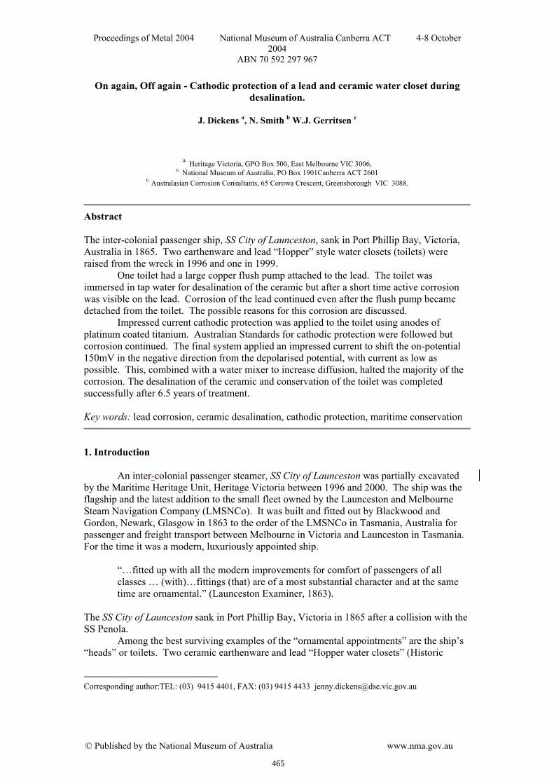
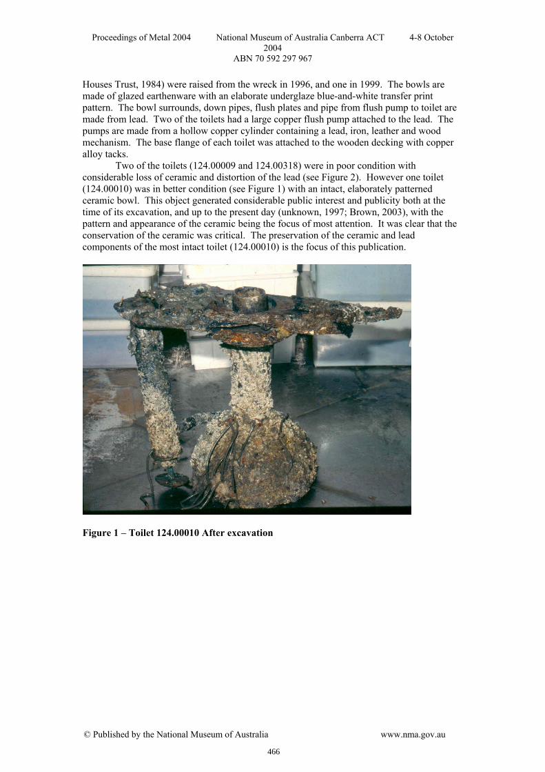
Two of the toilets (124.00009 and 124.00318) were in poor condition with considerable loss of ceramic and distortion of the lead (see Figure 2). However one toilet (124.00010) was in better condition (see Figure 1) with an intact, elaborately patterned ceramic bowl. This object generated considerable public interest and publicity both at the time of its excavation, and up to the present day (unknown, 1997; Brown, 2003), with the pattern and appearance of the ceramic being the focus of most attention. It was clear that the conservation of the ceramic was critical. The preservation of the ceramic and lead components of the most intact toilet (124.00010) is the focus of this publication.
Figure 1 – Toilet 124.00010 After excavation
466
Proceedings of Metal 2004 National Museum of Australia Canberra ACT 4-8 October 2004
ABN 70 592 297 967
© Published by the National Museum of Australia www.nma.gov.au
Figure 2 - Toilet 124.00318 After excavation 2. Initial treatment and decisions
When lifted from the sea all three toilets were covered with heavy marine concretions, sea life and silt. In aerated seawater lead is protected by the formation of insoluble lead sulphate, PbSO4, (North and MacLeod, 1987). On site and during transportation to Heritage Victoria’s conservation lab in Melbourne, the toilets were kept wet with seawater. Once back at the laboratory the bulk of the heavy marine concretions, sea life and silt were removed manually using a variety of plastic and metal tools and washing. The toilets were initially placed in a polypropylene tank containing a mixture of 1:1 seawater: tap water. After one week this was replaced with 100% tap water to start the standard ceramic desalination process (Pearson, 1987) while treatment decisions were formulated. Tap water was chosen because purified water is known to corrode lead (North 1987). The pump became detached from toilet 124.00010 in 1997 during x-raying and subsequent handling, and was stored and treated separately.
Initially it was intended to disassemble the toilets to separate the ceramic and lead since both required very different stabilisation treatments. Lead recovered from seawater is relatively stable, but because the seawater can penetrate porous ceramics, these require desalination to remove soluble salts (North, 1987; Pearson, 1987). Heritage Victoria’ s laboratory policy is to desalinate ceramics recovered from marine sites until three consecutive monthly chloride readings are at 10ppm or lower.
It was possible to remove the ceramic fragments from toilets 124.00009 and 124.00318 however it was not possible to do this for the intact toilet 124.00010. The lead flush plate was bolted through the ceramic to the lead with copper alloy nuts and bolts, two per plate. Attempting to undo these bolts, while theoretically possible was considered to pose an unacceptable risk to the ceramic and soft lead. Unlike the toilets from the CSS Alabama (Mardikian, 1997), the lead was in good condition and firmly attached to the whole of the ceramic, possibly applied with heat. These toilets did not have cast iron bases whereas those from the CSS Alabama did.
467
Proceedings of Metal 2004 National Museum of Australia Canberra ACT 4-8 October 2004
ABN 70 592 297 967
© Published by the National Museum of Australia www.nma.gov.au
The decision to desalinate the ceramic leaving it attached to the lead complicated the treatment considerably. At the same time (about 12 months after excavation) significant amounts of active lead corrosion became visible on the lead and in the tank containing the toilet. After discussion (MacLeod, 1997) an attempt was made to halt the corrosion by creating 500ppm solution of sulphate ion (SO4
2-) in tap water using sulphuric acid. However corrosion continued and we were concerned about the possibility of introducing sulphate salts to the ceramic, which could deliquesce and crystallise in the future (Halsberghe, 2002). Other inhibitors such as carbonate had similar potential salt problems to the sulphate. We considered that introducing more soluble salts would be counter-productive to the overall aim of desalinating the ceramic. Therefore the toilet was placed in tap water without inhibitors.
The use of a sacrificial magnesium anode was also considered however magnesium anodes are known to be rapidly consumed in cathodic protection situations (Standards Australia, 1992) and this could have introduced unacceptable levels of magnesium ions or magnesium salts to the ceramic. Instead, after advice from a corrosion engineer (Robilliard, 1996), the staff at Heritage Victoria collaborated with a corrosion engineering company, Remedial Engineering, to develop an impressed current cathodic protection system. 3.1 Corrosion
The reasons for the occurrence of the active corrosion on toilet 124.00010 are complex and have not been fully resolved. As the toilet without a pump (124.00009) that was excavated did not show this corrosion, it was assumed that the presence of the copper pump on toilet 124.00010 had led to the establishment of a galvanic cell i.e. anodic sites on the surface of the lead. There is a large difference (0.468V) between the standard Electromotive Force Potentials (emf) for copper (+0.342V) and lead (-0.126V) (Jones, 1996) indicating that copper is cathodic to lead, and therefore one would expect the corrosion of the lead to be accelerated when attached to copper. Even when the pump was removed the lead continued to corrode. However, when the third toilet (124.00318) was excavated in 1999 and placed into tap water, no visible corrosion occurred despite the presence of the copper flush pump. The copper alloy bolts remained on all three toilets during treatment. Given that they were present on all three toilets it appears that their presence did not contribute greatly to the corrosion of toilet 124.00010.
Other possible reasons for the differences between the corrosion rates of the three toilets could be: 3.1.1. Degree of de-concretion
Initially toilet 124.00010, being the most photogenic, was more thoroughly de-concreted than the other two toilets. All the organic marine life was removed from the toilets to limit damage from organic acids (North 1987), while small amounts of carbonate concretions (coral and shell) remained. However, toilet 124.00318 was de-concreted to a similar extent three years after excavation and is not showing any visible corrosion nearly one year later. Therefore, it is unlikely that the degree of de-concretion affected the corrosion. It is possible that the presence of carbonate concretions could have promoted inhibition of the lead corrosion, as it is known that chalk can actively promote passivation of lead roofs (Bordass, 1998). 3.1.2. Composition differences between the toilets
Preliminary analysis of the metal composition was done by Inductively Coupled Plasma – Mass Spectroscopy (ICP-MS). Initial readings indicated both toilets (124.00009 and 124.00010) were about 99.8% lead with minor additions of copper, tin and other metals. Ideally further analysis would be done running repeat samples and including the third toilet (124.00318) in the testing.
468
Proceedings of Metal 2004 National Museum of Australia Canberra ACT 4-8 October 2004
ABN 70 592 297 967
© Published by the National Museum of Australia www.nma.gov.au
3.1.3. Compositional differences within the lead of toilet 124.00010
There are several bands of light and dark coloured metal visible on the body (see Figure 4). It is possible that lead of different compositions may have been used to make the lead component. This may represent different pours during the casting process, perhaps due to crucible size or other factors. Toilet 124.0009 only shows one different coloured band and none are visible on toilet 124.00318. We hope to be able to analyse the various metal compositions in the future. 3.1.4. Effects of chlorides
The chlorides diffusing out of the ceramic increases the chloride content in the desalination water. The increase in chloride level may have an influence on the corrosion rate by increasing the conductivity of the water and breaking down the protective films initially produced by other seawater constituents (Burns, 1948). The other two toilets had far less ceramic remaining and this would have led to less chloride being present in the tap water in the tank. 4. Potential measurements
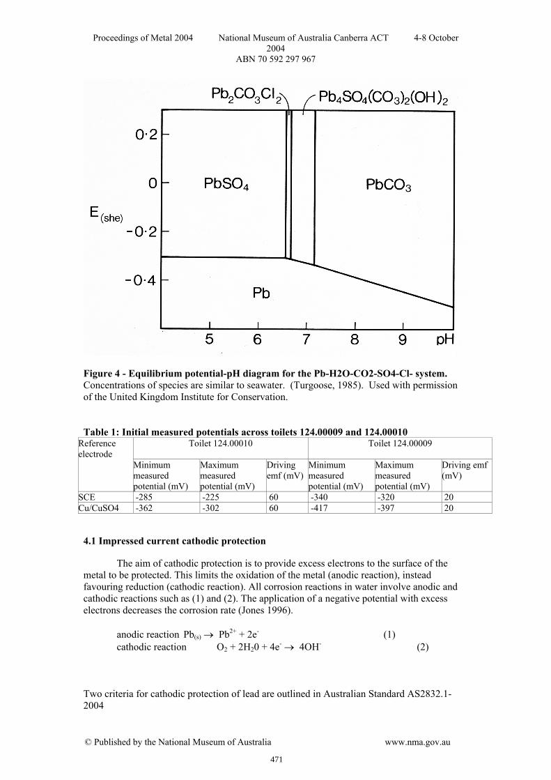
To try to understand the electrochemical state of the toilet, a single set of corrosion potential (Ecorr) measurements were taken using a Saturated Calomel Electrode (SCE) as the reference electrode. Using a Digital Multimeter set on D.C voltage, the negative (COM) terminal was connected to the toilet with an alligator clip above the water line, and the SCE was connected to the positive (V) terminal. This set up makes the toilet negative to the SCE. [When using digital multimeters it is also possible to take the readings by connecting the negative terminal to the electrode and the positive terminal to the structure because digital meters will display negative readings. However when using an analogue multimeter our set up is essential as analogue multimeters do not have a negative scale, and therefore users would not get a reading if the more conventional connection format was followed.] The SCE was then positioned over various parts of the toilet and the potentials recorded at each location. These readings were taken for both toilets 124.00009 and 124.00010 and the results are summarised in Table 1 below. The SCE is +241mV with respect to (wrt) the Standard Hydrogen Electrode (SHE). Standard electromotive and Pourbaix data are given wrt the SHE in theoretical literature (Pourbaix, 1974) but the SCE is often used in real applications because of its sturdy nature. Values in cathodic protection literature are generally quoted wrt the Saturated Copper/Copper Sulphate (Cu/CuSO4) electrode, which is 74mV wrt SCE (Jones, 1996). Where possible all values in this paper have been converted to SCE.
The toilets were immersed in Melbourne tap water for the desalination process. Analysis of Melbourne water based on the average of July 1999 to June 2004 data (Melbourne Water, 2004) gives the following parameters:
Total dissolved solids (TDS) mg/L 35 to 90 pH range: 6.9 to 7.8 Hardness range mg/L 12.0 to 25.0 Total alkalinity (as CaCO3) mg/L 11.3 to 14.0 Specific Conductance µS/cm 55 to 138 Sulphates mg/L 0.8 to 8.3
In applying these parameters using the median value of the range and assuming a temperature of 25oC in the room, a calculated Langelier Saturation Index (LSI) returns a value of -2.60.
469
Proceedings of Metal 2004 National Museum of Australia Canberra ACT 4-8 October 2004
ABN 70 592 297 967
© Published by the National Museum of Australia www.nma.gov.au
The LSI is the difference between the pH of a water sample, and the pH at which that water sample would be saturated in calcium carbonate (RMCC, 1999). A negative LSI means that the water dissolves calcium carbonate, and therefore passivation due to PbCO3 film formation may be reduced. While the levels of sulphate in Melbourne water are very low, PbSO4 could have been be formed on the lead by residual sulphates from the earlier inhibition attempt. However since corrosion continued it seemed likely that this layer was now either absent or damaged.
The resistivity of the water gives an indication to the rate of corrosion that may occur. The resistivity of Melbourne tap water calculated from the Specific Conductance parameter (Melbourne Water, 2004) ranges from 7,246 to 18,181 Ωcm. The corrosivity of the water based on the resistivity therefore ranges from moderate to slight (British Standards Institute, 1973).
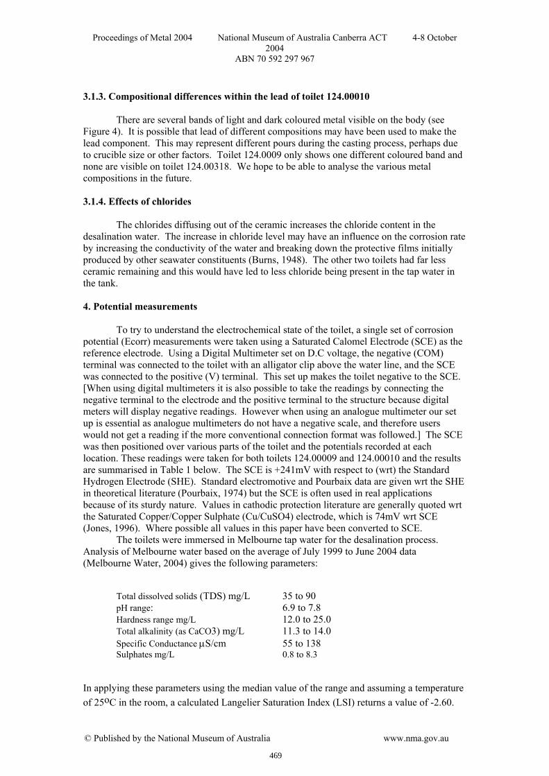
The initial corrosion potentials were measured over various parts of the toilets (see Table 1). The range of corrosion potentials was -320 to -340mV wrt SCE across the stable toilet 124.00009. For the corroding toilet, 124.00010, readings with the SCE ranged from -285mV to -225mV over the exterior surface of the metal. Two equilibrium potential-pH diagrams were consulted (Turgoose, 1985), see Figures 3 and 4. However, since the composition of the desalination solution was not the same as either of these diagrams they could only be used as an indication of the corrosive behaviour of the two toilets. Since the potential range across the non-corroding toilet is much less (20mV) compared to the corroding toilet (60mV), it is possible that the higher emf is causing the corrosion and shifting the potential of the toilet into a corrosive zone. It is unclear what created this higher emf. Figure 3 – Pourbaix diagram for the Pb-H2O system. (Turgoose, 1985). Used with permission of the United Kingdom Institute for Conservation.
Figure 3 – Pourbaix diagram for the Pb-H2O system. (Turgoose, 1985). Used with permission of the United Kingdom Institute for Conservation.
470
Proceedings of Metal 2004 National Museum of Australia Canberra ACT 4-8 October 2004
ABN 70 592 297 967
© Published by the National Museum of Australia www.nma.gov.au
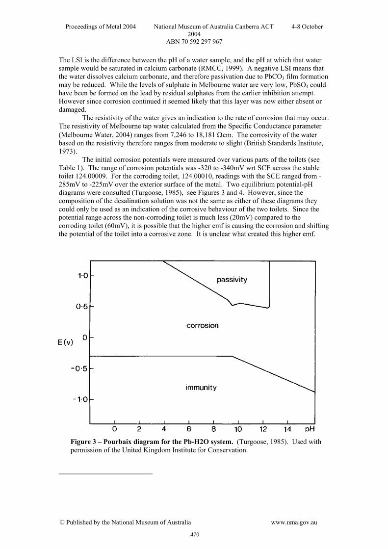
Figure 4 - Equilibrium potential-pH diagram for the Pb-H2O-CO2-SO4-Cl- system. Concentrations of species are similar to seawater. (Turgoose, 1985). Used with permission of the United Kingdom Institute for Conservation. Table 1: Initial measured potentials across toilets 124.00009 and 124.00010
Reference electrode
Toilet 124.00010 Toilet 124.00009
Minimum measured potential (mV)
Maximum measured potential (mV)
Driving emf (mV)
Minimum measured potential (mV)
Maximum measured potential (mV)
Driving emf (mV)
SCE -285 -225 60 -340 -320 20 Cu/CuSO4 -362 -302 60 -417 -397 20
4.1 Impressed current cathodic protection
The aim of cathodic protection is to provide excess electrons to the surface of the metal to be protected. This limits the oxidation of the metal (anodic reaction), instead favouring reduction (cathodic reaction). All corrosion reactions in water involve anodic and cathodic reactions such as (1) and (2). The application of a negative potential with excess electrons decreases the corrosion rate (Jones 1996). anodic reaction Pb(s) → Pb2+ + 2e- (1) cathodic reaction O2 + 2H20 + 4e- → 4OH- (2) Two criteria for cathodic protection of lead are outlined in Australian Standard AS2832.1-2004
471
Proceedings of Metal 2004 National Museum of Australia Canberra ACT 4-8 October 2004
ABN 70 592 297 967
© Published by the National Museum of Australia www.nma.gov.au
Clause 2.2.2.4. “The criteria for the protection of a buried lead structure is to maintain a potential on all parts of the structure equal to, or more negative than, -650 mV with respect to a copper/copper sulphate reference electrode when the structure is in aerated conditions…”
[-650 mV wrt Cu/CuSO4 = -574 mV wrt SCE – this figure will be used henceforth.]
Clause 2.2.3. “The criterion for the protection of a buried structure shall be to maintain an instantaneous off-potential on all parts of the structure, which is at least 100 mV more negative than the depolarized potential”
However, these recommendations are for buried rather than immersed lead structures. Morgan (1987) also recommends a 100 mV negative polarisation of the potential of lead immediately after switching off the current for a buried structure. Similarly a British Standard (CP 1021:1973) identifies the cathodic protection current for lead as -0.6V wrt Cu/CuSO4 without specifying if the lead is buried or immersed. The Australian Standard AS2832.3-1992 for immersed structures does not give criteria for lead specifically but states: “The accepted practice for the protection of mixed metallic structures is to maintain a negative potential at least equal to that required for the most anodic metal between all structure surfaces and a copper/copper sulphate reference electrode.”
Pourbaix (1974) notes that lead can be cathodically protected by lowering its potential with respect to SHE to below -0.3V in acid or neutral solutions or below -0.4V to -0.8V (depending on the pH) in alkaline solutions. Despite some ambiguity across the various standards, the cathodic protection was set up following the criteria in clause 2.2.2.4 of AS2832.1-2004.
472
Proceedings of Metal 2004 National Museum of Australia Canberra ACT 4-8 October 2004
ABN 70 592 297 967
© Published by the National Museum of Australia www.nma.gov.au
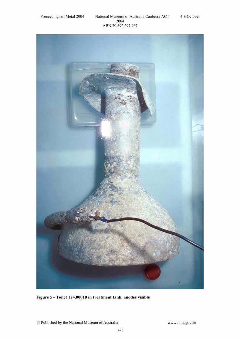
Figure 5 - Toilet 124.00010 in treatment tank, anodes visible
473
Proceedings of Metal 2004 National Museum of Australia Canberra ACT 4-8 October 2004
ABN 70 592 297 967
© Published by the National Museum of Australia www.nma.gov.au
4.2 Cathodic protection method I
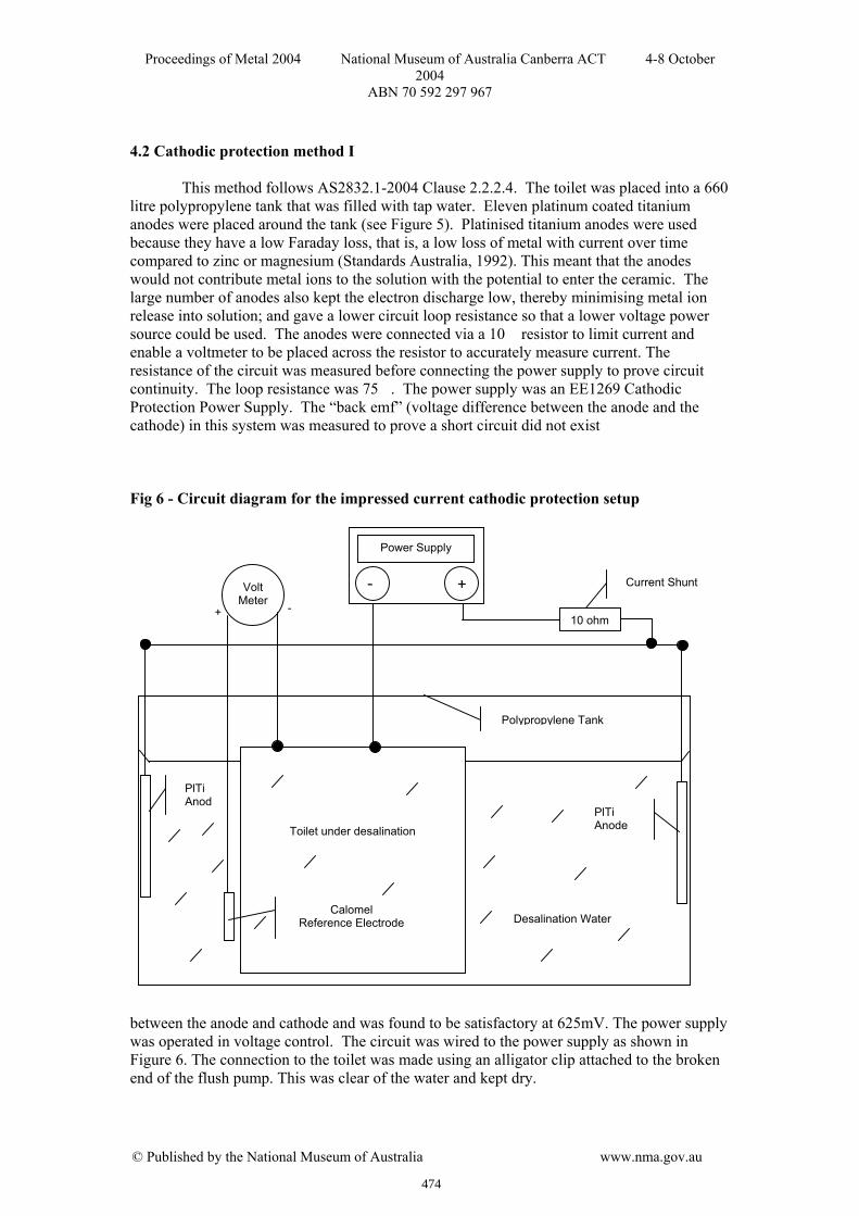
This method follows AS2832.1-2004 Clause 2.2.2.4. The toilet was placed into a 660 litre polypropylene tank that was filled with tap water. Eleven platinum coated titanium anodes were placed around the tank (see Figure 5). Platinised titanium anodes were used because they have a low Faraday loss, that is, a low loss of metal with current over time compared to zinc or magnesium (Standards Australia, 1992). This meant that the anodes would not contribute metal ions to the solution with the potential to enter the ceramic. The large number of anodes also kept the electron discharge low, thereby minimising metal ion release into solution; and gave a lower circuit loop resistance so that a lower voltage power source could be used. The anodes were connected via a 10 resistor to limit current and enable a voltmeter to be placed across the resistor to accurately measure current. The resistance of the circuit was measured before connecting the power supply to prove circuit continuity. The loop resistance was 75. The power supply was an EE1269 Cathodic Protection Power Supply. The “back emf” (voltage difference between the anode and the cathode) in this system was measured to prove a short circuit did not exist Fig 6 - Circuit diagram for the impressed current cathodic protection setup
between the anode and cathode and was found to be satisfactory at 625mV. The power supply was operated in voltage control. The circuit was wired to the power supply as shown in Figure 6. The connection to the toilet was made using an alligator clip attached to the broken end of the flush pump. This was clear of the water and kept dry.
Current Shunt
+ -
- +
10 ohm
Power Supply
PlTi Anod
PlTi Anode Toilet under desalination
Volt Meter
Calomel Reference Electrode Desalination Water
Polypropylene Tank
474
Proceedings of Metal 2004 National Museum of Australia Canberra ACT 4-8 October 2004
ABN 70 592 297 967
© Published by the National Museum of Australia www.nma.gov.au
The cathodic protection system was switched on and the output voltage increased in order to obtain an on-potential on the lead of -576mV wrt SCE, as specified in the Australian Standard. However, it was initially set at an on-potential of -530mV (rather than at -576mV) as it was considered the less negative level was more prudent as an initial attempt, and it could be gradually increased later if required. The applied protection current at this point was 21.5mA
Readings were taken daily (see Table 2) and show lead potentials remaining relatively steady but with the protection current gradually increasing. Following Ohms Law, this increase in current indicates that if the voltage was constant, the resistance of the system must have decreased. The decrease in the circuit resistance would occur with a decrease in the water resistivity (or increase in conductivity) probably caused by the increasing level of chlorides and other salts in the water. Table 2 : Initial potential readings for toilet 124.00010 Date Potential (mV) Protection Current (mA) 18/2/98 -530 21.5 19/2/98 -540 21.3 20/2/98 -541 21.7 23/2/98 -539 22.9 26/2/98 -530 26.6 27/2/98 -534 27.3 3/3/98 -530 31.8 For eight days the water appeared crystal clear with small bubbles (presumably oxygen) coming off the anodes. But after 14 days the anodes were found corroding and crumbling on the base of the tank. There was thick, furry, silver-coloured lead corrosion over the side of the toilet and around the base. The system was turned off and small samples of corrosion products were removed and analysed using X-ray diffraction (XRD). The XRD results seem to indicate the active corrosion products on toilet 124.00010 were Pb3(CO3)2(OH)2 and PbCl2. Other stable corrosion products found were common lead corrosion products, as found in aerobic, marine sites (PbClOH and PbSO4) and land sites (PbCO3 and PbO2) (North and MacLeod, 1987).
The pH and chloride ion concentration of the solution was measured (see Table 3). pH was measured using a TPS-Ionode pH meter and chloride readings were taken using a TPS-Ionode electronic chloride meter with a Ag/AgCl2 electrode. It is possible the electrolytic decomposition of the water caused pH changes at the anode and cathode, but the measured pH of samples taken from near the lead and near the anodes at the side of the tank did not show a large variation. Table 3: pH and [Cl-] of water samples taken from the tank holding toilet 124.00010 following cathodic protection
Sample pH [Cl-]/ppm Near lead 5.2 - 5.3 46 - 47 Edge of tank 5.5 15 - 20 Tap water 6.5 - 7 22 Although the anodes had crumbled there was no evidence of titanium or platinum
corrosion products from the XRD analysis. This may be because the corrosion products were soluble in water. The anodes were specified for 0.3mA/cm. Through a 10 resistor the maximum current reached was 31.8mA. Over 11 anodes this is 2.89mA per anode. As each anode is 200mm, equating to 0.14mA/cm, it appears that the anodes were not overloaded. However it is possible that the increasing current (caused by the salts in the solution
475
Proceedings of Metal 2004 National Museum of Australia Canberra ACT 4-8 October 2004
ABN 70 592 297 967
© Published by the National Museum of Australia www.nma.gov.au
decreasing the solution resistivity) may have over polarised the lead and anodes, leading to corrosion.
The SCE was recalibrated, the power supply disconnected and the potential of the toilet was measured several times over three weeks (see Table 4) using a SCE at various points around the toilet which gave, as before, slight differences over the whole toilet. During the two weeks that the impressed current cathodic protection system was operating, the lead potential range had decreased from the initial range of 60mV to 40mV. Two weeks after the impressed current had been de-energised (disconnected) the difference in potential range had further decreased to 30mV. After another week the potential range remained at around 30mV. Since the un-corroding toilet had a potential difference of 20mV it was assumed the driving potential between the anodic and cathodic sites on this toilet was now negligible, due to passivation by the cathodic protection. However, it was decided to recommence the cathodic protection because the depolarised potential was returning towards potentials at which the toilet had previously been corroding. It was also thought that the impressed current might set up an ionic gradient across the solution encouraging dissolution of chloride ions into solution. Table 4: Toilet 124.00010. Potential measured wrt SCE, current off
Date
Timing and type of recording Maximum potential (mV)
Minimum potential (mV)
Driving emf (mV)
12/2/98 Potential before current applied - corrosion current
-285 -225 60
3/3/98 Immediately after current switched off - off potential
-410 -370 40
17/3/98 After 2 weeks - depolarised potential
-380 -350 30
24/3/98 After 3 weeks – depolarised potential
-374 -343 30
4.3 Cathodic protection method II.
This method follows AS2832.1-2004 Clause 2.2.3. A new system was set up using new electrodes and setting the power supply to current control. 12 anodes were connected in series with a 10 resistor to the positive terminal. The toilet was connected to the negative terminal with a dry alligator clip as before. The least negative depolarised potential reading of the lead was -343mV wrt SCE (Table 4). For this attempt, current was applied more conservatively to shift the depolarised potential 100mV in the negative direction i.e. to -440mV wrt SCE as per the Australian Standard clause 2.2.3. The results are listed in Table 5.
The system was set up with an applied current of 6.7mA from 2.2 V (see Table 5). A lead on-potential of -500mV gave an immediate off-potential of -415mV. Initially the potential range of on-potentials over the toilet was from -620 to -480mV. Over one month this range gradually increased to -660 to -480mV. The measured outputs were 7.6mA at 2.4V. The current was then increased to 15.6mA to counteract the expected water resistance decrease due to chlorides being extracted from the ceramic, as had happened during the first attempt.
After the next four days the water was crystal clear, whereas previously, small amounts of corrosion or scum had been visible on the water. However after 12 days the anodes had the appearance of beginning to crumble and small specks of metal were visible on the bottom of the tank. On and off-potential measurements were taken and the power was turned off. Off-potential measurements of – 450 to – 400 indicate the standard was being met (as specified in AS2832.1-2004 clause 2.2.3 which requires the off potential readings to be
476
Proceedings of Metal 2004 National Museum of Australia Canberra ACT 4-8 October 2004
ABN 70 592 297 967
© Published by the National Museum of Australia www.nma.gov.au
measured), but the range of potentials across the toilet had increased. Chloride levels and pH readings were taken indicating a high pH near the surface of the lead and a low pH near the anodes as expected from the electrolytic decomposition of water.
The toilet was left sitting in the tap water with the impressed current disconnected but after eight days active corrosion began to form over the lead surface. Since the chloride ion concentration was high (51ppm) the solution was replaced with fresh tap water. The anodes were cleaned in HNO3 and placed back in the tub. The circuit was reconnected using intermediate values of 10mA and 2.9 V. After 14 days a small amount of active corrosion was visible on areas of the lead toilet. There was also a build up of red precipitate on the anodes. It is possible that HPbO- (plumbous ion) had formed in the crevices of the lead where the alkalinity would be highest (Cherry 1994). As a negative ion, this would be attracted to the anodes. Previous XRD results had indicated lead was plating out on the anodes as brown PbSO4 and PbO2.
The current was decreased to 9.1mA and 2.8 V where the lead appeared to remain stable. An aquarium pump was also added to the system. This was to reduce the build up of high pH near the lead and acidity at the anodes.
After this period potential measurements were not taken regularly but the impressed current and stirrer remained on. The decrease in protection current caused an increase in on-potential and an increase in variation over the toilet. The final on-potential readings ranged from -690 to -500mv wrt SCE – which is comparable to AS2832.1-2004 Clause 2.2.2.4. Because the system was not turned off, there are no further instantaneous off-potentials to compare to Clause 2.2.3. However, previous readings were from -450 to -400, so around 100mV more negative than the depolarised potential of -343mV. It appeared there was not the problem of over-polarisation as had happened in the first attempt, where high chloride concentration had caused breakdown of protective films.
Chloride measurements taken after several months recorded 20ppm near the ceramic and 30ppm near the anodes. This appeared to show that the impressed current might attract negative chloride ions towards the anode, encouraging further release of chloride ions from the ceramic into solution.
Over nine months the tap water was changed twice and the anodes cleaned. Again a high pH was recorded at the metal surface (pH=10) so the aquarium pump was replaced with a more powerful stirrer. This circulated the water slowly but thoroughly. This new stirrer also reduced the amount of scum that was forming on the surface of the water. However minor corrosion was still noted so after 10 months a high-powered pump and stirrer rated for continual use replaced the earlier version.
Over 6.5 years the solution was changed approximately three times/year and the [Cl-] was monitored using an electronic chloride meter with an Ag/AgCl2 electrode until it dropped to 16ppm. The tap water was then replaced with reverse osmosis purified water. No corrosion occurred at this time indicating that the cathodic protection continued to be
477

Proceedings of Metal 2004 National Museum of Australia Canberra ACT 4-8 October 2004
ABN 70 592 297 967
© Published by the National Museum of Australia www.nma.gov.au
effective and the polarisation of the lead was maintained. It was possible the lead in solution may have interfered with the chloride meter readings. Therefore, the final [Cl-] measurements were done using ion chromatography (CSIRO, Melbourne). The final desalination took another four months until chloride levels, detected by ion chromatography, gave three consecutive monthly readings of less than 10ppm.
The toilet was then disconnected from the cathodic protection, removed from the tank and air dried. No new corrosion products formed and the lead had a whitish silver appearance (see Figure 7) Table 5: Measurements taken for toilet 124.00010 during current adjustment to reach stable cathodic protection.
Date 1998
Description mA V On-potential* range wrt SCE
/mV
On-Potential* variation/
mV
Off- potential* wrt SCE /mV
Off- potential* variation/
mV
pH [Cl-]/ppm
9/4 Initial set up 6.7 2.2 -500 -415 6.9 2.5 -620 to -480 140
14/4 7.2 2.6 -644 to -484 160 20/4 7.0 2.4 -656 to -489 167 24/4 7.5 2.4 27/4 7.4 2.4 4/5 7.5 2.4 -654 to -488 166 7/5 7.6 2.4 -659 to -480 179
14/5 Increase current 15.6 3.0 -700 to -500 200 27 15/5 15.5 2.95 18/5 crystal clear water 15.5 2.85 19/5 15.5 2.8 21/5 15.7 2.8 26/5 anodes crumbling,
power off 15.8 2.8 -640 to -440 200 -450 to -400 50
Water sample near lead surface
10.4 34
Water sample near anodes
4.3 34
3/6 active corrosion, power on
10.1 2.9 -620 to -440 180 51
5/6 10.2 2.9 9/6 10.4 2.95
10/6 10.4 2.95 12/6 10.6 2.95 -670 to -485 185
115/6 10.6 2.95 17/6 Slight corrosion 10.7 2.95
Decreased current 9.1 2.8 26/6 9.2 2.8 -690 to -500 190 29/6 9.2 2.8
* The measurement shown as the “on potential..” is made up of two components being the metal’s polarised potential and the potential drop of the current flowing through the water (IR error). The measurement shown as the “off potential....“ indicates the metal’s polarised potential excluding the IR error and is the potential against which the level of protection is measured.
478
Proceedings of Metal 2004 National Museum of Australia Canberra ACT 4-8 October 2004
ABN 70 592 297 967
© Published by the National Museum of Australia www.nma.gov.au
Figure 7 – Toilet 124.00010 After Treatment
479
Proceedings of Metal 2004 National Museum of Australia Canberra ACT 4-8 October 2004
ABN 70 592 297 967
© Published by the National Museum of Australia www.nma.gov.au
5. Discussion
Toilet 124.00010 was desalinated using impressed current cathodic protection, initially following guidelines in AS2832.1-2004 Clause 2.2.2.4. An on potential level of -530mV wrt SCE reference electrode was achieved on the toilet with the system under voltage control. This depressed the original depolarised potential by 305mV i.e. similar to that recommended by Pourbaix (1974). However, after 12 days active corrosion was visible over the lead toilet and the anodes were crumbling. It is thought the continued desalination of the ceramic increased the chloride and other ion levels, and this increased the conductivity of the system. This caused an increase in current and possibly over-polarisation of the lead and anodes. pH changes from the electrolytic decomposition of water may have had an influence but pH measurements taken from near the anodes and cathode do not support this. A second attempt was made, following AS2832.1-2004 Clause 2.2.3. This recommended a potential almost 100mV more negative than the depolarised potential, in this case –343mV. Aiming for an instantaneous off-potential of -440mV, we found that an off potential level across the toilet of -400 to -450 mV wrt SCE achieved effective cathodic protection with the system under current control. Increasing the current produced the beginnings of corrosion so it was reduced. This corresponded to an on-potential of -500mV wrt SCE and a depolarised potential shift of -157mV. AS2832.1-2004 recommends -574mV wrt SCE or a depolarised potential shift of -100mV to cathodically protect buried lead. No standards are available for immersed lead but Pourbaix (1974) suggests that the potential of the lead be lowered to below about -0.3V. Our results show that for historic artefacts at least, published recommendations should be used as a guide and that trial and error methodology continues to be necessary.
Measurements throughout the second attempt (following AS2832.1-2004 Clause 2 .2.3) indicated a high pH near the lead and a low pH near the anodes as expected from the electrolytic decomposition of water. A water stirrer and pump was added to increase diffusion. When a powerful mixer with the capacity to agitate all the water in the tank was introduced, the remaining corrosion ceased and the cathodic protection became effective. The toilet remained in this configuration for four and a half years. The tap water was changed about three times/year. In the last year of treatment the tap water was replaced by purified (reverse osmosis) water and the cathodic protection continued to be effective.
We considered the possibility that aerated stirring of the water without the use of cathodic protection may have been sufficient to increase CO2 levels and protect the lead. The presence of dissolved carbon dioxide can form insoluble protective PbCO3, (Cerussite), which can passivate lead between pH 5 - 12 (Bordass, 1998). Similarly, it was not clear if leaving more of the carbonate concretions on the lead surface could have protected the lead by producing protective carbonates. However because of the negative LSI of the water the formation of PbCO3 may not have been favoured. Rather, the lack of a continuous layer may have favoured the development of corrosion cells. Therefore due to the lack of knowledge and information on these complex corrosion mechanisms it was felt that applying cathodic protection remained the most appropriate action.
During the treatment, regular readings of the concentration of chlorides were taken. Readings indicating higher [Cl-] near the anodes than near the toilet appeared to confirm that chlorides released by the ceramic were being attracted to the anodes and away from the ceramic. The toilet took an unexpectedly long time (6.5 years) to fully desalinate to the required level. Usually an earthenware object of this size would be expected to take 1 or 2.5 years to desalinate. However, the underside of the ceramic was covered in lead so all chloride ions had to pass through the glazed external face.
Once the chloride readings were at an acceptable level the toilet was removed from the tank and allowed to air dry. No new corrosion products formed during this process.
480
Proceedings of Metal 2004 National Museum of Australia Canberra ACT 4-8 October 2004
ABN 70 592 297 967
© Published by the National Museum of Australia www.nma.gov.au
When the object was dry, different light and dark grey bands across the lead became visible. The bowl was pale grey while the down pipe had two dark and one light coloured area. There was a small amount of pitting visible on the lead in the upper light coloured area of the lead area (around the bowl). Interestingly, the darker coloured areas of lead had not corroded indicating that different lead compositions on the toilet may have played a part in the lead corrosion. This supports the assumption that differing lead compositions within the toilet may have set up corrosion cells.
While there was a small amount of pitting visible on the lead in the upper light coloured bowl area, the ceramic was in excellent condition following this treatment and 1.5 years after completion does not show any evidence of deterioration caused by soluble salts. 6. Conclusions
A lead and ceramic toilet recovered from a maritime archaeological site was desalinated with the aid of impressed current cathodic protection to limit corrosion of the lead. Although some corrosion of the lead occurred during the initial set-up period, this was minimised with the impressed current cathodic protection system. A protection current was applied to shift the on-potential 150mV in the negative direction from the depolarised potential. The level of applied current is a determining factor and was applied as low as possible, however it could increase with increasing levels of dissolved salts in the tank. Australian Standards and Pourbaix (1974) provided some guidelines to determining the size of the potential shift needed; however the successful protection potential had to be found by trial and error. Thorough, continuous stirring to neutralise the electrolyte at the anode and cathode was an essential part of the treatment. The desalination treatment of the ceramic was completed successfully after 6.5 years of treatment and the ceramic is in excellent condition (Figure 7).
This was a complex and time consuming treatment not helped by the treatment being continued by six different contract staff, and lack of funding to conduct extensive analysis. Disassembly of the composite object could have avoided the need for cathodic protection but this was considered too high a risk for such a significant object. The lack of practical experience with cathodic protection on the part of the conservators (now rectified thanks to this treatment) may also have introduced some delays. While there was a small amount of pitting visible on the lead in the upper light coloured bowl area, the ceramic was in excellent condition and does not show any evidence of deterioration caused by soluble salts, even 1.5 years after the completion of the treatment. It was placed on display for nine months in 2004.
We hope that by discussing both the setbacks and successes of this treatment, we have illuminated some of the complexities of the conservation of such complex, composite, archaeological objects. Acknowledgements We would like to acknowledge Heritage Victoria's conservation staff who maintained the desalination and cathodic protection treatment over six years; Vanessa Roth, Andrew Viduka, Karina Acton and Barbara O’Brien. We would like to thank our work places: Heritage Victoria, Remedial Engineering and the National Museum of Australia who provided facilities and support to enable us to carry out this work. We are very grateful to Professor Brian Cherry from Monash University who has kindly commented on this paper. All remaining errors are the fault of the authors.
We would particularly like to acknowledge Dr Graham Robilliard of Robilliard Corrosion Services Pty Ltd, Melbourne who alerted us to the pH concentration build-ups, which can result from cathodic protection.
481
Proceedings of Metal 2004 National Museum of Australia Canberra ACT 4-8 October 2004
ABN 70 592 297 967
© Published by the National Museum of Australia www.nma.gov.au
References Bordass, B, (1998) The underside corrosion of lead roofs and its prevention, in English Heritage Research Transactions Metals Volume 1 English Heritage, London British Standards Institution, (1973), CP 1021:1973 Code of Practice for Cathodic Protection. Brown, A, (2003), Shipwreck Toilets – Jenny Dickens, Heritage Victoria, on Totally Wild, TV program, Channel 10, Australia Burns, R. M. (1948) Corrosion of Lead and Lead Alloy Cable Sheathing, in Corrosion Handbook (ed) Uhlig, H.H. John Wiley & Sons, Inc: New York Cherry, B. (1994), Personal communication, School of Physics and Materials Engineering, Monash University, Victoria Halsberghe, L, (2002), Ceramics threatened by acid-induced salts, in Conservation Science 2002, (eds) Townsend, J.H, Eremin, K and Adriaens, A, Institute of Conservation Science and the National Museums of Scotland, Archetype Publications Ltd: London Historic Houses Trust of New South Wales, (1984), Cleanliness is next to godliness: personal hygiene in New South Wales 1788-1901, The Historic Houses Trust of New South Wales, Sydney. Jones, D.A, (1996), The Technology and Evaluation of Corrosion, Ch 1 in Principles and Prevention of Corrosion 2nd ed. Prentice Hall MacLeod, I.D. (1997), Personal communication, Western Australian Museum, Western Australia. Mardikian, P, (1997), The Conservation of Two Composite Objects from the Confederate Raider Alabama (1864), in Underwater Archaeology, The Society for Historical Archaeology, Denise Lakey (ed), pp128-134 Morgan, J, (1987), Cathodic Protection, 2nd Edition, National Association of Corrosion Engineers, Houston, Texas. Melbourne Water, (2004), Analysis of Melbourne’s water for 2004, www.melbournewater.com.au North, N.A, (1987), Conservation of metals, in Conservation of Marine Archaeological Objects, C. Pearson (ed). Butterworths: London North, N.A. and MacLeod I.D. (1987), Corrosion of metals, in Conservation of Marine Archaeological Objects (ed) C. Pearson. Butterworths: London Pearson, C, (1987), Conservation of Ceramics, Glass, and Stone, in Conservation of Marine Archaeological Objects (ed) C. Pearson. Butterworths: London Pearson, C, (1987), On-site storage and conservation, in Conservation of Marine Archaeological Objects (ed) C. Pearson. Butterworths: London.
482
Proceedings of Metal 2004 National Museum of Australia Canberra ACT 4-8 October 2004
ABN 70 592 297 967
© Published by the National Museum of Australia www.nma.gov.au
Pourbaix, M, (1974), Atlas of Electrochemical Equilibria in Aqueous Solutions, 2nd English Edition National Association of Corrosion Engineers, Houston TX and Centre Belge d’Etude de la Corrosion CEBELCOR Bruxelles Robilliard, G, (1996), Personal Communication, Robilliard Corrosion Services Pty Ltd, Victoria. Royal Military College of Canada (RMCC), (1999), Langelier Saturation Index (LSI), in Corrosion Doctors, http://www.corrosion-doctors.org/CorrDocs/CDs.htm Standards Australia, Australian Standard Cathodic protection of metals . Part 1: Pipes and Cables. AS 2832.1-2004 (earlier versions 1985 and 1998) Standards Australia, Australian Standard Cathodic protection of metals . Part 3: Guide to Cathodic Protection of Metals – Fixed Immersed Structures. AS 2832.1-1992 Turgoose, S, (1985), The corrosion of Lead and Tin: Before and After Excavation, in Lead and Tin Studies in Conservation and Technology, (eds) G. Miles and S. Pollard, Occasional Papers, no. 3, United Kingdom Institute for Conservation, London. Unknown, (1863), Launceston Examiner, October 22 1863 Unknown, (1997), From the bowels of history, a classic Crapper, The Age, 16 April 1997, Melbourne
483