“om4 fiber – the next generation of multimode - bicsi multimode fibers.pdf“om4 fiber – the...
TRANSCRIPT
“OM4 Fiber – The Next Generation of Multimode"
Tony Irujo – Sales Engineertirujo@ofsoptics [email protected]
Outline
• Market Drivers
Outline
Market Drivers
• About Optical Fiber
• OM4 Fiber – What is it?
• OM4 Fiber Standards & Specifications& p
• OM4’s role for 40G & 100G Ethernet
Outline
• Market Drivers
Outline
Market Drivers
• About Optical Fiber
• OM4 Fiber – What is it?
• OM4 Fiber Standards & Specifications& p
• OM4’s role for 40G & 100G Ethernet
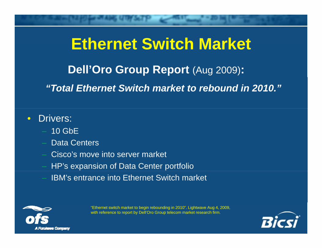
Ethernet Switch MarketEthernet Switch MarketDell’Oro Group Report (Aug 2009):
“Total Ethernet Switch market to rebound in 2010.”
• Drivers:– 10 GbE
D t C t– Data Centers– Cisco’s move into server market– HP’s expansion of Data Center portfolio– IBM’s entrance into Ethernet Switch market
“Ethernet switch market to begin rebounding in 2010”. Lightwave Aug 4, 2009, with reference to report by Dell’Oro Group telecom market research firm.
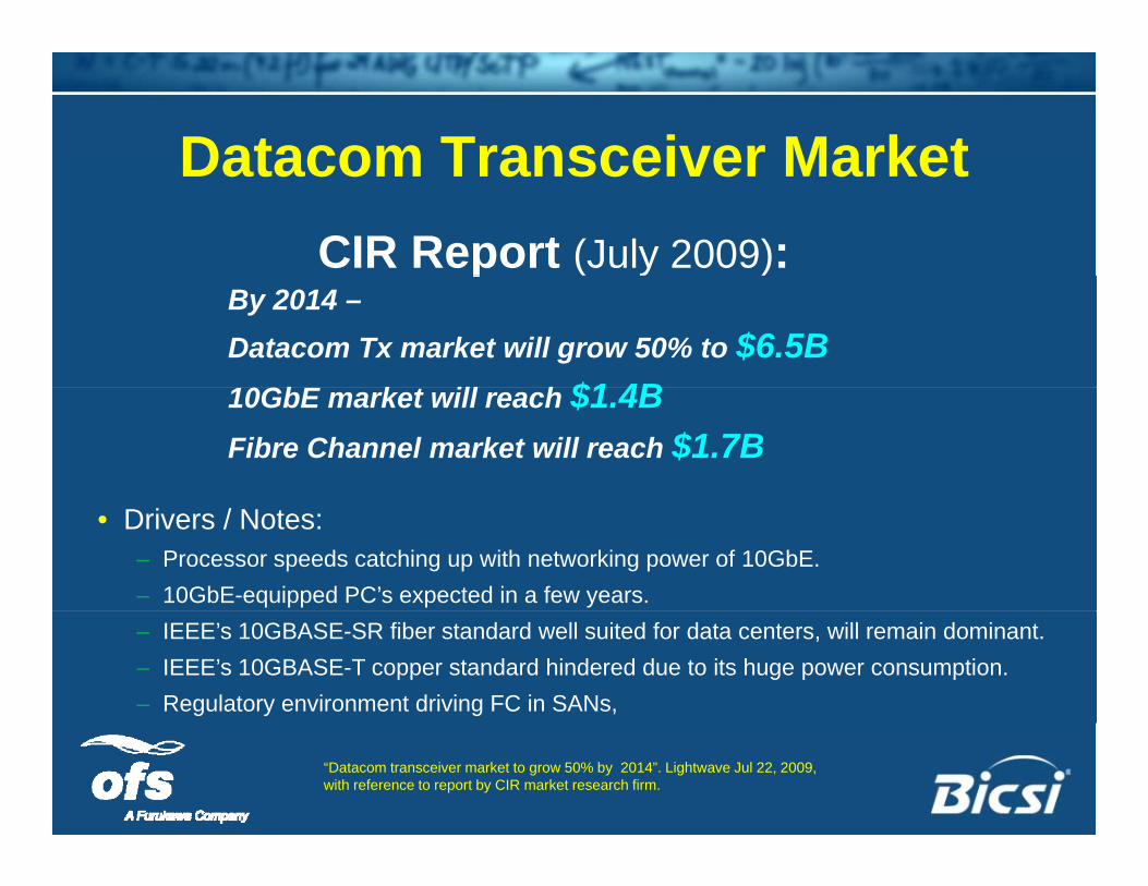
Datacom Transceiver MarketDatacom Transceiver MarketCIR Report (July 2009):p ( y )
By 2014 –Datacom Tx market will grow 50% to $6.5B10GbE k ill h $1 4B10GbE market will reach $1.4BFibre Channel market will reach $1.7B
• Drivers / Notes:– Processor speeds catching up with networking power of 10GbE.– 10GbE-equipped PC’s expected in a few years.– IEEE’s 10GBASE-SR fiber standard well suited for data centers, will remain dominant.– IEEE’s 10GBASE-T copper standard hindered due to its huge power consumption.– Regulatory environment driving FC in SANs,
“Datacom transceiver market to grow 50% by 2014”. Lightwave Jul 22, 2009, with reference to report by CIR market research firm.
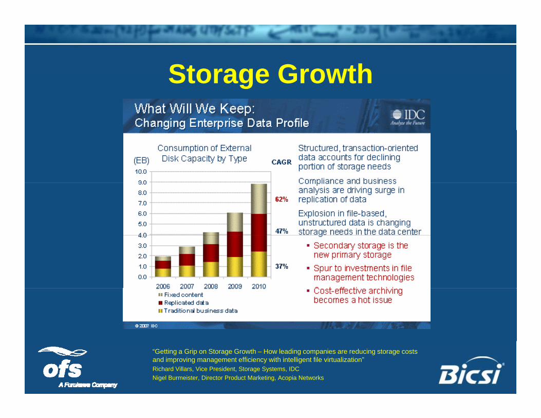
Storage GrowthStorage Growth
“Getting a Grip on Storage Growth – How leading companies are reducing storage costs and improving management efficiency with intelligent file virtualization”Richard Villars, Vice President, Storage Systems, IDCNigel Burmeister, Director Product Marketing, Acopia Networks
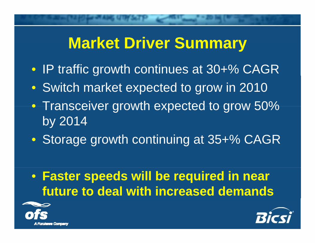
Market Driver SummaryMarket Driver Summary• IP traffic growth continues at 30+% CAGRg• Switch market expected to grow in 2010• Transceiver growth expected to grow 50%• Transceiver growth expected to grow 50%
by 2014St th ti i t 35+% CAGR• Storage growth continuing at 35+% CAGR
• Faster speeds will be required in near future to deal with increased demands
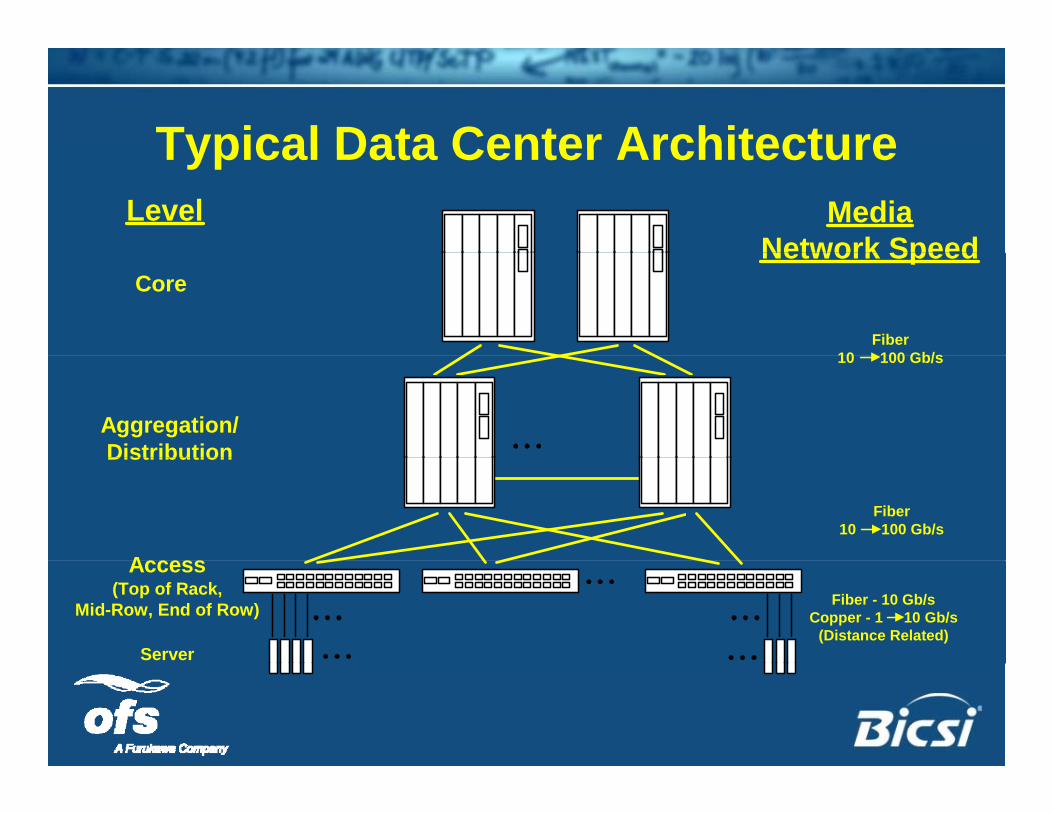
Typical Data Center ArchitectureTypical Data Center ArchitectureLevel Media
Network SpeedCore
Fiber10 100 Gb/s
Network Speed
Aggregation/Distribution
10 100 Gb/s
Access
Distribution
Fiber10 100 Gb/s
Server
Access(Top of Rack,
Mid-Row, End of Row) Fiber - 10 Gb/sCopper - 1 10 Gb/s
(Distance Related)
Outline
• Market Drivers
Outline
Market Drivers
• About Optical Fiber
• OM4 Fiber – What is it?
• OM4 Fiber Standards & Specifications& p
• OM4’s role for 40G & 100G Ethernet
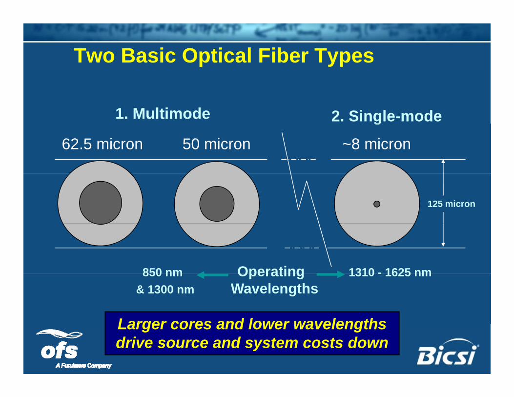
Two Basic Optical Fiber Types
1. Multimode 2. Single-modeg
62.5 micron 50 micron ~8 micron
125 micron
850 nm Operating 1310 - 1625 nm
Larger cores and lower wavelengths
850 nm Operating 1310 - 1625 nm & 1300 nm Wavelengths
Larger cores and lower wavelengths drive source and system costs down
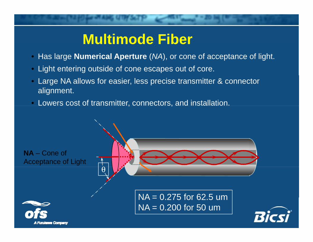
Multimode Fiber• Has large Numerical Aperture (NA), or cone of acceptance of light.• Light entering outside of cone escapes out of core.• Large NA allows for easier, less precise transmitter & connector
alignment.• Lowers cost of transmitter, connectors, and installation., ,
NA – Cone of Acceptance of Light
θθ
NA = 0 275 for 62 5 umNA = 0.275 for 62.5 um NA = 0.200 for 50 um
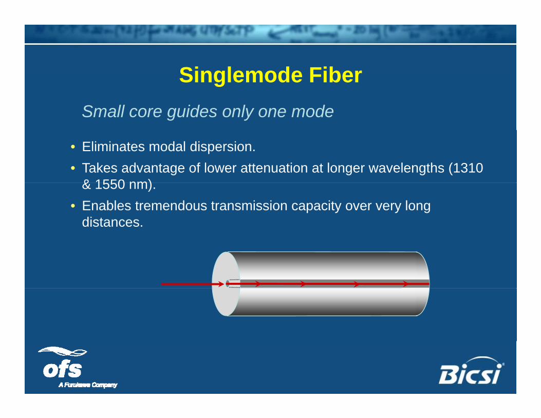
Singlemode FiberSinglemode FiberSmall core guides only one mode
• Eliminates modal dispersion.• Takes advantage of lower attenuation at longer wavelengths (1310
& 1550 nm)& 1550 nm).• Enables tremendous transmission capacity over very long
distances.
M lti d Si l d ?Multimode or Singlemode?
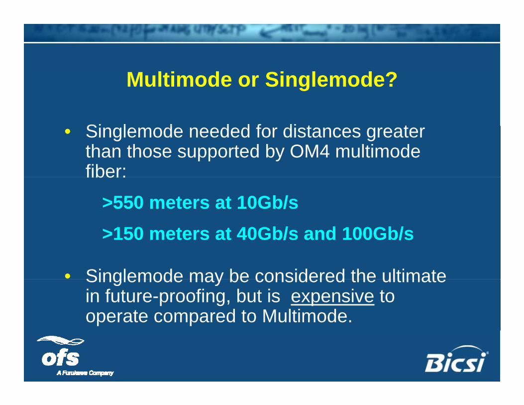
Si l d d d f di t t• Singlemode needed for distances greater than those supported by OM4 multimode fiber:fiber:
>550 meters at 10Gb/s150 t t 40Gb/ d 100Gb/>150 meters at 40Gb/s and 100Gb/s
• Singlemode may be considered the ultimateSinglemode may be considered the ultimate in future-proofing, but is expensive to operate compared to Multimode.
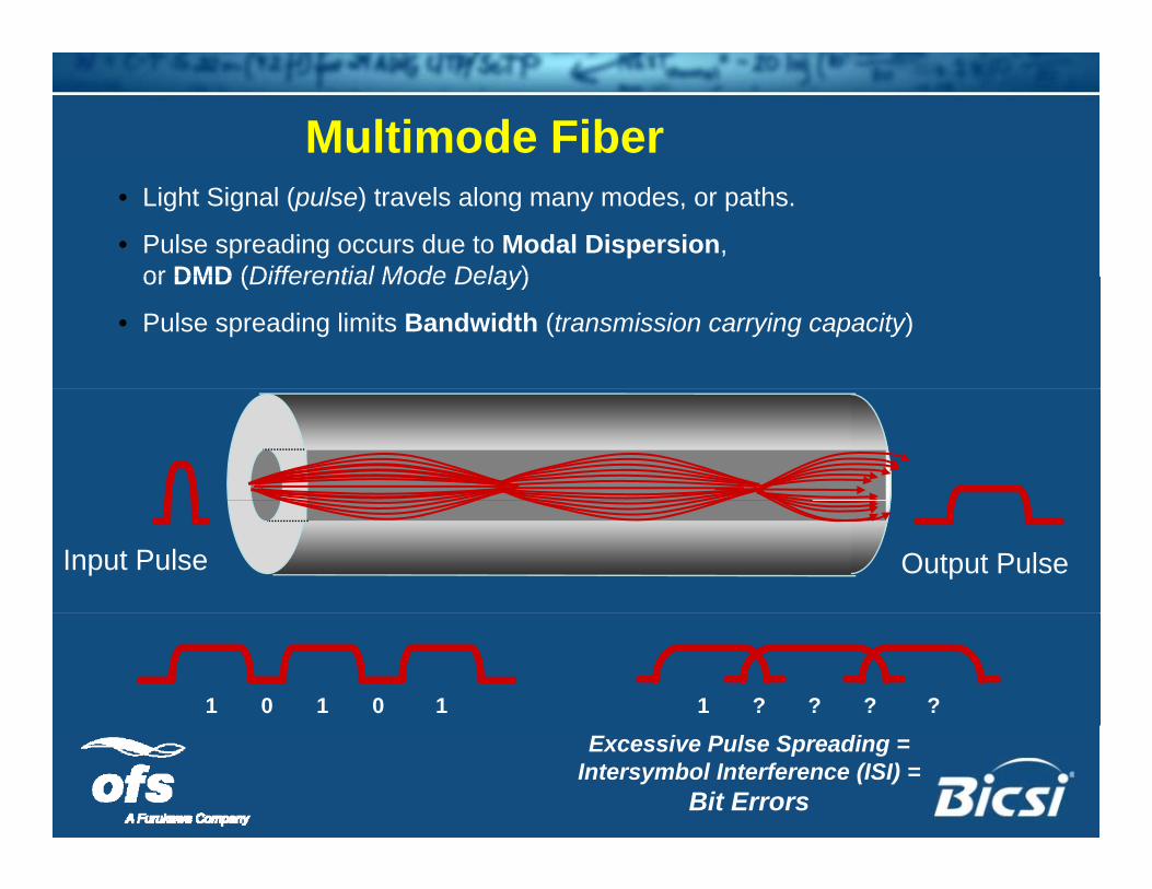
Multimode Fiber• Light Signal (pulse) travels along many modes, or paths.
• Pulse spreading occurs due to Modal Dispersion, or DMD (Differential Mode Delay)or DMD (Differential Mode Delay)
• Pulse spreading limits Bandwidth (transmission carrying capacity)
Input Pulse Output Pulse
1 0 1 10 ??? ?1
Excessive Pulse Spreading = Intersymbol Interference (ISI) =
Bit Errors
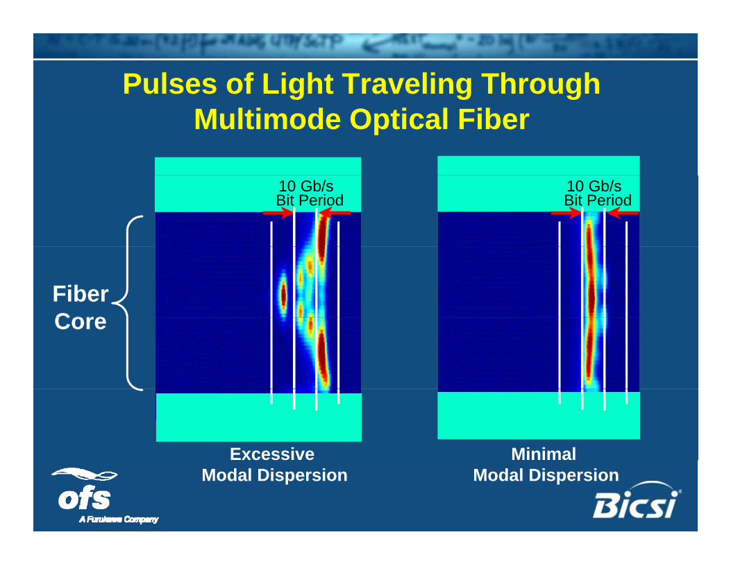
Pulses of Light Traveling Through Multimode Optical Fiber
10 Gb/sBit Period
10 Gb/sBit Period
FiberCoreCore
Excessive Minimal cess eModal Dispersion
aModal Dispersion
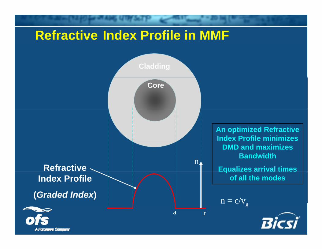
Refractive Index Profile in MMF
Cladding
Core
An optimized Refractive Index Profile minimizesIndex Profile minimizes
DMD and maximizes Bandwidth
Equalizes arrival times Refractive n
qof all the modesIndex Profile
(Graded Index) n = c/vgn c/vga r
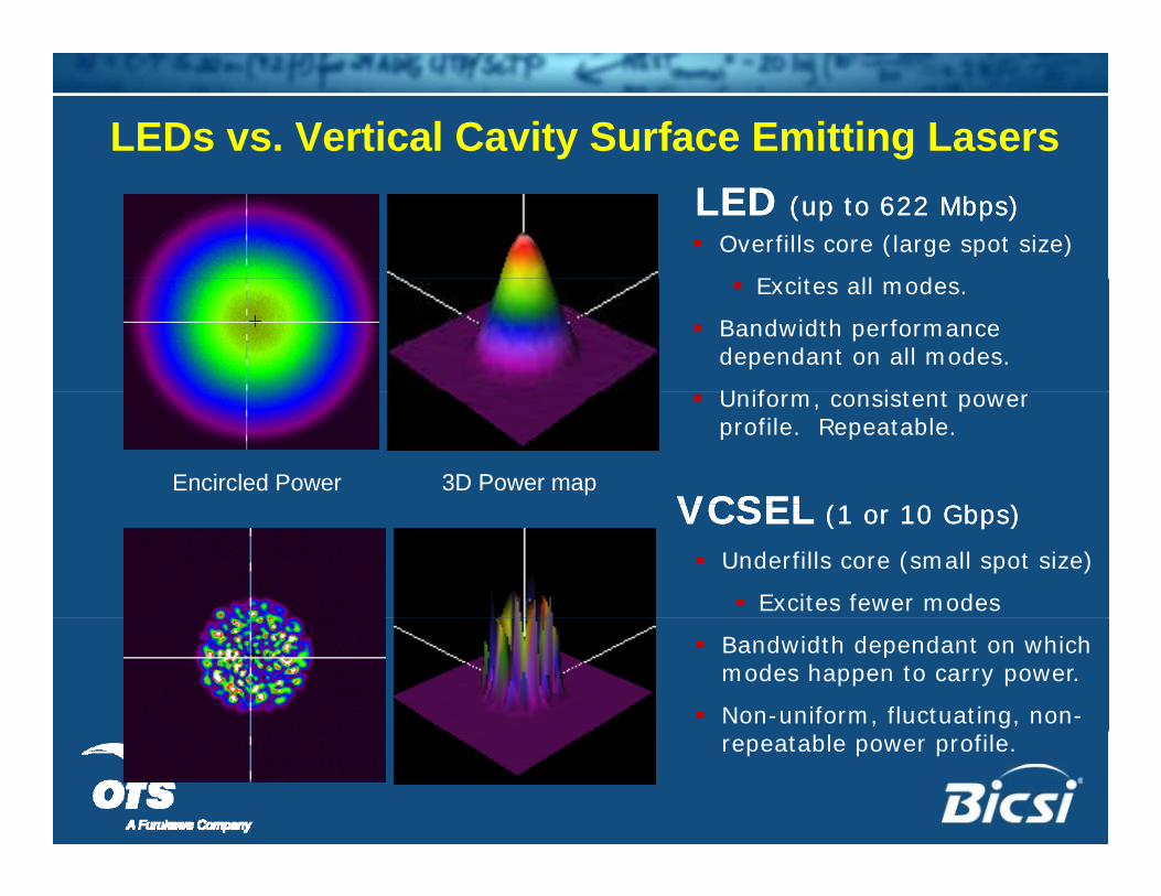
LEDs vs. Vertical Cavity Surface Emitting LasersLEDLED (up to 622 Mbps)(up to 622 Mbps) Overfills core (large spot size)
E it ll d Excites all modes.
Bandwidth performance dependant on all modes.
U if i t t
Encircled Power 3D Power map
Uniform, consistent power profile. Repeatable.
VCSELVCSEL (1 10 Gb )(1 10 Gb )
Underfills core (small spot size)
Excites fewer modes
VCSELVCSEL (1 or 10 Gbps)(1 or 10 Gbps)
Bandwidth dependant on which modes happen to carry power.
Non-uniform, fluctuating, non-repeatable power profile.
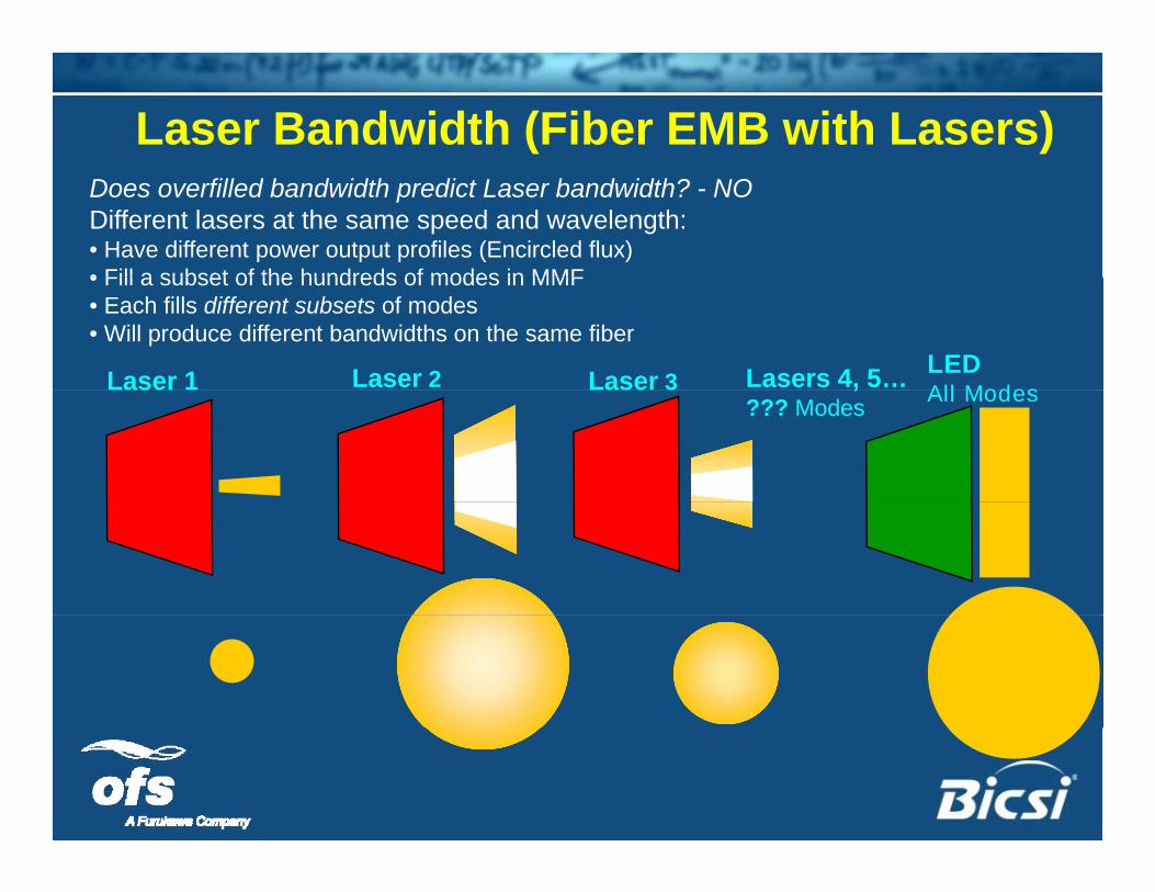
Laser Bandwidth (Fiber EMB with Lasers)Does overfilled bandwidth predict Laser bandwidth? - NODifferent lasers at the same speed and wavelength:• Have different power output profiles (Encircled flux)• Fill a subset of the hundreds of modes in MMF
Laser 1
• Fill a subset of the hundreds of modes in MMF• Each fills different subsets of modes• Will produce different bandwidths on the same fiber
Laser 2 Laser 3LEDAll Modes
Lasers 4, 5…ase ase 3 All Modes,
??? Modes
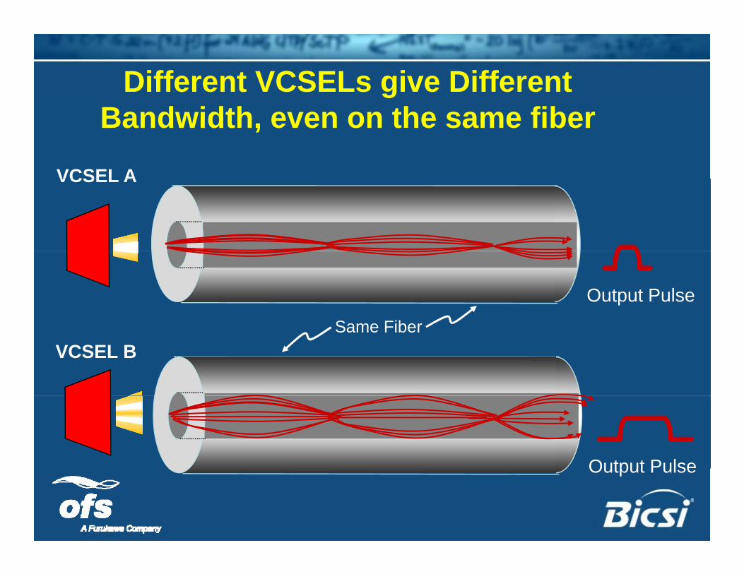
Different VCSELs give Different fBandwidth, even on the same fiber
VCSEL AVCSEL A
S Fib
Output PulseSame Fiber
VCSEL B
Output PulseOutput Pulse
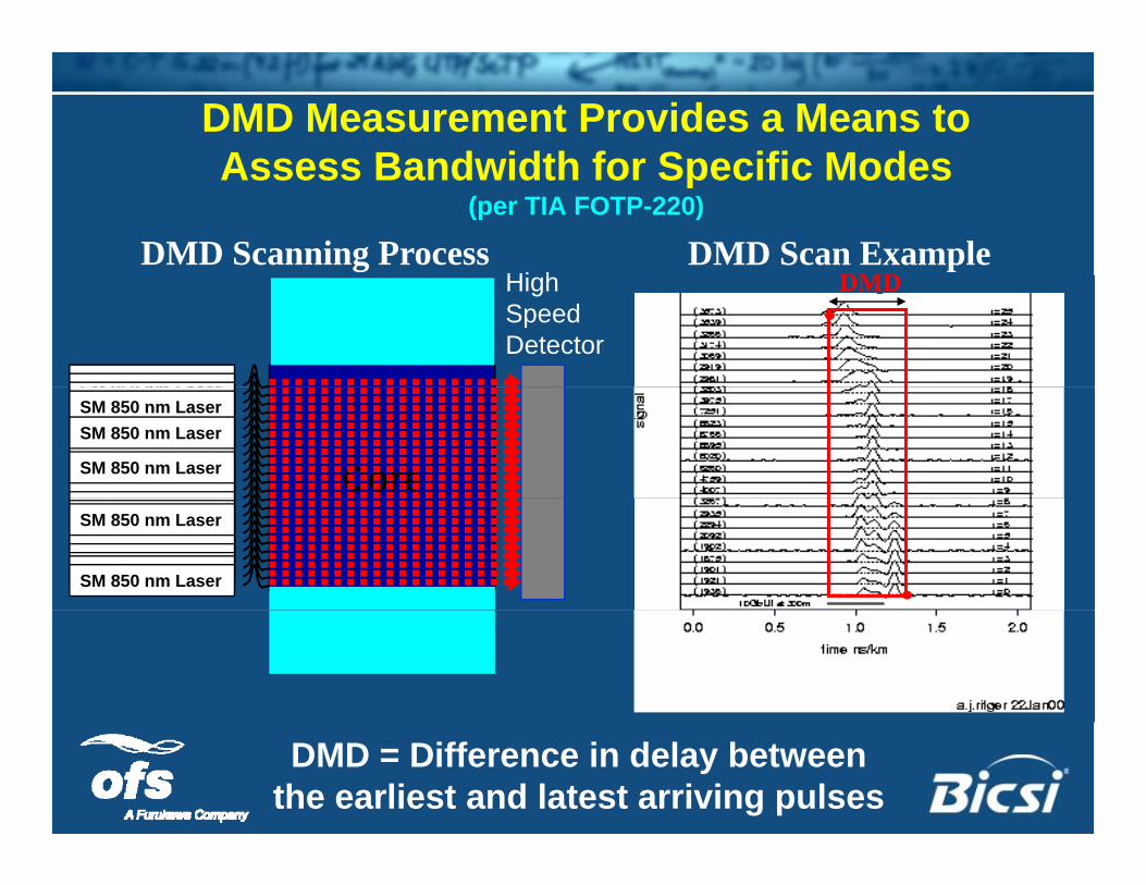
DMD Measurement Provides a Means to Assess Bandwidth for Specific ModesAssess Bandwidth for Specific Modes
(per TIA FOTP-220)
DMD Scanning Process DMD Scan ExampleDMDHi h DMDHigh
SpeedDetector
SM 850 nm LaserSM 850 nm Laser
Core
S 850 aseSM 850 nm LaserSM 850 nm LaserSM 850 nm LaserSM 850 nm LaserSM 850 nm Laser
SM 850 nm LaserSM 850 nm LaserSM 850 nm LaserSM 850 nm Laser
SM 850 LSM 850 nm LaserSM 850 nm LaserSM 850 nm LaserSM 850 nm Laser
SM 850 nm Laser
SM 850 nm LaserSM 850 nm LaserSM 850 nm Laser
SM 850 nm LaserSM 850 nm LaserSM 850 nm LaserSM 850 nm LaserSM 850 nm Laser
SM 850 nm LaserSM 850 nm Laser
DMD = Difference in delay betweenthe earliest and latest arriving pulses
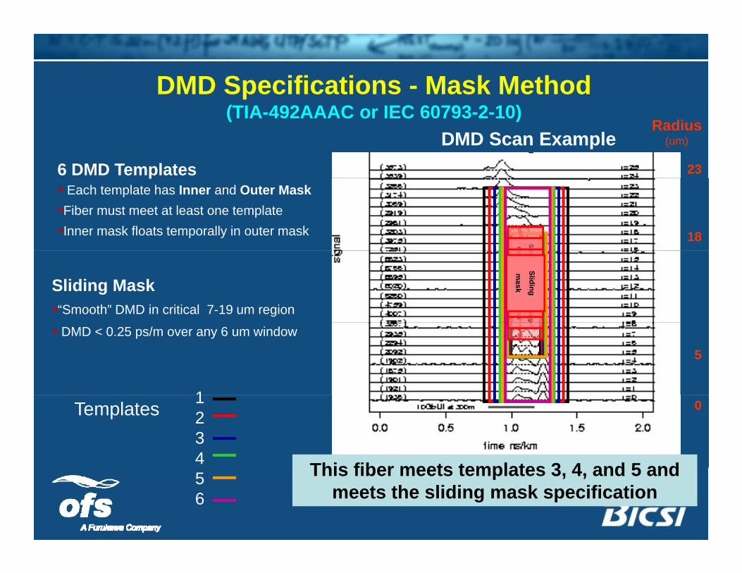
DMD Specifications - Mask Method(TIA 492AAAC IEC 60793 2 10)
DMD Scan Example6 DMD Templates
(TIA-492AAAC or IEC 60793-2-10)Radius
(um)
23p Each template has Inner and Outer MaskFiber must meet at least one templateInner mask floats temporally in outer mask 18Slm Slm iding
mask Sliding
mask Sliding
mask Sliding
mask Sliding
mask Sliding
mask
Sliding
mask
Sliding
mask
Sliding
mask
Sliding
mask
iding
mask Sliding
mask Sliding
mask
Sliding
maskSliding Mask
“Smooth” DMD in critical 7-19 um region
5
1
DMD < 0.25 ps/m over any 6 um window
01234
Templates
This fiber meets templates 3 4 and 5 and56
This fiber meets templates 3, 4, and 5 and meets the sliding mask specification
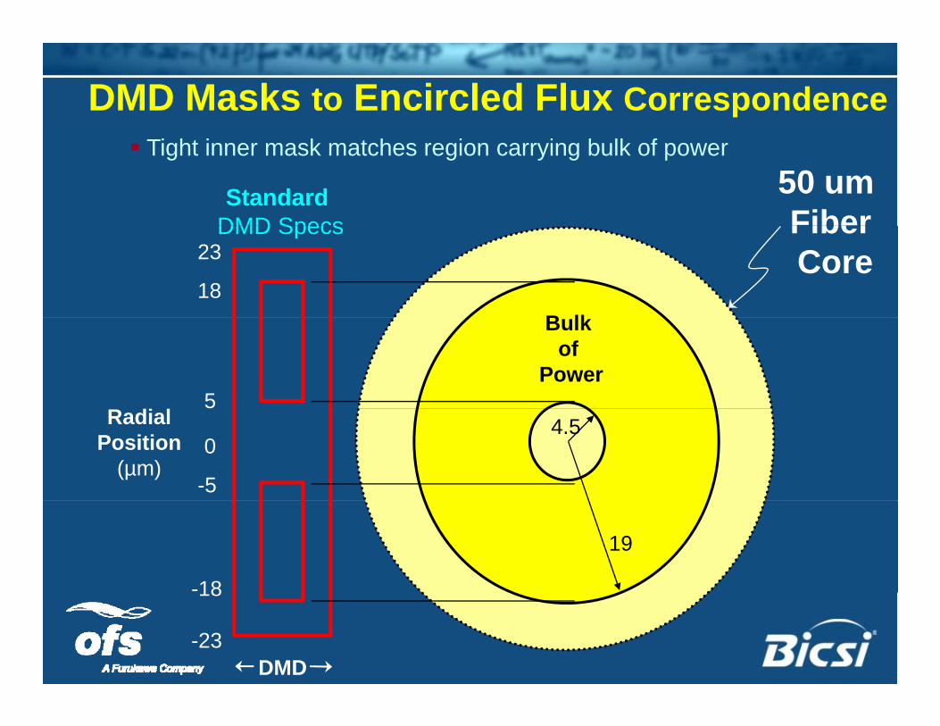
DMD Masks to Encircled Flux Correspondence Tight inner mask matches region carrying bulk of power
Standard DMD Specs
50 um Fiber
18
23
B lk
DMD Specs FiberCore
5R di l
Bulk of
Power
0
-5
4.5RadialPosition
(µm)
-18
19
18
-23DMD
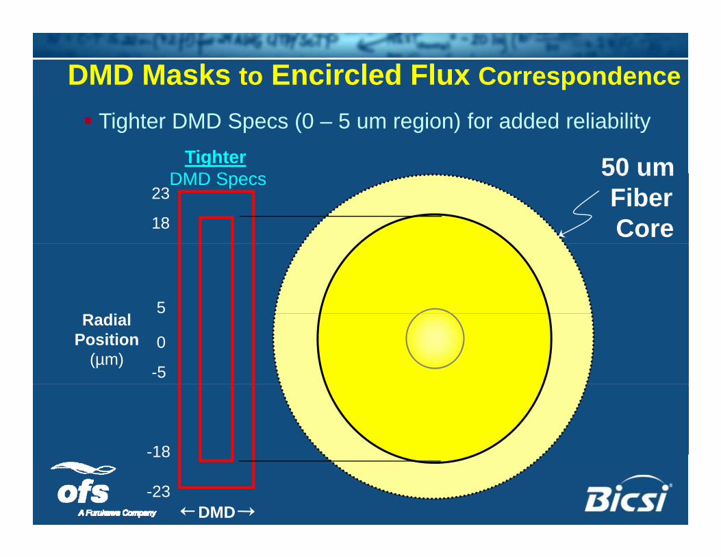
DMD Masks to Encircled Flux Correspondence Tighter DMD Specs (0 – 5 um region) for added reliability
TighterDMD S 50 um
18
23DMD Specs 50 um
FiberCore
5R di l
0
-5
RadialPosition
(µm)
-18
DMD
18
-23
Effective Modal Bandwidth Calculated (EMBc)
(TIA-492AAAC-A, IEC 60793-2-10)
Calculated based on DMD DMD of fiber measured per TIA FOTP-220
Calculated from interaction of the DMD with 10 simulated VCSELsCalculated from interaction of the DMD with 10 simulated VCSELs (weighting functions)
10 VCSELs meant to represent a broad range of compliant VCSEL specifications
The lowest of the 10 bandwidths is EMBc
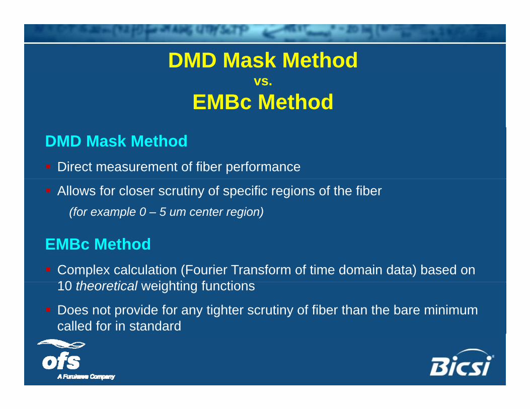
DMD Mask Method vs.
EMBc Method
DMD Mask Method Direct measurement of fiber performance
Allows for closer scrutiny of specific regions of the fiber(for example 0 – 5 um center region)
EMBc Method Complex calculation (Fourier Transform of time domain data) based on
10 th ti l i hti f ti10 theoretical weighting functions
Does not provide for any tighter scrutiny of fiber than the bare minimum called for in standard
Multimode Fiber TypesMultimode Fiber Types
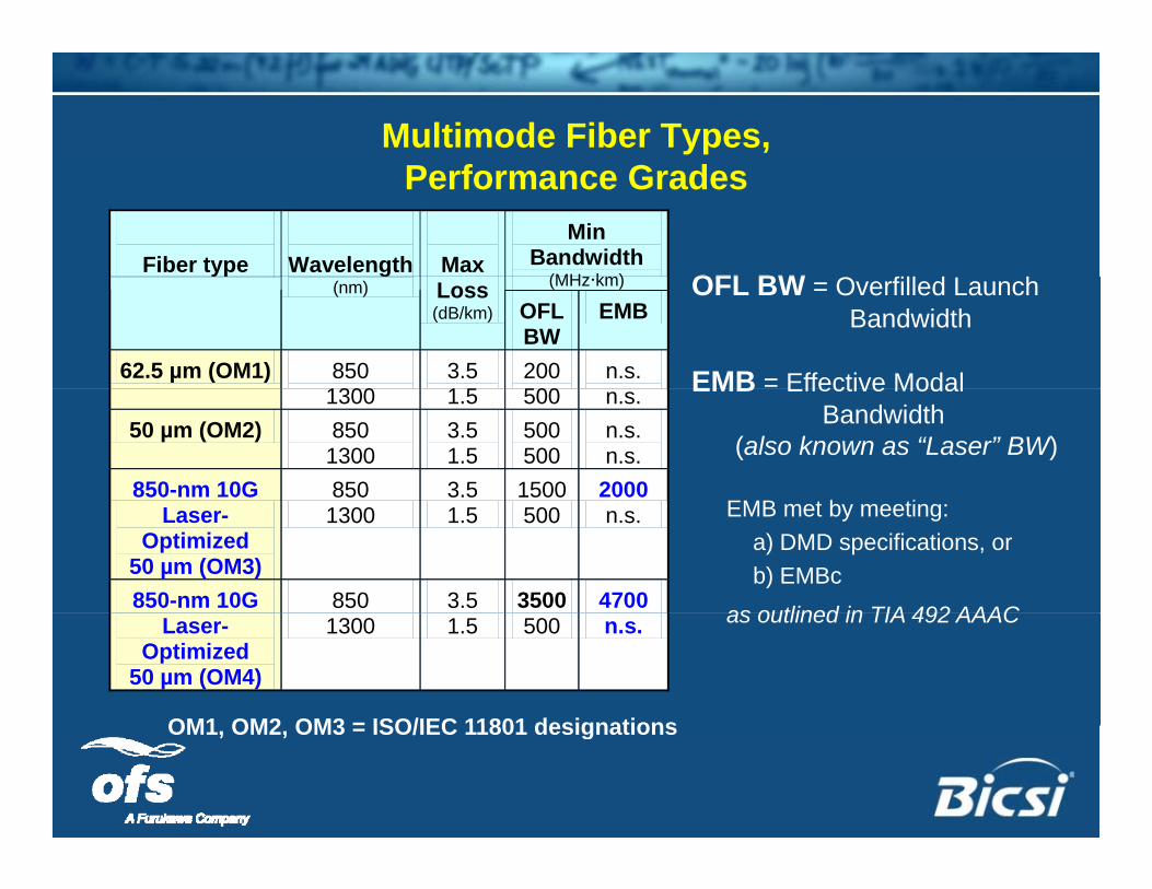
Multimode Fiber Types, P f G dPerformance Grades
Min Bandwidth
(MH k )
Fiber type
Wavelength
Max
OFL BW O fill d L h(MHzkm)y g
(nm) Loss (dB/km) OFL
BW EMB
62.5 µm (OM1) 850 1300
3.5 1 5
200 500
n.s. EMB = Effective Modal
OFL BW = Overfilled Launch Bandwidth
1300 1.5 500 n.s.50 µm (OM2) 850
1300 3.5 1.5
500 500
n.s. n.s.
850-nm 10G 850 3.5 1500 2000
EMB Effective ModalBandwidth
(also known as “Laser” BW)
EMB t b tiLaser-Optimized
50 µm (OM3)
1300 1.5 500 n.s.
850-nm 10G 850 3.5 3500 4700
EMB met by meeting:a) DMD specifications, or b) EMBc
as outlined in TIA 492 AAACLaser-Optimized
50 µm (OM4)
1300 1.5 500 n.s.
OM1 OM2 OM3 = ISO/IEC 11801 designations
as outlined in TIA 492 AAAC
OM1, OM2, OM3 = ISO/IEC 11801 designations
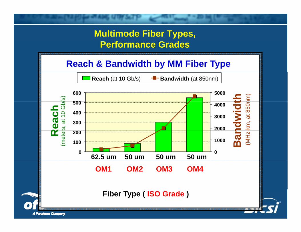
Multimode Fiber Types, Performance GradesPerformance Grades
Reach & Bandwidth by MM Fiber Type
500
600
/s) 5000
th nm)
Reach (at 10 Gb/s) Bandwidth (at 850nm)
200
300
400
500
Rea
chrs
, at 1
0 G
b/
2000
3000
4000
ndw
idt
-km
, at 8
50n
0
100
200
62.5 um 50 um 50 um 50 um
R(m
eter
0
1000 Ban
(MH
z-
OM1 OM2 OM3 OM4
Fiber Type ( ISO Grade )
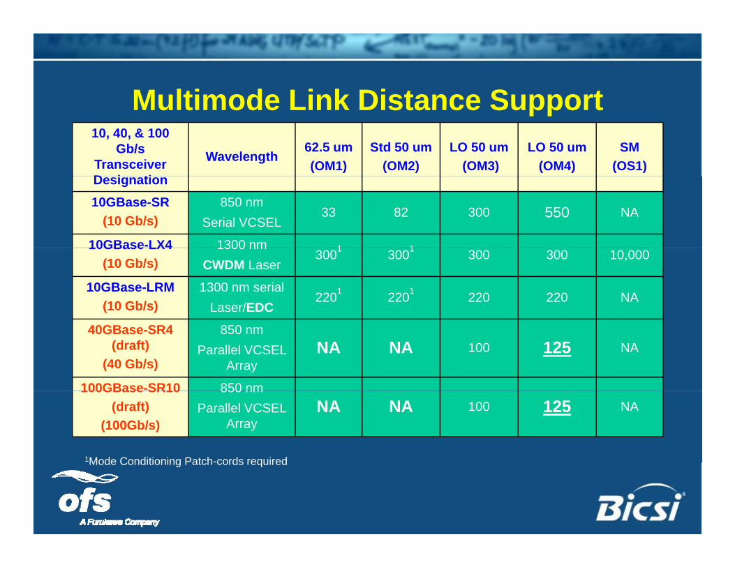
Multimode Link Distance SupportMultimode Link Distance Support10, 40, & 100
Gb/s Transceiver D i ti
Wavelength62.5 um(OM1)
Std 50 um(OM2)
LO 50 um(OM3)
LO 50 um(OM4)
SM(OS1)
Designation10GBase-SR
(10 Gb/s)850 nm
Serial VCSEL33 82 300 550 NA
10GBase-LX4 1300 nm 1 110GBase LX4(10 Gb/s)
1300 nmCWDM Laser
3001 3001 300 300 10,000
10GBase-LRM(10 Gb/s)
1300 nm serialLaser/EDC
2201 2201 220 220 NA
40GBase-SR4 (draft)
(40 Gb/s)
850 nm Parallel VCSEL
ArrayNA NA 100 125 NA
100GBase-SR10 850 nm100GBase SR10(draft)
(100Gb/s)
850 nm Parallel VCSEL
ArrayNA NA 100 125 NA
1Mode Conditioning Patch-cords requiredMode Conditioning Patch-cords required
Outline
• Market Drivers
Outline
Market Drivers
• About Optical Fiber
• OM4 Fiber – What is it?
• OM4 Fiber Standards & Specifications& p
• OM4’s role for 40G & 100G Ethernet
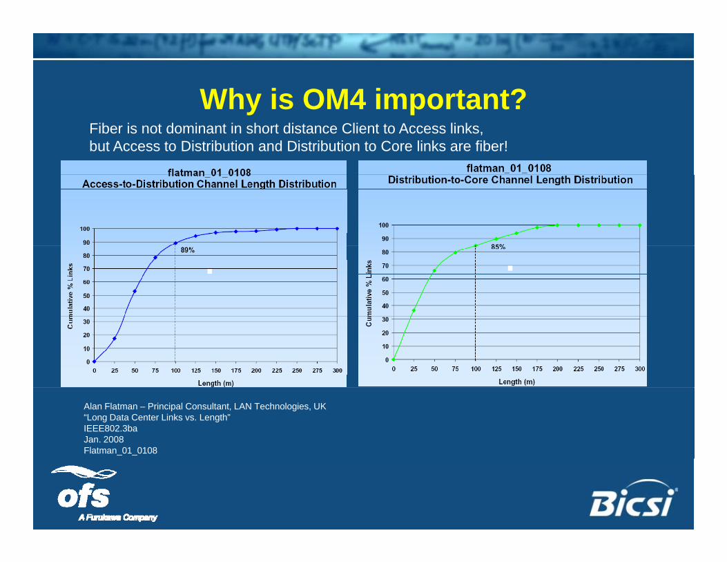
Why is OM4 important?Why is OM4 important?Fiber is not dominant in short distance Client to Access links, but Access to Distribution and Distribution to Core links are fiber!
Alan Flatman – Principal Consultant, LAN Technologies, UK“Long Data Center Links vs. Length”IEEE802.3baJan. 2008Flatman_01_0108
Why is the OM4 standard important?Why is the OM4 standard important?
Gives IEEE 802.3, Fibre Channel and Infiniband input on how a standards defined multimode fiber
ill t ith t ti twill operate with next generation systems.
Outline
• Market Drivers
Outline
Market Drivers
• About Optical Fiber
• OM4 Fiber – What is it?
• OM4 Fiber Standards & Specifications& p
• OM4’s role for 40G & 100G Ethernet

OM4 StandardizationOM4 Standardization
• Specifications agreed upon in both TIA and IEC
– TIA-492AAAD
IEC 60793 2 10 Fiber Type A1a 3– IEC 60793-2-10, Fiber Type A1a.3
General agreement to harmonize the two documents
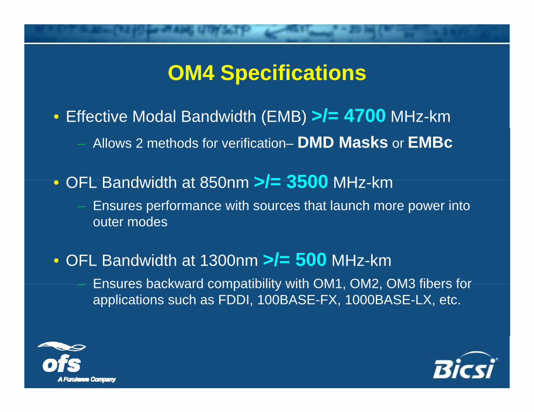
OM4 SpecificationsOM4 Specifications
• Effective Modal Bandwidth (EMB) >/= 4700 MHz-km– Allows 2 methods for verification– DMD Masks or EMBc
OFL Bandwidth at 850nm >/= 3500 MHz km• OFL Bandwidth at 850nm >/= 3500 MHz-km– Ensures performance with sources that launch more power into
outer modes
• OFL Bandwidth at 1300nm >/= 500 MHz-kmEnsures backward compatibility with OM1 OM2 OM3 fibers for– Ensures backward compatibility with OM1, OM2, OM3 fibers for applications such as FDDI, 100BASE-FX, 1000BASE-LX, etc.
Outline
• Market Drivers
Outline
Market Drivers
• About Optical Fiber
• OM4 Fiber – What is it?
• OM4 Fiber Standards & Specifications& p
• OM4’s role for 40G & 100G Ethernet
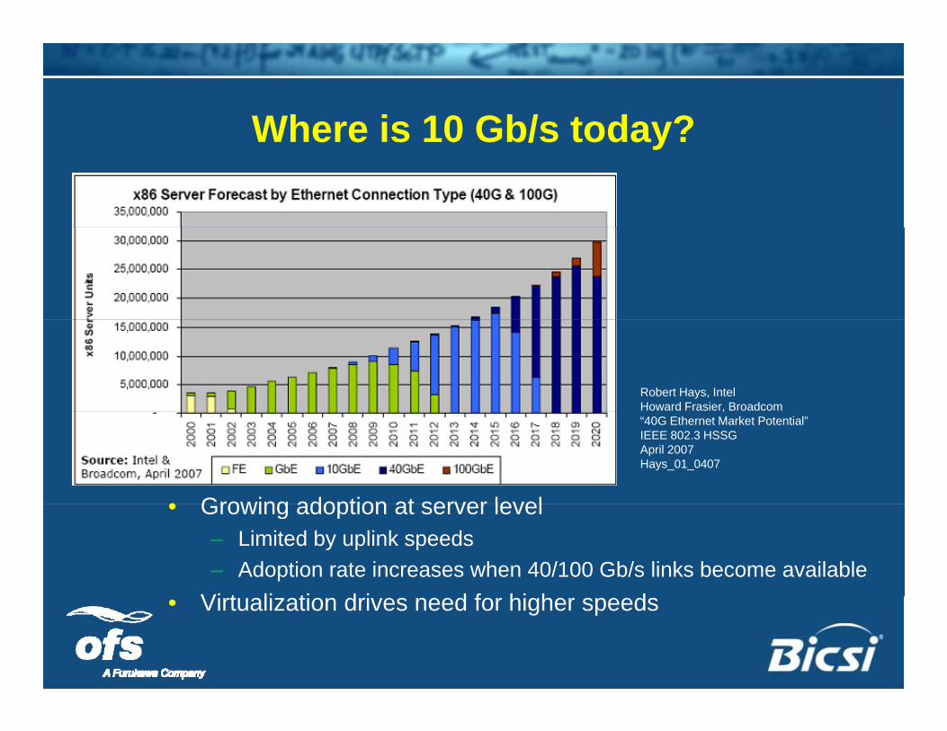
Where is 10 Gb/s today?Where is 10 Gb/s today?
Robert Hays, IntelHoward Frasier, Broadcom,“40G Ethernet Market Potential”IEEE 802.3 HSSGApril 2007Hays_01_0407
• Growing adoption at server level• Growing adoption at server level– Limited by uplink speeds– Adoption rate increases when 40/100 Gb/s links become available
Vi t li ti d i d f hi h d• Virtualization drives need for higher speeds
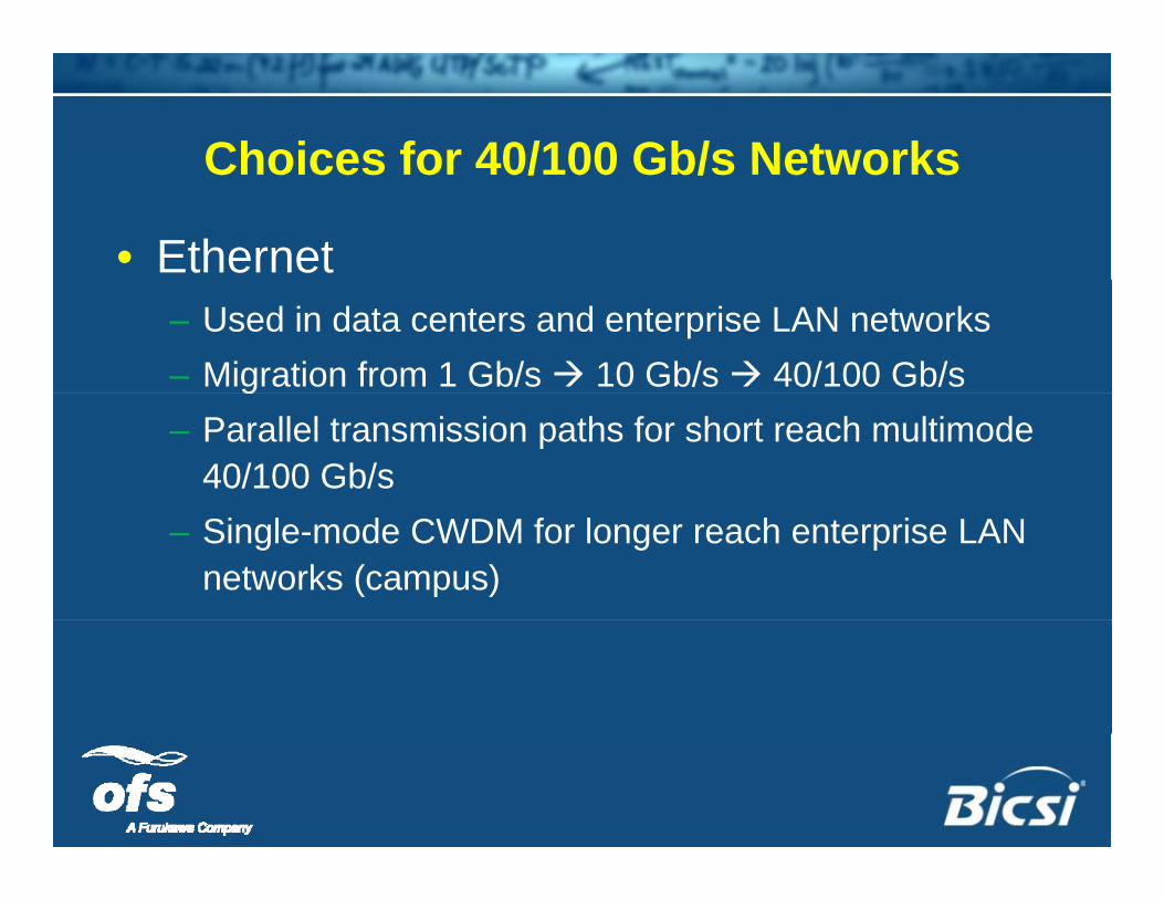
Choices for 40/100 Gb/s NetworksChoices for 40/100 Gb/s Networks
• Ethernet– Used in data centers and enterprise LAN networks– Migration from 1 Gb/s 10 Gb/s 40/100 Gb/s g– Parallel transmission paths for short reach multimode
40/100 Gb/s– Single-mode CWDM for longer reach enterprise LAN
networks (campus)
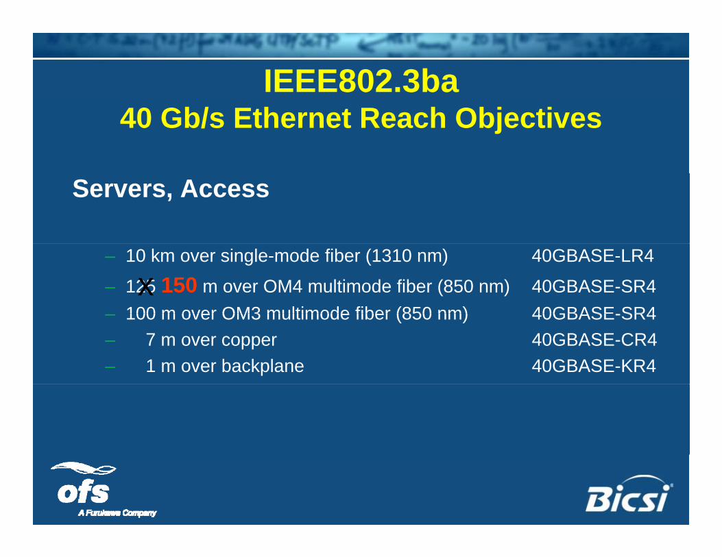
IEEE802.3ba 40 Gb/s Ethernet Reach Objectives
Servers, Access
– 10 km over single-mode fiber (1310 nm) 40GBASE-LR4
– 125 150 m over OM4 multimode fiber (850 nm) 40GBASE-SR4100 m over OM3 multimode fiber (850 nm) 40GBASE SR4x
– 100 m over OM3 multimode fiber (850 nm) 40GBASE-SR4– 7 m over copper 40GBASE-CR4– 1 m over backplane 40GBASE-KR4
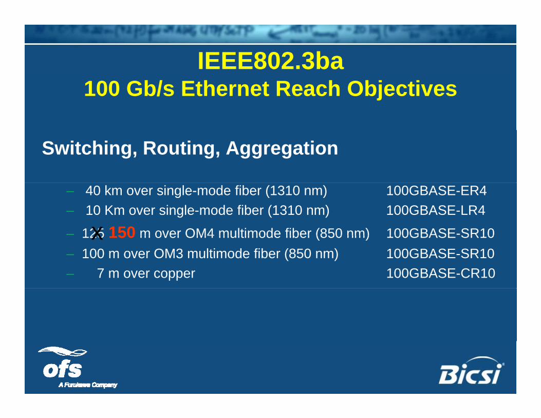
IEEE802.3ba 100 Gb/s Ethernet Reach Objectives
Switching, Routing, Aggregation
– 40 km over single-mode fiber (1310 nm) 100GBASE-ER4– 10 Km over single-mode fiber (1310 nm) 100GBASE-LR4
– 125 150 m over OM4 multimode fiber (850 nm) 100GBASE-SR10x125 150 m over OM4 multimode fiber (850 nm) 100GBASE SR10– 100 m over OM3 multimode fiber (850 nm) 100GBASE-SR10– 7 m over copper 100GBASE-CR10
x
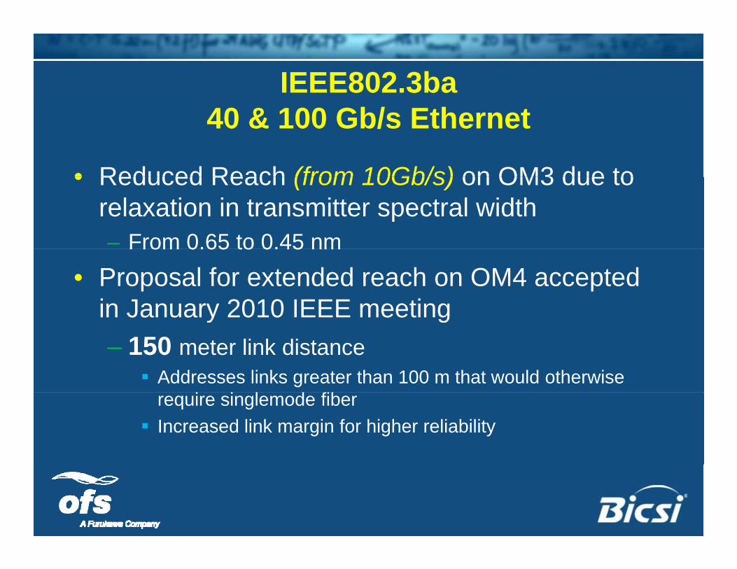
IEEE802.3ba40 & 100 Gb/s Ethernet
• Reduced Reach (from 10Gb/s) on OM3 due to• Reduced Reach (from 10Gb/s) on OM3 due to relaxation in transmitter spectral width– From 0.65 to 0.45 nmFrom 0.65 to 0.45 nm
• Proposal for extended reach on OM4 accepted in January 2010 IEEE meetingy g– 150 meter link distance
Addresses links greater than 100 m that would otherwise frequire singlemode fiber
Increased link margin for higher reliability
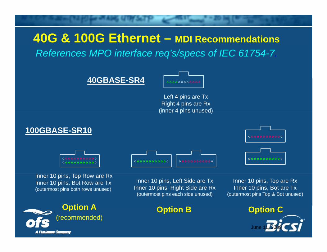
40G & 100G Ethernet – MDI RecommendationsReferences MPO interface req’s/specs of IEC 61754-7.
40GBASE SR440GBASE-SR4 o o o o o o o o o o o o
Left 4 pins are TxRight 4 pins are Rx
(inner 4 pins unused)
100GBASE-SR10o o o o o o o o o o o o
(inner 4 pins unused)
o o o o o o o o o o o oo o o o o o o o o o o o
o o o o o o o o o o o oo o o o o o o o o o o oo o o o o o o o o o o o
I 10 i T R R
Option A
Inner 10 pins, Top Row are RxInner 10 pins, Bot Row are Tx(outermost pins both rows unused)
Inner 10 pins, Left Side are TxInner 10 pins, Right Side are Rx
(outermost pins each side unused)
Inner 10 pins, Top are RxInner 10 pins, Bot are Tx
(outermost pins Top & Bot unused)
Option BOption A(recommended)
Option C
June 11, 2009
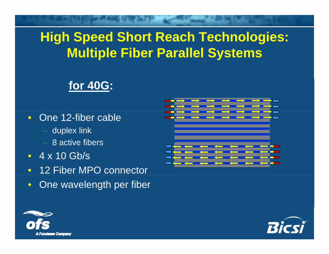
High Speed Short Reach Technologies:Multiple Fiber Parallel Systems
for 40G:
• One 12-fiber cable– duplex link– 8 active fibers– 8 active fibers
• 4 x 10 Gb/s• 12 Fiber MPO connector• One wavelength per fiber
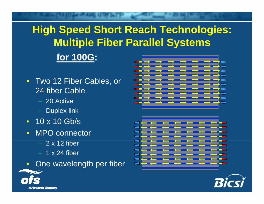
High Speed Short Reach Technologies:Multiple Fiber Parallel Systemsfor 100G:
• Two 12 Fiber Cables, or 24 fiber Cable24 fiber Cable– 20 Active– Duplex link
• 10 x 10 Gb/s• MPO connector
– 2 x 12 fiber– 1 x 24 fiber
• One wavelength per fiberO e a e e gt pe be
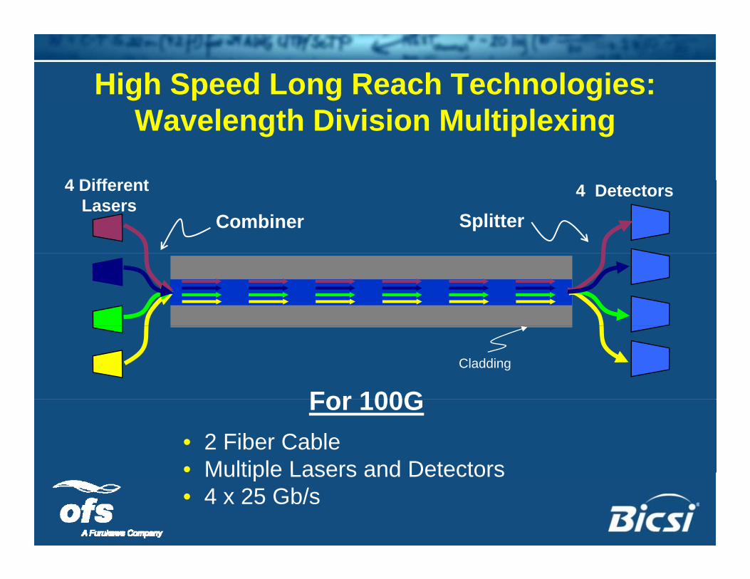
High Speed Long Reach Technologies:
4 Diff t
Wavelength Division Multiplexing
4 Detectors
Splitter
4 Different Lasers
Combiner
Cladding
For 100GFor 100G• 2 Fiber Cable• Multiple Lasers and DetectorsMultiple Lasers and Detectors• 4 x 25 Gb/s
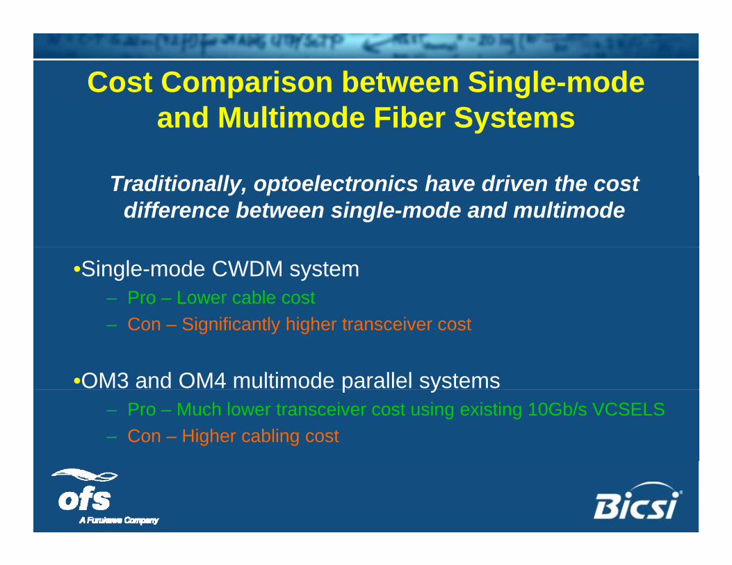
Cost Comparison between Single-mode and Multimode Fiber Systems
T diti ll t l t i h d i th tTraditionally, optoelectronics have driven the cost difference between single-mode and multimode
•Single-mode CWDM system– Pro – Lower cable cost
C Si ifi tl hi h t i t– Con – Significantly higher transceiver cost
•OM3 and OM4 multimode parallel systemsp y– Pro – Much lower transceiver cost using existing 10Gb/s VCSELS– Con – Higher cabling cost
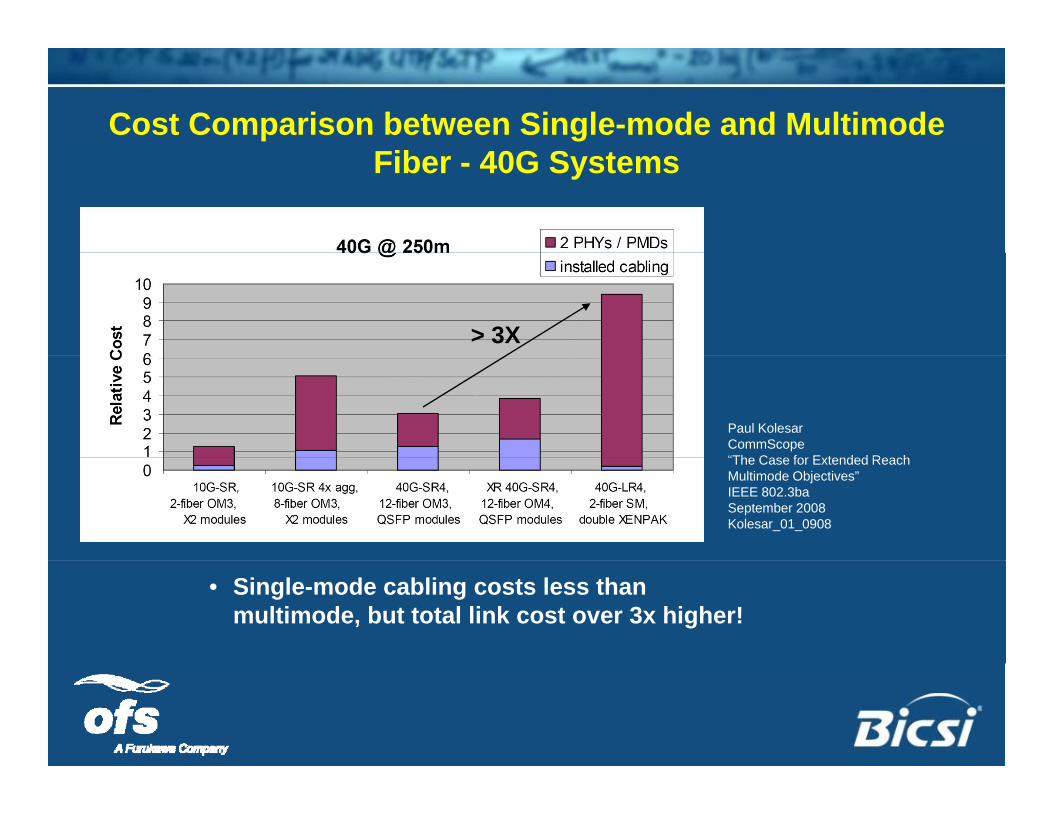
Cost Comparison between Single-mode and Multimode Fib 40G SFiber - 40G Systems
> 3X
Paul KolesarCommScope“The Case for Extended ReachThe Case for Extended Reach Multimode Objectives”IEEE 802.3baSeptember 2008Kolesar_01_0908
• Single-mode cabling costs less than multimode, but total link cost over 3x higher!
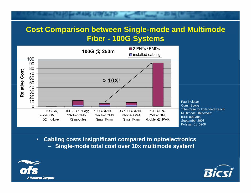
Cost Comparison between Single-mode and Multimode Fib 100G SFiber - 100G Systems
> 10X!
Paul KolesarCommScope“The Case for Extended ReachThe Case for Extended Reach Multimode Objectives”IEEE 802.3baSeptember 2008Kolesar_01_0908
• Cabling costs insignificant compared to optoelectronics– Single-mode total cost over 10x multimode system!
Power ConsumptionPower Consumption• Lower power consumption critical as link density
and speed increase– 10G SFP Fiber transceivers consume <1watt
10GBASE T i– 10GBASE-T copper transceivers can consume >10watts
• Savings ~ 9 watts/transceiverCooling another 9 atts/transcei er• Cooling – another 9 watts/transceiver

Th kThank you…..