om, rider 11, rider 13, rider 11 bio, rider 13 bio, 2002-04 · 2015-02-28 · rider 11 rider 13...
TRANSCRIPT

Operator´s manual
Please read these instructions carefully and make sureyou understand them before using the machine. English
Rider 11 Rider 13Rider 11 Bio Rider 13 Bio

Svenska – 31
Sve-5 225/232/235 Bruk 97-11-25, 08.4631

English – 1
Operator’s Manual forRider 11 and Rider 13
Rider 11 Bio and Rider 13 Bio
CONTENTS
Introduction ......................................................... 2Driving and transport on public roads .............. 2Towing .............................................................. 2Use ................................................................... 2Serial number ................................................... 3
Explanation of symbols ...................................... 4Safety Instructions .............................................. 5
General Use ..................................................... 5Driving on Slopes ............................................. 7Children ............................................................ 8Maintenance .................................................... 8Transport .......................................................... 9
Presentation ...................................................... 11Location of the controls .................................. 11Throttle/Choke lever Rider 11/11 Bio ............. 12Clutch pedal Rider 11/11 Bio .......................... 12Brake pedal/Parking brake Rider 11/11 Bio ... 12Throttle/Choke lever Rider 13/13 Bio ............. 13Speed limiter Rider 13/13 Bio ........................ 13Parking brake Rider 13/13 Bio ....................... 13Cutting unit ..................................................... 14Lift lever for cutting unit .................................. 14Lever for adjustment of cutting height ............ 15Seat ................................................................ 15Fuelling .......................................................... 15
Driving ................................................................ 16Before starting ................................................ 16Starting the engine ......................................... 16Driving the machine ....................................... 16Cutting tips ..................................................... 19Stopping the engine ....................................... 20Drive disengagement lever ............................ 20
Maintenance ...................................................... 21
IMPORTANT INFORMATION
Read through these instructions carefullyso that you know how to use and maintainthe machine before using it.
For servicing other than described in thismanual contact an authorised dealer forparts and service.
Maintenance schedule ................................... 21Dismantling of the machine hoods ................. 22Checking and adjusting the steering wires .... 24Checking and adjusting the brakes ................ 25Checking and adjustment of throttle wire ....... 26Replacement of fuel filter ............................... 26Replacement of air filter ................................. 25Checking the fuel pump’s air filter .................. 28Checking the battery acid level ...................... 28Ignition system ............................................... 28Checking the safety system ........................... 29Checking the tyre pressure ............................ 30Checking the engine’s cooling air intake ........ 30Checking and adjusting the cutting unitground pressure ............................................. 31Checking the parallelism of the cutting unit ... 31Adjusting the parallelism of the cutting unit .... 32Service position for BioClip 90 ....................... 33Checking the blades ...................................... 36Replacing the break-pin ................................. 36Changing the oil ............................................. 37
Lubrication ......................................................... 37Checking the engine’s oil level ....................... 37Checking the transmission’s oil level ............. 38Lubricating the belt adjuster ........................... 38General lubrication ......................................... 38Lubrication of front wheel bearings ................ 39
Trouble shooting schedule .............................. 40Storage ............................................................... 41
Winter storage ................................................ 41Service ........................................................... 41
Technical data ................................................... 42EU declaration of conformity ........................... 44
2 – English
Dear customer
Thank you for choosing a Husqvarna Rider. Husqvarna Riders are built to a unique design with a front-mounted cutting unit and a patented rear-wheel steering system. Riders are designed for maximumefficiency even in small or confined areas. The closely grouped controls and pedal-operated hydrostatictransmission (certain models) also contribute to the performance of this machine.
We hope you will find this operator’s manual very useful. By following its instructions (on operation, service,maintenance, etc.) you will significantly extend the life of the machine and even its second-hand value.
When you sell your Rider, make sure you pass on the operator’s manual to the new owner.
Travel and transport on public roads
Check the relevant road traffic regulations before driving the machine on a public road. If transporting themachine on another vehicle always use approved securing devices and make sure that the machine issecurely held.
Towing
When your machine is equipped with a hydrostatic transmission you should, if necessary, only tow themachine over short distances and at a low speed, otherwise there is a risk of damaging the transmission.
Intended use
This machine is designed solely for cutting grass on conventional lawns and other cleared and leveledground without obstacles, as rocks, stumps etc., and, in conjunction with accessories supplied by themanufacturer even for other special tasks for which instructions are delivered with the accessory. Use inany other way is considered as contrary to the intended use. Compliance with and strict adherence to theconditions of operation, service and repair as specified by the manufacturer also constitute essentialelements of the intended use.
This machine should be operated, serviced and repaired only by persons who are familiar with its particularcharacteristics and who are acquainted with the relevant safety procedures.
Accident prevention regulations, all other generally recognised regulations on safety and occupationalmedicine, and all road traffic regulations must be observed at all times.
Any arbitrary modifications carried out to this machine may relieve the manufacturer of liability for anyresulting damage or injury
INTRODUKTION
English – 3
Good service
Husqvarna products are sold all over the world and only through servicing dealers. This is to ensure thatyou, the customer, get the best support and service. Before the machine is delivered it undergoesinspection and is adjusted by your dealer.
When you need spare parts or advice on service issues, warranty terms, etc., contact:
This Operator’s Manual belongs to machine with serial number:
SAFETY INSTRUCTIONS
Serial number
The serial number can be found on the printed plate attached to the front, left-hand side under the seat.Stated on the plate, from the top are:
• The machines type designation.
• The manufacturer’s type number.
• The machine’s serial number.
State the type designation and serial number when ordering spare parts.
The engine number is punched on a plate that is riveted to the fan cover. The plate states:
• Model.
• Type.
• Code.
Please state these when ordering spare parts.
The transmission’s serial number on hydrostatic machines is stated on the barcode decal located on thefront of the housing on the left-hand drive axle:
• Type designation is stated above the barcode and starts with the letter ”K”.
• The serial number is stated above the barcode and has the prefix ”s/n”.
• The manufacturer’s type number is stated under the barcode and has the prefix ”p/n”.
State the type designation and serial number when ordering spare parts.
Engine Transmission
4 – English
NR
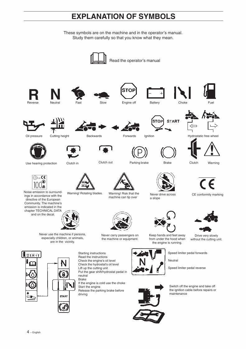
These symbols are on the machine and in the operator’s manual.Study them carefully so that you know what they mean.
Read the operator’s manual
Reverse Neutral Fast Slow Engine off Battery Choke Fuel
Oil pressure Cutting height Backwards Forwards Ignition Hydrostatic free wheel
Use hearing protection
EXPLANATION OF SYMBOLS
Never use the machine if persons,especially children, or animals,
are in the vicinity.
Never carry passengers onthe machine or equipment.
Starting instructionsRead the instructionsCheck the engine’s oil levelCheck the hydrostat’s oil levelLift up the cutting unitPut the gear shift/hydrostat pedal inneutralBrakeIf the engine is cold use the chokeStart the engineRelease the parking brake beforedriving
Drive very slowlywithout the cutting unit.
Keep hands and feet awayfrom under the hood when
the engine is running.
Speed limiter pedal forwards
Neutral
Speed limiter pedal reverse
Switch off the engine and take offthe ignition cable before repairs ormaintenance
CE conformity markingWarning! Rotating blades. Warning! Risk that themachine can tip over
Never drive acrossa slope
Noise emission to surround-ings in accordance with thedirective of the European
Community. The machine’semission is indicated in thechapter TECHNICAL DATA
and on the decal.
WarningClutchBrakeParking brake Clutch outClutch in
English – 5
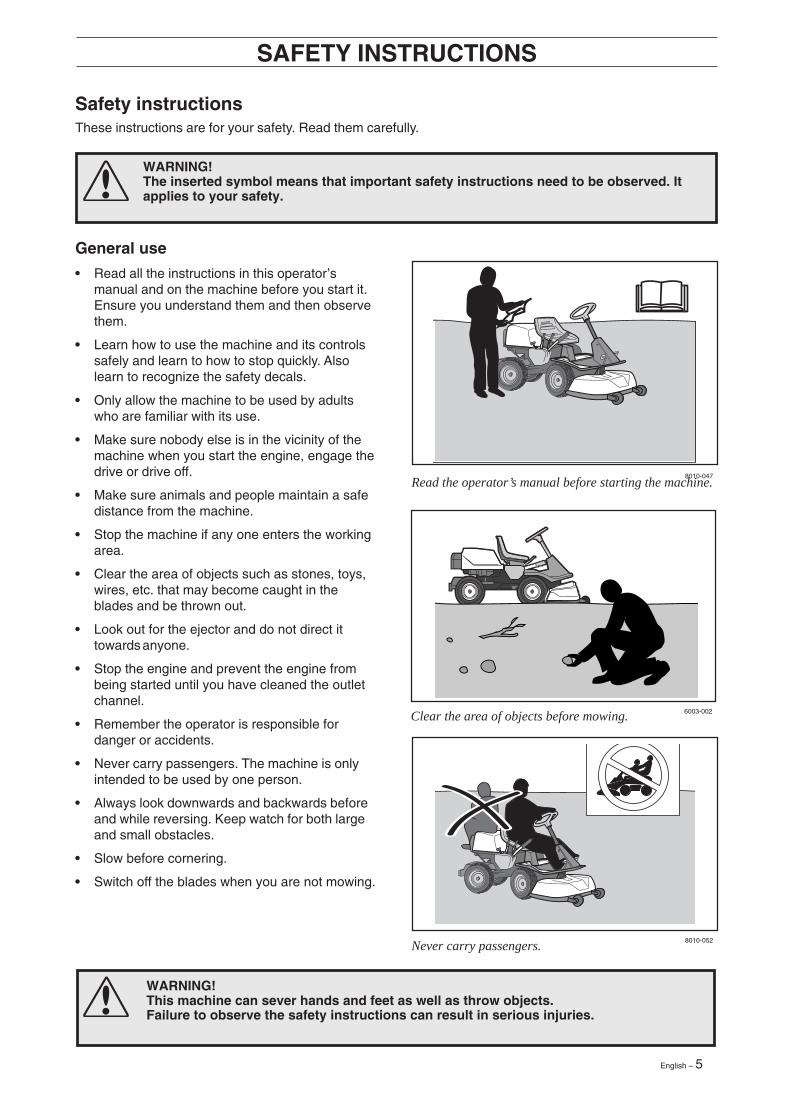
Never carry passengers.
Read the operator’s manual before starting the machine.
Clear the area of objects before mowing.
Safety instructions
General use
• Read all the instructions in this operator’smanual and on the machine before you start it.Ensure you understand them and then observethem.
• Learn how to use the machine and its controlssafely and learn to how to stop quickly. Alsolearn to recognize the safety decals.
• Only allow the machine to be used by adultswho are familiar with its use.
• Make sure nobody else is in the vicinity of themachine when you start the engine, engage thedrive or drive off.
• Make sure animals and people maintain a safedistance from the machine.
• Stop the machine if any one enters the workingarea.
• Clear the area of objects such as stones, toys,wires, etc. that may become caught in theblades and be thrown out.
• Look out for the ejector and do not direct ittowards anyone.
• Stop the engine and prevent the engine frombeing started until you have cleaned the outletchannel.
• Remember the operator is responsible fordanger or accidents.
• Never carry passengers. The machine is onlyintended to be used by one person.
• Always look downwards and backwards beforeand while reversing. Keep watch for both largeand small obstacles.
• Slow before cornering.
• Switch off the blades when you are not mowing.
SAFETY INSTRUCTIONS
WARNING!This machine can sever hands and feet as well as throw objects.Failure to observe the safety instructions can result in serious injuries.
WARNING!The inserted symbol means that important safety instructions need to be observed. Itapplies to your safety.
8010-047
6003-002
8010-052
These instructions are for your safety. Read them carefully.
6 – English
6003-006
8011-292
WARNING!You must use approved personal protective equipment whenever you use the ma-chine. Personal protective equipment cannot eliminate the risk of injury but it willreduce the degree of injury if an accident does happen. Ask your dealer for help inchoosing the right equipment.
• Take care when rounding a fixed object, so thatthe blades do not hit it. Never run the machineover foreign objects.
• Only use the machine in daylight or in otherwell-lit conditions. Keep the machine at a safedistance from holes or other irregularities in theground. Pay attention to other possible risks.
• Never use the machine if you are tired, if youhave consumed alcohol, or if you are takingother drugs or medication that can affect yourvision, judgment or co-ordination.
• Keep an eye on the traffic when working close toa road or when crossing it.
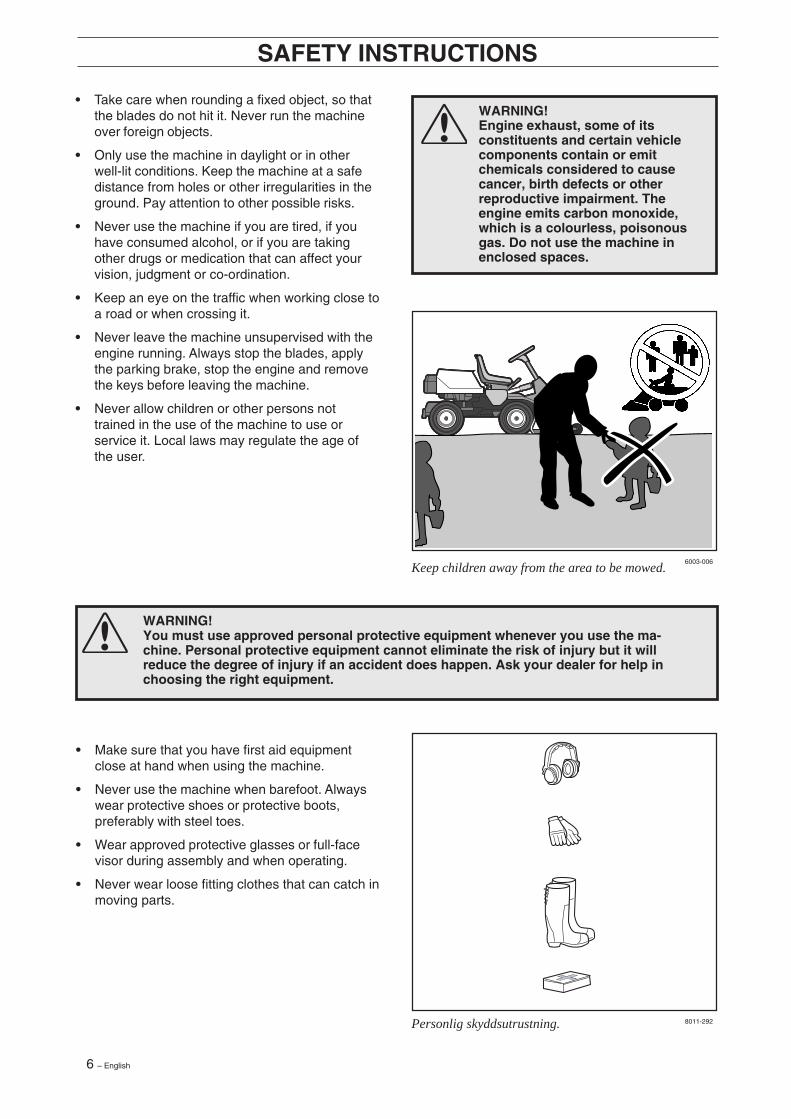
• Never leave the machine unsupervised with theengine running. Always stop the blades, applythe parking brake, stop the engine and removethe keys before leaving the machine.
• Never allow children or other persons nottrained in the use of the machine to use orservice it. Local laws may regulate the age ofthe user.
SAFETY INSTRUCTIONS
WARNING!Engine exhaust, some of itsconstituents and certain vehiclecomponents contain or emitchemicals considered to causecancer, birth defects or otherreproductive impairment. Theengine emits carbon monoxide,which is a colourless, poisonousgas. Do not use the machine inenclosed spaces.
• Make sure that you have first aid equipmentclose at hand when using the machine.
• Never use the machine when barefoot. Alwayswear protective shoes or protective boots,preferably with steel toes.
• Wear approved protective glasses or full-facevisor during assembly and when operating.
• Never wear loose fitting clothes that can catch inmoving parts.
Keep children away from the area to be mowed.
Personlig skyddsutrustning.
English – 7
8010-054
6003-004
Be especially careful when driving on slopes.
Driving on slopes
Driving on slopes is one of the operations wherethe risk of the driver losing control of the machine orof it overturning is the greatest; this can result inserious injury or death. All slopes demand extracare. If you cannot reverse up a slope or if you feelunsure, do not mow it.
Proceed as follows:
• Remove obstacles such as stones, branches,etc.
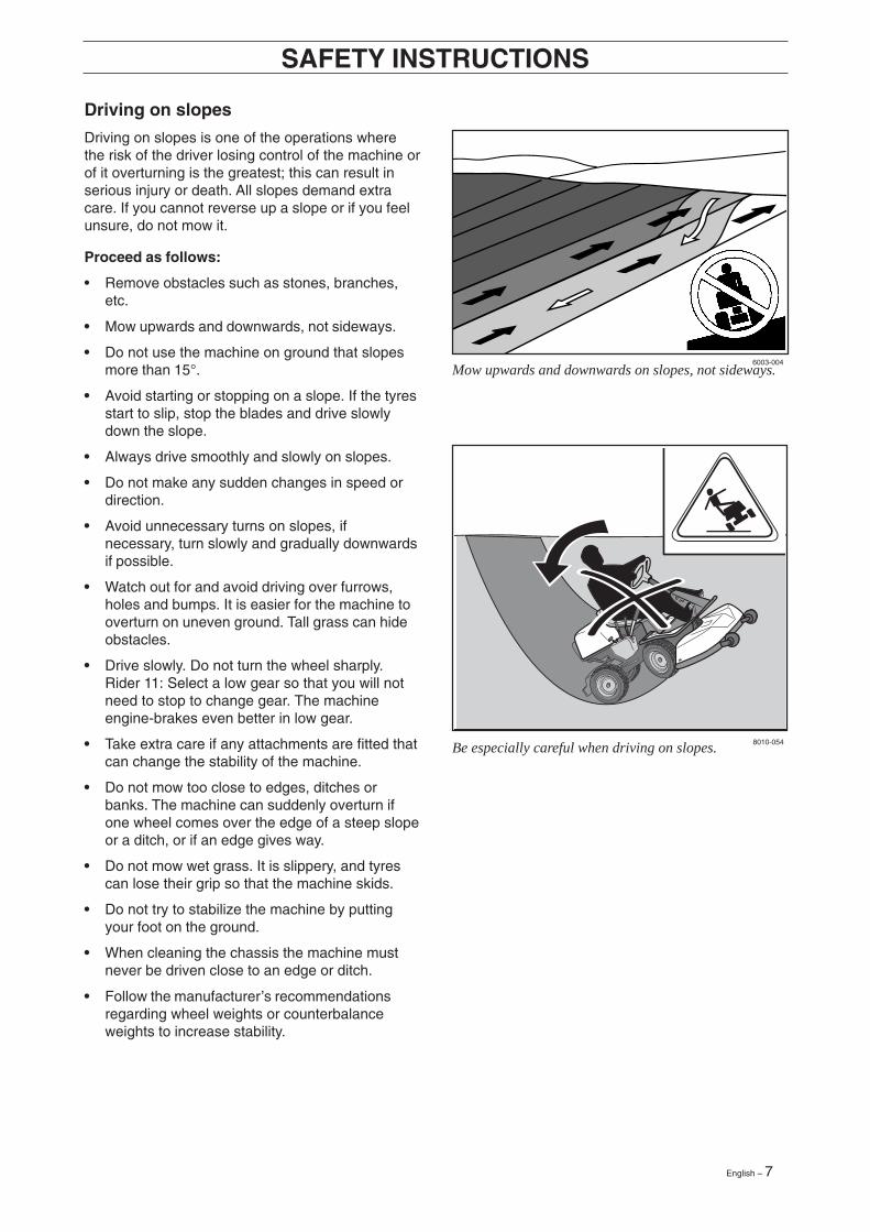
• Mow upwards and downwards, not sideways.
• Do not use the machine on ground that slopesmore than 15°.
• Avoid starting or stopping on a slope. If the tyresstart to slip, stop the blades and drive slowlydown the slope.
• Always drive smoothly and slowly on slopes.
• Do not make any sudden changes in speed ordirection.
• Avoid unnecessary turns on slopes, ifnecessary, turn slowly and gradually downwardsif possible.
• Watch out for and avoid driving over furrows,holes and bumps. It is easier for the machine tooverturn on uneven ground. Tall grass can hideobstacles.
• Drive slowly. Do not turn the wheel sharply.Rider 11: Select a low gear so that you will notneed to stop to change gear. The machineengine-brakes even better in low gear.
• Take extra care if any attachments are fitted thatcan change the stability of the machine.
• Do not mow too close to edges, ditches orbanks. The machine can suddenly overturn ifone wheel comes over the edge of a steep slopeor a ditch, or if an edge gives way.
• Do not mow wet grass. It is slippery, and tyrescan lose their grip so that the machine skids.
• Do not try to stabilize the machine by puttingyour foot on the ground.
• When cleaning the chassis the machine mustnever be driven close to an edge or ditch.
• Follow the manufacturer’s recommendationsregarding wheel weights or counterbalanceweights to increase stability.
SAFETY INSTRUCTIONS
Mow upwards and downwards on slopes, not sideways.

8 – English
8010-057
8010-058
Children
• Serious accidents may occur if you fail to be onyour guard for children in the vicinity of themachine. Children are often attracted to themachine and mowing. Never assume thatchildren will remain where you last saw them.
• Keep children away from the area to be mowedand under close supervision by another adult.
• Keep an eye out and shut off the machine ifchildren enter the work area.
• Before and during reversing procedures, lookbehind you and down for small children.
• Never allow children to ride along. They can falloff and seriously injure themselves or be in theway for safe manoeuvring of the machine.
• Never allow children to operate the machine.
• Be particularly careful near corners, bushes,trees or other objects that block your view.
SAFETY INSTRUCTIONS
Never allow children to operate the machine.
Never fill the fuel tank indoors.
Maintenance
• Stop the engine. Prevent starting by removingthe ignition cable from the spark plug or removethe ignition key before making any adjustmentsor carrying out maintenance.
• Never fill the fuel tank indoors.
• Petrol and petrol fumes are poisonous andextremely flammable. Be especially careful whenhandling petrol, as carelessness can result inpersonal injury or fire.
• Only store fuel in containers approved for thepurpose.
• Never remove the fuel cap and fill the petrol tankwhile the engine is running.
• Allow the engine to cool before refuelling. Do notsmoke. Do not fill petrol in the vicinity of sparksor naked flames.
English – 9
6003-009
WARNING!The engine and the exhaustsystem become very hot duringoperation.Risk of burn injuries if touched.
WARNING!The battery contains lead and leadpollutants, chemicals that areconsidered to cause cancer,birth defects or other reproductiveimpairment. Wash your handsafter touching the battery.
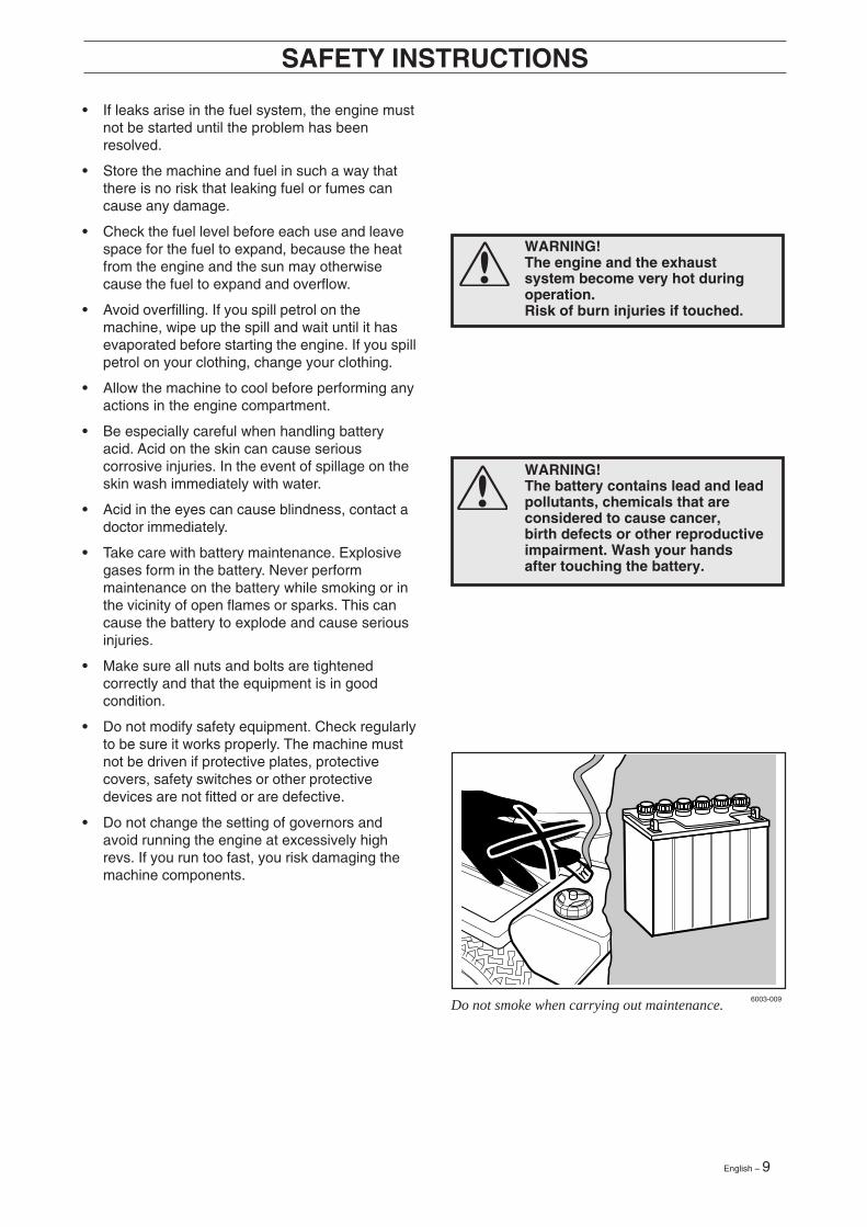
Do not smoke when carrying out maintenance.
• If leaks arise in the fuel system, the engine mustnot be started until the problem has beenresolved.
• Store the machine and fuel in such a way thatthere is no risk that leaking fuel or fumes cancause any damage.
• Check the fuel level before each use and leavespace for the fuel to expand, because the heatfrom the engine and the sun may otherwisecause the fuel to expand and overflow.
• Avoid overfilling. If you spill petrol on themachine, wipe up the spill and wait until it hasevaporated before starting the engine. If you spillpetrol on your clothing, change your clothing.
• Allow the machine to cool before performing anyactions in the engine compartment.
• Be especially careful when handling batteryacid. Acid on the skin can cause seriouscorrosive injuries. In the event of spillage on theskin wash immediately with water.
• Acid in the eyes can cause blindness, contact adoctor immediately.
• Take care with battery maintenance. Explosivegases form in the battery. Never performmaintenance on the battery while smoking or inthe vicinity of open flames or sparks. This cancause the battery to explode and cause seriousinjuries.
• Make sure all nuts and bolts are tightenedcorrectly and that the equipment is in goodcondition.
• Do not modify safety equipment. Check regularlyto be sure it works properly. The machine mustnot be driven if protective plates, protectivecovers, safety switches or other protectivedevices are not fitted or are defective.
• Do not change the setting of governors andavoid running the engine at excessively highrevs. If you run too fast, you risk damaging themachine components.
SAFETY INSTRUCTIONS
10 – English
8010-060
8010-061
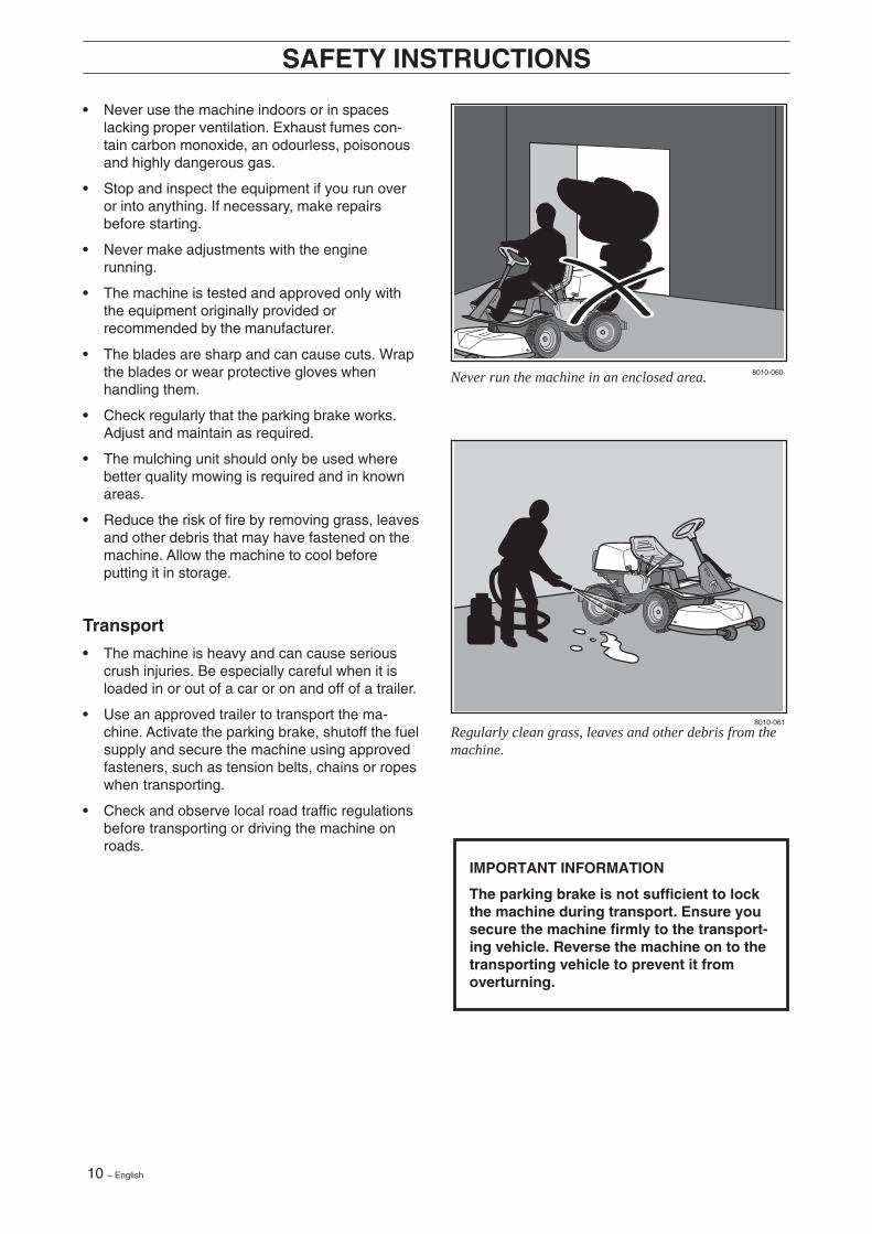
Never run the machine in an enclosed area.
Regularly clean grass, leaves and other debris from themachine.
SAFETY INSTRUCTIONS
• Never use the machine indoors or in spaceslacking proper ventilation. Exhaust fumes con-tain carbon monoxide, an odourless, poisonousand highly dangerous gas.
• Stop and inspect the equipment if you run overor into anything. If necessary, make repairsbefore starting.
• Never make adjustments with the enginerunning.
• The machine is tested and approved only withthe equipment originally provided orrecommended by the manufacturer.
• The blades are sharp and can cause cuts. Wrapthe blades or wear protective gloves whenhandling them.
• Check regularly that the parking brake works.Adjust and maintain as required.
• The mulching unit should only be used wherebetter quality mowing is required and in knownareas.
• Reduce the risk of fire by removing grass, leavesand other debris that may have fastened on themachine. Allow the machine to cool beforeputting it in storage.
Transport
• The machine is heavy and can cause seriouscrush injuries. Be especially careful when it isloaded in or out of a car or on and off of a trailer.
• Use an approved trailer to transport the ma-chine. Activate the parking brake, shutoff the fuelsupply and secure the machine using approvedfasteners, such as tension belts, chains or ropeswhen transporting.
• Check and observe local road traffic regulationsbefore transporting or driving the machine onroads.
IMPORTANT INFORMATION
The parking brake is not sufficient to lockthe machine during transport. Ensure yousecure the machine firmly to the transport-ing vehicle. Reverse the machine on to thetransporting vehicle to prevent it fromoverturning.
English – 11
46 5
7 8 9 10 11
3 13 2 1
12
6004-001Hy 6017-213
6017-238
PRESENTATION
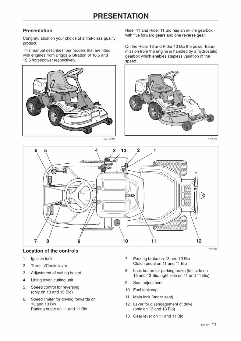
Presentation
Congratulation on your choice of a first-class qualityproduct.
This manual describes four models that are fittedwith engines from Briggs & Stratton of 10.5 and12.5 horsepower respectively.
Rider 11 and Rider 11 Bio has an in-line gearboxwith five forward gears and one reverse gear.
On the Rider 13 and Rider 13 Bio the power trans-mission from the engine is handled by a hydrostaticgearbox which enables stepless variation of thespeed.
Location of the controls
1. Ignition lock
2. Throttle/Choke lever
3. Adjustment of cutting height
4. Lifting lever, cutting unit
5. Speed control for reversing(only on 13 and 13 Bio)
6. Speed limiter for driving forwards on13 and 13 BioParking brake on 11 and 11 Bio
7. Parking brake on 13 and 13 BioClutch pedal on 11 and 11 Bio
8. Lock button for parking brake (left side on13 and 13 Bio, right side on 11 and 11 Bio)
9. Seat adjustment
10. Fuel tank cap
11. Main lock (under seat)
12. Lever for disengagement of drive(only on 13 and 13 Bio)
13. Gear lever on 11 and 11 Bio
12 – English
6004-004
6004-005
6004-006
PRESENTATION RIDER 11 / 11 BIO
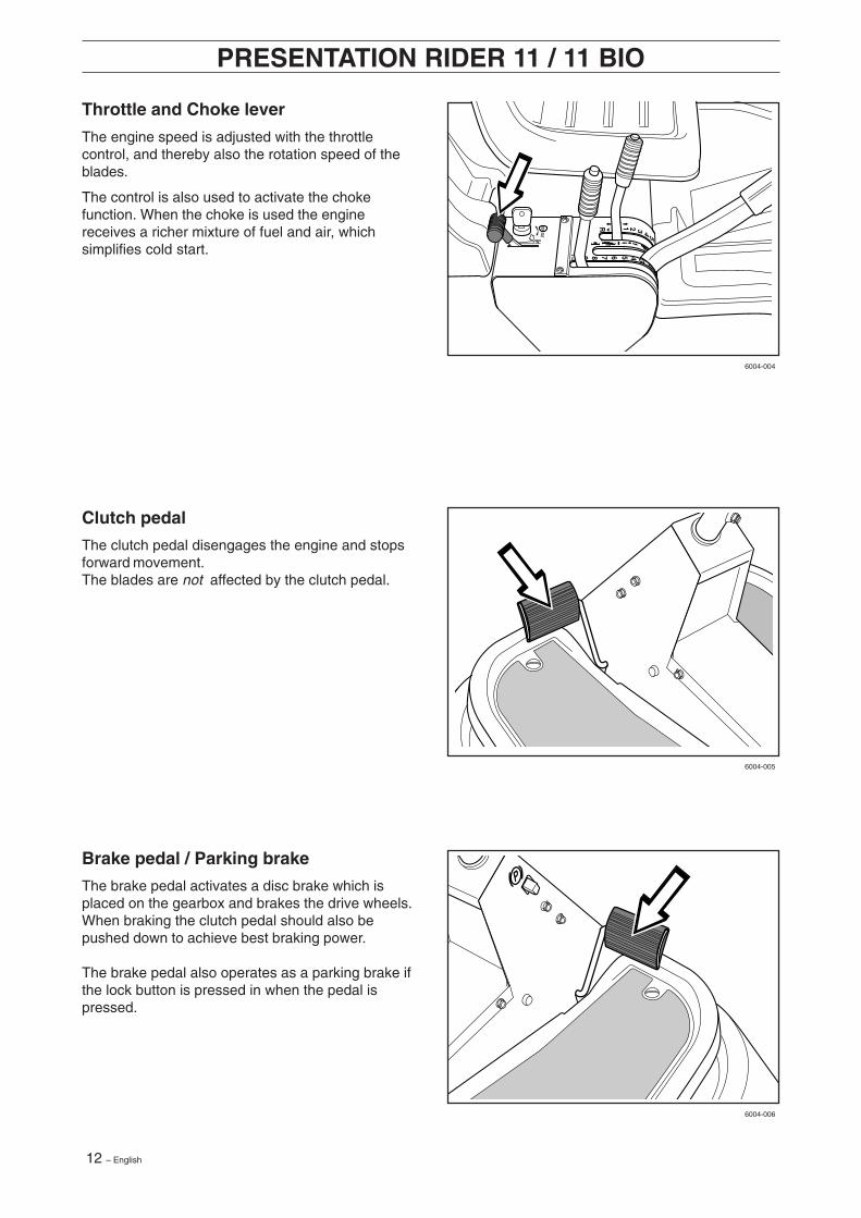
Throttle and Choke lever
The engine speed is adjusted with the throttlecontrol, and thereby also the rotation speed of theblades.
The control is also used to activate the chokefunction. When the choke is used the enginereceives a richer mixture of fuel and air, whichsimplifies cold start.
Clutch pedal
The clutch pedal disengages the engine and stopsforward movement.The blades are not affected by the clutch pedal.
Brake pedal / Parking brake
The brake pedal activates a disc brake which isplaced on the gearbox and brakes the drive wheels.When braking the clutch pedal should also bepushed down to achieve best braking power.
The brake pedal also operates as a parking brake ifthe lock button is pressed in when the pedal ispressed.
English – 13
2 1
6004-004H
6007-017Hy
6004-006H
PRESENTATION RIDER 13/13 BIO
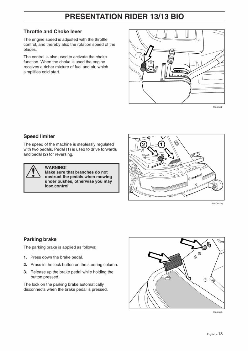
Parking brake
The parking brake is applied as follows:
1. Press down the brake pedal.
2. Press in the lock button on the steering column.
3. Release up the brake pedal while holding thebutton pressed.
The lock on the parking brake automaticallydisconnects when the brake pedal is pressed.
Throttle and Choke lever
The engine speed is adjusted with the throttlecontrol, and thereby also the rotation speed of theblades.
The control is also used to activate the chokefunction. When the choke is used the enginereceives a richer mixture of fuel and air, whichsimplifies cold start.
Speed limiter
The speed of the machine is steplessly regulatedwith two pedals. Pedal (1) is used to drive forwardsand pedal (2) for reversing.
WARNING!Make sure that branches do notobstruct the pedals when mowingunder bushes, otherwise you maylose control.
14 – English
6004-009Hy
6017-214
PRESENTATION
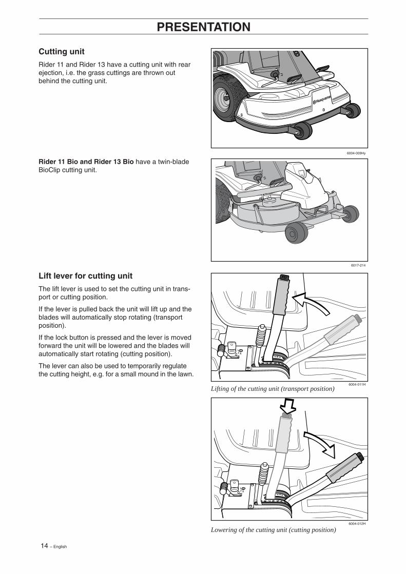
Lift lever for cutting unit
The lift lever is used to set the cutting unit in trans-port or cutting position.
If the lever is pulled back the unit will lift up and theblades will automatically stop rotating (transportposition).
If the lock button is pressed and the lever is movedforward the unit will be lowered and the blades willautomatically start rotating (cutting position).
The lever can also be used to temporarily regulatethe cutting height, e.g. for a small mound in the lawn.
Cutting unit
Rider 11 and Rider 13 have a cutting unit with rearejection, i.e. the grass cuttings are thrown outbehind the cutting unit.
Rider 11 Bio and Rider 13 Bio have a twin-bladeBioClip cutting unit.
6004-012H
6004-011H
Lifting of the cutting unit (transport position)
Lowering of the cutting unit (cutting position)
English – 15
Rider 13 H 6004-013H
6004-014
6004-015
PRESENTATION
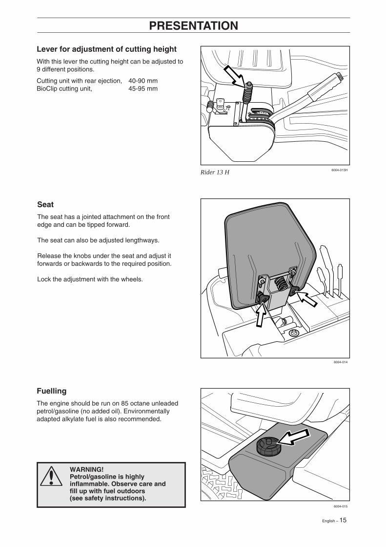
Lever for adjustment of cutting height
With this lever the cutting height can be adjusted to9 different positions.
Cutting unit with rear ejection, 40-90 mmBioClip cutting unit, 45-95 mm
Seat
The seat has a jointed attachment on the frontedge and can be tipped forward.
The seat can also be adjusted lengthways.
Release the knobs under the seat and adjust itforwards or backwards to the required position.
Lock the adjustment with the wheels.
WARNING!Petrol/gasoline is highlyinflammable. Observe care andfill up with fuel outdoors(see safety instructions).
Fuelling
The engine should be run on 85 octane unleadedpetrol/gasoline (no added oil). Environmentallyadapted alkylate fuel is also recommended.
16 – English
1
2
N
Rider 13
Rider 11
6007-001H
6007-002H
6007-003
DRIVING
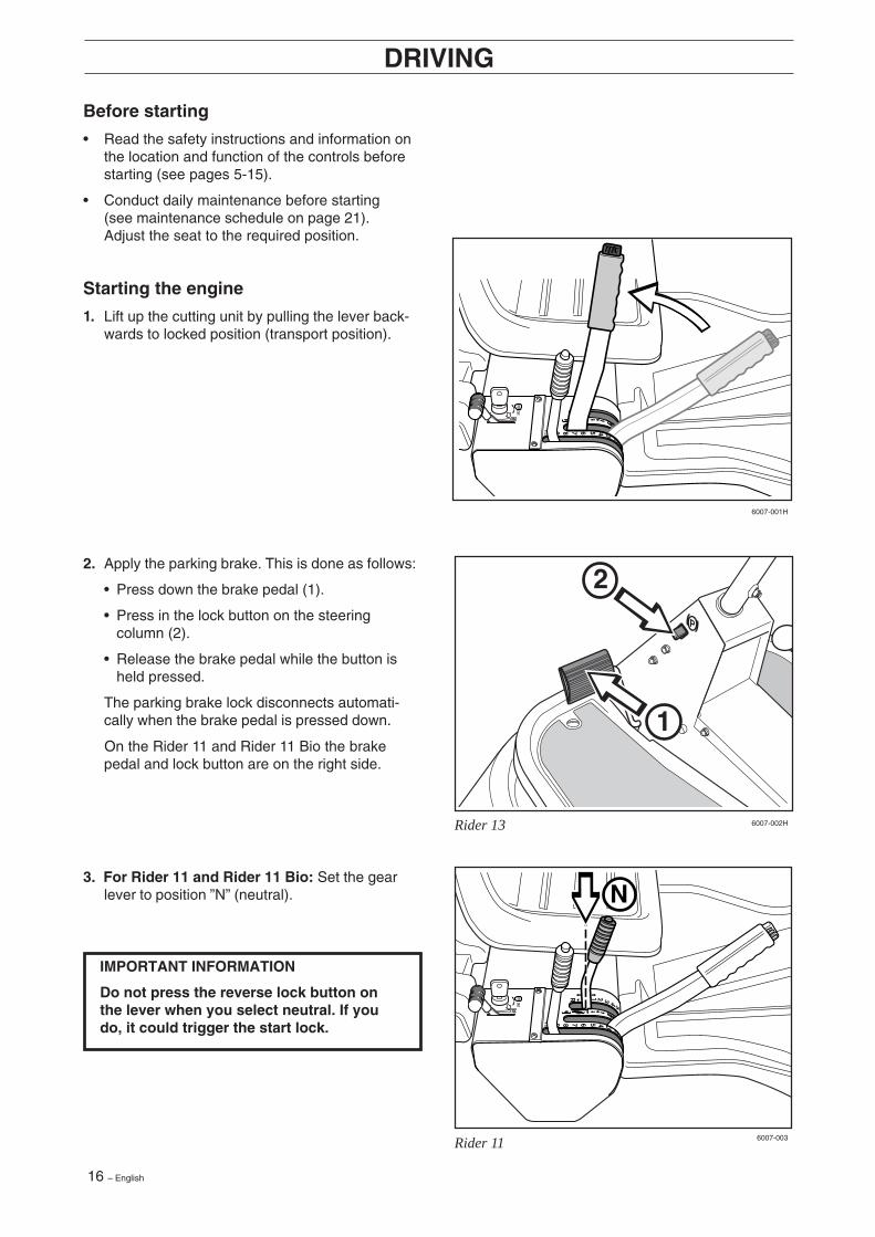
3. For Rider 11 and Rider 11 Bio: Set the gearlever to position ”N” (neutral).
2. Apply the parking brake. This is done as follows:
• Press down the brake pedal (1).
• Press in the lock button on the steeringcolumn (2).
• Release the brake pedal while the button isheld pressed.
The parking brake lock disconnects automati-cally when the brake pedal is pressed down.
On the Rider 11 and Rider 11 Bio the brakepedal and lock button are on the right side.
Before starting
• Read the safety instructions and information onthe location and function of the controls beforestarting (see pages 5-15).
• Conduct daily maintenance before starting(see maintenance schedule on page 21).Adjust the seat to the required position.
Starting the engine
1. Lift up the cutting unit by pulling the lever back-wards to locked position (transport position).
IMPORTANT INFORMATION
Do not press the reverse lock button onthe lever when you select neutral. If youdo, it could trigger the start lock.
English – 17
12
3
STOP START
12
3
6007-004H
6007-005H
6007-006
DRIVING
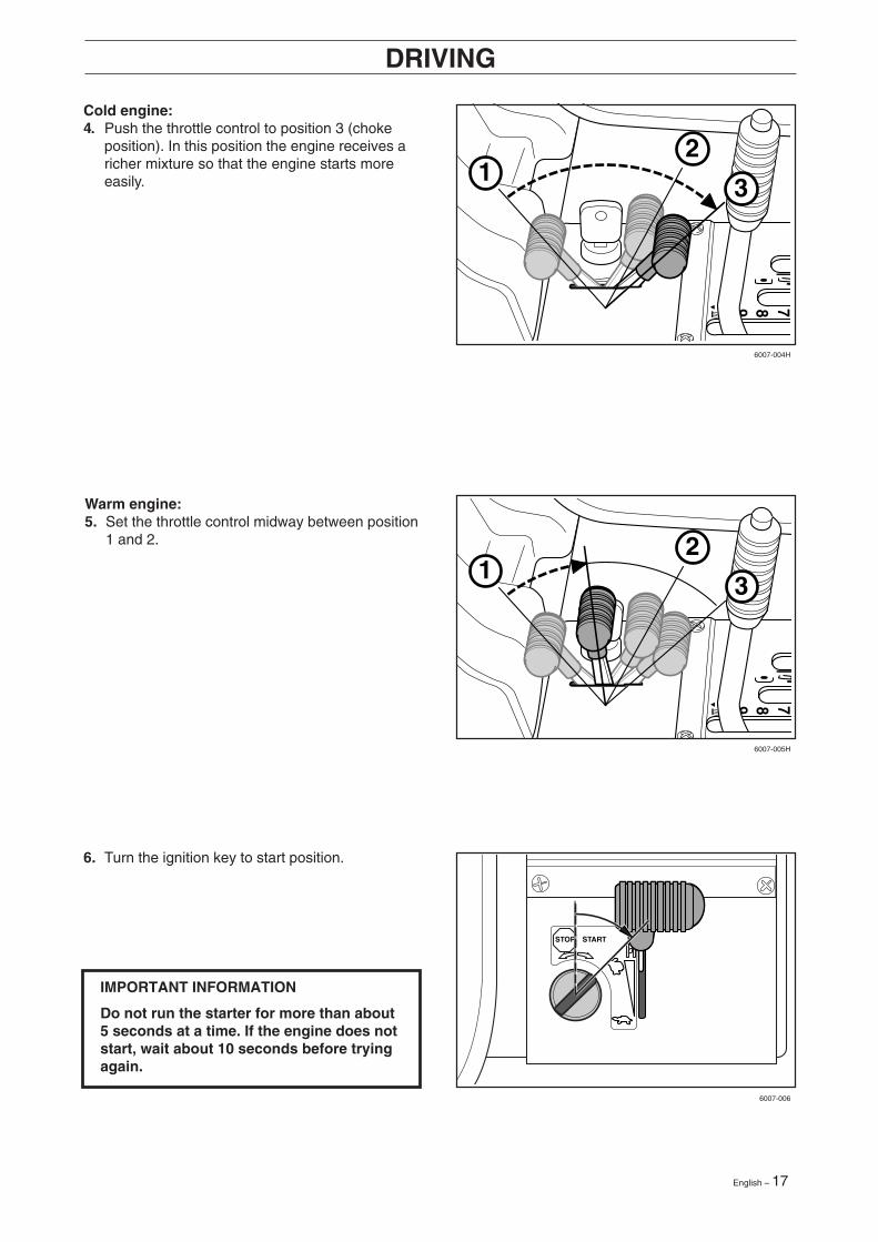
Cold engine:4. Push the throttle control to position 3 (choke
position). In this position the engine receives aricher mixture so that the engine starts moreeasily.
IMPORTANT INFORMATION
Do not run the starter for more than about5 seconds at a time. If the engine does notstart, wait about 10 seconds before tryingagain.
6. Turn the ignition key to start position.
Warm engine:5. Set the throttle control midway between position
1 and 2.
18 – English
2 1
STOP START
Rider 13
Rider 11
N
Rider 13
6007-007
6007-010H
6007-017Hy
6007-003
DRIVING
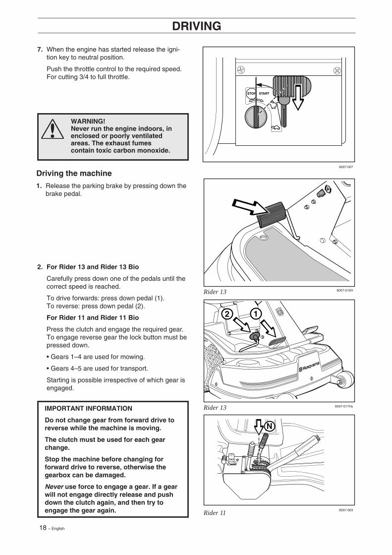
WARNING!Never run the engine indoors, inenclosed or poorly ventilatedareas. The exhaust fumescontain toxic carbon monoxide.
7. When the engine has started release the igni-tion key to neutral position.
Push the throttle control to the required speed.For cutting 3/4 to full throttle.
IMPORTANT INFORMATION
Do not change gear from forward drive toreverse while the machine is moving.
The clutch must be used for each gearchange.
Stop the machine before changing forforward drive to reverse, otherwise thegearbox can be damaged.
Never use force to engage a gear. If a gearwill not engage directly release and pushdown the clutch again, and then try toengage the gear again.
Driving the machine
1. Release the parking brake by pressing down thebrake pedal.
2. For Rider 13 and Rider 13 Bio
Carefully press down one of the pedals until thecorrect speed is reached.
To drive forwards: press down pedal (1).To reverse: press down pedal (2).
For Rider 11 and Rider 11 Bio
Press the clutch and engage the required gear.To engage reverse gear the lock button must bepressed down.
• Gears 1–4 are used for mowing.
• Gears 4–5 are used for transport.
Starting is possible irrespective of which gear isengaged.
English – 19
6007-008H
6007-009H
6007-012
IMPORTANT INFORMATION
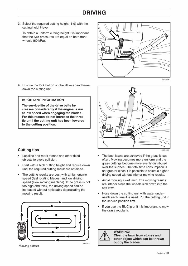
The service-life of the drive belts in-creases considerably if the engine is runat low speed when engaging the blades.For this reason do not increase the throt-tle until the cutting unit has been loweredto the cutting position.
Mowing pattern
WARNING!Clear the lawn from stones andother object which can be thrownout by the blades.
DRIVING
3. Select the required cutting height (1-9) with thecutting height lever.
To obtain a uniform cutting height it is importantthat the tyre pressures are equal on both frontwheels (60 kPa).
Cutting tips
• Localise and mark stones and other fixedobjects to avoid collision.
• Start with a high cutting height and reduce downuntil the required cutting result are obtained.
• The cutting results are best with a high enginespeed (fast rotating blades) and low drivingspeed (slow moving machine). If the grass is nottoo high and thick, the driving speed can beincreased without noticeably depreciating themowing result.
• The best lawns are achieved if the grass is cutoften. Mowing becomes more uniform and thegrass cuttings become more evenly distributedover the surface. The total time consumption isnot greater since it is possible to select a higherdriving speed without inferior mowing results.
• Avoid mowing a wet lawn. The mowing resultsare inferior since the wheels sink down into thesoft lawn.
• Hose down the cutting unit with water under-neath each time it is used. Put the cutting unit inthe service position first.
• If you use the BioClip unit it is important to mowthe grass regularly.
4. Push in the lock button on the lift lever and lowerdown the cutting unit.
20 – English
MAX 15°
STOP START
6007-013
6007-014H
6007-015
6007-217H
DRIVING
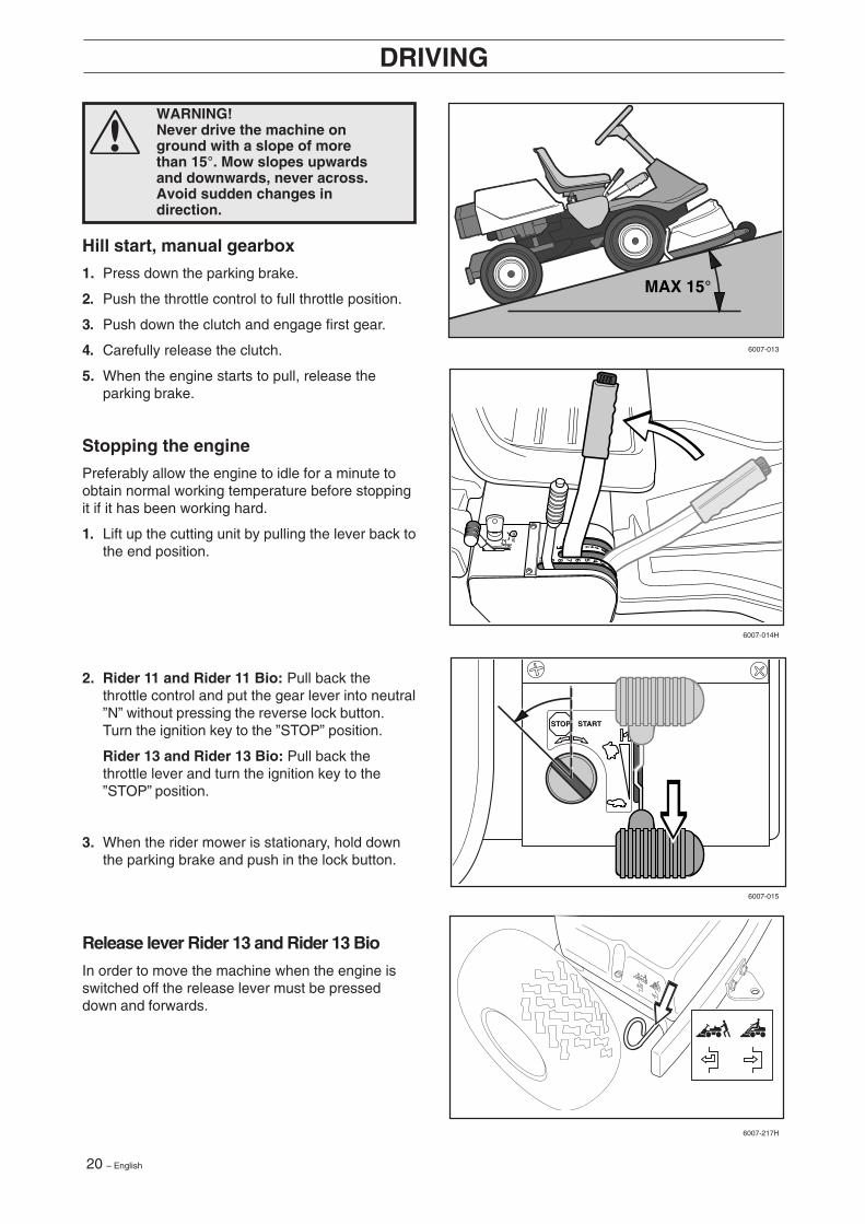
WARNING!Never drive the machine onground with a slope of morethan 15°. Mow slopes upwardsand downwards, never across.Avoid sudden changes indirection.
Release lever Rider 13 and Rider 13 Bio
In order to move the machine when the engine isswitched off the release lever must be presseddown and forwards.
Hill start, manual gearbox
1. Press down the parking brake.
2. Push the throttle control to full throttle position.
3. Push down the clutch and engage first gear.
4. Carefully release the clutch.
5. When the engine starts to pull, release theparking brake.
Stopping the engine
Preferably allow the engine to idle for a minute toobtain normal working temperature before stoppingit if it has been working hard.
1. Lift up the cutting unit by pulling the lever back tothe end position.
2. Rider 11 and Rider 11 Bio: Pull back thethrottle control and put the gear lever into neutral”N” without pressing the reverse lock button.Turn the ignition key to the ”STOP” position.
Rider 13 and Rider 13 Bio: Pull back thethrottle lever and turn the ignition key to the”STOP” position.
3. When the rider mower is stationary, hold downthe parking brake and push in the lock button.
English – 21
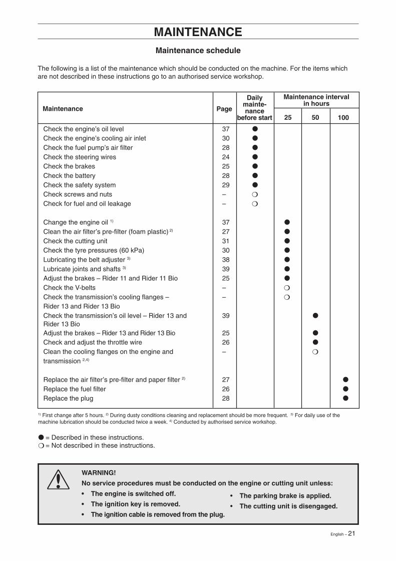
WARNING!
No service procedures must be conducted on the engine or cutting unit unless:
• The engine is switched off.
• The ignition key is removed.
• The ignition cable is removed from the plug.
• The parking brake is applied.
• The cutting unit is disengaged.
Maintenance5025 100
MAINTENANCE
Page
Maintenance intervalin hours
Dailymainte-nance
before start
Maintenance schedule
The following is a list of the maintenance which should be conducted on the machine. For the items whichare not described in these instructions go to an authorised service workshop.
● = Described in these instructions.❍ = Not described in these instructions.
1) First change after 5 hours. 2) During dusty conditions cleaning and replacement should be more frequent. 3) For daily use of themachine lubrication should be conducted twice a week. 4) Conducted by authorised service workshop.
Check the engine’s oil level 37 ●
Check the engine’s cooling air inlet 30 ●
Check the fuel pump’s air filter 28 ●
Check the steering wires 24 ●
Check the brakes 25 ●
Check the battery 28 ●
Check the safety system 29 ●
Check screws and nuts – ❍
Check for fuel and oil leakage – ❍
Change the engine oil 1) 37 ●
Clean the air filter’s pre-filter (foam plastic) 2) 27 ●
Check the cutting unit 31 ●
Check the tyre pressures (60 kPa) 30 ●
Lubricating the belt adjuster 3) 38 ●
Lubricate joints and shafts 3) 39 ●
Adjust the brakes – Rider 11 and Rider 11 Bio 25 ●
Check the V-belts – ❍
Check the transmission’s cooling flanges – – ❍
Rider 13 and Rider 13 BioCheck the transmission’s oil level – Rider 13 and 39 ●
Rider 13 BioAdjust the brakes – Rider 13 and Rider 13 Bio 25 ●
Check and adjust the throttle wire 26 ●
Clean the cooling flanges on the engine and – ❍
transmission 2,4)
Replace the air filter’s pre-filter and paper filter 2) 27 ●
Replace the fuel filter 26 ●
Replace the plug 28 ●
22 – English
6008-001
6008-002Hy
6017-215
MAINTENANCE
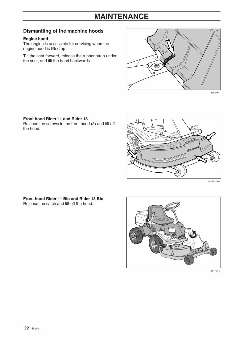
Dismantling of the machine hoods
Engine hoodThe engine is accessible for servicing when theengine hood is lifted up.
Tilt the seat forward, release the rubber strap underthe seat, and tilt the hood backwards.
Front hood Rider 11 and Rider 13Release the screws in the front hood (3) and lift offthe hood.
Front hood Rider 11 Bio and Rider 13 BioRelease the catch and lift off the hood.
English – 23
211
3
1
6008-003H
6008-004H
MAINTENANCE
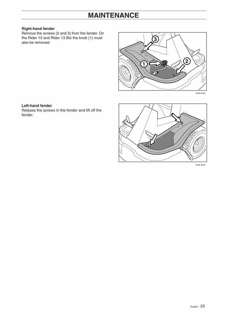
Left-hand fenderRelease the screws in the fender and lift off thefender.
Right-hand fenderRemove the screws (2 and 3) from the fender. Onthe Rider 13 and Rider 13 Bio the knob (1) mustalso be removed.
24 – English
R I D E R 8 5 0
R I D E R 8 5 0
6008-008
6008-009
608-010
MAINTENANCE
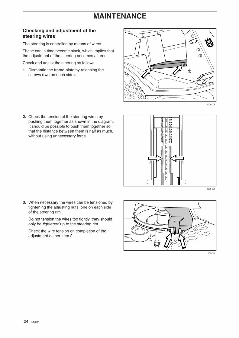
3. When necessary the wires can be tensioned bytightening the adjusting nuts, one on each sideof the steering rim.
Do not tension the wires too tightly, they shouldonly be tightened up to the steering rim.
Check the wire tension on completion of theadjustment as per item 2.
Checking and adjustment of thesteering wires
The steering is controlled by means of wires.
These can in time become slack, which implies thatthe adjustment of the steering becomes altered.
Check and adjust the steering as follows:
1. Dismantle the frame-plate by releasing thescrews (two on each side).
2. Check the tension of the steering wires bypushing them together as shown in the diagram.It should be possible to push them together sothat the distance between them is half as much,without using unnecessary force.
English – 25
21 1
1 1
2
6008-011
6008-012
6008-239H
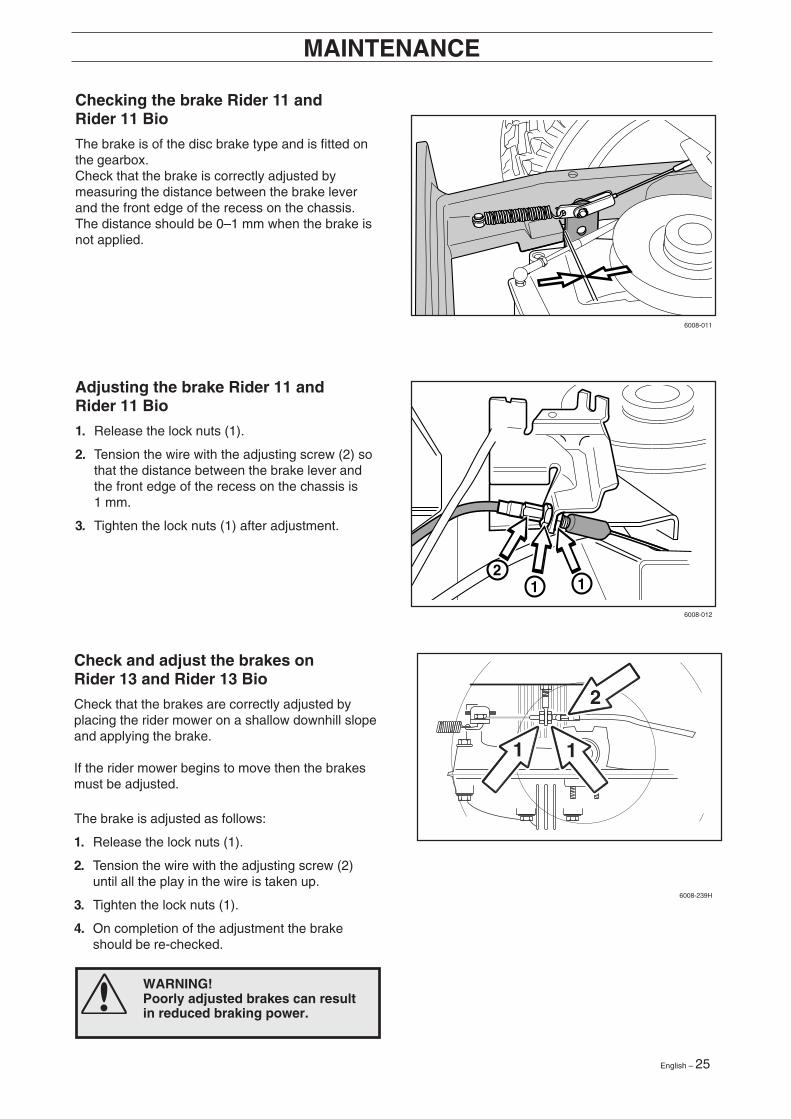
WARNING!Poorly adjusted brakes can resultin reduced braking power.
Check and adjust the brakes onRider 13 and Rider 13 Bio
Check that the brakes are correctly adjusted byplacing the rider mower on a shallow downhill slopeand applying the brake.
If the rider mower begins to move then the brakesmust be adjusted.
The brake is adjusted as follows:
1. Release the lock nuts (1).
2. Tension the wire with the adjusting screw (2)until all the play in the wire is taken up.
3. Tighten the lock nuts (1).
4. On completion of the adjustment the brakeshould be re-checked.
Checking the brake Rider 11 andRider 11 Bio
The brake is of the disc brake type and is fitted onthe gearbox.Check that the brake is correctly adjusted bymeasuring the distance between the brake leverand the front edge of the recess on the chassis.The distance should be 0–1 mm when the brake isnot applied.
Adjusting the brake Rider 11 andRider 11 Bio
1. Release the lock nuts (1).
2. Tension the wire with the adjusting screw (2) sothat the distance between the brake lever andthe front edge of the recess on the chassis is1 mm.
3. Tighten the lock nuts (1) after adjustment.
MAINTENANCE
26 – English
6008-032
6008-033
8009-108
6008-034
MAINTENANCE
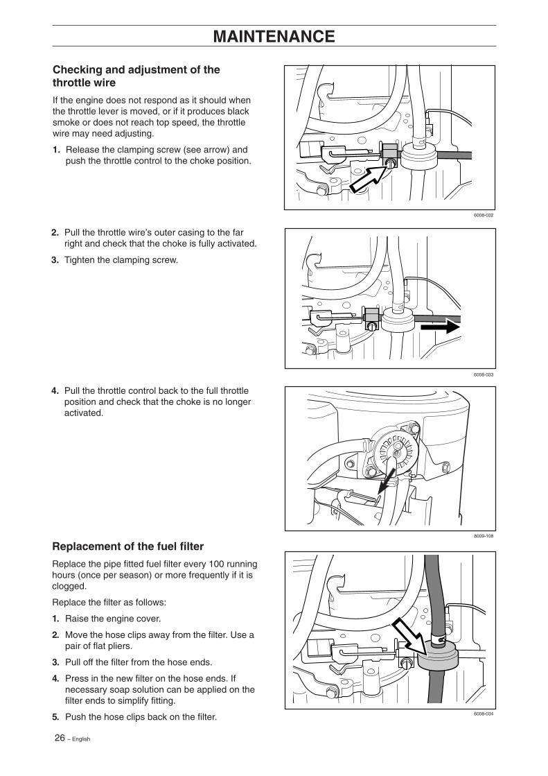
Replacement of the fuel filter
Replace the pipe fitted fuel filter every 100 runninghours (once per season) or more frequently if it isclogged.
Replace the filter as follows:
1. Raise the engine cover.
2. Move the hose clips away from the filter. Use apair of flat pliers.
3. Pull off the filter from the hose ends.
4. Press in the new filter on the hose ends. Ifnecessary soap solution can be applied on thefilter ends to simplify fitting.
5. Push the hose clips back on the filter.
2. Pull the throttle wire’s outer casing to the farright and check that the choke is fully activated.
3. Tighten the clamping screw.
Checking and adjustment of thethrottle wire
If the engine does not respond as it should whenthe throttle lever is moved, or if it produces blacksmoke or does not reach top speed, the throttlewire may need adjusting.
1. Release the clamping screw (see arrow) andpush the throttle control to the choke position.
4. Pull the throttle control back to the full throttleposition and check that the choke is no longeractivated.

English – 27
6008-014
6008-015
6008-016
6008-017
MAINTENANCE
5. Fit the air filter as follows:
Push the pre-filter over the paper filter.
Fit the paper filter with pre-filter in the air filterhousing and tighten the wing-nut.
Replace the plastic cover oven the air filterhousing and tighten the wing-nut.
Replacing the air filter
If the engine seems to lack power or goes irregu-larly the reason may be that the air filter is clogged.
It is therefore important to replace the air filter atregular intervals (see ”Maintenance \ MaintenanceSchedule” for correct service interval)
The air filter is replaced as follows:
1. Raise the engine cover.
2. Remove the air filter housing’s plastic cover byreleasing the wing-nut.
4. Pull off the foam plastic pre-filter from the paperfilter and wash clean in mild detergent.
Squeeze it dry in a clean cloth.
Drench it with new engine oil. Wrap the filter inan absorbent cloth and squeeze out excess oil.
Replace the paper filter if it is clogged with dirt.
IMPORTANT INFORMATION
Do not use compressed air to clean thepaper filter.
3. Remove the wing-nut on the air filter and lift offthe paper filter with pre-filter.
28 – English
8009-108
6008-013
MAINTENANCE
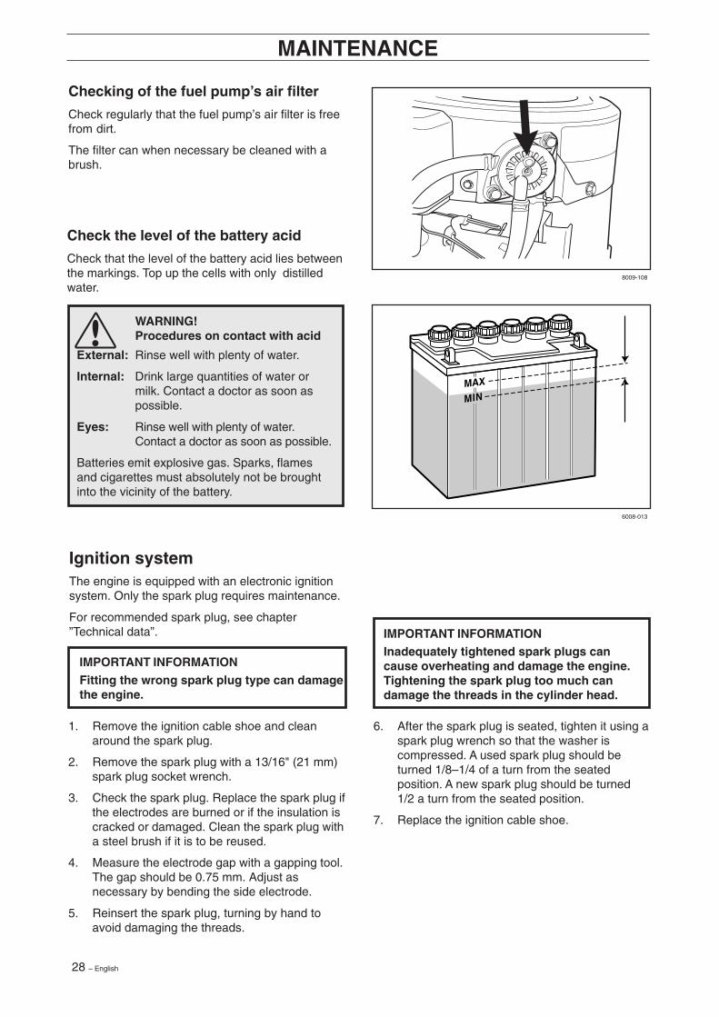
Checking of the fuel pump’s air filter
Check regularly that the fuel pump’s air filter is freefrom dirt.
The filter can when necessary be cleaned with abrush.
WARNING!Procedures on contact with acid
External: Rinse well with plenty of water.
Internal: Drink large quantities of water ormilk. Contact a doctor as soon aspossible.
Eyes: Rinse well with plenty of water.Contact a doctor as soon as possible.
Batteries emit explosive gas. Sparks, flamesand cigarettes must absolutely not be broughtinto the vicinity of the battery.
Check the level of the battery acid
Check that the level of the battery acid lies betweenthe markings. Top up the cells with only distilledwater.
Ignition systemThe engine is equipped with an electronic ignitionsystem. Only the spark plug requires maintenance.
For recommended spark plug, see chapter”Technical data”.
IMPORTANT INFORMATION
Fitting the wrong spark plug type can damagethe engine.
1. Remove the ignition cable shoe and cleanaround the spark plug.
2. Remove the spark plug with a 13/16" (21 mm)spark plug socket wrench.
3. Check the spark plug. Replace the spark plug ifthe electrodes are burned or if the insulation iscracked or damaged. Clean the spark plug witha steel brush if it is to be reused.
4. Measure the electrode gap with a gapping tool.The gap should be 0.75 mm. Adjust asnecessary by bending the side electrode.
5. Reinsert the spark plug, turning by hand toavoid damaging the threads.
IMPORTANT INFORMATIONInadequately tightened spark plugs cancause overheating and damage the engine.Tightening the spark plug too much candamage the threads in the cylinder head.
6. After the spark plug is seated, tighten it using aspark plug wrench so that the washer iscompressed. A used spark plug should beturned 1/8–1/4 of a turn from the seatedposition. A new spark plug should be turned1/2 a turn from the seated position.
7. Replace the ignition cable shoe.
English – 29
N
Rider 13
Rider 11
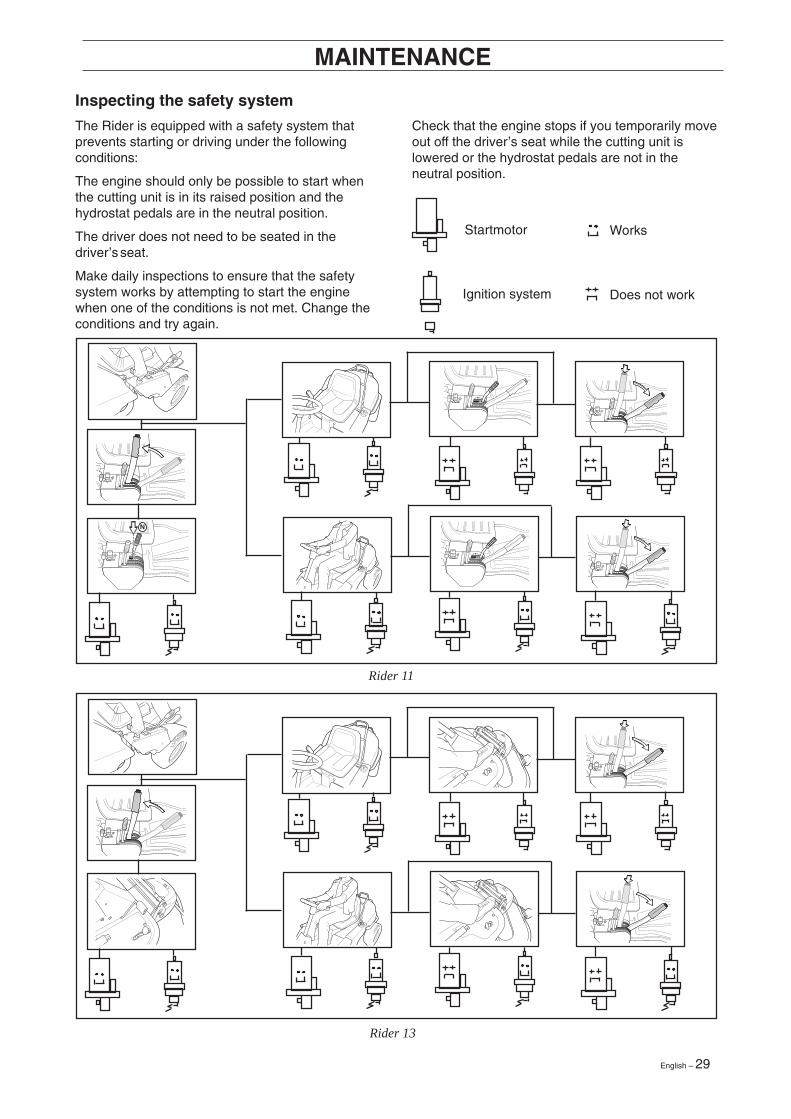
Inspecting the safety system
The Rider is equipped with a safety system thatprevents starting or driving under the followingconditions:
The engine should only be possible to start whenthe cutting unit is in its raised position and thehydrostat pedals are in the neutral position.
The driver does not need to be seated in thedriver’s seat.
Make daily inspections to ensure that the safetysystem works by attempting to start the enginewhen one of the conditions is not met. Change theconditions and try again.
Check that the engine stops if you temporarily moveout off the driver’s seat while the cutting unit islowered or the hydrostat pedals are not in theneutral position.
Startmotor
Ignition system
Works
Does not work
MAINTENANCE
30 – English
R I D E R 8 5 0
R I D E R 8 5 0
6008-030
6008-006
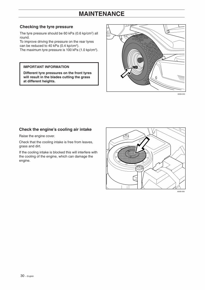
Checking the tyre pressure
The tyre pressure should be 60 kPa (0.6 kp/cm2) allround.To improve driving the pressure on the rear tyrescan be reduced to 40 kPa (0.4 kp/cm2).The maximum tyre pressure is 100 kPa (1.0 kp/cm2).
IMPORTANT INFORMATION
Different tyre pressures on the front tyreswill result in the blades cutting the grassat different heights.
MAINTENANCE
Check the engine’s cooling air intake
Raise the engine cover.
Check that the cooling intake is free from leaves,grass and dirt.
If the cooling intake is blocked this will interfere withthe cooling of the engine, which can damage theengine.
English – 31
6017-216
6008-019
6017-217
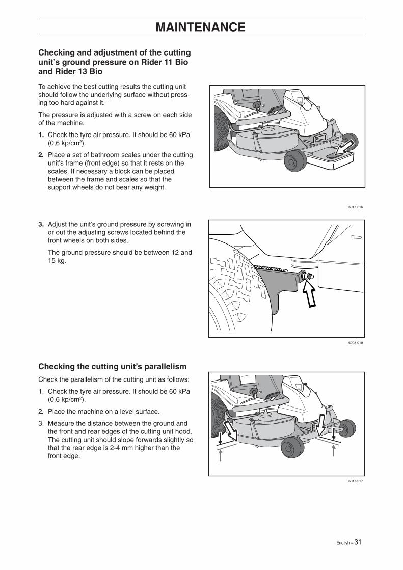
Checking and adjustment of the cuttingunit’s ground pressure on Rider 11 Bioand Rider 13 Bio
Checking the cutting unit’s parallelism
Check the parallelism of the cutting unit as follows:
1. Check the tyre air pressure. It should be 60 kPa(0,6 kp/cm2).
2. Place the machine on a level surface.
3. Measure the distance between the ground andthe front and rear edges of the cutting unit hood.The cutting unit should slope forwards slightly sothat the rear edge is 2-4 mm higher than thefront edge.
MAINTENANCE
To achieve the best cutting results the cutting unitshould follow the underlying surface without press-ing too hard against it.
The pressure is adjusted with a screw on each sideof the machine.
1. Check the tyre air pressure. It should be 60 kPa(0,6 kp/cm2).
2. Place a set of bathroom scales under the cuttingunit’s frame (front edge) so that it rests on thescales. If necessary a block can be placedbetween the frame and scales so that thesupport wheels do not bear any weight.
3. Adjust the unit’s ground pressure by screwing inor out the adjusting screws located behind thefront wheels on both sides.
The ground pressure should be between 12 and15 kg.
32 – English
2
6008-026H
8009-138
MAINTENANCE
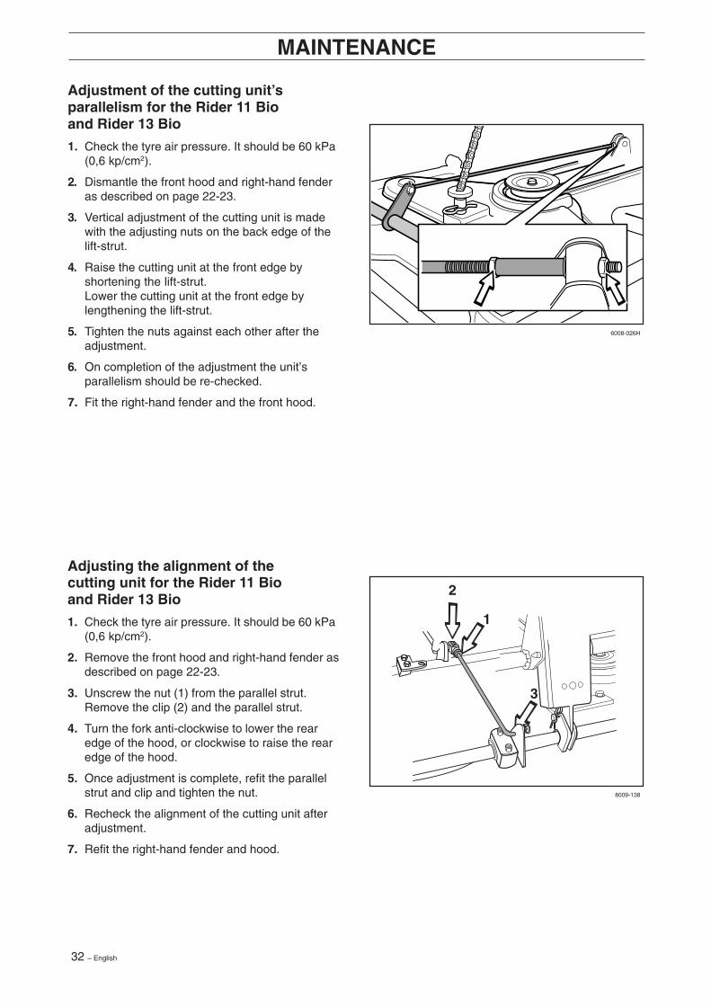
Adjustment of the cutting unit’sparallelism for the Rider 11 Bioand Rider 13 Bio
1. Check the tyre air pressure. It should be 60 kPa(0,6 kp/cm2).
2. Dismantle the front hood and right-hand fenderas described on page 22-23.
3. Vertical adjustment of the cutting unit is madewith the adjusting nuts on the back edge of thelift-strut.
4. Raise the cutting unit at the front edge byshortening the lift-strut.Lower the cutting unit at the front edge bylengthening the lift-strut.
5. Tighten the nuts against each other after theadjustment.
6. On completion of the adjustment the unit’sparallelism should be re-checked.
7. Fit the right-hand fender and the front hood.
Adjusting the alignment of thecutting unit for the Rider 11 Bioand Rider 13 Bio
1. Check the tyre air pressure. It should be 60 kPa(0,6 kp/cm2).
2. Remove the front hood and right-hand fender asdescribed on page 22-23.
3. Unscrew the nut (1) from the parallel strut.Remove the clip (2) and the parallel strut.
4. Turn the fork anti-clockwise to lower the rearedge of the hood, or clockwise to raise the rearedge of the hood.
5. Once adjustment is complete, refit the parallelstrut and clip and tighten the nut.
6. Recheck the alignment of the cutting unit afteradjustment.
7. Refit the right-hand fender and hood.
English – 33
P1
6017-218
6017-219
6017-220
MAINTENANCE RIDER 11 BIO/13 BIO
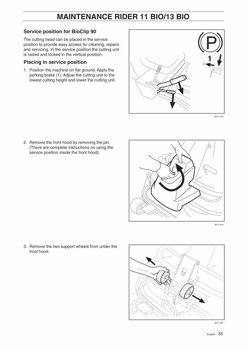
Service position for BioClip 90
The cutting head can be placed in the serviceposition to provide easy access for cleaning, repairsand servicing. In the service position the cutting unitis raised and locked in the vertical position.
Placing in service position
1. Position the machine on flat ground. Apply theparking brake (1). Adjust the cutting unit to thelowest cutting height and lower the cutting unit.
3. Remove the two support wheels from under thefront hood.
2. Remove the front hood by removing the pin.(There are complete instructions on using theservice position inside the front hood).
34 – English
6017-221
6017-222
8009-122
6017-223
MAINTENANCE RIDER 11 BIO/13 BIO
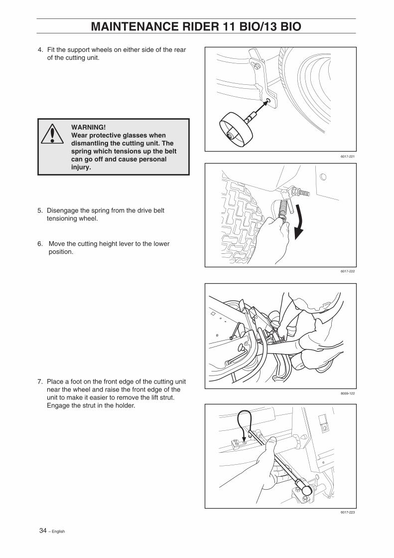
4. Fit the support wheels on either side of the rearof the cutting unit.
5. Disengage the spring from the drive belttensioning wheel.
6. Move the cutting height lever to the lowerposition.
7. Place a foot on the front edge of the cutting unitnear the wheel and raise the front edge of theunit to make it easier to remove the lift strut.Engage the strut in the holder.
WARNING!Wear protective glasses whendismantling the cutting unit. Thespring which tensions up the beltcan go off and cause personalinjury.
English – 35
2
1
6017-225
6017-226
6017-227
8009-123
MAINTENANCE RIDER 11 BIO/13 BIO
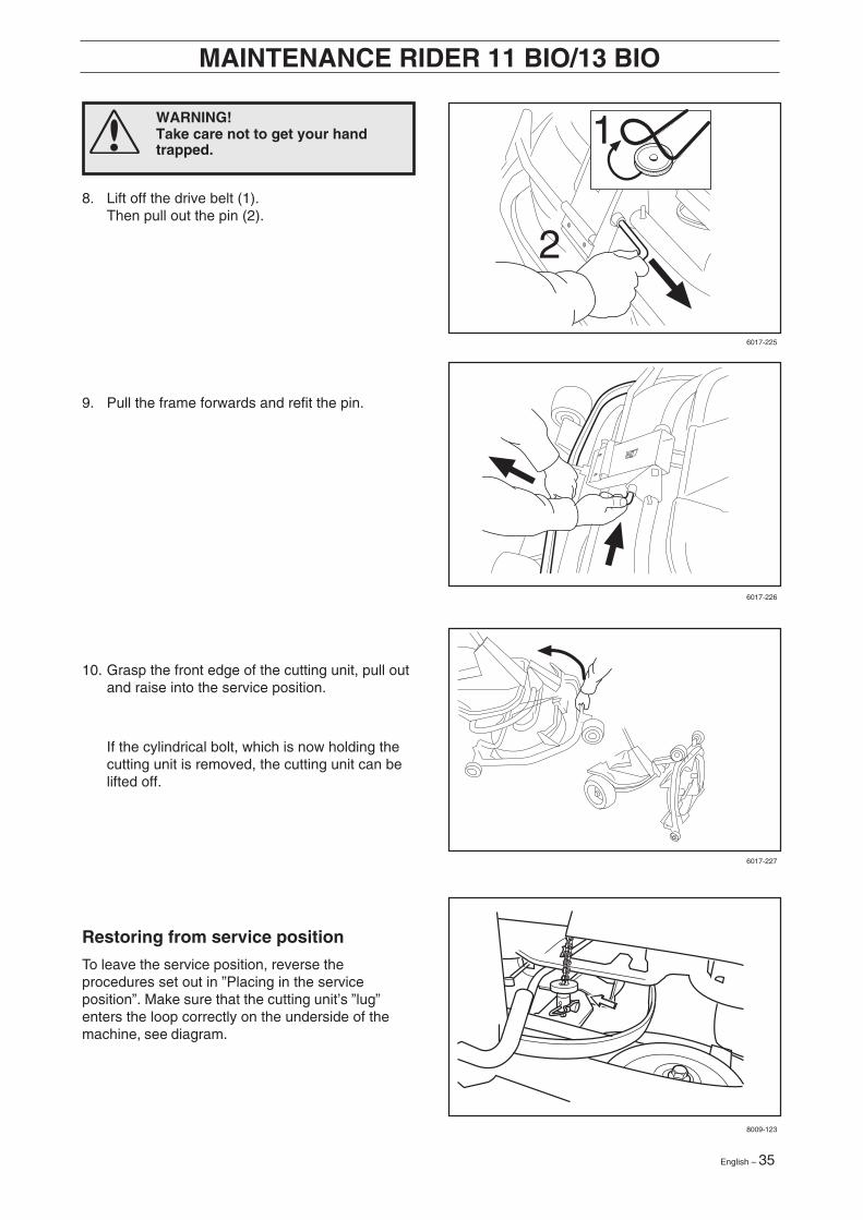
8. Lift off the drive belt (1).Then pull out the pin (2).
9. Pull the frame forwards and refit the pin.
10. Grasp the front edge of the cutting unit, pull outand raise into the service position.
If the cylindrical bolt, which is now holding thecutting unit is removed, the cutting unit can belifted off.
Restoring from service position
To leave the service position, reverse theprocedures set out in ”Placing in the serviceposition”. Make sure that the cutting unit’s ”lug”enters the loop correctly on the underside of themachine, see diagram.
WARNING!Take care not to get your handtrapped.
36 – English
2B
3
4
4
6
2A
7
8
5
Klippaggregat (bakutkast)
BioClip 90
6008-024
6017-223
8009-137
MAINTENANCE
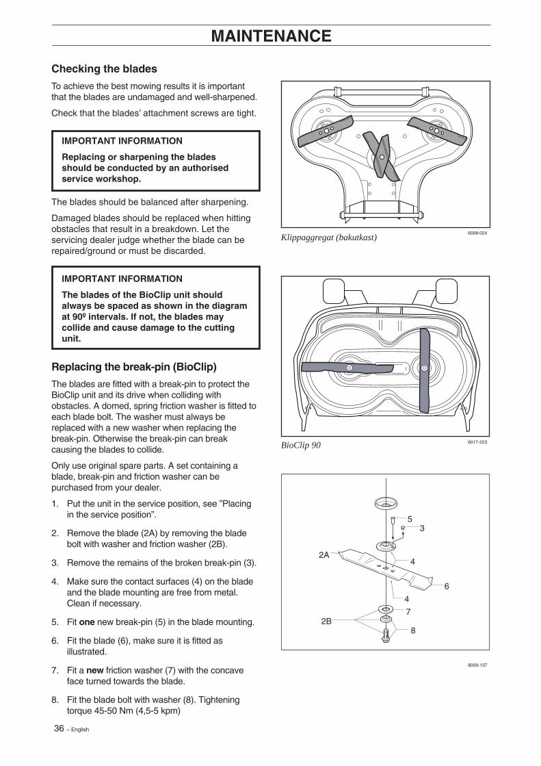
Checking the blades
To achieve the best mowing results it is importantthat the blades are undamaged and well-sharpened.
Check that the blades’ attachment screws are tight.
IMPORTANT INFORMATION
Replacing or sharpening the bladesshould be conducted by an authorisedservice workshop.
IMPORTANT INFORMATION
The blades of the BioClip unit shouldalways be spaced as shown in the diagramat 90º intervals. If not, the blades maycollide and cause damage to the cuttingunit.
The blades should be balanced after sharpening.
Damaged blades should be replaced when hittingobstacles that result in a breakdown. Let theservicing dealer judge whether the blade can berepaired/ground or must be discarded.
Replacing the break-pin (BioClip)
The blades are fitted with a break-pin to protect theBioClip unit and its drive when colliding withobstacles. A domed, spring friction washer is fitted toeach blade bolt. The washer must always bereplaced with a new washer when replacing thebreak-pin. Otherwise the break-pin can breakcausing the blades to collide.
Only use original spare parts. A set containing ablade, break-pin and friction washer can bepurchased from your dealer.
1. Put the unit in the service position, see ”Placingin the service position”.
2. Remove the blade (2A) by removing the bladebolt with washer and friction washer (2B).
3. Remove the remains of the broken break-pin (3).
4. Make sure the contact surfaces (4) on the bladeand the blade mounting are free from metal.Clean if necessary.
5. Fit one new break-pin (5) in the blade mounting.
6. Fit the blade (6), make sure it is fitted asillustrated.
7. Fit a new friction washer (7) with the concaveface turned towards the blade.
8. Fit the blade bolt with washer (8). Tighteningtorque 45-50 Nm (4,5-5 kpm)
English – 37
ADD FULL
ADD FULL
6008-005
6008-035
6008-027
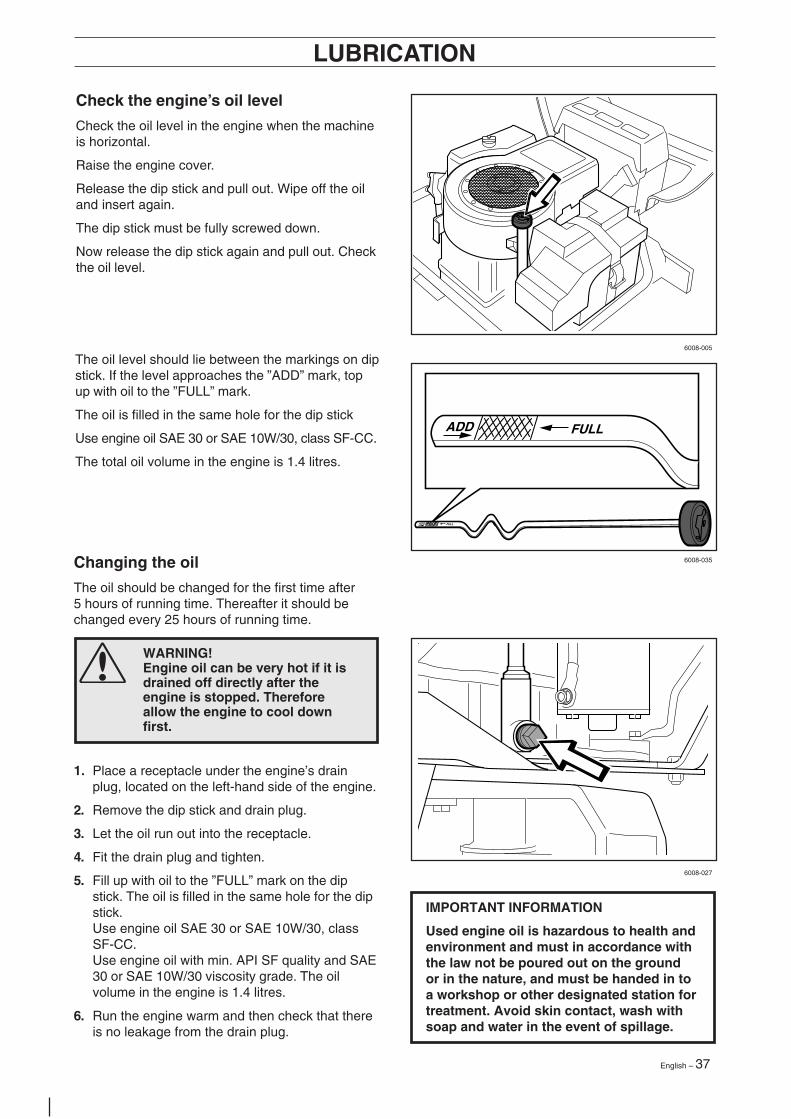
The oil level should lie between the markings on dipstick. If the level approaches the ”ADD” mark, topup with oil to the ”FULL” mark.
The oil is filled in the same hole for the dip stick
Use engine oil SAE 30 or SAE 10W/30, class SF-CC.
The total oil volume in the engine is 1.4 litres.
Check the engine’s oil level
Check the oil level in the engine when the machineis horizontal.
Raise the engine cover.
Release the dip stick and pull out. Wipe off the oiland insert again.
The dip stick must be fully screwed down.
Now release the dip stick again and pull out. Checkthe oil level.
LUBRICATION
WARNING!Engine oil can be very hot if it isdrained off directly after theengine is stopped. Thereforeallow the engine to cool downfirst.
1. Place a receptacle under the engine’s drainplug, located on the left-hand side of the engine.
2. Remove the dip stick and drain plug.
3. Let the oil run out into the receptacle.
4. Fit the drain plug and tighten.
5. Fill up with oil to the ”FULL” mark on the dipstick. The oil is filled in the same hole for the dipstick.Use engine oil SAE 30 or SAE 10W/30, classSF-CC.Use engine oil with min. API SF quality and SAE30 or SAE 10W/30 viscosity grade. The oilvolume in the engine is 1.4 litres.
6. Run the engine warm and then check that thereis no leakage from the drain plug.
Changing the oil
The oil should be changed for the first time after5 hours of running time. Thereafter it should bechanged every 25 hours of running time.
IMPORTANT INFORMATION
Used engine oil is hazardous to health andenvironment and must in accordance withthe law not be poured out on the groundor in the nature, and must be handed in toa workshop or other designated station fortreatment. Avoid skin contact, wash withsoap and water in the event of spillage.
38 – English
6008-039H
6008-240H
6008-232
LUBRICATION
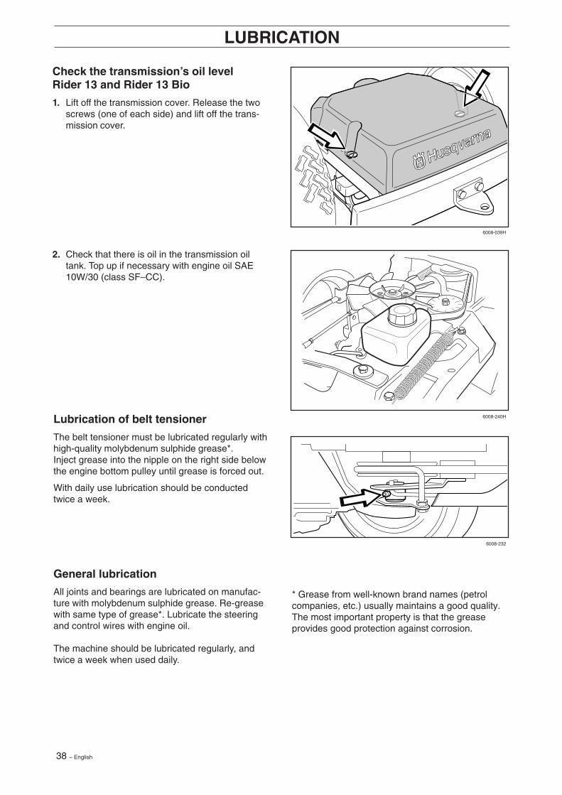
Check the transmission’s oil levelRider 13 and Rider 13 Bio
1. Lift off the transmission cover. Release the twoscrews (one of each side) and lift off the trans-mission cover.
2. Check that there is oil in the transmission oiltank. Top up if necessary with engine oil SAE10W/30 (class SF–CC).
Lubrication of belt tensioner
The belt tensioner must be lubricated regularly withhigh-quality molybdenum sulphide grease*.Inject grease into the nipple on the right side belowthe engine bottom pulley until grease is forced out.
With daily use lubrication should be conductedtwice a week.
General lubrication
All joints and bearings are lubricated on manufac-ture with molybdenum sulphide grease. Re-greasewith same type of grease*. Lubricate the steeringand control wires with engine oil.
The machine should be lubricated regularly, andtwice a week when used daily.
* Grease from well-known brand names (petrolcompanies, etc.) usually maintains a good quality.The most important property is that the greaseprovides good protection against corrosion.
English – 39
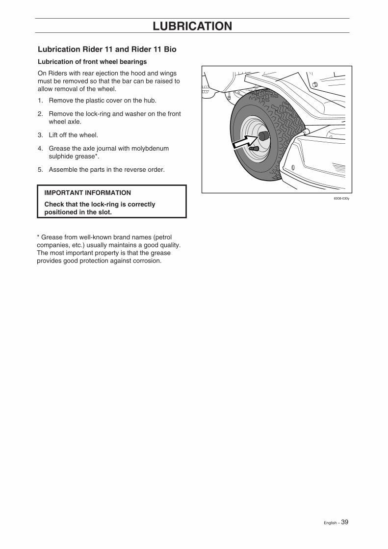
6008-030yIMPORTANT INFORMATION
Check that the lock-ring is correctlypositioned in the slot.
Lubrication Rider 11 and Rider 11 Bio
Lubrication of front wheel bearings
On Riders with rear ejection the hood and wingsmust be removed so that the bar can be raised toallow removal of the wheel.
1. Remove the plastic cover on the hub.
2. Remove the lock-ring and washer on the frontwheel axle.
3. Lift off the wheel.
4. Grease the axle journal with molybdenumsulphide grease*.
5. Assemble the parts in the reverse order.
LUBRICATION
* Grease from well-known brand names (petrolcompanies, etc.) usually maintains a good quality.The most important property is that the greaseprovides good protection against corrosion.

40 – English
Problem Procedure
Engine will not start • Fuel tank empty• Plug defective• Plug connection defective• Dirt in carburettor or fuel pipe
Starter does not pull round engine • Battery flat• Bad contact between cable and battery terminal• Lift lever for cutting unit in wrong position• Main fuse blown. The fuse is placed in front of the
battery, under the battery cover.• Ignition lock faulty• Gear shift/hydrostat pedal not in neutral
Engine does not run smoothly • Wrong gear, too high• Carburettor incorrectly set• Air filter clogged• Fuel tank vent blocked• Ignition setting defective• Dirt in fuel pipe• Choke activated or throttle wire incorrectly adjusted
Engine seems to have no power • Air filter clogged• Plug defective• Dirt in carburettor or fuel pipe• Carburettor incorrectly set• Choke activated or throttle wire incorrectly adjusted
Engine overheats • Engine overloaded• Air intake or cooling flanges blocked• Fan damaged• Too little or no oil in engine• Ignition defective• Plug defective
Battery does not charge • One or more cells faulty• Bad contact between battery terminals and cables.
Machine vibrates • Blades are loose• Engine is loose• Imbalance on one or more blades, resulting from
damage or inferior balancing after sharpening
Uneven mowing • Blades blunt• Cutting unit skew• Long or wet grass• Grass blockage under hood• Different tyre pressures on right and left sides• Over-speeding• Drive belts slipping• The blade has a broken break-pin (BioClip)
TROUBLE SHOOTING SCHEDULE
English – 41
6004-001Hy
6017-213
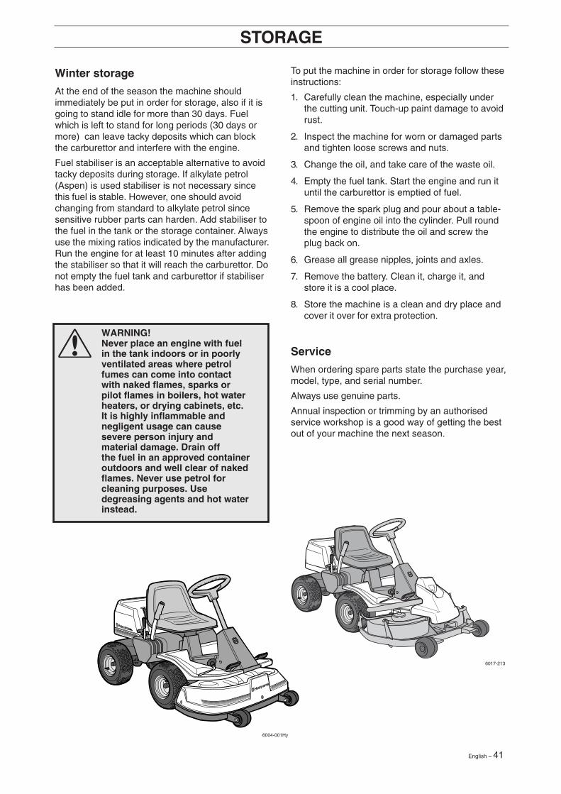
To put the machine in order for storage follow theseinstructions:
1. Carefully clean the machine, especially underthe cutting unit. Touch-up paint damage to avoidrust.
2. Inspect the machine for worn or damaged partsand tighten loose screws and nuts.
3. Change the oil, and take care of the waste oil.
4. Empty the fuel tank. Start the engine and run ituntil the carburettor is emptied of fuel.
5. Remove the spark plug and pour about a table-spoon of engine oil into the cylinder. Pull roundthe engine to distribute the oil and screw theplug back on.
6. Grease all grease nipples, joints and axles.
7. Remove the battery. Clean it, charge it, andstore it is a cool place.
8. Store the machine is a clean and dry place andcover it over for extra protection.
Service
When ordering spare parts state the purchase year,model, type, and serial number.
Always use genuine parts.
Annual inspection or trimming by an authorisedservice workshop is a good way of getting the bestout of your machine the next season.
Winter storage
At the end of the season the machine shouldimmediately be put in order for storage, also if it isgoing to stand idle for more than 30 days. Fuelwhich is left to stand for long periods (30 days ormore) can leave tacky deposits which can blockthe carburettor and interfere with the engine.
Fuel stabiliser is an acceptable alternative to avoidtacky deposits during storage. If alkylate petrol(Aspen) is used stabiliser is not necessary sincethis fuel is stable. However, one should avoidchanging from standard to alkylate petrol sincesensitive rubber parts can harden. Add stabiliser tothe fuel in the tank or the storage container. Alwaysuse the mixing ratios indicated by the manufacturer.Run the engine for at least 10 minutes after addingthe stabiliser so that it will reach the carburettor. Donot empty the fuel tank and carburettor if stabiliserhas been added.
STORAGE
WARNING!Never place an engine with fuelin the tank indoors or in poorlyventilated areas where petrolfumes can come into contactwith naked flames, sparks orpilot flames in boilers, hot waterheaters, or drying cabinets, etc.It is highly inflammable andnegligent usage can causesevere person injury andmaterial damage. Drain offthe fuel in an approved containeroutdoors and well clear of nakedflames. Never use petrol forcleaning purposes. Usedegreasing agents and hot waterinstead.
42 – English
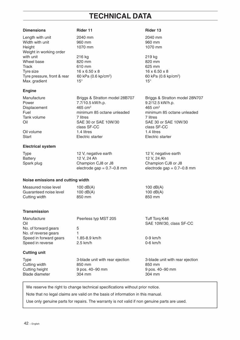
Dimensions Rider 11 Rider 13
Length with unit 2040 mm 2040 mmWidth with unit 960 mm 960 mmHeight 1070 mm 1070 mmWeight in working orderwith unit 216 kg 219 kgWheel base 820 mm 820 mmTrack 610 mm 625 mmTyre size 16 x 6.50 x 8 16 x 6.50 x 8Tyre pressure, front & rear 60 kPa (0.6 kp/cm2) 60 kPa (0.6 kp/cm2)Max. gradient 15° 15°
Engine
Manufacture Briggs & Stratton model 28B707 Briggs & Stratton model 28N707Power 7.7/10.5 kW/h.p. 9.2/12.5 kW/h.p.Displacement 465 cm3 465 cm3
Fuel minimum 85 octane unleaded minimum 85 octane unleadedTank volume 7 litres 7 litresOil SAE 30 or SAE 10W/30 SAE 30 or SAE 10W/30
class SF-CC class SF-CCOil volume 1.4 litres 1.4 litresStart Electric starter Electric starter
Electrical system
Type 12 V, negative earth 12 V, negative earthBattery 12 V, 24 Ah 12 V, 24 AhSpark plug Champion CJ8 or J8 Champion CJ8 or J8
electrode gap = 0.7–0.8 mm electrode gap = 0.7–0.8 mm
Noise emissions and cutting width
Measured noise level 100 dB(A) 100 dB(A)Guaranteed noise level 100 dB(A) 100 dB(A)Cutting width 850 mm 850 mm
Transmission
Manufacture Peerless typ MST 205 Tuff Torq K46Oil SAE 10W/30, class SF-CCNo. of forward gears 5No. of reverse gears 1Speed in forward gears 1.85-8.9 km/h 0-9 km/hSpeed in reverse 2.5 km/h 0-6 km/h
Cutting unit
Type 3-blade unit with rear ejection 3-blade unit with rear ejectionCutting width 850 mm 850 mmCutting height 9 pos. 40–90 mm 9 pos. 40–90 mmBlade diameter 304 mm 304 mm
TECHNICAL DATA
We reserve the right to change technical specifications without prior notice.
Note that no legal claims are valid on the basis of information in this manual.
Use only genuine parts for repairs. The warranty is not valid if non genuine parts are used.
English – 43
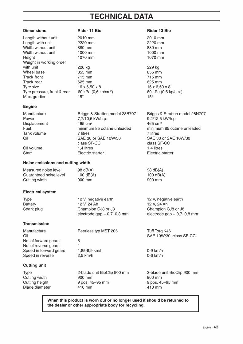
Dimensions Rider 11 Bio Rider 13 Bio
Length without unit 2010 mm 2010 mmLength with unit 2220 mm 2220 mmWidth without unit 880 mm 880 mmWidth without unit 1000 mm 1000 mmHeight 1070 mm 1070 mmWeight in working orderwith unit 226 kg 229 kgWheel base 855 mm 855 mmTrack front 715 mm 715 mmTrack rear 625 mm 625 mmTyre size 16 x 6,50 x 8 16 x 6,50 x 8Tyre pressure, front & rear 60 kPa (0,6 kp/cm2) 60 kPa (0,6 kp/cm2)Max. gradient 15° 15°
Engine
Manufacture Briggs & Stratton model 28B707 Briggs & Stratton model 28N707Power 7,7/10,5 kW/h.p. 9,2/12,5 kW/h.p.Displacement 465 cm3 465 cm3
Fuel minimum 85 octane unleaded minimum 85 octane unleadedTank volume 7 litres 7 litresOil SAE 30 or SAE 10W/30 SAE 30 or SAE 10W/30
class SF-CC class SF-CCOil volume 1,4 litres 1,4 litresStart Electric starter Electric starter
Noise emissions and cutting width
Measured noise level 98 dB(A) 98 dB(A)Guaranteed noise level 100 dB(A) 100 dB(A)Cutting width 900 mm 900 mm
Electrical system
Type 12 V, negative earth 12 V, negative earthBattery 12 V, 24 Ah 12 V, 24 AhSpark plug Champion CJ8 or J8 Champion CJ8 or J8
electrode gap = 0,7–0,8 mm electrode gap = 0,7–0,8 mm
Transmission
Manufacture Peerless typ MST 205 Tuff Torq K46Oil SAE 10W/30, class SF-CCNo. of forward gears 5No. of reverse gears 1Speed in forward gears 1,85-8,9 km/h 0-9 km/hSpeed in reverse 2,5 km/h 0-6 km/h
Cutting unit
Type 2-blade unit BioClip 900 mm 2-blade unit BioClip 900 mmCutting width 900 mm 900 mmCutting height 9 pos. 45–95 mm 9 pos. 45–95 mmBlade diameter 410 mm 410 mm
TECHNICAL DATA
When this product is worn out or no longer used it should be returned tothe dealer or other appropriate body for recycling.

44 – English
EU declaration of conformity (Only applies to Europe)
Husqvarna AB, SE-561 82 Huskvarna, Sweden, tel: +46-36-146500, declares under sole responsibility thatHusqvarna Rider 11/11 Bio and Rider 13/13 Bio, from 2002’s serial numbers and onwards (the year is clearlystated in plain text on the rating plate with subsequent serial number), complies with the requirements of theCOUNCIL’S DIRECTIVES:
- of June 22, 1998 ”relating to machinery” 98/37/EC, annex IIA.- of May 3, 1989 ”relating to electromagnetic compatibility” 89/336/EEC, and applicable supplements.- of May 8, 2000 ”relating to the emission of noise to surroundings” 2000/14/EC.Information regarding noise emissions and the mowing width, see the Technical Data.
The following harmonised standards have been applied: EN292-2, EN836.
The registered body 0404, SMP Svensk Maskinprovning AB, Fyrisborgsgatan 3, SE-754 50 Uppsala, Sweden hasissued the report with number 01/901/001, 01/901/002, 01/901/003, 01/901/004 regarding the assessment ofconformity according to annex VI to the COUNCIL’S DIRECTIVE of May 8, 2000 ”relating to the emission of noise tosurroundings” 2000/14/EC.
Huskvarna January 3, 2002
Roger Andersson, Development Manager/Garden Products
EU-DECLARATION OF CONFORMITY
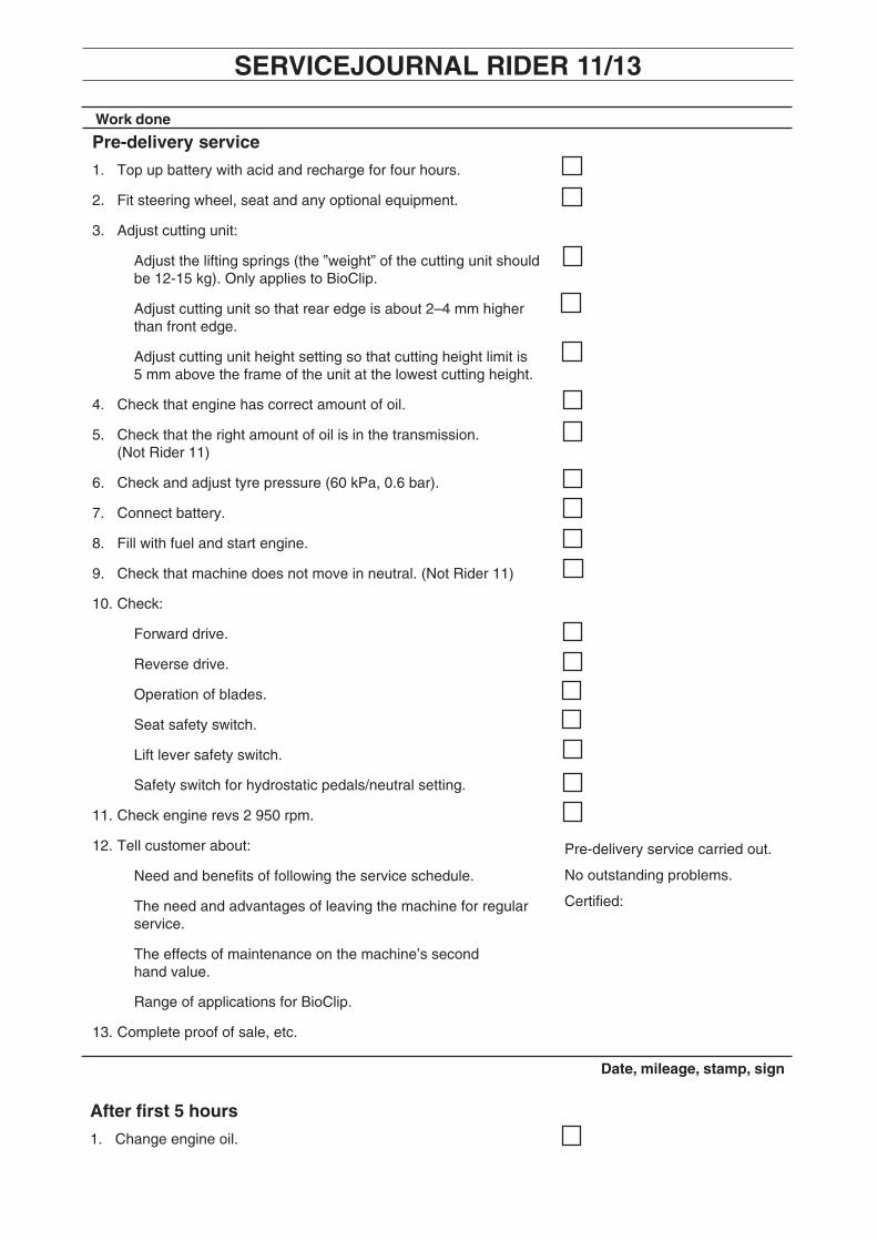
Pre-delivery service
1. Top up battery with acid and recharge for four hours.
2. Fit steering wheel, seat and any optional equipment.
3. Adjust cutting unit:
Adjust the lifting springs (the ”weight” of the cutting unit shouldbe 12-15 kg). Only applies to BioClip.
Adjust cutting unit so that rear edge is about 2–4 mm higherthan front edge.
Adjust cutting unit height setting so that cutting height limit is5 mm above the frame of the unit at the lowest cutting height.
4. Check that engine has correct amount of oil.
5. Check that the right amount of oil is in the transmission.(Not Rider 11)
6. Check and adjust tyre pressure (60 kPa, 0.6 bar).
7. Connect battery.
8. Fill with fuel and start engine.
9. Check that machine does not move in neutral. (Not Rider 11)
10. Check:
Forward drive.
Reverse drive.
Operation of blades.
Seat safety switch.
Lift lever safety switch.
Safety switch for hydrostatic pedals/neutral setting.
11. Check engine revs 2 950 rpm.
12. Tell customer about:
Need and benefits of following the service schedule.
The need and advantages of leaving the machine for regularservice.
The effects of maintenance on the machine’s secondhand value.
Range of applications for BioClip.
13. Complete proof of sale, etc.
Pre-delivery service carried out.
No outstanding problems.
Certified:
After first 5 hours
1. Change engine oil.
Work done
SERVICEJOURNAL RIDER 11/13
Date, mileage, stamp, sign

46 – English
○ ○ ○ ○ ○ ○ ○ ○ ○ ○ ○ ○ ○ ○ ○ ○ ○ ○ ○ ○ ○ ○ ○ ○ ○ ○ ○ ○ ○ ○ ○ ○ ○ ○ ○ ○ ○ ○ ○ ○ ○ ○ ○ ○ ○ ○ ○ ○ ○ ○ ○ ○ ○ ○ ○ ○ ○ ○ ○ ○ ○
○ ○ ○ ○ ○ ○ ○ ○ ○ ○ ○ ○ ○ ○ ○ ○ ○ ○ ○ ○ ○ ○ ○ ○ ○ ○ ○ ○ ○ ○ ○ ○ ○ ○ ○ ○ ○ ○ ○ ○ ○ ○ ○ ○ ○ ○ ○ ○ ○ ○ ○ ○ ○ ○ ○ ○ ○ ○ ○ ○ ○
○ ○ ○ ○ ○ ○ ○ ○ ○ ○ ○ ○ ○ ○ ○ ○ ○ ○ ○ ○ ○ ○ ○ ○ ○ ○ ○ ○ ○ ○ ○ ○ ○ ○ ○ ○ ○ ○ ○ ○ ○ ○ ○ ○ ○ ○ ○ ○ ○ ○ ○ ○ ○ ○ ○ ○ ○ ○ ○ ○ ○○ ○ ○ ○ ○ ○ ○ ○ ○ ○ ○ ○ ○ ○ ○ ○ ○ ○ ○ ○ ○ ○ ○ ○ ○ ○ ○ ○ ○ ○ ○ ○ ○ ○ ○ ○ ○ ○ ○ ○ ○ ○ ○ ○ ○ ○ ○ ○ ○ ○ ○ ○ ○ ○ ○ ○ ○ ○ ○ ○ ○
○ ○ ○ ○ ○ ○ ○ ○ ○ ○ ○ ○ ○ ○ ○ ○ ○ ○ ○ ○ ○ ○ ○ ○ ○ ○ ○ ○ ○ ○ ○ ○ ○ ○ ○ ○ ○ ○ ○ ○ ○ ○ ○ ○ ○ ○ ○ ○ ○ ○ ○ ○ ○ ○ ○ ○ ○ ○ ○ ○ ○
○ ○ ○ ○ ○ ○ ○ ○ ○ ○ ○ ○ ○ ○ ○ ○ ○ ○ ○ ○ ○ ○ ○ ○ ○ ○ ○ ○ ○ ○ ○ ○ ○ ○ ○ ○ ○ ○ ○ ○ ○ ○ ○ ○ ○ ○ ○ ○ ○ ○ ○ ○ ○ ○ ○ ○ ○ ○ ○ ○ ○
○ ○ ○ ○ ○ ○ ○ ○ ○ ○ ○ ○ ○ ○ ○ ○ ○ ○ ○ ○ ○ ○ ○ ○ ○ ○ ○ ○ ○ ○ ○ ○ ○ ○ ○ ○ ○ ○ ○ ○ ○ ○ ○ ○ ○ ○ ○ ○ ○ ○ ○ ○ ○ ○ ○ ○ ○ ○ ○ ○ ○
○ ○ ○ ○ ○ ○ ○ ○ ○ ○ ○ ○ ○ ○ ○ ○ ○ ○ ○ ○ ○ ○ ○ ○ ○ ○ ○ ○ ○ ○ ○ ○ ○ ○ ○ ○ ○ ○ ○ ○ ○ ○ ○ ○ ○ ○ ○ ○ ○ ○ ○ ○ ○ ○ ○ ○ ○ ○ ○ ○ ○
○ ○ ○ ○ ○ ○ ○ ○ ○ ○ ○ ○ ○ ○ ○ ○ ○ ○ ○ ○ ○ ○ ○ ○ ○ ○ ○ ○ ○ ○ ○ ○ ○ ○ ○ ○ ○ ○ ○ ○ ○ ○ ○ ○ ○ ○ ○ ○ ○ ○ ○ ○ ○ ○ ○ ○ ○ ○ ○ ○ ○
○ ○ ○ ○ ○ ○ ○ ○ ○ ○ ○ ○ ○ ○ ○ ○ ○ ○ ○ ○ ○ ○ ○ ○ ○ ○ ○ ○ ○ ○ ○ ○ ○ ○ ○ ○ ○ ○ ○ ○ ○ ○ ○ ○ ○ ○ ○ ○ ○ ○ ○ ○ ○ ○ ○ ○ ○ ○ ○ ○ ○
○ ○ ○ ○ ○ ○ ○ ○ ○ ○ ○ ○ ○ ○ ○ ○ ○ ○ ○ ○ ○ ○ ○ ○ ○ ○ ○ ○ ○ ○ ○ ○ ○ ○ ○ ○ ○ ○ ○ ○ ○ ○ ○ ○ ○ ○ ○ ○ ○ ○ ○ ○ ○ ○ ○ ○ ○ ○ ○ ○ ○
○ ○ ○ ○ ○ ○ ○ ○ ○ ○ ○ ○ ○ ○ ○ ○ ○ ○ ○ ○ ○ ○ ○ ○ ○ ○ ○ ○ ○ ○ ○ ○ ○ ○ ○ ○ ○ ○ ○ ○ ○ ○ ○ ○ ○ ○ ○ ○ ○ ○ ○ ○ ○ ○ ○ ○ ○ ○ ○ ○ ○
○ ○ ○ ○ ○ ○ ○ ○ ○ ○ ○ ○ ○ ○ ○ ○ ○ ○ ○ ○ ○ ○ ○ ○ ○ ○ ○ ○ ○ ○ ○ ○ ○ ○ ○ ○ ○ ○ ○ ○ ○ ○ ○ ○ ○ ○ ○ ○ ○ ○ ○ ○ ○ ○ ○ ○ ○ ○ ○ ○ ○
○ ○ ○ ○ ○ ○ ○ ○ ○ ○ ○ ○ ○ ○ ○ ○ ○ ○ ○ ○ ○ ○ ○ ○ ○ ○ ○ ○ ○ ○ ○ ○ ○ ○ ○ ○ ○ ○ ○ ○ ○ ○ ○ ○ ○ ○ ○ ○ ○ ○ ○ ○ ○ ○ ○ ○ ○ ○ ○ ○ ○
○ ○ ○ ○ ○ ○ ○ ○ ○ ○ ○ ○ ○ ○ ○ ○ ○ ○ ○ ○ ○ ○ ○ ○ ○ ○ ○ ○ ○ ○ ○ ○ ○ ○ ○ ○ ○ ○ ○ ○ ○ ○ ○ ○ ○ ○ ○ ○ ○ ○ ○ ○ ○ ○ ○ ○ ○ ○ ○ ○ ○
○ ○ ○ ○ ○ ○ ○ ○ ○ ○ ○ ○ ○ ○ ○ ○ ○ ○ ○ ○ ○ ○ ○ ○ ○ ○ ○ ○ ○ ○ ○ ○ ○ ○ ○ ○ ○ ○ ○ ○ ○ ○ ○ ○ ○ ○ ○ ○ ○ ○ ○ ○ ○ ○ ○ ○ ○ ○ ○ ○ ○
○ ○ ○ ○ ○ ○ ○ ○ ○ ○ ○ ○ ○ ○ ○ ○ ○ ○ ○ ○ ○ ○ ○ ○ ○ ○ ○ ○ ○ ○ ○ ○ ○ ○ ○ ○ ○ ○ ○ ○ ○ ○ ○ ○ ○ ○ ○ ○ ○ ○ ○ ○ ○ ○ ○ ○ ○ ○ ○ ○ ○
○ ○ ○ ○ ○ ○ ○ ○ ○ ○ ○ ○ ○ ○ ○ ○ ○ ○ ○ ○ ○ ○ ○ ○ ○ ○ ○ ○ ○ ○ ○ ○ ○ ○ ○ ○ ○ ○ ○ ○ ○ ○ ○ ○ ○ ○ ○ ○ ○ ○ ○ ○ ○ ○ ○ ○ ○ ○ ○ ○ ○
○ ○ ○ ○ ○ ○ ○ ○ ○ ○ ○ ○ ○ ○ ○ ○ ○ ○ ○ ○ ○ ○ ○ ○ ○ ○ ○ ○ ○ ○ ○ ○ ○ ○ ○ ○ ○ ○ ○ ○ ○ ○ ○ ○ ○ ○ ○ ○ ○ ○ ○ ○ ○ ○ ○ ○ ○ ○ ○ ○ ○
○ ○ ○ ○ ○ ○ ○ ○ ○ ○ ○ ○ ○ ○ ○ ○ ○ ○ ○ ○ ○ ○ ○ ○ ○ ○ ○ ○ ○ ○ ○ ○ ○ ○ ○ ○ ○ ○ ○ ○ ○ ○ ○ ○ ○ ○ ○ ○ ○ ○ ○ ○ ○ ○ ○ ○ ○ ○ ○ ○ ○
○ ○ ○ ○ ○ ○ ○ ○ ○ ○ ○ ○ ○ ○ ○ ○ ○ ○ ○ ○ ○ ○ ○ ○ ○ ○ ○ ○ ○ ○ ○ ○ ○ ○ ○ ○ ○ ○ ○ ○ ○ ○ ○ ○ ○ ○ ○ ○ ○ ○ ○ ○ ○ ○ ○ ○ ○ ○ ○ ○ ○
○ ○ ○ ○ ○ ○ ○ ○ ○ ○ ○ ○ ○ ○ ○ ○ ○ ○ ○ ○ ○ ○ ○ ○ ○ ○ ○ ○ ○ ○ ○ ○ ○ ○ ○ ○ ○ ○ ○ ○ ○ ○ ○ ○ ○ ○ ○ ○ ○ ○ ○ ○ ○ ○ ○ ○ ○ ○ ○ ○ ○
○ ○ ○ ○ ○ ○ ○ ○ ○ ○ ○ ○ ○ ○ ○ ○ ○ ○ ○ ○ ○ ○ ○ ○ ○ ○ ○ ○ ○ ○ ○ ○ ○ ○ ○ ○ ○ ○ ○ ○ ○ ○ ○ ○ ○ ○ ○ ○ ○ ○ ○ ○ ○ ○ ○ ○ ○ ○ ○ ○ ○
○ ○ ○ ○ ○ ○ ○ ○ ○ ○ ○ ○ ○ ○ ○ ○ ○ ○ ○ ○ ○ ○ ○ ○ ○ ○ ○ ○ ○ ○ ○ ○ ○ ○ ○ ○ ○ ○ ○ ○ ○ ○ ○ ○ ○ ○ ○ ○ ○ ○ ○ ○ ○ ○ ○ ○ ○ ○ ○ ○ ○
○ ○ ○ ○ ○ ○ ○ ○ ○ ○ ○ ○ ○ ○ ○ ○ ○ ○ ○ ○ ○ ○ ○ ○ ○ ○ ○ ○ ○ ○ ○ ○ ○ ○ ○ ○ ○ ○ ○ ○ ○ ○ ○ ○ ○ ○ ○ ○ ○ ○ ○ ○ ○ ○ ○ ○ ○ ○ ○ ○ ○
SERVICEJOURNAL
Work done Date, mileage, stamp, sign

English – 47
○ ○ ○ ○ ○ ○ ○ ○ ○ ○ ○ ○ ○ ○ ○ ○ ○ ○ ○ ○ ○ ○ ○ ○ ○ ○ ○ ○ ○ ○ ○ ○ ○ ○ ○ ○ ○ ○ ○ ○ ○ ○ ○ ○ ○ ○ ○ ○ ○ ○ ○ ○ ○ ○ ○ ○ ○ ○ ○ ○ ○
○ ○ ○ ○ ○ ○ ○ ○ ○ ○ ○ ○ ○ ○ ○ ○ ○ ○ ○ ○ ○ ○ ○ ○ ○ ○ ○ ○ ○ ○ ○ ○ ○ ○ ○ ○ ○ ○ ○ ○ ○ ○ ○ ○ ○ ○ ○ ○ ○ ○ ○ ○ ○ ○ ○ ○ ○ ○ ○ ○ ○
○ ○ ○ ○ ○ ○ ○ ○ ○ ○ ○ ○ ○ ○ ○ ○ ○ ○ ○ ○ ○ ○ ○ ○ ○ ○ ○ ○ ○ ○ ○ ○ ○ ○ ○ ○ ○ ○ ○ ○ ○ ○ ○ ○ ○ ○ ○ ○ ○ ○ ○ ○ ○ ○ ○ ○ ○ ○ ○ ○ ○○ ○ ○ ○ ○ ○ ○ ○ ○ ○ ○ ○ ○ ○ ○ ○ ○ ○ ○ ○ ○ ○ ○ ○ ○ ○ ○ ○ ○ ○ ○ ○ ○ ○ ○ ○ ○ ○ ○ ○ ○ ○ ○ ○ ○ ○ ○ ○ ○ ○ ○ ○ ○ ○ ○ ○ ○ ○ ○ ○ ○
○ ○ ○ ○ ○ ○ ○ ○ ○ ○ ○ ○ ○ ○ ○ ○ ○ ○ ○ ○ ○ ○ ○ ○ ○ ○ ○ ○ ○ ○ ○ ○ ○ ○ ○ ○ ○ ○ ○ ○ ○ ○ ○ ○ ○ ○ ○ ○ ○ ○ ○ ○ ○ ○ ○ ○ ○ ○ ○ ○ ○
○ ○ ○ ○ ○ ○ ○ ○ ○ ○ ○ ○ ○ ○ ○ ○ ○ ○ ○ ○ ○ ○ ○ ○ ○ ○ ○ ○ ○ ○ ○ ○ ○ ○ ○ ○ ○ ○ ○ ○ ○ ○ ○ ○ ○ ○ ○ ○ ○ ○ ○ ○ ○ ○ ○ ○ ○ ○ ○ ○ ○
○ ○ ○ ○ ○ ○ ○ ○ ○ ○ ○ ○ ○ ○ ○ ○ ○ ○ ○ ○ ○ ○ ○ ○ ○ ○ ○ ○ ○ ○ ○ ○ ○ ○ ○ ○ ○ ○ ○ ○ ○ ○ ○ ○ ○ ○ ○ ○ ○ ○ ○ ○ ○ ○ ○ ○ ○ ○ ○ ○ ○
○ ○ ○ ○ ○ ○ ○ ○ ○ ○ ○ ○ ○ ○ ○ ○ ○ ○ ○ ○ ○ ○ ○ ○ ○ ○ ○ ○ ○ ○ ○ ○ ○ ○ ○ ○ ○ ○ ○ ○ ○ ○ ○ ○ ○ ○ ○ ○ ○ ○ ○ ○ ○ ○ ○ ○ ○ ○ ○ ○ ○
○ ○ ○ ○ ○ ○ ○ ○ ○ ○ ○ ○ ○ ○ ○ ○ ○ ○ ○ ○ ○ ○ ○ ○ ○ ○ ○ ○ ○ ○ ○ ○ ○ ○ ○ ○ ○ ○ ○ ○ ○ ○ ○ ○ ○ ○ ○ ○ ○ ○ ○ ○ ○ ○ ○ ○ ○ ○ ○ ○ ○
○ ○ ○ ○ ○ ○ ○ ○ ○ ○ ○ ○ ○ ○ ○ ○ ○ ○ ○ ○ ○ ○ ○ ○ ○ ○ ○ ○ ○ ○ ○ ○ ○ ○ ○ ○ ○ ○ ○ ○ ○ ○ ○ ○ ○ ○ ○ ○ ○ ○ ○ ○ ○ ○ ○ ○ ○ ○ ○ ○ ○
○ ○ ○ ○ ○ ○ ○ ○ ○ ○ ○ ○ ○ ○ ○ ○ ○ ○ ○ ○ ○ ○ ○ ○ ○ ○ ○ ○ ○ ○ ○ ○ ○ ○ ○ ○ ○ ○ ○ ○ ○ ○ ○ ○ ○ ○ ○ ○ ○ ○ ○ ○ ○ ○ ○ ○ ○ ○ ○ ○ ○
○ ○ ○ ○ ○ ○ ○ ○ ○ ○ ○ ○ ○ ○ ○ ○ ○ ○ ○ ○ ○ ○ ○ ○ ○ ○ ○ ○ ○ ○ ○ ○ ○ ○ ○ ○ ○ ○ ○ ○ ○ ○ ○ ○ ○ ○ ○ ○ ○ ○ ○ ○ ○ ○ ○ ○ ○ ○ ○ ○ ○
○ ○ ○ ○ ○ ○ ○ ○ ○ ○ ○ ○ ○ ○ ○ ○ ○ ○ ○ ○ ○ ○ ○ ○ ○ ○ ○ ○ ○ ○ ○ ○ ○ ○ ○ ○ ○ ○ ○ ○ ○ ○ ○ ○ ○ ○ ○ ○ ○ ○ ○ ○ ○ ○ ○ ○ ○ ○ ○ ○ ○
○ ○ ○ ○ ○ ○ ○ ○ ○ ○ ○ ○ ○ ○ ○ ○ ○ ○ ○ ○ ○ ○ ○ ○ ○ ○ ○ ○ ○ ○ ○ ○ ○ ○ ○ ○ ○ ○ ○ ○ ○ ○ ○ ○ ○ ○ ○ ○ ○ ○ ○ ○ ○ ○ ○ ○ ○ ○ ○ ○ ○
○ ○ ○ ○ ○ ○ ○ ○ ○ ○ ○ ○ ○ ○ ○ ○ ○ ○ ○ ○ ○ ○ ○ ○ ○ ○ ○ ○ ○ ○ ○ ○ ○ ○ ○ ○ ○ ○ ○ ○ ○ ○ ○ ○ ○ ○ ○ ○ ○ ○ ○ ○ ○ ○ ○ ○ ○ ○ ○ ○ ○
○ ○ ○ ○ ○ ○ ○ ○ ○ ○ ○ ○ ○ ○ ○ ○ ○ ○ ○ ○ ○ ○ ○ ○ ○ ○ ○ ○ ○ ○ ○ ○ ○ ○ ○ ○ ○ ○ ○ ○ ○ ○ ○ ○ ○ ○ ○ ○ ○ ○ ○ ○ ○ ○ ○ ○ ○ ○ ○ ○ ○
○ ○ ○ ○ ○ ○ ○ ○ ○ ○ ○ ○ ○ ○ ○ ○ ○ ○ ○ ○ ○ ○ ○ ○ ○ ○ ○ ○ ○ ○ ○ ○ ○ ○ ○ ○ ○ ○ ○ ○ ○ ○ ○ ○ ○ ○ ○ ○ ○ ○ ○ ○ ○ ○ ○ ○ ○ ○ ○ ○ ○
○ ○ ○ ○ ○ ○ ○ ○ ○ ○ ○ ○ ○ ○ ○ ○ ○ ○ ○ ○ ○ ○ ○ ○ ○ ○ ○ ○ ○ ○ ○ ○ ○ ○ ○ ○ ○ ○ ○ ○ ○ ○ ○ ○ ○ ○ ○ ○ ○ ○ ○ ○ ○ ○ ○ ○ ○ ○ ○ ○ ○
○ ○ ○ ○ ○ ○ ○ ○ ○ ○ ○ ○ ○ ○ ○ ○ ○ ○ ○ ○ ○ ○ ○ ○ ○ ○ ○ ○ ○ ○ ○ ○ ○ ○ ○ ○ ○ ○ ○ ○ ○ ○ ○ ○ ○ ○ ○ ○ ○ ○ ○ ○ ○ ○ ○ ○ ○ ○ ○ ○ ○
○ ○ ○ ○ ○ ○ ○ ○ ○ ○ ○ ○ ○ ○ ○ ○ ○ ○ ○ ○ ○ ○ ○ ○ ○ ○ ○ ○ ○ ○ ○ ○ ○ ○ ○ ○ ○ ○ ○ ○ ○ ○ ○ ○ ○ ○ ○ ○ ○ ○ ○ ○ ○ ○ ○ ○ ○ ○ ○ ○ ○
○ ○ ○ ○ ○ ○ ○ ○ ○ ○ ○ ○ ○ ○ ○ ○ ○ ○ ○ ○ ○ ○ ○ ○ ○ ○ ○ ○ ○ ○ ○ ○ ○ ○ ○ ○ ○ ○ ○ ○ ○ ○ ○ ○ ○ ○ ○ ○ ○ ○ ○ ○ ○ ○ ○ ○ ○ ○ ○ ○ ○
○ ○ ○ ○ ○ ○ ○ ○ ○ ○ ○ ○ ○ ○ ○ ○ ○ ○ ○ ○ ○ ○ ○ ○ ○ ○ ○ ○ ○ ○ ○ ○ ○ ○ ○ ○ ○ ○ ○ ○ ○ ○ ○ ○ ○ ○ ○ ○ ○ ○ ○ ○ ○ ○ ○ ○ ○ ○ ○ ○ ○
○ ○ ○ ○ ○ ○ ○ ○ ○ ○ ○ ○ ○ ○ ○ ○ ○ ○ ○ ○ ○ ○ ○ ○ ○ ○ ○ ○ ○ ○ ○ ○ ○ ○ ○ ○ ○ ○ ○ ○ ○ ○ ○ ○ ○ ○ ○ ○ ○ ○ ○ ○ ○ ○ ○ ○ ○ ○ ○ ○ ○
○ ○ ○ ○ ○ ○ ○ ○ ○ ○ ○ ○ ○ ○ ○ ○ ○ ○ ○ ○ ○ ○ ○ ○ ○ ○ ○ ○ ○ ○ ○ ○ ○ ○ ○ ○ ○ ○ ○ ○ ○ ○ ○ ○ ○ ○ ○ ○ ○ ○ ○ ○ ○ ○ ○ ○ ○ ○ ○ ○ ○
○ ○ ○ ○ ○ ○ ○ ○ ○ ○ ○ ○ ○ ○ ○ ○ ○ ○ ○ ○ ○ ○ ○ ○ ○ ○ ○ ○ ○ ○ ○ ○ ○ ○ ○ ○ ○ ○ ○ ○ ○ ○ ○ ○ ○ ○ ○ ○ ○ ○ ○ ○ ○ ○ ○ ○ ○ ○ ○ ○ ○
SERVICEJOURNAL
Work done Date, mileage, stamp, sign

○ ○ ○ ○ ○ ○ ○ ○ ○ ○ ○ ○ ○ ○ ○ ○ ○ ○ ○ ○ ○ ○ ○ ○ ○ ○ ○ ○ ○ ○ ○ ○ ○ ○ ○ ○ ○ ○ ○ ○ ○ ○ ○ ○ ○ ○ ○ ○ ○ ○ ○ ○ ○ ○ ○ ○ ○ ○ ○ ○ ○
○ ○ ○ ○ ○ ○ ○ ○ ○ ○ ○ ○ ○ ○ ○ ○ ○ ○ ○ ○ ○ ○ ○ ○ ○ ○ ○ ○ ○ ○ ○ ○ ○ ○ ○ ○ ○ ○ ○ ○ ○ ○ ○ ○ ○ ○ ○ ○ ○ ○ ○ ○ ○ ○ ○ ○ ○ ○ ○ ○ ○
○ ○ ○ ○ ○ ○ ○ ○ ○ ○ ○ ○ ○ ○ ○ ○ ○ ○ ○ ○ ○ ○ ○ ○ ○ ○ ○ ○ ○ ○ ○ ○ ○ ○ ○ ○ ○ ○ ○ ○ ○ ○ ○ ○ ○ ○ ○ ○ ○ ○ ○ ○ ○ ○ ○ ○ ○ ○ ○ ○ ○○ ○ ○ ○ ○ ○ ○ ○ ○ ○ ○ ○ ○ ○ ○ ○ ○ ○ ○ ○ ○ ○ ○ ○ ○ ○ ○ ○ ○ ○ ○ ○ ○ ○ ○ ○ ○ ○ ○ ○ ○ ○ ○ ○ ○ ○ ○ ○ ○ ○ ○ ○ ○ ○ ○ ○ ○ ○ ○ ○ ○
○ ○ ○ ○ ○ ○ ○ ○ ○ ○ ○ ○ ○ ○ ○ ○ ○ ○ ○ ○ ○ ○ ○ ○ ○ ○ ○ ○ ○ ○ ○ ○ ○ ○ ○ ○ ○ ○ ○ ○ ○ ○ ○ ○ ○ ○ ○ ○ ○ ○ ○ ○ ○ ○ ○ ○ ○ ○ ○ ○ ○
○ ○ ○ ○ ○ ○ ○ ○ ○ ○ ○ ○ ○ ○ ○ ○ ○ ○ ○ ○ ○ ○ ○ ○ ○ ○ ○ ○ ○ ○ ○ ○ ○ ○ ○ ○ ○ ○ ○ ○ ○ ○ ○ ○ ○ ○ ○ ○ ○ ○ ○ ○ ○ ○ ○ ○ ○ ○ ○ ○ ○
○ ○ ○ ○ ○ ○ ○ ○ ○ ○ ○ ○ ○ ○ ○ ○ ○ ○ ○ ○ ○ ○ ○ ○ ○ ○ ○ ○ ○ ○ ○ ○ ○ ○ ○ ○ ○ ○ ○ ○ ○ ○ ○ ○ ○ ○ ○ ○ ○ ○ ○ ○ ○ ○ ○ ○ ○ ○ ○ ○ ○
○ ○ ○ ○ ○ ○ ○ ○ ○ ○ ○ ○ ○ ○ ○ ○ ○ ○ ○ ○ ○ ○ ○ ○ ○ ○ ○ ○ ○ ○ ○ ○ ○ ○ ○ ○ ○ ○ ○ ○ ○ ○ ○ ○ ○ ○ ○ ○ ○ ○ ○ ○ ○ ○ ○ ○ ○ ○ ○ ○ ○
○ ○ ○ ○ ○ ○ ○ ○ ○ ○ ○ ○ ○ ○ ○ ○ ○ ○ ○ ○ ○ ○ ○ ○ ○ ○ ○ ○ ○ ○ ○ ○ ○ ○ ○ ○ ○ ○ ○ ○ ○ ○ ○ ○ ○ ○ ○ ○ ○ ○ ○ ○ ○ ○ ○ ○ ○ ○ ○ ○ ○
○ ○ ○ ○ ○ ○ ○ ○ ○ ○ ○ ○ ○ ○ ○ ○ ○ ○ ○ ○ ○ ○ ○ ○ ○ ○ ○ ○ ○ ○ ○ ○ ○ ○ ○ ○ ○ ○ ○ ○ ○ ○ ○ ○ ○ ○ ○ ○ ○ ○ ○ ○ ○ ○ ○ ○ ○ ○ ○ ○ ○
○ ○ ○ ○ ○ ○ ○ ○ ○ ○ ○ ○ ○ ○ ○ ○ ○ ○ ○ ○ ○ ○ ○ ○ ○ ○ ○ ○ ○ ○ ○ ○ ○ ○ ○ ○ ○ ○ ○ ○ ○ ○ ○ ○ ○ ○ ○ ○ ○ ○ ○ ○ ○ ○ ○ ○ ○ ○ ○ ○ ○
○ ○ ○ ○ ○ ○ ○ ○ ○ ○ ○ ○ ○ ○ ○ ○ ○ ○ ○ ○ ○ ○ ○ ○ ○ ○ ○ ○ ○ ○ ○ ○ ○ ○ ○ ○ ○ ○ ○ ○ ○ ○ ○ ○ ○ ○ ○ ○ ○ ○ ○ ○ ○ ○ ○ ○ ○ ○ ○ ○ ○
○ ○ ○ ○ ○ ○ ○ ○ ○ ○ ○ ○ ○ ○ ○ ○ ○ ○ ○ ○ ○ ○ ○ ○ ○ ○ ○ ○ ○ ○ ○ ○ ○ ○ ○ ○ ○ ○ ○ ○ ○ ○ ○ ○ ○ ○ ○ ○ ○ ○ ○ ○ ○ ○ ○ ○ ○ ○ ○ ○ ○
○ ○ ○ ○ ○ ○ ○ ○ ○ ○ ○ ○ ○ ○ ○ ○ ○ ○ ○ ○ ○ ○ ○ ○ ○ ○ ○ ○ ○ ○ ○ ○ ○ ○ ○ ○ ○ ○ ○ ○ ○ ○ ○ ○ ○ ○ ○ ○ ○ ○ ○ ○ ○ ○ ○ ○ ○ ○ ○ ○ ○
○ ○ ○ ○ ○ ○ ○ ○ ○ ○ ○ ○ ○ ○ ○ ○ ○ ○ ○ ○ ○ ○ ○ ○ ○ ○ ○ ○ ○ ○ ○ ○ ○ ○ ○ ○ ○ ○ ○ ○ ○ ○ ○ ○ ○ ○ ○ ○ ○ ○ ○ ○ ○ ○ ○ ○ ○ ○ ○ ○ ○
○ ○ ○ ○ ○ ○ ○ ○ ○ ○ ○ ○ ○ ○ ○ ○ ○ ○ ○ ○ ○ ○ ○ ○ ○ ○ ○ ○ ○ ○ ○ ○ ○ ○ ○ ○ ○ ○ ○ ○ ○ ○ ○ ○ ○ ○ ○ ○ ○ ○ ○ ○ ○ ○ ○ ○ ○ ○ ○ ○ ○
○ ○ ○ ○ ○ ○ ○ ○ ○ ○ ○ ○ ○ ○ ○ ○ ○ ○ ○ ○ ○ ○ ○ ○ ○ ○ ○ ○ ○ ○ ○ ○ ○ ○ ○ ○ ○ ○ ○ ○ ○ ○ ○ ○ ○ ○ ○ ○ ○ ○ ○ ○ ○ ○ ○ ○ ○ ○ ○ ○ ○
○ ○ ○ ○ ○ ○ ○ ○ ○ ○ ○ ○ ○ ○ ○ ○ ○ ○ ○ ○ ○ ○ ○ ○ ○ ○ ○ ○ ○ ○ ○ ○ ○ ○ ○ ○ ○ ○ ○ ○ ○ ○ ○ ○ ○ ○ ○ ○ ○ ○ ○ ○ ○ ○ ○ ○ ○ ○ ○ ○ ○
○ ○ ○ ○ ○ ○ ○ ○ ○ ○ ○ ○ ○ ○ ○ ○ ○ ○ ○ ○ ○ ○ ○ ○ ○ ○ ○ ○ ○ ○ ○ ○ ○ ○ ○ ○ ○ ○ ○ ○ ○ ○ ○ ○ ○ ○ ○ ○ ○ ○ ○ ○ ○ ○ ○ ○ ○ ○ ○ ○ ○
○ ○ ○ ○ ○ ○ ○ ○ ○ ○ ○ ○ ○ ○ ○ ○ ○ ○ ○ ○ ○ ○ ○ ○ ○ ○ ○ ○ ○ ○ ○ ○ ○ ○ ○ ○ ○ ○ ○ ○ ○ ○ ○ ○ ○ ○ ○ ○ ○ ○ ○ ○ ○ ○ ○ ○ ○ ○ ○ ○ ○
○ ○ ○ ○ ○ ○ ○ ○ ○ ○ ○ ○ ○ ○ ○ ○ ○ ○ ○ ○ ○ ○ ○ ○ ○ ○ ○ ○ ○ ○ ○ ○ ○ ○ ○ ○ ○ ○ ○ ○ ○ ○ ○ ○ ○ ○ ○ ○ ○ ○ ○ ○ ○ ○ ○ ○ ○ ○ ○ ○ ○
○ ○ ○ ○ ○ ○ ○ ○ ○ ○ ○ ○ ○ ○ ○ ○ ○ ○ ○ ○ ○ ○ ○ ○ ○ ○ ○ ○ ○ ○ ○ ○ ○ ○ ○ ○ ○ ○ ○ ○ ○ ○ ○ ○ ○ ○ ○ ○ ○ ○ ○ ○ ○ ○ ○ ○ ○ ○ ○ ○ ○
○ ○ ○ ○ ○ ○ ○ ○ ○ ○ ○ ○ ○ ○ ○ ○ ○ ○ ○ ○ ○ ○ ○ ○ ○ ○ ○ ○ ○ ○ ○ ○ ○ ○ ○ ○ ○ ○ ○ ○ ○ ○ ○ ○ ○ ○ ○ ○ ○ ○ ○ ○ ○ ○ ○ ○ ○ ○ ○ ○ ○
○ ○ ○ ○ ○ ○ ○ ○ ○ ○ ○ ○ ○ ○ ○ ○ ○ ○ ○ ○ ○ ○ ○ ○ ○ ○ ○ ○ ○ ○ ○ ○ ○ ○ ○ ○ ○ ○ ○ ○ ○ ○ ○ ○ ○ ○ ○ ○ ○ ○ ○ ○ ○ ○ ○ ○ ○ ○ ○ ○ ○
○ ○ ○ ○ ○ ○ ○ ○ ○ ○ ○ ○ ○ ○ ○ ○ ○ ○ ○ ○ ○ ○ ○ ○ ○ ○ ○ ○ ○ ○ ○ ○ ○ ○ ○ ○ ○ ○ ○ ○ ○ ○ ○ ○ ○ ○ ○ ○ ○ ○ ○ ○ ○ ○ ○ ○ ○ ○ ○ ○ ○
´+H$r¶6C¨
SERVICEJOURNAL
Work done Date, mileage, stamp, sign

English – 49

´+H$r¶6C¨ 2002W07
114 00 48-26