om 904-926 la bluetec , om 904-926 la - valvulita 904-926 la bluetec ®, om 904-926 la operating...
TRANSCRIPT
OM 904-926 LA BlueTec®, OM 904-926 LAOperating Instructions

Symbols$ Warning% Environmental note! Possible vehicle damagei TipX InstructionsYY Continuation symbol(Y page) Page reference
Welcome to the world of Mercedes-BenzFamiliarise yourself with your engine and readthe Operating Instructions before you use theengine. This will help you to avoid endanger-ing yourself or others.The standard equipment and product descrip-tion of your engine may vary, depending onindividual specifications. This is described onthe engine data card.Mercedes-Benz constantly updates itsengines to the state of the art.Mercedes-Benz reserves the right to makechanges to the following:RdesignRequipmentRtechnical featuresYou cannot therefore base any claims on thedata, illustrations or descriptions in this man-ual.The manual/instructions are comprised of:ROperating InstructionsRMaintenance BookletAlways keep these documents together withthe engine/vehicle/device. These docu-ments should be passed on to the new ownerif you sell the engine/vehicle/device.
i You can find out about your engine'simportant functions in German and Englishin the online Owner's Manual at: http://www.mercedes-benz.de/betriebsanleitun-genThe technical documentation team atDaimler AG wishes you safe and pleasantmotoring.
9265840681 É9265840681ÁËÍ

Index ....................................................... 4
General information .............................. 7
At a glance ........................................... 13
Safety ................................................... 29
Driving mode/working mode ............. 33
Maintenance and care ........................ 45
Notes on maintenance ....................... 59
Decommission and protection ........... 79
Breakdown assistance ....................... 85
Technical data ..................................... 99
Contents 3
AAdaptation module .............................. 21AdBlue®/DEF
Components .................................... 19Consumption ................................... 41Refuelling ......................................... 42Replacing the filter ........................... 69Service product ............................... 54
ADM (FR (drive control) unit) ............. 21Antifreeze ............................................. 73
BBio-diesel fuel
see FAME fatty acid methyl ester fuel Bleeding the fuel system .................... 86Bleeding the fuel system manually . . . 86BlueTec®
Exhaust gas aftertreatment ................ 9Sensors ............................................ 19
BlueTec® exhaust gas aftertreat-ment
AdBlue® service product .................. 54Braking
Continuous brake ............................ 40
CCapacities .......................................... 104Care products ...................................... 55Charge current .................................... 37Checking the fluid level ...................... 34Cleaning and care
Engine cleaning ................................ 56High-pressure cleaning .................... 55Notes on care .................................. 55
Cold-start aid ....................................... 27Consumption
AdBlue®/DEF .................................. 41Fuel .................................................. 41Oil (engine) ...................................... 41
Continuous brake ................................ 26Coolant ................................................. 34
Mixing ratio ...................................... 48Renewing ......................................... 75Service product ............................... 48
Coolant (engine)Topping up ....................................... 76
Coolant additive .................................. 48Cooling system
Degreasing ....................................... 76Flushing ........................................... 76
Correct use ............................................ 9Corrosion inhibitor/antifreezeagent .................................................... 48Cranking device ................................... 64
DData card ............................................ 100Decommissioning ................................ 81Decommissioning the engine ............. 80DEF/AdBlue®
see AdBlue®/DEF service products Description of the engine ................... 21Diesel
Flow improvers ................................ 52Fuels ................................................ 50Low outside temperatures ............... 52refuelling .......................................... 41Sulphur content table ...................... 51
Dimensions ........................................ 101Disposal of service products .............. 46Draining the coolant ........................... 75Draining the fuel prefilter ................... 86Driving tips .......................................... 40
EElectronic engine control ................... 38Emergency mode ................................. 87Emergency running program ................ 8Engine
Capacities ...................................... 104Changing the oil and oil filter ........... 62Checking for leaks and generalcondition .......................................... 77Cleaning ........................................... 55Data ............................................... 101Data card ....................................... 100Data plate ...................................... 100Diagnostics (indicator lamp) ............ 94Oil consumption ............................... 41Operating data ............................... 104
4 Index
Protective treatment ........................ 81Re-commissioning ........................... 83Rectifying faults ............................... 89Running-in period ............................. 40Starting ............................................ 36Stopping .......................................... 39
Engine brakeCondition and setting ....................... 72Function ........................................... 26
Engine control unit .............................. 22Engine data ........................................ 101Engine data card ............................... 100Engine description .............................. 21Engine model designation ................ 100Engine oil
Adding ............................................. 63For winter operation ........................ 46Mixing .............................................. 48Oil change ........................................ 47Siphoning and draining .................... 62Topping up ....................................... 48
Engine oil consumption ...................... 41Engine overview .................................. 14Engine type plate .............................. 100Exhaust gas aftertreatment indica-tor lamp ................................................ 95
FFilling up the pressure reservoir ....... 71Flow improvers .................................... 52FR (drive control) unit
see ADM Fuel
Additives .......................................... 52Consumption ................................... 41Diesel ............................................... 50FAME fatty acid methyl ester fuel .... 53refuelling .......................................... 41Sulphur content table ...................... 51
Fuel filter .............................................. 67Fuel grade ............................................ 50
GGenuine Mercedes-Benzparts ................................................... 7, 8Getting started .................................... 35
HHigh-pressure cleaning ....................... 55
IIdentification plate ............................ 100Indicator and warning lamps
BlueTec® exhaust gas aftertreat-ment ................................................ 25
Installation ........................................... 10
LLines and hoses
Checking for leaks ........................... 77
MMaintenance ........................................ 56Mercedes-Benz Service Centre
see Qualified specialist workshop Modifications and changes .................. 7
OOil (engine)
For winter operation ........................ 46Oil change ........................................ 47Scope of use .................................... 47
Oil change ............................................ 62Oil filter replacement .......................... 62Oil pressure ......................................... 38Operating data ................................... 104Operating restriction override ........... 39Operating safety .................................... 7Operational monitoring ...................... 37Organisational measures ................... 30Original parts ......................................... 7Overview, sensors ............................... 18Overview of maintenance work ......... 60Overview of work plans ...................... 60
PPersonnel ............................................. 30Poly-V-belt
Checking condition .......................... 66Damage patterns ............................. 66Routing ............................................ 97
Index 5
Preparing for starting operationsee Starting operation
Protection of the environment ............. 7Protective treatment .......................... 81
QQualified specialist workshop ........... 11
RRe-commissioning ............................... 83Refuelling
AdBlue®/DEF .................................. 42Fuels ................................................ 41
Replacing the fuel filter ...................... 69Replacing the fuel prefilter ................. 68Replacing the poly-V-belt .................... 97Requirements of the personnel ......... 30Roadside Assistance ........................... 86Running the vehicle in ........................ 40
SSafety and emergency running pro-gram ....................................................... 8Safety precautions .............................. 30Service products
AdBlue®/DEF .................................. 54Coolant ............................................ 48DEF/AdBlue® .................................. 54Diesel fuel ........................................ 50Disposal ........................................... 46Disposing of AdBlue®/DEF .............. 55Engine oil ......................................... 46FAME fatty acid methyl ester fuel .... 53Flow improvers ................................ 52Fuel additives ................................... 52Purity of AdBlue®/DEF .................... 55Storing AdBlue®/DEF ...................... 55
Specialist workshop ............................ 11Starting
see Starting (engine) Starting (engine) .................................. 36Starting the engine for the firsttime ...................................................... 35Stopping and switching off theengine ................................................... 39
Sulphur content of fuel ....................... 51
TTechnical data ................................... 101
Dimensions .................................... 101Filling capacities ............................ 104Operating data ............................... 104Weights .......................................... 101
Tightening torques ............................ 105Torque reduction ............................... 106Transport ................................................ 9Troubleshooting .................................. 94
VValve clearance
Checking and adjusting ................... 63Valve clearance special tool ............... 64
WWarning and indicator lamps
Charge indicator .............................. 25Cold-start aid ................................... 25Electronics ....................................... 25
Weights .............................................. 102Winter diesel ........................................ 52Winter operation ................................. 43
6 Index
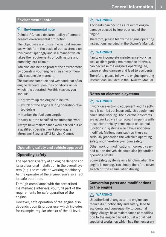
Environmental note
H Environmental noteDaimler AG has a declared policy of compre-hensive environmental protection.The objectives are to use the natural resour-ces which form the basis of our existence onthis planet sparingly and in a manner whichtakes the requirements of both nature andhumanity into account.You also can help to protect the environmentby operating your engine in an environmen-tally responsible manner.The fuel consumption and wear and tear of anengine depend upon the conditions underwhich it is operated. For this reason, youshould:Rnot warm up the engine in neutralRswitch off the engine during operation-rela-
ted delaysRmonitor the fuel consumptionRcarry out the specified maintenance work.Always have maintenance work carried out ata qualified specialist workshop, e.g. aMercedes-Benz or MTU Service Centre.
Operating safety and vehicle approval
Operating safetyThe operating safety of an engine depends onits professional installation in the overall sys-tem (e.g. the vehicle or working machinery).As the operator of the engine, you also affectits safe operation.Through compliance with the prescribedmaintenance intervals, you fulfil part of therequirements for safe operation of theengine.However, safe operation of the engine alsodepends upon its proper use, which includes,for example, regular checks of the oil level.
G WARNINGAccidents can occur as a result of enginedamage caused by improper use of theengine.Therefore, please follow the engine operatinginstructions included in the Owner's Manual.
G WARNINGFaulty or incomplete maintenance work, aswell as disregarded maintenance intervals,can decrease the engine's operating life,cause engine damage and lead to accidents.Therefore, please follow the engine operatinginstructions included in the Owner's Manual.
Notes on electronic systems
G WARNINGIf work on electronic equipment and its soft-ware is carried out incorrectly, this equipmentcould stop working. The electronic systemsare networked via interfaces. Tampering withthese electronic systems could cause mal-functions in systems which have not beenmodified. Malfunctions such as these canseriously jeopardise the vehicle's operatingsafety and therefore your own safety.Other work or modifications incorrectly car-ried out on the vehicle could also jeopardiseoperating safety.Some safety systems only function when theengine is running. You should therefore neverswitch off the engine when driving.
Conversion parts and modificationsto the engine
G WARNINGUnauthorised changes to the engine canreduce its functionality and safety, lead toaccidents and consequently to personalinjury. Always have maintenance or modifica-tion to the engine carried out at a qualifiedspecialist workshop which has the necessary
General information 7
Z
specialist knowledge and tools to carry outthe work required. Mercedes-Benz recom-mends that you use a Mercedes-Benz or MTUService Centre for this purpose.
! Unauthorised intervention in the injectionsystem and the engine electronics canaffect the performance and emissions ofthe engine. Compliance with factory set-tings and legal environmental protectionconditions can then no longer be guaran-teed.
The implied warranty does not cover damageresulting from unauthorised modifications tothe engine.
Safety/emergency running programThe engine is equipped with an electroniccontrol system, which monitors both theengine and itself (self-diagnosis).When the electronic control system detects amalfunction, one of the following measures isautomatically implemented after an appraisalof the malfunction:RThe corresponding warning lamp displays
the faults occurring during operation(Y page 25).RIn conjunction with the electronic engine
control, fault codes can be shown on a dis-play.RThe system switches to a suitable backup
function for the continued, albeit restrictedoperation of the engine (e.g. constantemergency running speed).
G WARNINGIf maintenance and repair work on the engineis not carried out correctly, the operation andsafety may be affected, which can result inaccidents and personal injury.Always have work on or modifications to theengine carried out at a qualified specialistworkshop that has the necessary specialskills and tools for the work required.
Mercedes-Benz recommends a Mercedes-Benz or MTU Service Centre.
The Daimler diagnostic tester can beattached to the 14-pin diagnostic socket onthe equipment, or to the service plug accord-ing to the EU Directive. Both the malfunctionmessage memory and the saved engine datacan be read by this device.
Warning lamp electronics (example)
Genuine Mercedes-Benz partsMake sure of the suitability of the replace-ment parts for your engine. Parts that lead toa modification of the engine/vehicle/equip-ment are considered in many countries torender the general operating permit invalid.Such modifications include, for example:Rmodifications that change the approved
equipment type/vehicle type, as defined bythe general operating permit.Rmodifications that could endanger road
users or persons in the vicinity of the vehi-cle/equipment.Rmodifications that change the exhaust or
noise level.The use of unapproved parts can adverselyaffect safety levels.
H Environmental noteFor more economic repairs, Mercedes-Benzoffers Mercedes-Benz reconditioned assem-bly and parts as part of the recycling process.The same quality standards and warrantyapply as to new parts.
8 General information
You can find more information on recommen-ded conversion parts and accessories, as wellas permitted technical modifications at aMercedes-Benz or MTU Service Centre(Y page 11).Always state the engine number with themodel designation when ordering genuineMercedes-Benz parts. You can find the num-bers on the identification plate of your engine(Y page 100) and on the engine data card(Y page 100).
BlueTec® exhaust gas aftertreatmentThe engines meet the requirements of therelevant emissions level and are correspond-ingly certified.Compliance with emissions laws and regula-tions is a condition of the operating permit forthe vehicle/equipment.Engines with BlueTec® exhaust gas after-treatment must be operated with AdBlue®/DEF in order to meet the emissions laws andregulations.The operating permit is invalidated if the vehi-cle/equipment is operated without AdBlue®/DEF. The legal consequence of this is thatoperation of the vehicle/equipment is no lon-ger permitted. This may be an offence or abreach of road traffic regulations in certaincountries. Special concessions grantedeither at the time of purchase or to reduceoperating costs of the vehicle/equipment,e.g. reduced taxes or tolls, may also be ren-dered retroactively invalid. This can be thecase in the country of registration. Or also inanother country where you operate the vehi-cle/equipment.
Legal requirementsIf the engine/vehicle/equipment is not oper-ated within the limits of the emissions lawsand regulations, it can lead to sanctions.
This normally affects the following operatingstates:Rdriving without AdBlue®/DEFRthe permissible nitrogen oxide (NOx)
thresholds are exceededRthere is a fault or emissions-relevant mal-
function in the monitoring or exhaust gasaftertreatment system
You can find details in the “Engine diagnosticsindicator lamp” section(Y page 94).
Fault detected in the monitoring systemIf the monitoring system detects a fault in theBlueTec® exhaust gas aftertreatment, opera-tion is limited in accordance with the relevantregulations (Y page 37).
Correct useThe engine may only be installed as contrac-tually specified.The manufacturer of the end product isresponsible for the correct installation andcompatibility of the engine in the overall sys-tem.The engine may not be modified. If the engineis modified, Mercedes-Benz and MTU do notaccept responsibility for any damage arisingas a result.Correct use of the engine requires adherenceto the instructions in this Owner's Manual.This also requires compliance with the main-tenance intervals and the professional exe-cution of maintenance work in accordancewith this Owner's Manual.
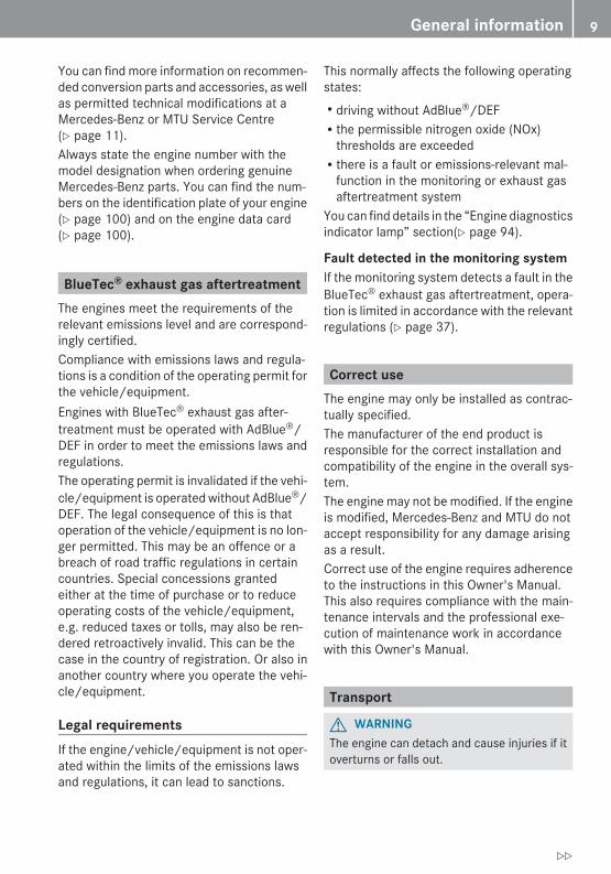
Transport
G WARNINGThe engine can detach and cause injuries if itoverturns or falls out.
General information 9
Z
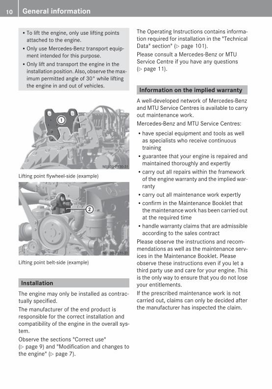
RTo lift the engine, only use lifting pointsattached to the engine.ROnly use Mercedes-Benz transport equip-
ment intended for this purpose.ROnly lift and transport the engine in the
installation position. Also, observe the max-imum permitted angle of 30° while liftingthe engine in and out of vehicles.
Lifting point flywheel-side (example)
Lifting point belt-side (example)
InstallationThe engine may only be installed as contrac-tually specified.The manufacturer of the end product isresponsible for the correct installation andcompatibility of the engine in the overall sys-tem.Observe the sections "Correct use"(Y page 9) and "Modification and changes tothe engine" (Y page 7).
The Operating Instructions contains informa-tion required for installation in the "TechnicalData" section" (Y page 101).Please consult a Mercedes-Benz or MTUService Centre if you have any questions(Y page 11).
Information on the implied warrantyA well-developed network of Mercedes-Benzand MTU Service Centres is available to carryout maintenance work.Mercedes-Benz and MTU Service Centres:Rhave special equipment and tools as well
as specialists who receive continuoustrainingRguarantee that your engine is repaired and
maintained thoroughly and expertlyRcarry out all repairs within the framework
of the engine warranty and the implied war-rantyRcarry out all maintenance work expertlyRconfirm in the Maintenance Booklet that
the maintenance work has been carried outat the required timeRhandle warranty claims that are admissible
according to the sales contractPlease observe the instructions and recom-mendations as well as the maintenance serv-ices in the Maintenance Booklet. Pleaseobserve these instructions even if you let athird party use and care for your engine. Thisis the only way to ensure that you do not loseyour entitlements.If the prescribed maintenance work is notcarried out, claims can only be decided afterthe manufacturer has inspected the claim.
10 General information
During the engine warranty period in particu-lar, have the prescribed maintenance servicecarried out as follows:RregularlyRpunctuallyRat a qualified specialist workshop which
has the necessary specialist knowledgeand tools to carry out the work required.Mercedes-Benz recommends that you usea Mercedes-Benz or MTU Service Centrefor this purpose. In particular, work rele-vant to safety or on safety-related systemsmust be carried out at a qualified specialistworkshop.
If there are legal requirements on exhaust gasaftertreatment, please note that:Rmaintenance on the engines must be car-
ried out according to specific regulationsand using special measuring devices.Rit is prohibited to modify or tamper with
components relevant to emissions.All Mercedes-Benz and MTU Service Centresare aware of the relevant regulations.Maintenance work does not include repairwork. Repair work requires a separate order.You may also consult a Mercedes-Benz orMTU Service Centre for further information.
Qualified specialist workshopA qualified specialist workshop has the nec-essary specialist knowledge, tools and quali-fications to carry out the work required on theengine to a professional standard. This isespecially important for work relevant tosafety.A qualified specialist workshop must carryout the required service, maintenance andrepair work and document it according to thespecifications of Daimler AG. Failure to com-ply with these specifications could lead to theloss of warranty entitlements.Mercedes-Benz recommends that you use aMercedes-Benz or MTU Service Centre.
Always have the following work on the vehiclecarried out at a qualified specialist workshop:Rwork relevant to safetyRservice and maintenance workRrepair workRmodifications such as installations or con-
versionsRwork on electronic componentsPlease have warranty and ex gratia work car-ried out at authorised workshops/ServiceCentres.RFor on-highway applications, contact a
Mercedes-Benz Service Centre.RFor off-highway applications, contact an
MTU or MTU-authorised Mercedes-Benzpartner.
General information 11
Z

12

Exterior view ....................................... 14General information ............................ 21
13
At a
gla
nce
Exterior view
Engine overview
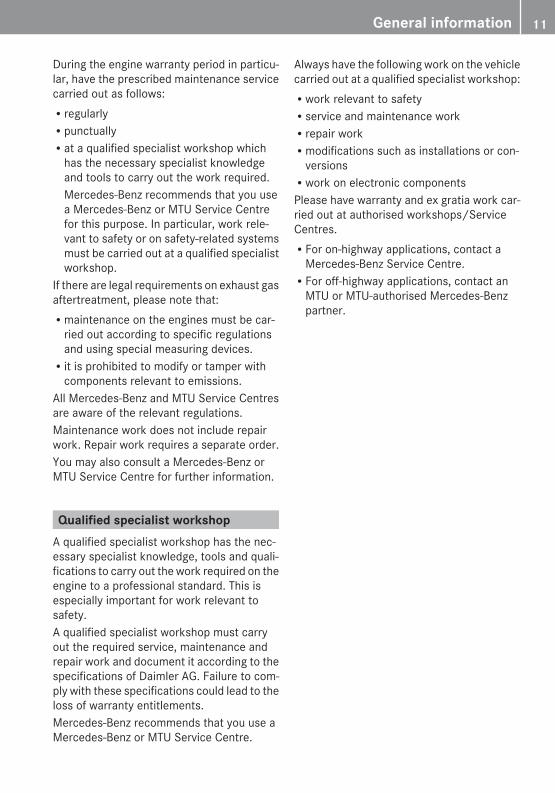
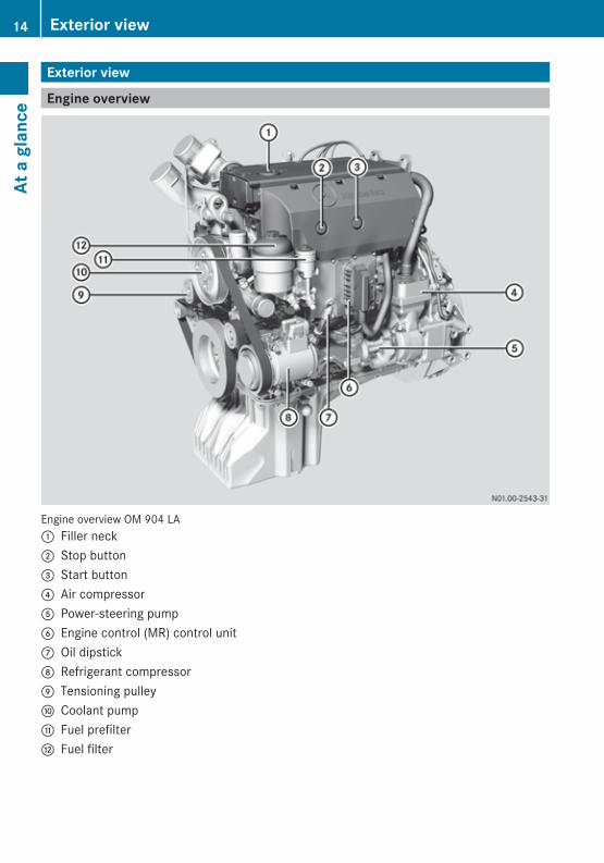
Engine overview OM 904 LA: Filler neck; Stop button= Start button? Air compressorA Power-steering pumpB Engine control (MR) control unitC Oil dipstickD Refrigerant compressorE Tensioning pulleyF Coolant pumpG Fuel prefilterH Fuel filter
14 Exterior viewAt
a g
lanc
e
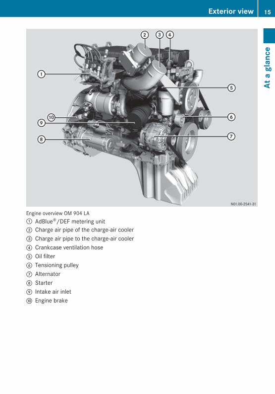
Engine overview OM 904 LA: AdBlue®/DEF metering unit; Charge air pipe of the charge-air cooler= Charge air pipe to the charge-air cooler? Crankcase ventilation hoseA Oil filterB Tensioning pulleyC AlternatorD StarterE Intake air inletF Engine brake
Exterior view 15
At a
gla
nce
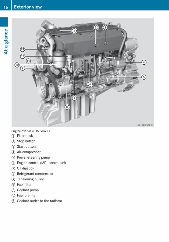
Engine overview OM 906 LA: Filler neck; Stop button= Start button? Air compressorA Power-steering pumpB Engine control (MR) control unitC Oil dipstickD Refrigerant compressorE Tensioning pulleyF Fuel filterG Coolant pumpH Fuel prefilterI Coolant outlet to the radiator
16 Exterior viewAt
a g
lanc
e
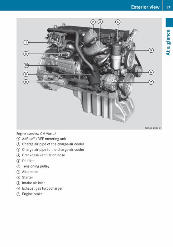
Engine overview OM 906 LA: AdBlue®/DEF metering unit; Charge air pipe of the charge-air cooler= Charge air pipe to the charge-air cooler? Crankcase ventilation hoseA Oil filterB Tensioning pulleyC AlternatorD StarterE Intake air inletF Exhaust gas turbochargerG Engine brake
Exterior view 17
At a
gla
nce
Sensors overview
Sensors, general
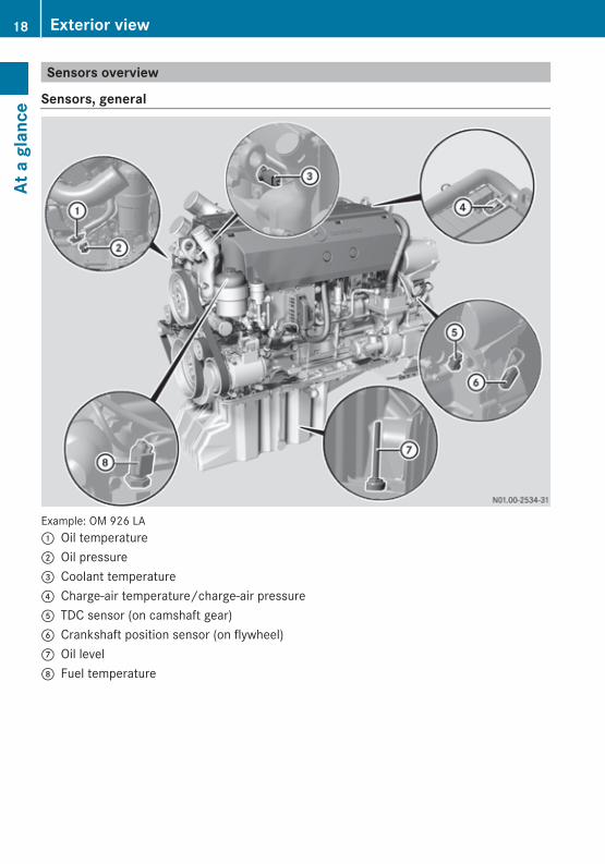
Example: OM 926 LA: Oil temperature; Oil pressure= Coolant temperature? Charge-air temperature/charge-air pressureA TDC sensor (on camshaft gear)B Crankshaft position sensor (on flywheel)C Oil levelD Fuel temperature
18 Exterior viewAt
a g
lanc
e
AdBlue®/DEF components
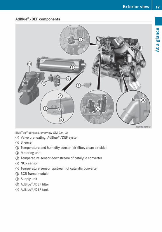
BlueTec® sensors, overview OM 924 LA: Valve preheating, AdBlue®/DEF system; Silencer= Temperature and humidity sensor (air filter, clean air side)? Metering unitA Temperature sensor downstream of catalytic converterB NOx sensorC Temperature sensor upstream of catalytic converterD SCR frame moduleE Supply unitF AdBlue®/DEF filterG AdBlue®/DEF tank
Exterior view 19
At a
gla
nce
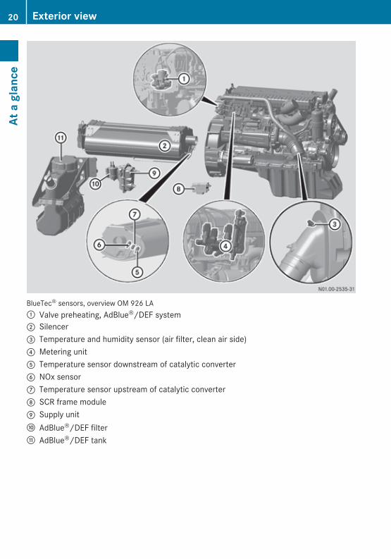
BlueTec® sensors, overview OM 926 LA: Valve preheating, AdBlue®/DEF system; Silencer= Temperature and humidity sensor (air filter, clean air side)? Metering unitA Temperature sensor downstream of catalytic converterB NOx sensorC Temperature sensor upstream of catalytic converterD SCR frame moduleE Supply unitF AdBlue®/DEF filterG AdBlue®/DEF tank
20 Exterior viewAt
a g
lanc
e
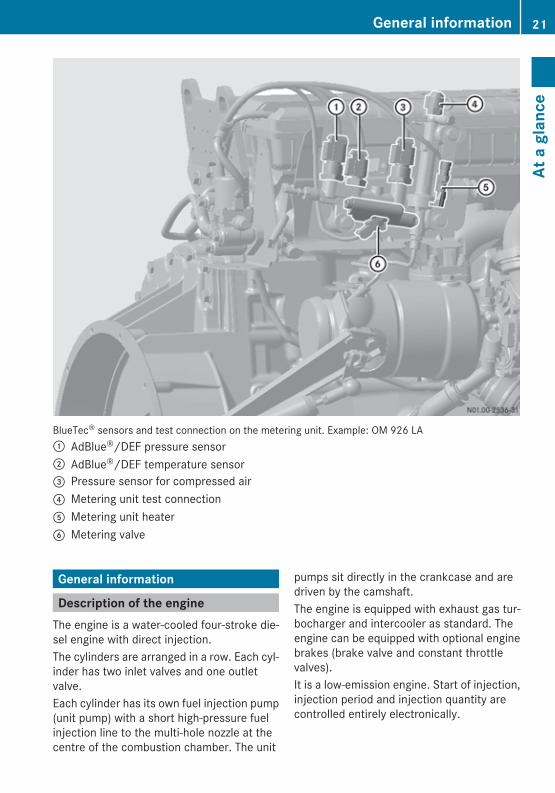
BlueTec® sensors and test connection on the metering unit. Example: OM 926 LA: AdBlue®/DEF pressure sensor; AdBlue®/DEF temperature sensor= Pressure sensor for compressed air? Metering unit test connectionA Metering unit heaterB Metering valve
General information
Description of the engineThe engine is a water-cooled four-stroke die-sel engine with direct injection.The cylinders are arranged in a row. Each cyl-inder has two inlet valves and one outletvalve.Each cylinder has its own fuel injection pump(unit pump) with a short high-pressure fuelinjection line to the multi-hole nozzle at thecentre of the combustion chamber. The unit
pumps sit directly in the crankcase and aredriven by the camshaft.The engine is equipped with exhaust gas tur-bocharger and intercooler as standard. Theengine can be equipped with optional enginebrakes (brake valve and constant throttlevalves).It is a low-emission engine. Start of injection,injection period and injection quantity arecontrolled entirely electronically.
General information 21
At a
gla
nce
Electronic drive controlThe engine has a fully electronic control sys-tem which, along with the engine and its asso-ciated sensors, consists of the following com-ponents:Rthe engine control unit (MR) andRthe drive control unit (FR) and/or other
vehicle-specific control units, e.g. ADMRSCR frame module (only for engines with
BlueTec® exhaust gas aftertreatment)The control units are interconnected by aCAN line (Controller Area Network line) whichfacilitates the exchange of all necessary data.In addition to the engine and the BlueTec®
exhaust gas aftertreatment, the electronicengine control also monitors itself. Depend-ing on the malfunctions/failures that occur,a safety and emergency mode (Y page 8) maybe automatically selected.For vehicle engines, the electronic enginecontrol only allows the engine to be startedwhen the transmission is in neutral.
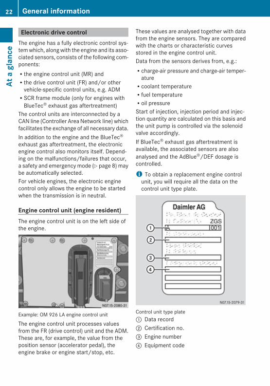
Engine control unit (engine resident)The engine control unit is on the left side ofthe engine.
Example: OM 926 LA engine control unit
The engine control unit processes valuesfrom the FR (drive control) unit and the ADM.These are, for example, the value from theposition sensor (accelerator pedal), theengine brake or engine start/stop, etc.
These values are analysed together with datafrom the engine sensors. They are comparedwith the charts or characteristic curvesstored in the engine control unit.Data from the sensors derives from, e.g.:Rcharge-air pressure and charge-air temper-
atureRcoolant temperatureRfuel temperatureRoil pressureStart of injection, injection period and injec-tion quantity are calculated on this basis andthe unit pump is controlled via the solenoidvalve accordingly.If BlueTec® exhaust gas aftertreatment isavailable, the associated sensors are alsoanalysed and the AdBlue®/DEF dosage iscontrolled.
i To obtain a replacement engine controlunit, you will require all the data on thecontrol unit type plate.
Control unit type plate: Data record; Certification no.= Engine number? Equipment code
22 General informationAt
a g
lanc
e
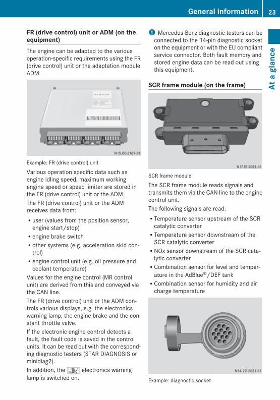
FR (drive control) unit or ADM (on theequipment)The engine can be adapted to the variousoperation-specific requirements using the FR(drive control) unit or the adaptation moduleADM.
Example: FR (drive control) unit
Various operation specific data such asengine idling speed, maximum workingengine speed or speed limiter are stored inthe FR (drive control) unit or the ADM.The FR (drive control) unit or the ADMreceives data from:Ruser (values from the position sensor,
engine start/stop)Rengine brake switchRother systems (e.g. acceleration skid con-
trol)Rengine control unit (e.g. oil pressure and
coolant temperature)Values for the engine control (MR controlunit) are derived from this and conveyed viathe CAN line.The FR (drive control) unit or the ADM con-trols various displays, e.g. the electronicswarning lamp, the engine brake and the con-stant throttle valve.If the electronic engine control detects afault, the fault code is saved in the controlunits. It can be read out with the correspond-ing diagnostic testers (STAR DIAGNOSIS orminidiag2).In addition, the ^ electronics warninglamp is switched on.
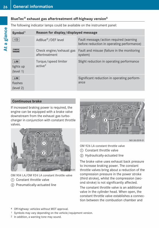
i Mercedes-Benz diagnostic testers can beconnected to the 14-pin diagnostic socketon the equipment or with the EU compliantservice connector. Both fault memory andstored engine data can be read out usingthis equipment.
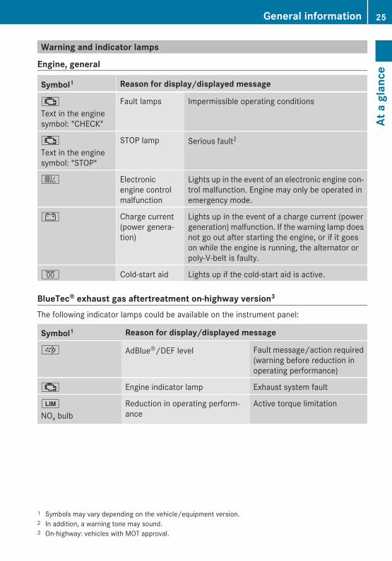
SCR frame module (on the frame)
SCR frame module
The SCR frame module reads signals andtransmits them via the CAN line to the enginecontrol unit.The following signals are read:RTemperature sensor upstream of the SCR
catalytic converterRTemperature sensor downstream of the
SCR catalytic converterRNOx sensor downstream of the SCR cata-
lytic converterRCombination sensor for level and temper-
ature in the AdBlue®/DEF tankRCombination sensor for humidity and air
charge temperature
Example: diagnostic socket
General information 23
At a
gla
nce
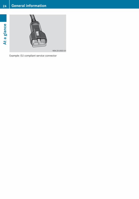
Example: EU compliant service connector
24 General informationAt
a g
lanc
e
Warning and indicator lamps
Engine, general
Symbol1 Reason for display/displayed message
;
Text in the enginesymbol: "CHECK"
Fault lamps Impermissible operating conditions
;
Text in the enginesymbol: "STOP"
STOP lamp Serious fault2
k Electronicengine controlmalfunction
Lights up in the event of an electronic engine con-trol malfunction. Engine may only be operated inemergency mode.
# Charge current(power genera-tion)
Lights up in the event of a charge current (powergeneration) malfunction. If the warning lamp doesnot go out after starting the engine, or if it goeson while the engine is running, the alternator orpoly-V-belt is faulty.
% Cold-start aid Lights up if the cold-start aid is active.
BlueTec® exhaust gas aftertreatment on-highway version3
The following indicator lamps could be available on the instrument panel:
Symbol1 Reason for display/displayed message
þ AdBlue®/DEF level Fault message/action required(warning before reduction inoperating performance)
; Engine indicator lamp Exhaust system fault
È
NOx bulbReduction in operating perform-ance
Active torque limitation
1 Symbols may vary depending on the vehicle/equipment version.2 In addition, a warning tone may sound.3 On-highway: vehicles with MOT approval.
General information 25
At a
gla
nce
BlueTec® exhaust gas aftertreatment off-highway version4
The following indicator lamps could be available on the instrument panel:
Symbol1 Reason for display/displayed message
þ AdBlue®/DEF level Fault message/action required (warningbefore reduction in operating performance)
! Check engine/exhaust gasaftertreatment
Fault and misuse (failure in the monitoringsystem)
È
lights up(level 1)
Torque/speed limiteractive2
Slight reduction in operating performance
È
flashes(level 2)
Significant reduction in operating perform-ance
Continuous brakeIf increased braking power is required, theengine can be equipped with a brake valvedownstream from the exhaust gas turbo-charger in conjunction with constant throttlevalves.
OM 904 LA/OM 924 LA constant throttle valve: Constant throttle valve; Pneumatically-actuated line
OM 926 LA constant throttle valve: Constant throttle valve; Hydraulically-actuated line
The brake valve uses exhaust back pressureto increase braking power. The constantthrottle valves bring about a reduction of thecompression pressure in the power stroke(third stroke), whilst the compression (sec-ond stroke) is not significantly affected.The constant throttle valve is an additionalvalve in the cylinder head. When open, theconstant throttle valve establishes a connec-tion between the combustion chamber and
4 Off-highway: vehicles without MOT approval.1 Symbols may vary depending on the vehicle/equipment version.2 In addition, a warning tone may sound.
26 General informationAt
a g
lanc
e
exhaust port. This brings about the desireddecompression during the power stroke.When the engine brake is activated, the con-stant throttle valves are opened. ForOM 904/OM 924 engines, the actuation ispneumatic. For OM 906/OM 926 engines,the actuation is hydraulic. The brake valve onthe exhaust gas turbocharger is also closed.The engine brake is actuated by the FR (drivecontrol) unit (Y page 23) or the ADM.The engine brake is always deactivated below900 rpm. This prevents the engine from stall-ing. The engine brake is automatically deac-tivated even if the position sensor (e.g. accel-erator pedal) is in use.
i In emergency mode (constant enginespeed), the engine brake can only be acti-vated in overrun mode at increased enginespeed. Once the constant engine speed isreached, the engine brake is automaticallydeactivated again.
Cold-start aidThe cold-start aid makes it easier to start theengine at low outside temperatures (below–15 †); it is activated when the outside tem-perature falls below –4 †.
H Environmental noteAt outside temperatures below about –4 †the cold-start aid minimises emissions (afterstarting the engine). In addition, it reduces theload on the starter motor and batteries andenables the engine to be started more rapidly.For this reason you should only start theengine after the % indicator lamp goes out.
X To activate the cold-start aid: turn thevehicle key to the drive position in the igni-tion lock.The % indicator lamp lights up in theinstrument panel.
X After the % indicator lamp goes out,start the engine within 30 seconds.
The cold-start aid is automatically deactiva-ted if:Rthe engine is not started within 30 seconds
of the % indicator lamp going out.Rthe engine is started while the % indi-
cator lamp is still lit.Rthe coolant temperature reaches around
0 † while the engine is running.At a coolant temperature above approx-imately –4 †, the % indicator lamp goesout after approximately 2 seconds (functioncheck). At a coolant temperature belowapproximately –4 †, the % indicator lampgoes out after approximately 20 seconds.Have the cold-start aid checked and repairedat a qualified specialist workshop. Mercedes-Benz recommends that you use a Mercedes-Benz or MTU Service Centre for this purpose(Y page 11). Work relevant to safety or onsafety-related systems must be carried out ata qualified specialist workshop.
General information 27
At a
gla
nce
Z

28

Safety precautions .............................. 30Staff qualifications ............................. 30Organisational measures ................... 30
29
Safe
ty
Safety precautions
Damage to the engine can also lead to per-sonal injury. In order to avoid engine damage,the following safety precautions must beadhered to.
Safety precautionsROnly start the engine when the batteries
are firmly attached.RDo not disconnect the batteries when the
engine is running.RDo not use a rapid charger to start the
engine.ROnly perform the jump-starting proce-
dure with separate batteries.RNote, the battery terminals must be dis-
connected when rapid charging the bat-teries.RObserve the operating instructions of the
rapid battery charger.RPlease note, when carrying out electric
welding work, that the batteries must bedisconnected and both of the cables ("+"and "-") must be firmly attached to eachother.RThe control unit connectors may only be
connected/disconnected when the elec-trical system is switched off.RIncorrect control unit-power supply
polarity (e.g. by connecting up the bat-teries incorrectly) can cause irreparabledamage to the control units.RTighten diesel injection system connec-
tions to the prescribed tightening torque.RIf temperatures above 80 † are to be
expected (e.g. in a drying oven), the con-trol unit on the engine must be removed.ROnly use the appropriate testing probes
when taking measurements from electri-cal connectors (e.g. a Mercedes-Benzconnection set). Telephones and two-way radio devices that are not connectedto an external aerial, can cause malfunc-
tions in the vehicle electronics and thusendanger the operating safety of theengine.
Staff qualifications
G WARNINGIf maintenance and repair work on the engineis not carried out correctly, the operation andsafety may be affected, which can result inaccidents and personal injury.Always have work on or modifications to theengine carried out at a qualified specialistworkshop that has the necessary specialskills and tools for the work required.Mercedes-Benz recommends a Mercedes-Benz or MTU Service Centre.
The engine should only be operated, main-tained and repaired by trained personnel whohave been briefed and authorised by the oper-ator. The minimum legal age for personnelcarrying out maintenance and repair workmust be observed.
Organisational measures
The responsibilities for operation, mainte-nance and repairs are to be determined by theoperator. Give the Operating Instructions andthe Maintenance Booklet to the personnelthat are charged with operating or carryingout work on the engine.
G WARNINGBefore operating the engine, please readthese Operating Instructions. Please also firstread the operating instructions of the vehicleor the machine to which the engine is fitted.You may not recognise dangers and mayinjure yourself or others.
Instruct personnel on how to operate theengine using the Operating Instructions.When doing so, put special emphasis onsafety-relevant information. This is particu-
30 Organisational measuresSa
fety

larly important for personnel that only workoccasionally on the engine.Always keep the Operating Instructions andthe Maintenance Booklet readily accessible,in the area of engine operation.In addition to the Operating Instructions,other general, country-specific, legal andother binding regulations on accident preven-tion and environmental protection must beadhered to.
Organisational measures 31
Safe
ty
Z

32
Operation ............................................. 34Continuous brake ................................ 40Driving tips .......................................... 40Refuelling ............................................. 41Winter operation ................................. 43
33
Driv
ing
mod
e/w
orki
ng m
ode
Operation
Preparation for operationAt the factory, the engine is filled with 5W30initial operation oil that complies with Sheet225.6 of the Mercedes-Benz Specificationsfor Service Products.These high-quality engine oils are beneficialto the running-in process. They also allow youto make the first oil change in accordancewith the applicable oil change intervals fornormal operation. This eliminates the needfor special initial operation oils and the addi-tional oil change otherwise required.The extended maintenance intervals can onlybe observed if engine oils complying withSheet 228.5 of the Mercedes-Benz Specifi-cations for Service Products are used.
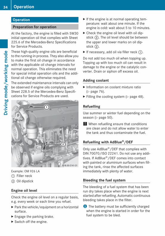
Example: OM 926 LA: Filler neck; Oil dipstick
Engine oil levelCheck the engine oil level on a regular basis,e.g. every week or each time you refuel.X Park the vehicle/equipment on a horizontal
surface.X Engage the parking brake.X Switch off the engine.
X If the engine is at normal operating tem-perature: wait about one minute. If theengine is cold: wait about 5 to 10 minutes.
X Check the engine oil level with oil dip-stick ;. The oil level should be betweenthe upper and lower marks on oil dip-stick ;.
X If necessary, add oil via filler neck :.
Do not add too much oil when topping up.Topping up with too much oil can result indamage to the engine or the catalytic con-verter. Drain or siphon off excess oil.
Adding coolantX Information on coolant mixture ratio
(Y page 76).X Filling the cooling system (Y page 48).
RefuellingUse summer or winter fuel depending on theseason (Y page 50).
! When refuelling ensure that conditionsare clean and do not allow water to enterthe tank and thus contaminate the fuel.
Refuelling with AdBlue®/DEFOnly use AdBlue®/DEF that complies withDIN 70070/ISO 22241. Do not use any addi-tives. If AdBlue®/DEF comes into contactwith painted or aluminium surfaces when fill-ing the tank, rinse the affected surfacesimmediately with plenty of water.
Bleeding the fuel systemThe bleeding of a fuel system that has beenrun dry takes place when the engine is nextstarted after refuelling. Automatic continuousbleeding takes place in the filter.
i The battery must be sufficiently chargedwhen the engine is started in order for thefuel system to be bled.
34 OperationDr
ivin
g m
ode/
wor
king
mod
e
i Use the integrated hand pump(Y page 68) to bleed the heated-fuel pre-filter with water separator mounted on thevehicle or equipment.
Starting the engine for the first time
PreparationCarry out the work listed under "Preparing foroperation" before operating the engine forthe first time (Y page 34).Observe the information contained in theequipment/vehicle manufacturer's operatinginstructions.X Connect a power supply.X Switch on the ignition.X Start the engine using the key in the ignition
lock or the start button on the engine. Donot depress the accelerator or clutch pedalwhile doing so. For equipment, the neutralposition must be engaged.
As a safety function, the electronic enginecontrol system facilitates the possibility ofonly allowing the engine to be started whenthe transmission or equipment is in neutral.
G WARNINGMake sure you do not touch any hot or movingengine components (e.g. exhaust manifold,poly-V-belt, fan) when the engine is running.You could injure yourself.Be aware of the road and traffic situationwhen working on public roads and secureyour position accordingly.
G WARNINGThere is a danger of limbs being caught, pulledin and thereby crushed or severed by rotatingengine parts.
Therefore you should:Rkeep a safe distance between yourself and
rotating engine parts, including when theengine is being started.Rwait until all engine parts have stopped
moving before carrying out any work on theengine.Rwear work clothing which is fastened and
close-fitting. Wear a hair net if necessary.Remove jewellery such as watches andnecklaces.
G WARNINGWhen opening the coolant expansion tank,there is a risk of scalding due to hot coolantspraying out. The cooling system and coolantexpansion tank are pressurised when theengine is at operating temperature. Weargloves and eye protection.Only open the coolant expansion tank whenthe coolant temperature is below 50 †.
G WARNINGCoolant contains glycol and is therefore toxic.Do not swallow the coolant. See a doctorimmediately if you swallow coolant.Make sure that coolant does not come intocontact with skin, eyes or clothing. In case ofcontact with eyes, rinse immediately withplenty of clean water. Clean affected areas ofskin and clothing with soap and water imme-diately. Change any affected clothing imme-diately.
Starting the engine for the first timeX To check coolant level: leave the engine
running at a moderate engine speed foraround five minutes.
X If the coolant temperature is less than50 †, check the coolant level again. Addcoolant.
If a heating system is connected to the cool-ing system, all heating system valves must beopened while the cooling system is being top-ped up. Otherwise, there might be too little
Operation 35
Driv
ing
mod
e/w
orki
ng m
ode
Z
coolant in the coolant circuit after it is filled.Only close the heating system valves once theengine has been running for a brief periodand, where applicable, the coolant has beentopped up.X Check the engine for leaks.X Check all hose fittings, hose clamps and
pipe connections on the engine as well asthe oil feed and return lines on the exhaustgas turbocharger for leaks and firm seating.
X Around five minutes after switching off theengine, check the engine oil level with thedipstick.The oil level should be between the upperand lower marks on the dipstick.
X Check the seating of the bracket securedto the engine.
X Check the tightness of bolts on the exhaustmanifold, engine mountings, coolant pump,starter motor and air compressor.
Starting and stopping the engine withthe key
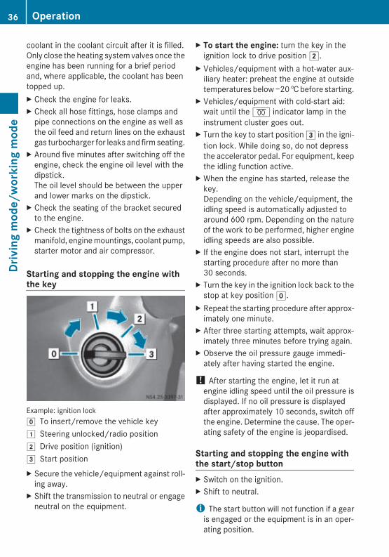
Example: ignition lockg To insert/remove the vehicle key1 Steering unlocked/radio position2 Drive position (ignition)3 Start positionX Secure the vehicle/equipment against roll-
ing away.X Shift the transmission to neutral or engage
neutral on the equipment.
X To start the engine: turn the key in theignition lock to drive position 2.
X Vehicles/equipment with a hot-water aux-iliary heater: preheat the engine at outsidetemperatures below −20 † before starting.
X Vehicles/equipment with cold-start aid:wait until the % indicator lamp in theinstrument cluster goes out.
X Turn the key to start position 3 in the igni-tion lock. While doing so, do not depressthe accelerator pedal. For equipment, keepthe idling function active.
X When the engine has started, release thekey.Depending on the vehicle/equipment, theidling speed is automatically adjusted toaround 600 rpm. Depending on the natureof the work to be performed, higher engineidling speeds are also possible.
X If the engine does not start, interrupt thestarting procedure after no more than30 seconds.
X Turn the key in the ignition lock back to thestop at key position g.
X Repeat the starting procedure after approx-imately one minute.
X After three starting attempts, wait approx-imately three minutes before trying again.
X Observe the oil pressure gauge immedi-ately after having started the engine.
! After starting the engine, let it run atengine idling speed until the oil pressure isdisplayed. If no oil pressure is displayedafter approximately 10 seconds, switch offthe engine. Determine the cause. The oper-ating safety of the engine is jeopardised.
Starting and stopping the engine withthe start/stop buttonX Switch on the ignition.X Shift to neutral.
i The start button will not function if a gearis engaged or the equipment is in an oper-ating position.
36 OperationDr
ivin
g m
ode/
wor
king
mod
e
Engine with one button
X To start the engine: press start/stop but-ton :.The engine starts and runs at engine idlingspeed.
X To start the engine and increase the engine speed: press and hold start/stopbutton :.The engine starts and runs at engine idlingspeed. After about three seconds, theengine speed increases.
X Hold down start/stop button : until thedesired engine speed is reached.After releasing start/stop button :, theengine continues to run at the currently setspeed. The engine speed can be increasedup to the limiting speed.
X To stop the engine: press start/stop but-ton : again.The engine switches off.
Engine with two buttons
X To start the engine: press start but-ton ;.The engine starts and runs at engine idlingspeed.
X To increase the engine speed: while theengine is running, press start button ;again and hold it down until the desiredengine speed is reached.After releasing start button ;, the enginecontinues to run at the currently set speed.The engine speed can be increased up tothe limiting speed.
X To stop the engine: while the engine isrunning, press stop button :.The engine switches off.
X To turn the engine over without starting it: press and hold start button ; and stopbutton : at the same time.The engine turns over without starting.
X Release start button ; and stop but-ton :.The engine remains at a standstill.
Operational monitoring
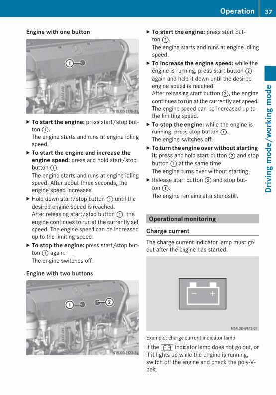
Charge currentThe charge current indicator lamp must goout after the engine has started.
Example: charge current indicator lamp
If the # indicator lamp does not go out, orif it lights up while the engine is running,switch off the engine and check the poly-V-belt.
Operation 37
Driv
ing
mod
e/w
orki
ng m
ode
Z
! Make sure that the poly-V-belt contactsurfaces are not damaged (e.g. torn), oilyor glazed, as this could cause the poly-V-belt to slip. Do not run the engine withouta poly-V-belt. Otherwise, the alternator andcoolant pump are not driven, which resultsin engine damage.
Further information can be found in the“Checking the poly-V-belt for wear”(Y page 66) and “Replacing the poly-V-belt”sections (Y page 97).
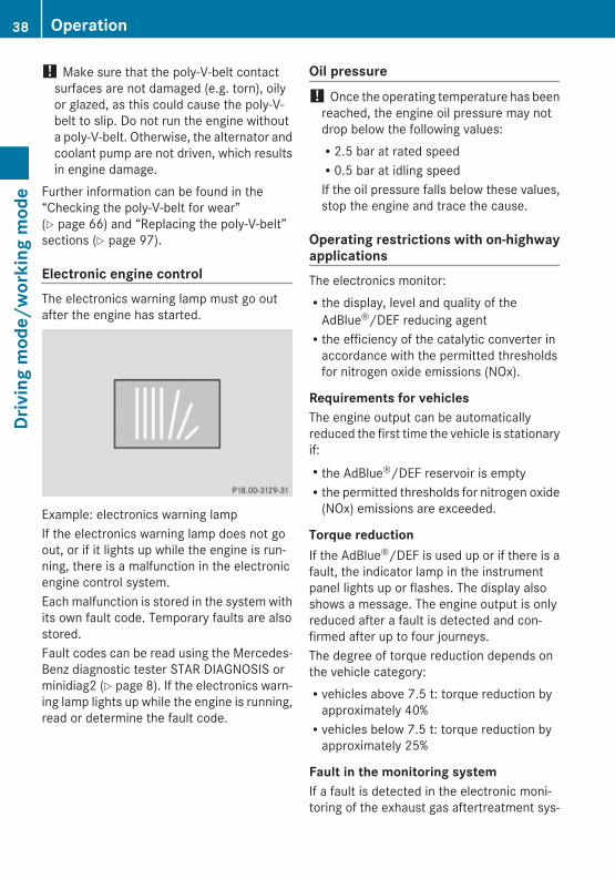
Electronic engine controlThe electronics warning lamp must go outafter the engine has started.
Example: electronics warning lampIf the electronics warning lamp does not goout, or if it lights up while the engine is run-ning, there is a malfunction in the electronicengine control system.Each malfunction is stored in the system withits own fault code. Temporary faults are alsostored.Fault codes can be read using the Mercedes-Benz diagnostic tester STAR DIAGNOSIS orminidiag2 (Y page 8). If the electronics warn-ing lamp lights up while the engine is running,read or determine the fault code.
Oil pressure! Once the operating temperature has been
reached, the engine oil pressure may notdrop below the following values:R2.5 bar at rated speedR0.5 bar at idling speedIf the oil pressure falls below these values,stop the engine and trace the cause.
Operating restrictions with on-highwayapplicationsThe electronics monitor:Rthe display, level and quality of the
AdBlue®/DEF reducing agentRthe efficiency of the catalytic converter in
accordance with the permitted thresholdsfor nitrogen oxide emissions (NOx).
Requirements for vehiclesThe engine output can be automaticallyreduced the first time the vehicle is stationaryif:Rthe AdBlue®/DEF reservoir is emptyRthe permitted thresholds for nitrogen oxide
(NOx) emissions are exceeded.
Torque reductionIf the AdBlue®/DEF is used up or if there is afault, the indicator lamp in the instrumentpanel lights up or flashes. The display alsoshows a message. The engine output is onlyreduced after a fault is detected and con-firmed after up to four journeys.The degree of torque reduction depends onthe vehicle category:Rvehicles above 7.5 t: torque reduction by
approximately 40%Rvehicles below 7.5 t: torque reduction by
approximately 25%
Fault in the monitoring systemIf a fault is detected in the electronic moni-toring of the exhaust gas aftertreatment sys-
38 OperationDr
ivin
g m
ode/
wor
king
mod
e
tem, the torque is reduced automatically after36 operating hours of the engine.
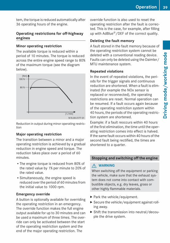
Operating restrictions for off-highwayengines
Minor operating restrictionThe available torque is reduced within aperiod of 10 minutes. The torque is reducedacross the entire engine speed range to 80%of the maximum torque (see the diagrambelow).
Reduction in output during minor operating restric-tion
Major operating restrictionThe transition between a minor and a majoroperating restriction is achieved by a gradualreduction in engine speed and torque. Thereduction takes place over a period of 60minutes.RThe engine torque is reduced from 80% of
the rated value by 1% per minute to 20% ofthe rated value.RSimultaneously, the engine speed is
reduced over the period of 60 minutes fromthe initial value to 1000 rpm.
Emergency overrideA button is optionally available for overridingthe operating restriction in an emergency.The override function makes the full engineoutput available for up to 30 minutes and canbe used a maximum of three times. The over-ride can only be activated between the startof the operating restriction system and theend of the major operating restriction. The
override function is also used to reset theoperating restriction after the fault is correc-ted. This is the case, for example, after fillingup with AdBlue®/DEF of the correct quality.
Deleting the fault memoryA fault stored in the fault memory because ofthe operating restriction system cannot bedeleted with a conventional reading device.Faults can only be deleted using the Daimler/MTU maintenance system.
Repeated violationsIn the event of repeated violations, the peri-ods for the trigger signals and continuousreduction are shortened. When a fault is elim-inated (for example the NOx sensor isreplaced or reconnected), the operatingrestrictions are reset. Normal operation canbe resumed. If a fault occurs again becauseof the operating restriction system within40 hours, the periods of the operating restric-tion system are shortened.Example: if a fault reoccurs within 40 hoursof the first elimination, the time until the oper-ating restriction comes into effect is halved.If the same fault occurs within 40 hours of thesecond fault being rectified, the times areshortened to a quarter.
Stopping and switching off the engine
G WARNINGWhen switching off the equipment or parkingthe vehicle, make sure that the exhaust sys-tem does not come into contact with com-bustible objects, e.g. dry leaves, grass orother highly flammable materials.
X Park the vehicle/equipment.X Secure the vehicle/equipment against roll-
ing away.X Shift the transmission into neutral/decou-
ple the drive system.
Operation 39
Driv
ing
mod
e/w
orki
ng m
ode
Z
Let the engine idle for approximately twominutes before switching off the engine if:Rthe coolant temperature is very high (over
90 †).Rthe engine has been operated at full output.X To switch off the engine: turn the vehicle
key in the ignition lock back to the stop atposition u.
X Press the start/stop button on the engineor on the engine shutoff device on theequipment.
X Safeguard the vehicle/equipment againstrolling away.
! Stop the engine immediately if:Rthe oil pressure falls or fluctuates signif-
icantly.Rthe power output or engine speed
decreases and the position of the posi-tion sensor (accelerator) remains con-stant.Rheavy smoke is emitted from the
exhaust.Rthe coolant or engine oil temperature
rises steeply.Rabnormal noises suddenly come from
the engine or exhaust gas turbocharger.
i When you switch off the engine, Blue-Tec® exhaust gas aftertreatment automat-ically flushes the exhaust system with freshair. Residues of AdBlue®/DEF on themetering unit or the injection nozzle mightotherwise impair the function of BlueTec®
exhaust gas aftertreatment. Depending onthe engine's previous operating load, Blue-Tec® exhaust gas aftertreatment may flushthe exhaust system several times.When BlueTec® exhaust gas aftertreatmentflushes the exhaust system, an air valve isactivated. You may then hear a hissingsound. This hissing sound does not indicatea leak in the compressed-air system.
Continuous brake
The airbrake and the constantly open throttlevalves are employed as continuous brakes.
G WARNINGDo not activate the continuous brake (enginebrake/retarder) on slippery road surfaces.The wheels may otherwise become lockedand the vehicle could skid.
You can utilise the engine's braking effect,particularly on long downhill gradients, if you:Ractivate the continuous brakeRshift to a lower gear in good time
Driving tips
Running-in
EquipmentObserve the equipment manufacturer's run-ning-in notes.
VehiclesThe running-in period of the engine has a sig-nificant effect on the vehicle, especially forthe:Rservice lifeRoperating reliabilityReconomyObserve the following notes during the run-ning-in period up to 2000 km (30 operatinghours):Ravoid subjecting the engine to full load.Rrun-in the engine with care using differing
speeds and engine revs.Ravoid high engine revs.Rdo not drive at more than ¾ of the maxi-
mum road speed for each gear.Rchange gear in good time.Rdo not shift down to brake the vehicle.Rin the case of vehicles with automatic
transmission, do not press the accelerator
40 Driving tipsDr
ivin
g m
ode/
wor
king
mod
e
pedal beyond the point of resistance (kick-down) and only engage the shift ranges 4,3, 2, or 1 when driving slowly.
After 2000 km (30 operating hours), you cangradually bring the vehicle up to full road andincreased engine speeds.
Fuel consumption
General informationFuel consumption depends on:Rthe type of fuel used (diesel fuel, fatty acid
methyl ester FAME fuel)Rthe machine versionRthe operating modeRthe operating conditionsRthe attached equipment (e.g. hydraulic
pumps, mowers, etc.)For these reasons, exact details about anysingle engine's fuel consumption cannot beprovided.
Machine versionThe following components influence fuel con-sumption:Rtyres (e.g. tyre pressure, tyre condition)Rbody typeRdrive train (e.g. transmission ratio)Radditional equipment (e.g. automatic cli-
mate control, auxiliary heating)
Operating modeYour operating mode can help to keep the fuelconsumption down:Ranticipate road and traffic conditions.Ravoid frequent acceleration and braking.Rstay within the economical engine speed
range.
Operating conditionsFuel consumption can increase due to pooroperating conditions.Observe the following notes:Ravoid driving in mountainous terrain.Rdo not allow the engine to idle when the
vehicle is stationary.Rdo not drive with unnecessary weight.Ravoid frequent cold starts.Ravoid frequent short journeys.
AdBlue® consumptionAdBlue®/DEF consumption is between 4 and8% of the fuel consumption, depending onengine use.
Engine oil consumptionAfter running in the engine, oil consumptionmay reach 0.5% of the vehicle's fuel con-sumption.More arduous operating conditions andincreased distance covered could result inengines exceeding this oil consumptionvalue.
Refuelling
Fuels
Important safety notes
G WARNINGFuel is highly flammable. Therefore, fire,naked flames and smoking are prohibitedwhen handling fuel.Deactivate the auxiliary heating when refuel-ling to prevent fuel vapours from igniting onthe auxiliary heating exhaust system.Fuel is toxic and constitutes a health hazard.Therefore, you should make sure that:
Refuelling 41
Driv
ing
mod
e/w
orki
ng m
ode
Z
Rfuel does not come into contact with skin,eyes or clothing.Ryou do not inhale fuel vapours.Rchildren are kept away from fuel.If you or anyone else comes into contact withfuel:Rwash eyes immediately with plenty of clean
water if fuel comes into contact with theeyes and consult a doctor.Rclean affected areas of skin with soap and
water immediately.Rchange out of clothing which has come into
contact with fuel immediately.Rif fuel is swallowed, a doctor should be con-
sulted immediately.
G WARNINGDo not use petrol to refuel vehicles with a die-sel engine. Do not mix diesel with petrol. Thiswould result in damage to the fuel system andengine, which could lead to a vehicle fire.
! AdBlue®/DEF is not a fuel additive andmust not be added to the diesel tank. IfAdBlue®/DEF gets into the diesel tank, thiscould lead to engine damage.
! Do not use petrol to refuel vehicles with adiesel engine. Even small amounts of petrolresult in damage to the fuel system andengine.
! If you fill the tank with the wrong fuel byaccident, do not start the engine. Other-wise, the fuel lines may be contaminated.Notify a qualified specialist workshop andhave the fuel tank and fuel lines fullydrained.
! Do not add any special fuel additives tothe diesel fuel or fatty acid methyl esterFAME fuel.Special fuel additives can lead to:RmalfunctionsRdamage to the catalytic converterRengine failure
You will find further information on fuel in the"Service products" section (Y page 50).
H Environmental noteIf fuels are handled improperly, they pose adanger to persons and the environment. Donot allow fuels to run into the sewage system,the surface waters, the ground water or intothe ground.
Before filling the tankX Switch off the engine.X Secure the vehicle/equipment against roll-
ing away.X Switch off the auxiliary heating system.X Observe the fuel grade (Y page 50).
! If you are refuelling the vehicle fromdrums or canisters, filter the fuel beforerefuelling.This prevents malfunctions in the fuel sys-tem caused by contaminated fuel.
i Regularly check the fuel prefilter with theheated water separator for condensation(Y page 86).
AdBlue®/DEF
Important safety notes
G WARNINGIf the AdBlue®/DEF tank cap is opened at hightemperatures, ammonia vapours may escape.Ammonia vapours have a pungent odour andparticularly irritate:RskinRmucous membranesReyesThe vapours may cause a burning sensationin the eyes, nose and throat as well as irrita-tion of the throat and watering eyes.Avoid inhaling ammonia vapours.
42 RefuellingDr
ivin
g m
ode/
wor
king
mod
e
G WARNINGAdBlue®/DEF must not come into contactwith skin, eyes or clothing.RIf AdBlue®/DEF comes into contact with
your eyes or skin, rinse affected areas withclean water immediately.RIf AdBlue®/DEF is swallowed, immediately
rinse your mouth out with a lot of cleanwater and drink plenty of water.RChange clothing that is soiled with
AdBlue®/DEF immediately.RIf allergic reactions occur, consult a doctor
immediately.Keep AdBlue®/DEF out of the reach of chil-dren.
! The BlueTec® exhaust gas aftertreatmentwill cease to function correctly if you:Rfill the AdBlue®/DEF reservoir with
cleaning agent or other service productsor fuelsRmix in additivesRdilute AdBlue®/DEFOnly use AdBlue®/DEF in accordance withDIN 70070/ISO 22241.Notify a qualified specialist workshop in theevent of incorrect filling.
You will find further information on AdBlue®/DEF in the "Service products" section(Y page 54).
H Environmental noteDispose of AdBlue®/DEF in an environmen-tally responsible manner.
Before filling the tankX Switch off the engine.X Secure the vehicle/equipment against roll-
ing away.X Switch off the auxiliary heating system.
Bleeding the fuel systemIf the fuel system is run dry, the system willbe bled the next time the engine is startedafter refuelling. Automatic continuous bleed-ing takes place in the filter.The battery must be sufficiently charged dur-ing the starting procedure to ensure that thefuel system can be bled.Bleed the heated fuel prefilter with water sep-arator mounted on the vehicle or equipmentusing the integrated hand pump(Y page 86).
Winter operation
Cold-start aidsThe following notes should be observed at thestart of the cold season.
Fuel
G WARNINGThere is an increased risk of fire when han-dling fuels as they are highly flammable. Avoidfire, naked flames and sparks, and refrainfrom smoking when handling fuels.
Use cold-resistant diesel fuel (Y page 50).
Jump-starting
G WARNINGThe use of liquid or gaseous starting aids cancause explosions. This may result in severeinjuries.Do not use liquid or gaseous starting aidssuch as ether or Startpilot to start the engine.
Engine oilWhen changing the oil, select an engine oilthat is compatible with the SAE classificationand the outside temperatures expected dur-ing the period of use (Y page 46).
Winter operation 43
Driv
ing
mod
e/w
orki
ng m
ode
Z
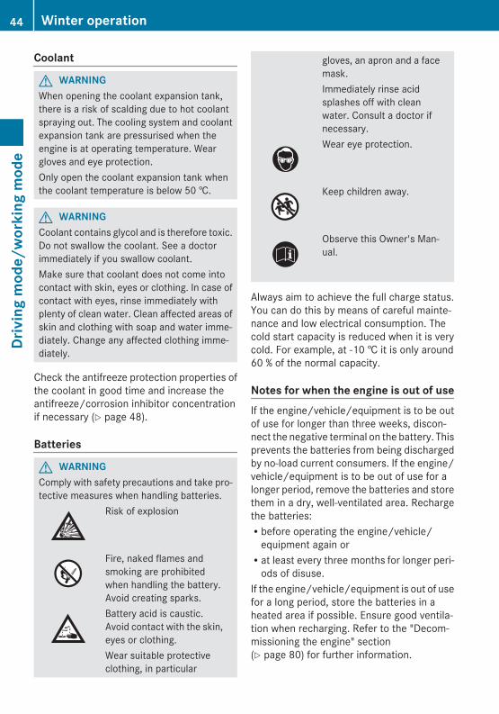
Coolant
G WARNINGWhen opening the coolant expansion tank,there is a risk of scalding due to hot coolantspraying out. The cooling system and coolantexpansion tank are pressurised when theengine is at operating temperature. Weargloves and eye protection.Only open the coolant expansion tank whenthe coolant temperature is below 50 †.
G WARNINGCoolant contains glycol and is therefore toxic.Do not swallow the coolant. See a doctorimmediately if you swallow coolant.Make sure that coolant does not come intocontact with skin, eyes or clothing. In case ofcontact with eyes, rinse immediately withplenty of clean water. Clean affected areas ofskin and clothing with soap and water imme-diately. Change any affected clothing imme-diately.
Check the antifreeze protection properties ofthe coolant in good time and increase theantifreeze/corrosion inhibitor concentrationif necessary (Y page 48).
Batteries
G WARNINGComply with safety precautions and take pro-tective measures when handling batteries.
Risk of explosion
Fire, naked flames andsmoking are prohibitedwhen handling the battery.Avoid creating sparks.Battery acid is caustic.Avoid contact with the skin,eyes or clothing.Wear suitable protectiveclothing, in particular
gloves, an apron and a facemask.Immediately rinse acidsplashes off with cleanwater. Consult a doctor ifnecessary.Wear eye protection.
Keep children away.
Observe this Owner's Man-ual.
Always aim to achieve the full charge status.You can do this by means of careful mainte-nance and low electrical consumption. Thecold start capacity is reduced when it is verycold. For example, at -10 † it is only around60 % of the normal capacity.
Notes for when the engine is out of useIf the engine/vehicle/equipment is to be outof use for longer than three weeks, discon-nect the negative terminal on the battery. Thisprevents the batteries from being dischargedby no-load current consumers. If the engine/vehicle/equipment is to be out of use for alonger period, remove the batteries and storethem in a dry, well-ventilated area. Rechargethe batteries:Rbefore operating the engine/vehicle/
equipment again orRat least every three months for longer peri-
ods of disuse.If the engine/vehicle/equipment is out of usefor a long period, store the batteries in aheated area if possible. Ensure good ventila-tion when recharging. Refer to the "Decom-missioning the engine" section(Y page 80) for further information.
44 Winter operationDr
ivin
g m
ode/
wor
king
mod
e
Service products ................................. 46Cleaning and care ............................... 55Maintenance ........................................ 56
45
Mai
nten
ance
and
car
e
Service products
Introduction to service products
G WARNINGService products are hazardous to health.They contain toxic and caustic substances.Service products are highly flammable.For this reason, observe the following instruc-tions to prevent injuries to yourself and oth-ers:RDo not inhale the vapours. When indoors,
always ensure there is sufficient ventilationto prevent intoxication.RDo not let service products come into con-
tact with skin, eyes or clothing. Should con-tact occur, however, clean the affectedareas of skin with water to prevent causticburns and other injuries.In the event of eye contact, wash eyes thor-oughly with plenty of clean water.RFire, naked flames and smoking are forbid-
den when handling service products due totheir high flammability.RObserve the usage and warning notices on
the containers.
The use of approved service products is anintegral part of the implied warranty.
! Special additives (except approved fueladditives) are neither required norapproved for use with approved serviceproducts. Additives could cause damage tothe assemblies. Therefore, do not mix anyadditives with service products.
You are responsible for the results of usingfuel additives.
H Environmental noteDispose of service products in an environ-mentally-responsible manner.
Service products are, for example:Rfuels (e.g. diesel)Rlubricants, e.g. engine and transmission
oils, hydraulic fluids, greases
Rantifreeze, coolantRAdBlue®/DEF (BlueTec® exhaust gas after-
treatment reduction agent)Approved service products fulfil the highestquality standards and are documented in theMercedes-Benz Specifications for ServiceProducts. Damage caused by the use ofservice products that have not been approvedinvalidates the implied warranty. For this rea-son, only use service products that have beenapproved for your engine.You can recognise service products approvedby Mercedes-Benz by the following inscrip-tion on the container:RMB Approval (e.g. Approval 228.5)
orRMB Approval 228.5Other labels and recommendations relatingto the quality or indicating that the productmeets a certain specification are not neces-sarily approved by Mercedes-Benz. Furtherinformation is available from any Mercedes-Benz or MTU Service Centre (Y page 11).
i Information about service products thathave been tested and approved byMercedes-Benz for your engine is availableonline at http://bevo.mercedes-benz.com/
i The specification and availability of lubri-cants may vary. Individual lubricants mayno longer be available, especially for olderengines. Information is available from anyMercedes-Benz or MTU Service Centre(Y page 11).
Engine oils
Notes on engine oilsOnly use engine oils that comply with theMercedes-Benz Specifications for ServiceProducts.
46 Service productsM
aint
enan
ce a
nd c
are
The following engine oils are approved:RSheet no. 228.5 / 228.3 standard quality
multi-grade engine oilsRSheet no. 228.51 / 228.31 low-ash multi-
grade engine oilsRSheet no. 228.2 standard quality single-
grade engine oilsRSheet no. 225.6 multi-grade engine oils,
initial operation oils
! Engine oils of a different quality grade arenot permissible and may damage theengine.
Mercedes-Benz particularly recommendsengine oils that comply with Sheet no. 228.5of the Mercedes-Benz Specifications forService Products.These engine oils are of a high standard ofquality and have a beneficial effect on:Rengine wearRfuel consumptionRexhaust emissionsThe maximum interval for oil change is onlyachieved with engine oils of a particularly highquality grade.
i You can find information on the qualitygrade, e.g. Sheet no. 228.5, and the vis-cosity, e.g. SAE class 5W-30, from the des-ignation on the oil container.
Scope of useFor engines in vehicles/equipment operatingwith diesel fuel, only use multi-grade engineoils compliant with Sheet no. 228.5 /228.51 / 228.3 / 228.31 or single-gradeengine oils compliant with Sheet no. 228.2.For engines without BlueTec® exhaust gasaftertreatment, multi-grade oils compliantwith Sheet no. 228.1 and single-grade oilscompliant with Sheet no. 228.0 can also beused.For vehicle/equipment operation with FAMEfatty acid methyl ester fuel (bio-diesel fuel),
only use engine oils compliant with Sheet no.228.5 / 228.51 / 228.3 / 228.31.For engines without BlueTec® exhaust gasaftertreatment, oils compliant with Sheet no.228.1 can also be used. This is also requiredfor a mixture of conventional diesel fuels andFAME fatty acid methyl ester fuels (bio-dieselfuel).Multi-grade engine oils compliant with Sheetno. 228.5 / 228.51 / 228.3 / 228.31 / 228.1can be used throughout the year. Dependingon the fuel quality (fuel sulphur content orFAME fatty acid methyl ester fuel), the oilchange intervals may be shortened. Fordetails, see the Maintenance Booklet.Single-grade engine oils compliant with Sheetno. 228.2 / 228.0 only cover an SAE class(viscosity) for a certain temperature range.Change the engine oil to an SAE class suitablefor the time of year and the respective outsidetemperatures.The use of low-ash engine oils is permissiblebut not essential. When low-ash engine oilscompliant with Sheet no. 228.51 and 228.31are used, a low-sulphur diesel fuel (less than50 ppm, 0.005 % by weight) should be used.If this low-sulphur diesel fuel is not available,standard oils compliant with Sheet no.228.5 / 228.3 / 228.2 should be used.
Oil changeOil change intervals are dependent on the fol-lowing:Rthe operating conditions of the vehicleRthe grade of the engine oil usedRthe fuel grade (sulphur content)Rthe fuel type, e.g. FAME fatty acid methyl
ester fuelFor more details, see the Maintenance Book-let.
! If you do not use oil for all-year-roundoperation in your engine, change theengine oil right at the beginning of the coldseason. Use only an approved engine oil inthe specified SAE classification.
Service products 47
Mai
nten
ance
and
car
e
Z
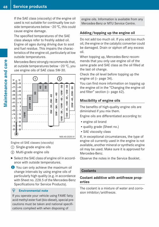
If the SAE class (viscosity) of the engine oilused is not suitable for continually low out-side temperatures below −20 †, this couldcause engine damage.The specified temperatures of the SAEclass always refer to freshly added oil.Engine oil ages during driving due to sootand fuel residue. This impairs the charac-teristics of the engine oil, particularly at lowoutside temperatures.Mercedes-Benz strongly recommends that,at outside temperatures below −20 †, youuse engine oils of SAE class 5W-30.
Engine oil SAE classes (viscosity): Single-grade engine oils; Multi-grade engine oilsX Select the SAE class of engine oil in accord-
ance with outside temperatures.i You can only achieve the maximum oil
change intervals by using engine oils ofparticularly high quality (e.g. in accordancewith Sheet no. 228.5 of the Mercedes-BenzSpecifications for Service Products).
H Environmental noteIf you operate your vehicle using FAME fattyacid methyl ester fuel (bio-diesel), special pre-cautions must be taken and national specifi-cations complied with when disposing of
engine oils. Information is available from anyMercedes-Benz or MTU Service Centre.
Adding/topping up the engine oilDo not add too much oil. If you add too muchoil, the engine or the catalytic converter couldbe damaged. Drain or siphon off any excessoil.When topping up, Mercedes-Benz recom-mends that you only use engine oil of thesame grade and SAE class as the oil filled atthe last oil change.Check the oil level before topping up theengine oil (Y page 34).You can find more information on topping upthe engine oil in the “Changing the engine oiland filter” section (Y page 62).
Miscibility of engine oilsThe benefits of high-quality engine oils arediminished if you mix them.Engine oils are differentiated according to:Rengine oil brandRquality grade (Sheet no.)RSAE viscosity classIf, in exceptional circumstances, the type ofengine oil currently used in the engine is notavailable, another mineral or synthetic engineoil may be used. Make sure it is approved forMercedes-Benz.Observe the notes in the Service Booklet.
Coolants
Coolant additive with antifreeze prop-ertiesThe coolant is a mixture of water and corro-sion inhibitor/antifreeze.
48 Service productsM
aint
enan
ce a
nd c
are
The corrosion inhibitor/antifreeze in the cool-ant has the following properties:Ranti-corrosion protectionRantifreeze protectionRincreases the boiling temperatureLeave the coolant in the engine all year roundin order to prevent corrosion and to increasethe boiling point. Also do this in countries withhot outside temperatures.Check the corrosion inhibitor/antifreeze con-centration in the coolant every six months.Only use approved corrosion inhibitor/anti-freeze agents.
Topping up coolantWhen topping up, only use prepared coolantwith 50% by volume corrosion inhibitor/anti-freeze agent.Before topping up, observe the quality of thecorrosion inhibitor/antifreeze agent in thecooling system (Sheet no.). Corrosion inhibi-tors/antifreeze agents compliant with Sheet325.3 and 326.3 must not be mixed withthose of Sheet 325.0/2 or 326.0/2.Only top up using a corrosion inhibitor/anti-freeze agent of the same quality grade.
Miscibility of corrosion inhibitor/anti-freeze agents! Corrosion inhibitors/antifreeze agents
that comply with Sheet 325.3 and 326.3must not be mixed with those of Sheet325.0/2 or 326.0/2. This prevents dam-age to the engine cooling system.
Renewing coolantCoolant change with antifreeze protection:Revery three years if using corrosion inhibi-
tor/antifreeze agent compliant with Sheet325.0/2 and 326.0/2Revery five years if using corrosion inhibitor/
antifreeze agent compliant with Sheet325.3 and 326.3
Coolant change with corrosion inhibitor/anti-freeze agent compliant with Sheet 325.3,326.3: before adding this corrosion inhibitor/
antifreeze agent, the cooling system mustfirst be flushed (Y page 76).When renewing the coolant, ensure that itcontains 50% by volume of corrosion inhibi-tor/antifreeze agent. This corresponds toantifreeze protection down to −37 †.Do not exceed 55% by volume (antifreeze pro-tection down to approximately −45 †). Heatdissipation properties are otherwiseimpaired.The water in the coolant must meet certainrequirements, which are often fulfilled bydrinking water. The water must be treated ifits quality does not meet the required stand-ards.Please note the Mercedes-Benz Specifica-tions for Service Products, Sheet num-ber 310.1.Further information about operating and roadsafety for your engine/vehicle/equipment isavailable from any Mercedes-Benz or MTUService Centre (Y page 11).
Coolant additive without antifreeze prop-ertiesIf your vehicle does not need antifreeze pro-tection, e.g. in countries with consistentlyhigh outside temperatures, you can, as anexception, use a coolant additive.Instead of corrosion inhibitor/antifreezeadditive, add a coolant additive compliantwith Sheet number 312.0 of the Mercedes-Benz Specifications for Service Products tothe water.Improvers (corrosion-inhibiting oils) are notpermitted.Renew the coolant annually.Further information about the required waterquality and approved coolant additives with-out antifreeze protection is available from anyMercedes-Benz or MTU Service Centre(Y page 11).
Service products 49
Mai
nten
ance
and
car
e
Z
Diesel fuels
Important safety notes
G WARNINGFuel is highly flammable. Fire, naked flamesand smoking as well as the use of auxiliaryheaters (sparks) are therefore prohibitedwhen handling fuel.Switch off the engine and the auxiliary heatingbefore refueling.
G WARNINGAvoid contact with fuels.It is hazardous to your health if your skincomes into direct contact with fuels or youbreathe in fuel vapours.
! If you are using drums or canisters torefuel the engine/vehicle/equipment, youshould filter the fuel before filling.This prevents malfunctions in the fuel sys-tem caused by contaminated fuel.
! Only refuel with commercially availablediesel vehicle fuel that complies with theEuropean standard EN 590.EN 590 describes a sulphur-free fuel with amaximum sulphur content of 10 ppm. How-ever, it is also permitted to operate engineswith BlueTec® exhaust gas aftertreatmentwith up to 50 ppm.For engines without BlueTec® exhaust gasaftertreatment, the maintenance intervalsmust be reduced when operating withhigher sulphur contents. For details on this,see the table below. Even if the mainte-nance intervals are reduced, operation withhigher sulphur contents will lead toincreased engine wear, especially on thefuel injectors.When necessary, use only approved fueladditives.There is otherwise a risk of impaired engineperformance or engine and catalytic con-verter damage. The use of appropriate fueladditives is your responsibility.
! Fuel grade in accordance with EN 590 isprescribed as mandatory for engines withBlueTec® exhaust gas aftertreatment. Ifdiesel fuel which does not comply with EN590 is used, it can damage the exhaustsystem.
Fuel gradeThe following is an overview of typical sulphurcontent in percent by weight of fuel availablein various countries. You may obtain informa-tion about current country-specific fuel sul-phur contents from any Mercedes-Benz orMTU Service Centre (Y page 11).
i In some countries, diesel fuel of differingsulphur contents is available. Diesel fuelwith a lower sulphur content is sold underthe name "Euro diesel" in some countries.
50 Service productsM
aint
enan
ce a
nd c
are
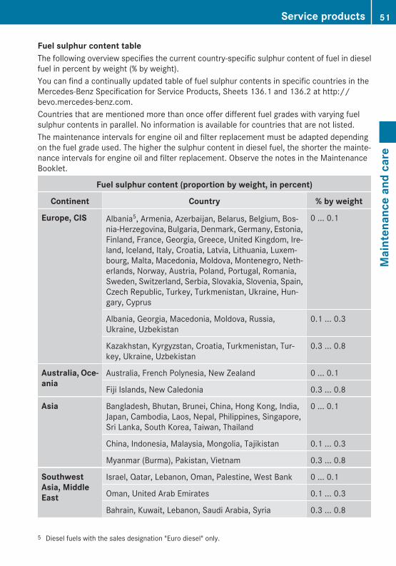
Fuel sulphur content tableThe following overview specifies the current country-specific sulphur content of fuel in dieselfuel in percent by weight (% by weight).You can find a continually updated table of fuel sulphur contents in specific countries in theMercedes-Benz Specification for Service Products, Sheets 136.1 and 136.2 at http://bevo.mercedes-benz.com.Countries that are mentioned more than once offer different fuel grades with varying fuelsulphur contents in parallel. No information is available for countries that are not listed.The maintenance intervals for engine oil and filter replacement must be adapted dependingon the fuel grade used. The higher the sulphur content in diesel fuel, the shorter the mainte-nance intervals for engine oil and filter replacement. Observe the notes in the MaintenanceBooklet.
Fuel sulphur content (proportion by weight, in percent)
Continent Country % by weight
Europe, CIS Albania5, Armenia, Azerbaijan, Belarus, Belgium, Bos-nia-Herzegovina, Bulgaria, Denmark, Germany, Estonia,Finland, France, Georgia, Greece, United Kingdom, Ire-land, Iceland, Italy, Croatia, Latvia, Lithuania, Luxem-bourg, Malta, Macedonia, Moldova, Montenegro, Neth-erlands, Norway, Austria, Poland, Portugal, Romania,Sweden, Switzerland, Serbia, Slovakia, Slovenia, Spain,Czech Republic, Turkey, Turkmenistan, Ukraine, Hun-gary, Cyprus
0 ... 0.1
Albania, Georgia, Macedonia, Moldova, Russia,Ukraine, Uzbekistan
0.1 ... 0.3
Kazakhstan, Kyrgyzstan, Croatia, Turkmenistan, Tur-key, Ukraine, Uzbekistan
0.3 ... 0.8
Australia, Oce-ania
Australia, French Polynesia, New Zealand 0 ... 0.1
Fiji Islands, New Caledonia 0.3 ... 0.8
Asia Bangladesh, Bhutan, Brunei, China, Hong Kong, India,Japan, Cambodia, Laos, Nepal, Philippines, Singapore,Sri Lanka, South Korea, Taiwan, Thailand
0 ... 0.1
China, Indonesia, Malaysia, Mongolia, Tajikistan 0.1 ... 0.3
Myanmar (Burma), Pakistan, Vietnam 0.3 ... 0.8
Southwest Asia, Middle East
Israel, Qatar, Lebanon, Oman, Palestine, West Bank 0 ... 0.1
Oman, United Arab Emirates 0.1 ... 0.3
Bahrain, Kuwait, Lebanon, Saudi Arabia, Syria 0.3 ... 0.8
5 Diesel fuels with the sales designation "Euro diesel" only.
Service products 51
Mai
nten
ance
and
car
e
Z
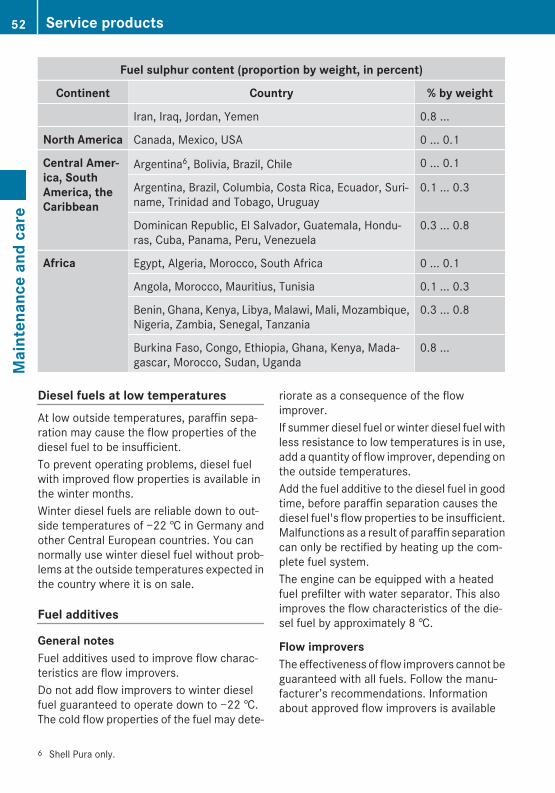
Fuel sulphur content (proportion by weight, in percent)
Continent Country % by weight
Iran, Iraq, Jordan, Yemen 0.8 ...
North America Canada, Mexico, USA 0 ... 0.1
Central Amer-ica, South America, the Caribbean
Argentina6, Bolivia, Brazil, Chile 0 ... 0.1
Argentina, Brazil, Columbia, Costa Rica, Ecuador, Suri-name, Trinidad and Tobago, Uruguay
0.1 ... 0.3
Dominican Republic, El Salvador, Guatemala, Hondu-ras, Cuba, Panama, Peru, Venezuela
0.3 ... 0.8
Africa Egypt, Algeria, Morocco, South Africa 0 ... 0.1
Angola, Morocco, Mauritius, Tunisia 0.1 ... 0.3
Benin, Ghana, Kenya, Libya, Malawi, Mali, Mozambique,Nigeria, Zambia, Senegal, Tanzania
0.3 ... 0.8
Burkina Faso, Congo, Ethiopia, Ghana, Kenya, Mada-gascar, Morocco, Sudan, Uganda
0.8 ...
Diesel fuels at low temperaturesAt low outside temperatures, paraffin sepa-ration may cause the flow properties of thediesel fuel to be insufficient.To prevent operating problems, diesel fuelwith improved flow properties is available inthe winter months.Winter diesel fuels are reliable down to out-side temperatures of −22 † in Germany andother Central European countries. You cannormally use winter diesel fuel without prob-lems at the outside temperatures expected inthe country where it is on sale.
Fuel additives
General notesFuel additives used to improve flow charac-teristics are flow improvers.Do not add flow improvers to winter dieselfuel guaranteed to operate down to −22 †.The cold flow properties of the fuel may dete-
riorate as a consequence of the flowimprover.If summer diesel fuel or winter diesel fuel withless resistance to low temperatures is in use,add a quantity of flow improver, depending onthe outside temperatures.Add the fuel additive to the diesel fuel in goodtime, before paraffin separation causes thediesel fuel's flow properties to be insufficient.Malfunctions as a result of paraffin separationcan only be rectified by heating up the com-plete fuel system.The engine can be equipped with a heatedfuel prefilter with water separator. This alsoimproves the flow characteristics of the die-sel fuel by approximately 8 †.
Flow improversThe effectiveness of flow improvers cannot beguaranteed with all fuels. Follow the manu-facturer’s recommendations. Informationabout approved flow improvers is available
6 Shell Pura only.
52 Service productsM
aint
enan
ce a
nd c
are
from all Mercedes-Benz or MTU Service Cen-tres (Y page 11).If you add a flow improver to the FAME fattyacid methyl ester fuel, the fuel's resistance tolow temperatures does not change.
Fatty acid methyl ester (FAME) fuel(bio-diesel)
General notes! To avoid damage to the assemblies and
components, observe the following pointswhen using FAME fatty acid methyl esterfuel:Rhave the fuel filter and the oil filter
replaced approximately 1000 km afterswitching to FAME fatty acid methylester fuel.Rhave the oil filter and the fuel filter
replaced at every oil change.Rthe oil will have to be changed and the oil
filter replaced much more frequently.RFAME fatty acid methyl ester fuel short-
ens the service life of conventional fuelfilters. For this reason, Mercedes-Benzrecommends the installation of a specialfuel prefilter. Information about this isavailable at any qualified specialist work-shop, e.g. a Mercedes-Benz or MTUService Centre.Ronly add FAME fatty acid methyl ester
fuel in compliance with DIN EN 14214.Fuel additives or fuels that do not complywith DIN EN 14214 may cause malfunc-tions or engine damage.RFAME fatty acid methyl ester fuel cor-
rodes painted surfaces. Do not allowFAME fatty acid methyl ester fuel tocome into contact with the paintwork.Rinse off FAME fatty acid methyl esterfuel with water immediately.Rpreferably only add engine oil in accord-
ance with Sheet no. 228.5/51 or228.3/31 of the Mercedes-Benz Speci-fications for Service Products.
Rif the vehicle is not used for long periodsof time, FAME fatty acid methyl ester fuelcan clog fuel system components. Forthis reason, use all the FAME fatty acidmethyl ester fuel before long periods oftime when the vehicle is not used. Fill upthe fuel tank with conventional dieselfuel. Allow the engine to run for at leastone hour before switching off the vehi-cle/equipment.RMercedes Benz recommends that you do
not use FAME fatty acid methyl ester fuelfor engines that are not used for longperiods of time, e.g. fire engines.Rthe auxiliary heating may only be oper-
ated with conventional diesel fuel. Oth-erwise, the system may malfunction.Conventional diesel fuel already containsa percentage of FAME fatty acid methylester fuel. Therefore, do not add morethan 5% FAME fatty acid methyl ester fuelto conventional diesel fuel.An additional fuel tank is required forconventional diesel fuel for the auxiliaryheating system, if you operate the vehi-cle:- using FAME fatty acid methyl ester fuel- using a mixture of conventional diesel
fuel and more than 5% FAME fatty acidmethyl ester fuel.
H Environmental noteIf the vehicle runs on FAME fatty acid methylester fuel, ask your disposal plant whetheryou have to collect the engine oil separately.Not all manufacturers of refined products(lubricant manufactured from used engine oil)can process engine oil which has beenenriched with FAME fatty acid methyl esterfuel.Observe the special notes and national regu-lations when disposing of engine oils. Infor-mation about this is available at any qualifiedspecialist workshop, e.g. any Mercedes-Benzor MTU Service Centre.
Service products 53
Mai
nten
ance
and
car
e
Z
Operate your engine using pure FAME fattyacid methyl ester fuel compliant withDIN EN 14214. You can also operate yourengine using a mixture of conventional dieselfuel and FAME fatty acid methyl ester fuel.This also applies to engines with BlueTec®
exhaust gas aftertreatment.Observe the specifications in accordancewith Sheet no. 135.0 of the Mercedes-BenzSpecifications for Service Products for oper-ation with FAME fatty acid methyl ester fuel.Operating the vehicle with FAME fatty acidmethyl ester fuel results in:Ra slightly higher fuel consumptionRa slightly reduced engine power outputRincreased white smoke after a cold start
Low outside temperaturesFAME fatty acid methyl ester fuel compliantwith DIN EN 14214 can be used reliably atoutside temperatures down to −20 †.For lower temperatures, the engine can beequipped with a fuel preheating system. Thisimproves the flow characteristics of the FAMEfatty acid methyl ester fuel according to theheat output installed.
AdBlue®/DEF
Notes on AdBlue®/DEFAdBlue®/DEF is a non-flammable, non-toxic,colourless, odourless and water-soluble liq-uid.The terms "Urea" and "DEF" (Diesel ExhaustFluid) are also used for "AdBlue®".
! Only use AdBlue®/DEF in accordancewith DIN 70070/ISO 22241. Do not useany additives.If AdBlue®/DEF comes into contact withpainted or aluminium surfaces when fillingthe tank, rinse the affected area immedi-ately with plenty of water.
High outside temperatures
G WARNINGIf the AdBlue®/DEF tank cap is opened at hightemperatures, ammonia vapours may escape.Ammonia vapours have a pungent odour andparticularly irritate:RskinRmucous membranesReyesThe vapours may cause a burning sensationin the eyes, nose and throat as well as irrita-tion of the throat and watering eyes.Avoid inhaling ammonia vapours.
G WARNINGAdBlue®/DEF must not come into contactwith skin, eyes or clothing.RIf AdBlue®/DEF comes into contact with
your eyes or skin, rinse affected areas withclean water immediately.RIf AdBlue®/DEF is swallowed, immediately
rinse your mouth out with a lot of cleanwater and drink plenty of water.RChange clothing that is soiled with
AdBlue®/DEF immediately.RIf allergic reactions occur, consult a doctor
immediately.Keep AdBlue®/DEF out of the reach of chil-dren.
The chemical composition of AdBlue®/DEFcan break down if it heats up to 50 † over along period (e.g. as a result of direct sunlighton the tank). This creates ammonia vapour.
Low outside temperaturesAdBlue®/DEF freezes at a temperature ofapproximately −11 †. Winter operation isalso ensured for temperatures below −11 †.At low temperatures, AdBlue®/DEF crystalsmay form on the coiled hose between theengine and the silencer. This crystallisationdoes not pose a risk to the correct operation
54 Service productsM
aint
enan
ce a
nd c
are
of BlueTec® exhaust gas aftertreatment. TheAdBlue®/DEF crystals can be removed withclean water if necessary.
Additives, tap water! Do not mix additives to AdBlue®/DEF. Do
not dilute AdBlue®/DEF with tap water.This could destroy the BlueTec® exhaustgas aftertreatment system.
StorageOnly use containers made of the followingmaterials to store AdBlue®/DEF:RCr-Ni steels in accordance with
DIN EN 10 088-1/2/3RMo-Cr-Ni steels in accordance with
DIN EN 10 088-1/2/3RPolypropyleneRPolyethylene
! Containers made of the following materi-als are not suitable for the storage ofAdBlue®/DEF:RaluminiumRcopperRcopper alloysRunalloyed steelRgalvanised steelIf AdBlue® is stored in these types of con-tainer, constituents of these metals maydissolve and damage the BlueTec® exhaustgas aftertreatment beyond repair.
Disposal
H Environmental noteDispose of AdBlue®/DEF in an environmen-tally responsible manner.
Observe laws and regulations on the disposalof AdBlue®/DEF in the country concerned.
Purity! Impurities in AdBlue®/DEF, e.g. due to
other service products, cleaning productsor dust, may lead to:Rincreased emission valuesRdamage to the catalytic converterRengine damageRmalfunctions in BlueTec® exhaust gas
aftertreatment.
Ensure that AdBlue®/DEF is always pure toavoid malfunctions in BlueTec® exhaust gasaftertreatment.If AdBlue®/DEF is pumped from the tank, e.g.during repairs, do not use this fluid to refill thetank. Otherwise the purity of the fluid wouldno longer be guaranteed.
Cleaning and care
Notes on care
G WARNINGAlways keep care products sealed and out ofthe reach of children. Always follow theinstructions for the use of the care products.Do not use fuel as a cleaning agent. Fuels arehighly flammable and constitute a health haz-ard.
Regular care helps to maintain the value ofthe engine.Mercedes-Benz recommends that you onlyuse care products that have been approvedfor Mercedes-Benz. You can obtain thesecare products from any Mercedes-Benz orMTU Service Centre (Y page 11).
High-pressure cleaning! The exhaust gas aftertreatment system
may only be cleaned when it is cool. Thesensors can otherwise be damaged.
Cleaning and care 55
Mai
nten
ance
and
car
e
Z
! When cleaning, never point the water jetat the exhaust pipe. The system may oth-erwise be damaged.
! When using a high-pressure cleaner, keepa minimum distance between the high-pressure nozzle and the engine parts. Oth-erwise, parts of the engine may be dam-aged.Observe the following minimum distances:Rabout 70 cm with round-spray jetsRabout 30 cm with 25° flat-spray jetsRabout 30 cm with concentrated-power
jets
! Keep the water jet moving constantlywhile cleaning. In this way, you will avoidcausing damage.Do not point the water jet at:Relectrical componentsRplug connectorsRsealsRhoses
Cleaning the engine! Observe the following notes when clean-
ing the engine. This avoids malfunctionsand damage to the engine.RWhen using high-pressure or steam
cleaners, do not point the spray directlyat electrical components and electriccables.RMake sure that no water enters the air
intake and ventilation openings.RTreat the engine with preservative
agents after it has been cleaned. Whendoing so, protect the belt drive systemfrom the preservative agent.RUse only wax preservative for engines
according to sheet number 385.4 of theMercedes-Benz Specifications forService Products.
Maintenance
General information
G WARNINGBefore carrying out maintenance or repairwork, you must read the relevant sections ofthe technical documentation relating to main-tenance and repair measures, e.g. the Oper-ating Instructions and workshop information.In particular, first familiarise yourself with thelegal regulations, e.g. work safety and acci-dent prevention regulations.You could otherwise fail to recognise dangersand injure yourself or others.Always have maintenance work carried out ata qualified specialist workshop which has thenecessary specialist knowledge and tools tocarry out the work required.Mercedes-Benz recommends that you use aMercedes-Benz or MTU Service Centre forthis purpose. All work relevant to safety or onsafety-related systems must be carried out ata qualified specialist workshop.
G WARNINGMaintenance work that is carried out incor-rectly or not at all, e.g. not changing the oilfilter or not observing maintenance intervals,can cause engine damage. Engine damagecan lead to an increased risk of accidents.Therefore, observe the notes on engine main-tenance in these Operating Instructions.
H Environmental noteIf circumstances demand that you have to dosome maintenance work yourself, environ-mental protection requirements must beobserved. When disposing of service prod-ucts, e.g. engine oil, you must comply with thelegal requirements. This also applies to allparts, e.g. filters, that have been in contactwith service products. For vehicles run onFAME (fatty acid methyl ester) fuel, the spe-cial instructions on disposing of engine oilmust be observed. For more information, visita qualified specialist workshop, e.g. a
56 MaintenanceM
aint
enan
ce a
nd c
are
Mercedes-Benz or MTU Service Centre. Dis-pose of empty containers, cleaning cloths andcare products in an environmentally respon-sible manner. Observe the instructions forcare products. Do not let the engine run lon-ger than necessary when stationary.
i All maintenance work and maintenanceintervals refer to genuine Mercedes-Benzparts and accessories that have beenexpressly approved for the engine byMercedes Benz.
The scope of maintenance and frequency ofmaintenance work depend on the differentoperating conditions and are listed in theMaintenance Booklet.Have any work that is carried out confirmedwith an entry in the Maintenance Booklet.This proof of regular maintenance is alwaysrequired for any warranty claims.Please also observe the maintenance instruc-tions for special accessories.
Maintenance 57
Mai
nten
ance
and
car
e
Z

58

Work schedule overview .................... 60Work schedules .................................. 62
59
Note
s on
mai
nten
ance
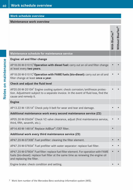
Work schedule overview
Maintenance work overview
With
Blu
eTec
®
With
out B
lueT
ec®
Maintenance schedule for maintenance service
Engine: oil and filter change
AP18.00-W-0101C7Operation with diesel fuel: carry out an oil and filter changeat least every two years.
• •
AP18.00-W-0101C7Operation with FAME fuels (bio-diesel): carry out an oil andfilter change at least once a year.
• •
Check and adjust the fluid level
AP20.00-W-2010A7 Engine cooling system: check corrosion/antifreeze protec-tion. Adjustment subject to a separate invoice. In the event of fluid loss, find thecause and remedy it.
• •
Engine
AP13.22-W-1351A7 Check poly-V-belt for wear and tear and damage. • •
Additional maintenance work every second maintenance service (Z2)
AP05.30-W-0560A7 Check V2 valve clearance, adjust (first maintenance service,third, fifth, seventh, etc.).
• •
AP14.40-W-1481A7 Replace AdBlue®/DEF filter. •
Additional work every third maintenance service (Z3)
AP47.20-W-0730B7 Fuel prefilter: cleaning the filter element. • •
AP47.20-W-0783A7 Fuel prefilter with water separator: replace fuel filter. • •
AP47.20-W-0780A7 Fuel filter: replace fuel filter element. For operation with FAMEfuels (bio-diesel): replace fuel filter at the same time as renewing the engine oiland replacing the filter.
• •
Engine brake: check condition and setting. • •
7 Work item number of the Mercedes-Benz workshop information system (WIS).
60 Work schedule overviewNo
tes
on m
aint
enan
ce
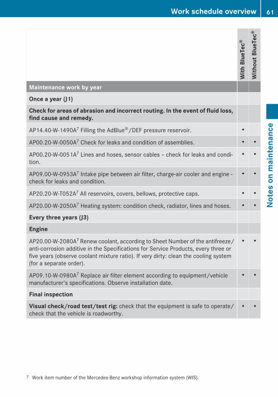
With
Blu
eTec
®
With
out B
lueT
ec®
Maintenance work by year
Once a year (J1)
Check for areas of abrasion and incorrect routing. In the event of fluid loss, find cause and remedy.
AP14.40-W-1490A7 Filling the AdBlue®/DEF pressure reservoir. •
AP00.20-W-0050A7 Check for leaks and condition of assemblies. • •
AP00.20-W-0051A7 Lines and hoses, sensor cables – check for leaks and condi-tion.
• •
AP09.00-W-0953A7 Intake pipe between air filter, charge-air cooler and engine -check for leaks and condition.
• •
AP20.20-W-T052A7 All reservoirs, covers, bellows, protective caps. • •
AP20.00-W-2050A7 Heating system: condition check, radiator, lines and hoses. • •
Every three years (J3)
Engine
AP20.00-W-2080A7 Renew coolant, according to Sheet Number of the antifreeze/anti-corrosion additive in the Specifications for Service Products, every three orfive years (observe coolant mixture ratio). If very dirty: clean the cooling system(for a separate order).
• •
AP09.10-W-0980A7 Replace air filter element according to equipment/vehiclemanufacturer's specifications. Observe installation date.
• •
Final inspection
Visual check/road test/test rig: check that the equipment is safe to operate/check that the vehicle is roadworthy.
• •
7 Work item number of the Mercedes-Benz workshop information system (WIS).
Work schedule overview 61
Note
s on
mai
nten
ance
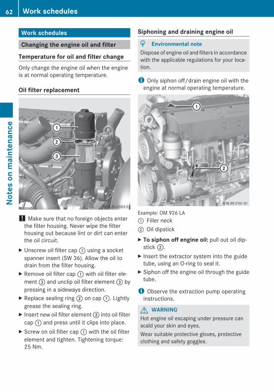
Work schedules
Changing the engine oil and filter
Temperature for oil and filter changeOnly change the engine oil when the engineis at normal operating temperature.
Oil filter replacement
! Make sure that no foreign objects enterthe filter housing. Never wipe the filterhousing out because lint or dirt can enterthe oil circuit.
X Unscrew oil filter cap : using a socketspanner insert (SW 36). Allow the oil todrain from the filter housing.
X Remove oil filter cap : with oil filter ele-ment = and unclip oil filter element = bypressing in a sideways direction.
X Replace sealing ring ; on cap :. Lightlygrease the sealing ring.
X Insert new oil filter element = into oil filtercap : and press until it clips into place.
X Screw on oil filter cap : with the oil filterelement and tighten. Tightening torque:25 Nm.
Siphoning and draining engine oil
H Environmental noteDispose of engine oil and filters in accordancewith the applicable regulations for your loca-tion.
i Only siphon off/drain engine oil with theengine at normal operating temperature.
Example: OM 926 LA: Filler neck; Oil dipstickX To siphon off engine oil: pull out oil dip-
stick ;.X Insert the extractor system into the guide
tube, using an O-ring to seal it.X Siphon off the engine oil through the guide
tube.
i Observe the extraction pump operatinginstructions.
G WARNINGHot engine oil escaping under pressure canscald your skin and eyes.Wear suitable protective gloves, protectiveclothing and safety goggles.
62 Work schedulesNo
tes
on m
aint
enan
ce
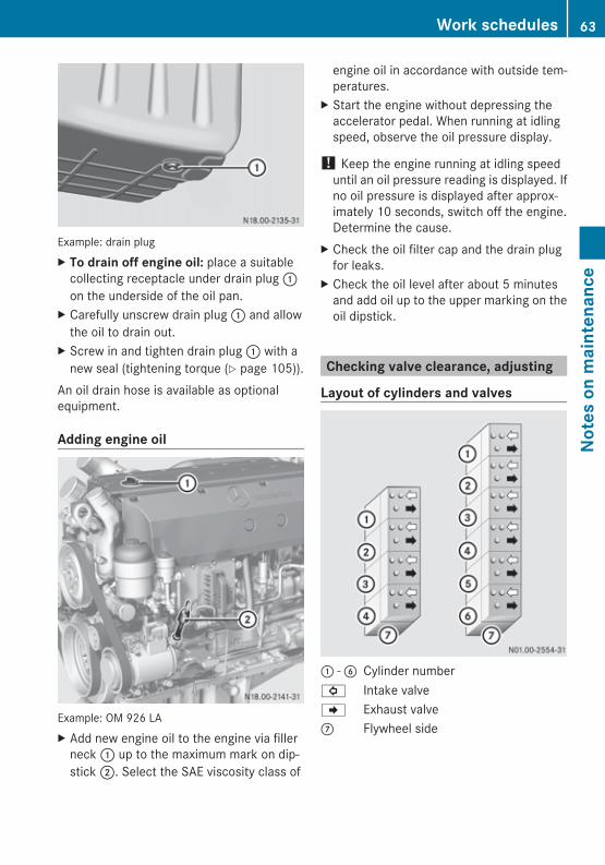
Example: drain plugX To drain off engine oil: place a suitable
collecting receptacle under drain plug :on the underside of the oil pan.
X Carefully unscrew drain plug : and allowthe oil to drain out.
X Screw in and tighten drain plug : with anew seal (tightening torque (Y page 105)).
An oil drain hose is available as optionalequipment.
Adding engine oil
Example: OM 926 LAX Add new engine oil to the engine via filler
neck : up to the maximum mark on dip-stick ;. Select the SAE viscosity class of
engine oil in accordance with outside tem-peratures.
X Start the engine without depressing theaccelerator pedal. When running at idlingspeed, observe the oil pressure display.
! Keep the engine running at idling speeduntil an oil pressure reading is displayed. Ifno oil pressure is displayed after approx-imately 10 seconds, switch off the engine.Determine the cause.
X Check the oil filter cap and the drain plugfor leaks.
X Check the oil level after about 5 minutesand add oil up to the upper marking on theoil dipstick.
Checking valve clearance, adjusting
Layout of cylinders and valves
: - B Cylinder number# Intake valveJ Exhaust valveC Flywheel side
Work schedules 63
Note
s on
mai
nten
ance
Z
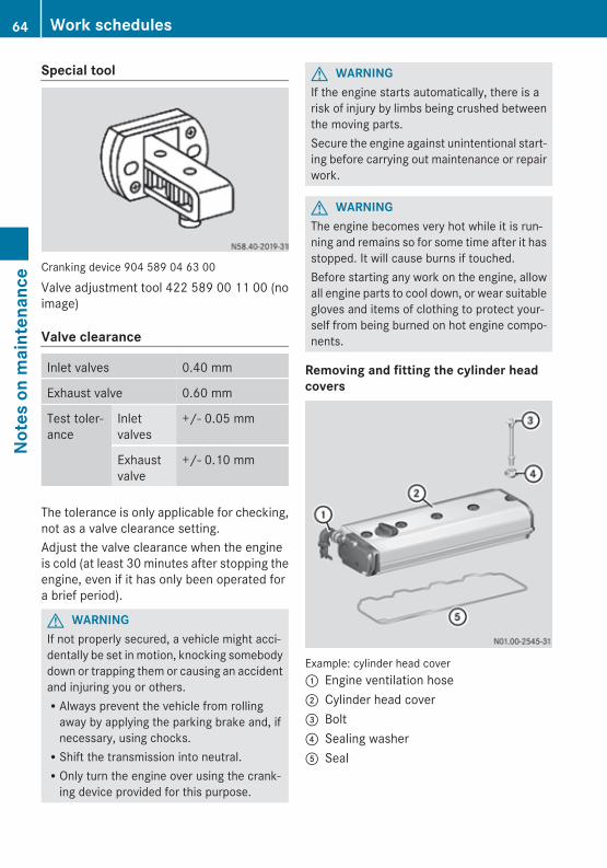
Special tool
Cranking device 904 589 04 63 00
Valve adjustment tool 422 589 00 11 00 (noimage)
Valve clearance
Inlet valves 0.40 mm
Exhaust valve 0.60 mm
Test toler-ance
Inletvalves
+/- 0.05 mm
Exhaustvalve
+/- 0.10 mm
The tolerance is only applicable for checking,not as a valve clearance setting.Adjust the valve clearance when the engineis cold (at least 30 minutes after stopping theengine, even if it has only been operated fora brief period).
G WARNINGIf not properly secured, a vehicle might acci-dentally be set in motion, knocking somebodydown or trapping them or causing an accidentand injuring you or others.RAlways prevent the vehicle from rolling
away by applying the parking brake and, ifnecessary, using chocks.RShift the transmission into neutral.ROnly turn the engine over using the crank-
ing device provided for this purpose.
G WARNINGIf the engine starts automatically, there is arisk of injury by limbs being crushed betweenthe moving parts.Secure the engine against unintentional start-ing before carrying out maintenance or repairwork.
G WARNINGThe engine becomes very hot while it is run-ning and remains so for some time after it hasstopped. It will cause burns if touched.Before starting any work on the engine, allowall engine parts to cool down, or wear suitablegloves and items of clothing to protect your-self from being burned on hot engine compo-nents.
Removing and fitting the cylinder headcovers
Example: cylinder head cover: Engine ventilation hose; Cylinder head cover= Bolt? Sealing washerA Seal
64 Work schedulesNo
tes
on m
aint
enan
ce
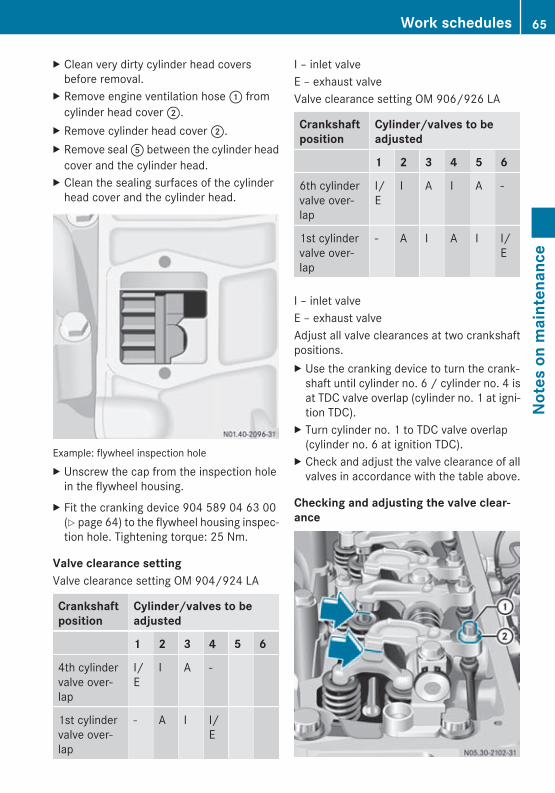
X Clean very dirty cylinder head coversbefore removal.
X Remove engine ventilation hose : fromcylinder head cover ;.
X Remove cylinder head cover ;.X Remove seal A between the cylinder head
cover and the cylinder head.X Clean the sealing surfaces of the cylinder
head cover and the cylinder head.
Example: flywheel inspection holeX Unscrew the cap from the inspection hole
in the flywheel housing.X Fit the cranking device 904 589 04 63 00
(Y page 64) to the flywheel housing inspec-tion hole. Tightening torque: 25 Nm.
Valve clearance settingValve clearance setting OM 904/924 LA
Crankshaftposition
Cylinder/valves to beadjusted
1 2 3 4 5 6
4th cylindervalve over-lap
I/E
I A -
1st cylindervalve over-lap
- A I I/E
I – inlet valveE – exhaust valveValve clearance setting OM 906/926 LA
Crankshaftposition
Cylinder/valves to beadjusted
1 2 3 4 5 6
6th cylindervalve over-lap
I/E
I A I A -
1st cylindervalve over-lap
- A I A I I/E
I – inlet valveE – exhaust valveAdjust all valve clearances at two crankshaftpositions.X Use the cranking device to turn the crank-
shaft until cylinder no. 6 / cylinder no. 4 isat TDC valve overlap (cylinder no. 1 at igni-tion TDC).
X Turn cylinder no. 1 to TDC valve overlap(cylinder no. 6 at ignition TDC).
X Check and adjust the valve clearance of allvalves in accordance with the table above.
Checking and adjusting the valve clear-ance
Work schedules 65
Note
s on
mai
nten
ance
Z
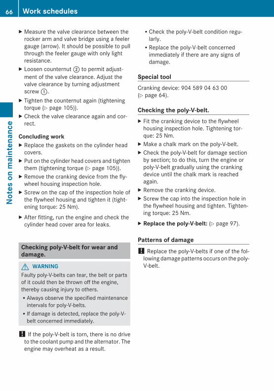
X Measure the valve clearance between therocker arm and valve bridge using a feelergauge (arrow). It should be possible to pullthrough the feeler gauge with only lightresistance.
X Loosen counternut ; to permit adjust-ment of the valve clearance. Adjust thevalve clearance by turning adjustmentscrew :.
X Tighten the counternut again (tighteningtorque (Y page 105)).
X Check the valve clearance again and cor-rect.
Concluding workX Replace the gaskets on the cylinder head
covers.X Put on the cylinder head covers and tighten
them (tightening torque (Y page 105)).X Remove the cranking device from the fly-
wheel housing inspection hole.X Screw on the cap of the inspection hole of
the flywheel housing and tighten it (tight-ening torque: 25 Nm).
X After fitting, run the engine and check thecylinder head cover area for leaks.
Checking poly-V-belt for wear anddamage.
G WARNINGFaulty poly-V-belts can tear, the belt or partsof it could then be thrown off the engine,thereby causing injury to others.RAlways observe the specified maintenance
intervals for poly-V-belts.RIf damage is detected, replace the poly-V-
belt concerned immediately.
! If the poly-V-belt is torn, there is no driveto the coolant pump and the alternator. Theengine may overheat as a result.
RCheck the poly-V-belt condition regu-larly.RReplace the poly-V-belt concerned
immediately if there are any signs ofdamage.
Special toolCranking device: 904 589 04 63 00(Y page 64).
Checking the poly-V-belt.X Fit the cranking device to the flywheel
housing inspection hole. Tightening tor-que: 25 Nm.
X Make a chalk mark on the poly-V-belt.X Check the poly-V-belt for damage section
by section; to do this, turn the engine orpoly-V-belt gradually using the crankingdevice until the chalk mark is reachedagain.
X Remove the cranking device.X Screw the cap into the inspection hole in
the flywheel housing and tighten. Tighten-ing torque: 25 Nm.
X Replace the poly-V-belt: (Y page 97).
Patterns of damage! Replace the poly-V-belts if one of the fol-
lowing damage patterns occurs on the poly-V-belt.
66 Work schedulesNo
tes
on m
aint
enan
ce
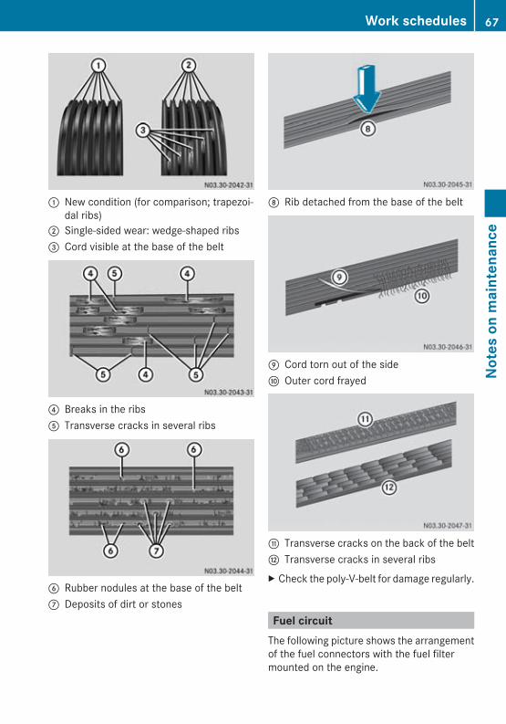
: New condition (for comparison; trapezoi-dal ribs)
; Single-sided wear: wedge-shaped ribs= Cord visible at the base of the belt
? Breaks in the ribsA Transverse cracks in several ribs
B Rubber nodules at the base of the beltC Deposits of dirt or stones
D Rib detached from the base of the belt
E Cord torn out of the sideF Outer cord frayed
G Transverse cracks on the back of the beltH Transverse cracks in several ribsX Check the poly-V-belt for damage regularly.
Fuel circuitThe following picture shows the arrangementof the fuel connectors with the fuel filtermounted on the engine.
Work schedules 67
Note
s on
mai
nten
ance
Z
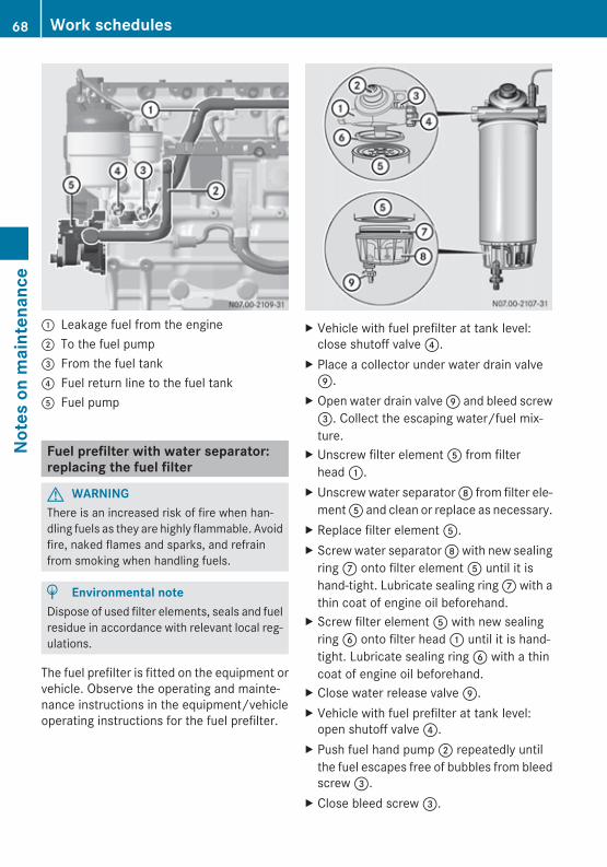
: Leakage fuel from the engine; To the fuel pump= From the fuel tank? Fuel return line to the fuel tankA Fuel pump
Fuel prefilter with water separator:replacing the fuel filter
G WARNINGThere is an increased risk of fire when han-dling fuels as they are highly flammable. Avoidfire, naked flames and sparks, and refrainfrom smoking when handling fuels.
H Environmental noteDispose of used filter elements, seals and fuelresidue in accordance with relevant local reg-ulations.
The fuel prefilter is fitted on the equipment orvehicle. Observe the operating and mainte-nance instructions in the equipment/vehicleoperating instructions for the fuel prefilter.
X Vehicle with fuel prefilter at tank level:close shutoff valve ?.
X Place a collector under water drain valveE.
X Open water drain valve E and bleed screw=. Collect the escaping water/fuel mix-ture.
X Unscrew filter element A from filterhead :.
X Unscrew water separator D from filter ele-ment A and clean or replace as necessary.
X Replace filter element A.X Screw water separator D with new sealing
ring C onto filter element A until it ishand-tight. Lubricate sealing ring C with athin coat of engine oil beforehand.
X Screw filter element A with new sealingring B onto filter head : until it is hand-tight. Lubricate sealing ring B with a thincoat of engine oil beforehand.
X Close water release valve E.X Vehicle with fuel prefilter at tank level:
open shutoff valve ?.X Push fuel hand pump ; repeatedly until
the fuel escapes free of bubbles from bleedscrew =.
X Close bleed screw =.
68 Work schedulesNo
tes
on m
aint
enan
ce
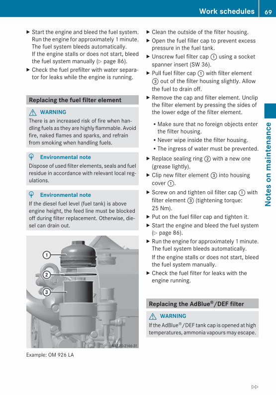
X Start the engine and bleed the fuel system.Run the engine for approximately 1 minute.The fuel system bleeds automatically.If the engine stalls or does not start, bleedthe fuel system manually (Y page 86).
X Check the fuel prefilter with water separa-tor for leaks while the engine is running.
Replacing the fuel filter element
G WARNINGThere is an increased risk of fire when han-dling fuels as they are highly flammable. Avoidfire, naked flames and sparks, and refrainfrom smoking when handling fuels.
H Environmental noteDispose of used filter elements, seals and fuelresidue in accordance with relevant local reg-ulations.
H Environmental noteIf the diesel fuel level (fuel tank) is aboveengine height, the feed line must be blockedoff during filter replacement. Otherwise, die-sel can drain out.
Example: OM 926 LA
X Clean the outside of the filter housing.X Open the fuel filler cap to prevent excess
pressure in the fuel tank.X Unscrew fuel filter cap : using a socket
spanner insert (SW 36).X Pull fuel filter cap : with filter element= out of the filter housing slightly. Allowthe fuel to drain off.
X Remove the cap and filter element. Unclipthe filter element by pressing the sides ofthe lower edge of the filter element.
RMake sure that no foreign objects enterthe filter housing.RNever wipe inside the filter housing.RThe ingress of water must be prevented.
X Replace sealing ring ; with a new one(grease lightly).
X Clip new filter element = into housingcover :.
X Screw on and tighten oil filter cap : withfilter element = (tightening torque:25 Nm).
X Put on the fuel filler cap and tighten it.X Start the engine and bleed the fuel system
(Y page 86).X Run the engine for approximately 1 minute.
The fuel system bleeds automatically.If the engine stalls or does not start, bleedthe fuel system manually.
X Check the fuel filter for leaks with theengine running.
Replacing the AdBlue®/DEF filter
G WARNINGIf the AdBlue®/DEF tank cap is opened at hightemperatures, ammonia vapours may escape.
Work schedules 69
Note
s on
mai
nten
ance
Z
Ammonia vapours have a pungent odour andparticularly irritate:RskinRmucous membranesReyesThe vapours may cause a burning sensationin the eyes, nose and throat as well as irrita-tion of the throat and watering eyes.Avoid inhaling ammonia vapours.
G WARNINGAdBlue®/DEF must not come into contactwith skin, eyes or clothing.RIf AdBlue®/DEF comes into contact with
your eyes or skin, rinse affected areas withclean water immediately.RIf AdBlue®/DEF is swallowed, immediately
rinse your mouth out with a lot of cleanwater and drink plenty of water.RChange clothing that is soiled with
AdBlue®/DEF immediately.RIf allergic reactions occur, consult a doctor
immediately.Keep AdBlue®/DEF out of the reach of chil-dren.
G WARNINGThe AdBlue®/DEF lines and all connectedcomponents are pressurised during operationand could be hot, even after the engine hasbeen switched off. There is a risk of burns.When opening the pressurised system, thereis a risk of scalding due to hot AdBlue®/DEFspraying out.RWait at least 5 minutes after switching off
the engine before starting work on theexhaust gas aftertreatment system.ROpen line connections and caps on system
components slowly. Cover the area thatyou are disconnecting with a cloth.RWear suitable protective gloves, protective
clothing and safety goggles.
! If AdBlue®/DEF gets into the coolant cir-cuit (even minute amounts), thermostatsand temperature sensors will be damaged.RAlways keep AdBlue®/DEF completely
separate from other service products.RDo not use the same containers and fluid
collecting pans for AdBlue®/DEF andother service products.RDo not continue to use service products
that contain traces of AdBlue®/DEF.
! Individual components of the BlueTec®
system react very sensitively to even theslightest trace of impurities in AdBlue®/DEF.ROnly use containers and fluid collecting
pans that are clean and suitable forAdBlue®/DEF.RDo not continue to use AdBlue®/DEF
which contains traces of impurities.
Fire fighting measuresAdBlue®/DEF is not flammable. In the eventof a fire, NH3 (ammonia) may be released.This may result in a risk of poisoning. Meas-ures to extinguish a fire must therefore beadapted to suit the surroundings.
H Environmental noteDisposing of AdBlue®/DEF:RDue to its easy degradability, small
amounts of spilt AdBlue®/DEF can bewashed into the sewage system withoutany problems.RLarger amounts of AdBlue®/DEF must be
disposed of correctly, observing the regu-lations on waste treatment/disposal.RPackaging that is contaminated with
AdBlue®/DEF residue must be treated inthe same way as AdBlue®. Packagingshould be emptied as thoroughly as possi-ble, cleaned appropriately and then recy-cled.
70 Work schedulesNo
tes
on m
aint
enan
ce
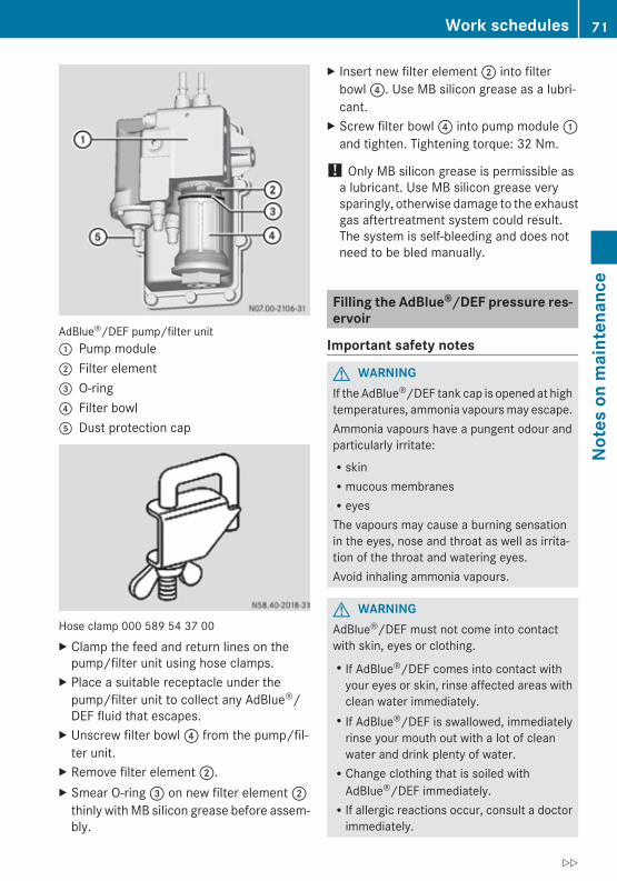
AdBlue®/DEF pump/filter unit: Pump module; Filter element= O-ring? Filter bowlA Dust protection cap
Hose clamp 000 589 54 37 00X Clamp the feed and return lines on the
pump/filter unit using hose clamps.X Place a suitable receptacle under the
pump/filter unit to collect any AdBlue®/DEF fluid that escapes.
X Unscrew filter bowl ? from the pump/fil-ter unit.
X Remove filter element ;.X Smear O-ring = on new filter element ;
thinly with MB silicon grease before assem-bly.
X Insert new filter element ; into filterbowl ?. Use MB silicon grease as a lubri-cant.
X Screw filter bowl ? into pump module :and tighten. Tightening torque: 32 Nm.
! Only MB silicon grease is permissible asa lubricant. Use MB silicon grease verysparingly, otherwise damage to the exhaustgas aftertreatment system could result.The system is self-bleeding and does notneed to be bled manually.
Filling the AdBlue®/DEF pressure res-ervoir
Important safety notes
G WARNINGIf the AdBlue®/DEF tank cap is opened at hightemperatures, ammonia vapours may escape.Ammonia vapours have a pungent odour andparticularly irritate:RskinRmucous membranesReyesThe vapours may cause a burning sensationin the eyes, nose and throat as well as irrita-tion of the throat and watering eyes.Avoid inhaling ammonia vapours.
G WARNINGAdBlue®/DEF must not come into contactwith skin, eyes or clothing.RIf AdBlue®/DEF comes into contact with
your eyes or skin, rinse affected areas withclean water immediately.RIf AdBlue®/DEF is swallowed, immediately
rinse your mouth out with a lot of cleanwater and drink plenty of water.RChange clothing that is soiled with
AdBlue®/DEF immediately.RIf allergic reactions occur, consult a doctor
immediately.
Work schedules 71
Note
s on
mai
nten
ance
Z
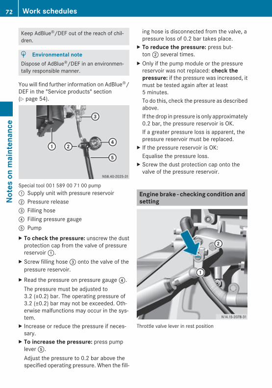
Keep AdBlue®/DEF out of the reach of chil-dren.
H Environmental noteDispose of AdBlue®/DEF in an environmen-tally responsible manner.
You will find further information on AdBlue®/DEF in the "Service products" section(Y page 54).
Special tool 001 589 00 71 00 pump: Supply unit with pressure reservoir; Pressure release= Filling hose? Filling pressure gaugeA PumpX To check the pressure: unscrew the dust
protection cap from the valve of pressurereservoir :.
X Screw filling hose = onto the valve of thepressure reservoir.
X Read the pressure on pressure gauge ?.The pressure must be adjusted to3.2 (±0.2) bar. The operating pressure of3.2 (±0.2) bar may not be exceeded. Oth-erwise malfunctions may occur in the sys-tem.
X Increase or reduce the pressure if neces-sary.
X To increase the pressure: press pumplever A.Adjust the pressure to 0.2 bar above thespecified operating pressure. When the fill-
ing hose is disconnected from the valve, apressure loss of 0.2 bar takes place.
X To reduce the pressure: press but-ton ; several times.
X Only if the pump module or the pressurereservoir was not replaced: check the pressure: if the pressure was increased, itmust be tested again after at least5 minutes.To do this, check the pressure as describedabove.If the drop in pressure is only approximately0.2 bar, the pressure reservoir is OK.If a greater pressure loss is apparent, thepressure reservoir must be replaced.
X If the pressure reservoir is OK:Equalise the pressure loss.
X Screw the dust protection cap onto thevalve of the pressure reservoir.
Engine brake - checking condition andsetting
Throttle valve lever in rest position
72 Work schedulesNo
tes
on m
aint
enan
ce
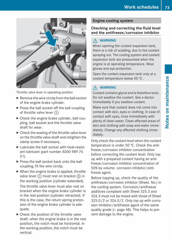
Throttle valve lever in operating positionX Remove the wire circlip from the ball socket
of the engine brake cylinder.X Press the ball socket off the ball coupling
of throttle valve lever :.X Check the engine brake cylinder, ball cou-
pling, ball socket and the throttle valveshaft for wear.
X Check the seating of the throttle valve leveron the throttle valve shaft and retighten theclamp screw if necessary.
X Lubricate the ball socket with heat-resist-ant lubricant (part number A000 989 7651).
X Press the ball socket back onto the ballcoupling, fit the wire circlip.
X When the engine brake is applied, throttlevalve lever : must rest on bracket ; inthe working position (cylinder extended).The throttle valve lever must also rest onbracket when the engine brake cylinder isin the rest position (cylinder retracted). Ifthis is the case, the return spring preten-sion of the engine brake cylinder is ade-quate.
X Check the position of the throttle valveshaft: when the engine brake is in the restposition, the notch must be horizontal. Inthe working position, the notch must bevertical.
Engine cooling system
Checking and correcting the fluid leveland the antifreeze/corrosion inhibitor
G WARNINGWhen opening the coolant expansion tank,there is a risk of scalding, due to hot coolantspraying out. The cooling system and coolantexpansion tank are pressurised when theengine is at operating temperature. Weargloves and eye protection.Open the coolant expansion tank only at acoolant temperature below 50 † .
G WARNINGCoolant contains glycol and is therefore toxic.Do not swallow the coolant. See a doctorimmediately if you swallow coolant.Make sure that coolant does not come intocontact with skin, eyes or clothing. In case ofcontact with eyes, rinse immediately withplenty of clean water. Clean affected areas ofskin and clothing with soap and water imme-diately. Change any affected clothing imme-diately.
Only check the coolant level when the coolanttemperature is under 50 †. Check the anti-freeze/corrosion inhibitor concentrationbefore correcting the coolant level. Only topup with a prepared coolant having an anti-freeze/corrosion inhibitor concentration of50% by volume. corrosion inhibitor/anti-freeze agent.Before topping up, check the quality of theantifreeze/corrosion inhibitor (Sheet. No.) inthe cooling system. Corrosion/antifreezeadditives compliant with Sheet 325.3 and326.3 must not be mixed with those of Sheet325.0/2 or 326.0/2. Only top up with corro-sion inhibitor/antifreeze agent of the samequality grade (Y page 48). This helps to pre-vent damage to the engine.
Work schedules 73
Note
s on
mai
nten
ance
Z
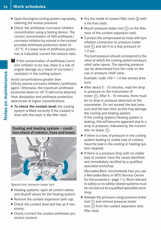
X Open the engine cooling system cap slowly,relieving the excess pressure.
X Check the antifreeze/corrosion inhibitorconcentration using a testing device. Thecorrect concentration of 50% antifreeze/corrosion inhibitor by volume in the coolantprovides antifreeze protection down toÒ37 †. If a lower level of antifreeze protec-tion is indicated, correct the mixture ratio.
! If the concentration of antifreeze/corro-sion inhibitor is too low, there is a risk ofengine damage as a result of corrosion/cavitation in the cooling system.
Avoid concentrations greater than55% by volume corrosion inhibitor/antifreezeagent. Otherwise, the maximum antifreezeprotection down to Ò45 † will not be attained.Heat dissipation and antifreeze protectiondeteriorate at higher concentrations.X To check the coolant level: the cooling
system is filled correctly if the coolant islevel with the mark in the filler neck.
Cooling and heating system – condi-tion check of radiator, lines and hoses
Special tool: pressure tester toolX Heating systems: open all control valves
and shutoff valves for the heating system.X Remove the coolant expansion tank cap.X Check the coolant level and top up if nec-
essary.X Check/correct the coolant antifreeze pro-
tection content.
X Dry the inside of coolant filler neck ; witha lint-free cloth.
X Mount pressure tester tool : on the fillerneck of the coolant expansion tank.
X Connect the compressed-air hose with tyreinflation connection to pressure testertool : and set it to a test pressure of1.0 bar.The test pressure should correspond to thevalue at which the cooling system pressurerelief valve opens. The opening pressurecan be determined from the code on thecap or pressure relief valve.Example: code 100 = 1.0 bar excess pres-sure.
X After about 5 - 10 minutes, read the dropin pressure on the manometer oftester :. After 5 - 10 minutes, there mustbe no drop in pressure detected on themanometer. Do not exceed the test pres-sure and the test time, as this may damagethe cooling and heating system.If the cooling system/heating system isleaking, this will become apparent due to adrop in pressure, indicated by the manom-eter on tester :.
X If there is a loss of pressure in the coolingsystem leading to visible loss of coolant,have the leak in the cooling or heating sys-tem repaired.
X If there is a pressure drop with no visibleloss of coolant: have the cause identifiedand immediately rectified by a qualifiedspecialist workshop.Mercedes-Benz recommends that you usea Mercedes-Benz or MTU Service Centrefor this purpose (Y page 11). Work relevantto safety or on safety-related systems mustbe carried out at a qualified specialist work-shop.
X Release the pressure using pressure testertool : and remove pressure testertool : from the coolant expansion tankfiller neck.
74 Work schedulesNo
tes
on m
aint
enan
ce
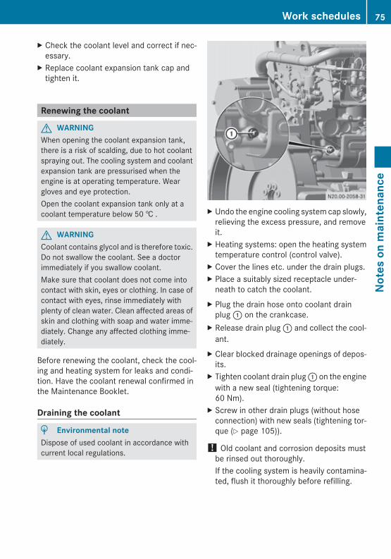
X Check the coolant level and correct if nec-essary.
X Replace coolant expansion tank cap andtighten it.
Renewing the coolant
G WARNINGWhen opening the coolant expansion tank,there is a risk of scalding, due to hot coolantspraying out. The cooling system and coolantexpansion tank are pressurised when theengine is at operating temperature. Weargloves and eye protection.Open the coolant expansion tank only at acoolant temperature below 50 † .
G WARNINGCoolant contains glycol and is therefore toxic.Do not swallow the coolant. See a doctorimmediately if you swallow coolant.Make sure that coolant does not come intocontact with skin, eyes or clothing. In case ofcontact with eyes, rinse immediately withplenty of clean water. Clean affected areas ofskin and clothing with soap and water imme-diately. Change any affected clothing imme-diately.
Before renewing the coolant, check the cool-ing and heating system for leaks and condi-tion. Have the coolant renewal confirmed inthe Maintenance Booklet.
Draining the coolant
H Environmental noteDispose of used coolant in accordance withcurrent local regulations.
X Undo the engine cooling system cap slowly,relieving the excess pressure, and removeit.
X Heating systems: open the heating systemtemperature control (control valve).
X Cover the lines etc. under the drain plugs.X Place a suitably sized receptacle under-
neath to catch the coolant.X Plug the drain hose onto coolant drain
plug : on the crankcase.X Release drain plug : and collect the cool-
ant.X Clear blocked drainage openings of depos-
its.X Tighten coolant drain plug : on the engine
with a new seal (tightening torque:60 Nm).
X Screw in other drain plugs (without hoseconnection) with new seals (tightening tor-que (Y page 105)).
! Old coolant and corrosion deposits mustbe rinsed out thoroughly.If the cooling system is heavily contamina-ted, flush it thoroughly before refilling.
Work schedules 75
Note
s on
mai
nten
ance
Z
Adding coolantX Add coolant.X Start the engine and run it at varying
speeds for approximately 1 minute.X Add coolant mixed to the prescribed ratio
until it reaches the lower edge of the fillerneck.
X Switch off the engine and seal the coolingsystem again.
Observe any further information in the oper-ating instructions from the equipment/vehi-cle manufacturer.
! Corrosion inhibitors/antifreeze agentsthat comply with Sheet 325.3 and 326.3must not be mixed with those of Sheet325.0/2 or 326.0/2. This prevents dam-age to the engine cooling system.
Cleaning the cooling system
G WARNINGThe cooling system is pressurised. Hot cool-ant can escape under pressure when the cool-ing system is opened and scald your skin andeyes.ROnly open the cooling system at coolant
temperatures below 90 †.RUnscrew the cap slowly and release any
excess pressure completely before open-ing the cap fully.RWear suitable protective gloves, protective
clothing and safety goggles when handlingcoolant.
G WARNINGCoolant contains glycol and is therefore toxic.Do not swallow the coolant. See a doctorimmediately if you swallow coolant.Make sure that coolant does not come intocontact with skin, eyes or clothing. In case ofcontact with eyes, rinse immediately withplenty of clean water. Clean affected areas ofskin and clothing with soap and water imme-
diately. Change any affected clothing imme-diately.
H Environmental noteCollect used coolant, cleaning solutions anddetergents and dispose of them in an envi-ronmentally responsible manner in accord-ance with applicable local regulations.
X Remove foreign objects (dust, insects, etc.)from the radiator core fin. You can do thisby blowing them out with compressed air,or by spraying water from the rear side ofthe radiator.
! Only apply moderate pressure whencleaning, since the radiator fins could oth-erwise be damaged.
X Drain off coolant when the engine is cold(Y page 75).
X If a heater is connected to the cooling sys-tem, open the regulating valves fully.
Flushing the cooling systemX Fill the cooling system with fresh water and
leave the system running for approximatefive minutes.
X Switch off the engine and drain off thewater completely.
X Repeat the flushing process at least twice.X Fill the cooling system with new corrosion
inhibitor/antifreeze agent. Observe theantifreeze protection (Y page 73).
Degreasing the cooling systemX If necessary, degrease the cooling system
with a suitable cleaning agent. Informationis available from any Mercedes-Benz orMTU Service Centre (Y page 11).
76 Work schedulesNo
tes
on m
aint
enan
ce
Checking for leaks and general condi-tion – assembliesX Carry out a visual inspection of the engine
for signs of leaks. Slight dampness aroundsealed joints can be ignored.
! More severe leaks, where there is con-stant oil loss, must be rectified immedi-ately.
Lines, hoses and sensor cables –checking for leaks and general condi-tionX Carry out a visual check for leaks from lines
and hoses. At the same time, check that alllines and hoses are undamaged, are routedso they do not chafe and are secured cor-rectly.
X Check the intake pipe between the air filterand the engine for leaks and check the con-dition.
X Check the intake pipe and bellows from theair filter as well as the charge-air cooler forthe engine for damage and for leaks at con-nection points.
X Check the air compressor intake pipe andcrankcase ventilation for damage and leaksat connection points.
X Check all hose clamps for correct seating.Retighten or replace loose hose clamps.
X Replace porous, leaking or damaged linesand bellows.
G WARNINGThe engine becomes very hot while it is run-ning and remains so for some time after it hasstopped. It will cause burns if touched.Before starting any work on the engine, allowall engine parts to cool down, or wear suitablegloves and items of clothing to protect your-self from being burned on hot engine compo-nents.
G WARNINGThere is a danger of limbs being caught, pulledin and thereby crushed or severed by rotatingengine parts. Therefore you should:Rkeep a safe distance between yourself and
rotating engine parts, including when theengine is being started.Rwait until all engine parts have stopped
moving before carrying out any work on theengine.Rwear work clothing which is properly fas-
tened and close-fitting. Wear a hair net ifnecessary. Remove jewellery such aswatches and necklaces.
Work schedules 77
Note
s on
mai
nten
ance
Z

78
Decommissioning the engine ............ 80Protecting the engine ......................... 81
79
Deco
mm
issi
on a
nd p
rote
ctio
n
Decommissioning the engine
Particular measures are necessary when theengine/vehicle/equipment is to be decom-missioned.Decommissioned engines are engines thatare not operated for a month or more afterassembly or after repair work has been car-ried out.For engines that have been run in, this appliesafter 12 months' standing time.
Decommissioning for up to 12monthsRWhen decommissioning an engine/vehi-
cle/equipment, keep it in a covered, dryand well-ventilated area. The room temper-ature should not fall below -10 † in orderprevent the AdBlue®/DEF from freezing.If this is not possible, these measures mustbe carried out after 6 months rather than12.
Measures prior to decommissioningRClean the engine/vehicle/equipment thor-
oughly.RRemove any patches of corrosion from the
engine.RChange the engine oil and oil filter if the last
oil change was carried out more than20,000 km (around 300 operating hours)ago or if the oil is older than 12 months.RDisconnect the earth lines from the batter-
ies (this prevents self-discharge due toclosed-circuit accessories).RCharge the batteries. Check the battery
fluid levels before and after charging.RCheck and adjust the concentration of anti-
corrosion/antifreeze additives in the cool-ant.RCheck and adjust the level of coolant or
renew coolant.
RFill up the AdBlue®/DEF supply reservoircompletely so that AdBlue® cannot crys-tallise out.RFuel prefilter with heated water separator:
drain off the water separator.Engine/vehicle/equipment with exhaust gas aftertreatment RDecommissioning for more than 12
months: fill up the AdBlue®/DEF supplyreservoir completely.RDecommissioning for more than 24
months: drain off and dispose of AdBlue®/DEF. When disposing of AdBlue®/DEF,observe the relevant national laws and reg-ulations.RWhen outside temperatures are low,
AdBlue®/DEF crystals may form on thecoiled hose between the engine andsilencer. Remove the crystals with plenty ofwater.
Engine/vehicle/equipment run on FAME (Fatty Acid Methyl Ester) bio-diesel fuelREmpty the fuel tank to the point where the
remaining fuel still allows the engine to beoperated for 15 to 30 minutes each monthduring its decommissioned period.RStart the engine at least once a month and
leave it running for 15 to 30 minutes at anengine speed of around 900 rpm. Doing sopurges the fuel system or diesel injectionsystem with fuel. This prevents any caulk-ing of the fuel injectors.
Measures during decommissioningRBefore starting the engine, check the
engine oil level and the coolant level.RStart the engine and leave it running for
15 to 30 minutes at an engine speed ofno more than 900 rpm.RWhile the engine is running, observe the
indicators for oil pressure, coolant temper-ature and oil temperature.RWhile the engine is running, select every
gear that can be selected while stationary.
80 Decommissioning the engineDe
com
mis
sion
and
pro
tect
ion
RLeave the engine running until the air com-pressor cutoff pressure is reached.RFuel prefilter with heated water separator:
drain off the water separator.RRecharge the batteries every three months.
Check the battery fluid levels before andafter charging.RChange the engine oil and oil filter every
24 months. Measures prior to decommissioningREmpty the fuel tank and fill up with new fuel.
When disposing of fuels, observe the rele-vant national laws and regulations.RFuel prefilter with heated water separator:
replace filter element.RReplace fuel filter.RReplace air filter cartridge.RChange engine oil and oil filter.RCheck coolant level.RIf coolant needs refilling, check and adjust
the concentration of anticorrosion/anti-freeze in the coolant. Before refilling cool-ant, note the quality of the previously filledanticorrosion/antifreeze (Y page 48).RCheck the charge status of the battery and
recharge if necessary. Check the batteryfluid levels before and after charging.RConnect the earth lines to the batteries.RCheck that the electrical system is func-
tioning correctly.RCheck cables, hoses and lines for tears and
leaks.RStart the engine and leave it running for
15 to 30 minutes at an engine speed ofno more than 900 rpm.RWhile the engine is running, observe the
indicators for oil pressure, coolant temper-ature and oil temperature.RVehicles with auxiliary heating: activate the
auxiliary heating.RCheck oil levels in the steering system,
engine, transmission and drive axles.
RCheck that the electrical system, steeringsystem and brakes are functioning cor-rectly.RClean the engine/vehicle/equipment thor-
oughly.
Protecting the engine
Engine protective treatment applies to all fit-ted and removed vehicle, industrial and OEMengines as well as new engines, recondi-tioned engines and short block engines.Engines that have been removed must be pro-tected against moisture (rain or spray water)using special measures.
Protective treatment for up to 12months
On new engines no additional protectionmeasures are required, as long as initial oper-ation oil compliant with Sheet 225.6 and cool-ant were added at the engine factory. Engineswhich have covered a distance of up to300 km or which have been operated for upto 6 hours may be considered new.RClean the engine thoroughly and remove
patches of corrosion.RAll machined exterior and unpreserved sur-
faces must be greased or sprayed withpreservative agent according to Sheet385.4. This is regardless of the duration ofthe protective treatment. Examples of thisare the flywheel and pulley keyway.RWhere possible, carry out protective meas-
ures on the fitted engine in the storagelocation.RAfter protective measures are complete,
the engine must not be started again.REngine oil and coolant must be filled to the
maximum level. Observe the temperatureranges when selecting engine oil and cool-ant.
Protecting the engine 81
Deco
mm
issi
on a
nd p
rote
ctio
n
RClose off all openings on the engine (e.g.on the charge-air housing, exhaust etc.)with an oil-soaked rag.RDrain off the coolant completely for
engines that have been removed. Unscrewthe coolant drain plug on the engine blockto do so. When screwing in the coolantdrain plug, observe the tightening torque.RRelieve the tension in the poly-V-belt. The
poly-V-belt can remain routed.RIf the engine has been filled with coolant,
the cooling system must first be filled withwater. It must then be filled with a mixtureof water and improver compliant withSheet 311.0. Coolant without antifreezeprotection compliant with Sheet 312.0 mayalso be used.
Protective treatment for 12 to 36months
Carry out all measures in "Protective treat-ment for up to 12 months". The fuel system,combustion chambers and air compressoralso require protective measures.
Carry out protective measures for thefuel systemX Completely fill the fuel tank with diesel fuel.X Start the engine and allow it to run for
15-30 minutes at approximately 900 rpm.
Carry out protective measures for thecombustion chambersOnly carry out protection measures for thecombustion chambers when the engine iscold (coolant temperature under 50 † ).Only use initial operation oil compliant withSheet 225.6 for the protection of the com-bustion chambers.X Detach the charge-air housing from the cyl-
inder heads.X Briefly press the start button on the engine.
At the same time, pour approximately
15 – 20 cm3 initial operation oil into eachcylinder.
Protecting the air compressorCarry out the protection of the air compressorat the same time as the combustion chamberprotection.X On the air intake side of the air compressor,
pour a maximum of 5 cm3 of initial opera-tion oil compliant with Sheet 225.6 into theair compressor.
After protective measuresX Refit all removed engine parts. Observe the
tightening torques.
! After protective measures are complete,the engine must not be started again.
Protective treatment for longer than36 months
When carrying out protective treatment forover 36 or 18 months, repeat the protectionmeasures as in "Protective treatment for 12to 36 months".X Drain off engine oil that has been added.X The oil filter does not have to be replaced.
Shipping by sea or engine protectivetreatment in tropical countries
Carry out all measures in "Protective treat-ment for 12 to 36 months". The fuel system,combustion chambers and air compressoralso require protective measures.
82 Protecting the engineDe
com
mis
sion
and
pro
tect
ion
The following work is required for enginesthat have been run in (distance of over300 km or running time of over 6 operatinghours):X Drain off engine oil and replace the oil filter.
Add initial operation oil compliant withSheet 225.6.
X Fill or top up the cooling system with thespecified coolant. Before refilling coolant,note the quality of the previously filled anti-corrosion/antifreeze (Y page 48).
X Carry out protective measures for the fuelsystem.
X Warm up the engine at medium enginespeeds and allow it to run for approximately5 to 10 minutes at operating temperature(coolant temperature 75-95 †).
X Switch off the engine and check the oillevel.
X Add oil up to the upper marking on the oildipstick.
X Hermetically seal all engine openings.X Drain off the coolant completely for
engines that have been removed. Unscrewthe coolant drain plug on the engine blockto do so.
Re-commissioningX Remove all plugs or rags that have been fit-
ted.X Fit removed engines and connect all
cables, hoses and lines.X Remove protective agents and greases
from all protected areas, such as the fly-wheel, pulley keyway etc.
X Tension the poly-V-belt as per the regula-tions.
X Renew the engine oil and replace the oil fil-ter before re-commissioning. Add oil up tothe upper marking on the oil dipstick.
X Add coolant. Observe the concentration ofanticorrosion/antifreeze additives. Beforerefilling coolant, note the quality of the pre-
viously filled anticorrosion/antifreeze(Y page 48).
X New engines: add initial operation oil com-pliant with Sheet 225.6.
X Engines that have been run in (distance ofover 300 km or running time of over6 operating hours): before starting theengine, lubricate the lubrication points onthe engine as necessary, e.g. ball couplingsor engine brakes.
X Start the engine and leave it running untilit is at operating temperature (coolant tem-perature approximately 75 to 95 †). Whiledoing so, observe the indicators for oil pres-sure, coolant temperature and oil temper-ature.
Protecting the engine 83
Deco
mm
issi
on a
nd p
rote
ctio
n

84
General notes ...................................... 86Bleeding the fuel system .................... 86Activating engine emergency run-ning mode ............................................ 87Troubleshooting .................................. 89BlueTec® exhaust gas aftertreat-ment indicator (on-highway ver-sion) ..................................................... 94BlueTec® exhaust gas aftertreat-ment indicator (off-highway ver-sion) ..................................................... 95Replacing the poly-V-belt ................... 97
85
Brea
kdow
n as
sist
ance
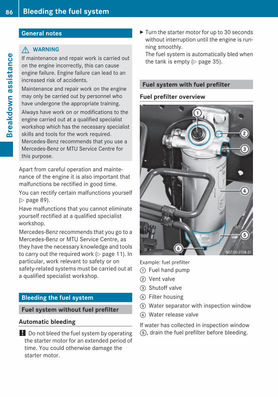
General notes
G WARNINGIf maintenance and repair work is carried outon the engine incorrectly, this can causeengine failure. Engine failure can lead to anincreased risk of accidents.Maintenance and repair work on the enginemay only be carried out by personnel whohave undergone the appropriate training.Always have work on or modifications to theengine carried out at a qualified specialistworkshop which has the necessary specialistskills and tools for the work required.Mercedes-Benz recommends that you use aMercedes-Benz or MTU Service Centre forthis purpose.
Apart from careful operation and mainte-nance of the engine it is also important thatmalfunctions be rectified in good time.You can rectify certain malfunctions yourself(Y page 89).Have malfunctions that you cannot eliminateyourself rectified at a qualified specialistworkshop.Mercedes-Benz recommends that you go to aMercedes-Benz or MTU Service Centre, asthey have the necessary knowledge and toolsto carry out the required work (Y page 11). Inparticular, work relevant to safety or onsafety-related systems must be carried out ata qualified specialist workshop.
Bleeding the fuel system
Fuel system without fuel prefilter
Automatic bleeding! Do not bleed the fuel system by operating
the starter motor for an extended period oftime. You could otherwise damage thestarter motor.
X Turn the starter motor for up to 30 secondswithout interruption until the engine is run-ning smoothly.The fuel system is automatically bled whenthe tank is empty (Y page 35).
Fuel system with fuel prefilter
Fuel prefilter overview
Example: fuel prefilter: Fuel hand pump; Vent valve= Shutoff valve? Filter housingA Water separator with inspection windowB Water release valve
If water has collected in inspection windowA, drain the fuel prefilter before bleeding.
86 Bleeding the fuel systemBr
eakd
own
assi
stan
ce
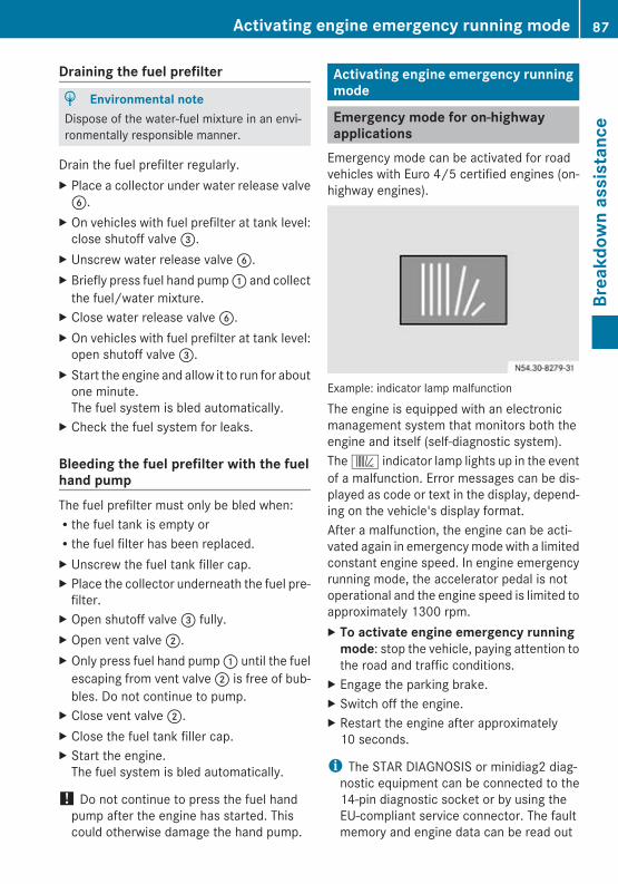
Draining the fuel prefilter
H Environmental noteDispose of the water-fuel mixture in an envi-ronmentally responsible manner.
Drain the fuel prefilter regularly.X Place a collector under water release valveB.
X On vehicles with fuel prefilter at tank level:close shutoff valve =.
X Unscrew water release valve B.X Briefly press fuel hand pump : and collect
the fuel/water mixture.X Close water release valve B.X On vehicles with fuel prefilter at tank level:
open shutoff valve =.X Start the engine and allow it to run for about
one minute.The fuel system is bled automatically.
X Check the fuel system for leaks.
Bleeding the fuel prefilter with the fuelhand pumpThe fuel prefilter must only be bled when:Rthe fuel tank is empty orRthe fuel filter has been replaced.X Unscrew the fuel tank filler cap.X Place the collector underneath the fuel pre-
filter.X Open shutoff valve = fully.X Open vent valve ;.X Only press fuel hand pump : until the fuel
escaping from vent valve ; is free of bub-bles. Do not continue to pump.
X Close vent valve ;.X Close the fuel tank filler cap.X Start the engine.
The fuel system is bled automatically.
! Do not continue to press the fuel handpump after the engine has started. Thiscould otherwise damage the hand pump.
Activating engine emergency runningmode
Emergency mode for on-highwayapplications
Emergency mode can be activated for roadvehicles with Euro 4/5 certified engines (on-highway engines).
Example: indicator lamp malfunction
The engine is equipped with an electronicmanagement system that monitors both theengine and itself (self-diagnostic system).The k indicator lamp lights up in the eventof a malfunction. Error messages can be dis-played as code or text in the display, depend-ing on the vehicle's display format.After a malfunction, the engine can be acti-vated again in emergency mode with a limitedconstant engine speed. In engine emergencyrunning mode, the accelerator pedal is notoperational and the engine speed is limited toapproximately 1300 rpm.X To activate engine emergency running
mode: stop the vehicle, paying attention tothe road and traffic conditions.
X Engage the parking brake.X Switch off the engine.X Restart the engine after approximately
10 seconds.
i The STAR DIAGNOSIS or minidiag2 diag-nostic equipment can be connected to the14-pin diagnostic socket or by using theEU-compliant service connector. The faultmemory and engine data can be read out
Activating engine emergency running mode 87
Brea
kdow
n as
sist
ance
Z
using this diagnostic equipment. Informa-tion is available from any Mercedes-Benz orMTU Service Centre (Y page 11).
Emergency mode for off-highwayapplications
Full engine output can be activated with anemergency switch for devices with Euromot3B or Tier 4i certified engines (off-highwayapplications). Emergency mode can only beactivated for 30 minutes, and only if the vehi-cle has the appropriate equipment.For further information, see the device'soperating instructions.
88 Activating engine emergency running modeBr
eakd
own
assi
stan
ce
Troubleshooting
Engine problems
G WARNINGIf maintenance work is carried out incorrectly, the operating safety of your vehicle may be affec-ted. You could lose control of the vehicle and cause an accident. The safety systems may alsono longer be able to protect you or others as they are designed to.Always have service work carried out at a qualified specialist workshop. The qualified specialistworkshop must have the specialist skills and tools necessary to carry out the work. Mercedes-Benz recommends that you use a Mercedes-Benz or MTU Service Centre for this purpose. Inparticular, work relevant to safety or on safety-related systems must be carried out at a qualifiedspecialist workshop.
Apart from careful operation and maintenance of the engine it is also important that malfunc-tions be rectified in good time. You can rectify certain faults yourself.Have malfunctions that you cannot eliminate yourself rectified at a qualified specialist work-shop. Mercedes-Benz recommends that you use a Mercedes-Benz or MTU Service Centre forthis purpose (Y page 11).
Problem Possible causes/consequences and M Solutions
Drive pinion does notturn or turns too slowly.
Battery is not sufficiently charged.X Charge the battery.
Connecting cable to the starter motor is loose.X Tighten the cable on the terminal. If necessary, solder on a new
terminal.
Starter motor solenoid switch is faulty or starter motor is faulty.X Have it checked at a qualified specialist workshop.
Engine does not start orstalls again immedi-ately.
Fuel tank is empty.X Refill the fuel tank (Y page 41).
Fuel filter is blocked.X Replace the filter element (Y page 69).
The fuel prefilter contains water.X Drain the fuel prefilter (Y page 68).
Fuel prefilter is blocked.X Replace the filter element (Y page 68).
Fuel system or filter is leaking.X Replace the seals.
Troubleshooting 89
Brea
kdow
n as
sist
ance
Z
Problem Possible causes/consequences and M Solutions
Fuel is not resistant to cold.X Replace the fuel prefilter (Y page 68).X Replace the fuel filter (Y page 69).X Use winter fuel (Y page 52).
Incorrect engine oil viscosity.X Alter the engine oil viscosity to the conditions of use
(Y page 47).
Engine does not startcorrectly.
There is a malfunction in the engine control unit.X Read out the MR (engine control) unit, have it checked at a
qualified specialist workshop.
There are leaks or there is insufficient pressure in the low-pressurefuel circuit.X Carry out a check for leaks (visual check).X Have the pressure tested at a qualified specialist workshop.
Engine stops inadver-tently.
MR (engine control) unit is faulty (total failure).X Consult a qualified specialist workshop.
Power supply to the MR/ADM control units is interrupted or thereis a short circuit in the wiring.X Have the power supply checked at a qualified specialist work-
shop.
There are leaks or there is insufficient pressure in the low-pressurefuel circuit or the fuel pump drive is faulty.X Check for leaks (visual check).X Have the fuel pressure tested at a qualified specialist workshop.
Engine is in emergencyrunning mode.
There is an interruption to the MR/ADM control unit's data flow.X Read out the control unit's fault memory.X Have it checked at a qualified specialist workshop.
Engine surges, vibratesor runs irregularly.
Crankshaft sensor or TDC sensor (on camshaft gear wheel) isfaulty or the signal is missing.X Consult a qualified specialist workshop.
There is a malfunction in the fuel system.X Read out the fault code.X Have it checked at a qualified specialist workshop.
90 TroubleshootingBr
eakd
own
assi
stan
ce
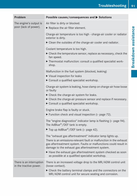
Problem Possible causes/consequences and M Solutions
The engine's output ispoor (lack of power).
Air filter is dirty or blocked.X Replace the air filter element.
Charge-air temperature is too high - charge-air cooler or radiatorexterior is dirty.X Clean the outsides of the charge-air cooler and radiator.
Coolant temperature is too high.X Check the temperature sensor, replace as necessary, check the
fan speed.X Thermostat malfunction: consult a qualified specialist work-
shop.
Malfunction in the fuel system (blocked, leaking)X Visual inspection for leaksX Consult a qualified specialist workshop.
Charge-air system is leaking, hose clamp on charge-air hose looseor faultyX Check the charge-air system for leaks.X Check the charge-air pressure sensor and replace if necessary.X Consult a qualified specialist workshop.
Engine brake flap is faulty or stuck.X Function check and visual inspection (Y page 72).
The "engine diagnostics" indicator lamp is flashing (Y page 94).The AdBlue®/DEF tank is empty.X Top up AdBlue®/DEF tank (Y page 42).
The "exhaust gas aftertreatment" indicator lamp lights up.There is an emissions-relevant fault or malfunction in the exhaustgas aftertreatment system. Faults or malfunctions could result indamage to the exhaust gas aftertreatment system.X Have the exhaust gas aftertreatment system checked as soon
as possible at a qualified specialist workshop.
There is an interruptionin the tractive power.
There is an increased voltage drop to the MR/ADM control unit(loose contact).X Check the battery terminal clamps and the connectors on the
MR/ADM control unit for secure seating and corrosion.
Troubleshooting 91
Brea
kdow
n as
sist
ance
Z
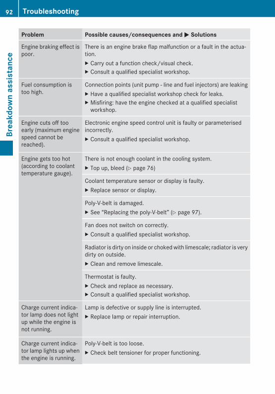
Problem Possible causes/consequences and M Solutions
Engine braking effect ispoor.
There is an engine brake flap malfunction or a fault in the actua-tion.X Carry out a function check/visual check.X Consult a qualified specialist workshop.
Fuel consumption istoo high.
Connection points (unit pump - line and fuel injectors) are leakingX Have a qualified specialist workshop check for leaks.X Misfiring: have the engine checked at a qualified specialist
workshop.
Engine cuts off tooearly (maximum enginespeed cannot bereached).
Electronic engine speed control unit is faulty or parameterisedincorrectly.X Consult a qualified specialist workshop.
Engine gets too hot(according to coolanttemperature gauge).
There is not enough coolant in the cooling system.X Top up, bleed (Y page 76)
Coolant temperature sensor or display is faulty.X Replace sensor or display.
Poly-V-belt is damaged.X See “Replacing the poly-V-belt” (Y page 97).
Fan does not switch on correctly.X Consult a qualified specialist workshop.
Radiator is dirty on inside or choked with limescale; radiator is verydirty on outside.X Clean and remove limescale.
Thermostat is faulty.X Check and replace as necessary.X Consult a qualified specialist workshop.
Charge current indica-tor lamp does not lightup while the engine isnot running.
Lamp is defective or supply line is interrupted.X Replace lamp or repair interruption.
Charge current indica-tor lamp lights up whenthe engine is running.
Poly-V-belt is too loose.X Check belt tensioner for proper functioning.
92 TroubleshootingBr
eakd
own
assi
stan
ce
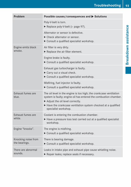
Problem Possible causes/consequences and M Solutions
Poly-V-belt is torn.X Replace poly-V-belt (Y page 97).
Alternator or sensor is defective.X Check alternator or sensor.X Consult a qualified specialist workshop.
Engine emits blacksmoke.
Air filter is very dirty.X Replace the air filter element.
Engine brake is faulty.X Consult a qualified specialist workshop.
Exhaust gas turbocharger is faulty.X Carry out a visual check.X Consult a qualified specialist workshop.
Misfiring, fuel injector is faulty.X Consult a qualified specialist workshop.
Exhaust fumes areblue.
The oil level in the engine is too high; the crankcase ventilationsystem is faulty; engine oil has entered the combustion chamber.X Adjust the oil level correctly.X Have the crankcase ventilation system checked at a qualified
specialist workshop.
Exhaust fumes arewhite.
Coolant is entering the combustion chamber.X Have a pressure loss test carried out at a qualified specialist
workshop.
Engine “knocks”. The engine is misfiring.X Consult a qualified specialist workshop.
Knocking noise fromthe bearings.
There is bearing damage.X Consult a qualified specialist workshop.
There are abnormalsounds.
Leaks in intake pipe and exhaust pipe cause whistling noise.X Repair leaks; replace seals if necessary.
Troubleshooting 93
Brea
kdow
n as
sist
ance
Z
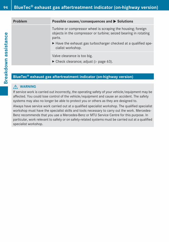
Problem Possible causes/consequences and M Solutions
Turbine or compressor wheel is scraping the housing; foreignobjects in the compressor or turbine; seized bearing in rotatingparts.X Have the exhaust gas turbocharger checked at a qualified spe-
cialist workshop.
Valve clearance is too big.X Check clearance; adjust (Y page 63).
BlueTec® exhaust gas aftertreatment indicator (on-highway version)
G WARNINGIf service work is carried out incorrectly, the operating safety of your vehicle/equipment may beaffected. You could lose control of the vehicle/equipment and cause an accident. The safetysystems may also no longer be able to protect you or others as they are designed to.Always have service work carried out at a qualified specialist workshop. The qualified specialistworkshop must have the specialist skills and tools necessary to carry out the work. Mercedes-Benz recommends that you use a Mercedes-Benz or MTU Service Centre for this purpose. Inparticular, work relevant to safety or on safety-related systems must be carried out at a qualifiedspecialist workshop.
94 BlueTec® exhaust gas aftertreatment indicator (on-highway version)Br
eakd
own
assi
stan
ce
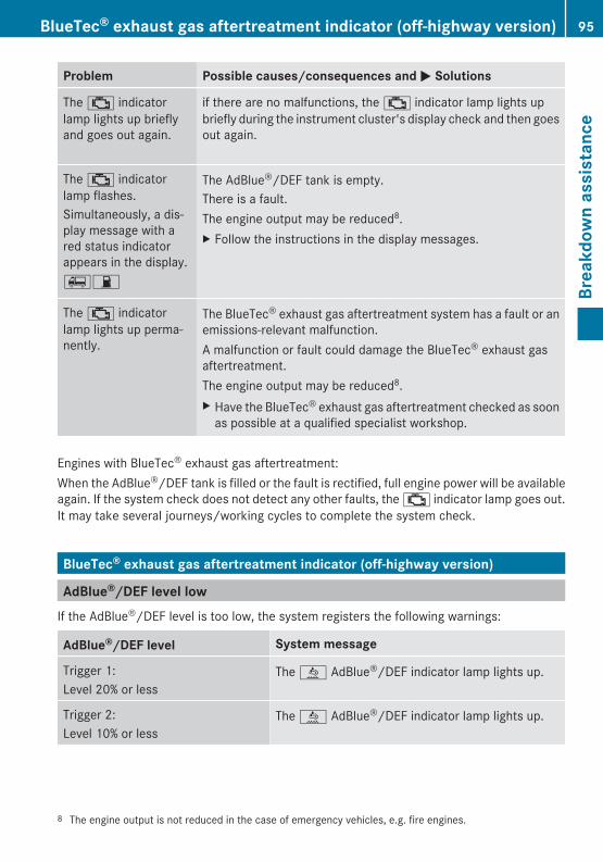
Problem Possible causes/consequences and M Solutions
The ; indicatorlamp lights up brieflyand goes out again.
if there are no malfunctions, the ; indicator lamp lights upbriefly during the instrument cluster's display check and then goesout again.
The ; indicatorlamp flashes.Simultaneously, a dis-play message with ared status indicatorappears in the display.67
The AdBlue®/DEF tank is empty.There is a fault.The engine output may be reduced8.X Follow the instructions in the display messages.
The ; indicatorlamp lights up perma-nently.
The BlueTec® exhaust gas aftertreatment system has a fault or anemissions-relevant malfunction.A malfunction or fault could damage the BlueTec® exhaust gasaftertreatment.The engine output may be reduced8.X Have the BlueTec® exhaust gas aftertreatment checked as soon
as possible at a qualified specialist workshop.
Engines with BlueTec® exhaust gas aftertreatment:When the AdBlue®/DEF tank is filled or the fault is rectified, full engine power will be availableagain. If the system check does not detect any other faults, the ; indicator lamp goes out.It may take several journeys/working cycles to complete the system check.
BlueTec® exhaust gas aftertreatment indicator (off-highway version)
AdBlue®/DEF level lowIf the AdBlue®/DEF level is too low, the system registers the following warnings:
AdBlue®/DEF level System message
Trigger 1:Level 20% or less
The å AdBlue®/DEF indicator lamp lights up.
Trigger 2:Level 10% or less
The å AdBlue®/DEF indicator lamp lights up.
8 The engine output is not reduced in the case of emergency vehicles, e.g. fire engines.
BlueTec® exhaust gas aftertreatment indicator (off-highway version) 95
Brea
kdow
n as
sist
ance
Z
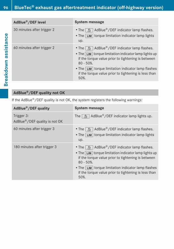
AdBlue®/DEF level System message
30 minutes after trigger 2 RThe å AdBlue®/DEF indicator lamp flashes.RThe È torque limitation indicator lamp lights
up.
60 minutes after trigger 2 RThe å AdBlue®/DEF indicator lamp flashes.RThe È torque limitation indicator lamp lights up
if the torque value prior to tightening is between80 - 50%.RThe È torque limitation indicator lamp flashes
if the torque value prior to tightening is less than50%.
AdBlue®/DEF quality not OKIf the AdBlue®/DEF quality is not OK, the system registers the following warnings:
AdBlue®/DEF quality System message
Trigger 3:AdBlue®/DEF quality is not OK
The å AdBlue®/DEF indicator lamp lights up.
60 minutes after trigger 3 RThe å AdBlue®/DEF indicator lamp flashes.RThe È torque limitation indicator lamp lights
up.
180 minutes after trigger 3 RThe å AdBlue®/DEF indicator lamp flashes.RThe È torque limitation indicator lamp lights up
if the torque value prior to tightening is between80 - 50%.RThe È torque limitation indicator lamp flashes
if the torque value prior to tightening is less than50%.
96 BlueTec® exhaust gas aftertreatment indicator (off-highway version)Br
eakd
own
assi
stan
ce
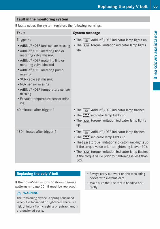
Fault in the monitoring systemIf faults occur, the system registers the following warnings:
Fault System message
Trigger 4:RAdBlue®/DEF tank sensor missingRAdBlue®/DEF metering line or
metering valve missingRAdBlue®/DEF metering line or
metering valve blockedRAdBlue®/DEF metering pump
missingRSCR cable set missingRNOx sensor missingRAdBlue®/DEF temperature sensor
missingRExhaust temperature sensor miss-
ing
RThe å AdBlue®/DEF indicator lamp lights up.RThe È torque limitation indicator lamp lights
up.
60 minutes after trigger 4 RThe å AdBlue®/DEF indicator lamp flashes.RThe ! indicator lamp lights up.RThe È torque limitation indicator lamp lights
up.
180 minutes after trigger 4 RThe å AdBlue®/DEF indicator lamp flashes.RThe ! indicator lamp lights up.RThe È torque limitation indicator lamp lights up
if the torque value prior to tightening is over 50%.RThe È torque limitation indicator lamp flashes
if the torque value prior to tightening is less than50%.
Replacing the poly-V-belt
If the poly-V-belt is torn or shows damagepatterns (Y page 66), it must be replaced.
G WARNINGThe tensioning device is spring-tensioned.When it is loosened or tightened, there is arisk of injury from crushing or entrapment inpretensioned parts.
RAlways carry out work on the tensioningdevice with extreme care.RMake sure that the tool is handled cor-
rectly.
Replacing the poly-V-belt 97
Brea
kdow
n as
sist
ance
Z
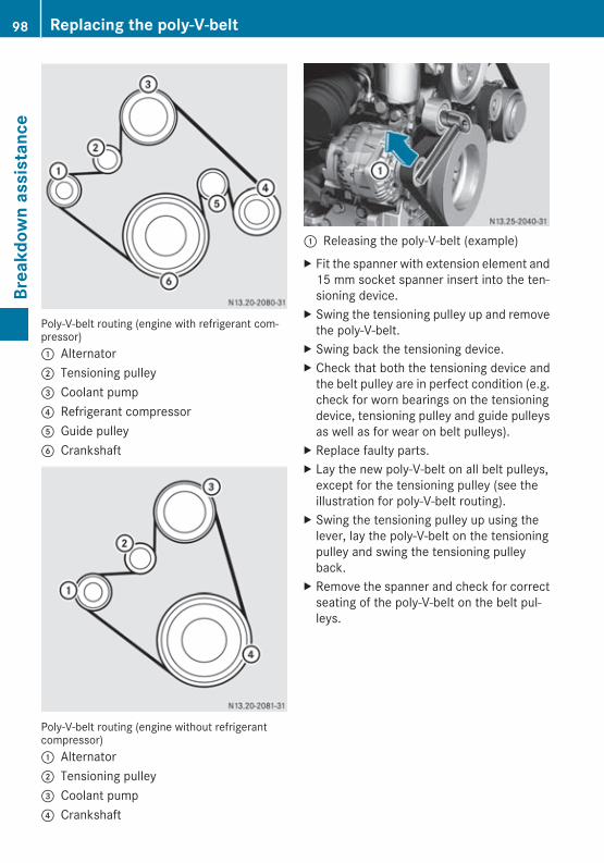
Poly-V-belt routing (engine with refrigerant com-pressor): Alternator; Tensioning pulley= Coolant pump? Refrigerant compressorA Guide pulleyB Crankshaft
Poly-V-belt routing (engine without refrigerantcompressor): Alternator; Tensioning pulley= Coolant pump? Crankshaft
: Releasing the poly-V-belt (example)X Fit the spanner with extension element and
15 mm socket spanner insert into the ten-sioning device.
X Swing the tensioning pulley up and removethe poly-V-belt.
X Swing back the tensioning device.X Check that both the tensioning device and
the belt pulley are in perfect condition (e.g.check for worn bearings on the tensioningdevice, tensioning pulley and guide pulleysas well as for wear on belt pulleys).
X Replace faulty parts.X Lay the new poly-V-belt on all belt pulleys,
except for the tensioning pulley (see theillustration for poly-V-belt routing).
X Swing the tensioning pulley up using thelever, lay the poly-V-belt on the tensioningpulley and swing the tensioning pulleyback.
X Remove the spanner and check for correctseating of the poly-V-belt on the belt pul-leys.
98 Replacing the poly-V-beltBr
eakd
own
assi
stan
ce
Vehicle identification plate .............. 100Information on the identificationplate ................................................... 100Engine model designation ................ 100Engine data card ............................... 100Engine data ........................................ 101Operating restriction - off-highwayversion ............................................... 106
99
Tech
nica
l dat
a
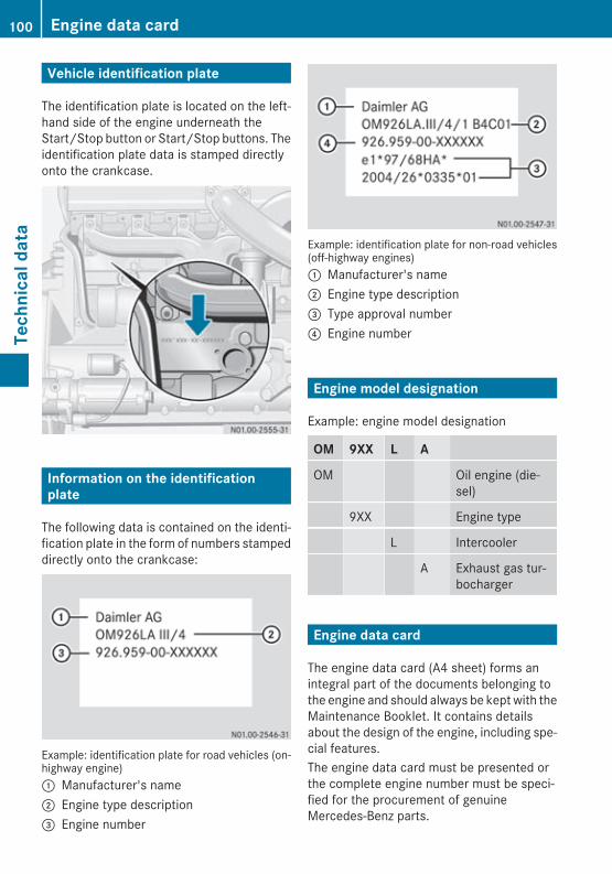
Vehicle identification plate
The identification plate is located on the left-hand side of the engine underneath theStart/Stop button or Start/Stop buttons. Theidentification plate data is stamped directlyonto the crankcase.
Information on the identificationplate
The following data is contained on the identi-fication plate in the form of numbers stampeddirectly onto the crankcase:
Example: identification plate for road vehicles (on-highway engine): Manufacturer's name; Engine type description= Engine number
Example: identification plate for non-road vehicles(off-highway engines): Manufacturer's name; Engine type description= Type approval number? Engine number
Engine model designation
Example: engine model designation
OM 9XX L A
OM Oil engine (die-sel)
9XX Engine type
L Intercooler
A Exhaust gas tur-bocharger
Engine data card
The engine data card (A4 sheet) forms anintegral part of the documents belonging tothe engine and should always be kept with theMaintenance Booklet. It contains detailsabout the design of the engine, including spe-cial features.The engine data card must be presented orthe complete engine number must be speci-fied for the procurement of genuineMercedes-Benz parts.
100 Engine data cardTe
chni
cal d
ata
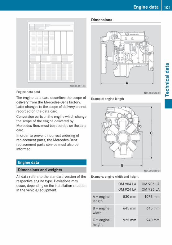
Engine data card
The engine data card describes the scope ofdelivery from the Mercedes-Benz factory.Later changes to the scope of delivery are notrecorded on the data card.Conversion parts on the engine which changethe scope of the engine delivered byMercedes-Benz must be recorded on the datacard.In order to prevent incorrect ordering ofreplacement parts, the Mercedes-Benzreplacement parts service must also beinformed.
Engine data
Dimensions and weightsAll data refers to the standard version of therespective engine type. Deviations mayoccur, depending on the installation situationin the vehicle/equipment.
Dimensions
Example: engine length
Example: engine width and height
OM 904 LAOM 924 LA
OM 906 LAOM 926 LA
A = enginelength
830 mm 1078 mm
B = enginewidth
645 mm 645 mm
C = engineheight
925 mm 940 mm
Engine data 101
Tech
nica
l dat
a
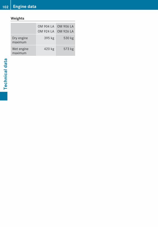
Weights
OM 904 LAOM 924 LA
OM 906 LAOM 926 LA
Dry enginemaximum
395 kg 530 kg
Wet enginemaximum
420 kg 573 kg
102 Engine dataTe
chni
cal d
ata
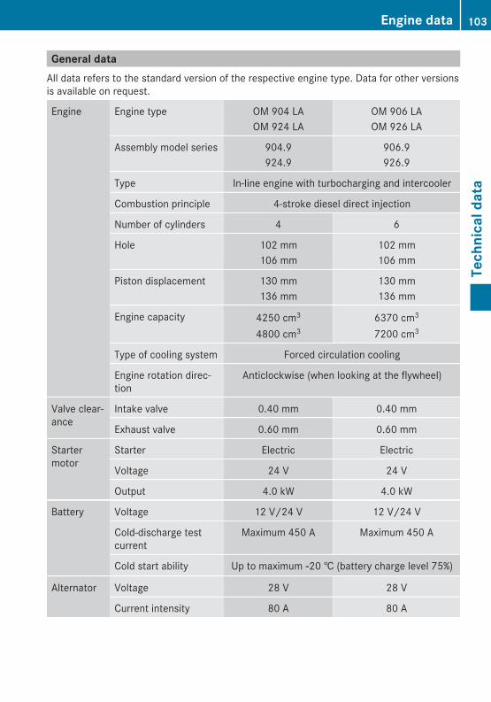
General dataAll data refers to the standard version of the respective engine type. Data for other versionsis available on request.
Engine Engine type OM 904 LAOM 924 LA
OM 906 LAOM 926 LA
Assembly model series 904.9924.9
906.9926.9
Type In-line engine with turbocharging and intercooler
Combustion principle 4-stroke diesel direct injection
Number of cylinders 4 6
Hole 102 mm106 mm
102 mm106 mm
Piston displacement 130 mm136 mm
130 mm136 mm
Engine capacity 4250 cm3
4800 cm36370 cm3
7200 cm3
Type of cooling system Forced circulation cooling
Engine rotation direc-tion
Anticlockwise (when looking at the flywheel)
Valve clear-ance
Intake valve 0.40 mm 0.40 mm
Exhaust valve 0.60 mm 0.60 mm
Startermotor
Starter Electric Electric
Voltage 24 V 24 V
Output 4.0 kW 4.0 kW
Battery Voltage 12 V/24 V 12 V/24 V
Cold-discharge testcurrent
Maximum 450 A Maximum 450 A
Cold start ability Up to maximum Ò20 † (battery charge level 75%)
Alternator Voltage 28 V 28 V
Current intensity 80 A 80 A
Engine data 103
Tech
nica
l dat
a
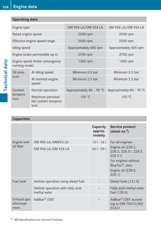
Operating data
Engine type OM 904 LA/OM 924 LA OM 906 LA/OM 926 LA
Rated engine speed 2200 rpm 2200 rpm
Effective engine speed range 2500 rpm 2500 rpm
Idling speed Approximately 600 rpm Approximately 600 rpm
Engine brake permissible up to 2700 rpm 2700 rpm
Engine speed limiter (emergencyrunning mode)
1300 rpm 1300 rpm
Oil pres-sure
At idling speed Minimum 0.5 bar Minimum 0.5 bar
At nominal enginespeed
Minimum 2.5 bar Minimum 2.5 bar
Coolanttempera-ture
Normal operation Approximately 80 – 95 † Approximately 80 – 95 †
Maximum permissi-ble coolant tempera-ture
100 † 100 †
Capacities
Capacityapprox-imately
Service product(sheet no.9)
Engine withoil filter
OM 904 LA/OM924 LA 13 l - 16 l For all engines:Engine oil (228.2,228.3, 228.31, 228.5,228.51)For engines withoutBlueTec®, also:Engine oil (228.0,228.1)
OM 906 LA/OM 926 LA 24 l - 29 l
Fuel tank Vehicle operation using diesel fuel – Diesel fuels (131.0)
Vehicle operation with fatty acidmethyl ester
– Fatty acid methyl esterfuel (135.0)
Exhaust gasaftertreat-ment
AdBlue®/DEF – AdBlue®/DEF accord-ing to DIN 70070/ISO22241
9 MB Specifications for Service Products.
104 Engine dataTe
chni
cal d
ata
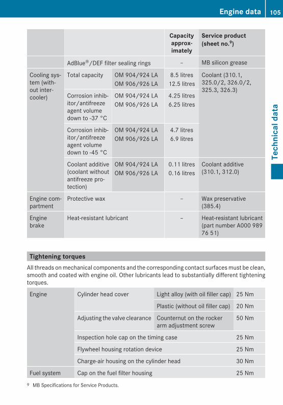
Capacityapprox-imately
Service product(sheet no.9)
AdBlue®/DEF filter sealing rings – MB silicon grease
Cooling sys-tem (with-out inter-cooler)
Total capacity OM 904/924 LAOM 906/926 LA
8.5 litres12.5 litres
Coolant (310.1,325.0/2, 326.0/2,325.3, 326.3)
Corrosion inhib-itor/antifreezeagent volumedown to -37 °C
OM 904/924 LAOM 906/926 LA
4.25 litres6.25 litres
Corrosion inhib-itor/antifreezeagent volumedown to -45 °C
OM 904/924 LAOM 906/926 LA
4.7 litres6.9 litres
Coolant additive(coolant withoutantifreeze pro-tection)
OM 904/924 LAOM 906/926 LA
0.11 litres0.16 litres
Coolant additive(310.1, 312.0)
Engine com-partment
Protective wax – Wax preservative(385.4)
Enginebrake
Heat-resistant lubricant – Heat-resistant lubricant(part number A000 98976 51)
Tightening torquesAll threads on mechanical components and the corresponding contact surfaces must be clean,smooth and coated with engine oil. Other lubricants lead to substantially different tighteningtorques.
Engine Cylinder head cover Light alloy (with oil filler cap) 25 Nm
Plastic (without oil filler cap) 20 Nm
Adjusting the valve clearance Counternut on the rockerarm adjustment screw
50 Nm
Inspection hole cap on the timing case 25 Nm
Flywheel housing rotation device 25 Nm
Charge-air housing on the cylinder head 30 Nm
Fuel system Cap on the fuel filter housing 25 Nm
9 MB Specifications for Service Products.
Engine data 105
Tech
nica
l dat
a
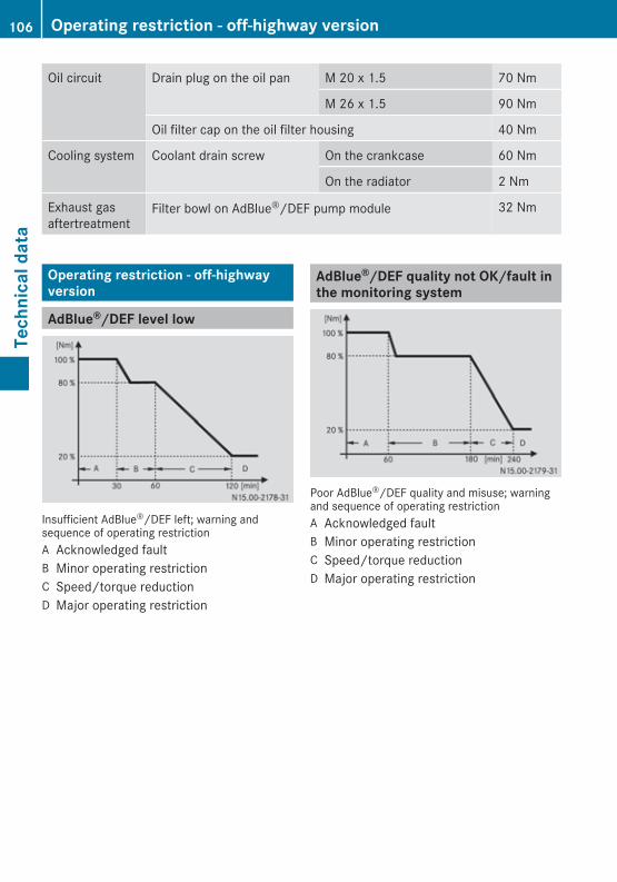
Oil circuit Drain plug on the oil pan M 20 x 1.5 70 Nm
M 26 x 1.5 90 Nm
Oil filter cap on the oil filter housing 40 Nm
Cooling system Coolant drain screw On the crankcase 60 Nm
On the radiator 2 Nm
Exhaust gasaftertreatment
Filter bowl on AdBlue®/DEF pump module 32 Nm
Operating restriction - off-highwayversion
AdBlue®/DEF level low
Insufficient AdBlue®/DEF left; warning andsequence of operating restrictionA Acknowledged faultB Minor operating restrictionC Speed/torque reductionD Major operating restriction
AdBlue®/DEF quality not OK/fault inthe monitoring system
Poor AdBlue®/DEF quality and misuse; warningand sequence of operating restrictionA Acknowledged faultB Minor operating restrictionC Speed/torque reductionD Major operating restriction
106 Operating restriction - off-highway versionTe
chni
cal d
ata
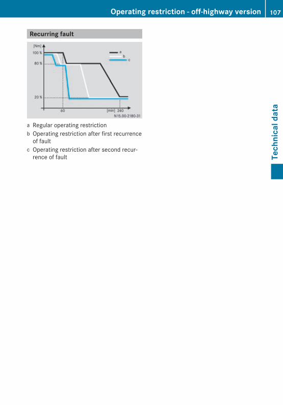
Recurring fault
a Regular operating restrictionb Operating restriction after first recurrence
of faultc Operating restriction after second recur-
rence of fault
Operating restriction - off-highway version 107
Tech
nica
l dat
a

108
ImprintInternet
You will find further information aboutMercedes-Benz engines, Daimler AG andTogum AG on the Internet at:www.mercedes-benz.comwww.daimler.comwww.mtu-online.com
Editorial office
You are welcome to forward any queries orsuggestions you might have regarding theseOperating Instructions to the technical docu-mentation team at the following address:Daimler AG, HPC: R822, D-70546 Stuttgart,Germany© Daimler AGNot to be reprinted, translated or otherwisereproduced, in whole or in part, without writ-ten permission.Printed in Germany
As at 04.05.2011

Order no. 6462 9820 02 Part no. 926 584 06 81 Edition A 06-11
É9265840681ÁËÍ9265840681