ohaus corporation 29 hanover road 07932-0900 manual.pdf · instruction manual industrial electronic...
TRANSCRIPT
Instruction Manual
INDUSTRIAL ELECTRONICWEIGHT INDICATORModel I10
Ohaus Corporation29 Hanover RoadFlorham Park NJ07932-0900
2
CLASSIFICATIONSCLASSIFICATIONSCLASSIFICATIONSCLASSIFICATIONSCLASSIFICATIONS
• National Institute of Standards and Technology Handbook 44 Class III and IIIL,certificate of conformance number 88-081A1
• Consumer and Corporate Affairs Canada Weights and Measures Act andRegulations general class. Notice of Approval number S.WA-4469
This device corresponds to requirements stipulated in 90/384/EEC andfeatures radio interference suppression in compliance with valid ECRegulation 89/336/EEC. Note: The displayed value may beadversely affected under extreme electro-magnetic influences, eg.when using a radio unit in the immediate vicinity of the device. Once the
interference has been rectified, the product can once again be used for its intendedpurpose. The device may have to be switched on again.
Cet appareil correspond aux exigences selon la norme 90/384/CEE et est déparasitéconformément à la directive de la CE 89/336/CEE en vigueur.Remarque: Dans des conditions d’influences électromagnétiques extêmes, parexemple en cas d’exploitation d’un appareil radio à proximité immédiate de I’appareil,la valeur d’affichage risque d’être influencée. Une fois que l’influence parasite estterminée, le produit peut être de nouveau utilisé de manière conforme aux prescrip-tions; le cas échéant, il est nécessaire de le remettre en marche.
Dieses Gerät entspricht den Anforderungen nach 90/384/EWG und ist funkentstörtentsprechend der geltenden EG-Richtlinie 89/336/EWG.Hinweis: Unter extremen elektromagnetischen Einflüssen z.B. bei Betreiben einesFunkgerätes in unmittelbarer Nähe des Gerätes kann eine Beeinflussung desAnzeigewertes verursacht werden. Nach Ende des Störeinflusses ist das Produktwieder bestimmungsgemäss benutzbar, ggfs. ist ein Wiedereinschalten erforderlich.
PREFACEPREFACEPREFACEPREFACEPREFACE
I 10 Indicators are software controlled devices with a host of user-programmablefeatures. Calibration and setting up features are easily accomplished through thesoftware using the front panel buttons and display.
WHAT TO READWHAT TO READWHAT TO READWHAT TO READWHAT TO READ
This manual explains how to use your I 10 properly and should be read beforeoperation.
• If your I 10 is part of an Ohaus Bench Scale setup, preprogrammed andcalibrated at the factory, or if it has already been installed and programmed foryou, Chapter 6 contains instructions on weighing, parts counting and using theinterface for printing.
• If you are an installer, Chapter 1 contains instructions for unpacking andinstalling the I 10.
• To program and calibrate the I 10 for a particular application, refer to Chapters2, 3, 4 and 5.
TABLE OF CONTENTSTABLE OF CONTENTSTABLE OF CONTENTSTABLE OF CONTENTSTABLE OF CONTENTS
Chapter 1 : InstallationChapter 1 : InstallationChapter 1 : InstallationChapter 1 : InstallationChapter 1 : Installation 6 6 6 6 6
Unpacking .......................................................................................... 7
Assembly ............................................................................................ 8
Rear Cover Removal ...................................................................... 8Load Receiver Connections ........................................................... 10Power Options ................................................................................ 11RS232 Cable .................................................................................. 12Internal Switch Functions ............................................................... 13 Memory Mode Enabled ................................................................ 13
Sealing and Mounting ........................................................................ 14
Turning the I 10 ON ........................................................................... 15
Front Panel Button Functions ............................................................ 16
Chapter 2: Setup ModeChapter 2: Setup ModeChapter 2: Setup ModeChapter 2: Setup ModeChapter 2: Setup Mode 1717171717
Setup Mode and the I 10 Menu Structure ......................................... 18
Chapter 3: Setting Program ConstantsChapter 3: Setting Program ConstantsChapter 3: Setting Program ConstantsChapter 3: Setting Program ConstantsChapter 3: Setting Program Constants 2020202020
Using the Program Constants Menu .................................................. 21
Legal For Trade.................................................................................. 23
Auto-Zero Tracking ............................................................................ 24
Zero .................................................................................................... 25
Calibration Unit .................................................................................. 26
Decimal Point Position ....................................................................... 27
Graduations ........................................................................................ 28
Full Scale Point .................................................................................. 29
Calibration Point ................................................................................. 30
Chapter 4: Setting Program OptionsChapter 4: Setting Program OptionsChapter 4: Setting Program OptionsChapter 4: Setting Program OptionsChapter 4: Setting Program Options 3232323232
Averaging Level ................................................................................. 33
Unit Selection ..................................................................................... 34
Custom Units .................................................................................. 35Parts Counting Error Level ............................................................. 37
Auto Shut-off Timer and RS232 Parameters ..................................... 39
Chapter 5: CalibrationChapter 5: CalibrationChapter 5: CalibrationChapter 5: CalibrationChapter 5: Calibration 4444444444
Gain Jumper ....................................................................................... 45
Linearization Switch ........................................................................... 45
Calibration Procedure ........................................................................ 46
Chapter 6: Weighing, Parts Counting and PrintingChapter 6: Weighing, Parts Counting and PrintingChapter 6: Weighing, Parts Counting and PrintingChapter 6: Weighing, Parts Counting and PrintingChapter 6: Weighing, Parts Counting and Printing 4848484848
Selecting a Weighing Unit or Parts Counting ..................................... 49
Weighing ............................................................................................ 49
Taring ................................................................................................. 49
Parts Counting ................................................................................... 51
Printing ............................................................................................... 53
Chapter 7: RS232 InterfaceChapter 7: RS232 InterfaceChapter 7: RS232 InterfaceChapter 7: RS232 InterfaceChapter 7: RS232 Interface 5454545454
Hardware ............................................................................................ 55
Output Formats .................................................................................. 55
RS232 Commands ............................................................................. 55
Chapter 8: Legal For Trade SealingChapter 8: Legal For Trade SealingChapter 8: Legal For Trade SealingChapter 8: Legal For Trade SealingChapter 8: Legal For Trade Sealing 5858585858
Setup and Calibration Restrictions .................................................... 59
Labeling .............................................................................................. 59
Sealing ............................................................................................... 59
Chapter 9: TroubleshootingChapter 9: TroubleshootingChapter 9: TroubleshootingChapter 9: TroubleshootingChapter 9: Troubleshooting 6262626262
Troubleshooting Chart ....................................................................... 63
Error Messages .................................................................................. 65
Care and Maintenance ....................................................................... 66
Service Information ............................................................................ 66
Chapter 10: Specifications, Replacement Parts and AccessoriesChapter 10: Specifications, Replacement Parts and AccessoriesChapter 10: Specifications, Replacement Parts and AccessoriesChapter 10: Specifications, Replacement Parts and AccessoriesChapter 10: Specifications, Replacement Parts and Accessories 6767676767
Specifications ..................................................................................... 68
Replacement Parts ............................................................................. 69
Accessories ........................................................................................ 69
Appendix 1: Common Custom Unit ConversionsAppendix 1: Common Custom Unit ConversionsAppendix 1: Common Custom Unit ConversionsAppendix 1: Common Custom Unit ConversionsAppendix 1: Common Custom Unit Conversions 7070707070
6
Chapter 1:Chapter 1:Chapter 1:Chapter 1:Chapter 1:InstallationInstallationInstallationInstallationInstallation
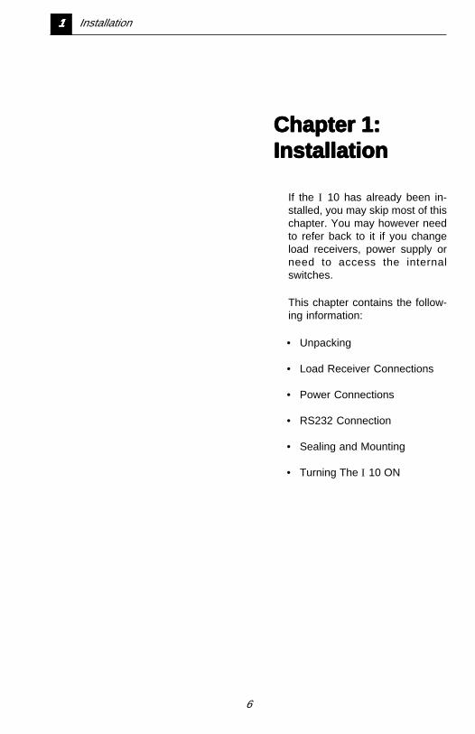
If the I 10 has already been in-stalled, you may skip most of thischapter. You may however needto refer back to it if you changeload receivers, power supply orneed to access the internalswitches.
This chapter contains the follow-ing information:
• Unpacking
• Load Receiver Connections
• Power Connections
• RS232 Connection
• Sealing and Mounting
• Turning The I 10 ON
11111 Installation
7
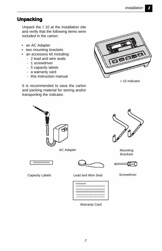
UnpackingUnpackingUnpackingUnpackingUnpacking
Unpack the I 10 at the installation siteand verify that the following items wereincluded in the carton:
• an AC Adapter• two mounting brackets• an accessory kit including:
- 2 lead and wire seals- 1 screwdriver- 5 capacity labels- a warranty card- this instruction manual
It is recommended to save the cartonand packing material for storing and/ortransporting the indicator.
I 10 Indicator
AC Adapter
Capacity Labels Lead and Wire Seal
Warranty Card
MountingBrackets
Screwdriver
Installation 11111
8
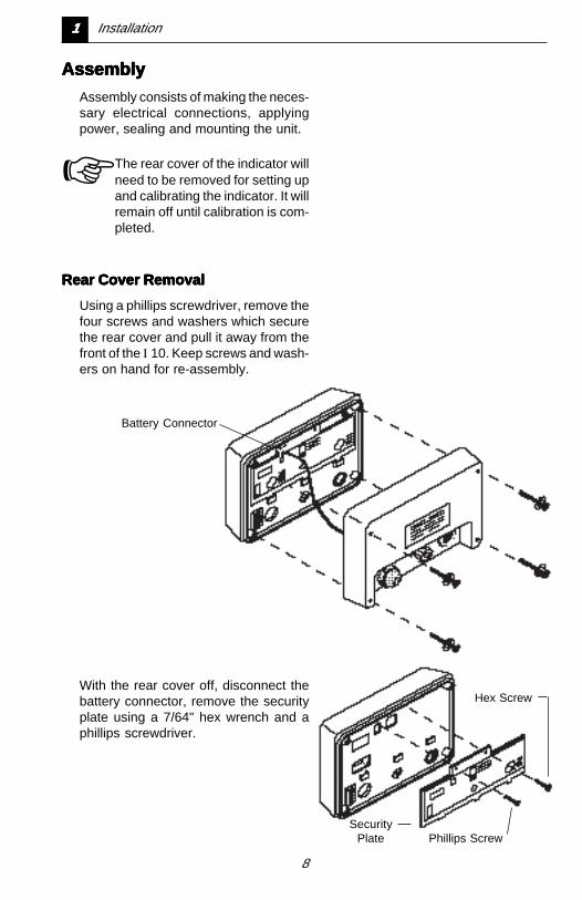
AssemblyAssemblyAssemblyAssemblyAssembly
Assembly consists of making the neces-sary electrical connections, applyingpower, sealing and mounting the unit.
☞ The rear cover of the indicator willneed to be removed for setting upand calibrating the indicator. It willremain off until calibration is com-pleted.
Rear Cover RemovalRear Cover RemovalRear Cover RemovalRear Cover RemovalRear Cover Removal
Using a phillips screwdriver, remove thefour screws and washers which securethe rear cover and pull it away from thefront of the I 10. Keep screws and wash-ers on hand for re-assembly.
With the rear cover off, disconnect thebattery connector, remove the securityplate using a 7/64" hex wrench and aphillips screwdriver.
Hex Screw
SecurityPlate Phillips Screw
Battery Connector
11111 Installation
9
Installation 11111
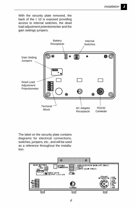
With the security plate removed, theback of the I 10 is exposed providingaccess to internal switches, the deadload adjustment potentiomenter and thegain settings jumpers.
The label on the security plate containsdiagrams for electrical connections,switches, jumpers, etc., and will be usedas a reference throughout the installa-tion.
InternalSwitches
TerminalBlock
Dead LoadAdjustmentPotentiometer
Gain SettingJumpers
BatteryReceptacle
AC AdapterReceptacle
RS232Connector
10
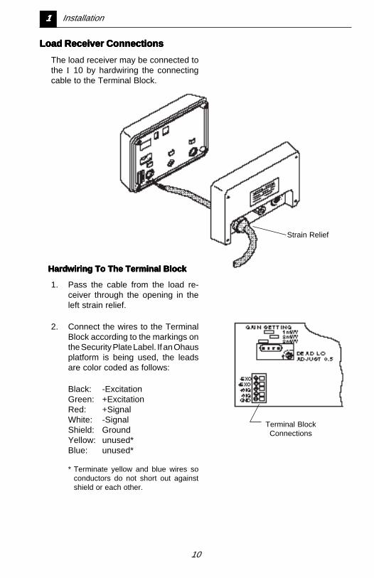
Load Receiver ConnectionsLoad Receiver ConnectionsLoad Receiver ConnectionsLoad Receiver ConnectionsLoad Receiver Connections
The load receiver may be connected tothe I 10 by hardwiring the connectingcable to the Terminal Block.
Terminal BlockConnections
Strain Relief
Hardwiring To The Terminal BlockHardwiring To The Terminal BlockHardwiring To The Terminal BlockHardwiring To The Terminal BlockHardwiring To The Terminal Block
1. Pass the cable from the load re-ceiver through the opening in theleft strain relief.
2. Connect the wires to the TerminalBlock according to the markings onthe Security Plate Label. If an Ohausplatform is being used, the leadsare color coded as follows:
Black: -ExcitationGreen: +ExcitationRed: +SignalWhite: -SignalShield: GroundYellow: unused*Blue: unused*
* Terminate yellow and blue wires soconductors do not short out againstshield or each other.
11111 Installation
11
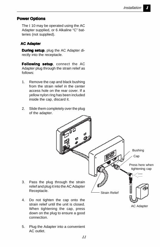
Power OptionsPower OptionsPower OptionsPower OptionsPower Options
The I 10 may be operated using the ACAdapter supplied, or 6 Alkaline “C” bat-teries (not supplied).
AC AdapterAC AdapterAC AdapterAC AdapterAC Adapter
During setupDuring setupDuring setupDuring setupDuring setup , plug the AC Adapter di-rectly into the receptacle.
Following setupFollowing setupFollowing setupFollowing setupFollowing setup , connect the ACAdapter plug through the strain relief asfollows:
1. Remove the cap and black bushingfrom the strain relief in the centeraccess hole on the rear cover. If ayellow nylon ring has been includedinside the cap, discard it.
2. Slide them completely over the plugof the adapter.
AC Adapter
3. Pass the plug through the strainrelief and plug it into the AC AdapterReceptacle.
4. Do not tighten the cap onto thestrain relief until the unit is closed.When tightening the cap, pressdown on the plug to ensure a goodconnection.
5. Plug the Adapter into a convenientAC outlet.
Strain Relief
Bushing
Cap
Press here whentightening cap
Installation 11111
12
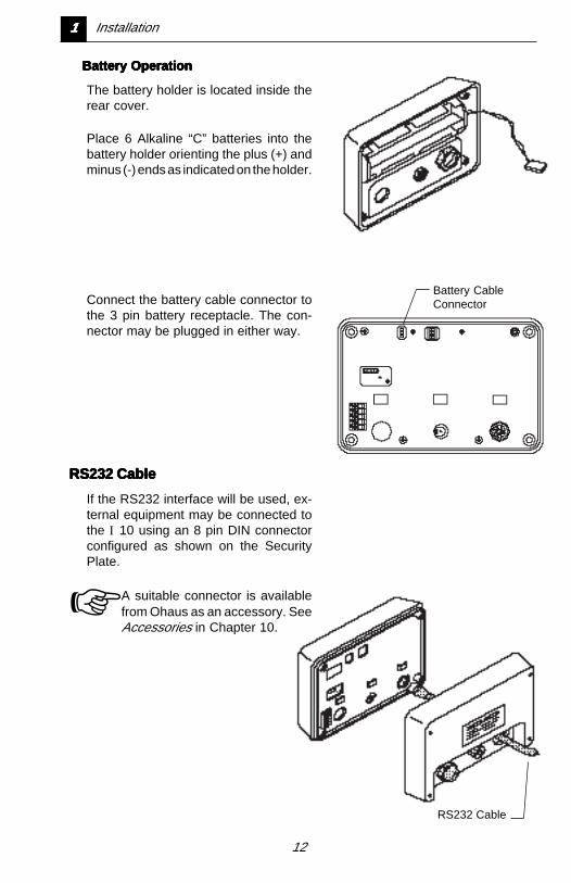
Battery OperationBattery OperationBattery OperationBattery OperationBattery Operation
The battery holder is located inside therear cover.
Place 6 Alkaline “C” batteries into thebattery holder orienting the plus (+) andminus (-) ends as indicated on the holder.
RS232 Cable
RS232 CableRS232 CableRS232 CableRS232 CableRS232 Cable
If the RS232 interface will be used, ex-ternal equipment may be connected tothe I 10 using an 8 pin DIN connectorconfigured as shown on the SecurityPlate.
☞ A suitable connector is availablefrom Ohaus as an accessory. SeeAccessories in Chapter 10.
Connect the battery cable connector tothe 3 pin battery receptacle. The con-nector may be plugged in either way.
Battery CableConnector
11111 Installation
13
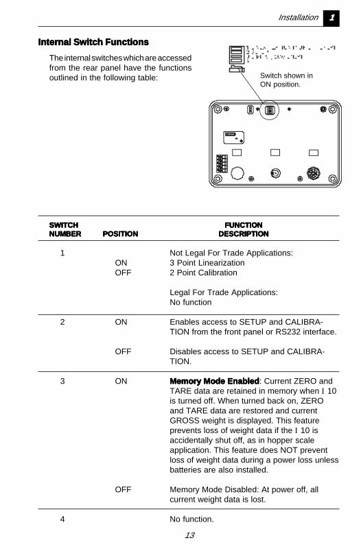
SWITCHSWITCHSWITCHSWITCHSWITCH FUNCTIONFUNCTIONFUNCTIONFUNCTIONFUNCTIONNUMBERNUMBERNUMBERNUMBERNUMBER POSITIONPOSITIONPOSITIONPOSITIONPOSITION DESCRIPTIONDESCRIPTIONDESCRIPTIONDESCRIPTIONDESCRIPTION
1 Not Legal For Trade Applications:ON 3 Point LinearizationOFF 2 Point Calibration
Legal For Trade Applications:No function
2 ON Enables access to SETUP and CALIBRA-TION from the front panel or RS232 interface.
OFF Disables access to SETUP and CALIBRA-TION.
3 ON Memory Mode EnabledMemory Mode EnabledMemory Mode EnabledMemory Mode EnabledMemory Mode Enabled : Current ZERO andTARE data are retained in memory when I 10is turned off. When turned back on, ZEROand TARE data are restored and currentGROSS weight is displayed. This featureprevents loss of weight data if the I 10 isaccidentally shut off, as in hopper scaleapplication. This feature does NOT preventloss of weight data during a power loss unlessbatteries are also installed.
OFF Memory Mode Disabled: At power off, allcurrent weight data is lost.
4 No function.
Internal Switch FunctionsInternal Switch FunctionsInternal Switch FunctionsInternal Switch FunctionsInternal Switch Functions
The internal switches which are accessedfrom the rear panel have the functionsoutlined in the following table: Switch shown in
ON position.
Installation 11111
14
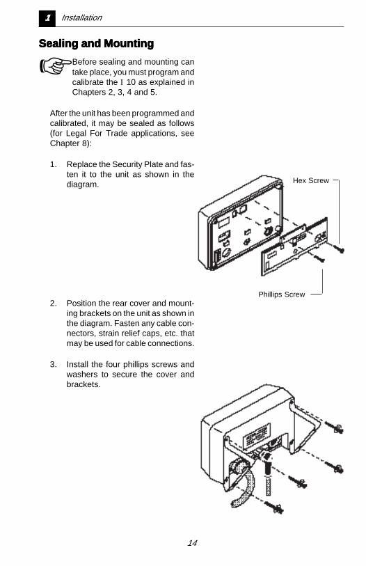
Sealing and MountingSealing and MountingSealing and MountingSealing and MountingSealing and Mounting
☞ Before sealing and mounting cantake place, you must program andcalibrate the I 10 as explained inChapters 2, 3, 4 and 5.
After the unit has been programmed andcalibrated, it may be sealed as follows(for Legal For Trade applications, seeChapter 8):
1. Replace the Security Plate and fas-ten it to the unit as shown in thediagram.
2. Position the rear cover and mount-ing brackets on the unit as shown inthe diagram. Fasten any cable con-nectors, strain relief caps, etc. thatmay be used for cable connections.
3. Install the four phillips screws andwashers to secure the cover andbrackets.
Hex Screw
Phillips Screw
11111 Installation

15
Lights when scale is at centerof zero
Indicates low battery condi-tion
Indicates negative value
Lights to indicate currentweighing unit is pounds
Lights to indicate currentweighing unit is kilograms
Lights to indicate currentweighing unit is custom unit
Indicates I 10 is in partscounting mode
Indicates displayed value isa percentage
Lights next to “GROSS” whengross weight is displayed
Lights next to “NET” whennet weight is displayed
Turning The Turning The Turning The Turning The Turning The IIIII 10 ON 10 ON 10 ON 10 ON 10 ON
After all connections have been made,turn the I 10 ON by pressing the ON/ZERO button on the front panel.
When first turned on, all display seg-ments and enabled indicators will lightbriefly, and then clear.
Display Indicator FunctionsDisplay Indicator FunctionsDisplay Indicator FunctionsDisplay Indicator FunctionsDisplay Indicator Functions
Installation 11111
16
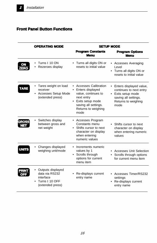
• Turns I 10 ON• Rezeroes display
• Tares weight on loadreceiver
• Accesses Setup Mode(extended press)
• Switches displaybetween gross andnet weight
• Changes displayedweighing unit/mode
• Outputs displayeddata via RS232interface
• Turns I 10 OFF(extended press)
Program ConstantsProgram ConstantsProgram ConstantsProgram ConstantsProgram ConstantsMenuMenuMenuMenuMenu
• Turns all digits ON orresets to initial value
• Accesses Calibration• Enters displayed
value, continues tonext entry
• Exits setup modesaving all settings.Returns to weighingmode
• Accesses ProgramConstants menu
• Shifts cursor to nextcharacter on displaywhen enteringnumeric values
• Increments numericvalues by 1
• Scrolls throughoptions for currentmenu item
• Re-displays currententry name
Program OptionsProgram OptionsProgram OptionsProgram OptionsProgram OptionsMenuMenuMenuMenuMenu
• Accesses AveragingLevel
• Turns all digits ON orresets to initial value
• Enters displayed value,continues to next entry
• Exits setup modesaving all settings.Returns to weighingmode
• Shifts cursor to nextcharacter on displaywhen entering numericvalues
• Accesses Unit Selection• Scrolls through options
for current menu item
• Accesses Timer/RS232settings
• Re-displays currententry name
PRINTPRINTPRINTPRINTPRINTOFFOFFOFFOFFOFF
UNITSUNITSUNITSUNITSUNITS
GROSSGROSSGROSSGROSSGROSSNETNETNETNETNET
TARETARETARETARETARE
ONONONONONZEROZEROZEROZEROZERO
OPERATING MODEOPERATING MODEOPERATING MODEOPERATING MODEOPERATING MODE SETUP MODESETUP MODESETUP MODESETUP MODESETUP MODE
Front Panel Button FunctionsFront Panel Button FunctionsFront Panel Button FunctionsFront Panel Button FunctionsFront Panel Button Functions
11111 Installation
17
Setup Mode 22222
Chapter 2:Chapter 2:Chapter 2:Chapter 2:Chapter 2:Setup ModeSetup ModeSetup ModeSetup ModeSetup Mode
The Setup mode enables you toprogram and calibrate the I 10using the front panel buttons andthe display.
When you first install the I 10, youmust use the Setup mode to enterinformation about the load receiverbeing used and to perform calibra-tion. You may also use it to pro-gram options that will customizethe I 10 for your specific weighingrequirements.
This Chapter explains how to ac-cess and use the Setup mode.

18
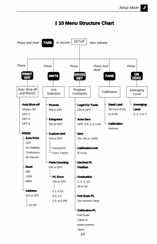
Setup Mode and the Setup Mode and the Setup Mode and the Setup Mode and the Setup Mode and the IIIII 10 10 10 10 10Menu StructureMenu StructureMenu StructureMenu StructureMenu Structure
Programmable features of the I 10 arecontained in “menus” which are accessedin the Setup mode. The chart on page2-3 shows how these menus are struc-tured.
To access the Setup mode:To access the Setup mode:To access the Setup mode:To access the Setup mode:To access the Setup mode:
Switch 2 on the rear panel must be in theON position.
press and hold until “SEtUP” is
displayed, then release it.
To access a menu:To access a menu:To access a menu:To access a menu:To access a menu:
Refer to the chart on page 2-3 for theproper front panel button to press for themenu you wish to access. Chapters 3, 4and 5 contain information on using eachof the menus shown in the chart.
Initial SetupInitial SetupInitial SetupInitial SetupInitial Setup
For initial setup of the I 10, you must gothrough the Program Constants menuand Calibration. All other menus areoptional.
Locking Out Setup ModeLocking Out Setup ModeLocking Out Setup ModeLocking Out Setup ModeLocking Out Setup Mode
When you are finished with the Setupmode, Switch 2 can be set to OFF toprevent unauthorized programming orcalibration.
Switch shown inON position.
Setup Mode 22222
19
Legal For TradeLegal For TradeLegal For TradeLegal For TradeLegal For Trade
ON or OFF
Auto-ZeroAuto-ZeroAuto-ZeroAuto-ZeroAuto-Zero
OFF, 0.6, 1 or 3 div.
ZeroZeroZeroZeroZero
2%, 4% or 100%
Calibration UnitCalibration UnitCalibration UnitCalibration UnitCalibration Unit
lb or kg
Decimal Pt.Decimal Pt.Decimal Pt.Decimal Pt.Decimal Pt.
PositionPositionPositionPositionPosition
GraduationGraduationGraduationGraduationGraduation
1, 2, 5, 10,
20 or 50
Full Scale Pt.Full Scale Pt.Full Scale Pt.Full Scale Pt.Full Scale Pt.
Set numeric value
Calibration Pt.Calibration Pt.Calibration Pt.Calibration Pt.Calibration Pt.
Full Scale
Value or
enter numeric
value
Auto Shut-offAuto Shut-offAuto Shut-offAuto Shut-offAuto Shut-off
Always ON
OFF-2
OFF-5
OFF-9
RS232RS232RS232RS232RS232
Auto PrintAuto PrintAuto PrintAuto PrintAuto Print
OFF
On Stability
Continuous
@ Interval
BaudBaudBaudBaudBaud
300
1200
9600
AddressAddressAddressAddressAddress
ON or OFF
01-99
Auto Shut-offand RS232
UnitSelection
ProgramConstants
PoundsPoundsPoundsPoundsPounds
ON or OFF
KilogramsKilogramsKilogramsKilogramsKilograms
ON or OFF
Custom UnitCustom UnitCustom UnitCustom UnitCustom Unit
ON or OFF
Decimal Pt.
Conv. Factor
Parts CountingParts CountingParts CountingParts CountingParts Counting
ON or OFF
PC ErrorPC ErrorPC ErrorPC ErrorPC Error
ON or OFF
0.1, 0.25,
0.5, 1.0,
2.5, or 5.0%
Calibration
Dead LoadDead LoadDead LoadDead LoadDead Load
Set from 0.5%
to 3.0%
CalibrationCalibrationCalibrationCalibrationCalibration
Perform
AveragingLevel
AveragingAveragingAveragingAveragingAveraging
LevelLevelLevelLevelLevel
0, 1, 2 or 3
Press and Hold
PRINTPRINTPRINTPRINTPRINTOFFOFFOFFOFFOFF UNITSUNITSUNITSUNITSUNITS GROSSGROSSGROSSGROSSGROSS
NETNETNETNETNETTARETARETARETARETARE ONONONONON
ZEROZEROZEROZEROZERO
Press Press Press Press andHold
Press
TARETARETARETARETARE to access SETUP then release.
IIIII 10 Menu Structure Chart 10 Menu Structure Chart 10 Menu Structure Chart 10 Menu Structure Chart 10 Menu Structure Chart
Setup Mode 22222
20
33333 Setting Program Constants
Chapter 3:Chapter 3:Chapter 3:Chapter 3:Chapter 3:Setting PrSetting PrSetting PrSetting PrSetting Pr ogramogramogramogramogramConstantsConstantsConstantsConstantsConstants
Program Constants configure theI 10 for the load receiver beingused and for Legal for Trade re-quirements if needed.
The Program Constants menu isaccessed from the Setup mode.When the I 10 is setup for the firsttime, it is recommended to gothrough all parameters in themenu. Once it has been setup,you can return to the menu tochange individual parameter set-tings.
☞ Since the parameters in thismenu define the load re-ceiver, the I 10 must be reca-librated when any of theseparameters are changed.
21
Using The ProgramUsing The ProgramUsing The ProgramUsing The ProgramUsing The ProgramConstants MenuConstants MenuConstants MenuConstants MenuConstants Menu
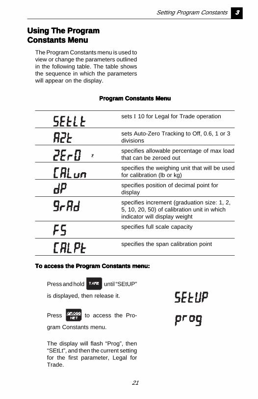
The Program Constants menu is used toview or change the parameters outlinedin the following table. The table showsthe sequence in which the parameterswill appear on the display.
Program Constants MenuProgram Constants MenuProgram Constants MenuProgram Constants MenuProgram Constants Menu
sets I 10 for Legal for Trade operation
sets Auto-Zero Tracking to Off, 0.6, 1 or 3divisions
specifies allowable percentage of max loadthat can be zeroed out
specifies the weighing unit that will be usedfor calibration (lb or kg)
specifies position of decimal point fordisplay
specifies increment (graduation size: 1, 2,5, 10, 20, 50) of calibration unit in whichindicator will display weight
specifies full scale capacity
specifies the span calibration point
To access the Program Constants menu:To access the Program Constants menu:To access the Program Constants menu:To access the Program Constants menu:To access the Program Constants menu:
Press and hold until “SEtUP”
is displayed, then release it.
Press to access the Pro-
gram Constants menu.
The display will flash “Prog”, then“SEtLt”, and then the current settingfor the first parameter, Legal forTrade.
Setting Program Constants 33333
22
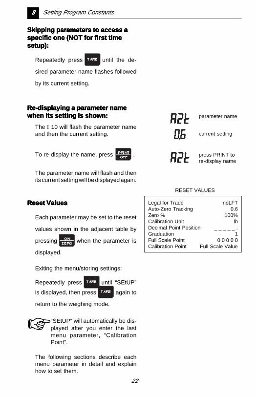
Skipping parameters to access aSkipping parameters to access aSkipping parameters to access aSkipping parameters to access aSkipping parameters to access aspecific one (NOT for first timespecific one (NOT for first timespecific one (NOT for first timespecific one (NOT for first timespecific one (NOT for first timesetup):setup):setup):setup):setup):
Repeatedly press until the de-
sired parameter name flashes followed
by its current setting.
Re-displaying a parameter nameRe-displaying a parameter nameRe-displaying a parameter nameRe-displaying a parameter nameRe-displaying a parameter namewhen its setting is shown:when its setting is shown:when its setting is shown:when its setting is shown:when its setting is shown:
The I 10 will flash the parameter nameand then the current setting.
To re-display the name, press .
The parameter name will flash and thenits current setting will be displayed again.
Reset ValuesReset ValuesReset ValuesReset ValuesReset Values
Each parameter may be set to the reset
values shown in the adjacent table by
pressing when the parameter is
displayed.
Exiting the menu/storing settings:
Repeatedly press until “SEtUP”
is displayed, then press again to
return to the weighing mode.
☞ “SEtUP” will automatically be dis-played after you enter the lastmenu parameter, “CalibrationPoint”.
The following sections describe eachmenu parameter in detail and explainhow to set them.
parameter name
current setting
press PRINT tore-display name
RESET VALUES
Legal for Trade noLFTAuto-Zero Tracking 0.6Zero % 100%Calibration Unit lbDecimal Point Position _ _ _ _ _ .Graduation 1Full Scale Point 0 0 0 0 0Calibration Point Full Scale Value
33333 Setting Program Constants
23
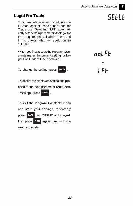
Legal For TradeLegal For TradeLegal For TradeLegal For TradeLegal For Trade
This parameter is used to configure theI 10 for Legal for Trade or non Legal forTrade use. Selecting “LFT” automati-cally sets certain parameters for legal fortrade requirements, disables others, andlimits overall display resolution to1:10,000.
When you first access the Program Con-stants menu, the current setting for Le-gal For Trade will be displayed.
To change the setting, press .
To accept the displayed setting and pro-
ceed to the next parameter (Auto-Zero
Tracking), press .
To exit the Program Constants menu
and store your settings, repeatedly
press until “SEtUP” is displayed,
then press again to return to the
weighing mode.
or
Setting Program Constants 33333
24
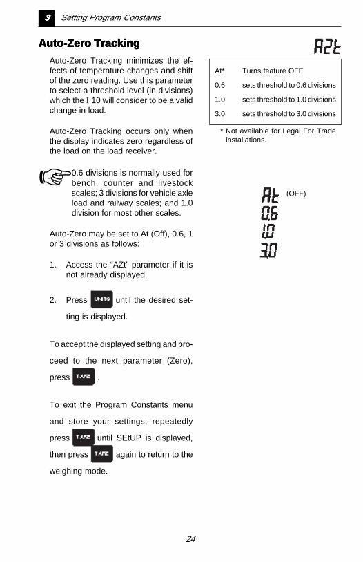
Auto-Zero TrackingAuto-Zero TrackingAuto-Zero TrackingAuto-Zero TrackingAuto-Zero Tracking
Auto-Zero Tracking minimizes the ef-fects of temperature changes and shiftof the zero reading. Use this parameterto select a threshold level (in divisions)which the I 10 will consider to be a validchange in load.
Auto-Zero Tracking occurs only whenthe display indicates zero regardless ofthe load on the load receiver.
☞ 0.6 divisions is normally used forbench, counter and livestockscales; 3 divisions for vehicle axleload and railway scales; and 1.0division for most other scales.
Auto-Zero may be set to At (Off), 0.6, 1or 3 divisions as follows:
1. Access the “AZt” parameter if it isnot already displayed.
2. Press until the desired set-
ting is displayed.
To accept the displayed setting and pro-
ceed to the next parameter (Zero),
press .
To exit the Program Constants menu
and store your settings, repeatedly
press until SEtUP is displayed,
then press again to return to the
weighing mode.
At* Turns feature OFF
0.6 sets threshold to 0.6 divisions
1.0 sets threshold to 1.0 divisions
3.0 sets threshold to 3.0 divisions
* Not available for Legal For Tradeinstallations.
(OFF)
33333 Setting Program Constants
25
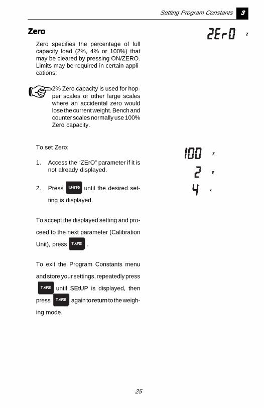
ZeroZeroZeroZeroZero
Zero specifies the percentage of fullcapacity load (2%, 4% or 100%) thatmay be cleared by pressing ON/ZERO.Limits may be required in certain appli-cations:
☞ 2% Zero capacity is used for hop-per scales or other large scaleswhere an accidental zero wouldlose the current weight. Bench andcounter scales normally use 100%Zero capacity.
To set Zero:
1. Access the “ZErO” parameter if it isnot already displayed.
2. Press until the desired set-
ting is displayed.
To accept the displayed setting and pro-
ceed to the next parameter (Calibration
Unit), press .
To exit the Program Constants menu
and store your settings, repeatedly press
until SEtUP is displayed, then
press again to return to the weigh-
ing mode.
Setting Program Constants 33333
26
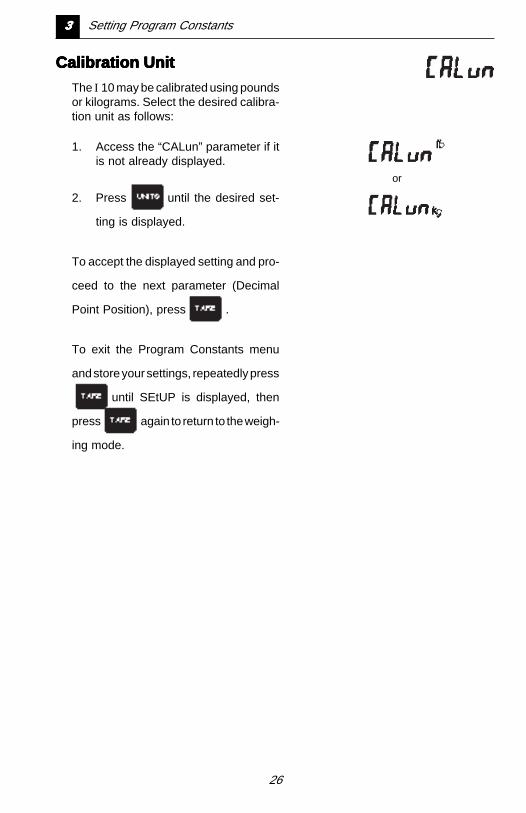
Calibration UnitCalibration UnitCalibration UnitCalibration UnitCalibration Unit
The I 10 may be calibrated using poundsor kilograms. Select the desired calibra-tion unit as follows:
1. Access the “CALun” parameter if itis not already displayed.
2. Press until the desired set-
ting is displayed.
To accept the displayed setting and pro-
ceed to the next parameter (Decimal
Point Position), press .
To exit the Program Constants menu
and store your settings, repeatedly press
until SEtUP is displayed, then
press again to return to the weigh-
ing mode.
or
33333 Setting Program Constants
27
Decimal Point PositionDecimal Point PositionDecimal Point PositionDecimal Point PositionDecimal Point Position
You may set the position of the decimalpoint for displayed weight readings asfollows:
1. Access the “dP” parameter if it is notalready displayed.
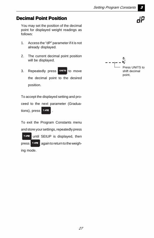
2. The current decimal point positionwill be displayed.
3. Repeatedly press to move
the decimal point to the desired
position.
To accept the displayed setting and pro-
ceed to the next parameter (Gradua-
tions), press .
To exit the Program Constants menu
and store your settings, repeatedly press
until SEtUP is displayed, then
press again to return to the weigh-
ing mode.
Press UNITS toshift decimalpoint.
Setting Program Constants 33333
28
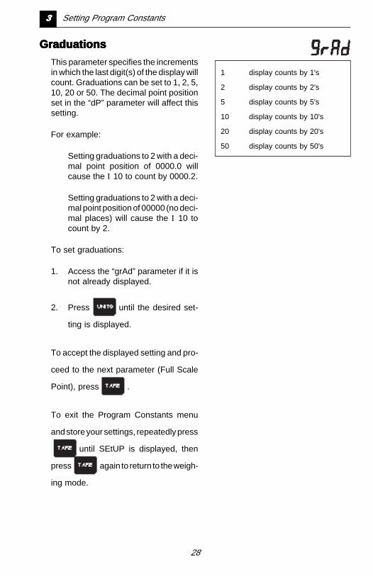
GraduationsGraduationsGraduationsGraduationsGraduations
This parameter specifies the incrementsin which the last digit(s) of the display willcount. Graduations can be set to 1, 2, 5,10, 20 or 50. The decimal point positionset in the “dP” parameter will affect thissetting.
For example:
Setting graduations to 2 with a deci-mal point position of 0000.0 willcause the I 10 to count by 0000.2.
Setting graduations to 2 with a deci-mal point position of 00000 (no deci-mal places) will cause the I 10 tocount by 2.
To set graduations:
1. Access the “grAd” parameter if it isnot already displayed.
2. Press until the desired set-
ting is displayed.
To accept the displayed setting and pro-
ceed to the next parameter (Full Scale
Point), press .
To exit the Program Constants menu
and store your settings, repeatedly press
until SEtUP is displayed, then
press again to return to the weigh-
ing mode.
1 display counts by 1's
2 display counts by 2's
5 display counts by 5's
10 display counts by 10's
20 display counts by 20's
50 display counts by 50's
33333 Setting Program Constants
29
Full Scale PointFull Scale PointFull Scale PointFull Scale PointFull Scale Point
The maximum capacity of the load re-ceiver is entered for Full Scale Pointusing the same weighing unit selectedfor the Calibration Unit.
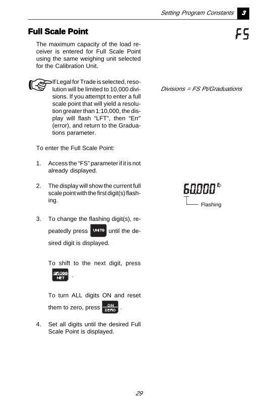
☞ If Legal for Trade is selected, reso-lution will be limited to 10,000 divi-sions. If you attempt to enter a fullscale point that will yield a resolu-tion greater than 1:10,000, the dis-play will flash “LFT”, then “Err”(error), and return to the Gradua-tions parameter.
To enter the Full Scale Point:
1. Access the “FS” parameter if it is notalready displayed.
2. The display will show the current fullscale point with the first digit(s) flash-ing.
3. To change the flashing digit(s), re-
peatedly press until the de-
sired digit is displayed.
To shift to the next digit, press
.
To turn ALL digits ON and reset
them to zero, press .
4. Set all digits until the desired FullScale Point is displayed.
Divisions = FS Pt/Graduations
Flashing
Setting Program Constants 33333
30
To accept the displayed setting and pro-
ceed to the next parameter (Calibration
Point), press .
To exit the Program Constants menu
and store your settings, repeatedly press
until SEtUP is displayed, then
press again to return to the weigh-
ing mode.
Calibration PointCalibration PointCalibration PointCalibration PointCalibration Point
The calibration point is the weight valuethat will be used to calibrate the I 10. Itcan be any value from 10% to 100% ofthe Full Scale Point.
☞ If Linearization is enabled (inter-nal Switch 1is ON), the calibrationpoint must be at least 75% FullScale Point.
To enter the calibration point:
1. Access the “CALPt” parameter if itis not already displayed.
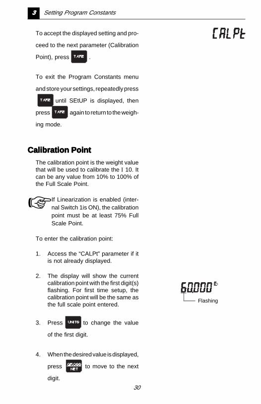
2. The display will show the currentcalibration point with the first digit(s)flashing. For first time setup, thecalibration point will be the same asthe full scale point entered.
3. Press to change the value
of the first digit.
4. When the desired value is displayed,
press to move to the next
digit.
Flashing
33333 Setting Program Constants
31
Setting Program Constants 33333
5. Set the value of all digits in the samemanner until the desired Calibra-tion Point is displayed.
☞ You may set the Calibration Point
equal to the Full Scale Point (if it is
not already) with one button by
pressing .
To exit the Program Constants menu
and store your settings, press and
SEtUP will be displayed.
Press again to return to the weigh-
ing mode.
32
Chapter 4:Chapter 4:Chapter 4:Chapter 4:Chapter 4:Setting PrSetting PrSetting PrSetting PrSetting Pr ogramogramogramogramogramOptionsOptionsOptionsOptionsOptions
Program Options are I 10 featuresthat you can customize for yourspecific requirements. These in-clude the weighing units you wishto use, averaging level for yourenvironment, RS232 configurationand the auto shut-off timer.
They are accessed from the Setupmode and arranged in threemenus:
• Averaging Level
• Unit Selection
• Auto Shut-Off Timer and RS232
Program Options may be changedat any time without having torecalibrate the I 10.
44444 Setting Program Options
33
Averaging LevelAveraging LevelAveraging LevelAveraging LevelAveraging Level
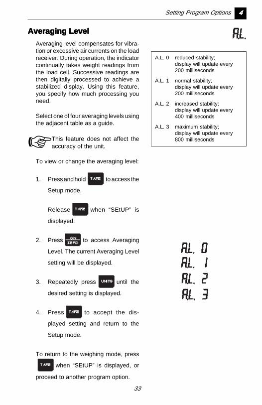
Averaging level compensates for vibra-tion or excessive air currents on the loadreceiver. During operation, the indicatorcontinually takes weight readings fromthe load cell. Successive readings arethen digitally processed to achieve astabilized display. Using this feature,you specify how much processing youneed.
Select one of four averaging levels usingthe adjacent table as a guide.
☞ This feature does not affect theaccuracy of the unit.
To view or change the averaging level:
1. Press and hold to access the
Setup mode.
Release when “SEtUP” is
displayed.
2. Press to access Averaging
Level. The current Averaging Level
setting will be displayed.
3. Repeatedly press until the
desired setting is displayed.
4. Press to accept the dis-
played setting and return to the
Setup mode.
To return to the weighing mode, press
when “SEtUP” is displayed, or
proceed to another program option.
A.L. 0 reduced stability;display will update every200 milliseconds
A.L. 1 normal stability;display will update every200 milliseconds
A.L. 2 increased stability;display will update every400 milliseconds
A.L. 3 maximum stability;display will update every800 milliseconds
Setting Program Options 44444
34
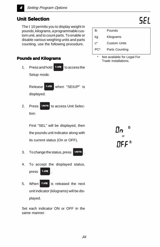
Unit SelectionUnit SelectionUnit SelectionUnit SelectionUnit Selection
The I 10 permits you to display weight inpounds, kilograms, a programmable cus-tom unit, and to count parts. To enable ordisable various weighing units and partscounting, use the following procedure.
Pounds and KilogramsPounds and KilogramsPounds and KilogramsPounds and KilogramsPounds and Kilograms
1. Press and hold to access the
Setup mode.
Release when “SEtUP” is
displayed.
2. Press to access Unit Selec-
tion.
First “SEL” will be displayed, then
the pounds unit indicator along with
its current status (On or OFF).
3. To change the status, press .
4. To accept the displayed status,
press .
5. When is released the next
unit indicator (kilograms) will be dis-
played.
Set each indicator ON or OFF in thesame manner.
lb Pounds
kg Kilograms
c* Custom Units
PC* Parts Counting
* Not available for Legal ForTrade installations.
or
44444 Setting Program Options
35
If you turn Custom Units or Parts Count-ing ON, refer to the following sectionsbefore proceeding.
If they are turned off;
press when “SEtUP” is dis-
played to return to the weighing
mode, or proceed to another pro-
gram option.
Custom UnitsCustom UnitsCustom UnitsCustom UnitsCustom Units
If Custom Units is turned ON, you mustprogram the custom unit before you canturn Parts Counting ON or OFF.
☞ Appendix 1 provides additional in-formation on custom units includ-ing the conversion factors for sev-eral commonly used weighingunits.
To program a custom unit, it must first bedefined in terms of the calibration unit:
1 Custom Unit = Conv. Factor x Cal.Unit
Example 1 - Example 1 - Example 1 - Example 1 - Example 1 - You wish to display weightin grams and the I 10 is calibrated inkilograms:
1 gram = .001 kilogramsConversion Factor = 00.001
Example 2 - Example 2 - Example 2 - Example 2 - Example 2 - You wish to display weightin tons and the I 10 is calibrated inpounds:
1 ton = 2,000 poundsConversion Factor = 2000.0
Once you determine your custom unitconversion factor, use the following pro-cedure to program it.
Setting Program Options 44444
36
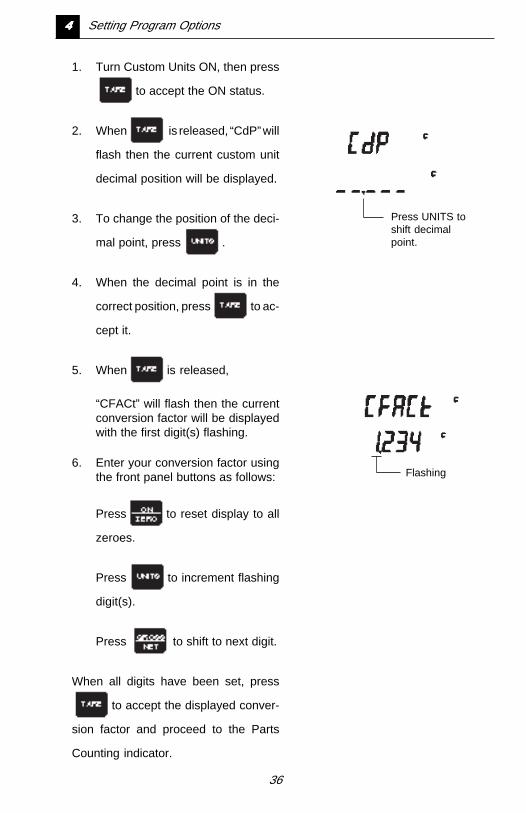
1. Turn Custom Units ON, then press
to accept the ON status.
2. When is released, “CdP” will
flash then the current custom unit
decimal position will be displayed.
3. To change the position of the deci-
mal point, press .
4. When the decimal point is in the
correct position, press to ac-
cept it.
5. When is released,
“CFACt” will flash then the currentconversion factor will be displayedwith the first digit(s) flashing.
6. Enter your conversion factor usingthe front panel buttons as follows:
Press to reset display to all
zeroes.
Press to increment flashing
digit(s).
Press to shift to next digit.
When all digits have been set, press
to accept the displayed conver-
sion factor and proceed to the Parts
Counting indicator.
Press UNITS toshift decimalpoint.
Flashing
44444 Setting Program Options
37
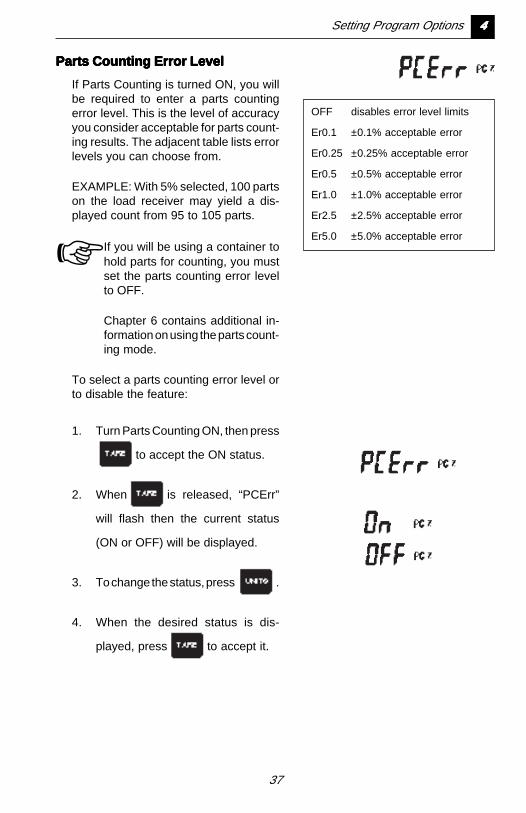
Parts Counting Error LevelParts Counting Error LevelParts Counting Error LevelParts Counting Error LevelParts Counting Error Level
If Parts Counting is turned ON, you willbe required to enter a parts countingerror level. This is the level of accuracyyou consider acceptable for parts count-ing results. The adjacent table lists errorlevels you can choose from.
EXAMPLE: With 5% selected, 100 partson the load receiver may yield a dis-played count from 95 to 105 parts.
☞ If you will be using a container tohold parts for counting, you mustset the parts counting error levelto OFF.
Chapter 6 contains additional in-formation on using the parts count-ing mode.
To select a parts counting error level orto disable the feature:
1. Turn Parts Counting ON, then press
to accept the ON status.
2. When is released, “PCErr”
will flash then the current status
(ON or OFF) will be displayed.
3. To change the status, press .
4. When the desired status is dis-
played, press to accept it.
OFF disables error level limits
Er0.1 ±0.1% acceptable error
Er0.25 ±0.25% acceptable error
Er0.5 ±0.5% acceptable error
Er1.0 ±1.0% acceptable error
Er2.5 ±2.5% acceptable error
Er5.0 ±5.0% acceptable error
Setting Program Options 44444

38
5. If OFF was selected, “SEtUP” will
be displayed when is re-
leased indicating that Unit Selec-
tion is complete.
You can press to return to
the weighing mode, or proceed to
another program option.
If ON was selected, the current partscounting error level will be displayed.
6. To change the error level, repeat-
edly press until the desired
level is displayed.
7. Press to accept the dis-
played error level.
8. When is released, “SEtUP”
will be displayed indicating that Unit
Selection is complete.
You can press to return to
the weighing mode, or proceed to
another program option.
44444 Setting Program Options
39
Auto Shut-Off Timer andAuto Shut-Off Timer andAuto Shut-Off Timer andAuto Shut-Off Timer andAuto Shut-Off Timer andRS232 ParametersRS232 ParametersRS232 ParametersRS232 ParametersRS232 Parameters
The automatic shut-off timer can be en-abled to turn the I 10 off if it is idle for aspecified period of time. Being idle meansno switch depressions, weight changesor RS232 input.
The RS232 parameters enable you toconfigure the RS232 interface for com-munication with other devices such asprinters, computers, etc.
To view or change these parameters:
1. Press and hold to access the
Setup mode.
Release when “SEtUP” is
displayed.
2. Press to access the Auto
Shut-off/RS232 parameters.
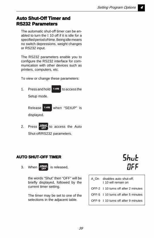
AUTO SHUT-OFF TIMERAUTO SHUT-OFF TIMERAUTO SHUT-OFF TIMERAUTO SHUT-OFF TIMERAUTO SHUT-OFF TIMER
3. When is released,
the words “Shut” then “OFF” will bebriefly displayed, followed by thecurrent timer setting.
The timer may be set to one of theselections in the adjacent table.
A_On disables auto shut-off;I 10 will remain on
OFF-2 I 10 turns off after 2 minutes
OFF-5 I 10 turns off after 5 minutes
OFF-9 I 10 turns off after 9 minutes
Setting Program Options 44444
40
4. To change the setting, repeatedly
press until the desired set-
ting is displayed.
5. Press to accept the dis-
played setting and proceed to the
RS232 parameters.
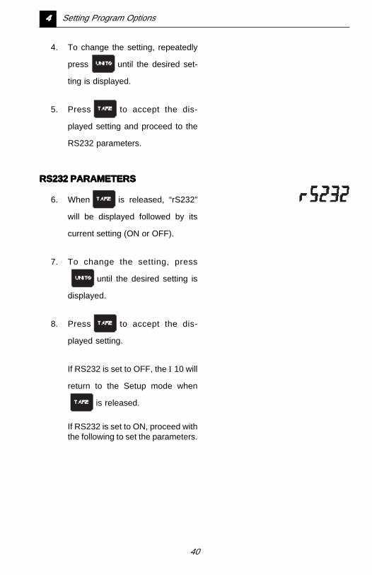
RS232 PARAMETERSRS232 PARAMETERSRS232 PARAMETERSRS232 PARAMETERSRS232 PARAMETERS
6. When is released, “rS232”
will be displayed followed by its
current setting (ON or OFF).
7. To change the setting, press
until the desired setting is
displayed.
8. Press to accept the dis-
played setting.
If RS232 is set to OFF, the I 10 will
return to the Setup mode when
is released.
If RS232 is set to ON, proceed withthe following to set the parameters.
44444 Setting Program Options
41
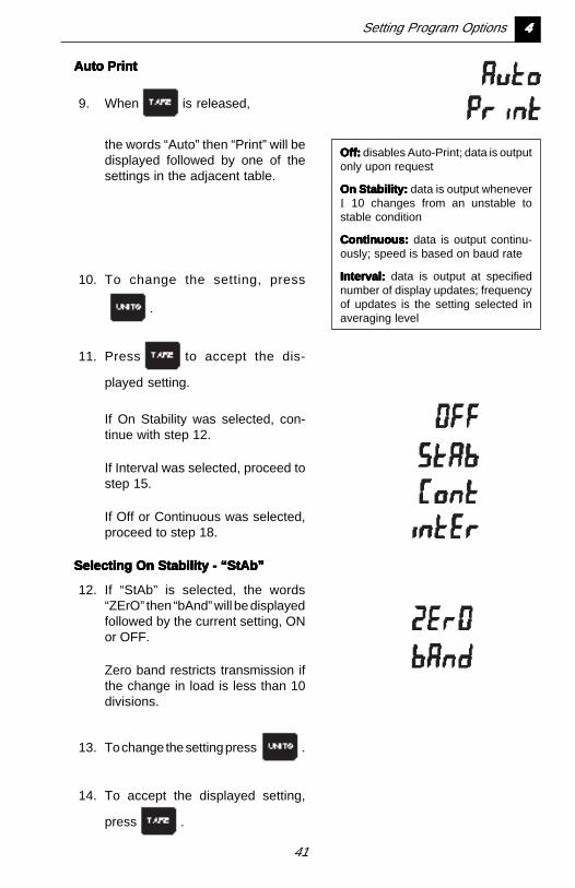
Auto PrintAuto PrintAuto PrintAuto PrintAuto Print
9. When is released,
the words “Auto” then “Print” will bedisplayed followed by one of thesettings in the adjacent table.
Off:Off:Off:Off:Off: disables Auto-Print; data is outputonly upon request
On Stability:On Stability:On Stability:On Stability:On Stability: data is output wheneverI 10 changes from an unstable tostable condition
Continuous:Continuous:Continuous:Continuous:Continuous: data is output continu-ously; speed is based on baud rate
Interval:Interval:Interval:Interval:Interval: data is output at specifiednumber of display updates; frequencyof updates is the setting selected inaveraging level
10. To change the setting, press
.
11. Press to accept the dis-
played setting.
If On Stability was selected, con-tinue with step 12.
If Interval was selected, proceed tostep 15.
If Off or Continuous was selected,proceed to step 18.
Selecting On Stability - “StAb”Selecting On Stability - “StAb”Selecting On Stability - “StAb”Selecting On Stability - “StAb”Selecting On Stability - “StAb”
12. If “StAb” is selected, the words“ZErO” then “bAnd” will be displayedfollowed by the current setting, ONor OFF.
Zero band restricts transmission ifthe change in load is less than 10divisions.
13. To change the setting press .
14. To accept the displayed setting,
press .
Setting Program Options 44444
42
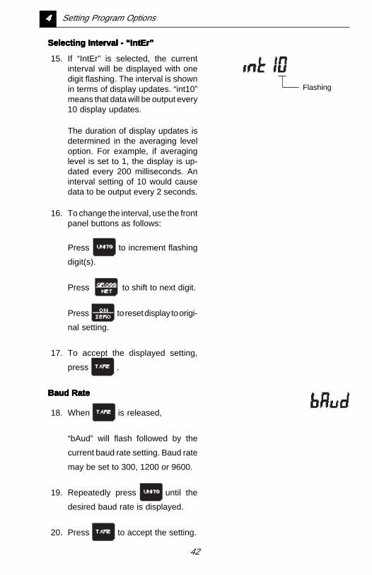
Selecting Interval - “IntEr”Selecting Interval - “IntEr”Selecting Interval - “IntEr”Selecting Interval - “IntEr”Selecting Interval - “IntEr”
15. If “IntEr” is selected, the currentinterval will be displayed with onedigit flashing. The interval is shownin terms of display updates. “int10”means that data will be output every10 display updates.
The duration of display updates isdetermined in the averaging leveloption. For example, if averaginglevel is set to 1, the display is up-dated every 200 milliseconds. Aninterval setting of 10 would causedata to be output every 2 seconds.
16. To change the interval, use the frontpanel buttons as follows:
Press to increment flashing
digit(s).
Press to shift to next digit.
Press to reset display to origi-
nal setting.
17. To accept the displayed setting,
press .
Baud RateBaud RateBaud RateBaud RateBaud Rate
18. When is released,
“bAud” will flash followed by the
current baud rate setting. Baud rate
may be set to 300, 1200 or 9600.
19. Repeatedly press until the
desired baud rate is displayed.
20. Press to accept the setting.
Flashing
44444 Setting Program Options
43
Setting Program Options 44444
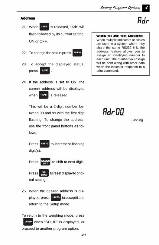
AddressAddressAddressAddressAddress
21. When is released, “Adr” will
flash followed by its current setting,
ON or OFF.
22. To change the status press .
23. To accept the displayed status,
press .
24. If the address is set to ON, the
current address will be displayed
when is released.
This will be a 2-digit number be-
tween 00 and 99 with the first digit
flashing. To change the address,
use the front panel buttons as fol-
lows:
Press to increment flashing
digit(s).
Press to shift to next digit.
Press to reset display to origi-
nal setting.
25. When the desired address is dis-
played, press to accept it and
return to the Setup mode.
To return to the weighing mode, press
when “SEtUP” is displayed, or
proceed to another program option.
WHEN TO USE THE ADDRESSWHEN TO USE THE ADDRESSWHEN TO USE THE ADDRESSWHEN TO USE THE ADDRESSWHEN TO USE THE ADDRESSWhen multiple indicators or scalesare used in a system where theyshare the same RS232 link, theaddress feature allows you toassign an identifying number toeach unit. The number you assignwill be sent along with other datawhen the indicator responds to aprint command.
Flashing
44
Chapter 5:Chapter 5:Chapter 5:Chapter 5:Chapter 5:CalibrationCalibrationCalibrationCalibrationCalibration
The I 10 must be calibrated afterProgram Constants have been ini-tially set, and when any of theProgram Constants are changed(see Chapter 3 - Program Con-stants). Calibration is accessedfrom the Setup mode.
Before beginning calibration youwill need to have the followingitems on hand:
• a calibration weight equal to theCalibration Point entered in theProgram Constants menu (seeChapter 3)
• If linearization will be performed,a weight equal to 1/2 of theCalibration Point will also berequired
• the screwdriver which was pro-vided with the I 10 (not requiredfor factory calibrated benchscales; -C0 models).
☞ Only 2 point calibration isavailable for Legal For Tradeinstallations.
The rear cover of the I 10 must beremoved before calibrating if theSETUP switch is set to OFF. Referto Chapter 1 if needed.
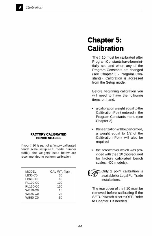
MODEL CAL WT. (lbs)LB30-C0 30LB60-C0 60PL100-C0 100PL150-C0 150WB10-C0 10WB25-C0 25WB50-C0 50
FACTORY CALIBRATEDFACTORY CALIBRATEDFACTORY CALIBRATEDFACTORY CALIBRATEDFACTORY CALIBRATEDBENCH SCALESBENCH SCALESBENCH SCALESBENCH SCALESBENCH SCALES
If your I 10 is part of a factory calibratedbench scale setup (-C0 model numbersuffix), the weights listed below arerecommended to perform calibration.
55555 Calibration
45
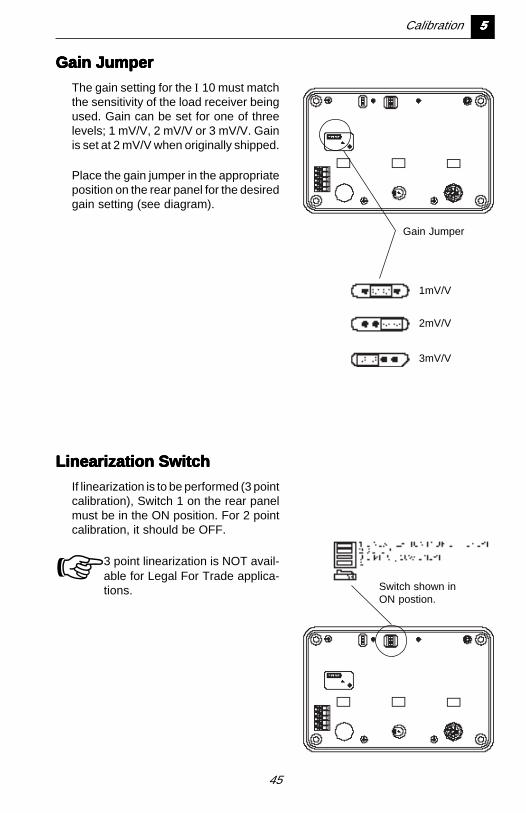
Gain JumperGain JumperGain JumperGain JumperGain Jumper
The gain setting for the I 10 must matchthe sensitivity of the load receiver beingused. Gain can be set for one of threelevels; 1 mV/V, 2 mV/V or 3 mV/V. Gainis set at 2 mV/V when originally shipped.
Place the gain jumper in the appropriateposition on the rear panel for the desiredgain setting (see diagram).
Gain Jumper
Linearization SwitchLinearization SwitchLinearization SwitchLinearization SwitchLinearization Switch
If linearization is to be performed (3 pointcalibration), Switch 1 on the rear panelmust be in the ON position. For 2 pointcalibration, it should be OFF.
☞ 3 point linearization is NOT avail-able for Legal For Trade applica-tions.
1mV/V
2mV/V
3mV/V
Switch shown inON postion.
Calibration 55555
46
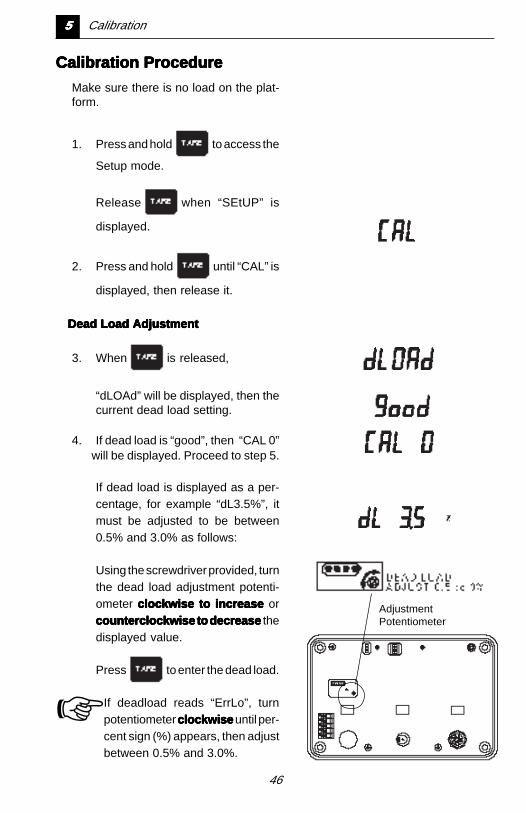
Calibration ProcedureCalibration ProcedureCalibration ProcedureCalibration ProcedureCalibration Procedure
Make sure there is no load on the plat-form.
1. Press and hold to access the
Setup mode.
Release when “SEtUP” is
displayed.
2. Press and hold until “CAL” is
displayed, then release it.
Dead Load AdjustmentDead Load AdjustmentDead Load AdjustmentDead Load AdjustmentDead Load Adjustment
3. When is released,
“dLOAd” will be displayed, then thecurrent dead load setting.
4. If dead load is “good”, then “CAL 0”
AdjustmentPotentiometer
will be displayed. Proceed to step 5.
If dead load is displayed as a per-centage, for example “dL3.5%”, itmust be adjusted to be between0.5% and 3.0% as follows:
Using the screwdriver provided, turnthe dead load adjustment potenti-ometer clockwise to increase clockwise to increase clockwise to increase clockwise to increase clockwise to increase orcounterclockwise to decrease counterclockwise to decrease counterclockwise to decrease counterclockwise to decrease counterclockwise to decrease thedisplayed value.
Press to enter the dead load.
☞ If deadload reads “ErrLo”, turnpotentiometer clockwise clockwise clockwise clockwise clockwise until per-cent sign (%) appears, then adjustbetween 0.5% and 3.0%.
55555 Calibration
47
Calibration 55555
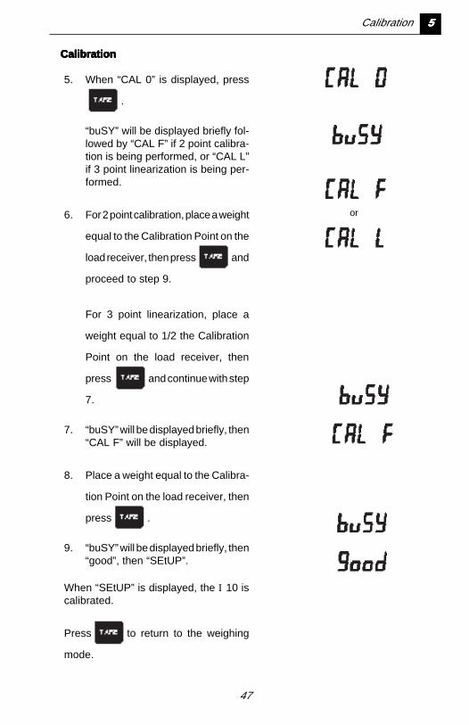
CalibrationCalibrationCalibrationCalibrationCalibration
5. When “CAL 0” is displayed, press
.
“buSY” will be displayed briefly fol-lowed by “CAL F” if 2 point calibra-tion is being performed, or “CAL L”if 3 point linearization is being per-formed.
6. For 2 point calibration, place a weight
equal to the Calibration Point on the
load receiver, then press and
proceed to step 9.
For 3 point linearization, place a
weight equal to 1/2 the Calibration
Point on the load receiver, then
press and continue with step
7.
7. “buSY” will be displayed briefly, then“CAL F” will be displayed.
8. Place a weight equal to the Calibra-
tion Point on the load receiver, then
press .
9. “buSY” will be displayed briefly, then“good”, then “SEtUP”.
When “SEtUP” is displayed, the I 10 iscalibrated.
Press to return to the weighing
mode.
or
48
Chapter 6:Chapter 6:Chapter 6:Chapter 6:Chapter 6:WWWWWeighing,eighing,eighing,eighing,eighing,PPPPParararararts Countingts Countingts Countingts Countingts Countingand Printingand Printingand Printingand Printingand Printing
The weighing units and modesavailable to you depend on whichones were enabled using the UnitSelection feature (see Chapter 4).
66666 Weighing, Parts Counting and Printing
49
Unit/ModeIndicators
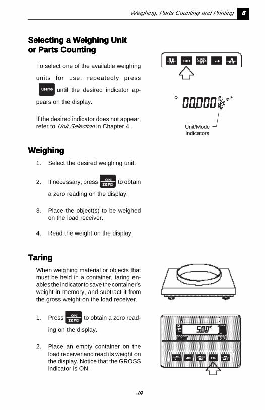
Selecting a Weighing UnitSelecting a Weighing UnitSelecting a Weighing UnitSelecting a Weighing UnitSelecting a Weighing Unitor Parts Countingor Parts Countingor Parts Countingor Parts Countingor Parts Counting
To select one of the available weighing
units for use, repeatedly press
until the desired indicator ap-
pears on the display.
If the desired indicator does not appear,refer to Unit Selection in Chapter 4.
WeighingWeighingWeighingWeighingWeighing
1. Select the desired weighing unit.
2. If necessary, press to obtain
a zero reading on the display.
3. Place the object(s) to be weighedon the load receiver.
4. Read the weight on the display.
TaringTaringTaringTaringTaring
When weighing material or objects thatmust be held in a container, taring en-ables the indicator to save the container’sweight in memory, and subtract it fromthe gross weight on the load receiver.
1. Press to obtain a zero read-
ing on the display.
2. Place an empty container on theload receiver and read its weight onthe display. Notice that the GROSSindicator is ON.
Weighing, Parts Counting and Printing 66666
50
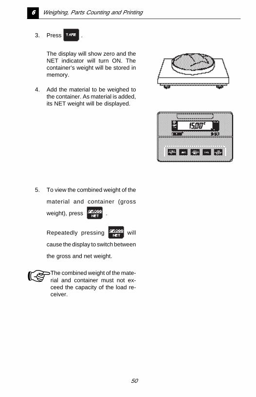
3. Press .
The display will show zero and theNET indicator will turn ON. Thecontainer’s weight will be stored inmemory.
4. Add the material to be weighed tothe container. As material is added,its NET weight will be displayed.
5. To view the combined weight of the
material and container (gross
weight), press .
Repeatedly pressing will
cause the display to switch between
the gross and net weight.
☞ The combined weight of the mate-rial and container must not ex-ceed the capacity of the load re-ceiver.
66666 Weighing, Parts Counting and Printing
51
Parts CountingParts CountingParts CountingParts CountingParts Counting
Parts Counting mode must first be en-abled in the Unit Selection menu beforeit can be used. See Unit Selection inChapter 4.
In this mode, the I 10 calculates anddisplays the quantity of parts you placeon the load receiver. Since the indicatordetermines the quantity based on theaverage piece weight of a single part, allparts must be reasonably uniform inweight.
To perform parts counting, use the fol-lowing procedure:
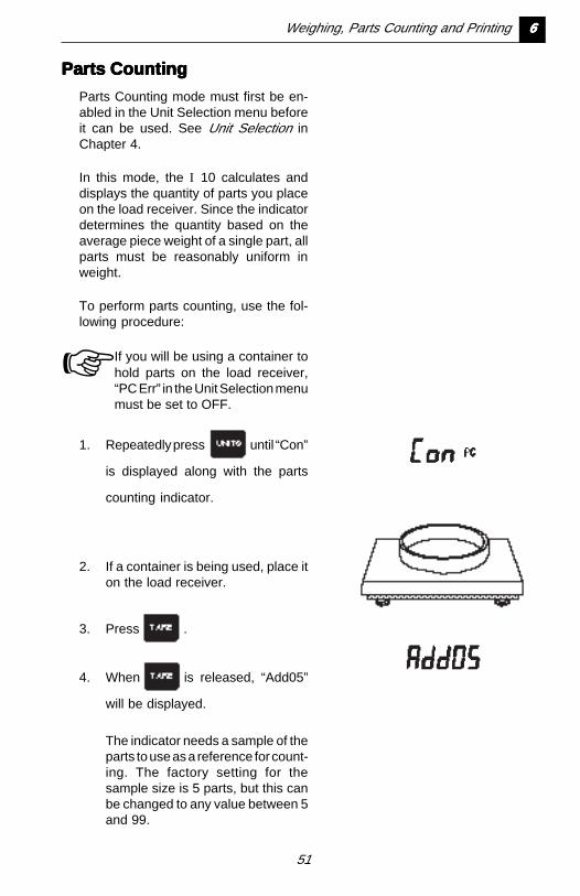
☞ If you will be using a container tohold parts on the load receiver,“PC Err” in the Unit Selection menumust be set to OFF.
1. Repeatedly press until “Con”
is displayed along with the parts
counting indicator.
2. If a container is being used, place iton the load receiver.
3. Press .
4. When is released, “Add05”
will be displayed.
The indicator needs a sample of theparts to use as a reference for count-ing. The factory setting for thesample size is 5 parts, but this canbe changed to any value between 5and 99.
Weighing, Parts Counting and Printing 66666
52
66666 Weighing, Parts Counting and Printing
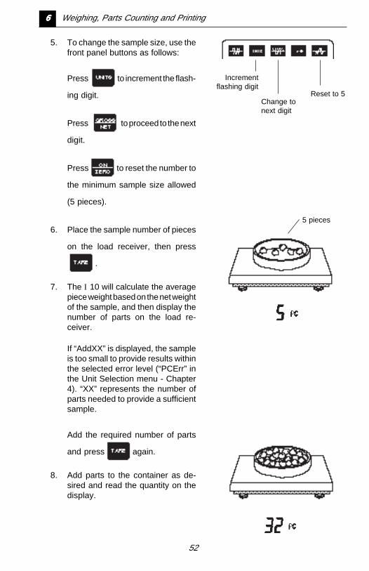
5. To change the sample size, use thefront panel buttons as follows:
Press to increment the flash-
ing digit.
Press to proceed to the next
digit.
Press to reset the number to
the minimum sample size allowed
(5 pieces).
6. Place the sample number of pieces
on the load receiver, then press
.
7. The I 10 will calculate the averagepiece weight based on the net weightof the sample, and then display thenumber of parts on the load re-ceiver.
If “AddXX” is displayed, the sampleis too small to provide results withinthe selected error level (“PCErr” inthe Unit Selection menu - Chapter4). “XX” represents the number ofparts needed to provide a sufficientsample.
Add the required number of parts
and press again.
8. Add parts to the container as de-sired and read the quantity on thedisplay.
Incrementflashing digit
Change tonext digit
Reset to 5
5 pieces
53
Weighing, Parts Counting and Printing 66666
9. To display the net weight of the
parts on the load receiver, press
.
Pressing a second time will
display the GROSS weight (con-
tainer and parts).
Pressing a third time will
display the quantity again.
10. To exit or restart parts counting,
press and hold until “Con” is
displayed.
Press to exit parts counting
and change to another weighing
mode, or return to step 2 to restart
parts counting.
PrintingPrintingPrintingPrintingPrinting
The RS232 interface may be used with aprinter, computer or other output device.To output display data at any time,
press .
The output format is illustrated under the“P” command in the RS232 COMMANDTABLE in Chapter 7. For more informa-tion on printing and using the RS232interface, refer to Auto Shut-off/RS232Menu in Chapter 4, and RS232 Interface- Chapter 7.
54
Chapter 7:Chapter 7:Chapter 7:Chapter 7:Chapter 7:RS232 InterfaceRS232 InterfaceRS232 InterfaceRS232 InterfaceRS232 Interface
I 10 Indicators are equipped witha bi-directional RS232 compatibleinterface for communication withprinters and computers.
When the I 10 is connected di-rectly to a printer, displayed datacan be output at any time by sim-ply pressing the PRINT button, orby using the Auto Print feature.
Connecting the I 10 to a computerenables operation from the com-puter, as well as receiving datasuch as displayed weight, weigh-ing mode, stability status, etc.
This chapter describes the hard-ware and software provided withthe I 10.
77777 RS232 Interface
55
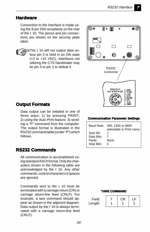
HardwareHardwareHardwareHardwareHardware
Connection to the interface is made us-ing the 8-pin DIN receptacle on the rearof the I 10. The pinout and pin connec-tions are shown on the security platelabel.
☞ The I 10 will not output data un-less pin 3 is held in an ON state(+3 to +15 VDC). Interfaces notutilizing the CTS handshake maytie pin 3 to pin 1 to defeat it. RS232
Connector
Output FormatsOutput FormatsOutput FormatsOutput FormatsOutput Formats
Data output can be initiated in one ofthree ways: 1) by pressing PRINT;2) using the Auto Print feature; 3) send-ing a “P” command from the computer.The output format is illustrated in theRS232 command table (under “P”) whichfollows.
RS232 CommandsRS232 CommandsRS232 CommandsRS232 CommandsRS232 Commands
All communication is accomplished us-ing standard ASCII format. Only the char-acters shown in the following table areacknowledged by the I 10. Any othercommands, control characters or spacesare ignored.
Commands sent to the I 10 must beterminated with a carriage return (CR) orcarriage return-line feed (CRLF). Forexample, a tare command should ap-pear as shown in the adjacent diagram.Data output by the I 10 is always termi-nated with a carriage return-line feed(CRLF).
TARE COMMANDTARE COMMANDTARE COMMANDTARE COMMANDTARE COMMAND
Field: T CR LFLength: 1 1 1
Communication Parameter SettingsCommunication Parameter SettingsCommunication Parameter SettingsCommunication Parameter SettingsCommunication Parameter Settings
Baud Rate: 300, 1200 or 9600selectable in Print menu
Start Bit: 1Data Bits: 7Parity: NoneStop Bits: 2
RS232 Interface 77777
56
77777 RS232 Interface
RS232 COMMAND TABLERS232 COMMAND TABLERS232 COMMAND TABLERS232 COMMAND TABLERS232 COMMAND TABLE
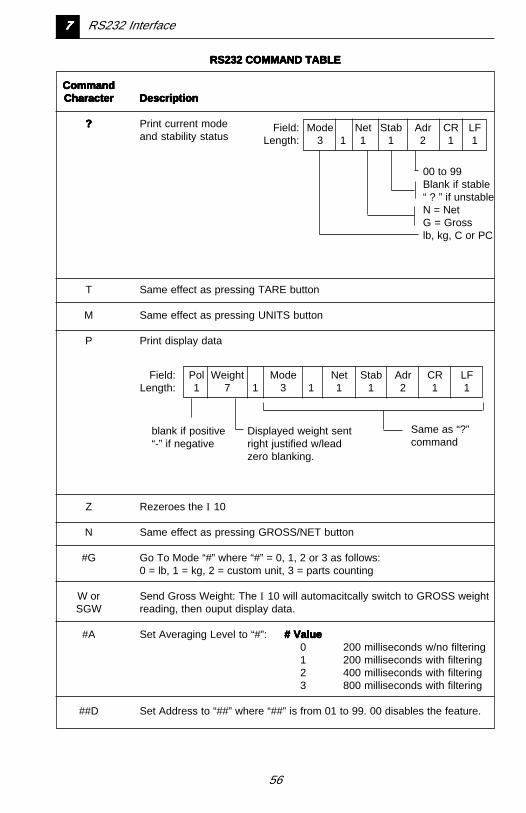
CommandCommandCommandCommandCommandCharacterCharacterCharacterCharacterCharacter DescriptionDescriptionDescriptionDescriptionDescription
????? Print current modeand stability status
T Same effect as pressing TARE button
M Same effect as pressing UNITS button
P Print display data
Z Rezeroes the I 10
N Same effect as pressing GROSS/NET button
#G Go To Mode “#” where “#” = 0, 1, 2 or 3 as follows:0 = lb, 1 = kg, 2 = custom unit, 3 = parts counting
W or Send Gross Weight: The I 10 will automacitcally switch to GROSS weightSGW reading, then ouput display data.
#A Set Averaging Level to “#”: # Value# Value# Value# Value# Value0 200 milliseconds w/no filtering1 200 milliseconds with filtering2 400 milliseconds with filtering3 800 milliseconds with filtering
##D Set Address to “##” where “##” is from 01 to 99. 00 disables the feature.
00 to 99Blank if stable“ ? ” if unstableN = NetG = Grosslb, kg, C or PC
Field: Mode Net Stab Adr CR LFLength: 3 1 1 1 2 1 1
Field: Pol Weight Mode Net Stab Adr CR LFLength: 1 7 1 3 1 1 1 2 1 1
blank if positive“-” if negative
Same as “?”command
Displayed weight sentright justified w/leadzero blanking.
57
RS232 Interface 77777
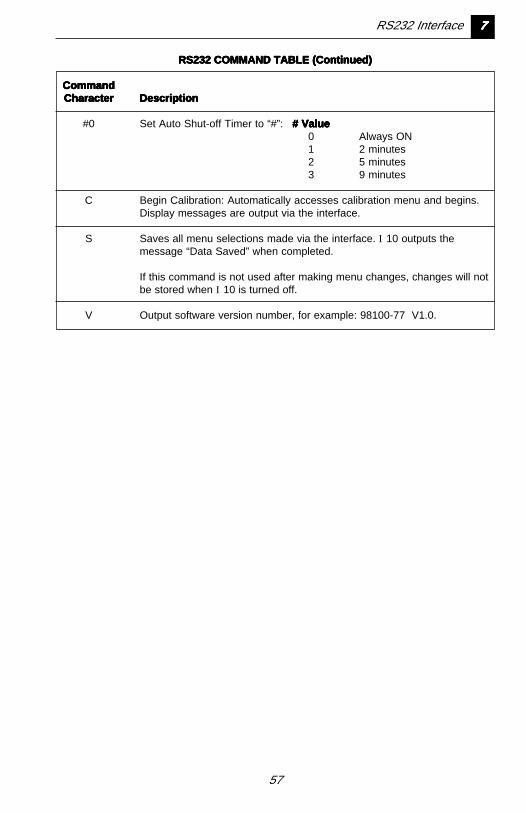
RS232 COMMAND TABLE (Continued)RS232 COMMAND TABLE (Continued)RS232 COMMAND TABLE (Continued)RS232 COMMAND TABLE (Continued)RS232 COMMAND TABLE (Continued)
CommandCommandCommandCommandCommandCharacterCharacterCharacterCharacterCharacter DescriptionDescriptionDescriptionDescriptionDescription
#0 Set Auto Shut-off Timer to “#”: # Value# Value# Value# Value# Value0 Always ON1 2 minutes2 5 minutes3 9 minutes
C Begin Calibration: Automatically accesses calibration menu and begins.Display messages are output via the interface.
S Saves all menu selections made via the interface. I 10 outputs themessage “Data Saved” when completed.
If this command is not used after making menu changes, changes will notbe stored when I 10 is turned off.
V Output software version number, for example: 98100-77 V1.0.

58
Chapter 8:Chapter 8:Chapter 8:Chapter 8:Chapter 8:Legal For Legal For Legal For Legal For Legal For TTTTTraderaderaderaderadeSealingSealingSealingSealingSealing
When the I 10 is installed in aLegal For Trade application, it mustbe sealed as explained in thischapter to prevent unauthorizedchanges to setup and calibrationdata.
88888 Legal For Trade Sealing
59
Setup and CalibrationSetup and CalibrationSetup and CalibrationSetup and CalibrationSetup and CalibrationRestrictionsRestrictionsRestrictionsRestrictionsRestrictions
When LFT is selected in the programconstants menu, the following param-eter settings are automatically restrictedby the software:
• Auto-Zero Tracking may be set at 0.6,1 or 3.
• Only pounds and/or kilograms may beused.
• RS232 Auto Print may be set to “At”(OFF) or “StAb” (output on stability)only.
• Display resolution may be set to amaximum of 10,000 divisions.
• Calibration is restricted to 2 Point Cali-bration.
Verify that the I 10 has been configuredaccording to these restrictions.
☞ The I 10 capacity and readabilitymust match that of the NTEP cer-tified Class III or IIIL or CanadianLegal Metrology Branch GeneralClass load receiver it will be usedwith.
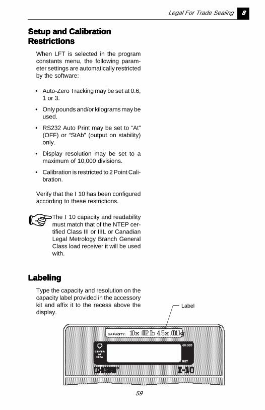
LabelingLabelingLabelingLabelingLabeling
Type the capacity and resolution on thecapacity label provided in the accessorykit and affix it to the recess above thedisplay.
Label
Legal For Trade Sealing 88888
60
88888 Legal For Trade Sealing
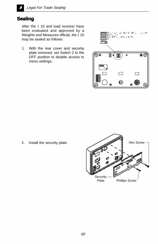
SealingSealingSealingSealingSealing
After the I 10 and load receiver havebeen evaluated and approved by aWeights and Measures official, the I 10may be sealed as follows:
1. With the rear cover and securityplate removed, set Switch 2 to theOFF position to disable access tomenu settings.
Hex Screw
SecurityPlate Phillips Screw
2. Install the security plate.
61
Legal For Trade Sealing 88888
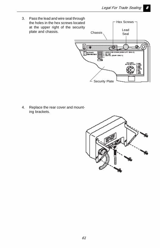
3. Pass the lead and wire seal throughthe holes in the hex screws locatedat the upper right of the securityplate and chassis.
4. Replace the rear cover and mount-ing brackets.
LeadSeal
Hex Screws
Security Plate
Chassis
62
Chapter 9:Chapter 9:Chapter 9:Chapter 9:Chapter 9:TTTTTrrrrroubouboubouboub leshootingleshootingleshootingleshootingleshooting
The information in this chapter isintended to help identify and cor-rect errors that may be made ininstalling or operating the I 10. Itincludes:
• a troubleshooting chart
• a description of messages thatmay appear on the display
• information on proper care andmaintenance
99999 Troubleshooting
63
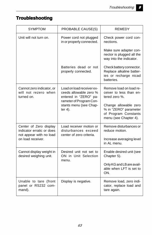
TroubleshootingTroubleshootingTroubleshootingTroubleshootingTroubleshooting
PROBABLE CAUSE(S)
Power cord not pluggedin or properly connected.
Batteries dead or notproperly connected.
Load on load receiver ex-ceeds allowable zero %entered in “ZERO” pa-rameter of Program Con-stants menu (see Chap-ter 4).
Load receiver motion ordisturbances exceedcenter of zero criteria.
Desired unit not set toON in Unit Selectionmenu.
Display is negative.
REMEDY
Check power cord con-nections.
Make sure adapter con-nector is plugged all theway into the indicator.
Check battery connector.Replace alkaline batter-ies or recharge nicadbatteries.
Remove load on load re-ceiver to less than en-tered zero %.
Change allowable zero% in “ZERO” parameterof Program Constantsmenu (see Chapter 4).
Remove disturbances orreduce motion.
Increase averaging levelin AL menu.
Enable desired unit (seeChapter 5).
Only KG and LB are avail-able when LFT is set toON.
Remove load, zero indi-cator, replace load andtare again.
SYMPTOM
Unit will not turn on.
Cannot zero indicator, orwill not rezero whenturned on.
Center of Zero displayindicator erratic or doesnot appear with no loadon load receiver.
Cannot display weight indesired weighing unit.
Unable to tare (frontpanel or RS232 com-mand).
Troubleshooting 99999
64
PROBABLE CAUSE(S)
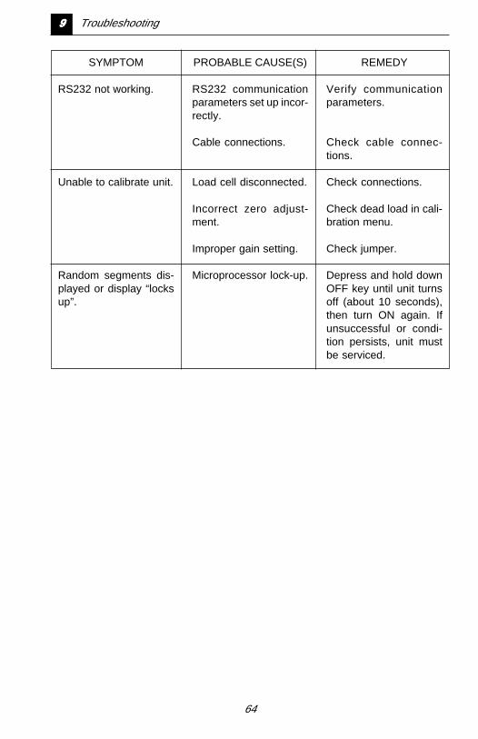
RS232 communicationparameters set up incor-rectly.
Cable connections.
Load cell disconnected.
Incorrect zero adjust-ment.
Improper gain setting.
Microprocessor lock-up.
REMEDY
Verify communicationparameters.
Check cable connec-tions.
Check connections.
Check dead load in cali-bration menu.
Check jumper.
Depress and hold downOFF key until unit turnsoff (about 10 seconds),then turn ON again. Ifunsuccessful or condi-tion persists, unit mustbe serviced.
SYMPTOM
RS232 not working.
Unable to calibrate unit.
Random segments dis-played or display “locksup”.
99999 Troubleshooting
65
Troubleshooting 99999
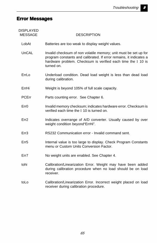
Error MessagesError MessagesError MessagesError MessagesError Messages
DISPLAYEDMESSAGE DESCRIPTION
LobAt Batteries are too weak to display weight values.
UnCAL Invalid checksum of non volatile memory; unit must be set up forprogram constants and calibrated. If error remains, it indicates ahardware problem. Checksum is verified each time the I 10 isturned on.
ErrLo Underload condition. Dead load weight is less than dead loadduring calibration.
ErrHi Weight is beyond 105% of full scale capacity.
PCErr Parts counting error. See Chapter 6.
Err0 Invalid memory checksum; indicates hardware error. Checksum isverified each time the I 10 is turned on.
Err2 Indicates overrange of A/D converter. Usually caused by overweight condition beyond“ErrHi”.
Err3 RS232 Communication error - Invalid command sent.
Err5 Internal value is too large to display. Check Program Constantsmenu or Custom Units Conversion Factor.
Err7 No weight units are enabled. See Chapter 4.
tohi Calibration/Linearization Error. Weight may have been addedduring calibration procedure when no load should be on loadreceiver.
toLo Calibration/Linearization Error. Incorrect weight placed on loadreceiver during calibration procedure.
66
99999 Troubleshooting
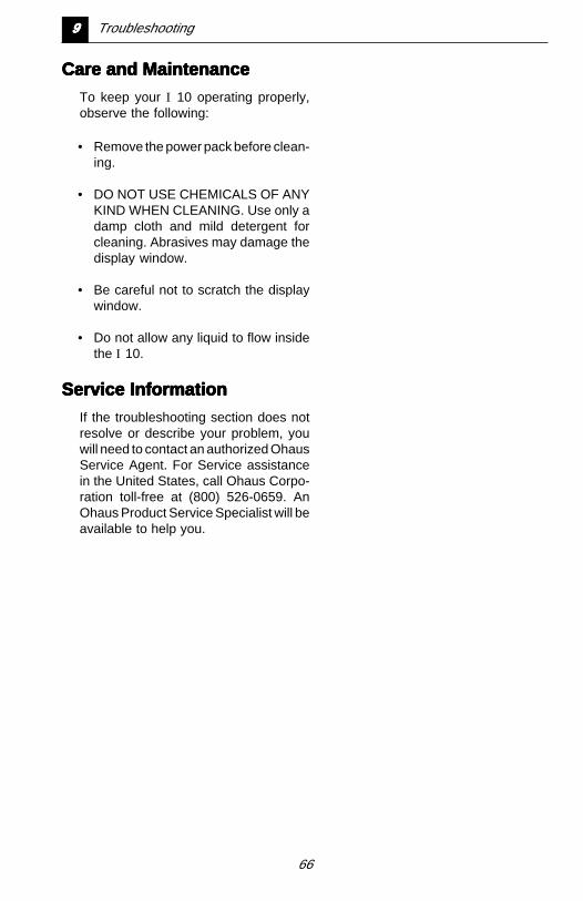
Care and MaintenanceCare and MaintenanceCare and MaintenanceCare and MaintenanceCare and Maintenance
To keep your I 10 operating properly,observe the following:
• Remove the power pack before clean-ing.
• DO NOT USE CHEMICALS OF ANYKIND WHEN CLEANING. Use only adamp cloth and mild detergent forcleaning. Abrasives may damage thedisplay window.
• Be careful not to scratch the displaywindow.
• Do not allow any liquid to flow insidethe I 10.
Service InformationService InformationService InformationService InformationService Information
If the troubleshooting section does notresolve or describe your problem, youwill need to contact an authorized OhausService Agent. For Service assistancein the United States, call Ohaus Corpo-ration toll-free at (800) 526-0659. AnOhaus Product Service Specialist will beavailable to help you.

67
Chapter 10:Chapter 10:Chapter 10:Chapter 10:Chapter 10:Specifications,Specifications,Specifications,Specifications,Specifications,ReplacementReplacementReplacementReplacementReplacementPPPPParararararts andts andts andts andts andAccessoriesAccessoriesAccessoriesAccessoriesAccessories
Specifications, Replacement Parts and Accessories 1010101010
68
1010101010 Specifications, Replacement Parts and Accessories
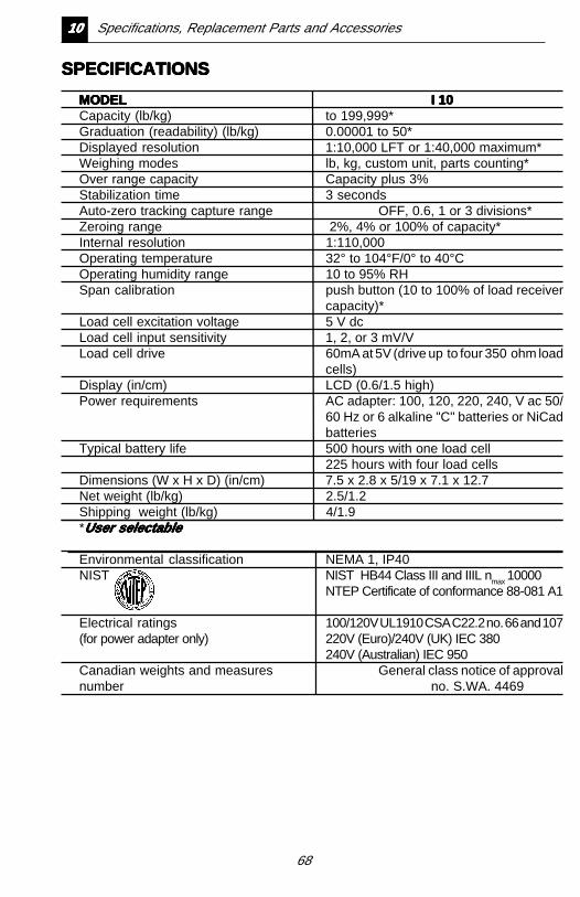
SPECIFICATIONSSPECIFICATIONSSPECIFICATIONSSPECIFICATIONSSPECIFICATIONS
MODELMODELMODELMODELMODEL I 10I 10I 10I 10I 10Capacity (lb/kg) to 199,999*Graduation (readability) (lb/kg) 0.00001 to 50*Displayed resolution 1:10,000 LFT or 1:40,000 maximum*Weighing modes lb, kg, custom unit, parts counting*Over range capacity Capacity plus 3%Stabilization time 3 secondsAuto-zero tracking capture range OFF, 0.6, 1 or 3 divisions*Zeroing range 2%, 4% or 100% of capacity*Internal resolution 1:110,000Operating temperature 32° to 104°F/0° to 40°COperating humidity range 10 to 95% RHSpan calibration push button (10 to 100% of load receiver
capacity)*Load cell excitation voltage 5 V dcLoad cell input sensitivity 1, 2, or 3 mV/VLoad cell drive 60mA at 5V (drive up to four 350 ohm load
cells)Display (in/cm) LCD (0.6/1.5 high)Power requirements AC adapter: 100, 120, 220, 240, V ac 50/
60 Hz or 6 alkaline "C" batteries or NiCadbatteries
Typical battery life 500 hours with one load cell225 hours with four load cells
Dimensions (W x H x D) (in/cm) 7.5 x 2.8 x 5/19 x 7.1 x 12.7Net weight (lb/kg) 2.5/1.2Shipping weight (lb/kg) 4/1.9*User selectableUser selectableUser selectableUser selectableUser selectable
Environmental classification NEMA 1, IP40NIST NIST HB44 Class III and IIIL nmax 10000
NTEP Certificate of conformance 88-081 A1
Electrical ratings 100/120V UL1910 CSA C22.2 no. 66 and 107(for power adapter only) 220V (Euro)/240V (UK) IEC 380
240V (Australian) IEC 950Canadian weights and measures General class notice of approvalnumber no. S.WA. 4469
69
Specifications, Replacement Parts and Accessories 1010101010
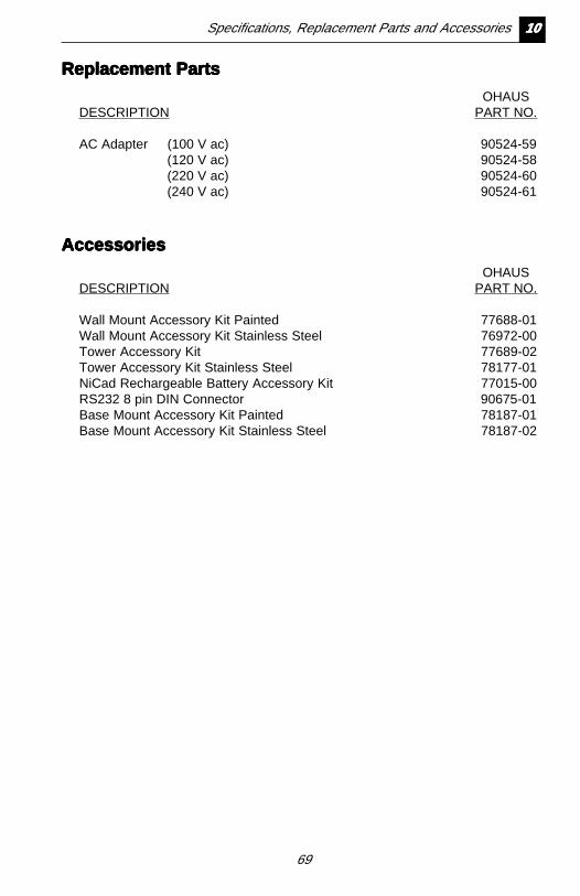
Replacement PartsReplacement PartsReplacement PartsReplacement PartsReplacement Parts
OHAUSDESCRIPTION PART NO.
AC Adapter (100 V ac) 90524-59(120 V ac) 90524-58(220 V ac) 90524-60(240 V ac) 90524-61
AccessoriesAccessoriesAccessoriesAccessoriesAccessories
OHAUSDESCRIPTION PART NO.
Wall Mount Accessory Kit Painted 77688-01Wall Mount Accessory Kit Stainless Steel 76972-00Tower Accessory Kit 77689-02Tower Accessory Kit Stainless Steel 78177-01NiCad Rechargeable Battery Accessory Kit 77015-00RS232 8 pin DIN Connector 90675-01Base Mount Accessory Kit Painted 78187-01Base Mount Accessory Kit Stainless Steel 78187-02
70
A1A1A1A1A1 Common Custom Unit Conversions
Appendix 1:Appendix 1:Appendix 1:Appendix 1:Appendix 1:CommonCommonCommonCommonCommonCustom UnitCustom UnitCustom UnitCustom UnitCustom UnitConConConConConververververversionssionssionssionssions
The table on the following pagelists several commonly used con-version factors for the custom unitfeature.
71
Common Custom Unit Conversions A1A1A1A1A1
Conversion FactorsConversion FactorsConversion FactorsConversion FactorsConversion Factors
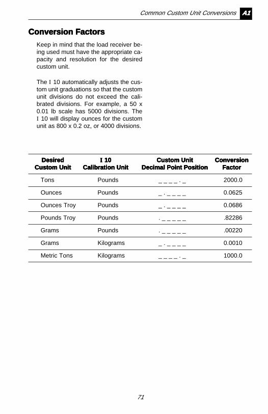
Keep in mind that the load receiver be-ing used must have the appropriate ca-pacity and resolution for the desiredcustom unit.
The I 10 automatically adjusts the cus-tom unit graduations so that the customunit divisions do not exceed the cali-brated divisions. For example, a 50 x0.01 lb scale has 5000 divisions. TheI 10 will display ounces for the customunit as 800 x 0.2 oz, or 4000 divisions.
DesiredDesiredDesiredDesiredDesired IIIII 10 10 10 10 10 Custom UnitCustom UnitCustom UnitCustom UnitCustom Unit ConversionConversionConversionConversionConversionCustom UnitCustom UnitCustom UnitCustom UnitCustom Unit Calibration UnitCalibration UnitCalibration UnitCalibration UnitCalibration Unit Decimal Point PositionDecimal Point PositionDecimal Point PositionDecimal Point PositionDecimal Point Position FactorFactorFactorFactorFactor
Tons Pounds _ _ _ _ . _ 2000.0
Ounces Pounds _ . _ _ _ _ 0.0625
Ounces Troy Pounds _ . _ _ _ _ 0.0686
Pounds Troy Pounds . _ _ _ _ _ .82286
Grams Pounds . _ _ _ _ _ .00220
Grams Kilograms _ . _ _ _ _ 0.0010
Metric Tons Kilograms _ _ _ _ . _ 1000.0

72
Limited WarrantyLimited WarrantyLimited WarrantyLimited WarrantyLimited Warranty
Ohaus products are warranted against defects in materials andworkmanship from the date of delivery through the duration of thewarranty period. During the warranty period Ohaus will repair, or,at its option, replace any component(s) that proves to be defectiveat no charge, provided that the product is returned, freight prepaid,to Ohaus.
This warranty does not apply if the product has been damaged byaccident or misuse, exposed to radioactive or corrosive materials,has foreign material penetrating to the inside of the product, or asa result of service or modification by other than Ohaus. In lieu of aproperly returned warranty registration card, the warranty periodshall begin on the date of shipment to the authorized dealer. Noother express or implied warranty is given by Ohaus Corporation.Ohaus Corporation shall not be liable for any consequentialdamages.
As warranty legislation differs from state to state and country tocountry, please contact Ohaus or your local Ohaus dealer forfurther details.

73
Ohaus Corporation29 Hanover Road,Florham Park, NJ 07932, USATel: (973) 377-9000,Fax: (973) 593-0359
With offices worldwide.
P/N 76959-04 © Ohaus Corporation 1993, 1999, all rights reserved.