of vacuum insulation - apps.dtic.mil · high power vacuum tubes used in many high power radar...
TRANSCRIPT
°.
STECHNICAL REPORT ECOM-O0394-'
," IHIGH VOLTAGE BREAKDOWNS
• HSTUDY*HANDBOOK OF VACUUM INSULATION
I Prepared by:
M. J. Mulcahy and P C. Bolin
ION PHYSICS CORPORATION
BURLINGTON. MASSACHUSETTS DF)7 C
MARCH 1971g
DISTRIBUTION STATEMENT
* This document has been approved for public
* release and sale; its distribution is unlimited0
ECOMUNITED STATES ARMY ELECTRONICS COMMAND FORT MONMOUTH, N.J. 07703
-'ONSORED BY: Advanced Research Projects Agency, ARPA Order No. 517.ONTRACT DA- 28-043-AMC-00394(E)
ION PHYSICS CORPORATIONBurlington, Massachusetts 01803
ge.,•,odced by ••
NATIONAL TECHNICALINFORMATION SERVICE S77
AumE for
GATI W11ITE sEIVrON
.... .. . . . ..m . .. . . . ..
ooK •LJ s:Crion f[].'NAt. C23.3,
. , ,' , ,• ...t ....... .... ... ... ..
Ish2'I AVARML~L7f ONDESSOI£T. o , rL • •a SEGIAL
LM .
NOTICES
Disclaimers
The findings in this report are not to beconstrued as an official Department totheArmy position, unless so designatedby the authorized documents.
The citation of trade names and namesof manufacturers in this report is not tobe construed as official Government in-dorsement or approval of commercialproducts or services referenced herein.
Disposition
Destroy this report when it is no longerneeded. Do not return to the originator.
4
4,i,I

BestAvailable
Copy
Unclassifiedsecuntq Classafac,ation _____, __, ______
DOCUMENT CONTROL DATA- R & Drcur,tt , lessItieton of ttie., body ou ab.trorr and indeuing annotatlon must bo toted when the OVerall reft is C1888ified)
'NIGINA rI NG A CTIVTIY TV(Corportte &uthor) Ifa. REPORT SIECURITY CLASSIFICATION
Ion Physics Corporation UnclassifiedSouth Bedford Street 2b. GROUP
Burlington, Massachusetts 01803REPORT TITLE
Handbook of Vacuum Insulation
4 DESCR IPT IVE Noy Es (?ýyp* of report and Inclusive dalca)
Part of High Voltage Breakdown Study Program"I Au TNO4 IS (First naine, middle tnitial, last niame)
Mulcahy, Michael J.; Bolin, Philip C.
SEPORT DATE 7". TOTAL NO. OF PAGES 7b. NO. OF RIEFS
February 1971 82 46Ila CONTRACT OR GRANT NO. am. ORIGINATOWS REPORT NUMV611ERISI
DA-28-043-AMC-00394(E)b, PROJECT NO
0. 1 91b. OYHER REPORT NOiS1 (Any other n&mberI that may be aseignedthie report)
d. ECOM-00394-;Z10II0 OISTRIMUTION STATEMENT
This document has been approved for public release and sale; its distribution isunlimited.
It ¶UPPLEUENTARy NOTES 1I2. SPONSORING MILITARY ACTIVITY
Advanced Research Projects Agency I U.S. Army Electronics CommandARPA Order No. 517 j Fort Monmouth, New Jersey 07703
__ Attn •AMSFT.-Tc[-TS13A S TRAL 
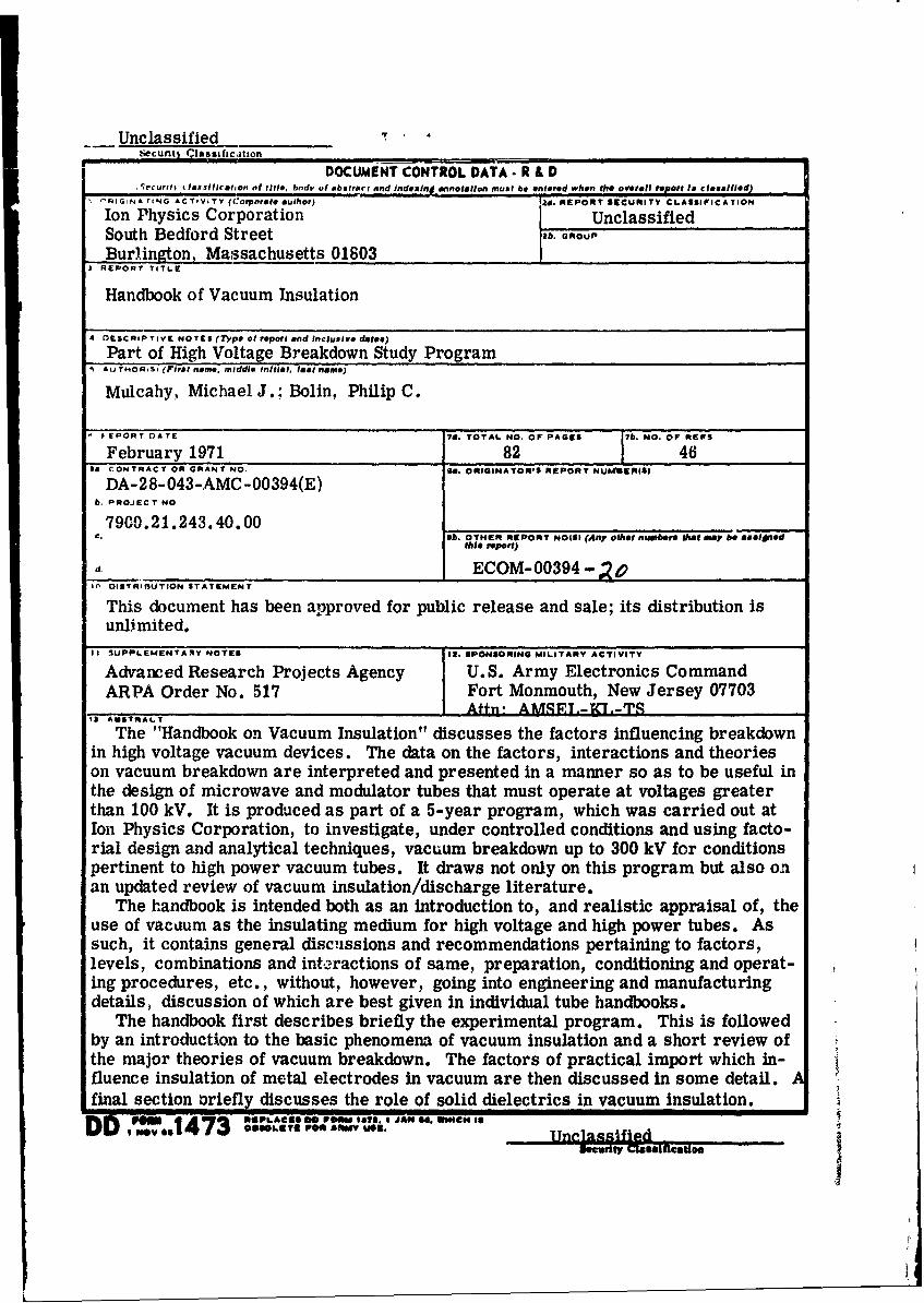
The "Handbook on Vacuum Insulation" discusses the factors influencing breakdownin high voltage vacuum devices. The data on the factors, interactions and theorieson vacuum breakdown are interpreted and presented in a manner so as to be useful inthe design of microwave and modulator tubes that must operate at voltages greaterthan 100 kV. It is produced as part of a 5-year program, which was carried out atIon Physics Corporation, to investigate, under controlled conditions and using facto-rial design and analytical techniques, vacuum breakdown up to 300 kV for conditionspertinent to high power vacuum tubes. It draws not only on this program but also onan updated review of vacuum insulation/discharge literature.
The handbook is intended both as an introduction to, and realistic appraisal of, theuse of vacuum as the insulating medium for high voltage and high power tubes. Assuch, it contains general disc-issions and recommendations pertaining to factors,levels, combinations and interactions of same, preparation, conditioning and operat-ing procedures, etc., without, however, going into engineering and manufacturingdetails, discussion of which are best given in individual tube handbooks.
The handbook first describes briefly the experimental program. This is followedby an introduction to the basic phenomena of vacuum insulation and a short review ofthe major theories of vacuum breakdown. The factors of practical import which in-fluence insulation of metal electrodes in vacuum are then discussed in some detail.final section oriefly discusses the role of solid dielectrics in vacuum insulation.
D D or A'emIIS*S3 ..p.. e POm '1"11 JAO# 04 lHI Ict .
UnclassifiedSecurity LCllullflcation
LINK A LINK 0 LfNK CKEY WONlOS - -ROLE wI' POLK WT POLK WY
Electrical Breakdown in VacuumFactors Influencing Vacuum BreakdownPrebreakdown Phenomena in VacuumCriteria for Vacuum BreakdownOptical and X-RadiationPartial Pressure and Gap CurrentFactorial and Statistical DesignMicrodischargesElectric Field Enhancement and EtchingElectron Beam HeatingConditioning ProceduresEnergy Conditioning and DiversionMagmetic Field and Series ResistanceBarium ContaminationElectf de Materials and Surface PropertiesElectrode Firing and Gas ContentBreakdown Voltage and Voltage CollapseTime Effects and Pulse BreakdownElectrode Gap and Area EffectsPressure and Temperature Effects;Dielectric CoatingsInsulator Flashover and GradingField Emission Theory of Vacuum BreakdownParticle Exchange Theory of Vacuum BreakdownClump Theory of Vacuum Breakdown
!I
Unclassified
II
Technical Report ECOM 0 39O -. Ao AD-
March 1971
HANDBOOK OF VACUUM INSULATION
Contract No. DA-28-043-AMC-00394(E)AMC Task No. 7900. 21. 243. 40.00
Prepared for:
U.S. ARMY ELECTRONICS COMMANDFORT MONMOUTH, NEW JERSEY
Sponsored by:
ADVANCED RESEARCH PROJECTS AGENCYARPA Order No. 517
Prepared by:
M. J. Mulcahy and P. C. Bolin
ION PHYSICS CORPORATIONBURLINGTON, MASSACHUSETTS
DISTRIBUTION STATEMENT
This document has been approved for publicrelease and sale; its distribution is unlimited.
1.N
PUR POSE
The factors influencing breakdown in high voltage vacuum
devices will be discussed. Data and concepts will be presented which
should be useful in the design of microwave and modulator tubes that
must operate at voltages greater than 100 kV.
it2
TABLE OF CONTENTS
Section Page
PURPOSE
I INTRODUCTION 1-I
2 HIGH VOLTAGE VACUUM BREAKDOWN PROGRAM 2-1
2.1 Introduction 2-1
2.2 Prebreakdown Phenomena 2-1
2.3 Seven Factor Experiment 2-2
2. 4 Electrode Size and Gas Content 2-2
2.5 Five Factor Full Factorial Experiment 2-3
2.6 Energy Conditioning Study 2-3
2.7 Barium Contamination Study 2-4
2.8 Major Conclusions 2-5
2.9 References 2-5
3 BASIC PHENOMENA OF VACUUM INSULATION 3-1
3. 1 Introduction 3-1
3.2 Theories of Vacuum Breakdown 3-4
3.2.1 Field Emission 3-7
3.2.2 Particle Exchange 3-7
3.2.3 Clump Hypothesis 3-7
3.2.4 Discussion 3-13
3.3 References 3-13
4 FACTORS IN VACUUM INSULATION OF METAL
ELECTRODES 4-1
4.1 Introduction 4-1
4.2 Electrode Material 4-1
4.3 Conditioning 4-4
4.4 Electrode Spacing 4-13
4.5 Electrode Geometry 4-17
ii
TABLE OF CONTENTS (Continued)
Section Page
4.6 Time Effects 4-20
4.7 Environmental Effects in Vacuum Breakdown 4-22
4.8 Dielectric Coating of Electrode Surfaces 4-28
4.9 The "Pre s sure Effect" in Vacuum Insulation 4-28
4.10 Electrode Temperature 4-32
4.11 Conclusions Regarding Factors in Vacuum
Insulation 4-33
4.12 References 4-33
SOLID DIELECTRICS IN VACUUM INSULATION 5-1
5.1 Introduction 5-1
5.2 Grading and Mechanisms of Flashover 5-1
5.3 'rechniques for Increasing Flashover Voltage 5-1
5.4 References 5-4

1. INTRODUCTION
Ideally, vacuum is the best voltage insulator, with stress levels up
to 107 V/cm limited only by emission fruni electrode surfaces. In practice,
stress levels fall orders of magnitude short of this level, and vacuum insulation
has been used only where its physical properties are essential - for example,
in the control and acceleration of charged particles to high energies. Recent
developments and consequent requirements of high power radar, high energy
particle accelerators, and space exploration have enhanced the importance of
vacuum insulation. Its more important applications include:
(1) High Power High Voltage Vacuum Tubes
(2) Acceleration Tubes
(3) X-Ray and Field Emission Tubes
(4) Electron Microscopes
(5) High Quality Capacitors
(6) Circuit Breakers
(7) Electrostatic Particle Separators
In all cases, one of the prime performance limiting factors is break-
down of vacuum insulation. It is not surprising, therefore, -hat vacuum break-
down and the factors which affect it, have been the subject of extensive investi-
gation over the past 40 years. Unfortunately, for most of this time, these
investigations, as evidenced from the resulting literature, produced a wide
divergence in both the data and the theories which were generated from the
data. Indeed, it was not until relatively recently that a measure of coordination
and rationalization of data and theories has been achieved, and this only for
voltages below 100 kV. At the higher voltages, needed for very high voltage
high power vacuum tubes used in many high power radar systems, serious
problems have been, and are encountered both in the design and reliable opera-
tion of the tubes. Accordingly, over the last five years a controlled factorial
prcgram investigating vacuum breakdown up to 300 kV under conditions perti-
nent to high power vacuum tubes has been carried out by Ion Physics Corpora-
tion for ARPA and the USAECOM. The present "Handbook of Vacuum
I-1
!4

Insulation" is produced as part of this program. It draws upon experimental
work, the literature dealing with vacuum insulation, and meetings with per-
sonnel concerned with high voltage insulation and discharges in vacuum, and
in particular with high voltage vacuum tubes. The handbook is intended both
as an introduction to, and realistic appraisal of, the use of vacuum as the in-
sulating medium for high voltage and high power tubes. As such, it contains
general discussions and recommendations pertaining to factors, levels, com-
binations and interactions of same, preparation, conditioning and operating
procedures, etc. without, however, going into engineering and manufacturing
details, discussion of which are best given in individual tube handbooks.
It is important to recognize, at the outset, that a thorough understanding
of high voltage vacuum insulation and the mechanisms of breakdown is,to some
extent, incomplete. Indeed, several diffcrent mechanisms can explain most
experimental effects, and those mechanisms are complex, depending as they
do on the properties of a surface-to-vacuum interface. However, mean stress
levels of 100 kV/cm can be reliably obtained with vacuum insulation and it is
possible to improve this by an order of magnitude under certair. conditions.
In order, the remainder of the handbook first describee briefly the
experimental program. This is followed by an introduction to the basic phe-
nomena of vacuum insulation and a short review of the major theories of vacuum
breakdown. The factors of practical import which influence insulation of metal
electrodes in vacuum are then discussed in some detail. A final section briefly
discusses the role of solid dielectrics in vacuum insulation.
1-2
2. HIGH VOLTAGE VACUUM BREAKDOWN PROGRAM
2.1 Introduction
The experimental program underlying this handbook is briefly des-
cribed in this section. Detailed results can be found in Quarterly Progress
Reports () and the Final Report(2) - "Hifg) Voltage Breakdown Study. " The
primary effort was to identify and study the factors of practical import which
influence the breakdown voltage of approximately uniform-field vacuum gaps(3)
of . 25 to 3. 0 cm. Factorial design was chosen as an experimental technique
because it provides a powerful tool for the analysis of the results and enables
information to be derived from a minimum number of experiments on both the
effects of individual factors and on the degree of interaction among factors --
the latter proved to be of great importance in vacuum breakdown.
Six major experimental blocks based on factorial design investigated
the factors of electrode material, electrode geometry, gap length, conditioning,
discharge energy, electrode gas content, surface finish, transverse magnetic
field, gas exposure and barium contamination. The experiments were performed
ir a clean, baked vacuum at 10"8 torr. The effects of most of the factors were
complex; significant interactions between factors were common. Conditioning
was one of the most important factors and, when high energy (up to 6750 J)
dischargea were used, anode material became the dominant factor in determin-
ing breakdown voltage. The breakdown voltage for a wide range of anode mate-
rials (Cu, Ni, SS, Al, Pb, and Ti-7 Al-4 Mo) was found to correlate with physi-
cal properties of the anode.
2. 2 Prebreakdown Phenomena
S .(4)The initial experiment explored prebreakdown phenomena in an
attempt to discover criteria for incipient breakdown. Current, pressure
surges, optical and X-radiation were monitored -- none Provided a reliable
indicator of incipient breakdown. For unbaked electrodes, pulsed self-
extinguishing discharges ("'nicrodischarges ") precc led steady field emission
2-I
currents. Release of gas (N2 and H2) was often found prior to breakdown.
Conditioning by controlled evolution of gas was found to yield higher breakdown
voltages than spark conditioning.
2.3 Seven Factor Experiment
Anode and cathode material, anode and cathode surface finish, anode
and cathode geometry and bakeout were investigated as factors at two levels(5)each in a fractional factorial design oi 32 treatments. Both anode and cathode
material were important, with Ti-7 Al-4 Mo better than OFHC copper. Elec-
trode surface finish was not significant after several breakdowns. Electrode
geometry was significant, with spherical anodes having a higher breakdown
voltage than uniform field electrodes. Finally, bakeout of the entire system
was important and the rather high apparent scatter in the factorial analysis
could be attributed to lack of control of gas content of the electrode materials.
Breakdown voltage was found to vary as the square root of the gap and the maxi-
mum prebreakdown current was often inversely proportional to the square root
of the gap.
2.4 Electrode Size and Gas Content
Observations of gas release prior to breakdown led to the design of• (6)
the next experiment which investigated, in a three factor design, the effects
of firing the anode or cathode electrodes in either vacuum or hydrogen at
900°C. Two sizes of uniform field electrodes were used and the effect of gas
content was found to depend both on gap and electrode size. These results led
to the hypothesis that breakdown is initiated by a beam of field emitted elec-
trons which heats up the anode to a temperature at which gas is evolved copi-
ously into the gap. The gas accumulates and ionizes in the beam at an average
rate depending on both electrode geometry and gap length. At a critical gas
density the process becomes unstable and breakdown occurs. This mechanism
has been theoretically developed by Watson.
2-2
2.5 Five Factor Full Factorial Experiment
The next experiment,8) of five factors (32 treatments), was designed to
explore in more detail the phenomena and mechanisms described above. The
factorial results, while fitting into the expected pattern, proved so complex as
to preclude any simple description. Electrode material and size were most
impurtant with copper better than aluminum and small anodes (1. 28" dia)
better than large (14"dia). A transverse magnetic field of 100 to 400 G was
found to raise the breakdown voltage for small gaps (<. 75 cm) and lower it
(-20%) for large gaps (>. 75 cm). Averaged breakdown voltages from a large
number of tests showed that the dependence of breakdown voltage on gap was
linear for small gaps (-.. 75 cm) and as the square root of the gap for large
gaps (' .75 cm). Exposure to gas, at pressures up to 15 psia, of electrodes
which had been conditioned to high breakdown voltages reduced the breakdown
voltage severely if the gases were subject to contamination (factory atmosphere);
for pure gases (O2, N2 ) the reduction in breakdown voltage upon exposure was
slight and transient.
2.6 Energy Conditioning Study
The energy conditioning study investigated in detail conditioning with
discharges, having available energy levels of from - 50 J to 6750 J over a range
of electrode materials and sizes for uniform field geomnetry. Further control
of discharge characteristics was provided by series resistance variations
(from 25 ohms to 30 kilohms),and a fast crowbar which could divert energy
from the vacuum gap within 500 ns of the initiation of the discharge.
The average initial breakdown level was about 140 kV for a 0. 75 cm
gap. High impedance conditioning raised the average breakdown voltage to
200 kV. Moderate energy conditioning with 1 kilohm series resistance and
0. 15 4F capacitive energy storage reduced this to 187 kV. The scatter, as
measured by the standard deviation, increased from 4.5% to about 14%. High
energy discharges (total series resistance of 25 ohms with a . 15 ýF capacitive
energy -storage) simulated failure of a high power vacuum tube under operating
cond~tins. The overall average breakdown voltage dropped to 145 kV with
2-3
occasional values as low as 35 kV. Reconditioning was generally possible.
It was found that anode material became a dominant factor when dis-
charge energy was high. Anodes of Ti-7 A1-4 Mo, nickel and stainless steel,
after an initial sharp drop in breakdown voltage upon introduction of high energy
discharges, improved in holdoff as a result of approximately 50 to 100 high
energy discharges. Cathode material was not important and a copper cathode
opposite a Ti-7A1-4 Mo anode held 300 kV across a .75 cm gap (4" dia uniform
field electrodes). Examination of electrodes after testing revealed an extensive
transfer of anode material to the cathode in form of a condensed film and dis-
crete droplets. The anode surface was severely eroded and melted.
Linear multiple regression analysis was used to correlate physical
properties of anode material with the maximum breakdown voltage during an
extended high energy discharge series for anodes of copper, aluminum, nickel,
Ti-7 Al-4 Mo, and 304 stainless steel. Melting point temperature (T m, spe-
cific heat (C ) and density (D ) were found to give the most reasonable fit top m
an equation of the form:
VBreakdown =A T C D c()m p rn
A maximum breakdown voltage of 72 kV was predicted for a lead anode --
the experimental value was found to be 76 kV.
2. 7 Barium Contamination Study
High voltage vacuum tubes, which use a thermionic cathode of the
Barium Oxide type to supply the necessary electrons, are usually limited to
lower electric stresses than tubes not subject to the decomposition a:1d evapo-
ration products from this heated cathode. The most probable explanation for
this lowering of operating stress is the reduction of work function of the metal
surfaces when barium and/or barium oxide is deposited. This would lead to
higher prebreakdown currents and lower breakdown voltages than for the un-
contaminated case, and has been demonstrated at voltages below 100 kV by(9)Brodie). The effects of barium contamination at higher voltages have been
2-4
studied in an experiment with uniform field electrodes of copper, nickel, Ti-7
Ai-4 Mo, and stainless steel fired in vacuum, baked and corditioned prior to
contamination from a typical heated Barium Oxide thermionio cathode.
It was found that the effect of barium contamination of the anode was
negligible. Cathode ci,tamination caused a drop in breakdown voltage of as
much as 50%. Prebrakdown current was sometimes increased and, in general,
breakdown occurred at lower total current levels than before cathode contamina-
tion. in most caseb conditioning with either low (10 J) or high (6750 J) energy
discharges restoi ed ikreakdo,,,n voltage and prebreakdown current to levels
typical of uncontaminatcd electrodes. However, in several cases, high energy
dischargeb transferred to contaminated cathodes anode material which did not
adhreý as well as is usual on clean cathodes. This layer then fractured
to f,'ill large, ( I nii), and sharp field enhancing projections which led to
low breakdown voltages (140 kV at . 75 cm), and high prebreakdown cur-
rents•
2.8 Major Conclusions
Factors, such as electrode geometry, and the processing of materials
have a complex influence on vacuum breakdown. Conditioning was the most
significant factor, especially for high energy discharges. Anode material was
then a crucial factor with refractory metals (Ti, Ni, SS) better than non-refrac-
tory metals (Cu, Al, Pb). Barium contamination of the cathode lowered break-
down voltage and, under high energy discharges, led to permanent damage due
to poor adhesion of transferred anode material. The breakdown voltage varied
linearly with gap up to - 7mm, and as the square root of the gap above - 7 mm.
Anode gas evolution due to field emission beams and particle extraction from
thermally softened anode regions were indicated as breakdown mechanisms.
2.9 References
(1) Quarterly Progress Reports #1 - #19; Research and Development
Technical Report ECOM-00394-1-19; "High Voltage Breakdown
Study" - Ion Physics Corp., Burlington, Mass., Contract # DA-28-
043-AMC-00394 (E), 16 November 1964 through 15 November 1969.
2-5
(2) Final Report; "High Voltage Breakdown Study" Research and Develop-
ment Technical Report ECOM-00394, Ion Physics Corp., Burlington,
Mass., M. J. Mulcahy, P. C. Bolin, W. R. Bell, A.S. Denholm,
F. J. McCoy, G. K. Simcox, M. M. Thayer, F. Y. Tse, and
A. Watson.
(3) Davies, 0. L., The Design and Analysis of Industrial Experiments,
Hafner, N.Y., (1963).
(4) Watson, A., et al, 2nd Intl. Sym. on IHVV, p. 103, Boston, (1966).
(5) Mulcahy, M. J., et al, 2nd Intl. Sym. on IHVV, p. 117, Boston (1966).
(6) Watson, A., et al, 3rd Intl. Sym. Discharges & Elec. Insl. in Vac.,
p. 151, Paris, (1968).
(7) Watson, A., 3rd Intl. Sym. Discharges & Elec. Insl. in Vac., p. 193,
Paris, (1968).
(8) Bell, W. R., et al, 17th Quart. Prog. Rept. High Voltage Breakdown
Study, Ion Physics, (Aug. 1969).
(9) Brodie, I., J. Vac Sci. Tech. 2, p. 249 (1965).
2-6
3. BASIC PHENOMENA OF
VAXUUM INSULATION AND BREAKDOWN
3. 1 Introduction
Vacuum insulation exists when the mean free path for electrons is
much greater than the intorelectrode distances. This occurs in normal appa--3
ratus at pressures below 10 torr. Then, the usual charge multiplication
processes are impossible and other mechanisms lead to conduction and break-
down. The proceedings of three recent international symposia(1,2,3) on
vacuum insulation contain both up-to-date information on, and discussion of
the various mechanisnms. llereonly the major phenomena are described.
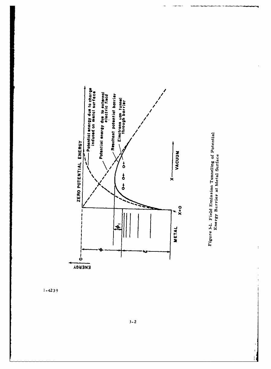
The primary prebreakdown conduction process in vacuum is field
emission of electrons from the negative electrode (cathode). When a high
electric field is applied to a vacuum-metal interface, the surface potential
energy barrier is thinned sufficiently so that free electrons in the metal can
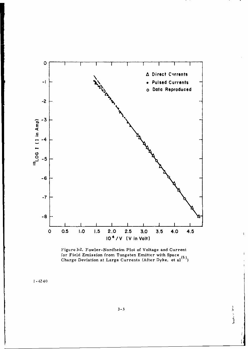
tunnel through and escape into the vacuum (see Figure 3-1). Fowler and Nord-(4).
heim, in 1928, derived the following equation to describe field emission:
I A E 2 -B/E=AE e (1)
where:
E = Electric field strength
A Constant, depending on emitting area
B = Constant,depending on work function 4 of the metal surface
The exponential term is dominant, and a typical voltage (field-current)
measurement of field emission from a tungsten needle which had been etched
to a very sharp point is given in Figure 3-2. Appreciable currents are pro-
duced by fields of the order of 3 x 10⁷ volts/cm. In the normal vacuum break-
down experiment with broad area electrodes, field emission currents appear
at macroscopic fields around 105 volts/cm. This disparity is resolved by
introducing a field enhancement factor P which raises the mean field (givenV
by F ) to the true field at the emitting site. In some cases, this enhancement
3-1
-04
b. b
VZ 0b - d.. G
.5. 4 S
-*'U2
0a. a
0
0Loo N
0c0Iw
3-2.
0 [ A Direct Ctrrents
S-I - Pulsed Currents
o Data Reproduced
-2
-3 Na._
-- 4
00
-6
-7
-8. ... iIiI I I I II
0 0.5 1.0 1.5 2.0 2.5 3.0 3.5 4.0 4.510 4 /V (VinVolt)
Figure 3-2. Fowler-Nordheim Plot of Voltage and Current
for Field Emission from Tungsten Emitter with Space (5)Charge Deviation at Large Currents (After Dyke, et al
1-4240
3-3
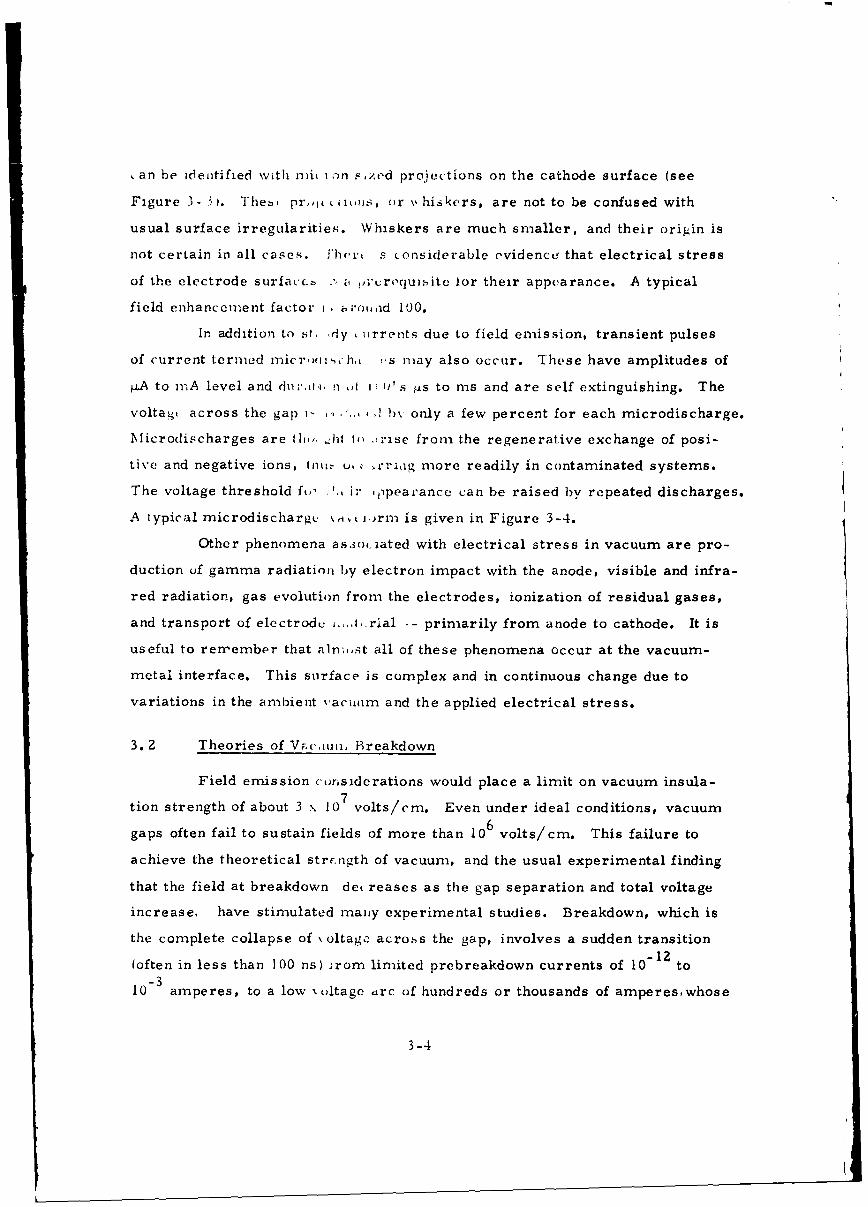
,an be identified with ni i -)n ,>zed projections on the cathode surface (see
Figure 3- 3 ,. Theb, pr.,,ji ( iims, or \4 hiskers, are not to be confused with
usual surface irregularities. Whiskers are much smaller, and their origin is
not certain in all cases. Yhert s considerable evidenc. that electrical stress
of the electrode surfac-•. .' a,;croquisite lor their appearance. A typical
field enhancement factor i zroutd 100.
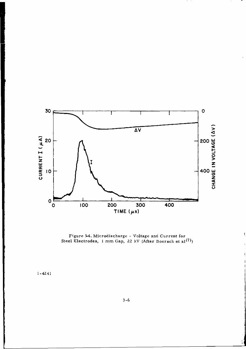
In addition to st. dy ,irrents due to field emission, transient pulses
of current termed i-icrr,,,,h., s nmay also occur. These have amplitudes of
iLA to nmA level and dnr:.,ri, nI ii s ts to ms and are self extinguishing. The
voltag, across the gap ,, (,I by only a few percent for each microdischarge.
\Iicrodischarges are tfli,,. hi to irise from the regenerative exchange of posi-
tive and negative ions, tntt.- u, . critig more readily in contaminated systems.
The voltage threshold fo,, .',, ir ppea,'ance can be raised by repeated discharges.
A typical microdischarg. %,it )rnm is given in Figure 3-4.
Other phenomena as.3ociated with electrical stress in vacuum are pro-
duction of gamma radiation by electron impact with the anode, visible and infra-
red radiation, gas evolution from the electrodes, ionization of residual gases,
and transport of electrod _...1,.rial -- primarily from anode to cathode. It is
useful to remember that alnmst all of these phenomena occur at the vacuum-
metal interface. This surface is complex and in continuous change due to
variations in the ambient vactum and the applied electrical stress.
3. 2 Theories of Vac.nm, Breakdown
Field emission c'orsiderations would place a limit on vacuum insula-
tion strength of about 3 x 10⁷ volts/cm. Even under ideal conditions, vacuum
gaps often fail to sustain fields of more than 106 volts/cm. This failure to
achieve the theoretical strr.nigth of vacuum, and the usual experimental finding
that the field at breakdown det reases as the gap separation and total voltage
increase, have stimulated many experimental studies. Breakdown, which is
the complete collapse of \ oltagc across the gap, involves a sudden transition
(often in less than 100 ns) Irom limited prebreakdown currents of 10 12to
10-3 amperes, to a low x ,ltage trc of hundreds or thousands of ampereswhose
3-4
Figure 3-3. Microprojection (Whisker) Produced AfterElectrically Stressing on Optically Flare Stainless
Steel Surface (after Little and Whitney( 6 ))
2-1410
3-5
30 0
•20 200 w
0!,- -
z >w zir -"i 10 -- 400 w
C.) z
C.)
00 100 200 300 400
TIME (pLs)
Figure 3-4. Microdischarge - Voltage and Current forSteel Electrodes, 1 mm Gap, 22 kV (After Boersch et al(7))
1-4241
3-6
magnitude and duration are limited only by the external electric circuit. A
wide variety of mechanisms have been proposed in attempts to explain practical
experience with vacuum insulation. These reluce, essentially, to three m.ajor
types of instability mechanisms for explaining vacuum breakdow, n.
(8,Q)3.2. 1 Field Emission
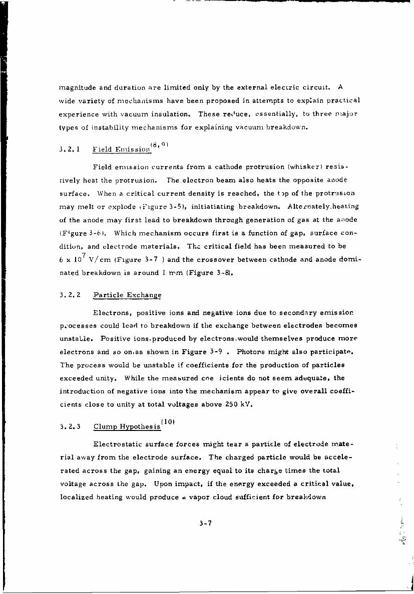
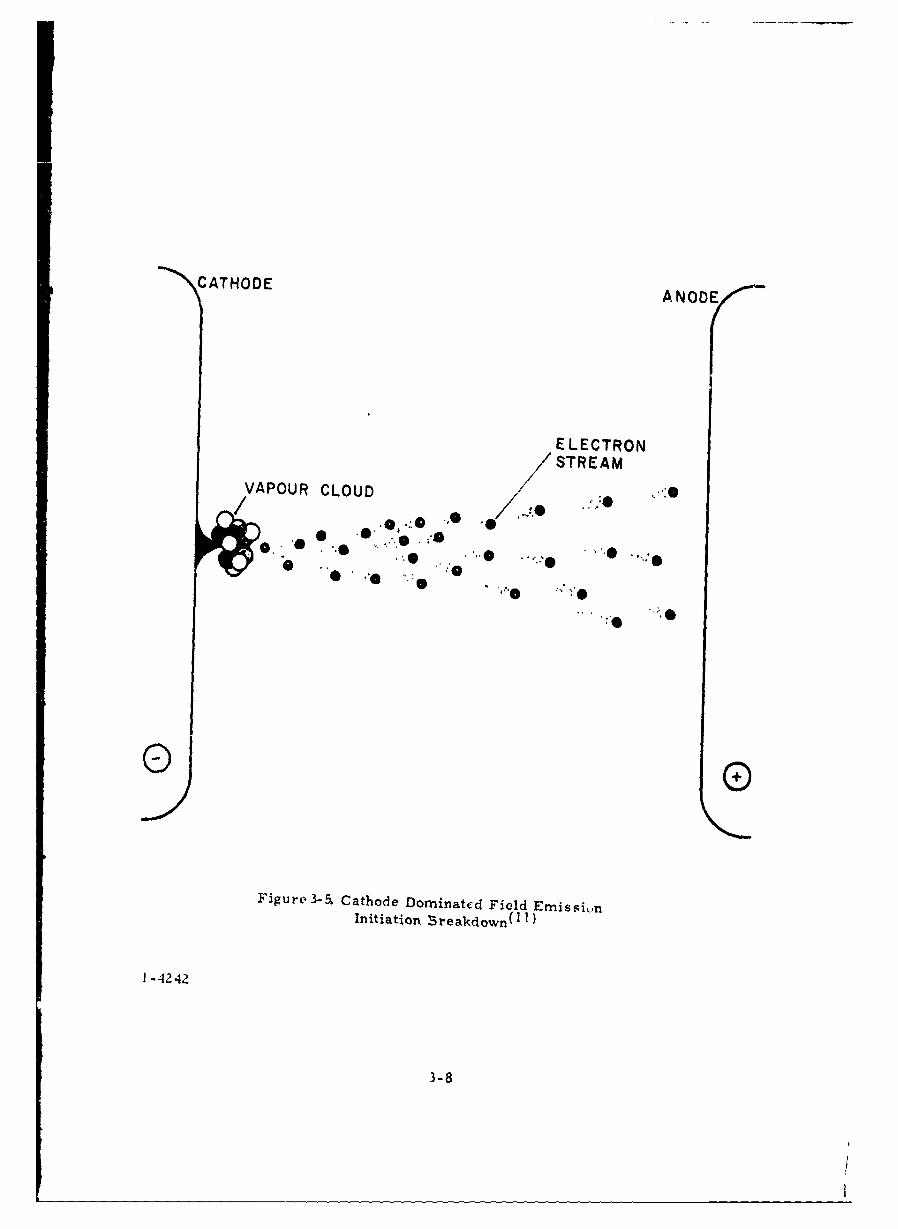
Field emission currents from a cathode protrusion (whisker) resis-
cively heat the protrusion. The electron beam also heats the opposite anode
surface. When a critical current density is reached, the tp of the protrusion
may melt or explode tFigure 3-5), initiatiating breakdown. Alternatelyheating
of the anode may first lead to breakdown through generation of gas at the anode
(F~gure 3-6). Which mechanism occurs first is a function of gap, surface con-
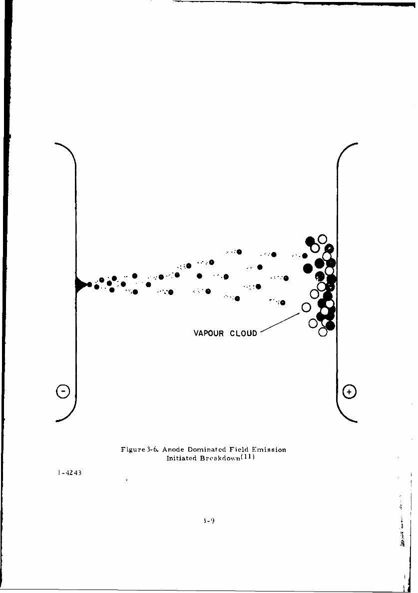
dition, and electrode materials. The critical field has been measured to be
6 x 10⁷ V/cm (Figure 3-7 ) and the crossover between cathode and anode domi-
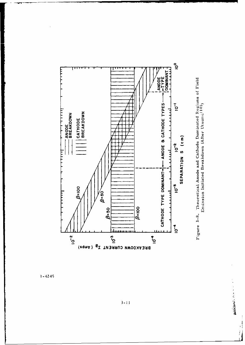
nated breakdown is around 1 mm (Figure 3-8).
3. 2. 2 Particle Exchange
Electrons, positive ions and negative ions due to secondary emission
processes could lead to breakdown if the exchange between electrodes becomes
unstable. Positive ions,produced by electronswould themselves produce more
electrons and so onas shown in Figure 3-9 . Photons might also participate.
The process would be unstable if coefficients for the production of particles
exceeded unity. While the meabured coe icients do not seem adequate, the
introduction of negative ions into the mechanism appear to give overall coeffi-
cients close to unity at total voltages above 250 kV.
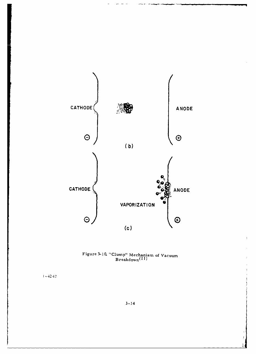
3.2.3 Clump Hypothes is(1 0 )
Electrostatic surface forces might tear a particle of electrode mate-
rial away from the electrode surface. The charged particle would be accele-
rated across the gap, gaining an energy equal to its charge times the total
voltage across the gap. Upon impact, if the energy exceeded a critical value,
localized heating would produce a vapor cloud sufficient for breakdown
3-7
"CATHODE ANODE
ELECTRON
STREAMVAPOUR CLOUD . '• ~0 .... .. :
0 0
"0 *"0 "" 0
0 0
Figure 3-a Cathode Dominated Field Emissi1 ,nInitiation Breakdown(" I)
1 -4242
3-8
I
"0 " *; 'o 0
.00
*0-
0VAPOUR CLOUD
0 0
Figure 3-6. Anode Dominated Field EmissionInitiated Breakdown( 11)
1-4243
- 9 ,
I 0L(L
CE) 0
do 0
0
co CI
0.
Oo0. -
co w T
00
0 -0 .a
ci 0-
4 C4
Co .40 4)
- .4
013.4
10
.54
(W*/SIIOA) 03 (3131A NMOG)IV31dg
1-4244
3-10
0
il y I I I 1 0 • I ! I I I
zz
0W WO
L&J 00ý
0
1-1
(JN In 'y
~0 w0 0
/ Y. 0 c
z.: c / / <i 0o_
.,a,,) I I tt y U .3" O~ •-. I I I /
3- I-- ~ ~ 01 V.1 lt0~ 0 -,I/" y> 0• o U) 41
z V ,)1/1 4_ ,SI•. • "0
00 u
to 0 00
a. 1-f45
if- 11 0
101

PHOTON
ELECTRON-O -- 0- -O--- 0 -- •-
I;:.-•' -
" POSITIVE ION
SECONDARY
ELECTRONS
0 09
Figure 3-9. Elementary Particle Exc., ange Mechanismof Vacuum Breakdown(l 1 )
1-4246
3-12
(Figure 3-10. For uniform field configurations, the predicted dependence of
breakdown voltage upon gap i6 V = kdl/2;" this is often observed at large gaps
(>5 mm) and high voltages (100 kV) as shown in Figure 3-11, and was observed
throughout the experimental program.
3.2.4 Discussion
At small gaps (- I nim) and voltages below 100 kV, field emission ini-
tiation of breakdown ha6 con,' iderable theoretical and experimental support.
At larger gaps and higher voltage, there is little agreement as to precise mech-
anisms, with all three theories having some support. In order to explain ex-
perinmental results it is usually necessary to elaborate and sometimes combine
the above theories. A,, additional difficulty arises because the physical parame-
ters used in the theories (suC h as work function, surface structure, etc. ) are
not subject to direct observation. Thus,it is often difficult to apply any of the
theories in a practical situation.
3.3 References
(1) Proceedings of the First International Symposium on the Insulation of
High Voltages in Vacuum, MIT (October 1964).
(2) Proceedings of the Second International Symposium on Insulation of
High Voltages in Vacuum, MIT (September 1966).
(3) Proceedings of the Third International Symposium on Discharges and
Electrical Insulation in Vacuum, Paris (September 1968).
(4) Fowler, R. H. and Nordheim, L., Proc. Roy. Soc. 119, A, p. 173
(1938).
(5) Dyke, W. P. and Trolan, J. K., Phys. Rev. 89, 799 (1953).
(6) Little, R. P. and Whitney, W. T., J. Appl. Phys. 34, 2430 (1963).
(7) Boersch, H., Hamisch, H. and Wiesner, S. Z. angew., Phys. 13,
450 (1961).
3-13
CATHODE ANODE
CATHODE ANODE
VAPORIZATION
0 0
(c)
Figure 3-10. 'Clump" Mechanism of vacuumBreakdown(1 1)
1-4247
3-14

-0
0~0 H
E) >5
0 w\2I 4)oX
(0 ~ 0
a.0C ~w -
0 CL
0 I06-,
0
0 0 0
(t,Ol X WO/A) SS38.LS Nmoa)1V3J81 3SVMI3AV(Al) 39V.L1OA Nmoa>f V3 81
1-4248
3-15
(8) Alpert, D. , "Electri( il Breakdown in Ultra-High Vacuum", The
Twenty-Sixth Annual Conference on Physical Electronics (March 1966).
(9) Utsumi, T. , "Physical Processes in Electrical Breakdown in Vacuum,
Tech. Report No. 1, ADC-TR-66-712. Cornell University (January 1967).
(10) Cranberg, L.., J. /ppl. Phys. 23, 518 (1952).
(11) Hawley, R., "The Electrical Properties of Higi, Vacuum, " Chapter
4 in High Voltage Tcr:.t ,0ogy, Ed. L. L. Alston, Oxford University
Press, London (1968).
3-16
4. FACTORS IN VACUUM INSULATION BETWEEN
METAL ELECTRODES
4. 1 Introduction
Practical utilization, and indeed, successful controlled experimenta-
tion depends to a large extent on awareness of all the factors which influence
the performance of a physical system. In vacuum insulation, this is especially
true; much of the unreliability and divergence of data commonly encountered is
due to incomplete specification of the important parameters. Therefore, it is
worthwhile to consider the entire range of factors in an organized manner.
Table 4-1 gives a classification of factors known to be critical in vacuum in-
sulation. Inflexible factors are ones which can be varied only during construc-
tion of the insuiztion system; flexible factors can normally be varied during
testing and operation.
These factors cannot be considered independently of one another. In
vacuum insulation the effect of one important factor generally depends upon
the state or level of the other factors. For example, in the experimental pro-
gram it was found that final processing in terms of vacuum or hydrogen firing
would raise or lower the breakdown voltage as a function of electrode material,
electrode shape and size, and the gap. The existence of such interactions
means that simple prescriptions for achieving high breakdown voltages are
very difficult, if not impossible. Thus, in any given situation careful considera-
tion of all the pertinent factors is a requisite, and, even then,experimentation and
tests may well be required to obtain optimum performance. Because of these
interactions the factors are presented or considered in groups. For example,
the influence of the external electric circuit is so closely related to conditioning
that one cannot be adequately analyzed without the other.
4.2 Electrode Material
Electrode material is most important, with both anode and cathode
material having an influence. In high energy discharge cases, the anode mate-
rial is especially critical; this is discussed in section 4. 3. An approximate
4-1
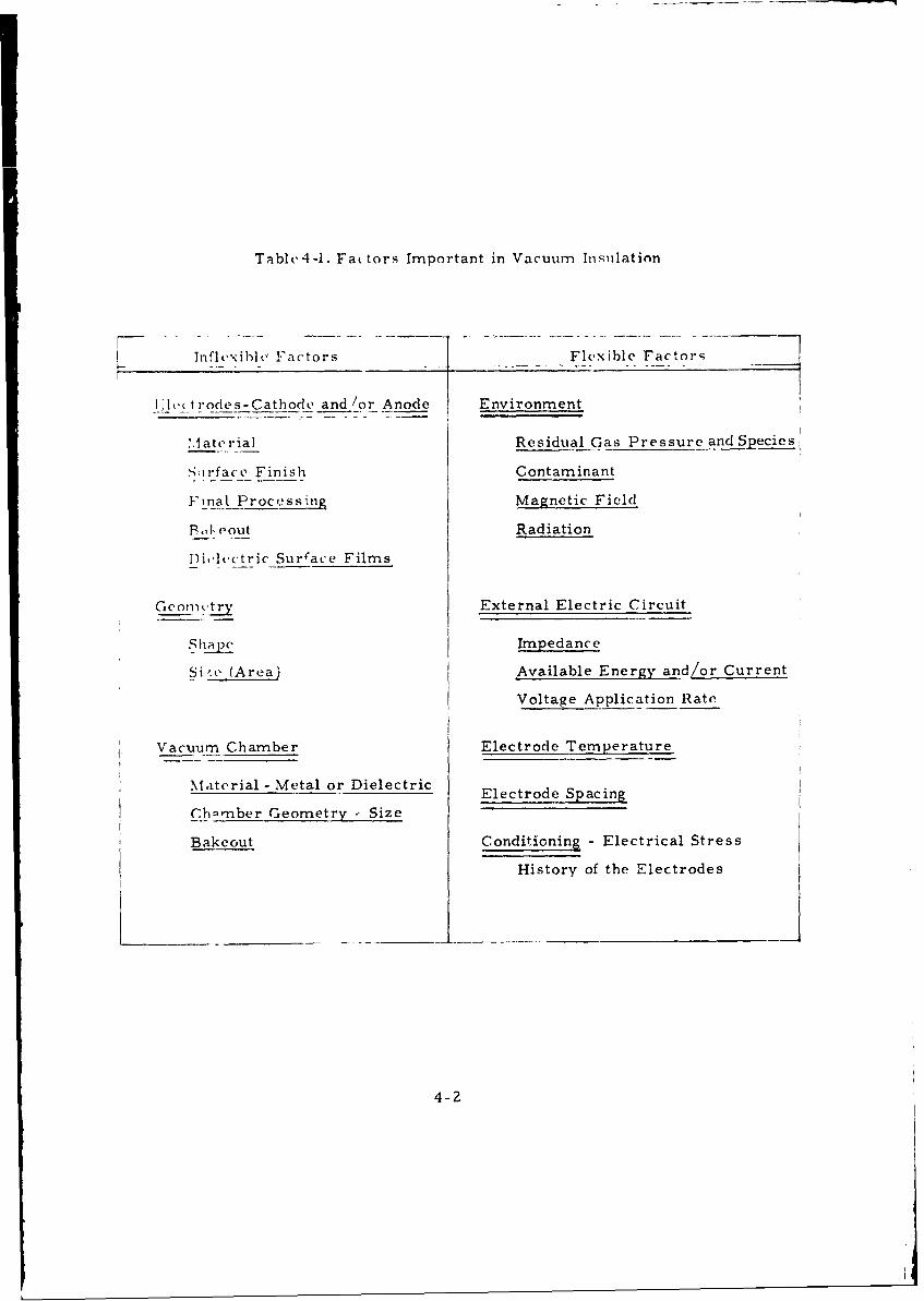
Table 4-1. Fa( tors Important in Vacuum Insulation
Inflcxibl(' Factors Flexible Factors
_:l,,trodes-Cathode and/or Anode Environment
M1 aterial Residual Gas Pressure and Species!
Sirface Finish Contaminant
Final Processing Magnetic Field
P', (,out Radiation
Di,.le.ctric Surace Films
Geomnctry External Electric Circuit
S hap Impedance
Si'. (Areai Available Energy and/or Current
Voltage Application Rate
Vacuum Chamber Electrode Temperature
Material - Metal or Dielectric Electrode Spacing
Ch.rnber Geometry - Size
Bakeout Conditioning - Electrical Stress
History of the Electrodes
4-2
ranking in order of increasing excellence is:
C, Be, Pb, Al, Cu, Ni, Fe, SS, Ti, Ta, Mo, W
Consistent and reliable performance of these metatls os vacuum insulation elec-
trodes requires that 1011,%, and/or standard raw stock be used.
However, a more dtailed examination of the electrode material in-
fluence in vacuum breakdown in practical situations reveals the important role
of interactions with surface finish, final processing, and bakeout. Surface
finish is in itself of mninor importance, but can appreciably affect the degree of
cleanliness that is achieved. For example, the use of oils and buffing com-
pounds in giving the elect.:ode surfaces their final finish has been found to leave
behind organic contamination that is practically impossible to remove. Thus,
it is recommended that finishing techniques such as the use of abrasive paper
\% ith water be considered. In the "High Voltage Breakdown Study" a 600 grit
finish was found to be adequate,in that the performance achieved with it was
indistinguishable from that achieved with 1. 0 micron finish.
Final processing includes cleaning and,for optimum performance,
some form of heat treatment in a controlled atmosphere that stabilizes the
gas content and surface properties of the electrodes. In the experimental
program,both vacuum and hydrogen firing were found to be useful, with tem-
peratures up to 900 'C.
After as sembly of the system, e.g., modulator tube (with care being
taken to avoid dust particles which are detrimental to high withstand voltags),
evacuation and bakeout should be carried out. While the latter is not essential
and sometimes impossible, it is beneficial, both in terms of increased break-
down voltages and consistency of results.
Often, due to system requirements not direccly related to the insula-
tion of high voltages, different materials are used for cathode and anode. For
example, in most high power vacuum tubes copper is used as the anode,be-
cause of its high thermal capacity and conductivity, while a high temperature
material such as nickel or tungsten is used for the cathode material. It is
important to recognize that, in vacuum breaKdown, material transfer from one
electrode to the other generally takes place. In some cases, but in particular
4-3
when the discharge energy is high, there ir extensive transfer of anode mate-
rial to the cathode. This complicates the interpretation of the factor of elec-
trode material, and introduces that, which causes prime concern in vacuum in-
sulation . - the fact that the properties of a vacuum gap can be expected to
change with use.
4.3 Conditioning
The electrical insulating properties of electrodes in a vacuum are
strongly 'tependent on previous operating history. It is usually found that the
voltage hold-off of electrodes in a vacuum can be substantially improved by
allowing repeated breakdowns or passage of appreciable prebreakdown current.
This behavior is termed "conditioning" and is of necessity a consideration in
any vacuum insulation study or applicaticn. It has also been called aging, spot-
knocking, formation, or training.
Conditioning occurs due to changes in Zhe surface states of the elec-
trodes. These changes may be brought about by: mechanical deformation due
to high electric fields; bombardment of the anode by field emission electron
beams; sputtering of cathode protrusions by ionized residual gases; and pos-
sibly by the energetic impact of charged macroparticles detached from one
electrode by electrostatic forces and accelerated across the gap. In addition,
breakdown is a localized discharge that releases energy which disrupts the
electrode surfaces. The most common conditioning technique isto repeatedly
allow the gap to break down. Each discharge is normally limited in energy
(and peak current) by a high series resistance (of the order of megohms). In
this case, the breakdown voltage rises smoothly to a plateau in from 10 to
100 or more breakdowns.
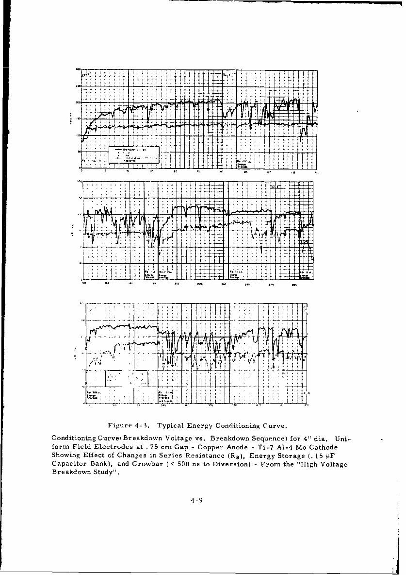
Typical results of conditioning are shown in Figure 4-1; the anode is
burned, eroded, and melted, while the cathode exhibits craters and deposits of
anode material. These are extreme results of conditioning; with very low
energy discharges the effect of thousands of breakdowns may be invisible to
the naked eye. Figure 4-2 shows the surfaces of a copper anode and cathode
after conxditioning. The anode surface has been etched by electron bombardme, ,
4-4
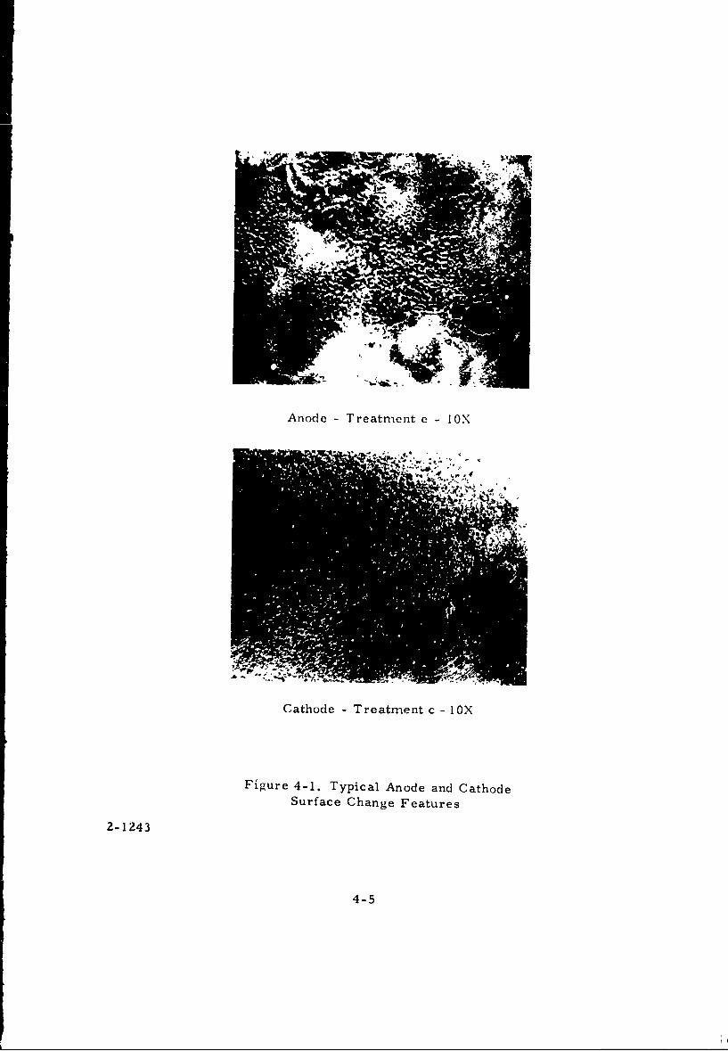
Anode - Treatment e - IOX
Cathode -Treatment c - ox
Figure 4-1. Typical Anode and CathodeSurface Change Features
2-1243
4-5
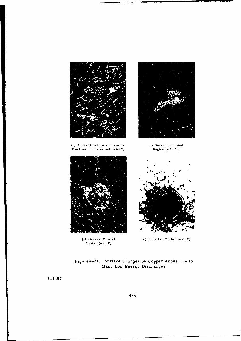
(a) Grain Structure Revealed by (b) Severely Eroded
Electron Bombardment (~ 49 X) Region (~ 40 X)
#
(c) General View of (d) Detail of Crater (- 75 X)Crater (-20 X)
Figure4-2a. Surface Changes on Copper Anode Due toMany Low Energy Discharges
2-1457
4-6
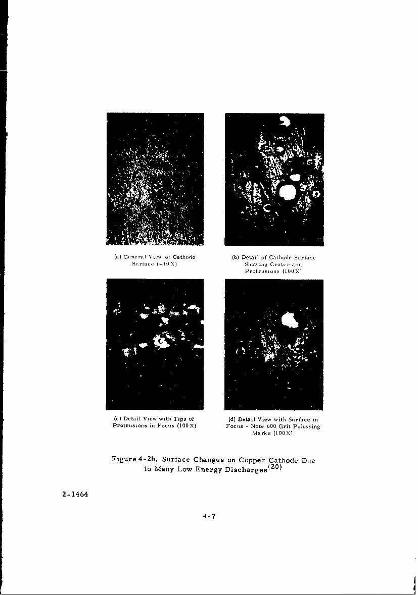
(a) General XVe%% ol Cathode (b) Detail of Cathode SurfaceSurtace' (-IUX) Showing Crater and
Protrusions (IOOX)
(c) Detail View with Tips of (d) Detail View with Surface inProtrusions in Focus (100X) Focus - Note 600 Grit Polishing
Marks (100X)
Figure 4-2b. Surface Changes on Copper Cathode Dueto Many Low Energy Discharges 2 0 )
2- 1464
4-7
revealing the grain structure. '1 he cathode surface was generally undisturbed,
but in the central regions protrusions consisting of transferred anode material
can be seen.
Most high voltage, high power vacuum tubes operate with considerable
energy available to any discharge. Thus, the effect of a spurious breakdown
may be catastrophic, leading to low breakdown voltages, high prebreakdown
currents, loss of vacuum, or mechanical damage. It is generally not economi-
cal to operate high voltage electron tubes at voltages so low that breakdown will
never occur (see Section 4.6). Therefore, the effects of high energy discharges
must be considered. The typical response of electrodes to discharges of differ-
ent energy levels is given in Figure 4. 3 and is discussed in some detail,due to
the importance of the factor of conditioning. A summary of energy conditioning
performance with a copper anode, obtained by using the average values of
breakdown voltage over eight tests, will serve as a basic model.
The average initial breakdown voltage of unconditioned electrodes was
140 kV (187 kV/cm). High impedance conditioning (HIC), i.e., 90 discharges
with 30 kilohms series resistance raised the average breakdown voltage to
200 kV. Prebreakdown current (as indicated in Figure 4-3 by the voltage at
which 10"6 amperes flowed) diminished. The next moderate energy conditioning
(MEC) series of 90 discharges,with 1 k-ohm series resistance and 0. 15 4F
capacitive energy storage, reduced the average breakdown voltage to 187 kV,
and the scatter, as measured by the standard deviation, increased from 4. 5%
for HIC to 14% for MEC. Prebreakdown current levels, however, were not
appreciably affected by the increase in discharge energy.
Next,a limited number of high energy discharges (series resistance
0 ohms at the high voltage bushing, 25 ohms at the 0. 15 4F capacitor bank)
sharply reduced breakdown voltage, increased scatter, and led to very high
prebreakdown current levels. The overall average breakdown voltage was
145 kV, with occasional values as low as 35 kV. Subsequent reconditioning with
moderate energy discharges brought the average breakdown voltage to 201 kV.
High impedance conditioning with energy storage produced little scat-
ter ( (T <4%) and high average levels of breakdown voltaige (220 kV',
4-8
-00
i- .,A
*I• ,... k ' ' .. . . -.-4 ,
'° _ _ _ _ __, _ _ _ • , ; i I I I • i i + '. : i , : i , • I - -. ,-T r T- --
so -69 so0 99 .0 Ml is$£9 4
Sio
.... ..
Figure 4-3. Typical Energy Conditioning Curve.
Conditioning Curve(Breakdown Voltage vs. Breakdown Sequence) for 4"' dia. Uni-form Field Electrodes at . 75 cm Gap - Copper Anode - Ti-7 Al-4 Mo CathodeShowing Effect of Changes in Series Resistance (Rs), Energy Storage (.15 LF
Capacitor Bank), and Crowbar ( < 500 ns to Diversion) - From the "High VoltageBreakdown Study"'.
4-9
Measurements of the breakdown current pulse showed that a series impedance
of 30 k-ohms was sufficient to isolate the gap from capacitive energy storage
in the power supply circuit. A second high energy discharge series reduced
the average breakdown voltage to 151 kV; however, high impedance conditioning
quickly restored the breakdown voltage to the former level of 200 kV. Fast
crowbarring (diversion within 500 ns) with 125 ohms series resistance and
0. 15 tF energy storage was only partially effective and the average breakdown
voltage dropped by 10% to 201 kV with the scatter increased to 15%. Thus,
significant damage occurs within the first microsecond of the discharge.
Simultaneous measurement of discharge current and gap voltage
showed thatthe current rose rapidly (> 2 x 10¹⁰ A/s) with relatively slow col-
lapse of voltage across the gap (about 100 ns for 0. 75 cm gap ).
Thus the initial phase of the discharge appears to have a high impedance ('
1000 ohms). This accounts for the observation that most of the discharge
damage occurs during the first microsecond.
A copper anode opposite a nickel cathode progressively deteriorates
as a result of 220 high energy discharges. The average breakdown voltage
drops from 220 kV to 140 kV and the prebreakdown current increases (voltage
for 10-6 amperes decreased from - 160 kV to - 60 kV). The basic factorial
study was extended to include anode material as a factor at six levels (Cu, SS,
Ni, Pb, Al and Ti-7 Al-4 Mo). Differences in breakdown voltages for the
various materials was minor for low and moderate energy discharges, but
major differences were found with high energy discharges.
Copper, aluminum and lead anodes deteriorated in insulating ability
as a result of high energy discharges. Stainless steel (type 304), nickel, and
Ti-7 Al-4 Mo anodes, after the usual sharp drop in breakdown voltage, upon
introduction of high energy discharges, soon conditioned to breakdown voltage
levels higher than before high energy conditioning. Cathode material was not
important and a copper cathode opposite a Ti-7 A1-4 Mo anode held 300 kV
across a 0. 75 cm gap. Examination of typical electrodes revealed an exten-
sive transfer of anode material to the cathode as discrete droplets and a con-
densed film. The anode surface was severely melted and eroded.
4-10
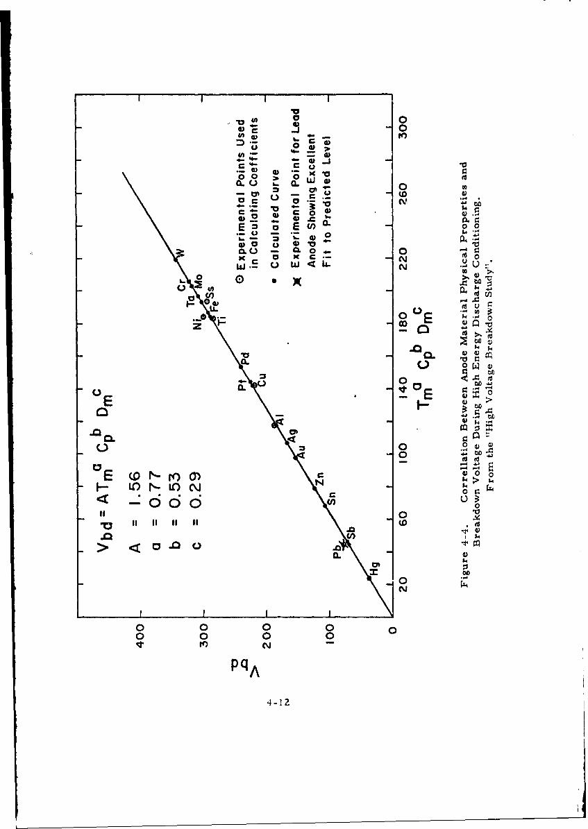
Linear multiple regression analysis was used to correlate physical
properties of anode material with the maximum breakdown voltage during an
extended high energy discharge series for anodes of copper, aluminum, nickel,
Ti-7 Al-4 Mo, and 304 stainless steel. The cathode in most cases was Ti-7 Al-
4 Mo. Melting point temperature, specific heat and density were found to give
the most reasonable fit (index of determination > 0.95) as shown in the curve of
Figure 4-4. A maximum breakdown voltage of 72 kV was predicted for a lead
anode, the experimental value was 76 kV.
This curve provides a way of ranking the performance of anode mate-
rials for high energy applications. The curve uses maximum breakdown vol-
tages - average and minimum values follow the same trends.
The observation that significant damage occurs during the first micro-
second means that protection of the vacuum gap by series impedance or crow-
barring must limit the energy flow very rapidly. Thus, crowbarring for diver-
sion within 500 ns was not fast enough to adequately protect the electrodes in
the experimental study. Addition of inductance, or more series resistance,
would slow the energy input enough so that crowbarring in times of the order
of a microsecond should be effective.
The energy conditioning behavicr described above, especially the criti-
cal dependence on anode material, suggests a breakdown mechanism in which
the thermal interaction of field emission beams with the anode surface is im-
portant. It has been suggested that breakdown might occur when a metallic
particle is eletrostatically extracted from a region of the anode which has been
weakened due to field emission beam heating. The extracted particle is accele-
rated across the gap in the beam, partially vaporized while in transit, and
finally its energetic impact on the cathode precipitates breakdown.
In summary, high energy discharges can be endured by a vacuum gap
without permanent damage. Refractory anode materials are especially tolerant
of high energy discharges. The close correlation between thermal properties
of anode material and breakdown voltage provides a practical means of ranking
anode materials,and estimating the breakdown voltage to be expected in high
energy applications.
4-1!
I ' I ' I
00) 0
• ) -.5: 45 T t- -7
oi•>
.0 0 0
c- 0
E E n -
7 0- 04
o 0
c ~0ot
0 0 . to
"0 II I I I - .N
00
000 000
0 0..
co E.
0- 2
.0G. E0
C>
CLC0 a0
E1 r4540
.00
> <~.0.0.14)
0..N 4
0 0 0 0 00 0 0 0
4-12
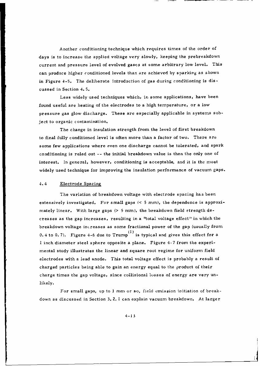
Another conditioning technique which requires times of the order of
days is to increase the applied voltage very slowly, keeping the prebreakdown
current and pressure level of evolved gases at some arbitrary low level. This
can produce higher conditioned levels than are achieved by sparking as shown
in Figure 4-5. The deliberate introduction of gas during conditioning is dis-
cussed in Section 4. 5.
Less widely used techniques which, in some applications, have been
found useful are heating of the electrodes to a high temperature, or a low
pressure gas glow discharge. These are especially applicable in systems sub-
ject to organic contamination.
The change in insulation strength from the level of first breakdown
to final fully conditioned level is often more than a factor of two. There are
some few applications where even one discharge cannot be tolerated, and spark
conditioning is ruled out -- the initial breakdown value is then the only one of
interest. In general, however, conditioning is acceptable, and it is the most
widely used technique for improving the insulation performance of vacuum gaps.
4.4 Electrode Spacing
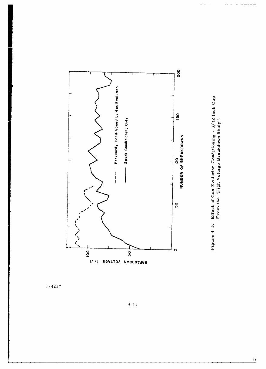
The variation of breakdown voltage with electrode spacing has been
extensively investigated. For small gaps (< 5 mm), the dependence is approxi-
mately linear. With large gaps (> 5 mm), the breakdown field strength de-
creases as the gap increases, resulting in a "total voltage effect" in which the
breakdown voltage increases as some fractional power of the gap (usually from(1)
0. 4 to 0. 7). Figure 4-6 due to Trump is typical and gives this effect for a
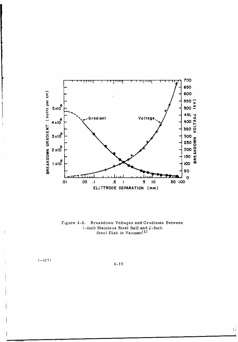
I inch diameter steel sphere opposite a plane. Figure 4-7 from the experi-
mental study illustrates the linear and square root regime for uniform field
electrodes with a lead anode. This total voltage effect is probably a result of
charged particles being able to gain an energy equal to the product of their
charge times the gap voltage, since collisional losses of energy are very un-
likely.
For small gaps, up to ] mm or so, field emission initiation of break-
down as discussed in Section 3. 2. 1 can explain vacuum breakdown. At larger
4-13
0
N
2 sH0
00-~
0444
.c 4
0 C'00
0 0- 0 -0
4- w0 X 0 09
a. 0Iu Q
0.14 .41
0
4.4
I-4
(A4) 0 -
4- -425
4-14
I I I Jil I IIII I I I I 1 700
6500-00
-550O-CL 6 505x10- 00
0 % -45L 'u
4x10 Votg 400
z 350 0W 6>
E; 3xI10 30049
0
0M
.~I XIO- 0
Cr 50
.01 .05 .1 .5 1 5 10 50 100ELECýTRODE SEPARATION (mm)
Figure 4-6. Breakdown Voltages and Gradients Between1- Inch Stainle ss Steel Ball and 2 -Inch
Steel Disk in Vacuum(l)
4-15
CY Q
'4A
00
;4
cdu
14)
ANflwo
.S~
0 '4*p4d
$o40(D
00 0n00 i
10 cl N
0(AM 08AS04)4
94.r4
1-5001 4-16

gaps, and higher voltages, there is presently no commonly accepted and com-
prehensive theory of breakdown. In many instances several mechanisms are
involved, and which happens first or predominates depends upon the experimen-
tal parameters of each situation.
An interesting technique for increasing breakdown voltage by taking
advantage of the high dielectric strength of small gaps is to break the total gap
into shorter sections by means of metal equipotential planes. Ten gaps of
1. 0 mm might vasily withstand 5C kV each for a total of 500 kV, while a single
gap .3f 10 mm cannot be expected to withstand more than 200-300 kV. Of course
some space is lost to the equipotential planes, and, heth in dc and fast pulse
applications, fixing the potential of each plane is difficult. Also, the vastly in-
creased surface area make3 it more difficult to obtain a clean vacuum and
introduces an area effect. However, in applications where potentials of mil-
lions of volts must be insulated by vacuum, as in acceleration tubes, the break-
ing up of the interelectrode space into short segments has beer, found to be
indispensible.
4.5 Electrode Geometry
Electrode geometry in terms of shape and size (area) is more impor-
tant than might be expected. While it is difficult to separate the effects of
area and shape, the general trend is for small areas to support much higher
stresses than large areas - thus, for uniform field geometry,, the breakdown
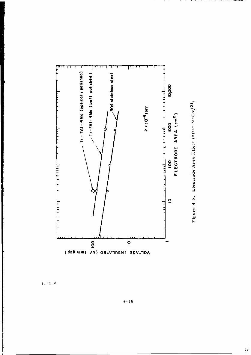
voltage decreases as electrode area increases,as shown by McCoy(2 )
(Figure 4-8). Increasing curvature of spherical electrodes, while producing
a higher maximum stress, reduces the active area so much that the break-
down voltage for a given gap increases, as shown by Rabinowitz( 3 ) (Figure 4-9).
In the experimental study a decrease in electrode area by a factor of ten was
accompanied by a 10-20% increase in breakdown voltage.
A reasonable design criterion for vacuum insulation is to minimize the
highly stressed surface area - even at the expense of increasing the maximum
electric field,
4-17
10 V
CLI
060- 0
. 0 _
o 0 14.
CL 8 a)
4 4J
t 40
00
0 00
(dnb wwI-Af) a3Jiv-nSNI 30VI1O0A
1 -4240a
4-18
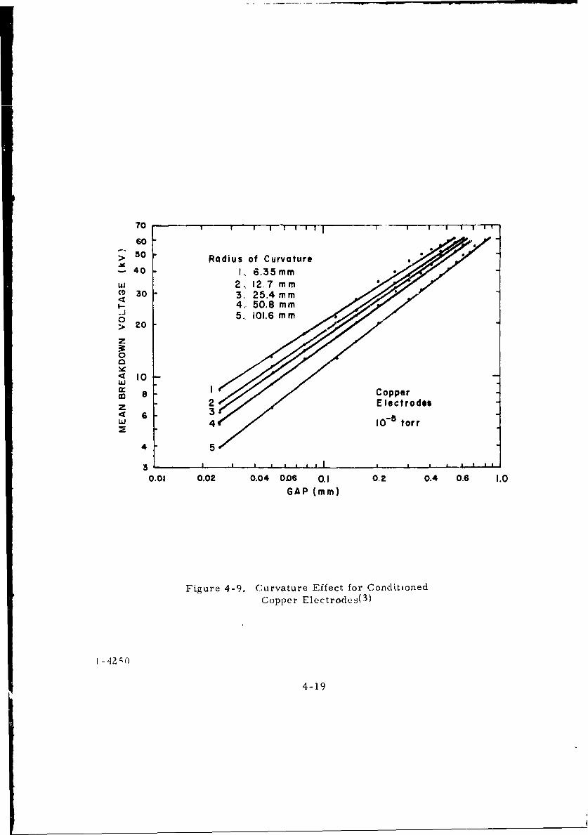
70 " i ii"
6050 Radius of Curvature
-40 1, 6.35 mm,,, 2, 12.7 mmCO 30 3. 25.4mm
•- 4., 50.8 m m"J ~5, 101.6 m m
0> 20
z
0
< Iowix: I Copper
z 2 Electrodes<6 3"W 4 10- torr
4 5
30.01 0.02 0.04 OD6 a.I 0.2 0.4 0.6 1.0
GAP (mm)
Figure 4-9. Curvature Effect for ConditionedCopper Electrodes( 3 )
I - 42;,
4-19
The reasons for an "area" effect have not been conrlusively identified.
One explanation is statistical in nature, postulating that a given unit area has a
certain probability of breakdown, so that the greater the number the more chance
there is for breakdown. Another explanation is simply that it is more difficult
to prepare large surface areas with the same precision and cleanliness as small
surface areas. Yet another, is gas release during voltage application and vari-
ations in pumping conductance.
4. t, Time Effects
Most of the vacuum" insulation studies to date have been for dc voltage
conditions. Recently, however, pulsed voltage applications have increased in
scope and importance. There is every indication that this will continue in the
future. The same is true of ac applications. Some relevant studies are re-
ported below.
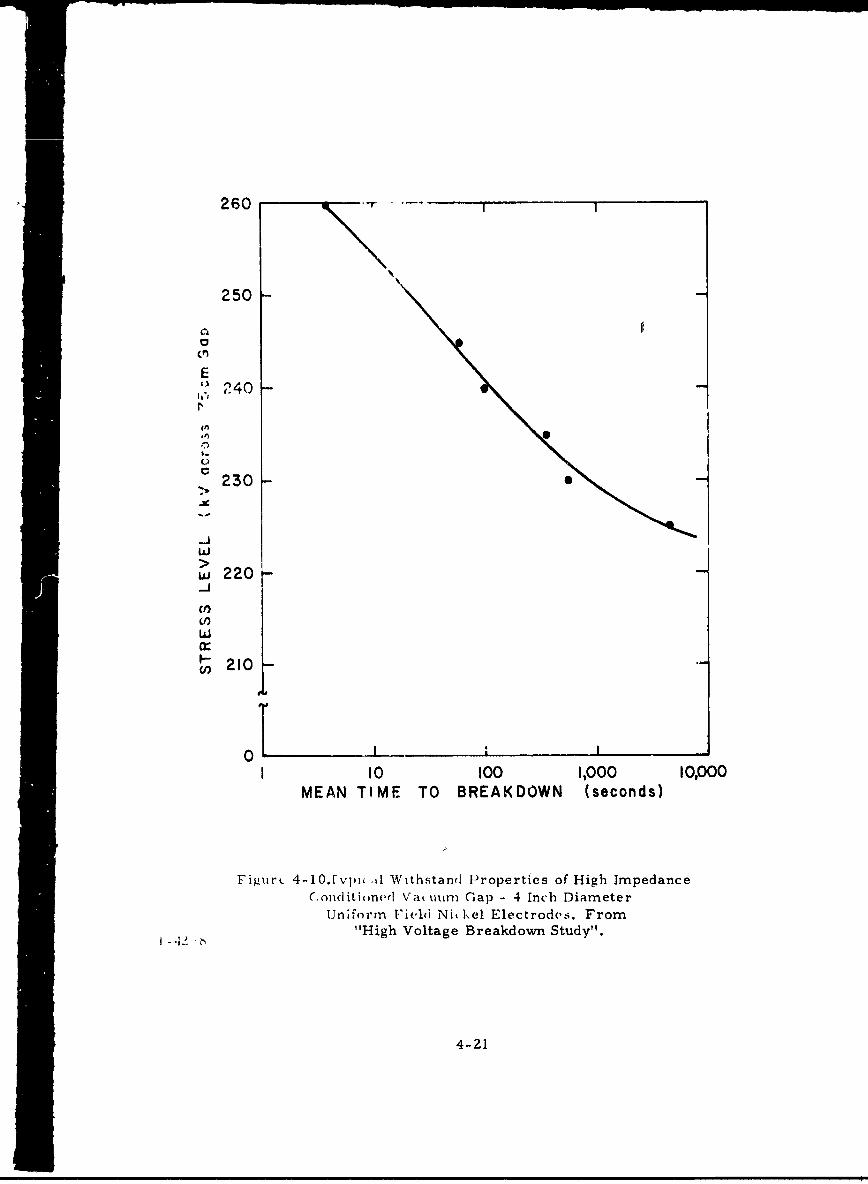
Even in the dc case, time is important since, for a given electrode
system at some stage of conditioning, there is a definite relationship between
breakdown rate and stress level. Thus, Figure 4-10 shows that a 0. 75 cm
uniform field gap will sustain 245 kV if -1 breakdown/minute is acceptable;
whereas it will sustain only 220 kV if there is a requirement for zero break-
down in a time period of many hours. This is for the case of continuously
applied voltage.
Time is also important, even when there is no electric stress on the
electrodes. In most vacuum systems or tubes long periods of time (hours to
days ý without electric stress will result in de-conditioning of the electrodes.
Then,some degree of conditioning will be required to again reach previous
operating voltage levels.
Impulse breakdown in the microsecond range has been investigated
at up to 500 kV by Smith{4 ) with 1/4000 4s pulses. Breakdown was found to
occur in either an abrupt localized spark after - 20 4s or a diffuse glow-like
discharge with slow current rise, also at about 20 4s. A particle exchange
mechanism is suggested for the second type. Breakdown stress levels in this
experiment were about 100 kV/cm, which is not particularly high, and is
4-20
260 - - -
250
0
E
" 240
V
W2 2 0
-J
210
MEAN TIME TO BREAKDOWN (seconds)
Figiiri 4-1O.1vpiu A1 Withstand Properties of High ImpedanceC.ondlitioned Vat. tum (-ap - 4 Inch Diameter
U~niform 1'ield Nik.kel Electrodvs. From"High Voltage Breakdown Study".
4-21
evidence that the breakdown mechanismn is probably very similar to that found
under dc conditions.
Nanosecond pulse breakdown has recently been extensively studied for
moderate voltages by Wolff(5) and Mesyats. (6) It was established that, for
nanosecond pulses, breakdown is cathode dominated. Breakdown could occur
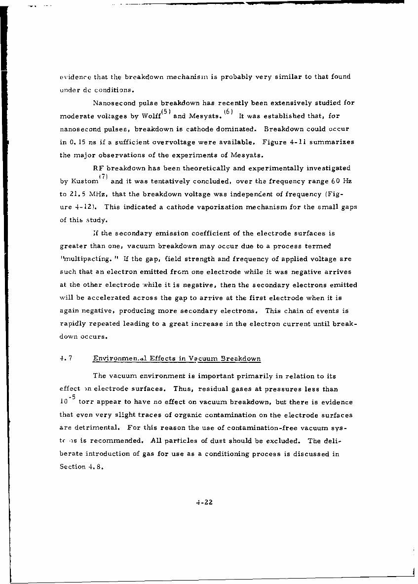
in 0. 15 ns if a sufficient overvoltage were available. Figure 4-11 summarizes
the major observations of the experiments of Mesyats.
RF breakdown has been theoretically and experimentally investigated
by Kustom 7) and it was tentatively concluded, over the frequency range 60 Hz
to 21.5 MHz, that the breakdown voltage was indepencent of frequency (Fig-
ure 4-12). This indicated a cathode vaporization mechanism for the small gaps
of this study.
If the secondary emission coefficient of the electrode surfaces is
greater than one, vacuum breakdown may occur due to a process termed
"fmultipacting. " If the gap, field strength and frequency of applied voltage are
such that an electron emitted from one electrode while it was negative arrives
at the other electrode while it is negative, then the secondary electrons emitted
will be accelerated across the gap to arrive at the first electrode when it is
again negative, producing more secondary electrons. This chain of events is
rapidly repeated leading to a great increase in the electron current until break-
down occurs.
4.7 Environmen..l Effects in Vacuum Breakdown
The vacuum environment is important primarily in relation to its
effect )n electrode surfaces. Thus, residual gases at pressures less than
10"5 torr appear to have no effect on vacuum breakdown, but there is evidence
that even very slight traces of organic contamination on the electrode surfaces
are detrimental. For this reason the use of contamination-free vacuum sys-
tc is is recommended. All particles of dust should be excluded. The deli-
berate introduction of gas for use as a conditioning process is discussed in
Section 4. 8.
4-22
VN NN
III
++
III • I
IV VIII
Current
(Peak= 230 A)
44 iW V2 V7
0 • 19 4 32
Time in ns
Figure4-1 1. Development of Gap Luminosity inNanosecond Breakdown of Vacuum Gaps( 6 )
4-23

2.0 ion Exchange
Ion PerturbationN Ionh n g
N
- Anode Bombardmenti - ,.o {- .... -
C J" Vaporization>
0,AM Experimental Points
0 - , I II I
1. .2 .3 ,4 .5 .6
GAP SEPARATION (cm)
Figure4-1 2 .Comparison of Vacuum Breakdown at
2 1. 5 MHz to 60 Hz for Tungsten Electrodes:Theoretical Curves included( 7 )
4-24

Magnetic field is another environmental factor. In the experimental
study wL.-k magnetic fields (to 500 gauss),transverse to the electric field, had
the effect of slightly lowering breakdown voltage for gaps greater than 1. 0 cm,
and raising the breakdown voltage slightly for smaller gaps. In a study by
Pivovar ac lower voltages, a strong magnetic field was applied which pre-
vented field emitted electrons from reaching the anode. This raised the break-
down voltage,but did not appreciably change the voltage at which microdischarges
(see Section 3. 1) occurred. Thus, there is evidence that magnetic fields will
affect the breakdown voltage of va-uum gaps, but the effects were not strong.
When a dielectric surface is present in the high field regions of the vacuum
system, the effects of a magnetic field are much more severe. This will be
discussed in Section 5.
The environment of a vacuum gap in an electron tube may contain
sources of contamination. For example, the glass walls of a typical tube may
produce small dielectric particles which can induce discharges if they migrate
to the highly stressed electrodes. In many tubes a barium oxide thermionic
cathode is used. High voltage vacuum tubes with a barium oxide thermionic
cathode are usually limited to lower electric stresses than tubes without such
a cathode. (9) This lower operating stress is most probably due to the reduc-
tion in work function of metal surfaces when barium and/or barium oxide is
deposited, which,in turn, leads to higher field emission currents and lower
breakdown voltages. Thus, contamination from a barium oxide cathode is an
important factor in high voltage vacuum tube performance.
Brodie 10) found that barium contamination of nickel electrodes re-
duced the breakdown field,and increased field emission currents by several
orders of magnitude. Conditioning, by low energy discharges at a 0. 5 mm
gap, restored the breakdown field to its original level, but the emission cur-
rent was then greater by a factor of over 15. These rifects were conclusively
related to the deposition of barium on the tips of whiskers,in an experiment
with a cylindrical projection tube. Barium decreased the work function of the
emitting tips and,thus, increased field emission currents. Conditioning,then,.
destroyed the emitting sites which had been rendered unstable by increased
4-25
emission. This explanation is supported by considerable experimental evi-
dence that vacuum brekdown, at a small gap (0.5 mm),is usually due to the
explosive vaporization of field emitting protrusions on the cathode when the
current density exceeds a certain critical value.
In the experimental study electrodes of copper, nickel, stainless steel
and Ti-7 Al-4 Mo were tested at high Voltages. It was found that the effect of
barium contamination of the anode had a negligible effect, but was more serious
for the cathode. Differences among the metals tested were slight.
Initially, for copper electrodes there was only a slight change in break-
down voltage upon exposure. Sixteen hours of exposure to the barium oxide
cathode run at a high temperature resulted in a progressive decline in break-
down voltage as conditiohing proceeded. Prebreakdown currents were erratic
and breakdown usually occurred at less than 10 A. Rapid sparking (several
discharges per second) proved very effective in reconditioning the gap. After
13 exposures to various levels of barium contamination, .ach followed by con-
ditioningthe 10 cm diameter OFHC copper electrode had a breakdown voltage
of 225 kV for the 0. 75 cm gap, with 10-6 A of prebreakdown current at 205 kVi
This- is as good as is found with uncontaminated electrodes.
When-stainless steel (304) and nickel electrodes were subjected to high
energy discharge conditioning (0.15 iF of capacitive energy storage with 25 ohms
series resist wnee), the breakdown voltage initially dropped- but later recovered
to higher values (- 300 kV for a 0. 75 Cm gap) than before high energy discharges.
However, when contaminated from the barium Oxide cathode, these electrodes
were severely and permanently degraded by high energy discharges. This was
due to the poor adhesion of impacted anode particles On the contaminated cathode.
The anode material transferred by breakdown did not remain flat on the cathode
but was pulled away by the electric field to form large ( 1 mm) and sharp pro-
jections, as shown in Figure 4-13.
Barium contamination is potentially a serious problem in vacuum in-
sulation. Proper conditioning can alleviate its bad effects in most cases, but
when high energy discharges occur, barium contamination (and Other types of
contamination as well) may lead to permanent damage due to poor adhesion of
4-26
j,
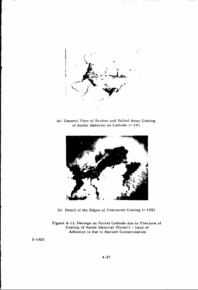
F, /t
S~,#
(a) General View of Broken and Pulled Away Coating
of Anode Material on Cathode (~ 5X)
(b) Detail of the Edges of Fractured Coating (~ 1OX)
Figure 4-13. Damage on Nickel Cathode due to Fracture ofCoating of Anode Material (Nickel) - Lack of
Adhesion is due to Barium Contamination
2-1426
4-27
particles transferred by breakdown from the anode to the cathode.
4. 8 Dielectric Coating of Electrode Surfaces
Thin dielectric films on the cathode surface, if properly applied, can
substantially enhance the insulation performance of a vacuunm gap. A typical
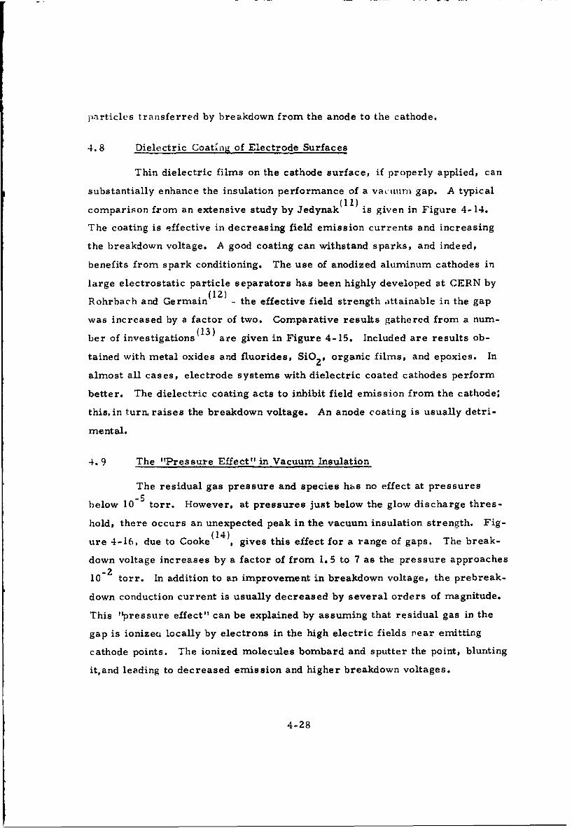
comparison from an extensive study by Jedynak(11) is given in Figure 4-14.
The coating is effective in decreasing field emission currents and increasing
the breakdown voltage. A good coating can withstand sparks, and indeed,
benefits from spark conditioning. The use of anodized aluminum cathodes in
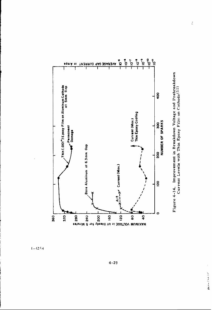
large electrostatic particle separators has been highly developed at CERN by(12)
Rohrbach and Germain - the effective field strength attainable in the gap
was increased by a factor of two. Comparative results gathered from a num-(13)
ber of investigations are given in Figure 4-15. Included are results ob-
tained with metal oxides and fluorides, SiO2 , organic films, and epoxies. In
almost all cases, electrode systems with dielectric coated cathodes perform
better. The dielectric coating acts to inhibit field emission from the cathode;
this, in turn, raises the breakdown voltage. An anode coating is usually detri-
mental.
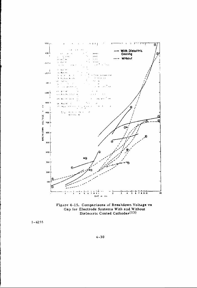
4.9 The "Pressure Effect" in Vacuum Insulation
The residual gas pressure and species has no effect at pressures
below 10°5 torr. However, at pressures just below the glow discharge thres-
hold, there occurs an unexpected peak in the vacuum insulation strength. Fig-
ure 4-16, due to Cooke (14), gives this effect for a range of gaps. The break-
down voltage increases by a factor of from 1. 5 to 7 as the pressure approaches
10°2 torr. In addition to an improvement in breakdown voltage, the prebreak-
down conduction current is usually decreased by several orders of magnitude.
This "pressure effect" can be explained by assuming that residual gas in the
gap is ionizea locally by electrons in the high electric fields near emitting
cathode points. The ionized molecules bombard and sputter the point, blunting
it,and leading to decreased emission and higher breakdown voltages.
4-28
sdWV ulI N36uno 0 dV30VM3AV Q 2- 0 02 '2 '0 '02I 1 111
0
00 -
C b0
E -E
00
Ce.c CL w
0x
L iflL ~ I !
0 0 0 mN 0
m NN u
4-2
- With Dielectric,
4 ". . Coafing..... .. ..- -- - W~thct~t /~ |
P ., -, '
• 1* / * ( , ,1 1 t
h". br A, C. r
000 0 - ,''' ', , . '
a' 'ia '
900, I
II•0 • ' -, ..' " I
C /
Al""C Al
",a/ /
z .
/ ® / • / ."In oo• / 0
o/ / ' ' -
.Cis A )// "--•
A0M / A, - -1/ • ,,s i/-
400 ,L 0,
-- , / ,. s ~/'" r• S * -- -".4
GLP to c,
Figare 4-1 5. Comparisons of Breakdown Voltage vs
Gap for Electrode Systems With and WithoutDielectric Coated Cathodep(13)
4-30
(1) 16 cm dia SS spherica) anode vs.plane SS cathode at 20 cm gap
2(2) 30, 000 cm SS plane anode and
6 cathode at 10 cm gap
(3) 15, 000 cm 2 SS anode15., 000 cm alumina coated0 2cathode-plane system at 5 cm gapJ
> (4) 100 cm SS anode and cathode
Z plane svstem at 2., 5 cm gap
00- > (5) 100 cm' SS anode and cathode
4 I plane system at 1. 0 cm gap
w
1--
0
>
0 n I I
10"6 I0"5 10-4 10"3 1 02 " 0"1
PRESSURE (torr)
Figure 4-16. Pressure Effect for Various Electrode Systems( 14 )
1 -42;6
4-31
(15)
Recently, Ettinger and Lyman have demonstril.ed a "gas condi-
tioning" procedure which can be used to reduce prebreakdown current and
raise breakdown voltage. In this technique, an inert gas is introduced and
prebreakdown currents of 50 ý.A drawn for many hours, with the voltage being
slowly raised. The result is a cathode surface that is more stable,and with
less emission than would be the case for electrodes conditioned by sparking.
Again, the m-echanism is thought to be selective sputtering of cathode protru-
sions. This is similar to conditioning by prebreakdown current used in the
experimental study and discussed in Section 4. 3.
4. 10 Electrode Temperature
The effect of heating the anode or cathode electrode has been investi-
gated by Slivkov (16 with pulsed voltages (1.5/50 4tsec wave). There was no
appreciable affect up to - 400°C. Above this temperature anode heating re-
duced breakdown voltage while cathode heating increased the breakdown voltage.
Improvement in breakdown voltage was less than 20% in general, and reduction
of breakdown voltage at temperatures up to 800°C was not more than 40%.
The prebreakdown field emission currents from the cathode can de-
liver considerable energy to the anode, raising it to high temperatures if it is
not well cooled and the currents are high. For example, in the experimental
study currents of 2 n-•A at 200 kV were not uncommon. The power input to the
anode was thus 400 watts, and under these conditions the anode was heated to
the point of glowing. Even so,the breakdown voltage did not decrease by over
40%. However, in a practical application it would be desireable to insure that
anode cooling is adequate.
Cooling of electrodes to cyrogenic temperatures has been found( 1 7 ' 18)
to decrease prebreakdown currents and increase breakdown voltage. However,
these results were preliminary, and further investigation is necessary before
general substantiation of this method of improving the dielectric performance
of vacuum gaps.
4-32
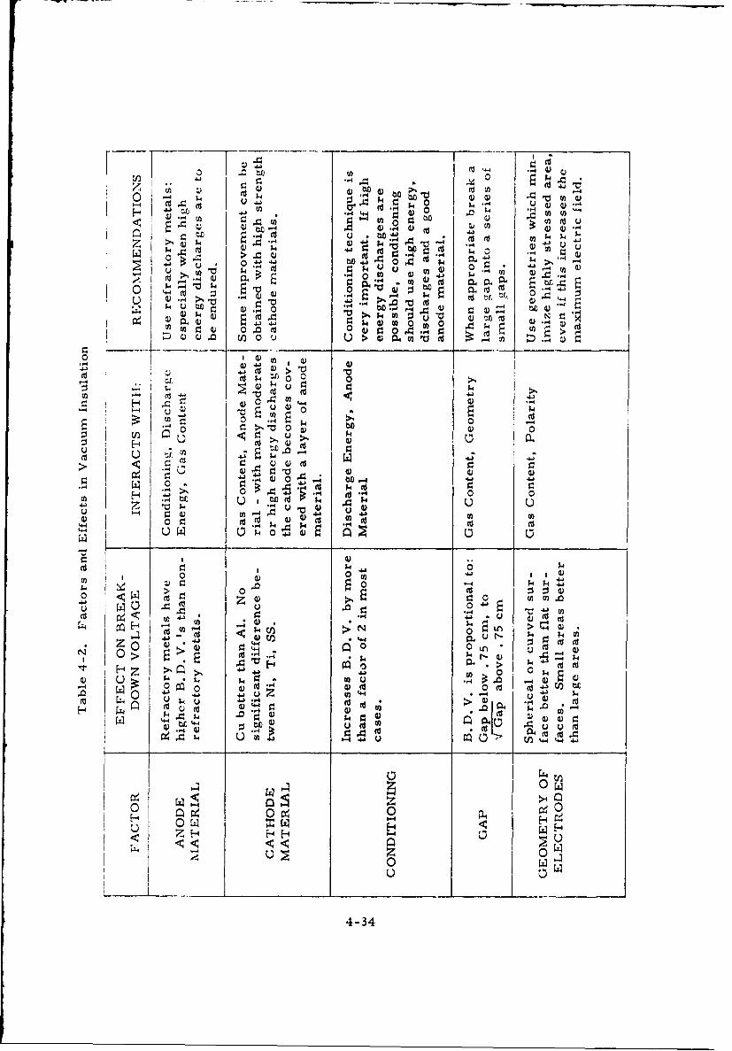
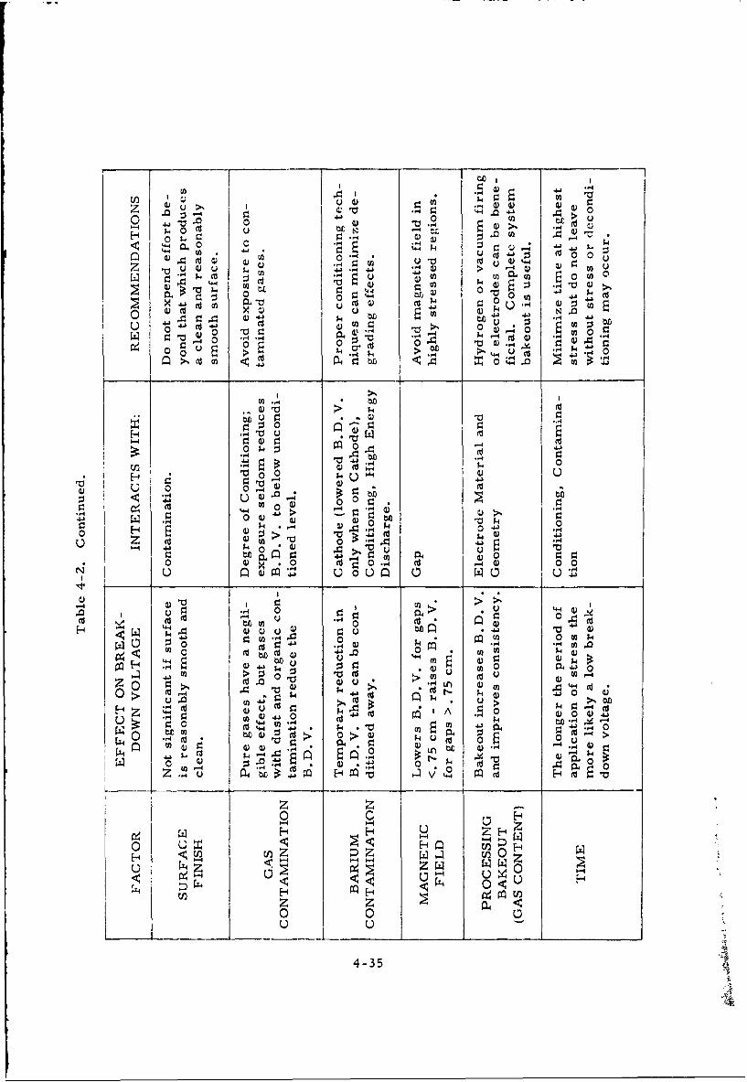
4. 11 Conclusions Regarding Factors in Vacuum Insulation
After many decades of investigation and use, the factors and mech-
anisms important in vacuum insulation are now generally recognized and par-
tially understood. With continued growth in the number and scope of the appli-
cations of vacuum insulation, it can be expected that,in the near future,a more
complete theory of vacuum breakdown will emerge.
Already,the application of dielectric coatings to cathode surfaces
and use of the optimum pressure for vacuum insulation has enabled substan-
tially improved performance to be achieved where these techniques are possible.
The crucial role of conditioning as a means of producing stable elec-
trode surfaces is now receiving critical attention. Many of the new metals
developed for other uses have proved to be excellent for vacuum insulation.
Progress along these lines can be expected to continue, and enable stress levels
of hundreds of kV/cm to be routinely and reliably achieved with vacuum insu-
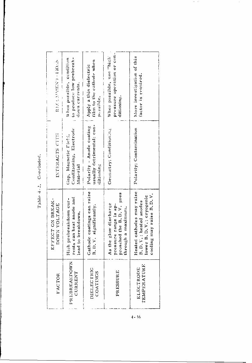
lation. Table 4-2 summarizes the more important factors that have been con-
sidered in this handbook.
4.12 References
(1) Trump, J. G. and Van de Graaff, R. J., J. Appl. Phys. Vol. 18,
No. 3, 327-332 (March 1947).
(2) McCoy, F. J., Electrostatic Generator Quarterly Reports, Contract
No. AF33(615)-1168, Ion Physics Corporation, Burlington, Mass.
(1964).
(3) Rabinowitz, M., Proceedings of the First International Symposium
on Insulation of High Voltages in Vacuum, p. 119, Boston (October
1964).
(4) Smith, W. A., Mason, T. R. and Childs, T. L. K., Proceedings of
The Third International Symposium on Discharges and Electrical
Insulation in Vacuum, p. 203, Paris iSeptember 1968).
4-33
4 -44
to :t ( ( 4) 4
-4 4 ~ - " .- u 0 .$4 U n pu' j
-,4 ,44 E
o0 04"t. (dE v cu0-4 4t, -1
-U4 - -
$4 U u . ,4> 0 d4,4 1.) .-4
4) 0) 40
Q)4 ..V. 04 4)~ u U04W 0 4
41 '1
C %640 4)
-4 P
U ~~ $4U ~ "
*ý. 4o 4)4 0U)4
toU .0 04 0L
r444) o~ X
H, 00
u X. "iz w 41
u p o
4-3
o0- 0. n c -A
0 N2
0ou0
0 ~., U d 40
-0 ;4 0 V0 :j 4J
41 04 0 Cd ) m 0 0 u :
0) c (d n u &4 'a4
4.3 U4) 00
r0 0E 0 c *
0 >)o H in~
- -4
* 0
0 U 4U 0 0Z1g
'0 0""a *- 0 p0 cu u
W 0 (D o
4 'A to )0)ik .~ -4' .* '4 0' 1 .,1
0 Z~ cd0-4H
41 H4 0 o au
0 0 0 .4 (U U a)U-
M4k
C-3
4-1~
C;4 "a
- ~ -4
4j - 4 e I-*
7 - ~ .I--
~ 4.3
L4
.- 4
0 0 0
14-
H En
~ ~ U0- .- ef4. W2 4-
C4 0 H
1~ (U
(U U~ 4
0 0
- ~4~~4- 30
(5) Wolff, H., Juttner, B. and Rohrback, W., Proceedings of the
Third International Symposium on Discharges and Electrical In-
sulation in Vacuum, p. 209, Paris (September 1968).
(6) Mesyats, G. A., Bugacv, S. P., Iskolsdskii, A. M. and Proskurovskii,
D. I. , Soviet P' vsics, Tech. Phys., Vol. 12 (June 1968) (English
Translation).
(7) Kustom, R. L., Proceedings of the Third International Symposium
on Discharges and Electrical Insulation in Vacuum, p. 223, Paris
(September 1968) and "The Electrical Breakdown of Vacuum Insulated
Electrodes Under Radio Frequency Stress, " Proceedings of the 1969
Particle Accelerator Conference, p. 556, Washington, D. C.
(8) Pivavar, L. I., et al, Soy. Phys., Tech. Phys., 2, 909 (1957).
(9) Doolittle, H. D., Machlett Cathode Press, 21, No. 1, pp. 2-15 (1964).
(10) Brodie, I. J., Vacuum Science Technology, _, p. 249 (1965).
(11) Jedynak, L., J. Appl. Phys. Vol. 35, No. 6, 1727-1733 (June 1964).
(12) Germain, C., Jeannevot, L., Rohrback, F., Simon, D. and
Tingnely, R., Proceedings of the Second International Symposium
on Insulation of High Voltages in Vacuum, p. 279, Boston (October
1969).
(13) Bolin, P. C. and Trump, J. G., Proceedings of the Third Interna-
tional Symposium on Discharges and Electrical Insulation in Vacuum,
p. 50, Paris (September 1968).
(14) Cooke, C. M., Proceedings of the Second International Symposium
on Insulation of High Voltages in Vacuum, p. 181, Boston (September
1966).
(15) Ettinger, S. Y. and Lyman, E. M., Proceedings of the Third Inter-
national Symposium on Discharges and Electrical Insulation in Vacuum,
p. 128, Paris (September 1968).
4-37

jf6i Slivkov, In. N., Sov. Phys., Tech. Phys. 4, p. 1359 (1959).
0 7) Looms, J. S. T., Meats, R. J. and Swift, D. A., Brit. J. Appl. Phys.
(J. Phys. D), Vol. 1, Ser. 2 (1968).
f1 I' Do Geeter, D. J. , AEC-NASA Tech. Brief #66-10499 (November 1966).
4-38
5. SOLID DIELECTRICS IN VACUUM INSULATION
5.1 Introduction
Solid dielectrics are almost invariably required in vacuum insulation
systems to support electrodes, or to lead high voltages into the vacuum from
some other insulating medium. In some cases,the vacuum chamber itself is of
a dielectric material. Since the vacuum flashover voltage of a solid dielectric
is much lower than either its volume puncture strength or the breakdown voltage
of an equivalent vacuum gap, the details of solid insulator design and placement
are critical factors in practical systems.
5. 2 Grading and Mechanisms of Flashover
Grading techniques often break the insulating length into short, inde-
pendent and uniformly stressed sections. Thus, the flashover characteristics
of solid dielectrics have been extensively studied only for samples of the order
of 1 to 3 cm long. These are usually placed between uniform field electrodes.
It has been found that the surface discharge originates from the negative junc-
tion of metal, solid dielectric and vacuum. At this "triple point," field enhance-
ment (due to imperfect metal-dielectric contact and the different dielectric
constants of a solid dielectric and vacuum), leads to electron emission; this,
in turn,charges in a non-uniform way,the surface of the solid dielectric;charge
multiplication along the surface may occur; gas may be evolved and ionizes;
finally flashover results.
5.3 Techniques for Increasing Flashover Voltage
Intimate contact between the solid dielectric and the metal electrodes
and proper shaping of the negative junction can raise the flashover voltage of a
given material. The usual techniques rely on either shielding of the negative
triple point to reduce field stress, or on shaping of the insulator to minimize
the deleterious effects of electron emission from the negative triple point.
Figures 5-1 and 5-2 show various shielding methods investigated by Finke(1 )
(2)and Shannon, et al Certain of Shannon's insulator shapes are designed so
5-1
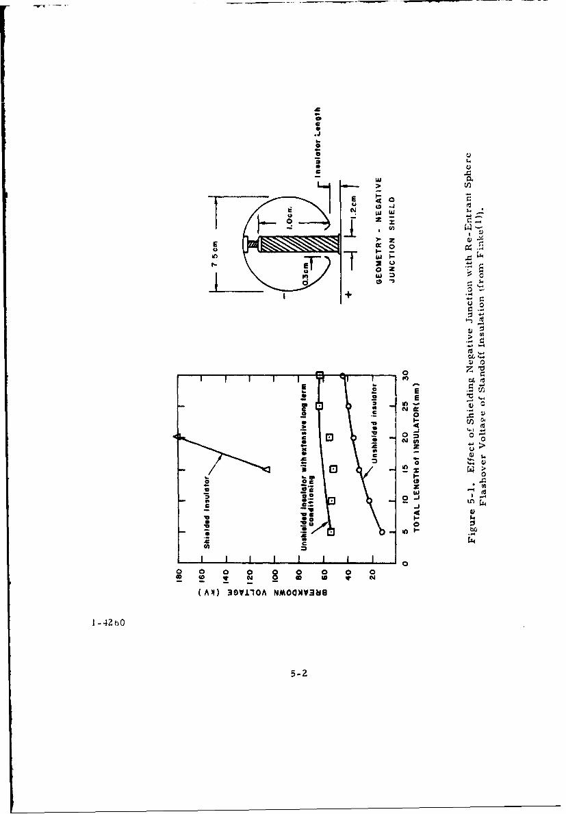
0* 0.)
* 0)
7. w
E E
E. 0 Eo
04100
0 4 0
c 0
0
*p 0
w I
* 0
0 0 0!E *1 C4 8- O *
I - 42 4-
5- 0
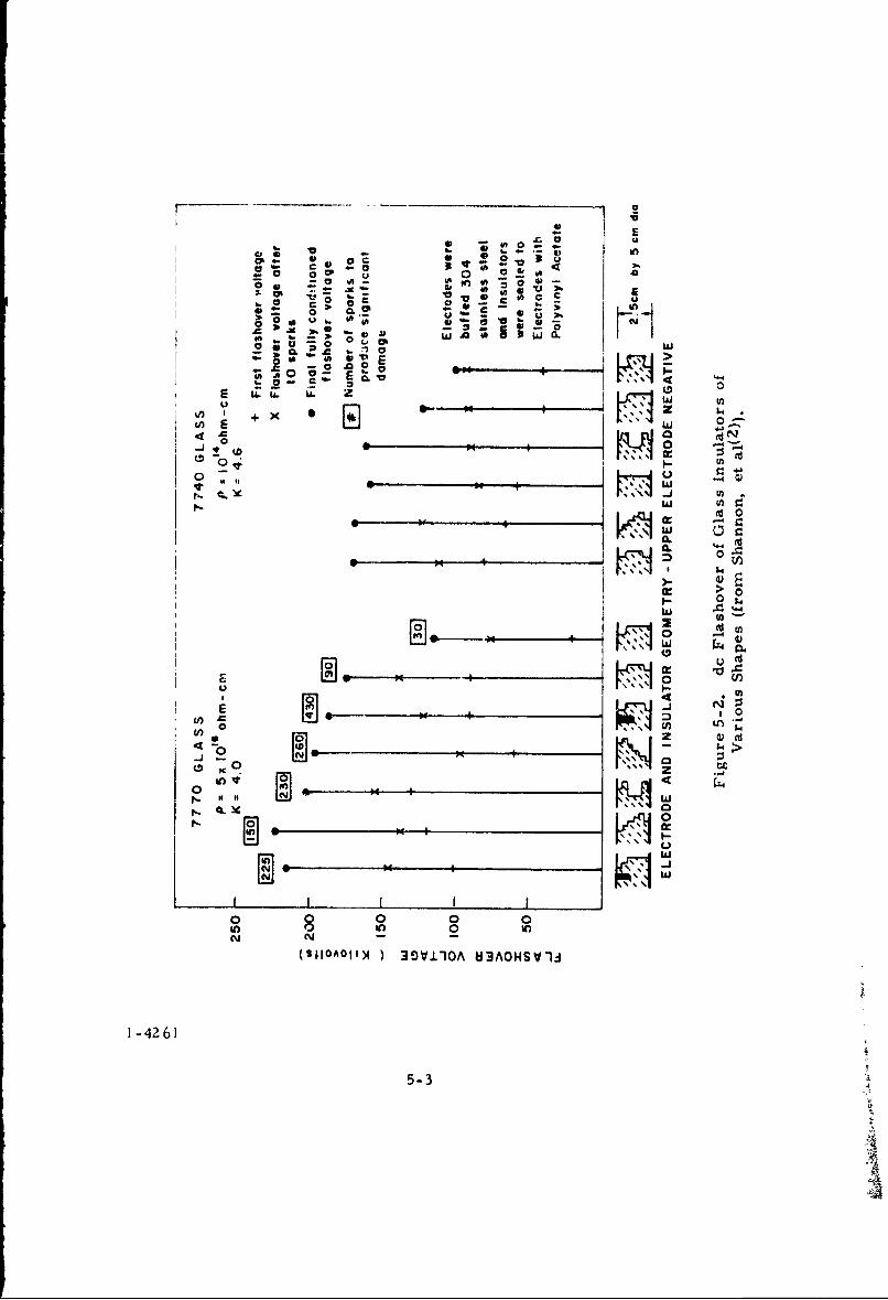
t. -_ __- -- 0
a - A-! a. * In
CPI = zX U
V - C) E
..
In 4J w 0.
CL3
0* 9
~ ~ w
00
-0 %NU 41ofI it+O
I~CL
0 $,
0 -4 00)o~ Un0aNc Nv(SIIAOII4 I~9V±OA 3AOHV10
WA
1-426]
U)5-3
Z W CA
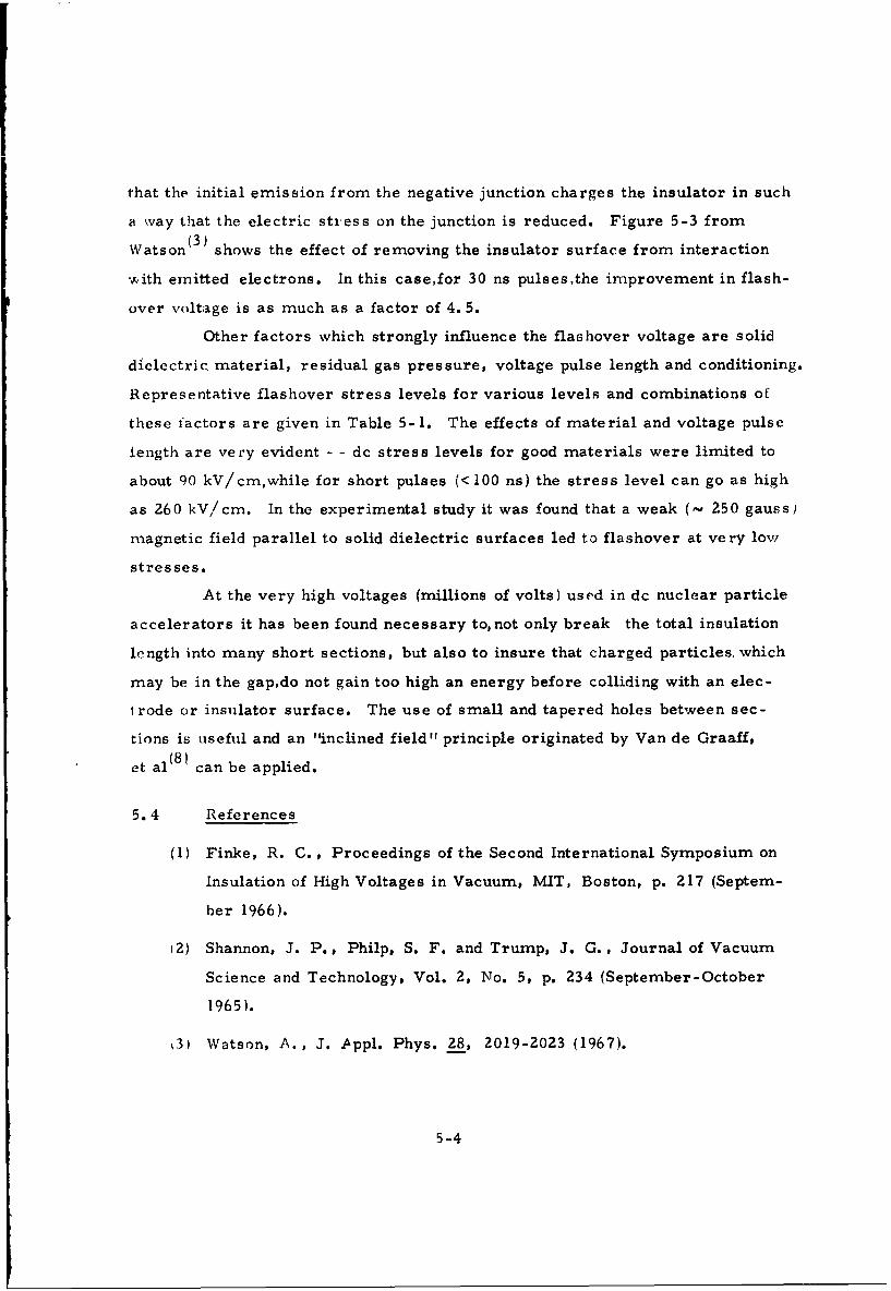
that the initial emission from the negative junction charges the insulator in such
a way that the electric stress on the junction is reduced. Figure 5-3 from
Watson(3) shows the effect of removing the insulator surface from interaction
• rith emitted electrons. In this case,for 30 ns pulses,the improvement in flash-
over voltage is as much as a factor of 4. 5.
Other factors which strongly influence the flashover voltage are solid
dielectric material, residual gas pressure, voltage pulse length and conditioning.
Representative flashover stress levels for various levels and combinations of
these factors are given in Table 5-1. The effects of material and voltage pulse
length are very evident - - dc stress levels for good materials were limited to
about 90 kV/cm,while for short pulses (< 100 ns) the stress level can go as high
as 260 kV/cm. In the experimental study it was found that a weak (- 250 gauss)
magnetic field parallel to solid dielectric surfaces led to flashover at very low
stresses.
At the very high voltages (millions of volts) used in dc nuclear particle
accelerators it has been found necessary to, not only break the total insulation
length into many short sections, but also to insure that charged particles, which
may be in the gap,do not gain too high an energy before colliding with an elec-
trode or insulator surface. The use of small and tapered holes between sec-
tions is useful and an "inclined field" principle originated by Van de Graaff,
et al 8) can be applied.
5.4 References
(1) Finke, R. C., Proceedings of the Second International Symposium on
Insulation of High Voltages in Vacuum, MIT, Boston, p. 217 (Septem-
ber 1966).
(2) Shannon, J. P., Philp, S. F. and Trump, J. G., Journal of Vacuum
Science and Technology, Vol. 2, No. 5, p. 234 (September-October
1965).
13) Watson, A., J. Appl. Phys. 28, 2019-2023 (1967).
5-4
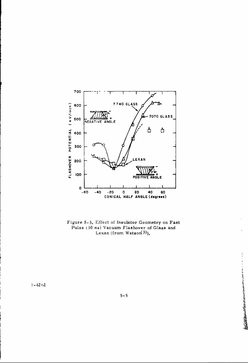
700 T
600 7740 GLASSU
> /f 7070 GLASS> 500
NEGATIVE ANGLE
<•400 -V
1" 3000.
~200 - LEXAN
10 000u.POSITIVE ANGLE
0 1 1 1
-60 -40 -20 0 20 40 60
CONICAL HALF ANGLE (degrees)
Figure 5-3. EIffect of Insulator Geometry on Fast
Pulse (30 ns) Vacuum Flashover of Glass and
Lexan (from Watson( 3 )).
I - 42 2
5-5
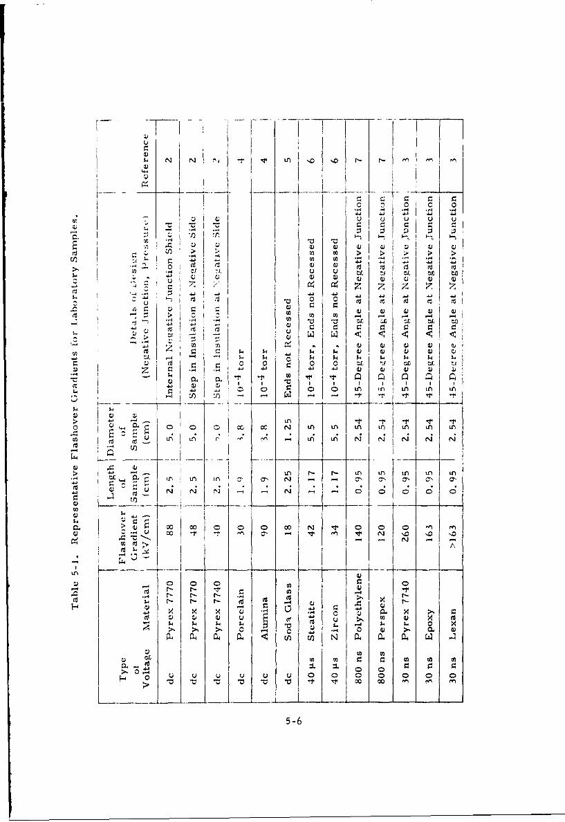
$4 N NI (N ~ ~ Lfl '0 '0 ' -n
- 0
lo >~ 0in 0) -4 -4~-
4j 4.' 4.
u J I' r. r. , r
-3r 0 .1 "
1-4.
cL~i -4-r- .
04 0 0o n i ni~f) n U
4 r
(U 0 C 0 r> in r-i i i n t
-4 L- in if) ol -7 N - Er) CH N Ncd N~ (IiC C,
> 0 000) 0 0
C) 0C) $
4.J -4 xal0 0 040 0"I 4 uU 0) '
-1 N a) ' '0 'I 4J - N -
-) r- r. 0 U) w M.0 W 4,
-4 >. 0 0 00e
L '. U
-4 $ $4 $4 4 $4 - $ $50-6
(4) Srivastava, K. D., Proceedings of the Eighth Electrical Insulation
Conference, 68C6-EI-28, p. 14-20, Los Angeles, California (Decem-
ber 1968).
(5) Gleichauf, P. H., Jr., J. Appl. Phys. 22, pp 535-541 and 766-771
(May-June 1951).
(6) Kofoid, M. J., Trans. AIEE, USA, Part III, 79, pp 991-1004 (1960).
(7) Smith, I. D., Proceedings of the First International Symposium on
Insulation of High Voltages in Vacuum, p. 261, MIT, Boston (October
1964).
(8) Van de Graaff, R. J., Rose, P. H., and Wittkower, A. B., Nature
195, 1292 (1962).
5-7