· pdf fileelements of communication switching system 1.5. ... satellite communication fig....
TRANSCRIPT
1.1. Introduction
1.2. Historical Development
1.3. Signal Characteristics
1.4. Elements of Communication Switching System
1.5. Criteria for the Design of Telecmmunication System
1.6. Fundamentals for the Design of Telecommunication Network
1.7. Centralized Switching System
1.8. AT & T and ITU—(or CCITT) Hierarchical Networks
1.9. Telecommunication Networks
Acronyms
Related Website
Chapter Review Questions
1����������������� ���������
2
������������������ ���������
1.1. INTRODUCTION
Telecommunication networks carry information signals among entities, which aregeographically far apart. An entity may be a computer or human being, a facsimile machine, ateleprinter, a data terminal and so on. The entities are involved in the process of informationtransfer which may be in the form of a telephone conversation (telephony) or a file transferbetween two computers or message transfer between two terminals etc. Today it is almosttruism to state that telecommunication systems are the symbol of our information age.
With the rapidly growing traffic and untargeted growth of cyberspace, telecommunicationbecomes a fabric of our life. The future challenges are enormous as we anticipate rapid growthitems of new services and number of users. What comes with the challenge is a genuine needfor more advanced methodology supporting analysis and design of telecommunicationarchitectures. Telecommunication has evaluated and growth at an explosive rate in recentyears and will undoubtedly continue to do so.
The communication switching system enables the universal connectivity. The universalconnectivity is realized when any entity in one part of the world can communicate with anyother entity in another part of the world. In many ways telecommunication will acts as asubstitute for the increasingly expensive physical transportation.
The telecommunication links and switching were mainly designed for voicecommunication. With the appropriate attachments/equipments, they can be used to transmitdata. A modern society, therefore needs new facilities including very high bandwidth switcheddata networks, and large communication satellites with small, cheap earth antennas.
1.2. HISTORICAL DEVELOPMENT
By the early 1800’s scientists had developed ways to generate and transmit electricity. In1819, oersted discovered the relation between magnetism and electricity. Ampere, Faradayand others continued this work in 1820. In 1834, Gauss and Weber wired over the roofs ofGottingen to make a telegraph system.
Samuel F.B. Morse’s developed the first significant work in telecommunication. F.B.Morse developed code telegraphy in 1837. In 1844, a 40 mile telegraph line was setup betweenBaltimore and Washington by F.B. Morse. In 1845, Morse formed a telegraph company basedon his technology. In 1849, the first slow telegraph printer link was setup. In 1874, Ban dot
Introduction to Switching Systems 3
dharmd:\N-Tele\Tel1-1.pm5
invented a ‘‘Multiplexes” system which enables up to six signal from telegraph machines to betransmitted together over the same line.
Elisha Gray and Alexander Graham Bell contributed significant works and filed paperrelated to telephony. The early stages of the development of telecommunication were due toA.G. Bell, G. Marconi and C.E. Shannon. In 1876, Bell invented a telephone system. In 1897Marconi patented a wireless telephone system. Teletypewriter service was initiated in 1931.
In early days, a very simple exchanges whose control is provided by a human operatorand the elements of the switch assemblies are plugs and sacks.With increase in demand ofservice, human operator exchange was replaced by the invention of range of electromechanicalswitching devices. Of all the electromechanical switching devices that become available overthe years, the step-by-step switching system invented by Almon B. Strowger in 1892 is stillquite popular. The next automatic electromechanical switching system was crossber switching.First patent for crossbar device was granted in 1915 to J.N. Reynolds of wester Electric, USA.In 1919, two Swedish Engineers, Betulander and Palmgren got patent for crossbar switch. In1938, AT & T laboratories in US introduced crossbar-switching system in the field.
The electromechanical switching systems have been replaced by computer controlledswitching systems referred to as stored program control (SPC). In SPC, switching is controlledby software program. The first computer controlled switch was introduced in 1960. Till 1965,computer controlled switching was used transistors and printed circuit technology. Since 1965switching are based on microprocessors.
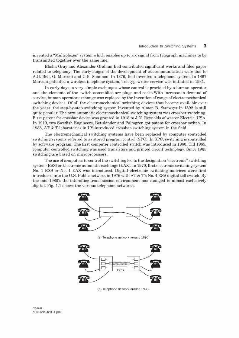
The use of computers to control the switching led to the designation ‘‘electronic’’ switchingsystem (ESS) or Electronic automatic exchange (EAX). In 1970, first electronic switching systemNo. 1 ESS or No. 1 EAX was introduced. Digital electronic switching matrices were firstintroduced into the U.S. Public network in 1976 with AT & T’s No. 4 ESS digital toll switch. Bythe mid 1980’s the interoffice transmission environment has changed to almost exclusivelydigital. Fig. 1.1 shows the various telephone networks.
(a) Telephone network around 1890
(b) Telephone network around 1988
CCS
4 Telecommunication Switching and Networks
dharmd:\N-Tele\Tel1-1.pm5
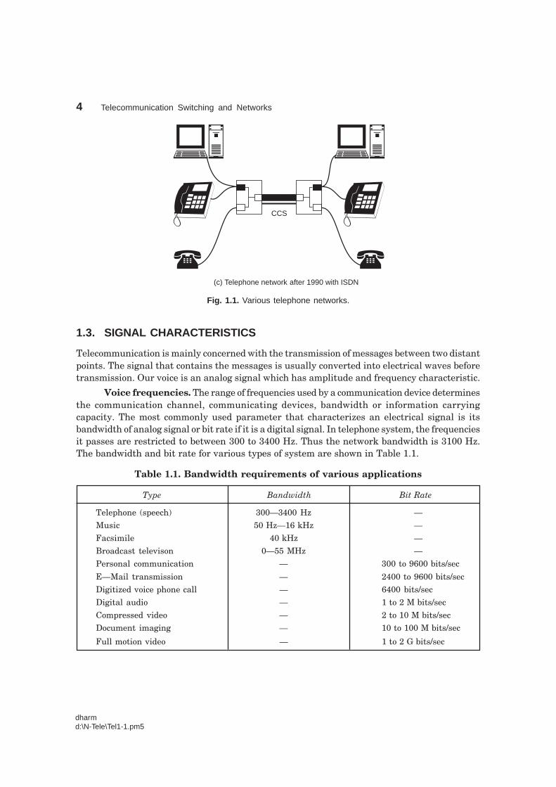
(c) Telephone network after 1990 with ISDN
CCS
Fig. 1.1. Various telephone networks.
1.3. SIGNAL CHARACTERISTICS
Telecommunication is mainly concerned with the transmission of messages between two distantpoints. The signal that contains the messages is usually converted into electrical waves beforetransmission. Our voice is an analog signal which has amplitude and frequency characteristic.
Voice frequencies. The range of frequencies used by a communication device determinesthe communication channel, communicating devices, bandwidth or information carryingcapacity. The most commonly used parameter that characterizes an electrical signal is itsbandwidth of analog signal or bit rate if it is a digital signal. In telephone system, the frequenciesit passes are restricted to between 300 to 3400 Hz. Thus the network bandwidth is 3100 Hz.The bandwidth and bit rate for various types of system are shown in Table 1.1.
Table 1.1. Bandwidth requirements of various applications
Type Bandwidth Bit Rate
Telephone (speech) 300—3400 Hz —
Music 50 Hz—16 kHz —
Facsimile 40 kHz —
Broadcast televison 0—55 MHz —
Personal communication — 300 to 9600 bits/sec
E—Mail transmission — 2400 to 9600 bits/sec
Digitized voice phone call — 6400 bits/sec
Digital audio — 1 to 2 M bits/sec
Compressed video — 2 to 10 M bits/sec
Document imaging — 10 to 100 M bits/sec
Full motion video — 1 to 2 G bits/sec
Introduction to Switching Systems 5
dharmd:\N-Tele\Tel1-1.pm5
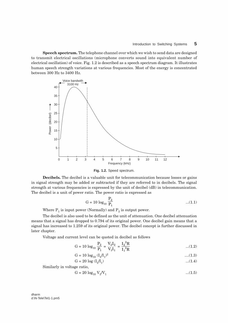
Speech spectrum. The telephone channel over which we wish to send data are designedto transmit electrical oscillations (microphone converts sound into equivalent number ofelectrical oscillation) of voice. Fig. 1.2 is described as a speech spectrum diagram. It illustrateshuman speech strength variations at various frequencies. Most of the energy is concentratedbetween 300 Hz to 3400 Hz.
0 1 2 3 4 5 6 7 8 9 10 11 12
5
10
15
20
25
30
35
40
Frequency (kHz)
Pow
er(d
ecib
el)
Voice bandwith3100 Hz
Fig. 1.2. Speed spectrum.
Decibels. The decibel is a valuable unit for telecommunication because losses or gainsin signal strength may be added or subtracted if they are referred to in decibels. The signalstrength at various frequencies is expressed by the unit of decibel (dB) in telecommunication.The decibel is a unit of power ratio. The power ratio is expressed as
G = 10 log10 PP
2
1...(1.1)
Where P1 is input power (Normally) and P2 is output power.
The decibel is also used to be defined as the unit of attenuation. One decibel attenuationmeans that a signal has dropped to 0.794 of its original power. One decibel gain means that asignal has increased to 1.259 of its original power. The decibel concept is further discussed inlater chapter.
Voltage and current level can be quoted in decibel as follows
G = 10 log10 PP
2
1 =
V IV I
2 2
1 1 =
I R
I R2
2
12 ...(1.2)
G = 10 log10 (I2/I1)2 ....(1.3)
G = 20 log (I2/I1) ...(1.4)Similarly in voltage ratio,
G = 20 log10 V2/V1 ...(1.5)
6 Telecommunication Switching and Networks
dharmd:\N-Tele\Tel1-1.pm5
Gain in nepers = loge II
2
1 = loge
VV
2
1...(1.6)
Relation : 1 N = 8.69 dB ...(1.7)
Example 1.1. If input power is 16 µW and output power is 30 mW, find the power ratioand express it in decibel and nepers.
Power = PP
2
1 =
30 1016 10
3
6
××
−
− = 1875 = 1.875 × 10³
Power in decibel, G = 10 log10 1.875 × 103 = 32.73 dB
Power in nepers, G = 3.76 N.
1.4. ELEMENTS OF COMMUNICATION SWITCHING SYSTEM
The purpose of a telecommunication switching system is to provide the means to passinformation from any terminal device to any other terminal device selected by the originator.Telecommunication system can be divided into four main parts. They are
1. End system or Instruments
2. Transmission system
3. Switching system
4. Signaling.
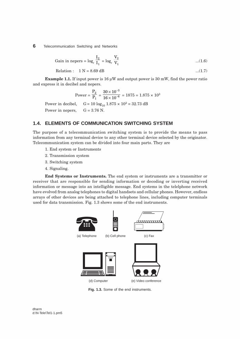
End Systems or Instruments. The end system or instruments are a transmitter orreceiver that are responsible for sending information or decoding or inverting receivedinformation or message into an intelligible message. End systems in the telelphone networkhave evolved from analog telephones to digital handsets and cellular phones. However, endlessarrays of other devices are being attached to telephone lines, including computer terminalsused for data transmission. Fig. 1.3 shows some of the end instruments.
(a) Telephone (b) Cell phone (c) Fax
(d) Computer (e) Video conference
Fig. 1.3. Some of the end instruments.
Introduction to Switching Systems 7
dharmd:\N-Tele\Tel1-1.pm5
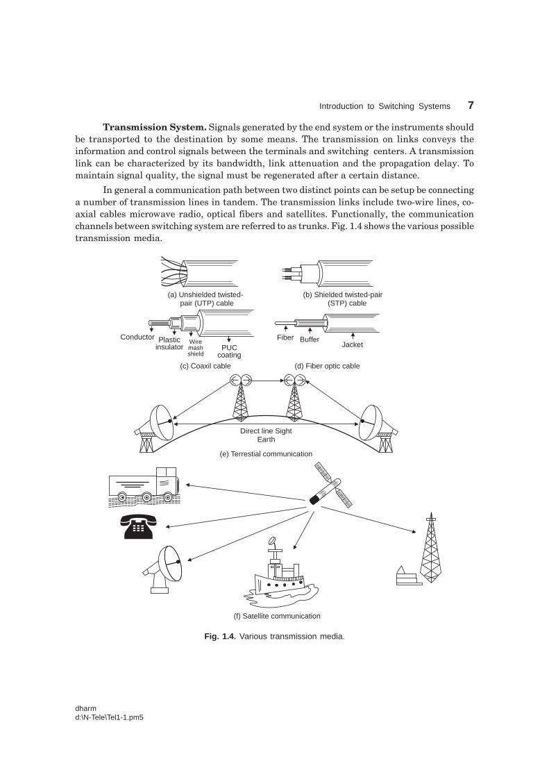
Transmission System. Signals generated by the end system or the instruments shouldbe transported to the destination by some means. The transmission on links conveys theinformation and control signals between the terminals and switching centers. A transmissionlink can be characterized by its bandwidth, link attenuation and the propagation delay. Tomaintain signal quality, the signal must be regenerated after a certain distance.
In general a communication path between two distinct points can be setup be connectinga number of transmission lines in tandem. The transmission links include two-wire lines, co-axial cables microwave radio, optical fibers and satellites. Functionally, the communicationchannels between switching system are referred to as trunks. Fig. 1.4 shows the various possibletransmission media.
(a) Unshielded twisted-pair (UTP) cable
(b) Shielded twisted-pair(STP) cable
(c) Coaxil cable
PUCcoating
Wiremashshield
Plasticinsulator
Conductor
(d) Fiber optic cable
Fiber BufferJacket
Direct line SightEarth
(e) Terrestial communication
(f) Satellite communication
Fig. 1.4. Various transmission media.
8 Telecommunication Switching and Networks
dharmd:\N-Tele\Tel1-1.pm5
Switching System. The switching centers receives the control signals, messages orconversations and forwards to the required destination, after necessary modification (linkamplifications) if necessary. A switching system is a collection of switching elements arrangedand controlled in such a way as to setup a communication path between any two distant points.A switching center of a telephone network comprising a switching network and its control andsupport equipment is called a central office.
In computer communication, the switching technique used is known as packet switchingor message switch (store and forward switching). In telephone network the switching methodused is called circuit switching. Some practical switching system are step-by-step, cross barredrelay system, digital swtiching systems, electronic switching system etc.
Signalling Systems. A signalling system in a data communication networks exchangessignalling information effectively between subscribers. The signalling systems are essentialbuilding blocks in providing the ultimate objective of a worldwide automatic telephone servicesstandardized. Signalling provides the interface between different national systems. Theintroduction of signalling system was the big step in improving the PSTN.
The consultative committe on international telegraphy and telephony (CCITT) based inGeneva, recommended seven formats related to signalling. The first five formats related to In-band signalling and the last two in the category of common channel signalling. In In-bandsignalling, voice information and signalling information travel on common paths, where as incommon channel signalling, they travel on separate paths. Further classification and detainedstudy are carried out in later chapter.
1.5. CRITERIA FOR THE DESIGN OF TELECOMMUNICATION SYSTEM
Traditionally, the design for telephone switching center or equipment requirement in atelecommunication system are determined on the basis of the traffic intensity of the busyhour. The traffic intersity is defined as the product of the calling rate and the average holdingtime. The busy hour is defined as that continuous sixty-minute period during which the trafficintersity is highest.
The calling rate is the average number of request for connection that are made per unittime. If the instant in time that a call request arises is a random variable, the calling rate maybe stated as the probability that a call request will occur in a certain short interval of time. Theholding time is the mean time that calls last. Otherwise the average holding time is the averageduration of occupancy of traffic path by a call.
Grade of Service. In telephone field, the so called busy hour traffic are used for planningpurposes. Once the statistical properties of the traffic are known, the objective for theperformance of a switching system should be stated. This is done by specifying a grade ofservice (GOS). GOS is a measure of congestion expressed as the probability that a call will beblocked or delayed. Thus when dealing with GOS in traffic engineering, the clear understandingof blocking criteria, delay criteria and congestion are essential.
Blocking criteria. If the design of a system is based on the fraction of calls blocked(the blocking probaility), then the system is said to be engineered on a blocking basis or callloss basis. Blocking can occur if all devices are occupied when a demand of service is initiated.
Introduction to Switching Systems 9
dharmd:\N-Tele\Tel1-1.pm5
Blocking criteria are often used for the dimensioning of switching networks and interofficetrunk groups. For a system designed on a loss basis, a suitable GOS is the percentage of callswhich are lost because no equipment is available at the instant of call request.
Delay criteria. If the design of a system is based on the fraction of calls delayed longerthan a specified length of time (the delay probability), the system is said to be a waiting systemor engineered on a delay basis. Delay criteria are used in telephone systems for the dimensioningof registers. In waiting system, a GOS objective could be either the percentage of calls whichare delayed or the percentage which are delayed more than a certain length of time.
Congestion. It is the condition in a switching center when a subscriber can not obtaina connection to the wanted subscriber immediately. In a circuit switching system, there will bea period of congestion during which no new calls can be accepted. There are two ways ofspecifying congestion.
1. Time congestion. It is the probability that all servers are busy. It is also called theprobability of blocking.
2. Call congestion. It is the proportion of calls arising that do not find a free server.Call congestion is a loss system and also known as the probability of loss while in a delaysystem it is referred to as the probability of waiting.
If the number of sources is equal to the number of servers, the time congestion is finite,but the call congestion is zero. When the number of sources is large in comparison with servers,the probability of a new call arising is independent of the number already in progress andtherefore the call congestion is equal to the time congestion. In general, time and call congestionsare different but in most practial cases, the discrepancies are small.
Measure of GOS. GOS is expressed as a probability. The GOS of 2% (0.02) mean that98% of the calls will reach a called instrument if it is free. Generally, GOS is quoted as P.02 orsimply P02 to represent a network busy probability of 0.02. GOS is applied to a terminal-to-terminal connection. For the system connection many switching centers, the system is generallybroken into following components.
(i) an internal call (calling subscriber to switching office)
(ii) an outgoing call to the trunk network (switching office to trunk)
(iii) The trunk network (trunk to trunk)
(iv) A terminating call (switching office to called subscriber)
The GOS of each component is called component GOS.
The GOS for internal calls is 3 to 5%, for trunk calls 1-3%, for outgoing calls 2% and forterminating calls 2%. The overall GOS of a system is approximately the sum of the componentgrade of service. In practice, in order to ensure that the GOS does not deteriorate disastrouslyif the actual busy hour traffic exceeds the mean, GOS are specified 10% or 20% more of themean.
1.6. FUNDAMENTALS FOR THE DESIGN OF TELECOMMUNICATIONNETWORK
A telephone network is composed of a variety of all processing equipments, interstate switchinglinks and inters office trunks. Because of the random nature of the call request, the design of
10 Telecommunication Switching and Networks
dharmd:\N-Tele\Tel1-1.pm5
equipments switching links and trunks are quite difficult. Thus, the traffic analysis is thefundamental request for the design of cost effective, efficient and effective configuration ofnetworks. The effectiveness of a network can be evaluated intermes of how much traffic itcarries under normal or average loads and how often the traffic volume exceeds the capacity ofthe network.
Fundamental problem in the design of telecommunication networks concerns thedimensioning of a route. To dimension the route, volume of traffic required grade of serviceand capacity (in bits per sec) must be known.
Traffic. In telecommunication system, traffic is defined as the occupancy of the serverin the network. There are two types of traffic viz. voice traffic and data traffic. For voice traffic,the calling rate is defined as the number of calls per traffic path during the busy hour. In a day,the 60 minutes interval in which the traffic is highest is called busy hour (BH).
Average occupancy. If the average number of calls to and from a terminal during aperiod T second is ‘n’ and the average holding time is ‘h’ seconds, the average occupancy of theterminal is given by
A = nhT
...(1.8)
The average occupancy is also referred as traffic flow of traffic intensity. The internationalunit of telephone traffic is the Erlang.
1.7. CENTRALIZED SWITCHING SYSTEM
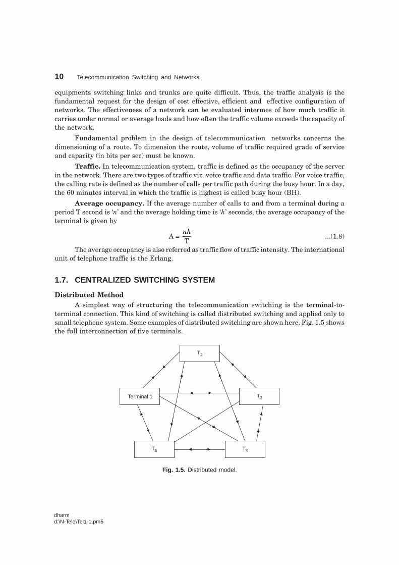
Distributed MethodA simplest way of structuring the telecommunication switching is the terminal-to-
terminal connection. This kind of switching is called distributed switching and applied only tosmall telephone system. Some examples of distributed switching are shown here. Fig. 1.5 showsthe full interconnection of five terminals.
T2
T3
T4T5
Terminal 1
Fig. 1.5. Distributed model.
Introduction to Switching Systems 11
dharmd:\N-Tele\Tel1-1.pm5
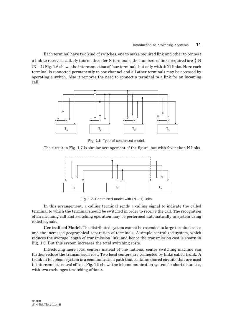
Each terminal have two kind of switches, one to make required link and other to connect
a link to receive a call. By this method, for N terminals, the numbers of links required are 12 N
(N – 1) Fig. 1.6 shows the interconnection of four terminals but only with 4(N) links. Here eachterminal is connected permanently to one channel and all other terminals may be accessed byoperating a switch. Also it removes the need to connect a terminal to a link for an incomingcall.
T4T3T2T1
Fig. 1.6. Type of centralised model.
The circuit in Fig. 1.7 is similar arrangement of the figure, but with fever than N links.
T1 T2 TN
Fig. 1.7. Centralised model with (N – 1) links.
In this arrangement, a calling terminal sends a calling signal to indicate the calledterminal to which the terminal should be switched in order to receive the call. The recognitionof an incoming call and switching operation may be performed automatically in system usingcoded signals.
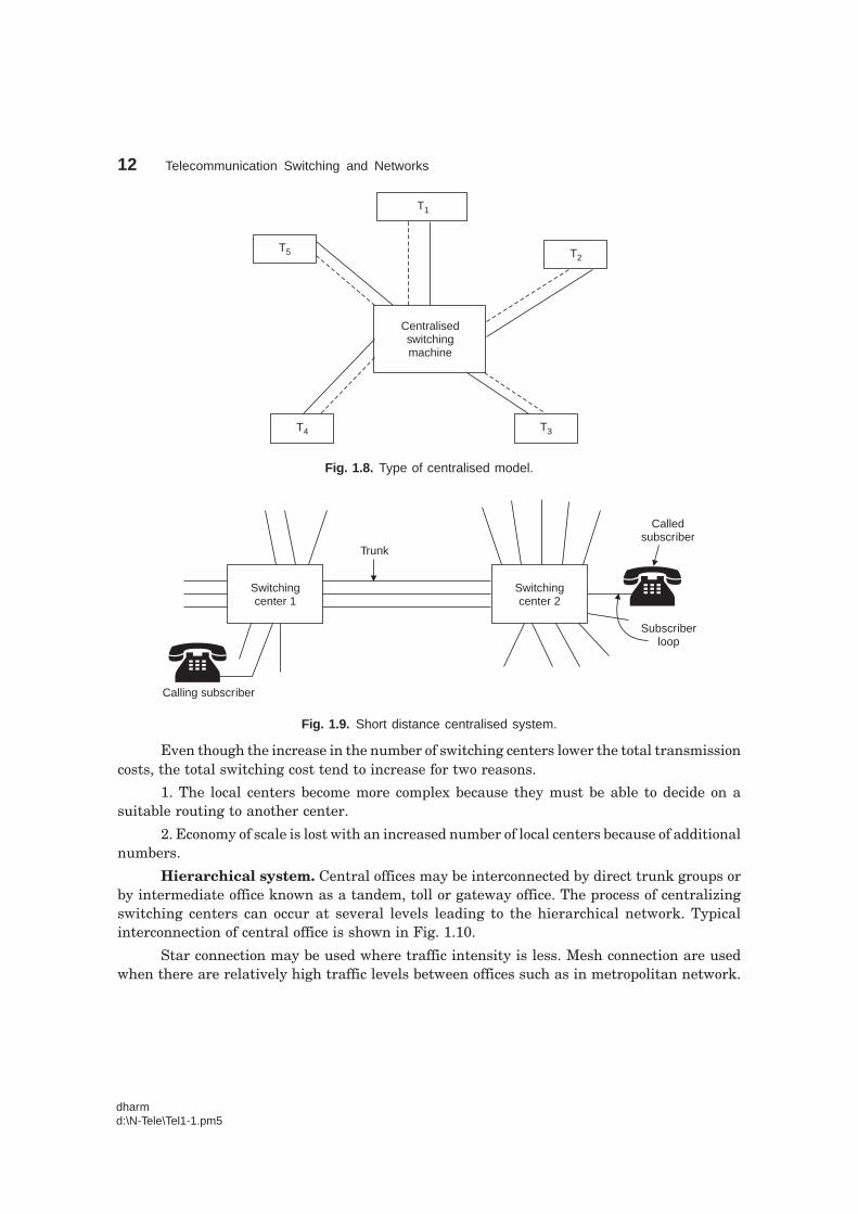
Centralised Model. The distributed system cannot be extended to large terminal casesand the increased geographical separation of terminals. A simple centralized system, whichreduces the average length of transmission link, and hence the transmission cost is shown inFig. 1.8. But this system increases the total switching costs.
Introducing more local centers instead of one national center switching machine canfurther reduce the transmission cost. Two local centers are connected by links called trunk. Atrunk in telephone system is a communication path that contains shared circuits that are usedto interconnect central offices. Fig. 1.9 shows the telecommunication system for short distances,with two exchanges (switching offices).
12 Telecommunication Switching and Networks
dharmd:\N-Tele\Tel1-1.pm5
Centralisedswitchingmachine
T1
T2
T3T4
T5
Fig. 1.8. Type of centralised model.
Switchingcenter 1
Switchingcenter 2
Trunk
Calledsubscriber
Subscriberloop
Calling subscriber
Fig. 1.9. Short distance centralised system.
Even though the increase in the number of switching centers lower the total transmissioncosts, the total switching cost tend to increase for two reasons.
1. The local centers become more complex because they must be able to decide on asuitable routing to another center.
2. Economy of scale is lost with an increased number of local centers because of additionalnumbers.
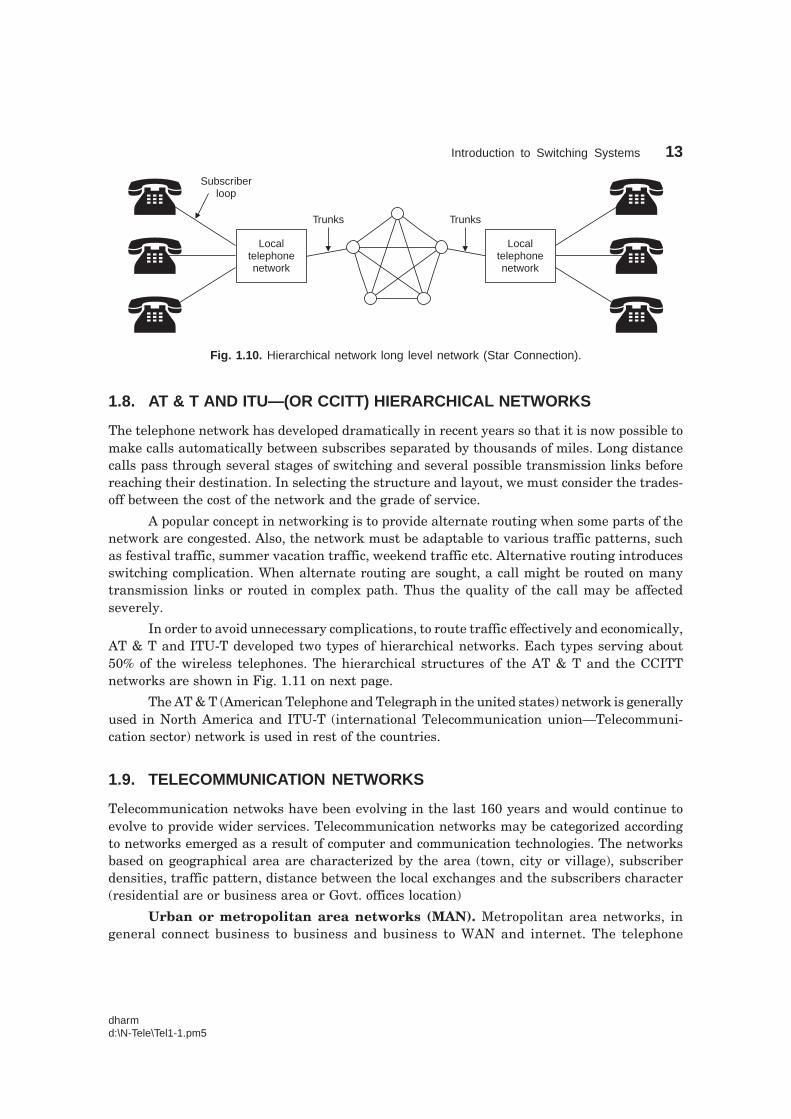
Hierarchical system. Central offices may be interconnected by direct trunk groups orby intermediate office known as a tandem, toll or gateway office. The process of centralizingswitching centers can occur at several levels leading to the hierarchical network. Typicalinterconnection of central office is shown in Fig. 1.10.
Star connection may be used where traffic intensity is less. Mesh connection are usedwhen there are relatively high traffic levels between offices such as in metropolitan network.
Introduction to Switching Systems 13
dharmd:\N-Tele\Tel1-1.pm5
Localtelephonenetwork
Localtelephonenetwork
Subscriberloop
Trunks Trunks
Fig. 1.10. Hierarchical network long level network (Star Connection).
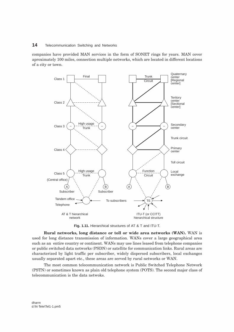
1.8. AT & T AND ITU—(OR CCITT) HIERARCHICAL NETWORKS
The telephone network has developed dramatically in recent years so that it is now possible tomake calls automatically between subscribes separated by thousands of miles. Long distancecalls pass through several stages of switching and several possible transmission links beforereaching their destination. In selecting the structure and layout, we must consider the trades-off between the cost of the network and the grade of service.
A popular concept in networking is to provide alternate routing when some parts of thenetwork are congested. Also, the network must be adaptable to various traffic patterns, suchas festival traffic, summer vacation traffic, weekend traffic etc. Alternative routing introducesswitching complication. When alternate routing are sought, a call might be routed on manytransmission links or routed in complex path. Thus the quality of the call may be affectedseverely.
In order to avoid unnecessary complications, to route traffic effectively and economically,AT & T and ITU-T developed two types of hierarchical networks. Each types serving about50% of the wireless telephones. The hierarchical structures of the AT & T and the CCITTnetworks are shown in Fig. 1.11 on next page.
The AT & T (American Telephone and Telegraph in the united states) network is generallyused in North America and ITU-T (international Telecommunication union—Telecommuni-cation sector) network is used in rest of the countries.
1.9. TELECOMMUNICATION NETWORKS
Telecommunication netwoks have been evolving in the last 160 years and would continue toevolve to provide wider services. Telecommunication networks may be categorized accordingto networks emerged as a result of computer and communication technologies. The networksbased on geographical area are characterized by the area (town, city or village), subscriberdensities, traffic pattern, distance between the local exchanges and the subscribers character(residential are or business area or Govt. offices location)
Urban or metropolitan area networks (MAN). Metropolitan area networks, ingeneral connect business to business and business to WAN and internet. The telephone
14 Telecommunication Switching and Networks
dharmd:\N-Tele\Tel1-1.pm5
companies have provided MAN services in the form of SONET rings for years. MAN coveraproximately 100 miles, connection multiple networks, which are located in different locationsof a city or town.
FinalClass 1
Class 2
Class 3
Class 4
Class 5
(Central office)
A B
High usageTrunk
Subscriber Subscriber
To subscribersTandem office
Telephone
AT & T hierarchicalnetwork
High usageTrunk
– – – –
A B
TE
ITU-T (or CCITT)hierarchical structure
FunctionCircuit
Localexchange
Toll circuit
Primarycenter
Trunk circuit
Secondarycenter
Teritorycenter[Sectionalcenter]
Quaternarycenter[Regionalcenter]
TrunkCircuit
Fig. 1.11. Hierarchical structures of AT & T and ITU-T.
Rural networks, long distance or toll or wide area networks (WAN). WAN isused for long distance transmission of information. WANs cover a large geographical areasuch as an entire country or continent. WANs may use lines leased from telephone companiesor public switched data networks (PSDN) or satellite for communication links. Rural areas arecharacterized by light traffic per subscriber, widely dispersed subscribers, local exchangesusually separated apart etc., these areas are served by rural networks or WAN.
The most common telecommunication network is Public Switched Telephone Network(PSTN) or sometimes known as plain old telephone system (POTS). The second major class oftelecommunication is the data netwoks.
Introduction to Switching Systems 15
dharmd:\N-Tele\Tel1-1.pm5
ARPNANET. In 1968, the United States Department of Defence (DOD) created theDefence Advanced Research Project Agency (DARPA) for research on packet switching networks.In 1969, DARPA created the Advanced Research Project Agency (ARPA). ARPA built anexperimental network (ARPANET). It is highly useful in interconnecting heterogeneoussystems.
TYMNET. It is an another large scale, general purpose data network introduced in1970, interconnecting geographically distributed computer systems, users and peripherals.
ISDN. Integrated Services Digital Network is now emerging as an major telecommuni-cation network. It is capable of carrying multimedia services like voice, data, video and facsimile.
Intelligent Network. It is the public telephone network that contains the logic forrouting calls, establishing connections and providing advanced features such as unique customerservices and customer programming of the network. This consists of a signalling path that isseparate from the central logic call circuit. Call setup information in handled by SS7 (signallingsystem 7), and the information transferred via packets across an overlay packet switchingnetwork.
New Public Network (NPN). It is the convergence of PSTN and the Internet. It allowsInternet phone users to connect with PSTN telephone users and vice versa. If provides thereliability and 99.999% of availability of the PSTN. Internet engineers have developed theirown set of protocols that provide telephony services over the Internet and interconnectionwith the PSTN.
ACRONYMS
ARPA — Advanced Research Project AgencyAT & T — American Telephone and TelegraphCCITT — Consultative Committee on International Telegraphy and TelephonyDARPA — Defense Advanced Research Project AgencyDOD — Department of DefenseEAX — Electronic Automatic ExchangeESS — Electronic Switching SystemGOS — Grade of ServiceIN — Intelligent NetworkISDN — Integrated Services Digital NetworkITU-T — International Telecommunication Union-Telecommunication sectorMAN — Metropolitan Area NetworkNPN — New Public NetworkPOTS — Plain Old Telephone systemsPSTN — Public Switched Telephone NetworkSPC — Stored Program ControlWAN — Wide Area Network
16 Telecommunication Switching and Networks
dharmd:\N-Tele\Tel1-1.pm5
RELATED WEBSITE
Fundamentals of Telecommunication —http://www.iec.org/tutorials/fund-telecom/
Good overview of telecommunication technologies
—http://www.Paradyne.com/sourcebook_offer/Sb_Pdf_Hom/
Good overview of telecommunication technologies —http://www.us-epanorama.net
Telecommunication magagine —http://www-telecoms.jnag.com/
Telephony world-com —http://www.telephonyworld-com/
REVIEW QUESTIONS
1. What is meant by telecommunication network ?
2. What is the range of voice frequencies ?
3. Define bandwidth.
4. Tabulate bandwidth and bit-rate of various applications.
5. Plot the speech spectrum.
6. Define decibel.
7. What are the elements of telecommunication systems ?
8. List the end systems of instruments of telecommunication systems.
9. List the various methods of transmission systems.
10. What are the various switching techniques in computer communication ?
11. What is meant by GOS ?
12. What is known as blocking criteria ?
13. What is meant by delay criteria ?
14. Define congestion.
15. Explain briefly the two types of congestion.
16. How the GOS can be expressed ?
17. What is meant by component GOS ?
18. Define traffic.
19. Define average occupancy.
20. Explain briefly with neat diagrams, the centralized switching and distributed switching.
21. Draw the typical hierarchical network structure and explain.
22. Compare with neat sketch, the AT and T and CCITT hierarchical structure and explain.
23. Define MAN and WAN.
24. Write short notes on (a) ISDN (b) IN and (c) NPN.