odu mini-snap pc - hvssystem.com pc.pdf · odu mini-snap pc miniature cylindrical connectors with...
TRANSCRIPT
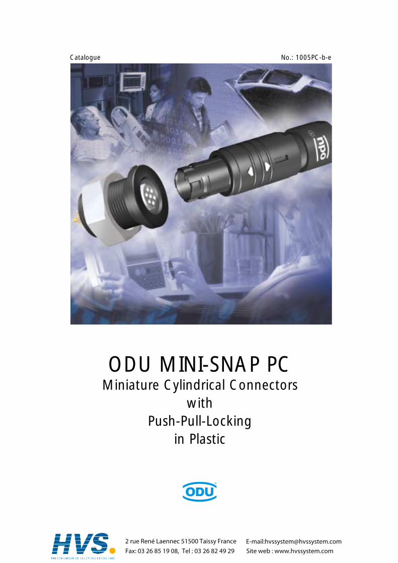
ODU MINI-SNAP PCMiniature Cylindrical Connectors
withPush-Pull-Locking
in Plastic
Catalogue No.: 1005PC-b-e
2 rue René Laennec 51500 Taissy FranceFax: 03 26 85 19 08, Tel : 03 26 82 49 29
E-mail:[email protected] web : www.hvssystem.com

All data and specifications subjectto change without notice.All dimensions in mm.All pictures are illustrations.
The latest version of this catalogueis posted on our websites:www.odu.de or www.odu-usa.com
UL-File E110586 01 RT07175
2 rue René Laennec 51500 Taissy FranceFax: 03 26 85 19 08, Tel : 03 26 82 49 29
E-mail:[email protected] web : www.hvssystem.com

Introduction . . . . . . . . . . . . . . . . . . . . . . . . . . . . . . . . . . . . . . . . . . . . . . . . . . . . . . . . . . . . . . . . . . . . . . . . . . . . . . . 5Product description . . . . . . . . . . . . . . . . . . . . . . . . . . . . . . . . . . . . . . . . . . . . . . . . . . . . . . . . . . . . . . . . . . . . . . . . . . . 6Applications . . . . . . . . . . . . . . . . . . . . . . . . . . . . . . . . . . . . . . . . . . . . . . . . . . . . . . . . . . . . . . . . . . . . . . . . . . . . . . . . 7
General Product Information. . . . . . . . . . . . . . . . . . . . . . . . . . . . . . . . . . . . . . . . . . . . . . . . . . . . . . . . . . . . . . . . . . 9Important Issues At A Glance . . . . . . . . . . . . . . . . . . . . . . . . . . . . . . . . . . . . . . . . . . . . . . . . . . . . . . . . . . . . . . . . . . 10Straight Plugs . . . . . . . . . . . . . . . . . . . . . . . . . . . . . . . . . . . . . . . . . . . . . . . . . . . . . . . . . . . . . . . . . . . . . . . . . . . . . . 11Receptacles . . . . . . . . . . . . . . . . . . . . . . . . . . . . . . . . . . . . . . . . . . . . . . . . . . . . . . . . . . . . . . . . . . . . . . . . . . . . . . . . 12In-Line Receptacles . . . . . . . . . . . . . . . . . . . . . . . . . . . . . . . . . . . . . . . . . . . . . . . . . . . . . . . . . . . . . . . . . . . . . . . . . . 13Stamped and formed contacts . . . . . . . . . . . . . . . . . . . . . . . . . . . . . . . . . . . . . . . . . . . . . . . . . . . . . . . . . . . . . . . . . 14Stamped and formed contacts - processing . . . . . . . . . . . . . . . . . . . . . . . . . . . . . . . . . . . . . . . . . . . . . . . . . . . . . . . . 15Turned contacts . . . . . . . . . . . . . . . . . . . . . . . . . . . . . . . . . . . . . . . . . . . . . . . . . . . . . . . . . . . . . . . . . . . . . . . . . . . . 17Compatibility . . . . . . . . . . . . . . . . . . . . . . . . . . . . . . . . . . . . . . . . . . . . . . . . . . . . . . . . . . . . . . . . . . . . . . . . . . . . . . 18Inserts . . . . . . . . . . . . . . . . . . . . . . . . . . . . . . . . . . . . . . . . . . . . . . . . . . . . . . . . . . . . . . . . . . . . . . . . . . . . . . . . . . . 18
Special designs for the ODU MINI-SNAP PC . . . . . . . . . . . . . . . . . . . . . . . . . . . . . . . . . . . . . . . . . . . . . . . . . . . . . 19Watertight connectors, IP 68 . . . . . . . . . . . . . . . . . . . . . . . . . . . . . . . . . . . . . . . . . . . . . . . . . . . . . . . . . . . . . . . . . . . 20Shielded version, > 60 dB . . . . . . . . . . . . . . . . . . . . . . . . . . . . . . . . . . . . . . . . . . . . . . . . . . . . . . . . . . . . . . . . . . . . . 21Receptacle „disposable” = One-Way-Version . . . . . . . . . . . . . . . . . . . . . . . . . . . . . . . . . . . . . . . . . . . . . . . . . . . . . . 22Autoclaving . . . . . . . . . . . . . . . . . . . . . . . . . . . . . . . . . . . . . . . . . . . . . . . . . . . . . . . . . . . . . . . . . . . . . . . . . . . . . . . 23
Part Number Key . . . . . . . . . . . . . . . . . . . . . . . . . . . . . . . . . . . . . . . . . . . . . . . . . . . . . . . . . . . . . . . . . . . . . . . . 25
Dimensions . . . . . . . . . . . . . . . . . . . . . . . . . . . . . . . . . . . . . . . . . . . . . . . . . . . . . . . . . . . . . . . . . . . . . . . . . . . . . . . 28Straight Plugs . . . . . . . . . . . . . . . . . . . . . . . . . . . . . . . . . . . . . . . . . . . . . . . . . . . . . . . . . . . . . . . . . . . . . . . . . . . . . . 28Receptacles . . . . . . . . . . . . . . . . . . . . . . . . . . . . . . . . . . . . . . . . . . . . . . . . . . . . . . . . . . . . . . . . . . . . . . . . . . . . . . . . 29In-Line Receptacles . . . . . . . . . . . . . . . . . . . . . . . . . . . . . . . . . . . . . . . . . . . . . . . . . . . . . . . . . . . . . . . . . . . . . . . . . . 30
Type Definition. . . . . . . . . . . . . . . . . . . . . . . . . . . . . . . . . . . . . . . . . . . . . . . . . . . . . . . . . . . . . . . . . . . . . . . . . . . . 31Straight plugs . . . . . . . . . . . . . . . . . . . . . . . . . . . . . . . . . . . . . . . . . . . . . . . . . . . . . . . . . . . . . . . . . . . . . . . . . . . . . . 32Receptacles . . . . . . . . . . . . . . . . . . . . . . . . . . . . . . . . . . . . . . . . . . . . . . . . . . . . . . . . . . . . . . . . . . . . . . . . . . . . . . . . 33In-Line Receptacles . . . . . . . . . . . . . . . . . . . . . . . . . . . . . . . . . . . . . . . . . . . . . . . . . . . . . . . . . . . . . . . . . . . . . . . . . . 34
Inserts and Contact Configurations . . . . . . . . . . . . . . . . . . . . . . . . . . . . . . . . . . . . . . . . . . . . . . . . . . . . . . . . . . . 35Size 1 . . . . . . . . . . . . . . . . . . . . . . . . . . . . . . . . . . . . . . . . . . . . . . . . . . . . . . . . . . . . . . . . . . . . . . . . . . . . . . . . . . . . 36Size 2 . . . . . . . . . . . . . . . . . . . . . . . . . . . . . . . . . . . . . . . . . . . . . . . . . . . . . . . . . . . . . . . . . . . . . . . . . . . . . . . . . . . . 38Size 3 . . . . . . . . . . . . . . . . . . . . . . . . . . . . . . . . . . . . . . . . . . . . . . . . . . . . . . . . . . . . . . . . . . . . . . . . . . . . . . . . . . . . 40
More details for the Part Number Key . . . . . . . . . . . . . . . . . . . . . . . . . . . . . . . . . . . . . . . . . . . . . . . . . . . . . . . . . 43Coding, Housing . . . . . . . . . . . . . . . . . . . . . . . . . . . . . . . . . . . . . . . . . . . . . . . . . . . . . . . . . . . . . . . . . . . . . . . . . . . 44Insulation body material . . . . . . . . . . . . . . . . . . . . . . . . . . . . . . . . . . . . . . . . . . . . . . . . . . . . . . . . . . . . . . . . . . . . . . 45Contact type, Contact diameter . . . . . . . . . . . . . . . . . . . . . . . . . . . . . . . . . . . . . . . . . . . . . . . . . . . . . . . . . . . . . . . . 46Contact - Termination Cross Section (AWG) . . . . . . . . . . . . . . . . . . . . . . . . . . . . . . . . . . . . . . . . . . . . . . . . . . . . . . . 47Collet systems . . . . . . . . . . . . . . . . . . . . . . . . . . . . . . . . . . . . . . . . . . . . . . . . . . . . . . . . . . . . . . . . . . . . . . . . . . . . . 49Right-Angled PCB-Version . . . . . . . . . . . . . . . . . . . . . . . . . . . . . . . . . . . . . . . . . . . . . . . . . . . . . . . . . . . . . . . . . . . . 51Bend Protection Sleeves . . . . . . . . . . . . . . . . . . . . . . . . . . . . . . . . . . . . . . . . . . . . . . . . . . . . . . . . . . . . . . . . . . . . . . 52
Technical Informations for the ODU MINI-SNAP PC . . . . . . . . . . . . . . . . . . . . . . . . . . . . . . . . . . . . . . . . . . . . . . 53Current Load - Contacts . . . . . . . . . . . . . . . . . . . . . . . . . . . . . . . . . . . . . . . . . . . . . . . . . . . . . . . . . . . . . . . . . . . . . . 54Housing materials, Insulation body materials PBT + PEEK . . . . . . . . . . . . . . . . . . . . . . . . . . . . . . . . . . . . . . . . . . . . . . 56Mating Force, Demating Force and Pull-Off-Force . . . . . . . . . . . . . . . . . . . . . . . . . . . . . . . . . . . . . . . . . . . . . . . . . . . 57Electromagnetic Compatibility (EMC). . . . . . . . . . . . . . . . . . . . . . . . . . . . . . . . . . . . . . . . . . . . . . . . . . . . . . . . . . . . . 58Autoclaving of MINI-SNAP PC . . . . . . . . . . . . . . . . . . . . . . . . . . . . . . . . . . . . . . . . . . . . . . . . . . . . . . . . . . . . . . . . . . 59
Accessories . . . . . . . . . . . . . . . . . . . . . . . . . . . . . . . . . . . . . . . . . . . . . . . . . . . . . . . . . . . . . . . . . . . . . . . . . . . . . . . 61
Toolings . . . . . . . . . . . . . . . . . . . . . . . . . . . . . . . . . . . . . . . . . . . . . . . . . . . . . . . . . . . . . . . . . . . . . . . . . . . . . . . . . 65
Table of Contents ODU MINI-SNAP PC
2 rue René Laennec 51500 Taissy FranceFax: 03 26 85 19 08, Tel : 03 26 82 49 29
E-mail:[email protected] web : www.hvssystem.com
Assembly Instructions . . . . . . . . . . . . . . . . . . . . . . . . . . . . . . . . . . . . . . . . . . . . . . . . . . . . . . . . . . . . . . . . . . . . . . 73
General Technical Informations . . . . . . . . . . . . . . . . . . . . . . . . . . . . . . . . . . . . . . . . . . . . . . . . . . . . . . . . . . . . . . 79International Protection (IP) Classes (DIN EN 60 529) . . . . . . . . . . . . . . . . . . . . . . . . . . . . . . . . . . . . . . . . . . . . . . . 80Insulation Groups / Nominal Voltage / Test Voltage . . . . . . . . . . . . . . . . . . . . . . . . . . . . . . . . . . . . . . . . . . . . . . . . . 81Termination Styles . . . . . . . . . . . . . . . . . . . . . . . . . . . . . . . . . . . . . . . . . . . . . . . . . . . . . . . . . . . . . . . . . . . . . . . . . . . 83Conversion Table AWG to Metric . . . . . . . . . . . . . . . . . . . . . . . . . . . . . . . . . . . . . . . . . . . . . . . . . . . . . . . . . . . . . . . 85Quality Management. . . . . . . . . . . . . . . . . . . . . . . . . . . . . . . . . . . . . . . . . . . . . . . . . . . . . . . . . . . . . . . . . . . . . . . . . 86Technical Terms & Definitions . . . . . . . . . . . . . . . . . . . . . . . . . . . . . . . . . . . . . . . . . . . . . . . . . . . . . . . . . . . . . . . . . . 87
Inquiry Form (Fax) . . . . . . . . . . . . . . . . . . . . . . . . . . . . . . . . . . . . . . . . . . . . . . . . . . . . . . . . . . . . . . . . . . . . . . . . . 91
Part Number Key for Open Out . . . . . . . . . . . . . . . . . . . . . . . . . . . . . . . . . . . . . . . . . . . . . . . . . . . . . . . . . . 92
ODU MINI-SNAP PC Table of Contents
2 rue René Laennec 51500 Taissy FranceFax: 03 26 85 19 08, Tel : 03 26 82 49 29
E-mail:[email protected] web : www.hvssystem.com

Introduction

ODU MINI-SNAP PC Product Description
ODU MINI-SNAP PC: The Connector with Push-Pull-Locking in Plastic
Cylindrical Connectors are generally available with several locking mechanisms:
The most frequently used are: Threaded-Locking Sleeve Bayonet-Locking Push-Pull-Locking
Push-Pull-Connectors have a very simple locking mechanism:
The Advantages of Push-Pull-Connectors:
Quick and easy mating and demating Easy blind mating in difficult to-reach places Less panel space required Definite and secure locking condition Less mating required
Pulling on the cable or on the back nut causesthe locking fingers to grip tighter into the grooveinside receptacle. A separation is virtuallyimpossible.
Pulling on the outer plug housing disengages the locking fingers from the receptacle groove andthe connector separates easily.

Medical
Product Description ODU MINI-SNAP PC
Applications
Test and Measurement
Industrial ElectronicCommercial Electronic
Consumer Products

ODU MINI-SNAP PC For your notes
Gen
eral
Pro
du
ct
Info
rmat
ion
GeneralProduct Information

ODU MINI-SNAP PC General Product Informations
Important Issues At A Glance:
The series is certificated for and VDE.
Connector with plastic housing available in 3 sizes
Outside diameter between 12,5 mm and 19 mmNumber of contact positions: 2 to 27 position
With solder-, crimp and print termination available
Operation temperature: - 40 °C - + 120 °C
Compatible to ODU MINI-SNAP Series F & W.W. Fischer™(Must be checked)
5000 Mating Cycles with all contact types
High Economy:- Automatic crimping- Easy mounting of the contacts- Easy mounting from the connector- Economic solutions
Further Advantages:- 100 % touch protection- Low weight- Low mating forces- Non magnetic- Autoclavable, chemical resistant
Special designs- Watertight version, IP 68- Shielded version- Disposable = One-Way-Version- Autoclavable version
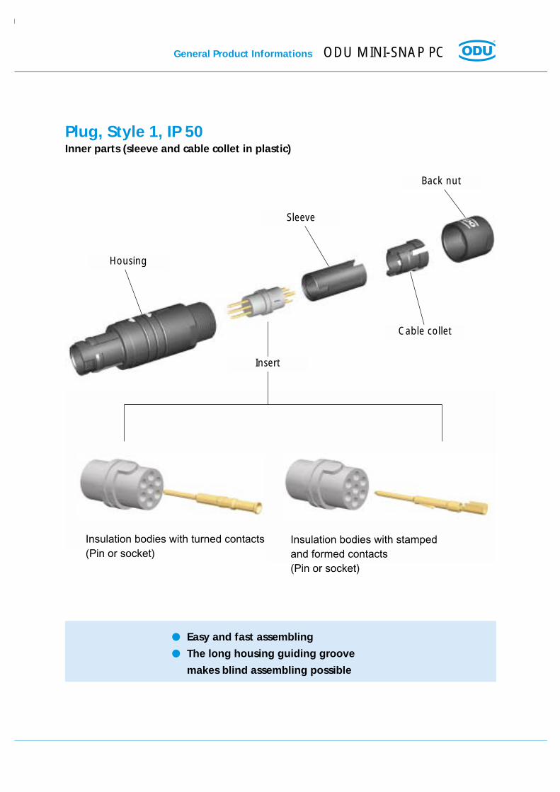
Insulation bodies with turned contacts(Pin or socket)
Insulation bodies with stampedand formed contacts(Pin or socket)
Plug, Style 1, IP 50Inner parts (sleeve and cable collet in plastic)
General Product Informations ODU MINI-SNAP PC
Easy and fast assembling
The long housing guiding groove
makes blind assembling possible
Insert
Housing
Sleeve
Back nut
Cable collet

ODU MINI-SNAP PC General Product Informations
Insulation bodies with turned contacts(Pin or socket)
Insulation bodies with stampedand formed contacts(Pin or socket)
Receptacle, Style 1, IP 50
Other styles see page 29
Insert
Hex Nut(Metal or Plastic)
Press ring(Metal)
Housing
Already mounted

Cable collet
Press ring Housing
HousingAlready mounted
Insulation bodies with turned contacts(Pin or socket)
Insulation bodies with stampedand formed contacts(Pin or socket)
General Product Informations ODU MINI-SNAP PC
In-Line Receptacle, Style 1, IP 50Inner part (cable collet) in plastic
Easy and fast assembling
Insert
Back nut
ODU MINI-SNAP PC General Product Informations
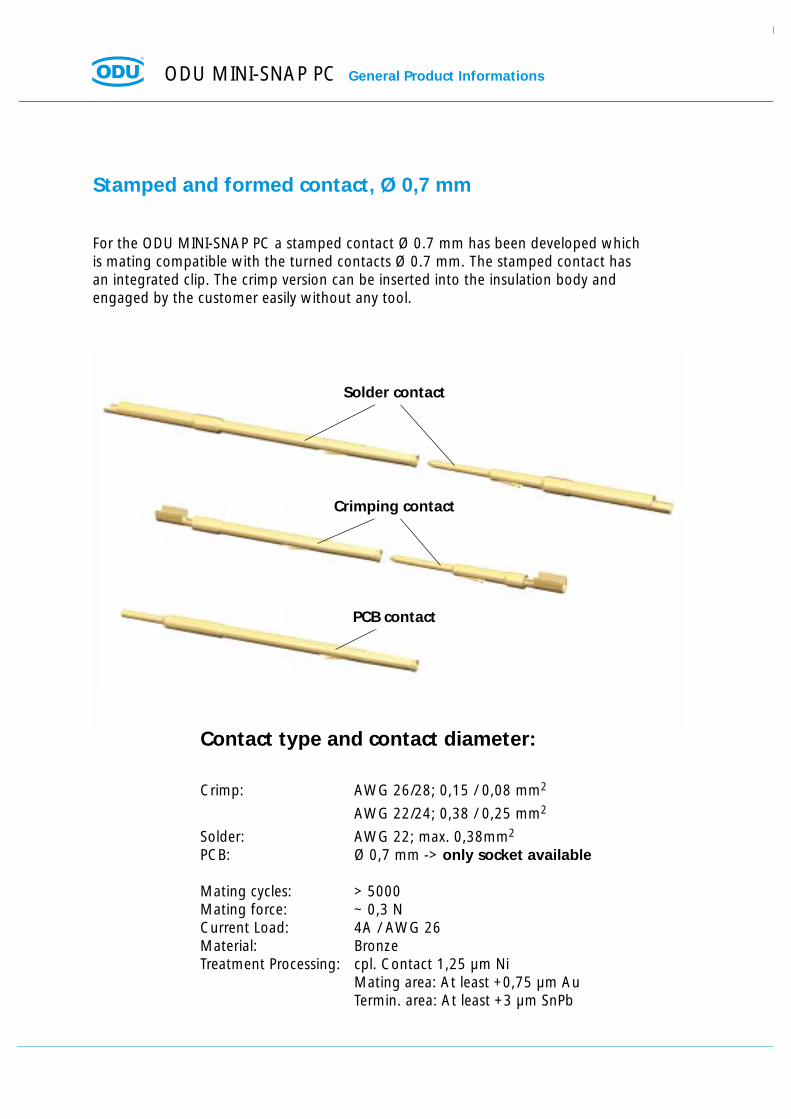
Stamped and formed contact, Ø 0,7 mm
For the ODU MINI-SNAP PC a stamped contact Ø 0.7 mm has been developed whichis mating compatible with the turned contacts Ø 0.7 mm. The stamped contact hasan integrated clip. The crimp version can be inserted into the insulation body andengaged by the customer easily without any tool.
Contact type and contact diameter:
Crimp: AWG 26/28; 0,15 / 0,08 mm2
AWG 22/24; 0,38 / 0,25 mm2
Solder: AWG 22; max. 0,38mm2
PCB: Ø 0,7 mm -> only socket available
Mating cycles: > 5000Mating force: ~ 0,3 NCurrent Load: 4A / AWG 26Material: BronzeTreatment Processing: cpl. Contact 1,25 µm Ni
Mating area: At least +0,75 µm AuTermin. area: At least +3 µm SnPb
Solder contact
Crimping contact
PCB contact

General Product Informations ODU MINI-SNAP PC
Stamped and formed contacts - processing
For stamped contacts with crimp termination there are new options:
Automatic crimping machines can be usedon cables which have been stripped toa very short length. Consequently they areideally suited for the ODU MINI-SNAP PC.
To order by:Fa. SchäferWerkzeug- und Sondermaschinen GmbHDr.-Alfred-Weckesser-Strasse 6D-76669 Bad Schönborn-La.Phone. 0 72 53 / 94 21-0Fax: 0 72 53 / 94 21-94Internet: www.schaefer-werkzeugbau.comeMail: [email protected]
The hand crimping tool feeds the contacton a tape and the contacts are separatedautomatically during the crimping process.Contacts are moved forward by hand ope-ration.
Hand Crimp Tool for Single-contact-processing (see next page)
Hand Crimp Tool with reel(080.000.041.000.000)
Stripper-Crimper forautomatic crimping

ODU MINI-SNAP PC General Product Informations
Stamped and formed contacts - processing
For stamped contacts with crimp termination there are new options:
Here Single Contacts are inserted intothe tong manually and are crimped.
Hand Crimp Tool forsingle contacts(080.000.040.000.000)

General Product Informations ODU MINI-SNAP PC
Turned contact
Turned contacts are available from the metal version ODU MINI-SNAP in the diametersof 0.5 to 2.0 mm.
The contacts are available with following terminations:
Solder
Crimp
PCB
Mating cycles: > 5000Material: BrassPlating: At least 1,25 µm Ni; at least 0,75 µm Au
Informations for diameter, termination styles and current loadplease find by the inserts (Page 36)
Print termination
Standard Pin
Solder termination
Crimp termination
ODU MINI-SNAP PC General Product Informations
Compatibility
ODU MINI-SNAP PC is intermatable with the metal version Series F. A part from this, whenchoosing the right inserts, the connector is intermatable with products of W.W. Fischer TM
(must be checked).
Inserts
ODU MINI-SNAP PC has been developed on the basis of the metal version ODU MINI-SNAP.Accordingly a lot of inserts of the series F and series B from the metal version in sizes1, 2, and 3 can be inserted into the MINI-SNAP PC.Approx. 100 different contact configurations are available right now.

Spec
ial d
esig
ns
Special designs
ODU MINI-SNAP PC Special designs
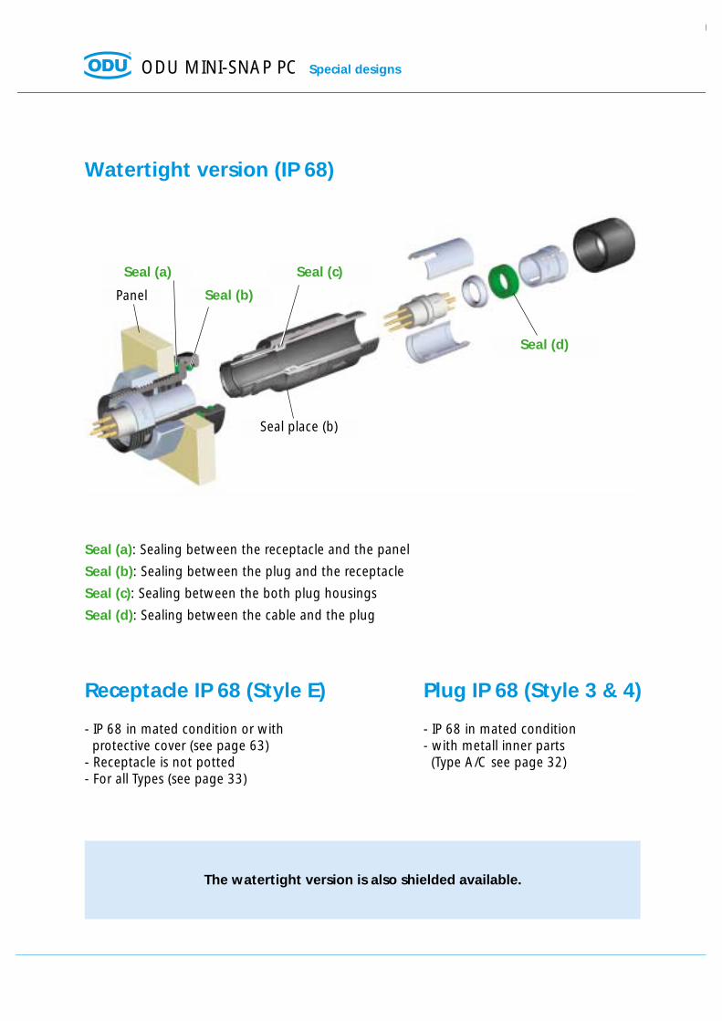
Watertight version (IP 68)
The watertight version is also shielded available.
Panel
Seal place (b)
Seal (b)
Seal (c)
Seal (d)
Seal (a)
Seal (a): Sealing between the receptacle and the panel
Seal (b): Sealing between the plug and the receptacle
Seal (c): Sealing between the both plug housings
Seal (d): Sealing between the cable and the plug
Receptacle IP 68 (Style E)
- IP 68 in mated condition or withprotective cover (see page 63)
- Receptacle is not potted- For all Types (see page 33)
Plug IP 68 (Style 3 & 4)
- IP 68 in mated condition- with metall inner parts
(Type A/C see page 32)
Special designs ODU MINI-SNAP PC
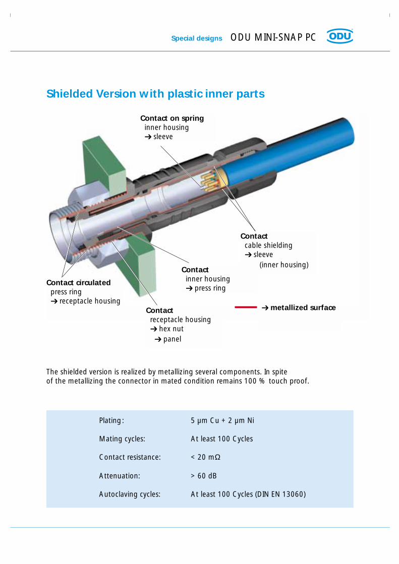
metallized surface
Contact circulatedpress ring receptacle housing
Contactreceptacle housing hex nut
panel
Contactinner housing press ring
Contactcable shielding sleeve
(inner housing)
Contact on springinner housing sleeve
Shielded Version with plastic inner parts
The shielded version is realized by metallizing several components. In spite of the metallizing the connector in mated condition remains 100 % touch proof.
Plating: 5 µm Cu + 2 µm Ni
Mating cycles: At least 100 Cycles
Contact resistance: < 20 mΩ
Attenuation: > 60 dB
Autoclaving cycles: At least 100 Cycles (DIN EN 13060)

ODU MINI-SNAP PC Special designs
Disposable / One-Way-Version
Custom specific connector (on request)
Not in shielded version available
Only with socket insert available
Hex nut plastic
Insert Turned or stamped and formed contacts
only socket version
Housing plastic
Already mounted
Special designs ODU MINI-SNAP PC
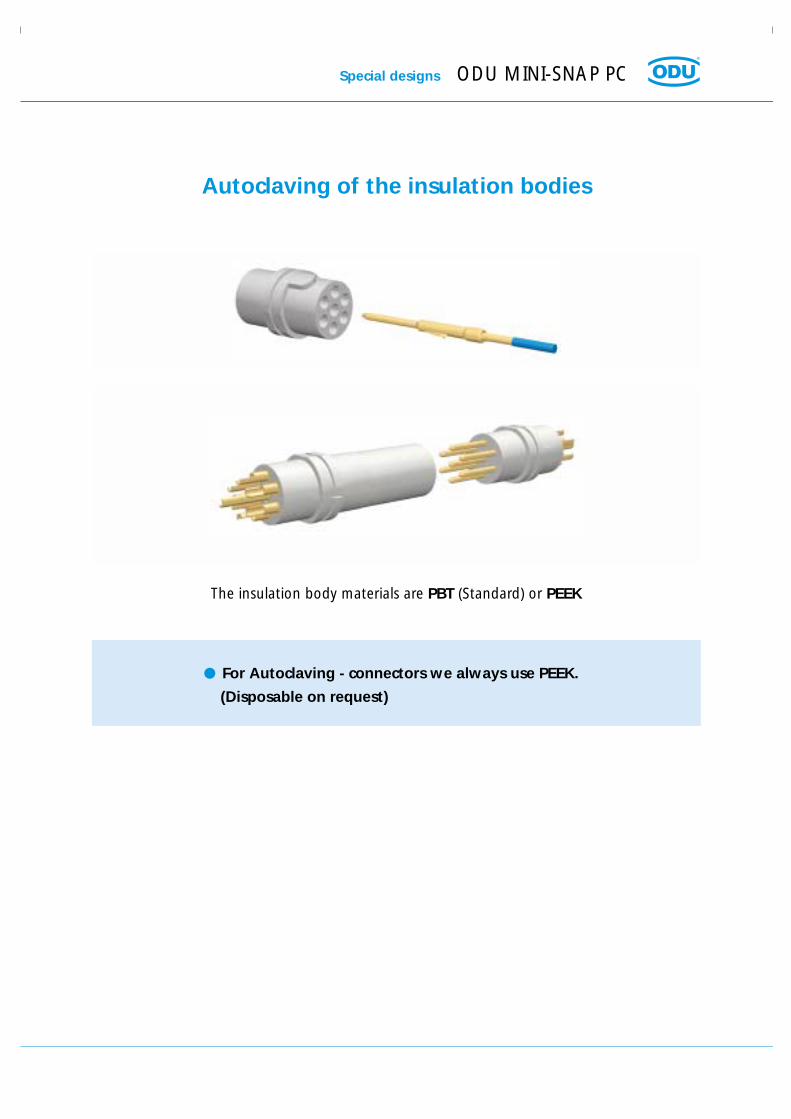
Autoclaving of the insulation bodies
For Autoclaving - connectors we always use PEEK.
(Disposable on request)
The insulation body materials are PBT (Standard) or PEEK

ODU MINI-SNAP PC For your notes
Part
Nu
mb
er K
ey, D
imen
sio
ns
and
Co
nta
ct C
on
fig
ura
tio
ns
Part Number KeyDimensions and
Contact Configurations

ODU MINI-SNAP PC For your notes

Example:
Plug – IP 68 – Size 1 – Type A – Coding 1 – Black plastic housing – PBT insulator – 7-way stamped and formed Crimp-Pin– AWG 28-26 – Cable diam. 4,1-4,5 mm – Black Cable Bend Relief - Material PUR
* If in field number 6 there is a 3 or 8, and in field number 4 there is a A, B, C, or D, it can be seen right away thatthis product is a Push-Pull Connector of the plastic PC version.
ODU Steckverbindungssysteme GmbH & Co. KG, Pregelstr. 11, D-84453 Mühldorf/Inn, Tel. +49/86 31/61 56-0, Fax +49/86 31/61 56 49, www.odu.de Page 27
Part Number Key ODU MINI-SNAP PC 1 2 3 4 5 6 7 8 9 10 11 12 13 14 15 16 17 18 19*
1. Connector S = plug
type G = receptacle
K = In-Line receptacle
2. Style 1 - 9 and A - Z
3. Size 1, 2 and 3
4. Type A, B, C and D (Page 31 - 34)
5. Coding (Page 44)
6. Material - Housing (Page 44)
8. Material - Insulator (Page 45)
9. + 10. Contact insert (Page 35 - 41)
z.B. 27-way = 27
11. Contact Type / Surface (Page 46)
12. Contact Diameter (Page 46)
13. + 14. Term. Cross Section
14. Special inserts 9
16. + 17. Collet System
18. + 19. Cable bend relief Color/Material (Page 52)
(Page 28 - 30)
(Page 28 - 30)
(Page 35 - 41)
(Page 47 - 48)
(Page 49 - 50)
1 2 3 4 5 6 7 8 9 10 11 12 13 14 15 16 17 18 19
S 4 1 A 1 8 T 0 7 4 F Z 0 4 5 G P

ODU MINI-SNAP PC Dimensions
1 2 3 4 5 6 7 8 9 10 11 12 13 14 15 16 17 18 19
Part Number Key
S - IP 50 – With Standard Back Nut
S 2
1
S 1S 3
S 2S 4
- IP 50 – With Back Nut for Cable Bend Relief
S 3 - IP 68 – Watertight with Standard Back Nut
S 4 - IP 68 – Watertight with Back Nut for Cable Bend Relief
Straight Plug (Suitable for all following receptacles and In-Line-Receptacles)
D
SW-A
L1
L2SW-B
Contact configuration from page 36
D
SW-A
L1
L2SW-B
Dimensions in mm
Size L1 L2 D SW-A SW-B
1 ~ 46 ~ 35 12,5 11 112 ~ 52 ~ 39 15 13 133 ~ 59 ~ 45 19 16 17
ODU Steckverbindungssysteme GmbH & Co. KG, Pregelstr. 11, D-84453 Mühldorf/Inn, Tel. +49/86 31/61 56-0, Fax +49/86 31/61 56 49, www.odu.de Page 29
Dimensions ODU MINI-SNAP PC 1 2 3 4 5 6 7 8 9 10 11 12 13 14 15 16 17 18 19
Part Number Key
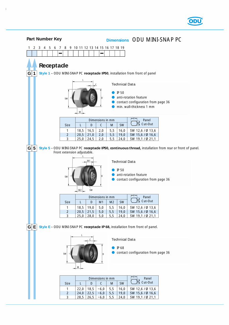
G Style 1 – ODU MINI-SNAP PC receptacle IP50, installation from front of panel1
Dimensions in mm Panel
Size L D C M SW Cut-Out
1 18,5 16,5 2,0 5,5 16,0 SW 12,6 / Ø 13,62 20,5 21,0 2,0 5,5 19,0 SW 15,6 / Ø 16,63 25,0 24,5 2,0 5,5 24,0 SW 19,1 / Ø 21,1
SW
Ø
Dimensions in mm Panel
Size L D M1 M2 SW Cut-Out
1 18,5 19,0 5,0 5,5 16,0 SW 12,6 / Ø 13,62 20,5 21,5 5,0 5,5 19,0 SW 15,6 / Ø 16,63 25,0 28,0 5,0 5,5 24,0 SW 19,1 / Ø 21,1
SW
Ø
Dimensions in mm Panel
Size L D C M SW Cut-Out
1 22,0 18,5 ~6,0 5,5 16,0 SW 12,6 / Ø 13,62 24,0 22,5 ~6,0 5,5 19,0 SW 15,6 / Ø 16,63 28,5 26,5 ~6,0 5,5 24,0 SW 19,1 / Ø 21,1
SW
Ø
Technical Data
IP 50 anti-rotation feature contact configuration from page 36 min. wall-thickness 1 mm
D
M
SW
C
L
G Style 5 – ODU MINI-SNAP PC receptacle IP50, continuous thread, installation from rear or front of panel.Front extension adjustable.
5
Technical Data
IP 50 anti-rotation feature contact configuration from page 36
D
M2
SW
SW
M1
L
G Style E – ODU MINI-SNAP PC receptacle IP 68, installation from front of panel.E
Technical Data
IP 68 contact configuration from page 36D
M
SW
C
L
Receptacle
ODU MINI-SNAP PC Dimensions
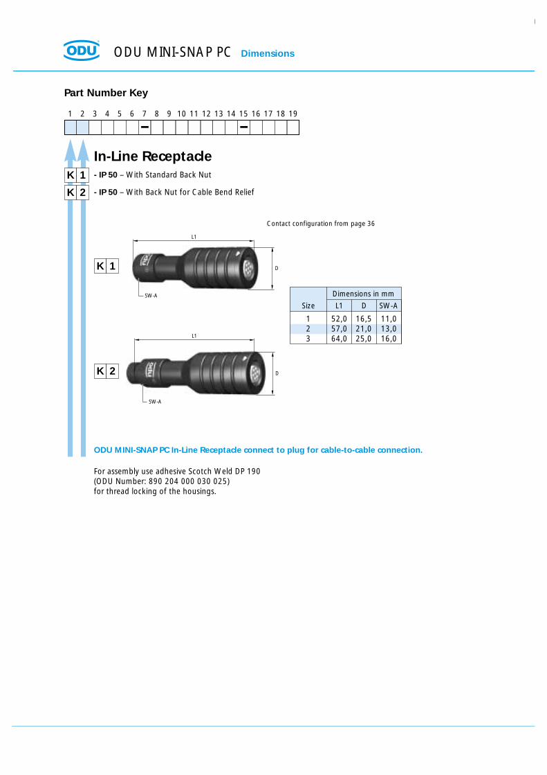
1 52,0 16,5 11,02 57,0 21,0 13,03 64,0 25,0 16,0
1 2 3 4 5 6 7 8 9 10 11 12 13 14 15 16 17 18 19
Part Number Key
K - IP 50 – With Standard Back Nut
K 2
1
K 1
K 2
- IP 50 – With Back Nut for Cable Bend Relief
In-Line Receptacle
D
SW-A
L1
D
SW-A
L1
Contact configuration from page 36
Dimensions in mm
Size L1 D SW-A
ODU MINI-SNAP PC In-Line Receptacle connect to plug for cable-to-cable connection.
For assembly use adhesive Scotch Weld DP 190(ODU Number: 890 204 000 030 025)for thread locking of the housings.

Type define
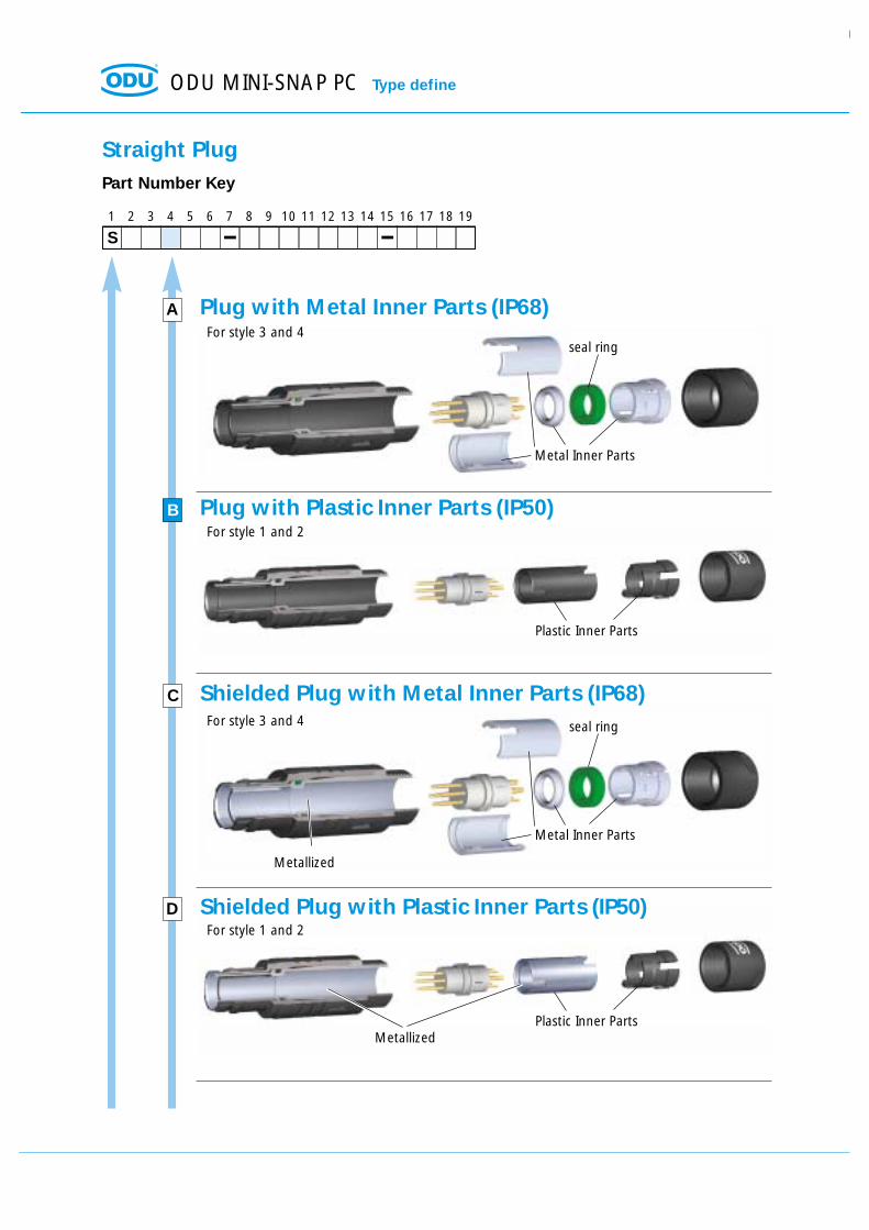
ODU MINI-SNAP PC Type define
1 2 3 4 5 6 7 8 9 10 11 12 13 14 15 16 17 18 19
Part Number Key
A
S
C
D
Straight Plug
Plug with Metal Inner Parts (IP68)
Plug with Plastic Inner Parts (IP50)
Shielded Plug with Metal Inner Parts (IP68)
Shielded Plug with Plastic Inner Parts (IP50)
Metal Inner Parts
seal ring
Metal Inner Parts
Metallized
Metallized
seal ring
Plastic Inner Parts
Plastic Inner Parts
For style 3 and 4
For style 1 and 2
For style 3 and 4
For style 1 and 2
B

ODU Steckverbindungssysteme GmbH & Co. KG, Pregelstr. 11, D-84453 Mühldorf/Inn, Tel. +49/86 31/61 56-0, Fax +49/86 31/61 56 49, www.odu.de Page 33
Type define ODU MINI-SNAP PC
1 2 3 4 5 6 7 8 9 10 11 12 13 14 15 16 17 18 19
Part Number Key
A
G
C
Receptacle
Receptacle with Metal Inner Part (press ring)
Shielded receptacle with Metal Inner Part (press ring)
Metal press ring
Already mounted
Already mountedMetal press ring
Metallized
For all styles (IP50 and IP 68)
For all styles (IP50 and IP 68)- Custom specific connector (on request)- Not in shielded version available
B Receptacle DisposableAll non conductive parts are made out of plastic
For style 1 and E. (Style 5 on request)
Notice: Receptacles are complete assembled
Already mounted
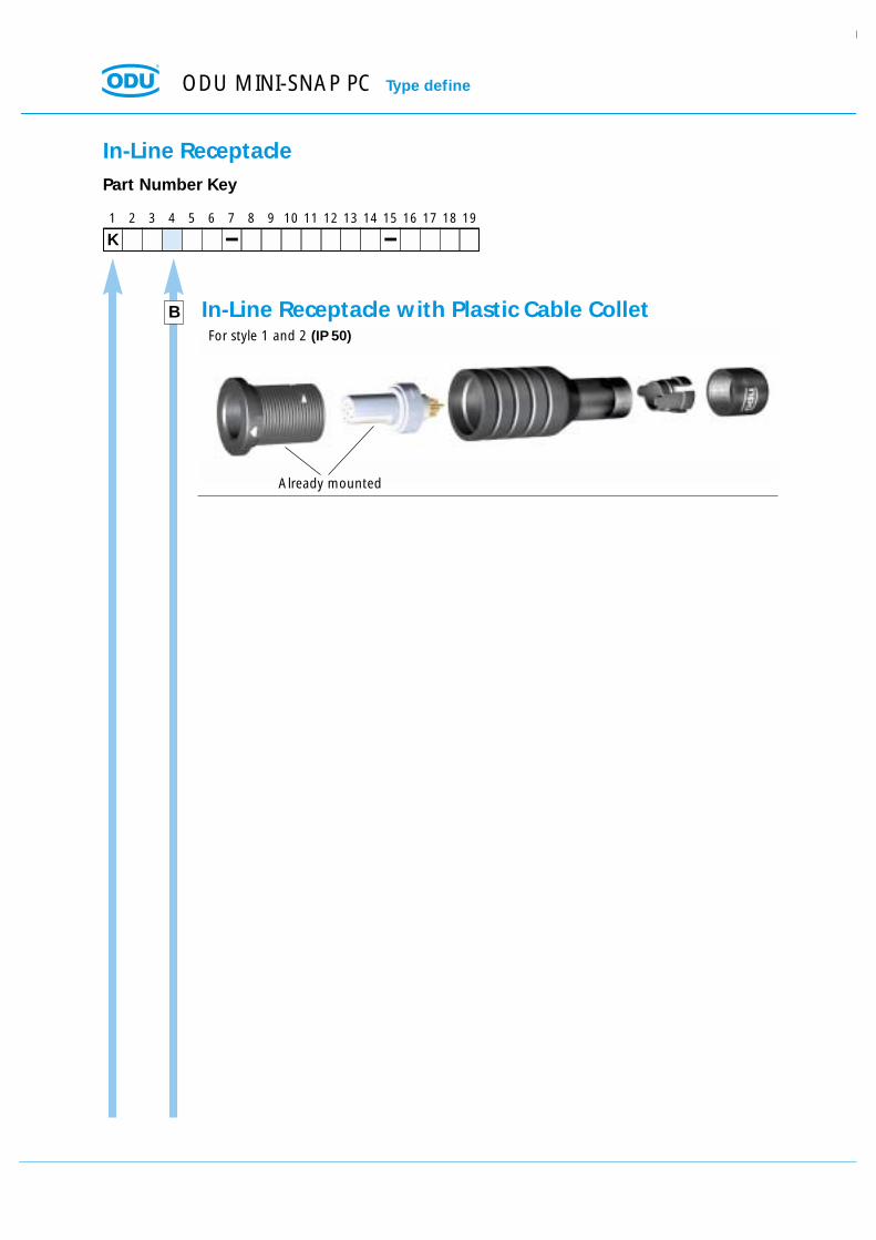
ODU MINI-SNAP PC Type define
1 2 3 4 5 6 7 8 9 10 11 12 13 14 15 16 17 18 19
Part Number Key
B
K
In-Line Receptacle
In-Line Receptacle with Plastic Cable ColletFor style 1 and 2 (IP 50)
Already mounted

ODU Steckverbindungssysteme GmbH & Co. KG, Pregelstr. 11, D-84453 Mühldorf/Inn, Tel. +49/86 31/61 56-0, Fax +49/86 31/61 56 49, www.odu.de Seite 35
Contact Configuration
PCB and solder contacts are factory-installed in the insulation body.Crimp contacts are shipped separately.
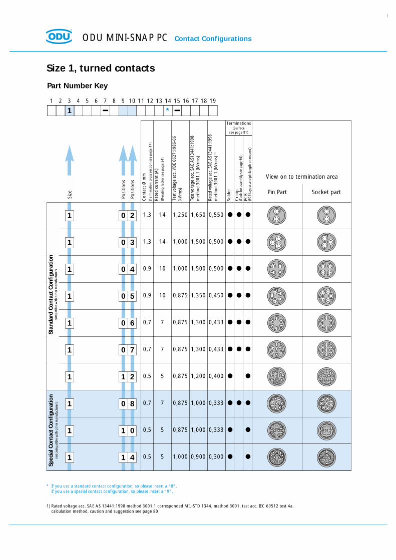
ODU MINI-SNAP PC Contact Configurations
Size
1
Posi
tions
Posi
tions
1 2 3 4 5 6 7 8 9 10 11 12 13 14 15 16 17 18 19
1 *
Part Number Key
0 4
Con
tact
Ø m
m(T
erm
inat
ion
cros
s se
ctio
n se
e pa
ge 4
7)
Rate
d cu
rren
t (A
)(D
erat
ing
fact
or s
ee p
age
54)
Test
vol
tage
acc
. VD
E 06
27:1
986-
06
(kV
rms)
Sold
er
Crim
p(T
ools
for a
ssem
bly
see
page
66)
PCB
(PC
B La
yout
and
pin
leng
th o
n re
ques
t )
Pin Part Socket part
View on to termination area
1
2
4
31
2
4
3
1 0 3
1 0 5 1
2
4
5
3
1
24
5
3
1 0 6 12
3
4 5
6
1 2
3
45
6
1 0 7
1 1 2
1 0 8
1 1 0
1 1 4
12
3
1
23
1 0 2 1,3 14 1,250 1,650 0,550
1,3 14 1,000 1,500 0,500
0,9 10 1,000 1,500 0,500
0,9 10 0,875 1,350 0,450
0,7 7 0,875 1,300 0,433
0,7 7 0,875 1,300 0,433
0,5 5 0,875 1,200 0,400
0,7 7 0,875 1,000 0,333
0,5 5 0,875 1,000 0,333
0,5 5 1,000 0,900 0,300
1
2
1
2
Size 1, turned contacts
Stan
dard
Con
tact
Con
figu
rati
onco
mpa
tible
with
oth
er m
anuf
actu
rers
Test
vol
tage
acc
. SA
E A
S134
41:1
998
met
hod
3001
.1 (k
Vrm
s)
Rate
d vo
ltage
acc
. SA
E A
S134
41:1
998
met
hod
3001
.1 (k
Vrm
s) 1)
1
2 7
3
4 5
6
12
3
45
6
7
45
6 3 12
11
1098
71 2
4 5
6312
11
109 8
712
Spec
ial C
onta
ct C
onfig
urat
ion
not c
ompa
tible
with
oth
er m
anuf
actu
rers
Terminations(Surface
see page 81)
1) Rated voltage acc. SAE AS 13441:1998 method 3001.1 corresponded MIL-STD 1344, method 3001, test acc. IEC 60512 test 4a.calculation method, caution and suggestion see page 80
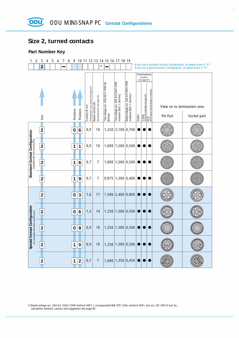
* If you use a standard contact configuration, so please insert a “0”.If you use a special contact configuration, so please insert a “9”.
Contact Configurations ODU MINI-SNAP PC
Size
1
Posi
tions
Posi
tions
1 2 3 4 5 6 7 8 9 10 11 12 13 14 15 16 17 18 19
1 *
Part Number Key
0 8
Con
tact
Ø m
m(T
erm
inat
ion
cros
s se
ctio
n se
e pa
ge 4
8)
Rate
d cu
rren
t (A
)(D
erat
ing
fact
or s
ee p
age
54)
Test
vol
tage
acc
. VD
E 06
27:1
986-
06
(kV
rms)
Sold
er
Crim
p(T
ools
for a
ssem
bly
see
page
66)
PCB
only
soc
ket
(PC
B La
yout
and
pin
leng
th o
n re
ques
t )
Pin Part Socket part
View on to termination area
1 0 7 1
2 7
3
4 5
6
12
3
45
6
7
1 0 6 0,7 4 0,750 1,300 0,433
0,7 4 0,750 1,300 0,433
0,7 4 0,750 1,000 0,333
12
3
4 5
6
1 2
3
45
6
Size 1, stamped and formed contacts
Stan
dard
1*
Test
vol
tage
acc
. SA
E A
S134
41:1
998
met
hod
3001
.1 (k
Vrm
s)
Rate
d vo
ltage
acc
. SA
E A
S134
41:1
998
met
hod
3001
.1 (k
Vrm
s) 1)
Spec
ial 2*
Terminations(Surface
see page 81)
1) Rated voltage acc. SAE AS 13441:1998 method 3001.1 corresponded MIL-STD 1344, method 3001, test acc. IEC 60512 test 4a.calculation method, caution and suggestion see page 80
2) The stamped crimp contacts are only with PEEK insulator available
1* = Standard Contact Configurationcompatible with other manufacturers
2* = Special Contact Configurationnot compatible with other manufacturers
* If you use a standard contact configuration, so please insert a “0”.If you use a special contact configuration, so please insert a “9”.
ODU MINI-SNAP PC Contact Configurations
Size
2
Posi
tions
Posi
tions
1 2 3 4 5 6 7 8 9 10 11 12 13 14 15 16 17 18 19
2 *
Part Number Key
1 6
Con
tact
Ø m
m(T
erm
inat
ion
cros
s se
ctio
n se
e pa
ge 4
7)
Rate
d cu
rren
t (A
)(D
erat
ing
fact
or s
ee p
age
54)
Test
vol
tage
acc
. VD
E 06
27:1
986-
06
(kV
rms)
Sold
er
Crim
p(T
ools
for a
ssem
bly
see
page
66)
PCB
(PC
B La
yout
and
pin
leng
th o
n re
ques
t )
Pin Part Socket part
View on to termination area
4
3
2
1
6
59
8
7
1011
12
13
14
1516
4
32
16
5
9
87
10
1112
13
14
15
16
2 1 1
2 1 9 4
3
21
6
5
9
8
7
10
11
1213
14
15
17
1819
16
43
21
6
5
9
8
7
10
11
1213
14
15
17
1819
16
2 0 3
2 0 6
2 0 8
2 1 0
4
57
8
910
11 23
1
6
4
57
8
9 10
112 31
6
2 0 6 0,9 10 1,250 2,100 0,700
0,9 10 1,000 1,500 0,500
0,7 7 1,000 1,500 0,500
0,7 7 0,875 1,200 0,400
1,6 17 1,500 2,400 0,800
1,3 14 1,250 1,500 0,500
0,9 10 1,250 1,500 0,500
0,9 10 1,250 1,500 0,500
1
2
3
4
56
1
2
3
4
5
6
Size 2, turned contacts
Stan
dard
Con
tact
Con
figu
rati
onco
mpa
tible
with
oth
er m
anuf
actu
rers
Test
vol
tage
acc
. SA
E A
S134
41:1
998
met
hod
3001
.1 (k
Vrm
s)
Rate
d vo
ltage
acc
. SA
E A
S134
41:1
998
met
hod
3001
.1 (k
Vrm
s) 1)
2 1 2 0,7 7 1,000 1,350 0,450
Spec
ial C
onta
ct C
onfig
urat
ion
not c
ompa
tible
with
oth
er m
anuf
actu
rers
Terminations(Surface
see page 81)
1) Rated voltage acc. SAE AS 13441:1998 method 3001.1 corresponded MIL-STD 1344, method 3001, test acc. IEC 60512 test 4a.calculation method, caution and suggestion see page 80
* If you use a standard contact configuration, so please insert a “0”.If you use a special contact configuration, so please insert a “9”.

Contact Configurations ODU MINI-SNAP PC
Size
2
Posi
tions
Posi
tions
1 2 3 4 5 6 7 8 9 10 11 12 13 14 15 16 17 18 19
2 *
Part Number Key
1 4
Con
tact
Ø m
m(T
erm
inat
ion
cros
s se
ctio
n se
e pa
ge 4
7)
Rate
d cu
rren
t (A
)(D
erat
ing
fact
or s
ee p
age
48)
Test
vol
tage
acc
. VD
E 06
27:1
986-
06
(kV
rms)
Sold
er
Crim
p(T
ools
for a
ssem
bly
see
page
66)
PCB
(onl
y so
cket
s)2)
(PC
B La
yout
and
pin
leng
th o
n re
ques
t )
Pin Part Socket part
View on to termination area
2 1 2
2 1 6 0,7 4 0,750 1,500 0,500
0,7 4 0,750 1,350 0,450
0,7 4 0,750 1,200 0,400
4
3
2
1
6
59
8
7
1011
12
13
14
1516
4
32
16
5
9
87
10
1112
13
14
15
16
Size 2, stamped and formed contacts
Stan
dard
1*
Test
vol
tage
acc
. SA
E A
S134
41:1
998
met
hod
3001
.1 (k
Vrm
s)
Rate
d vo
ltage
acc
. SA
E A
S134
41:1
998
met
hod
3001
.1 (k
Vrm
s) 1)
Spec
ial 2*
Terminations(Surface
see page 82)
1) Rated voltage acc. SAE AS 13441:1998 method 3001.1 corresponded MIL-STD 1344, method 3001, test acc. IEC 60512 test 4a.calculation method, caution and suggestion see page 80
2) The stamped crimp contacts are only with PEEK insulator available
1* = Standard Contact Configurationcompatible with other manufacturers
2* = Special Contact Configurationnot compatible with other manufacturers
* If you use a standard contact configuration, so please insert a “0”.If you use a special contact configuration, so please insert a “9”.

ODU MINI-SNAP PC Contact Configurations
Size
3
Posi
tions
Posi
tions
1 2 3 4 5 6 7 8 9 10 11 12 13 14 15 16 17 18 19
3 *
Part Number Key
2 7
Con
tact
Ø m
m(T
erm
inat
ion
cros
s se
ctio
n se
e pa
ge 4
7)
Rate
d cu
rren
t (A
)(D
erat
ing
fact
or s
ee p
age
54)
Test
vol
tage
acc
. VD
E 06
27:1
986-
06
(kV
rms)
Sold
er
Crim
p(T
ools
for a
ssem
bly
see
page
66)
PCB
(PC
B La
yout
and
pin
leng
th o
n re
ques
t )
Pin Part Socket part
View on to termination area
17 16
15
1456
18
19
12
3
47
8
20
21
22
2324
1011
9
12
13
27
26
25
515
16 1718
197
6
21
12
13
27
26
25
1110
2423
93
8
20
21
22
414
3 2 4
3 0 4
3 0 7
3 0 8
3 1 4
3 1 8
3 2 0
3 2 2
13
141516
17
18
8
7
6 512
41
1124
232221
209
10
3
2
19
13
14 1516
17
18
8
7
6512
41
1124
23 2221
209
10
3
2
19
3 1 5 0,9 10 1,000 1,650 0,550
0,7 7 1,000 1,200 0,400
0,7 7 1,000 1,200 0,400
2,0 22 1,500 1,500 0,500
1,6
1,3
17
14
1,250 1,800 0,600
1,250 1,650 0,550
0,9 10 1,250 1,350 0,450
0,9 10 1,000 1,350 0,450
0,7 7 1,000 1,100 0,366
0,7 7 0,875 1,100 0,366
17
2
89
10
3
4
5 6
15
1413
12
11
17
2
89 10
3
4
56
15
14
13 12
11
Size 3, turned contacts
Stan
dard
Con
tact
Con
figu
rati
onco
mpa
tible
with
oth
er m
anuf
actu
rers
Test
vol
tage
acc
. SA
E A
S134
41:1
998
met
hod
3001
.1 (k
Vrm
s)
Rate
d vo
ltage
acc
. SA
E A
S134
41:1
998
met
hod
3001
.1 (k
Vrm
s) 1)
3 2 6 0,7 7 0,875 1,000 0,333
Spec
ial C
onta
ct C
onfig
urat
ion
not c
ompa
tible
with
oth
er m
anuf
actu
rers
Terminations(Surface
see page 81)
1) Rated voltage acc. SAE AS 13441:1998 method 3001.1 corresponded MIL-STD 1344, method 3001, test acc. IEC 60512 test 4a.calculation method, caution and suggestion see page 80
* If you use a standard contact configuration, so please insert a “0”.If you use a special contact configuration, so please insert a “9”.

Contact Configurations ODU MINI-SNAP PC
Size
3
Posi
tions
Posi
tions
1 2 3 4 5 6 7 8 9 10 11 12 13 14 15 16 17 18 19
3 *
Part Number Key
2 0
Con
tact
Ø m
m(T
erm
inat
ion
cros
s se
ctio
n se
e pa
ge 4
8)
Rate
d cu
rren
t (A
)(D
erat
ing
fact
or s
ee p
age
54)
Test
vol
tage
acc
. VD
E 06
27:1
986-
06
(kV
rms)
Sold
er
Crim
p(T
ools
for a
ssem
bly
see
page
66)
PCB
(onl
y so
cket
s)2)
(PC
B La
yout
and
pin
leng
th o
n re
ques
t )
Pin Part Socket part
View on to termination area
3 2 7
17 16
15
1456
18
19
12
3
47
8
20
21
22
2324
1011
9
12
13
27
26
25
515
16 1718
197
6
21
12
13
27
26
25
1110
2423
93
8
20
21
22
414
3 2 4 0,7 4 0,750 1,200 0,400
0,7 4 0,750 1,200 0,400
0,7 4 0,750 1,100 0,366
13
141516
17
18
8
7
6 512
41
1124
232221
209
10
3
2
19
13
14 1516
17
18
8
7
6512
41
1124
23 2221
209
10
3
2
19
Size 3, stamped and formed contacts
Stan
dard
1*
Test
vol
tage
acc
. SA
E A
S134
41:1
998
met
hod
3001
.1 (k
Vrm
s)
Rate
d vo
ltage
acc
. SA
E A
S134
41:1
998
met
hod
3001
.1 (k
Vrm
s) 1)
Terminations(Surface
see page 82)
1) Rated voltage acc. SAE AS 13441:1998 method 3001.1 corresponded MIL-STD 1344, method 3001, test acc. IEC 60512 test 4a.calculation method, caution and suggestion see page 80
2) The stamped crimp contacts are only with PEEK insulator available
1* = Standard Contact Configurationcompatible with other manufacturers
2* = Special Contact Configurationnot compatible with other manufacturers
3 2 2 0,7 4 0,750 1,100 0,366
3 2 6 0,7 4 0,750 1,000 0,333
Spec
ial 2*
* If you use a standard contact configuration, so please insert a “0”.If you use a special contact configuration, so please insert a “9”.

ODU MINI-SNAP PC For your notes

Details for thePart Number Key
Coding SystemHousing Materials / Surfaces
Insulation Body MaterialContact Type / Surface / Diameter
Contact Termination Cross Section (AWG)Collet System
Bend Protection Sleeves

8
3
Standard
Plastic, black similar RAL 9004
Plastic, white similar RAL 9002(shielded version not in white colour available)
Housing
Part Number Key
1 2 3 4 5 6 7 8 9 10 11 12 13 14 15 16 17 18 19
ReceptacleFront View
1
2
9
Coding
1 2 3 4 5 6 7 8 9 10 11 12 13 14 15 16 17 18 19
Part Number Key
Size
1 2 3
ODU MINI-SNAP PC Details for the Part Number Key
Special Coding (not compatible)
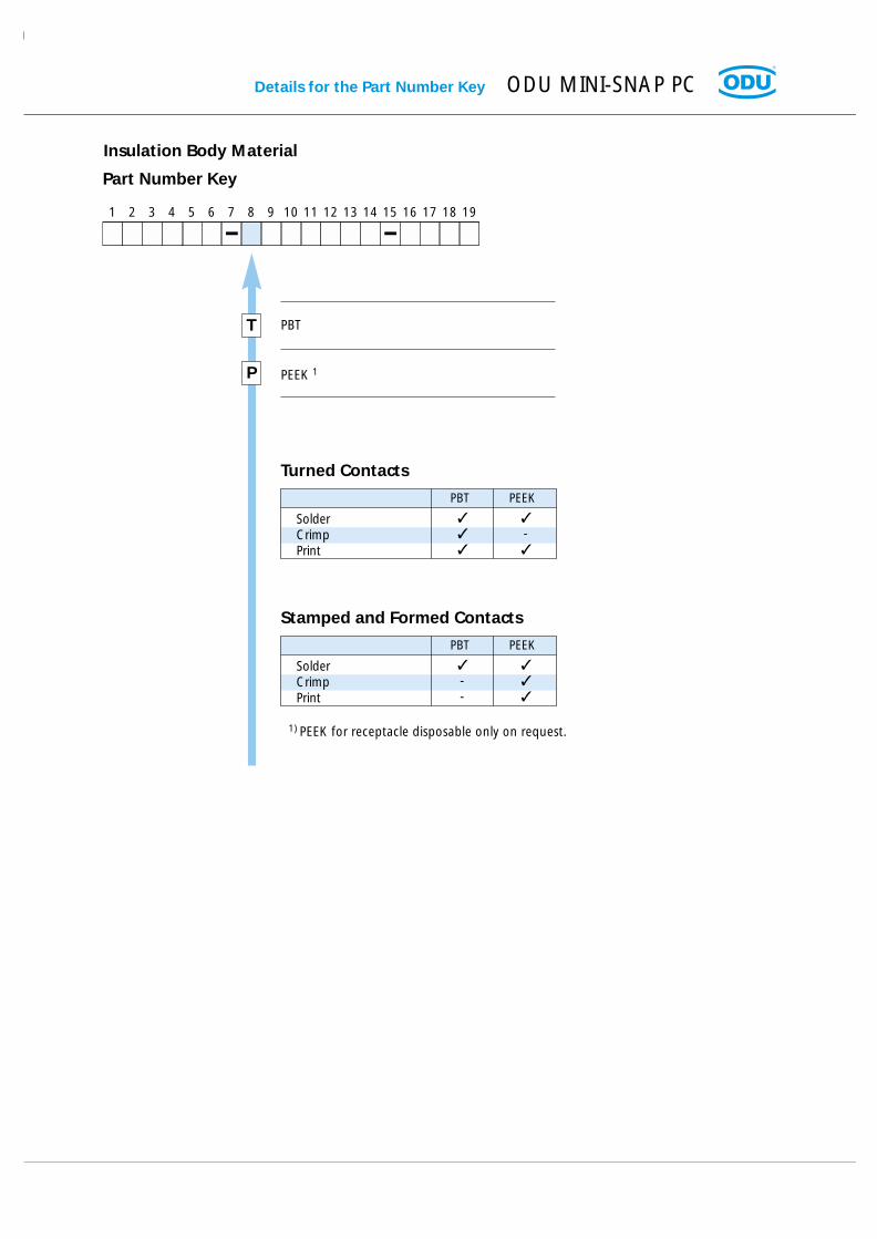
PBT
PEEK 1
T
P
1) PEEK for receptacle disposable only on request.
Insulation Body Material
Details for the Part Number Key ODU MINI-SNAP PC
Part Number Key
Turned Contacts
1 2 3 4 5 6 7 8 9 10 11 12 13 14 15 16 17 18 19
PBT PEEK
SolderCrimpPrint
-
Stamped and Formed Contacts
PBT PEEK
SolderCrimpPrint
--

ODU MINI-SNAP PC Details for the Part Number Key
Contact Type / Contact Surface - Contact Diameter
Part Number Key
1 2 3 4 5 6 7 8 9 10 11 12 13 14 15 16 17 18 19
L
M
N
P
Q
R
1
2
3
4
5
ContactØType Surface
Socket
Pin
Socket
Pin
Socket
Pin
Socket
Pin
Socket
Pin
Socket
L - 0,75 µm Au (min.)
L - 0,75 µm Au (min.)
C- 0,75 µm Au (min.)
C - 0,75 µm Au (min.)
P - 0,75 µm Au (min.)
P - 0,75 µm Au (min.)
L - 0,75 µm Au (min.)
L - 0,75 µm Au (min.)
C- 0,75 µm Au (min.)
C - 0,75 µm Au (min.)
P - 0,75 µm Au (min.)
0,50
0,70
0,90
mixed
1,30
1,50
1,60
2,00
3,00
4,00
L = Solder termination
C = Crimp termination
P = PCB termination
* = Only with Ø 0,7 mm available
C
F
J
M
P
Q
S
T
V
W
Has
to m
ach
with
sel
ecte
d co
ntac
t ins
erts
(Pag
e 35
)
Turn
ed C
onta
cts
* St
ampe
d C
onta
cts
0,5 0,4 28 0,08
0,7 0,6 26 0,15
0,9 0,85 22 0,38
1,3 1,1 20 0,50
1,6 1,5 18 1,00
2,0 1,85 14 1,5
2,0 2,4 2,5
ContactØ
Term.Ø AWG
Term. Cross
mm2
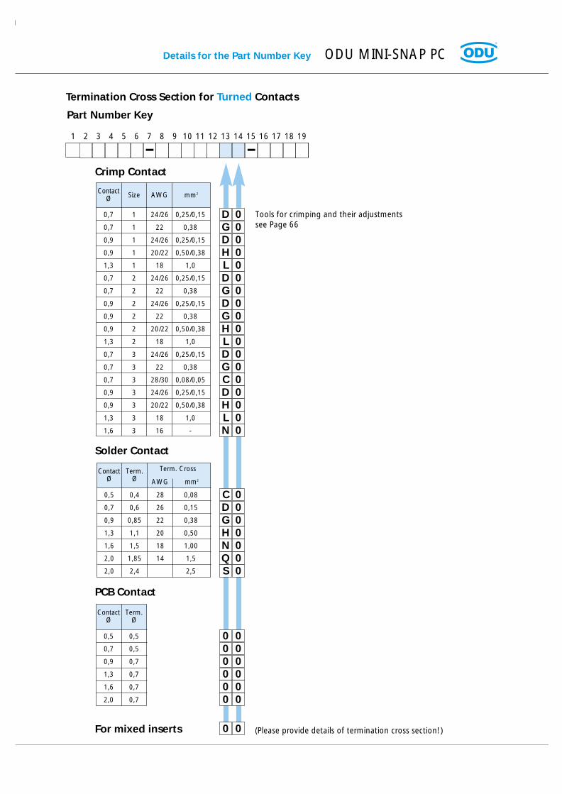
Details for the Part Number Key ODU MINI-SNAP PC
Termination Cross Section for Turned Contacts
Part Number Key
1 2 3 4 5 6 7 8 9 10 11 12 13 14 15 16 17 18 19
0D0G0D0H0L0D0G0D0G0H0L0D0G0C0D0H0L0N
0,7 1 24/26 0,25/0,15
0,7 1 22 0,38
0,9 1 24/26 0,25/0,15
0,9 1 20/22 0,50/0,38
1,3 1 18 1,0
0,7 2 24/26 0,25/0,15
0,7 2 22 0,38
0,9 2 24/26 0,25/0,15
0,9 2 22 0,38
0,9 2 20/22 0,50/0,38
1,3 2 18 1,0
0,7 3 24/26 0,25/0,15
0,7 3 22 0,38
0,7 3 28/30 0,08/0,05
0,9 3 24/26 0,25/0,15
0,9 3 20/22 0,50/0,38
1,3 3 18 1,0
1,6 3 16 -
ContactØ Size AWG mm2
Tools for crimping and their adjustmentssee Page 66
Crimp Contact
0C0D0G0H0N0Q0S
000000000000
00
0,5 0,5
0,7 0,5
0,9 0,7
1,3 0,7
1,6 0,7
2,0 0,7
ContactØ
Term.Ø
(Please provide details of termination cross section!)
Solder Contact
PCB Contact
For mixed inserts
ODU MINI-SNAP PC Details for the Part Number Key
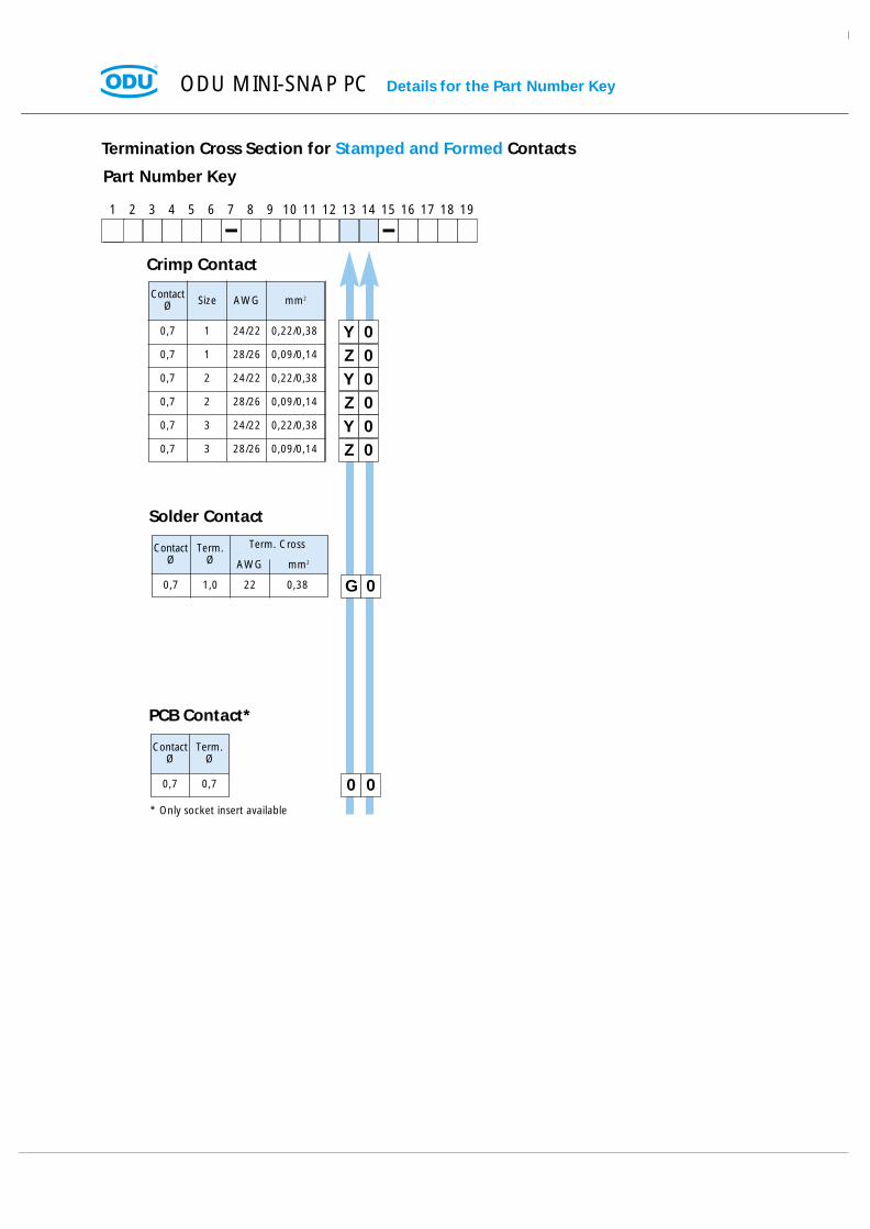
Termination Cross Section for Stamped and Formed Contacts
Part Number Key
1 2 3 4 5 6 7 8 9 10 11 12 13 14 15 16 17 18 19
0Y0Z0Y0Z0Y0Z
0,7 1 24/22 0,22/0,38
0,7 1 28/26 0,09/0,14
0,7 2 24/22 0,22/0,38
0,7 2 28/26 0,09/0,14
0,7 3 24/22 0,22/0,38
0,7 3 28/26 0,09/0,14
ContactØ Size AWG mm2
Crimp Contact
0G
00
0,7 1,0 22 0,38
ContactØ
Term.Ø AWG
Term. Cross
mm2
0,7 0,7
ContactØ
Term.Ø
Solder Contact
PCB Contact*
* Only socket insert available

Plastic cable collet for the Types B & D (Page 32 and 34)
Details for the Part Number Key ODU MINI-SNAP PC
6
7
9
0
0
0
5
0
2
0
X X
Cable diameterin mm
Size
1 2 3
> 1,5 - 3,0
> 3,1 - 4,5
> 4,6 - 6,0
> 6,1 - 7,5
> 7,6 - 9,0
> 9,1 - 10,5
Part Number Key
21 3 4 5 6 7 8 9 10 11 12 13 14 15 16 17 18 19
4 5
3 0
without collet nut
with all collet nuts
Insert: for all Plugs and In-Line Receptaclesof the Types B & D
Application: Collet Nut for strain relief.

4
4
5
5
6
6
7
7
8
8
9
9
0
0
0
5
0
5
0
5
0
5
0
5
0
5
1
2
0 3
0 0
Cable diameterin mm
Size
1 2 3
> 2,5 - 3,0
> 3,0 - 3,5
> 3,5 - 4,0
> 4,0 - 4,5
> 4,5 - 5,0
> 5,0 - 5,5
> 5,5 - 6,0
> 6,0 - 6,5
> 6,5 - 7,0
> 7,0 - 7,5
> 7,5 - 8,0
> 8,0 - 8,5
> 8,5 - 9,0
> 9,0 - 9,5
> 9,5 - 10,0
> 10,0 - 10,5
> 10,5 - 11,0
Collet System for the Types A & C (Page 32)
Insert: for all Plugs and In-Line Receptaclesof the Types A & C.
Application: Collet nut for strain relief,EMI ring for conductive pathbetween shield and housing.
EMI Ring
Collet Nut
Cable-Ø
Anti Rotation Pin
without collet system
Part Number Key
1 2 3 4 5 6 7 8 9 10 11 12 13 14 15 16 17 18 19
3 5
3 0
ODU MINI-SNAP PC Details for the Part Number Key
Details for the Part Number Key ODU MINI-SNAP PC
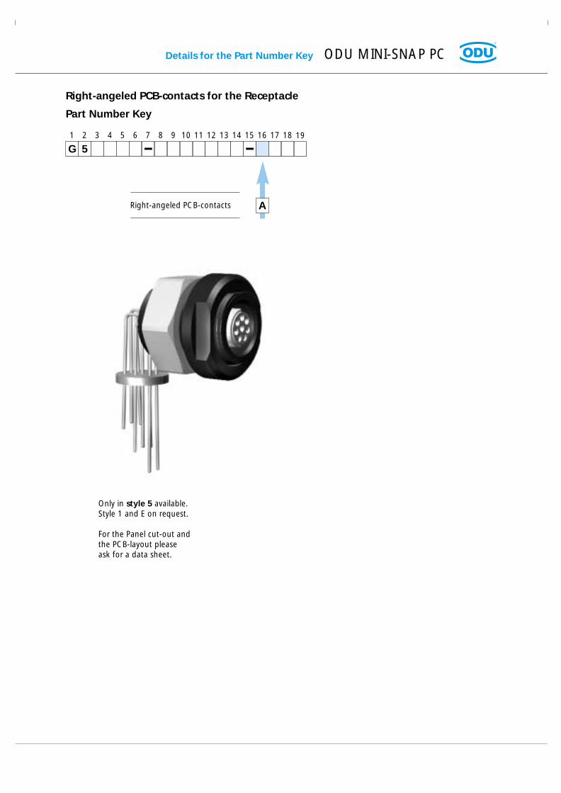
Right-angeled PCB-contacts for the Receptacle
Right-angeled PCB-contacts
Part Number Key
21 3 4 5 6 7 8 9 10 11 12 13 14 15 16 17 18 19
5G
A
Only in style 5 available.Style 1 and E on request.
For the Panel cut-out andthe PCB-layout pleaseask for a data sheet.

A
B
C
D
E
F
G
H
J
K
L
M
P
00
Cable Bend Relief
red RAL 3020
white RAL 9010
yellow RAL 1016
green RAL 6029
blue RAL 5002
grey RAL 7005
black RAL 9005
orange RAL 2004
purple RAL 4005
brown RAL 8016
light green RAL 6018
light blue RAL 5012
Material
PUR
without cable bend relief
Color of the Cable Bend Relief
Color / RAL-Number(similar)
Part Number Key
1 2 3 4 5 6 7 8 9 10 11 12 13 14 15 16 17 18 19
(see page 62)
Temperature rangePUR -40 ºC up to +80 ºC
Short-term up to +120 ºC
ODU MINI-SNAP PC Details for the Part Number Key

Tech
nic
al In
form
atio
ns
for
the
OD
U M
INI-
SNA
P PC
Technical Informationsfor the ODU MINI-SNAP PC

ODU MINI-SNAP PC Technical Information
Current Load - Turned Contacts
Nominal Single Contact Current Load for pin / slotted socket(Nominal Diameter 0.5 mm - 1.6 mm)
0 1 2 3 4 5 6 7 8 9 10 11 12 13 14 15 16 17 18 19 20 21
100
90
80
70
60
50
40
30
20
10
Ø 0,5 mm Ø 0,7 mm Ø 0,9 mm Ø 1,3 mm
Ø 1,6 mm
Upper Maximum Temperature for Standard Contacts: + 120 °C
Test contact was terminated to largest possible conductor.
Connectors or cables with more than one contact or conductor generate a higher temperature than a single contact.Therefore, a Derating Factor must be applied. For connectors the Derating Factor is applied according to DIN 57298 part 2 / VDE 0298 part 2. The Derating Factor is used starting with 5 loaded wires. (DIN 41 640 T 3)
Derating Factor:
5 0,757 0,65
10 0,5514 0,5019 0,4524 0,40
Number of loaded wires Derating Factor
Incr
ease
of
tem
per
atu
res
(K)
Load Current (A)

Technical Information ODU MINI-SNAP PC
Current Load - Stamped and Formed Contacts
Nominal Single Contact Current Load for pin / slotted socket(Nominal diameter 0,7 mm)
0 1
1 2 3 4
2 3 4 5 6 7 8
100
90
80
70
60
50
40
30
20
10
Mating Force: ..~ 0,35... NDemating Force: ..~ 0,33... N
Conclusion: The diagram shows that the connector under a current load of 4 Awill reach a temperature of approx. 54 K with connection AWG 28will reach a temperature of approx. 44 K with connection AWG 26will reach a temperature of approx. 34 K with connection AWG 24will reach a temperature of approx. 27 K with connection AWG 22
Incr
ease
of
tem
per
atu
res
(K)
Load Current (A)
1 Termination Cross Section: AWG 282 Termination Cross Section: AWG 263 Termination Cross Section: AWG 244 Termination Cross Section: AWG 22

Housing (standard) PEI (GF)Back Nut Polyetherimid –Sleeve
Housing (shielded) PEI (GF) Partial: + 5 µm CuPolyetherimid + 2 µm Ni
Collet (Type B & D) PES –Polyethersulfon
Collet (Type A & C)EMI-RingHalf-Shells Cu-alloy Ni matt 6-8 µmNut
Turned Contacts Cu-alloy + 1,25 µm Ni+ 0,75 µm Au
+ 1,25 µm NiStamped and formed Cu-alloy + 0,75 µm Au on thecontacts mating area
+ 3,00 µm Sn on thetermination area
ODU MINI-SNAP PC Technical Information
Norm Unit PBT PEEK
Housing materials / Surfaces
Insulation Body Material (UL 94 V-0 rated)
Material Surface
Component Parts Designation Thickness of the film
Dialectric Strenght DIN ASTM KV / mm 30 1953481 D-149
Operating Temperature -- -- °C - 40 / + 140 -50 / +250Flammability rating UL–94 -- -- V-0 V-0Creeping distance IEC (V) 275 175acc. to CTI 60112

Technical Information ODU MINI-SNAP PC
Mating Force, Demating Force and Pull-Off-Force(All details are for the standard housing without insert)
* After an inadvertment pull-out the plug can used again.
Mating Force max. 2,5 N max. 2,8 N max. 3 N
Demating Force max. 2,6 N max. 2,8 N max. 3 N
Pull-Off-Force* min. 80 N min. 80 N min.. 85 N
Size 1 Size 2 Size 3

0
-10
-20
-30
-40
-50
-60
-70
-80
0,01 0,10 1,00 10,00Frequency in GHz
Att
enu
atio
n in
dB
ODU MINI-SNAP PC Technical Information
Electromagnetic Compatibility (EMC)
When discussing electromagnetic compatibility (EMC) we nned take into account not only the device, circuit etc. but moreover the entire network and communication links and interconnections. This involves all connectingelements such as conductors and connectors. Electromagnetic interference from the outside into the connectorcan lead to system malfunctioning. The best way to prevent this is by providing a high-quality shield between thecable and the connector. In order to provide reliable EMC data to our customers we engaged the services of acertified test laboratory to investigate the EMC characteristics of the ODU MINI-SNAP PC. They tested for us Size00, 0, 1, 2 and 3 MINI-SNAP connectors.
Measurements were conducted using the inductive wire or parallel wire method in accordance with test procedure VG 55214-6-2. In this set-up, the mated connector is connected on one end to a network analyzer and terminated on the other end with a suitable impedance. The inductive wire is then mounted in close proximity along the mated connector pair. The induction wire is a ribbon cable which permits to vary the level ofinduction by using more or less of the ribbon conductors.
Next, a signal with a frequency range of 100 kHz to2,5 GHz is connected to the ribbon cable. The networkanalyzer is used to measure the amount of signal inducedinto the connector circuit. The result is shown as the shiel-ding attenuation AT in dB. It is essential that all leads to theconnector are shielded so that no signal can be induced into the circuit at any other place except the connector. The various attenuation values are plotted on a logarithmicscale as attenuation in dB vs. frequency.
Network Analyzer
Attenuator 20 dBPower Devider Termination Impedance
Termination Impedance Object under Test
Inductive wire
Tape CouplerCoupler

Technical Information ODU MINI-SNAP PC
Autoclaving of ODU MINI-SNAP Connectors
If required ODU can deliver MINI-SNAP connectors for the following sterilization process:Steam-sterilization with pre-vacuum or gravitation-process. Connectors were tested with autoclave equipment withreference to DIN EN 13 060 at 134° C and 200 cycles.
Sterilization Curve:
For other sterilization-processes please contact our technical support team.
3000
2000
1013
0
pressure inmbar abs.
time
1. P
re-v
acuu
m
1. P
ress
ure
incr
ease
1. P
ress
ure
incr
ease
Ventilation Increase ofpressure Sterilization
Sterilization Curve
Drying
2. P
re-v
acuu
m
2. P
ress
ure
incr
ease
Tem
pera
ture
incr
ease
in t
rans
ition
Influ
ence
5 m
in. a
t 13
4 °C
15
min
. at
121
°C
Pres
sure
dec
reas
e
Aft
er-v
acuu
m
Dry
ing
time
Vent
ilatio
n

ODU MINI-SNAP PC For your notes
Acc
esso
ries
/ T
oo
lsPa
ckin
g In
form
atio
n
AccessoriesTools
Packing Information
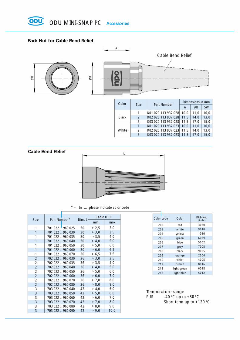
Dimensions in mmSize Part Number
A ØB SWColor
123123
Black
White
K01 020 113 937 028K02 020 113 937 028K03 020 113 937 028K01 020 113 937 023K02 020 113 937 023K03 020 113 937 023
10,011,511,510,011,511,5
11,0 14,017,011,0 14,017,0
10,0 13,015,010,0 13,015,0
Back Nut for Cable Bend Relief
SW ØB
A
Cable Bend Relief
Cable O.D.Size Part Number* Dim. L
min. max.
11111112222222333333
701 022 ... 960 025701 022 ... 960 030701 022 ... 960 035701 022 ... 960 040701 022 ... 960 050701 022 ... 960 060701 022 ... 960 070702 022 ... 960 030702 022 ... 960 035702 022 ... 960 040702 022 ... 960 050702 022 ... 960 060702 022 ... 960 070702 022 ... 960 080703 022 ... 960 040703 022 ... 960 050703 022 ... 960 060703 022 ... 960 070703 022 ... 960 080703 022 ... 960 090
3030303030303036363636363636424242424242
> 2,5> 3,0> 3,5> 4,0> 5,0> 6,0> 6,5> 3,0> 3,5> 4,0> 5,0> 6,0> 7,0> 8,0> 4,0> 5,0> 6,0> 7,0> 8,0> 9,0
3,03,54,05,06,06,57,53,54,05,06,07,08,09,05,06,07,08,09,010,0
Color code
202203204205206207208209210212215216
Color
redwhiteyellowgreenbluegreyblack
orangevioletbrown
light greenlight blue
RAL-No.
302090101016602950027005900520044005801660185012
LCable Bend Relief
(similar)
* = In ... please indicate color code
Temperature rangePUR -40 ºC up to +80 ºC
Short-term up to +120 ºC
ODU MINI-SNAP PC Accessories

L
t = Thickness
B
SW
b
Protective Cover for IP50 and IP68 (for all receptacle styles)
Part number No. SW t B L b
Spanner Wrench
598.700.001.012.000 11 11 2 24,5 115 10598.700.001.004.000 13 13 2,5 30,5 98 16,5598.700.001.007.000 16 16 3 35,5 145 15598.700.001.008.000 17 17 3 35,5 145 15598.700.001.013.000 19 19 3 40,0 100 18598.700.001.014.000 24 24 3 54,0 215 22
B
C
A
C
Dimensions in mmSize Part Number
A B C
123
K01 097 006 933 .0.K02 097 006 933 .0.K03 097 006 933 .0.
15,111,511,5
17 14,017,0
~75 ~85~100
With . please, register desired lanyard material0 = Polyamid lanyard with loop1 = Stainless steel lanyard with loop2 = Polyamid lanyard with solder lug3 = Stainless steel lanyard with solder lug
With . please, register desired colour of the cap*3 = White cap8 = Black cap
* = If you use a polyamid lanyard, the colour iscorresponding with the colour of the cap.
Accessories ODU MINI-SNAP PC

ODU MINI-SNAP PC For your notes
ODU Steckverbindungssysteme GmbH & Co. KG, Pregelstr. 11, D-84453 Mühldorf/Inn, Tel. +49/86 31/61 56-0, Fax +49/86 31/61 56 49, www.odu.de Seite 65
Tools
ODU MINI-SNAP PC Tools
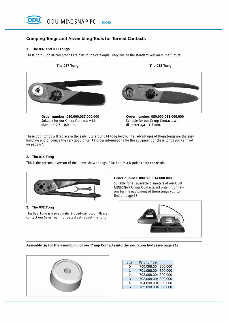
Crimping Tongs and Assembling Tools for Turned Contacts
1. The 037 and 038 Tongs
These both 8-point-crimptongs are new in the catalogue. They will be the standard version in the furture.
2. The 014 Tong
This is the precursor version of the above shown tongs. Also here is a 8-point-crimp the result.
3. The 032 Tong
This 032 Tong is a pneumatic 8-point-crimptool. Pleasecontact our Sales Team for Datasheets about this tong
These both tongs will replace in the early future our 014 tong below. The advantages of these tongs are the easyhandling and of course the very good price. All order informations for the equipment of these tongs you can findon page 67.
The 037 Tong
Order number: 080.000.037.000.000Suitable for our Crimp Contacts withdiameter 0,7 – 0,9 mm.
Order number: 080.000.038.000.000Suitable for our Crimp Contacts withdiameter 1,3 – 1,6 mm.
Order number: 080.000.014.000.000
Suitable for all available diameters of our ODUMINI-SNAP Crimp Contacts. All order informati-ons for the equipment of these tongs you canfind on page 68
The 038 Tong
Size Part number0 700.098.004.300.0001 701.098.004.300.0002 702.098.004.300.0003 703.098.004.300.0004 704.098.004.300.0005 705.098.004.300.000
Assembly Jig for the assembling of our Crimp Contacts into the insulation body (see page 71)

Tools ODU MINI-SNAP PC
Assembly Tools for Turned Contactsfor Crimping Tools 037 and 038
Standard Contact Configuration
Position Size AWG mm2
Adjustments forCrimp Tool
080.000.037.000.000for Pin Contact
Insertion ToolAdjustment for
Crimp Tool080.000.038.000.000
for Socket Contact
Positionier
3
4
5
6
7
6
11
16
19
15
24
27
1
1
1
1
1
2
2
2
2
3
3
3
18
24/2622
24/2622
24/2622
24/2622
24/2622
24/2622
24/2622
24/2622
24/2622
24/2622
24/2622
1.0
0.25/0.150.38
0.25/0.150.38
0.25/0.150.38
0.25/0.150.38
0.25/0.150.38
0.25/0.150.38
0.25/0.150.38
0.25/0.150.38
0.25/0.150.38
0.25/0.150.38
0.25/0.150.38
-
4747444447474444474444
5
----------------------
081 701 001 744 038
081 701 001 749 037
081 701 001 749 037
081 701 002 748 037
081 701 002 748 037
081 702 001 749 037
081 702 001 749 037
081 702 002 748 037
081 702 002 748 037
081 702 001 749 037
081 703 003 748 037
081 703 003 748 037
081 701 001 844 038
081 702 001 849 037
081 702 001 849 037
081 701 002 848 037
081 701 002 848 037
081 702 001 849 037
081 702 001 849 037
081 702 002 848 037
081 702 002 848 037
081 703 001 849 037
081 702 002 848 037
081 702 002 848 037
085 180 955 000 000
085 180 689 000 000
085 180 689 000 000
085 180 676 000 000
085 180 676 000 000
085 180 689 000 000
085 180 689 000 000
085 180 677 000 000
085 180 677 000 000
085 180 689 000 000
085 180 677 000 000
085 180 677 000 000
Special Contact Configuration
Position Size AWG mm2
Adjustments forCrimp Tool
080.000.037.000.000for Pin Contact
Insertion ToolAdjustment for
Crimp Tool080.000.038.000.000
for Socket Contact
Positionier
8
3
6
8
10
12
7
8
14
18
20
22
26
1
2
2
2
2
2
3
3
3
3
3
3
3
24/2622
18
18
24/2622
24/2622
24/2622
16
2218
24/2622
24/2622
24/2622
24/2622
24/2622
0.25/0.150.38
1.0
1.0
0.25/0.150.38
0.25/0.150.38
0.25/0.150.38
16
0.381.0
0.25/0.150.38
0.25/0.150.38
0.25/0.150.38
0.25/0.150.38
0.25/0.150.38
44
-
-
474744
-
. -4 74 7444444
--
5
5
------
-
2 5- -- -------
081 701 001 748 037
081 702 001 744 038
081 702 001 744 038
081 702 001 749 037
081 702 001 749 037
081 702 001 748 037
081 703 001 751 038
081 703 001 744 038
081 703 001 749 037
081 703 001 749 037
081 703 002 748 037
081 703 003 748 037
081 703 003 748 037
081 701 002 848 037
081 702 001 844 038
081 702 001 844 038
081 702 001 849 037
081 702 001 849 037
081 702 001 848 037
081 703 001 851 038
081 703 001 844 038
081 703 001 849 037
081 703 001 849 037
081 702 001 848 037
081 702 002 848 037
081 702 002 848 037
085 180 677 000 000
085 180 955 000 000
085 180 955 000 000
085 180 691 000 000
085 180 691 000 000
085 180 676 000 000
085 182 707 000 000
085 180 955 000 000
085 180 689 000 000
085 180 689 000 000
085 180 676 000 000
085 180 677 000 000
085 180 677 000 000
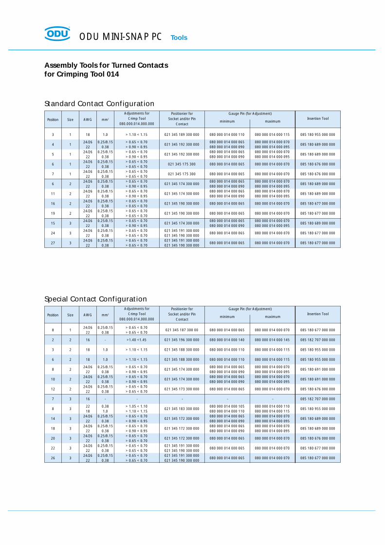
Assembly Tools for Turned Contactsfor Crimping Tool 014
Standard Contact Configuration
Position Size AWG mm2
Adjustments forCrimp Tool
080.000.014.000.000maximum
Insertion ToolPositionier for
Socket and/or PinContact
minimum
Gauge Pin (for Adjustment)
3
4
5
6
7
6
11
16
19
15
24
27
1
1
1
1
1
2
2
2
2
3
3
3
18
24/2622
24/2622
24/2622
24/2622
24/2622
24/2622
24/2622
24/2622
24/2622
24/2622
24/2622
1.0
0.25/0.150.38
0.25/0.150.38
0.25/0.150.38
0.25/0.150.38
0.25/0.150.38
0.25/0.150.38
0.25/0.150.38
0.25/0.150.38
0.25/0.150.38
0.25/0.150.38
0.25/0.150.38
> 1.10 < 1.15
> 0.65 < 0.70> 0.90 < 0.95> 0.65 < 0.70> 0.90 < 0.95> 0.65 < 0.70> 0.65 < 0.70> 0.65 < 0.70> 0.65 < 0.70> 0.65 < 0.70> 0.90 < 0.95> 0.65 < 0.70> 0.90 < 0.95> 0.65 < 0.70> 0.65 < 0.70> 0.65 < 0.70> 0.65 < 0.70> 0.65 < 0.70> 0.90 < 0.95> 0.65 < 0.70> 0.65 < 0.70> 0.65 < 0.70> 0.65 < 0.70
021 345 189 300 000
021 345 192 300 000
021 345 192 300 000
021 345 175 300
021 345 175 300
021 345 174 300 000
021 345 174 300 000
021 345 190 300 000
021 345 190 300 000
021 345 174 300 000
021 345 191 300 000021 345 190 300 000021 345 191 300 000021 345 190 300 000
080 000 014 000 110
080 000 014 000 065080 000 014 000 090080 000 014 000 065080 000 014 000 090
080 000 014 000 065
080 000 014 000 065
080 000 014 000 065080 000 014 000 090080 000 014 000 065080 000 014 000 090
080 000 014 000 065
080 000 014 000 065
080 000 014 000 065080 000 014 000 090
080 000 014 000 065
080 000 014 000 065
080 000 014 000 115
080 000 014 000 070080 000 014 000 095080 000 014 000 070080 000 014 000 095
080 000 014 000 070
080 000 014 000 070
080 000 014 000 070080 000 014 000 095080 000 014 000 070080 000 014 000 095
080 000 014 000 070
080 000 014 000 070
080 000 014 000 070080 000 014 000 095
080 000 014 000 070
080 000 014 000 070
085 180 955 000 000
085 180 689 000 000
085 180 689 000 000
085 180 676 000 000
085 180 676 000 000
085 180 689 000 000
085 180 689 000 000
085 180 677 000 000
085 180 677 000 000
085 180 689 000 000
085 180 677 000 000
085 180 677 000 000
Special Contact Configuration
Position Size AWG mm2
Adjustments forCrimp Tool
080.000.014.000.000maximum
Insertion ToolPositionier for
Socket and/or PinContact
minimum
Gauge Pin (for Adjustment)
8
2
3
6
8
10
12
7
8
14
18
20
22
26
1
2
2
2
2
2
2
3
3
3
3
3
3
3
24/2622
16
18
18
24/2622
24/2622
24/2622
16
2218
24/2622
24/2622
24/2622
24/2622
24/2622
0.25/0.150.38
-
1.0
1.0
0.25/0.150.38
0.25/0.150.38
0.25/0.150.38
-
0.381.0
0.25/0.150.38
0.25/0.150.38
0.25/0.150.38
0.25/0.150.38
0.25/0.150.38
> 0.65 < 0.70 > 0.65 < 0.70
>1.40 <1.45
> 1.10 < 1.15
> 1.10 < 1.15
> 0.65 < 0.70> 0.90 < 0.95> 0.65 < 0.70> 0.90 < 0.95> 0.65 < 0.70> 0.65 < 0.70
-
> 1.05 < 1.10> 1.10 < 1.15> 0.65 < 0.70> 0.90 < 0.95> 0.65 < 0.70> 0.90 < 0.95> 0.65 < 0.70> 0.65 < 0.70> 0.65 < 0.70> 0.65 < 0.70> 0.65 < 0.70 > 0.65 < 0.70
021 345 187 300 00
021 345 196 300 000
021 345 188 300 000
021 345 188 300 000
021 345 174 300 000
021 345 174 300 000
021 345 173 300 000
-
021 345 183 300 000
021 345 172 300 000
021 345 172 300 000
021 345 172 300 000
021 345 191 300 000021 345 190 300 000021 345 191 300 000021 345 190 300 000
080 000 014 000 065
080 000 014 000 140
080 000 014 000 110
080 000 014 000 110
080 000 014 000 065080 000 014 000 090080 000 014 000 065080 000 014 000 090
080 000 014 000 065
-
080 000 014 000 105080 000 014 000 110080 000 014 000 065080 000 014 000 090080 000 014 000 065080 000 014 000 090
080 000 014 000 065
080 000 014 000 065
080 000 014 000 065
080 000 014 000 070
080 000 014 000 145
080 000 014 000 115
080 000 014 000 115
080 000 014 000 070080 000 014 000 095080 000 014 000 070080 000 014 000 095
080 000 014 000 070
-
080 000 014 000 110080 000 014 000 115080 000 014 000 070080 000 014 000 095080 000 014 000 070080 000 014 000 095
080 000 014 000 070
080 000 014 000 070
080 000 014 000 070
085 180 677 000 000
085 182 707 000 000
085 180 955 000 000
085 180 955 000 000
085 180 691 000 000
085 180 691 000 000
085 180 676 000 000
085 182 707 000 000
085 180 955 000 000
085 180 689 000 000
085 180 689 000 000
085 180 676 000 000
085 180 677 000 000
085 180 677 000 000
ODU MINI-SNAP PC Tools

Crimping Instructions ODU MINI-SNAP PC
Please fasten the Positionier under consideration ofthe guiding into the tong
Positionier
Crimp Tong (Typ 037)
037: Therby push the positionier down and turn itright at the same time.
038: You don’t have to do this with this tong.
037: To fix the positionier in this position, you haveto use the attached safety pin.
038: Here you have to fix the positionier with someattached allen screw and the suitable spanner.
Please turn the adjustment wheel onto the right position(see page 67). If the adjustment is done, so please fix thewheel with the attached safety pin.
Now the tong is ready adjusted. You can start with thecrimp process
1. Fasten the Postionier on the Crimp Tong
2. Einstellen der Crimpzange auf Kabelquerschnitt
Adjustment of the Crimp Tongs 080.000.037.000.000 and 080.000.038.000.000(see page 66)
Required Tools:
ODU MINI-SNAP PC Crimping Instructions
Please insert the positionier into the tong. Attention: The positionier is labled with a "S" (=Socket)on the one, and with a "P" (=Pin) on the other side. So ifyour contact is a socket, so please insert the S-face intothe tong. If your contact is a pin, so please insert the P-face into the tong.
Gauge Pins
Spanner
Positionier
Crimp Tong (Type 014)
Now you have to insure the positionier with a clamp.Fix the clamp with the screw driver.
At first you have to loose the securing nut of thesetscrew. Therefore please use the attached spanner.
With turning on the setscrew you can adjust the cablecross section. Therfore you have to close the crimp tongcompletely.
With the gauge pins you have to prove the cable cross section.If the smaller gauge pin fit trough the hole in the crimp dies,and the bigger one not, the the tong is ready adjusted. Pleaseinsure the adjustment with the securing nut.Now you can start with the crimp process.
1. Positionierer an der Crimpzange befestigen
2. Adjustment of the Crimp Tong for the cable cross section
Adjustment of the Crimp Tong 080.000.014.000.000(see page 66)
Required Tools:
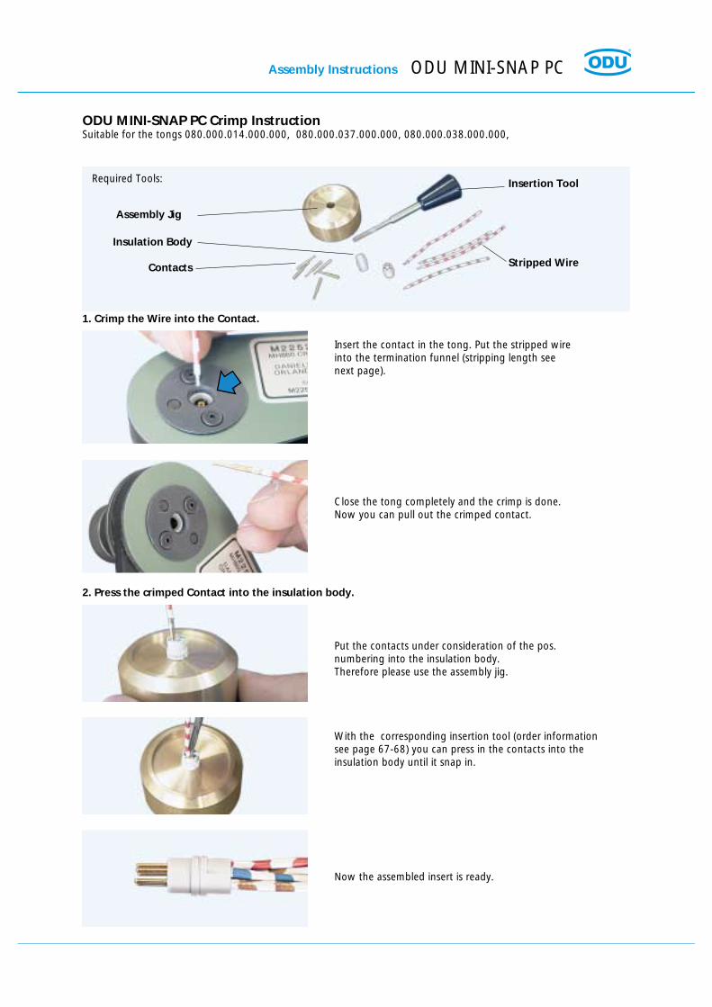
Assembly Instructions ODU MINI-SNAP PC
Insert the contact in the tong. Put the stripped wireinto the termination funnel (stripping length seenext page).
Stripped Wire
Assembly Jig
Insulation Body
Contacts
Insertion Tool
Close the tong completely and the crimp is done.Now you can pull out the crimped contact.
Put the contacts under consideration of the pos.numbering into the insulation body.Therefore please use the assembly jig.
With the corresponding insertion tool (order informationsee page 67-68) you can press in the contacts into theinsulation body until it snap in.
Now the assembled insert is ready.
1. Crimp the Wire into the Contact.
2. Press the crimped Contact into the insulation body.
ODU MINI-SNAP PC Crimp InstructionSuitable for the tongs 080.000.014.000.000, 080.000.037.000.000, 080.000.038.000.000,
Required Tools:

ODU MINI-SNAP PC Assembly Instructions
Cable Preparation:
Contact Solder Termination Crimp TerminationSize Type Ø L A S L A S
The following Table provides recommended guidelines for cable preparation:
Exceptions are noted on special instructions.Right-angle plugs have special instructions.
A
L
S shield
cable
single conductor
insulation
A = Stripping length single conductorL = Stripping length cable jacketS = Stripping length braided shield
Size 1 A & C 0,5 9 2,5 2,5 – – –0,7 9 2,5 2,5 13 3,5 2,50,9 9 2,5 2,5 13 3,5 2,51,3 9 2,5 2,5 13 3,5 2,5
B & D 0,5 13 2,5 2,5 – – –0,7 13 2,5 2,5 17 3,5 2,50,9 13 2,5 2,5 17 3,5 2,51,3 13 2,5 2,5 17 3,5 2,5
Size 2 A & C 0,7 14 2,5 2,5 15 3,5 2,50,9 11 2,5 2,5 15 3,5 2,51,3 11 2,5 2,5 15 3,5 2,51,6 11 2,5 2,5 15 3,5 2,5
B & D 0,7 15 2,5 2,5 19 3,5 2,50,9 15 2,5 2,5 19 3,5 2,51,3 15 2,5 2,5 19 3,5 2,51,6 15 2,5 2,5 19 3,5 2,5
Size 3 A & C 0,7 14 2,5 2,5 18 3,5 2,50,9 14 2,5 2,5 18 3,5 2,51,3 14 2,5 2,5 18 3,5 2,51,6 14 2,5 2,5 24 3,5 2,52,0 20 2,5 2,5 24 3,5 2,5
B & D 0,7 20 2,5 2,5 24 3,5 2,50,9 20 2,5 2,5 24 3,5 2,51,3 20 2,5 2,5 24 3,5 2,51,6 20 2,5 2,5 24 3,5 2,52,0 20 2,5 2,5 24 3,5 2,5
All dimensions in mm Tolerance: + 10 %

ODU Steckverbindungssysteme GmbH & Co. KG, Pregelstr. 11, D-84453 Mühldorf/Inn, Tel. +49/86 31/61 56-0, Fax +49/86 31/61 56 49, www.odu.de Seite 73ODU Steckverbindungssysteme GmbH & Co. KG, Pregelstr. 11, D-84453 Mühldorf/Inn, Tel. +49/86 31/61 56-0, Fax +49/86 31/61 56 49, www.odu.de Seite 73
Assembly Instructions

ODU MINI-SNAP PC Assembly Instructions
Assembly InstructionsFor plugs with plastic inner parts (IP 50) Type B and D
Crimp termination Solder termination
1. Slide back nut, collet and sleeve over the cable.
Screw locking with glue.Recommended glue:Scotch Weld DP 190
2. Strip cable and wire3. Fit wire into the contact barrel and crimp
2. Strip cable and wire3. Pre-tinning of strands recommended
4. Solder each wire to thecorresponding contact
4. insert contacts into insulator, use the insertiontool to push them in
5. Bend cable shield outwards.
6. Slide the collet against the sleeveand clamp the shield between it.
8. Screw back nut on the plug and fasten cabelin the housing. *Now the plug is assembled.
* ODU Spanner-Wrench: see page 63
7. Now you can put the assembled cableinto the plug-housing.
Housing
Crimp insertes
Sleeve Collet Back nutSolder insertes
Part number see page 66
Part number see page 67 and 68
Solder iron
Internal guides

Assembly InstructionsFor plugs with metal inner parts (IP 68) Type A and C
Crimp termination Solder termination
1. Slide Back nut, Collet, Seal Ring and EMI-Ringover the cable.
2. Strip cable and wire3. Fit wire into the contact barrel and crimp
2. Strip cable and wire3. Pre-tinning of strands recommended
4. Solder each wire to thecorresponding contact
4. insert contacts into insulator, use the insertiontool to push them in
5. Bend cable shield outwards.
6. Slide the EMI-Ring against the sleeveand clamp the shield between it.
8. Screw back nut on the plug and fasten cabelin the housing. *Now the plug is assembled.
* ODU Spanner-Wrench: see page 63
7. Now you can put the assembled cableinto the plug-housing.
Housing
Crimp insertesHalf shells
Half shells
Collet
EMI Ring
Seal Ring
Back nut
Solderinsertes
Part number see page 66
Solder iron
Internal guides
Part number see page 67 and 68
Screw locking with glue.Recommended glue:Scotch Weld DP 190
Assembly Instructions ODU MINI-SNAP PC
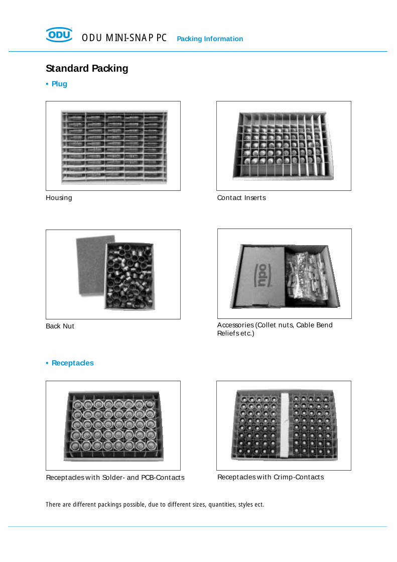
Receptacles with Crimp-ContactsReceptacles with Solder- and PCB-Contacts
Accessories (Collet nuts, Cable Bend Reliefs etc.)
Back Nut
Contact InsertsHousing
There are different packings possible, due to different sizes, quantities, styles ect.
Standard Packing• Plug
• Receptacles
ODU MINI-SNAP PC Packing Information

Gen
eral
Tech
nic
al In
form
atio
ns
GeneralTechnical Informations
ODU MINI-SNAP PC General Technical Information
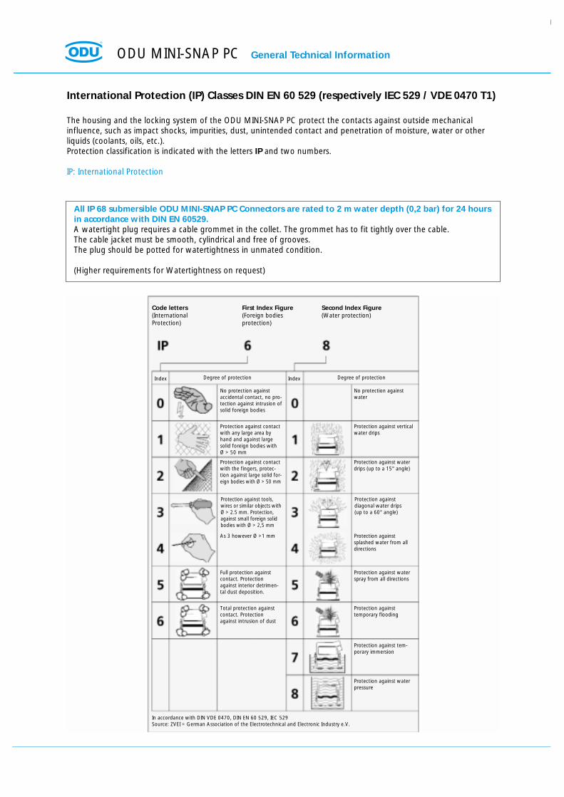
International Protection (IP) Classes DIN EN 60 529 (respectively IEC 529 / VDE 0470 T1)
The housing and the locking system of the ODU MINI-SNAP PC protect the contacts against outside mechanical influence, such as impact shocks, impurities, dust, unintended contact and penetration of moisture, water or otherliquids (coolants, oils, etc.).Protection classification is indicated with the letters IP and two numbers.
IP: International Protection
All IP 68 submersible ODU MINI-SNAP PC Connectors are rated to 2 m water depth (0,2 bar) for 24 hoursin accordance with DIN EN 60529.A watertight plug requires a cable grommet in the collet. The grommet has to fit tightly over the cable. The cable jacket must be smooth, cylindrical and free of grooves.The plug should be potted for watertightness in unmated condition.
(Higher requirements for Watertightness on request)
Index Degree of protection Index Degree of protection
Code letters(International Protection)
First Index Figure(Foreign bodies protection)
Second Index Figure(Water protection)
No protection against accidental contact, no pro-tection against intrusion ofsolid foreign bodies
No protection againstwater
Protection against contactwith any large area byhand and against largesolid foreign bodies withØ > 50 mm
Protection against verticalwater drips
Protection against contactwith the fingers, protec-tion against large solid for-eign bodies with Ø > 50 mm
Protection against waterdrips (up to a 15° angle)
Protection against tools,wires or similar objects withØ > 2.5 mm. Protection,against small foreign solidbodies with Ø > 2,5 mm
Protection against diagonal water drips (up to a 60° angle)
As 3 however Ø >1 mm Protection against splashed water from all directions
Full protection againstcontact. Protectionagainst interior detrimen-tal dust deposition.
Protection against waterspray from all directions
Total protection againstcontact. Protectionagainst intrusion of dust
Protection against temporary flooding
Protection against tem-porary immersion
Protection against waterpressure
In accordance with DIN VDE 0470, DIN EN 60 529, IEC 529Source: ZVEI = German Association of the Electrotechnical and Electronic Industry e.V.

General Technical Information ODU MINI-SNAP PC
Insulation Groups in accordance with DIN VDE 0110 T1, (1989-01)Groups of connectors based on ambient and operating conditions.
Example :
A connector used in a shop environment falls into Group B. (Laboratory environment would fall into Group A).
Insulation Group A0 :
For low power equipment in climate-controlled and dry rooms with only minimal heat rise when subjected to short circuit conditions.
Insulation Group A :
For equipment operated in climate-controlled and dry rooms.
Insulation Group B :
For equipment operated in living quarters, offices, and other commercial environments. Also for clean machine shops,laboratories, test stands, and medical environments.
Insulation Group C :
Equipment primarily operated in industrial, commercial, and agricultural establishments. Non climate-controlledwarehouses, workshops, boiler rooms, and manufacturing floors.
Insulation Group D :
Equipment operated on vehicles subjected to dirt, brake dust, and splash water or snow. Unprotected by housing.
Determination of Nominal Voltage from Test Voltage in accordance with VDE 0627The following explains how to derive the nominal voltage from the test voltage. (For practical purposes nominal voltage, rated voltage, and reference voltage are the same.)
The operating voltage must be less than the nominal voltage. A clear definition can be found in DIN VDE 0110,page 84.
Example :
The selected connector has a test voltage of 1,000 VAC and will be operated in a clean mechanical shop environment(Insulation Group B)According the Table 3 below, the connector has a nominal voltage of 150 VDC. (The example shows both printed inbold.)
Table 3 from DIN VDE 0627
Insulation Groups / Nominal Voltage / Test Voltage
15 12 375 500 750 875 125036 30 500 500 750 1000 150075 60 500 625 875 1000 1500
150 125 625 750 1000 1250 1750300 250 750 875 1250 1750 2250450 380 875 1000 1750 2250 3000600 500 1000 1250 2000 2750 3500800 660 1250 1750 2500 3500 4000900 750 1500 1750 2750 3500 4500
1200 1000 1750 2250 3500 4500 5500
in Volt (DC)
Reference Voltage / Nominal Voltagein Volt
Test Voltagein Volt (AC 50 Hz)
in Volt (AC) A0 A B C D
Insulation Group

Operating voltage acc. to SAE AS 13441-method 3001.1
The values acc. to SAE AS 13441-method 3001.1 comply with MIL-Std. 1344 – method 3001.The chart values results are acc. to IEC 60512. The inserts have been tested in mated condition and the test voltagewas applied to the pin insert.
75% of the measured break-down voltage is the basic for the further calculation. 1/3 of this value is the correspondingoperating voltage.
All tests were performed at standard environment conditions (room temperature) and can be applied up to an altitudeof 2000 m.For any deviations one has to consider the reduction factor acc. to the relevant standards.
Test voltage: Break-down voltage x 0,75Operating voltage: Break-down voltage x 0,75 x 0,33
Caution:
Electrical appliances: for various applications the safety requirements regarding the operating voltage is even moresevere!The relevantdatas in such cases for the operating voltage are the creepage and clearance distances. For any advise how
to chose the proper connector please consult us and indicate the safty standard which your product has to meet.
ODU MINI-SNAP PC General Technical Information

General Technical Information ODU MINI-SNAP PC
Contact blocks (insulation bodies with contacts) are interchangeable between receptacle and plug. As a rule thesocket contact blocks are mounted in the part under power.
ODU offers the following contact termination styles:
Solder
Crimp
PCB
Solder Termination:
The contacts come mounted by the factory. The insulation body and the pre-assembled contacts are called a contactblock.
Termination Styles
Termination Styles for Turned Contacts
Crimp Termination:
A single contact is crimped to a single conductor. Subsequently, the crimped contact is pushed into the insulationbody. Crimp contacts and insulation bodies are shipped separately.
Crimping creates a reliable, corrosion-free and durable connection between the contact and the conductor.
Crimping causes the crimp barrel of the contact and the conductor material to cold flow. It creates a gas-tight connection between contact and conductor.
The ODU MINI-SNAP generally requires the industry-standard 8-point crimp tool .
Printed Circuit Board (PCB) Termination:
PCB pins are used only for receptacles which are mounted directly to the PCB. The contacts are permanently installedin the insulation body.
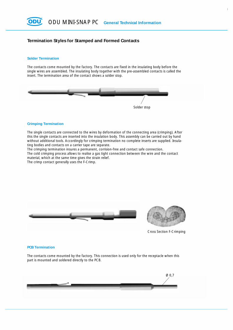
Solder Termination
The contacts come mounted by the factory. The contacts are fixed in the insulating body before thesingle wires are assembled. The insulating body together with the pre-assembled contacts is called theinsert. The termination area of the contact shows a solder stop.
Termination Styles for Stamped and Formed Contacts
Crimping Termination
The single contacts are connected to the wires by deformation of the connecting area (crimping). Afterthis the single contacts are inserted into the insulation body. This assembly can be carried out by handwithout additional tools. Accordingly for crimping termination no complete inserts are supplied. Insula-ting bodies and contacts on a carrier tape are separate.The crimping termination insures a permanent, corrision-free and contact safe connection.The cold crimping process allows to realise a gas tight connection between the wire and the contactmaterial, which at the same time gives the strain relief.The crimp contact generally uses the F-Crimp.
PCB Termination
The contacts come mounted by the factory. This connection is used only for the receptacle when thispart is mounted and soldered directly to the PCB.
Cross Section F-Crimping
Ø 0,7
Solder stop
ODU MINI-SNAP PC General Technical Information

General Technical Information ODU MINI-SNAP PC
Conversion: AWG to Metric
AWG = American Wire Gauge
The AWG system describes the cross section of a wire using a gauge number for every 26 % increase in conductorcross section. With larger wire diameters, the AWG gauge numbers decrease; as the wire sizes increase, the AWG gau-ge numbers decrease.
Most wires are made with stranded conductors. Compared to solid conductors stranded wires offer higher durabili-ty, higher flexibility and better performance under bending and vibration.
Stranded wires are made from wires with smaller gauge sizes (higher AWG gauge number). The AWG gauge numberof the stranded wire is equal to that of a solid conductor of the same size wire. The cross section of the stranded con-ductor is the sum of cross sections of the single conductors.
For example, a AWG-20 stranded wire of 7 AWG-28 conductors has a cross section of 0.563 mm2; an AWG-20 stran-ded wire with 19 AWG-32 conductors has a cross section of 0.616 mm2.
Conversion Table AWG / mm2
(Source: Gore & Associates, Pleinfeld)
Circular ConductorAWG Diameter Cross Section Weight max. Resistance
in mm mm2 kg/km Ω/km10 (1) 0,102 2,59 5,27 47,0 3,4510 (37/26) 1,109 2,75 4,53 43,6 4,1312 (1) 0,0808 2,05 3,31 29,5 5,4512 (19/25) 0,0895 2,25 3,08 28,6 6,1412 (37/28) 0,0858 2,18 2,97 26,3 6,3614 (1) 0,0641 1,63 2,08 18,5 8,7914 (19/27) 0,0670 1,70 1,94 18,0 9,9414 (37/30) 0,0673 1,71 1,87 17,4 10,516 (1) 0,0508 1,29 1,31 11,6 13,9416 (19/29) 0,0551 1,40 1,23 11,0 15,718 (1) 0,0403 1,02 0,82 7,32 22,1818 (19/30) 0,0480 1,22 0,96 8,84 20,420 (1) 0,032 0,813 0,52 4,61 35,120 (7/28) 0,0366 0,93 0,56 5,15 34,120 (19/32) 0,0384 0,98 0,62 5,45 32,022 (1) 0,0252 0,64 0,324 2,89 57,722 (7/30) 0,0288 0,731 0,354 3,24 54,822 (19/34) 0,0307 0,780 0,382 3,41 51,824 (1) 0,0197 0,50 0,196 1,83 91,224 (7/32) 0,023 0,585 0,227 2,08 86,024 (19/36) 0,0252 0,640 0,240 2,16 83,326 (1) 0,157 0,40 0,122 1,14 147,026 (7/34) 0,0189 0,48 0,140 1,29 140,026 (19/38) 0,0192 0,487 0,15 1,40 131,028 (1) 0,0126 0,32 0,08 0,716 231,028 (7/36) 0,015 0,381 0,089 0,813 224,028 (19/40) 0,0151 0,385 0,095 0,931 207,030 (1) 0,0098 0,250 0,0506 0,451 374,030 (7/38) 0,0115 0,293 0,055 0,519 354,030 (19/42) 0,0123 0,312 0,072 0,622 310,032 (1) 0,0080 0,203 0,032 0,289 561,032 (7/40) 0,0094 0,240 0,035 0,340 597,132 (19/44) 0,0100 0,254 0,044 0,356 492,034 (1) 0,0063 0,160 0,0201 0,179 951,034 (7/42) 0,0083 0,211 0,0266 0,113 1491,036 (1) 0,0050 0,127 0,0127 0,072 1519,036 (7/44) 0,0064 0,163 0,0161 0,130 1322,038 (1) 0,0040 0,100 0,0078 0,072 2402,040 (1) 0,0031 0,080 0,0050 0,043 3878,642 (1) 0,0028 0,0700 0,0038 0,028 5964,044 (1) 0,0021 0,054 0,0023 0,018 8660,0

ODU MINI-SNAP PC General Technical Information
Quality Management at ODU
General Technical Information ODU MINI-SNAP PC
Technical Terms and Definitions
Air Gap= Shortest distance between two conductive elements through the air.
Autoclavibility(See page 59)
AWG(See page 83)
Creepage Distance= The distance measured across the surface of a dielectric between two contacts or a contact and a metal part. Thelonger the distance, the lesser the risk of damage or tracking. Minimum creepage distances are specified according tothe operating voltage and the applicable isolation group.
Crimp Area= The part of a crimp barrel at which the crimp connection is achieved by pressure deformation or by reshaping thebarrel around the conductor.
Crimp BarrelA hollow part of a contact which accepts one or more conductors and which may be crimped through the applicationof a crimping tool.
Crimp Connection= The permanent attachment of a contact to a conductor by pressure deformation or by reshaping the crimp barrelaround the conductor so that a good electrical and mechanical connection is established. (See page 82-83)
Connector= A component which terminates conductors for the purpose of providing connection and disconnection to a suitablemating component. Depending on the fastening to a cabinet, panel, rack etc. or a cable, they are classification.
DeliveryDelivery of the connectors usually as components (that means not assembled).Exception: Solder contacts are factory-installed in the insulation body.
Fixed Connector= A connector for attachment to a rigid surface (panel).
Free Connector= A connector for attachment to the free end of a wire or cable. Also called free hanging connector or inline recept-acle.
Insertion Or Withdrawal Force= The force required to fully mate or unmate a set of connectors without the effect of coupling, locking or similardevices. The insertion force is usually greater than the withdrawal force. Also called mating and unmating force.
Insulation Body= Non-conductive part of a connector, to electrically and mechanically separate live parts and to protect against acci-dental touch.
Insulation Group= Classification of connectors according to the operating and working conditions (see page 79 insulation groupsaccording DIN VDE 0110).
Keying= System of projections and grooves on mating connectors which prevent otherwise identical connectors from beingmated. This is useful when several connectors of the same style are used in the same application.

Lower Limit Temperature= The lowest permissible temperature which a connector or a plug-in device is allowed to be operated.
Materials(see page 56).
Mating Cycles= Mechanical operation of connectors and plug-in devices by insertion and withdrawal. One mating cycle comprisesone insertion and one withdrawal operation.
Nominal Single Contact Current Load= Current load, which can load every single contact (see page 54-55).
Nominal VoltageNominal voltage characterizes a component.
Operating Temperature of the ODU MINI-SNAP= Range between upper and lower temperature limits.- 40 °C to + 120 °C (see page 10)
Print Connection(see page 82-83)
Printed Circuit BoardBoards, typically made of epoxy-filled glass fiber fabric, with conductive pattern on one or both sides, or in case ofmultilayer boards, also imbedded inside the board. They feature metallized holes for soldering wire-mounted compo-nents or for the insertion of insertion of resilient or rigid press-in pins or instead, pads for attaching components usingsurface mount technology (SMT).
Reference Current= The current at which a connector can be operated permanently simultaneously through all contacts without rea-ching maximum temperature.
Reference VoltageNormal voltage (VDE 0110) for a connector (see page 81).
Solder Termination(see page 82-83)
Termination techniques= Methods for connecting a wire to an electro-mechanical component, e.g. solderless connection according to IEC60352: respectively such as crimp, press-in etc. or solder connections.
Test Voltage= The voltage the connectors are tested, and are being referred on definite characteristics (see page 81).
Upper Limit Temperature= highest permissible temperature at which a connector or a plug-in device is allowed to operate. This temperatureincludes the self-heating and the ambient temperature. At ODU MINI-SNAP + 120 °C (see page 54-55).
Watertightness(See page 80)
ODU MINI-SNAP PC General Technical Information

General Technical Information ODU MINI-SNAP PC
Wire= Wires may be provided with an insulation cover, an electrical shielding. Cables or conductors may consist of one ormore wires.
Connectors shown in this catalog are designed to operate at high voltages and high frequencies. Care must be takento assure that no person can come in contact with live conductors during installation or operation of the connectors.
ODU assured that at the time of print all information in this catalog was correct. ODU reserves the right to changedesign and performance of any product to meet changing technical developments without prior notice. ODU reservesthe right to discontinue any part in this catalog without prior notice and without obligation to continue productionafter the change.

ODU MINI-SNAP PC For your notes

For yuor notes ODU MINI-SNAP PC

ODU MINI-SNAP PC For your notes

Please open
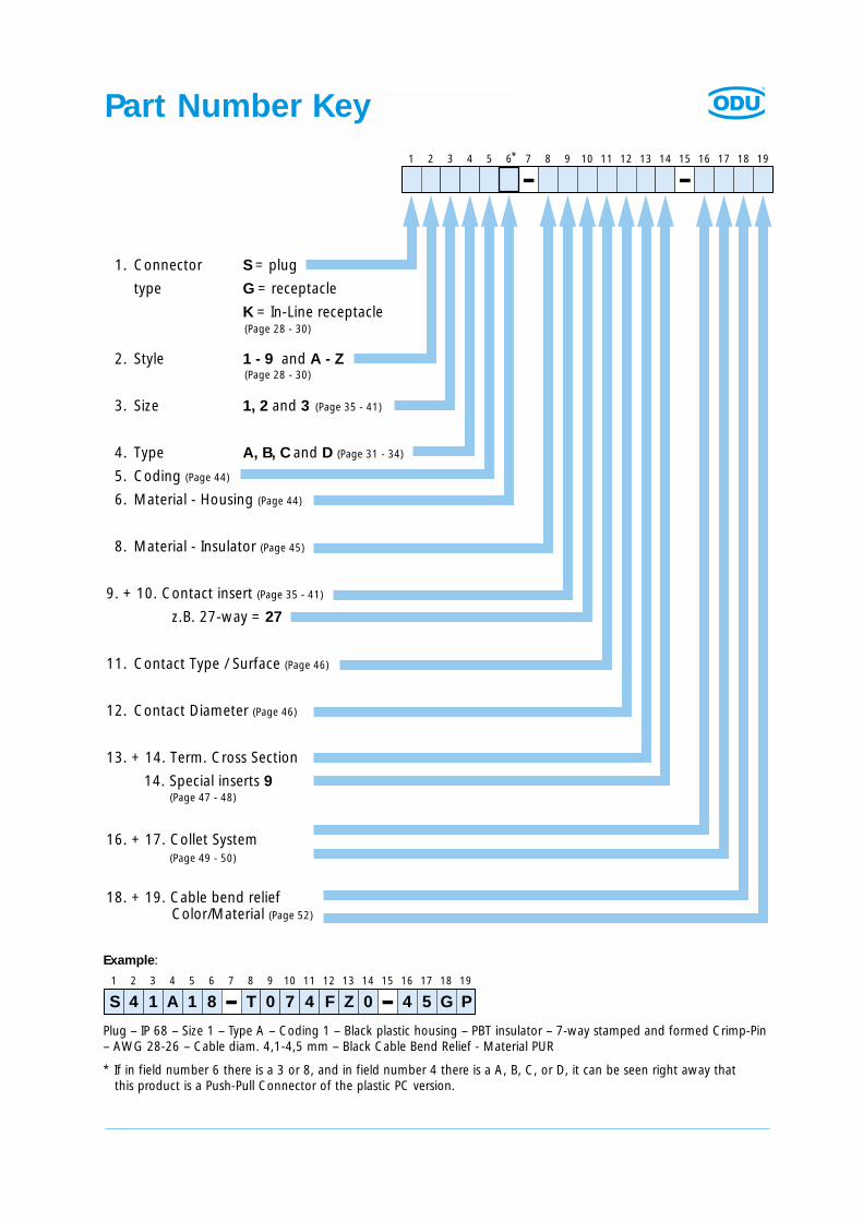
Part Number Key
Example:
Plug – IP 68 – Size 1 – Type A – Coding 1 – Black plastic housing – PBT insulator – 7-way stamped and formed Crimp-Pin– AWG 28-26 – Cable diam. 4,1-4,5 mm – Black Cable Bend Relief - Material PUR
* If in field number 6 there is a 3 or 8, and in field number 4 there is a A, B, C, or D, it can be seen right away thatthis product is a Push-Pull Connector of the plastic PC version.
1 2 3 4 5 6 7 8 9 10 11 12 13 14 15 16 17 18 19*
1. Connector S = plug
type G = receptacle
K = In-Line receptacle
2. Style 1 - 9 and A - Z
3. Size 1, 2 and 3
4. Type A, B, C and D (Page 31 - 34)
5. Coding (Page 44)
6. Material - Housing (Page 44)
8. Material - Insulator (Page 45)
9. + 10. Contact insert (Page 35 - 41)
z.B. 27-way = 27
11. Contact Type / Surface (Page 46)
12. Contact Diameter (Page 46)
13. + 14. Term. Cross Section
14. Special inserts 9
16. + 17. Collet System
18. + 19. Cable bend relief Color/Material (Page 52)
(Page 28 - 30)
(Page 28 - 30)
(Page 35 - 41)
(Page 47 - 48)
(Page 49 - 50)
1 2 3 4 5 6 7 8 9 10 11 12 13 14 15 16 17 18 19
S 4 1 A 1 8 T 0 7 4 F Z 0 4 5 G P

Mühldorf, an idyllic small town with its typical Inn-Salzach architecture.
ODU’s headquarters and factory are located in Mühldorf, at the river Inn,approximately 50 miles east of Munich, at the foothills of the Bavarian Alps.
Phot
o of
City
Müh
ldor
f/In
n
Werr
.05
/04
2 rue René Laennec 51500 Taissy FranceFax: 03 26 85 19 08, Tel : 03 26 82 49 29
E-mail:[email protected] web : www.hvssystem.com