odi guide 11g
TRANSCRIPT

Oracle® Fusion MiddlewareDeveloper’s Guide for Oracle Data Integrator
11g Release 1 (11.1.1)
E12643-04
April 2011

Oracle Fusion Middleware Developer's Guide for Oracle Data Integrator, 11g Release 1 (11.1.1)
E12643-04
Copyright © 2011, Oracle and/or its affiliates. All rights reserved.
Primary Author: Laura Hofman Miquel
This software and related documentation are provided under a license agreement containing restrictions on use and disclosure and are protected by intellectual property laws. Except as expressly permitted in your license agreement or allowed by law, you may not use, copy, reproduce, translate, broadcast, modify, license, transmit, distribute, exhibit, perform, publish, or display any part, in any form, or by any means. Reverse engineering, disassembly, or decompilation of this software, unless required by law for interoperability, is prohibited.
The information contained herein is subject to change without notice and is not warranted to be error-free. If you find any errors, please report them to us in writing.
If this software or related documentation is delivered to the U.S. Government or anyone licensing it on behalf of the U.S. Government, the following notice is applicable:
U.S. GOVERNMENT RIGHTS Programs, software, databases, and related documentation and technical data delivered to U.S. Government customers are "commercial computer software" or "commercial technical data" pursuant to the applicable Federal Acquisition Regulation and agency-specific supplemental regulations. As such, the use, duplication, disclosure, modification, and adaptation shall be subject to the restrictions and license terms set forth in the applicable Government contract, and, to the extent applicable by the terms of the Government contract, the additional rights set forth in FAR 52.227-19, Commercial Computer Software License (December 2007). Oracle USA, Inc., 500 Oracle Parkway, Redwood City, CA 94065.
This software is developed for general use in a variety of information management applications. It is not developed or intended for use in any inherently dangerous applications, including applications which may create a risk of personal injury. If you use this software in dangerous applications, then you shall be responsible to take all appropriate fail-safe, backup, redundancy, and other measures to ensure the safe use of this software. Oracle Corporation and its affiliates disclaim any liability for any damages caused by use of this software in dangerous applications.
Oracle is a registered trademark of Oracle Corporation and/or its affiliates. Other names may be trademarks of their respective owners.
This software and documentation may provide access to or information on content, products, and services from third parties. Oracle Corporation and its affiliates are not responsible for and expressly disclaim all warranties of any kind with respect to third-party content, products, and services. Oracle Corporation and its affiliates will not be responsible for any loss, costs, or damages incurred due to your access to or use of third-party content, products, or services.
iii
Contents
Preface .............................................................................................................................................................. xvii
Audience.................................................................................................................................................... xviiDocumentation Accessibility .................................................................................................................. xviiRelated Documents ................................................................................................................................. xviiiConventions ............................................................................................................................................. xviii
What’s New In Oracle Data Integrator? ......................................................................................... xix
New Features in Oracle Data Integrator 11gR1 PS1 (11.1.1.5) ............................................................ xixNew Features in Oracle Data Integrator 11gR1 (11.1.1.3) ................................................................... xxi
Part I Understanding Oracle Data Integrator
1 Introduction to Oracle Data Integrator
1.1 Introduction to Data Integration with Oracle Data Integrator............................................. 1-11.1.1 Data Integration ................................................................................................................... 1-11.1.2 Oracle Data Integrator......................................................................................................... 1-11.1.3 E-LT........................................................................................................................................ 1-21.2 Oracle Data Integrator Concepts .............................................................................................. 1-31.2.1 Introduction to Declarative Design................................................................................... 1-31.2.2 Introduction to Knowledge Modules ............................................................................... 1-41.2.3 Introduction to Integration Interfaces............................................................................... 1-51.2.3.1 Datastores ...................................................................................................................... 1-61.2.3.2 Declarative Rules .......................................................................................................... 1-61.2.3.3 Data Flow....................................................................................................................... 1-71.3 Typical ODI Integration Projects .............................................................................................. 1-91.3.1 Batch Oriented Integration................................................................................................. 1-91.3.2 Event Oriented Integration.............................................................................................. 1-101.3.3 Service-Oriented Architecture ........................................................................................ 1-101.3.4 Data Quality with ODI..................................................................................................... 1-111.3.5 Managing Environments ................................................................................................. 1-121.4 Oracle Data Integrator Architecture...................................................................................... 1-141.4.1 Repositories ....................................................................................................................... 1-151.4.2 User Interfaces................................................................................................................... 1-161.4.3 Design-time Projects......................................................................................................... 1-171.4.4 Run-Time Agent................................................................................................................ 1-17
iv
2 Oracle Data Integrator QuickStart
2.1 Oracle Data Integrator QuickStart List .................................................................................... 2-1
Part II Administering the Oracle Data Integrator Architecture
3 Administering the Oracle Data Integrator Repositories
3.1 Introduction to Oracle Data Integrator Repositories ............................................................. 3-13.2 Creating Repository Storage Spaces......................................................................................... 3-23.3 Creating the Master Repository ................................................................................................ 3-33.4 Connecting to the Master Repository ...................................................................................... 3-53.5 Creating a Work Repository...................................................................................................... 3-63.6 Connecting to a Work Repository ............................................................................................ 3-73.7 Changing the Work Repository Password.............................................................................. 3-83.8 Advanced Actions for Administering Repositories .............................................................. 3-83.8.1 Attaching and Deleting a Work Repository..................................................................... 3-93.8.2 Erasing a Work Repository.............................................................................................. 3-103.8.3 Renumbering Repositories .............................................................................................. 3-103.8.4 Tuning the Repository ..................................................................................................... 3-11
4 Setting-up the Topology
4.1 Introduction to the Oracle Data Integrator Topology ........................................................... 4-14.1.1 Physical Architecture .......................................................................................................... 4-14.1.2 Contexts................................................................................................................................. 4-24.1.3 Logical Architecture ............................................................................................................ 4-24.1.4 Agents.................................................................................................................................... 4-24.1.5 Languages ............................................................................................................................. 4-44.1.6 Repositories .......................................................................................................................... 4-44.2 Setting Up the Topology ............................................................................................................ 4-44.2.1 Creating a Context ............................................................................................................... 4-54.2.2 Creating a Data Server ........................................................................................................ 4-54.2.2.1 Pre-requisites and Guidelines..................................................................................... 4-54.2.2.2 Creating a Data Server ................................................................................................. 4-64.2.2.3 Creating a Data Server (Advanced Settings) ............................................................ 4-74.2.2.4 Testing a Data Server Connection........................................................................... 4-114.2.3 Creating a Physical Schema ............................................................................................ 4-114.2.4 Creating a Logical Schema .............................................................................................. 4-124.2.5 Creating a Physical Agent ............................................................................................... 4-124.2.6 Creating a Logical Agent ................................................................................................. 4-134.3 Managing Agents..................................................................................................................... 4-134.3.1 Standalone Agent.............................................................................................................. 4-134.3.1.1 Configuring the Standalone Agent ........................................................................ 4-134.3.1.2 Launching a Standalone Agent ............................................................................... 4-154.3.1.3 Stopping an Agent..................................................................................................... 4-164.3.2 Java EE Agent.................................................................................................................... 4-174.3.2.1 Deploying an Agent in a Java EE Application Server (Oracle WebLogic Server) ......
4-17
v
4.3.2.2 Deploying Datasources from Oracle Data Integrator in WLS for an Agent ..... 4-194.3.3 Load Balancing Agents .................................................................................................... 4-204.3.3.1 Delegating Sessions ................................................................................................... 4-204.3.3.2 Agent Unavailable..................................................................................................... 4-214.3.3.3 Setting Up Load Balancing....................................................................................... 4-21
Part III Managing and Reverse-Engineering Metadata
5 Creating and Reverse-Engineering a Model
5.1 Introduction to Models .............................................................................................................. 5-15.1.1 Datastores ............................................................................................................................. 5-15.1.2 Data Integrity ....................................................................................................................... 5-25.1.3 Reverse-engineering............................................................................................................ 5-25.1.4 Changed Data Capture ....................................................................................................... 5-25.2 Creating and Reverse-Engineering a Model ........................................................................... 5-35.2.1 Creating a Model ................................................................................................................. 5-35.2.2 Reverse-engineering a Model ............................................................................................ 5-35.3 Creating and Reverse-Engineering a Datastore ..................................................................... 5-55.3.1 Creating a Datastore............................................................................................................ 5-55.3.2 Reverse-Engineering File Datastores ................................................................................ 5-65.3.2.1 Reverse-Engineering Fixed Files ................................................................................ 5-65.3.2.2 Reverse-Engineering Delimited Files ........................................................................ 5-65.3.2.3 Reverse-Engineering COBOL Files ............................................................................ 5-65.3.3 Adding and Deleting Datastore Columns ...................................................................... 5-75.3.4 Adding and Deleting Constraints and Filters ................................................................. 5-75.3.4.1 Keys ................................................................................................................................ 5-75.3.4.2 References ...................................................................................................................... 5-85.3.4.3 Conditions .................................................................................................................... 5-85.3.4.4 Mandatory Columns ................................................................................................... 5-85.3.4.5 Filter ............................................................................................................................... 5-95.4 Editing and Viewing a Datastore's Data.................................................................................. 5-95.5 Using Partitioning....................................................................................................................... 5-95.5.1 Defining Manually Partitions and Sub-Partitions of Model Datastores................... 5-105.6 Checking Data Quality in a Model........................................................................................ 5-105.6.1 Introduction to Data Integrity......................................................................................... 5-115.6.2 Checking a Constraint...................................................................................................... 5-115.6.3 Perform a Static Check on a Model, Sub-Model or Datastore.................................... 5-115.6.4 Reviewing Erroneous Records........................................................................................ 5-12
6 Working with Common Format Designer
6.1 Introduction to Common Format Designer ............................................................................ 6-16.1.1 What is a Diagram? ............................................................................................................. 6-16.1.2 Why assemble datastores and columns from other models? ........................................ 6-26.1.3 Graphical Synonyms ........................................................................................................... 6-26.2 Using the Diagram...................................................................................................................... 6-26.2.1 Creating a New Diagram.................................................................................................... 6-2
vi
6.2.2 Create Datastores and Columns ........................................................................................ 6-26.2.3 Creating Graphical Synonyms........................................................................................... 6-36.2.4 Creating and Editing Constraints and Filters.................................................................. 6-36.2.5 Printing a Diagram .............................................................................................................. 6-46.3 Generating DDL scripts ............................................................................................................. 6-56.4 Generating Interface IN/OUT .................................................................................................. 6-6
7 Working with Changed Data Capture
7.1 Introduction to Changed Data Capture................................................................................... 7-17.1.1 The Journalizing Components ........................................................................................... 7-17.1.2 Simple vs. Consistent Set Journalizing ............................................................................. 7-27.2 Setting up Journalizing .............................................................................................................. 7-27.2.1 Setting up and Starting Journalizing ................................................................................ 7-27.2.2 Journalizing Infrastructure Details ................................................................................... 7-67.2.3 Journalizing Status............................................................................................................... 7-77.3 Using Changed Data .................................................................................................................. 7-77.3.1 Viewing Changed Data....................................................................................................... 7-87.3.2 Using Changed Data: Simple Journalizing ...................................................................... 7-87.3.3 Using Changed Data: Consistent Set Journalizing ......................................................... 7-97.3.4 Journalizing Tools............................................................................................................. 7-107.3.5 Package Templates for Using Journalizing................................................................... 7-11
8 Working with Data Services
8.1 Introduction to Data Services.................................................................................................... 8-18.2 Setting Up Data Services............................................................................................................ 8-18.2.1 Configuring the Web Services Container......................................................................... 8-28.2.2 Setting up the Data Sources................................................................................................ 8-38.2.3 Configuring the Model ....................................................................................................... 8-38.3 Generating and Deploying Data Services ............................................................................... 8-48.3.1 Generating and Deploying Data Services ........................................................................ 8-58.3.2 Overview of Generated Services ....................................................................................... 8-58.3.3 Testing Data Services .......................................................................................................... 8-6
Part IV Developing Integration Projects
9 Creating an Integration Project
9.1 Introduction to Integration Projects ......................................................................................... 9-19.1.1 Oracle Data Integrator Project Components.................................................................... 9-19.1.1.1 Oracle Data Integrator Project Components ............................................................ 9-19.1.1.2 Global Components...................................................................................................... 9-39.1.2 Project Life Cycle ................................................................................................................. 9-39.2 Creating a New Project .............................................................................................................. 9-39.3 Managing Knowledge Modules ............................................................................................... 9-39.3.1 Knowledge Modules Naming Convention...................................................................... 9-49.3.2 Choosing the Right Knowledge Modules ........................................................................ 9-69.3.3 Importing and Replacing Knowledge Modules.............................................................. 9-7
vii
9.3.4 Encrypting and Decrypting a KM ..................................................................................... 9-89.4 Organizing the Project with Folders ........................................................................................ 9-9
10 Working with Packages
10.1 Introduction to Packages ........................................................................................................ 10-110.1.1 Introduction to Steps ........................................................................................................ 10-110.1.2 Introduction to Creating Packages................................................................................. 10-310.1.3 Introduction to the Package editor................................................................................. 10-310.2 Creating a new Package .......................................................................................................... 10-410.3 Working with Steps ................................................................................................................. 10-410.3.1 Adding a Step.................................................................................................................... 10-410.3.1.1 Executing an Interface............................................................................................... 10-410.3.1.2 Executing a Procedure .............................................................................................. 10-510.3.1.3 Variable Steps............................................................................................................. 10-510.3.1.4 Adding Oracle Data Integrator Tool Steps ............................................................ 10-710.3.1.5 Model, Sub-Models and Datastore Related Steps................................................. 10-710.3.1.6 Checking a Model, Sub-Model or Datastore ........................................................ 10-710.3.1.7 Journalizing a Model or a Datastore....................................................................... 10-810.3.1.8 Reverse-Engineering a Model ................................................................................. 10-810.3.2 Deleting a Step .................................................................................................................. 10-910.3.3 Duplicating a Step............................................................................................................. 10-910.3.4 Running a Step .................................................................................................................. 10-910.3.5 Editing a Step’s Linked Object........................................................................................ 10-910.3.6 Arranging the Steps Layout .......................................................................................... 10-1010.4 Defining the Sequence of Steps............................................................................................ 10-1010.5 Running the Package............................................................................................................. 10-11
11 Working with Integration Interfaces
11.1 Introduction to Integration Interfaces................................................................................... 11-111.1.1 Components of an Integration Interface........................................................................ 11-111.2 Introduction to the Interface Editor ...................................................................................... 11-311.3 Creating an Interface ............................................................................................................... 11-411.3.1 Create a New Interface..................................................................................................... 11-411.3.2 Define the Target Datastore ............................................................................................ 11-511.3.2.1 Permanent Target Datastore .................................................................................... 11-511.3.2.2 Temporary Target Datastore.................................................................................... 11-611.3.2.3 Define the Update Key.............................................................................................. 11-711.3.3 Define the Datasets ........................................................................................................... 11-811.3.4 Define the Source Datastores and Lookups.................................................................. 11-811.3.4.1 Define the Source Datastores ................................................................................... 11-911.3.4.2 Define Lookups........................................................................................................ 11-1011.3.4.3 Define Filters on the Sources.................................................................................. 11-1111.3.4.4 Define Joins between Sources ............................................................................... 11-1211.3.5 Define the Mappings ...................................................................................................... 11-1311.3.6 Define the Interface Flow............................................................................................... 11-1411.3.7 Set up Flow Control and Post-Integration Control.................................................... 11-15
viii
11.3.7.1 Set up Flow Control ................................................................................................ 11-1611.3.7.2 Set up Post-Integration Control............................................................................. 11-1611.3.8 Execute the Integration Interface.................................................................................. 11-1611.4 Using the Quick-Edit Editor................................................................................................. 11-1711.4.1 Adding and Removing a Component ......................................................................... 11-1711.4.1.1 Adding Components............................................................................................... 11-1711.4.1.2 Removing Components .......................................................................................... 11-1911.4.2 Editing a Component ..................................................................................................... 11-1911.4.3 Adding, Removing, and Configuring Datasets.......................................................... 11-2011.4.4 Changing the Target DataStore .................................................................................... 11-2011.4.5 Customizing Tables ........................................................................................................ 11-2111.4.6 Using Keyboard Navigation for Common Tasks....................................................... 11-2111.5 Designing Integration Interfaces: E-LT- and ETL-Style Interfaces ................................. 11-21
12 Working with Procedures, Variables, Sequences, and User Functions
12.1 Working with Procedures....................................................................................................... 12-112.1.1 Introduction to Procedures.............................................................................................. 12-112.1.2 Creating Procedures ......................................................................................................... 12-212.1.2.1 Create a New Procedure........................................................................................... 12-212.1.2.2 Define the Procedure's Options............................................................................... 12-312.1.2.3 Create and Manage the Procedure's Commands.................................................. 12-412.1.3 Using Procedures.............................................................................................................. 12-812.1.3.1 Executing the Procedure........................................................................................... 12-812.1.3.2 Using a Procedure in a Package .............................................................................. 12-912.1.3.3 Generating a Scenario for a Procedure................................................................... 12-912.1.4 Encrypting and Decrypting Procedures........................................................................ 12-912.1.4.1 Encrypting a KM or Procedure................................................................................ 12-912.1.4.2 Decrypting a KM or Procedure ............................................................................. 12-1012.2 Working with Variables ........................................................................................................ 12-1012.2.1 Introduction to Variables............................................................................................... 12-1012.2.2 Creating Variables .......................................................................................................... 12-1112.2.3 Using Variables ............................................................................................................... 12-1212.2.3.1 Using Variables in Packages .................................................................................. 12-1312.2.3.2 Using Variables in Interfaces ................................................................................. 12-1412.2.3.3 Using Variables in Object Properties .................................................................... 12-1512.2.3.4 Using Variables in Procedures............................................................................... 12-1512.2.3.5 Using Variables within Variables.......................................................................... 12-1612.2.3.6 Using Variables in the Resource Name of a Datastore ...................................... 12-1612.2.3.7 Using Variables in a Server URL........................................................................... 12-1712.2.3.8 Using Variables in On Connect/Disconnect Commands.................................. 12-1812.2.3.9 Passing a Variable to a Scenario ............................................................................ 12-1812.2.3.10 Generating a Scenario for a Variable .................................................................... 12-1812.3 Working with Sequences ...................................................................................................... 12-1912.3.1 Introduction to Sequences ............................................................................................. 12-1912.3.2 Creating Sequences......................................................................................................... 12-1912.3.2.1 Creating Standard Sequences ................................................................................ 12-1912.3.2.2 Creating Specific Sequences................................................................................... 12-20
ix
12.3.2.3 Creating Native Sequences .................................................................................... 12-2012.3.3 Using Sequences and Identity Columns ..................................................................... 12-2112.3.3.1 Tips for Using Standard and Specific Sequences................................................ 12-2212.3.3.2 Identity Columns..................................................................................................... 12-2212.4 Working with User Functions.............................................................................................. 12-2312.4.1 Introduction User Functions ......................................................................................... 12-2312.4.2 Creating User Functions ................................................................................................ 12-2312.4.3 Using User Functions ..................................................................................................... 12-24
13 Working with Scenarios
13.1 Introduction to Scenarios........................................................................................................ 13-113.2 Generating a Scenario.............................................................................................................. 13-213.3 Regenerating a Scenario.......................................................................................................... 13-213.4 Generating a Group of Scenarios........................................................................................... 13-313.5 Exporting Scenarios ................................................................................................................. 13-413.6 Importing Scenarios in Production ....................................................................................... 13-413.6.1 Import Scenarios ............................................................................................................... 13-513.6.2 Replace a Scenario ............................................................................................................ 13-513.6.3 Working with a Scenario from a Different Repository ............................................... 13-513.7 Encrypting and Decrypting a Scenario................................................................................. 13-6
14 Working with Load Plans
14.1 Introduction to Load Plans ..................................................................................................... 14-114.1.1 Load Plan Execution Lifecycle ........................................................................................ 14-214.1.2 Differences between Packages, Scenarios, and Load Plans........................................ 14-214.1.3 Load Plan Structure.......................................................................................................... 14-214.1.4 Introduction to the Load Plan Editor............................................................................. 14-414.2 Creating a Load Plan ............................................................................................................... 14-614.2.1 Creating a New Load Plan .............................................................................................. 14-614.2.2 Defining the Load Plan Step Sequence.......................................................................... 14-714.2.2.1 Adding Load Plan Steps ........................................................................................... 14-814.2.2.2 Editing Load Plan Steps.......................................................................................... 14-1114.2.2.3 Deleting a Step ......................................................................................................... 14-1314.2.2.4 Duplicating a Step ................................................................................................... 14-1314.2.3 Working with Variables in Load Plans........................................................................ 14-1314.2.3.1 Declaring Load Plan Variables .............................................................................. 14-1414.2.3.2 Setting Variable Values in a Step........................................................................... 14-1414.2.4 Handling Load Plan Exceptions and Restartability................................................... 14-1514.2.4.1 Defining Exceptions Flows..................................................................................... 14-1514.2.4.2 Using Exception Handling ..................................................................................... 14-1614.2.4.3 Defining the Restart Behavior................................................................................ 14-1714.3 Running Load Plans .............................................................................................................. 14-1714.4 Using Load Plans in Production .......................................................................................... 14-1814.4.1 Running Load Plans in Production.............................................................................. 14-1814.4.2 Scheduling Load Plans................................................................................................... 14-1814.4.3 Exporting, Importing and Versioning Load Plans..................................................... 14-18
x
14.4.3.1 Exporting Load Plans.............................................................................................. 14-1814.4.3.2 Importing Load Plans ............................................................................................. 14-1914.4.3.3 Versioning Load Plans............................................................................................ 14-19
15 Working with Web Services in Oracle Data Integrator
15.1 Introduction to Web Services in Oracle Data Integrator.................................................... 15-115.2 Data Services............................................................................................................................. 15-215.3 Oracle Data Integrator Run-Time Services........................................................................... 15-315.4 Invoking Third-Party Web Services ...................................................................................... 15-315.4.1 Introduction to Web Service Invocation........................................................................ 15-315.4.2 Using the OdiInvokeWebService Tool .......................................................................... 15-315.4.3 Web Service Invocation in Integration Flows............................................................... 15-7
16 Working with Oracle Data Quality Products
16.1 Introduction to Oracle Data Quality Products .................................................................... 16-116.2 The Data Quality Process........................................................................................................ 16-116.2.1 Create a Quality Input File .............................................................................................. 16-216.2.2 Create an Entity................................................................................................................. 16-216.2.2.1 Step 1: Validate Loader Connections...................................................................... 16-216.2.2.2 Step 2: Create Entity and Import Data ................................................................... 16-316.2.2.3 Step 3: Verify Entity .................................................................................................. 16-416.2.3 Create a Profiling Project ................................................................................................. 16-516.2.4 Create a Oracle Data Quality Project ............................................................................. 16-516.2.5 Export the Data Quality Project...................................................................................... 16-516.2.6 Reverse-engineer the Entities.......................................................................................... 16-816.2.7 Use Oracle Data Quality Input and Output Files in Interfaces.................................. 16-916.2.8 Run this Quality Project from Oracle Data Integrator ............................................... 16-916.2.9 Sequence the Process in a Package................................................................................. 16-9
Part V Managing Integration Projects
17 Organizing and Documenting your Work
17.1 Organizing Projects with Folders .......................................................................................... 17-117.1.1 Creating a New Folder..................................................................................................... 17-117.1.2 Arranging Project Folders ............................................................................................... 17-217.2 Organizing Models with Folders........................................................................................... 17-217.2.1 Creating a New Model Folder ........................................................................................ 17-217.2.2 Arranging Model Folders ................................................................................................ 17-217.2.3 Creating and Organizing Sub-Models........................................................................... 17-217.3 Using Cross-References........................................................................................................... 17-417.3.1 Browsing Cross-References ............................................................................................. 17-417.3.2 Resolving Missing References......................................................................................... 17-517.4 Using Markers and Memos .................................................................................................... 17-517.4.1 Markers .............................................................................................................................. 17-617.4.2 Memos ................................................................................................................................ 17-717.5 Handling Concurrent Changes.............................................................................................. 17-7
xi
17.5.1 Concurrent Editing Check............................................................................................... 17-717.5.2 Object Locking................................................................................................................... 17-817.6 Creating PDF Reports.............................................................................................................. 17-917.6.1 Generating a Topology Report ....................................................................................... 17-917.6.2 Generating a Report for the Version Comparison Results ......................................... 17-917.6.3 Generating a Report for an Oracle Data Integrator Object ......................................... 17-917.6.4 Generating a Diagram Report....................................................................................... 17-10
18 Working with Version Management
18.1 Working with Object Flags ..................................................................................................... 18-118.2 Working with Versions ........................................................................................................... 18-218.3 Working with the Version Comparison Tool ...................................................................... 18-418.3.1 Viewing the Differences between two Versions .......................................................... 18-418.3.2 Using Comparison Filters................................................................................................ 18-518.3.3 Generating and Printing a Report of your Comparison Results ............................... 18-618.4 Working with Solutions .......................................................................................................... 18-618.4.1 Working with Elements in a Solution............................................................................ 18-718.4.2 Synchronizing Solutions .................................................................................................. 18-718.4.3 Restoring and Checking in a Solution ........................................................................... 18-818.4.4 Importing and Exporting Solutions ............................................................................... 18-8
19 Exporting/Importing
19.1 Import and Export Concepts .................................................................................................. 19-119.1.1 Internal Identifiers (IDs) .................................................................................................. 19-119.1.2 Relationships between Objects ....................................................................................... 19-219.1.3 Import Modes.................................................................................................................... 19-319.1.4 Tips for Import/Export.................................................................................................... 19-519.2 Exporting and Importing Objects .......................................................................................... 19-619.2.1 Exporting one ODI Object ............................................................................................... 19-719.2.2 Export Multiple ODI Objects .......................................................................................... 19-819.2.3 Importing Objects ............................................................................................................. 19-819.3 Repository-Level Export/Import ........................................................................................ 19-1019.3.1 Exporting and Importing the Master Repository....................................................... 19-1019.3.2 Export/Import the Topology and Security Settings.................................................. 19-1219.3.3 Exporting and Importing a Work Repository ............................................................ 19-1319.4 Exporting the Technical Environment ................................................................................ 19-14
Part VI Running and Monitoring Integration Processes
20 Running Integration Processes
20.1 Understanding ODI Executions............................................................................................. 20-120.2 Executing Interfaces, Procedures, Packages and Model Operations ............................... 20-320.3 Executing a Scenario................................................................................................................ 20-320.3.1 Executing a Scenario from ODI Studio.......................................................................... 20-320.3.2 Executing a Scenario from a Command Line ............................................................... 20-420.4 Restarting a Session ................................................................................................................. 20-6
xii
20.4.1 Restarting a Session from ODI Studio ........................................................................... 20-720.4.2 Restarting a Session from a Command Line................................................................. 20-720.5 Stopping a Session ................................................................................................................... 20-820.5.1 Stopping a Session From ODI Studio ............................................................................ 20-920.5.2 Stopping a Session From a Command Line.................................................................. 20-920.6 Executing a Load Plan........................................................................................................... 20-1020.6.1 Executing a Load Plan from ODI Studio..................................................................... 20-1020.6.2 Executing a Load Plan from a Command Line .......................................................... 20-1020.7 Restarting a Load Plan Run.................................................................................................. 20-1220.7.1 Restarting a Load Plan from ODI Studio .................................................................... 20-1220.7.2 Restarting a Load Plan from a Command Line.......................................................... 20-1220.8 Stopping a Load Plan Run.................................................................................................... 20-1320.8.1 Stopping a Load Plan from ODI Studio ...................................................................... 20-1420.8.2 Stopping a Load Plan Run from a Command Line ................................................... 20-1420.9 Scheduling Scenarios and Load Plans ................................................................................ 20-1520.9.1 Scheduling a Scenario or a Load Plan with the Built-in Scheduler ......................... 20-1520.9.1.1 Scheduling a Scenario or a Load Plan .................................................................. 20-1520.9.1.2 Updating an Agent’s Schedule .............................................................................. 20-1720.9.1.3 Displaying the Schedule ......................................................................................... 20-1720.9.2 Scheduling a Scenario or a Load Plan with an External Scheduler......................... 20-1820.10 Simulating an Execution ....................................................................................................... 20-1920.11 Managing Executions Using Web Services ........................................................................ 20-1920.11.1 Introduction to Run-Time Web Services ..................................................................... 20-1920.11.2 Executing a Scenario Using a Web Service ................................................................. 20-2020.11.3 Monitoring a Session Status Using a Web Service..................................................... 20-2120.11.4 Restarting a Session Using a Web Service................................................................... 20-2120.11.5 Executing a Load Plan Using a Web Service .............................................................. 20-2220.11.6 Stopping a Load Plan Run Using a Web Service ....................................................... 20-2320.11.7 Restarting a Load Plan Instance Using a Web Service .............................................. 20-2420.11.8 Monitoring a Load Plan Run Status Using a Web Service ....................................... 20-2420.11.9 Listing Contexts Using a Web Service ......................................................................... 20-2520.11.10 Listing Scenarios Using a Web Service........................................................................ 20-2520.11.11 Accessing the Web Service from a Command Line................................................... 20-2520.11.12 Using the Run-Time Web Services with External Authentication ......................... 20-2720.11.13 Using WS-Addressing.................................................................................................... 20-2820.11.14 Using Asynchronous Web Services with Callback................................................... 20-29
21 Monitoring Integration Processes
21.1 Introduction to Monitoring .................................................................................................... 21-121.1.1 Introduction to Operator Navigator .............................................................................. 21-121.1.2 Scenarios............................................................................................................................. 21-221.1.3 Sessions .............................................................................................................................. 21-221.1.4 Load Plans.......................................................................................................................... 21-321.1.5 Load Plan Executions ....................................................................................................... 21-321.1.6 Schedules............................................................................................................................ 21-321.1.7 Log ...................................................................................................................................... 21-321.1.8 Status .................................................................................................................................. 21-3
xiii
21.2 Monitoring Executions Results .............................................................................................. 21-421.2.1 Monitoring Sessions ......................................................................................................... 21-421.2.2 Monitoring Load Plan Runs............................................................................................ 21-521.2.3 Handling Failed Sessions................................................................................................. 21-521.2.4 Reviewing Successful Sessions ....................................................................................... 21-621.2.5 Handling Failed Load Plans............................................................................................ 21-721.2.6 Reviewing Successful Load Plans .................................................................................. 21-721.3 Managing your Executions..................................................................................................... 21-721.3.1 Managing Sessions ........................................................................................................... 21-721.3.1.1 Cleaning Stale Sessions............................................................................................. 21-821.3.2 Managing Load Plan Executions .................................................................................... 21-821.3.3 Managing the Log ............................................................................................................ 21-821.3.3.1 Filtering Sessions ....................................................................................................... 21-821.3.3.2 Purging the Log ......................................................................................................... 21-921.3.3.3 Organizing the Log with Session Folders ............................................................ 21-1021.3.3.4 Exporting and Importing Log Data ...................................................................... 21-1121.3.4 Managing Scenarios and Load Plans ........................................................................... 21-1221.3.4.1 Load Plan and Scenario Folders ............................................................................ 21-1321.3.4.2 Importing Load Plans, Scenarios, and Solutions in Production ....................... 21-1321.3.5 Managing Schedules ...................................................................................................... 21-13
22 Working with Oracle Data Integrator Console
22.1 Introduction to Oracle Data Integrator Console.................................................................. 22-122.1.1 Introduction to Oracle Data Integrator Console .......................................................... 22-122.1.2 Oracle Data Integrator Console Interface...................................................................... 22-222.2 Using Oracle Data Integrator Console.................................................................................. 22-322.2.1 Connecting to Oracle Data Integrator Console ............................................................ 22-322.2.2 Generic User Operations.................................................................................................. 22-422.2.3 Managing Scenarios and Sessions.................................................................................. 22-522.2.4 Managing Load Plans....................................................................................................... 22-722.2.5 Purging the Log................................................................................................................. 22-922.2.6 Using Data Lineage and Flow Map ............................................................................. 22-1022.2.7 Performing Administrative Operations ...................................................................... 22-12
Part VII Managing the Security Settings
23 Managing the Security in Oracle Data Integrator
23.1 Introduction to Oracle Data Integrator Security ................................................................. 23-123.1.1 Objects, Instances and Methods ..................................................................................... 23-123.1.2 Profiles................................................................................................................................ 23-223.1.3 Users ................................................................................................................................... 23-323.2 Setting up a Security Policy.................................................................................................... 23-423.2.1 Security Policy Approach ................................................................................................ 23-423.2.2 Managing Profiles............................................................................................................. 23-523.2.2.1 Creating a New Profile ............................................................................................. 23-523.2.2.2 Duplicating a Profile ................................................................................................. 23-5
xiv
23.2.2.3 Deleting a Profile ....................................................................................................... 23-523.2.3 Managing Users ................................................................................................................ 23-523.2.3.1 Creating a New User................................................................................................. 23-523.2.3.2 Assigning a Profile to a User.................................................................................... 23-623.2.3.3 Removing a Profile from a User .............................................................................. 23-623.2.3.4 Deleting a User........................................................................................................... 23-623.2.4 Managing Privileges......................................................................................................... 23-723.2.4.1 Granting a Profile Method or User Method .......................................................... 23-723.2.4.2 Revoking a Profile Method or User Method ......................................................... 23-723.2.4.3 Granting an Authorization by Object Instance ..................................................... 23-723.2.4.4 Revoking an Authorization by Object Instance .................................................... 23-823.2.4.5 Cleaning up Unused Authorizations...................................................................... 23-823.3 Advanced Security................................................................................................................... 23-923.3.1 Setting Up External Password Storage .......................................................................... 23-923.3.1.1 Setting the Password Storage................................................................................... 23-923.3.1.2 Switching the Password Storage ........................................................................... 23-1023.3.1.3 Recovering the Password Storage......................................................................... 23-1023.3.2 Setting Up External Authentication ............................................................................. 23-1123.3.2.1 Configuring ODI Components for External Authentication ............................ 23-1123.3.2.2 Setting the Authentication Mode .......................................................................... 23-1223.3.2.3 Switching the Authentication Mode..................................................................... 23-1223.3.3 Enforcing Password Policies ......................................................................................... 23-14
A Oracle Data Integrator Tools Reference
A.1 Using the Oracle Data Integrator Tools .................................................................................. A-1A.1.1 Using a Tool in a Package.................................................................................................. A-1A.1.2 Using a Tool in a Knowledge Module or a Procedure Command .............................. A-2A.1.3 Using a Tool from a Command Line ............................................................................... A-2A.2 Using Open Tools ...................................................................................................................... A-2A.2.1 Installing and Declaring an Open Tool ........................................................................... A-3A.2.1.1 Installing an Open Tool .............................................................................................. A-3A.2.1.2 Declaring a New Open Tool ...................................................................................... A-3A.2.2 Using Open Tools in a Package or Procedure ................................................................ A-4A.3 Developing Open Tools ............................................................................................................ A-4A.3.1 Classes .................................................................................................................................. A-4A.3.2 Developing a New Open Tool .......................................................................................... A-4A.3.2.1 Implementing the Class .............................................................................................. A-5A.3.3 Open Tools at Run Time .................................................................................................... A-7A.4 ODI Tools per Category ............................................................................................................ A-8A.4.1 Metadata............................................................................................................................... A-8A.4.2 Oracle Data Integrator Objects.......................................................................................... A-8A.4.3 Utilities ................................................................................................................................. A-8A.4.4 Internet Related Tasks........................................................................................................ A-9A.4.5 Files ....................................................................................................................................... A-9A.4.6 SAP........................................................................................................................................ A-9A.4.7 XML ...................................................................................................................................... A-9A.4.8 Event Detection ................................................................................................................. A-10
xv
A.4.9 Changed Data Capture .................................................................................................... A-10A.5 Alphabetic List of ODI Tools.................................................................................................. A-10A.5.1 OdiAnt................................................................................................................................ A-12A.5.2 OdiBeep.............................................................................................................................. A-13A.5.3 OdiDataQuality................................................................................................................. A-13A.5.4 OdiDeleteScen ................................................................................................................... A-14A.5.5 OdiExportAllScen ............................................................................................................. A-14A.5.6 OdiExportEnvironmentInformation.............................................................................. A-16A.5.7 OdiExportLog.................................................................................................................... A-17A.5.8 OdiExportMaster .............................................................................................................. A-18A.5.9 OdiExportObject ............................................................................................................... A-19A.5.10 OdiExportScen .................................................................................................................. A-21A.5.11 OdiExportWork................................................................................................................. A-22A.5.12 OdiFileAppend ................................................................................................................. A-23A.5.13 OdiFileCopy ...................................................................................................................... A-24A.5.14 OdiFileDelete..................................................................................................................... A-26A.5.15 OdiFileMove...................................................................................................................... A-28A.5.16 OdiFileWait........................................................................................................................ A-29A.5.17 OdiFtpGet .......................................................................................................................... A-32A.5.18 OdiFtpPut .......................................................................................................................... A-33A.5.19 OdiGenerateAllScen......................................................................................................... A-35A.5.20 OdiImportObject ............................................................................................................... A-36A.5.21 OdiImportScen .................................................................................................................. A-37A.5.22 OdiInvokeWebService ..................................................................................................... A-37A.5.23 OdiKillAgent ..................................................................................................................... A-40A.5.24 OdiMkDir........................................................................................................................... A-41A.5.25 OdiOSCommand .............................................................................................................. A-41A.5.26 OdiOutFile ......................................................................................................................... A-42A.5.27 OdiPingAgent ................................................................................................................... A-43A.5.28 OdiPurgeLog ..................................................................................................................... A-44A.5.29 OdiReadMail ..................................................................................................................... A-46A.5.30 OdiRefreshJournalCount ................................................................................................. A-48A.5.31 OdiReinitializeSeq ............................................................................................................ A-49A.5.32 OdiReverseGetMetaData................................................................................................. A-50A.5.33 OdiReverseResetTable ..................................................................................................... A-51A.5.34 OdiReverseSetMetaData.................................................................................................. A-51A.5.35 OdiRetrieveJournalData .................................................................................................. A-51A.5.36 OdiSAPALEClient and OdiSAPALEClient3 ................................................................ A-53A.5.37 OdiSAPALEServer and OdiSAPALEServer3 ............................................................... A-54A.5.38 OdiScpGet .......................................................................................................................... A-56A.5.39 OdiScpPut .......................................................................................................................... A-58A.5.40 OdiSendMail...................................................................................................................... A-60A.5.41 OdiSftpGet ......................................................................................................................... A-62A.5.42 OdiSftpPut ......................................................................................................................... A-64A.5.43 OdiSleep ............................................................................................................................. A-66A.5.44 OdiSqlUnload.................................................................................................................... A-66A.5.45 OdiStartLoadPlan ............................................................................................................. A-68
xvi
A.5.46 OdiStartScen ...................................................................................................................... A-69A.5.47 OdiUnZip........................................................................................................................... A-71A.5.48 OdiUpdateAgentSchedule .............................................................................................. A-72A.5.49 OdiWaitForChildSession ................................................................................................. A-72A.5.50 OdiWaitForData................................................................................................................ A-74A.5.51 OdiWaitForLogData......................................................................................................... A-77A.5.52 OdiWaitForTable .............................................................................................................. A-80A.5.53 OdiXMLConcat ................................................................................................................. A-81A.5.54 OdiXMLSplit ..................................................................................................................... A-83A.5.55 OdiZip ................................................................................................................................ A-85
B User Parameters
xvii
Preface
This manual describes how to use Oracle Data Integrator.
This preface contains the following topics:.
■ Audience
■ Documentation Accessibility
■ Related Documents
■ Conventions
AudienceThis document is intended for developers and administrators who want to use Oracle Data Integrator as a development tool for their integration processes. This guide explains how to work with the graphical components that make up the Oracle Data Integrator graphical user interface. It guides you through common tasks and worked examples of development in Oracle Data Integrator. It includes conceptual and background information on the features and functionalities of Oracle Data Integrator.
Documentation AccessibilityOur goal is to make Oracle products, services, and supporting documentation accessible to all users, including users that are disabled. To that end, our documentation includes features that make information available to users of assistive technology. This documentation is available in HTML format, and contains markup to facilitate access by the disabled community. Accessibility standards will continue to evolve over time, and Oracle is actively engaged with other market-leading technology vendors to address technical obstacles so that our documentation can be accessible to all of our customers. For more information, visit the Oracle Accessibility Program Web site at http://www.oracle.com/accessibility/.
Accessibility of Code Examples in DocumentationScreen readers may not always correctly read the code examples in this document. The conventions for writing code require that closing braces should appear on an otherwise empty line; however, some screen readers may not always read a line of text that consists solely of a bracket or brace.
xviii
Accessibility of Links to External Web Sites in DocumentationThis documentation may contain links to Web sites of other companies or organizations that Oracle does not own or control. Oracle neither evaluates nor makes any representations regarding the accessibility of these Web sites.
Access to Oracle SupportOracle customers have access to electronic support through My Oracle Support. For information, visit http://www.oracle.com/support/contact.html or visit http://www.oracle.com/accessibility/support.html if you are hearing impaired.
Related DocumentsFor more information, see the following Oracle resources:
■ Oracle Fusion Middleware Getting Started with Oracle Data Integrator
■ Oracle Fusion Middleware Installation Guide for Oracle Data Integrator
■ Oracle Fusion Middleware Upgrade Guide for Oracle Data Integrator
■ Oracle Fusion Middleware Developer's Guide for Oracle Data Integrator
■ Oracle Fusion Middleware Connectivity and Modules Guide for Oracle Data Integrator
■ Oracle Fusion Middleware Application Adapters Guide for Oracle Data Integrator
■ Oracle Fusion Middleware Knowledge Module Developer's Guide for Oracle Data Integrator
■ Oracle Data Integrator 11g Online Help
■ Oracle Data Integrator 11g Release Notes, included with your Oracle Data Integrator 11g installation, and on Oracle Technology Network
ConventionsThe following text conventions are used in this document:
Convention Meaning
boldface Boldface type indicates graphical user interface elements associated with an action, or terms defined in text or the glossary.
italic Italic type indicates book titles, emphasis, or placeholder variables for which you supply particular values.
monospace Monospace type indicates commands within a paragraph, URLs, code in examples, text that appears on the screen, or text that you enter.
xix
What’s New In Oracle Data Integrator?
This document describes the new and enhanced features introduced with Oracle Data Integrator 11g Release 1 (11.1.1).
This chapter includes the following sections:
■ New Features in Oracle Data Integrator 11gR1 PS1 (11.1.1.5)
■ New Features in Oracle Data Integrator 11gR1 (11.1.1.3)
New Features in Oracle Data Integrator 11gR1 PS1 (11.1.1.5)The first Oracle Data Integrator 11gR1 Patch Set introduces the following enhancements:
■ Load Plans
■ OBIEE Lineage
■ Commands on Connect/Disconnect
■ Complex File Technology
■ Groovy Technology
■ Web Services Enhancements
■ Built-in Technology Additions and Updates
■ Support for Technologies with Ordered and Non-Ordered Join Syntax
■ New Method for Setting Task Names
■ Shared Library for WLS Agent
■ Performance Optimization
Load PlansLoad Plans are new objects introduced in this release to organize at a high level the execution of packages and scenarios. Load Plans provide features for parallel, sequential, and conditional scenario execution, restartability, and exception handling. Load Plans can be created and modified in production environments.
OBIEE LineageOracle Business Intelligence Enterprise Edition (OBIEE) users need to know the origin of the data displayed on their reports. When this data is loaded from source systems into the data warehouse using Oracle Data Integrator, it is possible to use the Oracle Data Integrator Lineage for Oracle Business Intelligence feature to consolidate ODI
xx
metadata with OBIEE and expose this metadata in a report-to-source data lineage dashboard in OBIEE.
Commands on Connect/DisconnectIt is possible to define for a data server commands that will be automatically executed when connections to this data server are created or closed by ODI components or by a session.
Complex File TechnologyComplex file formats (multiple record files) can now be integrated using the new Complex File technology. This technology leverages a new built-in driver that converts transparently complex file formats into a relational structure using a Native Schema (nXSD) description file.
Groovy TechnologyGroovy is added to the list of scripting engines supported by Oracle Data Integrator for use in knowledge modules and procedures.
Web Services EnhancementsWeb service support in Oracle Data Integrator has been enhanced with the following features:
■ Support for Container Based Authentication: When external authentication and container based authentication with Oracle Platform Security Services (OPSS) are configured, authentication can be passed to the ODI Run-Time Web Services using HTTP basic authentication, WS-Security headers, SAML tokens and so forth and not in the SOAP request.
■ Support for Asynchronous calls and Callback: A scenario or session can be started using the Run-Time Web Services on a one-way operation. When the session completes, the result of the execution can trigger an operation on a callback address. This pattern can be used for handling long running sessions started, for example, from Oracle BPEL.
■ Full SOAP edition for outbound web services calls: The OdiInvokeWebService tool now supports full-formed SOAP messages including the SOAP header and body.
Built-in Technology Additions and UpdatesThe following technologies used in Oracle Data Integrator have been added and updated:
■ Embedded HSQL engine is upgraded to version 2.0. This embedded engine is used for the Memory Engine as well as the XML and LDAP Drivers' built-in storage
■ Jython BSF engine is updated to version 2.1
■ JAX-WS/JRF is now used as a standard stack for web service calls and processing. Axis is no longer used
Support for Technologies with Ordered and Non-Ordered Join SyntaxTechnologies can now support both the ordered or non-ordered (database-specific) syntax for joins. The Oracle DB technology was modified to support both join syntaxes.
xxi
New Method for Setting Task NamesA new setTaskName method is available to update at run-time the name of a task.
Shared Library for WLS AgentA new template called Oracle Data Integrator - Agent Libraries includes libraries shared by all the deployed JEE agent in a domain, and must be deployed before the Oracle Data Integrator - Agent default template or a generate template.
Performance OptimizationThe following optimizations have been made in the design-time and run-time components to improve their performance:
■ Long texts storage modified to use CLOBs
■ Agent-Repository network communications reduced at run-time
■ Agent JDBC to JDBC loading mechanism reviewed and optimized
New Features in Oracle Data Integrator 11gR1 (11.1.1.3)This first release of Oracle Data Integrator introduces a large number of new features, grouped in this section by release themes.
This section includes the following topics:
■ Release Themes. This section provides the primary themes of this release and associated features.
■ New Features. This section provides a complete list of the new features for this release.
Release ThemesWhile the new features of Oracle Data Integrator for this release cover a number of different areas, the most important changes for new and existing customers are:
■ New Architectures Supported for Enterprise-Scale Deployment Options
■ Core Design-Time Features for Enhanced Productivity and Performance
■ Standard JDeveloper-Based IDE: Oracle Data Integrator Studio
■ Developer Usability and Productivity Enhancements
■ New Features for Administration
■ Enhanced Diagnostic Features and Capabilities
■ Technologies and Knowledge Modules Enhancements
New Architectures Supported for Enterprise-Scale Deployment OptionsOracle Data Integrator now provides several deployment options for lightweight standalone deployments and enhanced architectures for deployments based on cluster-able and fault tolerant application server frameworks. Features in this area include:
■ Standalone Agent deployment when agents should be deployed on the same hardware where database software is running
■ Java EE Agent when agents are used in a clustered Java EE configuration
xxii
■ External Password Storage and External Authentication and SSO for hardening security and support centralized authentication
■ Repository Connection Retry, OPMN Integration and Support for WLS Clustering for high-availability
■ Java EE Agent Template Generation, Pre-Packaged WebLogic Server Templates for Java EE Components and Automatic Datasource Creation for WebLogic Server
Core Design-Time Features for Enhanced Productivity and PerformanceOracle Data Integrator now provides a set of core features for increasing development productivity and the performance of the integration flows. Features in this area include:
■ Datasets and Set-Based Operators
■ Support for Natural Joins
■ Partitioning
■ Lookups
■ Derived Select for Temporary Interfaces
■ Automatic Temporary Index Management
■ Support for Native Sequences
Standard JDeveloper-Based IDE: Oracle Data Integrator StudioThe Oracle Data Integrator User Interface now uses the JDeveloper-based integrated development environment (IDE), and is renamed Oracle Data Integrator Studio.
The user interface has been entirely redesigned in this release to improve developer productivity and make advanced features more accessible. This new IDE provides the following key features:
■ New Navigator Organization
■ New Look and Feel
■ Redesigned Editors
■ Improved User Assistance
Developer Usability and Productivity EnhancementsIn addition to the entire redesign of the development interface, features have been added to improve the developer’s experience and productivity while working in Oracle Data Integrator. Features in this area include:
■ New Interface Editor
■ Quick-Edit to edit interface in a tabular view
■ Auto fixing errors from the interface editor
■ Scenario Naming Convention
■ Oracle Data Integrator Java API to programmatically manage design and run-time operations.
New Features for AdministrationFeatures have been added to improve manageability of the Oracle Data Integrator components and sessions. Features in this area include:
xxiii
■ New Oracle Data Integrator Console
■ Oracle Fusion Middleware Control Console Integration
■ Stale Session Detection and Management
■ Kill Sessions Immediate
■ Import Report and Repository Corruption Prevention
Enhanced Diagnostic Features and CapabilitiesOracle Data Integrator has been improved with features to facilitate problems troubleshooting and fixing. Features in this area include:
■ Enhanced Error Messages
■ Enhanced Notifications and Logging
■ Code Simulation
■ Row-By-Row KMs for Debugging.
Technologies and Knowledge Modules EnhancementsNew technologies and knowledge modules planned for this release have been continuously delivered during the 10g lifecycle patch sets. In addition, existing knowledge modules and technologies have been enhanced to support new core product features and diagnostics.
Features added in 10g Release 3 patch sets include:
■ Oracle GoldenGate Knowledge Modules
■ Oracle E-Business Suite Knowledge Modules
■ Oracle OLAP Knowledge Modules
■ Oracle PeopleSoft Knowledge Modules
■ Oracle Siebel Knowledge Modules
■ JDE EnterpriseOne Knowledge Modules
■ Oracle Changed Data Capture Adapters/Attunity Streams Knowledge Modules
■ Hyperion Adapters
■ Row-By-Row KMs for Debugging
■ Teradata Optimizations
■ SAP ERP Adapter
■ SAP BW Adapter
Features added for this release include:
■ KM Enhancements for New Core Features
■ Oracle Business Intelligence Enterprise Edition - Physical
■ Oracle Multi-Table Inserts
■ Teradata Multi-Statements
New FeaturesRelease 11.1.1 includes many new features. These features are listed below and grouped in the followings component and functional areas:
xxiv
■ Runtime Agent
■ Oracle WebLogic Server Integration
■ Web Services
■ Advanced Security Capabilities
■ Production and Monitoring
■ High Availability
■ Improved Integration Design
■ Oracle Data Integrator Studio
■ Export/Import
■ KM Enhancements in Release 10.1.3 Patch sets
■ KM Enhancements in Release 11.1.1
Runtime AgentOracle Data Integrator runtime agent has been enhanced with the features listed in this section.
Java EE AgentThe Runtime Agent can now be deployed as a Java EE component within an application server. It benefits in this configuration from the application server layer features such as clustering and connection pooling for large configurations. This Java EE Agent exposes an MBeans interface enabling lifecycle operations (start/stop) from the application server console and metrics that can be used by the application server console to monitor the agent activity and health.
Standalone AgentIn addition to the Java EE Agent, a Standalone Agent, similar to the one available in previous Oracle Data Integrator releases, is still available. It runs in a simple Java Virtual Machine and can be deployed where needed to perform the integration flows.
Connected SchedulerBoth agent flavors are now always connected to a master repository, and are started with the built-in scheduler service. This scheduler service takes its schedules from all the Work Repositories attached to the connected Master.
HTTP Protocol for Component CommunicationCommunications with the run-time agents (for example, when sending an execution request to a remote agent) now use standard HTTP protocol. This feature facilitates network management and security for Oracle Data Integrator components in distributed environments.
Oracle WebLogic Server IntegrationOracle Data Integrator components integrate seamlessly with Oracle’s Java EE application server.
Java EE Agent Template GenerationOracle Data Integrator provides a wizard to automatically generate templates for deploying Java EE agents in Oracle WebLogic Server. Such a template includes the Java EE Agent and its configuration, and can optionally include the JDBC datasources
xxv
definitions required for this agent as well as the drivers and libraries files for these datasources to work.
By using the Oracle WebLogic Configuration Wizard, domain administrators can extend their domains or create a new domain for the Oracle Data Integrator Java EE runtime agents.
Automatic Datasource Creation for WebLogic ServerJava EE Components use JDBC datasources to connect to the repositories as well as to the source and target data servers, and benefit, when deployed in an application server, from the connection pooling feature of their container.
To facilitate the creation of these datasources in the application server, Oracle Data Integrator Studio provides an option to deploy a datasource into a remote Oracle WebLogic application server.
Pre-Packaged WebLogic Server Templates for Java EE ComponentsOracle Data Integrator Java EE components that can be deployed in an application server are provided now with pre-packaged templates for Oracle WebLogic Server. Oracle Data Integrator provides templates for:
■ Java EE Runtime Agent
■ Oracle Data Integrator Console
■ Public Web Service
These templates are used to create a WLS domain for Oracle Data Integrator or extend an existing domain with Oracle Data Integrator components.
Web ServicesOracle Data Integrator web services support has been enhanced with the features listed in this section.
JAX-WS Support for Web ServicesOracle Data Integrator Web Services - including the Public Web Service as well as the generated Data Services - now support the market standard Java API for XML Web Services (JAX-WS 2.0). As a consequence, they can be deployed into any web service container that implements this API. The use of the Axis2 stack for these web services is deprecated.
Web Services Changes and ReorganizationThe web services have been reorganized and the following run-time web operations are now part of the run-time agent application:
■ getVersion - Retrieve agent version. This operation is new in this version.
■ getSessionStatus - Retrieve the status of a session.
■ invokeRestartSess - Restart a session.
■ invokeStartScen -Start a scenario.
The Public Web Service application retains the following operations:
■ listScenario - List the scenarios.
■ listContext- List the contexts.
xxvi
Advanced Security CapabilitiesSecurity in Oracle Data Integrator can be hardened with the enterprise features listed in this section.
External Password StorageSource and target data server passwords, as well as the context passwords, can optionally be stored in an external credential store instead of storing them in an encrypted form in the master repository. This credential store is accessed via the Java Platform Security (JPS) Credential Store Framework (CSF). The password storage method (internal or external with JPS) is defined at repository creation, and can be switched for existing repositories.
With this password storage approach, administrators can choose to rely on a corporate credential store for securing their data server passwords.
External Authentication and SSOOracle Data Integrator users can be authenticated using an external authentication service. Using Oracle Platform Security Services (OPSS), Oracle Data Integrator users authenticate against an external Enterprise Identity Store (LDAP, Oracle Internet Directory, Active Directory), which contains in a central place enterprise user and passwords.
With this feature, the master repository retains the Oracle Data Integrator-specific privileges and the user names, but passwords rely in a centralized identity store, and authentication always takes place against this external store. The authentication mode (internal or external) is defined at repository creation, and can be switched for existing repositories.
This feature enables Single Sign-On (SSO) for Oracle Data Integrator Console, and seamless authentication integration between Enterprise Manager and Oracle Data Integrator Console.
Default Password PolicyOracle Data Integrator is now installed with a default password policy that prevents from setting passwords with a low security level.
Java EE Components Passwords in Credential StoreWhen deploying in Oracle WebLogic Server a Java EE component that requires a bootstrap connection to a repository (Java EE Agent, Oracle Data Integrator Console), the configuration of this component contains a Supervisor user login. To enforce a strong security policy this user's password is not stored within the application configuration, but centralized in the WLS Credential Store. The configuration will refer to this centralized store.
Production and MonitoringOracle Data Integrator provides new features for an enhanced experience in production.
Enhanced Error MessagesError messages raised by Oracle Data Integrator Components and Sessions have been enhanced to provide administrators and production operators with precise information for troubleshooting and fixing the status of the architecture, and debugging the sessions. Enhanced messages cover:
■ Component lifecycle (startup, shutdown, schedule refresh, etc.)
xxvii
■ Session lifecycle (incorrect scenario version, load balancing issue, agent not available, etc.)
■ Session Tasks/Steps (source/target not available, interface error). Database errors are enriched with information allowing developers or production operators to quickly identify the location and reason for an error.
These error messages are standardized with Oracle Data Integrator error codes.
Enhanced Notifications and LoggingOracle Data Integrator components are now using the Oracle Logging Framework. Logging in any component can be configured to meet the requirements of development, test and production environments.
In addition to this logging capability, agent components can now raise status and session information in the form of Java Management Extension (JMX) notifications that propagate to any administration console.
Error TablesError tables can now be managed via Oracle Data Integrator Console. Production operators can review the content of the error tables and purge their content selectively.
Purge Log on Session CountThe OdiPurgeLog tool has been enhanced to support a purge of the log while retaining only a number of sessions in the log. Purged sessions can be automatically archived by the tool before performing the purge.
New Oracle Data Integrator Console The Metadata Navigator UI has been replaced with the Oracle Data Integrator Console. This web interface for production operations has been rewritten using the ADF-Faces Ajax Framework for a rich user experience. Using this console, production users can set up an environment, export/import the repositories, manage run-time operations, monitor the sessions, diagnose the errors, browse through design-time artifacts, and generate lineage reports.
This web interface integrates seamlessly with Oracle Fusion Middleware Control Console and allows Fusion Middleware administrators to drill down into the details of Oracle Data Integrator components and sessions.
Oracle Fusion Middleware Control Console IntegrationOracle Data Integrator provides an extension integrated into the Oracle Fusion Middleware Control Console. The Oracle Data Integrator components can be monitored as a domain via this console and administrators can have a global view of these components along with other Fusion Middleware components from a single administration console.
This extension discovers Oracle Data Integrator components and allows administrators to:
■ Monitor the status and view the metrics of the master and work repositories, Java EE and Standalone Agents components, and the Oracle Data Integrator Console
■ Review from a central location the notifications raised by any of these components
■ Transparently drill down into Oracle Data Integrator console to browse detailed information stored in the repositories
■ Start and stop Oracle Data Integrator Console and Java EE Agent applications
xxviii
■ Monitor session executions and review session statistics attached to any of those components
■ Search for specific sessions, view a session status, and drill down into the session details in Oracle Data Integrator Console.
Kill Sessions ImmediateSessions can now be stopped in an immediate mode. This new mode attempts to abort the current operation (for example, SQL statements launched against a database engine) instead of waiting for its completion.
High AvailabilityFor an enterprise scale deployment, the features enable high available of the Oracle Data Integrator components.
Stale Session Detection and ManagementOracle Data Integrator is now able to detect sessions pending due to an unexpected shutdown of the agent or repository. Such stale session are now managed and pushed to an error state.
Repository Connection RetryThe Agent, when connected to a repository based on Oracle RAC technology, can be configured with connection retry logic. If the one of the Oracle RAC nodes supporting sessions for an agent becomes unavailable, the agent is able to retry and continue its session on another node of the Oracle RAC infrastructure.
Support for WLS ClusteringClustering is supported for the Java EE agents deployed on a WebLogic Server. Clustering includes schedule porting on a different cluster node. Unrecoverable running sessions are automatically moved to an error state.
OPMN IntegrationStandalone agent can be now made highly available using Oracle Process Manager and Notification Server (OPMN). Scripts are provided to configure OPMN to protect standalone agents against failure.
Improved Integration DesignIntegration interface design and performance are enhanced with the following features.
PartitioningOracle Data Integrator now supports partitioning features of the data servers. Partitions can be reverse-engineered using RKMs or manually created in models. When designing an interface, it is possible to define the partition to address on the sources and target datastores. Oracle Data Integrator code generation handles the partition usage syntax for each technology that supports this feature.
LookupsA wizard is available in the interface editor to create lookups using a source as the driving table and a model or target datastore as the driving table. These lookups now appear as a compact graphical object in the Sources diagram of the interface. The user
xxix
can choose how the lookup is generated: as a Left Outer Join in the FROM clause or as an expression in the SELECT clause (in-memory lookup with nested loop). This second syntax is sometimes more efficient on small lookup tables.
This feature simplifies the design and readability of interfaces using lookups, and allows for optimized code for executing lookups.
Datasets and Set-Based OperatorsThis major enhancement introduces the notion of dataset in interfaces. A dataset represents the data flow coming from a group of joined and filtered source datastores. Each dataset includes the target mappings for this group of sources. Several datasets can be merged into the interface target datastore using set-based operators such as Union and Intersect.
This feature accelerates the interface design and reduces the number of interfaces needed to merge several data flows into the same target datastore.
Derived Select for Temporary InterfacesWhen using a temporary interface as a source or a lookup table in another interface, you can choose not to persist the target of the temporary interface, and generate instead a Derived Select (sub-select) statement corresponding to the loading of the temporary datastore. Consequently, the temporary interface no longer needs to be executed to load the temporary datastore. The code generated for the sub-select is either a default generated code, or a customized syntax defined in an IKM.
This feature eliminates the need for complex packages handling temporary interfaces and simplifies the execution of cascades of temporary interfaces.
Support for Native SequencesOracle Data Integrator now provides support for a new type of sequence that directly maps to database-defined sequences. When created, these can be picked from a list retrieved from the database. Native Sequences are used as regular Oracle Data Integrator sequences, and the code generation automatically handles technology-specific syntax for sequences.
This feature simplifies the use of native sequences in all expressions, and enables cross references when using such sequences.
Support for Natural JoinsOracle Data Integrator now provides support for the Natural join, defined at technology level. This join does not require any join expression to be specified, and is handled by the engine that processes it. This engine matches automatically columns with the same name.
Automatic Temporary Index ManagementWhen creating joins or filters on source tables, it is possible to have Oracle Data Integrator automatically generate temporary indexes for optimizing the execution of these joins or filters. The user selects the type of index that needs to be created in the list of index types for the technology. Knowledge modules automatically generate the code for handling indexes creation before executing the join and filters as well as deletion after usage.
This feature provides automated optimization of the joins and filters execution, and enables better performances for integration interfaces.
xxx
New Interface EditorThe interface editor, used to create the integration interfaces, has been entirely redesigned to use the JDeveloper diagramming framework.
The advantages of this new diagram include:
■ Improved look and feel and better user experience
■ Support for graphical options on diagram objects. For example, compact and expanded view can be used for better readability.
■ Thumbnail and zoom in/out is supported on the sources and flow diagram to navigate large diagrams.
■ Multiple source columns can be dropped directly onto the target datastore for faster mapping.
■ Target mapping table is improved. Mapping properties (Position, Indicator, Name and Mapping expression) can be displayed selectively and sorted.
■ Sources, targets, filters, joins can be selected and edited directly in the flow diagram.
Quick-EditThe new interface editor includes a new Quick-Edit tab to edit the interface diagram faster. Quick-Edit displays these components in a tabular form, supports mass-updates and intuitive keyboard navigation.
Auto fixingWhen saving an interface or clicking the error button from the interface editor toolbar, a list of all the design errors in the interface is displayed with meaningful messages and tips. Automated fixes are suggested and can be applied with a single click.
Code SimulationWhen performing an execution of design-time objects from the Oracle Data Integrator Studio (for example, when running an interface, a procedure, a package or a customized reverse-engineering process), it is possible to make a code simulation instead of a full execution.
Code simulation displays a session simulation report. This report includes complete session, step, and task information and contains the full generated code. The session simulation report can be reviewed and saved in XML or HTML format.
With this features Oracle Data Integrator developers can easily review the generated code for troubleshooting, debugging, optimization purposes, and save this generated code for documentation or archive purposes.
Reverse-Engineering ImprovementsWhen a model is created the reverse-engineering context is automatically set to the default context, instead of having to select it manually. In addition, when performing a selective reverse-engineering, the system tables are now hidden from the display.
Scenario Naming ConventionWhen generating a scenario or a group of scenarios from the Studio or using a tool, the naming convention that is used for naming the scenario can be defined in a pattern (using the object name, folder path or project name) using the Scenario Naming Convention user parameter.
xxxi
Object Name Length ExtensionObject names have been extended to support long database object names (128 characters) and repository object labels (400 characters).
Oracle Data Integrator Java APIOracle Data Integrator provides a Java API for managing run-time and design time artifacts. Using this API, Java developers can embed Oracle Data Integrator in their product and can drive integration process creation from their own user interface.
Oracle Data Integrator StudioOracle Data Integrator provides a new IDE called the Studio, based on JDeveloper. This component includes the following features:
New Navigator OrganizationThe new Oracle Data Integrator studio is used as a replacement for all Oracle Data Integrator modules (Designer, Topology, Operator and Security Manager). All the features of these modules now appear as Navigators within the Oracle Data Integrator Studio window.
This new Navigator organization provides the following features:
■ Navigators can be docked/undocked and displayed/hidden using the View menu. These Navigators allow access to the former module-specific actions from their Navigator toolbar menu (for example, the export/import master repository operations in the Topology Navigator)
■ Accordions group the tree views that appear in the Navigators (for example the Project and Models accordions in the Designer Navigator). Accordions that are not frequently used can be minimized into the lower section of the Navigator to allow more room for the other tree views. Accordions allow access to the tree view-specific actions from their toolbar menu (for example, import project from the Project Accordion in the Designer Navigator).
■ Tree Views objects are provided with context menus and markers the same way as in Oracle Data Integrator 10g. Tree view objects can be dragged and dropped within a tree view or across tree views for defining the security policies. Double clicking an object opens by default the corresponding Object Editor.
■ Context Menus have been reorganized into groups with separators and normalized across the interface.
This feature provides a single user interface from which the user can perform all the tasks in a project lifecycle. It also provides a better productivity for the user.
New Look and FeelThe look and feel of Oracle Data Integrator has been enhanced with the use of the JDeveloper base IDE. This new look and feel is customizable with the Preferences menu option. Icons are being redesigned in a new, trendy style to enhance the overall visual appeal of Oracle Data Integrator
Redesigned Editors All object editors in Oracle Data Integrator have been redesigned for better usability.
Main changes include:
xxxii
■ Tabs are organized as finger tabs on the left hand-side of the editor. Complex editors (as for example Interface or Package Editors) have also tabs appearing in the bottom of the editor.
■ Fields have been grouped under headers. These field groups implement an expand/collapse behavior.
■ Fields and labels have been organized in a standard way for all editors for a better readability of the editors.
■ Text Buttons in the editors are transformed into hyperlinks, and all buttons appearing in editors have been redesigned.
■ Knowledge Modules, Actions and Procedure editors have been redesigned in order to edit the Lines directly from the main editor instead of opening a separate editor.
Window ManagementThe windows, editors and navigators in the Oracle Data Integrator Studio benefit from the following JDeveloper IDE features:
■ Full Docking Support: All windows, editors and navigators can now be docked and undocked intuitively. The visual feedback provided when repositioning editor windows and dockable windows has been improved. You now see an outline shape of where the window will be placed when the mouse is released. You can also now reorder the document tabs using drag and drop.
■ Fast maximize and restore: To quickly maximize a dockable window or the editor area, double-click on the title bar of the window you want to maximize. To restore the window to its previous dimensions, double-click again on the title bar.
■ Title bars as tabs: The tab for a dockable window (when tabbed with another dockable window) is now also the title bar. This makes more effective use of the space on the screen. Reposition a window by dragging its tab. Some additional related enhancements include a new context menu from the gray background area behind the tab, change in terminology from "auto-hide" and "show" to "minimize" and "restore", ability to minimize a set of tabbed windows with a single click, and toggling the display of a minimized window by clicking on its button.
Document Management and NavigationObject edition has been enhanced in the Oracle Data Integrator Studio with improved document management. This includes:
■ Save and close multiple editors: You can easily save all your work with a single click using the File > Save All option and close all opened editors similarly. You can also close all the editors but the current one.
■ Forward and back buttons: Now you can easily return to a previously visited document with the convenient browser-style forward and back buttons on the main toolbar. These buttons maintain a history, so you can drop down the back or forward button to get a list of the documents and edit locations you have visited. Alt+Left and Alt+Right activate the back and forward buttons.
■ Quick document switching: Switching between editors and navigators is also possible. Now when you press Ctrl+Tab or Ctrl+F6, you can choose which document you want to switch from a list ordered by the most recently used. You can use the same technique to switch between open dockable windows by first placing focus in a dockable window, then pressing Ctrl+Tab or Ctrl+F6.
xxxiii
Improved User AssistanceOracle Data Integrator introduces intuitive new features that improve usability:
■ Help Center/Welcome Page: The Welcome page has been transformed into the Help Center, redesigned to provide the user with quick access to help topics and common tasks, as well as links to useful Oracle resources.
■ New On-Line Help: The online help has been entirely re-written for supporting the new user interface.
■ Help bookmarks: The Help window has a tab labeled Favorites. While browsing the help, you can click on the Add to Favorites button to add the document to this tab.
Export/ImportExport/import is enhanced in this new release with the following features:
Import ReportAfter objects have been imported, an import report displays the objects that have been imported or deleted in the target repository. In addition, missing objects referenced by the imported objects are indicated as missing references, and missing references fixed by the import are also indicated. Import reports can be saved in XML or HTML format
With this feature, importing objects becomes a very transparent operation as all changes can be identified and archived.
Repository Corruption PreventionWhen importing objects across repositories, the following cases have been taken into account to avoid the risks of import errors and repository corruption:
■ The import in Synonym mode that may result in overwriting a text (for example, a mapping expression) with a text from a different origin (for example, a filter expression) is now verified and not allowed.
■ It is not allowed to import objects from two repositories with the same repository identifier into a target repository. This avoids object collision and corruption.
■ When attaching a work repository that contains objects imported from another repository, a warning is raised to the user.
In addition, import of objects that reference non-existing objects now create missing references, identified in the import report. Such references can be resolved by importing the missing object.
Repository RenumberingIt is now possible to change the identifier of a master or work repository after its creation. This operation automatically updates the internal identifier of the objects created in this repository to match the new identifier.
This feature facilitates configuration management and fixing import/export situations when multiple repositories have been created with the same identifier.
KM Enhancements in Release 10.1.3 Patch setsThe following improved and new knowledge modules have been delivered in 10gR3 patch sets and are available in this release.
xxxiv
Oracle GoldenGate Knowledge ModulesOracle Data Integrator uses Oracle GoldenGate to replicate online data from a source to a staging database. A Journalizing KM manages the Oracle Data Integrator CDC infrastructure and automatically generates the configuration for Oracle GoldenGate.
Oracle E-Business Suite Knowledge ModulesOracle Data Integrator Knowledge Modules for E-Business Suite provide comprehensive, bidirectional connectivity between Oracle Data Integrator and E-Business Suite, which enables you to extract and load data. The Knowledge Modules support all modules of E-Business Suite and provide bidirectional connectivity through EBS objects tables/views and interface tables.
Oracle OLAP Knowledge ModulesThe Oracle Data Integrator Knowledge Modules for Oracle OLAP provide integration and connectivity between Oracle Data Integrator and Oracle OLAP cubes. The Oracle Data Integrator KMs for Oracle OLAP support reverse-engineering of Oracle OLAP data structures (all tables used by a ROLAP or a MOLAP cube) and data integration in an Oracle Analytical Workspace target in incremental update mode.
Oracle PeopleSoft Knowledge Modules The Oracle Data Integrator Knowledge Modules for PeopleSoft provide integration and connectivity between Oracle Data Integrator and the PeopleSoft platform. These KMs enable Data-level integration for PeopleSoft and support reverse-engineering of PeopleSoft data structures (Business Objects, tables, views, columns, keys, and foreign keys) and data extraction from PeopleSoft.
Oracle Siebel Knowledge ModulesThe Oracle Data Integrator Siebel Knowledge Modules support reverse-engineering Siebel data structures (Business Components and Business Objects) and Enterprise Integration Manager (EIM) tables, data extraction from Siebel using data-level integration and data extraction and integration with Siebel using the EIM tables
JDE EnterpriseOne Knowledge ModulesThe Oracle Data Integrator Knowledge Modules for JDE EnterpriseOne provide connectivity and integration of the JDE EnterpriseOne platform with any database application through Oracle Data Integrator. These KM support reverse-engineering of JDE EnterpriseOne data structures, data extraction from JDE EnterpriseOne (Direct Database Integration) and integration through the Z-tables to an JDE Application (Interface Table Integration)
Oracle Changed Data Capture Adapters/Attunity Streams Knowledge ModulesThe Oracle Data Integrator CDC Knowledge Module provides integration from Oracle Changed Data Capture Adapters/Attunity Streams Staging Areas via a JDBC interface. This KM reads changed data, loads this data into a staging area and handles the Oracle Changed Data Capture Adapters/Attunity Streams context to ensure consistent consumption of the changes read.
Hyperion AdaptersKnowledge Modules and technologies have been added for integrating the Hyperion technologies using Oracle Data Integrator.
These KMs support the following Hyperion products:
■ Hyperion Financial Management, to load and extract metadata and data.
xxxv
■ Hyperion Planning, to load metadata and data into Hyperion Planning.
■ Hyperion Essbase, to load and extract Essbase metadata and data.
Row-By-Row KMs for DebuggingKnowledge modules supporting row-by-row loading (LKM SQL to SQL (row by row)) and integration (IKM SQL Incremental Update (row by row)) have been introduced for debugging purposes. These KMs allow logging of each row operation performed by the KM.
Teradata OptimizationsTeradata knowledge modules have been enhanced for Teradata to enable best performances.
This includes the following features:
■ Support for Teradata Utilities (TTU).
■ Support for customized Primary Indexes (PI) for temporary tables.
■ Support for named pipes when using TTU.
■ Optimized Management of Temporary tables.
SAP ERP AdapterThe SAP ERP Adapter allows extraction of data from SAP ERP systems. The Oracle Data Integrator SAP ABAP Knowledge Modules included in this adapter provide integration from SAP ERP systems using SAP JCo libraries and generated ABAP programs.
SAP BW AdapterThe SAP BW Adapter allows extraction of data from SAP BW systems. The Oracle Data Integrator SAP BW Knowledge Modules included in this adapter provide integration from SAP BW using SAP JCo libraries and generated ABAP programs. This adapter supports ODS, Info Objects, Info Cubes, Open Hub and Delta Extraction.
KM Enhancements in Release 11.1.1The following knowledge modules enhancements are new to this release.
KM Enhancements for New Core FeaturesKnowledge modules have been enhanced to support the core features added in this version of Oracle Data Integrator. The following KMs have been updated to support these features:
■ Support for Partitioning: Oracle RKM reverse-engineers partitions.
■ Datasets and Set-Based Operators: All IKMs have been updated to support this feature.
■ Automatic Temporary Index Management: Oracle and Teradata IKMs and LKMs have been updated to support this feature.
Oracle Business Intelligence Enterprise Edition - PhysicalOracle Data Integrator provides the ability to reverse-engineer View Objects that are exposed in Oracle Business Intelligence Enterprise Edition (OBI-EE) physical layer. These objects can be used as sources of integration interfaces.

xxxvi
Oracle Multi-Table InsertsA new Integration KM for Oracle allows populating several target tables from a single source, reading the data only once. It uses the INSERT ALL statement.
Teradata Multi-StatementsA new Teradata Integration KM provides support for Teradata Multi-Statements, allowing integration of several flows in parallel.
Part IPart I Understanding Oracle Data Integrator
This part provides an introduction to Oracle Data Integrator and the basic steps of creating an integration project with Oracle Data Integrator.
This part contains the following chapters:
■ Chapter 1, "Introduction to Oracle Data Integrator"
■ Chapter 2, "Oracle Data Integrator QuickStart"

1
Introduction to Oracle Data Integrator 1-1
1Introduction to Oracle Data Integrator
This chapter contains the following sections:
■ Section 1.1, "Introduction to Data Integration with Oracle Data Integrator"
■ Section 1.2, "Oracle Data Integrator Concepts"
■ Section 1.3, "Typical ODI Integration Projects"
■ Section 1.4, "Oracle Data Integrator Architecture"
1.1 Introduction to Data Integration with Oracle Data IntegratorData Integration ensures that information is timely, accurate, and consistent across complex systems. This section provides an introduction to data integration and describes how Oracle Data Integrator provides support for Data Integration.
1.1.1 Data IntegrationIntegrating data and applications throughout the enterprise, and presenting them in a unified view is a complex proposition. Not only are there broad disparities in technologies, data structures, and application functionality, but there are also fundamental differences in integration architectures. Some integration needs are Data Oriented, especially those involving large data volumes. Other integration projects lend themselves to an Event Driven Architecture (EDA) or a Service Oriented Architecture (SOA), for asynchronous or synchronous integration.
Data Integration ensures that information is timely, accurate, and consistent across complex systems. Although it is still frequently referred as Extract-Load-Transform (ETL) - Data Integration was initially considered as the architecture used for loading Enterprise Data Warehouse systems - data integration now includes data movement, data synchronization, data quality, data management, and data services.
1.1.2 Oracle Data IntegratorOracle Data Integrator provides a fully unified solution for building, deploying, and managing complex data warehouses or as part of data-centric architectures in a SOA or business intelligence environment. In addition, it combines all the elements of data integration—data movement, data synchronization, data quality, data management, and data services—to ensure that information is timely, accurate, and consistent across complex systems.
Oracle Data Integrator (ODI) features an active integration platform that includes all styles of data integration: data-based, event-based and service-based. ODI unifies silos of integration by transforming large volumes of data efficiently, processing events in
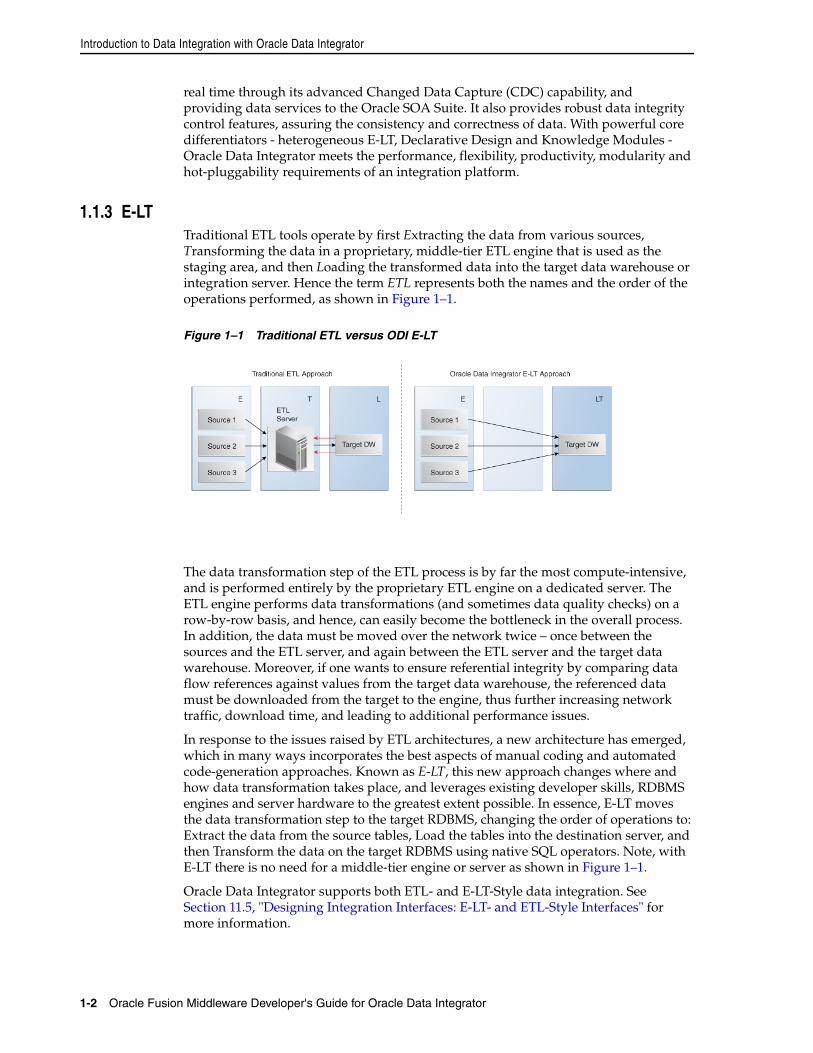
Introduction to Data Integration with Oracle Data Integrator
1-2 Oracle Fusion Middleware Developer's Guide for Oracle Data Integrator
real time through its advanced Changed Data Capture (CDC) capability, and providing data services to the Oracle SOA Suite. It also provides robust data integrity control features, assuring the consistency and correctness of data. With powerful core differentiators - heterogeneous E-LT, Declarative Design and Knowledge Modules - Oracle Data Integrator meets the performance, flexibility, productivity, modularity and hot-pluggability requirements of an integration platform.
1.1.3 E-LTTraditional ETL tools operate by first Extracting the data from various sources, Transforming the data in a proprietary, middle-tier ETL engine that is used as the staging area, and then Loading the transformed data into the target data warehouse or integration server. Hence the term ETL represents both the names and the order of the operations performed, as shown in Figure 1–1.
Figure 1–1 Traditional ETL versus ODI E-LT
The data transformation step of the ETL process is by far the most compute-intensive, and is performed entirely by the proprietary ETL engine on a dedicated server. The ETL engine performs data transformations (and sometimes data quality checks) on a row-by-row basis, and hence, can easily become the bottleneck in the overall process. In addition, the data must be moved over the network twice – once between the sources and the ETL server, and again between the ETL server and the target data warehouse. Moreover, if one wants to ensure referential integrity by comparing data flow references against values from the target data warehouse, the referenced data must be downloaded from the target to the engine, thus further increasing network traffic, download time, and leading to additional performance issues.
In response to the issues raised by ETL architectures, a new architecture has emerged, which in many ways incorporates the best aspects of manual coding and automated code-generation approaches. Known as E-LT, this new approach changes where and how data transformation takes place, and leverages existing developer skills, RDBMS engines and server hardware to the greatest extent possible. In essence, E-LT moves the data transformation step to the target RDBMS, changing the order of operations to: Extract the data from the source tables, Load the tables into the destination server, and then Transform the data on the target RDBMS using native SQL operators. Note, with E-LT there is no need for a middle-tier engine or server as shown in Figure 1–1.
Oracle Data Integrator supports both ETL- and E-LT-Style data integration. See Section 11.5, "Designing Integration Interfaces: E-LT- and ETL-Style Interfaces" for more information.
Oracle Data Integrator Concepts
Introduction to Oracle Data Integrator 1-3
1.2 Oracle Data Integrator ConceptsThis section provides an introduction to the main concepts of Oracle Data Integrator.
1.2.1 Introduction to Declarative DesignTo design an integration process with conventional ETL systems, a developer needs to design each step of the process: Consider, for example, a common case in which sales figures must be summed over time for different customer age groups. The sales data comes from a sales management database, and age groups are described in an age distribution file. In order to combine these sources then insert and update appropriate records in the customer statistics systems, you must design each step, which includes:
1. Load the customer sales data in the engine
2. Load the age distribution file in the engine
3. Perform a lookup between the customer sales data and the age distribution data
4. Aggregate the customer sales grouped by age distribution
5. Load the target sales statistics data into the engine
6. Determine what needs to be inserted or updated by comparing aggregated information with the data from the statistics system
7. Insert new records into the target
8. Update existing records into the target
This method requires specialized skills, depending on the steps that need to be designed. It also requires significant efforts in development, because even repetitive succession of tasks, such as managing inserts/updates in a target, need to be developed into each task. Finally, with this method, maintenance requires significant effort. Changing the integration process requires a clear understanding of what the process does as well as the knowledge of how it is done. With the conventional ETL method of design, the logical and technical aspects of the integration are intertwined.Declarative Design is a design method that focuses on “What” to do (the Declarative Rules) rather than “How” to do it (the Process). In our example, “What” the process does is:
■ Relate the customer age from the sales application to the age groups from the statistical file
■ Aggregate customer sales by age groups to load sales statistics
“How” this is done, that is the underlying technical aspects or technical strategies for performing this integration task – such as creating temporary data structures or calling loaders – is clearly separated from the declarative rules.
Declarative Design in Oracle Data Integrator uses the well known relational paradigm to declare in the form of an Interface the declarative rules for a data integration task, which includes designation of sources, targets, and transformations.
Declarative rules often apply to metadata to transform data and are usually described in natural language by business users. In a typical data integration project (such as a Data Warehouse project), these rules are defined during the specification phase in documents written by business analysts in conjunction with project managers. They can very often be implemented using SQL expressions, provided that the metadata they refer to is known and qualified in a metadata repository.
The four major types of Declarative Rules are mappings, joins, filters and constraints:
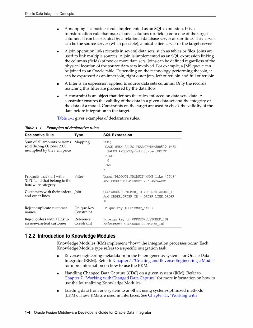
Oracle Data Integrator Concepts
1-4 Oracle Fusion Middleware Developer's Guide for Oracle Data Integrator
■ A mapping is a business rule implemented as an SQL expression. It is a transformation rule that maps source columns (or fields) onto one of the target columns. It can be executed by a relational database server at run-time. This server can be the source server (when possible), a middle tier server or the target server.
■ A join operation links records in several data sets, such as tables or files. Joins are used to link multiple sources. A join is implemented as an SQL expression linking the columns (fields) of two or more data sets. Joins can be defined regardless of the physical location of the source data sets involved. For example, a JMS queue can be joined to an Oracle table. Depending on the technology performing the join, it can be expressed as an inner join, right outer join, left outer join and full outer join.
■ A filter is an expression applied to source data sets columns. Only the records matching this filter are processed by the data flow.
■ A constraint is an object that defines the rules enforced on data sets’ data. A constraint ensures the validity of the data in a given data set and the integrity of the data of a model. Constraints on the target are used to check the validity of the data before integration in the target.
Table 1–1 gives examples of declarative rules.
1.2.2 Introduction to Knowledge ModulesKnowledge Modules (KM) implement “how” the integration processes occur. Each Knowledge Module type refers to a specific integration task:
■ Reverse-engineering metadata from the heterogeneous systems for Oracle Data Integrator (RKM). Refer to Chapter 5, "Creating and Reverse-Engineering a Model" for more information on how to use the RKM.
■ Handling Changed Data Capture (CDC) on a given system (JKM). Refer to Chapter 7, "Working with Changed Data Capture" for more information on how to use the Journalizing Knowledge Modules.
■ Loading data from one system to another, using system-optimized methods (LKM). These KMs are used in interfaces. See Chapter 11, "Working with
Table 1–1 Examples of declarative rules
Declarative Rule Type SQL Expression
Sum of all amounts or items sold during October 2005 multiplied by the item price
Mapping SUM( CASE WHEN SALES.YEARMONTH=200510 THEN SALES.AMOUNT*product.item_PRICE ELSE 0 END)
Products that start with ’CPU’ and that belong to the hardware category
Filter Upper(PRODUCT.PRODUCT_NAME)like ’CPU%’And PRODCUT.CATEGORY = ’HARDWARE’
Customers with their orders and order lines
Join CUSTOMER.CUSTOMER_ID = ORDER.ORDER_IDAnd ORDER.ORDER_ID = ORDER_LINE.ORDER_ID
Reject duplicate customer names
Unique Key Constraint
Unique key (CUSTOMER_NAME)
Reject orders with a link to an non-existent customer
Reference Constraint
Foreign key on ORDERS(CUSTOMER_ID) references CUSTOMER(CUSTOMER_ID)
Oracle Data Integrator Concepts
Introduction to Oracle Data Integrator 1-5
Integration Interfaces" for more information on how to use the Loading Knowledge Modules.
■ Integrating data in a target system, using specific strategies (insert/update, slowly changing dimensions) (IKM). These KMs are used in interfaces. See Chapter 11, "Working with Integration Interfaces"for more information on how to use the Integration Knowledge Modules.
■ Controlling Data Integrity on the data flow (CKM). These KMs are used in data model’s static check and interfaces flow checks. See Chapter 5, "Creating and Reverse-Engineering a Model" and Chapter 11, "Working with Integration Interfaces"for more information on how to use the Check Knowledge Modules.
■ Exposing data in the form of web services (SKM). Refer to Chapter 8, "Working with Data Services" for more information on how to use the Service Knowledge Modules.
A Knowledge Module is a code template for a given integration task. This code is independent of the Declarative Rules that need to be processed. At design-time, a developer creates the Declarative Rules describing integration processes. These Declarative Rules are merged with the Knowledge Module to generate code ready for runtime. At runtime, Oracle Data Integrator sends this code for execution to the source and target systems it leverages in the E-LT architecture for running the process.
Knowledge Modules cover a wide range of technologies and techniques. Knowledge Modules provide additional flexibility by giving users access to the most-appropriate or finely tuned solution for a specific task in a given situation. For example, to transfer data from one DBMS to another, a developer can use any of several methods depending on the situation:
■ The DBMS loaders (Oracle’s SQL*Loader, Microsoft SQL Server’s BCP, Teradata TPump) can dump data from the source engine to a file then load this file to the target engine
■ The database link features (Oracle Database Links, Microsoft SQL Server’s Linked Servers) can transfer data directly between servers
These technical strategies amongst others corresponds to Knowledge Modules tuned to exploit native capabilities of given platforms.
Knowledge modules are also fully extensible. Their code is opened and can be edited through a graphical user interface by technical experts willing to implement new integration methods or best practices (for example, for higher performance or to comply with regulations and corporate standards). Without having the skill of the technical experts, developers can use these custom Knowledge Modules in the integration processes.
For more information on Knowledge Modules, refer to the Connectivity and Modules Guide for Oracle Data Integrator and the Knowledge Module Developer's Guide for Oracle Data Integrator.
1.2.3 Introduction to Integration InterfacesAn integration interface is an Oracle Data Integrator object stored that enables the loading of one target datastore with data transformed from one or more source datastores, based on declarative rules implemented as mappings, joins, filters and constraints.
An integration interface also references the Knowledge Modules (code templates) that will be used to generate the integration process.
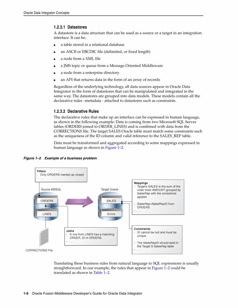
Oracle Data Integrator Concepts
1-6 Oracle Fusion Middleware Developer's Guide for Oracle Data Integrator
1.2.3.1 DatastoresA datastore is a data structure that can be used as a source or a target in an integration interface. It can be:
■ a table stored in a relational database
■ an ASCII or EBCDIC file (delimited, or fixed length)
■ a node from a XML file
■ a JMS topic or queue from a Message Oriented Middleware
■ a node from a enterprise directory
■ an API that returns data in the form of an array of records
Regardless of the underlying technology, all data sources appear in Oracle Data Integrator in the form of datastores that can be manipulated and integrated in the same way. The datastores are grouped into data models. These models contain all the declarative rules –metadata - attached to datastores such as constraints.
1.2.3.2 Declarative RulesThe declarative rules that make up an interface can be expressed in human language, as shown in the following example: Data is coming from two Microsoft SQL Server tables (ORDERS joined to ORDER_LINES) and is combined with data from the CORRECTIONS file. The target SALES Oracle table must match some constraints such as the uniqueness of the ID column and valid reference to the SALES_REP table.
Data must be transformed and aggregated according to some mappings expressed in human language as shown in Figure 1–2.
Figure 1–2 Example of a business problem
Translating these business rules from natural language to SQL expressions is usually straightforward. In our example, the rules that appear in Figure 1–2 could be translated as shown in Table 1–2.
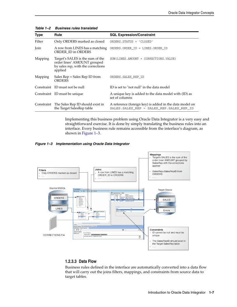
Oracle Data Integrator Concepts
Introduction to Oracle Data Integrator 1-7
Implementing this business problem using Oracle Data Integrator is a very easy and straightforward exercise. It is done by simply translating the business rules into an interface. Every business rule remains accessible from the interface’s diagram, as shown in Figure 1–3.
Figure 1–3 Implementation using Oracle Data Integrator
1.2.3.3 Data FlowBusiness rules defined in the interface are automatically converted into a data flow that will carry out the joins filters, mappings, and constraints from source data to target tables.
Table 1–2 Business rules translated
Type Rule SQL Expression/Constraint
Filter Only ORDERS marked as closed ORDERS.STATUS = ’CLOSED’
Join A row from LINES has a matching ORDER_ID in ORDERS
ORDERS.ORDER_ID = LINES.ORDER_ID
Mapping Target’s SALES is the sum of the order lines’ AMOUNT grouped by sales rep, with the corrections applied
SUM(LINES.AMOUNT + CORRECTIONS.VALUE)
Mapping Sales Rep = Sales Rep ID from ORDERS
ORDERS.SALES_REP_ID
Constraint ID must not be null ID is set to "not null" in the data model
Constraint ID must be unique A unique key is added to the data model with (ID) as set of columns
Constraint The Sales Rep ID should exist in the Target SalesRep table
A reference (foreign key) is added in the data model on SALES.SALES_REP = SALES_REP.SALES_REP_ID
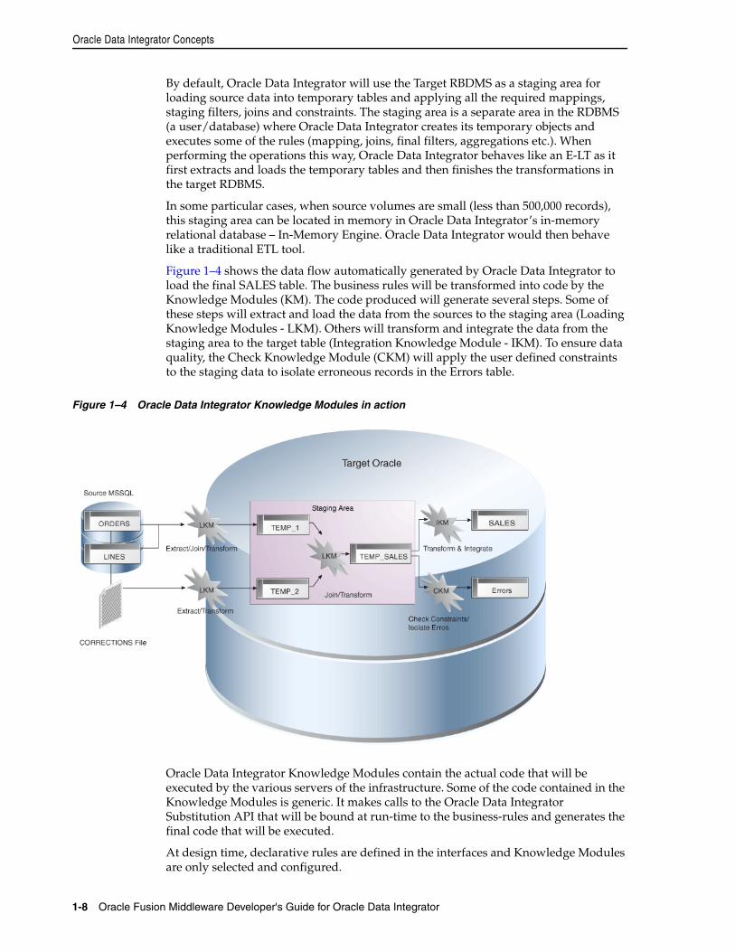
Oracle Data Integrator Concepts
1-8 Oracle Fusion Middleware Developer's Guide for Oracle Data Integrator
By default, Oracle Data Integrator will use the Target RBDMS as a staging area for loading source data into temporary tables and applying all the required mappings, staging filters, joins and constraints. The staging area is a separate area in the RDBMS (a user/database) where Oracle Data Integrator creates its temporary objects and executes some of the rules (mapping, joins, final filters, aggregations etc.). When performing the operations this way, Oracle Data Integrator behaves like an E-LT as it first extracts and loads the temporary tables and then finishes the transformations in the target RDBMS.
In some particular cases, when source volumes are small (less than 500,000 records), this staging area can be located in memory in Oracle Data Integrator’s in-memory relational database – In-Memory Engine. Oracle Data Integrator would then behave like a traditional ETL tool.
Figure 1–4 shows the data flow automatically generated by Oracle Data Integrator to load the final SALES table. The business rules will be transformed into code by the Knowledge Modules (KM). The code produced will generate several steps. Some of these steps will extract and load the data from the sources to the staging area (Loading Knowledge Modules - LKM). Others will transform and integrate the data from the staging area to the target table (Integration Knowledge Module - IKM). To ensure data quality, the Check Knowledge Module (CKM) will apply the user defined constraints to the staging data to isolate erroneous records in the Errors table.
Figure 1–4 Oracle Data Integrator Knowledge Modules in action
Oracle Data Integrator Knowledge Modules contain the actual code that will be executed by the various servers of the infrastructure. Some of the code contained in the Knowledge Modules is generic. It makes calls to the Oracle Data Integrator Substitution API that will be bound at run-time to the business-rules and generates the final code that will be executed.
At design time, declarative rules are defined in the interfaces and Knowledge Modules are only selected and configured.
Typical ODI Integration Projects
Introduction to Oracle Data Integrator 1-9
At run-time, code is generated and every Oracle Data Integrator API call in the Knowledge Modules (enclosed by <% and %>) is replaced with its corresponding object name or expression, with respect to the metadata provided in the Repository. The generated code is orchestrated by Oracle Data Integrator run-time component - the Agent – on the source and target systems to make them perform the processing, as defined in the E-LT approach.
Refer to Chapter 11, "Working with Integration Interfaces" for more information on how to work with integration interfaces.
1.3 Typical ODI Integration ProjectsOracle Data Integrator provides a wide range of integration features. This section introduces the most typical ODI Integration Projects.
1.3.1 Batch Oriented IntegrationODI is a comprehensive data integration platform with a built-in connectivity to all major databases, data warehouse and analytic applications providing high-volume and high-performance batch integration.
The main goal of a data warehouse is to consolidate and deliver accurate indicators to business users to help them make decisions regarding their everyday business. A typical project is composed of several steps and milestones. Some of these are:
■ Defining business needs (Key Indicators)
■ Identifying source data that concerns key indicators; specifying business rules to transform source information into key indicators
■ Modeling the data structure of the target warehouse to store the key indicators
■ Populating the indicators by implementing business rules
■ Measuring the overall accuracy of the data by setting up data quality rules
■ Developing reports on key indicators
■ Making key indicators and metadata available to business users through adhoc query tools or predefined reports
■ Measuring business users’ satisfaction and adding/modifying key indicators
Oracle Data Integrator will help you cover most of these steps, from source data investigation to metadata lineage, and through loading and data quality audit. With its repository, ODI will centralize the specification and development efforts and provide a unique architecture on which the project can rely to succeed.
Scheduling and Operating ScenariosScheduling and operating scenarios is usually done in the Test and Production environments in separate Work Repositories. Any scenario can be scheduled by an ODI Agent or by any external scheduler, as scenarios can be invoked by an operating system command.
When scenarios are running in production, agents generate execution logs in an ODI Work Repository. These logs can be monitored either through the Operator Navigator or through any web browser when Oracle Data Integrator Console is setup. Failing jobs can be restarted and ad-hoc tasks submitted for execution.
Typical ODI Integration Projects
1-10 Oracle Fusion Middleware Developer's Guide for Oracle Data Integrator
E-LTODI uses a unique E-LT architecture that leverages the power of existing RDBMS engines by generating native SQL and bulk loader control scripts to execute all transformations.
1.3.2 Event Oriented IntegrationCapturing events from a Message Oriented Middleware or an Enterprise Service Bus has become a common task in integrating applications in a real-time environment. Applications and business processes generate messages for several subscribers, or they consume messages from the messaging infrastructure.
Oracle Data Integrator includes technology to support message-based integration and that complies with the Java Message Services (JMS) standard. For example, a transformation job within Oracle Data Integrator can subscribe and source messages from any message queue or topic. Messages are captured and transformed in real time and then written to the target systems.
Other use cases of this type of integration might require capturing changes at the database level. Oracle Data Integrator Changed Data Capture (CDC) capability identifies and captures inserted, updated, or deleted data from the source and makes it available for integration processes.
ODI provides two methods for tracking changes from source datastores to the CDC framework: triggers and RDBMS log mining. The first method can be deployed on most RDBMS that implement database triggers. This method is optimized to minimize overhead on the source systems. For example, changed data captured by the trigger is not duplicated, minimizing the number of input/output operations, which slow down source systems. The second method involves mining the RDBMS logs—the internal change history of the database engine. This has little impact on the system’s transactional performance and is supported for Oracle (through the Log Miner feature) and IBM DB2/400.
The CDC framework used to manage changes, based on Knowledge Modules, is generic and open, so the change-tracking method can be customized. Any third-party change provider can be used to load the framework with changes.
Changes frequently involve several data sources at the same time. For example, when an order is created, updated, or deleted, both the orders table and the order lines table are involved. When processing a new order line, it is important that the new order, to which the line is related, is taken into account too. ODI provides a mode of change tracking called Consistent Set CDC. This mode allows for processing sets of changes for which data consistency is guaranteed.
For example, incoming orders can be detected at the database level using CDC. These new orders are enriched and transformed by ODI before being posted to the appropriate message queue or topic. Other applications such as Oracle BPEL or Oracle Business Activity Monitoring can subscribe to these messages, and the incoming events will trigger the appropriate business processes.
For more information on how to use the CDC framework in ODI, refer to Chapter 7, "Working with Changed Data Capture".
1.3.3 Service-Oriented ArchitectureOracle Data Integrator can be integrated seamlessly in a Service Oriented Architecture (SOA) in several ways:
Typical ODI Integration Projects
Introduction to Oracle Data Integrator 1-11
Data Services are specialized Web services that provide access to data stored in database tables. Coupled with the Changed Data Capture capability, data services can also provide access to the changed records for a given subscriber. Data services are automatically generated by Oracle Data Integrator and deployed as Web services to a Web container, usually a Java application server. For more information on how to set up, generate and deploy data services, refer to Chapter 8, "Working with Data Services".
Oracle Data Integrator can also expose its transformation processes as Web services to enable applications to use them as integration services. For example, a LOAD_SALES batch process used to update the CRM application can be triggered as a Web service from any service-compliant application, such as Oracle BPEL, Oracle Enterprise Service Bus, or Oracle Business Activity Monitoring. Transformations developed using ODI can therefore participate in the broader Service Oriented Architecture initiative.
Third-party Web services can be invoked as part of an ODI workflow and used as part of the data integration processes. Requests are generated on the fly and responses processed through regular transformations. Suppose, for example, that your company subscribed to a third-party service that exposes daily currency exchange rates as a Web service. If you want this data to update your multiple currency data warehouse, ODI automates this task with a minimum of effort. You would simply invoke the Web service from your data warehouse workflow and perform any appropriate transformation to the incoming data to make it fit a specific format. For more information on how to use web services in ODI, refer to Chapter 15, "Working with Web Services in Oracle Data Integrator".
1.3.4 Data Quality with ODIWith an approach based on declarative rules, Oracle Data Integrator is the most appropriate tool to help you build a data quality framework to track data inconsistencies.
Oracle Data Integrator uses declarative data integrity rules defined in its centralized metadata repository. These rules are applied to application data to guarantee the integrity and consistency of enterprise information. The Data Integrity benefits add to the overall Data Quality initiative and facilitate integration with existing and future business processes addressing this particular need.
Oracle Data Integrator automatically retrieves existing rules defined at the data level (such as database constraints) by a reverse-engineering process. ODI also allows developers to define additional, user-defined declarative rules that may be inferred from data discovery and profiling within ODI, and immediately checked.
Oracle Data Integrator provides a built-in framework to check the quality of your data in two ways:
■ Check data in your data servers, to validate that this data does not violate any of the rules declared on the datastores in Oracle Data Integrator. This data quality check is called a static check and is performed on data models and datastores. This type of check allows you to profile the quality of the data against rules that are not enforced by their storage technology.
■ Check data while it is moved and transformed by an interface, in a flow check that checks the data flow against the rules defined on the target datastore. With such a check, correct data can be integrated into the target datastore while incorrect data is automatically moved into error tables.
Typical ODI Integration Projects
1-12 Oracle Fusion Middleware Developer's Guide for Oracle Data Integrator
Both static and flow checks are using the constraints that are defined in the datastores and data models, and both use the Check Knowledge Modules (CKMs). For more information refer to Section 11.3.7, "Set up Flow Control and Post-Integration Control".
These checks check the integrity of the data and validate constraints. For advanced data quality projects (for example for name and address cleansing projects) as well as advanced data profiling, the Oracle Data Profiling and Oracle Data Quality for Data Integrator products can be used along with Oracle Date Integrator.
Oracle Data Quality and Oracle Data Profiling IntegrationOracle Data Profiling and Oracle Data Quality for Data Integrator (also referred to as Oracle Data Quality Products) extend the inline Data Quality features of Oracle Data Integrator to provide more advanced data governance capabilities.
Oracle Data Profiling is a data investigation and quality monitoring tool. It allows business users to assess the quality of their data through metrics, to discover or deduce rules based on this data, and to monitor the evolution of data quality over time.
Oracle Data Quality for Data Integrator is a comprehensive award-winning data quality platform that covers even the most complex data quality needs. Its powerful rule-based engine and its robust and scalable architecture places data quality and name and address cleansing at the heart of an enterprise data integration strategy.
For more information on Oracle Data Quality and Oracle Data Profiling refer to Chapter 16, "Working with Oracle Data Quality Products".
1.3.5 Managing EnvironmentsIntegration projects exist in different environments during their lifecycle (development, test, product) and may even run in different environments in production (multiple site deployment). Oracle Data Integrator makes easier the definition and maintenance of these environments, as well as the lifecycle of the project across these environments using the Topology
The Topology describes the physical and logical architecture of your Information System. It gives you a very flexible way of managing different servers, environments and agents. All the information of the Topology is stored in the master repository and is therefore centralized for an optimized administration. All the objects manipulated within Work Repositories refer to the Topology. That’s why it is the most important starting point when defining and planning your architecture.
The Topology is composed of data servers, physical and logical schemas, and contexts.
Data servers describe connections to your actual physical application servers and databases. They can represent for example:
■ An Oracle Instance
■ An IBM DB2 Database
■ A Microsoft SQL Server Instance
■ A Sybase ASE Server
■ A File System
■ An XML File
■ A Microsoft Excel Workbook
■ and so forth.
Typical ODI Integration Projects
Introduction to Oracle Data Integrator 1-13
At runtime, Oracle Data Integrator uses the connection information you have described to connect to the servers.
Physical schemas indicate the physical location of the datastores (tables, files, topics, queues) inside a data server. All the physical schemas that need to be accessed have to be registered under their corresponding data server, physical schemas are used to prefix object names and access them with their qualified names. When creating a physical schema, you need to specify a temporary, or work schema that will store temporary or permanent object needed at runtime.
A logical schema is an alias that allows a unique name to be given to all the physical schemas containing the same datastore structures. The aim of the logical schema is to ensure the portability of procedures and models on different design-time and run-time environments.
A Context represents one of these environments. Contexts are used to group physical resources belonging to the same environment.
Typical projects will have separate environments for Development, Test and Production. Some projects will even have several duplicated Test or Production environments. For example, you may have several production contexts for subsidiaries running their own production systems (Production New York, Production Boston etc). There is obviously a difference between the logical view of the information system and its physical implementation as described in Figure 1–5.
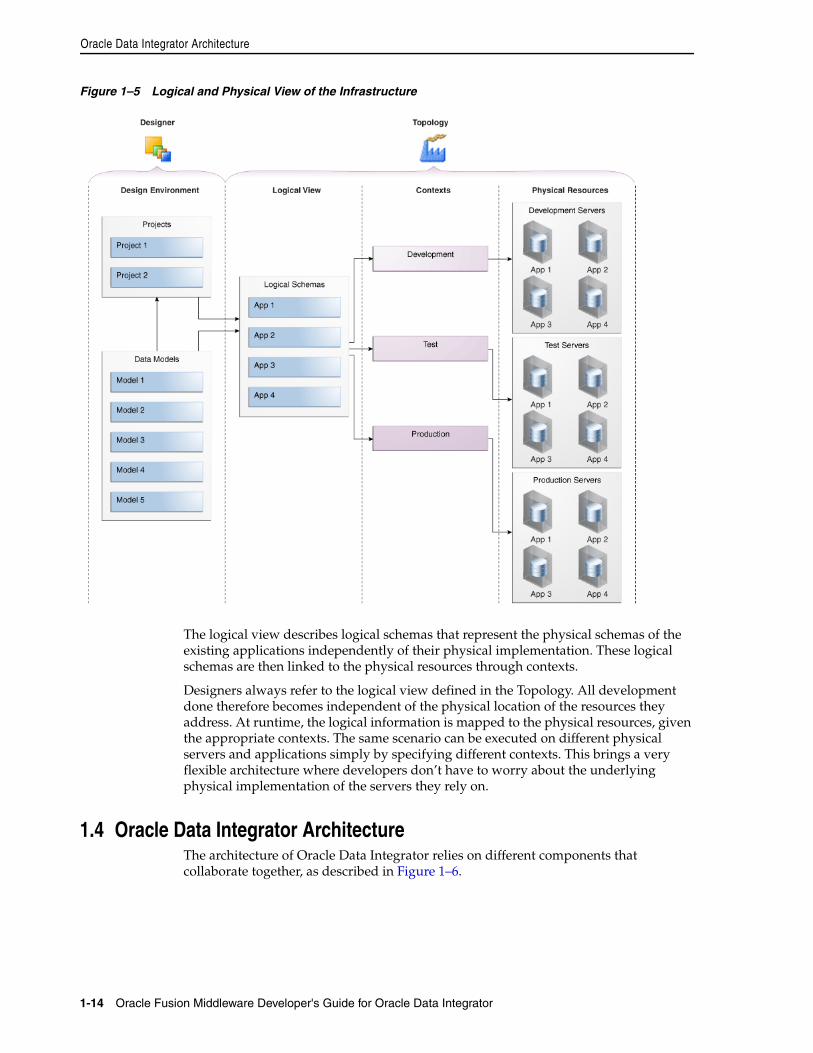
Oracle Data Integrator Architecture
1-14 Oracle Fusion Middleware Developer's Guide for Oracle Data Integrator
Figure 1–5 Logical and Physical View of the Infrastructure
The logical view describes logical schemas that represent the physical schemas of the existing applications independently of their physical implementation. These logical schemas are then linked to the physical resources through contexts.
Designers always refer to the logical view defined in the Topology. All development done therefore becomes independent of the physical location of the resources they address. At runtime, the logical information is mapped to the physical resources, given the appropriate contexts. The same scenario can be executed on different physical servers and applications simply by specifying different contexts. This brings a very flexible architecture where developers don’t have to worry about the underlying physical implementation of the servers they rely on.
1.4 Oracle Data Integrator ArchitectureThe architecture of Oracle Data Integrator relies on different components that collaborate together, as described in Figure 1–6.
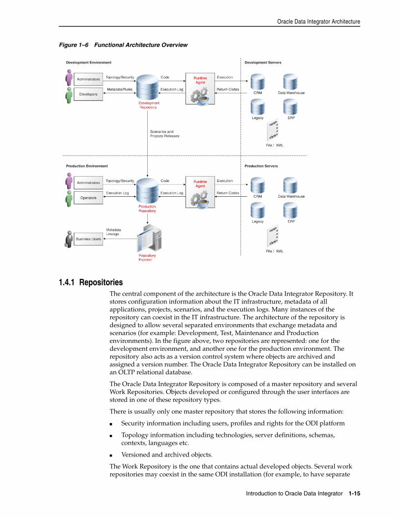
Oracle Data Integrator Architecture
Introduction to Oracle Data Integrator 1-15
Figure 1–6 Functional Architecture Overview
1.4.1 RepositoriesThe central component of the architecture is the Oracle Data Integrator Repository. It stores configuration information about the IT infrastructure, metadata of all applications, projects, scenarios, and the execution logs. Many instances of the repository can coexist in the IT infrastructure. The architecture of the repository is designed to allow several separated environments that exchange metadata and scenarios (for example: Development, Test, Maintenance and Production environments). In the figure above, two repositories are represented: one for the development environment, and another one for the production environment. The repository also acts as a version control system where objects are archived and assigned a version number. The Oracle Data Integrator Repository can be installed on an OLTP relational database.
The Oracle Data Integrator Repository is composed of a master repository and several Work Repositories. Objects developed or configured through the user interfaces are stored in one of these repository types.
There is usually only one master repository that stores the following information:
■ Security information including users, profiles and rights for the ODI platform
■ Topology information including technologies, server definitions, schemas, contexts, languages etc.
■ Versioned and archived objects.
The Work Repository is the one that contains actual developed objects. Several work repositories may coexist in the same ODI installation (for example, to have separate
Oracle Data Integrator Architecture
1-16 Oracle Fusion Middleware Developer's Guide for Oracle Data Integrator
environments or to match a particular versioning life cycle). A Work Repository stores information for:
■ Models, including schema definition, datastores structures and metadata, fields and columns definitions, data quality constraints, cross references, data lineage etc.
■ Projects, including business rules, packages, procedures, folders, Knowledge Modules, variables etc.
■ Scenario execution, including scenarios, scheduling information and logs.
When the Work Repository contains only the execution information (typically for production purposes), it is then called an Execution Repository.
For more information on how to manage ODI repositories, refer to Chapter 3, "Administering the Oracle Data Integrator Repositories".
1.4.2 User InterfacesAdministrators, Developers and Operators use the Oracle Data Integrator Studio to access the repositories. This Fusion Client Platform (FCP) based UI is used for administering the infrastructure (security and topology), reverse-engineering the metadata, developing projects, scheduling, operating and monitoring executions.
Business users (as well as developers, administrators and operators), can have read access to the repository, perform topology configuration and production operations through a web based UI called Oracle Data Integrator Console. This Web application can deployed in a Java EE application server such as Oracle WebLogic.
ODI Studio provides four Navigators for managing the different aspects and steps of an ODI integration project:
■ Topology Navigator
■ Designer Navigator
■ Operator Navigator
■ Security Navigator
Topology NavigatorTopology Navigator is used to manage the data describing the information system's physical and logical architecture. Through Topology Navigator you can manage the topology of your information system, the technologies and their datatypes, the data servers linked to these technologies and the schemas they contain, the contexts, the language and the agents, as well as the repositories. The site, machine, and data server descriptions will enable Oracle Data Integrator to execute the same interfaces in different environments.
Designer NavigatorDesigner Navigator is used to design data integrity checks and to build transformations such as for example:
■ Automatic reverse-engineering of existing applications or databases
■ Graphical development and maintenance of transformation and integration interfaces
■ Visualization of data flows in the interfaces
■ Automatic documentation generation
Oracle Data Integrator Architecture
Introduction to Oracle Data Integrator 1-17
■ Customization of the generated code
The main objects you handle through Designer Navigator are Models and Projects.
Operator NavigatorOperator Navigator is the production management and monitoring tool. It is designed for IT production operators. Through Operator Navigator, you can manage your interface executions in the sessions, as well as the scenarios in production.
Security NavigatorSecurity Navigator is the tool for managing the security information in Oracle Data Integrator. Through Security Navigator you can create users and profiles and assign user rights for methods (edit, delete, etc) on generic objects (data server, datatypes, etc), and fine-tune these rights on the object instances (Server 1, Server 2, etc).
1.4.3 Design-time ProjectsA typical project is composed of several steps and milestones.
Some of these are:
■ Define the business needs
■ Identify and declare the sources and targets in the Topology
■ Design and Reverse-engineer source and target data structures in the form of data models
■ Implement data quality rules on these data models and perform static checks on these data models to validate the data quality rules
■ Develop integration interfaces using datastores from these data models as sources and target
■ Develop additional components for tasks that cannot be achieved using interfaces, such as Receiving and sending e-mails, handling files (copy, compress, rename and such), executing web services
■ Integrate interfaces and additional components for building Package workflows
■ Version your work and release it in the form of scenarios
■ Schedule and operate scenarios.
Oracle Data Integrator will help you cover most of these steps, from source data investigation to metadata lineage, and through loading and data quality audit. With its repository, Oracle Data Integrator will centralize the specification and development efforts and provide a unique architecture on which the project can rely to succeed.
Chapter 2, "Oracle Data Integrator QuickStart" introduces you to the basic steps of creating an integration project with Oracle Data Integrator. Chapter 9, "Creating an Integration Project" gives you more detailed information on the several steps of creating an integration project in ODI.
1.4.4 Run-Time AgentAt design time, developers generate scenarios from the business rules that they have designed. The code of these scenarios is then retrieved from the repository by the Run-Time Agent. This agent then connects to the data servers and orchestrates the code execution on these servers. It retrieves the return codes and messages for the
Oracle Data Integrator Architecture
1-18 Oracle Fusion Middleware Developer's Guide for Oracle Data Integrator
execution, as well as additional logging information – such as the number of processed records, execution time etc. - in the Repository.
The Agent comes in two different flavors:
■ The Java EE Agent can be deployed as a web application and benefit from the features of an application server.
■ The Standalone Agent runs in a simple Java Machine and can be deployed where needed to perform the integration flows.
Both these agents are multi-threaded java programs that support load balancing and can be distributed across the information system. This agent holds its own execution schedule which can be defined in Oracle Data Integrator, and can also be called from an external scheduler. It can also be invoked from a Java API or a web service interface. Refer to Chapter 4, "Setting-up the Topology" for more information on how to create and manage agents.
2
Oracle Data Integrator QuickStart 2-1
2Oracle Data Integrator QuickStart
The Oracle Data Integrator QuickStart will introduce you to the basic steps of creating an integration project with Oracle Data Integrator and show you how to put them immediately to work for you. It will help you get started with Oracle Data Integrator by pointing out only the basic functionalities and the minimum required steps.
This section is not intended to be used for advanced configuration, usage or troubleshooting.
2.1 Oracle Data Integrator QuickStart ListTo perform the minimum required steps of an Oracle Data Integrator integration project follow the ODI QuickStart list and go directly to the specified section of this guide.
Before performing the QuickStart procedure ensure that you have:
1. Installed Oracle Data Integrator according to the instructions in the Oracle Fusion Middleware Installation Guide for Oracle Data Integrator.
2. Set up the Oracle Data Integrator repository architecture. This means create the repositories to store the metadata for the applications involved in the transformation and integration processing, the developed project versions and all of the information required for their use (planning, scheduling and execution reports). To set up the Oracle Data Integrator repository architecture:
1. You need to create one master repository containing information on the topology of a company's IT resources, on security and on version management of projects and data models. Refer to Section 3.3, "Creating the Master Repository"for more details.
To test your master repository connection, refer to Section 3.4, "Connecting to the Master Repository".
2. You need to create at least one Work Repository containing information about data models, projects, and their operations. Refer to Section 3.5, "Creating a Work Repository"for more details.
To test your work repository connection and access this repository through Designer and Operator, refer to the section Section 3.6, "Connecting to a Work Repository".
ODI QuickStart listThe first part of the QuickStart (steps 1 to 3) consists of setting up the topology of your information system by defining the data servers, the schemas they contain, and the
Oracle Data Integrator QuickStart List
2-2 Oracle Fusion Middleware Developer's Guide for Oracle Data Integrator
contexts. Refer to the Chapter 1, "Introduction to Oracle Data Integrator" if you are not familiar with these concepts.
The second part of the QuickStart (step 4) consists of creating a model. A model is a set of datastores corresponding to data structures contained in a physical schema: tables, files, JMS messages, elements from an XML file are represented as datastores.
The third part of the QuickStart (steps 5 to 7) consists of creating your integration project. In this project you create integration interfaces to load data from one or several source datastores to one target datastore.
The last part of the QuickStart (steps 8 and 9) consists of executing the interface you have create d in step 7 and viewing and monitoring the execution results.
1. To connect source and target systems you need to declare data servers. A data server can be a database, a MOM, a connector or a file server and is always linked with one specific technology. How to create a data server corresponding to the servers used in Oracle Data Integrator is covered in the Chapter 4.2.2, "Creating a Data Server".
2. A physical schema is a defining component of a data server. It allows the datastores to be classified and the objects stored in the data server to be accessed. For each data server, create the physical schemas as described in Chapter 4.2.3, "Creating a Physical Schema". Use the default Global context.
3. In Oracle Data Integrator, you perform developments on top of a logical topology. Refer to the Chapter 1, "Introduction to Oracle Data Integrator" if you are not familiar with the logical architecture. Create the logical schemas and associate them with the physical schemas in the Global context. See Chapter 4.2.4, "Creating a Logical Schema" for more information.
4. Integration interfaces use data models containing the source and target datastores. Data Models are usually reverse-engineered from your data servers metadata into the Oracle Data Integrator repository. Create a model according to the Section 5.2, "Creating and Reverse-Engineering a Model".
5. The developed integration components are stored in a project. How to create a new project is covered in the Section 9.2, "Creating a New Project".
6. Integration interfaces use Knowledge Modules to generate their code. For more information refer to the E-LT concept in the Chapter 1, "Introduction to Oracle Data Integrator". Before creating integration interfaces you need to import the Knowledge Modules corresponding to the technology of your data. How to import a Knowledge Module is covered in the Section 19.2.3, "Importing Objects". Which Knowledge Modules you need to import is covered in the Oracle Fusion Middleware Connectivity and Knowledge Modules Guide for Oracle Data Integrator.
7. To load your target datastores with the data from the source datastores you need to create an interface. An interface consists of a set of rules that define the loading from one or more source datastores to one target datastore. How to create a new interface for your integration project is covered in the Section 11.3, "Creating an Interface".
8. Once you have finished creating the integration interface, you can execute it. The interface execution is covered in the Section 11.3.8, "Execute the Integration Interface". Select Local (No Agent) to execute the interface directly by Oracle Data Integrator.
9. You can view and monitor the execution results in Operator. How to follow the interface’s execution in Operator is covered in the Chapter 21, "Monitoring Integration Processes".

Oracle Data Integrator QuickStart List
Oracle Data Integrator QuickStart 2-3
10. An integration workflow may require the loading of several target datastores in a precise sequence. If you want to sequence your interfaces, create a package. This is optional step covered in Chapter 10.2, "Creating a new Package".

Oracle Data Integrator QuickStart List
2-4 Oracle Fusion Middleware Developer's Guide for Oracle Data Integrator
Part IIPart II Administering the Oracle Data Integrator
Architecture
This part describes the Oracle Data Integrator Architecture.
This part contains the following chapters:
■ Chapter 3, "Administering the Oracle Data Integrator Repositories"
■ Chapter 4, "Setting-up the Topology"

3
Administering the Oracle Data Integrator Repositories 3-1
3Administering the Oracle Data IntegratorRepositories
This chapter describes how to create and administer Oracle Data Integrator repositories. An overview of the repositories used in Oracle Data Integrator is provided.
This chapter includes the following sections:
■ Section 3.1, "Introduction to Oracle Data Integrator Repositories"
■ Section 3.2, "Creating Repository Storage Spaces"
■ Section 3.3, "Creating the Master Repository"
■ Section 3.4, "Connecting to the Master Repository"
■ Section 3.5, "Creating a Work Repository"
■ Section 3.6, "Connecting to a Work Repository"
■ Section 3.7, "Changing the Work Repository Password"
■ Section 3.8, "Advanced Actions for Administering Repositories"
3.1 Introduction to Oracle Data Integrator RepositoriesThere are two types of repositories in Oracle Data Integrator:
■ Master Repository: This is a data structure containing information on the topology of the company's IT resources, on security and on version management of projects and data models. This repository is stored on a relational database accessible in client/server mode from the different Oracle Data Integrator modules. In general, you need only one master repository. However, it may be necessary to create several master repositories in one of the following cases:
– Project construction over several sites not linked by a high-speed network (off-site development, for example).
– Necessity to clearly separate the interfaces' operating environments (development, test, production), including on the database containing the master repository. This may be the case if these environments are on several sites.
■ Work Repository: This is a data structure containing information on data models, projects, and their use. This repository is stored on a relational database accessible in client/server mode from the different Oracle Data Integrator modules. Several work repositories can be created with several master repositories if necessary.
Creating Repository Storage Spaces
3-2 Oracle Fusion Middleware Developer's Guide for Oracle Data Integrator
However, a work repository can be linked with only one master repository for version management purposes.
The standard method for creating repositories is using Repository Creation Utility (RCU). RCU automatically manages storage space as well as repository creation. However, if you want to create the repositories manually, it is possible to manually create and configure the repositories.
The steps needed to create and configure repositories are detailed in the following sections:
■ Section 3.2, "Creating Repository Storage Spaces"
■ Section 3.3, "Creating the Master Repository"
■ Section 3.4, "Connecting to the Master Repository"
■ Section 3.5, "Creating a Work Repository"
■ Section 3.6, "Connecting to a Work Repository"
Advanced actions for administering repositories are detailed in Section 3.8, "Advanced Actions for Administering Repositories".
3.2 Creating Repository Storage SpacesOracle Data Integrator repositories can be installed on database engines supported by Oracle Fusion Middleware 11g. For the latest list of supported databases versions as well as the requirements for each database, see:
http://www.oracle.com/technology/software/products/ias/files/fusion_certification.html
For each database that will contain a repository, a storage space must be created.
Your master repository can be stored in the same schema as one of your work repositories. However, you cannot create two different work repositories in the same schema.
The examples in the following table are supplied as a guide:
Note: Oracle recommends that you regularly perform the following maintenance operations: purge the execution logs in order to reduce the work repository size, and back up the Oracle Data Integrator repositories on the database.
Caution: For reasons of maintenance and back-up, we strongly recommend that repositories be stored in a different space from where your application data is kept (for example in a different schema for an Oracle database, or in a different database for Sybase or Microsoft SQL Server).
Creating the Master Repository
Administering the Oracle Data Integrator Repositories 3-3
3.3 Creating the Master RepositoryCreating the master repository creates an empty repository structure and seeds metadata (for example, technology definitions, or built-in security profiles) into this repository structure.
To create the master repository:
1. Open the New Gallery by choosing File > New.
2. In the New Gallery, in the Categories tree, select ODI.
Technology Steps to follow
Oracle Create a schema odim to host the Master repository and a schema odiw to host the work repository.
The schemas are created by the following SQL commands:
SQL> create user MY_SCHEMA identified by MY_PASS default tablespace MY_TBS temporary tablespace MY_TEMP; SQL> grant connect, resource to MY_SCHEMA;SQL> grant execute on dbms_lock to MY_SCHEMA;
Where:
MY_SCHEMA corresponds to the name of the schema you want to create.
MY_PASS corresponds to the password you have given it <MY_TBS> the Oracle tablespace where the data will be stored
MY_TEMP temporary default tablespace
Microsoft SQL Server or Sybase ASE
Create a database db_odim to host the master repository and a database db_odiw to host the work repository. Create two logins odim and odiw which have these databases by default.
Use Enterprise Manager to create the two databases db_odim and db_odiw.
Use Query Analyzer or I-SQL to launch the following commands:
CREATE LOGIN mylogin WITH PASSWORD = 'mypass', DEFAULT_DATABASE = defaultbase, DEFAULT_LANGUAGE = us_english;USE defaultbase;CREATE USER dbo FOR LOGIN mylogin;GO
Where:
mylogin corresponds to odim or odiw.
mypass corresponds to a password for these logins.
defaultbase corresponds to db_odim and db_odiw respectively.
Note: It is recommended to configure the Microsoft SQL Server databases that store the repository information with a case-sensitive collation. This enables reverse-engineering and creating multiple objects with the same name but a different case (for example: tablename and TableNAme).
DB2/400 Create a library odim to host the Master repository and a schema odiw to host the work repository. Create two users odim and odiw who have these libraries by default.
Note: The libraries must be created in the form of SQL collections.
Creating the Master Repository
3-4 Oracle Fusion Middleware Developer's Guide for Oracle Data Integrator
3. Select from the Items list the Master Repository Creation Wizard.
4. Click OK.
The Master Repository Creation wizard opens.
5. Specify the Database Connection parameters as follows:
■ Technology: From the list, select the technology that will host your master repository. Default is Oracle.
■ JDBC Driver: The driver used to access the technology, that will host the repository.
■ JDBC URL: The URL used to establish the JDBC connection to the database.
Note that the parameters JDBC Driver and URL are synchronized and the default values are technology dependant.
■ User: The user ID / login of the owner of the tables (for example, odim).
■ Password: This user's password.
■ DBA User: The database administrator’s username
■ DBA Password: This user’s password
6. Specify the Repository Configuration parameters as follows:
■ ID: A specific ID for the new repository, rather than the default 0.
7. Click Test Connection to test the connection to your master repository.
The Information dialog opens and informs you whether the connection has been established. If the connection fails, fix the connection to your master repository before moving to next step.
8. Click Next.
9. Do one of the following:
■ Select Use ODI Authentication to manage users using ODI’s internal security system and enter the following supervisor login information:
■ Select Use External Authentication to use an external enterprise identity store, such as Oracle Internet Directory, to manage user authentication and enter the following supervisor login information:
Note: It is strongly recommended that this ID is unique and not used for any other master repository, as it affects imports and exports between repositories
Properties Description
Supervisor User User name of the ODI supervisor.
Supervisor Password This user’s password
Confirm Password This user’s password
Properties Description
Supervisor User User name of the ODI supervisor
Connecting to the Master Repository
Administering the Oracle Data Integrator Repositories 3-5
10. Click Next.
11. Specify the password storage details:
■ Select Internal Password Storage if you want to store passwords in the Oracle Data Integrator master repository
■ Select External Password Storage if you want use JPS Credential Store Framework (CSF) to store the data server and context passwords in a remote credential store. Indicate the MBean Server Parameters to access the credential store. Refer to Chapter 23, "Managing the Security in Oracle Data Integrator" for more information.
12. In the Master Repository Creation Wizard click Finish to validate your entries.
Oracle Data Integrator begins creating your master repository. You can follow the procedure on your Messages – Log. To test your master repository, refer to the Section 3.4, "Connecting to the Master Repository".
3.4 Connecting to the Master RepositoryTo connect to the Master repository:
1. Open the New Gallery by choosing File > New.
2. In the New Gallery, in the Categories tree, select ODI.
3. Select from the Items list Create a New ODI Repository Login.
4. Click OK.
The Repository Connection Information dialog appears.
5. Specify the Oracle Data Integrator connection details as follows:
■ Login name: A generic alias (for example: Repository)
■ User: The ODI supervisor user name you have defined when creating the master repository or an ODI user name you have defined in the Security Navigator after having created the master repository.
■ Password: The ODI supervisor password you have defined when creating the master repository or an ODI user password you have defined in the Security Navigator after having created the master repository.
6. Specify the Database Connection (Master Repository) details as follows:
■ User: Database user ID/login of the schema (database, library) that contains the ODI master repository
■ Password: This user's password
Supervisor Password This user’s password
Note: In order to use the external authentication option, ODI Studio has to be configured for external authentication. See Section 23.3.2, "Setting Up External Authentication" for more information and restart ODI Studio.
Properties Description
Creating a Work Repository
3-6 Oracle Fusion Middleware Developer's Guide for Oracle Data Integrator
■ Driver List: Select the driver required to connect to the DBMS supporting the master repository you have just created from the dropdown list.
■ Driver Name: The complete driver name
■ JDBC URL: The URL used to establish the JDBC connection to the database hosting the repository
Note that the parameters JDBC Driver and URL are synchronized and the default values are technology dependant.
7. Select Master Repository Only.
8. Click Test to check that the connection is working.
9. Click OK to validate your entries.
3.5 Creating a Work RepositorySeveral work repositories can be designated with several master repositories if necessary. However, a work repository can be linked with only one master repository for version management purposes.
To create a new work repository:
1. In the Topology Navigator, go to the Repositories panel.
2. Right-click the Work Repositories node and select New Work Repository.
The Create Work Repository Wizard opens.
3. Specify the Oracle Data Integrator work repository connection details as follows:
■ Technology: Choose the technology of the server to host your work repository. Default is Oracle.
■ JDBC Driver: The driver used to access the technology, that will host the repository.
■ JDBC URL: The complete path of the data server to host the work repository.
Note that the parameters JDBC Driver and URL are synchronized and the default values are technology dependant
■ User: User ID / login of the owner of the tables you are going to create and host of the work repository.
■ Password: This user's password. This password is requested for attaching this work repository to a different master.
4. Click Test Connection to verify that the connection is working.
5. Click Next.
Oracle Data Integrator verifies whether a work repository already exists on the connection specified in step 3:
■ If an existing work repository is detected on this connection, the next steps will consist in attaching the work repository to the master repository. Refer to "Specify the Password of the Oracle Data Integrator work repository to attach." for further instructions.
■ If no work repository is detected on this connection, a new work repository is created. Continue with the creation of a new work repository and provide the work repository details in step 6.
Connecting to a Work Repository
Administering the Oracle Data Integrator Repositories 3-7
6. Specify the Oracle Data Integrator work repository properties:
■ ID: A specific ID for the new repository, rather than the default 0.
■ Name: Give a unique name to your work repository (for example: DEVWORKREP1).
■ Password: Enter the password for the work repository.
■ Type: Select the type for the work repository:
– Development: This type of repository allows management of design-time objects such as data models and projects (including interfaces, procedures, etc). A development repository includes also the run-time objects (scenarios and sessions). This type of repository is suitable for development environments.
– Execution: This type of repository only includes run-time objects (scenarios, schedules and sessions). It allows launching and monitoring of data integration jobs in Operator Navigator. Such a repository cannot contain any design-time artifacts. Designer Navigator cannot be used with it. An execution repository is suitable for production environments.
7. Click Finish.
8. The Create Work Repository login dialog opens. If you want to create a login for the work repository, click Yes and you will be asked to enter the Login Name in a new dialog. If you do not want to create a work repository login, click No.
9. Click Save in the toolbar.
For more information, refer to Section 3.6, "Connecting to a Work Repository".
3.6 Connecting to a Work RepositoryTo connect to an existing work repository and launch Designer Navigator:
1. Open the New Gallery by choosing File > New.
2. In the New Gallery, in the Categories tree, select ODI.
3. Select from the Items list Create a New ODI Repository Login.
4. Click OK.
The Repository Connection Information dialog opens.
5. Specify the Oracle Data Integrator connection details as follows:
■ Login name: A generic alias (for example: Repository)
■ User: The ODI supervisor user name you have defined when creating the master repository or an ODI user name you have defined in the Security Navigator after having created the master repository.
■ Password: The ODI supervisor password you have defined when creating the master repository or an ODI user password you have defined in the Security Navigator after having created the master repository.
Note: It is strongly recommended that this ID is unique and not used for any other work repository, as it affects imports and exports between repositories
Changing the Work Repository Password
3-8 Oracle Fusion Middleware Developer's Guide for Oracle Data Integrator
6. Specify the Database Connection (Master Repository) details as follows:
■ User: Database user ID/login of the schema (database, library) that contains the ODI master repository
■ Password: This user's password
■ Driver List: Select the driver required to connect to the DBMS supporting the master repository you have just created from the dropdown list.
■ Driver Name: The complete driver name
■ URL: The url used to establish the JDBC connection to the database hosting the repository
7. Click on Test Connection to check the connection is working.
8. Select Work Repository and specify the work repository details as follows:
■ Work repository name: The name you gave your work repository in the previous step (WorkRep1 in the example). You can display the list of work repositories available in your master repository by clicking on the button to the right of this field.
9. Click OK to validate your entries.
3.7 Changing the Work Repository PasswordTo change the work repository password:
1. In the Repositories tree of Topology Navigator expand the Work Repositories node.
2. Double-click the work repository. The Work Repository Editor opens.
3. On the Definition tab of the Work Repository Editor click Change password.
4. Enter the current password and the new one.
5. Click OK.
3.8 Advanced Actions for Administering Repositories Advanced actions for administering repositories do not concern the creation process of repositories. The actions described in this section deal with advanced actions performed on already existing repositories. Once the repositories are created you may want to switch the password storage or you may need to recover the password storage after a credential store crash. Actions dealing with password handling are covered in Section 23.3.1, "Setting Up External Password Storage". The export and import of master and work repositories is covered in Chapter 19, "Exporting/Importing".
This section contains the following topics:
■ Attaching and Deleting a Work Repository
■ Erasing a Work Repository
■ Renumbering Repositories
■ Attaching and Deleting a Work Repository
Advanced Actions for Administering Repositories
Administering the Oracle Data Integrator Repositories 3-9
3.8.1 Attaching and Deleting a Work RepositoryAttaching a work repository consists of linking an existing work repository to the current master repository. This existing work repository already exists in the database and has been previously detached from this or another master repository.
Deleting a work repository deletes its link to the master repository. This is an opposite operation to attaching. This operation does not destroy the work repository content.
Attaching a Work RepositoryTo attach a work repository to a master repository:
1. In the Topology Navigator, go to the Repositories panel.
2. Right-click the Work Repositories node and select New Work Repository.
The Create Work Repository Wizard opens.
3. Specify the Oracle Data Integrator work repository connection details as follows:
■ Technology: From the list, select the technology that will host your work repository. Default is Oracle.
■ JDBC Driver: The driver used to access the technology, that will host the repository.
■ JDBC URL: The complete path of the data server to host the work repository.
Note that the parameters JDBC Driver and URL are synchronized and the default values are technology dependant
■ User: User ID / login of the owner of the tables you are going to create and host of the work repository.
■ Password: This user's password.
4. Click Test Connection to check the connection is working.
5. Click Next.
6. Specify the Password of the Oracle Data Integrator work repository to attach.
7. Click Next.
8. Specify the Name of the Oracle Data Integrator work repository to attach.
9. Click Finish.
Deleting a Work RepositoryTo delete the link to the master repository:
1. In the Topology Navigator, go to the Repositories panel.
2. Expand the Work Repositories node and right-click the work repository you want to delete.
3. Select Delete.
4. In the Confirmation dialog click Yes.
5. The work repository is detached from the master repository and is deleted from the Repositories panel in Topology Navigator.
Advanced Actions for Administering Repositories
3-10 Oracle Fusion Middleware Developer's Guide for Oracle Data Integrator
3.8.2 Erasing a Work RepositoryDeleting a work repository is equivalent to detaching a work repository from the master repository. For more information, refer to Section 3.8.1, "Attaching and Deleting a Work Repository".
Erasing a work repository consists of deleting the work repository from the database.
Erasing a Work RepositoryTo erase a work repository from the database:
1. In the Topology Navigator, go to the Repositories panel.
2. Expand the Work Repositories node and right-click the work repository you want to delete.
3. Select Erase from Database.
4. In the Confirmation dialog click Yes, if you want to definitively erase the work repository from the database.
5. The work repository is erased from the database and is deleted from the Repositories panel in Topology Navigator.
3.8.3 Renumbering RepositoriesRenumbering a repository consists of changing the repository ID and the internal ID of the objects stored in the repository.
Renumbering a repository is advised when two repositories have been created with the same ID. Renumbering one of these repositories allows object import/export between these repositories without object conflicts.
Renumbering a Work RepositoryTo renumber a work repository:
1. In the Topology Navigator, go to the Repositories panel.
2. Expand the Work Repositories node and right-click the work repository you want to renumber.
3. Select Renumber...
4. In the Renumbering the Repository - Step 1 dialog click Yes.
5. In the Renumbering the Repository - Step 2 dialog click OK.
6. In the Renumbering the Repository - Step 3 dialog enter a new and unique ID for the work repository and click OK.
WARNING: Erasing your work repository is an irreversible operation. All information stored in the work repository will be definitively deleted, including the metadata of your models, projects and run-time information such as scenarios, schedules, and logs.
WARNING: Renumbering a repository is an administrative operation that requires you to perform a backup of the repository that will b renumbered on the database.
Advanced Actions for Administering Repositories
Administering the Oracle Data Integrator Repositories 3-11
7. In the Renumbering the Repository - Step 4 dialog click Yes.
8. The work repository and all the objects attached to it are renumbered.
Renumbering a Master Repository1. In the Topology Navigator, go to the Repositories panel.
2. Expand the Master Repositories node and right-click the master repository you want to renumber.
3. Select Renumber...
4. In the Renumbering the Repository - Step 1 dialog click Yes.
5. In the Renumbering the Repository - Step 2 dialog enter a new and unique ID for the master repository and click OK.
6. The master repository and all the details stored in it such as topology, security, and version management details are renumbered.
3.8.4 Tuning the RepositoryConcurrent connections to the repository database may be controlled and limited by the database engine where the repository is stored. On Oracle the property limiting the number of connections is max_processes. When running a large number of parallel executions, you may need to tune the database to increase the maximum number of connections allowed to the repository database.
The number of connections required depends on the number of sessions running the connection:
■ Each session execution requires two database connections (one to the master, one to the work repository) for the duration of execution, and also a third database connection is required for a security check for a very short period when the session begins.
■ For non-Oracle databases, each Load Plan step consumes an additional connection as a lock while the Load Plan is being executed.

Advanced Actions for Administering Repositories
3-12 Oracle Fusion Middleware Developer's Guide for Oracle Data Integrator
4
Setting-up the Topology 4-1
4Setting-up the Topology
This chapter describes how to set up the topology in Oracle Data Integrator. An overview of Oracle Data Integrator topology concepts and components is provided.
This chapter contains these sections:
■ Section 4.1, "Introduction to the Oracle Data Integrator Topology"
■ Section 4.2, "Setting Up the Topology"
■ Section 4.3, "Managing Agents"
4.1 Introduction to the Oracle Data Integrator TopologyThe Oracle Data Integrator Topology is the physical and logical representation of the Oracle Data Integrator architecture and components.
This section contains these topics:
■ Section 4.1.1, "Physical Architecture"
■ Section 4.1.2, "Contexts"
■ Section 4.1.3, "Logical Architecture"
■ Section 4.1.4, "Agents"
■ Section 4.1.5, "Languages"
■ Section 4.1.6, "Repositories"
4.1.1 Physical ArchitectureThe physical architecture defines the different elements of the information system, as well as their characteristics taken into account by Oracle Data Integrator. Each type of database (Oracle, DB2, etc.), file format (XML, Flat File), or application software is represented in Oracle Data Integrator by a technology.
A technology handles formatted data. Therefore, each technology is associated with one or more data types that allow Oracle Data Integrator to generate data handling scripts.
The physical components that store and expose structured data are defined as data servers. A data server is always linked to a single technology. A data server stores information according to a specific technical logic which is declared into physical schemas attached to this data server. Every database server, JMS message file, group of flat files, and so forth, that is used in Oracle Data Integrator, must be declared as a data server. Every schema, database, JMS Topic, etc., used in Oracle Data Integrator, must be declared as a physical schema.
Introduction to the Oracle Data Integrator Topology
4-2 Oracle Fusion Middleware Developer's Guide for Oracle Data Integrator
Finally, the physical architecture includes the definition of the Physical Agents. These are the Java software components that run Oracle Data Integrator jobs.
4.1.2 ContextsContexts bring together components of the physical architecture (the real Architecture) of the information system with components of the Oracle Data Integrator logical architecture (the Architecture on which the user works).
For example, contexts may correspond to different execution environments (Development, Test and Production) or different execution locations (Boston Site, New-York Site, and so forth.) where similar physical resource exist.
Note that during installation the default GLOBAL context is created.
4.1.3 Logical ArchitectureThe logical architecture allows a user to identify as a single Logical Schema a group of similar physical schemas - that is containing datastores that are structurally identical - but located in different physical locations. Logical Schemas, like their physical counterpart, are attached to a technology.
Context allow to resolve logical schemas into physical schemas. In a given context, one logical schema resolves in a single physical schema.
For example, the Oracle logical schema Accounting may correspond to two Oracle physical schemas:
■ Accounting Sample used in the Development context
■ Accounting Corporate used in the Production context
These two physical schemas are structurally identical (they contain accounting data), but are located in different physical locations. These locations are two different Oracle schemas (Physical Schemas), possibly located on two different Oracle instances (Data Servers).
All the components developed in Oracle Data Integrator are designed on top of the logical architecture. For example, a data model is always attached to logical schema, and data flows are defined with this model. By specifying a context at run-time, the model’s logical schema resolves to a single physical schema, and the data contained in this schema in the data server can be accessed by the integration processes.
4.1.4 AgentsOracle Data Integrator run-time Agents orchestrate the execution of jobs. These agents are Java components.
The run-time agent functions as a listener and a scheduler agent. The agent executes jobs on demand (model reverses, packages, scenarios, interfaces, and so forth), for example when the job is manually launched from a user interface or from a command line. The agent is also to start the execution of scenarios according to a schedule defined in Oracle Data Integrator.
Third party scheduling systems can also trigger executions on the agent. See Section 20.9.2, "Scheduling a Scenario or a Load Plan with an External Scheduler" for more information.
Typical projects will require a single Agent in production; however, Section 4.3.3, "Load Balancing Agents"describes how to set up several load-balanced agents.
Introduction to the Oracle Data Integrator Topology
Setting-up the Topology 4-3
Agent LifecycleThe lifecycle of an agent is as follows:
1. When the agent starts it connects to the master repository.
2. Through the master repository it connects to any work repository attached to the Master repository and performs the following tasks at startup:
■ Clean stale sessions in each work repository. These are the sessions left incorrectly in a running state after an agent or repository crash.
■ Retrieve its list of scheduled scenarios in each work repository, and compute its schedule.
3. The agent starts listening on its port.
■ When an execution request arrives on the agent, the agent acknowledges this request and starts the session.
■ The agent launches the sessions start according to the schedule.
■ The agent is also able to process other administrative requests in order to update its schedule, stop a session, respond to a ping or clean stale sessions. The standalone agent can also process a stop signal to terminate its lifecycle.
Refer to Chapter 20, "Running Integration Processes" for more information about a session lifecycle.
Agent FeaturesAgents are not data transformation servers. They do not perform any data transformation, but instead only orchestrate integration processes. They delegate data transformation to database servers, operating systems or scripting engines.
Agents are multi-threaded lightweight components. An agent can run multiple sessions in parallel. When declaring a physical agent, it is recommended that you adjust the maximum number of concurrent sessions it is allowed to execute simultaneously from a work repository. When this maximum number is reached, any new incoming session will be queued by the agent and executed later when other sessions have terminated. If you plan to run multiple parallel sessions, you can consider load balancing executions as described in Section 4.3.3, "Load Balancing Agents".
Standalone and Java EE AgentsThe Oracle Data Integrator agents exists in two flavors: standalone agent and Java EE agent.
A standalone agent runs in a separate Java Virtual Machine (JVM) process. It connects to the work repository and to the source and target data servers via JDBC. Standalone agents can be installed on any server with a Java Machine installed. This type of agent is more appropriate when you need to use a resource that is local to one of your data servers (for example, the file system or a loader utility installed with the database instance), and you do not want to install a Java EE application server on this machine.
A Java EE agent is deployed as a web application in a Java EE application server (for example Oracle WebLogic Server). The Java EE agent can benefit from all the features of the application server (for example, JDBC data sources or clustering for Oracle WebLogic Server). This type of agent is more appropriate when there is a need for centralizing the deployment and management of all applications in an enterprise application server, or when you have requirements for high availability.
Setting Up the Topology
4-4 Oracle Fusion Middleware Developer's Guide for Oracle Data Integrator
It is possible to mix in a single environment standalone and Java EE agents in a distributed environment.
Physical and Logical AgentsA physical agent corresponds to a single standalone agent or a Java EE agent. A physical agent should have a unique name in the Topology.
Similarly to schemas, physical agents having an identical role in different environments can be grouped under the same logical agent. A logical agent is related to physical agents through contexts. When starting an execution, you indicate the logical agent and the context. Oracle Data Integrator will translate this information into a single physical agent that will receive the execution request.
Agent URLAn agent runs on a host and a port and is identified on this port by an application name. The agent URL also indicates the protocol to use for the agent connection. Possible values for the protocol are http or https. These four components make the agent URL. The agent is reached via this URL.
For example:
■ A standalone agent started on port 8080 on the odi_production machine will be reachable at the following URL:
http://odi_production:8080/oraclediagent.
■ A Java EE agent started as an application called oracledi on port 8000 in a WLS server deployed on the odi_wls host will be reachable at the following URL:
http://odi_wls:8000/oracledi.
4.1.5 LanguagesLanguages defines the languages and language elements available when editing expressions at design-time. Languages provided by default in Oracle Data Integrator do not require any user change.
4.1.6 RepositoriesThe topology contains information about the Oracle Data Integrator repositories. Repository definition, configuration and installation is covered in the Installation and Upgrade Guide for Oracle Data Integrator.
4.2 Setting Up the TopologyThe following steps are a guideline to create the topology. You can always modify the topology after an initial setting:
1. Create the contexts corresponding to your different environments.
2. Create the data servers corresponding to the servers used by Oracle Data Integrator.
Note: The application name for a standalone agent is always oraclediagent and cannot be changed.
Setting Up the Topology
Setting-up the Topology 4-5
3. For each data server, create the physical schemas corresponding to the schemas containing data to be integrated with Oracle Data Integrator.
4. Create logical schemas and associate them with physical schemas in the contexts.
5. Create the physical agents corresponding to the standalone or Java EE agents that are installed in your information systems.
6. Create logical agents and associate them with physical agents in the contexts.
4.2.1 Creating a ContextTo create a context:
1. In Topology Navigator expand the Contexts accordion.
2. Click New context in the accordion header.
3. Fill in the following fields:
■ Name: Name of the context, as it appears in the Oracle Data Integrator graphical interface.
■ Code: Code of the context, allowing a context to be referenced and identified among the different repositories.
■ Password: Password requested when the user requests switches to this context in a graphical interface. It is recommended to use a password for critical contexts (for example, contexts pointing to Production data)
■ Check Default if you want this context to be displayed by default in the different lists in Designer Navigator or Operator Navigator.
4. From the File menu, click Save.
4.2.2 Creating a Data ServerA Data Server corresponds for example to a Database, JMS server instance, a scripting engine or a file system accessed with Oracle Data Integrator in the integration flows. Under a data server, subdivisions are created in the form of Physical Schemas.
4.2.2.1 Pre-requisites and GuidelinesIt is recommended to follow the guidelines below when creating a data server.
Review the Technology Specific RequirementsSome technologies require the installation and the configuration of elements such as:
■ Installation of a JDBC Driver. See the Oracle Fusion Middleware Installation Guide for Oracle Data Integrator for more information.
■ Installation of a Client Connector,
■ Data source configuration.
Refer to the documentation of the technology you are connecting to through the data server and to the Oracle Fusion Middleware Connectivity and Knowledge Modules Guide for Oracle Data Integrator. The connection information may also change depending on the
Note: Frequently used technologies have their data server creation methods detailed in the Oracle Fusion Middleware Connectivity and Knowledge Modules Guide for Oracle Data Integrator.
Setting Up the Topology
4-6 Oracle Fusion Middleware Developer's Guide for Oracle Data Integrator
technology. Refer to the server documentation provided, and contact the server administrator to define the connection methods.
Create an Oracle Data Integrator UserFor each database engine used by Oracle Data Integrator, it is recommended to create a user dedicated for ODI on this data server (typically named ODI_TEMP).
Grant this user privileges to
■ Create/drop objects and perform data manipulation in his own schema.
■ Manipulate data into objects of the other schemas of this data server according to the operations required for the integration processes.
This user should be used as follows:
■ Use this user name/password in the data server user/password definition.
■ Use this user's schema as your Work Schema for all data schemas on this server.
4.2.2.2 Creating a Data ServerTo create a Data Server:
1. In Topology Navigator expand the Technologies node in the Physical Architecture accordion.
2. Select the technology you want to create a data server for.
3. Right-click and select New Data Server
4. Fill in the following fields in the Definition tab:
■ Name: Name of the Data Server that will appear in Oracle Data Integrator.
For naming data servers, it is recommended to use the following naming standard: <TECHNOLOGY_NAME>_<SERVER_NAME>.
■ ... (Data Server): This is the physical name of the data server used by other data servers to identify it. Enter this name if your data servers can be inter-connected in a native way. This parameter is not mandatory for all technologies.
For example, for Oracle, this name corresponds to the name of the instance, used for accessing this data server from another Oracle data server through DBLinks.
■ User/Password: User name and password for connecting to the data server. This parameter is not mandatory for all technologies, as for example for the File technology.
Depending on the technology, this could be a "Login", a "User", or an "account". For some connections using the JNDI protocol, the user name and its associated password can be optional (if they have been given in the LDAP directory).
5. Define the connection parameters for the data server:
A technology can be accessed directly through JDBC or the JDBC connection to this data server can be served from a JNDI directory.
If the technology is accessed through a JNDI directory:
1. Check the JNDI Connection on the Definition tab.
2. Go to the JNDI tab, and fill in the following fields:
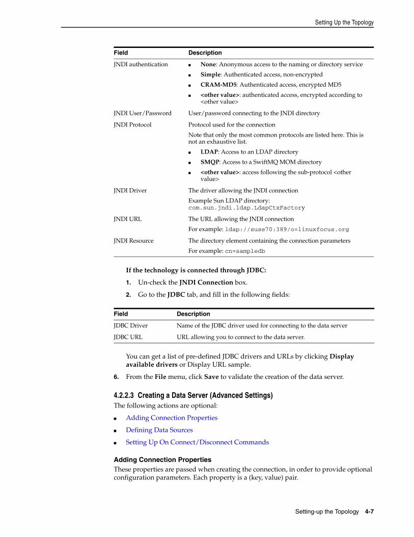
Setting Up the Topology
Setting-up the Topology 4-7
If the technology is connected through JDBC:
1. Un-check the JNDI Connection box.
2. Go to the JDBC tab, and fill in the following fields:
You can get a list of pre-defined JDBC drivers and URLs by clicking Display available drivers or Display URL sample.
6. From the File menu, click Save to validate the creation of the data server.
4.2.2.3 Creating a Data Server (Advanced Settings)The following actions are optional:
■ Adding Connection Properties
■ Defining Data Sources
■ Setting Up On Connect/Disconnect Commands
Adding Connection PropertiesThese properties are passed when creating the connection, in order to provide optional configuration parameters. Each property is a (key, value) pair.
Field Description
JNDI authentication ■ None: Anonymous access to the naming or directory service
■ Simple: Authenticated access, non-encrypted
■ CRAM-MD5: Authenticated access, encrypted MD5
■ <other value>: authenticated access, encrypted according to <other value>
JNDI User/Password User/password connecting to the JNDI directory
JNDI Protocol Protocol used for the connection
Note that only the most common protocols are listed here. This is not an exhaustive list.
■ LDAP: Access to an LDAP directory
■ SMQP: Access to a SwiftMQ MOM directory
■ <other value>: access following the sub-protocol <other value>
JNDI Driver The driver allowing the JNDI connection
Example Sun LDAP directory: com.sun.jndi.ldap.LdapCtxFactory
JNDI URL The URL allowing the JNDI connection
For example: ldap://suse70:389/o=linuxfocus.org
JNDI Resource The directory element containing the connection parameters
For example: cn=sampledb
Field Description
JDBC Driver Name of the JDBC driver used for connecting to the data server
JDBC URL URL allowing you to connect to the data server.
Setting Up the Topology
4-8 Oracle Fusion Middleware Developer's Guide for Oracle Data Integrator
■ For JDBC: These properties depend on the driver used. Please see the driver documentation for a list of available properties. It is possible in JDBC to specify here the user and password for the connection, instead of specifying there in the Definition tab.
■ For JNDI: These properties depend on the resource used.
To add a connection property to a data server:
1. On the Properties tab click Add a Property.
2. Specify a Key identifying this property. This key is case-sensitive.
3. Specify a value for the property.
4. From the File menu, click Save.
Defining Data Sources On the Data Sources tab you can define JDBC data sources that will be used by Oracle Data Integrator Java EE Agents deployed on application servers to connect to this data server. Note that data sources are not applicable for standalone agents.
Defining data sources is not mandatory, but allows the Java EE agent to benefit from the data sources and connection pooling features available on the application server. Connection pooling allows reusing connections across several sessions. If a data source is not declared for a given data server in a Java EE agent, this Java EE agent always connects the data server using direct JDBC connection, that is without using any of the application server data sources.
Before defining the data sources in Oracle Data Integrator, please note the following:
■ Datasources for WebLogic Server should be created with the Statement Cache Size parameter set to 0 in the Connection Pool configuration. Statement caching has a minor impact on data integration performances, and may lead to unexpected results such as data truncation with some JDBC drivers. Note that this concerns only data connections to the source and target data servers, not the repository connections.
■ If using Connection Pooling with datasources, it is recommended to avoid ALTER SESSION statements in procedures and Knowledge Modules. If a connection requires ALTER SESSION statements, it is recommended to disable connection pooling in the related datasources.
To define JDBC data sources for a data server:
1. On the DataSources tab of the Data Server editor click Add a DataSource
2. Select a physical Agent in the Agent field.
3. Enter the data source name in the JNDI Name field.
Note that this name must match the name of the data source in your application server.
4. Check JNDI Standard if you want to use the environment naming context (ENC).
When JNDI Standard is checked, Oracle Data Integrator automatically prefixes the data source name with the string java:comp/env/ to identify it in the application server’s JNDI directory.
Note that the JNDI Standard is not supported by Oracle WebLogic Server and for global data sources.
5. From the File menu, click Save.
Setting Up the Topology
Setting-up the Topology 4-9
After having defined a data source for a Java EE agent, you must create it in the application server into which the Java EE agent is deployed. There are several ways to create data sources in the application server, including:
■ Configure the data sources from the application server console. For more information, refer to your application server documentation.
■ Deploying Datasources from Oracle Data Integrator in WLS for an Agent
■ Deploying an Agent in a Java EE Application Server (Oracle WebLogic Server)
Setting Up On Connect/Disconnect CommandsOn the On Connect/Dicsonnect tab you can define SQL commands that will be executed when a connection to a data server defined in the physical architecture is created or closed.
The On Connect command is executed every time an ODI component, including ODI client components, connects to this data server.
The On Disconnect command is executed every time an ODI component, including ODI client components, disconnects from this data server.
These SQL commands are stored in the master repository along with the data server definition.
Before setting up commands On Connect/Disconnect, please note the following:
■ The On Connect/Disconnect commands are only supported by data servers with a technology type Database (JDBC).
■ The On Connect and Disconnet commands are executed even when using data sources. In this case, the commands are executedwhen taking and releasing the connection from the connection pool.
■ Substitution APIs are supported. Note that the design time tags <% are not supported. Only the execution time tags <? and <@ are supported.
■ Only global variables in substitution mode (#GLOBAL.<VAR_NAME> or #<VAR_NAME> ) are supported. See "Variable Scope" for more information. Note that the Expression editor only displays variables that are valid for the current data server.
■ The variables that are used in On Connect and Disconnet commands are only replaced at runtime, when the session starts. A command using variables will fail when testing the data server connection or performing a View Data operation on this data server. Make sure that these variables are declared in the scenarios.
■ Oracle Data Integrator Sequences are not supported in the On Connect and Disconnet commands.
The commands On Connect/Disconnect have the following usage:
■ When a session runs, it opens connections to data servers. every time a connection is opened on a data server that has a command On Connect defined, a task is created under a specific step called Command on Connect. This task is named after the data server to which the connection is established, the step and task that create the connection to this data server. It contains the code of the On Connect command.
■ When the session completes, it closes all connections to the data servers. Every time a connection is closed on a data server that has a command On Disonnect defined, a task is created under a specific step called Command on Disconnect. This task is named after the data server that is disconnected, the step and task that
Setting Up the Topology
4-10 Oracle Fusion Middleware Developer's Guide for Oracle Data Integrator
dropped the connection to this data server. It contains the code of the On Disconnect command.
■ When an operation is made in ODI Studio or ODI Console that requires a connection to the data server (such as View Data or Test Connection), the commands On Connect/Disconnect are also executed if the Client Transaction is selected for this command.
To set up On Connect/Disconnect commands:
1. On the On Connect/Disconnect tab of the Data Server editor, click Launch the Expression Editor in the On Connect section or in the On Disconnect section.
2. In the Expression Editor, enter the SQL command.
3. Click OK. The SQL command is displayed in the Command field.
4. Optionally, select Commit, if you want to commit the connection after executing the command. Note that if AutoCommit or Client Transaction is selected in the Execute On list, this value will be ignored.
5. Optionally, select Ignore Errors, if you want to ignore the exceptions encountered during the command execution. Note that if Ignore Errors is not selected, the calling operation will end in error status. A command with Ignore Error selected that fails during a session will appear as a task in a Warning state.
6. From the Log Level list, select the logging level (from 1 to 5) of the connect or disconnect command. At execution time, commands can be kept in the session log based on their log level. Default is 3.
7. From the Execute On list, select the transaction(s) on which you want to execute the command.
You can select Select All or Unselect All to select or unselect all transactions.
8. From the File menu, click Save.
You can now test the connection, see Section 4.2.2.4, "Testing a Data Server Connection" for more information.
Note: You can specify whether or not to show On Connect and Disconnect steps in Operator Navigator. If the user parameter Hide On Connect and Disconnect Steps is set to Yes, On Connect and Disconnect steps are not shown.
Note: The Expression Editor displays only the subsitution methods and keywords that are available for the technology of the data server. Note that global variables are only displayed if the connection to the work repository is available.
Note: Transactions from 0 to 9 and the Autocommit transaction correspond to connection created by sessions (by procedures or knowledge modules). The Client Transaction correspondsto the client components (ODI Console and Studio).
Setting Up the Topology
Setting-up the Topology 4-11
4.2.2.4 Testing a Data Server ConnectionIt is recommended to test the data server connection before proceeding in the topology definition.
To test a connection to a data server:
1. In Topology Navigator expand the Technologies node in the Physical Architecture accordion and then expand the technology containing your data server.
2. Double-click the data server you want to test. The Data Server Editor opens.
3. Click Test Connection.
The Test Connection dialog is displayed.
4. Select the agent that will carry out the test. Local (No Agent) indicates that the local station will attempt to connect.
5. Click Detail to obtain the characteristics and capacities of the database and JDBC driver.
6. Click Test to launch the test.
A window showing "connection successful!" is displayed if the test has worked; if not, an error window appears. Use the detail button in this error window to obtain more information about the cause of the connection failure.
4.2.3 Creating a Physical SchemaAn Oracle Data Integrator Physical Schema corresponds to a pair of Schemas:
■ A (Data) Schema, into which Oracle Data Integrator will look for the source and target data structures for the interfaces.
■ A Work Schema, into which Oracle Data Integrator can create and manipulate temporary work data structures associated to the sources and targets contained in the Data Schema.
Frequently used technologies have their physical schema creation methods detailed in the Oracle Fusion Middleware Connectivity and Knowledge Modules Guide for Oracle Data Integrator.
Before creating a Physical Schema, note the following:
■ Not all technologies support multiple schemas. In some technologies, you do not specify the work and data schemas since one data server has only one schema.
■ Some technologies do not support the creation of temporary structures. The work schema is useless for these technologies.
■ The user specified in the data server to which the Physical Schema is attached must have appropriate privileges on the schemas attached to this data server.
To create a Physical Schema:
1. Select the data server, Right-click and select New Physical Schema. The Physical Schema Editor appears.
2. If the technology supports multiple schemas:
a. Select or type the Data Schema for this Data Integrator physical schema in ... (Schema). A list of the schemas appears if the technologies supports schema listing.
Setting Up the Topology
4-12 Oracle Fusion Middleware Developer's Guide for Oracle Data Integrator
b. Select or type the Work Schema for this Data Integrator physical schema in ... (Work Schema). A list of the schemas appears if the technologies supports schema listing.
3. Check the Default box if you want this schema to be the default one for this data server (The first physical schema is always the default one).
4. Go to the Context tab.
5. Click Add.
6. Select a Context and an existing Logical Schema for this new Physical Schema.
If no Logical Schema for this technology exists yet, you can create it from this Editor.
To create a Logical Schema:
1. Select an existing Context in the left column.
2. Type the name of a Logical Schema in the right column.
This Logical Schema is automatically created and associated to this physical schema in this context when saving this Editor.
7. From the File menu, click Save.
4.2.4 Creating a Logical SchemaTo create a logical schema:
1. In Topology Navigator expand the Technologies node in the Logical Architecture accordion.
2. Select the technology you want to attach your logical schema to.
3. Right-click and select New Logical Schema.
4. Fill in the schema name.
5. For each Context in the left column, select an existing Physical Schema in the right column. This Physical Schema is automatically associated to the logical schema in this context. Repeat this operation for all necessary contexts.
6. From the File menu, click Save.
4.2.5 Creating a Physical AgentTo create a Physical Agent:
1. In Topology Navigator right-click the Agents node in the Physical Architecture accordion.
2. Select New Agent.
3. Fill in the following fields:
■ Name: Name of the agent used in the Java graphical interface.
■ Host: Network name or IP address of the machine the agent will been launched on.
■ Port: Listening port used by the agent. By default, this port is the 20910.
■ Web Application Context: Name of the web application corresponding to the Java EE agent deployed on an application server. For standalone agents, this field should be set to oraclediagent.
Managing Agents
Setting-up the Topology 4-13
■ Protocol: Protocol to use for the agent connection. Possible values are http or https. Default is http.
■ Maximum number of sessions supported by this agent.
4. If you want to setup load balancing, go to the Load balancing tab and select a set of linked physical agent to which the current agent can delegate executions. See Section 4.3.3.3, "Setting Up Load Balancing" for more information.
5. If the agent is launched, click Test. The successful connection dialog is displayed.
6. Click Yes.
4.2.6 Creating a Logical AgentTo create a logical agent:
1. In Topology Navigator right-click the Agents node in the Logical Architecture accordion.
2. Select New Logical Agent.
3. Fill in the Agent Name.
4. For each Context in the left column, select an existing Physical Agent in the right column. This Physical Agent is automatically associated to the logical agent in this context. Repeat this operation for all necessary contexts.
5. From the File menu, click Save.
4.3 Managing AgentsThis section describes how to work with a standalone agent, a Java EE agent and how to handle load balancing.
4.3.1 Standalone AgentManaging the standalone agent involves the actions discussed in these sections:
■ Section 4.3.1.1, "Configuring the Standalone Agent"
■ Section 4.3.1.2, "Launching a Standalone Agent"
■ Section 4.3.1.3, "Stopping an Agent"
4.3.1.1 Configuring the Standalone Agent The odiparams file is a configuration script that contains the parameters for the Oracle Data Integrator standalone agent command line scripts. It contains the repository connection and credential information for starting the standalone agent. It is necessary to have this configuration done before starting a standalone agent.
This file is in the /agent/bin directory of the Oracle Data Integrator installation directory.
Note: The agent command line scripts, which are required for performing the tasks described in this section, are only available if you have installed the Oracle Data Integrator Standalone Agent. See the Oracle Fusion Middleware Installation Guide for Oracle Data Integrator for information about how to install the Standalone Agent.
Managing Agents
4-14 Oracle Fusion Middleware Developer's Guide for Oracle Data Integrator
■ On UNIX system:
odiparams.sh
■ On Windows system:
odiparams.bat
This file can be edited with a text editor to set the configuration parameters.
See Table 4–1 for the list of these parameters.
Note: The odiparams file is preconfigured if you have installed your standalone agent using Oracle Universal Installer and have selected to configure a repository connection during installation.
Table 4–1 Repository Connection Information
Parameter Description
ODI_MASTER_DRIVER JDBC driver used to connect the master repository.
ODI_MASTER_URL JDBC URL used to connect the master repository. This URL must be quoted if it contains one of the following characters:
■ semicolon (;)
■ backslash (\)
■ double quote (")
■ back quote (`)
■ dollar sign ($)
■ less than (<)
■ greater then (>)
ODI_MASTER_USER Database account used to connect the master repository
ODI_MASTER_ENCODED_PASS Database account password. The password must be encoded with the encode.[sh|bat] <password> command.
ODI_SECU_WORK_REP Name of the work repository to connect to. This work repository is the default repository into which the scenarios are started. See Chapter 20, "Running Integration Processes" for more information.
ODI_SUPERVISOR Name of an ODI SUPERVISOR user. This SUPERVISOR user is used by the agent to connect the master repository.
ODI_SUPERVISOR_ENCODED_PASS This SUPERVISOR user’s password. The password must be encoded with the encode.[sh|bat] <password> command.
ODI_USER Name of an ODI user used to start scenarios. This user’s credentials are used when starting a scenario from a command line. See Chapter 20, "Running Integration Processes" for more information.
ODI_ENCODED_PASS This ODI user password
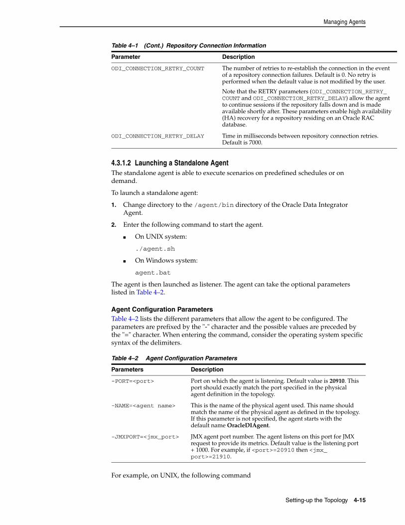
Managing Agents
Setting-up the Topology 4-15
4.3.1.2 Launching a Standalone AgentThe standalone agent is able to execute scenarios on predefined schedules or on demand.
To launch a standalone agent:
1. Change directory to the /agent/bin directory of the Oracle Data Integrator Agent.
2. Enter the following command to start the agent.
■ On UNIX system:
./agent.sh
■ On Windows system:
agent.bat
The agent is then launched as listener. The agent can take the optional parameters listed in Table 4–2.
Agent Configuration ParametersTable 4–2 lists the different parameters that allow the agent to be configured. The parameters are prefixed by the "-" character and the possible values are preceded by the "=" character. When entering the command, consider the operating system specific syntax of the delimiters.
For example, on UNIX, the following command
ODI_CONNECTION_RETRY_COUNT The number of retries to re-establish the connection in the event of a repository connection failures. Default is 0. No retry is performed when the default value is not modified by the user.
Note that the RETRY parameters (ODI_CONNECTION_RETRY_COUNT and ODI_CONNECTION_RETRY_DELAY) allow the agent to continue sessions if the repository falls down and is made available shortly after. These parameters enable high availability (HA) recovery for a repository residing on an Oracle RAC database.
ODI_CONNECTION_RETRY_DELAY Time in milliseconds between repository connection retries. Default is 7000.
Table 4–2 Agent Configuration Parameters
Parameters Description
-PORT=<port> Port on which the agent is listening. Default value is 20910. This port should exactly match the port specified in the physical agent definition in the topology.
-NAME=<agent name> This is the name of the physical agent used. This name should match the name of the physical agent as defined in the topology. If this parameter is not specified, the agent starts with the default name OracleDIAgent.
-JMXPORT=<jmx_port> JMX agent port number. The agent listens on this port for JMX request to provide its metrics. Default value is the listening port + 1000. For example, if <port>=20910 then <jmx_port>=21910.
Table 4–1 (Cont.) Repository Connection Information
Parameter Description
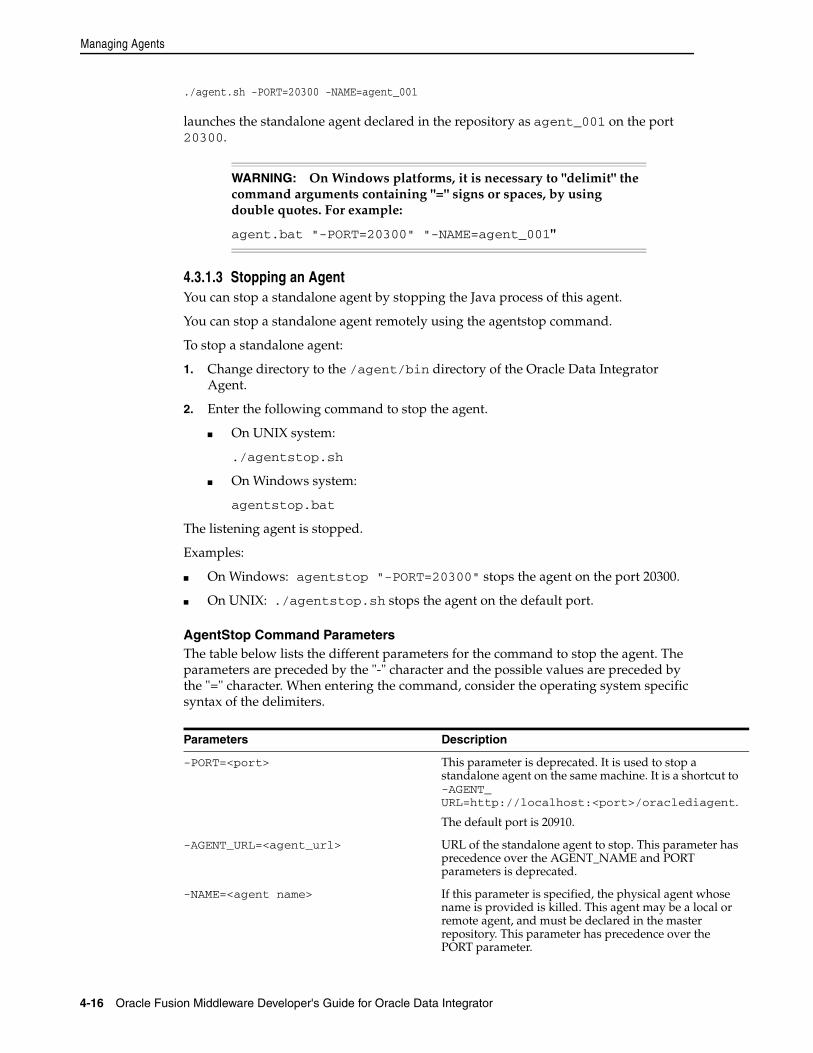
Managing Agents
4-16 Oracle Fusion Middleware Developer's Guide for Oracle Data Integrator
./agent.sh -PORT=20300 -NAME=agent_001
launches the standalone agent declared in the repository as agent_001 on the port 20300.
4.3.1.3 Stopping an AgentYou can stop a standalone agent by stopping the Java process of this agent.
You can stop a standalone agent remotely using the agentstop command.
To stop a standalone agent:
1. Change directory to the /agent/bin directory of the Oracle Data Integrator Agent.
2. Enter the following command to stop the agent.
■ On UNIX system:
./agentstop.sh
■ On Windows system:
agentstop.bat
The listening agent is stopped.
Examples:
■ On Windows: agentstop "-PORT=20300" stops the agent on the port 20300.
■ On UNIX: ./agentstop.sh stops the agent on the default port.
AgentStop Command ParametersThe table below lists the different parameters for the command to stop the agent. The parameters are preceded by the "-" character and the possible values are preceded by the "=" character. When entering the command, consider the operating system specific syntax of the delimiters.
WARNING: On Windows platforms, it is necessary to "delimit" the command arguments containing "=" signs or spaces, by using double quotes. For example:
agent.bat "-PORT=20300" "-NAME=agent_001"
Parameters Description
-PORT=<port> This parameter is deprecated. It is used to stop a standalone agent on the same machine. It is a shortcut to -AGENT_URL=http://localhost:<port>/oraclediagent.
The default port is 20910.
-AGENT_URL=<agent_url> URL of the standalone agent to stop. This parameter has precedence over the AGENT_NAME and PORT parameters is deprecated.
-NAME=<agent name> If this parameter is specified, the physical agent whose name is provided is killed. This agent may be a local or remote agent, and must be declared in the master repository. This parameter has precedence over the PORT parameter.
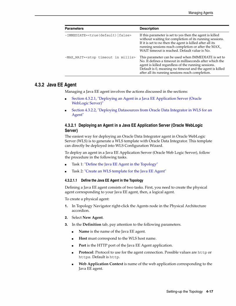
Managing Agents
Setting-up the Topology 4-17
4.3.2 Java EE AgentManaging a Java EE agent involves the actions discussed in the sections:
■ Section 4.3.2.1, "Deploying an Agent in a Java EE Application Server (Oracle WebLogic Server)"
■ Section 4.3.2.2, "Deploying Datasources from Oracle Data Integrator in WLS for an Agent"
4.3.2.1 Deploying an Agent in a Java EE Application Server (Oracle WebLogic Server)The easiest way for deploying an Oracle Data Integrator agent in Oracle WebLogic Server (WLS) is to generate a WLS template with Oracle Data Integrator. This template can directly be deployed into WLS Configuration Wizard.
To deploy an agent in a Java EE Application Server (Oracle Web Logic Server), follow the procedure in the following tasks.
■ Task 1: "Define the Java EE Agent in the Topology"
■ Task 2: "Create an WLS template for the Java EE Agent"
4.3.2.1.1 Define the Java EE Agent in the Topology
Defining a Java EE agent consists of two tasks. First, you need to create the physical agent corresponding to your Java EE agent, then, a logical agent.
To create a physical agent:
1. In Topology Navigator right-click the Agents node in the Physical Architecture accordion.
2. Select New Agent.
3. In the Definition tab, pay attention to the following parameters.
■ Name is the name of the Java EE agent.
■ Host must correspond to the WLS host name.
■ Port is the HTTP port of the Java EE Agent application.
■ Protocol: Protocol to use for the agent connection. Possible values are http or https. Default is http.
■ Web Application Context is name of the web application corresponding to the Java EE agent.
-IMMEDIATE=<true(default)|false> If this parameter is set to yes then the agent is killed without waiting for completion of its running sessions. If it is set to no then the agent is killed after all its running sessions reach completion or after the MAX_WAIT timeout is reached. Default value is No.
-MAX_WAIT=<stop timeout in millis> This parameter can be used when IMMEDIATE is set to No. It defines a timeout in milliseconds after which the agent is killed regardless of the running sessions. Default is 0, meaning no timeout and the agent is killed after all its running sessions reach completion.
Parameters Description
Managing Agents
4-18 Oracle Fusion Middleware Developer's Guide for Oracle Data Integrator
4. Drag and drop the work repositories or data servers to be managed as Java EE data sources from the Repositories accordion in the Topology Navigator into the DataSources tab of this agent's Editor.
5. Provide a JNDI name for these data sources.
6. Drag and drop the source/target data servers that this agent will access from the Physical Architecture accordion in the Topology Navigator into the DataSources tab of this agent's Editor.
7. Provide a JNDI name for these data sources.
8. From the File menu, click Save to save the Physical Agent.
To create a logical agent:
1. Create a Logical Agent for this Physical Agent as described in Section 4.2.6, "Creating a Logical Agent".
2. Map the Logical Agent in the appropriate context.
4.3.2.1.2 Create an WLS template for the Java EE Agent
Oracle Data Integrator provides a WLS Template Generation wizard to help you create an WLS template for a run-time agent.
To open the WLS Template Generation wizard:
1. From the Physical Agent Editor toolbar menu, select Generate WLS Template. This starts the Template Generation wizard.
2. In the Agent Information step, review the agent information and modify the default configuration if needed.
The Agent Information includes the following parameters:
■ General
Agent Name: Displays the name of the Agent that you want to deploy.
■ Master Repository Connection
JNDI Datasource Name: The name of the datasource used by the Java EE agent to connect to the master repository. The template can contain a definition of this datasource. Default is jdbc/odiMasterRepository.
■ Connection Retry Settings
Connection Retry Count: Number of retry attempts done if the agent loses the connection to the repository. Note that setting this parameter to a non-zero value, enables a high availability connection retry feature if the ODI repository resides on an Oracle RAC database. If this feature is enabled, the agent can continue to execute sessions without interruptions even if one or more Oracle RAC nodes become unavailable.
Retry Delay (milliseconds): Interval (in milliseconds) between each connection retry attempt.
■ Supervisor Authentication
Supervisor Key: Name of the key in the application server credential store that contains the login and the password of an ODI user with Supervisor privileges. This agent will use this user credentials to connect to the repository.
3. Click Next.
Managing Agents
Setting-up the Topology 4-19
4. In the Libraries and Drivers step, select from the list the external libraries and drivers to deploy with this agent. Only libraries added by the user appear here.
Note that the libraries can be any JAR or ZIP file that is required for this agent. Additional JDBC drivers or libraries for accessing the source and target data servers must be selected here.
You can use the corresponding buttons in the toolbar to select or deselect all libraries and/or drivers in the list.
5. Click Next.
6. In the Datasources step, select the datasources definitions that you want to include in this agent template. You can only select datasources from the wizard. Naming and adding these datasources is done in the Data Sources tab of the Physical Agent editor.
7. Click Next.
8. In Template Target and Summary step, enter the Target Template Path where the WLS template will be generated.
9. Click Finish to close the wizard and generate the WLS template.
The Template generation information dialog appears.
10. Click OK to close the dialog.
The generated template can be used to deploy the agent in WLS using the WLS configuration wizard. Refer to the Oracle Fusion Middleware Installation Guide for Oracle Data Integrator for more information.
Declare the Supervisor in the WLS Credential StoreAfter deploying the template, it is necessary to declare the Supervisor into the WLS Credential Store. Refer to the Oracle Fusion Middleware Installation Guide for Oracle Data Integrator for more information.
4.3.2.2 Deploying Datasources from Oracle Data Integrator in WLS for an AgentYou can create datasources from the Topology Navigator into a WebLogic Server for which a Java EE agent is configured.
To deploy datasources in a Oracle WebLogic Server:
1. Open the Physical Agent Editor configured for the WLS application server into which you want to deploy the datasources.
2. Go to the Datasources tab.
3. Drag and Drop the source/target data servers from the Physical Architecture tree in the Topology Navigator into the DataSources tab.
4. Provide a JNDI Name for these datasources.
5. Right-click any of the datasource, then select Deploy Datasource on WLS.
6. Fill in the following fields:
■ Host: Host name or IP address of the WLS Admin Server.
■ Port: Port of the WLS Admin Server
■ User: WebLogic server user name.
■ Password: this user’s password
Managing Agents
4-20 Oracle Fusion Middleware Developer's Guide for Oracle Data Integrator
■ Target: WLS Target into which this datasource will be deployed.
7. Click OK.
WLS Datasource Configuration and UsageWhen setting up datasources in WebLogic Server for Oracle Data Integrator, please note the following:
■ Datasources should be created with the Statement Cache Size parameter set to 0 in the Connection Pool configuration. Statement caching has a minor impact on data integration performances, and may lead to unexpected results such as data truncation with some JDBC drivers.
■ If using Connection Pooling with datasources, it is recommended to avoid ALTER SESSION statements in procedures and Knowledge Modules. If a connection requires ALTER SESSION statements, it is recommended to disable connection pooling in the related datasources, as an altered connection returns to the connection pool after usage.
4.3.3 Load Balancing AgentsOracle Data Integrator allows to load balance parallel session execution between physical agents.
Each physical agent is defined with:
■ A maximum number of sessions it can execute simultaneously from a work repository
The maximum number of sessions is a value that must be set depending on the capabilities of the machine running the agent. It can be also set depending on the amount of processing power you want to give to the Oracle Data Integrator agent.
■ Optionally, a number of linked physical agents to which it can delegate sessions' executions.
An agent's load is determined at a given time by the ratio (Number of running sessions / Maximum number of sessions) for this agent.
4.3.3.1 Delegating SessionsWhen a session is started on an agent with linked agents, Oracle Data Integrator determines which one of the linked agents is less loaded, and the session is delegated to this linked agent.
An agent can be linked to itself, in order to execute some of the incoming sessions, instead of delegating them all to other agents. Note that an agent not linked to itself is only able to delegate sessions to its linked agents, and will never execute a session.
Delegation cascades in the hierarchy of linked agents. If agent A has agent B1 and B2 linked to it, and agent B1 has agent C1 linked to it, then sessions started on agent A
Note: This operation only creates the Datasources definition in WebLogic Server. It does not install drivers or library files needed for these datasources to work. Additional drivers added to the Studio classpath can be included into a WLS Agent Template. See Section 4.3.2.1.2, "Create an WLS template for the Java EE Agent" for more information.
Managing Agents
Setting-up the Topology 4-21
will be executed by agent B2 or agent C1. Note that it is not recommended to make loops in agents links.
If the user parameter "Use new Load Balancing" is set to Yes, sessions are also re-balanced each time a session finishes. This means that if an agent runs out of sessions, it will possibly be reallocated sessions already allocated to another agent.
4.3.3.2 Agent UnavailableWhen for a given agent the number of running sessions reaches its maximum number of sessions, the agent will put incoming sessions in a "queued" status until the number of running sessions falls below the maximum of sessions.
If an agent is unavailable (because it crashed for example), all its sessions in queue will be re-assigned to another load balanced agent that is neither running any session nor having sessions in queue if the user parameter Use the new load balancing is set to Yes. See Appendix B, "User Parameters" for more information.
4.3.3.3 Setting Up Load BalancingTo setup load balancing:
1. Define a set of physical agents, and link them in a hierarchy of agents (See "Creating a Physical Agent" for more information.)
2. Start all the physical agents corresponding to the agents defined in the topology.
3. Run the executions on the root agent of your hierarchy. Oracle Data Integrator will balance the load of the executions between its linked agents.

Managing Agents
4-22 Oracle Fusion Middleware Developer's Guide for Oracle Data Integrator
Part IIIPart III Managing and Reverse-Engineering
Metadata
This part describes how to manage and reverse-engineer metadata in Oracle Data Integrator.
This part contains the following chapters:
■ Chapter 5, "Creating and Reverse-Engineering a Model"
■ Chapter 6, "Working with Common Format Designer"
■ Chapter 7, "Working with Changed Data Capture"
■ Chapter 8, "Working with Data Services"

5
Creating and Reverse-Engineering a Model 5-1
5Creating and Reverse-Engineering a Model
This chapter describes how to create a model, how to reverse-engineer this model to populate it with datastores and how to create manually datastores of a model. This chapter also explains how to use partitioning and check the quality of the data in a model.
This chapter includes the following sections:
■ Section 5.1, "Introduction to Models"
■ Section 5.2, "Creating and Reverse-Engineering a Model"
■ Section 5.3, "Creating and Reverse-Engineering a Datastore"
■ Section 5.4, "Editing and Viewing a Datastore's Data"
■ Section 5.5, "Using Partitioning"
■ Section 5.6, "Checking Data Quality in a Model"
5.1 Introduction to ModelsA Model is the description of a set of datastores. It corresponds to a group of tabular data structures stored in a data server. A model is based on a Logical Schema defined in the topology. In a given Context, this Logical Schema is mapped to a Physical Schema. The Data Schema of this Physical Schema contains physical data structure: tables, files, JMS messages, elements from an XML file, that are represented as datastores.
Models as well as all their components are based on the relational paradigm (table, columns, keys, etc.). Models in Data Integrator only contain Metadata, that is the description of the data structures. They do not contain a copy of the actual data.
Models can be organized into model folders and the datastores of a model can be organized into sub-models. Section 17.2, "Organizing Models with Folders" describes how to create and organize model folders and sub-models.
5.1.1 DatastoresA datastore represents a data structure. It can be a table, a flat file, a message queue or any other data structure accessible by Oracle Data Integrator.
Note: Frequently used technologies have their reverse and model creation methods detailed in the Oracle Fusion Middleware Connectivity and Knowledge Modules Guide for Oracle Data Integrator.
Introduction to Models
5-2 Oracle Fusion Middleware Developer's Guide for Oracle Data Integrator
A datastore describes data in a tabular structure. Datastores are composed of columns.
As datastores are based on the relational paradigm, it is also possible to associate the following elements to a datastore:
■ Keys
A Key is a set of columns with a specific role in the relational paradigm. Primary and Alternate Keys identify each record uniquely. Non-Unique Indexes enable optimized record access.
■ References
A Reference is a functional link between two datastores. It corresponds to a Foreign Key in a relational model. For example: The INVOICE datastore references the CUSTOMER datastore through the customer number.
■ Conditions and Filters
Conditions and Filters are a WHERE-type SQL expressions attached to a datastore. They are used to validate or filter the data in this datastore.
5.1.2 Data IntegrityA model contains constraints such as Keys, References or Conditions, but also non-null flags on columns. Oracle Data Integrator includes a data integrity framework for ensuring the quality of a data model.
This framework allows to perform:
■ Static Checks to verify the integrity of the data contained in a data model. This operation is performed to assess the quality of the data in a model when constraints do not physically exist in the data server but are defined in Data Integrator only.
■ Flow Check to verify the integrity of a data flow before it is integrated into a given datastore. The data flow is checked against the constraints defined in Oracle Data Integrator for the datastore that is the target of the data flow.
5.1.3 Reverse-engineeringA new model is created with no datastores. Reverse-engineering is the process that populates the model in Oracle Data Integrator by retrieving metadata from the data server containing the data structures. There are two different types of reverse-engineering:
■ Standard reverse-engineering uses standard JDBC driver features to retrieve the metadata.
■ Customized reverse-engineering uses a technology-specific Reverse Knowledge Module (RKM) to retrieve the metadata, using a method specific to the given technology. This method usually retrieves more information than the Standard reverse-engineering method.
Other methods for reverse-engineering exist for flat file datastores. They are detailed in the Reverse-Engineering File Datastores section.
5.1.4 Changed Data CaptureChange Data Capture (CDC), also referred to as Journalizing, allows to trap changes occurring on the data. CDC is used in Oracle Data Integrator to eliminate the transfer
Creating and Reverse-Engineering a Model
Creating and Reverse-Engineering a Model 5-3
of unchanged data. This feature can be used for example for data synchronization and replication.
Journalizing can be applied to models, sub-models or datastores based on certain type of technologies.
For information about setting up Changed Data Capture, see Chapter 7, "Working with Changed Data Capture".
5.2 Creating and Reverse-Engineering a ModelNow that the key components of an ODI model have been described, an overview is provided on how to create and reverse-engineer a model.
5.2.1 Creating a ModelA Model is a set of datastores corresponding to data structures contained in a Physical Schema.
To create a Model:
1. In Designer Navigator expand the Models panel.
2. Right-click then select New Model.
3. Fill in the following fields in the Definition tab:
■ Name: Name of the model used in the user interface.
■ Technology: Select the model's technology.
■ Logical Schema: Select the Logical Schema on which your model will be based.
4. Go to the Reverse tab, and select a Context which will be used for the model's reverse-engineering.
Note that if there is only one context that maps the logical schema, this context will be set automatically.
5. Select Save from the File main menu.
The model is created, but contains no datastore yet.
5.2.2 Reverse-engineering a ModelTo automatically populate datastores into the model you need to perform a reverse-engineering for this model.
Standard Reverse-Engineering A Standard Reverse-Engineering uses the capacities of the JDBC driver used to connect the data server to retrieve the model metadata.
To perform a Standard Reverse- Engineering:
1. In the Reverse tab of your Model:
■ Select Standard.
■ Select the Context used for the reverse-engineering
■ Select the Types of objects to reverse-engineer. Only object of these types will be taken into account by the reverse-engineering process.
Creating and Reverse-Engineering a Model
5-4 Oracle Fusion Middleware Developer's Guide for Oracle Data Integrator
■ Enter in the Mask field the mask of tables to reverse engineer. The mask selects the objects to reverse. This mask uses the SQL LIKE syntax. The percent (%) symbol means zero or more characters, and the underscore (_) symbol means one character.
■ Optionally, you can specify the characters to remove for the table alias. These are the characters to delete in order to derive the alias. Note that if the datastores already exist, the characters specified here will not be removed from the table alias. Updating a datastore is not applied to the table alias.
2. In the Selective Reverse tab select Selective Reverse, New Datastores, Existing Datastores and Objects to Reverse.
3. A list of datastores to be reverse-engineered appears. Leave those you wish to reverse-engineer checked.
4. Select Save from the File main menu.
5. Click Reverse Engineer in the Model toolbar menu.
6. Oracle Data Integrator launches a reverse-engineering process for the selected datastores. A progress bar indicates the progress of the reverse-engineering process.
The reverse-engineered datastores appear under the model node in the Models panel.
Customized Reverse-EngineeringA Customized Reverse-Engineering uses a Reverse-engineering Knowledge Module (RKM), to retrieve metadata for a specific type of technology and create the corresponding datastore definition in the data model.
For example, for the Oracle technology, the RKM Oracle accesses the database dictionary tables to retrieve the definition of tables, columns, keys, etc, that are created in the model.
To perform a Customized Reverse-Engineering using a RKM:
1. In the Reverse tab of your Model:
■ Select Customized.
■ Select the Context used for the reverse-engineering
■ Select the Types of objects to reverse-engineer. Only object of these types will be taken into account by the reverse-engineering process.
■ Enter in the Mask the mask of tables to reverse engineer.
■ Select the KM that you want to use for performing the reverse-engineering process. This KM is typically called RKM <technology>.<name of the project>.
■ Optionally, you can specify the characters to remove for the table alias. These are the characters to delete in order to derive the alias. Note that if the datastores already exist, the characters specified here will not be removed from the table alias. Updating a datastore is not applied to the table alias.
Note: Using a RKM requires that you import this RKM into a project. Refer to Chapter 9, "Creating an Integration Project" for more information on KM import.
Creating and Reverse-Engineering a Datastore
Creating and Reverse-Engineering a Model 5-5
2. Click Reverse Engineer in the Model toolbar menu, then Yes to validate the changes.
3. Click OK.
4. The Session Started Window appears.
5. Click OK.
You can review the reverse-engineering tasks in the Operator Navigator. If the reverse-engineering process completes correctly, reverse-engineered datastores appear under the model node in the Models panel.
5.3 Creating and Reverse-Engineering a DatastoreAlthough the recommended method for creating datastores in a model is reverse-engineering, it is possible to manually define datastores in a blank model. It is the recommended path for creating flat file datastores.
5.3.1 Creating a DatastoreTo create a datastore:
1. From the Models tree in Designer Navigator, select a Model or a Sub-Model.
2. Right-click and select New Datastore.
3. In the Definition tab, fill in the following fields:
■ Name of the Datastore: This is the name that appears in the trees and that is used to reference the datastore from a project
■ Resource Name: Name of the object in the form recognized by the data server which stores it. This may be a table name, a file name, the name of a JMS Queue, etc.
■ Alias: This is a default alias used to prefix this datastore’s columns names in expressions.
4. If the datastore represents a flat file (delimited or fixed), in the File tab, fill in the following fields:
■ File Format: Select the type of your flat file, fixed or delimited.
■ Header: Number of header lines for the flat file.
■ Record Separator and Field Separator define the characters used to separate records (lines) in the file, and fields within one record.
Record Separator: One or several characters separating lines (or records) in the file:
– MS-DOS: DOS carriage return
– Unix: UNIX carriage return
– Other: Free text you can input as characters or hexadecimal codes
Field Separator: One ore several characters separating the fields in a record.
– Tabulation
– Space
– Other: Free text you can input as characters or hexadecimal code
Creating and Reverse-Engineering a Datastore
5-6 Oracle Fusion Middleware Developer's Guide for Oracle Data Integrator
5. Select Save from the File main menu.
The datastore is created. If this is a File datastore, refer to the Reverse-Engineering File Datastores section for creating columns for this datastore. It is also possible to manually edit columns for all datastores. See Adding and Deleting Datastore Columns for more information.
5.3.2 Reverse-Engineering File DatastoresOracle Data Integrator provides specific methods for reverse-engineering flat files. The methods for reversing flat files are described below.
5.3.2.1 Reverse-Engineering Fixed FilesFixed files can be reversed engineered using a wizard into which the boundaries of the fixed columns and their parameters can be defined.
1. Go to the Columns tab the file datastore that has a fixed format.
2. Click the Reverse button. A window opens displaying the first records of your file.
3. Click on the ruler (above the file contents) to create markers delimiting the columns. Right-click in the ruler to delete a marker.
4. Columns are created with pre-generated names (C1, C2, and so on). You can edit the column name by clicking in the column header line (below the ruler).
5. In the properties panel (on the right), you can edit the parameters of the selected column.
6. You must set at least the Column Name, Datatype and Length for each column. Note that column names of File datastores cannot contain spaces.
7. Click OK when the columns definition is complete to close the wizard.
8. Select Save from the File main menu.
5.3.2.2 Reverse-Engineering Delimited FilesDelimited files can be reversed engineered using a a built-in JDBC which analyzes the file to detect the columns and reads the column names from the file header.
1. Go to the Columns tab the file datastore that has a delimited format.
2. Click the Reverse button.
3. Oracle Data Integrator creates the list of columns according to your file content. The column type and length are set to default values. Column names are pre-generated names (C1, C2, and so on) or names taken from the first Header line declared for this file.
4. Review and if needed modify the Column Name, Datatype and Length for each column. Note that column names of File datastores cannot contain spaces.
5. Select Save from the File main menu.
5.3.2.3 Reverse-Engineering COBOL FilesFixed COBOL files structures are frequently described in Copybook files. Oracle Data Integrator can reverse-engineer the Copybook file structure into a datastore structure.
1. Go to the Columns tab the file datastore that has a delimited format.
2. Click the Reverse COBOL Copybook button.
Creating and Reverse-Engineering a Datastore
Creating and Reverse-Engineering a Model 5-7
3. Fill in the following fields:
■ File: Location of the Copybook file.
■ Character Set: Copybook file character set.
■ Description format (EBCDIC or ASCII): Copybook file format
■ Data format (EBCDIC or ASCII): Data file format.
4. Click OK. The columns described in the Copybook are reverse-engineered and appear in the column list.
5. Select Save from the File main menu.
5.3.3 Adding and Deleting Datastore Columns To add columns to a datastore:
1. In the Columns tab of the datastore, click Add Column in the toolbar menu.
2. An empty line appears. Fill in the information about the new column. You should at least fill in the Name, Datatype and Length fields.
3. Repeat steps 1 and 2 for each column you want to add to the datastore.
4. Select Save from the File main menu.
To delete columns from a datastore:
1. In the Columns tab of the datastore, select the column to delete.
2. Click the Delete Column button. The column disappears from the list.
5.3.4 Adding and Deleting Constraints and FiltersOracle Data Integrator manages constraints on data model including Keys, References, Conditions and Mandatory Columns. It includes a data integrity framework for ensuring the quality of a data model based on these constraints.
Filters are not constraints but are defined similarly to Conditions. A Filter is not used to enforce a data quality rule on a datastore, but is used to automatically filter this datastore when using it as a source.
5.3.4.1 KeysTo create a key for a datastore:
1. In the Designer Navigator, expand in the Model tree the model and then the datastore into which you want to add the key.
2. Select the Constraints node, right-click and select New Key.
3. Enter the Name for the constraint, and then select the Key or Index Type. Primary Keys and Alternate Keys can be checked and can act as an update key in an interface. Non-Unique Index are used mainly for performance reasons.
4. In the Columns tab, select the list of columns that belong to this key.
5. In the Control tab, select whether this constraint should be checked by default in a Static or Flow check.
6. By clicking the Check button, you can retrieve the number of records that do not respect this constraint.
7. Select Save from the File main menu.
Creating and Reverse-Engineering a Datastore
5-8 Oracle Fusion Middleware Developer's Guide for Oracle Data Integrator
5.3.4.2 ReferencesTo create a reference between two datastores:
1. In the Designer Navigator, expand in the Model tree the model and then one of the datastores into which you want to add the reference.
2. Select the Constraints node, right-click and select New Reference.
3. Enter the Name for the constraint, and then select the Type for the reference. In a User Reference the two datastores are linked based on column equality. In a Complex User Reference any expression can be used to link the two datastores. A Database Reference is a reference based on column equality that has been reverse-engineered from a database engine.
4. If you want to reference a datastore that exists in a model, select the Model and the Table that you want to link to the current datastore.
5. If you want to link a table that does not exist in a model, leave the Model and Table fields undefined, and set the Catalog, Schema and Table names to identify your datastore.
6. If you are defining a User or Database reference, in the Columns tab, define the matching columns from the two linked datastores.
7. If you are defining a Complex User reference, enter in the Expression tab the expression that relates columns from the two linked datastores.
8. In the Control tab, select whether this constraint should be checked by default in a Static or Flow check.
9. By clicking the Check button, you can retrieve the number of records that respect or do not respect this constraint.
10. Select Save from the File main menu.
5.3.4.3 Conditions To create a condition for a datastore:
1. In the Designer Navigator, expand in the Model tree the model and then one of the datastores into which you want to add the condition.
2. Select the Constraints node, right-click and select New Condition.
3. Enter the Name for the constraint, and then select the Type for the condition. An Oracle Data Integrator Condition is a condition that exists only in the model and does not exist in the database. A Database Condition is a condition that is defined in the database and has been reverse-engineered.
4. In the Where field enter the expression that implements the condition. This expression is a SQL WHERE expression that valid records should respect.
5. Type in the Message field the error message for this constraint.
6. In the Control tab, select whether this constraint should be checked by default in a Static or Flow check.
7. By clicking the Check button, you can retrieve the number of records that do not respect this constraint.
8. Select Save from the File main menu.
5.3.4.4 Mandatory Columns To define mandatory columns for a datastore:
Using Partitioning
Creating and Reverse-Engineering a Model 5-9
1. In the Designer Navigator, expand in the Model tree the model containing the datastores.
2. Double-click the datastore containing the column that must be set as mandatory. The Datastore Editor appears.
3. In the Columns tab, check the Not Null field for each column that is mandatory.
4. Select Save from the File main menu.
5.3.4.5 Filter To add a filter to a datastore:
1. In the Designer Navigator, expand in the Model tree the model and then one of the datastores into which you want to add the filter.
2. Select the Filter node, right-click and select New Condition.
3. Enter the Name for the filter.
4. In the Where field enter the expression that implements the filter. This expression is a SQL WHERE expression used to filter source records.
5. In the Control tab, check Filter Active for Static Control if you want data from this table to be filtered prior to checking it a static control.
6. Select Save from the File main menu.
5.4 Editing and Viewing a Datastore's DataTo view a datastore's data:
1. Select the datastore from the model in the Designer Navigator.
2. Right-click and select View Data.
The data appear in a non editable grid.
To edit a datastore's data:
1. Select the datastore from the model in the Designer Navigator.
2. Right-click and select Data...
The data appear in an editable grid in the Data Editor. The Refresh button enables you to edit and run again the query returning the datastore data. You can filter the data and perform free queries on the datastore using this method.
It is possible to edit a datastore's data if the connectivity used and the data server user's privileges allow it, and if the datastore structure enables to identify each row of the datastore (PK, etc.).
5.5 Using PartitioningOracle Data Integrator is able to use database-defined partitions when processing data in partitioned tables used as source or targets of integration interfaces. These partitions are created in the datastore corresponding to the table, either through the
Note: The data displayed is the data stored in the physical schema corresponding to the model's logical schema, in the current working context.
Checking Data Quality in a Model
5-10 Oracle Fusion Middleware Developer's Guide for Oracle Data Integrator
reverse-engineering process or manually. For example with the Oracle technology, partitions are reverse-engineered using the RKM Oracle.
The partitioning methods supported depend on the technology of the datastore. For example, for the Oracle technology the following partitioning methods are supported: Range, Hash, List.
Once defined on a datastore, partitions can be selected when this datastore is used as a source or a target of an interface. Refer to Chapter 11, "Working with Integration Interfaces" for information.
If using the common format designer, you can also create partitions when performing the Generate DDL operation.
5.5.1 Defining Manually Partitions and Sub-Partitions of Model DatastoresPartition information can be reverse-engineered along with the datastore structures or defined manually.
To define manually partitions and sub-partitions for a datastore:
1. In the Models accordion, double-click the datastore for which you want to define the partition or sub-partition. The Datastore Editor opens.
2. In the Partitions tab, enter the following details to define the partition and sub-partition:
■ Partition by
Select the partitioning method. This list displays the partitioning methods supported by the technology on which the model relies.
■ Sub-Partition by
If you want to define sub-partitions in addition to partitions, select the sub-partitioning method. This list displays the partitioning methods supported by the technology on which the model relies.
3. Click Add Partition.
4. In the Name field, enter a name for the partition, for example: FY08.
5. In the Description field, enter a description for the partition, for example: Operations for Fiscal Year 08.
6. If you want to add:
■ additional partitions, repeat steps 3 through 5.
■ a sub-partition of a selected partition, click Add Sub-Partition and repeat steps 4 and 5.
7. From the File menu, select Save.
5.6 Checking Data Quality in a ModelData Quality control is essential in ensuring the overall consistency of the data in your information system's applications.
Note: Standard reverse-engineering does not support the revers-engineering of partitions. To reverse-engineer partitions and sub-partitions, you have to use customized reverse-engineering.
Checking Data Quality in a Model
Creating and Reverse-Engineering a Model 5-11
Application data is not always valid for the constraints and declarative rules imposed by the information system. You may, for instance, find orders with no customer, or order lines with no product, etc. In addition, such incorrect data may propagate via integration flows.
5.6.1 Introduction to Data IntegrityOracle Data Integrator provides a working environment to detect these constraint violation and store them for recycling or reporting purposes.
There are two different main types of controls: Static Control and Flow Control. We will examine the differences between the two.
Static ControlStatic Control implies the existence of rules that are used to verify the integrity of your application data. Some of these rules (referred to as constraints) may already be implemented in your data servers (using primary keys, reference constraints, etc.)
With Oracle Data Integrator, you can refine the validation of your data by defining additional constraints, without implementing them directly in your servers. This procedure is called Static Control since it allows you to perform checks directly on existing - or static - data.
Flow ControlThe information systems targeted by transformation and integration processes often implement their own declarative rules. The Flow Control function is used to verify an application's incoming data according to these constraints before loading the data into these targets. Setting up flow control is detailed in to Chapter 11, "Working with Integration Interfaces".
5.6.2 Checking a ConstraintWhile creating a constraint in Oracle Data Integrator, it is possible to retrieve the number of lines violating this constraint. This action, referred as Synchronous Control is performed from the Control tab of the given constraint Editor by clicking the Check button.
The result of a synchronous control is not persistent. This type of control is used to quickly evaluate the validity of a constraint definition.
5.6.3 Perform a Static Check on a Model, Sub-Model or DatastoreTo perform a Static Check on a Model, Sub-Model or Datastore:
1. In the Models tree in the Designer Navigator, select the model that you want to check.
2. Double-click this model to edit it.
3. In the Control tab of the model Editor, select the Check Knowledge Module (CKM) used in the static check.
4. From the File menu, select Save All.
5. Right-click the model, sub-model or datastore that you want to check in the Model tree in the Designer Navigator and select Control > Check.
6. In the Execution window, select the execution parameters:
1. Select the Context into which the data must be checked.
Checking Data Quality in a Model
5-12 Oracle Fusion Middleware Developer's Guide for Oracle Data Integrator
2. Select the Logical Agent that will run the check tasks.
3. Check the Delete Errors from the Checked Tables option if you want rows detected as erroneous to be removed from the checked tables.
See Table 20–1 for more information about the execution parameters.
7. Click OK.
8. The Session Started Window appears.
9. Click OK.
You can review the check tasks in the Operator Navigator. If the control process completes correctly, you can review the erroneous records for each datastore that has been checked.
5.6.4 Reviewing Erroneous RecordsTo view a datastore's errors:
1. Select the datastore from the model in the Designer Navigator.
2. Right-click and select Control > Errors....
The erroneous rows detected for this datastore appear in a grid.
6
Working with Common Format Designer 6-1
6Working with Common Format Designer
This chapter describes how to use Oracle Data Integrator’s Common Format Designer feature for creating a data model by assembling elements from other models. It also details how to generate the DDL scripts for creating or updating a model’s implementation in your data servers, and how to automatically generate the interfaces to load data from and to a model.
This chapter includes the following sections:
■ Section 6.1, "Introduction to Common Format Designer"
■ Section 6.2, "Using the Diagram"
■ Section 6.3, "Generating DDL scripts"
■ Section 6.4, "Generating Interface IN/OUT"
6.1 Introduction to Common Format DesignerCommon Format Designer (CFD) is used to quickly design a data model in Oracle Data Integrator. This data model may be designed as an entirely new model or assembled using elements from other data models. CFD can automatically generate the Data Definition Language (DDL) scripts for implementing this model into a data server.
Users can for example use Common Format Designer to create operational datastores, datamarts, or master data canonical format by assembling heterogeneous sources.
CFD enables a user to modify an existing model and automatically generate the DDL scripts for synchronizing differences between a data model described in Oracle Data Integrator and its implementation in the data server.
6.1.1 What is a Diagram?A diagram is a graphical view of a subset of the datastores contained in a sub-model (or data model). A data model may have several diagrams attached to it.
A diagram is built:
■ by assembling datastores from models and sub-models.
■ by creating blank datastores into which you either create new columns or assemble columns from other datastores.
Using the Diagram
6-2 Oracle Fusion Middleware Developer's Guide for Oracle Data Integrator
6.1.2 Why assemble datastores and columns from other models?When assembling datastores and columns from other models or sub-models in a diagram, Oracle Data Integrator keeps track of the origin of the datastore or column that is added to the diagram. These references to the original datastores and columns enable Oracle Data Integrator to automatically generate the integration interfaces to the assembled datastores (Interfaces IN)
Automatic interface generation does not work to load datastores and columns that are not created from other model's datastores and columns. It is still possible to create the integration interfaces manually, or complete generated interface for the columns not automatically mapped.
6.1.3 Graphical SynonymsIn a diagram, a datastore may appear several times as a Graphical Synonym. A synonym is a graphical representation of a datastore. Graphical synonyms are used to make the diagram more readable.
If you delete a datastore from a diagram, Designer prompts you to delete either the synonym (the datastore remains), or the datastore itself (all synonyms for this datastore are deleted).
References in the diagram are attached to a datastore's graphical synonym. It is possible create graphical synonyms at will, and move the references graphical representation to any graphical synonym of the datastores involved in the references.
6.2 Using the DiagramFrom a diagram, you can edit all the model elements (datastore, columns, references, filters, etc) visible in this diagram, using their popup menu, directly available from the diagram. Changes performed in the diagram immediately apply to the model.
6.2.1 Creating a New DiagramTo create a new diagram:
1. In the Models tree in Designer Navigator, expand the data model or sub-model into which you want to create the diagram, then select the Diagrams node.
2. Right-click, then select New Diagram to open the Diagram Editor.
3. On the Definition tab of the Diagram Editor enter the diagram’s Name and Description.
4. Select Save from the File main menu.
The new diagram appears under the Diagrams node of the model.
6.2.2 Create Datastores and ColumnsTo insert an existing datastore in a diagram:
1. Open the Diagram Editor by double-clicking the diagram under the Diagrams node under the model’s node.
2. In the Diagram Editor, select the Diagram tab.
3. Select the datastore from the Models tree in Designer Navigator.
Using the Diagram
Working with Common Format Designer 6-3
4. Drag this datastore into the diagram. If the datastore comes from a model/sub-model different from the current model/sub-model, Designer will prompt you to create a copy of this datastore in the current model. If the datastore already exists in the diagram, Oracle Data Integrator will prompt you to either create new graphical synonym, or create a duplicate of the datastore.
The new graphical synonym for the datastore appears in the diagram. If you have added a datastore from another model, or chosen to create a duplicate, the new datastore appears in model.
If references (join) existed in the original models between tables inserted to the diagram, these references are also copied.
To create a graphical synonym of a datastore already in the diagram select Create Graphical Synonym in the popup menu of the datastore.
To create a new datastore in a diagram:
1. In the Diagram Editor, select the Diagram tab.
2. In the Diagram Editor toolbar, click Add Datastore.
3. Click into the diagram workbench.
4. An Editor appears for this new datastore. Follow the process described in Chapter 5, "Creating and Reverse-Engineering a Model" for creating your datastore.
To add columns from another datastore:
1. In the Diagram Editor, select the Diagram tab.
2. Select a column under a datastore from the Models tree of the Designer Navigator.
3. Drag this column into the datastore in the diagram to which you want to append this column. The Column Editor appears to edit this new column. Edit the column according to your needs.
4. Select Save from the File main menu. The new column is added to the datastore.
6.2.3 Creating Graphical SynonymsTo create a graphical synonym for a datastore:
1. In the Diagram tab, select the datastore.
2. Right-click, then select Create Graphical Synonym.
The new graphical synonym appears in the diagram.
This operation does not add a new datastore. It creates only a new representation for the datastore in the diagram.
6.2.4 Creating and Editing Constraints and FiltersTo add a new condition, filter, key to a datastore:
1. In the Diagram tab, select the datastore.
2. Right-click then select the appropriate option: Add Key, Add Filter, etc.
3. A new Editor appears for the new condition, filter, key, etc. Follow the process described in Chapter 5, "Creating and Reverse-Engineering a Model" for creating this element.
Using the Diagram
6-4 Oracle Fusion Middleware Developer's Guide for Oracle Data Integrator
Conditions, filters and references are added to the diagram when you add the datastore which references them into the diagram. It is possible to drag into the diagram these objects if they have been added to the datastore after you have added it to the diagram.
To edit a key on a column:
If a column is part of a key (Primary, Alternate), it is possible to edit the key from this column in the diagram.
1. In the Diagram tab, select one of the column participating to the key.
2. Right-click then select the name of the key in the pop-up menu, then select Edit in the sub-menu.
To create a reference between two datastores:
1. In the Diagram Editor, select the Diagram tab.
2. In the toolbar click the Add Reference button.
3. Click the first datastore of the reference, then drag the cursor to the second datastore while keeping the mouse button pressed.
4. Release the mouse button. The Reference Editor appears.
5. Set this reference's parameters according to the process described in Chapter 5, "Creating and Reverse-Engineering a Model".
To move a reference to another graphical synonym:
1. In the Diagram Editor, select the Diagram tab.
2. In the Diagram tab, select the reference you wish to modify.
3. Right-click and select Display Options.
4. Select the synonyms to be used as the parent and child of the reference.
5. Click OK. The reference representation appears now on the selected synonyms.
This operation does not change the reference itself. It only alters its representation in the diagram.
6.2.5 Printing a DiagramOnce you have saved your diagram you can save the diagram in PNG format, print it or generate a complete PDF report.
To print or generate a diagram report:
1. On the Diagram tab of your diagram, select Print Options from the Diagram menu.
2. In the Data Model Printing editor select according to your needs one of the following options:
■ Generate the complete PDF report
■ Save the diagram in PNG
■ Print your diagram
3. Click OK.
Generating DDL scripts
Working with Common Format Designer 6-5
6.3 Generating DDL scriptsWhen data structure changes have been performed in a data server, you usually perform an incremental reverse-engineering in Oracle Data Integrator to retrieve the new metadata from the data server.
When a diagram or data model is designed or modified in Oracle Data Integrator, it is necessary to implement the data model or the changes in the data server containing the model implementation. This operation is performed with DDL scripts. The DDL scripts are generated in the form of Oracle Data Integrator procedures containing DDL commands (create table, alter table, etc). This procedure may be executed on the data server to apply the changes.
To generate the DDL scripts:
1. In the Models tree of Designer Navigator, select the data model for which you want to generate the DDL scripts.
2. Right-click, then select Generate DDL. The Generate DDL for Oracle Data Integrator Model dialog is displayed.
3. Click Yes if you want to process tables that are not in the Oracle Data Integrator model, otherwise click No.
Oracle Data Integrator retrieves current state of the data structure from the data server, and compares it to the model definition. The progression is displayed in the status bar. The Generate DDL Editor appears, with the differences detected.
4. Select the Action Group to use for the DDL script generation.
5. Click the ... button to select the Generation Folder into which the procedure will be created.
6. Select the folder and click OK.
7. Filter the type of changes you want to display using the Filters check boxes.
8. Select the changes to apply by checking the Synchronization option. The following icons indicate the type of changes:
■ - : Element existing in the data model but not in the data server.
■ + : Element existing in the data server but not in the data model.
■ = : Element existing in both the data model and the data server, but with differences in its properties (example: a column resized) or attached elements (example: a table including new columns).
9. Click OK to generate the DDL script.
Oracle Data Integrator generates the DDL scripts in a procedure and opens the Procedure Editor for this procedure.
Note: The templates for the DDL scripts are defined as Action Groups. Check in the Topology Navigator that you have the appropriate action group for the technology of the model before starting DDL scripts generation. For more information on action groups, please refer to the Knowledge Module Developer's Guide for Oracle Data Integrator.
Generating Interface IN/OUT
6-6 Oracle Fusion Middleware Developer's Guide for Oracle Data Integrator
6.4 Generating Interface IN/OUTFor a given model or datastore assembled using Common Format Designer, Oracle Data Integrator is able to generate:
■ Interfaces IN: These integration interfaces are used to load the model's datastores assembled from other datastores/columns. They are the integration process merging data from the original datastores into the composite datastores.
■ Interfaces OUT: These integration interfaces are used to extract data from the model's datastores. They are generated using the interfaces (including the interfaces IN) already loading the model's datastore. They reverse the integration process to propagate the data from the composite datastore to the original datastores.
For example, an Active Integration Hub (AIH) assembles information coming from several other applications. It is made up of composite datastores built from several data models, assembled in a diagram. The AIH is loaded using the Interfaces IN, and is able to send the data it contains to the original systems using the Interfaces OUT.
To generate the Interfaces IN:
1. In the Models tree of Designer Navigator, select the data model or datastore for which you want to generate the interfaces.
2. Right-click, then select Generate Interfaces IN. Oracle Data Integrator looks for the original datastores and columns used to build the current model or datastore. The Generate Interfaces IN Editor appears with a list of datastores for which Interfaces IN may be generated.
3. Select an Optimization Context for your interfaces. This context will define how the flow for the generated interfaces will look like, and will condition the automated selection of KMs.
4. Click the ... button to select the Generation Folder into which the interfaces will be generated.
5. In the Candidate Datastores table, check the Generate Interface option for the datastores to load.
6. Edit the content of the Interface Name column to rename the integration interfaces.
7. Click OK. Interface generation starts.
The generated interfaces appear in the specified folder.
To generate the Interface OUT:
Note: Interfaces automatically generated are built using predefined rules based on repository metadata. These interfaces can not be executed immediately. They must be carefully reviewed and modified before execution
Note: If no candidate datastore is found when generating the interfaces IN, then it is likely that the datastores you are trying to load are not built from other datastores or columns. Automatic interface generation does not work to load datastores and columns that are not created from other model's datastores and columns.
Generating Interface IN/OUT
Working with Common Format Designer 6-7
1. In the Models tree of Designer Navigator, select the data model or datastore for which you want to generate the interfaces.
2. Right-click, then select Generate Interfaces OUT. Oracle Data Integrator looks for the existing Interfaces loading these the datastores. The Generate Interfaces OUT Editor appears with a list of datastores for which Interfaces OUT may be generated.
3. Select an Optimization Context for your interfaces. This context will define how the flow for the generated interfaces will look like, and will condition the automated selection of KMs.
4. Click the ... button to select the Generation Folder into which the interfaces will be generated.
5. In the Candidate Datastores, check the Generation and Generate Interface checkboxes to select either all or some of the candidate datastore to load from the target datastore of the existing interfaces.
6. Edit the content of the Interface Name column to rename the integration interfaces.
7. Click OK. Interface generation starts.
The generated interfaces appear in the specified folder.
Note: Interfaces automatically generated are built using the available metadata and do not always render the expected rules. These interfaces must be carefully reviewed and modified before execution.
Note: If no candidate datastore is found when generating the interfaces OUT, then it is likely that no interface loads the datastores you have selected to generate the interfaces OUT. The interfaces OUT from a datastore are generated from the interfaces loading this datastore. Without any valid interface loading a datastore, not propagation interface from this datastore can be generated.

Generating Interface IN/OUT
6-8 Oracle Fusion Middleware Developer's Guide for Oracle Data Integrator
7
Working with Changed Data Capture 7-1
7Working with Changed Data Capture
This chapter describes how to use Oracle Data Integrator’s Changed Data Capture feature to detect changes occurring on the data and only process these changes in the integration flows.
This chapter includes the following sections:
■ Section 7.1, "Introduction to Changed Data Capture"
■ Section 7.2, "Setting up Journalizing"
■ Section 7.3, "Using Changed Data"
7.1 Introduction to Changed Data CaptureChanged Data Capture (CDC) allows Oracle Data Integrator to track changes in source data caused by other applications. When running integration interfaces, thanks to CDC, Oracle Data Integrator can avoid processing unchanged data in the flow.
Reducing the source data flow to only changed data is useful in many contexts, such as data synchronization and replication. It is essential when setting up an event-oriented architecture for integration. In such an architecture, applications make changes in the data ("Customer Deletion", "New Purchase Order") during a business process. These changes are captured by Oracle Data Integrator and transformed into events that are propagated throughout the information system.
Changed Data Capture is performed by journalizing models. Journalizing a model consists of setting up the infrastructure to capture the changes (inserts, updates and deletes) made to the records of this model's datastores.
Oracle Data Integrator supports two journalizing modes:
■ Simple Journalizing tracks changes in individual datastores in a model.
■ Consistent Set Journalizing tracks changes to a group of the model's datastores, taking into account the referential integrity between these datastores. The group of datastores journalized in this mode is called a Consistent Set.
7.1.1 The Journalizing ComponentsThe journalizing components are:
■ Journals: Where changes are recorded. Journals only contain references to the changed records along with the type of changes (insert/update, delete).
■ Capture processes: Journalizing captures the changes in the source datastores either by creating triggers on the data tables, or by using database-specific programs to retrieve log data from data server log files. See the Oracle Fusion
Setting up Journalizing
7-2 Oracle Fusion Middleware Developer's Guide for Oracle Data Integrator
Middleware Connectivity and Knowledge Modules Guide for Oracle Data Integrator for more information on the capture processes available for the technology you are using.
■ Subscribers: CDC uses a publish/subscribe model. Subscribers are entities (applications, integration processes, etc.) that use the changes tracked on a datastore or on a consistent set. They subscribe to a model's CDC to have the changes tracked for them. Changes are captured only if there is at least one subscriber to the changes. When all subscribers have consumed the captured changes, these changes are discarded from the journals.
■ Journalizing views: Provide access to the changes and the changed data captured. They are used by the user to view the changes captured, and by integration processes to retrieve the changed data.
These components are implemented in the journalizing infrastructure.
7.1.2 Simple vs. Consistent Set JournalizingSimple Journalizing enables you to journalize one or more datastores. Each journalized datastore is treated separately when capturing the changes.
This approach has a limitation, illustrated in the following example: You want to process changes in the ORDER and ORDER_LINE datastores (with a referential integrity constraint based on the fact that an ORDER_LINE record should have an associated ORDER record). If you have captured insertions into ORDER_LINE, you have no guarantee that the associated new records in ORDERS have also been captured. Processing ORDER_LINE records with no associated ORDER records may cause referential constraint violations in the integration process.
Consistent Set Journalizing provides the guarantee that when you have an ORDER_LINE change captured, the associated ORDER change has been also captured, and vice versa. Note that consistent set journalizing guarantees the consistency of the captured changes. The set of available changes for which consistency is guaranteed is called the Consistency Window. Changes in this window should be processed in the correct sequence (ORDER followed by ORDER_LINE) by designing and sequencing integration interfaces into packages.
Although consistent set journalizing is more powerful, it is also more difficult to set up. It should be used when referential integrity constraints need to be ensured when capturing the data changes. For performance reasons, consistent set journalizing is also recommended when a large number of subscribers are required.
It is not possible to journalize a model (or datastores within a model) using both consistent set and simple journalizing.
7.2 Setting up JournalizingThis section explains how to set up and start the journalizing infrastructure, and check that this infrastructure is running correctly. It also details the components of this infrastructure.
7.2.1 Setting up and Starting JournalizingThe basic process for setting up CDC on an Oracle Data Integrator data model is as follows:
■ Set the CDC parameters in the data model
Setting up Journalizing
Working with Changed Data Capture 7-3
■ Add the datastores to the CDC
■ For consistent set journalizing, set the datastores order
■ Add subscribers
■ Start the journals
Set the CDC parametersSetting up the CDC parameters is performed on a data model. This consists of selecting or changing the journalizing mode and journalizing Knowledge Module used for the model.
To set up the CDC parameters:
1. In the Models tree in the Designer Navigator, select the model that you want to journalize.
2. Double-click this model to edit it.
3. In the Journalizing tab, select the journalizing mode you want to use: Consistent Set or Simple.
4. Select the Journalizing Knowledge Module (JKM) you want to use for this model. Only Knowledge Modules suitable for the data model's technology and journalizing mode, and that have been previously imported into at least one of your projects will appear in the list.
5. Set the Options for this KM. See the Oracle Fusion Middleware Connectivity and Knowledge Modules Guide for Oracle Data Integrator for more information about this KM and its options.
6. From the File menu, select Save All.
Add or remove datastores for the CDC:You must flag the datastores that you want to journalize within the journalized model. A change in the datastore flag is taken into account the next time the journals are (re)started. When flagging a model or a sub-model, all of the datastores contained in the model or sub-model are flagged.
To add or remove datastores for the CDC:
1. Right-click the model, sub-model or datastore that you want to add to/remove from the CDC in the Model tree in the Designer Navigator.
2. Right-click then select Changed Data Capture > Add to CDC or Changed Data Capture > Remove from CDC to add to the CDC or remove from the CDC the selected datastore, or all datastores in the selected model/sub-model.
The datastores added to CDC should now have a marker icon. The journal icon represents a small clock. It should be yellow, indicating that the journal infrastructure is not yet in place.
Note: If the model is already being journalized, it is recommended that you stop journalizing with the existing configuration before modifying the data model journalizing parameters.
Setting up Journalizing
7-4 Oracle Fusion Middleware Developer's Guide for Oracle Data Integrator
Set the datastores order (consistent set journalizing only):You only need to arrange the datastores in order when using consistent set journalizing. You should arrange the datastores in the consistent set in an order which preserves referential integrity when using their changed data. For example, if an ORDER table has references imported from an ORDER_LINE datastore (i.e. ORDER_LINE has a foreign key constraint that references ORDER), and both are added to the CDC, the ORDER datastore should come before ORDER_LINE. If the PRODUCT datastore has references imported from both ORDER and ORDER_LINE (i.e. both ORDER and ORDER_LINE have foreign key constraints to the PRODUCT table), its order should be lower still.
To set the datastores order:
1. In the Models tree in the Designer Navigator, select the model journalized in consistent set mode.
2. Double-click this model to edit it.
3. Go to the Journalized Tables tab.
4. If the datastores are not currently in any particular order, click the Reorganize button. This feature suggests an order for the journalized datastores based on the foreign keys defined in the model. Review the order suggested and edit the datastores order if needed.
5. Select a datastore from the list, then use the Up and Down buttons to move it within the list. You can also directly edit the Order value for this datastore.
6. Repeat the previous step until the datastores are ordered correctly.
7. From the File menu, select Save All.
Add or remove subscribers:Each subscriber consumes in a separate thread changes that occur on individual datastores for Simple Journalizing or on a model for Consistent Set Journalizing. Adding or removing a subscriber registers it to the CDC infrastructure in order to trap changes for it.
To add subscribers:
Note: It is possible to add datastores to the CDC after the journal creation phase. In this case, the journals should be re-started.
If a datastore with journals running is removed from the CDC in simple mode, the journals should be stopped for this individual datastore. If a datastore is removed from CDC in Consistent Set mode, the journals should be restarted for the model (Journalizing information is preserved for the other datastores).
Note: Changes to the order of datastores are taken into account the next time the journals are (re)started.
If existing scenarios consume changes from this CDC set, you should regenerate them to take into account the new organization of the CDC set.
Setting up Journalizing
Working with Changed Data Capture 7-5
1. In the Models tree in the Designer Navigator, select the journalized data model if using Consistent Set Journalizing or select a data model or an individual datastore if using Simple Journalizing.
2. Right-click, then select Changed Data Capture > Subscriber > Subscribe. A window appears which lets you select your subscribers.
3. Type a Subscriber name, then click the Add Subscriber button. Repeat the operation for each subscriber you want to add.
4. Click OK.
5. In the Execution window, select the execution parameters:
■ Select the Context into which the subscribed must be registered.
■ Select the Logical Agent that will run the journalizing tasks.
6. Click OK.
7. The Session Started Window appears.
8. Click OK.
You can review the journalizing tasks in the Operator Navigator.
Removing a subscriber is a similar process. Select the Changed Data Capture > Subscriber > Unsubscribe option instead.
You can also add subscribers after starting the journals. Subscribers added after journal startup will only retrieve changes captured since they were added to the subscribers list.
Start/Drop the journals:Starting the journals creates the CDC infrastructure if it does not exist yet. It also validates the addition, removal and order changes for journalized datastores.
Dropping the journals deletes the entire journalizing infrastructure.
To start or drop the journals:
1. In the Models tree in the Designer Navigator, select the journalized data model if using Consistent Set Journalizing or select a data model or an individual datastore if using Simple Journalizing.
2. Right-click, then select Changed Data Capture > Start Journal if you want to start the journals, or Changed Data Capture > Drop Journal if you want to stop them.
3. In the Execution window, select the execution parameters:
■ Select the Context into which the journals must be started or dropped.
■ Select the Logical Agent that will run the journalizing tasks.
Note: Subscriber names cannot contain single quote characters.
Note: Dropping the journals deletes all captured changes as well as the infrastructure. For simple journalizing, starting the journal in addition deletes the journal contents. Consistent Set JKMs support restarting the journals without losing any data.
Setting up Journalizing
7-6 Oracle Fusion Middleware Developer's Guide for Oracle Data Integrator
4. Click OK.
5. The Session Started Window appears.
6. Click OK.
A session begins to start or drops the journals. You can review the journalizing tasks in the Operator Navigator.
Automate journalizing setup:The journalizing infrastructure is implemented by the journalizing KM at the physical level. Consequently, Add Subscribers and Start Journals operations should be performed in each context where journalizing is required for the data model. It is possible to automate these operations using Oracle Data Integrator packages. Automating these operations is recommended to deploy a journalized infrastructure across different contexts.
For example, a developer will manually configure CDC in the Development context. When the development phase is complete, he provides a package that automates the CDC infrastructure. CDC is automatically deployed in the Test context by using this package. The same package is also used to deploy CDC in the Production context.
An overview designing such a package follows. See Chapter 10, "Working with Packages" for more information on package creation.
To automate CDC configuration:
1. Create a new package.
2. Drag and drop from the Models accordion the model or datastore you want to journalize into the package Diagram tab. A new package step appears.
3. Double-Click the step icon in the package diagram. The properties inspector for this steps opens.
4. In the Type list, select Journalizing Model/Datastore.
5. Check the Start box to start the journals.
6. Check the Add Subscribers box, then enter the list of subscribers into the Subscribers group.
7. Enter the first subscriber in the subscriber field, and click the Add button to add it to the Subscribers list. Repeat this operation for all your subscribers.
8. From the File menu, select Save.
When this package is executed in a context, it starts the journals according to the model configuration and creates the specified subscribers in this context.
It is possible to split subscriber and journal management into different steps and packages. Deleting subscribers and stopping journals can be automated in the same manner.
7.2.2 Journalizing Infrastructure DetailsWhen the journals are started, the journalizing infrastructure (if not installed yet) is deployed or updated in the following locations:
■ When the journalizing Knowledge Module creates triggers, they are installed on the tables in the Work Schema for the Oracle Data Integrator physical schema containing the journalized tables. Journalizing trigger names are prefixed with the prefix defined in the Journalizing Elements Prefixes for the physical schema. The
Using Changed Data
Working with Changed Data Capture 7-7
default value for this prefix is T$. For details about database-specific capture processes see the Oracle Fusion Middleware Connectivity and Knowledge Modules Guide for Oracle Data Integrator.
■ A CDC common infrastructure for the data server is installed in the Work Schema for the Oracle Data Integrator physical schema that is flagged as Default for this data server. This common infrastructure contains information about subscribers, consistent sets, etc. for all the journalized schemas of this data server. This common infrastructure consists of tables whose names are prefixed with SNP_CDC_.
■ Journal tables and journalizing views are installed in the Work Schema for the Oracle Data Integrator physical schema containing the journalized tables. The journal table and journalizing view names are prefixed with the prefixes defined in the Journalizing Elements Prefixes for the physical schema. The default value is J$ for journal tables and JV$ for journalizing views
All components (except the triggers) of the journalizing infrastructure (like all Data Integrator temporary objects, such as integration, error and loading tables) are installed in the Work Schema for the Oracle Data Integrator physical schemas of the data server. These work schemas should be kept separate from the schema containing the application data (Data Schema).
7.2.3 Journalizing StatusDatastores in models or interfaces have an icon marker indicating their journalizing status in Designer's current context:
■ OK - Journalizing is active for this datastore in the current context, and the infrastructure is operational for this datastore.
■ No Infrastructure - Journalizing is marked as active in the model, but no appropriate journalizing infrastructure was detected in the current context. Journals should be started. This state may occur if the journalizing mode implemented in the infrastructure does not match the one declared for the model.
■ Remnants - Journalizing is marked as inactive in the model, but remnants of the journalizing infrastructure such as the journalizing table have been detected for this datastore in the context. This state may occur if the journals were not stopped and the table has been removed from CDC.
7.3 Using Changed DataOnce journalizing is started and changes are tracked for subscribers, it is possible to use the changes captured. These can be viewed or used when the journalized datastore is used as a source of an interface.
Important: The journalizing triggers are the only components for journalizing that must be installed, when needed, in the same schema as the journalized data. Before creating triggers on tables belonging to a third-party software package, please check that this operation is not a violation of the software agreement or maintenance contract. Also ensure that installing and running triggers is technically feasible without interfering with the general behavior of the software package.
Using Changed Data
7-8 Oracle Fusion Middleware Developer's Guide for Oracle Data Integrator
7.3.1 Viewing Changed DataTo view the changed data:
1. In the Models tree in the Designer Navigator, select the journalized datastore.
2. Right-click and then select Changed Data Capture > Journal Data....
The changes captured for this datastore in the current context appear in a grid with three additional columns describing the change details:
■ JRN_FLAG: Flag indicating the type of change. It takes the value I for an inserted/updated record and D for a deleted record.
■ JRN_SUBSCRIBER: Name of the Subscriber.
■ JRN_DATE: Timestamp of the change.
Journalized data is mostly used within integration processes. Changed data can be used as the source of integration interfaces. The way it is used depends on the journalizing mode.
7.3.2 Using Changed Data: Simple JournalizingUsing changed data from simple journalizing consists of designing interfaces using journalized datastores as sources. See Chapter 11, "Working with Integration Interfaces" for detailed instructions for creating interfaces.
Designing Interfaces with Simple JournalizingWhen a journalized datastore is inserted into an interface diagram, a Journalized Data Only check box appears in this datastore's property panel.
When this box is checked:
■ The journalizing columns (JRN_FLAG, JRN_DATE and JRN_SUBSCRIBER) become available for the datastore.
■ A journalizing filter is also automatically generated on this datastore. This filter will reduce the amount of source data retrieved to the journalized data only. It is always executed on the source. You can customize this filter (for instance, to process changes in a time range, or only a specific type of change). A typical filter for retrieving all changes for a given subscriber is: JRN_SUBSCRIBER = '<subscriber_name>'.
In simple journalizing mode all the changes taken into account by the interface (after the journalizing filter is applied) are automatically considered consumed at the end of the interface and removed from the journal. They cannot be used by a subsequent interface.
When processing journalized data, the SYNC_JRN_DELETE option of the integration Knowledge Module should be set carefully. It invokes the deletion from the target datastore of the records marked as deleted (D) in the journals and that are not excluded by the journalizing filter. If this option is set to No, integration will only process inserts and updates.
Note: Only one datastore per dataset can have the Journalized Data Only option checked.
Using Changed Data
Working with Changed Data Capture 7-9
7.3.3 Using Changed Data: Consistent Set JournalizingUsing Changed data in Consistent journalizing is similar to simple journalizing for interface design. It requires extra steps before and after processing the changed data in the interfaces in order to enforce changes consistently within the set.
These operations can be performed either manually from the context menu of the journalized model or automated with packages.
Operations Before Using the Changed DataThe following operations should be undertaken before using the changed data when using consistent set journalizing:
■ Extend Window: The Consistency Window is a range of available changes in all the tables of the consistency set for which the insert/update/delete are possible without violating referential integrity. The extend window operation (re)computes this window to take into account new changes captured since the latest Extend Window operation. This operation is implemented using a package step with the Journalizing Model Type. This operation can be scheduled separately from other journalizing operations.
■ Lock Subscribers: Although the extend window is applied to the entire consistency set, subscribers consume the changes separately. This operation performs a subscriber(s) specific "snapshot" of the changes in the consistency window. This snapshot includes all the changes within the consistency window that have not been consumed yet by the subscriber(s). This operation is implemented using a package step with the Journalizing Model Type. It should be always performed before the first interface using changes captured for the subscriber(s).
Designing InterfacesThe changed data in consistent set journalizing are also processed using interfaces sequenced into packages.
Designing interfaces when using consistent set journalizing is similar to simple journalizing, except for the following differences:
■ The changes taken into account by the interface (that is filtered with JRN_FLAG, JRN_DATE and JRN_SUBSCRIBER) are not automatically purged at the end of the interface. They can be reused by subsequent interfaces. The unlock subscriber and purge journal operations described below are required to commit consumption of these changes, and remove useless entries from the journal respectively.
■ In consistent mode, the JRN_DATE column should not be used in the journalizing filter. Using this timestamp to filter the changes consumed does not entirely ensure consistency in these changes.
Operations after Using the Changed DataAfter using the changed data, the following operations should be performed:
■ Unlock Subscribers: This operation commits the use of the changes that where locked during the Lock Subscribers operations for the subscribers. It should be processed only after all the changes for the subscribers have been processed. This operation is implemented using a package step with the Journalizing Model Type. It should be always performed after the last interface using changes captured for the subscribers. If the changes need to be processed again (for example, in case of an error), this operation should not be performed.
Using Changed Data
7-10 Oracle Fusion Middleware Developer's Guide for Oracle Data Integrator
■ Purge Journal: After all subscribers have consumed the changes they have subscribed to, entries still remain in the journalizing tables and should be deleted. This is performed by the Purge Journal operation. This operation is implemented using a package step with the Journalizing Model Type. This operation can be scheduled separately from the other journalizing operations.
Automate Consistent Set CDC OperationsTo automate the consistent set CDC usage, you can use a package performing these operations.
1. Create a new package.
2. Drag and drop from the Models tree the journalized model into the package Diagram tab. A new package step appears.
3. Double-Click the step icon in the package diagram. The properties inspector for this step opens.
4. In the Type list, select Journalizing Model/Datastore.
5. Check the consistent set operations you want to perform.
6. If you checked the Lock Subscriber or Unlock Subscriber operations, enter the first subscriber in the subscriber field, and click the Add button to add it to the Subscribers list. Repeat this operation for all the subscribers you want to lock or unlock.
7. From the File menu, select Save All.
7.3.4 Journalizing ToolsOracle Data Integrator provides a set of tools that can be used in journalizing to refresh information on the captured changes or trigger other processes:
■ OdiWaitForData waits for a number of rows in a table or a set of tables.
■ OdiWaitForLogData waits for a certain number of modifications to occur on a journalized table or a list of journalized tables. This tool calls OdiRefreshJournalCount to perform the count of new changes captured.
■ OdiWaitForTable waits for a table to be created and populated with a pre-determined number of rows.
■ OdiRetrieveJournalData retrieves the journalized events for a given table list or CDC set for a specified journalizing subscriber. Calling this tool is required if using Database-Specific Processes to load journalizing tables. This tool needs to be used with specific Knowledge Modules. See the Knowledge Module description for more information.
Note: It is possible to perform an Extend Window or Purge Journal on a datastore. These operations process changes for tables that are in the same consistency set at different frequencies. These options should be used carefully, as consistency for the changes may be no longer maintained at the consistency set level
Note: Only one datastore per dataset can have the Journalized Data Only option checked.
Using Changed Data
Working with Changed Data Capture 7-11
■ OdiRefreshJournalCount refreshes the number of rows to consume for a given table list or CDC set for a specified journalizing subscriber.
See Appendix A, "Oracle Data Integrator Tools Reference" for more information on these functions.
7.3.5 Package Templates for Using JournalizingA number of templates may be used when designing packages to use journalized data. Below are some typical templates. See Chapter 10, "Working with Packages" for more information on package creation.
Template 1: One Simple Package (Consistent Set)■ Step 1: Extend Window + Lock Subscribers
■ Step 2 to n-1: Interfaces using the journalized data
■ Step n: Unlock Subscribers + Purge Journal
This package is scheduled to process all changes every minutes. This template is relevant if changes are made regularly in the journalized tables.
Template 2: One Simple Package (Simple Journalizing)Step 1 to n: Interfaces using the journalized data
This package is scheduled to process all changes every minutes. This template is relevant if changes are made regularly in the journalized tables.
Template 3: Using OdiWaitForLogData (Consistent Set or Simple)■ Step 1: OdiWaitForLogData. If no new log data is detected after a specified
interval, end the package.
■ Step 2: Execute a scenario equivalent to the template 1 or 2, using OdiStartScen
This package is scheduled regularly. Changed data will only be processed if new changes have been detected. This avoids useless processing if changes occur sporadically to the journalized tables (i.e. to avoid running interfaces that would process no data).
Template 4: Separate Processes (Consistent Set)This template dissociates the consistency window, the purge, and the changes consumption (for two different subscribers) in different packages.
Package 1: Extend Window
■ Step 1: OdiWaitForLogData. If no new log data is detected after a specified interval, end the package.
■ Step 2: Extend Window.
This package is scheduled every minute. Extend Window may be resource consuming. It is better to have this operation triggered only when new data appears.
Package 2: Purge Journal (at the end of week)
Step 1: Purge Journal
This package is scheduled once every Friday. We will keep track of the journals for the entire week.
Package 3: Process the Changes for Subscriber A
Using Changed Data
7-12 Oracle Fusion Middleware Developer's Guide for Oracle Data Integrator
■ Step 1: Lock Subscriber A
■ Step 2 to n-1: Interfaces using the journalized data for subscriber A
■ Step n: Unlock Subscriber A
This package is scheduled every minute. Such a package is used for instance to generate events in a MOM.
Package 4: Process the Changes for Subscriber B
■ Step 1: Lock Subscriber B
■ Step 2 to n-1: Interfaces using the journalized data for subscriber B
■ Step n: Unlock Subscriber B
This package is scheduled every day. Such a package is used for instance to load a data warehouse during the night with the changed data.
8
Working with Data Services 8-1
8Working with Data Services
This chapter describes how to configure and generate data services with Oracle Data Integrator. Data services enable access to your data via a web service interface. It also allows access to the changes captured using Oracle Data Integrator’s Changed Data Capture feature.
This chapter includes the following sections:
■ Section 8.1, "Introduction to Data Services"
■ Section 8.2, "Setting Up Data Services"
■ Section 8.3, "Generating and Deploying Data Services"
8.1 Introduction to Data ServicesData Services are specialized Web Services that provide access to data in datastores, and to changes captured for these datastores using Changed Data Capture. These Web Services are automatically generated by Oracle Data Integrator and deployed to a Web Services container in an application server.
Data Services can be generated and deployed into:
■ A web service stack implementing the Java API for XML Web Services (JAX-WS), such as Oracle WebLogic Server.
■ Apache Axis2 , installed in an application server.
8.2 Setting Up Data ServicesData services are deployed in a web service container (an application server into which the web service stack is installed). This web service container must be declared in the topology in the form of a data server, attached to the Axis2 or JAX-WS technology.
As data services are deployed in an application server, data sources must also be defined in the topology for accessing the data from this application server, and deployed or created in the application server.
Setting up data services involves steps covered in the following sections:
■ Section 8.2.1, "Configuring the Web Services Container"
WARNING: Axis2 is deprecated in this version. Customers using Axis2 should migrate their data services implementation by regenerating and re-deploying them in a JAX-WS container.
Setting Up Data Services
8-2 Oracle Fusion Middleware Developer's Guide for Oracle Data Integrator
■ Section 8.2.2, "Setting up the Data Sources"
■ Section 8.2.3, "Configuring the Model"
8.2.1 Configuring the Web Services ContainerYou must declare the web service container as a data server in the topology, in order to let Oracle Data Integrator deploy Data Services into it.
Web service containers declared in Oracle Data Integrator have one of three modes of deploying Web Services:
■ Copying files directly onto the server, if you have file access to the server.
■ Uploading onto the server by FTP.
■ Uploading with the Web Service Upload method with Axis2.
The next steps in the configuration of the Web Services container depend on type of web service container and the deployment mode you choose to use.
To configure a web service container:
1. In Topology Navigator expand the Technologies node in the Physical Architecture panel.
2. Select the technology corresponding to the web server container: Axis2 or JAX-WS. If you are using Oracle WebLogic Server or another JEE 5 compatible application server, use JAX-WS.
3. Right-click and select New Data Server
4. Fill in the following fields in the Definition tab:
■ Name: Name of the Data Server that will appear in Oracle Data Integrator.
For naming data servers, it is recommended to use the following naming standard: <TECHNOLOGY_NAME>_<SERVER_NAME>.
■ Base URL for published services: Enter the base URL from which the web services will be available. For Axis2, it is http://<host>:<HTTP Port>/axis2/services/, and for Oracle WebLogic Server it is http://<host>:<HTTP Port>/
5. Select one of the following Deployment options:
■ Save web services into directory: directory into which the web service will be created. It can be a network directory on the application server or a local directory if you plan to deploy the web services separately into the container.
■ Upload web services by FTP: select this option to upload the generated web service to the container. You must provide a FTP URL as well as a User name and Password for performing the upload operation.
■ Upload web services with Axis2: select this option to upload the generated web service to the container using Axis2 web service upload mechanism. This option appears only for Axis2 containers. You must provide the Base URL for
Note: Be careful not to mistake the web service containers and the servers containing the data. While both are declared as data servers in Oracle Data Integrator, the former do not contain any data. They are only used to publish Data Services.
Setting Up Data Services
Working with Data Services 8-3
Axis2 web application - typically http://<host>:<HTTP Port>/axis2/axis2admin/ - as well as an Axis2 User name and Password for performing the upload operation.
6. From the File menu, click Save. The data server appears in the physical architecture.
7. Select this data server, right-click and select New Physical Schema. A new physical schema Editor appears. In the Context tab, and create a logical schema for this new physical schema, or associate it to an existing logical schema. The process for creating logical schemas is detailed in Chapter 4, "Setting-up the Topology".
8. From the File menu, click Save.
You only need to configure one physical schema for the web container. Note that the logical schema/context/physical schema association is important here as the context will condition the container into which deployment will take place.
8.2.2 Setting up the Data SourcesThe Data Services generated by Oracle Data Integrator do not contain connection information for sources and targets. Instead, they make use of data sources defined within the Web Services container or on the application server. These data sources contain connection properties required to access data, and must correspond to data servers already defined within the Oracle Data Integrator topology.
To set up a data source, you can either:
■ Configure the data sources from the application server console. For more information, refer to your application server documentation.
■ Deploy the data source from Oracle Data Integrator if the container is an Oracle WebLogic Server. See Chapter 4, "Setting-up the Topology" for more information on data source deployment.
8.2.3 Configuring the ModelTo configure Data Services, you must first create and populate a model. See Chapter 5, "Creating and Reverse-Engineering a Model" for more information.
You should also have imported the appropriate Service Knowledge Module (SKM) into one of your projects. The SKM contains the code template from which the Data Services will be generated. For more information on importing KMs, see Chapter 9, "Creating an Integration Project".
To configure a model for data services:
1. In the Models tree in the Designer Navigator, select the model.
2. Double-click this model to edit it.
3. Fill in the following fields in the Services tab:
■ Application server: select the logical schema corresponding to the container you have previously defined.
■ Namespace: type in the namespace that will be used in the web services WSDL.
■ Package name: Name of the generated Java package that contains your Web Service. Generally, this is of the form com.<company name>.<project name>.
Generating and Deploying Data Services
8-4 Oracle Fusion Middleware Developer's Guide for Oracle Data Integrator
■ Name of the data source, as defined in your container. Depending on the Application server you are using, the data source might be local or global:
– If your data source is global, you only need to enter the data source name in the Datasource name field.
– If your data source is local, the data source name should be prefixed by java:/comp/env/.
Note that OC4J uses per default a global data source, Tomcat a local data source. Refer to the documentation of your application server for more information.
■ Name of data service: This name is used for the data services operating at the model level. You can also define a data service name for each datastore later.
4. Select a Service Knowledge Module (SKM) from the list, and set its options. See the Oracle Fusion Middleware Connectivity and Knowledge Modules Guide for Oracle Data Integrator for more information about this KM and its options. Only SKMs imported into projects appear in this list.
5. Go to the Deployed Datastores tab.
6. Select every datastore that you wish to expose with a data service. For each of those, specify a Data Service Name and the name of the Published Entity.
7. From the File menu, click Save.
Although not required, you can also fine-tune the configuration of the generated data services at the datastore and column level.
For example, you can specify the operations that will be permitted for each column. One important use of this is to lock a column against being written to via data services.
To configure data services options at the datastore level:
1. In the Models tree in the Designer Navigator, select the datastore.
2. Double-click this datastore to edit it.
3. Select the Services tab.
4. Check Deploy as Data Service if you want the datastore to be deployed.
5. Enter the Data Service Name and the name of the Published Entity for the datastore.
6. From the File menu, click Save.
To configure data service options at the column level:
1. In the Models tree in the Designer Navigator, select the column.
2. Double-click this column to edit it.
3. Select the Services tab.
4. Check the operation that you want to allow: SELECT, INSERT, DELETE. The INSERT action includes the UPDATE action.
5. From the File menu, click Save.
8.3 Generating and Deploying Data ServicesOnce the model, data sources and container have been configured, it is possible to generate and deploy the data services.
Generating and Deploying Data Services
Working with Data Services 8-5
8.3.1 Generating and Deploying Data ServicesGenerating data services for a model generates model-level data services as well as the data services for the selected datastores in this model.
To generate Data Services for a model:
1. In the Models tree in the Designer Navigator, select the model.
2. Right-click, and select Generate Service. The Generating Data Service window opens.
3. In the Generating Data Service window, fill in the following fields:
■ Store generated Data Services in: Oracle Data Integrator places the generated source code and the compiled Web Service here. This directory is a temporary location that can be deleted after generation. You can review the generated source code for the data services here.
■ Context: Context into which the data services are generated and deployed. This context choice has three effects:
– Determining the JDBC/Java datatype bindings at generation time.
– Determining which physical schemas are used to serve the data.
– Determining which physical Web Services container is deployed to
■ Generation Phases: Choose one or more generation phases. For normal deployment, all three phases should be selected. However, it may be useful to only perform the generation phase when testing new SKMs, for instance. See below for the meaning of these phases.
4. Click OK to start data service generation and deployment.
8.3.2 Overview of Generated ServicesThe data services generated by Oracle Data Integrator include model-level services and datastore level services. These services are described below.
Phase Description
Generate code This phase performs the following operation.
■ Deletes the content of the generation directory.
■ Generates the Java source code for the data services using the code template from the SKM.
Compilation This phase performs the following operations:
■ Extracts web service framework.
■ Compiles the Java source code.
Deployment This phase performs the following operations:
■ Packages the compiled code.
■ Deploys the package to the deployment target, using the deployment method selected for the container.
Generate 10.x style WSDL
This is not an generation phase. This is an option available when generating Axis2 web services. Select this option to generate web services compatible with a 10g ODI WSDL.

Generating and Deploying Data Services
8-6 Oracle Fusion Middleware Developer's Guide for Oracle Data Integrator
Model-level servicesData services are generated at model-level when the model is enabled for consistent set CDC.
The following services are available at model-level:
■ extend Window (no parameters): Carries out an extend window operation.
■ lock (Subscriber Name): Locks the consistent set for the named subscriber. To lock the consistent set for several subscribers, call the service several times, using several OdiInvokeWebService steps for example.
■ unlock (Subscriber Name): Unlocks the consistent set for the named subscriber.
■ purge (no parameters): Purges consumed changes.
See Chapter 7, "Working with Changed Data Capture" for more information on these operations.
Datastore-level servicesThe range of operations offered by each generated data service depends on the SKM used to generate it. There are several common properties shared by the SKMs available with Oracle Data Integrator. In almost every case the name of the published entity forms part of the name of each operation. In the following examples, the published entity "Customer" is used.
The following operations are available at datastore-level:
■ Operations on a single entity. These operations allow a single record to be manipulated, by specifying a value for its primary key. Other fields may have to be supplied to describe the new row, if any. Examples: addcustomer, getcustomer, deletecustomer, updatecustomer.
■ Operations on a group of entities specified by filter. These operations involve specifying values for one or several fields to define a filter, then optionally supplying other values for the changes to made to those rows. In general, a maximum number of rows to return can also be specified. Examples: getcustomerfilter, deletecustomerfilter, updatecustomerfilter.
■ Operations on a list of entities. This list is constructed by supplying a several individual entities, as described in the "single entity" case above. Examples: addcustomerlist, deletecustomerlist, getcustomerlist, updatecustomerlist.
8.3.3 Testing Data ServicesThe easiest way to test generated data services is to use the graphical interface for the OdiInvokeWebService Oracle Data Integrator tool. See Chapter 15, "Working with Web Services in Oracle Data Integrator" for more information on this subject.
Part IVPart IV Developing Integration Projects
This part describes how to develop integration projects in Oracle Data Integrator.
This part contains the following chapters:
■ Chapter 9, "Creating an Integration Project"
■ Chapter 10, "Working with Packages"
■ Chapter 11, "Working with Integration Interfaces"
■ Chapter 12, "Working with Procedures, Variables, Sequences, and User Functions"
■ Chapter 13, "Working with Scenarios"
■ Chapter 14, "Working with Load Plans"
■ Chapter 15, "Working with Web Services in Oracle Data Integrator"
■ Chapter 16, "Working with Oracle Data Quality Products"

9
Creating an Integration Project 9-1
9Creating an Integration Project
This chapter describes the different components involved in an integration project, and explains how to start a project.
This chapter contains these sections:
■ Section 9.1, "Introduction to Integration Projects"
■ Section 9.2, "Creating a New Project"
■ Section 9.3, "Managing Knowledge Modules"
■ Section 9.4, "Organizing the Project with Folders"
9.1 Introduction to Integration ProjectsAn integration project is composed of several components. These components include organizational objects, such as folder, and development objects such as interfaces or variables. Section 9.1.1, "Oracle Data Integrator Project Components" details the different components involved in an integration project.
A project has also a defined life cycle which can be adapted to your practises. Section 9.1.2, "Project Life Cycle" suggests a typical project lifestyle.
9.1.1 Oracle Data Integrator Project ComponentsComponents involved in a project include components contained in the project and global components referenced by the project. In addition, a project also uses components defined in the models and topology.
9.1.1.1 Oracle Data Integrator Project ComponentsThe following components are stored into a project. The appear in the in the Project accordion in the Designer Navigator, under the project’s node.
FolderFolders are components that help organizing the work into a project. Sub-folders can be inserted into folders. Folders contain Packages, Interfaces and Procedure.
PackagesThe package is the largest unit of execution in Oracle Data Integrator. A package is a workflow, made up of a sequence of steps organized into an execution diagram. Packages assemble and reference other components from a project such as interfaces, procedure or variable. See Chapter 10, "Working with Packages" for more information on packages.
Introduction to Integration Projects
9-2 Oracle Fusion Middleware Developer's Guide for Oracle Data Integrator
InterfaceAn interface is a reusable dataflow. It is set of declarative rules that describe the loading of a datastore or a temporary target structure from one or more source datastores. See Chapter 11, "Working with Integration Interfaces" for more information on interfaces.
ProcedureA Procedure is a reusable component that groups a sequence of operations that do not fit in the interface concept.
Examples of procedures:
■ wait and unzip a file
■ send a batch of files via FTP
■ receive emails
■ purge a database
VariableA variable's value is stored in Oracle Data Integrator. This value may change during the execution.
SequenceA sequence is an variable automatically incremented when used. Between two uses the value is persistent.
User FunctionsUser functions enable to define customized functions or "functions aliases", for which you will define technology-dependant implementations. They are usable in the interfaces and procedures.
See Chapter 12, "Working with Procedures, Variables, Sequences, and User Functions" for more information about the components described above.
Knowledge ModulesOracle Data Integrator uses Knowledge Modules at several points of a project design. a Knowledge Module is a code template related to a given technology that provides a specific function (loading data, reverse-engineering, journalizing).
MarkerComponent of a project may be flagged in order to reflect a methodology or organization. Flags are defined using the markers. These markers are organized into groups, and can be applied to most objects in a project. See Chapter 17, "Organizing and Documenting your Work" for more information on markers.
ScenarioWhen a package, interface, procedure or variable component is finished, it is compiled in a scenario. A scenario is the execution unit for production. Scenarios can be scheduled for automated execution. See Chapter 13, "Working with Scenarios" for more information on scenarios.
Managing Knowledge Modules
Creating an Integration Project 9-3
9.1.1.2 Global ComponentsGlobal components are similar to the project objects. The main different is their scope. They have a global scope and can be used in any project. Global objects include Variables, Sequences, Markers and User Functions.
9.1.2 Project Life CycleThe project life cycle depends on the methods and organization of your development team. The following steps must be considered as guidelines for creating, working with and maintaining an integration project.
1. Create a new project and import Knowledge Modules for this project.
2. Define the project organization and practises using folders, markers and documentation.
3. Create reusable components: interfaces, procedures, variables, sequences. Perform unitary tests.
4. Assemble these components into packages. Perform integration tests.
5. Release the work in scenarios
9.2 Creating a New ProjectTo create a project:
1. In Designer Navigator, click New Project in the toolbar of the Projects accordion.
2. Enter the Name of the project.
3. Keep or change the automatically-generated project Code. As this code is used to identify objects within this project, it is recommended to make this code for a compact string. For example, if the project is called Corporate Datawarehouse, a compact code could be CORP_DWH.
4. From the File menu, click Save.
The new project appears in the Projects tree with one empty folder.
9.3 Managing Knowledge ModulesKnowledge Modules (KMs) are components of Oracle Data Integrator' Open Connector technology. KMs contain the knowledge required by Oracle Data Integrator to perform a specific set of tasks against a specific technology or set of technologies.
Oracle Data Integrator uses six different types of Knowledge Modules:
■ RKM (Reverse Knowledge Modules) are used to perform a customized reverse-engineering of data models for a specific technology. These KMs are used in data models. See Chapter 5, "Creating and Reverse-Engineering a Model".
■ LKM (Loading Knowledge Modules) are used to extract data from source systems (files, middleware, database, etc.). These KMs are used in interfaces. See Chapter 11, "Working with Integration Interfaces".
■ JKM (Journalizing Knowledge Modules) are used to create a journal of data modifications (insert, update and delete) of the source databases to keep track of the changes. These KMs are used in data models and used for Changed Data Capture. See Chapter 7, "Working with Changed Data Capture".
Managing Knowledge Modules
9-4 Oracle Fusion Middleware Developer's Guide for Oracle Data Integrator
■ IKM (Integration Knowledge Modules) are used to integrate (load) data to the target tables. These KMs are used in interfaces. See Chapter 11, "Working with Integration Interfaces"
■ CKM (Check Knowledge Modules) are used to check that constraints on the sources and targets are not violated. These KMs are used in data model’s static check and interfaces flow checks. See Chapter 5, "Creating and Reverse-Engineering a Model" and Chapter 11, "Working with Integration Interfaces".
■ SKM (Service Knowledge Modules) are used to generate the code required for creating data services. These KMs are used in data models. See Chapter 8, "Working with Data Services".
9.3.1 Knowledge Modules Naming ConventionOracle Data Integrator’s KMs are named according to a convention that facilitates the choice of the KM. This naming convention is described below.
Loading Knowledge ModulesThey are named with the following convention: LKM <source technology> to <target technology> [(loading method)].
In this convention the source and target technologies are the source and target of the data movement this LKM can manage. When the technology is SQL, then the technology can be any technology supporting JDBC and SQL. When the technology is JMS, the technology can be any technology supporting JMS connectivity.
The loading method is the technical method used for moving the data. This method is specific to the technology involved. When no method is specified, the technical method used is a standard Java connectivity (JDBC, JMS and such) and data is loaded via the run-time agent. Using a KM that uses a loading method specific to the source and/or target technology usually brings better performances.
Examples of LKMs are given below:
■ LKM Oracle to Oracle (DBLink) loads data from an Oracle data server to another Oracle data server using the Oracle DBLink.
■ LKM File to Oracle (SQLLDR) loads data from a file into an Oracle data server using SQLLoader.
■ LKM SQL to SQL loads data from a data server supporting SQL into another one. This is the most generic loading Knowledge Module, which works for most data servers.
Integration Knowledge ModulesThey are named with the following convention: IKM [<staging technology>] <target technology> [<integration mode>] [(<integration method>)].
In this convention, the target technology is the technology of the target into which data will be integrated. IKMs may have a staging technology when the target is not located on the same server as the staging area. These KMs are referred to as Multi-technology IKMs. They are used when the target cannot be used as the staging area. For example, with the File technology.
The integration mode is the mode used for integrating record from the data flow into the target. Common modes are:
Managing Knowledge Modules
Creating an Integration Project 9-5
■ Append: Insert records from the flow into the target. It is possible to optionally delete all records from the target before the insert. Existing records are not updated.
■ Control Append: Same as above, but in addition the data flow is checked in the process.
■ Incremental Update: Same as above. In addition, it is possible to update existing records with data from the flow.
■ Slowly Changing Dimension: Integrate data into a table using Type 2 slowly changing dimensions (SCD).
The integration method is the technical method used for integrating the data into the target. This method is specific to the technologies involved. When no method is specified, the technical method used is a standard Java connectivity (JDBC, JMS and such) and SQL language. Using a KM that uses a integration method specific to a given technology usually brings better performances.
Examples of IKMs are given below:
■ IKM Oracle Incremental Update (MERGE) integrates data from an Oracle staging area into an Oracle target using the incremental update mode. This KM uses the Oracle Merge Table feature.
■ IKM SQL to File Append integrates data from a SQL-enabled staging area into a file. It uses the append mode.
■ IKM SQL Incremental Update integrates data from a SQL-enabled staging area into a target located in the same data server. This IKM is suitable for all cases when the staging area is located on the same data server as the target, and works with most technologies.
■ IKM SQL to SQL Append integrates data from a SQL-enabled staging area into a target located in a different SQL-enabled data server. This IKM is suitable for cases when the staging area is located on a different server than the target, and works with most technologies.
Check Knowledge ModulesThey are named with the following convention: CKM <staging technology>.
In this convention, the staging technology is the technology of the staging area into which data will be checked.
Examples of CKMs are given below:
■ CKM SQL checks the quality of an integration flow when the staging area is in a SQL-enabled data server. This is a very generic check Knowledge Module that works with most technologies.
■ CKM Oracle checks the quality of an integration flow when the staging area is in an Oracle data server.
Reverse-engineering Knowledge ModulesThey are named with the following convention: RKM <reversed technology> [(reverse method)].
In this convention, the reversed technology is the technology of the data model that is reverse-engineered. The reverse method is the technical method used for performing the reverse-engineering process.
Examples of RKMs are given below:
Managing Knowledge Modules
9-6 Oracle Fusion Middleware Developer's Guide for Oracle Data Integrator
■ RKM Oracle reverse-engineers an Oracle data model
■ RKM Netezza reverse-engineers a Netezza data model
Journalizing Knowledge ModulesThey are named with the following convention: JKM <journalized technology> <journalizing mode> (<journalizing method>).
In this convention, the journalized technology is the technology into which changed data capture is activated. The journalizing mode is either Consistent or Simple. For more information about these modes, see Chapter 7, "Working with Changed Data Capture".
The journalizing method is the technical method for capturing the changes. When not specified, the method used for performing the capture process is triggers.
Examples of JKMs are given below:
■ JKM Oracle 11g Consistent (Streams) enables CDC for Oracle 11g in consistent set mode using Oracle Streams features.
■ JKM Oracle Simple enables CDC for Oracle in simple mode using triggers.
■ JKM DB2 400 Simple (Journal) enables CDC for DB2/400 simple mode using DB2/400 Journals technology.
Service Knowledge ModulesThey are named with the following convention: SKM <data server technology>.
In this convention, the data server technology is the technology into which the data to be accessed with web services is stored.
9.3.2 Choosing the Right Knowledge ModulesOracle Data Integrator provides a large range of Knowledge Modules out of the box. When starting an integration project, you must import the Knowledge Module appropriate for your project.
It is possible to import additional KMs after setting up the project, and it is possible to change the KMs used afterwards. The following guidelines can be used for choosing the right KMs when starting a new project:
■ Start with Generic KMs. The SQL KMs work with almost all technologies. If you are not comfortable with the source/target technologies you are working with, you can start by using the generic SQL KMs, as they use standard SQL. A simple project can start with the following generic KMs: LKM File to SQL, LKM SQL to SQL, IKM SQL to SQL Append, IKM SQL Control Append, CKM SQL.
■ Start with simple KMs. If you are not comfortable with the technologies you are integrating, do not start using the KMs using complex integration methods or modes.
■ Select KMs that match your source/target combinations to increase performance. The more specific the KM to a technology combination, the better the performance. For achieving the best performances, make sure to switch to KMs that match the source/target combination you have, and that leverage the features from these sources/targets.
■ Select KMs according to your infrastructure limitations. If it is not possible to use the target data servers as the staging area for security reasons, make sure to have multi-technology IKMs available in your project.
Managing Knowledge Modules
Creating an Integration Project 9-7
■ Select JKMs and SKMs only if you need them. Do not import JKMs or SKMs if you do not plan to use Changed Data Capture or Data Services. You can import them later when needed.
■ Review the KM documentation and options. KMs include a Description field that contain useful information. Each of the KM options is also described. All KMs are detailed in the Oracle Fusion Middleware Connectivity and Knowledge Modules Guide for Oracle Data Integrator.
9.3.3 Importing and Replacing Knowledge ModulesTwo main operations allow you to manage KMs into a project: When you create a new project or want to use new KMs into an existing project, you must import the KMs into this project. If you want to start using a new version of an existing KM, or if you want to replace an existing KM in use with another one, then you can replace this KM into the project
Importing a KMTo import a Knowledge Module into a project:
1. In the Projects accordion in Designer Navigator, select the project into which you want to import the KM.
2. Right-click and select Import > Import Knowledge Modules....
3. Specify the File Import Directory. A list of the KMs export files available in this directory appears.
4. Select several KMs from the list and then click OK.
5. Oracle Data Integrator imports the selected KMs and presents an import report.
6. Click Close to close this report.
The Knowledge Modules are imported into you project. They are arranged under the Knowledge Modules node of the project, grouped per KM type.
Replacing a KMWhen you want to replace a KM in a project by another one and have all interfaces and models automatically use the new KM, you must use the import replace mode.
To import a Knowledge Module in replace mode:
1. In the Projects tree in Designer Navigator, expand the project, and select the KM you want to replace.
2. Right-click and select Import Replace.
3. Select the export file of the KM you want to use as a replacement.
4. Click OK
The Knowledge Module is now replaced by the new one.
Note: Knowledge modules can be imported in Duplication mode only. To replace an existing Knowledge Modules, use the import replace method described below. When importing a KM in Duplication mode and if the KM already exists in the project, ODI creates a new KM with prefix copy_of.
Managing Knowledge Modules
9-8 Oracle Fusion Middleware Developer's Guide for Oracle Data Integrator
9.3.4 Encrypting and Decrypting a KMEncrypting a Knowledge Module (KM) allows you to protect valuable code. An encrypted KM cannot be read or modified if it is not decrypted. The commands generated in the log by an Encrypted KM or procedure are also unreadable.
Oracle Data Integrator uses a DES Encryption algorithm based on a personal encryption key. This key can be saved in a file and can be reused to perform encryption or decryption operations.
To Encrypt a KM or a Procedure:1. In the Projects tree in Designer Navigator, expand the project, and select the KM
you want to encrypt.
2. Right-click and select Encrypt.
3. In the Encryption Options window, you can either:
■ Encrypt with a personal key that already exists by giving the location of the personal key file or by typing in the value of the personal key.
■ Or click Get a new encryption key to have a new key generated.
4. Click OK to encrypt the KM. If you have chosen to generate a new key, a window will appear with the new key. You can save the key in a file from here.
To decrypt a KM or a procedure:1. In the Projects tree in Designer Navigator, expand the project, and select the KM
you want to decrypt.
2. Right-click and select Decrypt.
3. In the KM Decryption window, either
■ Select an existing encryption key file;
Note: When replacing a Knowledge module by another one, Oracle Data Integrator sets the options in interfaces for the new module using the option name similarities with the old module's options. When a KM option was set by the user in an interface, this value is preserved if the new KM has an option with the same name. New options are set to the default value. It is advised to check the values of these options in the interfaces.
Replacing a KM by another one may lead to issues if the KMs have different structure or behavior, for example when you replace a IKM with a RKM. It is advised to check the interfaces' design and execution with the new KM.
WARNING: There is no way to decrypt an encrypted KM or procedure without the encryption key. It is therefore strongly advised to keep this key in a safe location.
Note: If you type in a personal key with too few characters, an invalid key size error appears. In this case, please type in a longer personal key. A personal key of 10 or more characters is required.
Organizing the Project with Folders
Creating an Integration Project 9-9
■ or type in (or paste) the string corresponding to your personal key.
4. Click OK to decrypt.
9.4 Organizing the Project with FoldersIn a project, interfaces, procedures and packages are organized into folders and sub-folders. It recommended to maintain a good organization of the project by using folders. Folders simplify finding objects developed in the project and facilitate the maintenance tasks. Organization is detailed in Chapter 17, "Organizing and Documenting your Work".

Organizing the Project with Folders
9-10 Oracle Fusion Middleware Developer's Guide for Oracle Data Integrator
10
Working with Packages 10-1
10Working with Packages
This chapter gives an introduction to Packages and Steps. It also passes through the creating process of a Package and provides additional information about handling steps within a Package.
This chapter includes the following sections:
■ Section 10.1, "Introduction to Packages"
■ Section 10.2, "Creating a new Package"
■ Section 10.3, "Working with Steps"
■ Section 10.4, "Defining the Sequence of Steps"
■ Section 10.5, "Running the Package"
10.1 Introduction to PackagesThe Package is the largest unit of execution in Oracle Data Integrator. A Package is made up of a sequence of steps organized into an execution diagram.
Each step can either succeed or fail its execution. Depending on the execution result (success or failure), a step can branch to another step.
10.1.1 Introduction to StepsTable 10–1 lists the different types of steps. References are made to sections that provide additional details
Table 10–1 Step Types
Type Description See Section
Flow (Interface)
Executes an Interface. Section 10.3.1.1, "Executing an Interface"
Procedure Executes a Procedure. Section 10.3.1.2, "Executing a Procedure"
Variable Declares, sets, refreshes or evaluates the value of a variable.
Section 10.3.1.3, "Variable Steps"
Oracle Data Integrator Tools
These tools, available in the Toolbox, enable to access all Oracle Data Integrator API commands, or perform operating system calls
Section 10.3.1.4, "Adding Oracle Data Integrator Tool Steps"
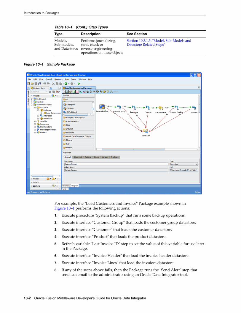
Introduction to Packages
10-2 Oracle Fusion Middleware Developer's Guide for Oracle Data Integrator
Figure 10–1 Sample Package
For example, the "Load Customers and Invoice" Package example shown in Figure 10–1 performs the following actions:
1. Execute procedure "System Backup" that runs some backup operations.
2. Execute interface "Customer Group" that loads the customer group datastore.
3. Execute interface "Customer" that loads the customer datastore.
4. Execute interface "Product" that loads the product datastore.
5. Refresh variable "Last Invoice ID" step to set the value of this variable for use later in the Package.
6. Execute interface "Invoice Header" that load the invoice header datastore.
7. Execute interface "Invoice Lines" that load the invoices datastore.
8. If any of the steps above fails, then the Package runs the "Send Alert" step that sends an email to the administrator using an Oracle Data Integrator tool.
Models, Sub-models, and Datastores
Performs journalizing, static check or reverse-engineering operations on these objects
Section 10.3.1.5, "Model, Sub-Models and Datastore Related Steps"
Table 10–1 (Cont.) Step Types
Type Description See Section
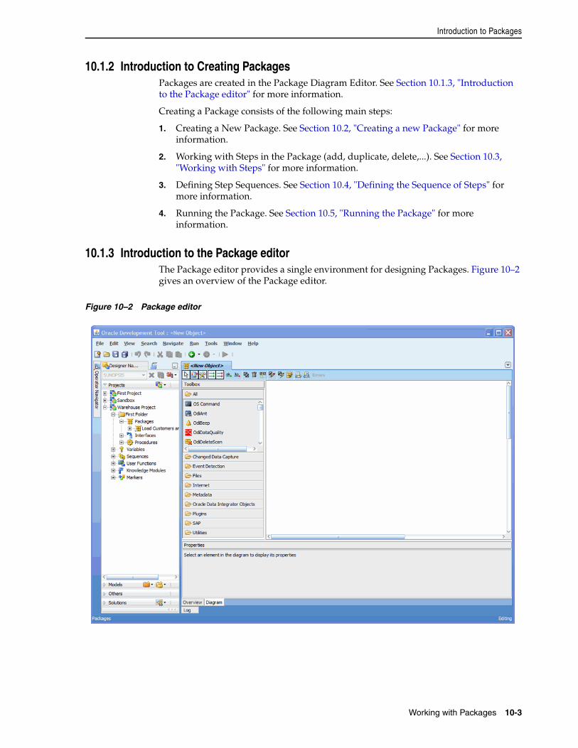
Introduction to Packages
Working with Packages 10-3
10.1.2 Introduction to Creating PackagesPackages are created in the Package Diagram Editor. See Section 10.1.3, "Introduction to the Package editor" for more information.
Creating a Package consists of the following main steps:
1. Creating a New Package. See Section 10.2, "Creating a new Package" for more information.
2. Working with Steps in the Package (add, duplicate, delete,...). See Section 10.3, "Working with Steps" for more information.
3. Defining Step Sequences. See Section 10.4, "Defining the Sequence of Steps" for more information.
4. Running the Package. See Section 10.5, "Running the Package" for more information.
10.1.3 Introduction to the Package editorThe Package editor provides a single environment for designing Packages. Figure 10–2 gives an overview of the Package editor.
Figure 10–2 Package editor
Creating a new Package
10-4 Oracle Fusion Middleware Developer's Guide for Oracle Data Integrator
10.2 Creating a new PackageTo create a new Package:
1. In the Project tree in Designer Navigator, click the Packages node in the folder where you want to create the Package.
2. Right-click and select New Package.
3. Type in the Name of the Package.
4. Go to the Diagram tab.
5. Add steps as described in Section 10.3, "Working with Steps"
6. From the File menu, click Save.
10.3 Working with StepsPackages are an organized sequence of steps. Designing a Package consists mainly in working with the steps of this Package.
10.3.1 Adding a StepAdding a step depends on the nature of the steps being inserted. See Table 10–1 for more information on the different types of steps. The procedures for adding the different type of steps are given below.
10.3.1.1 Executing an InterfaceTo insert a Flow (Interface) step:
1. Open the Package editor and go to the Diagram tab.
2. Select the interface to add to the Package from the Designer Navigator Projects tree.
3. Drag and drop the interface into the diagram. A flow Step appears.
Table 10–2 Package editor Sections
Section Location in Figure Description
Designer Navigator
Left side The Designer Navigator displays the tree views for projects, models, solutions, and other (global) components.
Package Diagram
Middle You drag components such as interfaces, procedures, datastores, models, sub-models or variables from the Designer Navigator into the Package Diagram for creating steps for these components.
You can also define sequence of steps and organize steps in this diagram.
Package Toolbox
Left side of the Package diagram
The Toolbox shows the list of Oracle Data Integrator tools available and that can be added to a Package. These tools are grouped by type.
Package Toolbar
Top of the Package diagram The Package Toolbar provides tools for organizing and sequencing the steps in the Package.
Properties Panel
Under the Package diagram This panel displays the properties for the object that is selected in the Package Diagram.
Working with Steps
Working with Packages 10-5
4. Click the step icon in the diagram. The properties panel opens.
5. In the General tab, edit the Step Name field.
6. From the File menu, click Save.
10.3.1.2 Executing a ProcedureTo insert a Procedure step:
1. Open the Package editor and go to the Diagram tab.
2. Select the procedure to add to the Package from the Designer Navigator Projects tree.
3. Drag and drop the procedure into the diagram. A procedure step appears.
4. Click the step icon in the diagram. The properties panel opens.
5. In the General tab, edit the Step Name field.
6. In the Options tab, set the procedure options if needed.
7. From the File menu, click Save.
10.3.1.3 Variable StepsThere are different variable steps within Oracle Data Integrator:
■ Declare Variable: When a variable is used in a Package (or in elements of the topology which are used in the Package), it is strongly recommended that you insert a Declare Variable step in the Package. This step explicitly declares the variable in the Package.
■ Refresh Variable: This step refreshes the variable by running the query specified in the variable definition.
■ Set Variable: There are two functions for this step:
■ Assign sets the current value of a variable.
■ Increment increases or decreases a numeric value by the specified amount.
■ Evaluate Variable: This step compares the value of the variable with a given value according to an operator. If the condition is met, then the evaluation step is true, otherwise it is false. This step allows for branching in Packages.
Declaring a VariableTo insert a Declare Variable step:
1. Open the Package editor and go to the Diagram tab.
2. In Designer Navigator, select the variable to add to the Package from the Projects tree for a project variable or from the Others tree for a global variable.
3. Drag and drop the variable into the diagram. A variable step appears.
4. Click on the step icon in the diagram. The properties panel opens.
5. In the General tab, fill in the Step Name field. Select Declare Variable in the Step Type.
6. From the File menu, click Save.
Refreshing a VariableTo insert a Refresh Variable step:
Working with Steps
10-6 Oracle Fusion Middleware Developer's Guide for Oracle Data Integrator
1. Open the Package editor and go to the Diagram tab.
2. In Designer Navigator, select the variable to add to the Package from the Projects tree for a project variable or from the Others tree for a global variable.
3. Drag and drop the variable into the diagram. A variable step appears.
4. Click on the step icon in the diagram. The properties panel opens.
5. In the General tab, fill in the Step Name field. Select Refresh Variable in the Step Type.
6. From the File menu, click Save.
Setting a VariableTo insert a Set Variable step:
1. Open the Package editor and go to the Diagram tab.
2. In Designer Navigator, select the variable to add to the Package from the Projects tree for a project variable or from the Others tree for a global variable.
3. Drag and drop the variable into the diagram. A variable step appears.
4. Click on the step icon in the diagram. The properties panel opens.
5. In the General tab, fill in the Step Name field. Select Set Variable in the Step Type.
6. Select Assign or Increment depending on the operation you want to perform on the variable value.
7. Type in the Value field the value to set or the increment. This value may be another variable.
8. From the File menu, click Save.
Evaluating a VariableTo insert an Evaluate Variable step:
1. Open the Package editor and go to the Diagram tab.
2. In Designer Navigator, select the variable to add to the Package from the Projects tree for a project variable or from the Others tree for a global variable.
3. Drag and drop the variable into the diagram. A variable step appears.
4. Click on the step icon in the diagram. The properties panel opens.
5. In the General tab, fill in the Step Name field. Select Evaluate Variable in the Step Type.
6. Select the Operator used to compare the variable value.
7. Type in the Value field the value to compare with your variable. This value may be another variable.
8. From the File menu, click Save.
Note: You can specify a list of values in the Value field. When using the IN operator, use the semicolon character (;) to separate the values of a list.
Working with Steps
Working with Packages 10-7
An evaluate variable step can be branched based on the evaluation result. See Section 10.4, "Defining the Sequence of Steps" for more information on branching steps.
10.3.1.4 Adding Oracle Data Integrator Tool StepsOracle Data Integrator provides tools that can be used within Packages for performing simple operations. The tools are either built-in tools or Open Tools that enable the user to enrich the data integrator toolbox.
To insert an Oracle Data Integrator Tool step:
1. Open the Package editor and go to the Diagram tab.
2. From the Package Toolbox, select the tool that you want to use. Note that Open tools appear in the Plugins group.
3. Click in the Package diagram. A step corresponding to your tool appears.
4. In the General tab of the properties panel, fill in the Step Name field.
5. Set the values for the parameters of the tool. The parameters descriptions appear when you select one, and are detailed in Appendix A, "Oracle Data Integrator Tools Reference".
6. You can edit the code of this tool call in the Command tab.
7. From the File menu, click Save.
The following tools are frequently used in Oracle Data Integrator Package:
■ OdiStartScen: starts an Oracle Data Integrator scenario synchronously or asynchronously. To create an OdiStartScen step, you can directly drag and drop the scenario from the Designer Navigator into the diagram.
■ OdiInvokeWebService: invokes a web service and saves the response in an XML file.
■ OS Command: calls an Operating System command. Using an operating system command may make your Package platform-dependant.
The Oracle Data Integrator tools are listed in Appendix A, "Oracle Data Integrator Tools Reference".
10.3.1.5 Model, Sub-Models and Datastore Related StepsYou can perform journalizing, static check or reverse-engineering operations on models, sub-models, and datastores. The process for creating these steps are described in the following sections.
10.3.1.6 Checking a Model, Sub-Model or Datastore To insert a check step in a Package:
Note: When setting the parameters of a tool via the steps properties panel, graphical helpers allow value selection in a user-friendly manner. For example, if a parameter requires a project identifier, the graphical interface will redesign it and display a list of project names for selection. By switching to the Command tab, you can review the raw command and see the identifier.
Working with Steps
10-8 Oracle Fusion Middleware Developer's Guide for Oracle Data Integrator
1. Open the Package editor and go to the Diagram tab.
2. In Designer Navigator, select the model, sub-model or datastore to check from the Models tree.
3. Drag and drop this model, sub-model or datastore into the diagram.
4. In the General tab or the properties panel, fill in the Step Name field. Select Model, Datastore or Sub-Model Check in the step type.
5. Select Delete Error from the Checked Tables if you want this static check to remove erroneous rows from the tables checked in this process.
6. From the File menu, click Save.
10.3.1.7 Journalizing a Model or a DatastoreTo insert a journalizing step:
1. Open the Package editor and go to the Diagram tab.
2. In Designer Navigator, select the model or datastore to check from the Models tree.
3. Drag and drop this model or datastore into the diagram.
4. In the General tab or the properties panel, fill in the Step Name field. Select Journalizing Model or Journalizing Datastore in the step type.
5. Set the journalizing options. See Chapter 7, "Working with Changed Data Capture" for more information on these options.
6. From the File menu, click Save.
10.3.1.8 Reverse-Engineering a Model To insert a reverse-engineering step:
1. Open the Package editor and go to the Diagram tab.
2. In Designer Navigator, select the model to reverse-engineer from the Models tree.
3. Drag and drop this model into the diagram.
4. In the General tab or the properties panel, fill in the Step Name field. Select Model Reverse in the step type.
5. From the File menu, click Save.
Note: It is necessary to define the CKM in the model to perform this static check.
Note: It is necessary to define the JKM in the model to perform the journalizing operations.
Note: The reverse-engineering options set in the model definition are used for performing this reverse-engineering process.
Working with Steps
Working with Packages 10-9
10.3.2 Deleting a StepTo delete a step:
1. In the Package toolbar tab, select the Free Choice tool.
2. Select the step to delete in the diagram.
3. Right-click and then select Delete Step.
4. Click OK.
The step disappears from the diagram.
10.3.3 Duplicating a StepTo duplicate a step:
1. In the Package toolbar tab, select the Free Choice tool.
2. Select the step to duplicate in the diagram.
3. Right-click and then select Duplicate Step.
A copy of the step appears in the diagram.
10.3.4 Running a StepTo run a step:
1. In the Package toolbar tab, select the Free Choice tool.
2. Select the step to run in the diagram.
3. Right-click and then select Execute Step.
4. In the Execution window, select the execution parameters:
■ Select the Context into which the step must be executed.
■ Select the Logical Agent that will run the step.
5. Click OK.
6. The Session Started Window appears.
7. Click OK.
You can review the step execution in the Operator Navigator.
10.3.5 Editing a Step’s Linked ObjectThe step's linked object is the interface, procedure, variable, and so forth from which the step is created. You can edit this object from the Package diagram.
To edit a step's linked object:
1. In the Package toolbar tab, select the Free Choice tool.
2. Select the step to edit in the diagram.
3. Right-click and then select Edit Linked Object.
The Editor for the linked object opens.
Note: It is not possible to undo a delete operation in the Package diagram.
Defining the Sequence of Steps
10-10 Oracle Fusion Middleware Developer's Guide for Oracle Data Integrator
10.3.6 Arranging the Steps LayoutThe steps can be rearranged in the diagram in order to make it more readable.
To arrange the steps in the diagram:
1. From the Package toolbar menu, select the Free Choice tool.
2. Select the more steps you wish to arrange:
■ Keep the CTRL key pressed and select each step
■ Drag the cursor on the diagram with the left mouse button pressed.
3. To arrange the selected steps, you may either:
■ Drag them to arrange their position into the diagram
■ Right-click, then select a Vertical Alignment or Horizontal Alignment option from the context menu.
It is also possible to use the Reorganize button from the toolbar to automatically reorganize the steps.
10.4 Defining the Sequence of StepsOnce the steps are created, you must reorder them into a data processing chain. This chain has the following rules:
■ It starts with a unique step defined as the First Step.
■ Each step has two termination states: Success or Failure.
■ A step in failure or success can be followed by another step, or by the end of the Package.
■ In case of failure, it is possible to define a number of retries.
A Package has one entry point, the First Step, but several possible termination steps.
Failure ConditionsThe table below details the conditions that lead a step to a Failure state. In other situations, the steps ends in a Success state.
Step Type Failure conditions
Flow ■ Error in an interface command.
■ Maximum number or percentage of errors allowed reached.
Procedure Error in a procedure command.
Refresh Variable Error while running the refresh query.
Set Variable Error when setting the variable (invalid value).
Evaluate Variable The condition defined in the step is not matched.
Declare Variable This step has no failure condition and always succeeds.
Oracle Data Integrator Tool
Oracle Data Integrator Tool return code is different from zero. If this tool is an OS Command, a failure case is a command return code different from zero.
Journalize Datastore, Model or Sub-Model
Error in a journalizing command.
Check Datastore, Model or Sub-Model
Error in the check process.
Running the Package
Working with Packages 10-11
Defining the SequenceTo define the first step of the Package:
1. In the Package toolbar tab, select the Free Choice tool.
2. Select the step to set as the first one in the diagram.
3. Right-click and then select First Step.
The first step symbol appears on the step's icon.
To define the next step upon success:
1. In the Package toolbar tab, select the Next Step on Success tool.
2. Select one step in the diagram.
3. Keep the mouse button pressed and move the cursor to the icon of the step that must follow in case of a success, then release the mouse button.
4. Repeat this operation to link all your steps in a success path sequence. This sequence should start from the step defined as the First Step.
Green arrows representing the success path between the steps, with a ok labels on these arrows. In the case of an evaluate variable step, the label is true.
To define the next step upon failure:
1. In the Package toolbar tab, select the Next Step on Failure tool.
2. Select one step in the diagram.
3. Keep the mouse button pressed and move the cursor to the icon of the step that must follow in case of a failure, then release the mouse button.
4. Repeat this operation to link steps according to your workflow logic.
Red arrows representing the failure path between the steps, with a ko labels on these arrows. In the case of an evaluate variable step, the arrow is green and the label is false.
To define the end of the Package upon failure:
By default, a step that is linked to no other step after a success or failure condition will terminate the Package when this success or failure condition is met. You can set this behavior by editing the step’s behavior.
1. In the Package toolbar tab, select the Free Choice tool.
2. Select the step to edit.
3. In the properties panel, select the Advanced tab.
4. Select End in Processing after failure or Processing after success. The links after the step disappear from the diagram.
5. You can optionally set a Number of attempts and an Time between attempts for the step to retry a number of times with an interval between the retries.
10.5 Running the PackageTo run a Package:
Reverse Model Error in the reverse-engineering process.
Step Type Failure conditions
Running the Package
10-12 Oracle Fusion Middleware Developer's Guide for Oracle Data Integrator
1. In the Project tree in Designer Navigator, select the Package you want to execute.
2. Right-click and select Execute.
3. In the Execution window, select the execution parameters:
■ Select the Context into which the Package will be executed.
■ Select the Logical Agent that will run the step.
4. Click OK.
5. The Session Started Window appears.
6. Click OK.
You can review the Package execution in the Operator Navigator.
11
Working with Integration Interfaces 11-1
11Working with Integration Interfaces
This chapter describes how to work with integration interfaces. An overview of the interface components and the Interface Editor is provided.
This chapter includes the following sections:
■ Section 11.1, "Introduction to Integration Interfaces"
■ Section 11.2, "Introduction to the Interface Editor"
■ Section 11.3, "Creating an Interface"
■ Section 11.4, "Using the Quick-Edit Editor"
■ Section 11.5, "Designing Integration Interfaces: E-LT- and ETL-Style Interfaces"
11.1 Introduction to Integration InterfacesAn interface consists of a set of rules that define the loading of a datastore or a temporary target structure from one or more source datastores.
Before creating an integration interface in Section 11.3, "Creating an Interface", you must first understand the key components of an integration interface and the Interface Editor. An overview of the components that you use to design an integration interface is provided in Section 11.1.1, "Components of an Integration Interface". The interface Editor is described in Section 11.2, "Introduction to the Interface Editor".
11.1.1 Components of an Integration InterfaceAn integration interface is made up of and defined by the following components:
■ Target Datastore
The target datastore is the element that will be loaded by the interface. This datastore may be permanent (defined in a model) or temporary (created by the interface).
■ Datasets
One target is loaded with data coming from several datasets. Set-based operators (Union, Intersect, etc) are used to merge the different datasets into the target datastore.
Each Dataset corresponds to one diagram of source datastores and the mappings used to load the target datastore from these source datastores.
■ Diagram of Source Datastores
Introduction to Integration Interfaces
11-2 Oracle Fusion Middleware Developer's Guide for Oracle Data Integrator
A diagram of sources is made of source datastores - possibly filtered - related using joins. The source diagram also includes lookups to fetch additional information for loading the target.
Two types of objects can be used as a source of an interface: datastores from the models and interfaces. If an interface is used, its target datastore -temporary or not- will be taken as a source.
The source datastores of an interface can be filtered during the loading process, and must be put in relation through joins. Joins and filters are either copied from the models or can be defined for the interface. Join and filters are implemented in the form of SQL expressions.
■ Mapping
A mapping defines the transformations performed on one or several source columns to load one target column. These transformations are implemented in the form of SQL expressions. Each target column has one mapping per dataset. If a mapping is executed on the target, the same mapping applies for all datasets.
■ Staging Area
The staging area is a logical schema into which some of the transformations (joins, filters and mappings) take place. It is by default the same schema as the target’s logical schema.
It is possible to locate the staging area on a different location (including one of the sources). It is the case if the target’s logical schema is not suitable for this role. For example, if the target is a file datastore, as the file technology has no transformation capability.
Mappings can be executed either on the source, target or staging area. Filters and joins can be executed either on the source or staging area.
■ Flow
The flow describes how the data flows between the sources, the staging area if it is different from the target, and the target as well as where joins and filters take place. The flow also includes the loading and integration methods used by this interface. These are selected by choosing Loading and Integration Knowledge Modules (LKM, IKM).
■ Control
An interface implements two points of control. Flow control checks the flow of data before it is integrated into the target, Post-Integration control performs a static check on the target table at the end of the interface. The check strategy for Flow and Post-Integration Control is defined by a Check Knowledge Module (CKM).
The interfaces use the following components that should be created before the interface:
■ Datastores that will be used as sources and target of the loading process must be populated into the data models. See Chapter 5, "Creating and Reverse-Engineering a Model" for more information.
■ The correct physical and logical schemas along with their mapping in the interface’s execution context must be defined prior to creating the interface, if the staging area is to be defined in a schema different than any of the sources or the target. See Chapter 4, "Setting-up the Topology"for more information.
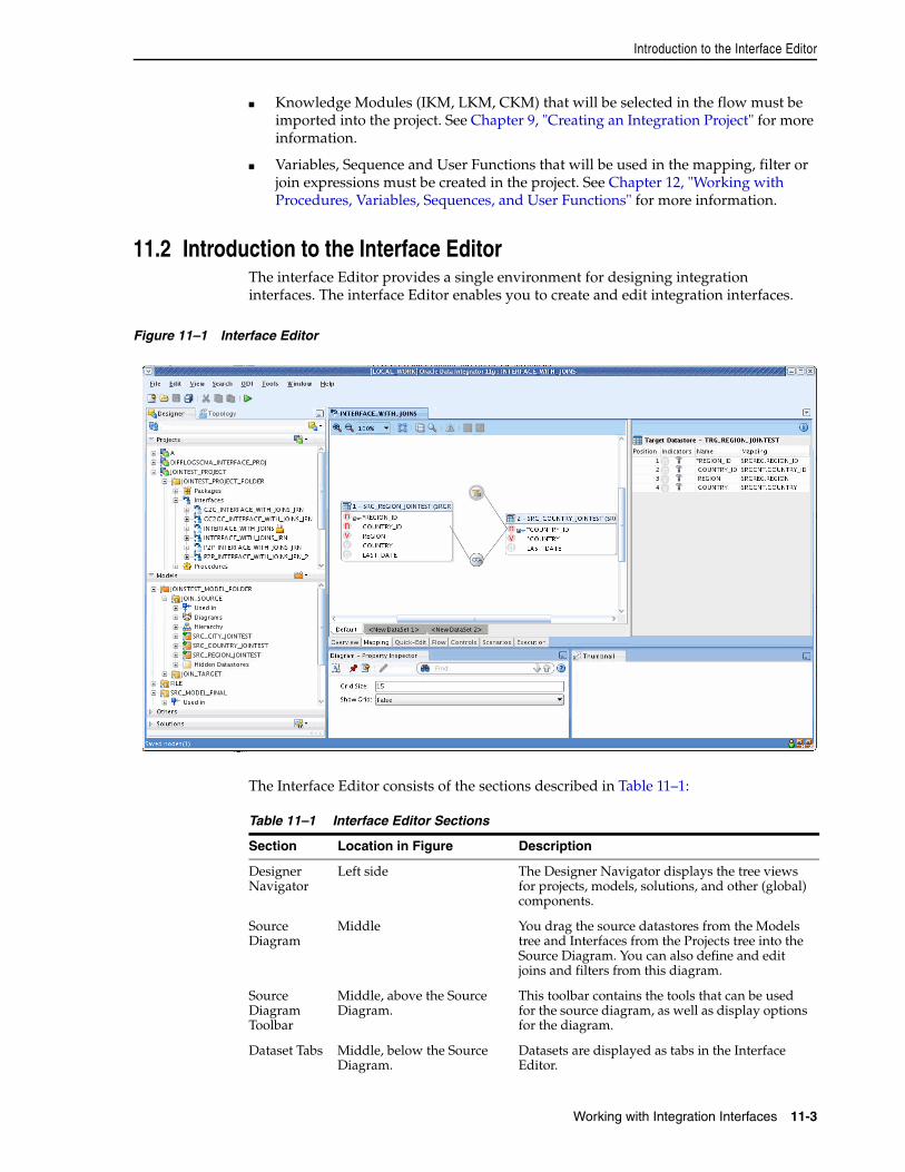
Introduction to the Interface Editor
Working with Integration Interfaces 11-3
■ Knowledge Modules (IKM, LKM, CKM) that will be selected in the flow must be imported into the project. See Chapter 9, "Creating an Integration Project" for more information.
■ Variables, Sequence and User Functions that will be used in the mapping, filter or join expressions must be created in the project. See Chapter 12, "Working with Procedures, Variables, Sequences, and User Functions" for more information.
11.2 Introduction to the Interface EditorThe interface Editor provides a single environment for designing integration interfaces. The interface Editor enables you to create and edit integration interfaces.
Figure 11–1 Interface Editor
The Interface Editor consists of the sections described in Table 11–1:
Table 11–1 Interface Editor Sections
Section Location in Figure Description
Designer Navigator
Left side The Designer Navigator displays the tree views for projects, models, solutions, and other (global) components.
Source Diagram
Middle You drag the source datastores from the Models tree and Interfaces from the Projects tree into the Source Diagram. You can also define and edit joins and filters from this diagram.
Source Diagram Toolbar
Middle, above the Source Diagram.
This toolbar contains the tools that can be used for the source diagram, as well as display options for the diagram.
Dataset Tabs Middle, below the Source Diagram.
Datasets are displayed as tabs in the Interface Editor.
Creating an Interface
11-4 Oracle Fusion Middleware Developer's Guide for Oracle Data Integrator
11.3 Creating an InterfaceCreating an interface follows a standard process which can vary depending on the use case. The following step sequence is usually performed when creating an interface, and can be used as a guideline to design your first interfaces:
1. Create a New Interface
2. Define the Target Datastore
3. Define the Datasets
4. Define the Source Datastores and Lookups
5. Define the Mappings
6. Define the Interface Flow
7. Set up Flow Control and Post-Integration Control
8. Execute the Integration Interface
Note that you can also use the Quick-Edit Editor to perform the steps 2 to 5. See Section 11.4, "Using the Quick-Edit Editor" for more information.
11.3.1 Create a New InterfaceTo create a new interface:
1. In Designer Navigator select the Interfaces node in the folder under the project where you want to create the interface.
2. Right-click and select New Interface. The Interface Editor is displayed.
3. On the Definition tab fill in the interface Name.
Interface Editor tabs
Middle, below the Dataset tabs
The Interface Editor tabs are ordered according to the interface creation process. These tabs are:
■ Overview
■ Mapping
■ Quick-Edit
■ Flow
■ Controls
■ Scenarios
■ Execution
Target Datastore Panel
Upper right You drag the target datastore from the Models tree in the Designer Navigator into the Target Datastore panel. The target datastore, with the mapping for each column, is displayed in this panel. To edit the datastore in the Property Inspector, select the datastore’s title or a specific column. You can also create a temporary target for this interface from this panel.
Property Inspector
Bottom Displays properties for the selected object.
If the Property Inspector does not display, select Property Inspector from the View menu.
Table 11–1 (Cont.) Interface Editor Sections
Section Location in Figure Description
Creating an Interface
Working with Integration Interfaces 11-5
4. Select a Staging Area and an Optimization Context for your interface.
5. Go to the Mapping tab to proceed. The steps described in Section 11.3.2, "Define the Target Datastore" to Section 11.3.5, "Define the Mappings" take place in the Mapping tab of the Interface Editor.
11.3.2 Define the Target DatastoreThe target datastore is the element that will be loaded by the interface. This datastore may be permanent (defined in a model) or temporary (created by the interface in the staging area).
11.3.2.1 Permanent Target DatastoreTo insert the permanent target datastore in an interface:
1. In the Designer Navigator, expand the Models tree and expand the model or sub-model containing the datastore to be inserted as the target.
2. Select this datastore, then drag it into the Target Datastore panel. The target datastore appears.
3. In the Property Inspector, select the Context for this datastore if you want to target this datastore in a fixed context. By default, the datastore is targeted on the context into which the interface is executed. This is an optional step.
4. If you want to target a specific partition of this target datastore, select in the Property Inspector the partition or sub-partition defined for this datastore from the list. This is an optional step.
Note: The staging area defaults to the target. It may be necessary to put it on a different logical schema if the target does not have the required transformation capabilities for the interface. This is the case for File, JMS, etc. logical schemas. After defining the target datastore for your interface, you will be able to set a specific location for the Staging Area from the Overview tab by clicking the Staging Area Different From Target option and selecting a logical schema that will be used as the staging area.
If your interface has a temporary target datastore, then the Staging Area Different From Target option is grayed out. In this case, the staging area as well as the target are one single schema, into which the temporary target is created. You must select here this logical schema.
Oracle Data Integrator includes a built-in lightweight database engine that can be used when no database engine is available as a staging area (for example, when performing file to file transformations). To use this engine, select In_MemoryEngine as the staging area schema. This engine is suitable for processing small volumes of data only.
The optimization context defines the physical organization of the datastores used for designing an optimizing the interface. This physical organization is used to group datastores into sourcesets, define the possible locations of transformations and ultimately compute the structure of the flow. For example, if in the optimization context, two datastores on two different logical schema are resolved as located in the same data server, the interface will allow a join between them to be set on the source.
Creating an Interface
11-6 Oracle Fusion Middleware Developer's Guide for Oracle Data Integrator
Once you have defined your target datastore you may wish to view its data.
To display the data of the permanent target datastore of an interface:
1. Right-click the title of the target datastore in the Target Datastore panel.
2. Select Data...
The Data Editor containing the data of the target datastore appears. Data in a temporary target datastore cannot be displayed since this datastore is created by the interface.
11.3.2.2 Temporary Target DatastoreTo add a temporary target datastore:
1. In the Target Datastore panel, select the title of the target datastore <Temporary Target Datastore> to display the Property Inspector for the target datastore.
2. On the Diagram Property tab of Property Inspector, type in a Name for this datastore.
3. Select the Context for this datastore if you want to target this datastore in a predefined context. By default, the datastore is targeted on the context into which the interface is executed. This is an optional step.
4. Specify the Temporary Datastore Location. Select Work Schema or Data Schema if you wish to create the temporary datastore in the work or data schema of the physical schema that will act as the staging area. See Chapter 4, "Setting-up the Topology" for more information on schemas.
5. Go to the Overview tab and select the logical schema into which this temporary target datastore is created.
The temporary target datastore is created without columns. They must be added to define its structure.
To add a column to a temporary target datastore:
1. In the Target Datastore panel, right-click the title bar that shows the name of the target datastore.
2. Select Add Column.
3. A new empty column appears in the Target Datastore panel. Select this new column.
4. In Diagram Property tab of the Target Mapping Property Inspector give the new column definition in the Target Column field group. You must define the column Name, Datatype, Length and Scale.
To delete a column from a temporary target datastore:
1. Right-click the column to be deleted In the Target Datastore panel.
2. Select Delete.
To add one or several columns from a source datastore to a temporary target datastore:
Note: The temporary target datastore will be created only if you activate the IKM option CREATE_TARG_TABLE when defining the flow.
Creating an Interface
Working with Integration Interfaces 11-7
1. Add the source datastore as described in Section 11.3.4, "Define the Source Datastores and Lookups".
2. In the Source Diagram, select the source datastore columns you wish to add.
3. Right-click and select Add Column to Target Table.
4. The columns are added to the target datastore. Data types are set automatically.
To add all of the columns from a source datastore to a temporary target datastore:
1. Add the source datastore.
2. In the Source Diagram, select the title of the entity representing the source datastore.
3. Right-click and select Add to Target.
4. The columns are added to the Target Datastore. Data types are set automatically.
11.3.2.3 Define the Update KeyIf you want to use update or flow control features in your interface, it is necessary to define an update key on the target datastore.
The update key identifies each record to update or check before insertion into the target. This key can be a unique key defined for the target datastore in its model, or a group of columns specified as a key for the interface.
To define the update key from a unique key:
1. In the Target Datastore panel, select the title bar that shows the name of the target datastore to display the Property Inspector.
2. In the Diagram Property tab, select the Update Key from the list.
You can also define an update key from the columns if:
■ You don't have a unique key on your datastore. This is always the case on a temporary target datastore.
■ You want to specify the key regardless of already defined keys.
When you define an update key from the columns, you select manually individual columns to be part of the update key.
To define the update key from the columns:
1. Unselect the update key, if it is selected. This step applies only for permanent datastores.
2. In the Target Datastore panel, select one of the columns that is part of the update key to display the Property Inspector.
3. In the Diagram Property tab, check the Key box. A key symbol appears in front of the column in the Target Datastore panel.
4. Repeat the operation for each column that is part of the update key.
Note: Only unique keys defined in the model for this datastore appear in this list.
Creating an Interface
11-8 Oracle Fusion Middleware Developer's Guide for Oracle Data Integrator
11.3.3 Define the DatasetsA dataset represents the data flow coming from a group of datastores. Several datasets can be merged into the interface target datastore using set-based operators such as Union and Intersect. The support for datasets as well as the set-based operators supported depend on the capabilities of the staging area’s technology.
You can add, remove, and order the datasets of an interface and define the operators between them in the DataSets Configuration dialog. Note that the set-based operators are always executed on the staging area.
When designing the integration interface, the mappings for each dataset must be consistent, this means that each dataset must have the same number of target columns mapped.
To create a new dataset:
1. In the Source Diagram toolbar click Add /Remove DataSet... to display the DataSet Configuration dialog.
2. Click Add New DataSet... A new line is added for the new dataset at the bottom of the list.
3. In the DataSet Name field, give the name of the new dataset. This name will be displayed in the dataset tab.
4. In the Operator field, select the set-based operator for your dataset. Repeat steps 2 to 4 if you wish to add more datasets.
5. Click Close.
To arrange the order of the datasets:
1. Select a dataset in the DataSet Configuration dialog.
2. Click the Up and Down arrows to move the dataset up or down in the list.
To delete a dataset:
1. Select a dataset in the DataSet Configuration dialog.
2. Click Delete.
11.3.4 Define the Source Datastores and LookupsThe source datastores contain data used to load the target datastore. Two types of datastores can be used as an interface source: datastores from the models and temporary datastores that are the target of an interface.
When using a temporary datastore that is the target of another interface as a source or as a lookup table, you can choose:
■ To use a persistent temporary datastore: You will run a first interface creating and loading the temporary datastore, and then a second interface sourcing from it. In this case, you would typically sequence the two interfaces in a package.
■ Not to use a persistent datastore: The second interface generates a sub-select corresponding to the loading of the temporary datastore. This option is not always available as it requires all datastores of the source interface to belong to the same data server (for example, the source interface must not have any source sets). You activate this option by selecting Use Temporary Interface as Derived Table on the source. Note the following when using a temporary interface as derived table:
Creating an Interface
Working with Integration Interfaces 11-9
– The generated sub-select syntax can be either a standard sub-select syntax (default behavior) or the customized syntax from the IKM used in the first interface.
– All IKM commands except the one that defines the derived-table statement option Use current command for Derived Table sub-select statement are ignored. This limitation causes, for example, that temporary index management is not supported.
The source datastores of an interface can be filtered during the loading process and must be put in relation through joins. Joins and filters can be automatically copied from the model definitions and can also be defined for the interface.
A lookup is a datastore (from a model or the target datastore of an interface) - called the lookup table - associated to a source datastore - the driving table - via a join expression and from which data can be fetched and used into mappings.
The lookup data is used in the mapping expressions. Lookup tables are added with the Lookup Wizard. Depending on the database, two syntaxes can be used for a lookup:
■ SQL Left-Outer Join in the FROM clause: The lookup is processed as a regular source and a left-outer join expression is generated to associate it with its driving table.
■ SQL expression in the SELECT clause: The lookup is performed within the select clause that fetches the data from the lookup table. This second syntax may sometimes be more efficient for small lookup tables.
11.3.4.1 Define the Source DatastoresTo add a permanent-type source datastore to an interface:
1. In the Designer Navigator, expand the Models tree and expand the model or sub-model containing the datastore to be inserted as a source.
2. Select this datastore, then drag it into the Source Diagram. The source datastore appears in the diagram.
3. In the Diagram Property tab of the Property Inspector, modify the Alias of the source datastore. The alias is used to prefix column names. This is an optional step that improves readability of the mapping, joins and filter expressions.
4. Select the Context for this datastore if you want to source data from this datastore in a fixed context. By default, the datastore is accessed in the context into which the interface is executed. This is an optional step.
5. If you want to source from a specific partition of this datastore, select the partition or sub-partition defined for this datastore from the list. This is an optional step
Caution: If there are in the model filters defined on the datastore, or references between this datastore and datastores already in the diagram, they appear along with the datastore. These references and filters are copied as joins and filters in the interface. They are not links to the references and filters from the model. Therefore, modifying a reference or a filter in a model does not affect the join or filter in the interface, and vice versa.
Creating an Interface
11-10 Oracle Fusion Middleware Developer's Guide for Oracle Data Integrator
To add a temporary-type source datastore to an interface:
1. In the Designer Navigator, expand the Projects tree and expand the project containing the interface to be inserted as a source.
2. Select this interface, then drag it into the Source Diagram. The source datastore appears in the diagram.
3. In the Diagram Property tab of the Property Inspector, modify the Alias of the source datastore. The alias is used to prefix column names. This is an optional step that improves readability of the mapping, joins and filter expressions.
4. If you want this interface to generate a sub-select corresponding to the loading of the temporary datastore, check the Use Temporary Interface as Derived Table (Sub-Select) box. If this box is not checked, make sure to run the interface loading the temporary datastore before running the current interface.
To delete a source datastore from an interface:
1. Right-click the title of the entity representing the source datastore in the Source Diagram.
2. Select Delete.
3. Click OK in the Confirmation dialog.
The source datastore disappears, along with the associated filters and joins. Note that if this source datastore contained columns that were used in mappings, these mappings will be in error.
To display the data or the number for rows of a source datastore of an interface:
1. Right-click the title of the entity representing the source datastore in the Source Diagram.
2. Select Number of Lines to display the number of rows in this source datastore or Display Data to display the source datastore data.
A window containing the number or rows or the data of the source datastore appears.
11.3.4.2 Define LookupsTo add a lookup to an interface:
1. From the Source Diagram toolbar menu, select Add a new Lookup. The Lookup Tables Wizard opens.
2. In the Lookup Table Wizard select your Driving Table from the left pane. Source datastores for the current diagram appear here. Note that lookups do not appear in the list.
3. From the tree in the Lookup Table pane on the right, do one of the following:
■ From the Datastores tab, select a datastore from a model to use as a lookup table.
Note: If the source datastore is journalized, it is possible to use only the journalized data in the interface flow. Check the Journalized Data Only box in the source datastore properties. A Journalizing filter is automatically created in the diagram. See Chapter 7, "Working with Changed Data Capture" for more information.
Creating an Interface
Working with Integration Interfaces 11-11
■ From the Interfaces tab, select an interface whose target will be used as the lookup table. If this target is temporary and you want this interface to generate a sub-select corresponding to the loading of the temporary datastore, check the Use Temporary Interface as Derived Table (Sub-Select) box. If this box is not checked, make sure to run the interface loading the temporary datastore before running the current interface.
4. Modify the Alias of the lookup table. The alias is used to prefix column names. This is an optional step that improves readability of the expressions.
5. Click Next.
6. On the left pane, select one or several source columns from the driving table you wish to join.
7. On the right pane, select one or several columns of the lookup table you wish to join.
8. Click Join. The join condition appears in the Lookup condition text field. You can edit the join condition in this field.
9. Specify the Lookup options:
■ Execute on: Execution location (Source or Staging Area) of the lookup.
■ Lookup type: Indicates whether to use SQL left-outer join in the FROM clause or SQL expression in the SELECT clause during the SQL code generation.
10. Click Finish. Your lookup appears in the Source Diagram of your dataset.
To edit Lookup tables:1. Select a Lookup in the Source Diagram of your dataset. The Lookup table
properties are displayed in the Property Inspector.
2. Edit the lookup properties in the Property Inspector.
You cannot change from here the driving and lookup tables. To change these, you must delete the lookup and recreate it.
To delete a Lookup table:1. Select a Lookup in the Source Diagram of your dataset.
2. Right-click and select Delete.
11.3.4.3 Define Filters on the SourcesTo define a filter on a source datastore:
1. In the Source Diagram, select one or several columns in the source datastore you want to filter, and then drag and drop these columns onto the source diagram. A filter appears. Click this filter to open the Property Inspector.
2. In the Diagram Property tab of the Property Inspector, modify the Implementation expression to create the required filter. You may call the expression Editor by clicking Launch Expression Editor button. The filter expression must be in the form SQL condition. For example, if you want to take in the CUSTOMER table (that is the source datastore with the CUSTOMER alias)
Note: In order to use columns from this lookup, you need to expand the graphical artifact representing it. Right-click the lookup icon in the diagram and select View As > Symbolic.
Creating an Interface
11-12 Oracle Fusion Middleware Developer's Guide for Oracle Data Integrator
only those of the customers with a NAME that is not null, an expression would be CUSTOMER.NAME IS NOT NULL.
3. Select the execution location: Source or Staging Area.
4. Click the Check the Expression in the DBMS to validate the expression.
5. Check the Active Filter box to enable or disable this filter. It is enabled by default.
6. If you want ODI to automatically generate a temporary index to optimize the execution of the filter, select the index type to create from the Create Temporary Index list. This step is optional.
To delete a filter on a source datastore:
1. In the Source Diagram, select the filter.
2. Right-click and select Delete.
To display the data or the number of rows resulting from a filter:
1. In the Source Diagram, select the filter.
2. Right-click and select Number of Lines to display the number of rows after the filter or Display Data to display the filtered data.
A window containing the data or the number of rows after the filter appears.
11.3.4.4 Define Joins between SourcesTo create a join between the source datastores of an interface:
1. In the Source Diagram, select a column in the first source datastore to join, and drag and drop this column on a column in the second source datastore to join. A join linking the two datastores appears. Click this join to open the Property Inspector.
2. In the Diagram Property tab of the Property Inspector, modify the Implementation expression to create the required join. You may call the expression Editor by clicking Launch Expression Editor button. The join expression must be in the form of an SQL expression.
3. Select the execution location: Source or Staging Area.
4. Optionally, you can click the Check the Expression in the DBMS to validate the expression.
5. Select the type of join (right/left, inner/outer, cross, natural). The text describing which rows are retrieved by the join is updated.
6. If you want to use an ordered join syntax for this join, check the Ordered Join (ISO) box and then specify the Order Number into which this join is generated. This step is optional.
7. Check the Active Clause box to enable or disable this join. You can disable a join for debugging purposes. It is enabled by default.
Note: The creation of temporary indexes may be a time consuming operation in the overall flow. It is advised to review the execution statistics and to compare the execution time saved with the indexes to the time spent creating them.
Creating an Interface
Working with Integration Interfaces 11-13
8. If you want ODI to automatically generate temporary indexes to optimize the execution of this join, select the index type to create from the Temporary Index On lists. This step is optional.
To delete a join between source datastores of an interface:
1. In the Source Diagram, select the join.
2. Right-click and select Delete.
To display the data or the number of rows resulting from a join:
1. In the Source Diagram, select the join.
2. Right-click and select Number of Lines to display the number of rows returned by the join or Display Data to display the result of the join.
A window containing the data or the number of rows resulting from the join appears.
11.3.5 Define the MappingsA mapping defines the transformations on one or several source columns to load one target column.
Empty mappings are automatically filled when you add a source or target datastore by column name matching. The user-defined mapping always takes precedence over automatic mapping.
To regenerate the automatic mapping by column name matching:
1. Right-click the target datastore.
2. Select Redo Auto Mapping.
The target datastore columns are automatically mapped on the source datastores' columns with the same name.
To define the mapping of a target column:
1. In the Target Datastore Panel, select the column of the target datastore to display the Property Inspector.
2. In the Diagram Property tab of the Property Inspector, modify the Implementation to create the required transformation. The columns of all the tables in the model can be drag-and-dropped into the text. You may call the expression Editor by clicking Launch Expression Editor.
3. Optionally, click Check the expression in the DBMS to validate the expression.
4. Select the execution location: Source, Target or Staging Area. Some limitations exist when designing mappings. When a mapping does not respect these limitations, a red cross icon appears on the target column in the Target Datastore Panel. For example:
■ Mappings that contain constants cannot be mapped on the source without having selected a source datastore.
Note: The creation of temporary indexes may be a time consuming operation in the overall flow. It is advised to review the execution statistics and to compare the execution time saved with the indexes to the time spent creating them.
Creating an Interface
11-14 Oracle Fusion Middleware Developer's Guide for Oracle Data Integrator
■ Mappings that contain reference source columns cannot be mapped on the target.
■ A mandatory column should be mapped.
■ A mapping mapped in one dataset must be mapped in all other datasets.
5. Check the Update boxes if you want the mapping to be executed in Insert or Update operations. You can also check the UD1 to UD10 boxes to enable KM-specific options on columns. These options are optional, and must be used if the Knowledge Module documentation indicates it. Otherwise, they are ignored.
6. Check Active Mapping if you want this mapping to be used for the execution of the interface. Note that if you enter a mapping text in a disabled mapping, this mapping will automatically be enabled.
11.3.6 Define the Interface FlowIn the Flow tab, you define the loading and integration strategies for mapped data. Oracle Data Integrator automatically computes the flow depending on the configuration in the interface's diagram. It proposes default KMs for the data flow. The Flow tab enables you to view the data flow and select the KMs used to load and integrate data.
In the flow, the following items appear:
■ Source Sets: Source Datastores that are within the same dataset, located on the same physical data server and which are joined with Joins located on the Source are grouped in a single source set in the flow diagram. A source set represents a group of datastores that can be extracted at the same time.
■ DataSets: Datasets appear as yellow boxes in the Staging Area.
■ Staging Area: It appears as a box that includes the different datasets, the target (if located on the same data server), and possibly some of the sources (if located on the same data server).
■ Target: It appears as a separate box if it is located in a different schema from the staging area (If the Staging Area Different from Target option is selected).
You use the following KMs in the flow:
■ LKM: They define how data is moved. One LKM is selected for each Source Set for moving data from the sources to the staging area. It can be also selected to move data from the Staging Area - when different from the Target - to the Target, when a single technology IKM is selected for the Staging Area.
■ IKM: They define how data is integrated into the target. One IKM is typically selected on the Target. When the staging area is different from the target, the selected IKM can be a multi-technology IKM that moves and integrates data from the Staging Area into the Target.
Tip: Before proceeding, you can check the consistency and errors in your diagram by clicking the Display Interface Errors Report in the Source Diagram Toolbar. This report will show you errors that may exist in your interface such as mappings incorrectly located.
At this stage, you may receive some errors because the Knowledge Modules are not selected yet for this interface.
Creating an Interface
Working with Integration Interfaces 11-15
To change the LKM in use:1. In the Flow tab, select one of the Source Sets or the Staging Area, if it is not into
the Target group, by clicking its title. The Property Inspector opens for this object.
2. If you are working on a Source Set, change the Name of this source set. This step is optional and improves readability of the flow.
3. Select a LKM from the LKM Selector list.
4. KMs are set with default options that work in most use cases. You can optionally modify the KM Options.
Note that KM options of the previous KM are retained using homonymy when switching from a KM to another. By changing KMs several times you might lose custom KM option values.
To change the IKM in use:1. In the Flow tab, select the Target by clicking its title. The Property Inspector opens
for this object.
2. In the Property Inspector, select a IKM from the IKM Selector list.
3. Check the Distinct option if you want to automatically apply a DISTINCT statement on your data flow and avoid possible duplicate rows.
4. KMs are set with default options that work in most use cases. You can optionally modify the KM Options.
Note that KM options of the previous KM are retained using homonymy when switching from a KM to another. By changing KMs several times you might lose custom KM option values.
An important option to set is FLOW_CONTROL. This option triggers flow control and requires that you set up flow control.
11.3.7 Set up Flow Control and Post-Integration ControlIn an integration interface, it is possible to set two points of control. Flow Control checks the data in the incoming flow before it gets integrated into the target, and Post-Integration Control checks the target datastore as if in a static check at the end of the interface.
Note: Only KMs that have already been imported in the project can be selected in the interface. Make sure that you have imported the appropriate KMs in the project before proceeding.
Note: Knowledge modules with an Incremental Update strategy, as well as flow control, require that you set an update key for the target datastore of the interface.
Note: For more information on the KMs and their options, refer to the KM description and to the Oracle Fusion Middleware Connectivity and Knowledge Modules Guide for Oracle Data Integrator.
Creating an Interface
11-16 Oracle Fusion Middleware Developer's Guide for Oracle Data Integrator
11.3.7.1 Set up Flow ControlThe flow control strategy defines how data is checked against the constraints defined on the target datastore before being integrated into this datastore. It is defined by a CKM. In order to have the flow control running, you must set the FLOW_CONTROL option in the IKM to true. Flow control also requires that an update key is selected on the target datastore of this interface. Refer to Section 11.3.2.3, "Define the Update Key" for more information.
To define the CKM used in an interface:
1. In the Controls tab of the interface, select a CKM from the CKM Selector list.
2. Set the KM Options.
3. Select the Constraints to be checked.
4. Fill in the Maximum number of errors allowed. Note that if you leave this field empty, an infinite numbers of errors is allowed. The interface stops during the flow control (if any) or the post-integration control (if any) if the number of errors allowed is reached.
5. Check the % box if you want the interface to fail when a percentage of errors is reached during flow or post-integration control, rather than a fixed number of errors. This percentage is calculated with the following formula:
errors_detected * 100 / checked_rows where:
■ checked_rows is the number of checked rows during flow and post-integration control.
■ errors_detected are the number of errors detected during flow and post-integration control.
This formula is calculated at the end of the execution of the interface. If the result of this formula is superior to the indicated percentage, the interface status will be in error. If the interface falls into error during a flow control, no changes are performed into the target. If the interface falls into error after a post-integration control, the changes performed to the target are not committed by the Knowledge Module.
11.3.7.2 Set up Post-Integration ControlThe post-integration control strategy defines how data is checked against the constraints defined on the target datastore. This check takes place once the data is integrated into the target datastore. It is defined by a CKM. In order to have the post-integration control running, you must set the STATIC_CONTROL option in the IKM to true. Post-integration control requires that a primary key is defined in the data model for the target datastore of your interface.
Concerning the maximum number of errors allowed the same behavior is applied as for flow control.
Post-integration control uses the same CKM as the flow control.
11.3.8 Execute the Integration InterfaceOnce the interface is created, it is possible to execute it.
To run an interface:
1. While editing the interface, click Execute in the toolbar.
Using the Quick-Edit Editor
Working with Integration Interfaces 11-17
2. In the Execution window, select the execution parameters:
■ Select the Context into which the interface must be executed.
■ Select the Logical Agent that will run the interface.
3. Click OK.
4. The Session Started Window appears.
5. Click OK.
11.4 Using the Quick-Edit EditorYou can use the Quick-Edit Editor to perform the same actions as on the Mapping tab of the Interface Editor in a non-graphical form:
■ Adding and Removing a Component
■ Editing a Component
■ Adding, Removing, and Configuring Datasets
■ Changing the Target DataStore
The Quick-Edit Editor allows to:
■ Work with the Interface components in tabular form.
■ Perform mass updates of components properties when editing the components. See Section 11.4.2, "Editing a Component" for more information.
■ Use keyboard navigation for common tasks. See Section 11.4.6, "Using Keyboard Navigation for Common Tasks" for more information.
The properties of the following components are displayed in tabular form and can be edited in the Quick-Edit Editor:
■ Sources
■ Lookups
■ Joins
■ Filters
■ Mappings
Note that components already defined on the Mapping tab of the Interface Editor are displayed in the Quick-Edit Editor and that the components defined in the Quick-Edit Editor will also be reflected in the Mapping tab.
11.4.1 Adding and Removing a ComponentWith the Quick-Edit Editor, you can add or remove components of an integration interface.
11.4.1.1 Adding ComponentsTo add a source, lookup, join, filter, or temporary target column with the Quick-Edit Editor:
1. In the Interface Editor, go to the Quick-Edit tab.
2. From the Select DataSet list, select the dataset to which you want to add the new components.
Using the Quick-Edit Editor
11-18 Oracle Fusion Middleware Developer's Guide for Oracle Data Integrator
3. Expand the section of the components to add.
4. From the toolbar menu, select Add.
5. The next tasks depend on the type of component you are adding:
If you are adding a new temporary target column, a new line representing the temporary target column is added to your target datastore table. You can modify directly the cells of this temporary target column in the target datastore table according to your needs.
If you are adding a source, lookup, join, or filter, a wizard will guide you through the next steps.
■ Add Sources Wizard
■ Lookup Tables Wizard
■ Join Table Wizard
■ Filter Table Wizard
Add Sources WizardUse the Add Sources Wizard to add the sources of your Interfaces. You can add datastores or integration interfaces as sources.
To a datastore as a source of the Interface:
1. Select the Datastores tab.
The Add Sources Wizard displays the list of datastores with their Models and Model folders that can be used as a source of the Interface.
2. From the list, select the datastore that you want to add as a source of the Interface.
Note that you can browse through the list or filter this list by entering a partial or complete name of the datastore in the search field.
3. Modify the alias of the datastore (optional).
4. Click OK.
To add an integration interface as a source of the Interface:
1. Select the Interfaces tab.
The Add Sources Wizard displays the list of Interfaces.
2. From the list, select the Interface that you want to add as a source of the Interface.
Note that you can browse through the list or filter this list by entering a partial or complete name of the Interface in the search field.
3. Modify the alias of the Interface (optional).
4. Click OK.
Lookup Tables WizardUse the Lookup Tables Wizard to add lookup tables to your integration interface. For more information, see Section 11.3.4.2, "Define Lookups".
Join Table WizardUse the Join Table Wizard to create joins between the source datastores of an interface.
To create a join:
Using the Quick-Edit Editor
Working with Integration Interfaces 11-19
1. From the Left Source list in the Specify Join Criteria section, select the source datastore that contains the left column for your join.
2. From the Right Source list, select the source datastore that contains the right column for your join.
3. Select the left source and right source column and click Join. The join condition is displayed in the Join Condition field.
4. You can modify the join condition to create the required join. Note that the join expression must be in the form of an SQL expression. You may call the Expression Editor by clicking Launch Expression Editor to modify the join condition.
5. Select the execution location: Source or Staging Area.
6. Select the type of join you want to create: Inner Join, Cross, Natural, Left Outer, Right Outer, or Full. The text describing which rows are retrieved by the join is updated.
7. Click OK.
Filter Table WizardUse the Filter Table Wizard to define the filter criteria of your source datastore.
To define a filter on a source datastore:
1. From the source list, select the source datastore you want to filter.
2. From the columns list, select the source column on which you want to create the filter. The filter condition is displayed in the Filter Condition field.
3. You can modify this filter condition to create the required filter. You may call the expression Editor by clicking Launch Expression Editor. Note that the filter expression must be in the form SQL condition.
4. Select the execution location: Source or Staging Area.
5. Click OK.
11.4.1.2 Removing ComponentsTo remove a source, lookup, join, filter, or temporary target column with the Quick-Edit Editor:
1. In the Interface Editor, go to the Quick-Edit tab.
2. From the Select DataSet list, select the dataset from which you want to remove the components.
3. Expand the section of the components to remove.
4. Select the lines you want to remove.
5. From the toolbar menu, select Remove.
The selected components are removed.
11.4.2 Editing a ComponentTo edit the sources, lookups, joins, filters, mappings or target column properties with the Quick-Edit Editor:
1. In the Interface Editor, go to the Quick-Edit tab.
Using the Quick-Edit Editor
11-20 Oracle Fusion Middleware Developer's Guide for Oracle Data Integrator
2. From the Select DataSet list, select the dataset that contains the components to modify.
3. Expand the section of the component to modify.
4. Modify the table entry either by selecting or entering a new value.
Performing Mass UpdatesThe mass updates allow quick updates of several component properties at a time. You can perform mass updates in the Quick-Edit Editor using the Copy-Paste feature in the component tables.
To perform a mass update of component properties:
1. In the component table, select the cell that contains the value you want to apply to other cells.
2. Copy the cell value.
3. Select multiple cells in the same column.
4. Paste the copied value.
The copied value is set to all selected cells.
11.4.3 Adding, Removing, and Configuring DatasetsYou can create, remove, and configure datasets with the Quick-Edit Editor.
To create, remove, and configure datasets with the Quick-edit Editor:
1. From the Select DataSet list, select Manage DataSets...
2. The DataSets Configuration dialog is displayed. Define the datasets as described in Section 11.3.3, "Define the Datasets".
11.4.4 Changing the Target DataStoreYou can change the target datastore of your integration interface with the Quick-Edit Editor.
To change the target datastore of your Interface with the Quick-Edit Editor:
1. In the Interface Editor, go to the Quick-Edit tab.
2. Expand the Mappings section.
3. Click Add or Modify Target Datastore.
4. In the Add or Modify Target Datastore Dialog, do one of the following:
■ If you want to create a temporary target datastore, select Use Temporary Target and enter the name of the new temporary target datastore.
■ If you want to use a permanent target datastore, select the datastore that you want to add as the target of the Interface from the list.
Note that you can browse through the list or filter this list by entering a partial or complete name of the datastore in the search field.
Note: The Copy-Paste feature is provided for text cells, drop down lists, and checkboxes.
Designing Integration Interfaces: E-LT- and ETL-Style Interfaces
Working with Integration Interfaces 11-21
5. Click OK.
11.4.5 Customizing TablesThere two ways to customize the tables of the Quick-Edit Editor:
■ From the table toolbar, select Select Columns and then, from the drop down menu, select the columns to display in the table.
■ Use the Customize Table Dialog.
1. From the table toolbar, select Select Columns.
2. From the drop down menu, select Select Columns...
3. In the Customize Table Dialog, select the columns to display in the table.
4. Click OK.
11.4.6 Using Keyboard Navigation for Common TasksThis section describes the keyboard navigation in the Quick-Edit Editor.
Table 11–2 shows the common tasks and the keyboard navigation used in the Quick-Edit Editor.
11.5 Designing Integration Interfaces: E-LT- and ETL-Style InterfacesIn an E-LT-style integration interface, ODI processes the data in a staging area, which is located on the target. Staging area and target are located on the same RDBMS. The data is loaded from the source(s) to the target. To create an E-LT-style integration interface, follow the standard procedure described in Section 11.3, "Creating an Interface".
Table 11–2 Keyboard Navigation for Common Tasks
Navigation Task
Arrow keys Navigate: move one cell up, down, left, or right
TAB Move to next cell
SHIFT+TAB Move to previous cell
SPACEBAR Start editing a text, display items of a list, or change value of a checkbox
CTRL+C Copy the selection
CTRL+V Paste the selection
ESC Cancel an entry in the cell
ENTER Complete a cell entry and move to the next cell or activate a button
DELETE Clear the content of the selection (for text fields only)
BACKSPACE Delete the content of the selection or delete the preceding character in the active cell (for text fields only)
HOME Move to the first cell of the row
END Move to the last cell of the row
PAGE UP Move up to the first cell of the column
PAGE DOWN Move down to the last cell of the column
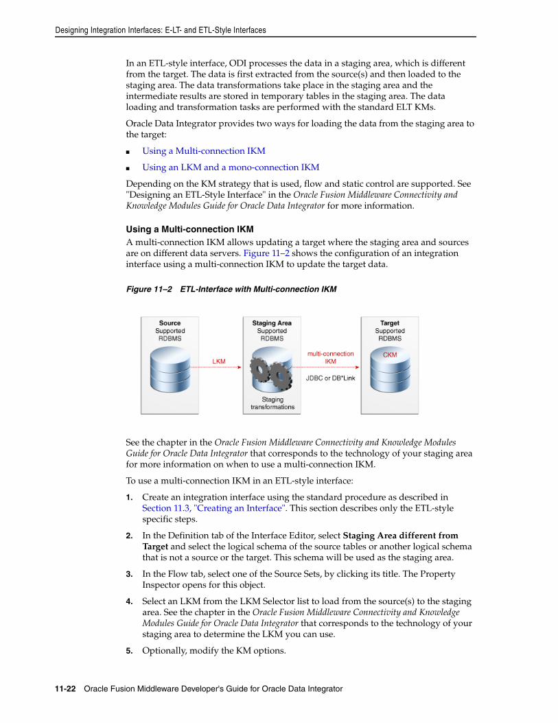
Designing Integration Interfaces: E-LT- and ETL-Style Interfaces
11-22 Oracle Fusion Middleware Developer's Guide for Oracle Data Integrator
In an ETL-style interface, ODI processes the data in a staging area, which is different from the target. The data is first extracted from the source(s) and then loaded to the staging area. The data transformations take place in the staging area and the intermediate results are stored in temporary tables in the staging area. The data loading and transformation tasks are performed with the standard ELT KMs.
Oracle Data Integrator provides two ways for loading the data from the staging area to the target:
■ Using a Multi-connection IKM
■ Using an LKM and a mono-connection IKM
Depending on the KM strategy that is used, flow and static control are supported. See "Designing an ETL-Style Interface" in the Oracle Fusion Middleware Connectivity and Knowledge Modules Guide for Oracle Data Integrator for more information.
Using a Multi-connection IKMA multi-connection IKM allows updating a target where the staging area and sources are on different data servers. Figure 11–2 shows the configuration of an integration interface using a multi-connection IKM to update the target data.
Figure 11–2 ETL-Interface with Multi-connection IKM
See the chapter in the Oracle Fusion Middleware Connectivity and Knowledge Modules Guide for Oracle Data Integrator that corresponds to the technology of your staging area for more information on when to use a multi-connection IKM.
To use a multi-connection IKM in an ETL-style interface:
1. Create an integration interface using the standard procedure as described in Section 11.3, "Creating an Interface". This section describes only the ETL-style specific steps.
2. In the Definition tab of the Interface Editor, select Staging Area different from Target and select the logical schema of the source tables or another logical schema that is not a source or the target. This schema will be used as the staging area.
3. In the Flow tab, select one of the Source Sets, by clicking its title. The Property Inspector opens for this object.
4. Select an LKM from the LKM Selector list to load from the source(s) to the staging area. See the chapter in the Oracle Fusion Middleware Connectivity and Knowledge Modules Guide for Oracle Data Integrator that corresponds to the technology of your staging area to determine the LKM you can use.
5. Optionally, modify the KM options.
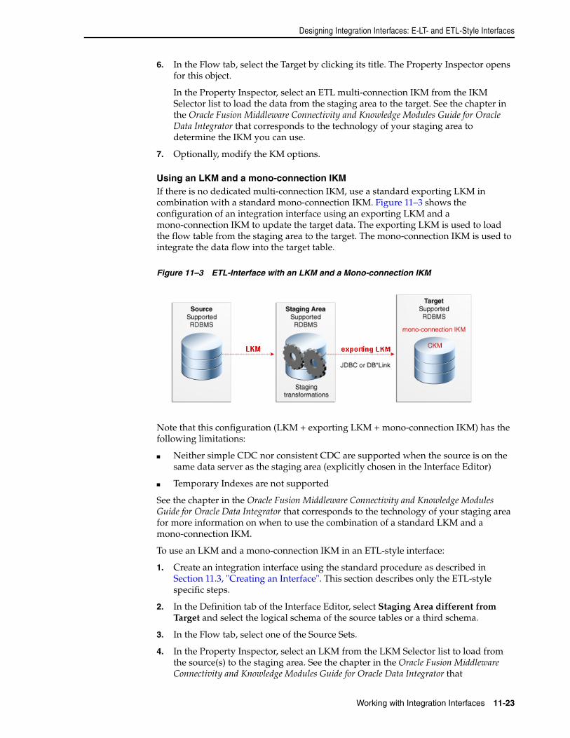
Designing Integration Interfaces: E-LT- and ETL-Style Interfaces
Working with Integration Interfaces 11-23
6. In the Flow tab, select the Target by clicking its title. The Property Inspector opens for this object.
In the Property Inspector, select an ETL multi-connection IKM from the IKM Selector list to load the data from the staging area to the target. See the chapter in the Oracle Fusion Middleware Connectivity and Knowledge Modules Guide for Oracle Data Integrator that corresponds to the technology of your staging area to determine the IKM you can use.
7. Optionally, modify the KM options.
Using an LKM and a mono-connection IKMIf there is no dedicated multi-connection IKM, use a standard exporting LKM in combination with a standard mono-connection IKM. Figure 11–3 shows the configuration of an integration interface using an exporting LKM and a mono-connection IKM to update the target data. The exporting LKM is used to load the flow table from the staging area to the target. The mono-connection IKM is used to integrate the data flow into the target table.
Figure 11–3 ETL-Interface with an LKM and a Mono-connection IKM
Note that this configuration (LKM + exporting LKM + mono-connection IKM) has the following limitations:
■ Neither simple CDC nor consistent CDC are supported when the source is on the same data server as the staging area (explicitly chosen in the Interface Editor)
■ Temporary Indexes are not supported
See the chapter in the Oracle Fusion Middleware Connectivity and Knowledge Modules Guide for Oracle Data Integrator that corresponds to the technology of your staging area for more information on when to use the combination of a standard LKM and a mono-connection IKM.
To use an LKM and a mono-connection IKM in an ETL-style interface:
1. Create an integration interface using the standard procedure as described in Section 11.3, "Creating an Interface". This section describes only the ETL-style specific steps.
2. In the Definition tab of the Interface Editor, select Staging Area different from Target and select the logical schema of the source tables or a third schema.
3. In the Flow tab, select one of the Source Sets.
4. In the Property Inspector, select an LKM from the LKM Selector list to load from the source(s) to the staging area. See the chapter in the Oracle Fusion Middleware Connectivity and Knowledge Modules Guide for Oracle Data Integrator that
Designing Integration Interfaces: E-LT- and ETL-Style Interfaces
11-24 Oracle Fusion Middleware Developer's Guide for Oracle Data Integrator
corresponds to the technology of your staging area to determine the LKM you can use.
5. Optionally, modify the KM options.
6. Select the Staging Area. In the Property Inspector, select an LKM from the LKM Selector list to load from the staging area to the target. See the chapter in the Oracle Fusion Middleware Connectivity and Knowledge Modules Guide for Oracle Data Integrator that corresponds to the technology of your staging area to determine the LKM you can use.
7. Optionally, modify the options.
8. Select the Target by clicking its title. The Property Inspector opens for this object.
In the Property Inspector, select a standard mono-connection IKM from the IKM Selector list to update the target. See the chapter in the Oracle Fusion Middleware Connectivity and Knowledge Modules Guide for Oracle Data Integrator that corresponds to the technology of your staging area to determine the IKM you can use.
9. Optionally, modify the KM options.
12
Working with Procedures, Variables, Sequences, and User Functions 12-1
12Working with Procedures, Variables,Sequences, and User Functions
This chapter describes how to work with procedures, variables, sequences, and user functions. An overview of these components and how to work with them is provided.
This chapter includes the following sections:
■ Section 12.1, "Working with Procedures"
■ Section 12.2, "Working with Variables"
■ Section 12.3, "Working with Sequences"
■ Section 12.4, "Working with User Functions"
12.1 Working with ProceduresThis section provides an introduction to procedures and describes how to create and use procedures in Oracle Data Integrator.
12.1.1 Introduction to ProceduresA Procedure is a set of commands that can be executed by an agent. These commands concern all technologies accessible by Oracle Data Integrator (OS, JDBC, JMS commands, etc).
A Procedure is a reusable component that allows you to group actions that do not fit in the Interface framework. Procedures should be considered only when what you need to do can’t be achieved in an interface. In this case, rather than writing an external program or script, you would include the code in Oracle Data Integrator and execute it from your packages. Procedures require you to develop all your code manually, as opposed to interfaces.
A procedure is composed of command lines, possibly mixing different languages. Every command line may contain two commands that can be executed on a source and on a target. The command lines are executed sequentially. Some command lines may be skipped if they are controlled by an option. These options parameterize whether or not a command line should be executed as well as the code of the commands.
The code within a procedure can be made generic by using string options and the ODI Substitution API.
Before creating a procedure, note the following:
■ Although you can perform data transformations in procedures, using them for this purpose is not recommended; use interfaces instead.
Working with Procedures
12-2 Oracle Fusion Middleware Developer's Guide for Oracle Data Integrator
■ If you start writing a complex procedure to automate a particular recurring task for data manipulation, you should consider converting it into a Knowledge Module. Refer to the Knowledge Module Developer's Guide for Oracle Data Integrator for more information.
■ Whenever possible, try to avoid operating-system-specific commands. Using them makes your code dependent on the operating system that runs the agent. The same procedure executed by 2 agents on 2 different operating systems (such as Unix and Windows) will not work properly.
The following sections describe how to create and use procedures.
12.1.2 Creating ProceduresCreating a procedure follows a standard process which can vary depending on the use case. The following step sequence is usually performed when creating a procedure:
1. Create a New Procedure
2. Define the Procedure's Options
3. Create and Manage the Procedure's Commands.
When creating procedures, it is important to understand the following coding guidelines:
■ Writing Code in Procedures
■ Using the Substitution API
■ Handling RDBMS Transactions
■ Binding Source and Target Data
12.1.2.1 Create a New ProcedureTo create a new procedure:
1. In Designer Navigator select the Procedures node in the folder under the project where you want to create the procedure.
2. Right-click and select New Procedure.
3. On the Definition tab fill in the procedure Name.
4. Check the Multi-Connections if you want the procedure to manage more than one connection at a time.
Multi-Connections: It is useful to choose a multi-connection procedure if you wish to use data that is retrieved by a command sent on a connection (the source connection, indicated on the Source tab) in a command sent to another connection (the target connection, indicated on the Target tab). This data will pass though the execution agent. If you access one connection at a time (which enables you to access different connections, but only one at a time) leave the Multi-Connections box unchecked.
5. Select the Target Technology and if the Multi-Connections box is checked also select the Source Technology. Each new Procedure line will be based on this technology. You can also leave these fields empty and specify the technologies in each procedure command.
Working with Procedures
Working with Procedures, Variables, Sequences, and User Functions 12-3
6. From the File menu, click Save.
A new procedure is created, and appears in the Procedures list in the tree under your Project.
12.1.2.2 Define the Procedure's OptionsProcedure options act like parameters for your steps and improve the code reusability.
There are two types of options:
■ Boolean options called Check Boxes. Their value can be used to determine whether individual command are executed or not. They act like an “if” statement.
■ Value and Text options used to pass in short or long textual information respectively. The values of these options can only be recovered in the code of the procedure's commands, using the getOption() substitution method. When using your procedure in a package, its values can be set on the step.
To create procedure's options:
1. In Designer Navigator select your procedure's node.
2. Right-click and select New Option. The Procedure Option Editor is displayed.
3. Fill in the following fields:
■ Name: Name of the option as it appears in the graphical interface
■ Type: Type of the option.
– Check Box: The option is boolean: Yes = 1/No = 0. These are the only options used for procedures and KMs to determine if such tasks should be executed or not.
– Default Value: It is an alphanumerical option. Maximum size is 250 characters.
– Text: It is an alphanumerical option. Maximum size is not limited. Accessing this type of option is slower than for default value options.
■ Description: Short description of the option. For Check Box options, this is displayed on the Command editor where you select which options will trigger the execution of the command.
■ Position: Determines the order of appearance of the option when the procedure or KM options list is displayed.
■ Help: Descriptive help on the option. For KMs, is displayed in the properties pane when the KM is selected in an interface.
■ Default value: Value that the option will take, if no value has been specified by the user of the procedure or the KM.
4. From the File menu, click Save.
5. Repeat these operations for each option that is required for the procedure.
Caution: Source and target technologies are not mandatory for saving the Procedure. However, the execution of the Procedure might fail, if the related commands require to be associated with certain technologies and logical schemas.
Working with Procedures
12-4 Oracle Fusion Middleware Developer's Guide for Oracle Data Integrator
Options appear in the Projects accordion under the Procedure node and on the Options tab of the Procedure Editor.
12.1.2.3 Create and Manage the Procedure's CommandsTo create a procedure's command line:
1. In Designer Navigator double-click the procedure for which you want to create a command. The Procedure Editor opens.
2. In the Procedure Editor, go to the Details tab
3. Click Add. Enter the name for your new command. The Command Line Editor opens.
4. In the Command Line Editor fill in the following fields:
■ Log Counter: Shows which counter (Insert, Update, Delete or Errors) will record the number of rows processed by this command. Note that the Log Counter works only for Insert, Update, Delete, and Errors rows resulting from an Insert or Update SQL statement.
After executing the Procedure, you can view the counter results in Operator Navigator. They are displayed on the Definition tab of the Step and Task editor in the Record Statistics section.
■ Log level: Logging level of the command. At execution time, the task generated for this command will be kept in the Session log based on this value and the log level defined in the execution parameters. Refer to Table 20–1 for more details on the execution parameters.
■ Ignore Errors must be checked if you do not want the procedure to stop if this command returns an error. If this box is checked, the procedure command will go into "warning" instead of "error", and the procedure will not be stopped.
5. In the Command on Target tab, fill in the following fields:
■ Technology: Technology used for this command. If it is not set, the technology specified on the Definition tab of the Procedure editor is used.
■ Transaction Isolation: The transaction isolation level for the command.
■ Context: Forced Context for the execution. If it is left undefined, the execution context will be used. You can leave it undefined to ensure the portability of the code in any context.
■ Schema: Logical schema for execution of the command.
■ Transaction: Transaction where the command will be executed.
■ Commit: Indicates the commit mode of the command in the transaction.
■ Command: Text of the command to execute. You may call the expression Editor by clicking Launch the Expression Editor.
The command must be entered in a language appropriate for the selected technology. Refer to Writing Code in Procedures for more information.
It is advised to use the substitution methods to make the code generic and dependent on the topology information. Refer to Using the Substitution API.
The Transaction and Commit options allow you to run commands within transactions. Refer to Handling RDBMS Transactions for more information.
Working with Procedures
Working with Procedures, Variables, Sequences, and User Functions 12-5
Most of the procedures use only commands on the target. In some cases, it is required to read data and perform actions using this data. For these use case, you specify the command to read the data in the Command on Source tab and the actions performed with this data in the Command on Target tab. Refer to "Binding Source and Target Data" for more information. Skip step 6 if you are not in this use case.
6. For Multi-Connections Procedures, repeat step 5 for the Command on Source tab.
7. In the Options section, check the Always Execute box if you want this command to be executed all the time regardless of the option values. Otherwise, check the options of type boolean that control the command execution. At run-time, if any of the selected options is set to Yes, the command is executed.
8. From the File menu, click Save.
To duplicate a command:
1. Go to the Details tab of the Procedure.
2. Select the command to duplicate.
3. Right-click then select Duplicate. The Command Line Editor opens. It is a copy of the selected command.
4. Make the necessary modifications and from the File menu, click Save.
The new command is listed on the Details tab.
To delete a command line:
1. Go to the Details tab of the Procedure.
2. Select the command line to delete.
3. From the Editor toolbar, click Delete.
The command line will disappear from the list.
To order the command lines:
The command lines are executed in the order displayed in the Details tab of the Procedure Editor. It may be necessary to reorder them.
1. Go to the Details tab of the Procedure.
2. Click on the command line you wish to move.
3. From the Editor toolbar, click the arrows to move the command line to the appropriate position.
Writing Code in ProceduresCommands within a procedure can be written in several languages. These include:
■ SQL: or any language supported by the targeted RDBMS such as PL/SQL, Transact SQL etc. Usually these commands can contain Data Manipulation Language (DML) or Data Description Language (DDL) statements. Using SELECT statements or stored procedures that return a result set is subject to some restrictions. To write a SQL command, you need to select:
Note: The transaction, commit and transaction isolation options work only for technologies supporting transactions.
Working with Procedures
12-6 Oracle Fusion Middleware Developer's Guide for Oracle Data Integrator
– A valid RDBMS technology that supports your SQL statement, such as Teradata or Oracle etc.
– A logical schema that indicates where it should be executed. At runtime, this logical schema will be converted to the physical data server location selected to execute this statement.
– Additional information for transaction handling as described further in section Handling RDBMS Transactions.
■ Operating System Commands: Useful when you want to run an external program. In this case, your command should be the same as if you wanted to execute it from the command interpreter of the operating system of the Agent in charge of the execution. When doing so, your objects become dependent on the platform on which the agent is running. To write an operating system command, select “Operating System” from the list of technologies of you current step. It is recommended to use for these kind of operations the OdiOSCommand tool as this tool prevents you from calling and setting the OS command interpreter.
■ ODI Tools: ODI offers a broad range of built-in tools that you can use in procedures to perform some specific tasks. These tools include functions for file manipulation, email alerts, event handling, etc. They are described in detail in the online documentation. To use an ODI Tool, select ODITools from the list of technologies of your current step.
■ Scripting Language: You can write a command in any scripting language supported by Oracle Data Integrator. By default, ODI includes support for the following scripting languages that you can access from the technology list box of the current step: Jython, Groovy, NetRexx, and Java BeanShell.
Using the Substitution APIIt is recommended that you use the ODI substitution API when writing commands in a procedure to keep it independent of the context of execution. You can refer to the online documentation for information about this API. Common uses of the substitution API are given below:
■ Use getObjectName()to obtain the qualified name of an object in the current logical schema regardless of the execution context, rather than hard coding it.
■ Use getInfo() to obtain general information such as driver, URL, user etc. about the current step
■ Use getSession() to obtain information about the current session
■ Use getOption() to retrieve the value of a particular option of your procedure
■ Use getUser() to obtain information about the ODI user executing your procedure.
Handling RDBMS TransactionsOracle Data Integrator procedures include an advanced mechanism for transaction handling across multiple steps or even multiple procedures. Transaction handling applies only for RDBMS steps and often depends on the transaction capabilities of the underlying database. Within procedures, you can define for example a set of steps that would be committed or rolled back in case of an error. You can also define up to 10 (from 0 to 9) independent sets of transactions for your steps on the same server. Using transaction handling is of course recommended when your underlying database supports transactions. Note that each transaction opens a connection to the database.
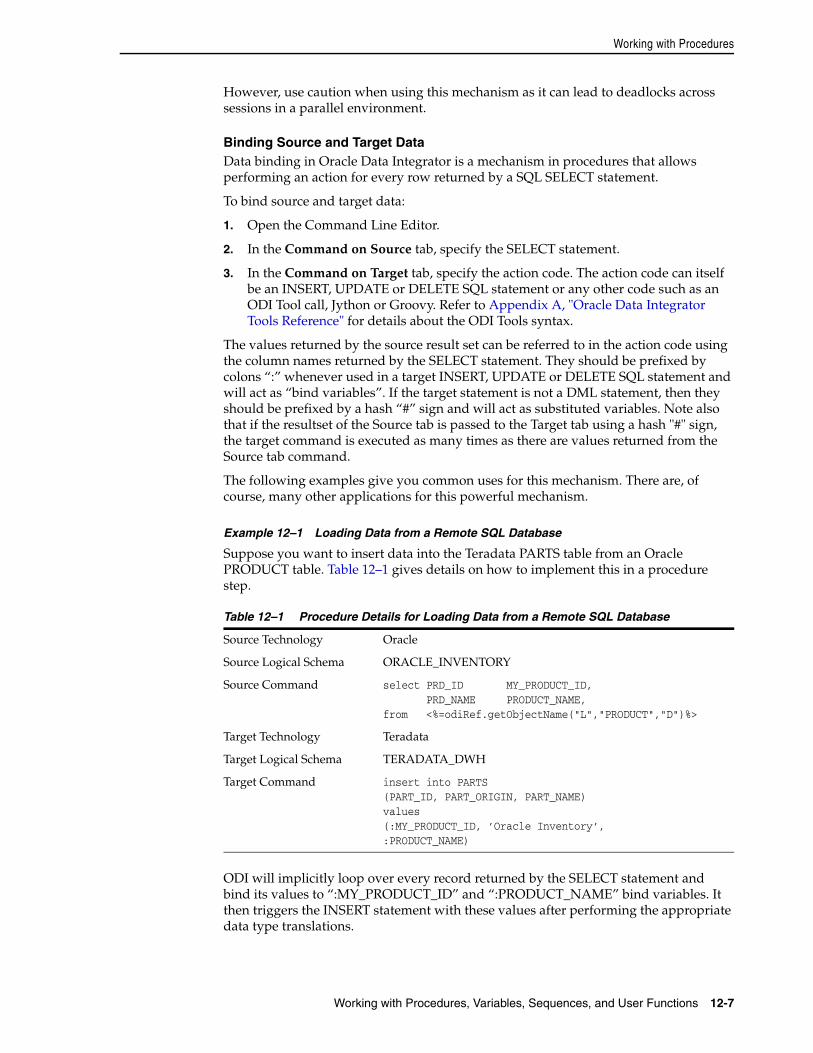
Working with Procedures
Working with Procedures, Variables, Sequences, and User Functions 12-7
However, use caution when using this mechanism as it can lead to deadlocks across sessions in a parallel environment.
Binding Source and Target DataData binding in Oracle Data Integrator is a mechanism in procedures that allows performing an action for every row returned by a SQL SELECT statement.
To bind source and target data:
1. Open the Command Line Editor.
2. In the Command on Source tab, specify the SELECT statement.
3. In the Command on Target tab, specify the action code. The action code can itself be an INSERT, UPDATE or DELETE SQL statement or any other code such as an ODI Tool call, Jython or Groovy. Refer to Appendix A, "Oracle Data Integrator Tools Reference" for details about the ODI Tools syntax.
The values returned by the source result set can be referred to in the action code using the column names returned by the SELECT statement. They should be prefixed by colons “:” whenever used in a target INSERT, UPDATE or DELETE SQL statement and will act as “bind variables”. If the target statement is not a DML statement, then they should be prefixed by a hash “#” sign and will act as substituted variables. Note also that if the resultset of the Source tab is passed to the Target tab using a hash "#" sign, the target command is executed as many times as there are values returned from the Source tab command.
The following examples give you common uses for this mechanism. There are, of course, many other applications for this powerful mechanism.
Example 12–1 Loading Data from a Remote SQL Database
Suppose you want to insert data into the Teradata PARTS table from an Oracle PRODUCT table. Table 12–1 gives details on how to implement this in a procedure step.
ODI will implicitly loop over every record returned by the SELECT statement and bind its values to “:MY_PRODUCT_ID” and “:PRODUCT_NAME” bind variables. It then triggers the INSERT statement with these values after performing the appropriate data type translations.
Table 12–1 Procedure Details for Loading Data from a Remote SQL Database
Source Technology Oracle
Source Logical Schema ORACLE_INVENTORY
Source Command select PRD_ID MY_PRODUCT_ID, PRD_NAME PRODUCT_NAME,from <%=odiRef.getObjectName("L","PRODUCT","D")%>
Target Technology Teradata
Target Logical Schema TERADATA_DWH
Target Command insert into PARTS(PART_ID, PART_ORIGIN, PART_NAME)values(:MY_PRODUCT_ID, ’Oracle Inventory’,:PRODUCT_NAME)
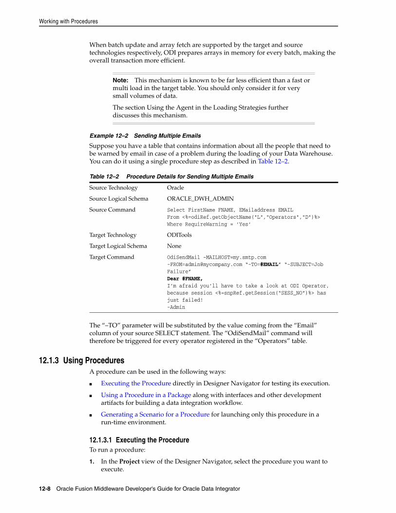
Working with Procedures
12-8 Oracle Fusion Middleware Developer's Guide for Oracle Data Integrator
When batch update and array fetch are supported by the target and source technologies respectively, ODI prepares arrays in memory for every batch, making the overall transaction more efficient.
Example 12–2 Sending Multiple Emails
Suppose you have a table that contains information about all the people that need to be warned by email in case of a problem during the loading of your Data Warehouse. You can do it using a single procedure step as described in Table 12–2.
The “–TO” parameter will be substituted by the value coming from the “Email” column of your source SELECT statement. The “OdiSendMail” command will therefore be triggered for every operator registered in the “Operators” table.
12.1.3 Using ProceduresA procedure can be used in the following ways:
■ Executing the Procedure directly in Designer Navigator for testing its execution.
■ Using a Procedure in a Package along with interfaces and other development artifacts for building a data integration workflow.
■ Generating a Scenario for a Procedure for launching only this procedure in a run-time environment.
12.1.3.1 Executing the ProcedureTo run a procedure:
1. In the Project view of the Designer Navigator, select the procedure you want to execute.
Note: This mechanism is known to be far less efficient than a fast or multi load in the target table. You should only consider it for very small volumes of data.
The section Using the Agent in the Loading Strategies further discusses this mechanism.
Table 12–2 Procedure Details for Sending Multiple Emails
Source Technology Oracle
Source Logical Schema ORACLE_DWH_ADMIN
Source Command Select FirstName FNAME, EMailaddress EMAIL From <%=odiRef.getObjectName("L","Operators","D")%>Where RequireWarning = ’Yes’
Target Technology ODITools
Target Logical Schema None
Target Command OdiSendMail -MAILHOST=my.smtp.com [email protected] “-TO=#EMAIL” “-SUBJECT=Job Failure”Dear #FNAME,I’m afraid you’ll have to take a look at ODI Operator, because session <%=snpRef.getSession(“SESS_NO”)%> has just failed!-Admin
Working with Procedures
Working with Procedures, Variables, Sequences, and User Functions 12-9
2. Right-click and select Execute.
3. In the Execution dialog, set the execution parameters. Refer to Table 20–1 for more information.
4. Click OK.
5. The Session Started Window appears.
6. Click OK.
12.1.3.2 Using a Procedure in a PackageProcedures can be used as package steps. Refer to the Section 10.3.1.2, "Executing a Procedure" for more information on how to execute a procedure in a package step. Note that if you use a procedure in a package step, the procedure is not a copy of the procedure you created but a link to it. If this procedure is modified outside of the package, the package using the procedure will be changed, too.
12.1.3.3 Generating a Scenario for a ProcedureIt is possible to generate a scenario to run a procedure in production environment, or to schedule its execution without having to create a package using this procedure. The generated scenario will be a scenario with a single step running this procedure. How to generate a scenario for a procedure is covered in Section 13.2, "Generating a Scenario".
12.1.4 Encrypting and Decrypting ProceduresEncrypting a Knowledge Module (KM) or a procedure allows you to protect valuable code. An encrypted KM or procedure can neither be read nor modified if it is not decrypted. The commands generated in the log by an Encrypted KM or procedure are also unreadable.
Oracle Data Integrator uses a DES Encryption algorithm based on a personal encryption key. This key can be saved in a file and reused to perform encryption or decryption operations.
12.1.4.1 Encrypting a KM or ProcedureTo encrypt a KM or a Procedure:
1. Right-click the KM or procedure you wish to encrypt.
2. Select Encrypt.
Note: During this execution the Procedure uses the option values set on the Options tab of the Procedure editor.
Note: If you don’t want to use the option values set on the Options tab of the Procedure, set the new options values directly in the Options tab of the Procedure step.
WARNING: There is no way to decrypt an encrypted KM or procedure without the encryption key. It is therefore strongly advised to keep this key in a safe location. It is also advised to use a unique key for all the developments.
Working with Variables
12-10 Oracle Fusion Middleware Developer's Guide for Oracle Data Integrator
3. In the Encryption Option dialog, either:
■ Select the Encrypt with a personal key option and select an existing Encryption Key file
■ Select the Encrypt with a personal key option and then type in (or paste) the string corresponding to your personal key
■ or let Oracle Data Integrator generate a key using the Get a new encryption key option.
4. The Encryption Key dialog appears when the encryption is finished. From this dialog, you can save the key.
Note that if you type in a personal key with too few characters, an invalid key size error appears. In this case, please type in a longer personal key. A personal key of 10 or more characters is required.
12.1.4.2 Decrypting a KM or ProcedureTo decrypt a KM or a procedure:
1. Right-click the KM or procedure that you wish to decrypt.
2. Select Decrypt.
3. In the KM/Procedure Decryption dialog, either:
■ Select an existing encryption key file
■ or type in (or paste) the string corresponding to your personal key.
A message appears when the decryption has finished.
12.2 Working with VariablesThis section provides an introduction to variables and describes how to create and use variables in Oracle Data Integrator.
12.2.1 Introduction to VariablesA variable is an object that stores a single value. This value can be a string, a number or a date. The variable value is stored in Oracle Data Integrator. It can be used in several places in your projects, and its value can be updated at run-time.
Depending on the variable type, a variable can have the following characteristics:
■ It has a default value defined at creation time.
■ Its value can be passed as a parameter when running a scenario using the variable.
■ Its value can be refreshed with the result of a statement executed on one of your data servers. For example, it can retrieve the current date and time from a database.
■ Its value can be set or incremented in package steps.
■ It can be evaluated to create conditions and branches in packages.
■ It can be used in the expressions and code of interfaces, procedures, steps,...
Variables can be used in any expression (SQL or others), as well as within the metadata of the repository. A variable is resolved when the command containing it is executed by the agent or the graphical interface.
Working with Variables
Working with Procedures, Variables, Sequences, and User Functions 12-11
A variable can be created as a global variable or in a project. This defines the variable scope. Global variables can be used in all projects, while project variables can only be used within the project in which they are defined.
The variable scope is detailed in Section 12.2.3, "Using Variables".
The following section describes how to create and use variables.
12.2.2 Creating VariablesTo create a variable:
1. In Designer Navigator select the Variables node in a project or the Global Variables node in the Others view.
2. Right-click and select New Variable. The Variable Editor opens.
3. Specify the following variable parameters:
4. If you want the variable's value to be set by a query:
1. Select the Refreshing tab.
2. Select the logical Schema where the command will be executed, then edit the command text in the language of the schema's technology. You can use the Expression Editor for editing the command text. It is recommended to use
Properties Description
Name Name of the variable, in the form it will be used. This name should not contain characters that could be interpreted as word separators (blanks, etc.) by the technologies the variable will be used on. Variable names are not case-sensitive. That is, "YEAR" and "year" are considered to be the same variables. The variable name is limited to a length of 400 characters.
Datatype Type of variable:
■ Alphanumeric (255 characters)
■ Date (This format is a Java date format that matches your machine's local parameters. Note that you may need to adapt the format depending to the RDBMS)
■ Numeric (Maximum 10 digits)
■ Text (Unlimited length)
Action This parameter shows the length of time the value of a variable is kept for:
■ Non-persistent: The value of the variable is kept in memory for a whole session.
■ Last value: Oracle Data Integrator stores in its repository the latest value held by the variable.
■ Historize: Oracle Data Integrator keeps a history of all the values held by this variable. Use this option if you want to keep a history of the variable values or for debugging purposes.
Note that Historize should be used selectively as the variable history is not automatically purged and grows each time the variable is used. Using history for many variables has an impact on the size of the work repository.
Default Value The value assigned to the variable by default.
Description Detailed description of the variable
Working with Variables
12-12 Oracle Fusion Middleware Developer's Guide for Oracle Data Integrator
Substitution methods such as getObjectName in the syntax of your query expression.
3. Click Testing query on the DBMS to check the syntax of your expression.
4. Click Refresh to test the variable by executing the query immediately. If the variable action is set to Historize or Latest Value, you can view the returned value on the History tab of the Variable editor.
5. From the File menu, click Save.
The variable appears in the Projects or Others tree in Designer Navigator.
12.2.3 Using VariablesUsing Variables is highly recommended to create reusable packages or packages with a complex conditional logic, interfaces and procedures. Variables can be used everywhere within ODI. Their value can be stored persistently in the ODI Repository if their action type is set to “Historize” or “Last Value”. Otherwise, with an action type of “Non-Persistent”, their value will only be kept in the memory of the agent during the execution of the current session.
This section provides an overview of how to use variables in Oracle Data Integrator. Variables can be used in the following cases:
■ Using Variables in Packages
■ Using Variables in Interfaces
■ Using Variables in Object Properties
■ Using Variables in Procedures
■ Using Variables within Variables
■ Using Variables in the Resource Name of a Datastore
■ Passing a Variable to a Scenario
■ Generating a Scenario for a Variable
Variable scopeUse the Expression editor to refer to your variables in Packages, integration interfaces, and procedures. When you use the Expression editor the variables are retrieved directly from the repository.
You should only manually prefix variable names with GLOBAL or the PROJECT_CODE, when the Expression editor is not available.
Referring to variable MY_VAR in your objects should be done as follows:
■ #MY_VAR: With this syntax, the variable must be in the same project as the object referring to it. Its value will be substituted. To avoid ambiguity, consider using fully qualified syntax by prefixing the variable name with the project code.
Note: It is advised to use the Expression editor when you refer to variables. By using the Expression editor, you can avoid the most common syntax errors. For example, when selecting a variable in the Expression editor, the variable name will be automatically prefixed with the correct code depending on the variable scope. Refer to Variable scope for more information on how to refer to your variables.
Working with Variables
Working with Procedures, Variables, Sequences, and User Functions 12-13
■ #MY_PROJECT_CODE.MY_VAR: Using this syntax allows you to use variables by explicitly stating the project that contains the variable. It prevents ambiguity when 2 variables with the same name exist for example at global and project level. The value of the variable will be substituted at runtime.
■ #GLOBAL.MY_VAR: This syntax allows you to refer to a global variable. Its value will be substituted in your code. Refer to section Global Objects for details.
■ Using “:” instead of “#”: You can use the variable as a SQL bind variable by prefixing it with a colon rather than a hash. However this syntax is subject to restrictions as it only applies to SQL DML statements, not for OS commands or ODI API calls and using the bind variable may result in performance loss. It is advised to use ODI variables prefixed with the '#'character to ensure optimal performance at runtime.
– When you reference an ODI Variable prefixed with the ':' character, the name of the Variable is NOT substituted when the RDBMS engine determines the execution plan. The variable is substituted when the RDBMS executes the request. This mechanism is called Binding. If using the binding mechanism, it is not necessary to enclose the variables which store strings into delimiters (such as quotes) because the RDBMS is expecting the same type of data as specified by the definition of the column for which the variable is used.
For example, if you use the variable TOWN_NAME = :GLOBAL.VAR_TOWN_NAME the VARCHAR type is expected.
– When you reference an ODI variable prefixed with the "#" character, ODI substitutes the name of the variable by the value before the code is executed by the technology. The variable reference needs to be enclosed in single quote characters, for example TOWN = '#GLOBAL.VAR_TOWN'. The call of the variable works for OS commands, SQL, and ODI API calls.
12.2.3.1 Using Variables in PackagesVariables can be used in packages for different purposes:
■ Declaring a variable: When a variable is used in a package (or in certain elements of the topology that are used in the package), it is strongly recommended that you insert a Declare Variable step in the packaget. This step explicitly declares the variable in the package. How to create a Declare Variable step is covered in "Declaring a Variable". Other variables that you explicitly use in your packages for setting, refreshing or evaluating their values do not need to be declared.
■ Refreshing a variable from its SQL SELECT statement: A Refresh Variable step allows you to re-execute the command or query that computes the variable value. How to create a Refresh Variable step is covered in "Refreshing a Variable".
■ Assigning the value of a variable: A Set Variable step of type Assign sets the current value of a variable.
In Oracle Data Integrator you can assign a value to a variable in the following ways:
– Retrieving the variable value from a SQL SELECT statement: When creating your variable, define a SQL statement to retrieve its value. For example, you can create a variable NB_OF_OPEN_ORDERS and set its SQL statement to: select COUNT(*) from <%=odiRef.getObjectName("L","ORDERS","D")%> where STATUS = ‘OPEN’.
Working with Variables
12-14 Oracle Fusion Middleware Developer's Guide for Oracle Data Integrator
Then in your package, you will simply drag and drop your variable and select the “Refresh Variable” option in the Properties panel. At runtime, the ODI agent will execute the SQL statement and assign the first returned value of the result set to the variable.
– Explicitly setting the value in a package: You can also manually assign a value to your variable for the scope of your package. Simply drag and drop your variable into your package and select the “Set Variable” and “Assign” options in the Properties panel as well as the value you want to set.
– Incrementing the value: Incrementing only applies to variables defined with a numeric data type. Drag and drop your numeric variable into the package and select the “Set Variable” and “Assign” options in the Properties panel as well as the desired increment. Note that the increment value can be positive or negative.
– Assigning the value at runtime: When you start a scenario generated from a package containing variables, you can set the values of its variables. You can do that in the StartScenario command by specifying the VARIABLE=VALUE list. Refer to the OdiStartLoadPlan API command and the section Section 20.3.2, "Executing a Scenario from a Command Line".
How to create a Assign Variable step is covered in "Setting a Variable".
■ Incrementing a numeric value: A Set Variable step of type Increment increases or decreases a numeric value by the specified amount. How to create a Set Variable step is covered in "Setting a Variable".
■ Evaluating the value for conditional branching: An Evaluate Variable step acts like an IF-ELSE step. It tests the current value of a variable and branches in a package depending on the result of the comparison. For example, you can choose to execute interfaces A and B of your package only if variable EXEC_A_AND_B is set to “YES”, otherwise you would execute interfaces B and C. To do this, you would simply drag and drop the variable in your package diagram, and select the “Evaluate Variable” type in the properties panel. Evaluating variables in a package allows great flexibility in designing reusable, complex workflows. How to create an Evaluate Variable step is covered in Evaluating a Variable.
12.2.3.2 Using Variables in InterfacesVariables can be used in interfaces in two different ways:
1. As a value for a textual option of a Knowledge Module.
2. In all Oracle Data Integrator expressions such as mappings, filters, joins, and constraints.
To substitute the value of the variable into the text of an expression, precede its name by the '#' character. The agent or the graphical interface will substitute the value of the variable in the command before executing it.
The following example shows the use of a global variable named 'YEAR':
Update CLIENT set LASTDATE = sysdate where DATE_YEAR = '#GLOBAL.YEAR' /* DATE_YEAR is CHAR type */Update CLIENT set LASTDATE = sysdate where DATE_YEAR = #GLOBAL.YEAR /* DATE_YEAR is NUMERIC type */
The "bind variable" mechanism of the SQL language can also be used, however, this is less efficient, because the relational database engine does not know the value of the variable when it constructs the execution plan for the query. To use this mechanism,
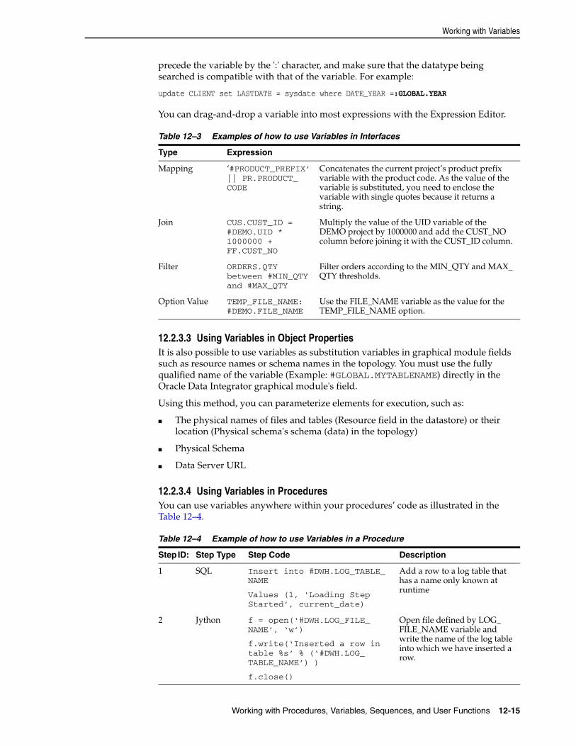
Working with Variables
Working with Procedures, Variables, Sequences, and User Functions 12-15
precede the variable by the ':' character, and make sure that the datatype being searched is compatible with that of the variable. For example:
update CLIENT set LASTDATE = sysdate where DATE_YEAR =:GLOBAL.YEAR
You can drag-and-drop a variable into most expressions with the Expression Editor.
12.2.3.3 Using Variables in Object PropertiesIt is also possible to use variables as substitution variables in graphical module fields such as resource names or schema names in the topology. You must use the fully qualified name of the variable (Example: #GLOBAL.MYTABLENAME) directly in the Oracle Data Integrator graphical module's field.
Using this method, you can parameterize elements for execution, such as:
■ The physical names of files and tables (Resource field in the datastore) or their location (Physical schema's schema (data) in the topology)
■ Physical Schema
■ Data Server URL
12.2.3.4 Using Variables in ProceduresYou can use variables anywhere within your procedures’ code as illustrated in the Table 12–4.
Table 12–3 Examples of how to use Variables in Interfaces
Type Expression
Mapping ‘#PRODUCT_PREFIX’ || PR.PRODUCT_CODE
Concatenates the current project’s product prefix variable with the product code. As the value of the variable is substituted, you need to enclose the variable with single quotes because it returns a string.
Join CUS.CUST_ID = #DEMO.UID * 1000000 + FF.CUST_NO
Multiply the value of the UID variable of the DEMO project by 1000000 and add the CUST_NO column before joining it with the CUST_ID column.
Filter ORDERS.QTY between #MIN_QTY and #MAX_QTY
Filter orders according to the MIN_QTY and MAX_QTY thresholds.
Option Value TEMP_FILE_NAME: #DEMO.FILE_NAME
Use the FILE_NAME variable as the value for the TEMP_FILE_NAME option.
Table 12–4 Example of how to use Variables in a Procedure
Step ID: Step Type Step Code Description
1 SQL Insert into #DWH.LOG_TABLE_NAME
Values (1, ‘Loading Step Started’, current_date)
Add a row to a log table that has a name only known at runtime
2 Jython f = open(‘#DWH.LOG_FILE_NAME’, ‘w’)
f.write(‘Inserted a row in table %s’ % (‘#DWH.LOG_TABLE_NAME’) )
f.close()
Open file defined by LOG_FILE_NAME variable and write the name of the log table into which we have inserted a row.
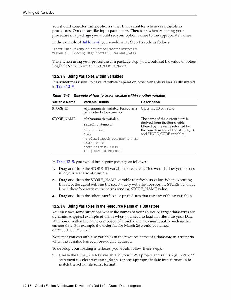
Working with Variables
12-16 Oracle Fusion Middleware Developer's Guide for Oracle Data Integrator
You should consider using options rather than variables whenever possible in procedures. Options act like input parameters. Therefore, when executing your procedure in a package you would set your option values to the appropriate values.
In the example of Table 12–4, you would write Step 1’s code as follows:
Insert into <%=snpRef.getOption(“LogTableName”)%> Values (1, ‘Loading Step Started’, current_date)
Then, when using your procedure as a package step, you would set the value of option LogTableName to #DWH.LOG_TABLE_NAME.
12.2.3.5 Using Variables within VariablesIt is sometimes useful to have variables depend on other variable values as illustrated in Table 12–5.
In Table 12–5, you would build your package as follows:
1. Drag and drop the STORE_ID variable to declare it. This would allow you to pass it to your scenario at runtime.
2. Drag and drop the STORE_NAME variable to refresh its value. When executing this step, the agent will run the select query with the appropriate STORE_ID value. It will therefore retrieve the corresponding STORE_NAME value.
3. Drag and drop the other interfaces or procedures that use any of these variables.
12.2.3.6 Using Variables in the Resource Name of a DatastoreYou may face some situations where the names of your source or target datastores are dynamic. A typical example of this is when you need to load flat files into your Data Warehouse with a file name composed of a prefix and a dynamic suffix such as the current date. For example the order file for March 26 would be named ORD2009.03.26.dat.
Note that you can only use variables in the resource name of a datastore in a scenario when the variable has been previously declared.
To develop your loading interfaces, you would follow these steps:
1. Create the FILE_SUFFIX variable in your DWH project and set its SQL SELECT statement to select current_date (or any appropriate date transformation to match the actual file suffix format)
Table 12–5 Example of how to use a variable within another variable
Variable Name Variable Details Description
STORE_ID Alphanumeric variable. Passed as a parameter to the scenario
Gives the ID of a store
STORE_NAME Alphanumeric variable.
SELECT statement:
Select nameFrom <%=odiRef.getObjectName("L","STORES","D")%>Where id=‘#DWH.STORE_ID’||’#DWH.STORE_CODE’
The name of the current store is derived from the Stores table filtered by the value returned by the concatenation of the STORE_ID and STORE_CODE variables.
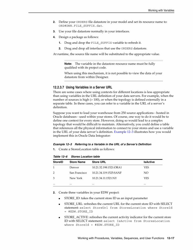
Working with Variables
Working with Procedures, Variables, Sequences, and User Functions 12-17
2. Define your ORDERS file datastore in your model and set its resource name to: ORD#DWH.FILE_SUFFIX.dat.
3. Use your file datastore normally in your interfaces.
4. Design a package as follows:
1. Drag and drop the FILE_SUFFIX variable to refresh it.
2. Drag and drop all interfaces that use the ORDERS datastore.
At runtime, the source file name will be substituted to the appropriate value.
12.2.3.7 Using Variables in a Server URLThere are some cases where using contexts for different locations is less appropriate than using variables in the URL definition of your data servers. For example, when the number of sources is high (> 100), or when the topology is defined externally in a separate table. In these cases, you can refer to a variable in the URL of a server’s definition.
Suppose you want to load your warehouse from 250 source applications - hosted in Oracle databases - used within your stores. Of course, one way to do it would be to define one context for every store. However, doing so would lead to a complex topology that would be difficult to maintain. Alternatively, you could define a table that references all the physical information to connect to your stores and use a variable in the URL of your data server’s definition. Example 12–3 illustrates how you would implement this in Oracle Data Integrator:
Example 12–3 Referring to a Variable in the URL of a Server’s Definition
1. Create a StoresLocation table as follows:
2. Create three variables in your EDW project:
■ STORE_ID: takes the current store ID as an input parameter
■ STORE_URL: refreshes the current URL for the current store ID with SELECT statement: select StoreUrl from StoresLocation where StoreId = #EDW.STORE_ID
■ STORE_ACTIVE: refreshes the current activity indicator for the current store ID with SELECT statement: select IsActive from StoresLocation where StoreId = #EDW.STORE_ID
Note: The variable in the datastore resource name must be fully qualified with its project code.
When using this mechanism, it is not possible to view the data of your datastore from within Designer.
Table 12–6 Stores Location table
StoreID Store Name Store URL IsActive
1 Denver 10.21.32.198:1521:ORA1 YES
2 San Francisco 10.21.34.119:1525:SANF NO
3 New York 10.21.34.11:1521:NY YES
... ... ... ...
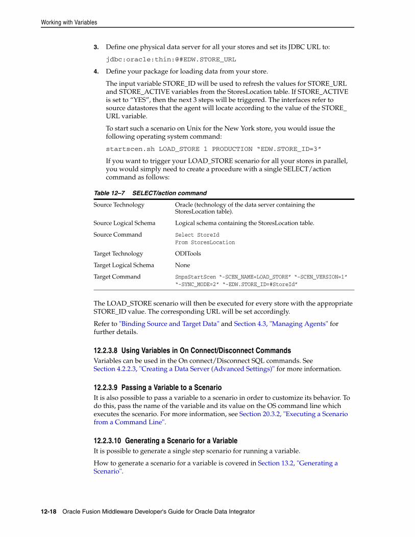
Working with Variables
12-18 Oracle Fusion Middleware Developer's Guide for Oracle Data Integrator
3. Define one physical data server for all your stores and set its JDBC URL to:
jdbc:oracle:thin:@#EDW.STORE_URL
4. Define your package for loading data from your store.
The input variable STORE_ID will be used to refresh the values for STORE_URL and STORE_ACTIVE variables from the StoresLocation table. If STORE_ACTIVE is set to “YES”, then the next 3 steps will be triggered. The interfaces refer to source datastores that the agent will locate according to the value of the STORE_URL variable.
To start such a scenario on Unix for the New York store, you would issue the following operating system command:
startscen.sh LOAD_STORE 1 PRODUCTION “EDW.STORE_ID=3”
If you want to trigger your LOAD_STORE scenario for all your stores in parallel, you would simply need to create a procedure with a single SELECT/action command as follows:
The LOAD_STORE scenario will then be executed for every store with the appropriate STORE_ID value. The corresponding URL will be set accordingly.
Refer to "Binding Source and Target Data" and Section 4.3, "Managing Agents" for further details.
12.2.3.8 Using Variables in On Connect/Disconnect CommandsVariables can be used in the On connect/Disconnect SQL commands. See Section 4.2.2.3, "Creating a Data Server (Advanced Settings)" for more information.
12.2.3.9 Passing a Variable to a ScenarioIt is also possible to pass a variable to a scenario in order to customize its behavior. To do this, pass the name of the variable and its value on the OS command line which executes the scenario. For more information, see Section 20.3.2, "Executing a Scenario from a Command Line".
12.2.3.10 Generating a Scenario for a VariableIt is possible to generate a single step scenario for running a variable.
How to generate a scenario for a variable is covered in Section 13.2, "Generating a Scenario".
Table 12–7 SELECT/action command
Source Technology Oracle (technology of the data server containing the StoresLocation table).
Source Logical Schema Logical schema containing the StoresLocation table.
Source Command Select StoreIdFrom StoresLocation
Target Technology ODITools
Target Logical Schema None
Target Command SnpsStartScen “-SCEN_NAME=LOAD_STORE” “-SCEN_VERSION=1” “-SYNC_MODE=2” “-EDW.STORE_ID=#StoreId”
Working with Sequences
Working with Procedures, Variables, Sequences, and User Functions 12-19
12.3 Working with SequencesThis section provides an introduction to sequences and describes how to create and use sequences in Oracle Data Integrator.
12.3.1 Introduction to SequencesA Sequence is a variable that increments itself automatically each time it is used. Between two uses, the value can be stored in the repository or managed within an external RDBMS table. Sequences can be strings, lists, tuples or dictionaries.
Oracle Data Integrator sequences are intended to map native sequences from RDBMS engines, or to simulate sequences when they do not exist in the RDBMS engine. Non-native sequences’ values can be stored in the Repository or managed within a cell of an external RDBMS table.
A sequence can be created as a global sequence or in a project. Global sequences are common to all projects, whereas project sequences are only available in the project where they are defined.
Oracle Data Integrator supports three types of sequences:
■ Standard sequences, whose current values ares stored in the Repository.
■ Specific sequences, whose current values are stored in an RDBMS table cell. Oracle Data Integrator reads the value, locks the row (for concurrent updates) and updates the row after the last increment.
■ Native sequence, that maps a RDBMS-managed sequence.
Note the following on standard and specific sequences:
■ Oracle Data Integrator locks the sequence when it is being used for multi-user management, but does not handle the sequence restart points. In other words, the SQL statement ROLLBACK does not return the sequence to its value at the beginning of the transaction.
■ Oracle Data Integrator standard and specific sequences were developed to compensate for their absence on some RDBMS. If native sequences exist, they should be used. This may prove to be faster because it reduces the dialog between the agent and the database.
The following sections describe how to create and use sequences.
12.3.2 Creating SequencesThe procedure for creating sequences vary depending on the sequence type. Refer to the corresponding section:
■ Creating Standard Sequences
■ Creating Specific Sequences
■ Creating Native Sequences
12.3.2.1 Creating Standard SequencesTo create a standard sequence:
1. In Designer Navigator select the Sequences node in a project or the Global Sequences node in the Others view.
2. Right-click and select New Sequence. The Sequence Editor opens.
Working with Sequences
12-20 Oracle Fusion Middleware Developer's Guide for Oracle Data Integrator
3. Enter the sequence Name, then select Standard Sequence.
4. Enter the Increment.
5. From the File menu, click Save.
The sequence appears in the Projects or Others tree in Designer Navigator.
12.3.2.2 Creating Specific SequencesSelect this option for storing the sequence value in a table in a given data schema.
To create a specific sequence:
1. In Designer Navigator select the Sequences node in a project or the Global Sequences node in the Others view.
2. Right-click and select New Sequence. The Sequence Editor opens.
3. Enter the sequence Name, then select Specific Sequence.
4. Enter the Increment value.
5. Specify the following sequence parameters:
6. From the File menu, click Save.
The sequence appears in the Projects or Others tree in Designer Navigator.
12.3.2.3 Creating Native SequencesSelect this option if your sequence is implemented in the database engine. Position and increment are fully handled by the database engine.
To create a native sequence:
1. In Designer Navigator select the Sequences node in a project or the Global Sequences node in the Others view.
2. Right-click and select New Sequence. The Sequence Editor opens.
3. Enter the sequence Name, then select Native Sequence.
4. Select the logical Schema containing your native sequence.
Schema Logical schema containing the sequences table
Table Table containing the sequence value
Column Name of the column containing the sequence value.
Filter to retrieve a single row
Type in a Filter which will allow Oracle Data Integrator to locate a specific row in the table when the sequence table contains more than one row. This filter picks up the SQL syntax of the data server.
For example: CODE_TAB = '3'
You can use the Expression Editor to edit the filter. Click Testing query on the DBMS to check the syntax of your expression.
Note: When Oracle Data Integrator wants to access the specific sequence value, the query executed on the schema will be SELECT column FROM table WHERE filter.
Working with Sequences
Working with Procedures, Variables, Sequences, and User Functions 12-21
5. Type in the Native Sequence Name or click the browse button to select a sequence from the list pulled from the data server.
6. If you clicked the Browse button, in the Native Sequence Choice dialog, select a Context to display the list of sequences in this context for your logical schema.
7. Select one of these sequences and click OK.
8. From the File menu, click Save.
The sequence appears in the Projects or Others tree in Designer Navigator.
12.3.3 Using Sequences and Identity ColumnsIn order to increment sequences, the data needs to be processed row-by-row by the agent. Therefore, using sequences is not recommended when dealing with large numbers of records. In this case, you would use database-specific sequences such as identity columns in Teradata, IBM DB2, Microsoft SQL Server or sequences in Oracle.
The sequences can be used in all Oracle Data Integrator expressions, such as in:
■ Mappings,
■ Filters,
■ Joins,
■ Constraints,
■ ...
Sequences can be used either as:
■ A substituted value, using the #<SEQUENCE_NAME>_NEXTVAL syntax
■ A bind variable in SQL statements, using the :<SEQUENCE_NAME>_NEXTVAL syntax
Using a sequence as a substituted valueA sequence can be used in all statements with the following syntax: #<SEQUENCE_NAME>_NEXTVAL
With this syntax, the sequence value is incremented only once before the command is run and then substituted by its valued into the text of the command. The sequence value is the same for all records.
Using a sequence as a bind variableOnly for SQL statements on a target command of a KM or procedure, sequences can be used with the following syntax: :<SEQUENCE_NAME>_NEXTVAL
With this syntax, the sequence value is incremented, then passed as a bind variable of the target SQL command. The sequence value is incremented in each record processed by the command. The behavior differs depending on the sequence type:
■ Native sequences are always incremented for each processed record.
■ Standard and specific sequences are resolved by the run-time agent and are incremented only when records pass through the agent. The command in a KM or procedure that uses such a sequence must use a SELECT statement on the source command and an INSERT or UPDATE statement on the target command rather than a single INSERT/UPDATE... SELECT in the target command.
For example:
Working with Sequences
12-22 Oracle Fusion Middleware Developer's Guide for Oracle Data Integrator
■ In the SQL statement insert into fac select :NO_FAC_NEXTVAL, date_fac, mnt_fac the value of a standard or specific sequence will be incremented only once, even if the SQL statement processes 10,000 rows, because the agent does not process each record, but just sends the command to the database engine. A native sequence will be incremented for each row.
■ To increment the value of a standard or specific sequence for each row, the data must pass through the agent. To do this, use a KM or procedure that performs a SELECT on the source command and an INSERT on the target command:
SELECT date_fac, mnt_fac /* on the source connection */
INSERT into FAC (ORDER_NO, ORDER_DAT, ORDER_AMNT) values (:NO_FAC_NEXTVAL, :date_fac, :mnt_fac) /* on the target connection */
Sequence ScopeUnlike for variables, you do not need to state the scope of sequences explicitly in code.
12.3.3.1 Tips for Using Standard and Specific SequencesTo make sure that a sequence is updated for each row inserted into a table, each row must be processed by the Agent. To make this happen, follow the steps below:
1. Make the mapping containing the sequence be executed on the target.
2. Set the mapping to be active for inserts only. Updates are not supported for sequences.
3. If you are using an "incremental update" IKM, you should make sure that the update key in use does not contain a column populated with the sequence. For example, if the sequence is used to load the primary key for a datastore, you should use an alternate key as the update key for the interface.
4. If using Oracle Data Integrator sequences with bind syntax (:<SEQUENCE_NAME>_NEXTVAL), you must configure the data flow such that the IKM transfers all the data through the agent. You can verify this by checking the generated integration step in Operator. It should have separate INSERT and SELECT commands executed on different connections, rather than a single SELECT...INSERT statement.
Limitations of SequencesSequences have the following limitations:
■ A column mapped with a sequence should not be checked for not null.
■ Similarly, static control and flow control cannot be performed on a primary or alternate key that references the sequence.
12.3.3.2 Identity ColumnsCertain databases also natively provide identity columns, which are automatically populated with unique, self-incrementing values.
When populating an identity column, you should follow these steps:
1. The mapping loading the identity column should be blank and inactive. It should not be activated for inserts or updates.
Working with User Functions
Working with Procedures, Variables, Sequences, and User Functions 12-23
2. If you are using "incremental update" IKMs, make sure that the update key in use does not contain the identity column. If the identity column is part of the primary key, you should define an alternate key as the update key for the interface.
Limitations of Identity ColumnsIdentity columns have the following limitations:
■ Not null cannot be checked for an identity column.
■ Static and flow control cannot be performed on a primary or alternate key containing the identity column.
12.4 Working with User FunctionsThis section provides an introduction to user functions and describes how to create and use user functions in Oracle Data Integrator.
12.4.1 Introduction User FunctionsUser functions are used for defining customized functions that can be used in interfaces or procedures. It is recommended to use them in your projects when the same complex transformation pattern needs to be assigned to different datastores within different interfaces. User functions improve code sharing and reusability and facilitate the maintenance and the portability of your developments across different target platforms.
User functions are implemented in one or more technologies and can be used anywhere in mappings, joins, filters and conditions. Refer to Section 12.4.3, "Using User Functions".
A function can be created as a global function or in a project. In the first case, it is common to all projects, and in the second, it is attached to the project in which it is defined.
User functions can call other user functions. A user function cannot call itself recursively.
The following sections describe how to create and use user functions.
12.4.2 Creating User FunctionsTo create a user function:
1. In Designer Navigator select the User Functions node in a project or the Global User Functions node in the Others view.
2. Right-click and select New User Function. The User Function Editor opens.
3. Fill in the following fields:
■ Name: Name of the user function, for example NullValue
Note: Aggregate functions are not supported User Functions. The aggregate function code will be created, but the GROUP BY expression will not be generated.
Working with User Functions
12-24 Oracle Fusion Middleware Developer's Guide for Oracle Data Integrator
■ Group: Group of the user function. If you type a group name that does not exist, a new group will be created with this group name when the function is saved.
■ Syntax: Syntax of the user function that will appear in the expression Editor; The arguments of the function must be specified in this syntax, for example NullValue($(variable), $(default))
4. From the File menu, click Save.
The function appears in the Projects or Others tree in Designer Navigator. Since it has no implementation, it is unusable.
To create an implementation:
1. In Designer Navigator double-click the User Function for which you want to create the implementation. The User Function Editor opens.
2. In the Implementations tab of the User Function Editor, click Add Implementation. The Implementation dialog opens.
3. In the Implementation syntax field, type the code of the implementation, for example nvl($(variable), $(default))
4. Check the boxes for the implementation's Linked technologies
5. Check Automatically include new technologies if you want the new technologies to use this syntax.
6. Click OK.
7. From the File menu, click Save.
To change an implementation:
1. In the Implementations tab of the User Function Editor, select an implementation, then click Edit.
2. In the Implementations tab of the user function, select an implementation, then click Edit Implementation. The Implementation dialog opens.
3. Change the Implementation syntax and the Linked technologies of this implementation
4. Check Automatically include new technologies if you want the new technologies to use this syntax.
5. Click OK.
6. From the File menu, click Save.
To remove an implementation:
In the implementations tab of the user function, select an implementation, then click Delete Implementation.
12.4.3 Using User FunctionsThe user functions can be used in all Oracle Data Integrator expressions:
■ Mappings,
■ Filters,
■ Joins,
■ Constraints,
Working with User Functions
Working with Procedures, Variables, Sequences, and User Functions 12-25
■ ...
A user function can be used directly by specifying its syntax, for example: NullValue(CITY_NAME, 'No City')
User functions are implemented in one or more technologies. For example, the Oracle nvl(VARIABLE,DEFAULT_VALUE), function - which returns the value of VARIABLE, or DEFAULT_VALUE if VARIABLE is null - has no equivalent in all technologies and must be replaced by the formula:
case when VARIABLE is nullthen DEFAULT_VALUEelse VARIABLEend
With user functions, it is possible to declare a function called NullValue(VARIABLE,DEFAULT_VALUE) and to define two implementations for the syntax above. When executing, depending on the technology on which the order will be executed, the NullValue function will be replaced by one syntax or the other.
The next example illustrates how to implement a user function that would be translated into code for different technologies:
Suppose you want to define a function that, given a date, gives you the name of the month. You want this function to be available for your mappings when executed on Oracle, Teradata or Microsoft SQL Server. Table 12–8 shows how to implement this as a user function.
You can now use this function safely in your interfaces for building your mappings, filters and joins. Oracle Data Integrator will generate the appropriate code depending on the execution location of your expression.
Another example of a user function translated into code for different technologies is defining the following mapping:
Table 12–8 User Function Translated into Code for Different Technologies (Example 1)
Function Name GET_MONTH_NAME
Function Syntax GET_MONTH_NAME($(date_input))
Description Retrieves the month name from a date provided as date_input
Implementation for Oracle
Initcap(to_char($(date_input), 'MONTH'))
Implementation for Teradata
case when extract(month from $(date_input)) = 1 then ‘January’when extract(month from $(date_input)) = 2 then ‘February’when extract(month from $(date_input)) = 3 then ‘March’when extract(month from $(date_input)) = 4 then ‘April’when extract(month from $(date_input)) = 5 then ‘May’when extract(month from $(date_input)) = 6 then ‘June’when extract(month from $(date_input)) = 7 then ‘July’when extract(month from $(date_input)) = 8 then ‘August’when extract(month from $(date_input)) = 9 then ‘September’when extract(month from $(date_input)) = 10 then ‘October’when extract(month from $(date_input)) = 11 then ‘November’when extract(month from $(date_input)) = 12 then ‘December’end
Implementation for Microsoft SQL
datename(month, $(date_input))
Working with User Functions
12-26 Oracle Fusion Middleware Developer's Guide for Oracle Data Integrator
substring(GET_MONTH_NAME(CUSTOMER.LAST_ORDER_DATE), 1, 3), Oracle Data Integrator will generate code similar to the following, depending on your execution technology:
A function can be created as a global function or in a project. In the first case, it is common to all projects, and in the second, it is attached to the project in which it is defined.
User functions can call other user functions.
Table 12–9 User Function Translated into Code for Different Technologies (Example 2)
Implementation for Oracle substring(Initcap(to_char(CUSTOMER.LAST_ORDER_DATE 'MONTH')) , 1, 3)
Implementation for Teradata
substring(case when extract(month from CUSTOMER.LAST_ORDER_DATE) = 1 then ‘January’when extract(month from CUSTOMER.LAST_ORDER_DATE) = 2 then ‘February’...end, 1, 3)
Implementation for Microsoft SQL
substring(datename(month, CUSTOMER.LAST_ORDER_DATE) , 1, 3)
13
Working with Scenarios 13-1
13Working with Scenarios
This chapter describes how to work with scenarios. A scenario is designed to put a source component (interface, package, procedure, variable) into production. A scenario results from the generation of code (SQL, shell, etc) for this component.
This chapter includes the following sections:
■ Section 13.1, "Introduction to Scenarios"
■ Section 13.2, "Generating a Scenario"
■ Section 13.3, "Regenerating a Scenario"
■ Section 13.4, "Generating a Group of Scenarios"
■ Section 13.5, "Exporting Scenarios"
■ Section 13.6, "Importing Scenarios in Production"
■ Section 13.7, "Encrypting and Decrypting a Scenario"
13.1 Introduction to ScenariosWhen a component is finished and tested, you can generate the scenario corresponding its actual state. This operation takes place in Designer Navigator.
The scenario code (the language generated) is frozen, and all subsequent modifications of the components which contributed to creating it will not change it in any way.
It is possible to generate scenarios for packages, procedures, interfaces or variables. Scenarios generated for procedures, interfaces or variables are single step scenarios that execute the procedure, interface or refresh the variable.
Scenario variables are variables used in the scenario that should be set when starting the scenario to parameterize its behavior.
Once generated, the scenario is stored inside the work repository. The scenario can be exported then imported to another repository (remote or not) and used in different contexts. A scenario can only be created from a development work repository, but can be imported into both development and execution work repositories.
Scenarios appear in a development environment under the source component in the Projects tree of Designer Navigator, and appear - for development and production environments - in the Scenarios tree of Operator Navigator.
Scenarios can also be versioned. See Chapter 18, "Working with Version Management" for more information.
Scenarios can be launched from a command line, from the Oracle Data Integrator Studio and can be scheduled using the built-in scheduler of the run-time agent or an
Generating a Scenario
13-2 Oracle Fusion Middleware Developer's Guide for Oracle Data Integrator
external scheduler. Scenario execution and scheduling scenarios is covered in Chapter 20, "Running Integration Processes".
13.2 Generating a ScenarioGenerating a scenario for an object compiles the code for this object for deployment and execution in a production environment.
To generate a scenario:
1. In Designer Navigator double-click the Package, Interface, Procedure or Variable under the project for which you want to generate the scenario. The corresponding Object Editor opens.
2. On the Scenarios tab, click Generate Scenario. The New Scenario dialog appears.
3. Enter the Name and the Version of the scenario. As this name can be used in an operating system command, the name is automatically uppercased and special characters are replaced by underscores.
Note that the Name and Version fields of the Scenario are preset with the following values:
– Name: The same name as the latest scenario generated for the component
– Version: The version number is automatically incremented (if the latest version is an integer) or set to the current date (if the latest version is not an integer)
If no scenario has been created yet for the component, a first version of the scenario is automatically created.
New scenarios are named after the component according to the Scenario Naming Convention user parameter. See Appendix B, "User Parameters" for more information.
4. Click OK.
5. If you use variables in the scenario, you can define in the Scenario Variables dialog the variables that will be considered as parameters for the scenario. Select Use All if you want all variables to be parameters, or Use Selected and check the parameter variables.
6. Click OK.
The scenario appears on the Scenarios tab and under the Scenarios node of the source object under the project.
13.3 Regenerating a ScenarioAn existing scenario can be regenerated with the same name and version number. This lets you replace the existing scenario by a scenario generated from the source object contents. Schedules attached to this scenario are preserved.
To regenerate a scenario:
1. Select the scenario in the Projects accordion.
2. Right-click and select Regenerate...
3. Click OK.
Generating a Group of Scenarios
Working with Scenarios 13-3
13.4 Generating a Group of ScenariosWhen a set of packages, interfaces, procedures and variables grouped under a project or folder is finished and tested, you can generate the scenarios. This operation takes place in Designer Navigator.
To generate a group of scenarios:
1. Select the Project or Folder containing the group of objects.
2. Right-click and select Generate All Scenarios...
3. In the Scenario Generation dialog, select the scenario Generation Mode:
■ Replace: Overwrites for each object the last scenario version with a new one with the same ID, name and version. Sessions, scenario reports and schedules are deleted. If no scenario exists for an object, a scenario with version number 001 is created.
■ Re-generate: Overwrites for each object the last scenario version with a new one with the same id, name and version. It preserves the schedule, sessions and scenario reports. If no scenario exists for an object, no scenario is created using this mode.
■ Creation: Creates for each object a new scenario with the same name as the last scenario version and with an automatically incremented version number. If no scenario exists for an object, a scenario named after the object with version number 001 is created.
4. In the Objects to Generate section, select the types of objects for which you want to generate scenarios.
5. In the Marker Filter section, you can filter the components to generate according to a marker from a marker group.
6. Click OK.
7. If you use variables in the scenario, you can define in the Scenario Variables dialog the variables that will be considered as parameters for the scenario. Select Use All if you want all variables to be parameters, or Use Selected and check the parameter variables.
Caution: Regenerating a scenario cannot be undone. For important scenarios, it is better to generate a scenario with a new version number.
Note: If no scenario has been created yet for the component, a first version of the scenario is automatically created.
New scenarios are named after the component according to the Scenario Naming Convention user parameter. See Appendix B, "User Parameters" for more information
If the version of the last scenario is an integer, it will be automatically incremented by 1 when selecting the Creation generation mode. If not, the version will be automatically set to the current date.
Exporting Scenarios
13-4 Oracle Fusion Middleware Developer's Guide for Oracle Data Integrator
13.5 Exporting ScenariosThe export (and import) procedure allows you to transfer Oracle Data Integrator objects from one repository to another.
It is possible to export a single scenario or groups of scenarios.
Exporting one single scenario is covered in Section 19.2.1, "Exporting one ODI Object".
To export a group of scenarios:
1. Select the Project or Folder containing the group of scenarios.
2. Right-click and select Export All Scenarios... The Export all scenarios dialog opens.
3. In the Export all scenarios dialog, specify the export parameters as follows:
4. Select the type of objects whose scenarios you want to export.
5. Set the advanced options. This set of options allow to parameterize the XML output file format. It is recommended that you leave the default values.
6. Click OK.
The XML-formatted export files are created at the specified location.
13.6 Importing Scenarios in ProductionA scenario generated from Designer can be exported and then imported into a development or execution repository. This operation is used to deploy scenarios in a different repository, possibly in a different environment or site.
Parameter Description
Export Directory Directory in which the export file will be created.
Note that if the Export Directory is not specified, the export file is created in the Default Export Directory.
Child components export If this option is checked, the objects linked to the object to be exported will be also exported. These objects are those visible under the exported object in the tree. It is recommended to leave this option checked. See Exporting an Object with its Child Components for more details.
Replace existing files without warning
If this option is checked, the existing file will be replaced by the ones of the export.
Parameter Description
XML Version XML Version specified in the export file. Parameter xml version in the XML file header.
<?xml version="1.0" encoding="ISO-8859-1"?>
Character Set Encoding specified in the export file. Parameter encoding in the XML file header.
<?xml version="1.0" encoding="ISO-8859-1"?>
Java Character Set Java character set used to generate the file.
Importing Scenarios in Production
Working with Scenarios 13-5
Importing a scenario in a development repository is performed via Designer or Operator Navigator. With a execution repository, only Operator Navigator is available for this purpose.
There are two ways to import a scenario:
■ Import uses the standard object import method. During this import process, it is possible to choose to import the schedules attached to the exported scenario.
■ Import Replace replaces an existing scenario with the content of an export file, preserving references from other objects to this scenario. Sessions, scenario reports and schedules from the original scenario are deleted and replaced with the schedules from the export file.
Scenarios can also be deployed and promoted to production using versions and solutions. See Chapter 18, "Working with Version Management" for more information.
13.6.1 Import ScenariosTo import one or more scenarios into Oracle Data Integrator:
1. In Operator Navigator, select the Scenarios panel.
2. Right-click and select Import > Import Scenario.
3. Select the Import Type. Refer to Chapter 19, "Exporting/Importing" for more information on the import modes.
4. Specify the File Import Directory.
5. Check the Import schedules option, if you want to import the schedules exported with the scenarios as well.
6. Select one or more scenarios to import from the Select the file(s) to import list.
7. Click OK.
The scenarios are imported into the work repository. They appear in the Scenarios tree of the Operator Navigator. If this work repository is a development repository, these scenario are also attached to their source Package, Interface, Procedure or Variable.
13.6.2 Replace a ScenarioUse the import replace mode if you want to replace a scenario with an exported one.
To import a scenario in replace mode:
1. In Designer or Operator Navigator, select the scenario you wish to replace.
2. Right-click the scenario, and select Import Replace...
3. In the Replace Object dialog, specify the scenario export file.
4. Click OK.
13.6.3 Working with a Scenario from a Different RepositoryA scenario may have to be operated from a different work repository than the one where it was generated.
ExamplesHere are two examples of organizations that give rise to this type of process:
Encrypting and Decrypting a Scenario
13-6 Oracle Fusion Middleware Developer's Guide for Oracle Data Integrator
■ A company has a large number of agencies equipped with the same software applications. In its IT headquarters, it develops packages and scenarios to centralize data to a central data center. These scenarios are designed to be executed identically in each agency.
■ A company has three distinct IT environments for developing, qualifying and operating its software applications. The company's processes demand total separation of the environments, which cannot share the Repository.
PrerequisitesThe prerequisite for this organization is to have a work repository installed on each environment (site, agency or environment). The topology of the master repository attached to this work repository must be compatible in terms of its logical architecture (the same logical schema names). The connection characteristics described in the physical architecture can differ.
Note that in cases where some procedures or interfaces explicitly specify a context code, the target topology must have the same context codes. The topology, that is, the physical and logical architectures, can also be exported from a development master repository, then imported into the target repositories. Use the Topology module to carry out this operation. In this case, the physical topology (the servers' addresses) should be personalized before operating the scenarios. Note also that a topology import simply references the new data servers without modifying those already present in the target repository.
To operate a scenario from a different work repository:
1. Export the scenario from its original repository (right-click, export)
2. Forward the scenario export file to the target environment
3. Open Designer Navigator in the target environment (connection to the target repository)
4. Import the scenario from the export file
13.7 Encrypting and Decrypting a ScenarioEncrypting a scenario allows you to protect valuable code. An encrypted scenario can be executed but cannot be read or modified if it is not decrypted. The commands generated in the log by an encrypted scenario are also unreadable.
Oracle Data Integrator uses a DES Encryption algorithm based on a personal encryption key. This key can be saved in a file and can be reused to perform encryption or decryption operations.
To encrypt a scenario:
1. In Designer or Operator Navigator, select the scenario you want to encrypt.
2. Right-click and select Encrypt.
3. In the Encryption Options dialog, you can either:
WARNING: There is no way to decrypt an encrypted scenario or procedure without the encryption key. It is therefore strongly advised to keep this key in a safe location.
Encrypting and Decrypting a Scenario
Working with Scenarios 13-7
■ Encrypt with a personal key that already exists by giving the location of the personal key file or by typing in the value of the personal key.
■ Get a new encryption key to have a new key generated.
4. Click OK to encrypt the scenario. If you have chosen to generate a new key, a dialog will appear with the new key. Click Save to save the key in a file.
To decrypt a scenario:
1. Right-click the scenario you want to decrypt.
2. Select Decrypt.
3. In the Scenario Decryption dialog, either
■ Select an existing encryption key file
■ or type in (or paste) the string corresponding to your personal key.
A message appears when decryption is finished.
Note: If you type in a personal key with too few characters, an invalid key size error appears. In this case, please type in a longer personal key. A personal key of 10 or more characters is required.

Encrypting and Decrypting a Scenario
13-8 Oracle Fusion Middleware Developer's Guide for Oracle Data Integrator
14
Working with Load Plans 14-1
14Working with Load Plans
This chapter gives an introduction to Load Plans. It describes how to create a Load Plan and provides information about how to work with Load Plans.
This chapter includes the following sections:
■ Section 14.1, "Introduction to Load Plans"
■ Section 14.2, "Creating a Load Plan"
■ Section 14.3, "Running Load Plans"
■ Section 14.4, "Using Load Plans in Production"
14.1 Introduction to Load PlansOracle Data Integrator is often used for populating very large data warehouses. In these use cases, it is common to have thousands of tables being populated using hundreds of scenarios. The execution of these scenarios has to be organized in such a way that the data throughput from the sources to the target is the most efficient within the batch window. Load Plans help the user organizing the execution of scenarios in a hierarchy of sequential and parallel steps for these type of use cases.
A Load Plan is an executable object in Oracle Data Integrator that can contain a hierarchy of steps that can be executed conditionally, in parallel or in series. The leaves of this hierarchy are Scenarios. Packages, interfaces, variables, and procedures can be added to Load Plans for executions in the form of scenarios. For more information, see Section 14.2, "Creating a Load Plan".
Load Plans allow setting and using variables at multiple levels. See Section 14.2.3, "Working with Variables in Load Plans" for more information. Load Plans also support exception handling strategies in the event of a scenario ending in error. See Section 14.2.4, "Handling Load Plan Exceptions and Restartability" for more information.
Load Plans can be started, stopped, and restarted from a command line, from Oracle Data Integrator Studio, Oracle Data Integrator Console or a Web Service interface. They can also be scheduled using the run-time agent’s built-in scheduler or an external scheduler. When a Load Plan is executed, a Load Plan Instance is created. Each attempt to run this Load Plan Instance is a separate Load Plan Run. See Chapter 14.3, "Running Load Plans" for more information.
A Load Plan can be modified in production environments and steps can be enabled or disabled according to the production needs. Load Plan objects can be designed and viewed in the Designer and Operator Navigators. Various design operations (such as create, edit, delete, and so forth) can be performed on a Load Plan object if a user connects to a development work repository, but some design operations will not be
Introduction to Load Plans
14-2 Oracle Fusion Middleware Developer's Guide for Oracle Data Integrator
available in an execution work repository. See Section 14.2.2.2, "Editing Load Plan Steps" for more information.
Once created, a Load Plan is stored in the work repository. The Load Plan can be exported then imported to another repository and executed in different contexts. Load Plans can also be versioned. See Section 14.4.3, "Exporting, Importing and Versioning Load Plans" for more information.
Load Plans appear in Designer Navigator and in Operator Navigator in the Load Plans and Scenarios accordion. The Load Plan Runs are displayed in the Load Plan Executions accordion in Operator Navigator.
14.1.1 Load Plan Execution LifecycleWhen running or scheduling a Load Plan you provide the variable values, the contexts and logical agents used for this Load Plan execution.
Executing a Load Plan creates a Load Plan instance and a first Load Plan run. This Load Plan instance is separated from the original Load Plan, and the Load Plan Run corresponds to the first attempt to execute this instance. If a run is restarted a new Load Plan run is created under this Load Plan instance. As a consequence, each execution attempt of the Load Plan Instance is preserved as a different Load Plan run in the Log. See Section 14.3, "Running Load Plans" for more information.
14.1.2 Differences between Packages, Scenarios, and Load PlansA Load Plan is the largest executable object in Oracle Data Integrator. It uses Scenarios in its steps. When an executable object is used in a Load Plan, it is automatically converted into a scenario. For example, a package is used in the form of a scenario in Load Plans. Note that Load Plans cannot be added to a Load Plan. However, it is possible to add a scenario in form of a Run Scenario step that starts another Load Plan using the OdiStartLoadPlan tool.
Load plans are not substitutes for packages or scenarios, but are used to organize at a higher level the execution of packages and scenarios.
Unlike packages, Load Plans provide native support for parallelism, restartability and exception handling. Load plans are moved to production as is, whereas packages are moved in the form of scenarios. Load Plans can be created in Production environments.
The Load Plan instances and Load Plan runs are similar to Sessions. The difference is that when a session is restarted, the existing session is overwritten by the new execution. The new Load Plan Run does not overwrite the existing Load Plan Run, it is added after the previous Load Plan Runs for this Load Plan Instance. Note that the Load Plan Instance cannot be modified at run-time.
14.1.3 Load Plan StructureA Load Plan is made up of a sequence of several types of steps. Each step can contain several child steps. Depending on the step type, the steps can be executed conditionally, in parallel or sequentially. By default, a Load Plan contains an empty root serial step. This root step is mandatory and the step type cannot be changed.
Table 14–1 lists the different types of Load Plan steps and the possible child steps.
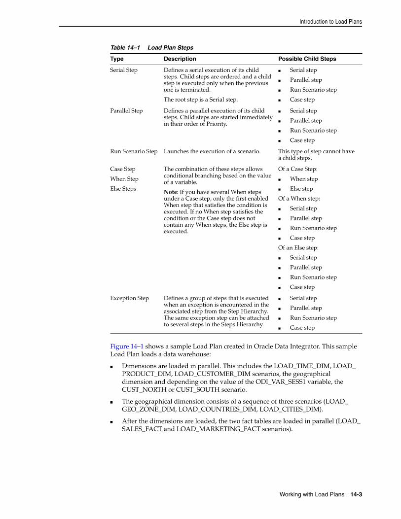
Introduction to Load Plans
Working with Load Plans 14-3
Figure 14–1 shows a sample Load Plan created in Oracle Data Integrator. This sample Load Plan loads a data warehouse:
■ Dimensions are loaded in parallel. This includes the LOAD_TIME_DIM, LOAD_PRODUCT_DIM, LOAD_CUSTOMER_DIM scenarios, the geographical dimension and depending on the value of the ODI_VAR_SESS1 variable, the CUST_NORTH or CUST_SOUTH scenario.
■ The geographical dimension consists of a sequence of three scenarios (LOAD_GEO_ZONE_DIM, LOAD_COUNTRIES_DIM, LOAD_CITIES_DIM).
■ After the dimensions are loaded, the two fact tables are loaded in parallel (LOAD_SALES_FACT and LOAD_MARKETING_FACT scenarios).
Table 14–1 Load Plan Steps
Type Description Possible Child Steps
Serial Step Defines a serial execution of its child steps. Child steps are ordered and a child step is executed only when the previous one is terminated.
The root step is a Serial step.
■ Serial step
■ Parallel step
■ Run Scenario step
■ Case step
Parallel Step Defines a parallel execution of its child steps. Child steps are started immediately in their order of Priority.
■ Serial step
■ Parallel step
■ Run Scenario step
■ Case step
Run Scenario Step Launches the execution of a scenario. This type of step cannot have a child steps.
Case Step
When Step
Else Steps
The combination of these steps allows conditional branching based on the value of a variable.
Note: If you have several When steps under a Case step, only the first enabled When step that satisfies the condition is executed. If no When step satisfies the condition or the Case step does not contain any When steps, the Else step is executed.
Of a Case Step:
■ When step
■ Else step
Of a When step:
■ Serial step
■ Parallel step
■ Run Scenario step
■ Case step
Of an Else step:
■ Serial step
■ Parallel step
■ Run Scenario step
■ Case step
Exception Step Defines a group of steps that is executed when an exception is encountered in the associated step from the Step Hierarchy. The same exception step can be attached to several steps in the Steps Hierarchy.
■ Serial step
■ Parallel step
■ Run Scenario step
■ Case step
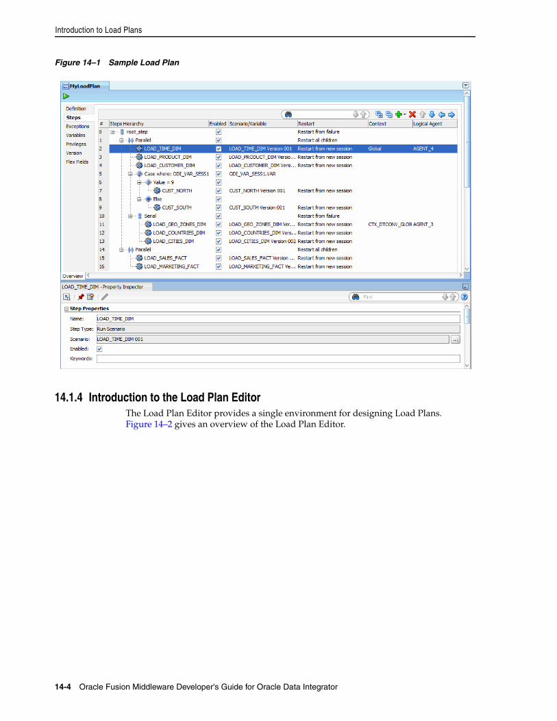
Introduction to Load Plans
14-4 Oracle Fusion Middleware Developer's Guide for Oracle Data Integrator
Figure 14–1 Sample Load Plan
14.1.4 Introduction to the Load Plan EditorThe Load Plan Editor provides a single environment for designing Load Plans. Figure 14–2 gives an overview of the Load Plan Editor.
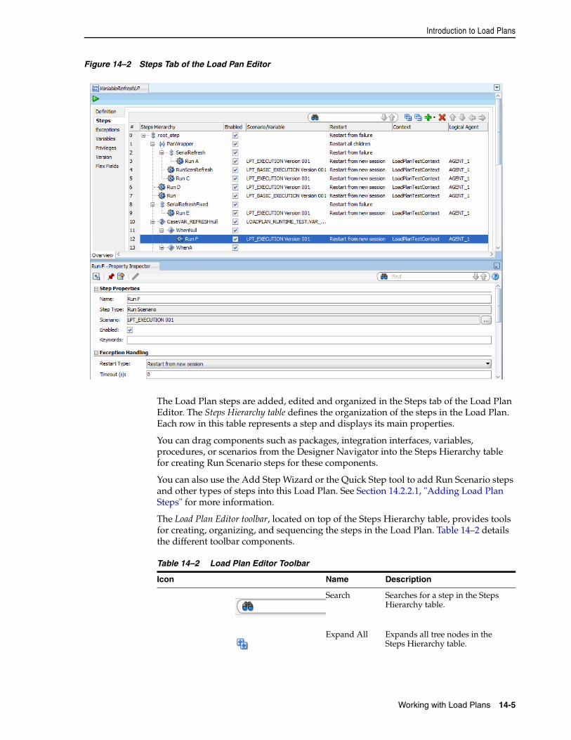
Introduction to Load Plans
Working with Load Plans 14-5
Figure 14–2 Steps Tab of the Load Pan Editor
The Load Plan steps are added, edited and organized in the Steps tab of the Load Plan Editor. The Steps Hierarchy table defines the organization of the steps in the Load Plan. Each row in this table represents a step and displays its main properties.
You can drag components such as packages, integration interfaces, variables, procedures, or scenarios from the Designer Navigator into the Steps Hierarchy table for creating Run Scenario steps for these components.
You can also use the Add Step Wizard or the Quick Step tool to add Run Scenario steps and other types of steps into this Load Plan. See Section 14.2.2.1, "Adding Load Plan Steps" for more information.
The Load Plan Editor toolbar, located on top of the Steps Hierarchy table, provides tools for creating, organizing, and sequencing the steps in the Load Plan. Table 14–2 details the different toolbar components.
Table 14–2 Load Plan Editor Toolbar
Icon Name Description
Search Searches for a step in the Steps Hierarchy table.
Expand All Expands all tree nodes in the Steps Hierarchy table.
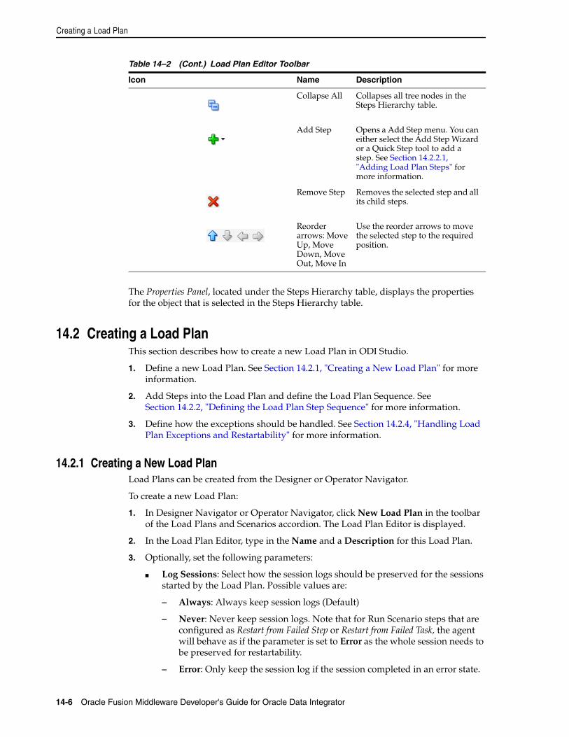
Creating a Load Plan
14-6 Oracle Fusion Middleware Developer's Guide for Oracle Data Integrator
The Properties Panel, located under the Steps Hierarchy table, displays the properties for the object that is selected in the Steps Hierarchy table.
14.2 Creating a Load PlanThis section describes how to create a new Load Plan in ODI Studio.
1. Define a new Load Plan. See Section 14.2.1, "Creating a New Load Plan" for more information.
2. Add Steps into the Load Plan and define the Load Plan Sequence. See Section 14.2.2, "Defining the Load Plan Step Sequence" for more information.
3. Define how the exceptions should be handled. See Section 14.2.4, "Handling Load Plan Exceptions and Restartability" for more information.
14.2.1 Creating a New Load PlanLoad Plans can be created from the Designer or Operator Navigator.
To create a new Load Plan:
1. In Designer Navigator or Operator Navigator, click New Load Plan in the toolbar of the Load Plans and Scenarios accordion. The Load Plan Editor is displayed.
2. In the Load Plan Editor, type in the Name and a Description for this Load Plan.
3. Optionally, set the following parameters:
■ Log Sessions: Select how the session logs should be preserved for the sessions started by the Load Plan. Possible values are:
– Always: Always keep session logs (Default)
– Never: Never keep session logs. Note that for Run Scenario steps that are configured as Restart from Failed Step or Restart from Failed Task, the agent will behave as if the parameter is set to Error as the whole session needs to be preserved for restartability.
– Error: Only keep the session log if the session completed in an error state.
Collapse All Collapses all tree nodes in the Steps Hierarchy table.
Add Step Opens a Add Step menu. You can either select the Add Step Wizard or a Quick Step tool to add a step. See Section 14.2.2.1, "Adding Load Plan Steps" for more information.
Remove Step Removes the selected step and all its child steps.
Reorder arrows: Move Up, Move Down, Move Out, Move In
Use the reorder arrows to move the selected step to the required position.
Table 14–2 (Cont.) Load Plan Editor Toolbar
Icon Name Description
Creating a Load Plan
Working with Load Plans 14-7
■ Log Session Step: Select how the logs should be maintained for the session steps of each of the session started by the Load Plan. Note that this applies only when the session log is preserved. Possible values are:
– By Scenario Settings: Session step logs are preserved depending on the scenario settings. Note that for scenarios created from packages, you can specify whether to preserve or not the steps in the advanced step property called Log Steps in the Journal. Other scenarios preserve all the steps (Default).
– Never: Never keep session step logs. Note that for Run Scenario steps that are configured as Restart from Failed Step or Restart from Failed Task, the agent will behave as if the parameter is set to Error as the whole session needs to be preserved for restartability.
– Errors: Only keep session step log if the step is in an error state.
■ Session Task Log Level: Select the log level for the sessions. This value corresponds to the Log Level value when starting unitary scenarios. Default is 5. Note that when Run Scenario steps are configured as Restart from Failed Step or Restart From Failed Task, this parameter is ignored as the whole session needs to be preserved for restartability.
■ Keywords: Enter a comma separated list of keywords that will be set on the sessions started from this load plan. These keywords improve the organization of ODI logs by session folders and automatic classification. Note that you can overwrite these keywords at the level of the child steps. See Section 21.3.3, "Managing the Log" for more information.
4. Go to the Steps tab and add steps as described in Section 14.2.2, "Defining the Load Plan Step Sequence".
5. If your Load Plan requires conditional branching, or if your scenarios use variables, go to the Variables tab and declare variables as described in Section 14.2.3.1, "Declaring Load Plan Variables".
6. To add exception steps that are used in the event of a load plan step failing, go to the Exceptions tab and define exception steps as described in Section 14.2.4.1, "Defining Exceptions Flows".
7. From the File menu, click Save.
The Load Plan appears in the Load Plans and Scenarios accordion. You can organize your Load Plans by grouping related Load Plans and Scenarios into a Load Plan and Scenarios folder.
14.2.2 Defining the Load Plan Step SequenceLoad Plans are an organized hierarchy of child steps. This hierarchy allows conditional processing of steps in parallel or in series.
The execution flow can be configured at two stages:
■ At Design-time, when defining the Steps Hierarchy:
– When you add a step to a Load Plan, you select the step type. The step type defines the possible child steps and how these child steps are executed: in parallel, in series, or conditionally based on the value of a variable (Case step). See Table 14–1 for more information on step types.
– When you add a step to a Load Plan, you also decide where to insert the step. You can add a child step, a sibling step after the selected step, or a sibling step
Creating a Load Plan
14-8 Oracle Fusion Middleware Developer's Guide for Oracle Data Integrator
before the selected step. See Section 14.2.2.1, "Adding Load Plan Steps" for more information.
– You can also reorganize the order of the Load Plan steps by dragging the step to the wanted position or by using the arrows in the Step table toolbar. See Table 14–2 for more information.
■ At design-time and run-time by enabling or disabling a step. In the Steps hierarchy table, you can enable or disable a step. Note that disabling a step also disables all its child steps. Disabled steps and all their child steps are not executed when you run the load plan.
This section contains the following topics:
■ Adding Load Plan Steps
■ Editing Load Plan Steps
■ Deleting a Step
■ Duplicating a Step
14.2.2.1 Adding Load Plan StepsA Load Plan step can be added either by using the Add Step Wizard or by selecting the Quick Step tool for a specific step type. See Table 14–1 for more information on the different types of Load Plan steps. To create Run Scenario steps, you can also drag components such as packages, integration interfaces, variables, procedures, or scenarios from the Designer Navigator into the Steps Hierarchy table. Oracle Data Integrator automatically creates a Run Scenario step for the inserted component.
When a Load Plan step is added, it is inserted into the Steps Hierarchy with the minimum required settings. See Section 14.2.2.2, "Editing Load Plan Steps" for more information on how to configure Load Plan steps.
Adding a Load Plan Step with the Add Step WizardTo insert Load Plan step with the Add Step Wizard:
1. Open the Load Plan Editor and go to the Steps tab.
2. Select a step in the Steps Hierarchy table.
3. In the Load Plan Editor toolbar, select Add Step > Add Step Wizard.
4. In the Add Step Wizard, select:
■ Step Type. Possible step types are: Serial, Parallel, Run Scenario, Case, When, and Else. See Table 14–1 for more information on the different step types.
■ Step Location. This parameter defines where the step is added.
– Add a child step to selection: The step is added under the selected step.
– Add a sibling step after selection: The step is added on the same level after the selected step.
– Add a sibling step before selection: The step is added on the same level before the selected step.
5. Click Next.
Note: Only values that are valid for the current selection are displayed for the Step Type and Step Location.
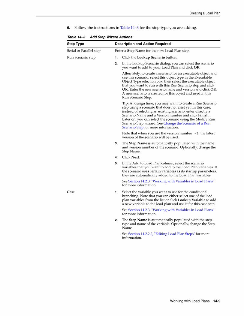
Creating a Load Plan
Working with Load Plans 14-9
6. Follow the instructions in Table 14–3 for the step type you are adding.
Table 14–3 Add Step Wizard Actions
Step Type Description and Action Required
Serial or Parallel step Enter a Step Name for the new Load Plan step.
Run Scenario step 1. Click the Lookup Scenario button.
2. In the Lookup Scenario dialog, you can select the scenario you want to add to your Load Plan and click OK.
Alternately, to create a scenario for an executable object and use this scenario, select this object type in the Executable Object Type selection box, then select the executable object that you want to run with this Run Scenario step and click OK. Enter the new scenario name and version and click OK. A new scenario is created for this object and used in this Run Scenario Step.
Tip: At design time, you may want to create a Run Scenario step using a scenario that does not exist yet. In this case, instead of selecting an existing scenario, enter directly a Scenario Name and a Version number and click Finish. Later on, you can select the scenario using the Modify Run Scenario Step wizard. See Change the Scenario of a Run Scenario Step for more information.
Note that when you use the version number -1, the latest version of the scenario will be used.
3. The Step Name is automatically populated with the name and version number of the scenario. Optionally, change the Step Name.
4. Click Next.
5. In the Add to Load Plan column, select the scenario variables that you want to add to the Load Plan variables. If the scenario uses certain variables as its startup parameters, they are automatically added to the Load Plan variables.
See Section 14.2.3, "Working with Variables in Load Plans" for more information.
Case 1. Select the variable you want to use for the conditional branching. Note that you can either select one of the load plan variables from the list or click Lookup Variable to add a new variable to the load plan and use it for this case step.
See Section 14.2.3, "Working with Variables in Load Plans" for more information.
2. The Step Name is automatically populated with the step type and name of the variable. Optionally, change the Step Name.
See Section 14.2.2.2, "Editing Load Plan Steps" for more information.
Creating a Load Plan
14-10 Oracle Fusion Middleware Developer's Guide for Oracle Data Integrator
7. Click Finish.
8. The step is added in the steps hierarchy.
Adding a Load Plan Step with the Quick Step ToolTo insert Load Plan step with the Quick Step Tool:
1. Open the Load Plan editor and go to the Steps tab.
2. In the Steps Hierarchy, select the Load Plan step under which you want to create a child step.
3. In the Steps toolbar, select Add Step and the Quick Step option corresponding to the Step type you want to add. Table 14–4 lists the options of the Quick Step tool.
When 1. Select the Operator to use in the WHEN clause evaluation. Possible values are:
■ Less Than (<)
■ Less Than or Equal (<=)
■ Different (<>)
■ Equals (=)
■ Greater Than (>)
■ Greater Than or Equal (>=)
■ Is not Null
■ Is Null
2. Enter the Value to use in the WHEN clause evaluation.
3. The Step Name is automatically populated with the operator that is used. Optionally, change the Step Name.
See Section 14.2.2.2, "Editing Load Plan Steps" for more information.
Else The Step Name is automatically populated with the step type. Optionally, change the Step Name.
See Section 14.2.2.2, "Editing Load Plan Steps" for more information.
Note: You can reorganize the order of the Load Plan steps by dragging the step to the desired position or by using the reorder arrows in the Step table toolbar to move a step in the Steps Hierarchy.
Table 14–4 Quick Step Tool
Quick Step tool option Description and Action Required
Adds a serial step after the selection. Default values are used. You can modify these values in the Steps Hierarchy table or in the Property Inspector. See Section 14.2.2.2, "Editing Load Plan Steps" for more information.
Table 14–3 (Cont.) Add Step Wizard Actions
Step Type Description and Action Required
Creating a Load Plan
Working with Load Plans 14-11
14.2.2.2 Editing Load Plan StepsTo edit a Load Plan step:
1. Open the Load Plan editor and go to the Steps tab.
2. In the Steps Hierarchy table, select the Load Plan step you want modify. The Property Inspector displays the step properties.
3. Edit the Load Plan step properties according to your needs.
The following operations are common tasks when editing steps:
■ Change the Scenario of a Run Scenario Step
■ Set Advanced Options for Run Scenario Steps
■ Open the Linked Object of Run Scenario Steps
■ Change the Test Variable in Case Steps
■ Define the Exception and Restart Behavior
■ Regenerate Scenarios
■ Refresh Scenarios to Latest Version
Change the Scenario of a Run Scenario StepTo change the scenario:
1. In the Steps Hierarchy table of the Steps or Exceptions tab, select the Run Scenario step.
2. In the Step Properties section of the Properties Inspector, click Lookup Scenario. This opens the Modify Run Scenario Step wizard.
3. In the Modify Run Scenario Step wizard, click Lookup Scenario and follow the instructions in Table 14–3 corresponding to the Run Scenario step.
Adds a parallel step after the selection. Default values are used. You can modify these values in the Steps Hierarchy table or in the Property Inspector. See Section 14.2.2.2, "Editing Load Plan Steps" for more information.
Adds a run scenario step after the selection. Follow the instructions for Run Scenario steps in Table 14–3.
Adds a Case step after the selection. Follow the instructions for Case steps in Table 14–3.
Adds a When step after the selection. Follow the instructions for When steps in Table 14–3.
Adds an Else step after the selection. Follow the instructions for Else steps in Table 14–3.
Note: Only step types that are valid for the current selection are enabled in the Quick Step tool.
Table 14–4 (Cont.) Quick Step Tool
Quick Step tool option Description and Action Required
Creating a Load Plan
14-12 Oracle Fusion Middleware Developer's Guide for Oracle Data Integrator
Set Advanced Options for Run Scenario StepsYou can set the following properties for Run Scenario steps in the Property Inspector:
■ Priority: Priority for this step when the scenario needs to start in parallel. The integer value range is from 0 to 100 (100 being the highest priority). Default is 0. The priority of a Run Scenario step is evaluated among all runnable scenarios within a running Load Plan. The Run Scenario step with the highest priority is executed first.
■ Context: Context that is used for the step execution. Default context is the Load Plan context that is defined in the Start Load Plan Dialog when executing a Load Plan. Note that if you only specify the Context and no Logical Agent value, the step is started on the same physical agent that started the Load Plan, but in this specified context.
■ Logical Agent: Logical agent that is used for the step execution. By default, the logical agent, which is defined in the Start Load Plan Dialog when executing a Load Plan, is used. Note that if you set only the Logical Agent and no context, the step is started with the physical agent corresponding to the specified Logical Agent resolved in the context specified when starting the Load Plan. If no Logical Agent value is specified, the step is started on the same physical agent that started the Load Plan (whether a context is specified for the step or not).
Open the Linked Object of Run Scenario StepsRun Scenario steps can be created for packages, integration interfaces, variables, procedures, or scenarios. Once this Run Scenario step is created, you can open the Object Editor of the original object to view and edit it.
To view and edit the linked object of Run Scenario steps:
1. In the Steps Hierarchy table of the Steps or Exceptions tab, select the Run Scenario step.
2. Right-click and select Open the Linked Object.
The Object Editor of the linked object is displayed.
Change the Test Variable in Case StepsTo change the variable that is used for evaluating the tests defined in the WHEN statements:
1. In the Steps Hierarchy table of the Steps tab or Exceptions tab, select the Case step.
2. In the Step Properties section of the Properties Inspector, click Lookup Variable. This opens the Modify Case Step Dialog.
3. In the Modify Case Step Dialog, click Lookup Variable and follow the instructions in Table 14–3 corresponding to the Case step.
Define the Exception and Restart BehaviorException and Restart behavior can be set on the steps in the Steps Hierarchy table. See Section 14.2.4, "Handling Load Plan Exceptions and Restartability" for more information.
Regenerate ScenariosTo regenerate all the scenarios of a given Load Plan step, including the scenarios of its child steps:
Creating a Load Plan
Working with Load Plans 14-13
1. From the Steps Hierarchy table of the Steps tab or Exceptions tab, select the Load Plan step.
2. Right-click and select Regenerate. Note that this option is not available for scenarios with the version number -1.
3. Click OK.
Refresh Scenarios to Latest Version To modify all the scenario steps of a given Load Plan step, including the scenarios of its child steps, and set the scenario version to the latest version available for each scenario:
1. From the Steps Hierarchy table of the Steps tab or Exceptions tab, select the Load Plan step.
2. Right-click and select Refresh Scenarios to Latest Version. Note that this option is not available for scenarios with the version number -1.
3. Click OK.
14.2.2.3 Deleting a StepTo delete a step:
1. Open the Load Plan Editor and go to the Steps tab.
2. In the Steps Hierarchy table, select the step to delete.
3. In the Load Plan Editor toolbar, select Remove Step.
The step and its child steps are removed from the Steps Hierarchy table.
14.2.2.4 Duplicating a StepTo duplicate a step:
1. Open the Load Plan Editor and go to the Steps tab.
2. In the Steps Hierarchy table, right-click the step to duplicate and select Duplicate Selection.
3. A copy of this step, including its child steps, is created and added as a sibling step after the original step to the Step Hierarchy table.
You can now move and edit this step.
14.2.3 Working with Variables in Load PlansProject and Global Variables used in a Load Plan are declared as Load Plan Variables in the Load Plan editor. These variables are automatically available in all steps and their value passed to the Load Plan steps.
Caution: Regenerating a scenario cannot be undone. For important scenarios, it is better to generate a scenario with a new version number.
Note: It is not possible to undo a delete operation in the Steps Hierarchy table.
Creating a Load Plan
14-14 Oracle Fusion Middleware Developer's Guide for Oracle Data Integrator
The value of the variables are passed to the Load Plan on startup as startup parameters. At a step level, you can overwrite the variable value (by setting it or forcing a refresh) for this step and its child steps.
You can use variables in Run Scenario steps - the value of the variable are passed as startup parameters to the scenario - or in Case/When/Else steps for conditional branching.
This section contains the following topics:
■ Declaring Load Plan Variables
■ Setting Variable Values in a Step
14.2.3.1 Declaring Load Plan VariablesTo declare a Load Plan variable:
1. Open the Load Plan editor and go to the Variables tab.
2. From the Load Plan Editor toolbar, select Add Variable. The Lookup Variable dialog is displayed.
3. In the Lookup Variable dialog, select the variable to add your Load Plan.
4. The variable appears in the Variables tab of the Load Plan Editor and in the Property Inspector of each step.
14.2.3.2 Setting Variable Values in a StepVariables in a step inherit their value from the value from the parent step and ultimately from the value specified for the variables when starting the Load Plan.
For each step, except for Else and When steps, you can also overwrite the variable value, and change the value used for this step and its child steps.
To override variable values at step level:
1. Open the Load Plan editor and go to the Steps tab.
2. In the Steps Hierarchy table, select the step for which you want to overwrite the variable value.
3. In the Property Inspector, go to the Variables section. The variables that are defined for this Load Plan are listed in this Variables table. You can modify the following variable parameters:
Select Overwrite, if you want to specify a variable value for this step and all its children. Once you have chosen to overwrite the variable value, you can either:
– Set a new variable value in the Value field.
– Select Refresh to refresh this variable prior to executing the step. The Refresh option can be selected only for variables with a Select Query defined for refreshing the variable value.
Note: At startup, Load Plans do not take into account the default value of a variable, or the historized/latest value of a variable in the execution context. The value of the variable is either the one specified when starting the Load Plan, or the value set/refreshed within the Load Plan.
Creating a Load Plan
Working with Load Plans 14-15
14.2.4 Handling Load Plan Exceptions and RestartabilityLoad Plans provide two features for handling error cases in the execution flows: Exceptions and Restartability.
ExceptionsAn Exception Step contains a hierarchy of steps that is defined on the Exceptions tab of the Load Plan editor.
You can associate a given exception step to one or more steps in the Load Plan. When a step in the Load Plan errors out, the associated exception step is executed automatically.
Exceptions can be optionally raised to the parent step of the failing step. Raising an exception fails the parent step, which can consequently execute its exception step.
RestartabilityWhen a Load Plan Run is restarted after a failure, the failed Load Plan steps are restarted depending on the Restart Type parameter. For example, you can define whether a parallel step should restart all its child steps or only those that have failed.
This section contains the following topics:
■ Defining Exceptions Flows
■ Using Exception Handling
■ Defining the Restart Behavior
14.2.4.1 Defining Exceptions FlowsException steps are created and defined on the Exceptions tab of the Load Plan Editor.
This tab contains a list of Exception Steps. Each Exception Step consists in a hierarchy of Load Plan steps.
The Exceptions tab is similar to the Steps tab in the Load Plan editor. The main differences are:
■ There is no root step for the Exception Step hierarchy. Each exception step is a separate root step.
■ The Serial, Parallel, Run Scenario, and Case steps have the same properties as on the Steps tab but do not have an Exception Handling properties group. An exception step that errors out cannot raise another exception step.
An Exception step can be created either by using the Add Step Wizard or with the Quick Step tool by selecting the Add Step > Exception Step in the Load Plan Editor toolbar. By default, the Exception step is created with the Step name: Exception. You can modify this name in the Steps Hierarchy table or in the Property Inspector.
To create an Exception step with the Add Step Wizard:
1. Open the Load Plan Editor and go to the Exceptions tab.
2. In the Load Plan Editor toolbar, select Add Step > Add Step Wizard.
3. In the Add Step Wizard, select Exception from the Step Type list.
Note: Only values that are valid for the current selection are displayed for the Step Type.
Creating a Load Plan
14-16 Oracle Fusion Middleware Developer's Guide for Oracle Data Integrator
4. Click Next.
5. In the Step Name field, enter a name for the Exception step.
6. Click Finish.
7. The Exception step is added in the steps hierarchy.
You can now define the exception flow by adding new steps and organizing the hierarchy under this exception step.
14.2.4.2 Using Exception HandlingDefining exception handling for a Load Plan step consists of associating an Exception Step to this Load Plan step and defining the exception behavior. Exceptions steps can be set for each step except for When and Else steps.
To define exception handling for a Load Plan step:
1. Open the Load Plan Editor and go to the Steps tab.
2. In the Steps Hierarchy table, select the step for which you want to define an exception behavior. The Property Inspector displays the Step properties.
3. In the Exception Handling section of the Property Inspector, set the parameters as follows:
■ Timeout (s): Enter the maximum time (in seconds) that this step takes before it is aborted by the Load Plan. When a time-out is reached, the step is marked in error and the Exception step (if defined) is executed. In this case, the exception step never times out. If needed, a timeout can be set on a parent step to safe guard such a potential long running situation.
If the step fails before the timeout and an exception step is executed, then the execution time of the step plus the execution time of the exception step should not exceed the timeout, otherwise the exception step will fail when the timeout is reached.
Note that the default value of zero (0) indicates an infinite timeout.
■ Exception Step: From the list, select the Exception step to execute if this step fails. Note that only Exception steps that have been created and defined on the Exceptions tab of the Load Plan Editor appear in this list. See Section 14.2.4.1, "Defining Exceptions Flows" for more information on how to create an Exception step.
■ Exception Behavior: Defines how this step behaves in case an exception is encountered. Select one of the following:
– Run Exception and Raise: Runs the Exception Step (if any) and raises the exception to the parent step.
– Run Exception and Ignore: Runs the Exception Step (if any) and ignores the exception. The parent step is notified of a successful run. Note that if an exception is caused by the exception step itself, the parent step is notified of the failure.
For Parallel steps only, the following parameters may be set:
Max Error Child Count: Displays the maximum number of child steps in error that is accepted before this step is to be considered in error. When the number of failed child steps exceeds this value, the parallel step is considered failed. The currently running child steps are continued or stopped depending on the Restart Type parameter for this parallel step:
Running Load Plans
Working with Load Plans 14-17
– If the Restart type is Restart from failed children, the Load Plan waits for all child sessions (these are the currently running sessions and the ones waiting to be executed) to run and complete before it raises the error to the parent step.
– If the Restart Type is Restart all children, the Load Plan kills all running child sessions and does not start any new ones before it raises the error to the parent.
14.2.4.3 Defining the Restart BehaviorThe Restart Type option defines how a step in error restarts when the Load Plan is restarted. You can define the Restart Type parameter in the Exception Handling section of the Properties Inspector.
Depending on the step type, the Restart Type parameter can take the values listed in Table 14–5.
14.3 Running Load PlansYou can run a Load Plan from Designer Navigator or Operator Navigator in ODI Studio.
To run a Load Plan in Designer Navigator or Operator Navigator:
1. In the Load Plans and Scenarios accordion, select the Load Plan you want to execute.
2. Right-click and select Execute.
3. In the Start Load Plan dialog, select the execution parameters:
Table 14–5 Restart Type Values
Step Type Values and Description
Serial ■ Restart all children: When the Load Plan is restarted and if this step is in error, the sequence of steps restarts from the first one.
■ Restart from failure: When the Load Plan is restarted and if this step is in error, the sequence of child steps starts from the one that has failed.
Parallel ■ Restart all children: When the Load Plan is restarted and if this step is in error, all the child steps are restarted regardless of their status. This is the default value.
■ Restart from failed children: When the Load Plan is restarted and if this step is in error, only the failed child steps are restarted in parallel.
Run Scenario ■ Restart from new session: When restarting the Load Plan and this Run Scenario step is in error, start the scenario and create a new session. This is the default value.
■ Restart from failed step: When restarting the Load Plan and this Run Scenario step is in error, restart the session from the step in error. All the tasks under this step are restarted.
■ Restart from failed task: When restarting the Load Plan and this Run Scenario step is in error, restart the session from the task in error.
The same limitation as those described in Section 20.4, "Restarting a Session" apply to the sessions restarted from a failed step or failed task.
Using Load Plans in Production
14-18 Oracle Fusion Middleware Developer's Guide for Oracle Data Integrator
■ Select the Context into which the Load Plan will be executed.
■ Select the Logical Agent that will run the Load Plan.
■ In the Variables table, enter the Startup values for the variables used in this Load Plan.
4. Click OK.
5. The Load Plan Started dialog is displayed.
6. Click OK.
The Load Plan execution starts: a Load Plan instance is created along with the first Load Plan run. You can review the Load Plan execution in the Operator Navigator. See Chapter 21, "Monitoring Integration Processes" for more information. See also Chapter 20, "Running Integration Processes" for more information on the other run-time operations on Load Plans.
14.4 Using Load Plans in ProductionUsing Load Plans in production involves the following tasks:
■ Starting, monitoring, stopping and restarting Load Plans. See Section 14.4.1, "Running Load Plans in Production" for information.
■ Scheduling Load Plans. See Section 14.4.2, "Scheduling Load Plans" for more information.
■ Moving Load Plans across environments. See Section 14.4.3, "Exporting, Importing and Versioning Load Plans"
14.4.1 Running Load Plans in ProductionIn Production, the following tasks can be performed to execute Load Plans interactively:
■ Executing a Load Plan
■ Restarting a Load Plan Run
■ Stopping a Load Plan Run
14.4.2 Scheduling Load PlansYou can schedule the executions of your scenarios and Load Plans using the Oracle Data Integrator built-in scheduler or an external scheduler. See Section 20.9, "Scheduling Scenarios and Load Plans" for more information.
14.4.3 Exporting, Importing and Versioning Load PlansA Load Plan can be exported and then imported into a development or execution repository. This operation is used to deploy Load Plans in a different repository, possibly in a different environment or site.
The export (and import) procedure allows you to transfer Oracle Data Integrator objects from one repository to another.
14.4.3.1 Exporting Load PlansIt is possible to export a single Load Plan or several Load Plans at once.
Using Load Plans in Production
Working with Load Plans 14-19
Exporting one single Load Plan follows the standard procedure described in Section 19.2.1, "Exporting one ODI Object".
For more information on exporting several Load Plans at once, see Section 19.2.2, "Export Multiple ODI Objects".
Note that when you export a Load Plan and you select Export child objects, all its child steps, schedules, and variables are also exported.
14.4.3.2 Importing Load PlansImporting a Load Plan in a development repository is performed via Designer or Operator Navigator. With an execution repository, only Operator Navigator is available for this purpose.
The Load Plan import uses the standard object import method. See Section 19.2.3, "Importing Objects" for more information.
14.4.3.3 Versioning Load PlansLoad Plans can also be deployed and promoted to production using versions and solutions. See Chapter 18, "Working with Version Management" for more information.
Note: The export of a Load Plan does not include the scenarios referenced by the Load Plan. Scenarios used in a Load Plan need to be exported separately. How to export scenarios is described in Section 13.5, "Exporting Scenarios".
Note: The export of a Load Plan does not include the scenarios referenced by the Load Plan. Scenarios used in a Load Plan need to be imported separately.

Using Load Plans in Production
14-20 Oracle Fusion Middleware Developer's Guide for Oracle Data Integrator
15
Working with Web Services in Oracle Data Integrator 15-1
15Working with Web Services in Oracle DataIntegrator
This chapter describes how to work with web services in Oracle Data Integrator.
This chapter includes the following sections:
■ Section 15.1, "Introduction to Web Services in Oracle Data Integrator"
■ Section 15.2, "Data Services"
■ Section 15.3, "Oracle Data Integrator Run-Time Services"
■ Section 15.4, "Invoking Third-Party Web Services"
15.1 Introduction to Web Services in Oracle Data IntegratorOracle Data Integrator provides the following entry points into a service-oriented architecture (SOA):
■ Data Services
■ Oracle Data Integrator Run-Time Services
■ Invoking Third-Party Web Services
Figure 15–1 gives an overview of how the different types of Web services can interact.
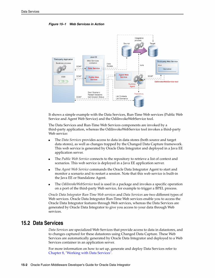
Data Services
15-2 Oracle Fusion Middleware Developer's Guide for Oracle Data Integrator
Figure 15–1 Web Services in Action
It shows a simple example with the Data Services, Run-Time Web services (Public Web Service and Agent Web Service) and the OdiInvokeWebService tool.
The Data Services and Run-Time Web Services components are invoked by a third-party application, whereas the OdiInvokeWebService tool invokes a third-party Web service:
■ The Data Services provides access to data in data stores (both source and target data stores), as well as changes trapped by the Changed Data Capture framework. This web service is generated by Oracle Data Integrator and deployed in a Java EE application server.
■ The Public Web Service connects to the repository to retrieve a list of context and scenarios. This web service is deployed in a Java EE application server.
■ The Agent Web Service commands the Oracle Data Integrator Agent to start and monitor a scenario and to restart a session. Note that this web service is built-in the Java EE or Standalone Agent.
■ The OdiInvokeWebService tool is used in a package and invokes a specific operation on a port of the third-party Web service, for example to trigger a BPEL process.
Oracle Data Integrator Run-Time Web services and Data Services are two different types of Web services. Oracle Data Integrator Run-Time Web services enable you to access the Oracle Data Integrator features through Web services, whereas the Data Services are generated by Oracle Data Integrator to give you access to your data through Web services.
15.2 Data ServicesData Services are specialized Web Services that provide access to data in datastores, and to changes captured for these datastores using Changed Data Capture. These Web Services are automatically generated by Oracle Data Integrator and deployed to a Web Services container in an application server.
For more information on how to set up, generate and deploy Data Services refer to Chapter 8, "Working with Data Services".
Invoking Third-Party Web Services
Working with Web Services in Oracle Data Integrator 15-3
15.3 Oracle Data Integrator Run-Time ServicesOracle Data Integrator Run-Time Services are web services that enable users to leverage Oracle Data Integrator features in a service-oriented architecture (SOA). These web services are invoked by a third-party application manage start scenarios developed with Oracle Data Integrator.
How to perform the different ODI execution tasks with the ODI Run-Time Services such as executing a scenario, restarting a session, listing execution contexts and scenarios is detailed in Section 20.11, "Managing Executions Using Web Services". Section 20.11 also provides examples of SOAP requests and responses.
15.4 Invoking Third-Party Web ServicesThis section describes how to invoke third-party web services in Oracle Data Integrator.
This section includes the following topics:
■ Section 15.4.1, "Introduction to Web Service Invocation"
■ Section 15.4.2, "Using the OdiInvokeWebService Tool"
■ Section 15.4.3, "Web Service Invocation in Integration Flows"
15.4.1 Introduction to Web Service InvocationWeb Services can be invoked:
■ In Oracle Data Integrator packages or procedures using the OdiInvokeWebService tool: This tool allows you to invoke any third party web service, and save the response in a XML file that can be processed with Oracle Data Integrator.
■ For testing Data Services: The easiest way to test whether your generated data services are running correctly is to use the graphical interface of the OdiInvokeWebService tool. See Section 15.4.2, "Using the OdiInvokeWebService Tool" for more information.
15.4.2 Using the OdiInvokeWebService ToolThe OdiInvokeWebService tool invokes a web service using the HTTP or HTTPS protocol and is able to write the returned response to an XML file, which can be an XML payload or a full-formed SOAP message including a SOAP header and body. The OdiInvokeWebService tool invokes a specific operation on a port of a web service whose description file (WSDL) URL is provided. If this operation requires a SOAP request, it is provided either in a request file or in the tool command. The response of the web service request is written to an XML file that can be used in Oracle Data Integrator.
How to create a web service request is detailed in Section 15.4.3, "Web Service Invocation in Integration Flows".
Note: If the web service operation is one-way and does not return any response, no response file is generated.
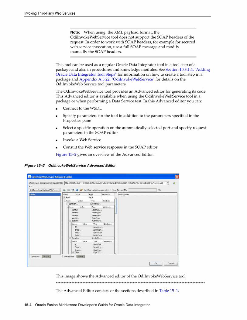
Invoking Third-Party Web Services
15-4 Oracle Fusion Middleware Developer's Guide for Oracle Data Integrator
This tool can be used as a regular Oracle Data Integrator tool in a tool step of a package and also in procedures and knowledge modules. See Section 10.3.1.4, "Adding Oracle Data Integrator Tool Steps" for information on how to create a tool step in a package and Appendix A.5.22, "OdiInvokeWebService" for details on the OdiInvokeWeb Service tool parameters.
The OdiInvokeWebService tool provides an Advanced editor for generating its code. This Advanced editor is available when using the OdiInvokeWebService tool in a package or when performing a Data Service test. In this Advanced editor you can:
■ Connect to the WSDL
■ Specify parameters for the tool in addition to the parameters specified in the Properties pane
■ Select a specific operation on the automatically selected port and specify request parameters in the SOAP editor
■ Invoke a Web Service
■ Consult the Web service response in the SOAP editor
Figure 15–2 gives an overview of the Advanced Editor.
Figure 15–2 OdiInvokeWebService Advanced Editor
This image shows the Advanced editor of the OdiInvokeWebService tool.
***********************************************************************************************
The Advanced Editor consists of the sections described in Table 15–1.
Note: When using the XML payload format, the OdiInvokeWebService tool does not support the SOAP headers of the request. In order to work with SOAP headers, for example for secured web service invocation, use a full SOAP message and modify manually the SOAP headers.
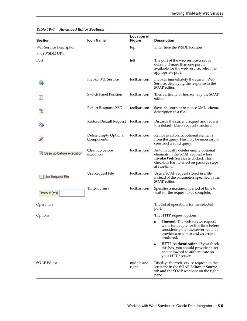
Invoking Third-Party Web Services
Working with Web Services in Oracle Data Integrator 15-5
Table 15–1 Advanced Editor Sections
Section Icon NameLocation in Figure Description
Web Service Description
File (WSDL) URL
top Enter here the WSDL location
Port left The port of the web service is set by default. If more than one port is available for the web service, select the appropriate port.
Invoke Web Service toolbar icon Invokes immediately the current Web Service, displaying the response in the SOAP editor.
Switch Panel Position toolbar icon Tiles vertically or horizontally the SOAP editor.
Export Response XSD toolbar icon Saves the current response XML schema description to a file.
Restore Default Request toolbar icon Discards the current request and reverts to a default, blank request structure.
Delete Empty Optional Components
toolbar icon Removes all blank optional elements from the query. This may be necessary to construct a valid query.
Clean up before execution
toolbar icon Automatically deletes empty optional elements in the SOAP request when Invoke Web Service is clicked. This checkbox has no effect on package steps at run-time.
Use Request File toolbar icon Uses a SOAP request stored in a file instead of the parameters specified in the SOAP editor.
Timeout (ms) toolbar icon Specifies a maximum period of time to wait for the request to be complete.
Operation The list of operations for the selected port.
Options The HTTP request options:
■ Timeout: The web service request waits for a reply for this time before considering that the server will not provide a response and an error is produced.
■ HTTP Authentication: If you check this box, you should provide a user and password to authenticate on your HTTP server.
SOAP Editor middle and right
Displays the web service request on the left pane in the SOAP Editor or Source tab and the SOAP response on the right pane.
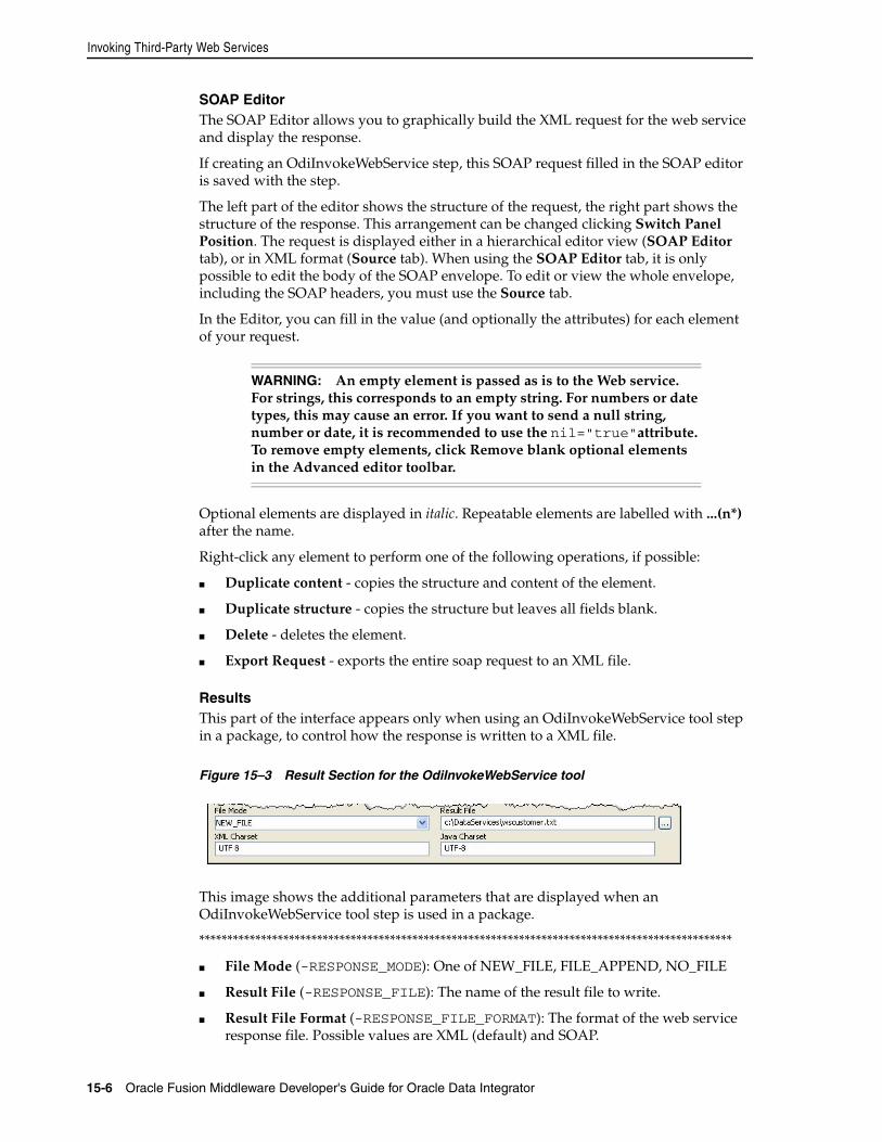
Invoking Third-Party Web Services
15-6 Oracle Fusion Middleware Developer's Guide for Oracle Data Integrator
SOAP EditorThe SOAP Editor allows you to graphically build the XML request for the web service and display the response.
If creating an OdiInvokeWebService step, this SOAP request filled in the SOAP editor is saved with the step.
The left part of the editor shows the structure of the request, the right part shows the structure of the response. This arrangement can be changed clicking Switch Panel Position. The request is displayed either in a hierarchical editor view (SOAP Editor tab), or in XML format (Source tab). When using the SOAP Editor tab, it is only possible to edit the body of the SOAP envelope. To edit or view the whole envelope, including the SOAP headers, you must use the Source tab.
In the Editor, you can fill in the value (and optionally the attributes) for each element of your request.
Optional elements are displayed in italic. Repeatable elements are labelled with ...(n*) after the name.
Right-click any element to perform one of the following operations, if possible:
■ Duplicate content - copies the structure and content of the element.
■ Duplicate structure - copies the structure but leaves all fields blank.
■ Delete - deletes the element.
■ Export Request - exports the entire soap request to an XML file.
ResultsThis part of the interface appears only when using an OdiInvokeWebService tool step in a package, to control how the response is written to a XML file.
Figure 15–3 Result Section for the OdiInvokeWebService tool
This image shows the additional parameters that are displayed when an OdiInvokeWebService tool step is used in a package.
***********************************************************************************************
■ File Mode (-RESPONSE_MODE): One of NEW_FILE, FILE_APPEND, NO_FILE
■ Result File (-RESPONSE_FILE): The name of the result file to write.
■ Result File Format (-RESPONSE_FILE_FORMAT): The format of the web service response file. Possible values are XML (default) and SOAP.
WARNING: An empty element is passed as is to the Web service. For strings, this corresponds to an empty string. For numbers or date types, this may cause an error. If you want to send a null string, number or date, it is recommended to use the nil="true"attribute. To remove empty elements, click Remove blank optional elements in the Advanced editor toolbar.
Invoking Third-Party Web Services
Working with Web Services in Oracle Data Integrator 15-7
■ XML Charset (-RESPONSE_XML_ENCODING): The name of the character encoding to write into the XML file.
■ Java Charset (-RESPONSE_FILE_CHARSET): The name of the character encoding used when writing the file.
Refer to Section A.5.22, "OdiInvokeWebService" for more information on these parameters.
15.4.3 Web Service Invocation in Integration Flows
Calling a Web Service using the OdiInvokeWebService toolTo call a Web Service:
1. Create an OdiInvokeWebService tool step in a package, or right-click a datastore and select Test Web Service in the contextual menu.
2. Fill in the location of the WSDL. You can use either:
■ A URL for a WSDL that has been deployed to a server (for example: http://host:8080/services/WSCustomer?wsdl)
■ A local file location (for example: c:/DataServices/WSCustomer.wsdl )
3. Choose a Port, if more than one is available.
4. Choose an Operation from the list on the left.
5. In the SOAP Editor, enter the web service payload. The OdiInvokeWebService tool supports two web service request formats: the XML body of the SOAP request only or the full-formed SOAP envelope, including the SOAP header and body.
6. (Optional) Click Remove blank optional elements to delete optional request parameters which have not been specified. Some Web Services treat blank elements as invalid.
7. Click Invoke Web Service to immediately invoke the Web Service. The response is shown in right pane of the SOAP Editor.
8. If you are creating an OdiInvokeWebService tool step, define the response file parameters.
Note: The result file parameters are only taken into account at run-time. No result file is generated when clicking Invoke Web Service.
Note: Input format (request) and output format (response) are independant. Oracle Data Integrator recognizes the input message format automatically and writes the response according to the RESPONSE_FILE_FORMAT (default is XML).
However, in the Advanced editor the request file format determines the response file format. If you test the invocation using a XML payload message, the response will be XML payload. If you test using a full-formed SOAP message, the response will be a full-formed SOAP message.
How to generate a web service request file with Oracle Data Integrator is covered in "Generating the Request File".
Invoking Third-Party Web Services
15-8 Oracle Fusion Middleware Developer's Guide for Oracle Data Integrator
9. From the File menu, select Save.
Processing the Response FileWhen using the OdiInvokeWebService tool to call a web service, the response is written to an XML file.
Processing this XML file can be done with Oracle Data Integrator, using the following guidelines:
1. Invoke the web service once and use the Export Response XSD option to export the XML schema.
2. Create an XML model for the response file, based on this XML schema file and reverse-engineer the XSD to have your model structure.
3. You can now process the information from your responses using regular Oracle Data Integrator interfaces sourcing for the XML technology.
Refer to the Connectivity and Modules Guide for Oracle Data Integrator for more information on XML file processing.
Oracle Data Integrator provides the OdiXMLConcat and OdiXMLSplit tools for processing the web service response. Refer to the XML section of the Appendix A.4, "ODI Tools per Category" for details on how to use these tools.
Generating the Request FileThere are several ways to create a request file:
■ Create the request directly in the SOAP Editor on the Advanced tab of the OdiInvokeWebService tool. The possible format is XML.
■ Use the XML driver, similarly to what is performed for processing the response file. If generating a request file using the XML driver, the request is not a full SOAP but a simplified XML format. Use the SOAP editor for generating a template request.
■ Use an external request file that has been previously generated with ODI. The possible formats are XML and SOAP.
■ Create a SOAP request. To generate a SOAP request, you have to use a third-party tool such as, for example, the HTTP Analyzer provided by JDeveloper. See "Using the HTTP Analyzer" in the Oracle SOA Suite Developer's Guide for more information.
To call a web service with a SOAP request, perform the standard procedure as described in Calling a Web Service using the OdiInvokeWebService tool and perform the following steps for creating the web service request in SOAP format:
1. Create the SOAP request in the third-party tool.
2. Copy the SOAP request and paste the entire SOAP message into the Source tab of the SOAP Editor in ODI Studio.
3. Optionally, edit the request.
Note: Each XML file is defined as a model in Oracle Data Integrator. When using XML file processing for the request or response file, model will be created for each request or response file. It is recommended to use model folders to arrange them. See Section 17.2, "Organizing Models with Folders" for more information.

Invoking Third-Party Web Services
Working with Web Services in Oracle Data Integrator 15-9
Note that the web service response will be in SOAP format.
Using the Binding Mechanism for RequestsIt is possible to use the Binding mechanism when using a web service call in a Procedure. With this method, it is possible to call a web service for each row returned by a query, parameterizing the request based on the row’s values. Refer to "Binding Source and Target Data" for more information.

Invoking Third-Party Web Services
15-10 Oracle Fusion Middleware Developer's Guide for Oracle Data Integrator
16
Working with Oracle Data Quality Products 16-1
16Working with Oracle Data Quality Products
This chapter describes how to work with Data Quality Products in Oracle Data Integrator.
This chapter includes the following sections:
■ Section 16.1, "Introduction to Oracle Data Quality Products"
■ Section 16.2, "The Data Quality Process"
16.1 Introduction to Oracle Data Quality ProductsOracle Data Profiling and Oracle Data Quality for Data Integrator (also referred to as Oracle Data Quality Products) extend the inline Data Quality features of Oracle Data Integrator to provide more advanced data governance capabilities.
A complete Data Quality system includes data profiling, integrity and quality:
■ Profiling makes possible data investigation and quality assessment. It allows business users to get a clear picture of their data quality challenges, to monitor and track the quality of their data over time. Profiling is handled by Oracle Data Profiling. It allows business users to assess the quality of their data through metrics, to discover or infer rules based on this data, and finally to monitor over time the evolution of the data quality.
■ Integrity control is essential in ensuring the overall consistency of the data in your information system's applications. Application data is not always valid for the constraints and declarative rules imposed by the information system. You may, for instance, find orders with no customer, or order lines with no product, and so forth. Oracle Data Integrator provides built-in working environment to detect these constraint violation and store them for recycling or reporting purposes. Static and Flow checks in Oracle Data Integrator are integrity checks.
■ Quality includes integrity and extends to more complex quality processing. A rule-based engine apply data quality standards as part of an integration process to cleanse, standardize, enrich, match and de-duplicate any type of data, including names and addresses. Oracle Data Quality for Data Integrator places data quality as well as name and address cleansing at the heart of the enterprise integration strategy.
16.2 The Data Quality ProcessThe data quality process described in this section uses Oracle Data Quality products to profile and cleanse data extracted from systems using Oracle Data Integrator. The
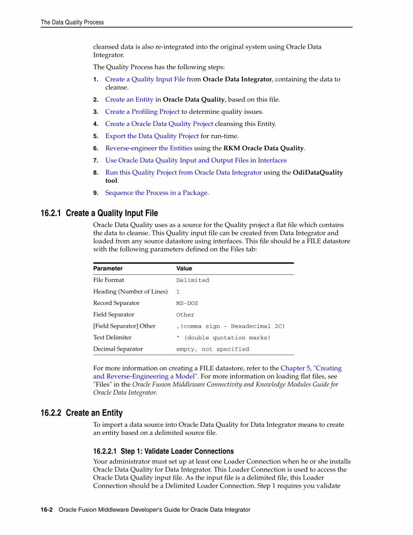
The Data Quality Process
16-2 Oracle Fusion Middleware Developer's Guide for Oracle Data Integrator
cleansed data is also re-integrated into the original system using Oracle Data Integrator.
The Quality Process has the following steps:
1. Create a Quality Input File from Oracle Data Integrator, containing the data to cleanse.
2. Create an Entity in Oracle Data Quality, based on this file.
3. Create a Profiling Project to determine quality issues.
4. Create a Oracle Data Quality Project cleansing this Entity.
5. Export the Data Quality Project for run-time.
6. Reverse-engineer the Entities using the RKM Oracle Data Quality.
7. Use Oracle Data Quality Input and Output Files in Interfaces
8. Run this Quality Project from Oracle Data Integrator using the OdiDataQuality tool.
9. Sequence the Process in a Package.
16.2.1 Create a Quality Input FileOracle Data Quality uses as a source for the Quality project a flat file which contains the data to cleanse. This Quality input file can be created from Data Integrator and loaded from any source datastore using interfaces. This file should be a FILE datastore with the following parameters defined on the Files tab:
For more information on creating a FILE datastore, refer to the Chapter 5, "Creating and Reverse-Engineering a Model". For more information on loading flat files, see "Files" in the Oracle Fusion Middleware Connectivity and Knowledge Modules Guide for Oracle Data Integrator.
16.2.2 Create an EntityTo import a data source into Oracle Data Quality for Data Integrator means to create an entity based on a delimited source file.
16.2.2.1 Step 1: Validate Loader ConnectionsYour administrator must set up at least one Loader Connection when he or she installs Oracle Data Quality for Data Integrator. This Loader Connection is used to access the Oracle Data Quality input file. As the input file is a delimited file, this Loader Connection should be a Delimited Loader Connection. Step 1 requires you validate
Parameter Value
File Format Delimited
Heading (Number of Lines) 1
Record Separator MS-DOS
Field Separator Other
[Field Separator] Other ,(comma sign - Hexadecimal 2C)
Text Delimiter " (double quotation marks)
Decimal Separator empty, not specified
The Data Quality Process
Working with Oracle Data Quality Products 16-3
this Delimited Loader Connection set up. Also verify that all the data and schema files you need are copied to the directory defined by the Loader Connection.
If you do not have access to the Metabase Manager, ask your Metabase administrator to verify the Loader Connection for you.
If you are a Metabase User and have access to the Metabase Manager, follow this procedure:
To validate a Loader Connection
1. Open the Metabase Manager (Start > All Programs > Oracle > Oracle Data Profiling and Quality > Metabase Manager).
2. Verify you are in Admin Mode.
3. Expand the Control Admin node.
4. Double-click Loader Connections.
5. On the right, the Loader Connections list view displays each Loader Connection, showing its name, type, data file, and parameters. Review the information to verify that the Loader Connection created by your administrator is a Delimited Loader Connection and that the data and schema directories are pointing to the correct location.
16.2.2.2 Step 2: Create Entity and Import DataUse the Create Entity wizard to create an Entity. The Wizard takes you through each step, helps you to select data to load, and provides an interface for specifying connection and schema settings. It also gives you options for customizing how the data appears in an Entity.
To import a delimited source file into Oracle Data Quality for Data Integrator:
1. Copy the flat file that you want to import into Oracle Data Quality for Data Integrator into the data directory that you specified when you defined the Loader Connection.
2. Click on the Windows Start menu and select All Programs > Oracle > Oracle Data Profiling and Quality > Oracle Data Profiling and Quality.
3. Log in the user interface with your metabase user. The Oracle Data Profiling and Quality user interface opens
4. From the Main menu, select Analysis >Create Entity…
5. The Create Entity wizard opens in the upper right pane.
6. On the Connection Page of the Create Entity wizard, select the Loader Connection given to you by the administrator that you have checked in Step 1.
7. Leave the default settings for the filter and the connection and click Next.
8. Oracle Data Quality connects to the data source using the Loader Connection you selected in Step 4. If the connection fails, contact your Metabase Administrator
9. In the Entity Selection dialog, select the data source file name you want to import in the list and click Next.
Note: If you are a Metabase User with full Metabase privileges, you can create a new Loader Connection.
The Data Quality Process
16-4 Oracle Fusion Middleware Developer's Guide for Oracle Data Integrator
10. Select the schema settings for the selected data file corresponding to the parameters of the file described in the section Section 16.2.1, "Create a Quality Input File"
■ Delimiter: , (comma)
■ Quote: " (double quotation marks)
■ Attribute information: Names on first line
■ Select Records are CR/LF terminated.
■ Character encoding: ascii
For more information on configuring Entities for delimited files, see the Online Help for Oracle Data Profiling and Oracle Data Quality.
11. After you select the schema settings, click Preview. The Preview mode shows how the data will appear in the Entity, based on your selected schema settings. The data displays below in a list view. Use the Preview mode to customize how the data will appear in the new Entity.
12. When you are ready to continue, click Close.
13. Click Next. The Load Parameters dialog opens. Specify the parameters as follows:
■ Select All Rows.
■ Leave the default Job name.
14. Click Next to continue.
15. In Confirm Settings, review the list of settings and click Finish to schedule the Entity creation job. The Schedule Job window opens.
16. Click Run Now.
16.2.2.3 Step 3: Verify EntityDuring the data import process, Oracle Data Quality for Data Integrator translates your data files into three basic components (Metabase objects): Entities, Attributes, and Rows.
Perform the following list of verification tasks to ensure that the data you expected has been successfully imported to a Metabase and are correctly represented in the Metabase Explorer.
1. Make sure that for every data file imported you have one corresponding Entity.
2. Make sure that the column names do not contain any special characters with the exception of underscore (_) or minus sign (-) characters. Minus signs and underscores will be translated into spaces during the data load process.
3. Make sure that for every field imported you have one corresponding Attribute.
4. Make sure that you have one Entity Row for every data row imported.
Note: If the file is generated using Oracle Data Integrator These file format parameters should correspond to the file format specified in the Files tab of the datastore definition.
The Data Quality Process
Working with Oracle Data Quality Products 16-5
16.2.3 Create a Profiling ProjectYou can now run a Data Profiling Project with Oracle Data Profiling to find quality problems. Profiling discovers and analyzes the quality of your enterprise data. It analyzes data at the most detailed levels to identify data anomalies, broken filters and data rules, misaligned data relationships, and other concerns that allow data to undermine your business objectives.
For more information on Data Profiling see "Working with Oracle Data Profiling" in the Online Help for Oracle Data Profiling and Oracle Data Quality.
16.2.4 Create a Oracle Data Quality ProjectYou can now create an Oracle Data Quality Project to validate and transform your data, and resolve data issues such as mismatching and redundancy.
Oracle Data Quality for Data Integrator is a powerful tool for repairing and correcting fields, values and records across multiple business contexts and applications, including data with country-specific origins. Oracle Data Quality for Data Integrator enables data processing for standardization, cleansing and enrichment, tuning capabilities for customization, and the ability to view your results in real-time.
A Quality Project cleanses input files and loads cleansed data into output files. At the end of your Oracle Data Quality project this input file may be split into several output files, depending on the data Quality project.
Important Note: A Data Quality project contains many temporary entities, some of them not useful in the integration process. To limit the Entities reversed-engineered for usage by Oracle Integrator, a filter based on entities name can be used. To use this filter efficiently, it is recommended that you rename in your quality project the entities that you want to use in Oracle Data Integrator in a consistent way. For example rename the entities ODI_IN_XXX and the output (and no-match) files ODI_OUT_XXX , where XXX is the name of the entity.
For more information on Data Quality projects see "Working with Oracle Data Quality" in the Online Help for Oracle Data Profiling and Oracle Data Quality.
16.2.5 Export the Data Quality ProjectOracle Data Integrator is able to run projects exported from Oracle Data Quality. Once the Data Quality project is complete, you need to export it for Oracle Data Integrator. The exported project contains the data files, Data Dictionary Language (DDL) files, settings files, output and statistics files, user-defined tables and scripts for each process module you in the project. An exported project can be run on UNIX or Windows platforms without the user interface, and only requires the Oracle Data Quality Server.
To create a batch script:
1. In the Explorer or Project Workflow, right-click the Oracle Data Quality project and select Export... > ODQ Batch Project > No data.
2. In Browse for Folder, select or make a folder where you want the project to be exported.
3. Click OK. A message window appears indicating that the files are being copied. This export process creates a folder named after the metabase (<metabase_name>) at the location that you specified. This folder contains a projectN sub-folder (where N is the project identifier in Oracle Data Quality). This project folder contains the following folders among others:
The Data Quality Process
16-6 Oracle Fusion Middleware Developer's Guide for Oracle Data Integrator
■ data: This folder is used to contain input and output data as well as temporary data files. These files have a .DAT extension. As you specified No data for the export, this folder is empty.
■ ddl: This folder contains the entities metadata files (.DDX and .XML). These files describe the data files' fields. They are prefixed with eNN_ , where NN is the Entity number. Each entity is described in two metadata files. eNN_<name of the entity>.ddx is the description of the entity with possible duplicated columns (suitable for fixed files). enNN_<name of the entity_csv.ddx is the description of the entity with non-duplicated columns (suitable for fixed and delimited files). It recommended to use these files for the reverse-engineering process.
■ scripts: This folder contains the batch script runprojectN. This script runs the quality process and is the one that will be triggered by Oracle Data Integrator.
■ settings: This folder contains settings files (.ddt, .sto, .stt, .stx) and the configuration file config_batch.tbl.
4. After the message window has disappeared, examine the folder you have specified and check that all folders and files are correctly created.
5. Move the exported project to a folder on the run-time machine. This machine must have the Oracle Data Quality Server installed at it will run the quality project.
6. Open with a text Editor the batch script (runprojectN) and the configuration file (config_batch.tbl) in the /batch/settings sub-folder of your projectN folder.
7. Perform the following changes to configure the run-time directory in the project.
■ In config_batch.tbl, specify the location (absolute path) of the directory containing the projectN folder for the DATABASE parameter.
■ In runprojectN, specify the location (absolute path) of the projectN directory for the TS_PROJECT parameter.
For example, if you have the config_batch.tbl and runproject2.* files located in C:\oracle\oracledq\metabase_ data\metabase\oracledq\project2\batch\, you should specify
■ in \settings\config_batch.tbl: DATABASE = C:\oracle\oracledq\metabase_ data\metabase\oracledq\project2\batch
■ in \scripts\runprojectN.*: set TS_PROJECT=C:\oracle\oracledq\metabase_ data\metabase\oracledq\project2\batch
8. Save and close the config_batch.tbl file.
9. In runprojectN uncomment the very last line of the file (remove the :: character at the beginning of the last line).
10. Save and close the runprojectN file.
11. Oracle Data Integrator uses CSV formatted files (typically, comma-delimited with one header line) to provide the data quality project with input data, and expects output data to be in the same format.
In the /settings directory, open with an Editor the settings file corresponding to the first process of your project. This file is typically named eN_transfmr_
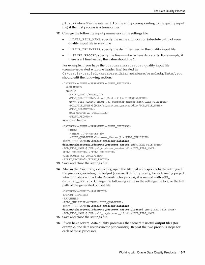
The Data Quality Process
Working with Oracle Data Quality Products 16-7
p1.stx (where N is the internal ID of the entity corresponding to the quality input file) if the first process is a transformer.
12. Change the following input parameters in the settings file:
■ In DATA_FILE_NAME, specify the name and location (absolute path) of your quality input file in run-time.
■ In FILE_DELIMITER, specify the delimiter used in the quality input file.
■ In START_RECORD, specify the line number where data starts. For example, if there is a 1 line header, the value should be 2.
For example, if you have the customer_master.csv quality input file (comma-separated with one header line) located in C:/oracle/oracledq/metabase_data/metabase/oracledq/Data/, you should edit the following section:
<CATEGORY><INPUT><PARAMETER><INPUT_SETTINGS> <ARGUMENTS> <ENTRY> <ENTRY_ID>1</ENTRY_ID> <FILE_QUALIFIER>Customer_Master(1)</FILE_QUALIFIER> <DATA_FILE_NAME>$(INPUT)/e1_customer_master.dat</DATA_FILE_NAME> <DDL_FILE_NAME>$(DDL)/e1_customer_master.ddx</DDL_FILE_NAME> <FILE_DELIMITER/> <USE_QUOTES_AS_QUALIFIER/> <START_RECORD/>as shown below:
<CATEGORY><INPUT><PARAMETER><INPUT_SETTINGS> <ENTRY> <ENTRY_ID>1</ENTRY_ID> <FILE_QUALIFIER>Customer_Master(1)</FILE_QUALIFIER><DATA_FILE_NAME>C:\oracle\oracledq\metabase_data\metabase\oracledq\Data\customer_master.csv</DATA_FILE_NAME><DDL_FILE_NAME>$(DDL)/e1_customer_master.ddx</DDL_FILE_NAME><FILE_DELIMITER>,</FILE_DELIMITER><USE_QUOTES_AS_QUALIFIER/><START_RECORD>2</START_RECORD>
13. Save and close the settings file.
14. Also in the /settings directory, open the file that corresponds to the settings of the process generating the output (cleansed) data. Typically, for a cleansing project which finishes with a Data Reconstructor process, it is named with eNN_datarec_pXX.stx. Change the following value in the settings file to give the full path of the generated output file.
<CATEGORY><OUTPUT><PARAMETER><OUTPUT_SETTINGS><ARGUMENTS><FILE_QUALIFIER>OUTPUT</FILE_QUALIFIER><DATA_FILE_NAME>C:\oracle\oracledq\metabase_data\metabase\oracledq\Data\customer_master_cleansed.csv</DATA_FILE_NAME><DDL_FILE_NAME>$(DDL)/e36_us_datarec_p11.ddx</DDL_FILE_NAME>
15. Save and close the settings file.
16. If you have several data quality processes that generate useful output files (for example, one data reconstructor per country). Repeat the two previous steps for each of these processes.
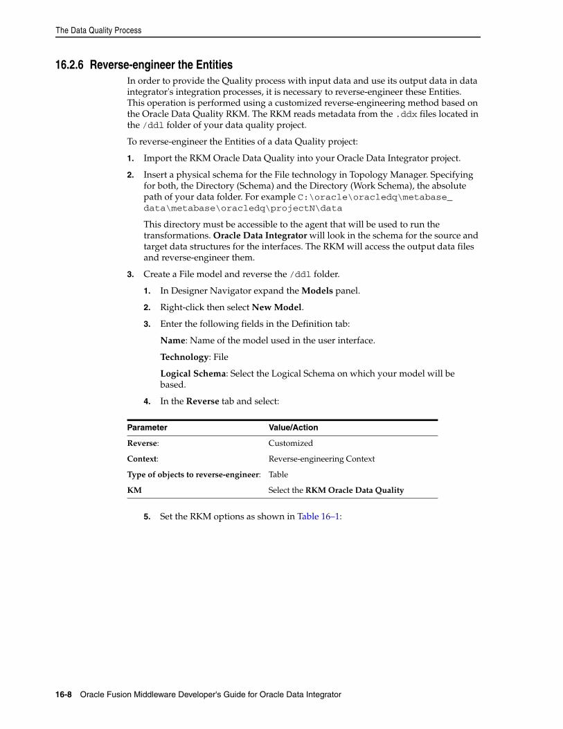
The Data Quality Process
16-8 Oracle Fusion Middleware Developer's Guide for Oracle Data Integrator
16.2.6 Reverse-engineer the EntitiesIn order to provide the Quality process with input data and use its output data in data integrator's integration processes, it is necessary to reverse-engineer these Entities. This operation is performed using a customized reverse-engineering method based on the Oracle Data Quality RKM. The RKM reads metadata from the .ddx files located in the /ddl folder of your data quality project.
To reverse-engineer the Entities of a data Quality project:
1. Import the RKM Oracle Data Quality into your Oracle Data Integrator project.
2. Insert a physical schema for the File technology in Topology Manager. Specifying for both, the Directory (Schema) and the Directory (Work Schema), the absolute path of your data folder. For example C:\oracle\oracledq\metabase_data\metabase\oracledq\projectN\data
This directory must be accessible to the agent that will be used to run the transformations. Oracle Data Integrator will look in the schema for the source and target data structures for the interfaces. The RKM will access the output data files and reverse-engineer them.
3. Create a File model and reverse the /ddl folder.
1. In Designer Navigator expand the Models panel.
2. Right-click then select New Model.
3. Enter the following fields in the Definition tab:
Name: Name of the model used in the user interface.
Technology: File
Logical Schema: Select the Logical Schema on which your model will be based.
4. In the Reverse tab and select:
5. Set the RKM options as shown in Table 16–1:
Parameter Value/Action
Reverse: Customized
Context: Reverse-engineering Context
Type of objects to reverse-engineer: Table
KM Select the RKM Oracle Data Quality
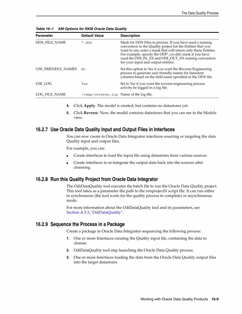
The Data Quality Process
Working with Oracle Data Quality Products 16-9
4. Click Apply. The model is created, but contains no datastores yet.
5. Click Reverse. Now, the model contains datastores that you can see in the Models view.
16.2.7 Use Oracle Data Quality Input and Output Files in InterfacesYou can now create in Oracle Data Integrator interfaces sourcing or targeting the data Quality input and output files.
For example, you can:
■ Create interfaces to load the input file using datastores from various sources.
■ Create interfaces to re-integrate the output data back into the sources after cleansing.
16.2.8 Run this Quality Project from Oracle Data Integrator The OdiDataQuality tool executes the batch file to run the Oracle Data Quality project. This tool takes as a parameter the path to the runprojectN script file. It can run either in synchronous (the tool waits for the quality process to complete) or asynchronous mode.
For more information about the OdiDataQuality tool and its parameters, see Section A.5.3, "OdiDataQuality".
16.2.9 Sequence the Process in a PackageCreate a package in Oracle Data Integrator sequencing the following process:
1. One or more Interfaces creating the Quality input file, containing the data to cleanse.
2. OdiDataQuality tool step launching the Oracle Data Quality process.
3. One or more Interfaces loading the data from the Oracle Data Quality output files into the target datastores.
Table 16–1 KM Options for RKM Oracle Data Quality
Parameter Default Value Description
DDX_FILE_NAME *.ddx Mask for DDX Files to process. If you have used a naming convention in the Quality project for the Entities that you want to use, enter a mask that will return only these Entities. For example, specify the ODI*_csv.ddx mask if you have used the ODI_IN_XX and ODI_OUT_XX naming convention for your input and output entities.
USE_FRIENDLY_NAMES No Set this option to Yes if you want the Reverse-Engineering process to generate user-friendly names for datastore columns based on the field name specified in the DDX file.
USE_LOG Yes Set to Yes if you want the reverse-engineering process activity be logged in a log file.
LOG_FILE_NAME /temp/reverse.log Name of the log file.

The Data Quality Process
16-10 Oracle Fusion Middleware Developer's Guide for Oracle Data Integrator
Part VPart V Managing Integration Projects
This part describes how to organize and maintain your Oracle Data Integrator projects.
This part contains the following chapters:
■ Chapter 17, "Organizing and Documenting your Work"
■ Chapter 18, "Working with Version Management"
■ Chapter 19, "Exporting/Importing"

17
Organizing and Documenting your Work 17-1
17Organizing and Documenting your Work
This chapter describes how to organize and document your work in Oracle Data Integrator.
This chapter includes the following sections:
■ Section 17.1, "Organizing Projects with Folders"
■ Section 17.2, "Organizing Models with Folders"
■ Section 17.3, "Using Cross-References"
■ Section 17.4, "Using Markers and Memos"
■ Section 17.5, "Handling Concurrent Changes"
■ Section 17.6, "Creating PDF Reports"
17.1 Organizing Projects with FoldersBefore you begin creating an integration project with Oracle Data Integrator, it is recommended to think about how the project will be organized.
Rearranging your project afterwards may be dangerous. You might have to redo all the links and cross-references manually to reflect new locations.
Within a project, interfaces, procedures and packages are organized into folders and sub-folders. It is recommended to maintain your project well organized by grouping related project components into folders and sub-folders according to criteria specific to the project. Folders simplify finding objects developed in the project and facilitate the maintenance tasks. Sub-folders can be created to an unlimited number of levels.
Note that you can also use markers to organize your projects. Refer to Section 17.4, "Using Markers and Memos" for more information.
17.1.1 Creating a New FolderTo create a new folder:
1. In Designer Navigator expand the Projects accordion.
2. Select the project into which you want to add a folder.
3. Right-click and select New Folder.
4. In the Name field, enter a name for your folder.
5. Select Save from the File main menu.
The empty folder appears.
Organizing Models with Folders
17-2 Oracle Fusion Middleware Developer's Guide for Oracle Data Integrator
To create a sub-folder:
1. Create a new folder as described in Section 17.1.1, "Creating a New Folder".
2. Drag and drop the new folder into the parent folder.
17.1.2 Arranging Project FoldersTo arrange your project folders in the project hierarchy, drag and drop a folder into other folders or on the Project. Note that it is not possible to move a folder from one Project to another Project.
17.2 Organizing Models with FoldersA model folder groups related models according to criteria specific to the project. A model folder may also contain other model folders. Sub-folders can be created to an unlimited number of levels.
Note that you can also use markers to organize your models. Refer to Section 17.4, "Using Markers and Memos" for more information.
17.2.1 Creating a New Model FolderTo create a model folder:
1. In Designer Navigator expand the Models accordion.
2. Click New Model Folder in the toolbar of the Models accordion.
3. In the Name field, enter a name for your folder.
4. Select Save from the File main menu.
The empty model folder appears.
17.2.2 Arranging Model FoldersTo move a model into a folder:
1. In Designer Navigator expand the Models accordion.
2. Select the model, then drag and drop it on the icon of the destination model folder.
The model moves from its current location to the selected model folder.
Note the following when arranging model folders:
■ A model can only be in one folder at a time.
■ Model folders can be also moved into other model folders.
17.2.3 Creating and Organizing Sub-ModelsA sub-model is an object that allows you to organize and classify the datastores of a model in a hierarchical structure. The root of the structure is the model. A sub-model groups functionally homogeneous datastores within a model. The datastores of a model can be inserted into a sub-model using drag and drop, or by automatic distribution.
The classification is performed:
Organizing Models with Folders
Organizing and Documenting your Work 17-3
■ During the reverse-engineering process, the RKM may create sub-models and automatically distribute datastores into these sub-models. For example RKM handling large data models from ERP systems use this method.
■ Manually, by drag and dropping existing datastores into the sub-models.
■ Automatically, using the distribution based on the datastore’s name.
To create a sub-model:
1. In Designer Navigator expand the Models accordion.
2. In the Models accordion, select the model or the sub-model into which you want to add a sub-model.
3. Right-click and select New Sub-Model.
4. On the Definition tab, enter a name for your sub-model in the Name field.
5. Click OK.
The new sub-model is created with no datastore.
Arranging Sub-ModelsTo manually file a datastore into a sub-model:
1. In Designer Navigator expand the Models accordion.
2. In the Models accordion, select the datastore you wan to move into the sub-folder.
3. Drag and drop it into the sub-model.
The datastore disappears from the model and appears in the sub-model.
Setting-up Automatic DistributionDistribution allows you to define an automatic distribution of the datastores in your sub-models.
Datastores names are compared to the automatic assignment mask. If they match this pattern, then they are moved into this sub-model. This operation can be performed manually or automatically depending on the Datastore Distribution Rule.
There are two methods to classify:
■ By clicking Distribution in the Distribution tab of a sub-model, the current rule is applied to the datastores.
■ At the end of a reverse-engineering process, all sub-model rules are applied, the order defined by the Order of mask application after a Reverse Engineer values for all sub-models.
To set up the automatic distribution of the datastores in a sub-model:
1. In the sub-model's Distribution tab, select the Datastore distribution rule:
The Datastore Distribution rule determines which datastores will be taken into account and compared to the automatic assignment mask:
– No automatic distribution: No datastore is taken in account. Distribution must be made manually.
– Automatic Distribution of all Datastores not already in a Sub-Model: Datastores located in the root model in the sub-model tree are taken in account.
Using Cross-References
17-4 Oracle Fusion Middleware Developer's Guide for Oracle Data Integrator
– Automatic Distribution of all Datastores: All datastores in the model (and sub-models) are taken in account.
2. In the Automatic Assignment Mask field, enter the pattern the datastore names must match to be classified into this sub-model.
3. In the Order of mask application after a Reverse Engineer field, enter the order in which all rules should be applied at the end of a reverse. Consequently, a rule with a high order on all datastores will have precedence. A rule with a high order on non-classified datastores will apply only to datastores ignored by the other rules' patterns. At the end of the reverse, new datastores are considered non classified. Those already classified in a sub-model stay attached to their sub-model.
4. Click Distribution. The current rule is applied to the datastores.
17.3 Using Cross-ReferencesObjects in Oracle Data Integrator (datastores, models, interfaces, etc) are interlinked by relationships varying from simple usage associations (an integration interface uses Knowledge Modules) to complex ones such as code-interpretation relationships (a variable is used in the mappings or filters of an interface). These relationships are implemented as cross-references. They are used to check/maintain consistency between related objects within a work repository. Cross-references, for example, prevent you from deleting an object if it is currently referenced elsewhere in the work repository.
Not all relationships appear as cross-references:
■ Relationships with objects from the master repository (For example, a data model is related to a technology) are not implemented as cross-references, but as loose references based on object codes (context code, technology code, datatype code, etc). Modifications to these codes may cause inconsistency in the references.
■ Strong relationships in the work repository (a folder belongs to a project) are enforced in the graphical user interface and within the repository (in the host database as foreign keys). These relationships may not normally be broken.
17.3.1 Browsing Cross-ReferencesWhen modifying an object, it is necessary to analyze the impact of these changes on other developments. For example, if the length of a column is altered, the integration interfaces using this column as a source or a target may require modification. Cross-references enable you to immediately identify the objects referenced or referencing a given object, and in this way provide effective impact analysis.
Cross-references may be browsed in Designer Navigator as described in Table 17–1.
Table 17–1 Cross-References in Designer Navigator
Accordion Icon Description
Projects and Other accordion
The Used in and Used by nodes appear under an object node. The Used in node lists the objects from which the current object is referenced. In the case of a variable, for example, the packages containing steps referencing this variable and the interfaces using this variable in the mappings, filters, etc. will be displayed. The Used by node lists the objects that are using the current object.
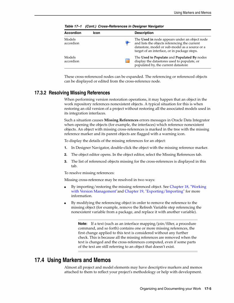
Using Markers and Memos
Organizing and Documenting your Work 17-5
These cross-referenced nodes can be expanded. The referencing or referenced objects can be displayed or edited from the cross-reference node.
17.3.2 Resolving Missing ReferencesWhen performing version restoration operations, it may happen that an object in the work repository references nonexistent objects. A typical situation for this is when restoring an old version of a project without restoring all the associated models used in its integration interfaces.
Such a situation causes Missing References errors messages in Oracle Data Integrator when opening the objects (for example, the interfaces) which reference nonexistent objects. An object with missing cross-references is marked in the tree with the missing reference marker and its parent objects are flagged with a warning icon.
To display the details of the missing references for an object:
1. In Designer Navigator, double-click the object with the missing reference marker.
2. The object editor opens. In the object editor, select the Missing References tab.
3. The list of referenced objects missing for the cross-references is displayed in this tab.
To resolve missing references:
Missing cross-reference may be resolved in two ways:
■ By importing/restoring the missing referenced object. See Chapter 18, "Working with Version Management"and Chapter 19, "Exporting/Importing" for more information.
■ By modifying the referencing object in order to remove the reference to the missing object (for example, remove the Refresh Variable step referencing the nonexistent variable from a package, and replace it with another variable).
17.4 Using Markers and MemosAlmost all project and model elements may have descriptive markers and memos attached to them to reflect your project's methodology or help with development.
Models accordion
The Used in node appears under an object node and lists the objects referencing the current datastore, model or sub-model as a source or a target of an interface, or in package steps.
Models accordion
The Used to Populate and Populated By nodes display the datastores used to populate, or populated by, the current datastore
Note: If a text (such as an interface mapping/join/filter, a procedure command, and so forth) contains one or more missing references, the first change applied to this text is considered without any further check. This is because all the missing references are removed when the text is changed and the cross-references computed, even if some parts of the text are still referring to an object that doesn't exist.
Table 17–1 (Cont.) Cross-References in Designer Navigator
Accordion Icon Description
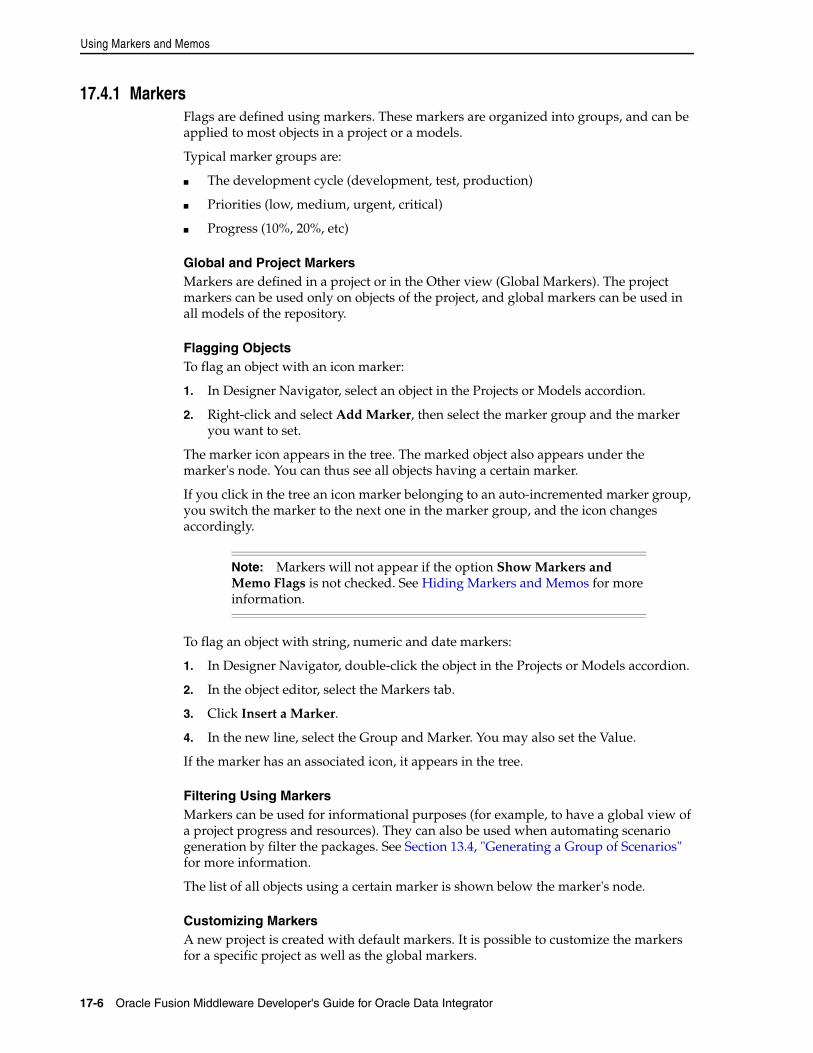
Using Markers and Memos
17-6 Oracle Fusion Middleware Developer's Guide for Oracle Data Integrator
17.4.1 MarkersFlags are defined using markers. These markers are organized into groups, and can be applied to most objects in a project or a models.
Typical marker groups are:
■ The development cycle (development, test, production)
■ Priorities (low, medium, urgent, critical)
■ Progress (10%, 20%, etc)
Global and Project MarkersMarkers are defined in a project or in the Other view (Global Markers). The project markers can be used only on objects of the project, and global markers can be used in all models of the repository.
Flagging ObjectsTo flag an object with an icon marker:
1. In Designer Navigator, select an object in the Projects or Models accordion.
2. Right-click and select Add Marker, then select the marker group and the marker you want to set.
The marker icon appears in the tree. The marked object also appears under the marker's node. You can thus see all objects having a certain marker.
If you click in the tree an icon marker belonging to an auto-incremented marker group, you switch the marker to the next one in the marker group, and the icon changes accordingly.
To flag an object with string, numeric and date markers:
1. In Designer Navigator, double-click the object in the Projects or Models accordion.
2. In the object editor, select the Markers tab.
3. Click Insert a Marker.
4. In the new line, select the Group and Marker. You may also set the Value.
If the marker has an associated icon, it appears in the tree.
Filtering Using MarkersMarkers can be used for informational purposes (for example, to have a global view of a project progress and resources). They can also be used when automating scenario generation by filter the packages. See Section 13.4, "Generating a Group of Scenarios" for more information.
The list of all objects using a certain marker is shown below the marker's node.
Customizing MarkersA new project is created with default markers. It is possible to customize the markers for a specific project as well as the global markers.
Note: Markers will not appear if the option Show Markers and Memo Flags is not checked. See Hiding Markers and Memos for more information.
Handling Concurrent Changes
Organizing and Documenting your Work 17-7
To define a marker group:
1. In Designer Navigator, click the Markers node in the Project accordion, or the Global Markers node in the Others accordion.
2. Right-click and select New Marker Group.
3. In the Group Name field, enter the name for the marker group, then define its Display Properties and Attributes.
4. Click Insert a new Marker to create a new marker in the group.
5. Select the marker Icon. If a marker stores date or a number, the icon should be set to <none>.
6. Select the marker Name, Type and other options.
7. Repeat operations 4 to 6 to add more markers to the group.
8. Select Save from the File main menu.
17.4.2 MemosA memo is an unlimited amount of text attached to virtually any object, visible on its Memo tab. When an object has a memo attached, the memo icon appears next to it.
To edit an object's memo:
1. Right-click the object.
2. Select Edit Memo.
3. The Object editor opens, and the Memo tab is selected.
Hiding Markers and MemosYou can temporarily hide all markers and memo flags from the tree views, to improve readability.
To hide all markers and memo flags:
Deselect the Display Markers and Memo Flags option in the Designer Navigator toolbar menu. This preference is stored on a per-machine basis.
17.5 Handling Concurrent ChangesSeveral users can work simultaneously in the same Oracle Data Integrator project or model. As they may be all connected to the same repository, the changes they perform are considered as concurrent.
Oracle Data Integrator provides two methods for handling these concurrent changes: Concurrent Editing Check and Object Locking. This two methods can be used simultaneously or separately.
17.5.1 Concurrent Editing CheckThe user parameter, Check for concurrent editing, can be set to 1 to perform to prevent you from erasing the work performed by another user on the object you try to save. Refer to Appendix B, "User Parameters" for more information.
If this parameter is set to 1, when saving changes to any object, Oracle Data Integrator checks whether other changes have been made to the same object by another user since you opened it. If another user has made changes, the object cannot be saved, and you must cancel your changes.
Handling Concurrent Changes
17-8 Oracle Fusion Middleware Developer's Guide for Oracle Data Integrator
17.5.2 Object LockingThe object locking mechanism can be activated in Oracle Data Integrator automatically, when closing the Oracle Data Integrator or manually.
Automatic Object LockingThis mechanism is automatically activated. When an object is opened in a user interface, a popup window appears to ask if you want to lock the object. As long as an object is locked, only the user owning the lock can perform modifying the object, such as editing or deleting. Other operations, such as executing, can be performed by other users, but with a warning.
An object locked by you appears with a yellow lock icon. An object locked by another user appears with a red lock icon.
When the edition window is closed, a popup window appears to ask if you want to unlock the object.
Note that these windows are configured by the Lock object when opening and Unlock object when closing user parameters. See Appendix B, "User Parameters" for more information.
Releasing locks when closing the user interfaceWhen closing Oracle Data Integrator, a window appears asking to unlock or save objects that you have locked or kept opened.
You can keep objects locked even if you are not connected to Oracle Data Integrator. This allows you to prevent other users from editing them in the meanwhile.
Managing manually locksYou can also manually manage locks on objects.
To manually lock an object:
1. Select the object in the tree.
2. Right-click, then select Locks > Lock.
A lock icon appears after the object in the tree.
To manually unlock an object:
1. Select the object in the tree
2. Right-click, then select Locks > Unlock.
The lock icon disappears in the tree.
To manage all locks:
1. Select Locked objects from the ODI menu.
2. The Locked Objects editor appears displaying all locked objects that you can unlock.
Note: A user with the Supervisor privilege can remove locks for all other users.
Creating PDF Reports
Organizing and Documenting your Work 17-9
17.6 Creating PDF ReportsIn Oracle Data Integrator you have the possibility to print and share several types of reports with the PDF generation feature:
■ Topology reports of the physical architecture, the logical architecture, or the contexts
■ Reports of the version comparison results.
■ Reports of an ODI object
■ Diagram reports
17.6.1 Generating a Topology ReportOracle Data Integrator provides the possibility to generate Topology reports in PDF format of the physical architecture, the logical architecture or the contexts.
To generate a topology report:
1. From the Topology Navigator toolbar menu select Generate Report and then the type of report you wish to generate:
■ Physical Architecture
■ Logical Architecture
■ Contexts
2. In the Report generation editor, enter the output PDF file location for your PDF report. Note that if no PDF file location is specified, the report in Adobe™ PDF format is generated in your default directory for pdf generation specified in the user parameters. Refer to Appendix B, "User Parameters" for more information.
3. If you want to view the PDF report after generation, select the Open file after the generation? option.
4. Click Generate.
17.6.2 Generating a Report for the Version Comparison ResultsYou can create and print a report of your comparison results via the Version Comparison Tool. Refer to the Section 18.3.3, "Generating and Printing a Report of your Comparison Results" for more information.
17.6.3 Generating a Report for an Oracle Data Integrator ObjectIn Designer Navigator you can generate different types of reports depending on the type of object. Table 17–2 lists the different report types for ODI objects.
Note: In order to view the generated reports, you must specify the location of Acrobat® Reader™ in the Appendix B, "User Parameters" before launching the PDF generation.
Table 17–2 Different report types for ODI objects
Object Reports
Project Knowledge Modules
Project Folder Folder, Packages, Interfaces, Procedures
Creating PDF Reports
17-10 Oracle Fusion Middleware Developer's Guide for Oracle Data Integrator
To generate a report in Designer Navigator:
1. In Designer Navigator, select the object for which you wish to generate a report.
2. Right-click and select Print >Print <object>.
3. In the Report generation editor, enter the output PDF file location for your PDF report. Note that if no PDF file location is specified, the report in Adobe™ PDF format is generated in your default directory for pdf generation specified in the user parameters. Refer to Appendix B, "User Parameters" for more information.
4. If you want to view the PDF report after generation, select the Open file after the generation? option.
5. Click Generate.
17.6.4 Generating a Diagram ReportYou can generate a complete PDF report of your diagram. Refer to Section 6.2.5, "Printing a Diagram" for more information.
Model Folder Model Folder
Model Model
Sub-model Sub-model
Table 17–2 (Cont.) Different report types for ODI objects
Object Reports
18
Working with Version Management 18-1
18Working with Version Management
This chapter describes how to work with version management in Oracle Data Integrator.
Oracle Data Integrator provides a comprehensive system for managing and safeguarding changes. The version management system allows flags on developed objects (such as projects, models, etc) to be automatically set, to indicate their status, such as new or modified. It also allows these objects to be backed up as stable checkpoints, and later restored from these checkpoints. These checkpoints are created for individual objects in the form of versions, and for consistent groups of objects in the form of solutions.
This chapter includes the following sections:
■ Section 18.1, "Working with Object Flags"
■ Section 18.2, "Working with Versions"
■ Section 18.3, "Working with the Version Comparison Tool"
■ Section 18.4, "Working with Solutions"
18.1 Working with Object FlagsWhen an object is created or modified in Designer Navigator, a flag is displayed in the tree on the object icon to indicate its status. Table 18–1 lists these flags.
Note: Version management is supported for master repositories installed on database engines such as Oracle, Hypersonic SQL, and Microsoft SQL Server. For a complete list of certified database engines supporting version management refer to the Platform Certifications document on OTN at: http://www.oracle.com/technology/products/oracle-data-integrator/index.html.
Table 18–1 Object Flags
Flag Description
Object status is inserted.
Object status is updated.
Working with Versions
18-2 Oracle Fusion Middleware Developer's Guide for Oracle Data Integrator
When an object is inserted, updated or deleted, its parent objects are recursively flagged as updated. For example, when a step is inserted into a package, it is flagged as inserted, and the package, folder(s) and project containing this step are flagged as updated.
When an object version is checked in (Refer to Section 18.2, "Working with Versions" for more information.), the flags on this object are reset.
18.2 Working with VersionsA version is a backup copy of an object. It is checked in at a given time and may be restored later. Versions are saved in the master repository. They are displayed in the Version tab of the object window.
The following objects can be checked in as versions:
■ Project, Folder
■ Package, Scenario
■ Interface, Procedure, Knowledge Module
■ Sequence, User Function, Variable
■ Model, Model Folder
■ Solution
■ Load Plan
Checking in a versionTo check in a version:
1. Select the object for which you want to check in a version.
2. Right-click, then select Version > Create...
3. In the Create dialog, click Previous Versions (>>) to expand the list of versions already checked in.
4. A version number is automatically generated in the Version field. Modify this version number if necessary.
5. Enter the details for this version in the Description field.
6. Click OK.
When a version is checked in, the flags for the object are reset.
Displaying previous versions of an objectTo display previous versions of an object:
When editing the object, the Version tab provides a list of versions checked in, with the check in date and the name of the user who performed the check in operation.
Restoring a versionTo restore a version:
1. Select the object for which you want to restore a version.
2. Right-click, then select Version > Restore...
3. The Restore dialog displays the list of existing versions.
Working with Versions
Working with Version Management 18-3
4. Select the version you want to restore and click OK.
5. Click OK to confirm the restore operation.
Browsing versionsTo browse versions:
Oracle Data Integrator contains a tool, the Version Browser, which is used to display the versions stored in the repository.
1. From the main menu, select ODI > Version Browser...
2. Use the object Type and object Name drop-down lists to filter the objects for which you want to display the list of versions.
From the Version Browser, you can restore a version, export a version as an XML file or delete an existing version.
Deleting a version with the Version BrowserTo delete a version with the Version Browser:
1. Open the Version Browser.
2. Select the version you want to delete.
3. Right-click, then select Delete.
The version is deleted.
Restoring a version with the Version BrowserTo restore a version with the Version Browser:
1. Open the Version Browser.
2. Select the version you want to restore.
3. Right-click, then select Restore.
4. Click OK to confirm the restore operation.
The version is restored in the repository.
Exporting a version with the Version BrowserTo export a version with the Version Browser:
This operation exports the version to a file without restoring it. This export can be imported in another repository.
WARNING: Restoring a version cannot be undone. It permanently erases the current object and replaces it by the selected version.
Note: The Version Browser displays the versions that existed when you opened it. Click Refresh to view all new versions created since then.
Note: Exporting a version, exports the object contained in the version and not the version information. This allows you exporting an old version without having to actually restore it in the repository.
Working with the Version Comparison Tool
18-4 Oracle Fusion Middleware Developer's Guide for Oracle Data Integrator
1. Open the Version Browser.
2. Select the version you want to export.
3. Right-click, then select Export.
4. Select the Export Directory and specify the Export Name. Select Replace Existing Files without Warning to erase existing export files without confirmation.
5. Click OK.
The version is exported to the given location.
18.3 Working with the Version Comparison ToolOracle Data Integrator provides a comprehensive version comparison tool. This graphical tool is to view and compare two different versions of an object.
The version comparison tool provides the following features:
■ Color-coded side-by-side display of comparison results: The comparison results are displayed in two panes, side-by-side, and the differences between the two compared versions are color coded.
■ Comparison results organized in tree: The tree of the comparison tool displays the comparison results in a hierarchical list of node objects in which expanding and collapsing the nodes is synchronized.
■ Report creation and printing in PDF format: The version comparison tool is able to generate and print a PDF report listing the differences between two particular versions of an object.
■ Supported objects: The version comparison tool supports the following objects: Project, Folder, Package, Scenario, Interface, Procedure, Knowledge Module, Sequence, User Function, Variable, Model, Model folder, and Solution.
■ Difference viewer functionality: This version comparison tool is a difference viewer and is provided only for consultation purposes. Editing or merging object versions is not supported. If you want to edit the object or merge the changes between two versions, you have to make the changes manually directly in the concerned objects.
18.3.1 Viewing the Differences between two VersionsTo view the differences between two particular versions of an object, open the Version Comparison tool.
There are three different way of opening the version comparison tool:
By selecting the object in the Projects tree1. From the Projects tree in Designer Navigator, select the object whose versions you
want to compare.
2. Right-click the object.
3. Select Version > Compare with version...
4. In the Compare with version editor, select the version with which you want to compare the current version of the object.
5. Click OK.
6. The Version Comparison tool opens.
Working with the Version Comparison Tool
Working with Version Management 18-5
Via the Versions tab of the object1. In Designer Navigator, open the object editor of the object whose versions you
want to compare.
2. Go to the Version tab.
The Version tab provides the list of all versions created for this object. This list also indicates the creation date, the name of the user who created the version, and a description (if specified).
3. Select the two versions you want to compare by keeping the <CTRL> key pressed.
4. Right-click and select Compare...
5. The Version Comparison tool opens.
Via the Version Browser1. From the main menu, select ODI > Version Browser...
2. Select the two versions you want to compare. Note that you can compare only versions of the same object.
3. Right-click and select Compare...
4. The Version Comparison tool opens.
The Version Comparison tool shows the differences between two versions: on the left pane the newer version and on the right pane the older version of your selected object.
The differences are color highlighted. The following color code is applied:
18.3.2 Using Comparison FiltersOnce the version of an object is created, the Version Comparison tool can be used at different points in time.
Creating or checking in a version is covered in the topic Working with Versions.
The Version Comparison tool provides two different types of filters for customizing the comparison results:
■ Object filters: By selecting the corresponding check boxes (New and/or Deleted and/or Modified and/or Unchanged) you can decide whether you want only newly added and/or deleted and/or modified and/or unchanged objects to be displayed.
Color Description
White (default) unchanged
Red deleted
Green added/new
Yellow object modified
Orange field modified (the value inside of this fields has changed)
Note: If one object does not exist in one of the versions (for example, when it has been deleted), it is represented as an empty object (with empty values).
Working with Solutions
18-6 Oracle Fusion Middleware Developer's Guide for Oracle Data Integrator
■ Field filters: By selecting the corresponding check boxes (New and/or Deleted and/or Modified and/or Unchanged) you can decide whether you want newly added fields and/or deleted fields and/or modified fields and/or unchanged fields to be displayed.
18.3.3 Generating and Printing a Report of your Comparison ResultsTo generate a report of your comparison results in Designer Navigator:
1. In the Version Comparison tool, click the Printer icon.
2. In the Report Generation dialog, set the object and field filters according to your needs.
3. In the PDF file location field, specify a file name to write the report to. If no path is specified, the file will be written to the default directory for PDF files. This is a user preference.
4. Check the box next to Open file after generation if you want to view the file after its generation.
Select Open the file after the generation to view the generated report in Acrobat® Reader™ .
5. Click Generate.
A report in Adobe™ PDF format is written to the file specified in step 3.
18.4 Working with SolutionsA solution is a comprehensive and consistent set of interdependent versions of objects. Like other objects, it can be checked in at a given time as a version, and may be restored at a later date. Solutions are saved into the master repository. A solution assembles a group of versions called the solution's elements.
A solution is automatically assembled using cross-references. By scanning cross-references, a solution automatically includes all dependant objects required for a particular object. For example, when adding a project to a solution, versions for all the models used in this project's interfaces are automatically checked in and added to the solution. You can also manually add or remove elements into and from the solution.
Solutions are displayed in the Solutions accordion in Designer Navigator and in Operator Navigator.
The following objects may be added into solutions:
■ Projects
■ Models, Model Folders
■ Scenarios
■ Load Plans
■ Global Variables, User Functions and Sequences.
To create a solution:
Note: In order to view the generated report, you must specify the location of Acrobat® Reader™ in the user parameters. Refer to Appendix B, "User Parameters" for more information.
Working with Solutions
Working with Version Management 18-7
1. In Designer Navigator or Operator Navigator, from the Solutions toolbar menu select New Solution.
2. In the Solutions editor, enter the Name of your solution and a Description.
3. From the File menu select Save.
The resulting solution is an empty shell into which elements may then be added.
18.4.1 Working with Elements in a SolutionThis section details the different actions that can be performed when working with elements of a solution.
Adding ElementsTo add an element, drag the object from the tree into the Elements list in the solution editor. Oracle Data Integrator scans the cross-references and adds any Required Elements needed for this element to work correctly. If the objects being added have been inserted or updated since their last checked in version, you will be prompted to create new versions for these objects.
Removing ElementsTo remove an element from a solution, select the element you want to remove in the Elements list and then click the Delete button. This element disappears from the list. Existing checked in versions of the object are not affected.
Rolling Back ObjectsTo roll an object back to a version stored in the solution, select the elements you want to restore and then click the Restore button. The elements selected are all restored from the solution's versions.
18.4.2 Synchronizing SolutionsSynchronizing a solution automatically adds required elements that have not yet been included in the solution, creates new versions of modified elements and automatically removes unnecessary elements. The synchronization process brings the content of the solution up to date with the elements (projects, models, etc) stored in the repository.
To synchronize a solution:
1. Open the solution you want to synchronize.
2. Click Synchronize in the toolbar menu of the Elements section.
3. Oracle Data Integrator scans the cross-references. If the cross-reference indicates that the solution is up to date, then a message appears. Otherwise, a list of elements to add or remove from the solution is shown. These elements are grouped into Principal Elements (added manually), Required Elements (directly or indirectly referenced by the principal elements) and Unused Elements (no longer referenced by the principal elements).
4. Check the Accept boxes to version and include the required elements or delete the unused ones.
5. Click OK to synchronize the solution. Version creation windows may appear for elements requiring a new version to be created.
You should synchronize your solutions regularly to keep the solution contents up-to-date. You should also do it before checking in a solution version.
Working with Solutions
18-8 Oracle Fusion Middleware Developer's Guide for Oracle Data Integrator
18.4.3 Restoring and Checking in a SolutionThe procedure for checking in and restoring a solution version is similar to the method used for single elements. See Section 18.2, "Working with Versions" for more details.
You can also restore a solution to import scenarios into production in Operator Navigator or Designer Navigator.
To restore a scenario from a solution:
1. Double-click a solution to open the Solution editor.
2. Select a scenario from the Principal or Required Elements section. Note that other elements, such as projects and interfaces, cannot be restored.
3. Click Restore in the toolbar menu of the Elements section.
The scenario is now accessible in the Scenarios tab.
Note that you can also use the Version Browser to restore scenarios. See Restoring a version with the Version Browser.
18.4.4 Importing and Exporting SolutionsSolutions can be exported and imported similarly to other objects in Oracle Data Integrator. Export/Import is used to transfer solutions from one master repository to another. Refer to Chapter 19, "Exporting/Importing" for more information.
Note: When restoring a solution, elements in the solution are not automatically restored. They must be restored manually from the Solution editor.
19
Exporting/Importing 19-1
19Exporting/Importing
This chapter describes how to manage export and import operations in Oracle Data Integrator. An introduction to the import and export concepts is provided.
This chapter includes the following sections:
■ Section 19.1, "Import and Export Concepts"
■ Section 19.2, "Exporting and Importing Objects"
■ Section 19.3, "Repository-Level Export/Import"
■ Section 19.4, "Exporting the Technical Environment"
19.1 Import and Export ConceptsThis section introduces you to the fundamental concepts of export and import operations in Oracle Data Integrator. All export and import operations require a clear understanding of the concepts introduced in this section.
19.1.1 Internal Identifiers (IDs)Before performing export and import operations, it is essential to understand in detail the concept of internal identifiers (ID) in Oracle Data Integrator.
To ensure object uniqueness across several work repositories, ODI uses a specific mechanism to generate unique IDs for objects (such as technologies, data servers, Models, Projects, Integration Interfaces, KMs, etc.). Every object in Oracle Data Integrator is identified by an internal ID. The internal ID appears on the Version tab of each object.
ODI Master and Work Repositories are identified by their unique internal IDs. This RepositoryID of 3 digits must be unique across all work repositories of an ODI installation and is used to compute the internal ID of an object.
The internal ID of an object is calculated by appending the value of the RepositoryID to an automatically incremented number: <UniqueNumber><RepositoryID>
If the Repository ID is shorter than 3 digits, the missing digits are completed with "0". For example, if a repository has the ID 5, possible internal IDs of the objects in this repository could be: 1005, 2005, 3005, ..., 1234567005. Note that all objects created within the same repository have the same three last digits, in this example 005.
This internal ID is unique for the object type within the repository and also unique between repositories for the object type because it contains the repository unique ID. This mechanism allows to:
Import and Export Concepts
19-2 Oracle Fusion Middleware Developer's Guide for Oracle Data Integrator
■ Avoid any ID conflicts when exporting and importing from one repository to another
■ Understand the provenance of every object, simply by looking at its Internal ID. The 3 last digits always refer to the repository where it was created.
Important Export/Import Rules and GuidelinesDue to the structure of the object IDs, these guidelines should be followed:
■ Work repositories must always have different internal IDs. Work repositories with the same ID are considered to contain same objects.
■ If an export/import operation is performed between two Master/Work repositories possessing identical internal IDs, there is a risk of overwriting objects when importing. Objects from both repositories that have same IDs are considered the same.
19.1.2 Relationships between ObjectsOracle Data Integrator stores all objects in a relational database schema (the Repository) with dependencies between objects. Repository tables that store these objects maintain these dependencies as references using the IDs. When you drag and drop a target datastore into an integration interface, only the reference to the ID of this datastore is stored in the interface object. If you want to export this interface, and import it in Synonym mode into another work repository, a datastore with the same ID must already exist in this other work repository otherwise the import will create a missing reference. The missing references can be resolved either by fixing the imported object directly or by importing the missing object.
Solutions allow to export and import sets of dependent objects automatically. Using solutions and versioning is the recommended way of maintaining the dependencies automatically when doing export/import. See Chapter 18, "Working with Version Management".
Therefore, the Model or Sub-model holding this Datastore needs to be exported and imported in Synonym mode prior to importing the integration interface.
There are also dependencies between work repository objects and master repository objects. Dependencies within a work repository are ID-based. Dependencies between objects of the work and objects of the master are based on the Codes and not the IDs. This means that only the Code of the objects (for example ORACLE is the code of the Oracle technology in the master) of the master repository objects are referenced in the work repository.
It is important to import objects in the appropriate order. You can also use Solutions to preserve these dependencies. Table 19–1 lists the dependencies of an integration interface to other objects when importing the integration interface in synonym mode.
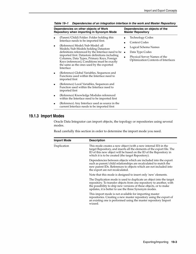
Import and Export Concepts
Exporting/Importing 19-3
19.1.3 Import ModesOracle Data Integrator can import objects, the topology or repositories using several modes.
Read carefully this section in order to determine the import mode you need.
Table 19–1 Dependencies of an integration interface in the work and Master Repository
Dependencies on other objects of Work Repository when importing in Synonym Mode
Dependencies on objects of the Master Repository
■ (Parent/Child) Folder: Folder holding this Interface needs to be imported first.
■ (Reference) Model/Sub-Model: all Models/Sub-Models holding Datastore definitions referenced by the Interface need to be imported first. Datastore definitions including Columns, Data Types, Primary Keys, Foreign Keys (references), Conditions must be exactly the same as the ones used by the exported Interface
■ (Reference) Global Variables, Sequences and Functions used within the Interface need to imported first
■ (Reference) Local Variables, Sequences and Function used within the Interface need to imported first
■ (Reference) Knowledge Modules referenced within the Interface need to be imported first
■ (Reference) Any Interface used as source in the current Interface needs to be imported first
■ Technology Codes
■ Context Codes
■ Logical Schema Names
■ Data Type Codes
■ Physical Server Names of the Optimization Contexts of Interfaces
Import Mode Description
Duplication This mode creates a new object (with a new internal ID) in the target Repository, and inserts all the elements of the export file. The ID of this new object will be based on the ID of the Repository in which it is to be created (the target Repository).
Dependencies between objects which are included into the export such as parent/child relationships are recalculated to match the new parent IDs. References to objects which are not included into the export are not recalculated.
Note that this mode is designed to insert only 'new' elements.
The Duplication mode is used to duplicate an object into the target repository. To transfer objects from one repository to another, with the possibility to ship new versions of these objects, or to make updates, it is better to use the three Synonym modes.
This import mode is not available for importing master repositories. Creating a new master repository using the export of an existing one is performed using the master repository Import wizard.
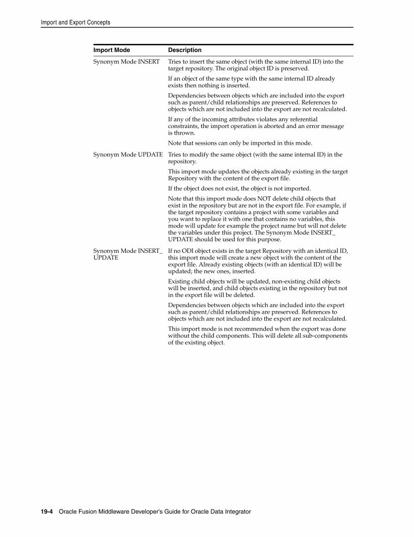
Import and Export Concepts
19-4 Oracle Fusion Middleware Developer's Guide for Oracle Data Integrator
Synonym Mode INSERT Tries to insert the same object (with the same internal ID) into the target repository. The original object ID is preserved.
If an object of the same type with the same internal ID already exists then nothing is inserted.
Dependencies between objects which are included into the export such as parent/child relationships are preserved. References to objects which are not included into the export are not recalculated.
If any of the incoming attributes violates any referential constraints, the import operation is aborted and an error message is thrown.
Note that sessions can only be imported in this mode.
Synonym Mode UPDATE Tries to modify the same object (with the same internal ID) in the repository.
This import mode updates the objects already existing in the target Repository with the content of the export file.
If the object does not exist, the object is not imported.
Note that this import mode does NOT delete child objects that exist in the repository but are not in the export file. For example, if the target repository contains a project with some variables and you want to replace it with one that contains no variables, this mode will update for example the project name but will not delete the variables under this project. The Synonym Mode INSERT_UPDATE should be used for this purpose.
Synonym Mode INSERT_UPDATE
If no ODI object exists in the target Repository with an identical ID, this import mode will create a new object with the content of the export file. Already existing objects (with an identical ID) will be updated; the new ones, inserted.
Existing child objects will be updated, non-existing child objects will be inserted, and child objects existing in the repository but not in the export file will be deleted.
Dependencies between objects which are included into the export such as parent/child relationships are preserved. References to objects which are not included into the export are not recalculated.
This import mode is not recommended when the export was done without the child components. This will delete all sub-components of the existing object.
Import Mode Description
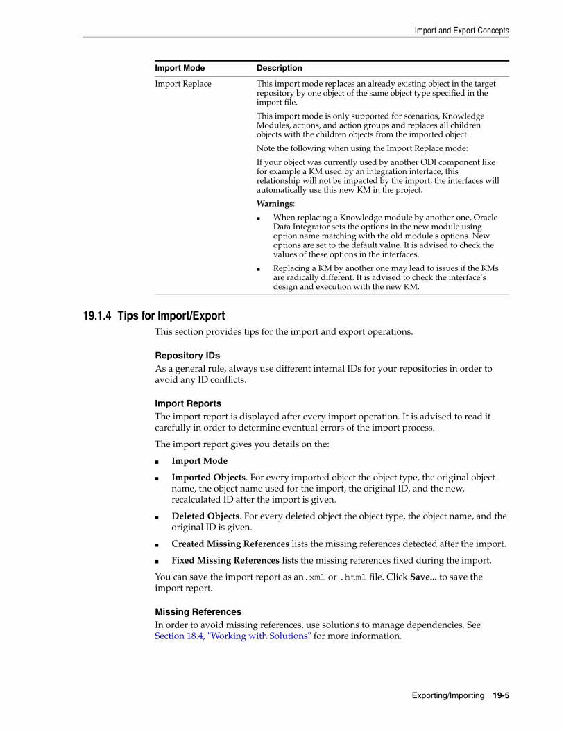
Import and Export Concepts
Exporting/Importing 19-5
19.1.4 Tips for Import/ExportThis section provides tips for the import and export operations.
Repository IDsAs a general rule, always use different internal IDs for your repositories in order to avoid any ID conflicts.
Import ReportsThe import report is displayed after every import operation. It is advised to read it carefully in order to determine eventual errors of the import process.
The import report gives you details on the:
■ Import Mode
■ Imported Objects. For every imported object the object type, the original object name, the object name used for the import, the original ID, and the new, recalculated ID after the import is given.
■ Deleted Objects. For every deleted object the object type, the object name, and the original ID is given.
■ Created Missing References lists the missing references detected after the import.
■ Fixed Missing References lists the missing references fixed during the import.
You can save the import report as an.xml or .html file. Click Save... to save the import report.
Missing ReferencesIn order to avoid missing references, use solutions to manage dependencies. See Section 18.4, "Working with Solutions" for more information.
Import Replace This import mode replaces an already existing object in the target repository by one object of the same object type specified in the import file.
This import mode is only supported for scenarios, Knowledge Modules, actions, and action groups and replaces all children objects with the children objects from the imported object.
Note the following when using the Import Replace mode:
If your object was currently used by another ODI component like for example a KM used by an integration interface, this relationship will not be impacted by the import, the interfaces will automatically use this new KM in the project.
Warnings:
■ When replacing a Knowledge module by another one, Oracle Data Integrator sets the options in the new module using option name matching with the old module's options. New options are set to the default value. It is advised to check the values of these options in the interfaces.
■ Replacing a KM by another one may lead to issues if the KMs are radically different. It is advised to check the interface’s design and execution with the new KM.
Import Mode Description
Exporting and Importing Objects
19-6 Oracle Fusion Middleware Developer's Guide for Oracle Data Integrator
Import ModeChoose the import mode carefully. See Section 19.1.3, "Import Modes" for more information.
19.2 Exporting and Importing ObjectsExporting and importing Oracle Data Integrator objects means transferring objects between different repositories.
When exporting an Oracle Data Integrator object, an XML export file is created. ODI objects have dependencies, as described in Section 19.1.2, "Relationships between Objects". These dependencies will be exported in the XML export file.
The content of this XML file will depend on the export method you will use:
■ Exporting an Object with its Child Components
■ Exporting an Object without its Child Components
The choice will depend on your goal, if you need to do a partial export then the Export Without Child Components is the one to use.
The Export Multiple ODI Objects feature is useful when you need to regularly export the same set of Objects.
Once the export has been performed, it is very important to choose the import strategy to suite your requirements.
Exporting an Object with its Child ComponentsThis option is the most common when you want to export an object. It allows you to export all subcomponents of the current object along with the object itself.
When an Object is exported with its child components, all container-dependent Objects – those which possess a direct parent/child relationship - are also exported. Referenced Objects are not exported.
For example, when you choose to export a Project with its child components, the export will contain the Project definition as well as all objects included in the Project, such as Folders, Interfaces, Procedures, Packages, Knowledge Modules, Variables, Sequences, Functions, etc. However, this export will not contain dependent objects referenced which are outside of the Project itself, such as Datastores and Columns, as defined previously in Section 19.1.2, "Relationships between Objects". Only the numeric ID references of these Objects will be exported.
Exporting an Object without its Child ComponentsThis option can be useful in some particular situations where you would want to take control of the import process. It allows you to export only the top-level definition of an object without any of its subobjects.
For example, if you choose to export a Model without its children, it will only contain the Model definition but not the underlying Sub-models and Datastores when you import this model to a new repository.
Partial Export/ImportIf you have a very large project that contains thousands of interfaces and you only want to export a subset of these to another work repository, you can either export the entire Project and then import it, or choose to do a partial manual export/import as follows:
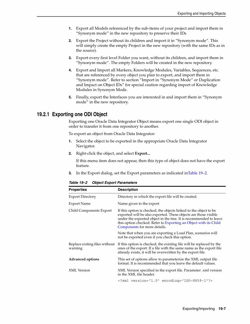
Exporting and Importing Objects
Exporting/Importing 19-7
1. Export all Models referenced by the sub-items of your project and import them in “Synonym mode” in the new repository to preserve their IDs
2. Export the Project without its children and import it in “Synonym mode”. This will simply create the empty Project in the new repository (with the same IDs as in the source).
3. Export every first level Folder you want, without its children, and import them in “Synonym mode”. The empty Folders will be created in the new repository.
4. Export and Import all Markers, Knowledge Modules, Variables, Sequences, etc. that are referenced by every object you plan to export, and import them in “Synonym mode”. Refer to section “Import in “Synonym Mode” or Duplication and Impact on Object IDs” for special caution regarding import of Knowledge Modules in Synonym Mode.
5. Finally, export the Interfaces you are interested in and import them in “Synonym mode” in the new repository.
19.2.1 Exporting one ODI ObjectExporting one Oracle Data Integrator Object means export one single ODI object in order to transfer it from one repository to another.
To export an object from Oracle Data Integrator:
1. Select the object to be exported in the appropriate Oracle Data Integrator Navigator.
2. Right-click the object, and select Export...
If this menu item does not appear, then this type of object does not have the export feature.
3. In the Export dialog, set the Export parameters as indicated inTable 19–2.
Table 19–2 Object Export Parameters
Properties Description
Export Directory Directory in which the export file will be created.
Export Name Name given to the export
Child Components Export If this option is checked, the objects linked to the object to be exported will be also exported. These objects are those visible under the exported object in the tree. It is recommended to leave this option checked. Refer to Exporting an Object with its Child Components for more details.
Note that when you are exporting a Load Plan, scenarios will not be exported even if you check this option.
Replace exiting files without warning
If this option is checked, the existing file will be replaced by the ones of the export. If a file with the same name as the export file already exists, it will be overwritten by the export file.
Advanced options This set of options allow to parameterize the XML output file format. It is recommended that you leave the default values.
XML Version XML Version specified in the export file. Parameter .xml version in the XML file header.
<?xml version="1.0" encoding="ISO-8859-1"?>
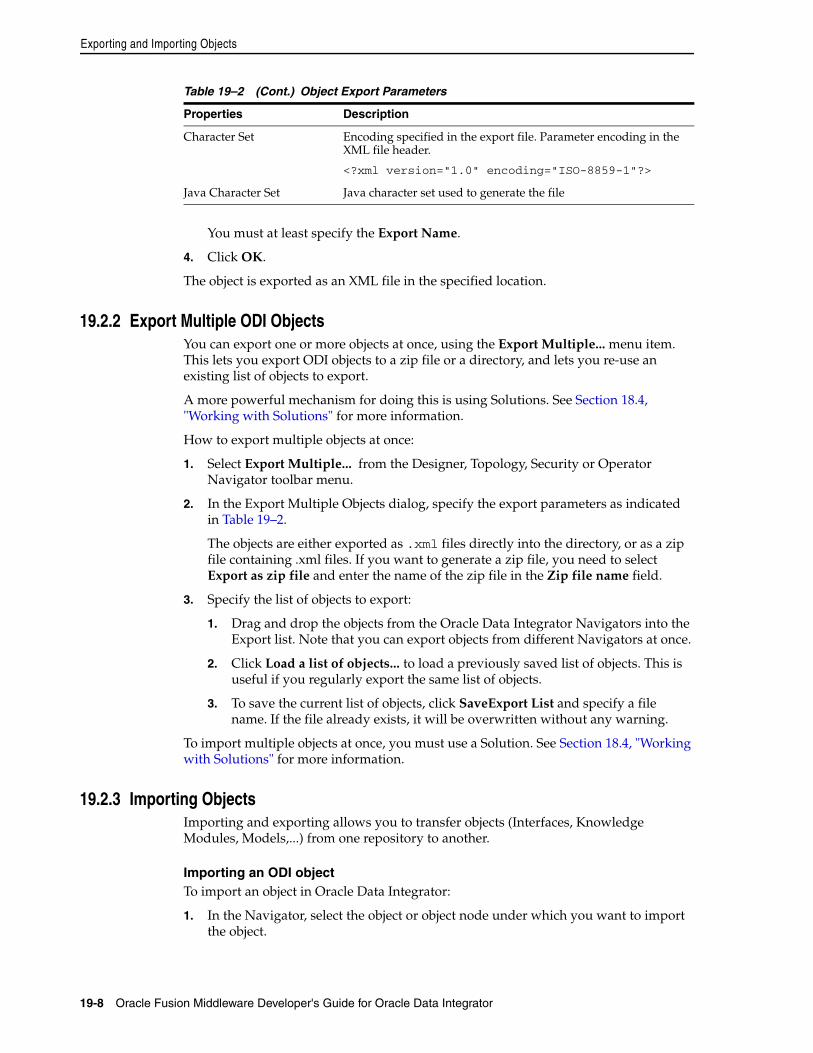
Exporting and Importing Objects
19-8 Oracle Fusion Middleware Developer's Guide for Oracle Data Integrator
You must at least specify the Export Name.
4. Click OK.
The object is exported as an XML file in the specified location.
19.2.2 Export Multiple ODI ObjectsYou can export one or more objects at once, using the Export Multiple... menu item. This lets you export ODI objects to a zip file or a directory, and lets you re-use an existing list of objects to export.
A more powerful mechanism for doing this is using Solutions. See Section 18.4, "Working with Solutions" for more information.
How to export multiple objects at once:
1. Select Export Multiple... from the Designer, Topology, Security or Operator Navigator toolbar menu.
2. In the Export Multiple Objects dialog, specify the export parameters as indicated in Table 19–2.
The objects are either exported as .xml files directly into the directory, or as a zip file containing .xml files. If you want to generate a zip file, you need to select Export as zip file and enter the name of the zip file in the Zip file name field.
3. Specify the list of objects to export:
1. Drag and drop the objects from the Oracle Data Integrator Navigators into the Export list. Note that you can export objects from different Navigators at once.
2. Click Load a list of objects... to load a previously saved list of objects. This is useful if you regularly export the same list of objects.
3. To save the current list of objects, click SaveExport List and specify a file name. If the file already exists, it will be overwritten without any warning.
To import multiple objects at once, you must use a Solution. See Section 18.4, "Working with Solutions" for more information.
19.2.3 Importing ObjectsImporting and exporting allows you to transfer objects (Interfaces, Knowledge Modules, Models,...) from one repository to another.
Importing an ODI objectTo import an object in Oracle Data Integrator:
1. In the Navigator, select the object or object node under which you want to import the object.
Character Set Encoding specified in the export file. Parameter encoding in the XML file header.
<?xml version="1.0" encoding="ISO-8859-1"?>
Java Character Set Java character set used to generate the file
Table 19–2 (Cont.) Object Export Parameters
Properties Description
Exporting and Importing Objects
Exporting/Importing 19-9
2. Right-click the object, and select Import, then the type of the object you wish to import.
3. In the Import dialog:
1. Select the Import Mode. Refer to Section 19.1.3, "Import Modes" for more information.
2. Enter the File Import Directory.
3. Select the file(s) to import from the list.
4. Click OK.
The XML-formatted files are imported into the work repository, and the imported objects appear in the Oracle Data Integrator Navigators.
Note that the parent or node under which objects are imported is dependent on the import mode used. When using DUPLICATION mode, the objects will be imported into where the Import option was selected. For Synonym imports, the objects will be imported under the parent specified by the objects parent id in the import file.
Importing a KMTo import a Knowledge Module into Oracle Data Integrator:
1. In Designer Navigator, select the project into which you want to import the KM.
2. Right-click the project, and select Import > Import Knowledge Modules....
3. In the Import dialog:
1. The Import Mode is set to Duplication. Refer to Section 19.1.3, "Import Modes" for more information.
2. Enter the File Import Directory.
3. Select the Knowledge Module file(s) to import from the list.
4. Click OK.
The Knowledge Modules are imported into the work repository and appear in your project under the Knowledge Modules node.
Importing a KM in Replace ModeKnowledge modules are usually imported into new projects in Duplication mode.
When you want to replace a KM in a project by another one and have all interfaces automatically use the new KM, you must use the Import Replace mode.To import a Knowledge Module in Replace mode:
1. Select the Knowledge Module you wish to replace.
2. Right-click the Knowledge Module and select Import Replace...
3. In the Replace Object dialog, specify the Knowledge Module export file.
4. Click OK.
The Knowledge Module is now replaced by the new one.
Repository-Level Export/Import
19-10 Oracle Fusion Middleware Developer's Guide for Oracle Data Integrator
19.3 Repository-Level Export/ImportAt repository level you can export and import the master repository and the work repositories.
19.3.1 Exporting and Importing the Master RepositoryThe master repository export/import procedure allows you to transfer the whole repository (Topology and Security domains included) from one repository to another.
It can be performed in Topology Navigator, to import the exported objects in an existing repository, or while creating a new master repository.
Exporting the Master Repository in Topology NavigatorThe objects that are exported when exporting the master repository are objects, methods, profiles, users, languages, versions (if option selected), solutions (if option selected), open tools, password policies, entities, links, fields, lookups, technologies, datatypes, datatypes conversions, logical agents, contexts and the child objects.
To export a master repository:
1. From the Topology Navigator toolbar menu select Export > Master Repository...
2. In the Export dialog, set the Export parameters as indicated inTable 19–2.
The master repository and its topology and security settings are either exported as .xml files directly into the directory, or as a zip file containing .xml files. If you want to generate a zip file, you need to select Export to zip file and enter the name of the zip file in the Zip File Name field.
3. Select Export versions, if you want to export all stored versions of objects that are stored in the repository. You may wish to unselect this option in order to reduce the size of the exported repository, and to avoid transferring irrelevant project work.
4. Select Export solutions, if you want to export all stored solutions that are stored in the repository. You may wish to unselect this option for similar reasons.
5. Click OK.
The export files are created in the specified export directory.
Importing the Master RepositoryTo import the exported master repository objects into an existing master repository:
1. From the Topology Navigator toolbar menu select Import > Master Repository...
2. In the Import dialog:
WARNING: Replacing a Knowledge module by another one in Oracle Data Integrator sets the options in the new module using the option name similarities with the old module's options. New options are set to the default value.
It is advised to check the values of these options in the interfaces as well as the interfaces' design and execution with the new KM.
Refer to the Import Replace mode description in the Section 19.1.3, "Import Modes" for more information.
Repository-Level Export/Import
Exporting/Importing 19-11
1. Select the Import Mode. Refer to Section 19.1.3, "Import Modes" for more information.
2. Select whether you want to import the files From a Folder or From a ZIP file.
3. Enter the file import folder or zip file.
3. Click OK.
The master repository contains now the objects you have imported.
Creating a new Master Repository using a previous Master exportTo create a new master repository using an export of another master repository:
1. Open the New Gallery by choosing File > New.
2. In the New Gallery, in the Categories tree, select ODI.
3. Select from the Items list the Master Repository Import Wizard.
4. Click OK.
The Master Repository Import Wizard appears.
5. Specify the Database Connection parameters as follows:
■ Login: User ID/login of the owner of the tables you have created for the master repository
■ JDBC Driver: The driver used to access the technology, which will host the repository.
■ JDBC URL: The complete path for the data server to host the repository.
Note that the parameters JDBC Driver and URL are synchronized and the default values are technology dependant.
■ User: The user id/login of the owner of the tables.
■ Password: This user's password.
■ DBA User: The database administrator’s username
■ DBA Password: This user’s password
6. Specify the Repository Configuration parameters as follows:
■ ID: A specific ID for the new master repository, rather than the default 0. This will affect imports and exports between repositories.
■ Use a Zip File: If using a compressed export file, check the Use a Zip File box and select in the Export Zip File field the file containing your master repository export.
■ Export Path: If using an uncompressed export, select the directory containing the export in the Export Path field.
■ Technology: From the list, select the technology your repository will be based on.
7. Click Test Connection to test the connection to your master repository.
WARNING: All master repositories should have distinct identifiers. Check that the identifier you are choosing is not the identifier of an existing repository
Repository-Level Export/Import
19-12 Oracle Fusion Middleware Developer's Guide for Oracle Data Integrator
The Information dialog opens and informs you whether the connection has been established.
8. Click Next.
9. Specify the password storage details:
■ Select Use Password Storage Configuration specified in Export if you want to use the configuration defined in the export.
■ Select Use New Password Storage Configuration if you do not want to use the configuration defined in the export and select
– Internal Password Storage if you want to store passwords in the Oracle Data Integrator repository
– External Password Storage if you want use JPS Credential Store Framework (CSF) to store the data server and context passwords. Indicate the MBean Server Parameters to access the credential store as described in Table 23–2.
Refer to the Section 23.3.1, "Setting Up External Password Storage" for more information on password storage details.
10. In the Master Repository Import Wizard click Finish to validate your entries.
A new repository is created and the exported components are imported in this master repository.
19.3.2 Export/Import the Topology and Security SettingsExporting then importing the topology or security allows you to transfer a domain from one master repository to another.
Exporting the Topology and Security SettingsThe domains that can be exported are given below:
■ Topology: the full topology (logical and physical architectures including the local repository, data servers, hosts, agents, generic actions, technologies, datatypes, logical schemas, and contexts).
■ Logical Topology: technologies (connection, datatype or language information), logical agents, logical schemas, actions and action groups.
■ Security: objects, methods, users, profiles, privileges, password policies and hosts.
■ Execution Environment: technologies, data servers, contexts, generic actions, load balanced agents, physical schemas and agents.
To export the topology/security:
1. From the Topology or Security Navigator toolbar menu select Export and then one of the following options:
■ Topology...
■ Logical Topology...
■ Security Settings...
■ Execution Environment...
2. In the Export dialog, specify the export parameters as indicated in Table 19–2.
Repository-Level Export/Import
Exporting/Importing 19-13
The topology and security settings are either exported as .xml files directly into the directory, or as a zip file containing .xml files. If you want to generate a zip file, you need to select Export to zip file and enter the name of the zip file in the Zip File Name field.
3. Click OK.
The export files are created in the specified export directory.
Importing the TopologyTo import a topology export:
1. From the Topology Navigator toolbar menu select Import and then one of the following options:
■ Topology...
Logical Topology...
Execution environment...
2. In the Import dialog:
1. Select the Import Mode. Refer to Section 19.1.3, "Import Modes" for more information.
2. Select whether to import the topology export from a Folder or a Zip File.
3. Enter the file import directory.
3. Click OK.
The specified files are imported into the master repository.
Importing the Security SettingsTo import a Security export:
1. From the Security Navigator toolbar menu select Import > Security Settings...
2. In the Import dialog:
1. Select the Import Mode. Refer to Section 19.1.3, "Import Modes" for more information.
2. Select whether to import the security export from a Folder or a Zip File.
3. Enter the file import directory.
3. Click OK.
The specified files are imported into the master repository.
19.3.3 Exporting and Importing a Work RepositoryImporting or exporting a work repository allows you to transfer all work repository objects from one repository to another.
Exporting a Work RepositoryTo export a work repository:
1. From the Designer Navigator toolbar menu select Export > Work Repository...
2. In the Export dialog, set the Export parameters as indicated inTable 19–2.
Exporting the Technical Environment
19-14 Oracle Fusion Middleware Developer's Guide for Oracle Data Integrator
The work repository with its models and projects are either exported as .xml files directly into the directory, or as a zip file containing .xml files. If you want to generate a zip file, you need to select Export to zip file and enter the name of the zip file in the Zip File Name field
3. Click OK.
The export files are created in the specified export directory.
Importing a Work RepositoryTo import a work repository:
1. From the Designer Navigator toolbar menu select Import > Work Repository...
2. In the Import dialog:
1. Select the Import mode. Refer to Section 19.1.3, "Import Modes" for more information.
2. Select whether to import the work repository from a Folder or a Zip File.
3. Enter the file import directory.
3. Click OK.
The specified files are imported into the work repository.
19.4 Exporting the Technical EnvironmentThis feature produces a comma separated (.csv) file in the directory of your choice, containing the details of the technical environment. This information is useful for support purposes.
You can customize the format of this file.
To produce the technical environment file:
1. From the Topology Navigator toolbar menu select Export >Technical Environment...
2. In the Technical environment dialog, specify the export parameters as indicated in Table 19–3:
Table 19–3 Technical Environment Export Parameters
Properties Description
Export Directory Directory in which the export file will be created.
File Name Name of the .cvs export file
Advanced options This set of options allow to parameterize the XML output file format. It is recommended that you leave the default values.
Character Set Encoding specified in the export file. Parameter encoding in the XML file header.
<?xml version="1.0" encoding="ISO-8859-1"?>
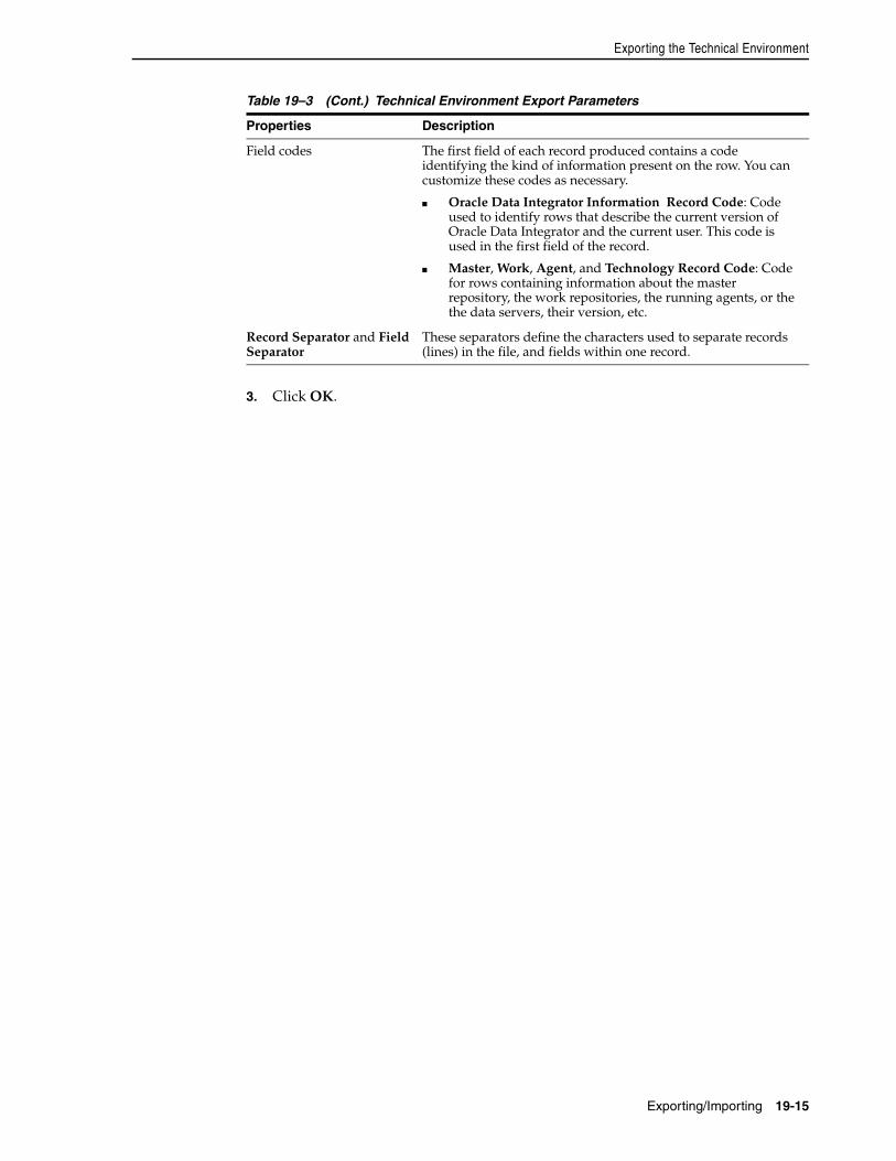
Exporting the Technical Environment
Exporting/Importing 19-15
3. Click OK.
Field codes The first field of each record produced contains a code identifying the kind of information present on the row. You can customize these codes as necessary.
■ Oracle Data Integrator Information Record Code: Code used to identify rows that describe the current version of Oracle Data Integrator and the current user. This code is used in the first field of the record.
■ Master, Work, Agent, and Technology Record Code: Code for rows containing information about the master repository, the work repositories, the running agents, or the the data servers, their version, etc.
Record Separator and Field Separator
These separators define the characters used to separate records (lines) in the file, and fields within one record.
Table 19–3 (Cont.) Technical Environment Export Parameters
Properties Description

Exporting the Technical Environment
19-16 Oracle Fusion Middleware Developer's Guide for Oracle Data Integrator
Part VIPart VI Running and Monitoring Integration
Processes
This part describes how to run and monitor integration processes.
This part contains the following chapters:
■ Chapter 20, "Running Integration Processes"
■ Chapter 21, "Monitoring Integration Processes"
■ Chapter 22, "Working with Oracle Data Integrator Console"

20
Running Integration Processes 20-1
20Running Integration Processes
This chapter describes how to run and schedule integration processes.
This chapter includes the following sections:
■ Section 20.1, "Understanding ODI Executions"
■ Section 20.2, "Executing Interfaces, Procedures, Packages and Model Operations"
■ Section 20.3, "Executing a Scenario"
■ Section 20.4, "Restarting a Session"
■ Section 20.5, "Stopping a Session"
■ Section 20.6, "Executing a Load Plan"
■ Section 20.7, "Restarting a Load Plan Run"
■ Section 20.8, "Stopping a Load Plan Run"
■ Section 20.9, "Scheduling Scenarios and Load Plans"
■ Section 20.10, "Simulating an Execution"
■ Section 20.11, "Managing Executions Using Web Services"
20.1 Understanding ODI ExecutionsAn execution takes place when an integration task needs to be performed by Oracle Data Integrator. This integration task may be one of the following:
■ An operation on a model, sub-model or a datastore, such as a customized reverse-engineering, a journalizing operation or a static check started from the Oracle Data Integrator Studio
■ The execution of a design-time object, such as an interface, a package or a procedure, typically started from the Oracle Data Integrator Studio
■ The execution of a run-time scenario or a Load Plan that was launched from the Oracle Data Integrator Studio, from a command line, via a schedule or a web service interface
Oracle Data Integrator generates the code for an execution in the form of a session or in the from of a Load Plan run if a Load Plan is executed.
A run-time Agent processes this code and connects to the sources and targets to perform the data integration. These sources and targets are located by the Agent using a given execution context.
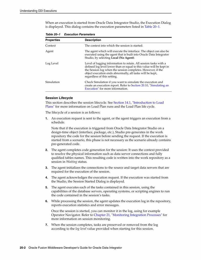
Understanding ODI Executions
20-2 Oracle Fusion Middleware Developer's Guide for Oracle Data Integrator
When an execution is started from Oracle Data Integrator Studio, the Execution Dialog is displayed. This dialog contains the execution parameters listed in Table 20–1.
Session LifecycleThis section describes the session lifecycle. See Section 14.1, "Introduction to Load Plans" for more information on Load Plan runs and the Load Plan life cycle.
The lifecycle of a session is as follows:
1. An execution request is sent to the agent, or the agent triggers an execution from a schedule.
Note that if the execution is triggered from Oracle Data Integrator Studio on a design-time object (interface, package, etc.), Studio pre-generates in the work repository the code for the session before sending the request. If the execution is started from a scenario, this phase is not necessary as the scenario already contains pre-generated code.
2. The agent completes code generation for the session: It uses the context provided to resolve the physical information such as data server connections and fully qualified tables names. This resulting code is written into the work repository as a session in Waiting status.
3. The agent initializes the connections to the source and target data servers that are required for the execution of the session.
4. The agent acknowledges the execution request. If the execution was started from the Studio, the Session Started Dialog is displayed.
5. The agent executes each of the tasks contained in this session, using the capabilities of the database servers, operating systems, or scripting engines to run the code contained in the session’s tasks.
6. While processing the session, the agent updates the execution log in the repository, reports execution statistics and error messages.
Once the session is started, you can monitor it in the log, using for example Operator Navigator. Refer to Chapter 21, "Monitoring Integration Processes" for more information on session monitoring.
7. When the session completes, tasks are preserved or removed from the log according to the log level value provided when starting for this session.
Table 20–1 Execution Parameters
Properties Description
Context The context into which the session is started.
Agent The agent which will execute the interface. The object can also be executed using the agent that is built into Oracle Data Integrator Studio, by selecting Local (No Agent).
Log Level Level of logging information to retain. All session tasks with a defined log level lower than or equal to this value will be kept in the Session log when the session completes. However, if the object execution ends abnormally, all tasks will be kept, regardless of this setting.
Simulation Check Simulation if you want to simulate the execution and create an execution report. Refer to Section 20.10, "Simulating an Execution" for more information.
Executing a Scenario
Running Integration Processes 20-3
When starting an execution from other locations such as a command line or a web service, you provide similar execution parameters, and receive a similar Session Started feedback. If the session is started synchronously from a command line or web service interface, the command line or web service will wait until the session completes, and provide the session return code and an error message, if any.
20.2 Executing Interfaces, Procedures, Packages and Model OperationsInterfaces, procedures, and packages are design-time objects that can be executed from the Designer Navigator of Oracle Data Integrator Studio:
■ For more information on interfaces execution, refer to Section 11.3.8, "Execute the Integration Interface".
■ For more information on procedures execution, refer to Section 12.1.3, "Using Procedures".
■ For more information on packages execution, refer to Section 10.5, "Running the Package".
■ For more information on model operations, refer to Section 5.2, "Creating and Reverse-Engineering a Model", Section 5.6, "Checking Data Quality in a Model" and Section 7.2, "Setting up Journalizing".
20.3 Executing a ScenarioScenarios can be executed in several ways:
■ "Executing a Scenario from ODI Studio"
■ "Executing a Scenario from a Command Line".
■ From a Web Service. See Section 20.11.2, "Executing a Scenario Using a Web Service" for more information.
■ From ODI Console. See Section 22.2.3, "Managing Scenarios and Sessions".
20.3.1 Executing a Scenario from ODI StudioYou can start a scenario from Oracle Data Integrator Studio from Designer or Operator Navigator.
To start a scenario from Oracle Data Integrator Studio:
1. Select the scenario in the Projects accordion (in Designer Navigator) or the Scenarios accordion (in Operator Navigator).
2. Right-click, then select Execute.
Note: A Session is always identified by a unique Session Number (or Session ID). This number can be viewed when monitoring the session, and is also returned by the command line or web service interfaces when starting a session.
Note: Before running a scenario, you need to have the scenario generated from Designer Navigator or imported from a file. Refer to Chapter 13, "Working with Scenarios" for more information.
Executing a Scenario
20-4 Oracle Fusion Middleware Developer's Guide for Oracle Data Integrator
3. In the Execution dialog, set the execution parameters. Refer to Table 20–1 for more information. To execute the scenario with the agent that is built into Oracle Data Integrator Studio, select Local (No Agent).
4. Click OK.
5. If the scenario uses variables as parameters, the Variable values dialog is displayed. Select the values for the session variables. Selecting Latest value for a variable uses its current value, or default value if none is available.
When the agent has started to process the session, the Session Started dialog appears.
20.3.2 Executing a Scenario from a Command LineYou can start a scenario from a command line.
Before executing a scenario from a command line, read carefully the following requirements:
■ The command line scripts, which are required for performing the tasks described in this section, are only available if you have installed the Oracle Data Integrator Standalone Agent. See the Oracle Fusion Middleware Installation Guide for Oracle Data Integrator for information about how to install the Standalone Agent.
■ To use this command the connection to your repository must be configured in the odiparams file. See Chapter 4.3, "Managing Agents" for more information.
■ When starting a scenario from a command line, the session is not started by default against a remote run-time agent, but is executed by a local Java process started from the command line. This process can be aborted locally, but cannot receive a session stop signal as it is not a real run-time agent. As a consequence, sessions started this way cannot be stopped remotely.
This process will be identified in the Data Integrator log after the Local Agent name. You can change this name using the NAME parameter.
If you want to start the session against a run-time agent, you must use the AGENT_URL parameter.
To start a scenario from a command line:
1. Change directory to the /agent/bin directory of the Oracle Data Integrator installation.
2. Enter the following command to start a scenario.
On UNIX systems:
./startscen.sh <scenario_name> <scenario_version> <context_code> [<log_level>] [-AGENT_URL=<remote_agent_url>] [-NAME=<local_agent_name>] [-SESSION_NAME=<session_name>] [-KEYWORDS=<keywords>] [<variable>=<value>]*
On Windows systems:
startscen.bat <scenario_name> <scenario_version> <context_code> [<log_level>] [-AGENT_URL=<remote_agent_url>] ["-NAME=<local_agent_name>"] ["-SESSION_NAME=<session_name>"] ["-KEYWORDS=<keywords>"] ["<variable>=<value>"]*
Executing a Scenario
Running Integration Processes 20-5
Table 20–2 lists the different parameters, both mandatory and optional. The parameters are preceded by the "-" character and the possible values are preceded by the "=" character. You must follow the character protection syntax specific to the operating system on which you enter the command.
Note: On Windows platforms, it is necessary to "delimit" the command arguments containing "=" signs or spaces, by using double quotes. The command call may differ from the Unix command call. For example:
On Unix
./startscen.sh DWH 001 GLOBAL SESSION_NAME=MICHIGAN
On Windows
startscen.bat DWH 001 GLOBAL "SESSION_NAME=MICHIGAN"
Table 20–2 Startscen command Parameters
Parameters Description
<scenario_name> Name of the scenario (mandatory).
<scenario_version> Version of the scenario (mandatory). If the version specified is -1, the latest version of the scenario is executed.
<context_code> Code of the execution context (mandatory).
<log_level> Level of logging information to retain.
This parameter is in the format LEVEL<n> where <n> is the expected logging level, between 0 and 5. The default log level is 5.
Example: startscen.bat SCENAR 1 GLOBAL LEVEL5
-AGENT_URL=<remote_agent_url>
URL of the run-time agent that will run this session. If this parameter is set, then NAME parameter is ignored.
-NAME=<local_agent_name>
Agent name that will appear in the execution log for this session, instead of Local Agent. This parameter is ignored if AGENT_URL is used.
Note that Using an existing physical agent name in the NAME parameter is not recommended. The run-time agent which name is used does not have all the information about this session and will not be able to manage it correctly. The following features will not work correctly for this session:
■ Clean stale session: This session will be considered as stale by this agent if this agent is started. The session will be pushed to error when the agent will detect this session
■ .Kill Sessions: This agent cannot kill the session when requested.
■ Agent Session Count: This session is counted in this agent's sessions, even if it is not executed by it.
It is recommended to use a NAME that does not match any existing physical agent name.
If you want to start a session on a given physical agent, you must use the AGENT_URL parameter instead.
-SESSION_NAME=<session_name>
Name of the session that will appear in the execution log.
Restarting a Session
20-6 Oracle Fusion Middleware Developer's Guide for Oracle Data Integrator
20.4 Restarting a SessionAny session that has encountered an error, or has been stopped by the user can be restarted.
Oracle Data Integrator uses JDBC transactions when interacting with source and target data servers, and any open transaction state is not persisted when a session finishes in error state. The appropriate restart point is the task that started the unfinished transaction(s). If such a restart point is not identifiable, it is recommended that you start a fresh session by executing the scenario instead of restarting existing sessions that are in error state.
Only sessions in status Error or Waiting can be restarted. By default, a session restarts from the last task that failed to execute (typically a task in error or in waiting state). A session may need to be restarted in order to proceed with existing staging tables and avoid re-running long loading phases. In that case the user should take into consideration transaction management, which is KM specific. A general guideline is: If a crash occurs during a loading task, you can restart from the loading task that failed. If a crash occurs during an integration phase, restart from the first integration task, because integration into the target is within a transaction. This guideline applies only to one interface at a time. If several interfaces are chained and only the last one performs the commit, then they should all be restarted because the transaction runs over several interfaces.
To restart from a specific task or step:
1. In Operator Navigator, navigate to this task or step, edit it and switch it to Waiting state.
2. Set all tasks and steps after this one in the Operator tree view to Waiting state.
3. Restart the session using one of the following methods:
■ Restarting a Session from ODI Studio
■ Restarting a Session from a Command Line.
■ From a Web Service. See Section 20.11.4, "Restarting a Session Using a Web Service" for more information.
■ From ODI Console. See Section 22.2.3, "Managing Scenarios and Sessions".
-KEYWORDS=<keywords> List of keywords attached to this session. These keywords make session identification easier. The list is a comma-separated list of keywords.
<variable>=<value> Allows to assign a <value> to a <variable> for the execution of the scenario. <variable> is either a project or global variable. Project variables should be named <Project Code>.<Variable Name>. Global variables should be called GLOBAL.<variable Name>.
This parameter can be repeated to assign several variables.
Do not use a hash sign (#) to prefix the variable name on the startscen command line.
Table 20–2 (Cont.) Startscen command Parameters
Parameters Description
Restarting a Session
Running Integration Processes 20-7
20.4.1 Restarting a Session from ODI StudioTo restart a session from Oracle Data Integrator Studio:
1. In Operator Navigator, select the session that you want to restart.
2. Right-click and select Restart.
3. In the Choose Restart Mode dialog, select the agent you want to use for running the new session.
4. Click OK.
When Oracle Data Integrator has restarted the session, the Session Started dialog appears.
20.4.2 Restarting a Session from a Command LineBefore restarting a session from a command line, read carefully the following requirements:
■ The command line scripts, which are required for performing the tasks described in this section, are only available if you have installed the Oracle Data Integrator Standalone Agent. See the Oracle Fusion Middleware Installation Guide for Oracle Data Integrator for information about how to install the Standalone Agent.
■ To use this command the connection to your repository must be configured in the odiparams file. See Chapter 4.3, "Managing Agents" for more information.
■ When restarting a session from a command line, the session is not started by default against a remote run-time agent, but is executed by a local Java process started from the command line. This process can be aborted locally, but cannot receive a session stop signal as it is not a real run-time agent. As a consequence, sessions started this way cannot be stopped remotely.
If you want to start the session against a run-time agent, you must use the AGENT_URL parameter.
To restart a session from a command line:
1. Change directory to the /agent/bin directory of the Oracle Data Integrator installation.
2. Enter the following command to start a scenario.
On UNIX systems:
./restartsession.sh <session_number> [-AGENT_URL=<remote_agent_url>]
On Windows systems:
restartsession.bat <session_number> ["-AGENT_URL=<remote_agent_url>"]
WARNING: When restarting a session, all connections and transactions to the source and target systems are re-created, and not recovered from the previous session run. As a consequence, uncommitted operations on transactions from the previous run are not applied, and data required for successfully continuing the session may not be present.

Stopping a Session
20-8 Oracle Fusion Middleware Developer's Guide for Oracle Data Integrator
Table 20–3 lists the different parameters of this command, both mandatory and optional. The parameters are preceded by the "-" character and the possible values are preceded by the "=" character. You must follow the character protection syntax specific to the operating system on which you enter the command.
20.5 Stopping a SessionAny running or waiting session can be stopped. You may want to stop a session when you realize that for example your interface contains errors or when the execution takes a long time.
Note that there are two ways to stop a session:
■ Normal: The session is stopped once the current task is finished.
■ Immediate: The current task is immediately interrupted and the session is stopped. This mode allows to stop long-running tasks, as for example long SQL statements before they complete.
Session can be stopped in several ways:
■ Stopping a Session From ODI Studio
Table 20–3 restartsess command Parameters
Parameters Description
<session_number> Number (ID) of the session to be restarted.
-AGENT_URL=<remote_agent_url>
URL of the run-time agent that will restart this session. By default the session is executed by a local Java process started from the command line.
Note: To use this command the connection to your repository must be configured in the odiparams file. See Section 4.3, "Managing Agents" for more information.
Note: When restarting a session from a command line, the session is not started by default against a remote run-time agent, but is executed by a local Java process started from the command line.
If you want to start the session against a run-time agent, you must use the AGENT_URL parameter.
Note: The immediate stop works only with technologies and drivers that support task interruption. It is supported if the statement.cancel method is implemented in the JDBC driver.
Note: Only sessions that are running within a Java EE or standalone Agent can be stopped. Sessions running in the Studio built-in Agent or started with the startscen.sh or startscen.bat script without the AGENT_URL parameter, cannot be stopped. See Section 20.3, "Executing a Scenario" for more information.
Stopping a Session
Running Integration Processes 20-9
■ Stopping a Session From a Command Line.
■ From ODI Console. See Section 22.2.3, "Managing Scenarios and Sessions".
20.5.1 Stopping a Session From ODI StudioTo stop a session from Oracle Data Integrator Studio:
1. In Operator Navigator, select the running or waiting session to stop from the tree.
2. Right-click then select Stop Normal or Stop Immediate.
3. In the Stop Session Dialog, click OK.
The session is stopped and changed to Error status.
20.5.2 Stopping a Session From a Command LineBefore stopping a session from a command line, read carefully the following requirements:
■ The command line scripts, which are required for performing the tasks described in this section, are only available if you have installed the Oracle Data Integrator Standalone Agent. See the Oracle Fusion Middleware Installation Guide for Oracle Data Integrator for information about how to install the Standalone Agent.
■ To use this command the connection to your repository must be configured in the odiparams file. See Chapter 4.3, "Managing Agents" for more information.
To stop a session from a command line:
1. Change directory to the /agent/bin directory of the Oracle Data Integrator installation.
2. Enter the following command to start a scenario.
On UNIX systems:
./stopsession.sh <session_id> [-AGENT_URL=<remote_agent_url>] [-STOP_LEVEL=<normal (default) | immediate>]
On Windows systems:
stopsession.bat <session_id> ["-AGENT_URL=<remote_agent_url>"]["-STOP_LEVEL=<normal (default) | immediate>"]
Table 20–3 lists the different parameters of this command, both mandatory and optional. The parameters are preceded by the "-" character and the possible values are preceded by the "=" character. You must follow the character protection syntax specific to the operating system on which you enter the command.
Table 20–4 StopSession command Parameters
Parameters Description
<session_id> Number (ID) of the session to be restarted.
-AGENT_URL=<remote_agent_url>
URL of the run-time agent that stops this session. By default the session is executed by a local Java process started from the command line.
[-STOP_LEVEL=<normal (default) | immediate>]
The level used to stop a running session. If it is omitted, normal will be used as the default stop level.
Executing a Load Plan
20-10 Oracle Fusion Middleware Developer's Guide for Oracle Data Integrator
20.6 Executing a Load PlanLoad Plans can be executed in several ways:
■ Executing a Load Plan from ODI Studio
■ Executing a Load Plan from a Command Line
■ From a Web Service. See Section 20.11.5, "Executing a Load Plan Using a Web Service" for more information.
■ From ODI Console. See Section 22.2.4, "Managing Load Plans".
20.6.1 Executing a Load Plan from ODI StudioIn ODI Studio, you can run a Load Plan in Designer Navigator or in Operator Navigator.
To run a Load Plan in Designer Navigator or Operator Navigator:
1. In the Load Plans and Scenarios accordion, select the Load Plan you want to execute.
2. Right-click and select Execute.
3. In the Start Load Plan dialog, select the execution parameters:
■ Select the Context into which the Load Plan will be executed.
■ Select the Logical Agent that will run the step.
■ In the Variables table, enter the Startup values for the variables used in this Load Plan.
4. Click OK.
5. The Load Plan Started Window appears.
6. Click OK.
A new execution of the Load Plan is started: a Load Plan instance is created and also the first Load Plan run. You can review the Load Plan execution in the Operator Navigator.
20.6.2 Executing a Load Plan from a Command LineYou can start a Load Plan from a command line.
Before executing a Load Plan from a command line, read carefully the following requirements:
■ The command line scripts, which are required for performing the tasks described in this section, are only available if you have installed the Oracle Data Integrator Standalone Agent. See the Oracle Fusion Middleware Installation Guide for Oracle Data Integrator for information about how to install the Standalone Agent.
Note: To use this command the connection to your repository must be configured in the odiparams file. See Section 4.3, "Managing Agents" for more information.
Note: A Load Plan cannot be executed using the ODI Studio built-in agent called Local (No Agent).
Executing a Load Plan
Running Integration Processes 20-11
■ To use this command, the connection to your repository must be configured in the odiparams file. See Chapter 4.3, "Managing Agents" for more information.
■ A Load Plan Run is started against a run-time agent identified by the AGENT_URL parameter.
To start a Load Plan from a command line:
1. Change directory to /agent/bin directory of the Oracle Data Integrator installation.
2. Enter the following command to start a Load Plan.
On UNIX systems:
./startloadplan.sh <load_plan_name> <context_code> -AGENT_URL=<agent_url> [-KEYWORDS=<keywords>] [<variable>=<value>]*
On WINDOWS systems:
startloadplan.bat <load_plan_name> <context_code> "-AGENT_URL=<agent_url>" ["-KEYWORDS=<keywords>"] ["<variable>=<value>"]*
Table 20–5 lists the different parameters, both mandatory and optional. The parameters are preceded by the "-" character and the possible values are preceded by the "=" character. You must follow the character protection syntax specific to the operating system on which you enter the command.
Note: On Windows platforms, it is necessary to "delimit" the command arguments containing "=" signs or spaces, by using double quotes. The command call may differ from the Unix command call. For example:
On UNIX systems:
./startloadplan.sh DWLoadPlan DEV -AGENT_URL=http://localhost:20910/oraclediagent
On WINDOWS systems:
startloadplan.bat DWLoadPlan DEV "-AGENT_URL=http://localhost:20910/oraclediagent"
Table 20–5 Startloadplan Command Parameters
Parameters Description
<load_plan_name> Name of the Load Plan to be started (mandatory)
<context_code> Code of the context used for starting the Load Plan. Note that if this value is not provided, the Load Plan uses the context of the session that calls it (mandatory)
"-AGENT_URL=<agent_url>"
URL of the Physical Agent that starts the Load Plan (mandatory)
["-KEYWORDS=<Keywords>"]
Keywords to improve the organization of ODI logs by session folders and automatic classification. Enter a comma separated list of keywords that will be attached to this Load Plan.
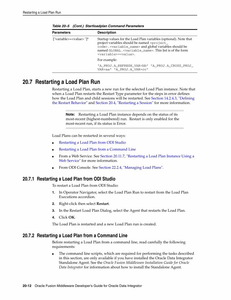
Restarting a Load Plan Run
20-12 Oracle Fusion Middleware Developer's Guide for Oracle Data Integrator
20.7 Restarting a Load Plan RunRestarting a Load Plan, starts a new run for the selected Load Plan instance. Note that when a Load Plan restarts the Restart Type parameter for the steps in error defines how the Load Plan and child sessions will be restarted. See Section 14.2.4.3, "Defining the Restart Behavior" and Section 20.4, "Restarting a Session" for more information.
Load Plans can be restarted in several ways:
■ Restarting a Load Plan from ODI Studio
■ Restarting a Load Plan from a Command Line
■ From a Web Service. See Section 20.11.7, "Restarting a Load Plan Instance Using a Web Service" for more information.
■ From ODI Console. See Section 22.2.4, "Managing Load Plans".
20.7.1 Restarting a Load Plan from ODI StudioTo restart a Load Plan from ODI Studio:
1. In Operator Navigator, select the Load Plan Run to restart from the Load Plan Executions accordion.
2. Right-click then select Restart.
3. In the Restart Load Plan Dialog, select the Agent that restarts the Load Plan.
4. Click OK.
The Load Plan is restarted and a new Load Plan run is created.
20.7.2 Restarting a Load Plan from a Command LineBefore restarting a Load Plan from a command line, read carefully the following requirements:
■ The command line scripts, which are required for performing the tasks described in this section, are only available if you have installed the Oracle Data Integrator Standalone Agent. See the Oracle Fusion Middleware Installation Guide for Oracle Data Integrator for information about how to install the Standalone Agent.
["variable>=<value> "]* Startup values for the Load Plan variables (optional). Note that project variables should be named <project_code>.<variable_name> and global variables should be named GLOBAL.<variable_name>. This list is of the form <variable>=<value>.
For example:
"A_PROJ.A_REFRESH_VAR=bb" "A_PROJ.A_CROSS_PROJ_VAR=aa" "A_PROJ.A_VAR=cc"
Note: Restarting a Load Plan instance depends on the status of its most-recent (highest-numbered) run. Restart is only enabled for the most-recent run, if its status is Error.
Table 20–5 (Cont.) Startloadplan Command Parameters
Parameters Description
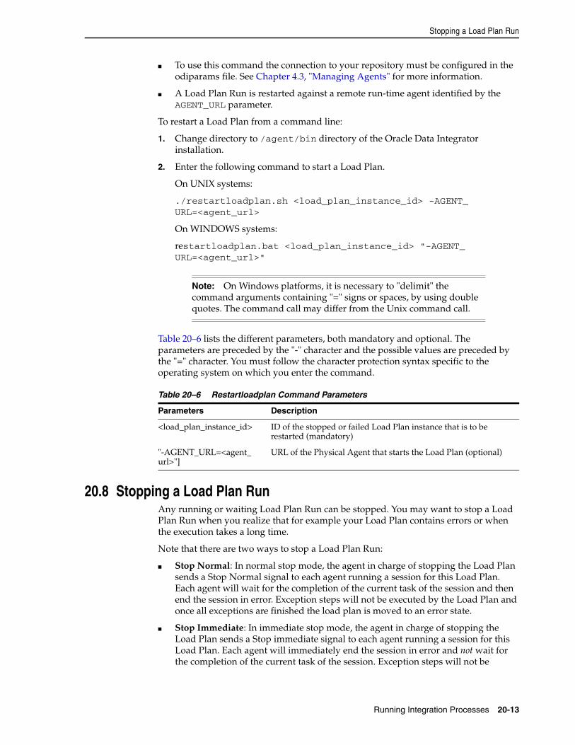
Stopping a Load Plan Run
Running Integration Processes 20-13
■ To use this command the connection to your repository must be configured in the odiparams file. See Chapter 4.3, "Managing Agents" for more information.
■ A Load Plan Run is restarted against a remote run-time agent identified by the AGENT_URL parameter.
To restart a Load Plan from a command line:
1. Change directory to /agent/bin directory of the Oracle Data Integrator installation.
2. Enter the following command to start a Load Plan.
On UNIX systems:
./restartloadplan.sh <load_plan_instance_id> -AGENT_URL=<agent_url>
On WINDOWS systems:
restartloadplan.bat <load_plan_instance_id> "-AGENT_URL=<agent_url>"
Table 20–6 lists the different parameters, both mandatory and optional. The parameters are preceded by the "-" character and the possible values are preceded by the "=" character. You must follow the character protection syntax specific to the operating system on which you enter the command.
20.8 Stopping a Load Plan RunAny running or waiting Load Plan Run can be stopped. You may want to stop a Load Plan Run when you realize that for example your Load Plan contains errors or when the execution takes a long time.
Note that there are two ways to stop a Load Plan Run:
■ Stop Normal: In normal stop mode, the agent in charge of stopping the Load Plan sends a Stop Normal signal to each agent running a session for this Load Plan. Each agent will wait for the completion of the current task of the session and then end the session in error. Exception steps will not be executed by the Load Plan and once all exceptions are finished the load plan is moved to an error state.
■ Stop Immediate: In immediate stop mode, the agent in charge of stopping the Load Plan sends a Stop immediate signal to each agent running a session for this Load Plan. Each agent will immediately end the session in error and not wait for the completion of the current task of the session. Exception steps will not be
Note: On Windows platforms, it is necessary to "delimit" the command arguments containing "=" signs or spaces, by using double quotes. The command call may differ from the Unix command call.
Table 20–6 Restartloadplan Command Parameters
Parameters Description
<load_plan_instance_id> ID of the stopped or failed Load Plan instance that is to be restarted (mandatory)
"-AGENT_URL=<agent_url>"]
URL of the Physical Agent that starts the Load Plan (optional)
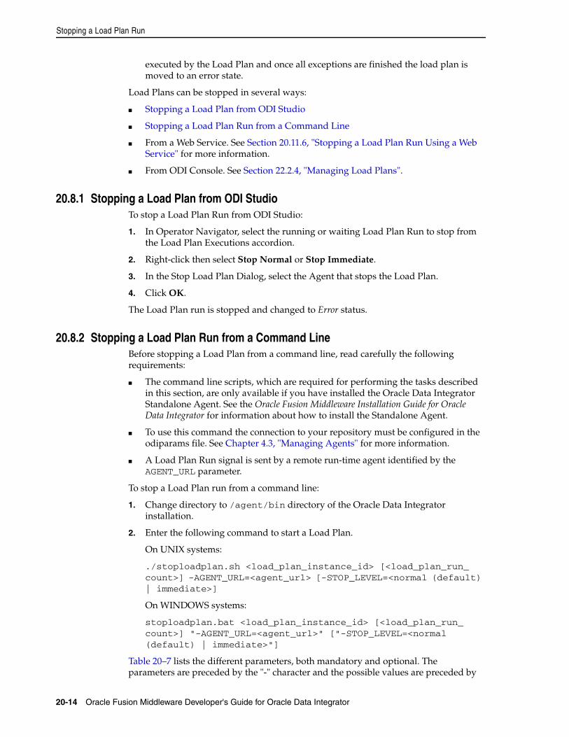
Stopping a Load Plan Run
20-14 Oracle Fusion Middleware Developer's Guide for Oracle Data Integrator
executed by the Load Plan and once all exceptions are finished the load plan is moved to an error state.
Load Plans can be stopped in several ways:
■ Stopping a Load Plan from ODI Studio
■ Stopping a Load Plan Run from a Command Line
■ From a Web Service. See Section 20.11.6, "Stopping a Load Plan Run Using a Web Service" for more information.
■ From ODI Console. See Section 22.2.4, "Managing Load Plans".
20.8.1 Stopping a Load Plan from ODI StudioTo stop a Load Plan Run from ODI Studio:
1. In Operator Navigator, select the running or waiting Load Plan Run to stop from the Load Plan Executions accordion.
2. Right-click then select Stop Normal or Stop Immediate.
3. In the Stop Load Plan Dialog, select the Agent that stops the Load Plan.
4. Click OK.
The Load Plan run is stopped and changed to Error status.
20.8.2 Stopping a Load Plan Run from a Command LineBefore stopping a Load Plan from a command line, read carefully the following requirements:
■ The command line scripts, which are required for performing the tasks described in this section, are only available if you have installed the Oracle Data Integrator Standalone Agent. See the Oracle Fusion Middleware Installation Guide for Oracle Data Integrator for information about how to install the Standalone Agent.
■ To use this command the connection to your repository must be configured in the odiparams file. See Chapter 4.3, "Managing Agents" for more information.
■ A Load Plan Run signal is sent by a remote run-time agent identified by the AGENT_URL parameter.
To stop a Load Plan run from a command line:
1. Change directory to /agent/bin directory of the Oracle Data Integrator installation.
2. Enter the following command to start a Load Plan.
On UNIX systems:
./stoploadplan.sh <load_plan_instance_id> [<load_plan_run_count>] -AGENT_URL=<agent_url> [-STOP_LEVEL=<normal (default) | immediate>]
On WINDOWS systems:
stoploadplan.bat <load_plan_instance_id> [<load_plan_run_count>] "-AGENT_URL=<agent_url>" ["-STOP_LEVEL=<normal (default) | immediate>"]
Table 20–7 lists the different parameters, both mandatory and optional. The parameters are preceded by the "-" character and the possible values are preceded by
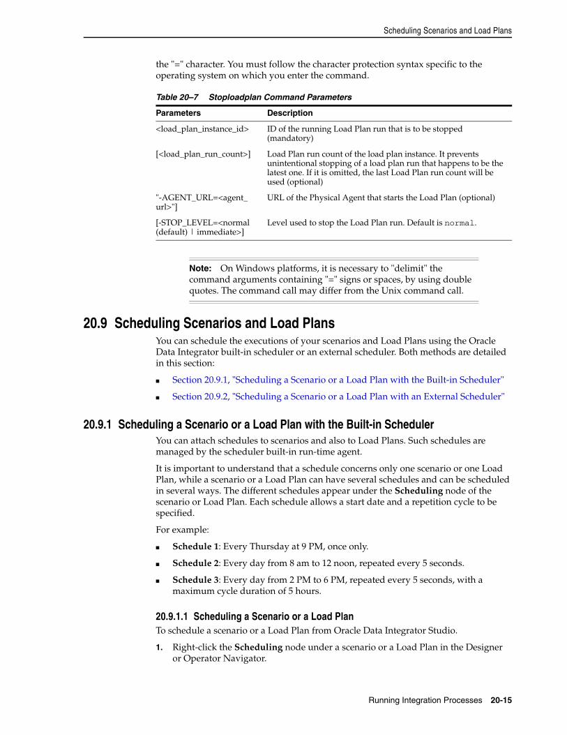
Scheduling Scenarios and Load Plans
Running Integration Processes 20-15
the "=" character. You must follow the character protection syntax specific to the operating system on which you enter the command.
20.9 Scheduling Scenarios and Load PlansYou can schedule the executions of your scenarios and Load Plans using the Oracle Data Integrator built-in scheduler or an external scheduler. Both methods are detailed in this section:
■ Section 20.9.1, "Scheduling a Scenario or a Load Plan with the Built-in Scheduler"
■ Section 20.9.2, "Scheduling a Scenario or a Load Plan with an External Scheduler"
20.9.1 Scheduling a Scenario or a Load Plan with the Built-in SchedulerYou can attach schedules to scenarios and also to Load Plans. Such schedules are managed by the scheduler built-in run-time agent.
It is important to understand that a schedule concerns only one scenario or one Load Plan, while a scenario or a Load Plan can have several schedules and can be scheduled in several ways. The different schedules appear under the Scheduling node of the scenario or Load Plan. Each schedule allows a start date and a repetition cycle to be specified.
For example:
■ Schedule 1: Every Thursday at 9 PM, once only.
■ Schedule 2: Every day from 8 am to 12 noon, repeated every 5 seconds.
■ Schedule 3: Every day from 2 PM to 6 PM, repeated every 5 seconds, with a maximum cycle duration of 5 hours.
20.9.1.1 Scheduling a Scenario or a Load PlanTo schedule a scenario or a Load Plan from Oracle Data Integrator Studio.
1. Right-click the Scheduling node under a scenario or a Load Plan in the Designer or Operator Navigator.
Table 20–7 Stoploadplan Command Parameters
Parameters Description
<load_plan_instance_id> ID of the running Load Plan run that is to be stopped (mandatory)
[<load_plan_run_count>] Load Plan run count of the load plan instance. It prevents unintentional stopping of a load plan run that happens to be the latest one. If it is omitted, the last Load Plan run count will be used (optional)
"-AGENT_URL=<agent_url>"]
URL of the Physical Agent that starts the Load Plan (optional)
[-STOP_LEVEL=<normal (default) | immediate>]
Level used to stop the Load Plan run. Default is normal.
Note: On Windows platforms, it is necessary to "delimit" the command arguments containing "=" signs or spaces, by using double quotes. The command call may differ from the Unix command call.
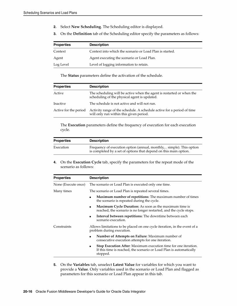
Scheduling Scenarios and Load Plans
20-16 Oracle Fusion Middleware Developer's Guide for Oracle Data Integrator
2. Select New Scheduling. The Scheduling editor is displayed.
3. On the Definition tab of the Scheduling editor specify the parameters as follows:
The Status parameters define the activation of the schedule.
The Execution parameters define the frequency of execution for each execution cycle.
4. On the Execution Cycle tab, specify the parameters for the repeat mode of the scenario as follows:
5. On the Variables tab, unselect Latest Value for variables for which you want to provide a Value. Only variables used in the scenario or Load Plan and flagged as parameters for this scenario or Load Plan appear in this tab.
Properties Description
Context Context into which the scenario or Load Plan is started.
Agent Agent executing the scenario or Load Plan.
Log Level Level of logging information to retain.
Properties Description
Active The scheduling will be active when the agent is restarted or when the scheduling of the physical agent is updated.
Inactive The schedule is not active and will not run.
Active for the period Activity range of the schedule. A schedule active for a period of time will only run within this given period.
Properties Description
Execution Frequency of execution option (annual, monthly,... simple). This option is completed by a set of options that depend on this main option.
Properties Description
None (Execute once) The scenario or Load Plan is executed only one time.
Many times The scenario or Load Plan is repeated several times.
■ Maximum number of repetitions: The maximum number of times the scenario is repeated during the cycle.
■ Maximum Cycle Duration: As soon as the maximum time is reached, the scenario is no longer restarted, and the cycle stops.
■ Interval between repetitions: The downtime between each scenario execution.
Constraints Allows limitations to be placed on one cycle iteration, in the event of a problem during execution.
■ Number of Attempts on Failure: Maximum number of consecutive execution attempts for one iteration.
■ Stop Execution After: Maximum execution time for one iteration. If this time is reached, the scenario or Load Plan is automatically stopped.
Scheduling Scenarios and Load Plans
Running Integration Processes 20-17
6. From the File menu, click Save.
The new schedule appears under the Scheduling node of the scenario or Load Plan.
The schedule changes are taken into account by the run-time agent when it starts or when it receives a schedule update request.
20.9.1.2 Updating an Agent’s ScheduleAn agent reads schedules when starting on all the repositories attached to the master repository it connects to. It is possible, if a schedule was added for this agent in a given repository, to refresh the agent schedule.
To update an agent’s schedule:
1. In Topology Navigator expand the Agents node in the Physical Architecture accordion.
2. Select the Physical Agent you want to update the schedule.
3. Right-click and select Update Scheduling...
4. In the Select Repositories dialog, select the repositories from which you want to read scheduling information. Check Select All Work Repositories to read scheduling information from all these repositories.
5. Click OK.
The agent refreshes and re-computes its in-memory schedule from the schedules defined in these repositories.
You can also use the OdiUpdateAgentSchedule tool to update an agent’s schedule.
20.9.1.3 Displaying the ScheduleYou can view the scheduled tasks of all your agents or you can view the scheduled tasks of one particular agent.
Displaying the Schedule for All AgentTo display the schedule for all agents:
1. Select Connect Navigator >Scheduling... from the Operator Navigator toolbar menu.
The View Schedule dialog appears, displaying the schedule for all agents.
Displaying the Schedule for One AgentTo display the schedule for one agent:
1. In Topology Navigator expand the Agents node in the Physical Architecture accordion.
2. Select the Physical Agent you want to update the schedule.
3. Right-click and select View Schedule.
The Schedule Editor appears, displaying the schedule for this agent.
Note: The Scheduling Information is retrieved from the Agent's in-memory schedule. The Agent must be started and its schedule refreshed in order to display accurate schedule information.
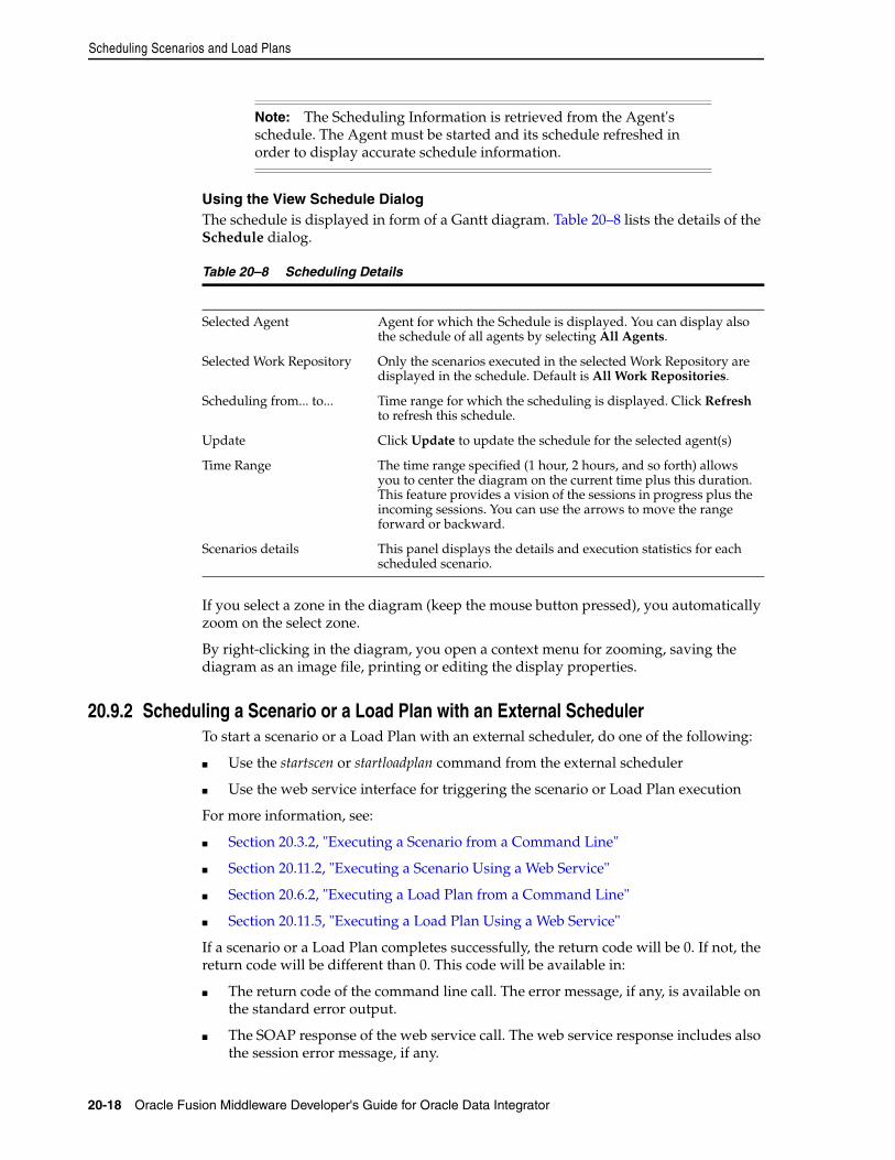
Scheduling Scenarios and Load Plans
20-18 Oracle Fusion Middleware Developer's Guide for Oracle Data Integrator
Using the View Schedule DialogThe schedule is displayed in form of a Gantt diagram. Table 20–8 lists the details of the Schedule dialog.
If you select a zone in the diagram (keep the mouse button pressed), you automatically zoom on the select zone.
By right-clicking in the diagram, you open a context menu for zooming, saving the diagram as an image file, printing or editing the display properties.
20.9.2 Scheduling a Scenario or a Load Plan with an External SchedulerTo start a scenario or a Load Plan with an external scheduler, do one of the following:
■ Use the startscen or startloadplan command from the external scheduler
■ Use the web service interface for triggering the scenario or Load Plan execution
For more information, see:
■ Section 20.3.2, "Executing a Scenario from a Command Line"
■ Section 20.11.2, "Executing a Scenario Using a Web Service"
■ Section 20.6.2, "Executing a Load Plan from a Command Line"
■ Section 20.11.5, "Executing a Load Plan Using a Web Service"
If a scenario or a Load Plan completes successfully, the return code will be 0. If not, the return code will be different than 0. This code will be available in:
■ The return code of the command line call. The error message, if any, is available on the standard error output.
■ The SOAP response of the web service call. The web service response includes also the session error message, if any.
Note: The Scheduling Information is retrieved from the Agent's schedule. The Agent must be started and its schedule refreshed in order to display accurate schedule information.
Table 20–8 Scheduling Details
Selected Agent Agent for which the Schedule is displayed. You can display also the schedule of all agents by selecting All Agents.
Selected Work Repository Only the scenarios executed in the selected Work Repository are displayed in the schedule. Default is All Work Repositories.
Scheduling from... to... Time range for which the scheduling is displayed. Click Refresh to refresh this schedule.
Update Click Update to update the schedule for the selected agent(s)
Time Range The time range specified (1 hour, 2 hours, and so forth) allows you to center the diagram on the current time plus this duration. This feature provides a vision of the sessions in progress plus the incoming sessions. You can use the arrows to move the range forward or backward.
Scenarios details This panel displays the details and execution statistics for each scheduled scenario.
Managing Executions Using Web Services
Running Integration Processes 20-19
20.10 Simulating an ExecutionIn Oracle Data Integrator you have the possibility at design-time to simulate an execution. Simulating an execution generates and displays the code corresponding to the execution without running this code. Execution simulation provides reports suitable for code review.
To simulate an execution:
1. In the Project view of the Designer Navigator, select the object you want to execute.
2. Right-click and select Execute.
3. In the Execution dialog, set the execution parameters and select Simulation. See Table 20–1 for more information.
4. Click OK.
The Simulation report is displayed.
You can click Save to save the report as.xml or.html file.
20.11 Managing Executions Using Web ServicesThis section explains how to use a web service to perform run-time operations. it contains the following sections.
■ Section 20.11.1, "Introduction to Run-Time Web Services"
■ Section 20.11.2, "Executing a Scenario Using a Web Service"
■ Section 20.11.3, "Monitoring a Session Status Using a Web Service"
■ Section 20.11.4, "Restarting a Session Using a Web Service"
■ Section 20.11.5, "Executing a Load Plan Using a Web Service"
■ Section 20.11.6, "Stopping a Load Plan Run Using a Web Service"
■ Section 20.11.7, "Restarting a Load Plan Instance Using a Web Service"
■ Section 20.11.8, "Monitoring a Load Plan Run Status Using a Web Service"
■ Section 20.11.9, "Listing Contexts Using a Web Service"
■ Section 20.11.10, "Listing Scenarios Using a Web Service"
■ Section 20.11.11, "Accessing the Web Service from a Command Line"
■ Section 20.11.12, "Using the Run-Time Web Services with External Authentication"
■ Section 20.11.13, "Using WS-Addressing"
■ Section 20.11.14, "Using Asynchronous Web Services with Callback"
20.11.1 Introduction to Run-Time Web ServicesOracle Data Integrator includes web services for performing run-time operations. These web services are located in two places:
Note: No session is created in the log when the execution is started in simulation mode.
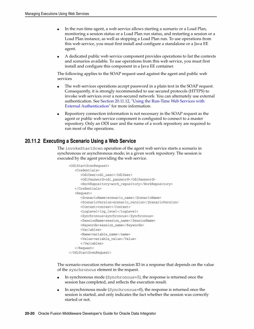
Managing Executions Using Web Services
20-20 Oracle Fusion Middleware Developer's Guide for Oracle Data Integrator
■ In the run-time agent, a web service allows starting a scenario or a Load Plan, monitoring a session status or a Load Plan run status, and restarting a session or a Load Plan instance, as well as stopping a Load Plan run. To use operations from this web service, you must first install and configure a standalone or a Java EE agent.
■ A dedicated public web service component provides operations to list the contexts and scenarios available. To use operations from this web service, you must first install and configure this component in a Java EE container.
The following applies to the SOAP request used against the agent and public web services
■ The web services operations accept password in a plain text in the SOAP request. Consequently, it is strongly recommended to use secured protocols (HTTPS) to invoke web services over a non-secured network. You can alternately use external authentication. See Section 20.11.12, "Using the Run-Time Web Services with External Authentication" for more information.
■ Repository connection information is not necessary in the SOAP request as the agent or public web service component is configured to connect to a master repository. Only an ODI user and the name of a work repository are required to run most of the operations.
20.11.2 Executing a Scenario Using a Web ServiceThe invokeStartScen operation of the agent web service starts a scenario in synchronous or asynchronous mode; in a given work repository. The session is executed by the agent providing the web service.
<OdiStartScenRequest> <Credentials> <OdiUser>odi_user</OdiUser> <OdiPassword>odi_password</OdiPassword> <WorkRepository>work_repository</WorkRepository> </Credentials> <Request> <ScenarioName>scenario_name</ScenarioName> <ScenarioVersion>scenario_version</ScenarioVersion> <Context>context</Context> <LogLevel>log_level</LogLevel> <Synchronous>synchronous</Synchronous> <SessionName>session_name</SessionName> <Keywords>session_name</Keywords> <Variables> <Name>variable_name</name> <Value>variable_value</Value> </Variables> </Request> </OdiStartScenRequest>
The scenario execution returns the session ID in a response that depends on the value of the synchronous element in the request.
■ In synchronous mode (Synchronous=1), the response is returned once the session has completed, and reflects the execution result.
■ In asynchronous mode (Synchronous=0), the response is returned once the session is started, and only indicates the fact whether the session was correctly started or not.
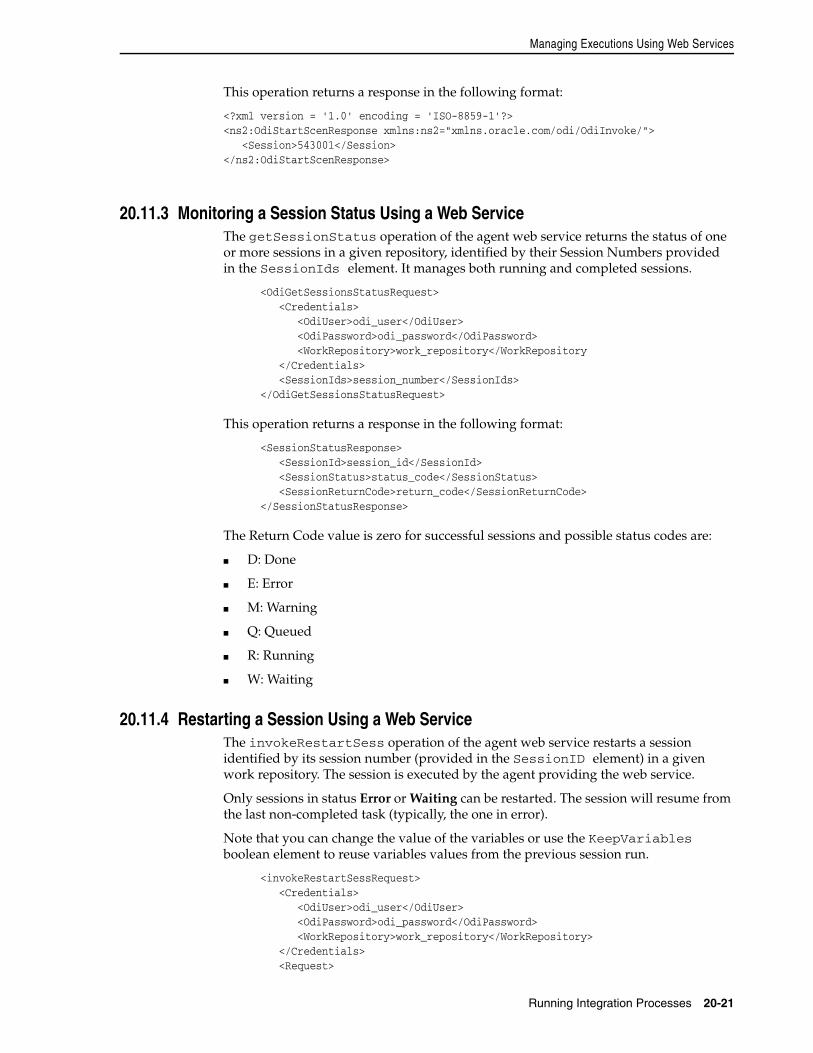
Managing Executions Using Web Services
Running Integration Processes 20-21
This operation returns a response in the following format:
<?xml version = '1.0' encoding = 'ISO-8859-1'?><ns2:OdiStartScenResponse xmlns:ns2="xmlns.oracle.com/odi/OdiInvoke/"> <Session>543001</Session></ns2:OdiStartScenResponse>
20.11.3 Monitoring a Session Status Using a Web ServiceThe getSessionStatus operation of the agent web service returns the status of one or more sessions in a given repository, identified by their Session Numbers provided in the SessionIds element. It manages both running and completed sessions.
<OdiGetSessionsStatusRequest> <Credentials> <OdiUser>odi_user</OdiUser> <OdiPassword>odi_password</OdiPassword> <WorkRepository>work_repository</WorkRepository </Credentials> <SessionIds>session_number</SessionIds> </OdiGetSessionsStatusRequest>
This operation returns a response in the following format:
<SessionStatusResponse> <SessionId>session_id</SessionId> <SessionStatus>status_code</SessionStatus> <SessionReturnCode>return_code</SessionReturnCode> </SessionStatusResponse>
The Return Code value is zero for successful sessions and possible status codes are:
■ D: Done
■ E: Error
■ M: Warning
■ Q: Queued
■ R: Running
■ W: Waiting
20.11.4 Restarting a Session Using a Web ServiceThe invokeRestartSess operation of the agent web service restarts a session identified by its session number (provided in the SessionID element) in a given work repository. The session is executed by the agent providing the web service.
Only sessions in status Error or Waiting can be restarted. The session will resume from the last non-completed task (typically, the one in error).
Note that you can change the value of the variables or use the KeepVariables boolean element to reuse variables values from the previous session run.
<invokeRestartSessRequest> <Credentials> <OdiUser>odi_user</OdiUser> <OdiPassword>odi_password</OdiPassword> <WorkRepository>work_repository</WorkRepository> </Credentials> <Request>
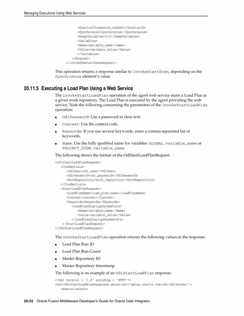
Managing Executions Using Web Services
20-22 Oracle Fusion Middleware Developer's Guide for Oracle Data Integrator
<SessionID>session_number</SessionID> <Synchronous>synchronous</Synchronous> <KeepVariables>0|1</KeepVariables> <Variables> <Name>variable_name</name> <Value>variable_value</Value> </Variables> </Request> </invokeRestartSessRequest>
This operation returns a response similar to InvokeStartScen, depending on the Synchronous element’s value.
20.11.5 Executing a Load Plan Using a Web ServiceThe invokeStartLoadPlan operation of the agent web service starts a Load Plan in a given work repository. The Load Plan is executed by the agent providing the web service. Note the following concerning the parameters of the invokeStartLoadPlan operation:
■ OdiPassword: Use a password in clear text.
■ Context: Use the context code.
■ Keywords: If you use several keywords, enter a comma separated list of keywords.
■ Name: Use the fully qualified name for variables: GLOBAL.variable_name or PROJECT_CODE.variable_name
The following shows the format of the OdiStartLoadPlanRequest.
<OdiStartLoadPlanRequest> <Credentials> <OdiUser>odi_user</OdiUser> <OdiPassword>odi_password</OdiPassword> <WorkRepository>work_repository</WorkRepository> </Credentials> <StartLoadPlanRequest> <LoadPlanName>load_plan_name</LoadPlanName> <Context>context</Context> <Keywords>keywords</Keywords> <LoadPlanStartupParameters> <Name>variable_name</Name> <Value>variable_value</Value> </LoadPlanStartupParameters> </StartLoadPlanRequest></OdiStartLoadPlanRequest>
The invokeStartLoadPlan operation returns the following values in the response:
■ Load Plan Run ID
■ Load Plan Run Count
■ Master Repository ID
■ Master Repository timestamp
The following is an example of an OdiStartLoadPlan response:
<?xml version = '1.0' encoding = 'UTF8'?><ns2:OdiStartLoadPlanResponse xmlns:ns2="xmlns.oracle.com/odi/OdiInvoke/"> <executionInfo>
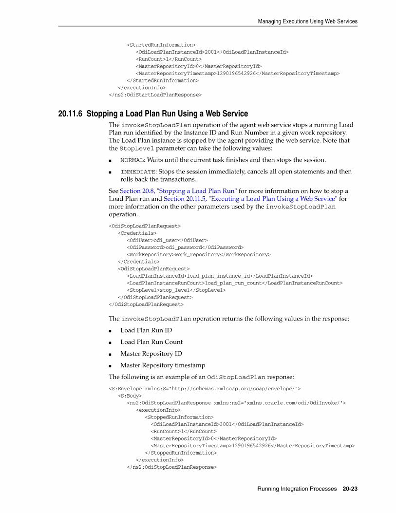
Managing Executions Using Web Services
Running Integration Processes 20-23
<StartedRunInformation> <OdiLoadPlanInstanceId>2001</OdiLoadPlanInstanceId> <RunCount>1</RunCount> <MasterRepositoryId>0</MasterRepositoryId> <MasterRepositoryTimestamp>1290196542926</MasterRepositoryTimestamp> </StartedRunInformation> </executionInfo></ns2:OdiStartLoadPlanResponse>
20.11.6 Stopping a Load Plan Run Using a Web ServiceThe invokeStopLoadPlan operation of the agent web service stops a running Load Plan run identified by the Instance ID and Run Number in a given work repository. The Load Plan instance is stopped by the agent providing the web service. Note that the StopLevel parameter can take the following values:
■ NORMAL: Waits until the current task finishes and then stops the session.
■ IMMEDIATE: Stops the session immediately, cancels all open statements and then rolls back the transactions.
See Section 20.8, "Stopping a Load Plan Run" for more information on how to stop a Load Plan run and Section 20.11.5, "Executing a Load Plan Using a Web Service" for more information on the other parameters used by the invokeStopLoadPlan operation.
<OdiStopLoadPlanRequest> <Credentials> <OdiUser>odi_user</OdiUser> <OdiPassword>odi_password</OdiPassword> <WorkRepository>work_repository</WorkRepository> </Credentials> <OdiStopLoadPlanRequest> <LoadPlanInstanceId>load_plan_instance_id</LoadPlanInstanceId> <LoadPlanInstanceRunCount>load_plan_run_count</LoadPlanInstanceRunCount> <StopLevel>stop_level</StopLevel> </OdiStopLoadPlanRequest></OdiStopLoadPlanRequest>
The invokeStopLoadPlan operation returns the following values in the response:
■ Load Plan Run ID
■ Load Plan Run Count
■ Master Repository ID
■ Master Repository timestamp
The following is an example of an OdiStopLoadPlan response:
<S:Envelope xmlns:S="http://schemas.xmlsoap.org/soap/envelope/"> <S:Body> <ns2:OdiStopLoadPlanResponse xmlns:ns2="xmlns.oracle.com/odi/OdiInvoke/"> <executionInfo> <StoppedRunInformation> <OdiLoadPlanInstanceId>3001</OdiLoadPlanInstanceId> <RunCount>1</RunCount> <MasterRepositoryId>0</MasterRepositoryId> <MasterRepositoryTimestamp>1290196542926</MasterRepositoryTimestamp> </StoppedRunInformation> </executionInfo> </ns2:OdiStopLoadPlanResponse>
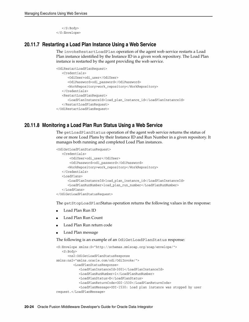
Managing Executions Using Web Services
20-24 Oracle Fusion Middleware Developer's Guide for Oracle Data Integrator
</S:Body></S:Envelope>
20.11.7 Restarting a Load Plan Instance Using a Web ServiceThe invokeRestartLoadPlan operation of the agent web service restarts a Load Plan instance identified by the Instance ID in a given work repository. The Load Plan instance is restarted by the agent providing the web service.
<OdiRestartLoadPlanRequest> <Credentials> <OdiUser>odi_user</OdiUser> <OdiPassword>odi_password</OdiPassword> <WorkRepository>work_repository</WorkRepository> </Credentials> <RestartLoadPlanRequest> <LoadPlanInstanceId>load_plan_instance_id</LoadPlanInstanceId> </RestartLoadPlanRequest></OdiRestartLoadPlanRequest>
20.11.8 Monitoring a Load Plan Run Status Using a Web ServiceThe getLoadPlanStatus operation of the agent web service returns the status of one or more Load Plans by their Instance ID and Run Number in a given repository. It manages both running and completed Load Plan instances.
<OdiGetLoadPlanStatusRequest> <Credentials> <OdiUser>odi_user</OdiUser> <OdiPassword>odi_password</OdiPassword> <WorkRepository>work_repository</WorkRepository> </Credentials> <LoadPlans> <LoadPlanInstanceId>load_plan_instance_id</LoadPlanInstanceId> <LoadPlanRunNumber>load_plan_run_number</LoadPlanRunNumber> </LoadPlans> </OdiGetLoadPlanStatusRequest>
The getStopLoadPlanStatus operation returns the following values in the response:
■ Load Plan Run ID
■ Load Plan Run Count
■ Load Plan Run return code
■ Load Plan message
The following is an example of an OdiGetLoadPlanStatus response:
<S:Envelope xmlns:S="http://schemas.xmlsoap.org/soap/envelope/"> <S:Body> <ns2:OdiGetLoadPlanStatusResponse xmlns:ns2="xmlns.oracle.com/odi/OdiInvoke/"> <LoadPlanStatusResponse> <LoadPlanInstanceId>3001</LoadPlanInstanceId> <LoadPlanRunNumber>1</LoadPlanRunNumber> <LoadPlanStatus>E</LoadPlanStatus> <LoadPlanReturnCode>ODI-1530</LoadPlanReturnCode> <LoadPlanMessage>ODI-1530: Load plan instance was stopped by user request.</LoadPlanMessage>
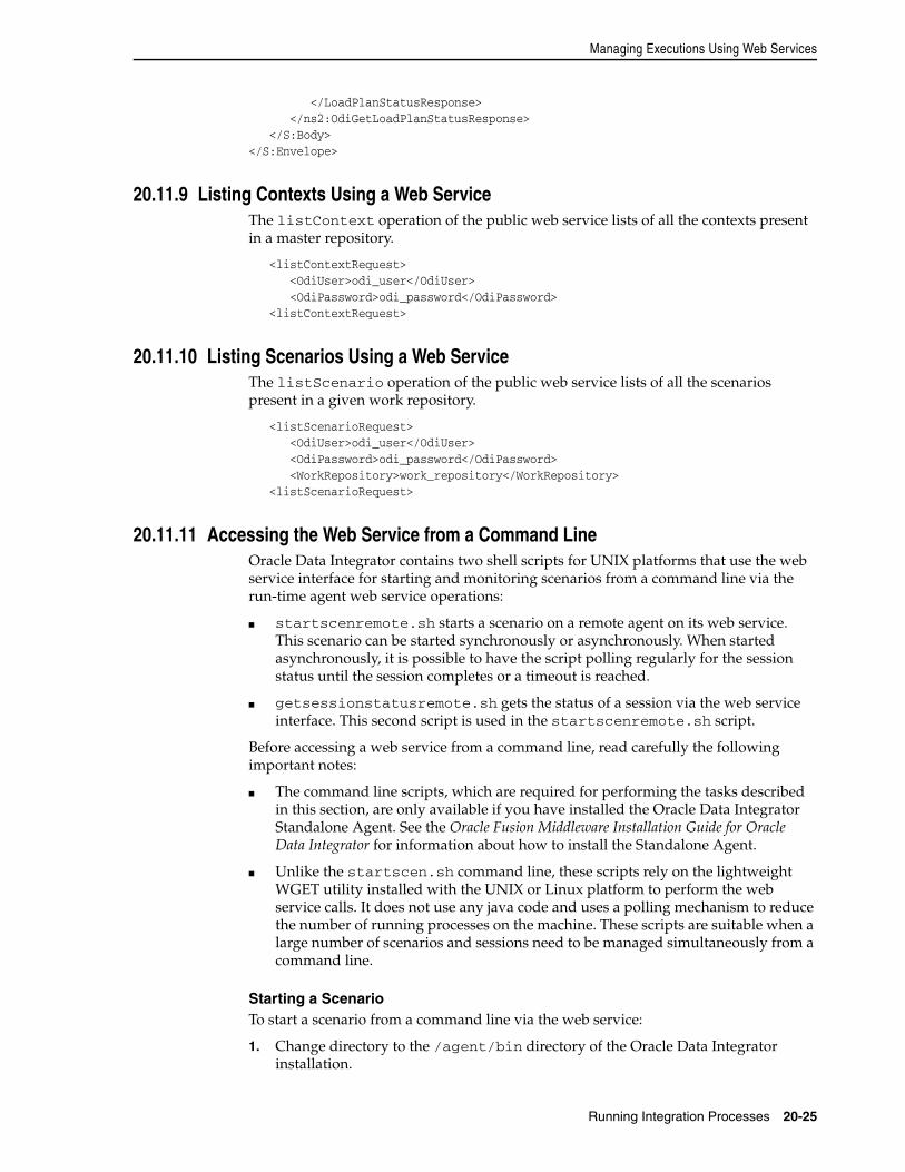
Managing Executions Using Web Services
Running Integration Processes 20-25
</LoadPlanStatusResponse> </ns2:OdiGetLoadPlanStatusResponse> </S:Body></S:Envelope>
20.11.9 Listing Contexts Using a Web ServiceThe listContext operation of the public web service lists of all the contexts present in a master repository.
<listContextRequest> <OdiUser>odi_user</OdiUser> <OdiPassword>odi_password</OdiPassword> <listContextRequest>
20.11.10 Listing Scenarios Using a Web ServiceThe listScenario operation of the public web service lists of all the scenarios present in a given work repository.
<listScenarioRequest> <OdiUser>odi_user</OdiUser> <OdiPassword>odi_password</OdiPassword> <WorkRepository>work_repository</WorkRepository> <listScenarioRequest>
20.11.11 Accessing the Web Service from a Command LineOracle Data Integrator contains two shell scripts for UNIX platforms that use the web service interface for starting and monitoring scenarios from a command line via the run-time agent web service operations:
■ startscenremote.sh starts a scenario on a remote agent on its web service. This scenario can be started synchronously or asynchronously. When started asynchronously, it is possible to have the script polling regularly for the session status until the session completes or a timeout is reached.
■ getsessionstatusremote.sh gets the status of a session via the web service interface. This second script is used in the startscenremote.sh script.
Before accessing a web service from a command line, read carefully the following important notes:
■ The command line scripts, which are required for performing the tasks described in this section, are only available if you have installed the Oracle Data Integrator Standalone Agent. See the Oracle Fusion Middleware Installation Guide for Oracle Data Integrator for information about how to install the Standalone Agent.
■ Unlike the startscen.sh command line, these scripts rely on the lightweight WGET utility installed with the UNIX or Linux platform to perform the web service calls. It does not use any java code and uses a polling mechanism to reduce the number of running processes on the machine. These scripts are suitable when a large number of scenarios and sessions need to be managed simultaneously from a command line.
Starting a ScenarioTo start a scenario from a command line via the web service:
1. Change directory to the /agent/bin directory of the Oracle Data Integrator installation.
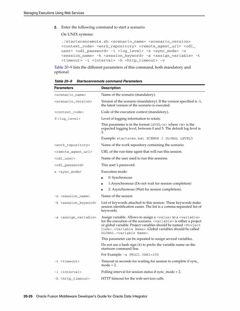
Managing Executions Using Web Services
20-26 Oracle Fusion Middleware Developer's Guide for Oracle Data Integrator
2. Enter the following command to start a scenario.
On UNIX systems:
./startscenremote.sh <scenario_name> <scenario_version> <context_code> <work_repository> <remote_agent_url> <odi_user> <odi_password> -l <log_level> -s <sync_mode> -n <session_name> -k <session_keyword> -a <assign_variable> -t <timeout> -i <interval> -h <http_timeout> -v
Table 20–9 lists the different parameters of this command, both mandatory and optional.
Table 20–9 Startscenremote command Parameters
Parameters Description
<scenario_name> Name of the scenario (mandatory).
<scenario_version> Version of the scenario (mandatory). If the version specified is -1, the latest version of the scenario is executed.
<context_code> Code of the execution context (mandatory).
-l <log_level> Level of logging information to retain.
This parameter is in the format LEVEL<n> where <n> is the expected logging level, between 0 and 5. The default log level is 5.
Example: startscen.bat SCENAR 1 GLOBAL LEVEL5
<work_repository> Name of the work repository containing the scenario.
<remote_agent_url> URL of the run-time agent that will run this session.
<odi_user> Name of the user used to run this sessions.
<odi_password> This user’s password.
s <sync_mode> Execution mode:
■ 0: Synchronous
■ 1:Asynchronous (Do not wait for session completion)
■ 2: Asynchronous (Wait for session completion).
-n <session_name> Name of the session
-k <session_keyword> List of keywords attached to this session. These keywords make session identification easier. The list is a comma-separated list of keywords.
-a <assign_variable> Assign variable. Allows to assign a <value> to a <variable> for the execution of the scenario. <variable> is either a project or global variable. Project variables should be named <Project Code>.<Variable Name>. Global variables should be called GLOBAL.<variable Name>.
This parameter can be repeated to assign several variables.
Do not use a hash sign (#) to prefix the variable name on the startscen command line.
For Example: -a PROJ1.VAR1=100
-t <timeout> Timeout in seconds for waiting for session to complete if sync_mode = 2.
-i <interval> Polling interval for session status if sync_mode = 2.
-h <http_timeout> HTTP timeout for the web services calls.
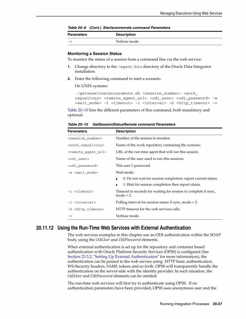
Managing Executions Using Web Services
Running Integration Processes 20-27
Monitoring a Session StatusTo monitor the status of a session from a command line via the web service:
1. Change directory to the /agent/bin directory of the Oracle Data Integrator installation.
2. Enter the following command to start a scenario.
On UNIX systems:
./getsessionstatusremote.sh <session_number> <work_repository> <remote_agent_url> <odi_user> <odi_password> -w <wait_mode> -t <timeout> -i <interval> -h <http_timeout> -v
Table 20–10 lists the different parameters of this command, both mandatory and optional.
20.11.12 Using the Run-Time Web Services with External AuthenticationThe web services examples in this chapter use an ODI authentication within the SOAP body, using the OdiUser and OdiPassword elements.
When external authentication is set up for the repository and container based authentication with Oracle Platform Security Services (OPSS) is configured (See Section 23.3.2, "Setting Up External Authentication" for more information), the authentication can be passed to the web service using HTTP basic authentication, WS-Security headers, SAML tokens and so forth. OPSS will transparently handle the authentication on the server-side with the identity provider. In such situation, the OdiUser and OdiPassword elements can be omitted.
The run-time web services will first try to authenticate using OPSS. If no authentication parameters have been provided, OPSS uses anonymous user and the
-v Verbose mode.
Table 20–10 GetSessionStatusRemote command Parameters
Parameters Description
<session_number> Number of the session to monitor.
<work_repository> Name of the work repository containing the scenario.
<remote_agent_url> URL of the run-time agent that will run this session.
<odi_user> Name of the user used to run this sessions.
<odi_password> This user’s password.
-w <wait_mode> Wait mode:
■ 0: Do not wait for session completion, report current status.
■ 1: Wait for session completion then report status.
-t <timeout> Timeout in seconds for waiting for session to complete if sync_mode = 2.
-i <interval> Polling interval for session status if sync_mode = 2.
-h <http_timeout> HTTP timeout for the web services calls.
-v Verbose mode.
Table 20–9 (Cont.) Startscenremote command Parameters
Parameters Description
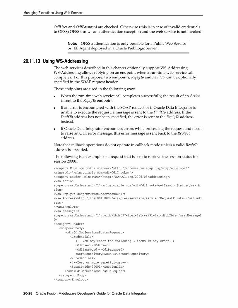
Managing Executions Using Web Services
20-28 Oracle Fusion Middleware Developer's Guide for Oracle Data Integrator
OdiUser and OdiPassword are checked. Otherwise (this is in case of invalid credentials to OPSS) OPSS throws an authentication exception and the web service is not invoked.
20.11.13 Using WS-AddressingThe web services described in this chapter optionally support WS-Addressing. WS-Addressing allows replying on an endpoint when a run-time web service call completes. For this purpose, two endpoints, ReplyTo and FaultTo, can be optionally specified in the SOAP request header.
These endpoints are used in the following way:
■ When the run-time web service call completes successfully, the result of an Action is sent to the ReplyTo endpoint.
■ If an error is encountered with the SOAP request or if Oracle Data Integrator is unable to execute the request, a message is sent to the FaultTo address. If the FaultTo address has not been specified, the error is sent to the ReplyTo address instead.
■ If Oracle Data Integrator encounters errors while processing the request and needs to raise an ODI error message, this error message is sent back to the ReplyTo address.
Note that callback operations do not operate in callback mode unless a valid ReplyTo address is specified.
The following is an example of a request that is sent to retrieve the session status for session 20001:
<soapenv:Envelope xmlns:soapenv="http://schemas.xmlsoap.org/soap/envelope/" xmlns:odi="xmlns.oracle.com/odi/OdiInvoke/"><soapenv:Header xmlns:wsa="http://www.w3.org/2005/08/addressing"><wsa:Action soapenv:mustUnderstand="1">xmlns.oracle.com/odi/OdiInvoke/getSessionStatus</wsa:Action><wsa:ReplyTo soapenv:mustUnderstand="1"><wsa:Address>http://host001:8080/examples/servlets/servlet/RequestPrinter</wsa:Address></wsa:ReplyTo><wsa:MessageID soapenv:mustUnderstand="1">uuid:71bd2037-fbef-4e1c-a991-4afcd8cb2b8e</wsa:MessageID></soapenv:Header> <soapenv:Body> <odi:OdiGetSessionsStatusRequest> <Credentials> <!--You may enter the following 3 items in any order--> <OdiUser></OdiUser> <OdiPassword></OdiPassword> <WorkRepository>WORKREP1</WorkRepository> </Credentials> <!--Zero or more repetitions:--> <SessionIds>20001</SessionIds> </odi:OdiGetSessionsStatusRequest> </soapenv:Body></soapenv:Envelope>
Note: OPSS authentication is only possible for a Public Web Service or JEE Agent deployed in a Oracle WebLogic Server.
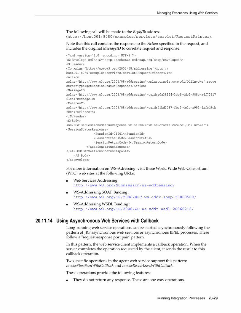
Managing Executions Using Web Services
Running Integration Processes 20-29
The following call will be made to the ReplyTo address (http://host001:8080/examples/servlets/servlet/RequestPrinter).
Note that this call contains the response to the Action specified in the request, and includes the original MessageID to correlate request and response.
<?xml version='1.0' encoding='UTF-8'?><S:Envelope xmlns:S="http://schemas.xmlsoap.org/soap/envelope/"><S:Header><To xmlns="http://www.w3.org/2005/08/addressing">http:// host001:8080/examples/servlets/servlet/RequestPrinter</To><Action xmlns="http://www.w3.org/2005/08/addressing">xmlns.oracle.com/odi/OdiInvoke/:requestPortType:getSessionStatusResponse</Action><MessageID xmlns="http://www.w3.org/2005/08/addressing">uuid:eda383f4-3cb5-4dc2-988c-a4f7051763ea</MessageID><RelatesTo xmlns="http://www.w3.org/2005/08/addressing">uuid:71bd2037-fbef-4e1c-a991-4afcd8cb2b8e</RelatesTo></S:Header><S:Body><ns2:OdiGetSessionsStatusResponse xmlns:ns2="xmlns.oracle.com/odi/OdiInvoke/"><SessionStatusResponse> <SessionId>26001</SessionId> <SessionStatus>D</SessionStatus> <SessionReturnCode>0</SessionReturnCode> </SessionStatusResponse></ns2:OdiGetSessionsStatusResponse> </S:Body></S:Envelope>
For more information on WS-Adressing, visit these World Wide Web Consortium (W3C) web sites at the following URLs:
■ Web Services Addressing: http://www.w3.org/Submission/ws-addressing/
■ WS-Addressing SOAP Binding : http://www.w3.org/TR/2006/REC-ws-addr-soap-20060509/
■ WS-Addressing WSDL Binding : http://www.w3.org/TR/2006/WD-ws-addr-wsdl-20060216/
20.11.14 Using Asynchronous Web Services with CallbackLong-running web service operations can be started asynchronously following the pattern of JRF asynchronous web services or asynchronous BPEL processes. These follow a "request-response port pair" pattern.
In this pattern, the web service client implements a callback operation. When the server completes the operation requested by the client, it sends the result to this callback operation.
Two specific operations in the agent web service support this pattern: invokeStartScenWithCallback and invokeRestartSessWithCallback.
These operations provide the following features:
■ They do not return any response. These are one way operations.
Managing Executions Using Web Services
20-30 Oracle Fusion Middleware Developer's Guide for Oracle Data Integrator
■ The client invoking these two operation must implement respectively the invokeStartSceCallback and invokeRestartSessCallback one way operations. Results from the invokeStartScenWithCallback and invokeRestartSessWithCallback actions are sent to these operations.
■ The invocation should provide in the SOAP header the ReplyTo and possibly FaultTo addresses. If the methods are invoked without a ReplyTo address, the operation will execute synchronously (which corresponds to a invokeStartScen or invokeRestartSess operation). When a fault is generated in the operation, it will be sent to the ReplyTo address or FaultTo address.
A scenario or session started synchronously using the invokeStartScenWithCallback and invokeRestartSessWithCallback will start and will not return any SOAP response, as they are one way operations. When the session completes, the response is sent the callback address.
Note: Oracle BPEL takes care of automatically implementing these operations and sends out WS-Addressing headers that point to these endpoints.
21
Monitoring Integration Processes 21-1
21Monitoring Integration Processes
This chapter describes how to manage your development executions in Operator Navigator. An overview of the Operator Navigator’s user interface is provided.
This chapter includes the following sections:
■ Section 21.1, "Introduction to Monitoring"
■ Section 21.2, "Monitoring Executions Results"
■ Section 21.3, "Managing your Executions"
21.1 Introduction to MonitoringMonitoring your development executions consists of viewing the execution results and managing the development executions when the executions are successful or in error. This section provides an introduction to the monitoring features in Oracle Data Integrator. How to work with your execution results is covered in Section 21.2, "Monitoring Executions Results". How to manage your development executions is covered in Section 21.3, "Managing your Executions".
21.1.1 Introduction to Operator NavigatorThrough Operator Navigator, you can view your execution results and manage your development executions in the sessions, as well as the scenarios and Load Plans in production.
Operator Navigator stores this information in a work repository, while using the topology defined in the master repository.
Operator Navigator displays the objects available to the current user in six accordions:
■ Session List displays all sessions organized per date, physical agent, status, keywords, and so forth
■ Hierarchical Sessions displays the execution sessions also organized in a hierarchy with their child sessions
■ Load Plan Executions displays the Load Plan Runs of the Load Plan instances
■ Scheduling displays the list of physical agents and schedules
■ Load Plans and Scenarios displays the list of scenarios and Load Plans available
■ Solutions displays the list of solutions
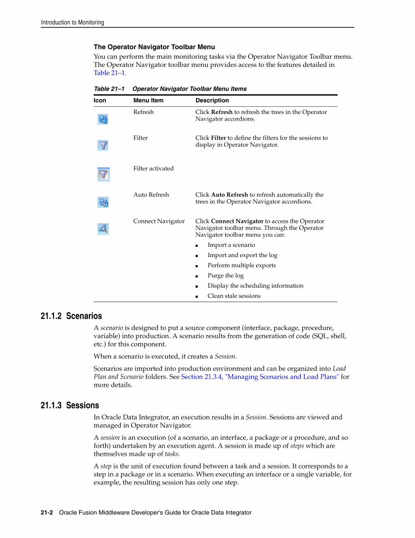
Introduction to Monitoring
21-2 Oracle Fusion Middleware Developer's Guide for Oracle Data Integrator
The Operator Navigator Toolbar MenuYou can perform the main monitoring tasks via the Operator Navigator Toolbar menu. The Operator Navigator toolbar menu provides access to the features detailed in Table 21–1.
21.1.2 ScenariosA scenario is designed to put a source component (interface, package, procedure, variable) into production. A scenario results from the generation of code (SQL, shell, etc.) for this component.
When a scenario is executed, it creates a Session.
Scenarios are imported into production environment and can be organized into Load Plan and Scenario folders. See Section 21.3.4, "Managing Scenarios and Load Plans" for more details.
21.1.3 SessionsIn Oracle Data Integrator, an execution results in a Session. Sessions are viewed and managed in Operator Navigator.
A session is an execution (of a scenario, an interface, a package or a procedure, and so forth) undertaken by an execution agent. A session is made up of steps which are themselves made up of tasks.
A step is the unit of execution found between a task and a session. It corresponds to a step in a package or in a scenario. When executing an interface or a single variable, for example, the resulting session has only one step.
Table 21–1 Operator Navigator Toolbar Menu Items
Icon Menu Item Description
Refresh Click Refresh to refresh the trees in the Operator Navigator accordions.
Filter
Filter activated
Click Filter to define the filters for the sessions to display in Operator Navigator.
Auto Refresh Click Auto Refresh to refresh automatically the trees in the Operator Navigator accordions.
Connect Navigator Click Connect Navigator to access the Operator Navigator toolbar menu. Through the Operator Navigator toolbar menu you can:
■ Import a scenario
■ Import and export the log
■ Perform multiple exports
■ Purge the log
■ Display the scheduling information
■ Clean stale sessions
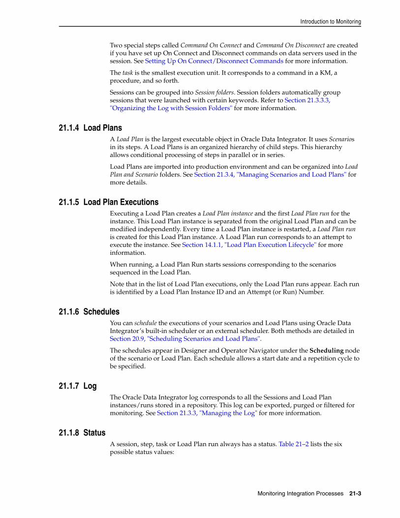
Introduction to Monitoring
Monitoring Integration Processes 21-3
Two special steps called Command On Connect and Command On Disconnect are created if you have set up On Connect and Disconnect commands on data servers used in the session. See Setting Up On Connect/Disconnect Commands for more information.
The task is the smallest execution unit. It corresponds to a command in a KM, a procedure, and so forth.
Sessions can be grouped into Session folders. Session folders automatically group sessions that were launched with certain keywords. Refer to Section 21.3.3.3, "Organizing the Log with Session Folders" for more information.
21.1.4 Load PlansA Load Plan is the largest executable object in Oracle Data Integrator. It uses Scenarios in its steps. A Load Plans is an organized hierarchy of child steps. This hierarchy allows conditional processing of steps in parallel or in series.
Load Plans are imported into production environment and can be organized into Load Plan and Scenario folders. See Section 21.3.4, "Managing Scenarios and Load Plans" for more details.
21.1.5 Load Plan ExecutionsExecuting a Load Plan creates a Load Plan instance and the first Load Plan run for the instance. This Load Plan instance is separated from the original Load Plan and can be modified independently. Every time a Load Plan instance is restarted, a Load Plan run is created for this Load Plan instance. A Load Plan run corresponds to an attempt to execute the instance. See Section 14.1.1, "Load Plan Execution Lifecycle" for more information.
When running, a Load Plan Run starts sessions corresponding to the scenarios sequenced in the Load Plan.
Note that in the list of Load Plan executions, only the Load Plan runs appear. Each run is identified by a Load Plan Instance ID and an Attempt (or Run) Number.
21.1.6 SchedulesYou can schedule the executions of your scenarios and Load Plans using Oracle Data Integrator’s built-in scheduler or an external scheduler. Both methods are detailed in Section 20.9, "Scheduling Scenarios and Load Plans".
The schedules appear in Designer and Operator Navigator under the Scheduling node of the scenario or Load Plan. Each schedule allows a start date and a repetition cycle to be specified.
21.1.7 LogThe Oracle Data Integrator log corresponds to all the Sessions and Load Plan instances/runs stored in a repository. This log can be exported, purged or filtered for monitoring. See Section 21.3.3, "Managing the Log" for more information.
21.1.8 StatusA session, step, task or Load Plan run always has a status. Table 21–2 lists the six possible status values:
Monitoring Executions Results
21-4 Oracle Fusion Middleware Developer's Guide for Oracle Data Integrator
When finished, a session takes the status of the last executed step (Done or Error). When finished, the step, takes the status of the last executed task (Except if the task returned a Warning. In this case, the step takes the status Done).
A Load Plan is successful (status Done) when all its child steps have been executed successfully. It is in Error status when at least one of its child steps is in error and has raised its exception to the root step.
21.2 Monitoring Executions ResultsIn Oracle Data Integrator, an execution results in a session or in a Load Plan run if a Load Plan is executed. A session is made up of steps which are made up of tasks. Sessions are viewed and managed in Operator Navigator.
Load Plan runs appear in the Operator Navigator. To review the steps of a Load Plan run, you open the editor for this run. The sessions attached to a Load Plan appear with the rest of the sessions in the Operator Navigator.
21.2.1 Monitoring SessionsTo monitor your sessions:
1. In the Operator Navigator, expand the Session List accordion.
2. Expand the All Executions node and click Refresh in the Navigator toolbar.
3. Optionally, activate a Filter to reduce the number of visible sessions. For more information, see Section 21.3.3.1, "Filtering Sessions".
Table 21–2 Status Values
Status NameStatus Icon for Sessions
Status Icon for Load Plans Status Description
Done The Load Plan, session, step or task was executed successfully.
Done in previous run
The Load Plan step has been executed in a previous Load Plan run. This icon is displayed after a restart.
Error The Load Plan, session, step or task has terminated due to an error.
Running The Load Plan, session, step or task is being executed.
Waiting The Load Plan, session, step or task is waiting to be executed.
Warning (Sessions and tasks only)
■ For Sessions: The session has completed successfully but errors have been detected during the data quality check.
■ For Tasks: The task has terminated in error, but since errors are allowed on this task, this did not stop the session.
Queued (Sessions only)
The session is waiting for an agent to be available for its execution
Monitoring Executions Results
Monitoring Integration Processes 21-5
4. Review in the list of sessions the status of your session(s).
21.2.2 Monitoring Load Plan RunsTo monitor your Load Plan runs:
1. In the Operator Navigator, expand the Load Plan Executions accordion.
2. Expand the All Executions node and click Refresh in the Navigator toolbar.
3. Review in the list the status of your Load Plan run.
4. Double-click this Load Plan run to open the Load Plan Run editor.
5. In the Load Plan Run editor, select the Steps tab.
6. Review the state of the Load Plan steps. On this tab, you can perform the following tasks:
■ Click Refresh in the Editor toolbar to update the content of the table.
■ For the Run Scenario steps, you can click in the Session ID column to open the session started by this Load Plan for this step.
21.2.3 Handling Failed SessionsWhen your session ends in error or with a warning, you can analyze the error in Operator Navigator.
To analyze an error:
1. In the Operator Navigator, identify the session, the step and the task in error.
2. Double click the task in error. The Task editor opens.
3. On the Definition tab in the Execution Statistics section, the return code and message give the error that stopped the session.
4. On the Code tab, the source and target code for the task is displayed and can be reviewed and edited.
5. On the Connection tab, you can review the source and target connections against which the code is executed.
You can fix the code of the command in the Code tab and apply your changes. Restarting a Session is possible after performing this action. The session will restart from the task in error.
Note: Fixing the code in the session’s task does not fix the source object that was executed (interface, procedure, package or scenario). This source object must be fixed in Designer Navigator and the scenario (if any) must be regenerated. Modifying the code within the session is useful for debugging issues.
WARNING: When a session fails, all connections and transactions to the source and target systems are rolled back. As a consequence, uncommitted statements on transactions are not applied.
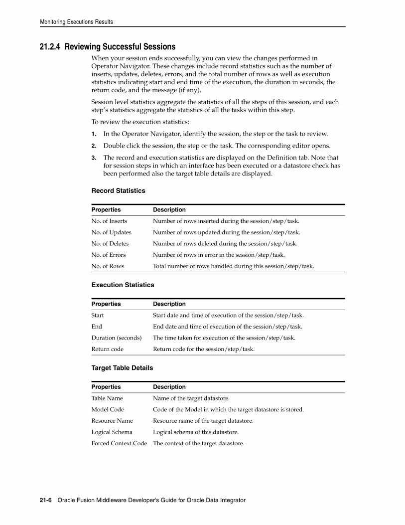
Monitoring Executions Results
21-6 Oracle Fusion Middleware Developer's Guide for Oracle Data Integrator
21.2.4 Reviewing Successful SessionsWhen your session ends successfully, you can view the changes performed in Operator Navigator. These changes include record statistics such as the number of inserts, updates, deletes, errors, and the total number of rows as well as execution statistics indicating start and end time of the execution, the duration in seconds, the return code, and the message (if any).
Session level statistics aggregate the statistics of all the steps of this session, and each step’s statistics aggregate the statistics of all the tasks within this step.
To review the execution statistics:
1. In the Operator Navigator, identify the session, the step or the task to review.
2. Double click the session, the step or the task. The corresponding editor opens.
3. The record and execution statistics are displayed on the Definition tab. Note that for session steps in which an interface has been executed or a datastore check has been performed also the target table details are displayed.
Record Statistics
Execution Statistics
Target Table Details
Properties Description
No. of Inserts Number of rows inserted during the session/step/task.
No. of Updates Number of rows updated during the session/step/task.
No. of Deletes Number of rows deleted during the session/step/task.
No. of Errors Number of rows in error in the session/step/task.
No. of Rows Total number of rows handled during this session/step/task.
Properties Description
Start Start date and time of execution of the session/step/task.
End End date and time of execution of the session/step/task.
Duration (seconds) The time taken for execution of the session/step/task.
Return code Return code for the session/step/task.
Properties Description
Table Name Name of the target datastore.
Model Code Code of the Model in which the target datastore is stored.
Resource Name Resource name of the target datastore.
Logical Schema Logical schema of this datastore.
Forced Context Code The context of the target datastore.
Managing your Executions
Monitoring Integration Processes 21-7
21.2.5 Handling Failed Load PlansWhen a Load Plan ends in error, review the sessions that have failed and caused the Load Plan to fail. Fix the source of the session failure.
You can restart the Load Plan instance. See Section 20.7, "Restarting a Load Plan Run" for more information.
Note that it will restart depending on the Restart Type defined on its steps. See Section 14.2.4, "Handling Load Plan Exceptions and Restartability" for more information.
21.2.6 Reviewing Successful Load PlansWhen your Load Plan ends successfully, you can review the execution statistics from the Load Plan run editor.
You can also review the statistics for each session started for this Load Plan in the session editor.
To review the Load Plan run execution statistics:
1. In the Operator Navigator, identify the Load Plan run to review.
2. Double click the Load Plan run. The corresponding editor opens.
3. The record and execution statistics are displayed on the Steps tab.
21.3 Managing your ExecutionsManaging your development executions takes place in Operator Navigator. You can manage your executions during the execution process itself or once the execution has finished depending on the action that you wish to perform. The actions that you can perform are:
■ Managing Sessions
■ Managing Load Plan Executions
■ Managing the Log
■ Managing Scenarios and Load Plans
■ Managing Schedules
21.3.1 Managing SessionsManaging sessions involves the following tasks
■ New sessions can be created by executing run-time objects or scenarios. See Chapter 20, "Running Integration Processes" for more information on starting sessions.
■ Sessions in progress can be aborted. How to stop sessions is covered in Section 20.5, "Stopping a Session".
■ Sessions failed, or stopped by user action can be restarted. Restarting sessions is covered in Section 20.4, "Restarting a Session".
In addition to these tasks, it may be necessary in production to deal with stale sessions.
Managing your Executions
21-8 Oracle Fusion Middleware Developer's Guide for Oracle Data Integrator
21.3.1.1 Cleaning Stale SessionsStale sessions are sessions that are incorrectly left in a running state after an agent or repository crash.
The Agent that started a session automatically detects when this session becomes stale and changes it to Error status. You can manually request specific Agents to clean stale sessions in Operator Navigator or Topology Navigator.
To clean stale sessions manually:
1. Do one of the following:
■ From the Operator Navigator toolbar menu, select Clean Stale Sessions.
■ In Topology Navigator, from the Physical Architecture accordion, select an Agent, right-click and select Clean Stale Sessions.
The Clean Stale Sessions Dialog opens.
2. In the Clean Stale Sessions Dialog specify the criteria for cleaning stale sessions:
■ From the list, select the Agents that will clean their stale sessions.
Select Clean all Agents if you want all Agents to clean their stale sessions.
■ From the list, select the Work Repositories you want to clean.
Select Clean all Work Repositories if you want to clean stale sessions in all Work Repositories.
3. Click Clean to start the cleaning process.
21.3.2 Managing Load Plan ExecutionsManaging Load Plan Executions involves the following tasks:
■ New Load Plan Instances and Runs can be created by executing Load Plans. See Section 20.6, "Executing a Load Plan" for more information on starting Load Plans.
■ Load Plan Runs in progress can be aborted. How to stop Load Plan runs is covered in Section 20.8, "Stopping a Load Plan Run".
■ Load Plan Runs failed, or stopped by user action can be restarted. Restarting Load Plan Runs is covered in Section 20.7, "Restarting a Load Plan Run".
21.3.3 Managing the Log Oracle Data Integrator provides several solutions for managing your log data:
■ Filtering Sessions to display only certain execution sessions in Operator Navigator
■ Purging the Log to remove the information of past sessions
■ Organizing the Log with Session Folders
■ Exporting and Importing Log Data for archiving purposes
21.3.3.1 Filtering SessionsFiltering log sessions allows you to display only certain sessions in Operator Navigator, by filtering on parameters such as the user, status or duration of sessions. Sessions that do not meet the current filter are hidden from view, but they are not removed from the log.
To filter out sessions:
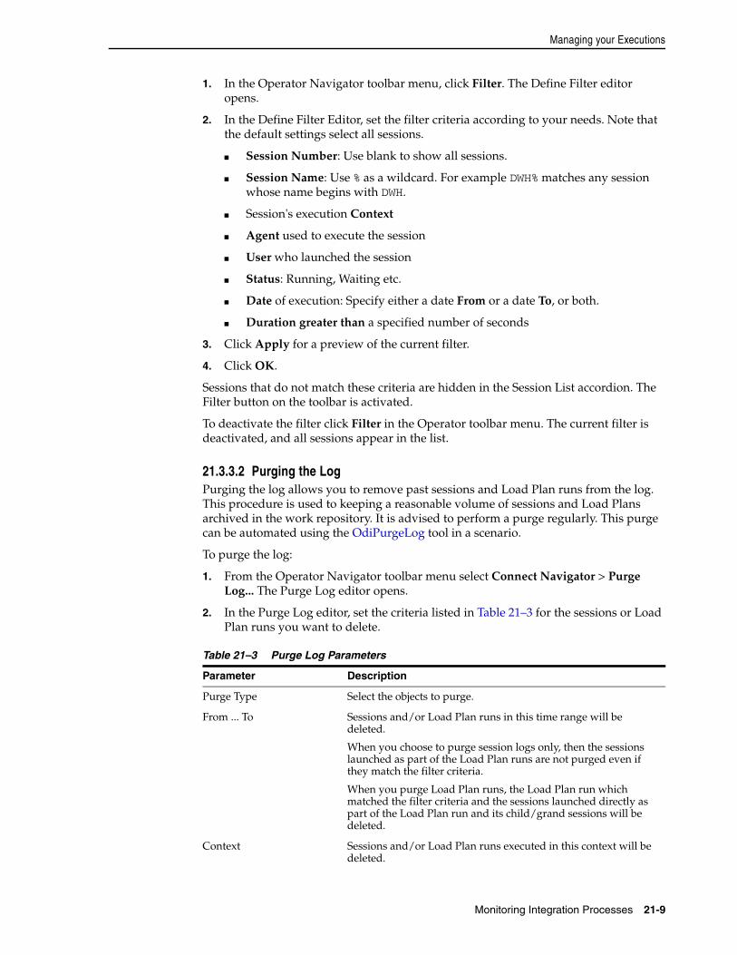
Managing your Executions
Monitoring Integration Processes 21-9
1. In the Operator Navigator toolbar menu, click Filter. The Define Filter editor opens.
2. In the Define Filter Editor, set the filter criteria according to your needs. Note that the default settings select all sessions.
■ Session Number: Use blank to show all sessions.
■ Session Name: Use % as a wildcard. For example DWH% matches any session whose name begins with DWH.
■ Session's execution Context
■ Agent used to execute the session
■ User who launched the session
■ Status: Running, Waiting etc.
■ Date of execution: Specify either a date From or a date To, or both.
■ Duration greater than a specified number of seconds
3. Click Apply for a preview of the current filter.
4. Click OK.
Sessions that do not match these criteria are hidden in the Session List accordion. The Filter button on the toolbar is activated.
To deactivate the filter click Filter in the Operator toolbar menu. The current filter is deactivated, and all sessions appear in the list.
21.3.3.2 Purging the LogPurging the log allows you to remove past sessions and Load Plan runs from the log. This procedure is used to keeping a reasonable volume of sessions and Load Plans archived in the work repository. It is advised to perform a purge regularly. This purge can be automated using the OdiPurgeLog tool in a scenario.
To purge the log:
1. From the Operator Navigator toolbar menu select Connect Navigator > Purge Log... The Purge Log editor opens.
2. In the Purge Log editor, set the criteria listed in Table 21–3 for the sessions or Load Plan runs you want to delete.
Table 21–3 Purge Log Parameters
Parameter Description
Purge Type Select the objects to purge.
From ... To Sessions and/or Load Plan runs in this time range will be deleted.
When you choose to purge session logs only, then the sessions launched as part of the Load Plan runs are not purged even if they match the filter criteria.
When you purge Load Plan runs, the Load Plan run which matched the filter criteria and the sessions launched directly as part of the Load Plan run and its child/grand sessions will be deleted.
Context Sessions and/or Load Plan runs executed in this context will be deleted.
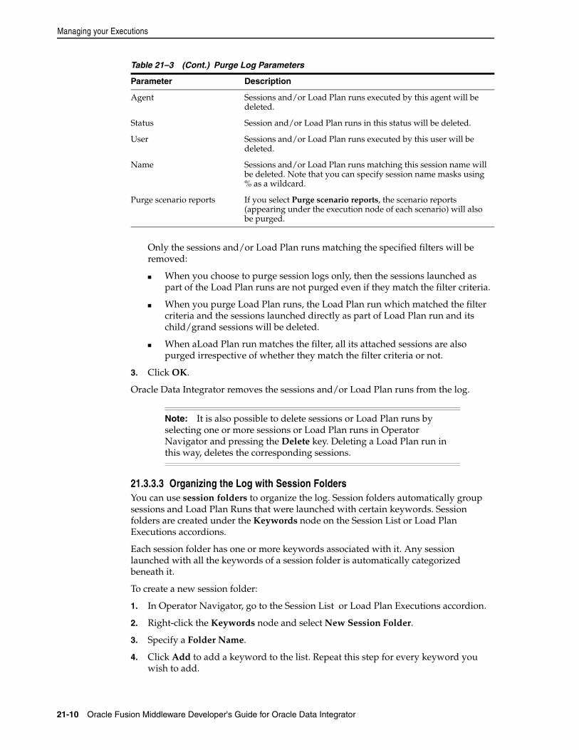
Managing your Executions
21-10 Oracle Fusion Middleware Developer's Guide for Oracle Data Integrator
Only the sessions and/or Load Plan runs matching the specified filters will be removed:
■ When you choose to purge session logs only, then the sessions launched as part of the Load Plan runs are not purged even if they match the filter criteria.
■ When you purge Load Plan runs, the Load Plan run which matched the filter criteria and the sessions launched directly as part of Load Plan run and its child/grand sessions will be deleted.
■ When aLoad Plan run matches the filter, all its attached sessions are also purged irrespective of whether they match the filter criteria or not.
3. Click OK.
Oracle Data Integrator removes the sessions and/or Load Plan runs from the log.
21.3.3.3 Organizing the Log with Session FoldersYou can use session folders to organize the log. Session folders automatically group sessions and Load Plan Runs that were launched with certain keywords. Session folders are created under the Keywords node on the Session List or Load Plan Executions accordions.
Each session folder has one or more keywords associated with it. Any session launched with all the keywords of a session folder is automatically categorized beneath it.
To create a new session folder:
1. In Operator Navigator, go to the Session List or Load Plan Executions accordion.
2. Right-click the Keywords node and select New Session Folder.
3. Specify a Folder Name.
4. Click Add to add a keyword to the list. Repeat this step for every keyword you wish to add.
Agent Sessions and/or Load Plan runs executed by this agent will be deleted.
Status Session and/or Load Plan runs in this status will be deleted.
User Sessions and/or Load Plan runs executed by this user will be deleted.
Name Sessions and/or Load Plan runs matching this session name will be deleted. Note that you can specify session name masks using % as a wildcard.
Purge scenario reports If you select Purge scenario reports, the scenario reports (appearing under the execution node of each scenario) will also be purged.
Note: It is also possible to delete sessions or Load Plan runs by selecting one or more sessions or Load Plan runs in Operator Navigator and pressing the Delete key. Deleting a Load Plan run in this way, deletes the corresponding sessions.
Table 21–3 (Cont.) Purge Log Parameters
Parameter Description
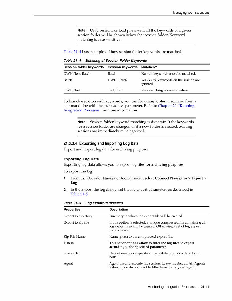
Managing your Executions
Monitoring Integration Processes 21-11
Table 21–4 lists examples of how session folder keywords are matched.
To launch a session with keywords, you can for example start a scenario from a command line with the -KEYWORDS parameter. Refer to Chapter 20, "Running Integration Processes" for more information.
21.3.3.4 Exporting and Importing Log DataExport and import log data for archiving purposes.
Exporting Log DataExporting log data allows you to export log files for archiving purposes.
To export the log:
1. From the Operator Navigator toolbar menu select Connect Navigator > Export > Log
2. In the Export the log dialog, set the log export parameters as described in Table 21–5.
Note: Only sessions or load plans with all the keywords of a given session folder will be shown below that session folder. Keyword matching is case sensitive.
Table 21–4 Matching of Session Folder Keywords
Session folder keywords Session keywords Matches?
DWH, Test, Batch Batch No - all keywords must be matched.
Batch DWH, Batch Yes - extra keywords on the session are ignored.
DWH, Test Test, dwh No - matching is case-sensitive.
Note: Session folder keyword matching is dynamic. If the keywords for a session folder are changed or if a new folder is created, existing sessions are immediately re-categorized.
Table 21–5 Log Export Parameters
Properties Description
Export to directory Directory in which the export file will be created.
Export to zip file If this option is selected, a unique compressed file containing all log export files will be created. Otherwise, a set of log export files is created.
Zip File Name Name given to the compressed export file.
Filters This set of options allow to filter the log files to export according to the specified parameters.
From / To Date of execution: specify either a date From or a date To, or both.
Agent Agent used to execute the session. Leave the default All Agents value, if you do not want to filter based on a given agent.
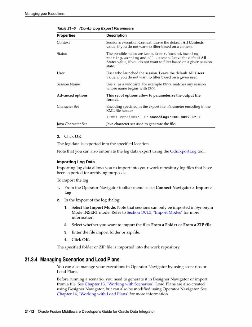
Managing your Executions
21-12 Oracle Fusion Middleware Developer's Guide for Oracle Data Integrator
3. Click OK.
The log data is exported into the specified location.
Note that you can also automate the log data export using the OdiExportLog tool.
Importing Log DataImporting log data allows you to import into your work repository log files that have been exported for archiving purposes.
To import the log:
1. From the Operator Navigator toolbar menu select Connect Navigator > Import > Log
2. In the Import of the log dialog:
1. Select the Import Mode. Note that sessions can only be imported in Synonym Mode INSERT mode. Refer to Section 19.1.3, "Import Modes" for more information.
2. Select whether you want to import the files From a Folder or From a ZIP file.
3. Enter the file import folder or zip file.
4. Click OK.
The specified folder or ZIP file is imported into the work repository.
21.3.4 Managing Scenarios and Load PlansYou can also manage your executions in Operator Navigator by using scenarios or Load Plans.
Before running a scenario, you need to generate it in Designer Navigator or import from a file. See Chapter 13, "Working with Scenarios". Load Plans are also created using Designer Navigator, but can also be modified using Operator Navigator. See Chapter 14, "Working with Load Plans" for more information.
Context Session's execution Context. Leave the default All Contexts value, if you do not want to filter based on a context.
Status The possible states are Done, Error, Queued, Running, Waiting, Warning and All States. Leave the default All States value, if you do not want to filter based on a given session state.
User User who launched the session. Leave the default All Users value, if you do not want to filter based on a given user.
Session Name Use % as a wildcard. For example DWH% matches any session whose name begins with DWH.
Advanced options This set of options allow to parameterize the output file format.
Character Set Encoding specified in the export file. Parameter encoding in the XML file header.
<?xml version="1.0" encoding="ISO-8859-1"?>
Java Character Set Java character set used to generate the file.
Table 21–5 (Cont.) Log Export Parameters
Properties Description
Managing your Executions
Monitoring Integration Processes 21-13
Launching a scenario from Operator Navigator is covered in Section 20.3.1, "Executing a Scenario from ODI Studio" and how to run a Load Plan is described in Section 20.6, "Executing a Load Plan".
21.3.4.1 Load Plan and Scenario FoldersIn Operator Navigator, scenarios and Load Plans can be grouped into Load Plan and Scenario folders to facilitate organization. Load Plan and Scenario folders can contain other Load Plan and Scenario folders.
To create a Load Plan and Scenario folder:
1. In Operator Navigator go to the Load Plans and Scenarios accordion.
2. From the Load Plans and Scenarios toolbar menu, select New Load Plan and Scenario Folder.
3. On the Definition tab of the Load Plan and Scenario Folder editor enter a name for your folder.
4. From the File menu, select Save.
You can now reorganize your scenarios and Load Plans. Drag and drop them into the Load Plan and Scenario folder.
21.3.4.2 Importing Load Plans, Scenarios, and Solutions in ProductionA Load Plan or a scenario generated from Designer can be exported and then imported into a development or execution repository. This operation is used to deploy Load Plans and scenarios in a different repository, possibly in a different environment or site.
Importing a Load Plan or scenario in a development repository is performed via Designer or Operator Navigator. With a execution repository, only Operator Navigator is available for this purpose.
See Section 13.6, "Importing Scenarios in Production" for more information on how to import a scenario in production and Section 14.4.3.2, "Importing Load Plans" for more information on the Load Plan import.
Similarly, a solution containing several scenarios can be imported to easily transfer and restore a group of scenarios at once. See Chapter 18, "Working with Version Management" for more information. Note that when connected to an execution repository, only scenarios may be restored from solutions.
21.3.5 Managing SchedulesA schedule is always attached to one scenario or one Load Plan. Schedules can be created in Operator Navigator. See Section 20.9, "Scheduling Scenarios and Load Plans" for more information.
You can also import an already existing schedule along with a scenario or Load Plan import. See Section 13.6, "Importing Scenarios in Production" and Section 14.4.3, "Exporting, Importing and Versioning Load Plans"for more information.
You can view the scheduled tasks of all your agents or you can view the scheduled tasks of one particular agent. See Section 20.9.1.3, "Displaying the Schedule" for more information.

Managing your Executions
21-14 Oracle Fusion Middleware Developer's Guide for Oracle Data Integrator
22
Working with Oracle Data Integrator Console 22-1
22Working with Oracle Data Integrator Console
This chapter describes how to work with Oracle Data Integrator Console. An overview of the Console user interface is provided.
This chapter includes the following sections:
■ Section 22.1, "Introduction to Oracle Data Integrator Console"
■ Section 22.2, "Using Oracle Data Integrator Console"
22.1 Introduction to Oracle Data Integrator ConsoleOracle Data Integrator Console is a web-based console for managing and monitoring an Oracle Data Integrator run-time architecture and for browsing design-time objects.
This section contains the following topics:
■ Introduction to Oracle Data Integrator Console
■ Oracle Data Integrator Console Interface
22.1.1 Introduction to Oracle Data Integrator ConsoleOracle Data Integrator Console is a web-based console available for different types of users:
■ Administrators use Oracle Data Integrator Console to create and import repositories and to configure the Topology (data servers, schemas, and so forth).
■ Production operators use Oracle Data Integrator Console to manage scenarios and Load Plans, monitor sessions and Load Plan runs, and manage the content of the error tables generated by Oracle Data Integrator.
■ Business users and developers browse development artifacts in this interface, using, for example, the Data Lineage and Flow Map features.
This web interface integrates seamlessly with Oracle Fusion Middleware Control Console and allows Fusion Middleware administrators to drill down into the details of Oracle Data Integrator components and sessions.
Note: Oracle Data Integrator Console is required for the Fusion Middleware Control Extension for Oracle Data Integrator. It must be installed and configured for this extension to discover and display the Oracle Data Integrator components in a domain.
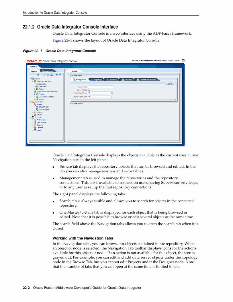
Introduction to Oracle Data Integrator Console
22-2 Oracle Fusion Middleware Developer's Guide for Oracle Data Integrator
22.1.2 Oracle Data Integrator Console InterfaceOracle Data Integrator Console is a web interface using the ADF-Faces framework.
Figure 22–1 shows the layout of Oracle Data Integrator Console.
Figure 22–1 Oracle Data Integrator Console
Oracle Data Integrator Console displays the objects available to the current user in two Navigation tabs in the left panel:
■ Browse tab displays the repository objects that can be browsed and edited. In this tab you can also manage sessions and error tables.
■ Management tab is used to manage the repositories and the repository connections. This tab is available to connection users having Supervisor privileges, or to any user to set up the first repository connections.
The right panel displays the following tabs:
■ Search tab is always visible and allows you to search for objects in the connected repository.
■ One Master/Details tab is displayed for each object that is being browsed or edited. Note that it is possible to browse or edit several objects at the same time.
The search field above the Navigation tabs allows you to open the search tab when it is closed.
Working with the Navigation TabsIn the Navigation tabs, you can browse for objects contained in the repository. When an object or node is selected, the Navigation Tab toolbar displays icons for the actions available for this object or node. If an action is not available for this object, the icon is grayed out. For example, you can edit and add data server objects under the Topology node in the Browse Tab, but you cannot edit Projects under the Designer node. Note that the number of tabs that you can open at the same time is limited to ten.
Using Oracle Data Integrator Console
Working with Oracle Data Integrator Console 22-3
22.2 Using Oracle Data Integrator ConsoleThis section explains the different types of operations available in Oracle Data Integrator console. It does not focus on each type of object that can be managed with the console, but gives keys to manage objects with the console.
This section includes the following topics:
■ Connecting to Oracle Data Integrator Console
■ Generic User Operations
■ Managing Scenarios and Sessions
■ Managing Load Plans
■ Purging the Log
■ Using Data Lineage and Flow Map
■ Performing Administrative Operations
22.2.1 Connecting to Oracle Data Integrator ConsoleOracle Data Integrator console connects to a repository via a Repository Connection, defined by an administrator.
Note that you can only connect to Oracle Data Integrator Console if it has been previously installed. See the Oracle Fusion Middleware Installation Guide for Oracle Data Integrator for more information about installing Oracle Data Integrator Console.
Connecting to Oracle Data Integrator ConsoleTo connect to Oracle Data Integrator Console:
1. Open a web browser, and connect to the URL where Oracle Data Integrator Console is installed. For example: http://odi_host:8001/odiconsole/.
2. From the Repository list, select the Repository connection corresponding to the master or work repository you want to connect.
3. Provide a User ID and a Password.
4. Click Sign In.
Note: Oracle Data Integrator Console uses the security defined in the master repository. Operations that are not allowed for a user will appear grayed out for this user.
In addition, the Management tab is available only for users with Supervisor privileges.
Note: The first time you connect to Oracle Data Integrator Console, if no repository connection is configured, you will have access to the Management tab to create a first repository connection. See "Creating a Repository Connection" for more information. After your first repository connection is created, the Management tab is no longer available from the Login page, and is available only for users with Supervisor privileges.
Using Oracle Data Integrator Console
22-4 Oracle Fusion Middleware Developer's Guide for Oracle Data Integrator
22.2.2 Generic User OperationsThis section describes the generic operations available in Oracle Data Integrator Console for a typical user.
This section includes the following operations:
■ Viewing an Object
■ Editing an Object
■ Creating an Object
■ Deleting an Object
■ Searching for an Object
Viewing an ObjectTo view an object:
1. Select the object in the Browse or Management Navigation tab.
2. Click View in the Navigation tab toolbar. The simple page or the Master/Detail page for the object opens.
Editing an ObjectTo edit an object:
1. Select the object in the Browse or Management Navigation tab.
2. Click Update in the Navigation tab toolbar. The edition page for the object opens.
3. Change the value for the object fields.
4. Click Save in the edition page for this object.
Creating an ObjectTo create an object:
1. Navigate to the parent node of the object you want to create in the Browse or Management Navigation tab. For example, to create a Context, navigate to the Topology > Contexts node in the Browse tab.
2. Click Create in the Navigation tab toolbar. An Add dialog for this object appears.
3. Provide the values for the object fields.
4. Click Save in the Add dialog of this object. The new object appears in the Navigation tab.
Deleting an ObjectTo delete an object:
1. Select the object in the Browse or Management Navigation tab.
2. Click Delete in the Navigation tab toolbar.
Note: Creating, editing, and deleting operations are not allowed for Scenarios and Load Plans. For more information on the possible actions that can be performed with these objects in ODI Console, see Section 22.2.3, "Managing Scenarios and Sessions" and Section 22.2.4, "Managing Load Plans".
Using Oracle Data Integrator Console
Working with Oracle Data Integrator Console 22-5
3. Click OK in the confirmation window.
Searching for an ObjectTo search for an object:
1. In the Search tab, select the tab corresponding to the object you want to search:
■ Design Time tab allows you to search for design-time objects
■ Topology tab allows you to search for topology objects
■ Runtime tab allows you to search for run-time objects such as Load Plans, Scenarios, Scenario Folders, or Session Folders
■ Sessions tab allows you to search for sessions
■ Load Plan Execution tab allows you to search for Load Plan runs
2. Set the search parameters to narrow your search.
For example when searching design-time or topology objects:
1. In the Search Text field, enter a part of the name of the object that you want to search.
2. Select Case sensitive if you want the search to be case sensitive (this feature is not provided for the sessions or Load Plan execution search.
3. Select in Models/Project (Designer tab) or Topology (Topology tab) the type of object you want to search for. Select All to search for all objects.
3. Click Search.
4. The Search Results appear, grouped by object type. You can click an object in the search result to open its master/details page.
22.2.3 Managing Scenarios and SessionsThis section describes the operations related to scenarios and sessions available in Oracle Data Integrator Console.
This section includes the following operations:
■ Importing a Scenario
■ Exporting a Scenario
■ Running a Scenario
■ Stopping a Session
■ Restarting a Session
■ Cleaning Stale Sessions
■ Managing Data Statistics and Erroneous Records
Importing a ScenarioTo import a scenario:
1. Select the Browse Navigation tab.
2. Navigate to Runtime > Scenarios/Load Plans > Scenarios.
3. Click Import in the Navigation tab toolbar.
4. Select an Import Mode and select an export file in Scenario XML File.
Using Oracle Data Integrator Console
22-6 Oracle Fusion Middleware Developer's Guide for Oracle Data Integrator
5. Click Import Scenario.
Exporting a ScenarioTo export a scenario:
1. Select the Browse Navigation tab.
2. Navigate to Runtime > Scenarios/Load Plans > Scenarios.
3. Click Export in the Navigation tab toolbar.
4. In the Export Scenario dialog, set the parameters as follows:
■ From the Scenario Name list, select the scenario to export.
■ In the Encoding Java Charset field, enter the Java character set for the export file.
■ In the Encoding XML Charset field, enter the encoding to specify in the export file.
■ In the XML Version field, enter the XML Version to specify in the export file.
■ Optionally, select Include Dependant objects to export linked child objects.
5. Click Export Scenario.
Running a ScenarioTo execute a scenario:
1. Select the Browse Navigation tab.
2. Navigate to Runtime > Scenarios/Load Plans > Scenarios.
3. Select the scenario you want to execute.
4. Click Execute in the Navigation tab toolbar.
5. Select an Agent, a Context, and a Log Level for this execution.
6. Click Execute Scenario.
Stopping a SessionNote that you can perform a normal or an immediate kill of a running session. Sessions with the status Done, Warning, or Error cannot be killed.
To kill a session:
1. Select the Browse Navigation tab.
2. Navigate to Runtime > Sessions/Load Plan Executions > Sessions.
3. Select the session you want to stop.
4. Click Kill in the Navigation tab toolbar.
Restarting a SessionTo restart a session:
1. Select the Browse Navigation tab.
2. Navigate to Runtime > Sessions/Load Plan Executions > Sessions.
3. Select the session you want to restart.
4. Click Restart in the Navigation tab toolbar.
Using Oracle Data Integrator Console
Working with Oracle Data Integrator Console 22-7
Cleaning Stale SessionsTo clean stale sessions:
1. Select the Browse Navigation tab.
2. Navigate to Runtime > Sessions/Load Plan Executions > Sessions.
3. Click Clean in the Navigation tab toolbar.
4. In the Clean Stale Sessions dialog, select the Agent for which you want to clean stale sessions.
5. Click OK.
Managing Data Statistics and Erroneous RecordsOracle Data Integrator Console allows you to browse the details of a session, including the record statistics. When a session detects erroneous data during a flow or static check, these errors are isolated into error tables. You can also browse and manage the erroneous rows using Oracle Data Integrator Console.
To view the erroneous data:
1. Select the Browse Navigation tab.
2. Navigate to a given session using Runtime > Sessions/Load Plan Executions > Sessions. Select the session and click View in the Navigation tab toolbar.
The Session page is displayed.
3. In the Session page, go to the Relationships section and select the Record Statistics tab.
This tab shows each physical table targeting in this session, as well as the record statistics.
4. Click the number shown in the Errors column. The content of the error table appears.
■ You can filter the errors by Constraint Type, Name, Message Content, Detection date, and so forth. Click Filter Result to apply a filter.
■ Select a number of errors in the Query Results table and click Delete to delete these records.
■ Click Delete All to delete all the errors.
22.2.4 Managing Load PlansThis section describes the operations related to Load Plans available in Oracle Data Integrator Console.
This section includes the following operations:
■ Importing a Load Plan
■ Exporting a Load Plan
Note: Sessions with erroneous data detected finish in Warning status.
Note: Delete operations cannot be undone.

Using Oracle Data Integrator Console
22-8 Oracle Fusion Middleware Developer's Guide for Oracle Data Integrator
■ Running a Load Plan
■ Stopping a Load Plan Run
■ Restarting a Load Plan Run
Importing a Load PlanTo import a Load Plan:
1. Select the Browse Navigation tab.
2. Navigate to Runtime > Scenarios/Load Plans > Load Plans.
3. Click Import in the Navigation tab toolbar.
4. In the Import Load Plan dialog, select an Import Mode and select an export file in the Select Load Plan XML File field.
5. Click Import.
Exporting a Load PlanTo export a Load Plan:
1. Select the Browse Navigation tab.
2. Navigate to Runtime > Scenarios/Load Plans > Load Plans.
3. Select the Load Plan to export.
4. Click Export in the Navigation tab toolbar.
5. In the Export dialog, set the parameters as follows:
■ From the Load Plan Name list, select the Load Plan to export.
■ In the Encoding Java Charset field, enter the Java character set for the export file.
■ In the Encoding XML Charset field, enter the encoding to specify in the export file.
■ In the XML Version field, enter the XML Version to specify in the export file.
■ Optionally, select Include Dependant objects to export linked child objects.
6. Click Export.
Running a Load PlanTo run a Load Plan:
1. Select the Browse Navigation tab.
2. Navigate to Runtime > Scenarios/Load Plans > Load Plans.
Note: When you import a Load Plan that has been previously exported, the imported Load Plan does not include the scenarios referenced by the Load Plan. Scenarios used in a Load Plan need to be imported separately. See Importing a Scenario for more information.
Note: The export of a Load Plan does not include the scenarios referenced by the Load Plan. Scenarios used in a Load Plan need to be exported separately. See Exporting a Scenario for more information.
Using Oracle Data Integrator Console
Working with Oracle Data Integrator Console 22-9
3. Select the Load Plan you want to execute.
4. Click Execute in the Navigation tab toolbar.
5. Select a Logical Agent, a Context, and if your Load Plan uses variables, specify the Startup values for the Load Plan variables.
6. Click Execute.
Stopping a Load Plan RunNote that you can perform a normal or an immediate kill of a Load Plan run. Any running or waiting Load Plan Run can be stopped.
To stop a Load Plan Run:
1. Select the Browse Navigation tab.
2. Navigate to Runtime > Sessions/Load Plan Executions > Load Plan Executions.
3. Select the Load Plan run you want to stop.
4. Click Kill in the Navigation tab toolbar.
Restarting a Load Plan RunA Load Plan can only be restarted if the selected run of the current Load Plan instance is in Error status and if there is no other instance of the same Load Plan currently running.
To restart a Load Plan Run:
1. Select the Browse Navigation tab.
2. Navigate to Runtime > Sessions/Load Plan Executions > Load Plan Executions.
3. Select the Load Plan run you want to restart.
4. Click Restart in the Navigation tab toolbar.
22.2.5 Purging the LogThis section describes how to purge the log in Oracle Data Integrator Console by removing past sessions and/or Load Plan runs from the log.
To purge the log:
1. Select the Browse Navigation tab.
2. Navigate to Runtime > Sessions/Load Plan Executions.
3. Click Purge in the Navigation tab toolbar.
4. In the Purge Sessions/Load Plan Executions dialog, set the purge parameters listed in Table 22–1.
Table 22–1 Purge Log Parameters
Parameter Description
Purge Type Select the objects to purge.
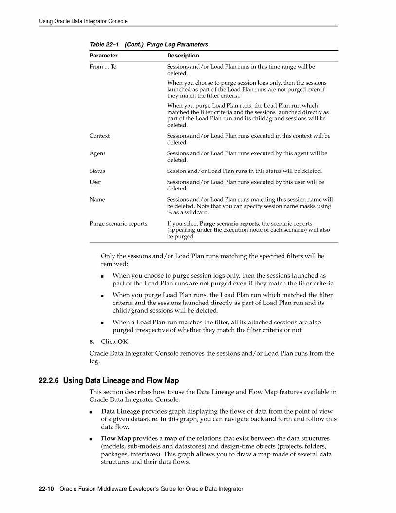
Using Oracle Data Integrator Console
22-10 Oracle Fusion Middleware Developer's Guide for Oracle Data Integrator
Only the sessions and/or Load Plan runs matching the specified filters will be removed:
■ When you choose to purge session logs only, then the sessions launched as part of the Load Plan runs are not purged even if they match the filter criteria.
■ When you purge Load Plan runs, the Load Plan run which matched the filter criteria and the sessions launched directly as part of Load Plan run and its child/grand sessions will be deleted.
■ When a Load Plan run matches the filter, all its attached sessions are also purged irrespective of whether they match the filter criteria or not.
5. Click OK.
Oracle Data Integrator Console removes the sessions and/or Load Plan runs from the log.
22.2.6 Using Data Lineage and Flow MapThis section describes how to use the Data Lineage and Flow Map features available in Oracle Data Integrator Console.
■ Data Lineage provides graph displaying the flows of data from the point of view of a given datastore. In this graph, you can navigate back and forth and follow this data flow.
■ Flow Map provides a map of the relations that exist between the data structures (models, sub-models and datastores) and design-time objects (projects, folders, packages, interfaces). This graph allows you to draw a map made of several data structures and their data flows.
From ... To Sessions and/or Load Plan runs in this time range will be deleted.
When you choose to purge session logs only, then the sessions launched as part of the Load Plan runs are not purged even if they match the filter criteria.
When you purge Load Plan runs, the Load Plan run which matched the filter criteria and the sessions launched directly as part of the Load Plan run and its child/grand sessions will be deleted.
Context Sessions and/or Load Plan runs executed in this context will be deleted.
Agent Sessions and/or Load Plan runs executed by this agent will be deleted.
Status Session and/or Load Plan runs in this status will be deleted.
User Sessions and/or Load Plan runs executed by this user will be deleted.
Name Sessions and/or Load Plan runs matching this session name will be deleted. Note that you can specify session name masks using % as a wildcard.
Purge scenario reports If you select Purge scenario reports, the scenario reports (appearing under the execution node of each scenario) will also be purged.
Table 22–1 (Cont.) Purge Log Parameters
Parameter Description
Using Oracle Data Integrator Console
Working with Oracle Data Integrator Console 22-11
This section includes the following operations:
■ Working with the Data Lineage
■ Working with the Flow Map
Working with the Data LineageTo view the Data Lineage:
1. Select the Browse Navigation tab.
2. Navigate to Design Time > Models > Data Lineage.
3. Click View in the Navigation tab toolbar.
4. In the Data Lineage page, select a Model, then a Sub-Model and a datastore in this model.
5. Select Show Interfaces if you want that interfaces are displayed between the datastores nodes.
6. Select the prefix to add in your datastores and interface names in the Naming Options section.
7. Click View to draw the Data Lineage graph. This graph is centered on the datastore selected in step 4.
In this graph, you can use the following actions:
■ Click Go Back to return to the Data Lineage options and redraw the graph.
■ Use the Hand tool and then click a datastore to redraw the lineage centered on this datastore.
■ Use the Hand tool and then click an interface to view this interface’s page.
■ Use the Arrow tool to expand/collapse groups.
■ Use the Move tool to move the graph.
■ Use the Zoom In/Zoom Out tools to resize the graph.
■ Select View Options to change the display options have the graph refreshed with this new option.
Working with the Flow MapTo view the Flow Map:
1. Select the Browse Navigation tab.
2. Navigate to Design Time > Models > Flow Map.
3. Click View in the Navigation tab toolbar.
4. In the Data Lineage page, select one or more Model. Select All to select all models.
5. Select one of more Projects. Select All to select all projects.
6. In the Select the level of details of the map section, select the granularity of the map. The object that you select here will be the nodes of your graph.
Check Do not show Projects, Folders... if you want the map to show only data structure.
7. Optionally, indicate the grouping for the data structures and design-time objects in the map, using the options in the Indicate how to group Objects in the Map section.
Using Oracle Data Integrator Console
22-12 Oracle Fusion Middleware Developer's Guide for Oracle Data Integrator
8. Click View to draw the Flow Map graph.
In this graph, you can use the following actions:
■ Click Go Back to return to the Flow Map options and redraw the graph.
■ Use the Hand tool and then click a node (representing a datastore, an interface, and so forth) in the map to open this object’s page.
■ Use the Arrow tool to expand/collapse groups.
■ Use the Move tool to move the graph.
■ Use the Zoom In/Zoom Out tools to resize the graph.
22.2.7 Performing Administrative OperationsThis section describes the different administrative operations available in Oracle Data Integrator Console. These operations are available for a user with Supervisor privileges.
This section includes the following operations:
■ Creating a Repository Connection
■ Testing a Data Server or a Physical Agent Connection
■ Administering Repositories
■ Administering Java EE Agents
Creating a Repository ConnectionA repository connection is a connection definition for Oracle Data Integrator Console. A connection does not include Oracle Data Integrator user and password information.
To create a repository connection:
1. Navigate to the Repository Connections node in the Management Navigation tab.
2. Click Create in the Navigation tab toolbar. A Create Repository Connection dialog for this object appears.
3. Provide the values for the repository connection:
■ Connection Alias: Name of the connection that will appear on the Login page.
■ Master JNDI URL: JNDI URL of the datasource to connect the master repository database.
■ Supervisor User Name: Name of the Oracle Data Integrator user with Supervisor privileges that Oracle Data Integrator Console will use to connect to the repository. This user’s password must be declared in the WLS Credential Store.
■ Work JNDI URL: JNDI URL of the datasource to connect the work repository database. If no value is given in this field. The repository connection will allow connection to the master only, and the Navigation will be limited to Topology information.
■ JNDI URL: Check this option if you want to use the environment naming context (ENC). When this option is checked, Oracle Data Integrator Console automatically prefixes the data source name with the string java:comp/env/ to identify it in the application server’s JNDI directory.
Using Oracle Data Integrator Console
Working with Oracle Data Integrator Console 22-13
Note that the JNDI Standard is not supported by Oracle WebLogic Server and for global data sources.
■ Default: Check this option if you want this Repository Connection to be selected by default on the login page.
4. Click Save. The new Repository Connection appears in the Management Navigation tab.
Testing a Data Server or a Physical Agent ConnectionThis sections describes how to test the data server connection or the connection of a physical agent in Oracle Data Integrator Console.
To test the data server connection:
1. Select the Browse Navigation tab.
2. Navigate to Topology > Data Servers.
3. Select the data server whose connection you want to test.
4. Click Test Connection in the Navigation tab toolbar.
5. In the Test Connection dialog, select the:
■ Physical Agent that will carry out the test
■ Transaction on which you want to execute the command. This parameter is only displayed if there is any On Connect/Disconnect command defined for this data server. The transactions from 0 to 9 and the Autocommit transaction correspond to connection created by sessions (by procedures or knowledge modules). The Client Transaction corresponds to the client components (ODI Console and Studio).
6. Click Test.
A dialog showing "Connection successful!" is displayed if the test has worked. If not, an error message is displayed.
To test the physical agent connection:
1. Select the Browse Navigation tab.
2. Navigate to Topology > Agents > Physical Agents.
3. Select the physical agent whose connection you want to test.
4. Click Test Connection in the Navigation tab toolbar.
A dialog showing "Connection successful!" is displayed if the test has worked. If not, an error message is displayed.
Administering RepositoriesOracle Data Integrator Console provides you with features to perform management operations (create, import, export) on repositories. These operations are available from the Management Navigation tab, under the Repositories node. These management operations reproduce in a web interface the administrative operations available via the Oracle Data Integrator Studio and allow setting up and maintaining your environment from the ODI Console.
See Chapter 3, "Administering the Oracle Data Integrator Repositories" and Chapter 19, "Exporting/Importing" for more information on these operations.
Using Oracle Data Integrator Console
22-14 Oracle Fusion Middleware Developer's Guide for Oracle Data Integrator
Administering Java EE AgentsOracle Data Integrator Console allows you to add JDBC datasources and create templates to deploy physical agents into WebLogic Server.
See Chapter 4, "Setting-up the Topology" for more information on Java EE Agents, datasources and templates.
To add a datasource to a physical agent:
1. Select the Browse Navigation tab.
2. Navigate to Topology > Agents > Physical Agents.
3. Select the agent you want to manage.
4. Click Edit in the Navigation tab toolbar.
5. Click Add Datasource
6. Provide a JNDI Name for this datasource and select the Data Server Name. This datasource will be used to connect to this data server from the machine into which the Java EE Agent will be deployed.
7. Click OK.
8. Click Save to save the changes to the physical agent.
To create a template for a physical agent:
1. Select the Browse Navigation tab.
2. Navigate to Topology > Agents > Physical Agents.
3. Select the agent you want to manage.
4. Click Edit in the Navigation tab toolbar.
5. Click Agent Deployment.
6. Follow the steps of the Agent Deployment wizard. This wizard reproduces in a web interface the WLS Template Generation wizard. See Chapter 4.3.2.1, "Deploying an Agent in a Java EE Application Server (Oracle WebLogic Server)" for more details.
Part VIIPart VII Managing the Security Settings
This part describes how to manage the security settings in Oracle Data Integrator.
This part contains the following chapters:
■ Chapter 23, "Managing the Security in Oracle Data Integrator"

23
Managing the Security in Oracle Data Integrator 23-1
23Managing the Security in Oracle DataIntegrator
This chapter describes how to set up security in Oracle Data Integrator. An overview of Oracle Data Integrator security concepts and components is provided.
This chapter contains the following sections:
■ Section 23.1, "Introduction to Oracle Data Integrator Security"
■ Section 23.2, "Setting up a Security Policy"
■ Section 23.3, "Advanced Security"
23.1 Introduction to Oracle Data Integrator SecurityOracle Data Integrator security is used to secure any action performed by authenticated users against the design-time and run-time artifacts and components of Oracle Data Integrator.
Security is built around users and profiles, to which security administrators grant methods (edit, delete, and so forth) on objects types (projects, models, interfaces, and so forth) or on specific object instances (Data warehouse Project, ODS Project, and so forth).
All the security information for Oracle Data Integrator is stored in the master repository.
This section contains the following topics:
■ Section 23.1.1, "Objects, Instances and Methods"
■ Section 23.1.2, "Profiles"
■ Section 23.1.3, "Users"
23.1.1 Objects, Instances and MethodsAn Object is a representation of a design-time or run-time artifact handled through Oracle Data Integrator. For example, agents, models, datastores, scenarios, interfaces and even repositories are objects. Specific objects have a double name (Agent/Context, Profile/Method, and so forth). These objects represent links between objects. These links are also objects. For instance, Agent/Context corresponds to a physical/logical agent association made through the contexts. Privileges on this object enable to change this association in the topology.
An Instance is a particular occurrence of an object. For example, the Datawarehouse project is an instance of the Project object.
Introduction to Oracle Data Integrator Security
23-2 Oracle Fusion Middleware Developer's Guide for Oracle Data Integrator
A Method is an action that can be performed on an object. Each object has a predefined set of methods.
23.1.2 ProfilesA Profile contains a set of privileges for working with Oracle Data Integrator. One or more profiles can be assigned to a user to grant the sum of these privileges to this user.
A Profile Method is an authorization granted to a profile on a method of an object type. Each granted method allows a user with this profile to perform an action (edit, delete, and so forth) on an instance of an object type (project, model, datastore, and so forth).
Methods granted to a profile appear under this profile in the Profiles accordion of the Security Navigator. When a method does not appear for a given profile, this profile does not have access to this method.
A method can be granted as a generic or non-generic privilege:
■ A method granted as a generic privilege is granted by default on all the instances of this object.
■ A method granted as a non-generic privilege is not granted by default on all object instances, but may be granted per instance.
Generic vs. Non-Generic profilesGeneric profiles have the Generic privilege option selected for all object methods. This implies that a user with such a profile is by default authorized for all methods of all instances of an object to which the profile is authorized.
Non-Generic profiles are not by default authorized for all methods on the instances since the Generic privilege option is not selected for all object methods. The administrator must grant the user the rights on the methods for each instance.
If the security administrator wants a user to have the rights on no instance by default, but wishes to grant the rights by instance, the user must be given a non-generic profile.
If the security administrator wants a user to have the rights on all instances of an object type by default, the user must be given a generic profile.
Built-In ProfilesOracle Data Integrator has some built-in profiles that the security administrator can assign to the users he creates.
Table 23–1 shows the built-in profiles delivered with Oracle Data Integrator.
Note: The notions of object instance and method in Oracle Data Integrator are similar to the concepts used in Object-Oriented Programming.
WARNING: Although they appear in the Security Navigator, objects and methods are predefined in Oracle Data Integrator and should not be altered.
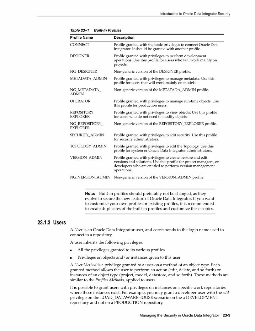
Introduction to Oracle Data Integrator Security
Managing the Security in Oracle Data Integrator 23-3
23.1.3 UsersA User is an Oracle Data Integrator user, and corresponds to the login name used to connect to a repository.
A user inherits the following privileges:
■ All the privileges granted to its various profiles
■ Privileges on objects and/or instances given to this user
A User Method is a privilege granted to a user on a method of an object type. Each granted method allows the user to perform an action (edit, delete, and so forth) on instances of an object type (project, model, datastore, and so forth). These methods are similar to the Profiles Methods, applied to users.
It is possible to grant users with privileges on instances on specific work repositories where these instances exist. For example, you may grant a developer user with the edit privilege on the LOAD_DATAWAREHOUSE scenario on the a DEVELOPMENT repository and not on a PRODUCTION repository.
Table 23–1 Built-In Profiles
Profile Name Description
CONNECT Profile granted with the basic privileges to connect Oracle Data Integrator. It should be granted with another profile.
DESIGNER Profile granted with privileges to perform development operations. Use this profile for users who will work mainly on projects.
NG_DESIGNER Non-generic version of the DESIGNER profile.
METADATA_ADMIN Profile granted with privileges to manage metadata. Use this profile for users that will work mainly on models.
NG_METADATA_ADMIN
Non-generic version of the METATADA_ADMIN profile.
OPERATOR Profile granted with privileges to manage run-time objects. Use this profile for production users.
REPOSITORY_EXPLORER
Profile granted with privileges to view objects. Use this profile for users who do not need to modify objects.
NG_REPOSITORY_EXPLORER
Non-generic version of the REPOSITORY_EXPLORER profile.
SECURITY_ADMIN Profile granted with privileges to edit security. Use this profile for security administrators.
TOPOLOGY_ADMIN Profile granted with privileges to edit the Topology. Use this profile for system or Oracle Data Integrator administrators.
VERSION_ADMIN Profile granted with privileges to create, restore and edit versions and solutions. Use this profile for project managers, or developers who are entitled to perform version management operations.
NG_VERSION_ADMIN Non-generic version of the VERSION_ADMIN profile.
Note: Built-in profiles should preferably not be changed, as they evolve to secure the new feature of Oracle Data Integrator. If you want to customize your own profiles or existing profiles, it is recommended to create duplicates of the built-in profiles and customize these copies.
Setting up a Security Policy
23-4 Oracle Fusion Middleware Developer's Guide for Oracle Data Integrator
An authorization by Object Instance is granted to a user on an object instance. It allows to grant to this user certain methods of this object instance.
The presence in a user's tree of an authorization by object instance for a given instance shows that the user is granted specific privileges on the object methods for the given instance (these privileges are specified in the Object Instance editor). If an instance is not visible in the tree of the user instances, then the User Method or Profile Method privileges for the object type apply.
As an instance may be replicated over the different work repositories that are attached to the master repository, authorizations by object instances may be defined for one, multiple or all your work repositories attached to this master repository. For example, a LOAD_DATAWAREHOUSE scenario instance may be replicated (using for example versioning) in the DEVELOPMENT, TEST, and PRODUCTION repositories. Privileges on the instance will change depending on the repository.
For example, it is common to replicate projects from a Development repository to a Test repository. A developer may be granted edit privileges for his project in the Development repository, but not on the Test repository. On the Test repository, he will only be granted with view privileges on the project.
23.2 Setting up a Security PolicyThis section explains how to use the different security concepts to enforce security in Oracle Data Integrator.
This section contains these topics:
■ Section 23.2.1, "Security Policy Approach"
■ Section 23.2.2, "Managing Profiles"
■ Section 23.2.3, "Managing Users"
■ Section 23.2.4, "Managing Privileges"
23.2.1 Security Policy ApproachThere are two main approaches for defining the security in Oracle Data Integrator:
■ The strongly secured approach, where users have no default authorizations on objects. This approach uses only non-generic profiles. The security administrator must grant the users authorizations on object instances. This policy is complex to configure, as it requires to manage privileges by instance.
■ The generic approach, where users inherit the privileges of the profiles they have. This policy is suitable for most cases, and is simple to configure.
To implement a strongly secured approach:
1. Create the users.
2. Give the users non-generic profiles (built-in or customized).
3. Grant the users privileges on object instances after these are created. This operation must be repeated for every new instance.
To implement a generic approach:
1. Create the users.
2. Give the users the generic profiles (built-in or customized).
Setting up a Security Policy
Managing the Security in Oracle Data Integrator 23-5
23.2.2 Managing ProfilesYou can create, delete or duplicate profiles to customize the profiles assigned to users.
23.2.2.1 Creating a New ProfileTo create a Profile:
1. In Security Navigator expand the Profiles accordion.
2. Click New Profile in the toolbar of the Profiles accordion.
3. In the Name field, enter a name for your profile.
4. From the File main menu, select Save.
The new profile appears.
23.2.2.2 Duplicating a ProfileTo duplicate a Profile:
1. In Security Navigator expand the Profiles accordion.
2. Select the profile that you want to duplicate from the list of profiles.
3. Right-click and select Duplicate.
A new profile (copy of the original profile) appears.
23.2.2.3 Deleting a ProfileTo delete a Profile:
1. In Security Navigator expand the Profiles accordion.
2. Select the profile that you want to delete from the list of profiles.
3. Right-click and select Delete.
4. Click OK in the Confirmation dialog.
The profile disappears from the list. All users granted with this profile lose the privileges attached to this profile.
23.2.3 Managing UsersYou can create and delete users, assign and remove built-in or customized profiles to users.
23.2.3.1 Creating a New UserTo create a User:
1. In Security Navigator expand the Users accordion.
2. Click New User in the toolbar of the Users accordion.
Note: It is possible to combine the two approaches by using simultaneously generic and non generic profiles. For example, by using DESIGNER and NG_METADATA_ADMIN for the users, you would manage projects is a generic approach and models in a strongly secured approach.
Setting up a Security Policy
23-6 Oracle Fusion Middleware Developer's Guide for Oracle Data Integrator
3. In the Name field, enter a name for your user.
4. Provide the Initials for this user.
5. Do one of the following:
■ If using Internal Authentication, click Enter the Password and provide a password for this user.
■ If using External Authentication, click Retrieve GUID to associate the new user with a user from the external authentication service. The user name in Oracle Data Integrator must match the user login in the external authentication storage. If a match is found, an Global Unique ID appears in the External GUID field.
6. From the File main menu, select Save.
The new user appears in the Users accordion.
23.2.3.2 Assigning a Profile to a UserTo assign a Profile to a User:
1. In Security Navigator expand the Users and the Profiles accordions.
2. Select the profile that you want to assign, then drag it on the user you want to assign it to.
3. Click OK in the Confirmation dialog.
The profile appears under the Profiles of this user. The user is immediately granted the privileges attached to this profile.
23.2.3.3 Removing a Profile from a UserTo remove a Profile to a User:
1. In Security Navigator expand the Users accordions.
2. Expand the Profiles node under the user.
3. Right-click the profile to be removed.
4. Select Delete.
5. Click OK in the Confirmation dialog.
The profile disappears from the Profiles of this user. All privileges granted to this user via this profile are removed.
23.2.3.4 Deleting a UserTo delete a User:
1. In Security Navigator expand the Users accordion.
2. From the list of users, select the user that you want to delete.
3. Right-click and select Delete.
4. Click OK in the Confirmation window.
The user disappears from the list.
Setting up a Security Policy
Managing the Security in Oracle Data Integrator 23-7
23.2.4 Managing PrivilegesAfter creating users or profiles, it is possible to grant privileges to these users and profiles. You can grant Profile Methods and User Methods that apply to object types, and Authorizations by Object Instances (for users only) that apply to specific object instances.
23.2.4.1 Granting a Profile Method or User MethodTo grant a Profile Method or User Method:
1. In Security Navigator expand the Users or Profiles accordion.
2. Expand the Objects accordion, and expand the node of the object for which you want to grant a privilege.
3. Select the method that you want to grant, then drag it on the user or profile you want to grant the method to.
4. Click OK in the Confirmation window.
The Method is granted to the user or the profile. It appears under the Objects node of this user or under the profile.
23.2.4.2 Revoking a Profile Method or User MethodTo revoke a Profile Method or User Method:
1. In Security Navigator expand the Users or Profiles accordion.
2. Expand the Profiles or the Objects node under the user for which you want you revoke privileges, then expand the object whose method needs to be revoked.
3. Right-click the method and then select Delete.
4. Click OK in the Confirmation dialog.
The Method is revoked from the user or the profile. It disappears from the methods list under the Objects node of this user or profile.
23.2.4.3 Granting an Authorization by Object InstanceTo grant an authorization by object instance to a user:
1. In Security Navigator expand the Users accordion.
2. In the Designer, Operator or Topology Navigator, expand the accordion containing the object onto which you want to grant privileges.
3. Select this object, then drag it on the user in the Users accordion. The authorization by object instance editor appears. This editor shows the list of methods available for this instance and the instances contained into it. For example, if you grant privileges on a project instance, the folders, interfaces, and so forth contained in this project will appear in the editor.
4. Fine-tune the privileges granted per object and method. You may want to implement the following simple privileges policies on methods that you select from the list:
■ To grant all these methods in all repositories, click Allow selected methods in all repositories.
Note: You can grant privileges on all the methods of an object by dragging the object itself on the user or profile instead of dragging one of its methods.
Setting up a Security Policy
23-8 Oracle Fusion Middleware Developer's Guide for Oracle Data Integrator
■ To deny all these methods in all repositories, click Deny selected methods in all repositories.
■ To grant all these methods in certain work repositories, click Allow selected methods in selected repositories, then select the repositories from the list.
5. From the File main menu, select Save.
23.2.4.4 Revoking an Authorization by Object InstanceTo revoke an authorization by object instance from an user:
1. In Security Navigator expand the Users accordion.
2. Expand the Instances node under the user for which you want you revoke privileges.
3. Right-click the instance from which you want to revoke an authorization, and then select Delete.
4. Click OK in the Confirmation dialog.
The authorizations on this object instance are revoked from the user.
23.2.4.5 Cleaning up Unused AuthorizationsAuthorizations by object instance are stored in the master repository. However, if objects are deleted from all work repositories, the authorization are not necessarily deleted. You may wish to retain certain unused authorizations if they refer, for example, to objects currently stored in an exported file or in a stored solution.
The Security Clean-up Tool should be used periodically to remove these unused authorizations from the master repository. Unused authorizations are removed if they refer to objects that do not exist in the master repository or in any work repository.
To clean up unused authorizations:
1. From the Security Navigator toolbar menu, select Clean Up Security Settings... The Security Clean-up Tool dialog appears.
Note: Only certain objects support the authorization by object instance. These object types are listed under the Instances node for each user.
Methods for which the user has generic privileges are not listed in the Object Instance Editor.
Note: You can also revoke privileges per method by editing the Authorization by Object instance and denying certain methods to this user. If, after this operation, the user no longer has any privilege on an instance, the instance automatically disappears from the tree in Security Manager.
Note: All work repositories attached to the master repository must be accessible in order to check the existence of the objects in these repositories
Advanced Security
Managing the Security in Oracle Data Integrator 23-9
2. On the Cleanable tab, select Clean for the cleanable security settings you wish to remove. The security settings that cannot be removed are shown on the Non-cleanable tab.
3. Click OK to cleanup the selected security settings.
23.3 Advanced SecurityThis section explains how to improve security in Oracle Data Integrator by using some of the advanced security features.
This section contains the following topics:
■ Section 23.3.1, "Setting Up External Password Storage"
■ Section 23.3.2, "Setting Up External Authentication"
■ Section 23.3.3, "Enforcing Password Policies"
23.3.1 Setting Up External Password StorageOracle Java Platform Security (JPS) offers the standard Java Security Model services for authentication and authorization.
Oracle Data Integrator stores by default all security information in the master repository. This password storage option is called Internal Password Storage.
Oracle Data Integrator can optionally use JPS for storing critical security information. When using JPS with Oracle Data Integrator, the data server passwords and contexts are stored in the JPS Credential Store Framework (CSF). This password storage option is called External Password Storage.
To use the external password storage option, you need to install a WebLogic Server instance configured with JPS and all Oracle Data Integrator components (including the run-time Agent) need to have access to the remote credential store. See "Configuring a JavaEE Application to Use OPSS" in the Oracle Fusion Middleware Application Security Guide for more information.
23.3.1.1 Setting the Password StorageThere are four ways to set or modify the password storage:
■ Importing the Master Repository allows you to change the password storage.
■ Creating the Master Repository allows you to define the password storage.
■ Switching the Password Storage modifies the password storage for an existing master repository.
■ Recovering the Password Storage allows you to recover from a credential store crash.
Note: When using External Password Storage, other security details such as user names, password, and privileges remain in the master repository. It is possible to externalize the authentication and have users and password stored in an Identity Store using External Authentication. See Section 23.3.2, "Setting Up External Authentication" for more information.
Advanced Security
23-10 Oracle Fusion Middleware Developer's Guide for Oracle Data Integrator
23.3.1.2 Switching the Password StorageSwitching the password storage of the Oracle Data Integrator repository changes how data servers and contexts passwords are stored. This operation must be performed by a SUPERVISOR user.
Use the Switch Password Storage wizard to change the password storage options of the data server passwords.
Before launching the Switch Password Storage wizard perform the following tasks:
■ Disconnect Oracle Data Integrator Studio from the repository.
■ Shut down every component using the Oracle Data Integrator repository.
To launch the Switch Password Storage wizard:
1. From the ODI main menu, select Password Storage > Switch...
2. Specify the login details of your Oracle Data Integrator master repository as defined when Connecting to the Master Repository.
3. Click Next.
4. Select the password storage:
■ Select Internal Password Storage if you want to store passwords in the Oracle Data Integrator repository.
■ Select External Password Storage if you want use JPS Credential Store Framework (CSF) to store the data server and context passwords.
If you select External Password Storage, you must provide the MBean Server Parameters to access the credential store as described in Table 23–2 and then click Test Connection check the connection to the MBean Server.
5. Click Finish.
The password storage options have been changed. You can now re-connect to the Oracle Data Integrator repository.
23.3.1.3 Recovering the Password StorageOracle Data Integrator offers a password recovery service that should be used only in case of an external password storage crash. Using this procedure, password storage is forced to Internal Password Storage as the external storage is no longer available. This operation should be performed by a Supervisor user.
WARNING: When performing such a switch, the data server passwords are moved from one storage to another. Context passwords are lost.
Table 23–2 MBean Server Parameters
Host MBeans Server Host, for example: mymachine.oracle.com
Port MBeans Server Port, for example: 7001
User MBeans Server User Name, for example: weblogic
Password MBeans Server Password, for example: weblogic
Advanced Security
Managing the Security in Oracle Data Integrator 23-11
Use the Recover Password Storage wizard to start the password recovery.
To launch the Recover Password Storage wizard:
1. From the ODI main menu, select Password Storage > Recover...
2. Specify the login details of your Oracle Data Integrator master repository defined when Connecting to the Master Repository.
3. Click Finish.
4. Re-enter manually data server and context passwords. Refer to Chapter 4, "Setting-up the Topology" for more information.
23.3.2 Setting Up External AuthenticationOracle Platform Security Services (OPSS) is a standards-based and portable security framework for Java applications. OPSS offers the standard Java Security Model services for authentication and authorization.
Oracle Data Integrator stores all user information as well as users’ privileges in the master repository by default. When a user logs to Oracle Data Integrator, it logs against the master repository. This authentication method is called Internal Authentication.
Oracle Data Integrator can optionally use OPSS to authenticate its users against an external Identity Store, which contains enterprise user and passwords. Such an identity store is used at the enterprise level by all applications, in order to have centralized user and passwords definitions and Single Sign-On (SSO). In such configuration, the repository only contains references to these enterprise users. This authentication method is called External Authentication.
23.3.2.1 Configuring ODI Components for External AuthenticationTo use the External Authentication option, you need to configure an enterprise Identity Store (LDAP, Oracle Internet Directory, and so forth), and have this identity store configured for each Oracle Data Integrator component to refer by default to it.
Oracle Data Integrator StudioThe configuration to connect and use the identity store is contained in an OPSS Configuration file called jps-config.xml file. See "Configuring a JavaEE Application to Use OPSS" in the Oracle Fusion Middleware Application Security Guide for more information.
WARNING: When performing a password storage recovery, passwords for context, data servers, jdbc password of the work repository and ESS related passwords are lost and need to be re-entered manually in Topology Navigator.
Note: When using External Authentication, only users and passwords are externalized. Oracle Data Integrator privileges remain within the repository. Data servers and context passwords also remain in the master repository. It is possible to externalize data server and context passwords, using the External Password Storage feature. See Section 23.3.1, "Setting Up External Password Storage" for more information.
Advanced Security
23-12 Oracle Fusion Middleware Developer's Guide for Oracle Data Integrator
Copy this file into the ODI_HOME/client/odi/bin/ directory. The Studio reads the identity store configuration and authenticates against the configured identity store.
If you want to locate this file in a different location, edit the ODI_HOME/client/odi/bin/odi.conf file and edit the option that sets the location of the configuration file. This option is set in the following line:
AddVMOption -Doracle.security.jps.config=./jps-config.xml
Standalone AgentThe configuration to connect and use the identity store is contained in an OPSS Configuration File called jps-config.xml file. Refer to the Oracle Fusion Middleware Application Security Guide for more information.
Copy this file in the ODI_HOME/agent/bin/ directory. The agent and the command line scripts will authenticate against the configured identity store.
Java EE Components Oracle Data Integrator components deployed in a container (Java EE Agent, Oracle Data Integrator Console) do not require a specific configuration. They use the configuration of their container.
See "Configuring OAM Identity Assertion for SSO with Oracle Access Manager 10g" in the Oracle Fusion Middleware Application Security Guide for more information on OPSS configuration in a Java EE context.
23.3.2.2 Setting the Authentication ModeThere are two ways to set or modify the password storage:
■ Creating the Master Repository allows you to define the authentication mode.
■ Switching the Authentication Mode modifies the authentication mode for an existing master repository.
23.3.2.3 Switching the Authentication ModeSwitching the authentication mode of the Oracle Data Integrator repository changes the way users authenticate. This operation must be performed by a Supervisor user.
Use the Switch Authentication Mode wizard to change the user authentication mode.
Before launching the Switch Authentication Mode wizard perform the following tasks:
WARNING: When switching from an External to Internal authentication, user passwords are not copied from the identity store to the repository. The passwords are nullified. All the user accounts are marked as expired and must be reactivated by a SUPERVISOR that is created during the switch.
When switching from Internal to External authentication, the users that exist in the repository and match a user in the identity store are automatically mapped. Users that do not match a user in the identity store are disabled. A Supervisor must edit the users so that their name has a match in the identity store.
The context passwords are lost. Passwords for data servers, jdbc password of the work repository, and ESS related passwords are moved from a credential store to an other.
Advanced Security
Managing the Security in Oracle Data Integrator 23-13
■ Disconnect Oracle Data Integrator Studio from the repository.
■ Shut down every component using the Oracle Data Integrator repository.
To use the Switch Authentication Mode wizard:
1. From the ODI main menu, select Switch Authentication Mode.... The Switch Authentication Mode wizard appears.
2. Specify the JDBC connectivity details of your Oracle Data Integrator master repository as defined when Connecting to the Master Repository.
3. Click Next.
4. The next action varies depending on the current Authentication Mode in use:
■ If currently using Internal Authentication, you are prompted to switch to external authentication.
■ If currently using External Authentication, you are prompted to switch to internal authentication. You must provide and confirm a password for the SUPERVISOR user that the wizard will automatically create in the repository.
5. Click Finish.
The Authentication mode is changed.
■ If you have switched from external to internal authentication, you can now re-connect to the Oracle Data Integrator repository as SUPERVISOR, with the password you have provided in the wizard. Once connected, you can edit each user to reactivate it and set a password for this user.
■ If you have switched from internal to external authentication, you can now re-connect to the Oracle Data Integrator repository as one of the users with supervisor privileges, and re-enable the Oracle Data Integrator users that have been disabled during the switch.
Reactivating Users After Switching to Internal AuthenticationTo reactivate a User:
1. In Security Navigator expand the Users accordion.
2. Select the user that you want to reactivate from the list of users.
3. Right-click and select Edit. The User editor appears.
4. Un-select Allow Expiration Date.
5. If you want to set a password for this user, click Change Password and enter the new password for this user.
6. From the File main menu, select Save.
Re-Enable Users After Switching to External AuthenticationTo re-enable a User:
1. In Security Navigator expand the Users accordion.
2. Select the user that you want to re-enable from the list of users.
3. Right-click and select Edit. The User editor appears.
4. Enter in the Name field a user name that matches the login of an enterprise user in the identity store.
Advanced Security
23-14 Oracle Fusion Middleware Developer's Guide for Oracle Data Integrator
5. Click Retrieve GUID. If the user name has a match in the identity store, this external user’s GUID appear in the External GUID field.
6. From the File main menu, select Save.
23.3.3 Enforcing Password PoliciesThe Password Policies consist of a set of rules applied on user passwords when using Internal Authentication. This set of rules is applied when the password is defined or modified by the user.
To define the password policy:
1. From the Security Navigator toolbar menu, select Password Policy...
The Password Policy dialog appears. This dialog displays a list of rules.
2. If you want your password to expire automatically, check Password are valid for (days), and set a number of days after which passwords need to be modified.
3. Click Add a Policy. The Policy Definition dialog appears. A policy is a set of conditions that are checked on passwords.
4. Set a Name and a Description for this new policy.
5. In the Rules section, add several conditions on the password text or length. You can define, for example, a minimum length for the passwords.
6. From the Condition to match list, select whether you want the password to meet at least one or all conditions.
7. Click OK.
8. Add as many policies as necessary, and select Active for those of the rules that you want to keep active. Only passwords that meet all the policies are considered as valid for the current policy.
9. Click OK to update the password policy.
A
Oracle Data Integrator Tools Reference A-1
AOracle Data Integrator Tools Reference
This appendix provides a reference of the Oracle Data Integrator Tools. It is intended for application developers who want to use these tools to design integration scenarios.
This appendix includes the following sections:
■ Appendix A.1, "Using the Oracle Data Integrator Tools"
■ Appendix A.2, "Using Open Tools"
■ Appendix A.3, "Developing Open Tools"
■ Appendix A.4, "ODI Tools per Category"
■ Appendix A.5, "Alphabetic List of ODI Tools"
A.1 Using the Oracle Data Integrator ToolsOracle Data Integrator Tools (also called Oracle Data Integrator Commands) are commands provided for performing specific tasks at run-time. These tasks may be as simple as waiting for a certain time or producing a sound, or as sophisticated as executing ANT Scripts or reading emails from a server.
They are used in Packages, in Procedure Commands, in Knowledge Modules Commands or directly from a command line.
A.1.1 Using a Tool in a PackageHow to add and use an Oracle Data Integrator Tool in a Package is covered in Section 10.3.1.4, "Adding Oracle Data Integrator Tool Steps".
It is possible to sequence the tools steps within the package, and organize them according to their success and failure. For more information, refer to Section 10.4, "Defining the Sequence of Steps" and Section 10.3.6, "Arranging the Steps Layout".
Note: Previous versions of Oracle Data Integrator that supported calling built-in tools from Jython or Java scripts using their internal Java classes (such as SnpsSendMail and SendMail). The usage of tools using this method is deprecated since version 10.1.3.2.0 and should be avoided.
Note: The carriage return in a command is not allowed.
Using Open Tools
A-2 Oracle Fusion Middleware Developer's Guide for Oracle Data Integrator
In a package, it possible to use directly in the tool parameters variable values, sequences or Oracle Data Integrator substitution method calls. Refer to Chapter 12, "Working with Procedures, Variables, Sequences, and User Functions" for more information.
A.1.2 Using a Tool in a Knowledge Module or a Procedure CommandHow to use an Oracle Data Integrator Tool in a KM or Procedure is covered in Section 12.1, "Working with Procedures".
In a knowledge module or a procedure, it possible to use directly in the tool parameters variable values, sequences, Oracle Data Integrator substitution method calls or the results from a SELECT statement. Refer to Chapter 12, "Working with Procedures, Variables, Sequences, and User Functions" for more information.
A.1.3 Using a Tool from a Command Line
To use an Oracle Data Integrator Tool from a command line:
1. Launch a Shell (UNIX), a Command Prompt (Windows).
2. Go to the oracledi/agent/bin sub-directory of the Oracle Data Integrator installation directory.
3. Launch the startcmd.bat (Windows) or startcmd.sh (UNIX) command, with the following syntax:
startcmd <command_name> [<command_parameters>]*
A.2 Using Open ToolsThe Open Tools feature provides an extensible platform for developing custom third-party tools that you can use in Packages and Procedures. Just like the standard
Note: The command line scripts, which are required for performing the tasks described in this section, are only available if you have installed the Oracle Data Integrator Standalone Agent. See the Oracle Fusion Middleware Installation Guide for Oracle Data Integrator for information about how to install the Standalone Agent.
Note: On Windows platforms, it is necessary to surround the command arguments containing "=" signs or spaces, by using double quotes. The command call may differ from the UNIX command call. For example:
startcmd.bat OdiSleep "-DELAY=5000" (Windows)./call startcmd.sh OdiSleep -DELAY=5000 (UNIX)
The <command_name> parameter is case-sensitive.
Note: Certain tools require a connection to the repositories to run. Make sure that repository connection is configured in the odiparams file. See Section 4.3, "Managing Agents" for more information.
Using Open Tools
Oracle Data Integrator Tools Reference A-3
tools that are delivered with Oracle Data Integrator, they can interact with the operating system or manipulate data.
Open Tools are written in Java. Writing your own Open Tools is covered in Section A.3, "Developing Open Tools".
Open Tools are delivered as a Java package (.zip or .jar) containing several files:
■ A compiled Java .class file
■ Other resources, such as icon files
A.2.1 Installing and Declaring an Open ToolBefore you can use an Open Tool, you need to install and add it.
A.2.1.1 Installing an Open ToolTo install an Open Tool, you must add the open tool Jar into the classpath or the component using this open tool.
Open tools Jars must be added in the same directory as the drivers for the Standalone Agent and Studio. See "Add Additional Drivers and Open Tools" in the Oracle Fusion Middleware Installation Guide for Oracle Data Integrator for more information.
For deploying an Open tool Jar with a Java EE agent, you should generate a WLS template for this agent. The open tool will appear in the Libraries and Drivers list in the Template Generation Wizard. See Section 4.3.2.1.2, "Create an WLS template for the Java EE Agent" for more information.
A.2.1.2 Declaring a New Open ToolThis operation declares an open tool in a master repository and allows this open tool to appear in the Oracle Data Integrator Studio.
To declare a new tool, either:
1. In the Oracle Data Integrator Studio, select the ODI menu and then select Add/Remove Open Tools.... The Add Open Tools dialog opens.
2. Enter the name of the class in the Open Tool Class Name field of the Add/remove Open Tools dialog.
or:
1. Click Find in the ClassPath, then browse to the name of the Open Tool's Java class. To search for the class by name, enter a part of the name in the field at the top.
2. Click OK.
Note that all classes currently available to Oracle Data Integrator are shown including all those which are not Open Tools. You must know the name of your class to be able to add it.
3. Click Add Open Tool.
4. Select the line containing your Open Tool.
Note: This operation must be performed for each ODI Studio from when the tool is being used, and for each agent that will run sessions using this tool.
Developing Open Tools
A-4 Oracle Fusion Middleware Developer's Guide for Oracle Data Integrator
■ If it was correctly found on the classpath, then the supplied icons, and its syntax, description, provider and version number are shown.
■ If it was not found, an error message is displayed.
You should either change the classpath, or move the Open Tool to the right directory.
A.2.2 Using Open Tools in a Package or ProcedureYou can use Open Tools in a Package or a Procedure, similarly to the tools provided out of the box in Oracle Data Integrator.
A.3 Developing Open ToolsAn Open Tool is a Java package that contains a compiled Java class that implements the interface oracle.odi.sdk.opentools.IOpenTool. For a complete description of all the classes and methods, see the Oracle Data Integrator Open Tools API Reference (Javadoc).
An Open Tool Package should usually also contain two icons, which are used to represent the Open Tool in the Oracle Data Integrator graphical interface.
A.3.1 ClassesThe following table describes Open Tool classes and interfaces.
A.3.2 Developing a New Open ToolThe following explanation covers the development of a basic Open Tool, SimpleMessageBox. The source code for this class is available in the demo/plugins/src directory.
1. Define the syntax. In this example, the Open Tool is called as follows:
Note: This operation must be performed only once for a given master repository.
Note: An Open Tool name cannot start with Snp or Odi. An Open Tool with a name starting with these strings will be ignored.
Class or Interface Description
IOpenTool Interface that every Open Tool must implement.
OpenToolAbstract Abstraction of interface with some helper methods. Preferably extend this class rather than implementing the interface directly.
IOpenToolParameter Interface that parameters used by Open Tools must implement. In most cases, OpenToolParameter should be used rather than implementing this interface.
OpenToolParameter Complete implementation of IOpenToolParameter. Each OpenToolParameter holds one parameter.
OpenToolsExecutionException Exception class that should be thrown if necessary by Open Tool methods.
SimpleOpenToolExample A simple example of an Open Tool, that can be used as a starting point.
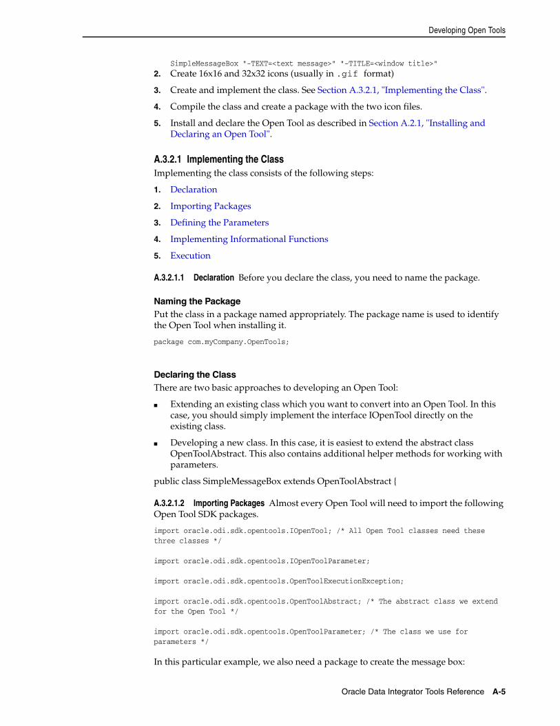
Developing Open Tools
Oracle Data Integrator Tools Reference A-5
SimpleMessageBox "-TEXT=<text message>" "-TITLE=<window title>"2. Create 16x16 and 32x32 icons (usually in .gif format)
3. Create and implement the class. See Section A.3.2.1, "Implementing the Class".
4. Compile the class and create a package with the two icon files.
5. Install and declare the Open Tool as described in Section A.2.1, "Installing and Declaring an Open Tool".
A.3.2.1 Implementing the ClassImplementing the class consists of the following steps:
1. Declaration
2. Importing Packages
3. Defining the Parameters
4. Implementing Informational Functions
5. Execution
A.3.2.1.1 Declaration Before you declare the class, you need to name the package.
Naming the PackagePut the class in a package named appropriately. The package name is used to identify the Open Tool when installing it.
package com.myCompany.OpenTools;
Declaring the ClassThere are two basic approaches to developing an Open Tool:
■ Extending an existing class which you want to convert into an Open Tool. In this case, you should simply implement the interface IOpenTool directly on the existing class.
■ Developing a new class. In this case, it is easiest to extend the abstract class OpenToolAbstract. This also contains additional helper methods for working with parameters.
public class SimpleMessageBox extends OpenToolAbstract {
A.3.2.1.2 Importing Packages Almost every Open Tool will need to import the following Open Tool SDK packages.
import oracle.odi.sdk.opentools.IOpenTool; /* All Open Tool classes need these three classes */
import oracle.odi.sdk.opentools.IOpenToolParameter;
import oracle.odi.sdk.opentools.OpenToolExecutionException;
import oracle.odi.sdk.opentools.OpenToolAbstract; /* The abstract class we extend for the Open Tool */
import oracle.odi.sdk.opentools.OpenToolParameter; /* The class we use for parameters */
In this particular example, we also need a package to create the message box:
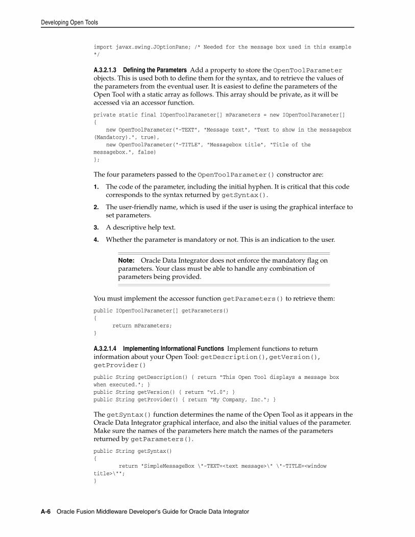
Developing Open Tools
A-6 Oracle Fusion Middleware Developer's Guide for Oracle Data Integrator
import javax.swing.JOptionPane; /* Needed for the message box used in this example */
A.3.2.1.3 Defining the Parameters Add a property to store the OpenToolParameter objects. This is used both to define them for the syntax, and to retrieve the values of the parameters from the eventual user. It is easiest to define the parameters of the Open Tool with a static array as follows. This array should be private, as it will be accessed via an accessor function.
private static final IOpenToolParameter[] mParameters = new IOpenToolParameter[]{ new OpenToolParameter("-TEXT", "Message text", "Text to show in the messagebox (Mandatory).", true), new OpenToolParameter("-TITLE", "Messagebox title", "Title of the messagebox.", false)};
The four parameters passed to the OpenToolParameter() constructor are:
1. The code of the parameter, including the initial hyphen. It is critical that this code corresponds to the syntax returned by getSyntax().
2. The user-friendly name, which is used if the user is using the graphical interface to set parameters.
3. A descriptive help text.
4. Whether the parameter is mandatory or not. This is an indication to the user.
You must implement the accessor function getParameters() to retrieve them:
public IOpenToolParameter[] getParameters(){ return mParameters;}
A.3.2.1.4 Implementing Informational Functions Implement functions to return information about your Open Tool: getDescription(), getVersion(), getProvider()
public String getDescription() { return "This Open Tool displays a message box when executed."; }public String getVersion() { return "v1.0"; }public String getProvider() { return "My Company, Inc."; }
The getSyntax() function determines the name of the Open Tool as it appears in the Oracle Data Integrator graphical interface, and also the initial values of the parameter. Make sure the names of the parameters here match the names of the parameters returned by getParameters().
public String getSyntax(){ return "SimpleMessageBox \"-TEXT=<text message>\" \"-TITLE=<window title>\"";}
Note: Oracle Data Integrator does not enforce the mandatory flag on parameters. Your class must be able to handle any combination of parameters being provided.
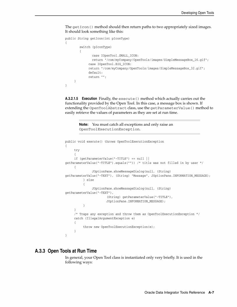
Developing Open Tools
Oracle Data Integrator Tools Reference A-7
The getIcon() method should then return paths to two appropriately sized images. It should look something like this:
public String getIcon(int pIconType){ switch (pIconType) { case IOpenTool.SMALL_ICON: return "/com/myCompany/OpenTools/images/SimpleMessageBox_16.gif"; case IOpenTool.BIG_ICON: return "/com/myCompany/OpenTools/images/SimpleMessageBox_32.gif"; default: return ""; }}
A.3.2.1.5 Execution Finally, the execute() method which actually carries out the functionality provided by the Open Tool. In this case, a message box is shown. If extending the OpenToolAbstract class, use the getParameterValue() method to easily retrieve the values of parameters as they are set at run time.
public void execute() throws OpenToolExecutionException{ try { if (getParameterValue("-TITLE") == null || getParameterValue("-TITLE").equals("")) /* title was not filled in by user */ { JOptionPane.showMessageDialog(null, (String) getParameterValue("-TEXT"), (String) "Message", JOptionPane.INFORMATION_MESSAGE); } else { JOptionPane.showMessageDialog(null, (String) getParameterValue("-TEXT"), (String) getParameterValue("-TITLE"), JOptionPane.INFORMATION_MESSAGE); } } /* Traps any exception and throw them as OpenToolExecutionException */ catch (IllegalArgumentException e) { throw new OpenToolExecutionException(e); }}
A.3.3 Open Tools at Run TimeIn general, your Open Tool class is instantiated only very briefly. It is used in the following ways:
Note: You must catch all exceptions and only raise an OpenToolExecutionException.
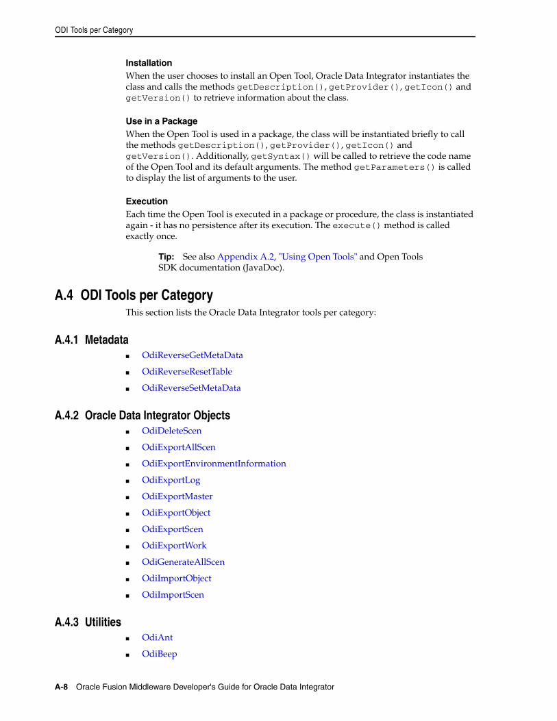
ODI Tools per Category
A-8 Oracle Fusion Middleware Developer's Guide for Oracle Data Integrator
InstallationWhen the user chooses to install an Open Tool, Oracle Data Integrator instantiates the class and calls the methods getDescription(), getProvider(), getIcon() and getVersion() to retrieve information about the class.
Use in a PackageWhen the Open Tool is used in a package, the class will be instantiated briefly to call the methods getDescription(), getProvider(), getIcon() and getVersion(). Additionally, getSyntax() will be called to retrieve the code name of the Open Tool and its default arguments. The method getParameters() is called to display the list of arguments to the user.
ExecutionEach time the Open Tool is executed in a package or procedure, the class is instantiated again - it has no persistence after its execution. The execute() method is called exactly once.
A.4 ODI Tools per CategoryThis section lists the Oracle Data Integrator tools per category:
A.4.1 Metadata■ OdiReverseGetMetaData
■ OdiReverseResetTable
■ OdiReverseSetMetaData
A.4.2 Oracle Data Integrator Objects■ OdiDeleteScen
■ OdiExportAllScen
■ OdiExportEnvironmentInformation
■ OdiExportLog
■ OdiExportMaster
■ OdiExportObject
■ OdiExportScen
■ OdiExportWork
■ OdiGenerateAllScen
■ OdiImportObject
■ OdiImportScen
A.4.3 Utilities■ OdiAnt
■ OdiBeep
Tip: See also Appendix A.2, "Using Open Tools" and Open Tools SDK documentation (JavaDoc).
ODI Tools per Category
Oracle Data Integrator Tools Reference A-9
■ OdiDataQuality
■ OdiKillAgent
■ OdiOSCommand
■ OdiPingAgent
■ OdiPurgeLog
■ OdiReinitializeSeq
■ OdiStartLoadPlan
■ OdiStartLoadPlan
■ OdiUpdateAgentSchedule
A.4.4 Internet Related Tasks■ OdiFtpGet
■ OdiFtpPut
■ OdiInvokeWebService
■ OdiReadMail
■ OdiScpGet
■ OdiScpPut
■ OdiSftpGet
■ OdiSftpPut
■ OdiSendMail
A.4.5 Files■ OdiFileAppend
■ OdiFileCopy
■ OdiFileDelete
■ OdiFileMove
■ OdiFileWait
■ OdiMkDir
■ OdiOutFile
■ OdiSqlUnload
■ OdiUnZip
■ OdiZip
A.4.6 SAP■ OdiSAPALEClient and OdiSAPALEClient3
■ OdiSAPALEServer and OdiSAPALEServer3
A.4.7 XML■ OdiXMLConcat
Alphabetic List of ODI Tools
A-10 Oracle Fusion Middleware Developer's Guide for Oracle Data Integrator
■ OdiXMLSplit
A.4.8 Event Detection■ OdiFileWait
■ OdiReadMail
■ OdiSleep
■ OdiWaitForChildSession
■ OdiWaitForData
■ OdiWaitForLogData
■ OdiWaitForTable
A.4.9 Changed Data Capture■ OdiRefreshJournalCount
■ OdiRetrieveJournalData
■ OdiWaitForData
■ OdiWaitForLogData
■ OdiWaitForTable
A.5 Alphabetic List of ODI ToolsThis section provides an alphabetical list of the Oracle Data Integrator tools.
■ OdiAnt
■ OdiBeep
■ OdiDataQuality
■ OdiDeleteScen
■ OdiExportAllScen
■ OdiExportEnvironmentInformation
■ OdiExportLog
■ OdiExportMaster
■ OdiExportObject
■ OdiExportScen
■ OdiExportWork
■ OdiFileAppend
■ OdiFileCopy
■ OdiFileDelete
■ OdiFileMove
■ OdiFileWait
■ OdiFtpGet
■ OdiFtpPut
Alphabetic List of ODI Tools
Oracle Data Integrator Tools Reference A-11
■ OdiGenerateAllScen
■ OdiImportObject
■ OdiImportScen
■ OdiInvokeWebService
■ OdiKillAgent
■ OdiMkDir
■ OdiOSCommand
■ OdiOutFile
■ OdiPingAgent
■ OdiPurgeLog
■ OdiReadMail
■ OdiRefreshJournalCount
■ OdiReinitializeSeq
■ OdiReverseGetMetaData
■ OdiReverseResetTable
■ OdiReverseSetMetaData
■ OdiRetrieveJournalData
■ OdiSAPALEClient and OdiSAPALEClient3
■ OdiSAPALEServer and OdiSAPALEServer3
■ OdiScpGet
■ OdiScpPut
■ OdiSendMail
■ OdiSftpGet
■ OdiSftpPut
■ OdiSleep
■ OdiSqlUnload
■ OdiStartLoadPlan
■ OdiStartScen
■ OdiUnZip
■ OdiUpdateAgentSchedule
■ OdiWaitForChildSession
■ OdiWaitForData
■ OdiWaitForLogData
■ OdiWaitForTable
■ OdiXMLConcat
■ OdiXMLSplit
■ OdiZip
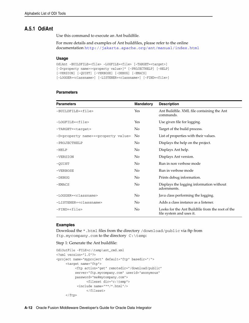
Alphabetic List of ODI Tools
A-12 Oracle Fusion Middleware Developer's Guide for Oracle Data Integrator
A.5.1 OdiAntUse this command to execute an Ant buildfile.
For more details and examples of Ant buildfiles, please refer to the online documentation http://jakarta.apache.org/ant/manual/index.html
UsageOdiAnt -BUILDFILE=<file> -LOGFILE=<file> [-TARGET=<target>][-D<property name>=<property value>]* [-PROJECTHELP] [-HELP][-VERSION] [-QUIET] [-VERBOSE] [-DEBUG] [-EMACS][-LOGGER=<classname>] [-LISTENER=<classname>] [-FIND=<file>]
Parameters
ExamplesDownload the *.html files from the directory /download/public via ftp from ftp.mycompany.com to the directory C:\temp:
Step 1: Generate the Ant buildfile:
OdiOutFile -FILE=c:\temp\ant_cmd.xml<?xml version="1.0"?><project name="myproject" default="ftp" basedir="/"> <target name="ftp"> <ftp action="get" remotedir="/download/public" server="ftp.mycompany.com" userid="anonymous" password="[email protected]"> <fileset dir="c:\temp"> <include name="**/*.html"/> </fileset> </ftp>
Parameters Mandatory Description
-BUILDFILE=<file> Yes Ant Buildfile. XML file containing the Ant commands.
-LOGFILE=<file> Yes Use given file for logging.
-TARGET=<target> No Target of the build process.
-D<property name>=<property value> No List of properties with their values.
-PROJECTHELP No Displays the help on the project.
-HELP No Displays Ant help.
-VERSION No Displays Ant version.
-QUIET No Run in non verbose mode
-VERBOSE No Run in verbose mode
-DEBUG No Prints debug information.
-EMACS No Displays the logging information without adornments.
-LOGGER=<classname> No Java class performing the logging.
-LISTENER=<classname> No Adds a class instance as a listener.
-FIND=<file> No Looks for the Ant Buildfile from the root of the file system and uses it.
Alphabetic List of ODI Tools
Oracle Data Integrator Tools Reference A-13
</target></project>
Step 2: Run the Ant buildfile:
OdiAnt -BUILDFILE=c:\temp\ant_cmd.xml -LOGFILE=c:\temp\ant_cmd.log
A.5.2 OdiBeepUse this command to play a default beep or sound file on the machine hosting the agent.
The following file formats are supported by default:
■ WAV
■ AIF
■ AU
UsageOdiBeep [-FILE=<sound_file>]
Parameters
ExamplesPlays the sound file c:\wav\alert.wav
OdiBeep -FILE=c:\wav\alert.wav
A.5.3 OdiDataQualityUse this command to execute a Batch File to launch a Data Quality project.
UsageOdiDataQuality -BATCH_FILE=<batch_file> [-OUT_FILE=<stdout_file>][-ERR_FILE=<stderr_file>] [-SYNCHRONOUS=<yes|no>]
Note: To play other file formats, you must add the appropriate JavaSound Service Provider Interface (JavaSound SPI) to the application classpath.
Parameters Mandatory Description
-FILE No Path and filename of sound file to play. If not specified, the default beep sound for the machine is used.
Alphabetic List of ODI Tools
A-14 Oracle Fusion Middleware Developer's Guide for Oracle Data Integrator
Parameters
ExamplesThe following command executes a data quality project exported to the C:\oracle\oracledq\metabase_data\metabase\oracledq directory.
OdiDataQuality "-BATCH_FILE=C:\oracle\oracledq\metabase_data\metabase\oracledq\project2\scripts\runproject2.cmd ""-OUT_FILE=C:\temp\output file" "-SYNCHRONOUS=YES"
A.5.4 OdiDeleteScenUse this command to delete a given scenario version.
UsageOdiDeleteScen -SCEN_NAME=<name> -SCEN_VERSION=<version>
Parameters
ExamplesDelete the DWH scenario in version 001
OdiDeleteScen -SCEN_NAME=DWH -SCEN_VERSION=001
A.5.5 OdiExportAllScenUse this command to export a group of scenarios from the connected repository.
Parameters Mandatory Description
-BATCH_FILE=<batch_file> Yes Location of the Data Quality batch file to execute. File name must be an absolute path. The batch file depends on the operating system and is called runprojectN.
Example:
C:\oracle\oracledq\metabase_data\metabase\oracledq\project2\scripts\runproject2.cmd
-OUT_FILE=<stdout_file> No File to redirect standard output to (leave blank for no redirection, use absolute path).
-ERR_FILE=<stderr_file> No File to redirect standard error to (leave blank for no redirection, use absolute path).
-SYNCHRONOUS=<yes|no> No If set to YES, the tool waits for the quality process to complete before returning, with possible error code. If set to NO, the tool ends immediately with success and does not wait for the quality process to complete.
Parameters Mandatory Description
-SCEN_NAME=<name> Yes Name of the scenario to delete.
-SCEN_VERSION=<version> Yes Name of the scenario to delete.
Alphabetic List of ODI Tools
Oracle Data Integrator Tools Reference A-15
The export files are named SCEN_<scenario name><scenario version>.xml. This command reproduces the behavior of the export feature available in Designer and Operator.
UsageOdiExportAllScen -TODIR=<directory> [-FORCE_OVERWRITE=<yes|no>] [-FROM_PROJECT=<project_id>] [-FROM_FOLDER=<folder_id>][-FROM_PACKAGE=<package_id>] [-RECURSIVE_EXPORT=<yes|no>][-XML_VERSION=<1.0>] [-XML_CHARSET=<charset>][-JAVA_CHARSET=<charset>] [-EXPORT_PACK=<YES|NO>][-EXPORT_POP=<YES|NO>] [-EXPORT_TRT=<YES|NO>]VAR=<YES|NO>]
Parameters
Parameters Mandatory Description
-TODIR=<directory> Yes Directory into which the export files are created.
-FORCE_OVERWRITE=<yes|no> No If set to yes, existing export files are overwritten with no warning. Default is No.
-FROM_PROJECT=<project_id> No ID of the project containing the scenarios to export. It is the Internal Identifier that appears in the Version tab of the project window. If this parameter is not set, scenarios from all projects are taken into account for the export.
-FROM_FOLDER=<folder_id> No ID of the folder containing the scenarios to export. It is the Internal Identifier that appears in the Version tab of the folder window. If this parameter is not set, scenarios from all folders are taken into account for the export.
-FROM_PACKAGE=<package_id> No ID of the source package of the scenarios to export. It is the Internal Identifier that appears in the Version tab of the package window. If this parameter is not set, scenarios from all components are taken into account for the export.
-RECURSIVE_EXPORT=<yes|no> No If set to yes, all child objects (schedules) are exported with the scenarios. Default is yes.
-XML_VERSION=<1.0> No Sets the XML version that appears in the XML header. Default is 1.0.
-XML_CHARSET=<charset> No Encoding specified in the XML export file in the tag <?xml version="1.0" encoding="ISO-8859-1"?>. Default value is ISO-8859-1. Supported encodings are available at the following URL:
http://java.sun.com/j2se/1.4.2/docs/guide/intl/encoding.doc.html
-JAVA_CHARSET=<charset> No Target file encoding. Default value is ISO-8859-1. Supported encodings are available at the following URL:
http://java.sun.com/j2se/1.4.2/docs/guide/intl/encoding.doc.html
Alphabetic List of ODI Tools
A-16 Oracle Fusion Middleware Developer's Guide for Oracle Data Integrator
ExamplesExport all scenarios from the DW01 project of Internal Identifier 10022 into the /temp/ directory, with all dependant objects.
OdiExportAllScen -FROM_PROJECT=10022 -TODIR=/temp/ -RECURSIVE_EXPORT=yes
A.5.6 OdiExportEnvironmentInformationUse this command to export the details of the technical environment into a comma separated (.csv) file into the directory of your choice. This information is required for maintenance or support purposes.
UsageOdiExportEnvironmentInformation -TODIR=<toDir> -FILE_NAME=<FileName>[-CHARSET=<charset>] [-SNP_INFO_REC_CODE=<row_code>][-MASTER_REC_CODE=<row_code>] [-WORK_REC_CODE=<row_code>][-AGENT_REC_CODE=<row_code>] [-TECHNO_REC_CODE=<row_code>][-RECORD_SEPARATOR_HEXA=<rec_sep>][-FIELD_SEPARATOR_HEXA=<field_sep] [-TEXT_SEPARATOR=<text_sep>]
Parameters
-EXPORT_PACK=<YES|NO> No Indicates if the scenarios attached to packages should be exported. The Default value is YES.
-EXPORT_POP=<YES|NO> No Indicates if the scenarios attached to interfaces should be exported. The Default value is NO.
-EXPORT_TRT=<YES|NO> No Indicates if the scenarios attached to procedures should be exported. The Default value is NO.
-EXPORT_VAR=<YES|NO> No Indicates if the scenarios attached to variables should be exported. The Default value is NO.
Parameters Mandatory Description
-TODIR=<toDir> Yes Target directory for the export.
-FILE_NAME=<FileName> Yes Name of the CSV export file. Default is snps_tech_inf.csv.
-CHARSET=<charset> No Character set of the export file.
-SNP_INFO_REC_CODE=<row_code> No Code used to identify rows that describe the current version of Oracle Data Integrator and the current user. This code is used in the first field of the record. Default is SUNOPSIS.
-MASTER_REC_CODE=<row_code> No Code for rows containing information about the master repository. Default is MASTER.
-WORK_REC_CODE=<row_code> No Code for rows containing information about the work repository. Default is WORK.
-AGENT_REC_CODE=<row_code> No Code for rows containing information about the various agents that are running. Default is AGENT.
Parameters Mandatory Description
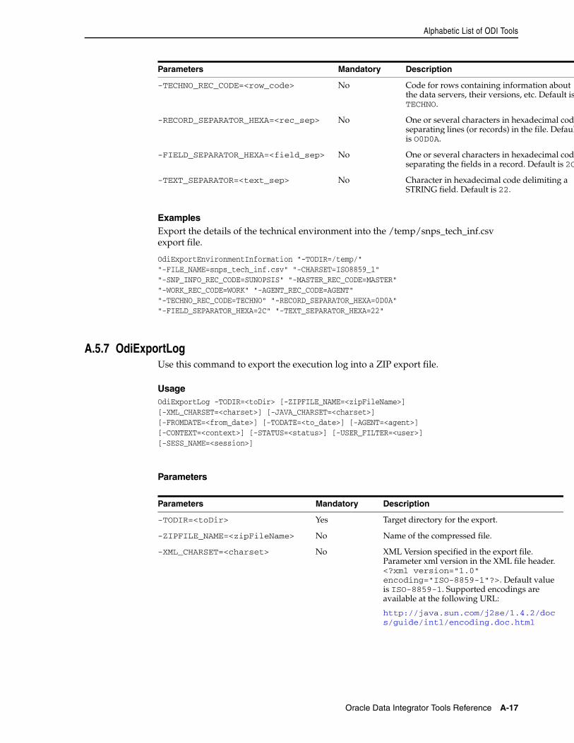
Alphabetic List of ODI Tools
Oracle Data Integrator Tools Reference A-17
ExamplesExport the details of the technical environment into the /temp/snps_tech_inf.csv export file.
OdiExportEnvironmentInformation "-TODIR=/temp/""-FILE_NAME=snps_tech_inf.csv" "-CHARSET=ISO8859_1" "-SNP_INFO_REC_CODE=SUNOPSIS" "-MASTER_REC_CODE=MASTER""-WORK_REC_CODE=WORK" "-AGENT_REC_CODE=AGENT""-TECHNO_REC_CODE=TECHNO" "-RECORD_SEPARATOR_HEXA=0D0A""-FIELD_SEPARATOR_HEXA=2C" "-TEXT_SEPARATOR_HEXA=22"
A.5.7 OdiExportLogUse this command to export the execution log into a ZIP export file.
UsageOdiExportLog -TODIR=<toDir> [-ZIPFILE_NAME=<zipFileName>][-XML_CHARSET=<charset>] [-JAVA_CHARSET=<charset>][-FROMDATE=<from_date>] [-TODATE=<to_date>] [-AGENT=<agent>][-CONTEXT=<context>] [-STATUS=<status>] [-USER_FILTER=<user>][-SESS_NAME=<session>]
Parameters
-TECHNO_REC_CODE=<row_code> No Code for rows containing information about the data servers, their versions, etc. Default isTECHNO.
-RECORD_SEPARATOR_HEXA=<rec_sep> No One or several characters in hexadecimal codeseparating lines (or records) in the file. Defaulis O0D0A.
-FIELD_SEPARATOR_HEXA=<field_sep> No One or several characters in hexadecimal codeseparating the fields in a record. Default is 2C
-TEXT_SEPARATOR=<text_sep> No Character in hexadecimal code delimiting a STRING field. Default is 22.
Parameters Mandatory Description
-TODIR=<toDir> Yes Target directory for the export.
-ZIPFILE_NAME=<zipFileName> No Name of the compressed file.
-XML_CHARSET=<charset> No XML Version specified in the export file. Parameter xml version in the XML file header. <?xml version="1.0" encoding="ISO-8859-1"?>. Default value is ISO-8859-1. Supported encodings are available at the following URL:
http://java.sun.com/j2se/1.4.2/docs/guide/intl/encoding.doc.html
Parameters Mandatory Description
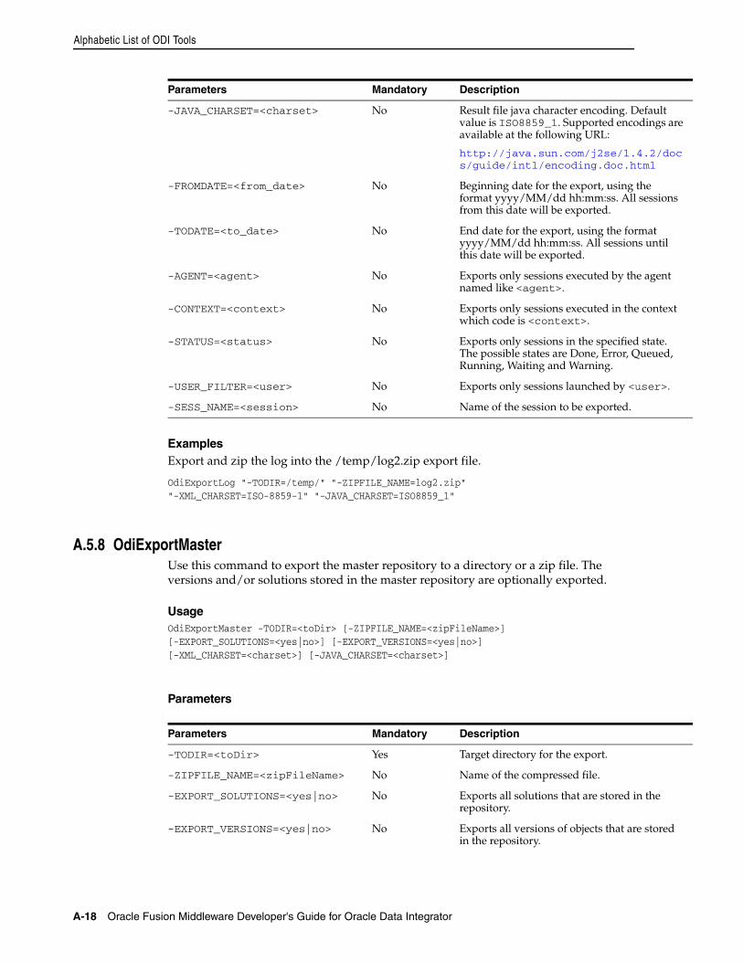
Alphabetic List of ODI Tools
A-18 Oracle Fusion Middleware Developer's Guide for Oracle Data Integrator
ExamplesExport and zip the log into the /temp/log2.zip export file.
OdiExportLog "-TODIR=/temp/" "-ZIPFILE_NAME=log2.zip""-XML_CHARSET=ISO-8859-1" "-JAVA_CHARSET=ISO8859_1"
A.5.8 OdiExportMasterUse this command to export the master repository to a directory or a zip file. The versions and/or solutions stored in the master repository are optionally exported.
UsageOdiExportMaster -TODIR=<toDir> [-ZIPFILE_NAME=<zipFileName>][-EXPORT_SOLUTIONS=<yes|no>] [-EXPORT_VERSIONS=<yes|no>][-XML_CHARSET=<charset>] [-JAVA_CHARSET=<charset>]
Parameters
-JAVA_CHARSET=<charset> No Result file java character encoding. Default value is ISO8859_1. Supported encodings are available at the following URL:
http://java.sun.com/j2se/1.4.2/docs/guide/intl/encoding.doc.html
-FROMDATE=<from_date> No Beginning date for the export, using the format yyyy/MM/dd hh:mm:ss. All sessions from this date will be exported.
-TODATE=<to_date> No End date for the export, using the format yyyy/MM/dd hh:mm:ss. All sessions until this date will be exported.
-AGENT=<agent> No Exports only sessions executed by the agent named like <agent>.
-CONTEXT=<context> No Exports only sessions executed in the context which code is <context>.
-STATUS=<status> No Exports only sessions in the specified state. The possible states are Done, Error, Queued, Running, Waiting and Warning.
-USER_FILTER=<user> No Exports only sessions launched by <user>.
-SESS_NAME=<session> No Name of the session to be exported.
Parameters Mandatory Description
-TODIR=<toDir> Yes Target directory for the export.
-ZIPFILE_NAME=<zipFileName> No Name of the compressed file.
-EXPORT_SOLUTIONS=<yes|no> No Exports all solutions that are stored in the repository.
-EXPORT_VERSIONS=<yes|no> No Exports all versions of objects that are stored in the repository.
Parameters Mandatory Description
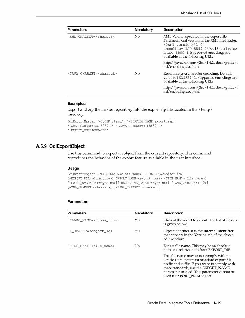
Alphabetic List of ODI Tools
Oracle Data Integrator Tools Reference A-19
ExamplesExport and zip the master repository into the export.zip file located in the /temp/ directory.
OdiExportMaster "-TODIR=/temp/" "-ZIPFILE_NAME=export.zip""-XML_CHARSET=ISO-8859-1" "-JAVA_CHARSET=ISO8859_1""-EXPORT_VERSIONS=YES"
A.5.9 OdiExportObjectUse this command to export an object from the current repository. This command reproduces the behavior of the export feature available in the user interface.
UsageOdiExportObject -CLASS_NAME=<class_name> -I_OBJECT=<object_id>[-EXPORT_DIR=<directory>][EXPORT_NAME=<export_name>|-FILE_NAME=<file_name>] [-FORCE_OVERWRITE=<yes|no>][-RECURSIVE_EXPORT=<yes|no>] [-XML_VERSION=<1.0>][-XML_CHARSET=<charset>] [-JAVA_CHARSET=<charset>]
Parameters
-XML_CHARSET=<charset> No XML Version specified in the export file. Parameter xml version in the XML file header. <?xml version="1.0" encoding="ISO-8859-1"?>. Default value is ISO-8859-1. Supported encodings are available at the following URL:
http://java.sun.com/j2se/1.4.2/docs/guide/intl/encoding.doc.html
-JAVA_CHARSET=<charset> No Result file java character encoding. Default value is ISO8859_1. Supported encodings are available at the following URL:
http://java.sun.com/j2se/1.4.2/docs/guide/intl/encoding.doc.html
Parameters Mandatory Description
-CLASS_NAME=<class_name> Yes Class of the object to export. The list of classes is given below.
-I_OBJECT=<object_id> Yes Object identifier. It is the Internal Identifier that appears in the Version tab of the object edit window.
-FILE_NAME=<file_name> No Export file name. This may be an absolute path or a relative path from EXPORT_DIR.
This file name may or not comply with the Oracle Data Integrator standard export file prefix and suffix. If you want to comply with these standards, use the EXPORT_NAME parameter instead. This parameter cannot be used if EXPORT_NAME is set.
Parameters Mandatory Description
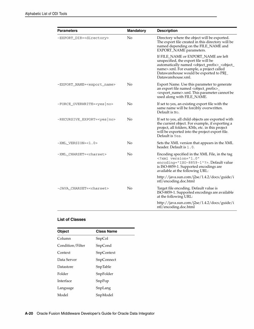
Alphabetic List of ODI Tools
A-20 Oracle Fusion Middleware Developer's Guide for Oracle Data Integrator
List of Classes
-EXPORT_DIR=<directory> No Directory where the object will be exported. The export file created in this directory will be named depending on the FILE_NAME and EXPORT_NAME parameters.
If FILE_NAME or EXPORT_NAME are left unspecified, the export file will be automatically named <object_prefix>_<object_name>.xml. For example, a project called Datawarehouse would be exported to PRJ_Datawarehouse.xml.
-EXPORT_NAME=<export_name> No Export Name. Use this parameter to generate an export file named <object_prefix>_<export_name>.xml. This parameter cannot be used along with FILE_NAME.
-FORCE_OVERWRITE=<yes|no> No If set to yes, an existing export file with the same name will be forcibly overwritten. Default is No.
-RECURSIVE_EXPORT=<yes|no> No If set to yes, all child objects are exported with the current object. For example, if exporting a project, all folders, KMs, etc. in this project will be exported into the project export file. Default is Yes.
-XML_VERSION=<1.0> No Sets the XML version that appears in the XML header. Default is 1.0.
-XML_CHARSET=<charset> No Encoding specified in the XML File, in the tag <?xml version="1.0" encoding="ISO-8859-1"?>. Default value is ISO-8859-1. Supported encodings are available at the following URL:
http://java.sun.com/j2se/1.4.2/docs/guide/intl/encoding.doc.html
-JAVA_CHARSET=<charset> No Target file encoding. Default value is ISO-8859-1. Supported encodings are available at the following URL:
http://java.sun.com/j2se/1.4.2/docs/guide/intl/encoding.doc.html
Object Class Name
Column SnpCol
Condition/Filter SnpCond
Context SnpContext
Data Server SnpConnect
Datastore SnpTable
Folder SnpFolder
Interface SnpPop
Language SnpLang
Model SnpModel
Parameters Mandatory Description
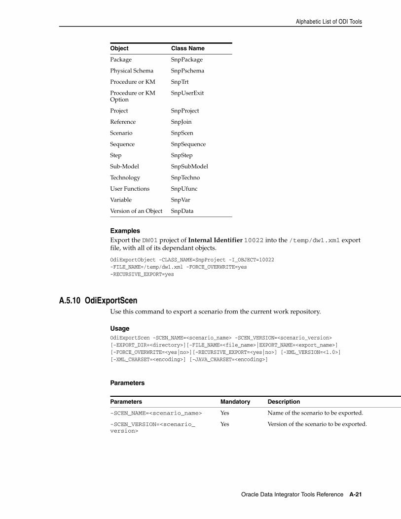
Alphabetic List of ODI Tools
Oracle Data Integrator Tools Reference A-21
ExamplesExport the DW01 project of Internal Identifier 10022 into the /temp/dw1.xml export file, with all of its dependant objects.
OdiExportObject -CLASS_NAME=SnpProject -I_OBJECT=10022-FILE_NAME=/temp/dw1.xml -FORCE_OVERWRITE=yes-RECURSIVE_EXPORT=yes
A.5.10 OdiExportScenUse this command to export a scenario from the current work repository.
UsageOdiExportScen -SCEN_NAME=<scenario_name> -SCEN_VERSION=<scenario_version>[-EXPORT_DIR=<directory>][-FILE_NAME=<file_name>|EXPORT_NAME=<export_name>][-FORCE_OVERWRITE=<yes|no>][-RECURSIVE_EXPORT=<yes|no>] [-XML_VERSION=<1.0>][-XML_CHARSET=<encoding>] [-JAVA_CHARSET=<encoding>]
Parameters
Package SnpPackage
Physical Schema SnpPschema
Procedure or KM SnpTrt
Procedure or KM Option
SnpUserExit
Project SnpProject
Reference SnpJoin
Scenario SnpScen
Sequence SnpSequence
Step SnpStep
Sub-Model SnpSubModel
Technology SnpTechno
User Functions SnpUfunc
Variable SnpVar
Version of an Object SnpData
Parameters Mandatory Description
-SCEN_NAME=<scenario_name> Yes Name of the scenario to be exported.
-SCEN_VERSION=<scenario_version>
Yes Version of the scenario to be exported.
Object Class Name
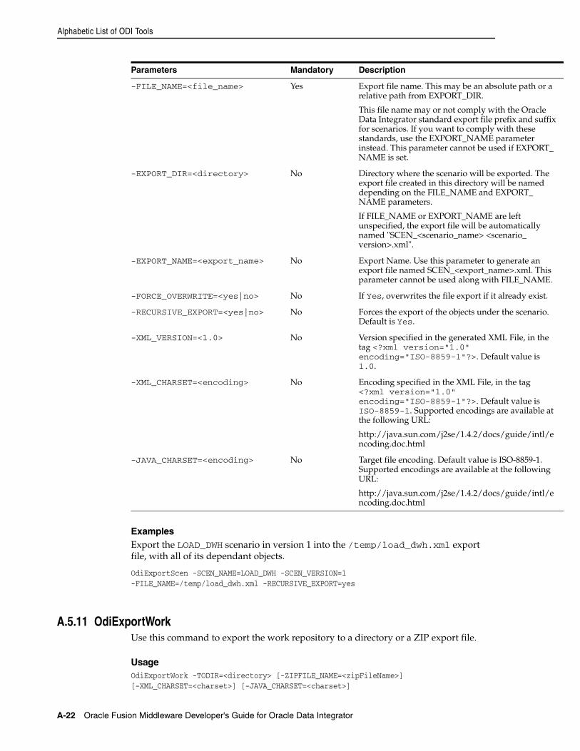
Alphabetic List of ODI Tools
A-22 Oracle Fusion Middleware Developer's Guide for Oracle Data Integrator
ExamplesExport the LOAD_DWH scenario in version 1 into the /temp/load_dwh.xml export file, with all of its dependant objects.
OdiExportScen -SCEN_NAME=LOAD_DWH -SCEN_VERSION=1-FILE_NAME=/temp/load_dwh.xml -RECURSIVE_EXPORT=yes
A.5.11 OdiExportWorkUse this command to export the work repository to a directory or a ZIP export file.
UsageOdiExportWork -TODIR=<directory> [-ZIPFILE_NAME=<zipFileName>][-XML_CHARSET=<charset>] [-JAVA_CHARSET=<charset>]
-FILE_NAME=<file_name> Yes Export file name. This may be an absolute path or a relative path from EXPORT_DIR.
This file name may or not comply with the Oracle Data Integrator standard export file prefix and suffix for scenarios. If you want to comply with these standards, use the EXPORT_NAME parameter instead. This parameter cannot be used if EXPORT_NAME is set.
-EXPORT_DIR=<directory> No Directory where the scenario will be exported. The export file created in this directory will be named depending on the FILE_NAME and EXPORT_NAME parameters.
If FILE_NAME or EXPORT_NAME are left unspecified, the export file will be automatically named "SCEN_<scenario_name> <scenario_version>.xml".
-EXPORT_NAME=<export_name> No Export Name. Use this parameter to generate an export file named SCEN_<export_name>.xml. This parameter cannot be used along with FILE_NAME.
-FORCE_OVERWRITE=<yes|no> No If Yes, overwrites the file export if it already exist.
-RECURSIVE_EXPORT=<yes|no> No Forces the export of the objects under the scenario. Default is Yes.
-XML_VERSION=<1.0> No Version specified in the generated XML File, in the tag <?xml version="1.0" encoding="ISO-8859-1"?>. Default value is 1.0.
-XML_CHARSET=<encoding> No Encoding specified in the XML File, in the tag <?xml version="1.0" encoding="ISO-8859-1"?>. Default value is ISO-8859-1. Supported encodings are available at the following URL:
http://java.sun.com/j2se/1.4.2/docs/guide/intl/encoding.doc.html
-JAVA_CHARSET=<encoding> No Target file encoding. Default value is ISO-8859-1. Supported encodings are available at the following URL:
http://java.sun.com/j2se/1.4.2/docs/guide/intl/encoding.doc.html
Parameters Mandatory Description
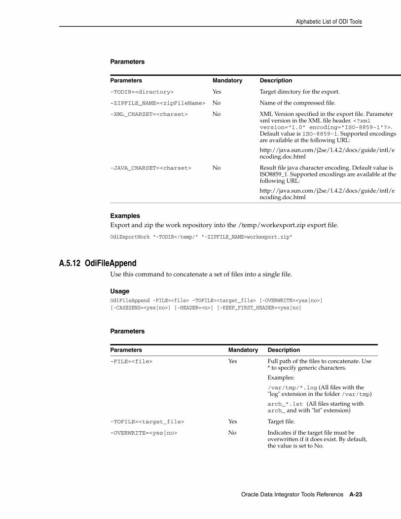
Alphabetic List of ODI Tools
Oracle Data Integrator Tools Reference A-23
Parameters
ExamplesExport and zip the work repository into the /temp/workexport.zip export file.
OdiExportWork "-TODIR=/temp/" "-ZIPFILE_NAME=workexport.zip"
A.5.12 OdiFileAppendUse this command to concatenate a set of files into a single file.
UsageOdiFileAppend -FILE=<file> -TOFILE=<target_file> [-OVERWRITE=<yes|no>][-CASESENS=<yes|no>] [-HEADER=<n>] [-KEEP_FIRST_HEADER=<yes|no]
Parameters
Parameters Mandatory Description
-TODIR=<directory> Yes Target directory for the export.
-ZIPFILE_NAME=<zipFileName> No Name of the compressed file.
-XML_CHARSET=<charset> No XML Version specified in the export file. Parameter xml version in the XML file header. <?xml version="1.0" encoding="ISO-8859-1"?>. Default value is ISO-8859-1. Supported encodings are available at the following URL:
http://java.sun.com/j2se/1.4.2/docs/guide/intl/encoding.doc.html
-JAVA_CHARSET=<charset> No Result file java character encoding. Default value is ISO8859_1. Supported encodings are available at the following URL:
http://java.sun.com/j2se/1.4.2/docs/guide/intl/encoding.doc.html
Parameters Mandatory Description
-FILE=<file> Yes Full path of the files to concatenate. Use * to specify generic characters.
Examples:
/var/tmp/*.log (All files with the "log" extension in the folder /var/tmp)
arch_*.lst (All files starting with arch_ and with "lst" extension)
-TOFILE=<target_file> Yes Target file.
-OVERWRITE=<yes|no> No Indicates if the target file must be overwritten if it does exist. By default, the value is set to No.
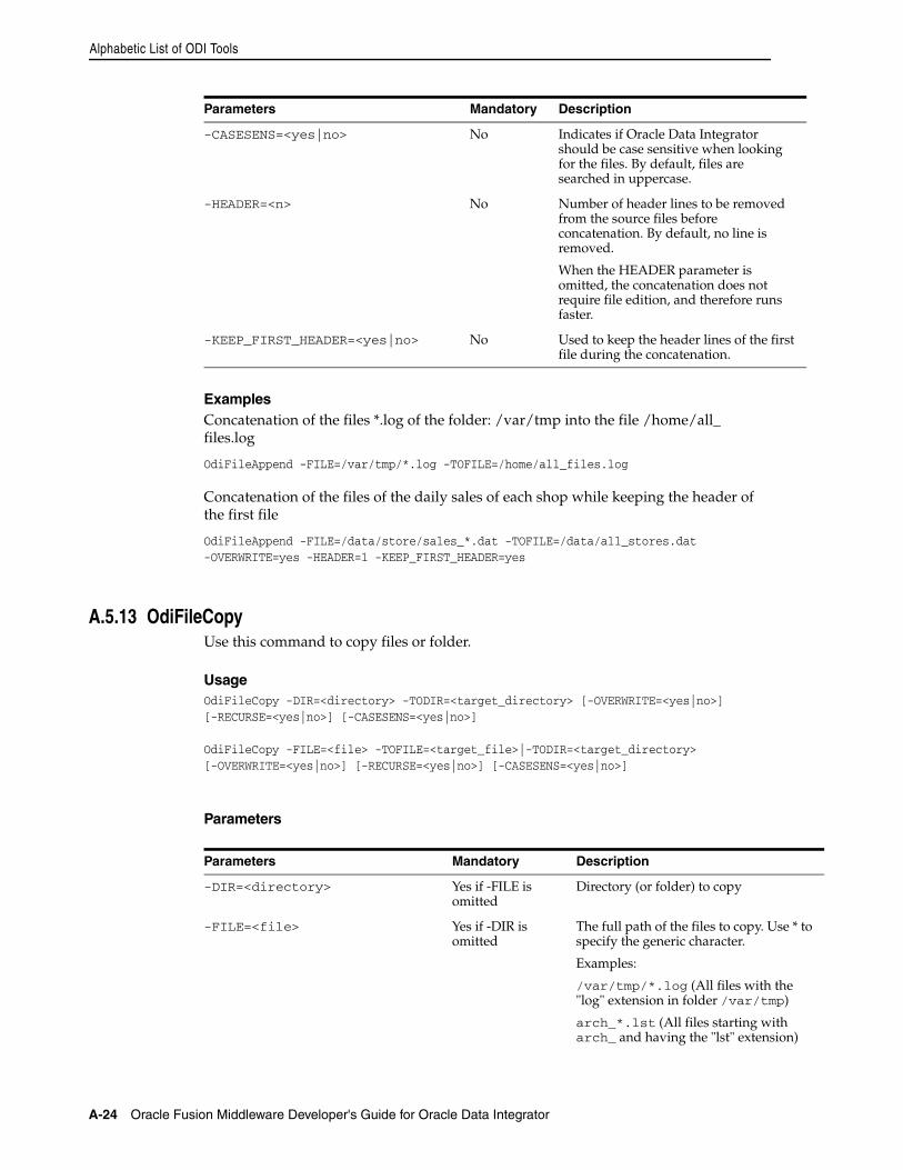
Alphabetic List of ODI Tools
A-24 Oracle Fusion Middleware Developer's Guide for Oracle Data Integrator
ExamplesConcatenation of the files *.log of the folder: /var/tmp into the file /home/all_files.log
OdiFileAppend -FILE=/var/tmp/*.log -TOFILE=/home/all_files.log
Concatenation of the files of the daily sales of each shop while keeping the header of the first file
OdiFileAppend -FILE=/data/store/sales_*.dat -TOFILE=/data/all_stores.dat-OVERWRITE=yes -HEADER=1 -KEEP_FIRST_HEADER=yes
A.5.13 OdiFileCopyUse this command to copy files or folder.
UsageOdiFileCopy -DIR=<directory> -TODIR=<target_directory> [-OVERWRITE=<yes|no>][-RECURSE=<yes|no>] [-CASESENS=<yes|no>]
OdiFileCopy -FILE=<file> -TOFILE=<target_file>|-TODIR=<target_directory>[-OVERWRITE=<yes|no>] [-RECURSE=<yes|no>] [-CASESENS=<yes|no>]
Parameters
-CASESENS=<yes|no> No Indicates if Oracle Data Integrator should be case sensitive when looking for the files. By default, files are searched in uppercase.
-HEADER=<n> No Number of header lines to be removed from the source files before concatenation. By default, no line is removed.
When the HEADER parameter is omitted, the concatenation does not require file edition, and therefore runs faster.
-KEEP_FIRST_HEADER=<yes|no> No Used to keep the header lines of the first file during the concatenation.
Parameters Mandatory Description
-DIR=<directory> Yes if -FILE is omitted
Directory (or folder) to copy
-FILE=<file> Yes if -DIR is omitted
The full path of the files to copy. Use * to specify the generic character.
Examples:
/var/tmp/*.log (All files with the "log" extension in folder /var/tmp)
arch_*.lst (All files starting with arch_ and having the "lst" extension)
Parameters Mandatory Description
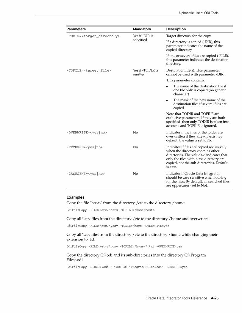
Alphabetic List of ODI Tools
Oracle Data Integrator Tools Reference A-25
ExamplesCopy the file "hosts" from the directory /etc to the directory /home:
OdiFileCopy -FILE=/etc/hosts -TOFILE=/home/hosts
Copy all *.csv files from the directory /etc to the directory /home and overwrite:
OdiFileCopy -FILE=/etc/*.csv -TODIR=/home -OVERWRITE=yes
Copy all *.csv files from the directory /etc to the directory /home while changing their extension to .txt:
OdiFileCopy -FILE=/etc/*.csv -TOFILE=/home/*.txt -OVERWRITE=yes
Copy the directory C:\odi and its sub-directories into the directory C:\Program Files\odi
OdiFileCopy -DIR=C:\odi "-TODIR=C:\Program Files\odi" -RECURSE=yes
-TODIR=<target_directory> Yes if -DIR is specified
Target directory for the copy.
If a directory is copied (-DIR), this parameter indicates the name of the copied directory.
If one or several files are copied (-FILE), this parameter indicates the destination directory.
-TOFILE=<target_file> Yes if -TODIR is omitted
Destination file(s). This parameter cannot be used with parameter -DIR.
This parameter contains:
■ The name of the destination file if one file only is copied (no generic character)
■ The mask of the new name of the destination files if several files are copied
Note that TODIR and TOFILE are exclusive parameters. If they are both specified, then only TODIR is taken into account, and TOFILE is ignored.
-OVERWRITE=<yes|no> No Indicates if the files of the folder are overwritten if they already exist. By default, the value is set to No
-RECURSE=<yes|no> No Indicates if files are copied recursively when the directory contains other directories. The value No indicates that only the files within the directory are copied, not the sub-directories. Default is Yes.
-CASESENS=<yes|no> No Indicates if Oracle Data Integrator should be case sensitive when looking for the files. By default, all searched files are uppercases (set to No).
Parameters Mandatory Description
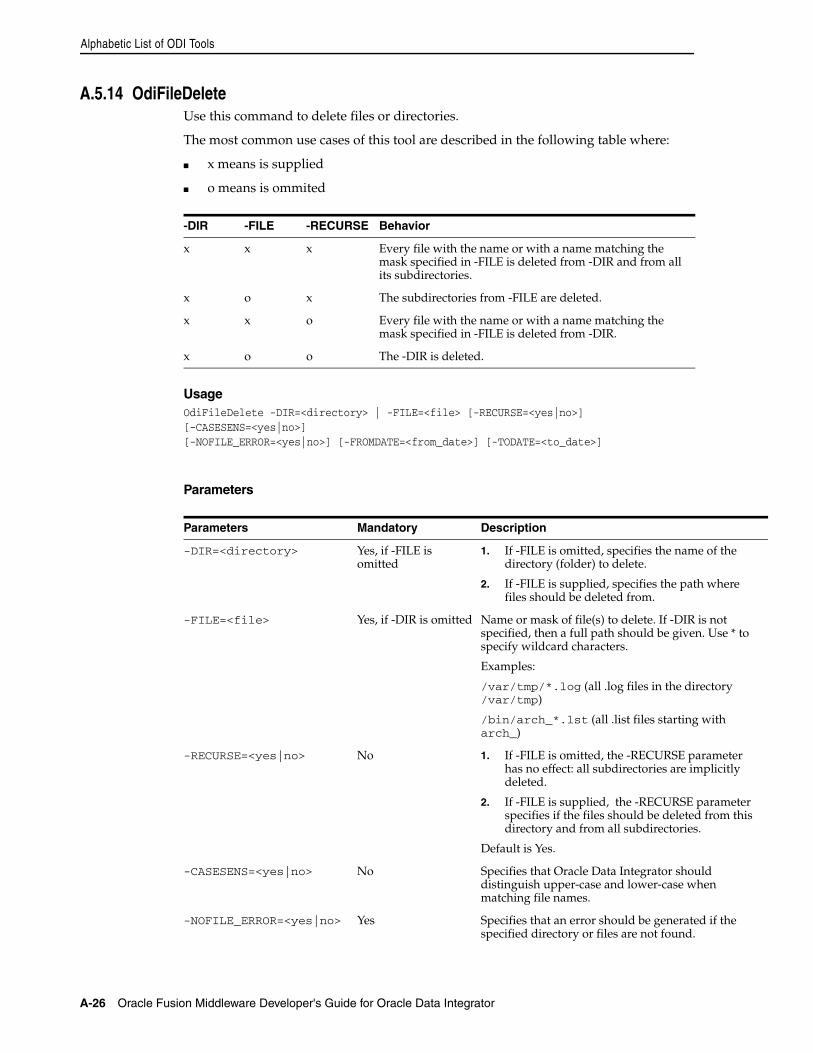
Alphabetic List of ODI Tools
A-26 Oracle Fusion Middleware Developer's Guide for Oracle Data Integrator
A.5.14 OdiFileDeleteUse this command to delete files or directories.
The most common use cases of this tool are described in the following table where:
■ x means is supplied
■ o means is ommited
UsageOdiFileDelete -DIR=<directory> | -FILE=<file> [-RECURSE=<yes|no>] [-CASESENS=<yes|no>][-NOFILE_ERROR=<yes|no>] [-FROMDATE=<from_date>] [-TODATE=<to_date>]
Parameters
-DIR -FILE -RECURSE Behavior
x x x Every file with the name or with a name matching the mask specified in -FILE is deleted from -DIR and from all its subdirectories.
x o x The subdirectories from -FILE are deleted.
x x o Every file with the name or with a name matching the mask specified in -FILE is deleted from -DIR.
x o o The -DIR is deleted.
Parameters Mandatory Description
-DIR=<directory> Yes, if -FILE is omitted
1. If -FILE is omitted, specifies the name of the directory (folder) to delete.
2. If -FILE is supplied, specifies the path where files should be deleted from.
-FILE=<file> Yes, if -DIR is omitted Name or mask of file(s) to delete. If -DIR is not specified, then a full path should be given. Use * to specify wildcard characters.
Examples:
/var/tmp/*.log (all .log files in the directory /var/tmp)
/bin/arch_*.lst (all .list files starting with arch_)
-RECURSE=<yes|no> No 1. If -FILE is omitted, the -RECURSE parameter has no effect: all subdirectories are implicitly deleted.
2. If -FILE is supplied, the -RECURSE parameter specifies if the files should be deleted from this directory and from all subdirectories.
Default is Yes.
-CASESENS=<yes|no> No Specifies that Oracle Data Integrator should distinguish upper-case and lower-case when matching file names.
-NOFILE_ERROR=<yes|no> Yes Specifies that an error should be generated if the specified directory or files are not found.
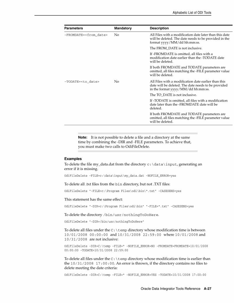
Alphabetic List of ODI Tools
Oracle Data Integrator Tools Reference A-27
ExamplesTo delete the file my_data.dat from the directory c:\data\input, generating an error if it is missing.
OdiFileDelete -FILE=c:\data\input\my_data.dat -NOFILE_ERROR=yes
To delete all .txt files from the bin directory, but not .TXT files:
OdiFileDelete "-FILE=c:\Program Files\odi\bin\*.txt" -CASESENS=yes
This statement has the same effect:
OdiFileDelete "-DIR=c:\Program Files\odi\bin" "-FILE=*.txt" -CASESENS=yes
To delete the directory /bin/usr/nothingToDoHere.
OdiFileDelete "-DIR=/bin/usr/nothingToDoHere"
To delete all files under the C:\temp directory whose modification time is between 10/01/2008 00:00:00 and 10/31/2008 22:59:00 where 10/01/2008 and 10/31/2008 are not inclusive:
OdiFileDelete -DIR=C:\temp -FILE=* -NOFILE_ERROR=NO -FROMDATE=FROMDATE=10/01/2008 00:00:00 -TODATE=10/31/2008 22:59:00
To delete all files under the C:\temp directory whose modification time is earlier than the 10/31/2008 17:00:00. An error is thrown, if the directory contains no files to delete meeting the date criteria:
OdiFileDelete -DIR=C:\temp -FILE=* -NOFILE_ERROR=YES -TODATE=10/31/2008 17:00:00
-FROMDATE=<from_date> No All Files with a modification date later than this date will be deleted. The date needs to be provided in the format yyyy/MM/dd hh:mm:ss.
The FROM_DATE is not inclusive.
If -FROMDATE is omitted, all files with a modification date earlier than the -TODATE date will be deleted.
If both FROMDATE and TODATE parameters are omitted, all files matching the -FILE parameter value will be deleted.
-TODATE=<to_date> No All Files with a modification date earlier than this date will be deleted. The date needs to be provided in the format yyyy/MM/dd hh:mm:ss.
The TO_DATE is not inclusive.
If -TODATE is omitted, all files with a modification date later than the -FROMDATE date will be deleted.
If both FROMDATE and TODATE parameters are omitted, all files matching the -FILE parameter value will be deleted.
Note: It is not possible to delete a file and a directory at the same time by combining the -DIR and -FILE parameters. To achieve that, you must make two calls to OdiFileDelete.
Parameters Mandatory Description
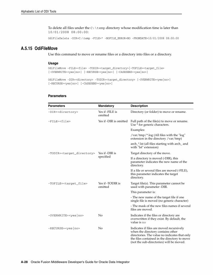
Alphabetic List of ODI Tools
A-28 Oracle Fusion Middleware Developer's Guide for Oracle Data Integrator
To delete all files under the C:\temp directory whose modification time is later than 10/01/2008 08:00:00:
OdiFileDelete -DIR=C:\temp -FILE=* -NOFILE_ERROR=NO -FROMDATE=10/01/2008 08:00:00
A.5.15 OdiFileMoveUse this command to move or rename files or a directory into files or a directory.
UsageOdiFileMove -FILE=<file> -TODIR=<target_directory>|-TOFILE=<target_file>[-OVERWRITE=<yes|no>] [-RECURSE=<yes|no>] [-CASESENS=<yes|no>]
OdiFileMove -DIR=<directory> -TODIR=<target_directory> [-OVERWRITE=<yes|no>][-RECURSE=<yes|no>] [-CASESENS=<yes|no>]
Parameters
Parameters Mandatory Description
-DIR=<directory> Yes if -FILE is omitted
Directory (or folder) to move or rename.
-FILE=<file> Yes if -DIR is omitted Full path of the file(s) to move or rename. Use * for generic characters.
Examples:
/var/tmp/*.log (All files with the "log" extension in the directory /var/tmp)
arch_*.lst (all files starting with arch_ and with "lst" extension)
-TODIR=<target_directory> Yes if -DIR is specified
Target directory of the move.
If a directory is moved (-DIR), this parameter indicates the new name of the directory.
If a file or several files are moved (-FILE), this parameter indicates the target directory.
-TOFILE=<target_file> Yes if -TODIR is omitted
Target file(s). This parameter cannot be used with parameter -DIR.
This parameter is:
- The new name of the target file if one single file is moved (no generic character)
- The mask of the new files names if several files are moved.
-OVERWRITE=<yes|no> No Indicates if the files or directory are overwritten if they exist. By default, the value is no
-RECURSE=<yes|no> No Indicates if files are moved recursively when the directory contains other directories. The value no indicates that only the files contained in the directory to move (not the sub-directories) will be moved.
Alphabetic List of ODI Tools
Oracle Data Integrator Tools Reference A-29
ExamplesRename the "host" file into "hosts.old"
OdiFileMove -FILE=/etc/hosts -TOFILE=/etc/hosts.old
Move the file "hosts" from the directory "/etc" to the directory "/home/odi":
OdiFileMove -FILE=/etc/hosts -TOFILE=/home/odi/hosts
Move all files *.csv from directory "/etc" to directory "/home/odi" with overwrite:
OdiFileMove -FILE=/etc/*.csv -TODIR=/home/odi -OVERWRITE=yes
Move all *.csv files from directory "/etc" to directory "/home/odi" and change their extension to ".txt":
OdiFileMove -FILE=/etc/*.csv -TOFILE=/home/odi/*.txt -OVERWRITE=yes
Rename the directory C:\odi into C:\odi_is_wonderful
OdiFileMove -DIR=C:\odi -TODIR=C:\odi_is_wonderful
Move the directory C:\odi and its sub-folders into the directory C:\Program Files\odi
OdiFileMove -DIR=C:\odi "-TODIR=C:\Program Files\odi" -RECURSE=yes
A.5.16 OdiFileWaitUse this command to manage files events. This command scans regularly a directory and waits for a number of files matching a mask to appear, until a given timeout is reached. When the specified files are found, an action on these files is triggered.
UsageOdiFileWait -DIR=<directory> -PATTERN=<pattern>[-ACTION=<DELETE|COPY|MOVE|APPEND|ZIP|NONE>] [-TODIR=<target_directory>][-TOFILE=<target_file>] [-OVERWRITE=<yes|no>] [-CASESENS=<yes|no>][-FILECOUNT=<n>] [-TIMEOUT=<n>] [-POLLINT=<n>] [-HEADER=<n>][-KEEP_FIRST_HEADER=<yes|no>] [-NOFILE_ERROR=<yes|no>]
-CASESENS=<yes|no> No Indicates if Oracle Data Integrator should be case sensitive when looking for the files. By default, all searched files are uppercases.
Parameters Mandatory Description
Alphabetic List of ODI Tools
A-30 Oracle Fusion Middleware Developer's Guide for Oracle Data Integrator
Parameters
Parameters Mandatory Description
-ACTION=
<DELETE|COPY|MOVE|APPEND|ZIP|NONE>
No Action taken on the files found:
DELETE: Delete the files found
COPY: Copy the files found into the directory TODIR
MOVE: Move or rename the files found into folder TODIR by naming them as specified by TOFILE
APPEND: Concatenates all files found and creates a result file TOFILE. Source files are deleted.
ZIP: Zip the files found and store them into the ZIP file TOFILE
NONE: No action is performed. This is the default behaviour.
-DIR=<directory> Yes Directory (or folder) to scan
-PATTERN=<pattern> Yes Mask of filenames to scan. Use * to specify the generic characters.
Examples:
*.log (All files with the "log" extension)
arch_*.lst (All files starting with arch_ and with the extension "lst")
-TODIR=<target_directory> No Target directory of the action. When the action is:
COPY: Directory where the files are copied
MOVE: Directory where the files are moved
-TOFILE=<target_file> No Destination file(s). When the action is:
MOVE: Renaming mask of the moved files.
APPEND: Name of the file resulting from the concatenation.
ZIP: Name of the resulting ZIP file.
COPY: Renaming mask of the copied files. Renaming rules:
■ any alphanumeric character is replaced in the original filename with the alphanumeric characters specified for <target_file>.
■ '?' at -TOFILE leaves origin symbol on this position
■ '*' at -TOFILE means all remaining symbols from origin filename
Alphabetic List of ODI Tools
Oracle Data Integrator Tools Reference A-31
-OVERWRITE=<yes|no> No Indicates if the destination file(s) will be overwritten if they exist. By default, the value is set to no
Note that if this option is used with APPEND, then the target file will only have the contents of the latest file processed.
-CASESENS=<yes|no> No Indicates if file search is case sensitive. By default, searched files are uppercase.
-FILECOUNT=<n> No Maximum number of files to wait for (default is 0). If this number is reached, the command ends.
The value 0 indicates that we wait for all files until the timeout is reached.
If this parameter is 0 and the timeout is also 0, this parameter is then forced implicitly to 1.
-TIMEOUT=<n> No Maximum waiting time in milliseconds (default is 0)
If this delay is reached, the command yields control to the following command, and this no matter what is the value of parameter FILECOUNT.
The value 0 is used to specify an infinite waiting time (wait until the maximum number of messages to read as specified in parameter FILECOUNT).
-POLLINT=<n> No Interval in milliseconds to search for new files. Default is set to 1000 (1 second), which means that Oracle Data Integrator looks for new messages every second. Files written during the OdiFileWait are taken in account only after being closed (File size unchanged) during this interval.
-HEADER=<n> No This parameter is valid only for the APPEND action.
Number of header lines to suppress from the files before concatenation. Default is no processing (0).
-KEEP_FIRST_HEADER=<yes|no> No This parameter is only valid for the action APPEND.
It is used to keep the header lines of the first file during the concatenation. Default is Yes.
-NOFILE_ERROR=<yes|no> No Indicates the behavior to have if no file is found.
The value No (default) indicates that no error must be generated if no file is found.
Parameters Mandatory Description
Alphabetic List of ODI Tools
A-32 Oracle Fusion Middleware Developer's Guide for Oracle Data Integrator
ExamplesWait indefinitely for file flag.txt in directory c:\events and proceed when this file is detected.
OdiFileWait -ACTION=NONE -DIR=c:\events -PATTERN=flag.txt -FILECOUNT=1-TIMEOUT=0 -POLLINT=1000
Wait indefinitely for file flag.txt in directory c:\events and suppress this file when it is detected.
OdiFileWait -ACTION=DELETE -DIR=c:\events -PATTERN=flag.txt -FILECOUNT=1-TIMEOUT=0 -POLLINT=1000
Wait for the sales files *.dat for 5 minutes and scan every second in directory c:\sales_in, then concatenate into file sales.dat in directory C:\sales_ok. Keep the header of the first file.
OdiFileWait -ACTION=APPEND -DIR=c:\sales_in -PATTERN=*.datTOFILE=c:\sales_ok\sales.dat -FILECOUNT=0 -TIMEOUT=350000 -POLLINT=1000-HEADER=1 -KEEP_FIRST_HEADER=yes -OVERWRITE=yes
Wait for the sales files *.dat for 5 minutes every second in directory c:\sales_in, then copy these files into directory C:\sales_ok. Do not overwrite.
OdiFileWait -ACTION=COPY -DIR=c:\sales_in -PATTERN=*.dat -TODIR=c:\sales_ok-FILECOUNT=0 -TIMEOUT=350000 -POLLINT=1000 -OVERWRITE=no
Wait for the sales files *.dat for 5 minutes every second in directory c:\sales_in and then archive these files into a zip file.
OdiFileWait -ACTION=ZIP -DIR=c:\sales_in -PATTERN=*.dat-TOFILE=c:\sales_ok\sales.zip -FILECOUNT=0 -TIMEOUT=350000-POLLINT=1000 -OVERWRITE=yes
Wait for the sales files *.dat for 5 minutes every second into directory c:\sales_in, then move these files into directory C:\sales_ok. Do not overwrite. Append .bak to the file names.
OdiFileWait -ACTION=MOVE -DIR=c:\sales_in -PATTERN=*.dat-TODIR=c:\sales_ok -TOFILE=*.bak -FILECOUNT=0 -TIMEOUT=350000-POLLINT=1000 -OVERWRITE=no
A.5.17 OdiFtpGetUse this command to download a file from a FTP server.
UsageOdiFtpGet -HOST=<ftp server host name> -USER=<ftp user> [PASSWORD=<ftp user password>] -REMOTE_DIR=<remote dir on ftp host>[-REMOTE_FILE=<file name under the -REMOTE_DIR>] -LOCAL_DIR=<local dir>[-LOCAL_FILE=<file name under the –LOCAL_DIR>] [-PASSIVE_MODE=<yes|no>] [-TIMEOUT=<time in seconds>]
Parameters
Parameters Mandatory Description
-HOST=<host name of the Ftp server> Yes The host name of the FTP server
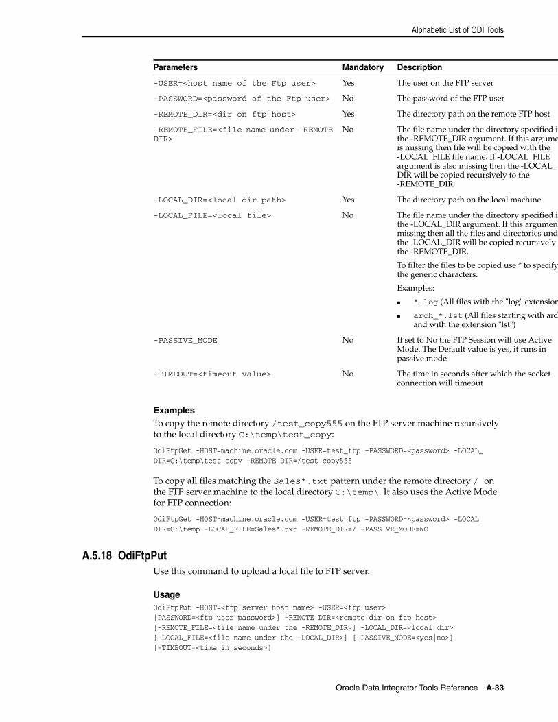
Alphabetic List of ODI Tools
Oracle Data Integrator Tools Reference A-33
ExamplesTo copy the remote directory /test_copy555 on the FTP server machine recursively to the local directory C:\temp\test_copy:
OdiFtpGet -HOST=machine.oracle.com -USER=test_ftp -PASSWORD=<password> -LOCAL_DIR=C:\temp\test_copy -REMOTE_DIR=/test_copy555
To copy all files matching the Sales*.txt pattern under the remote directory / on the FTP server machine to the local directory C:\temp\. It also uses the Active Mode for FTP connection:
OdiFtpGet -HOST=machine.oracle.com -USER=test_ftp -PASSWORD=<password> -LOCAL_DIR=C:\temp -LOCAL_FILE=Sales*.txt -REMOTE_DIR=/ -PASSIVE_MODE=NO
A.5.18 OdiFtpPutUse this command to upload a local file to FTP server.
UsageOdiFtpPut -HOST=<ftp server host name> -USER=<ftp user> [PASSWORD=<ftp user password>] -REMOTE_DIR=<remote dir on ftp host>[-REMOTE_FILE=<file name under the -REMOTE_DIR>] -LOCAL_DIR=<local dir>[-LOCAL_FILE=<file name under the –LOCAL_DIR>] [-PASSIVE_MODE=<yes|no>] [-TIMEOUT=<time in seconds>]
-USER=<host name of the Ftp user> Yes The user on the FTP server
-PASSWORD=<password of the Ftp user> No The password of the FTP user
-REMOTE_DIR=<dir on ftp host> Yes The directory path on the remote FTP host
-REMOTE_FILE=<file name under -REMOTE DIR>
No The file name under the directory specified inthe -REMOTE_DIR argument. If this argumeis missing then file will be copied with the -LOCAL_FILE file name. If -LOCAL_FILE argument is also missing then the -LOCAL_DIR will be copied recursively to the -REMOTE_DIR
-LOCAL_DIR=<local dir path> Yes The directory path on the local machine
-LOCAL_FILE=<local file> No The file name under the directory specified inthe -LOCAL_DIR argument. If this argumentmissing then all the files and directories undethe -LOCAL_DIR will be copied recursively tthe -REMOTE_DIR.
To filter the files to be copied use * to specify the generic characters.
Examples:
■ *.log (All files with the "log" extension
■ arch_*.lst (All files starting with archand with the extension "lst")
-PASSIVE_MODE No If set to No the FTP Session will use Active Mode. The Default value is yes, it runs in passive mode
-TIMEOUT=<timeout value> No The time in seconds after which the socket connection will timeout
Parameters Mandatory Description
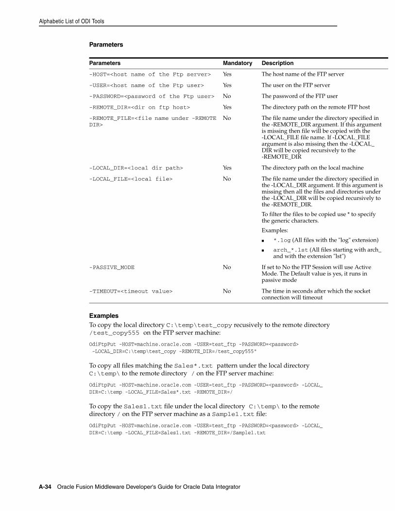
Alphabetic List of ODI Tools
A-34 Oracle Fusion Middleware Developer's Guide for Oracle Data Integrator
Parameters
ExamplesTo copy the local directory C:\temp\test_copy recusively to the remote directory /test_copy555 on the FTP server machine:
OdiFtpPut -HOST=machine.oracle.com -USER=test_ftp -PASSWORD=<password> -LOCAL_DIR=C:\temp\test_copy -REMOTE_DIR=/test_copy555"
To copy all files matching the Sales*.txt pattern under the local directory C:\temp\ to the remote directory / on the FTP server machine:
OdiFtpPut -HOST=machine.oracle.com -USER=test_ftp -PASSWORD=<password> -LOCAL_DIR=C:\temp -LOCAL_FILE=Sales*.txt -REMOTE_DIR=/
To copy the Sales1.txt file under the local directory C:\temp\ to the remote directory / on the FTP server machine as a Sample1.txt file:
OdiFtpPut -HOST=machine.oracle.com -USER=test_ftp -PASSWORD=<password> -LOCAL_DIR=C:\temp -LOCAL_FILE=Sales1.txt -REMOTE_DIR=/Sample1.txt
Parameters Mandatory Description
-HOST=<host name of the Ftp server> Yes The host name of the FTP server
-USER=<host name of the Ftp user> Yes The user on the FTP server
-PASSWORD=<password of the Ftp user> No The password of the FTP user
-REMOTE_DIR=<dir on ftp host> Yes The directory path on the remote FTP host
-REMOTE_FILE=<file name under -REMOTE DIR>
No The file name under the directory specified in the -REMOTE_DIR argument. If this argument is missing then file will be copied with the -LOCAL_FILE file name. If -LOCAL_FILE argument is also missing then the -LOCAL_DIR will be copied recursively to the -REMOTE_DIR
-LOCAL_DIR=<local dir path> Yes The directory path on the local machine
-LOCAL_FILE=<local file> No The file name under the directory specified in the -LOCAL_DIR argument. If this argument is missing then all the files and directories under the -LOCAL_DIR will be copied recursively to the -REMOTE_DIR.
To filter the files to be copied use * to specify the generic characters.
Examples:
■ *.log (All files with the "log" extension)
■ arch_*.lst (All files starting with arch_ and with the extension "lst")
-PASSIVE_MODE No If set to No the FTP Session will use Active Mode. The Default value is yes, it runs in passive mode
-TIMEOUT=<timeout value> No The time in seconds after which the socket connection will timeout
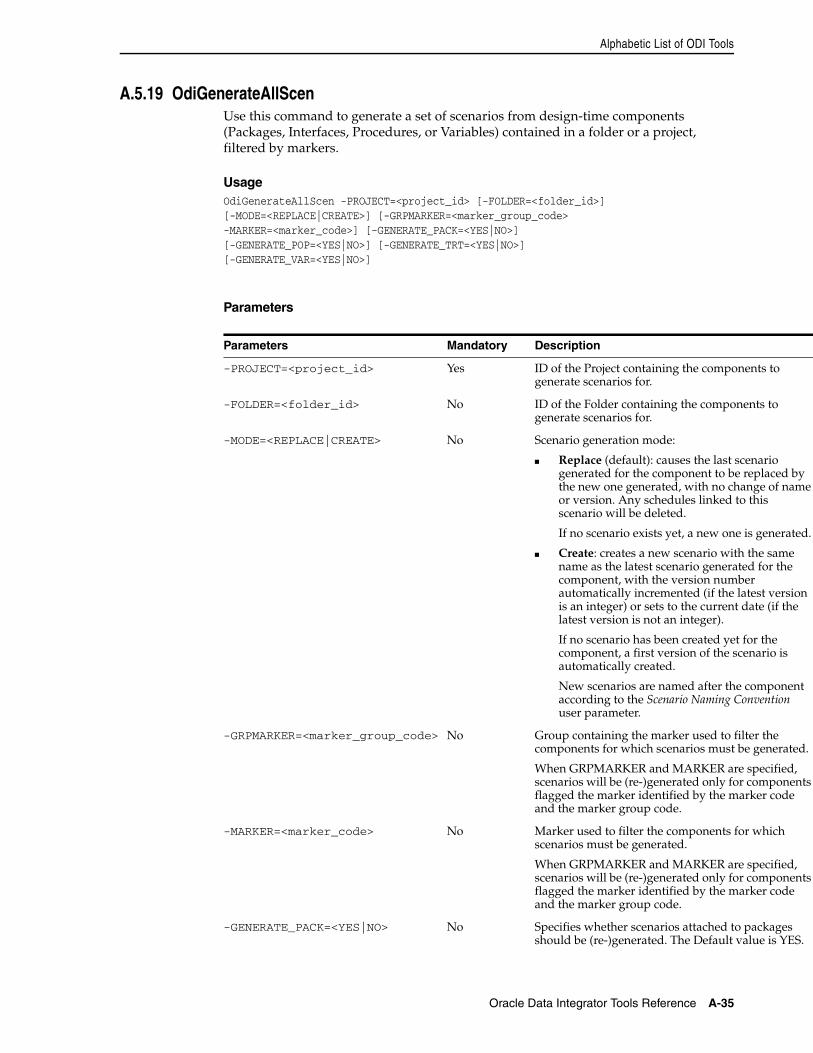
Alphabetic List of ODI Tools
Oracle Data Integrator Tools Reference A-35
A.5.19 OdiGenerateAllScenUse this command to generate a set of scenarios from design-time components (Packages, Interfaces, Procedures, or Variables) contained in a folder or a project, filtered by markers.
UsageOdiGenerateAllScen -PROJECT=<project_id> [-FOLDER=<folder_id>][-MODE=<REPLACE|CREATE>] [-GRPMARKER=<marker_group_code>-MARKER=<marker_code>] [-GENERATE_PACK=<YES|NO>][-GENERATE_POP=<YES|NO>] [-GENERATE_TRT=<YES|NO>][-GENERATE_VAR=<YES|NO>]
Parameters
Parameters Mandatory Description
-PROJECT=<project_id> Yes ID of the Project containing the components to generate scenarios for.
-FOLDER=<folder_id> No ID of the Folder containing the components to generate scenarios for.
-MODE=<REPLACE|CREATE> No Scenario generation mode:
■ Replace (default): causes the last scenario generated for the component to be replaced by the new one generated, with no change of name or version. Any schedules linked to this scenario will be deleted.
If no scenario exists yet, a new one is generated.
■ Create: creates a new scenario with the same name as the latest scenario generated for the component, with the version number automatically incremented (if the latest version is an integer) or sets to the current date (if the latest version is not an integer).
If no scenario has been created yet for the component, a first version of the scenario is automatically created.
New scenarios are named after the component according to the Scenario Naming Convention user parameter.
-GRPMARKER=<marker_group_code> No Group containing the marker used to filter the components for which scenarios must be generated.
When GRPMARKER and MARKER are specified, scenarios will be (re-)generated only for components flagged the marker identified by the marker code and the marker group code.
-MARKER=<marker_code> No Marker used to filter the components for which scenarios must be generated.
When GRPMARKER and MARKER are specified, scenarios will be (re-)generated only for components flagged the marker identified by the marker code and the marker group code.
-GENERATE_PACK=<YES|NO> No Specifies whether scenarios attached to packages should be (re-)generated. The Default value is YES.
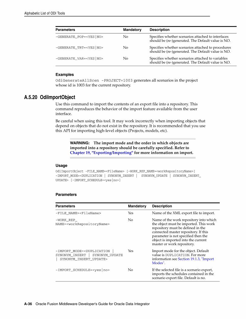
Alphabetic List of ODI Tools
A-36 Oracle Fusion Middleware Developer's Guide for Oracle Data Integrator
ExamplesOdiGenerateAllScen -PROJECT=1003 generates all scenarios in the project whose id is 1003 for the current repository.
A.5.20 OdiImportObjectUse this command to import the contents of an export file into a repository. This command reproduces the behavior of the import feature available from the user interface.
Be careful when using this tool. It may work incorrectly when importing objects that depend on objects that do not exist in the repository. It is recommended that you use this API for importing high-level objects (Projects, models, etc).
UsageOdiImportObject -FILE_NAME=<FileName> [-WORK_REP_NAME=<workRepositoryName>]-IMPORT_MODE=<DUPLICATION | SYNONYM_INSERT | SYNONYM_UPDATE | SYNONYM_INSERT_UPDATE> [-IMPORT_SCHEDULE=<yes|no>]
Parameters
-GENERATE_POP=<YES|NO> No Specifies whether scenarios attached to interfaces should be (re-)generated. The Default value is NO.
-GENERATE_TRT=<YES|NO> No Specifies whether scenarios attached to procedures should be (re-)generated. The Default value is NO.
-GENERATE_VAR=<YES|NO> No Specifies whether scenarios attached to variables should be (re-)generated. The Default value is NO.
WARNING: The import mode and the order in which objects are imported into a repository should be carefully specified. Refer to Chapter 19, "Exporting/Importing" for more information on import.
Parameters Mandatory Description
-FILE_NAME=<FileName> Yes Name of the XML export file to import.
-WORK_REP_NAME=<workRepositoryName>
No Name of the work repository into which the object must be imported. This work repository must be defined in the connected master repository. If this parameter is not specified then the object is imported into the current master or work repository.
-IMPORT_MODE=<DUPLICATION | SYNONYM_INSERT | SYNONYM_UPDATE | SYNONYM_INSERT_UPDATE>
Yes Import mode for the object. Default value is DUPLICATION. For more information see Section 19.1.3, "Import Modes".
-IMPORT_SCHEDULE=<yes|no> No If the selected file is a scenario export, imports the schedules contained in the scenario export file. Default is no.
Parameters Mandatory Description
Alphabetic List of ODI Tools
Oracle Data Integrator Tools Reference A-37
ExamplesImports the /temp/DW01.xml export file (a project) into the WORKREP work repository using DUPLICATION mode .
OdiImportObject -FILE_NAME=/temp/DW01.xml -WORK_REP_NAME=WORKREP-IMPORT_MODE=DUPLICATION
A.5.21 OdiImportScenUse this command to import a scenario into the current work repository from an export file.
UsageOdiImportScen -FILE_NAME=<FileName> [-IMPORT_MODE=<DUPLICATION |SYNONYM_INSERT | SYNONYM_UPDATE | SYNONYM_INSERT_UPDATE>]
Parameters
Examples Imports the /temp/load_dwh.xml export file (a scenario) into the current work repository using DUPLICATION mode .
OdiImportScen -FILE_NAME=/temp/load_dwh.xml -IMPORT_MODE=DUPLICATION
A.5.22 OdiInvokeWebServiceUse this command to invoke a web service over HTTP/HTTPS and write the response to an XML file.
This tool invokes a specific operation on a port of a web service whose description file (WSDL) URL is provided.
If this operation requires a web service request that is provided either in a request file, or directly written out in the tool call (<XML Request>). This request file can have two different formats (XML which correspons to the XML body only or SOAP which corrsponds to the full-formed SOAP envelope including a SOAP header and body) specified in the RESPONSE_FILE_FORMAT parameter. The response of the web service request is written to an XML file that can be processed afterwards in Oracle Data Integrator. If the web service operation is one-way and does not return any response, no response file is generated.
Parameters Mandatory Description
-FILE_NAME=<FileName> Yes Name of the export file.
-IMPORT_MODE=<DUPLICATION | SYNONYM_INSERT | SYNONYM_UPDATE | SYNONYM_INSERT_UPDATE>
No Import mode of the scenario. Default value is DUPLICATION. For more information on the import modes, see Section 19.1.3, "Import Modes".
Note: This tool replaces the OdiExecuteWebService tool.
Alphabetic List of ODI Tools
A-38 Oracle Fusion Middleware Developer's Guide for Oracle Data Integrator
UsageOdiInvokeWebService -URL=<url> -PORT=<port> -OPERATION=<operation>[<XML Request>][-REQUEST_FILE=<xml_request_file>] [-RESPONSE_MODE=<NO_FILE|NEW_FILE|APPEND>][-RESPONSE_FILE=<xml_response_file>] [-RESPONSE_XML_ENCODING=<charset>][-RESPONSE_FILE_CHARSET=<charset>] [-RESPONSE_FILE_FORMAT=<XML|SOAP>][-HTTP_USER=<user>][-HTTP_PASS=<password>] [-TIMEOUT=<timeout>]
Parameters
Parameters Mandatory Description
-URL=<url> Yes URL of the Web Service Description File (WSDL) file describing the web service.
-PORT_TYPE=<port_type> Yes Name of the WSDL port type to invoke.
-OPERATION=<operation> Yes Name of the web service operation to invoke.
<XML Request> No Request message in SOAP (Simple Object Access Protocol) format. This message should be provided on the line immediately following the OdiInvokeWebService call.
The request can alternately be passed via a file which location is provided with the REQUEST_FILE parameter.
-REQUEST_FILE=<xml_request_file> No Location of the XML file containing the request message in SOAP (Simple Object Access Protocol) format.
The request can alternately be directly written out in the tool call (<xmlRequest>).
-RESPONSE_MODE=<NO_FILE|NEW_FILE|APPEND> No Generation mode for the response file. This parameter takes the following values:
■ NO_FILE (default): No response file is generated.
■ NEW_FILE: A new response file is generated. If the file already exists, it is overwritten.
■ APPEND: The response is appended to the file. If the file does not exist, it is created.
-RESPONSE_FILE=<file> Depends The name of the result file to write. Mandatory if -RESPONSE_MODE is NEW_FILE or APPEND.
Alphabetic List of ODI Tools
Oracle Data Integrator Tools Reference A-39
The following table lists some of the most common XML/Java character encoding schemes. A more complete list is available at:
http://java.sun.com/j2se/1.4.2/docs/guide/intl/encoding.doc.html
-RESPONSE_FILE_CHARSET=<charset> Depends Response file character encoding. See the table below. Mandatory if -RESPONSE_MODE is NEW_FILE or APPEND.
-RESPONSE_XML_ENCODING=<charset> Depends Character encoding that will be indicated in the XML declaration header of the response file. See the table below. Mandatory if -RESPONSE_MODE is not NO_FILE.
-RESPONSE_FILE_FORMAT=<XML|SOAP> No Format of the request and response file.
■ If XML is selected (default), the request is processed as a SOAP body. The tool adds default SOAP header and envelope content to this body before sending the request. The response is stripped from its SOAP envelope and headers and only the response's body is written to the response file.
■ If SOAP is selected, the request is processed as a full-formed SOAP envelope and is sent as is. The response is also written to the response file with no processing.
-HTTP_USER=<user> No User account authenticating on the HTTP server.
-HTTP_PASS=<password> No Password of the HTTP user.
-TIMEOUT=<timeout> No The web service request waits for a reply for this time before considering that the server will not provide a response and an error is produced. If no value is given, there is no timeout.
XML Charset Java Charset
US-ASCII ASCII
UTF-8 UTF8
UTF-16 UTF-16
ISO-8859-1 ISO8859_1
Parameters Mandatory Description
Alphabetic List of ODI Tools
A-40 Oracle Fusion Middleware Developer's Guide for Oracle Data Integrator
ExamplesThe following web service call returns the capital city for a given country (the ISO country code is sent in the request). Note that the request and response format, as well as the port and operations available, are defined in the WSDL passed in the URL parameter.
OdiInvokeWebService --URL=http://www.oorsprong.org/websamples.countryinfo/CountryInfoService.wso?WSDL -PORT_TYPE=CountryInfoServiceSoapType -OPERATION=CapitalCity-RESPONSE_MODE=NEW_FILE -RESPONSE_XML_ENCODING=ISO-8859-1"-RESPONSE_FILE=/temp/result.xml" -RESPONSE_FILE_CHARSET=ISO8859_1 -RESPONSE_FILE_FORMAT=XML<CapitalCityRequest><sCountryISOCode>US</sCountryISOCode></CapitalCityRequest>
The generated /temp/result.xml file contains the following:
<CapitalCityResponse><m:CapitalCityResponse><m:CapitalCityResult>Washington</m:CapitalCityResult></m:CapitalCityResponse></CapitalCityResponse>
PackagesOracle Data Integrator provides a special graphical interface for calling OdiInvokeWebService in packages. See Chapter 15, "Working with Web Services in Oracle Data Integrator" for more information.
A.5.23 OdiKillAgentUse this command to kill a standalone agent.
Java EE Agents deployed in an application server cannot be killed using this tool and must be stopped using the application server utilities.
UsageOdiKillAgent (-PORT=<TCP/IP Port>|-NAME=<physical_agent_name>) [-IMMEDIATE=<yes|no>] [-MAX_WAIT=<timeout>]
Parameters
Parameters Mandatory Description
-PORT=<TCP/IP Port> No If this parameter is specified, the agent running on the local machine with the specified port is killed. Note that the -PORT parameter has precedence over the -AGENT_NAME parameter.
-NAME=<physical_agent_name>
Yes If this parameter is specified, the physical agent whose name is provided is killed. This agent may be a local or remote agent. It must be declared in the master repository.
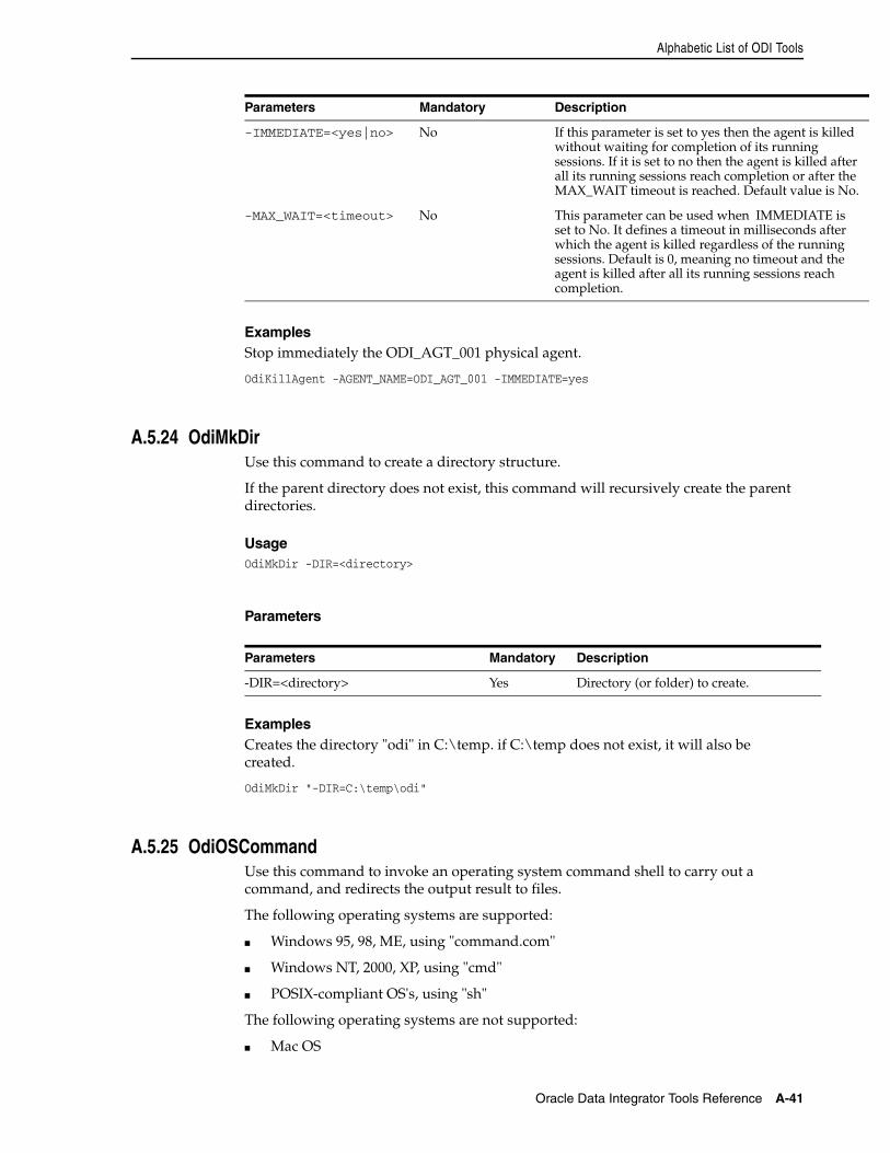
Alphabetic List of ODI Tools
Oracle Data Integrator Tools Reference A-41
ExamplesStop immediately the ODI_AGT_001 physical agent.
OdiKillAgent -AGENT_NAME=ODI_AGT_001 -IMMEDIATE=yes
A.5.24 OdiMkDirUse this command to create a directory structure.
If the parent directory does not exist, this command will recursively create the parent directories.
UsageOdiMkDir -DIR=<directory>
Parameters
ExamplesCreates the directory "odi" in C:\temp. if C:\temp does not exist, it will also be created.
OdiMkDir "-DIR=C:\temp\odi"
A.5.25 OdiOSCommandUse this command to invoke an operating system command shell to carry out a command, and redirects the output result to files.
The following operating systems are supported:
■ Windows 95, 98, ME, using "command.com"
■ Windows NT, 2000, XP, using "cmd"
■ POSIX-compliant OS's, using "sh"
The following operating systems are not supported:
■ Mac OS
-IMMEDIATE=<yes|no> No If this parameter is set to yes then the agent is killed without waiting for completion of its running sessions. If it is set to no then the agent is killed after all its running sessions reach completion or after the MAX_WAIT timeout is reached. Default value is No.
-MAX_WAIT=<timeout> No This parameter can be used when IMMEDIATE is set to No. It defines a timeout in milliseconds after which the agent is killed regardless of the running sessions. Default is 0, meaning no timeout and the agent is killed after all its running sessions reach completion.
Parameters Mandatory Description
-DIR=<directory> Yes Directory (or folder) to create.
Parameters Mandatory Description
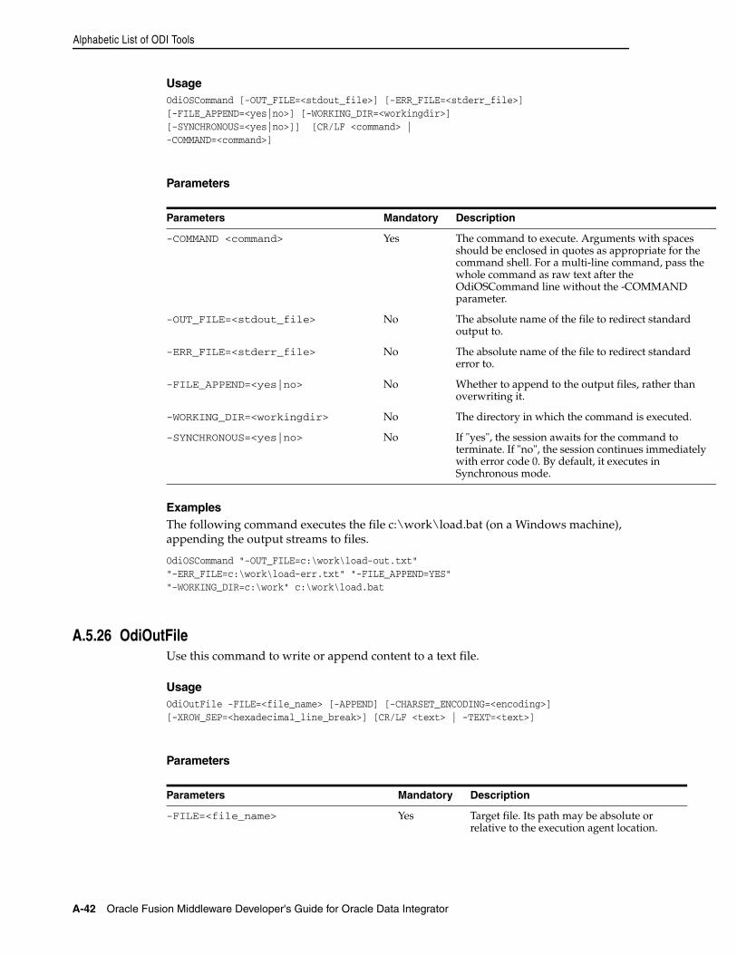
Alphabetic List of ODI Tools
A-42 Oracle Fusion Middleware Developer's Guide for Oracle Data Integrator
UsageOdiOSCommand [-OUT_FILE=<stdout_file>] [-ERR_FILE=<stderr_file>][-FILE_APPEND=<yes|no>] [-WORKING_DIR=<workingdir>][-SYNCHRONOUS=<yes|no>]] [CR/LF <command> |-COMMAND=<command>]
Parameters
ExamplesThe following command executes the file c:\work\load.bat (on a Windows machine), appending the output streams to files.
OdiOSCommand "-OUT_FILE=c:\work\load-out.txt""-ERR_FILE=c:\work\load-err.txt" "-FILE_APPEND=YES""-WORKING_DIR=c:\work" c:\work\load.bat
A.5.26 OdiOutFileUse this command to write or append content to a text file.
UsageOdiOutFile -FILE=<file_name> [-APPEND] [-CHARSET_ENCODING=<encoding>][-XROW_SEP=<hexadecimal_line_break>] [CR/LF <text> | -TEXT=<text>]
Parameters
Parameters Mandatory Description
-COMMAND <command> Yes The command to execute. Arguments with spaces should be enclosed in quotes as appropriate for the command shell. For a multi-line command, pass the whole command as raw text after the OdiOSCommand line without the -COMMAND parameter.
-OUT_FILE=<stdout_file> No The absolute name of the file to redirect standard output to.
-ERR_FILE=<stderr_file> No The absolute name of the file to redirect standard error to.
-FILE_APPEND=<yes|no> No Whether to append to the output files, rather than overwriting it.
-WORKING_DIR=<workingdir> No The directory in which the command is executed.
-SYNCHRONOUS=<yes|no> No If "yes", the session awaits for the command to terminate. If "no", the session continues immediately with error code 0. By default, it executes in Synchronous mode.
Parameters Mandatory Description
-FILE=<file_name> Yes Target file. Its path may be absolute or relative to the execution agent location.
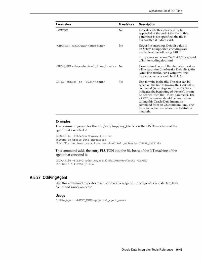
Alphabetic List of ODI Tools
Oracle Data Integrator Tools Reference A-43
ExamplesThe command generates the file /var/tmp/my_file.txt on the UNIX machine of the agent that executed it:
OdiOutFile -FILE=/var/tmp/my_file.txtWelcome to Oracle Data IntegratorThis file has been overwritten by <%=odiRef.getSession("SESS_NAME")%>
This command adds the entry PLUTON into the file hosts of the NT machine of the agent that executed it:
OdiOutFile -FILE=C:\winnt\system32\drivers\etc\hosts -APPEND195.10.10.6 PLUTON pluton
A.5.27 OdiPingAgentUse this command to perform a test on a given agent. If the agent is not started, this command raises an error.
UsageOdiPingAgent -AGENT_NAME=<physical_agent_name>
-APPEND No Indicates whether <Text> must be appended at the end of the file. If this parameter is not specified, the file is overwritten if it does exist.
-CHARSET_ENCODING=<encoding> No Target file encoding. Default value is ISO-8859-1. Supported encodings are available at the following URL:
http://java.sun.com/j2se/1.4.2/docs/guide/intl/encoding.doc.html
-XROW_SEP=<hexadecimal_line_break> No Hexadecimal code of the character used as a line separator (line break). Defaults to 0A (Unix line break). For a windows line break, the value should be 0D0A.
CR/LF <text> or -TEXT=<text> Yes Text to write in the file. This text can be typed on the line following the OdiOutFile command (A carriage return - CR/LF - indicates the beginning of the text), or can be defined with the -TEXT parameter. The -TEXT parameter should be used when calling this Oracle Data Integrator command from an OS command line. The text can contain variables or substitution methods.
Parameters Mandatory Description
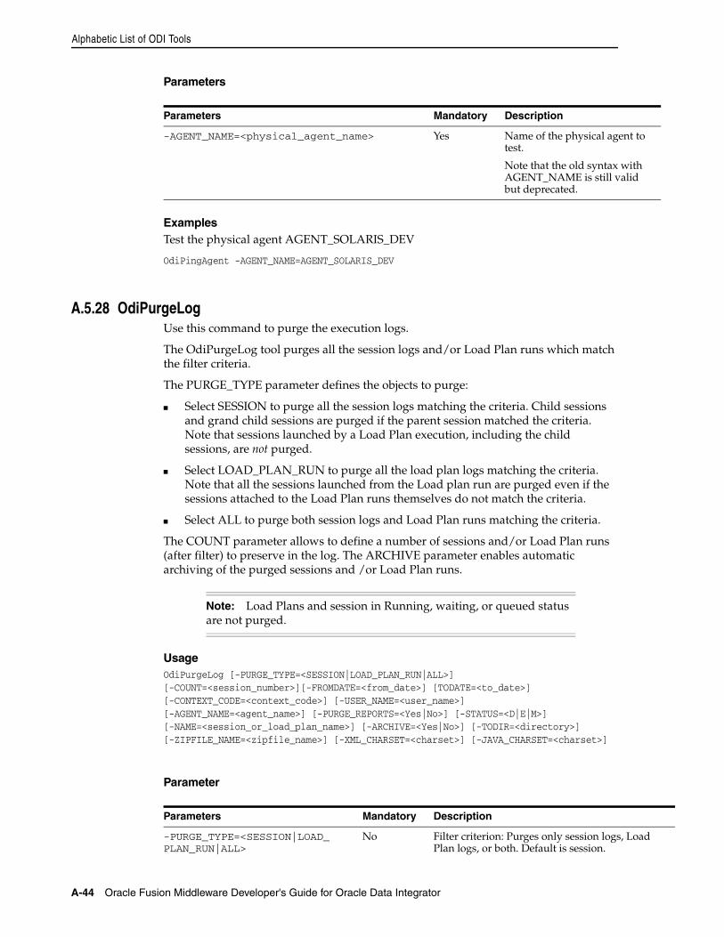
Alphabetic List of ODI Tools
A-44 Oracle Fusion Middleware Developer's Guide for Oracle Data Integrator
Parameters
ExamplesTest the physical agent AGENT_SOLARIS_DEV
OdiPingAgent -AGENT_NAME=AGENT_SOLARIS_DEV
A.5.28 OdiPurgeLogUse this command to purge the execution logs.
The OdiPurgeLog tool purges all the session logs and/or Load Plan runs which match the filter criteria.
The PURGE_TYPE parameter defines the objects to purge:
■ Select SESSION to purge all the session logs matching the criteria. Child sessions and grand child sessions are purged if the parent session matched the criteria. Note that sessions launched by a Load Plan execution, including the child sessions, are not purged.
■ Select LOAD_PLAN_RUN to purge all the load plan logs matching the criteria. Note that all the sessions launched from the Load plan run are purged even if the sessions attached to the Load Plan runs themselves do not match the criteria.
■ Select ALL to purge both session logs and Load Plan runs matching the criteria.
The COUNT parameter allows to define a number of sessions and/or Load Plan runs (after filter) to preserve in the log. The ARCHIVE parameter enables automatic archiving of the purged sessions and /or Load Plan runs.
UsageOdiPurgeLog [-PURGE_TYPE=<SESSION|LOAD_PLAN_RUN|ALL>][-COUNT=<session_number>][-FROMDATE=<from_date>] [TODATE=<to_date>][-CONTEXT_CODE=<context_code>] [-USER_NAME=<user_name>][-AGENT_NAME=<agent_name>] [-PURGE_REPORTS=<Yes|No>] [-STATUS=<D|E|M>][-NAME=<session_or_load_plan_name>] [-ARCHIVE=<Yes|No>] [-TODIR=<directory>][-ZIPFILE_NAME=<zipfile_name>] [-XML_CHARSET=<charset>] [-JAVA_CHARSET=<charset>]
Parameter
Parameters Mandatory Description
-AGENT_NAME=<physical_agent_name> Yes Name of the physical agent to test.
Note that the old syntax with AGENT_NAME is still valid but deprecated.
Note: Load Plans and session in Running, waiting, or queued status are not purged.
Parameters Mandatory Description
-PURGE_TYPE=<SESSION|LOAD_PLAN_RUN|ALL>
No Filter criterion: Purges only session logs, Load Plan logs, or both. Default is session.
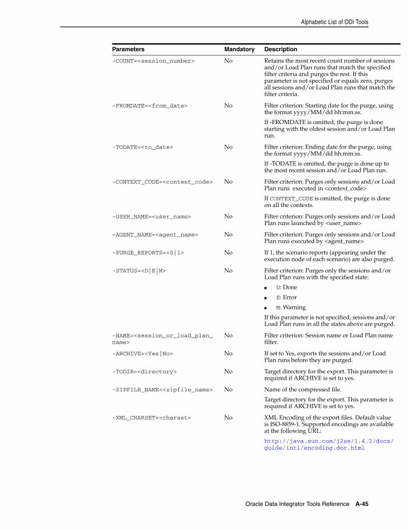
Alphabetic List of ODI Tools
Oracle Data Integrator Tools Reference A-45
-COUNT=<session_number> No Retains the most recent count number of sessions and/or Load Plan runs that match the specified filter criteria and purges the rest. If this parameter is not specified or equals zero, purges all sessions and/or Load Plan runs that match the filter criteria.
-FROMDATE=<from_date> No Filter criterion: Starting date for the purge, using the format yyyy/MM/dd hh:mm:ss.
If -FROMDATE is omitted, the purge is done starting with the oldest session and/or Load Plan run.
-TODATE=<to_date> No Filter criterion: Ending date for the purge, using the format yyyy/MM/dd hh:mm:ss.
If -TODATE is omitted, the purge is done up to the most recent session and/or Load Plan run.
-CONTEXT_CODE=<context_code> No Filter criterion: Purges only sessions and/or Load Plan runs executed in <context_code>
If CONTEXT_CODE is omitted, the purge is done on all the contexts.
-USER_NAME=<user_name> No Filter criterion: Purges only sessions and/or Load Plan runs launched by <user_name>
-AGENT_NAME=<agent_name> No Filter criterion: Purges only sessions and/or Load Plan runs executed by <agent_name>
-PURGE_REPORTS=<0|1> No If 1, the scenario reports (appearing under the execution node of each scenario) are also purged.
-STATUS=<D|E|M> No Filter criterion: Purges only the sessions and/or Load Plan runs with the specified state:
■ D: Done
■ E: Error
■ M: Warning
If this parameter is not specified, sessions and/or Load Plan runs in all the states above are purged.
-NAME=<session_or_load_plan_name>
No Filter criterion: Session name or Load Plan name filter.
-ARCHIVE=<Yes|No> No If set to Yes, exports the sessions and/or Load Plan runs before they are purged.
-TODIR=<directory> No Target directory for the export. This parameter is required if ARCHIVE is set to yes.
-ZIPFILE_NAME=<zipfile_name> No Name of the compressed file.
Target directory for the export. This parameter is required if ARCHIVE is set to yes.
-XML_CHARSET=<charset> No XML Encoding of the export files. Default value is ISO-8859-1. Supported encodings are available at the following URL:
http://java.sun.com/j2se/1.4.2/docs/guide/intl/encoding.doc.html
Parameters Mandatory Description
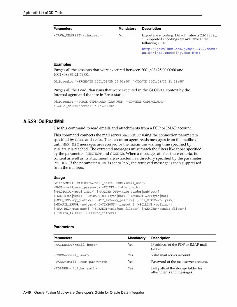
Alphabetic List of ODI Tools
A-46 Oracle Fusion Middleware Developer's Guide for Oracle Data Integrator
ExamplesPurges all the sessions that were executed between 2001/03/25 00:00:00 and 2001/08/31 21:59:00.
OdiPurgeLog "-FROMDATE=2001/03/25 00:00:00" "-TODATE=2001/08/31 21:59:00"
Purges all the Load Plan runs that were executed in the GLOBAL context by the Internal agent and that are in Error status.
OdiPurgeLog "-PURGE_TYPE=LOAD_PLAN_RUN" "-CONTEXT_CODE=GLOBAL" "-AGENT_NAME=Internal" "-STATUS=E"
A.5.29 OdiReadMailUse this command to read emails and attachments from a POP or IMAP account.
This command connects the mail server MAILHOST using the connection parameters specified by USER and PASS. The execution agent reads messages from the mailbox until MAX_MSG messages are received or the maximum waiting time specified by TIMEOUT is reached. The extracted messages must match the filters like those specified by the parameters SUBJECT and SENDER. When a message satisfies these criteria, its content as well as its attachment are extracted in a directory specified by the parameter FOLDER. If the parameter KEEP is set to "no", the retrieved message is then suppressed from the mailbox.
UsageOdiReadMail -MAILHOST=<mail_host> -USER=<mail_user>-PASS=<mail_user_password> -FOLDER=<folder_path>[-PROTOCOL=<pop3|imap>] [-FOLDER_OPT=<none|sender|subject>] [-KEEP=<no|yes>] [-EXTRACT_MSG=<yes|no>] [-EXTRACT_ATT=<yes|no>][-MSG_PRF=<my_prefix>] [-ATT_PRF=<my_prefix>] [-USE_UCASE=<no|yes>][-NOMAIL_ERROR=<no|yes>] [-TIMEOUT=<timeout>] [-POLLINT=<pollint>][-MAX_MSG=<max_msg>] [-SUBJECT=<subject_filter>] [-SENDER=<sender_filter>][-TO=<to_filter>] [-CC=<cc_filter>]
Parameters
-JAVA_CHARSET=<charset> No Export file encoding. Default value is ISO8859_1. Supported encodings are available at the following URL:
http://java.sun.com/j2se/1.4.2/docs/guide/intl/encoding.doc.html
Parameters Mandatory Description
-MAILHOST=<mail_host> Yes IP address of the POP or IMAP mail server
-USER=<mail_user> Yes Valid mail server account.
-PASS=<mail_user_password> Yes Password of the mail server account.
-FOLDER=<folder_path> Yes Full path of the storage folder for attachments and messages
Parameters Mandatory Description
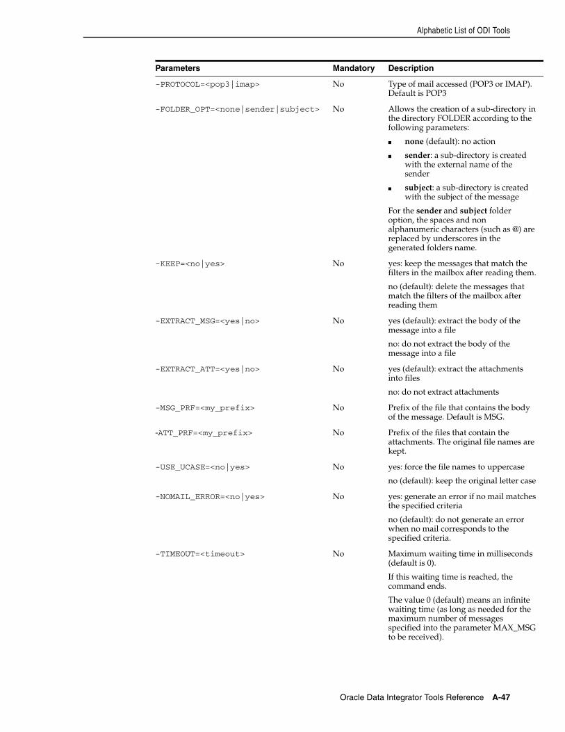
Alphabetic List of ODI Tools
Oracle Data Integrator Tools Reference A-47
-PROTOCOL=<pop3|imap> No Type of mail accessed (POP3 or IMAP). Default is POP3
-FOLDER_OPT=<none|sender|subject> No Allows the creation of a sub-directory in the directory FOLDER according to the following parameters:
■ none (default): no action
■ sender: a sub-directory is created with the external name of the sender
■ subject: a sub-directory is created with the subject of the message
For the sender and subject folder option, the spaces and non alphanumeric characters (such as @) are replaced by underscores in the generated folders name.
-KEEP=<no|yes> No yes: keep the messages that match the filters in the mailbox after reading them.
no (default): delete the messages that match the filters of the mailbox after reading them
-EXTRACT_MSG=<yes|no> No yes (default): extract the body of the message into a file
no: do not extract the body of the message into a file
-EXTRACT_ATT=<yes|no> No yes (default): extract the attachments into files
no: do not extract attachments
-MSG_PRF=<my_prefix> No Prefix of the file that contains the body of the message. Default is MSG.
-ATT_PRF=<my_prefix> No Prefix of the files that contain the attachments. The original file names are kept.
-USE_UCASE=<no|yes> No yes: force the file names to uppercase
no (default): keep the original letter case
-NOMAIL_ERROR=<no|yes> No yes: generate an error if no mail matches the specified criteria
no (default): do not generate an error when no mail corresponds to the specified criteria.
-TIMEOUT=<timeout> No Maximum waiting time in milliseconds (default is 0).
If this waiting time is reached, the command ends.
The value 0 (default) means an infinite waiting time (as long as needed for the maximum number of messages specified into the parameter MAX_MSG to be received).
Parameters Mandatory Description
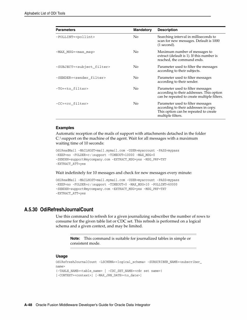
Alphabetic List of ODI Tools
A-48 Oracle Fusion Middleware Developer's Guide for Oracle Data Integrator
ExamplesAutomatic reception of the mails of support with attachments detached in the folder C:\support on the machine of the agent. Wait for all messages with a maximum waiting time of 10 seconds:
OdiReadMail -MAILHOST=mail.mymail.com -USER=myaccount -PASS=mypass-KEEP=no -FOLDER=c:\support -TIMEOUT=10000 [email protected] -EXTRACT_MSG=yes -MSG_PRF=TXT-EXTRACT_ATT=yes
Wait indefinitely for 10 messages and check for new messages every minute:
OdiReadMail -MAILHOST=mail.mymail.com -USER=myaccount -PASS=mypass-KEEP=no -FOLDER=c:\support -TIMEOUT=0 -MAX_MSG=10 [email protected] -EXTRACT_MSG=yes -MSG_PRF=TXT-EXTRACT_ATT=yes
A.5.30 OdiRefreshJournalCountUse this command to refresh for a given journalizing subscriber the number of rows to consume for the given table list or CDC set. This refresh is performed on a logical schema and a given context, and may be limited.
UsageOdiRefreshJournalCount -LSCHEMA=<logical_schema> -SUBSCRIBER_NAME=<subscriber_name>(-TABLE_NAME=<table_name> | -CDC_SET_NAME=<cdc set name>)[-CONTEXT=<context>] [-MAX_JRN_DATE=<to_date>]
-POLLINT=<pollint> No Searching interval in milliseconds to scan for new messages. Default is 1000 (1 second).
-MAX_MSG=<max_msg> No Maximum number of messages to extract (default is 1). If this number is reached, the command ends.
-SUBJECT=<subject_filter> No Parameter used to filter the messages according to their subjects.
-SENDER=<sender_filter> No Parameter used to filter messages according to their sender.
-TO=<to_filter> No Parameter used to filter messages according to their addresses. This option can be repeated to create multiple filters.
-CC=<cc_filter> No Parameter used to filter messages according to their addresses in copy. This option can be repeated to create multiple filters.
Note: This command is suitable for journalized tables in simple or consistent mode.
Parameters Mandatory Description
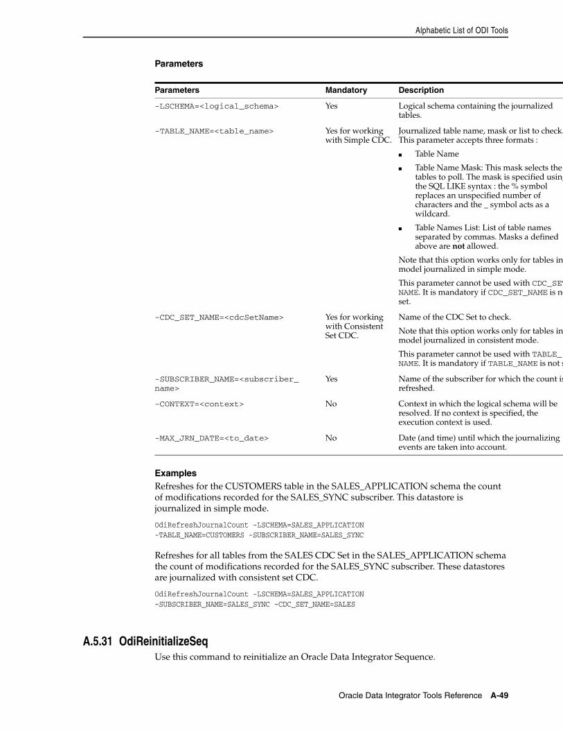
Alphabetic List of ODI Tools
Oracle Data Integrator Tools Reference A-49
Parameters
ExamplesRefreshes for the CUSTOMERS table in the SALES_APPLICATION schema the count of modifications recorded for the SALES_SYNC subscriber. This datastore is journalized in simple mode.
OdiRefreshJournalCount -LSCHEMA=SALES_APPLICATION-TABLE_NAME=CUSTOMERS -SUBSCRIBER_NAME=SALES_SYNC
Refreshes for all tables from the SALES CDC Set in the SALES_APPLICATION schema the count of modifications recorded for the SALES_SYNC subscriber. These datastores are journalized with consistent set CDC.
OdiRefreshJournalCount -LSCHEMA=SALES_APPLICATION-SUBSCRIBER_NAME=SALES_SYNC -CDC_SET_NAME=SALES
A.5.31 OdiReinitializeSeqUse this command to reinitialize an Oracle Data Integrator Sequence.
Parameters Mandatory Description
-LSCHEMA=<logical_schema> Yes Logical schema containing the journalized tables.
-TABLE_NAME=<table_name> Yes for working with Simple CDC.
Journalized table name, mask or list to check.This parameter accepts three formats :
■ Table Name
■ Table Name Mask: This mask selects the tables to poll. The mask is specified usingthe SQL LIKE syntax : the % symbol replaces an unspecified number of characters and the _ symbol acts as a wildcard.
■ Table Names List: List of table names separated by commas. Masks a defined above are not allowed.
Note that this option works only for tables in model journalized in simple mode.
This parameter cannot be used with CDC_SETNAME. It is mandatory if CDC_SET_NAME is noset.
-CDC_SET_NAME=<cdcSetName> Yes for working with Consistent Set CDC.
Name of the CDC Set to check.
Note that this option works only for tables in model journalized in consistent mode.
This parameter cannot be used with TABLE_NAME. It is mandatory if TABLE_NAME is not s
-SUBSCRIBER_NAME=<subscriber_name>
Yes Name of the subscriber for which the count isrefreshed.
-CONTEXT=<context> No Context in which the logical schema will be resolved. If no context is specified, the execution context is used.
-MAX_JRN_DATE=<to_date> No Date (and time) until which the journalizing events are taken into account.
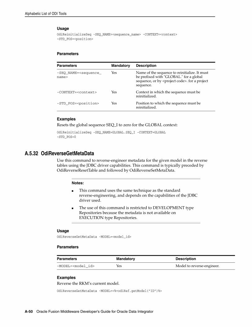
Alphabetic List of ODI Tools
A-50 Oracle Fusion Middleware Developer's Guide for Oracle Data Integrator
UsageOdiReinitializeSeq -SEQ_NAME=<sequence_name> -CONTEXT=<context>-STD_POS=<position>
Parameters
ExamplesResets the global sequence SEQ_I to zero for the GLOBAL context:
OdiReinitializeSeq -SEQ_NAME=GLOBAL.SEQ_I -CONTEXT=GLOBAL-STD_POS=0
A.5.32 OdiReverseGetMetaDataUse this command to reverse-engineer metadata for the given model in the reverse tables using the JDBC driver capabilities. This command is typically preceded by OdiReverseResetTable and followed by OdiReverseSetMetaData.
UsageOdiReverseGetMetaData -MODEL=<model_id>
Parameters
ExamplesReverse the RKM’s current model.
OdiReverseGetMetaData -MODEL=<%=odiRef.getModel("ID")%>
Parameters Mandatory Description
-SEQ_NAME=<sequence_name>
Yes Name of the sequence to reinitialize. It must be prefixed with "GLOBAL." for a global sequence, or by <project code>. for a project sequence.
-CONTEXT=<context> Yes Context in which the sequence must be reinitialized.
-STD_POS=<position> Yes Position to which the sequence must be reinitialized.
Notes:
■ This command uses the same technique as the standard reverse-engineering, and depends on the capabilities of the JDBC driver used.
■ The use of this command is restricted to DEVELOPMENT type Repositories because the metadata is not available on EXECUTION type Repositories.
Parameters Mandatory Description
-MODEL=<model_id> Yes Model to reverse-engineer.
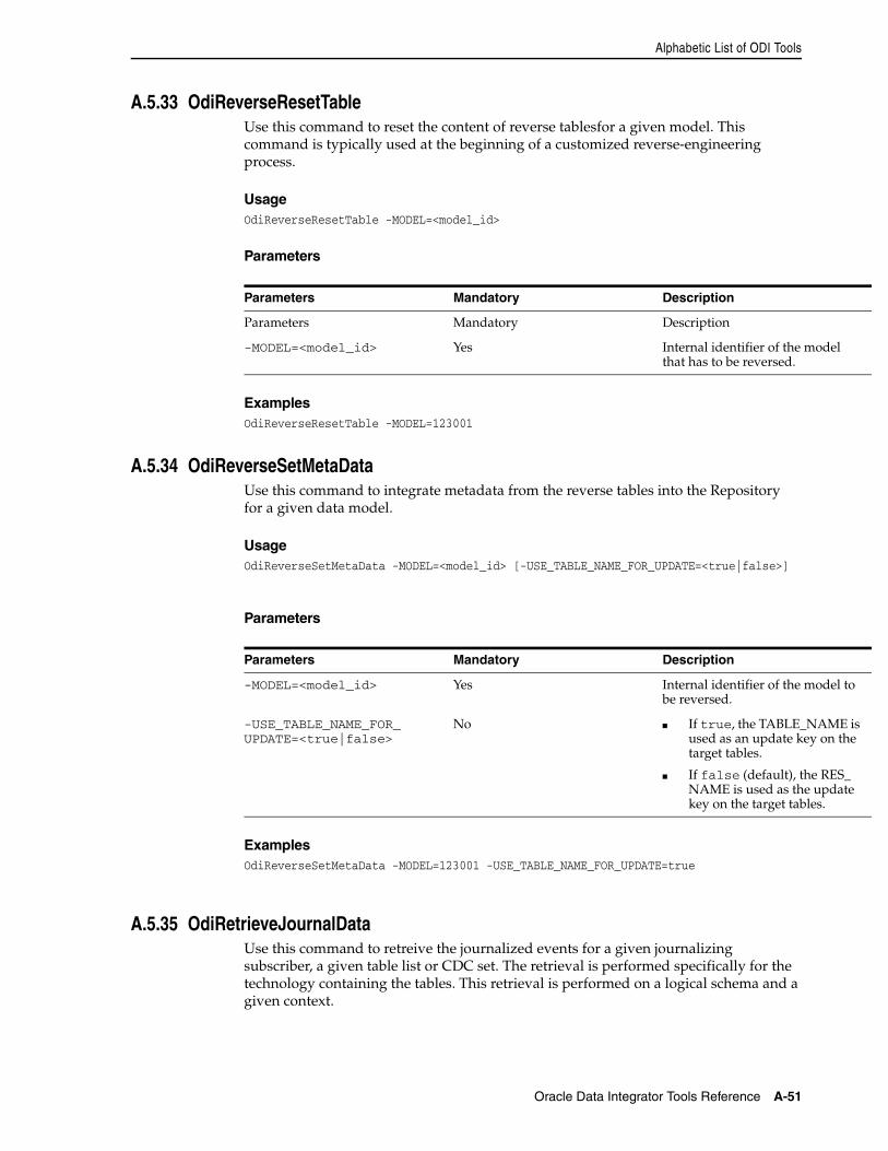
Alphabetic List of ODI Tools
Oracle Data Integrator Tools Reference A-51
A.5.33 OdiReverseResetTableUse this command to reset the content of reverse tablesfor a given model. This command is typically used at the beginning of a customized reverse-engineering process.
UsageOdiReverseResetTable -MODEL=<model_id>
Parameters
ExamplesOdiReverseResetTable -MODEL=123001
A.5.34 OdiReverseSetMetaDataUse this command to integrate metadata from the reverse tables into the Repository for a given data model.
UsageOdiReverseSetMetaData -MODEL=<model_id> [-USE_TABLE_NAME_FOR_UPDATE=<true|false>]
Parameters
ExamplesOdiReverseSetMetaData -MODEL=123001 -USE_TABLE_NAME_FOR_UPDATE=true
A.5.35 OdiRetrieveJournalDataUse this command to retreive the journalized events for a given journalizing subscriber, a given table list or CDC set. The retrieval is performed specifically for the technology containing the tables. This retrieval is performed on a logical schema and a given context.
Parameters Mandatory Description
Parameters Mandatory Description
-MODEL=<model_id> Yes Internal identifier of the model that has to be reversed.
Parameters Mandatory Description
-MODEL=<model_id> Yes Internal identifier of the model to be reversed.
-USE_TABLE_NAME_FOR_UPDATE=<true|false>
No ■ If true, the TABLE_NAME is used as an update key on the target tables.
■ If false (default), the RES_NAME is used as the update key on the target tables.
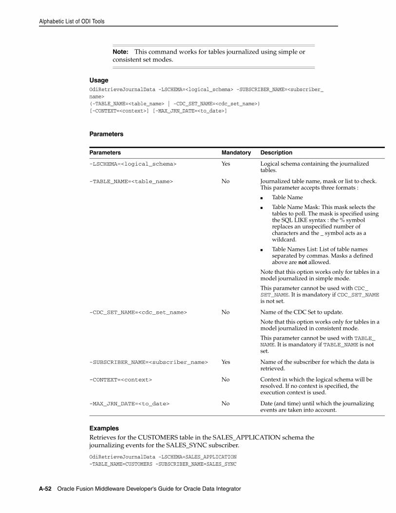
Alphabetic List of ODI Tools
A-52 Oracle Fusion Middleware Developer's Guide for Oracle Data Integrator
UsageOdiRetrieveJournalData -LSCHEMA=<logical_schema> -SUBSCRIBER_NAME=<subscriber_name> (-TABLE_NAME=<table_name> | -CDC_SET_NAME=<cdc_set_name>)[-CONTEXT=<context>] [-MAX_JRN_DATE=<to_date>]
Parameters
ExamplesRetrieves for the CUSTOMERS table in the SALES_APPLICATION schema the journalizing events for the SALES_SYNC subscriber.
OdiRetrieveJournalData -LSCHEMA=SALES_APPLICATION-TABLE_NAME=CUSTOMERS -SUBSCRIBER_NAME=SALES_SYNC
Note: This command works for tables journalized using simple or consistent set modes.
Parameters Mandatory Description
-LSCHEMA=<logical_schema> Yes Logical schema containing the journalized tables.
-TABLE_NAME=<table_name> No Journalized table name, mask or list to check. This parameter accepts three formats :
■ Table Name
■ Table Name Mask: This mask selects the tables to poll. The mask is specified using the SQL LIKE syntax : the % symbol replaces an unspecified number of characters and the _ symbol acts as a wildcard.
■ Table Names List: List of table names separated by commas. Masks a defined above are not allowed.
Note that this option works only for tables in a model journalized in simple mode.
This parameter cannot be used with CDC_SET_NAME. It is mandatory if CDC_SET_NAME is not set.
-CDC_SET_NAME=<cdc_set_name> No Name of the CDC Set to update.
Note that this option works only for tables in a model journalized in consistent mode.
This parameter cannot be used with TABLE_NAME. It is mandatory if TABLE_NAME is not set.
-SUBSCRIBER_NAME=<subscriber_name> Yes Name of the subscriber for which the data is retrieved.
-CONTEXT=<context> No Context in which the logical schema will be resolved. If no context is specified, the execution context is used.
-MAX_JRN_DATE=<to_date> No Date (and time) until which the journalizing events are taken into account.
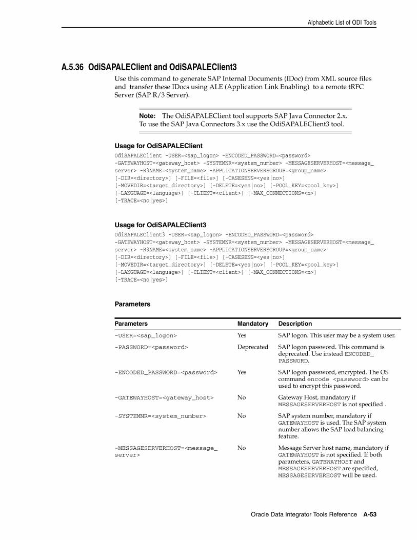
Alphabetic List of ODI Tools
Oracle Data Integrator Tools Reference A-53
A.5.36 OdiSAPALEClient and OdiSAPALEClient3Use this command to generate SAP Internal Documents (IDoc) from XML source files and transfer these IDocs using ALE (Application Link Enabling) to a remote tRFC Server (SAP R/3 Server).
Usage for OdiSAPALEClientOdiSAPALEClient -USER=<sap_logon> -ENCODED_PASSWORD=<password>-GATEWAYHOST=<gateway_host> -SYSTEMNR=<system_number> -MESSAGESERVERHOST=<message_server> -R3NAME=<system_name> -APPLICATIONSERVERSGROUP=<group_name>[-DIR=<directory>] [-FILE=<file>] [-CASESENS=<yes|no>][-MOVEDIR=<target_directory>] [-DELETE=<yes|no>] [-POOL_KEY=<pool_key>][-LANGUAGE=<language>] [-CLIENT=<client>] [-MAX_CONNECTIONS=<n>][-TRACE=<no|yes>]
Usage for OdiSAPALEClient3OdiSAPALEClient3 -USER=<sap_logon> -ENCODED_PASSWORD=<password>-GATEWAYHOST=<gateway_host> -SYSTEMNR=<system_number> -MESSAGESERVERHOST=<message_server> -R3NAME=<system_name> -APPLICATIONSERVERSGROUP=<group_name>[-DIR=<directory>] [-FILE=<file>] [-CASESENS=<yes|no>][-MOVEDIR=<target_directory>] [-DELETE=<yes|no>] [-POOL_KEY=<pool_key>][-LANGUAGE=<language>] [-CLIENT=<client>] [-MAX_CONNECTIONS=<n>][-TRACE=<no|yes>]
Parameters
Note: The OdiSAPALEClient tool supports SAP Java Connector 2.x. To use the SAP Java Connectors 3.x use the OdiSAPALEClient3 tool.
Parameters Mandatory Description
-USER=<sap_logon> Yes SAP logon. This user may be a system user.
-PASSWORD=<password> Deprecated SAP logon password. This command is deprecated. Use instead ENCODED_PASSWORD.
-ENCODED_PASSWORD=<password> Yes SAP logon password, encrypted. The OS command encode <password> can be used to encrypt this password.
-GATEWAYHOST=<gateway_host> No Gateway Host, mandatory if MESSAGESERVERHOST is not specified .
-SYSTEMNR=<system_number> No SAP system number, mandatory if GATEWAYHOST is used. The SAP system number allows the SAP load balancing feature.
-MESSAGESERVERHOST=<message_server>
No Message Server host name, mandatory if GATEWAYHOST is not specified. If both parameters, GATEWAYHOST and MESSAGESERVERHOST are specified, MESSAGESERVERHOST will be used.
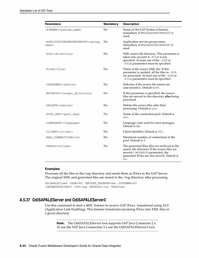
Alphabetic List of ODI Tools
A-54 Oracle Fusion Middleware Developer's Guide for Oracle Data Integrator
ExamplesProcesses all the files in the/sap directory and sends them as IDocs to the SAP Server. The original XML and generated files are stored in the /log directory after processing.
OdiSAPALEClient -USER=ODI -ENCODED_PASSWORD=xxx -SYSTEMNR=002-GATEWAYHOST=GW001 -DIR=/sap -MOVEDIR=/log -TRACE=yes
A.5.37 OdiSAPALEServer and OdiSAPALEServer3Use this command to start a tRFC listener to receive SAP IDocs transferred using ALE (Application Link Enabling). This listener transforms incoming IDocs into XML files in a given directory.
-R3NAME=<system_name> No Name of the SAP System (r3name), manadtory if MESSAGESERVERHOST is used.
-APPLICATIONSERVERSGROUP=<group_name>
No Application servers group name, manadtory if MESSAGESERVERHOST is used.
-DIR=<directory> No XML source file directory. This parameter is taken into account if -FILE is not specified. At least one of the -DIR or -FILE parameters must be specified.
-FILE=<file> No Name of the source XML file. If this parameter is omitted, all the files in -DIR are processed. At least one of the -DIR or -FILE parameters must be specified.
-CASESENS=<yes|no> No Indicates if the source file names are case-sensitive. Default is NO.
-MOVEDIR=<target_directory> No If this parameter is specified, the source files are moved to this directory after being processed.
-DELETE=<yes|no> No Deletes the source files after their processing. Default is yes.
-POOL_KEY=<pool_key> No Name of the connection pool. Default is ODI.
-LANGUAGE=<language> No Language code used for error messages. Default is EN.
-CLIENT=<client> No Client identifier. Default is 001.
-MAX_CONNECTIONS=<n> No Maximum number of connections in the pool. Default is 3.
-TRACE=<no|yes> No The generated IDoc files are archived in the source file directory. If the source files are moved (-MOVEDIR parameter), the generated IDocs are also moved. Default is no.
Note: The OdiSAPALEServer tool supports SAP Java Connector 2.x. To use the SAP Java Connectors 3.x use the OdiSAPALEServer3 tool.
Parameters Mandatory Description
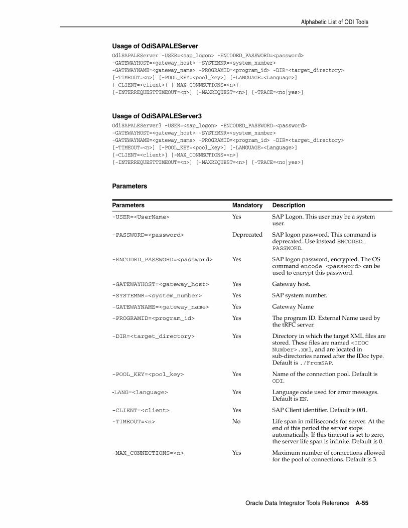
Alphabetic List of ODI Tools
Oracle Data Integrator Tools Reference A-55
Usage of OdiSAPALEServerOdiSAPALEServer -USER=<sap_logon> -ENCODED_PASSWORD=<password>-GATEWAYHOST=<gateway_host> -SYSTEMNR=<system_number>-GATEWAYNAME=<gateway_name> -PROGRAMID=<program_id> -DIR=<target_directory>[-TIMEOUT=<n>] [-POOL_KEY=<pool_key>] [-LANGUAGE=<Language>][-CLIENT=<client>] [-MAX_CONNECTIONS=<n>][-INTERREQUESTTIMEOUT=<n>] [-MAXREQUEST=<n>] [-TRACE=<no|yes>]
Usage of OdiSAPALEServer3OdiSAPALEServer3 -USER=<sap_logon> -ENCODED_PASSWORD=<password>-GATEWAYHOST=<gateway_host> -SYSTEMNR=<system_number>-GATEWAYNAME=<gateway_name> -PROGRAMID=<program_id> -DIR=<target_directory>[-TIMEOUT=<n>] [-POOL_KEY=<pool_key>] [-LANGUAGE=<Language>][-CLIENT=<client>] [-MAX_CONNECTIONS=<n>][-INTERREQUESTTIMEOUT=<n>] [-MAXREQUEST=<n>] [-TRACE=<no|yes>]
Parameters
Parameters Mandatory Description
-USER=<UserName> Yes SAP Logon. This user may be a system user.
-PASSWORD=<password> Deprecated SAP logon password. This command is deprecated. Use instead ENCODED_PASSWORD.
-ENCODED_PASSWORD=<password> Yes SAP logon password, encrypted. The OS command encode <password> can be used to encrypt this password.
-GATEWAYHOST=<gateway_host> Yes Gateway host.
-SYSTEMNR=<system_number> Yes SAP system number.
-GATEWAYNAME=<gateway_name> Yes Gateway Name
-PROGRAMID=<program_id> Yes The program ID. External Name used by the tRFC server.
-DIR=<target_directory> Yes Directory in which the target XML files are stored. These files are named <IDOC Number>.xml, and are located in sub-directories named after the IDoc type. Default is ./FromSAP.
-POOL_KEY=<pool_key> Yes Name of the connection pool. Default is ODI.
-LANG=<language> Yes Language code used for error messages. Default is EN.
-CLIENT=<client> Yes SAP Client identifier. Default is 001.
-TIMEOUT=<n> No Life span in milliseconds for server. At the end of this period the server stops automatically. If this timeout is set to zero, the server life span is infinite. Default is 0.
-MAX_CONNECTIONS=<n> Yes Maximum number of connections allowed for the pool of connections. Default is 3.
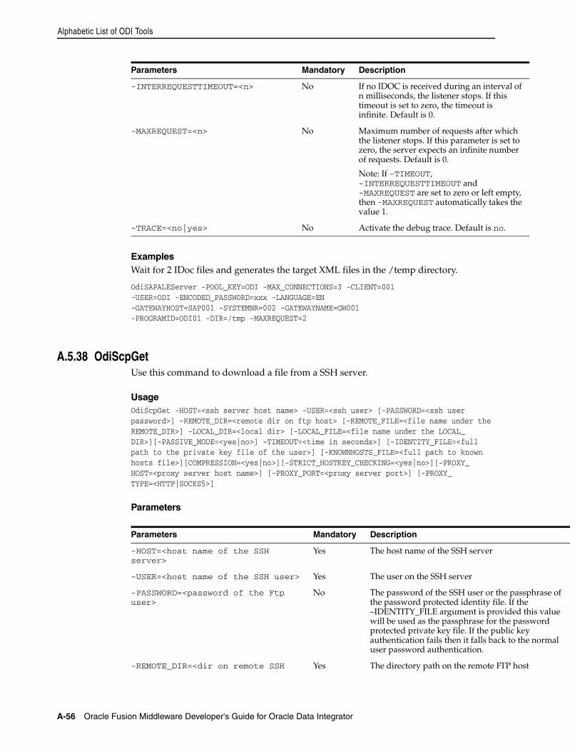
Alphabetic List of ODI Tools
A-56 Oracle Fusion Middleware Developer's Guide for Oracle Data Integrator
ExamplesWait for 2 IDoc files and generates the target XML files in the /temp directory.
OdiSAPALEServer -POOL_KEY=ODI -MAX_CONNECTIONS=3 -CLIENT=001-USER=ODI -ENCODED_PASSWORD=xxx -LANGUAGE=EN-GATEWAYHOST=SAP001 -SYSTEMNR=002 -GATEWAYNAME=GW001-PROGRAMID=ODI01 -DIR=/tmp -MAXREQUEST=2
A.5.38 OdiScpGetUse this command to download a file from a SSH server.
UsageOdiScpGet -HOST=<ssh server host name> -USER=<ssh user> [-PASSWORD=<ssh user password>] -REMOTE_DIR=<remote dir on ftp host> [-REMOTE_FILE=<file name under the REMOTE_DIR>] -LOCAL_DIR=<local dir> [-LOCAL_FILE=<file name under the LOCAL_DIR>][-PASSIVE_MODE=<yes|no>] -TIMEOUT=<time in seconds>] [-IDENTITY_FILE=<full path to the private key file of the user>] [-KNOWNHOSTS_FILE=<full path to known hosts file>][COMPRESSION=<yes|no>][-STRICT_HOSTKEY_CHECKING=<yes|no>][-PROXY_HOST=<proxy server host name>] [-PROXY_PORT=<proxy server port>] [-PROXY_TYPE=<HTTP|SOCKS5>]
Parameters
-INTERREQUESTTIMEOUT=<n> No If no IDOC is received during an interval of n milliseconds, the listener stops. If this timeout is set to zero, the timeout is infinite. Default is 0.
-MAXREQUEST=<n> No Maximum number of requests after which the listener stops. If this parameter is set to zero, the server expects an infinite number of requests. Default is 0.
Note: If -TIMEOUT, -INTERREQUESTTIMEOUT and -MAXREQUEST are set to zero or left empty, then -MAXREQUEST automatically takes the value 1.
-TRACE=<no|yes> No Activate the debug trace. Default is no.
Parameters Mandatory Description
-HOST=<host name of the SSH server>
Yes The host name of the SSH server
-USER=<host name of the SSH user> Yes The user on the SSH server
-PASSWORD=<password of the Ftp user>
No The password of the SSH user or the passphrase of the password protected identity file. If the –IDENTITY_FILE argument is provided this value will be used as the passphrase for the password protected private key file. If the public key authentication fails then it falls back to the normal user password authentication.
-REMOTE_DIR=<dir on remote SSH Yes The directory path on the remote FTP host
Parameters Mandatory Description
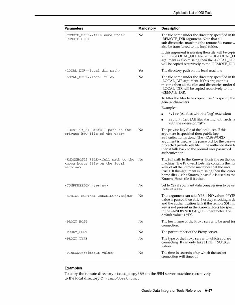
Alphabetic List of ODI Tools
Oracle Data Integrator Tools Reference A-57
ExamplesTo copy the remote directory /test_copy555 on the SSH server machine recursively to the local directory C:\temp\test_copy
-REMOTE_FILE=<file name under -REMOTE DIR>
No The file name under the directory specified in the-REMOTE_DIR argument. Note that all sub-directories matching the remote file name walso be transferred to the local folder.
If this argument is missing then file will be copiewith the -LOCAL_FILE file name. If -LOCAL_FILargument is also missing then the -LOCAL_DIR will be copied recursively to the -REMOTE_DIR
-LOCAL_DIR=<local dir path> Yes The directory path on the local machine
-LOCAL_FILE=<local file> No The file name under the directory specified in the-LOCAL_DIR argument. If this argument is missing then all the files and directories under th-LOCAL_DIR will be copied recursively to the -REMOTE_DIR.
To filter the files to be copied use * to specify the generic characters.
Examples:
■ *.log (All files with the "log" extension)
■ arch_*.lst (All files starting with arch_ anwith the extension "lst")
-IDENTITY_FILE=<full path to the private key file of the user>
No The private key file of the local user. If this argument is specified then public key authentication is done. The –PASSWORD argument is used as the password for the passwoprotected private key file. If the authentication fathen it falls back to the normal user password authentication.
-KNOWNHOSTS_FILE=<full path to the known hosts file on the local machine>
No The full path to the Known_Hosts file on the locamachine. The Known_Hosts file contains the hoskeys of all the Remote machines that the user trusts. If this argument is missing then the <userhome dir>/.ssh/Known_hosts file is used as theKnown_Hosts file if it exists.
-COMPRESSION=<yes|no> No Set to Yes if you want data compression to be useDefault is No.
-STRICT_HOSTKEY_CHECKING=<YES|NO> No This argument can take YES | NO values. If YESvalue is passed then strict hostkey checking is doand the authentication fails if the remote SSH hokey is not present in the Known Hosts file specifiin the –KNOWNHOSTS_FILE parameter. The default value is YES.
-PROXY_HOST No The host name of the Proxy server to be used forconnection.
-PROXY_PORT No The port number of the Proxy server.
-PROXY_TYPE No The type of the Proxy server to which you are connecting. It can only take HTTP | SOCKS5 values.
-TIMEOUT=<timeout value> No The time in seconds after which the socket connection will timeout.
Parameters Mandatory Description
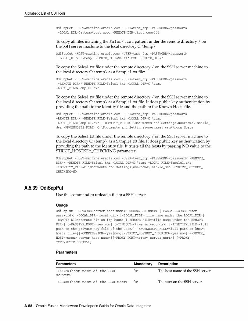
Alphabetic List of ODI Tools
A-58 Oracle Fusion Middleware Developer's Guide for Oracle Data Integrator
OdiScpGet -HOST=machine.oracle.com -USER=test_ftp -PASSWORD=<password> -LOCAL_DIR=C:\temp\test_copy -REMOTE_DIR=/test_copy555
To copy all files matching the Sales*.txt pattern under the remote directory / on the SSH server machine to the local directory C:\temp\
OdiScpGet -HOST=machine.oracle.com -USER=test_ftp -PASSWORD=<password> -LOCAL_DIR=C:\temp -REMOTE_FILE=Sales*.txt -REMOTE_DIR=/
To copy the Sales1.txt file under the remote directory / on the SSH server machine to the local directory C:\temp\ as a Sample1.txt file:
OdiScpGet -HOST=machine.oracle.com -USER=test_ftp -PASSWORD=<password> -REMOTE_DIR=/ REMOTE_FILE=Sales1.txt -LOCAL_DIR=C:\temp -LOCAL_FILE=Sample1.txt
To copy the Sales1.txt file under the remote directory / on the SSH server machine to the local directory C:\temp\ as a Sample1.txt file. It does public key authentication by providing the path to the Identity file and the path to the Known Hosts file.
OdiScpGet -HOST=machine.oracle.com -USER=test_ftp -PASSWORD=<password> -REMOTE_DIR=/ -REMOTE_FILE=Sales1.txt -LOCAL_DIR=C:\temp -LOCAL_FILE=Sample1.txt -IDENTITY_FILE=C:\Documents and Settings\username\.ssh\id_dsa -KNOWNHOSTS_FILE= C:\Documents and Settings\username\.ssh\Known_Hosts
To copy the Sales1.txt file under the remote directory / on the SSH server machine to the local directory C:\temp\ as a Sample1.txt file. It does public key authentication by providing the path to the Identity file. It trusts all the hosts by passing NO value to the STRICT_HOSTKEY_CHECKING parameter:
OdiScpGet -HOST=machine.oracle.com -USER=test_ftp -PASSWORD=<password> -REMOTE_DIR=/ -REMOTE_FILE=Sales1.txt -LOCAL_DIR=C:\temp -LOCAL_FILE=Sample1.txt -IDENTITY_FILE=C:\Documents and Settings\username\.ssh\id_dsa -STRICT_HOSTKEY_CHECKING=NO
A.5.39 OdiScpPutUse this command to upload a file to a SSH server.
UsageOdiScpPut -HOST=<SSHserver host name> -USER=<SSH user> [-PASSWORD=<SSH user password>] -LOCAL_DIR=<local dir> [-LOCAL_FILE=<file name under the LOCAL_DIR>] -REMOTE_DIR=<remote dir on ftp host> [-REMOTE_FILE=<file name under the REMOTE_DIR>] [-PASSIVE_MODE=<yes|no>] [-TIMEOUT=<time in seconds>] [-IDENTITY_FILE=<full path to the private key file of the user>][-KNOWNHOSTS_FILE=<full path to known hosts file>][-COMPRESSION=<yes|no>][-STRICT_HOSTKEY_CHECKING=<yes|no>] <-PROXY_HOST=<proxy server host name>][-PROXY_PORT=<proxy server port>] [-PROXY_TYPE=<HTTP|SOCKS5>]
Parameters
Parameters Mandatory Description
-HOST=<host name of the SSH server>
Yes The host name of the SSH server
-USER=<host name of the SSH user> Yes The user on the SSH server
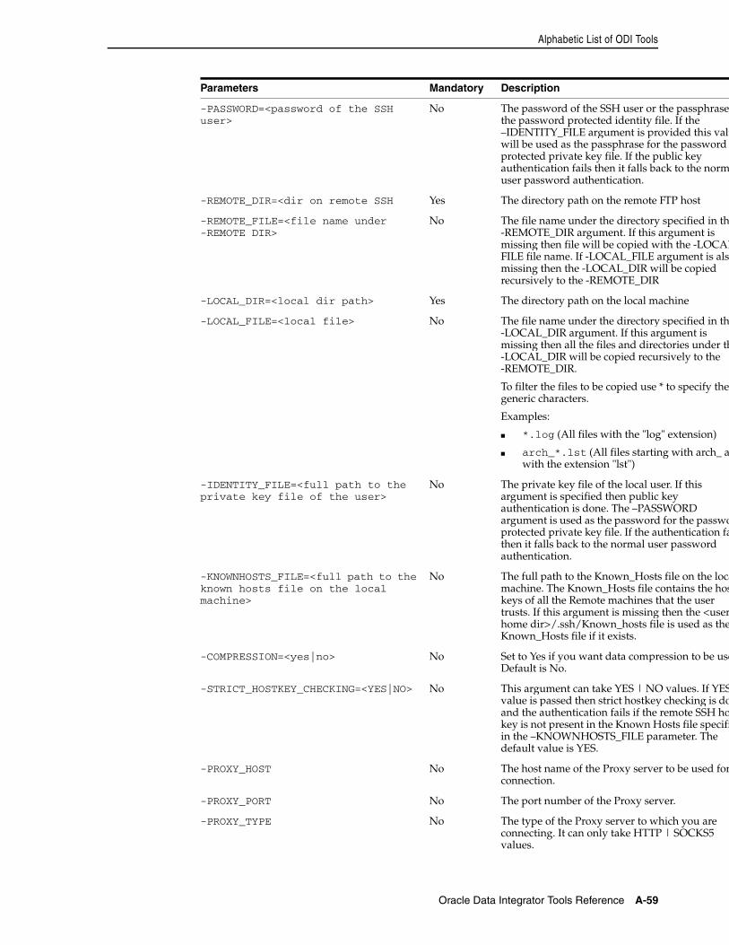
Alphabetic List of ODI Tools
Oracle Data Integrator Tools Reference A-59
-PASSWORD=<password of the SSH user>
No The password of the SSH user or the passphrase the password protected identity file. If the –IDENTITY_FILE argument is provided this valuwill be used as the passphrase for the password protected private key file. If the public key authentication fails then it falls back to the normuser password authentication.
-REMOTE_DIR=<dir on remote SSH Yes The directory path on the remote FTP host
-REMOTE_FILE=<file name under -REMOTE DIR>
No The file name under the directory specified in the-REMOTE_DIR argument. If this argument is missing then file will be copied with the -LOCALFILE file name. If -LOCAL_FILE argument is alsomissing then the -LOCAL_DIR will be copied recursively to the -REMOTE_DIR
-LOCAL_DIR=<local dir path> Yes The directory path on the local machine
-LOCAL_FILE=<local file> No The file name under the directory specified in the-LOCAL_DIR argument. If this argument is missing then all the files and directories under th-LOCAL_DIR will be copied recursively to the -REMOTE_DIR.
To filter the files to be copied use * to specify the generic characters.
Examples:
■ *.log (All files with the "log" extension)
■ arch_*.lst (All files starting with arch_ anwith the extension "lst")
-IDENTITY_FILE=<full path to the private key file of the user>
No The private key file of the local user. If this argument is specified then public key authentication is done. The –PASSWORD argument is used as the password for the passwoprotected private key file. If the authentication fathen it falls back to the normal user password authentication.
-KNOWNHOSTS_FILE=<full path to the known hosts file on the local machine>
No The full path to the Known_Hosts file on the locamachine. The Known_Hosts file contains the hoskeys of all the Remote machines that the user trusts. If this argument is missing then the <userhome dir>/.ssh/Known_hosts file is used as theKnown_Hosts file if it exists.
-COMPRESSION=<yes|no> No Set to Yes if you want data compression to be useDefault is No.
-STRICT_HOSTKEY_CHECKING=<YES|NO> No This argument can take YES | NO values. If YESvalue is passed then strict hostkey checking is doand the authentication fails if the remote SSH hokey is not present in the Known Hosts file specifiin the –KNOWNHOSTS_FILE parameter. The default value is YES.
-PROXY_HOST No The host name of the Proxy server to be used forconnection.
-PROXY_PORT No The port number of the Proxy server.
-PROXY_TYPE No The type of the Proxy server to which you are connecting. It can only take HTTP | SOCKS5 values.
Parameters Mandatory Description
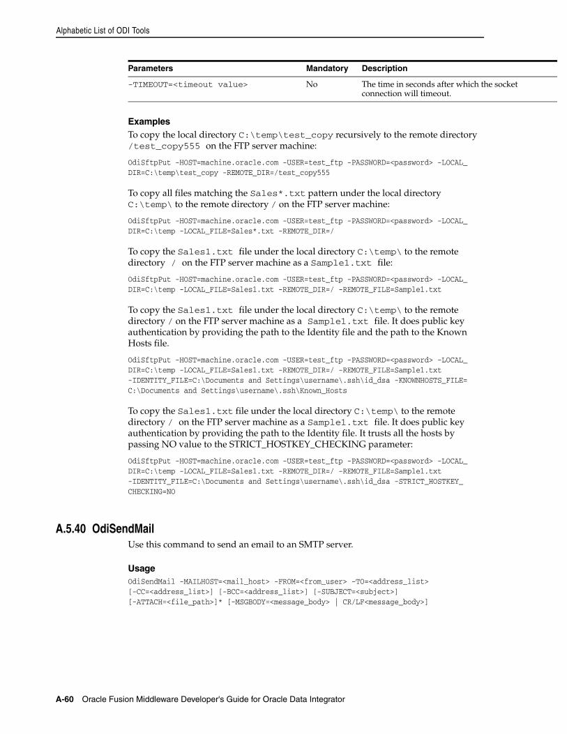
Alphabetic List of ODI Tools
A-60 Oracle Fusion Middleware Developer's Guide for Oracle Data Integrator
ExamplesTo copy the local directory C:\temp\test_copy recursively to the remote directory /test_copy555 on the FTP server machine:
OdiSftpPut -HOST=machine.oracle.com -USER=test_ftp -PASSWORD=<password> -LOCAL_DIR=C:\temp\test_copy -REMOTE_DIR=/test_copy555
To copy all files matching the Sales*.txt pattern under the local directory C:\temp\ to the remote directory / on the FTP server machine:
OdiSftpPut -HOST=machine.oracle.com -USER=test_ftp -PASSWORD=<password> -LOCAL_DIR=C:\temp -LOCAL_FILE=Sales*.txt -REMOTE_DIR=/
To copy the Sales1.txt file under the local directory C:\temp\ to the remote directory / on the FTP server machine as a Sample1.txt file:
OdiSftpPut -HOST=machine.oracle.com -USER=test_ftp -PASSWORD=<password> -LOCAL_DIR=C:\temp -LOCAL_FILE=Sales1.txt -REMOTE_DIR=/ -REMOTE_FILE=Sample1.txt
To copy the Sales1.txt file under the local directory C:\temp\ to the remote directory / on the FTP server machine as a Sample1.txt file. It does public key authentication by providing the path to the Identity file and the path to the Known Hosts file.
OdiSftpPut -HOST=machine.oracle.com -USER=test_ftp -PASSWORD=<password> -LOCAL_DIR=C:\temp -LOCAL_FILE=Sales1.txt -REMOTE_DIR=/ -REMOTE_FILE=Sample1.txt -IDENTITY_FILE=C:\Documents and Settings\username\.ssh\id_dsa -KNOWNHOSTS_FILE= C:\Documents and Settings\username\.ssh\Known_Hosts
To copy the Sales1.txt file under the local directory C:\temp\ to the remote directory / on the FTP server machine as a Sample1.txt file. It does public key authentication by providing the path to the Identity file. It trusts all the hosts by passing NO value to the STRICT_HOSTKEY_CHECKING parameter:
OdiSftpPut -HOST=machine.oracle.com -USER=test_ftp -PASSWORD=<password> -LOCAL_DIR=C:\temp -LOCAL_FILE=Sales1.txt -REMOTE_DIR=/ -REMOTE_FILE=Sample1.txt -IDENTITY_FILE=C:\Documents and Settings\username\.ssh\id_dsa -STRICT_HOSTKEY_CHECKING=NO
A.5.40 OdiSendMailUse this command to send an email to an SMTP server.
UsageOdiSendMail -MAILHOST=<mail_host> -FROM=<from_user> -TO=<address_list>[-CC=<address_list>] [-BCC=<address_list>] [-SUBJECT=<subject>][-ATTACH=<file_path>]* [-MSGBODY=<message_body> | CR/LF<message_body>]
-TIMEOUT=<timeout value> No The time in seconds after which the socket connection will timeout.
Parameters Mandatory Description
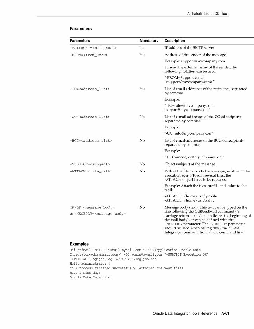
Alphabetic List of ODI Tools
Oracle Data Integrator Tools Reference A-61
Parameters
ExamplesOdiSendMail -MAILHOST=mail.mymail.com "-FROM=Application Oracle DataIntegrator<[email protected]>" [email protected] "-SUBJECT=Execution OK"-ATTACH=C:\log\job.log -ATTACH=C:\log\job.badHello Administrator !Your process finished successfully. Attached are your files.Have a nice day!Oracle Data Integrator.
Parameters Mandatory Description
-MAILHOST=<mail_host> Yes IP address of the SMTP server
-FROM=<from_user> Yes Address of the sender of the message.
Example: [email protected]
To send the external name of the sender, the following notation can be used:
"-FROM=Support center <[email protected]>"
-TO=<address_list> Yes List of email addresses of the recipients, separated by commas.
Example:
"[email protected], [email protected]"
-CC=<address_list> No List of e-mail addresses of the CC-ed recipients separated by commas.
Example:
-BCC=<address_list> No List of email-addresses of the BCC-ed recipients, separated by commas.
Example:
-SUBJECT=<subject> No Object (subject) of the message.
-ATTACH=<file_path> No Path of the file to join to the message, relative to the execution agent. To join several files, the -ATTACH=... just have to be repeated.
Example: Attach the files .profile and .cshrc to the mail:
-ATTACH=/home/usr/.profile -ATTACH=/home/usr/.cshrc
CR/LF <message_body>
or -MSGBODY=<message_body>
No Message body (text). This text can be typed on the line following the OdiSendMail command (A carriage return - CR/LF - indicates the beginning of the mail body), or can be defined with the -MSGBODY parameter. The -MSGBODY parameter should be used when calling this Oracle Data Integrator command from an OS command line.
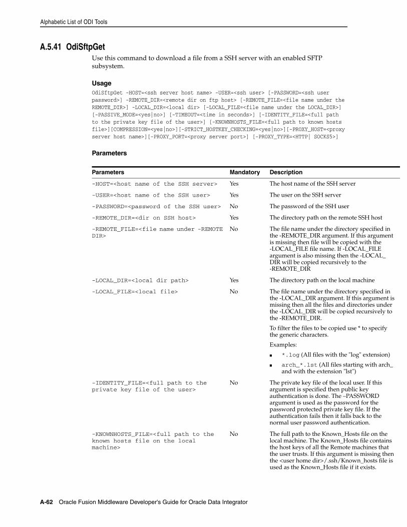
Alphabetic List of ODI Tools
A-62 Oracle Fusion Middleware Developer's Guide for Oracle Data Integrator
A.5.41 OdiSftpGetUse this command to download a file from a SSH server with an enabled SFTP subsystem.
UsageOdiSftpGet -HOST=<ssh server host name> -USER=<ssh user> [-PASSWORD=<ssh user password>] -REMOTE_DIR=<remote dir on ftp host> [-REMOTE_FILE=<file name under the REMOTE_DIR>] -LOCAL_DIR=<local dir> [-LOCAL_FILE=<file name under the LOCAL_DIR>] [-PASSIVE_MODE=<yes|no>] [-TIMEOUT=<time in seconds>] [-IDENTITY_FILE=<full path to the private key file of the user>] [-KNOWNHOSTS_FILE=<full path to known hosts file>][COMPRESSION=<yes|no>][-STRICT_HOSTKEY_CHECKING=<yes|no>][-PROXY_HOST=<proxy server host name>][-PROXY_PORT=<proxy server port>] [-PROXY_TYPE=<HTTP| SOCKS5>]
Parameters
Parameters Mandatory Description
-HOST=<host name of the SSH server> Yes The host name of the SSH server
-USER=<host name of the SSH user> Yes The user on the SSH server
-PASSWORD=<password of the SSH user> No The password of the SSH user
-REMOTE_DIR=<dir on SSH host> Yes The directory path on the remote SSH host
-REMOTE_FILE=<file name under -REMOTE DIR>
No The file name under the directory specified in the -REMOTE_DIR argument. If this argument is missing then file will be copied with the -LOCAL_FILE file name. If -LOCAL_FILE argument is also missing then the -LOCAL_DIR will be copied recursively to the -REMOTE_DIR
-LOCAL_DIR=<local dir path> Yes The directory path on the local machine
-LOCAL_FILE=<local file> No The file name under the directory specified in the -LOCAL_DIR argument. If this argument is missing then all the files and directories under the -LOCAL_DIR will be copied recursively to the -REMOTE_DIR.
To filter the files to be copied use * to specify the generic characters.
Examples:
■ *.log (All files with the "log" extension)
■ arch_*.lst (All files starting with arch_ and with the extension "lst")
-IDENTITY_FILE=<full path to the private key file of the user>
No The private key file of the local user. If this argument is specified then public key authentication is done. The –PASSWORD argument is used as the password for the password protected private key file. If the authentication fails then it falls back to the normal user password authentication.
-KNOWNHOSTS_FILE=<full path to the known hosts file on the local machine>
No The full path to the Known_Hosts file on the local machine. The Known_Hosts file contains the host keys of all the Remote machines that the user trusts. If this argument is missing then the <user home dir>/.ssh/Known_hosts file is used as the Known_Hosts file if it exists.
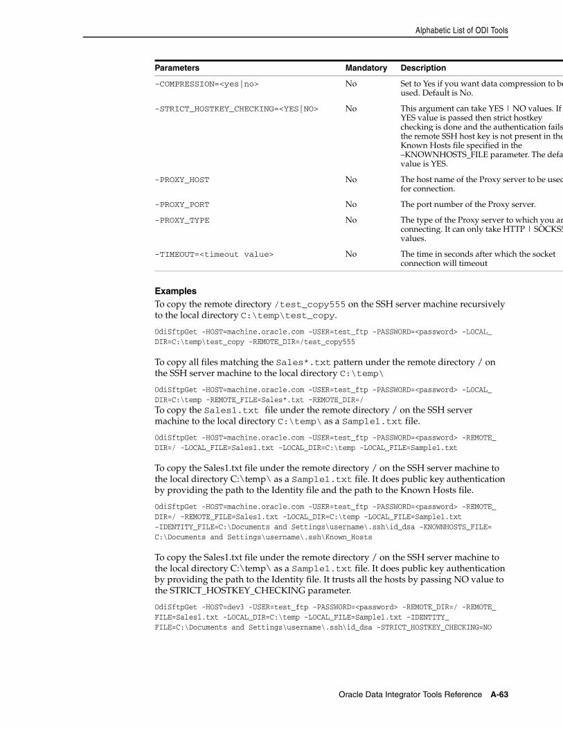
Alphabetic List of ODI Tools
Oracle Data Integrator Tools Reference A-63
ExamplesTo copy the remote directory /test_copy555 on the SSH server machine recursively to the local directory C:\temp\test_copy.
OdiSftpGet -HOST=machine.oracle.com -USER=test_ftp -PASSWORD=<password> -LOCAL_DIR=C:\temp\test_copy -REMOTE_DIR=/test_copy555
To copy all files matching the Sales*.txt pattern under the remote directory / on the SSH server machine to the local directory C:\temp\
OdiSftpGet -HOST=machine.oracle.com -USER=test_ftp -PASSWORD=<password> -LOCAL_DIR=C:\temp -REMOTE_FILE=Sales*.txt -REMOTE_DIR=/To copy the Sales1.txt file under the remote directory / on the SSH server machine to the local directory C:\temp\ as a Sample1.txt file.
OdiSftpGet -HOST=machine.oracle.com -USER=test_ftp -PASSWORD=<password> -REMOTE_DIR=/ -LOCAL_FILE=Sales1.txt -LOCAL_DIR=C:\temp -LOCAL_FILE=Sample1.txt
To copy the Sales1.txt file under the remote directory / on the SSH server machine to the local directory C:\temp\ as a Sample1.txt file. It does public key authentication by providing the path to the Identity file and the path to the Known Hosts file.
OdiSftpGet -HOST=machine.oracle.com -USER=test_ftp -PASSWORD=<password> -REMOTE_DIR=/ -REMOTE_FILE=Sales1.txt -LOCAL_DIR=C:\temp -LOCAL_FILE=Sample1.txt -IDENTITY_FILE=C:\Documents and Settings\username\.ssh\id_dsa -KNOWNHOSTS_FILE= C:\Documents and Settings\username\.ssh\Known_Hosts
To copy the Sales1.txt file under the remote directory / on the SSH server machine to the local directory C:\temp\ as a Sample1.txt file. It does public key authentication by providing the path to the Identity file. It trusts all the hosts by passing NO value to the STRICT_HOSTKEY_CHECKING parameter.
OdiSftpGet -HOST=dev3 -USER=test_ftp -PASSWORD=<password> -REMOTE_DIR=/ -REMOTE_FILE=Sales1.txt -LOCAL_DIR=C:\temp -LOCAL_FILE=Sample1.txt -IDENTITY_FILE=C:\Documents and Settings\username\.ssh\id_dsa -STRICT_HOSTKEY_CHECKING=NO
-COMPRESSION=<yes|no> No Set to Yes if you want data compression to beused. Default is No.
-STRICT_HOSTKEY_CHECKING=<YES|NO> No This argument can take YES | NO values. If YES value is passed then strict hostkey checking is done and the authentication fails the remote SSH host key is not present in theKnown Hosts file specified in the –KNOWNHOSTS_FILE parameter. The defauvalue is YES.
-PROXY_HOST No The host name of the Proxy server to be usedfor connection.
-PROXY_PORT No The port number of the Proxy server.
-PROXY_TYPE No The type of the Proxy server to which you arconnecting. It can only take HTTP | SOCKS5values.
-TIMEOUT=<timeout value> No The time in seconds after which the socket connection will timeout
Parameters Mandatory Description
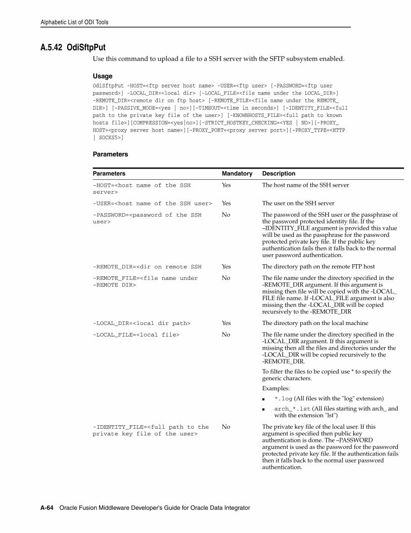
Alphabetic List of ODI Tools
A-64 Oracle Fusion Middleware Developer's Guide for Oracle Data Integrator
A.5.42 OdiSftpPutUse this command to upload a file to a SSH server with the SFTP subsystem enabled.
UsageOdiSftpPut -HOST=<ftp server host name> -USER=<ftp user> [-PASSWORD=<ftp user password>] -LOCAL_DIR=<local dir> [-LOCAL_FILE=<file name under the LOCAL_DIR>] -REMOTE_DIR=<remote dir on ftp host> [-REMOTE_FILE=<file name under the REMOTE_DIR>] [-PASSIVE_MODE=<yes | no>][-TIMEOUT=<time in seconds>] [-IDENTITY_FILE=<full path to the private key file of the user>] [-KNOWNHOSTS_FILE=<full path to known hosts file>][COMPRESSION=<yes|no>][-STRICT_HOSTKEY_CHECKING=<YES | NO>][-PROXY_HOST=<proxy server host name>][-PROXY_PORT=<proxy server port>][-PROXY_TYPE=<HTTP | SOCKS5>]
Parameters
Parameters Mandatory Description
-HOST=<host name of the SSH server>
Yes The host name of the SSH server
-USER=<host name of the SSH user> Yes The user on the SSH server
-PASSWORD=<password of the SSH user>
No The password of the SSH user or the passphrase of the password protected identity file. If the –IDENTITY_FILE argument is provided this value will be used as the passphrase for the password protected private key file. If the public key authentication fails then it falls back to the normal user password authentication.
-REMOTE_DIR=<dir on remote SSH Yes The directory path on the remote FTP host
-REMOTE_FILE=<file name under -REMOTE DIR>
No The file name under the directory specified in the -REMOTE_DIR argument. If this argument is missing then file will be copied with the -LOCAL_FILE file name. If -LOCAL_FILE argument is also missing then the -LOCAL_DIR will be copied recursively to the -REMOTE_DIR
-LOCAL_DIR=<local dir path> Yes The directory path on the local machine
-LOCAL_FILE=<local file> No The file name under the directory specified in the -LOCAL_DIR argument. If this argument is missing then all the files and directories under the -LOCAL_DIR will be copied recursively to the -REMOTE_DIR.
To filter the files to be copied use * to specify the generic characters.
Examples:
■ *.log (All files with the "log" extension)
■ arch_*.lst (All files starting with arch_ and with the extension "lst")
-IDENTITY_FILE=<full path to the private key file of the user>
No The private key file of the local user. If this argument is specified then public key authentication is done. The –PASSWORD argument is used as the password for the password protected private key file. If the authentication fails then it falls back to the normal user password authentication.
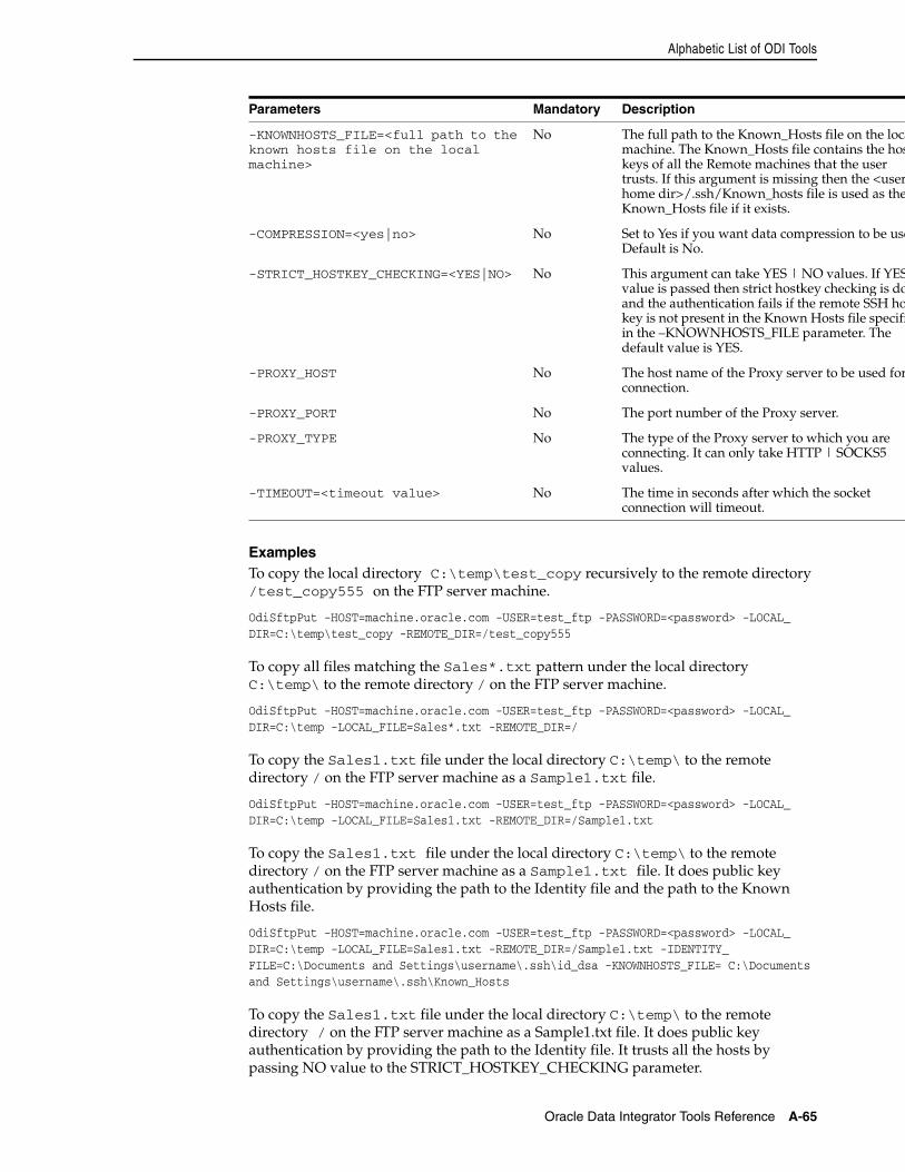
Alphabetic List of ODI Tools
Oracle Data Integrator Tools Reference A-65
ExamplesTo copy the local directory C:\temp\test_copy recursively to the remote directory /test_copy555 on the FTP server machine.
OdiSftpPut -HOST=machine.oracle.com -USER=test_ftp -PASSWORD=<password> -LOCAL_DIR=C:\temp\test_copy -REMOTE_DIR=/test_copy555
To copy all files matching the Sales*.txt pattern under the local directory C:\temp\ to the remote directory / on the FTP server machine.
OdiSftpPut -HOST=machine.oracle.com -USER=test_ftp -PASSWORD=<password> -LOCAL_DIR=C:\temp -LOCAL_FILE=Sales*.txt -REMOTE_DIR=/
To copy the Sales1.txt file under the local directory C:\temp\ to the remote directory / on the FTP server machine as a Sample1.txt file.
OdiSftpPut -HOST=machine.oracle.com -USER=test_ftp -PASSWORD=<password> -LOCAL_DIR=C:\temp -LOCAL_FILE=Sales1.txt -REMOTE_DIR=/Sample1.txt
To copy the Sales1.txt file under the local directory C:\temp\ to the remote directory / on the FTP server machine as a Sample1.txt file. It does public key authentication by providing the path to the Identity file and the path to the Known Hosts file.
OdiSftpPut -HOST=machine.oracle.com -USER=test_ftp -PASSWORD=<password> -LOCAL_DIR=C:\temp -LOCAL_FILE=Sales1.txt -REMOTE_DIR=/Sample1.txt -IDENTITY_FILE=C:\Documents and Settings\username\.ssh\id_dsa -KNOWNHOSTS_FILE= C:\Documents and Settings\username\.ssh\Known_Hosts
To copy the Sales1.txt file under the local directory C:\temp\ to the remote directory / on the FTP server machine as a Sample1.txt file. It does public key authentication by providing the path to the Identity file. It trusts all the hosts by passing NO value to the STRICT_HOSTKEY_CHECKING parameter.
-KNOWNHOSTS_FILE=<full path to the known hosts file on the local machine>
No The full path to the Known_Hosts file on the locamachine. The Known_Hosts file contains the hoskeys of all the Remote machines that the user trusts. If this argument is missing then the <userhome dir>/.ssh/Known_hosts file is used as theKnown_Hosts file if it exists.
-COMPRESSION=<yes|no> No Set to Yes if you want data compression to be useDefault is No.
-STRICT_HOSTKEY_CHECKING=<YES|NO> No This argument can take YES | NO values. If YESvalue is passed then strict hostkey checking is doand the authentication fails if the remote SSH hokey is not present in the Known Hosts file specifiin the –KNOWNHOSTS_FILE parameter. The default value is YES.
-PROXY_HOST No The host name of the Proxy server to be used forconnection.
-PROXY_PORT No The port number of the Proxy server.
-PROXY_TYPE No The type of the Proxy server to which you are connecting. It can only take HTTP | SOCKS5 values.
-TIMEOUT=<timeout value> No The time in seconds after which the socket connection will timeout.
Parameters Mandatory Description
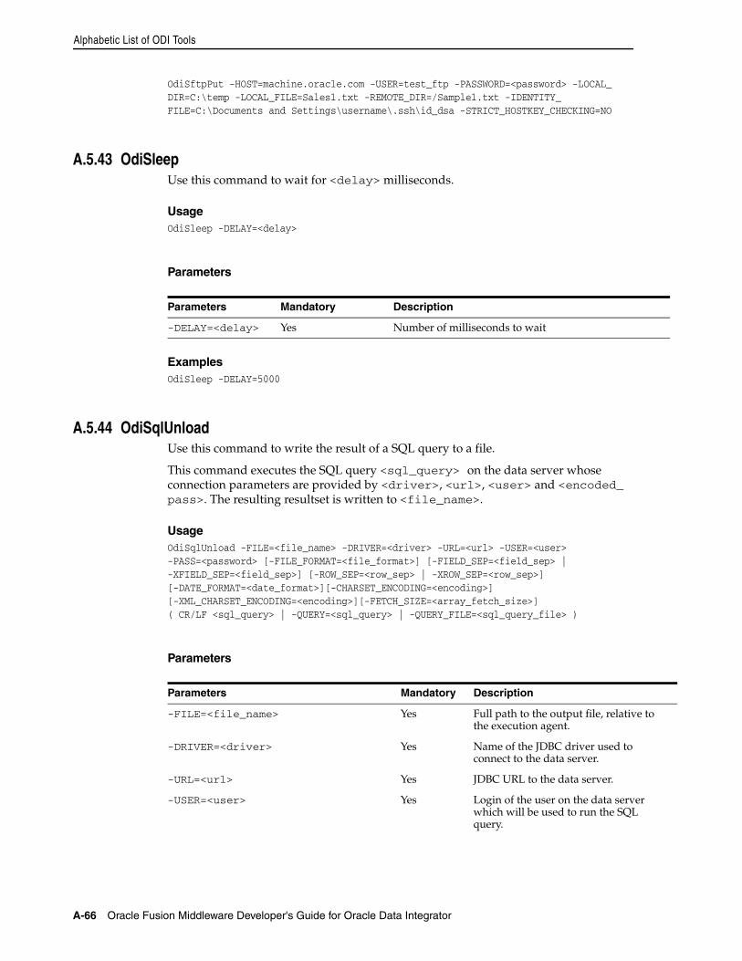
Alphabetic List of ODI Tools
A-66 Oracle Fusion Middleware Developer's Guide for Oracle Data Integrator
OdiSftpPut -HOST=machine.oracle.com -USER=test_ftp -PASSWORD=<password> -LOCAL_DIR=C:\temp -LOCAL_FILE=Sales1.txt -REMOTE_DIR=/Sample1.txt -IDENTITY_FILE=C:\Documents and Settings\username\.ssh\id_dsa -STRICT_HOSTKEY_CHECKING=NO
A.5.43 OdiSleepUse this command to wait for <delay> milliseconds.
UsageOdiSleep -DELAY=<delay>
Parameters
ExamplesOdiSleep -DELAY=5000
A.5.44 OdiSqlUnloadUse this command to write the result of a SQL query to a file.
This command executes the SQL query <sql_query> on the data server whose connection parameters are provided by <driver>, <url>, <user> and <encoded_pass>. The resulting resultset is written to <file_name>.
UsageOdiSqlUnload -FILE=<file_name> -DRIVER=<driver> -URL=<url> -USER=<user>-PASS=<password> [-FILE_FORMAT=<file_format>] [-FIELD_SEP=<field_sep> |-XFIELD_SEP=<field_sep>] [-ROW_SEP=<row_sep> | -XROW_SEP=<row_sep>][-DATE_FORMAT=<date_format>][-CHARSET_ENCODING=<encoding>][-XML_CHARSET_ENCODING=<encoding>][-FETCH_SIZE=<array_fetch_size>]( CR/LF <sql_query> | -QUERY=<sql_query> | -QUERY_FILE=<sql_query_file> )
Parameters
Parameters Mandatory Description
-DELAY=<delay> Yes Number of milliseconds to wait
Parameters Mandatory Description
-FILE=<file_name> Yes Full path to the output file, relative to the execution agent.
-DRIVER=<driver> Yes Name of the JDBC driver used to connect to the data server.
-URL=<url> Yes JDBC URL to the data server.
-USER=<user> Yes Login of the user on the data server which will be used to run the SQL query.
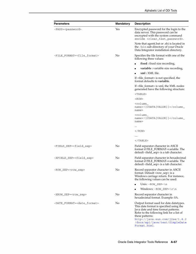
Alphabetic List of ODI Tools
Oracle Data Integrator Tools Reference A-67
-PASS=<password> Yes Encrypted password for the login to the data server. This password can be encrypted with the system command encode <clear_text_password>.
Note that agent(.bat or .sh) is located in the /bin sub-directory of your Oracle Data Integrator installation directory.
-FILE_FORMAT=<file_format> No Specifies the file format with one of the following three values:
■ fixed : fixed size recording,
■ variable : variable size recording,
■ xml : XML file.
If <file_format> is not specified, the format defaults to variable.
If <file_format> is xml, the XML nodes generated have the following structure:
<TABLE>
<ROW>
<column_name>![CDATA[VALUE]]</column_name>
<column_name>![CDATA[VALUE]]</column_name>
...
</ROW>
....
</TABLE>
-FIELD_SEP=<field_sep> No Field separator character in ASCII format if FILE_FORMAT=variable. The default <field_sep> is a tab character.
-XFIELD_SEP=<field_sep> No Field separator character in hexadecimal format if FILE_FORMAT=variable. The default <field_sep> is a tab character.
-ROW_SEP=<row_sep> No Record separator character in ASCII format. Default <row_sep> is a Windows carriage return. For instance, the following values can be used:
■ Unix: -ROW_SEP=\n
■ Windows: -ROW_SEP=\r\n
-XROW_SEP=<row_sep> No Record separator character in hexadecimal format. Example: 0A.
-DATE_FORMAT=<date_format> No Output format used for date datatypes. This date format is specified using the Java date and time format patterns. Refer to the following link for a list of these patterns: http://java.sun.com/j2se/1.4.2/docs/api/java/text/SimpleDateFormat.html.
Parameters Mandatory Description
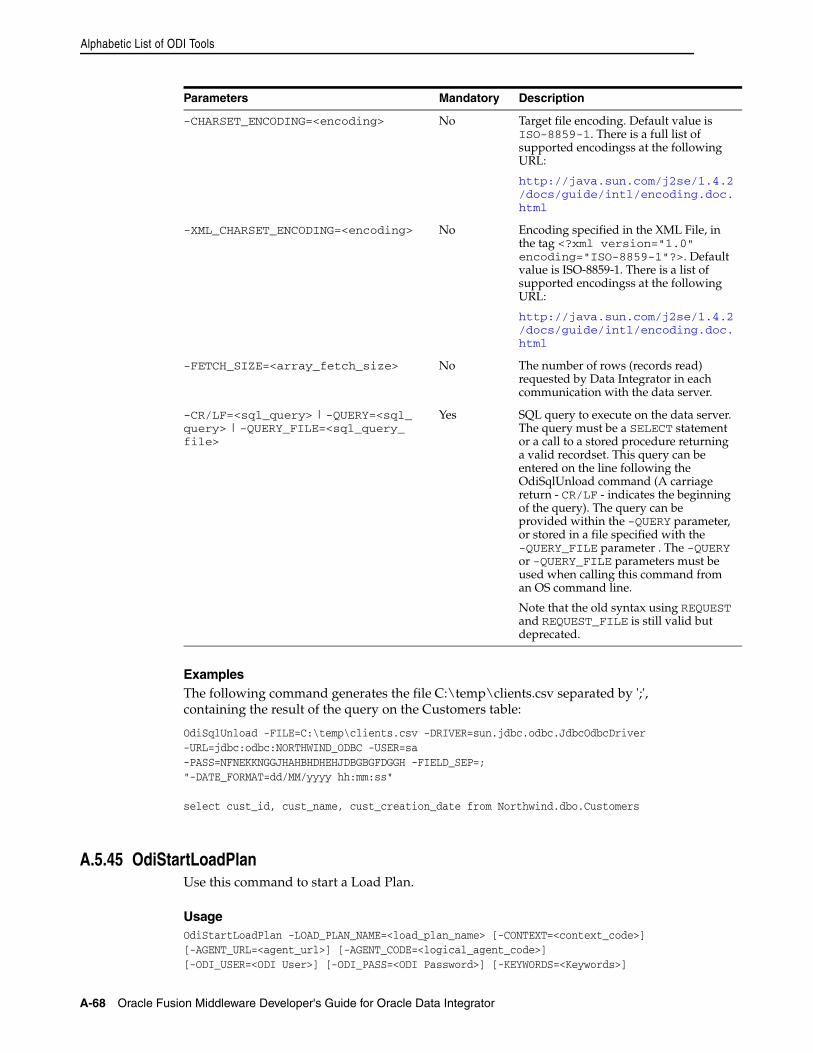
Alphabetic List of ODI Tools
A-68 Oracle Fusion Middleware Developer's Guide for Oracle Data Integrator
ExamplesThe following command generates the file C:\temp\clients.csv separated by ';', containing the result of the query on the Customers table:
OdiSqlUnload -FILE=C:\temp\clients.csv -DRIVER=sun.jdbc.odbc.JdbcOdbcDriver-URL=jdbc:odbc:NORTHWIND_ODBC -USER=sa-PASS=NFNEKKNGGJHAHBHDHEHJDBGBGFDGGH -FIELD_SEP=;"-DATE_FORMAT=dd/MM/yyyy hh:mm:ss"
select cust_id, cust_name, cust_creation_date from Northwind.dbo.Customers
A.5.45 OdiStartLoadPlanUse this command to start a Load Plan.
UsageOdiStartLoadPlan -LOAD_PLAN_NAME=<load_plan_name> [-CONTEXT=<context_code>][-AGENT_URL=<agent_url>] [-AGENT_CODE=<logical_agent_code>] [-ODI_USER=<ODI User>] [-ODI_PASS=<ODI Password>] [-KEYWORDS=<Keywords>]
-CHARSET_ENCODING=<encoding> No Target file encoding. Default value is ISO-8859-1. There is a full list of supported encodingss at the following URL:
http://java.sun.com/j2se/1.4.2/docs/guide/intl/encoding.doc.html
-XML_CHARSET_ENCODING=<encoding> No Encoding specified in the XML File, in the tag <?xml version="1.0" encoding="ISO-8859-1"?>. Default value is ISO-8859-1. There is a list of supported encodingss at the following URL:
http://java.sun.com/j2se/1.4.2/docs/guide/intl/encoding.doc.html
-FETCH_SIZE=<array_fetch_size> No The number of rows (records read) requested by Data Integrator in each communication with the data server.
-CR/LF=<sql_query> | -QUERY=<sql_query> | -QUERY_FILE=<sql_query_file>
Yes SQL query to execute on the data server. The query must be a SELECT statement or a call to a stored procedure returning a valid recordset. This query can be entered on the line following the OdiSqlUnload command (A carriage return - CR/LF - indicates the beginning of the query). The query can be provided within the -QUERY parameter, or stored in a file specified with the -QUERY_FILE parameter . The -QUERY or -QUERY_FILE parameters must be used when calling this command from an OS command line.
Note that the old syntax using REQUEST and REQUEST_FILE is still valid but deprecated.
Parameters Mandatory Description
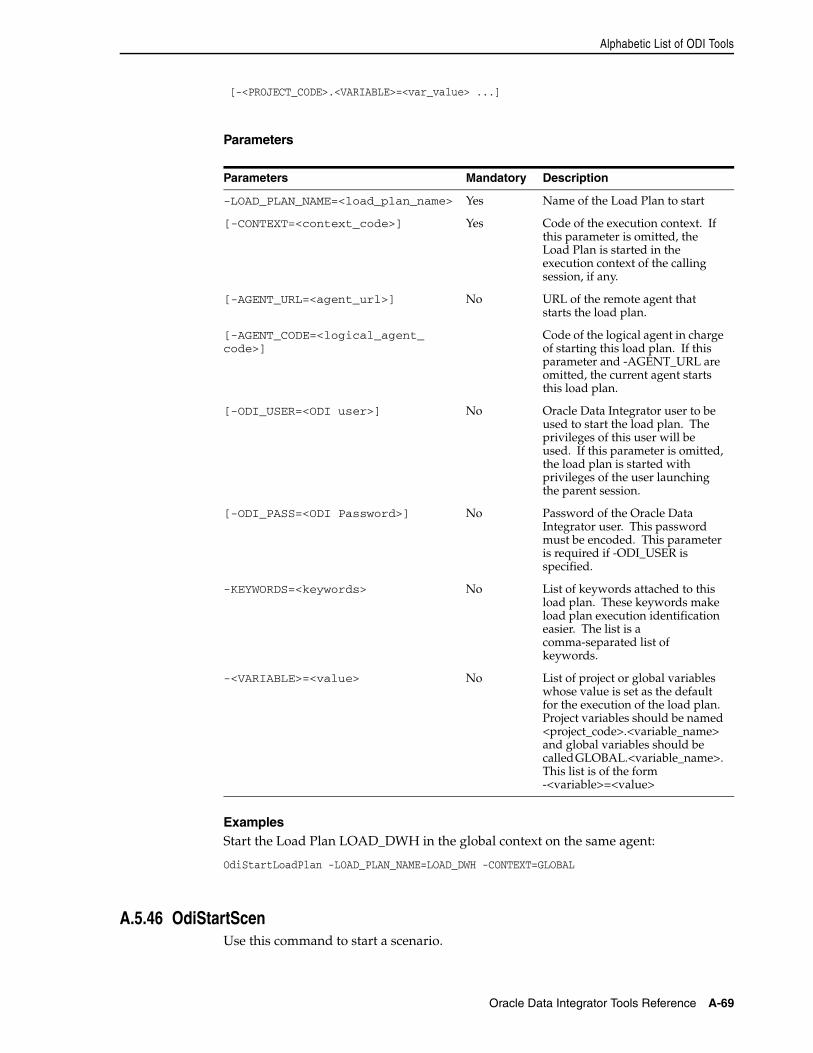
Alphabetic List of ODI Tools
Oracle Data Integrator Tools Reference A-69
[-<PROJECT_CODE>.<VARIABLE>=<var_value> ...]
Parameters
ExamplesStart the Load Plan LOAD_DWH in the global context on the same agent:
OdiStartLoadPlan -LOAD_PLAN_NAME=LOAD_DWH -CONTEXT=GLOBAL
A.5.46 OdiStartScenUse this command to start a scenario.
Parameters Mandatory Description
-LOAD_PLAN_NAME=<load_plan_name> Yes Name of the Load Plan to start
[-CONTEXT=<context_code>] Yes Code of the execution context. If this parameter is omitted, the Load Plan is started in the execution context of the calling session, if any.
[-AGENT_URL=<agent_url>] No URL of the remote agent that starts the load plan.
[-AGENT_CODE=<logical_agent_code>]
Code of the logical agent in charge of starting this load plan. If this parameter and -AGENT_URL are omitted, the current agent starts this load plan.
[-ODI_USER=<ODI user>] No Oracle Data Integrator user to be used to start the load plan. The privileges of this user will be used. If this parameter is omitted, the load plan is started with privileges of the user launching the parent session.
[-ODI_PASS=<ODI Password>] No Password of the Oracle Data Integrator user. This password must be encoded. This parameter is required if -ODI_USER is specified.
-KEYWORDS=<keywords> No List of keywords attached to this load plan. These keywords make load plan execution identification easier. The list is a comma-separated list of keywords.
-<VARIABLE>=<value> No List of project or global variables whose value is set as the default for the execution of the load plan. Project variables should be named <project_code>.<variable_name> and global variables should be called GLOBAL.<variable_name>. This list is of the form -<variable>=<value>
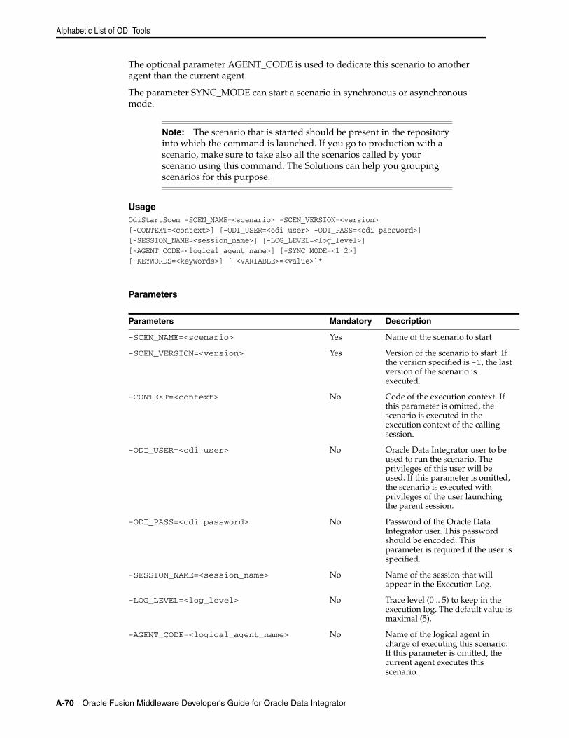
Alphabetic List of ODI Tools
A-70 Oracle Fusion Middleware Developer's Guide for Oracle Data Integrator
The optional parameter AGENT_CODE is used to dedicate this scenario to another agent than the current agent.
The parameter SYNC_MODE can start a scenario in synchronous or asynchronous mode.
UsageOdiStartScen -SCEN_NAME=<scenario> -SCEN_VERSION=<version>[-CONTEXT=<context>] [-ODI_USER=<odi user> -ODI_PASS=<odi password>][-SESSION_NAME=<session_name>] [-LOG_LEVEL=<log_level>][-AGENT_CODE=<logical_agent_name>] [-SYNC_MODE=<1|2>][-KEYWORDS=<keywords>] [-<VARIABLE>=<value>]*
Parameters
Note: The scenario that is started should be present in the repository into which the command is launched. If you go to production with a scenario, make sure to take also all the scenarios called by your scenario using this command. The Solutions can help you grouping scenarios for this purpose.
Parameters Mandatory Description
-SCEN_NAME=<scenario> Yes Name of the scenario to start
-SCEN_VERSION=<version> Yes Version of the scenario to start. If the version specified is -1, the last version of the scenario is executed.
-CONTEXT=<context> No Code of the execution context. If this parameter is omitted, the scenario is executed in the execution context of the calling session.
-ODI_USER=<odi user> No Oracle Data Integrator user to be used to run the scenario. The privileges of this user will be used. If this parameter is omitted, the scenario is executed with privileges of the user launching the parent session.
-ODI_PASS=<odi password> No Password of the Oracle Data Integrator user. This password should be encoded. This parameter is required if the user is specified.
-SESSION_NAME=<session_name> No Name of the session that will appear in the Execution Log.
-LOG_LEVEL=<log_level> No Trace level (0 .. 5) to keep in the execution log. The default value is maximal (5).
-AGENT_CODE=<logical_agent_name> No Name of the logical agent in charge of executing this scenario. If this parameter is omitted, the current agent executes this scenario.
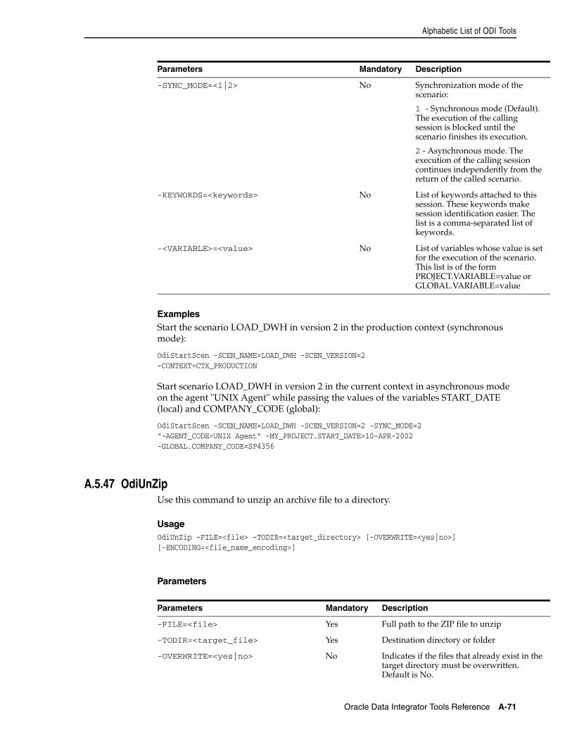
Alphabetic List of ODI Tools
Oracle Data Integrator Tools Reference A-71
ExamplesStart the scenario LOAD_DWH in version 2 in the production context (synchronous mode):
OdiStartScen -SCEN_NAME=LOAD_DWH -SCEN_VERSION=2-CONTEXT=CTX_PRODUCTION
Start scenario LOAD_DWH in version 2 in the current context in asynchronous mode on the agent "UNIX Agent" while passing the values of the variables START_DATE (local) and COMPANY_CODE (global):
OdiStartScen -SCEN_NAME=LOAD_DWH -SCEN_VERSION=2 -SYNC_MODE=2"-AGENT_CODE=UNIX Agent" -MY_PROJECT.START_DATE=10-APR-2002-GLOBAL.COMPANY_CODE=SP4356
A.5.47 OdiUnZipUse this command to unzip an archive file to a directory.
UsageOdiUnZip -FILE=<file> -TODIR=<target_directory> [-OVERWRITE=<yes|no>][-ENCODING=<file_name_encoding>]
Parameters
-SYNC_MODE=<1|2> No Synchronization mode of the scenario:
1 - Synchronous mode (Default). The execution of the calling session is blocked until the scenario finishes its execution.
2 - Asynchronous mode. The execution of the calling session continues independently from the return of the called scenario.
-KEYWORDS=<keywords> No List of keywords attached to this session. These keywords make session identification easier. The list is a comma-separated list of keywords.
-<VARIABLE>=<value> No List of variables whose value is set for the execution of the scenario. This list is of the form PROJECT.VARIABLE=value or GLOBAL.VARIABLE=value
Parameters Mandatory Description
-FILE=<file> Yes Full path to the ZIP file to unzip
-TODIR=<target_file> Yes Destination directory or folder
-OVERWRITE=<yes|no> No Indicates if the files that already exist in the target directory must be overwritten. Default is No.
Parameters Mandatory Description
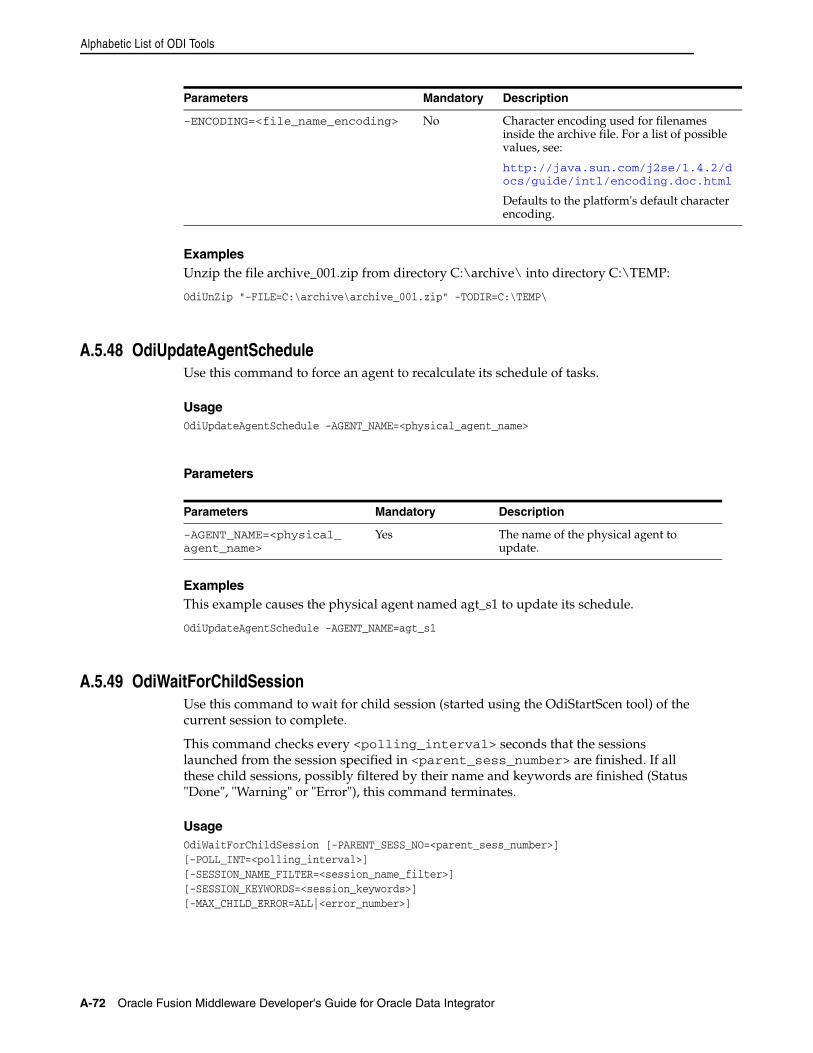
Alphabetic List of ODI Tools
A-72 Oracle Fusion Middleware Developer's Guide for Oracle Data Integrator
ExamplesUnzip the file archive_001.zip from directory C:\archive\ into directory C:\TEMP:
OdiUnZip "-FILE=C:\archive\archive_001.zip" -TODIR=C:\TEMP\
A.5.48 OdiUpdateAgentScheduleUse this command to force an agent to recalculate its schedule of tasks.
UsageOdiUpdateAgentSchedule -AGENT_NAME=<physical_agent_name>
Parameters
ExamplesThis example causes the physical agent named agt_s1 to update its schedule.
OdiUpdateAgentSchedule -AGENT_NAME=agt_s1
A.5.49 OdiWaitForChildSessionUse this command to wait for child session (started using the OdiStartScen tool) of the current session to complete.
This command checks every <polling_interval> seconds that the sessions launched from the session specified in <parent_sess_number> are finished. If all these child sessions, possibly filtered by their name and keywords are finished (Status "Done", "Warning" or "Error"), this command terminates.
UsageOdiWaitForChildSession [-PARENT_SESS_NO=<parent_sess_number>][-POLL_INT=<polling_interval>] [-SESSION_NAME_FILTER=<session_name_filter>][-SESSION_KEYWORDS=<session_keywords>][-MAX_CHILD_ERROR=ALL|<error_number>]
-ENCODING=<file_name_encoding> No Character encoding used for filenames inside the archive file. For a list of possible values, see:
http://java.sun.com/j2se/1.4.2/docs/guide/intl/encoding.doc.html
Defaults to the platform's default character encoding.
Parameters Mandatory Description
-AGENT_NAME=<physical_agent_name>
Yes The name of the physical agent to update.
Parameters Mandatory Description
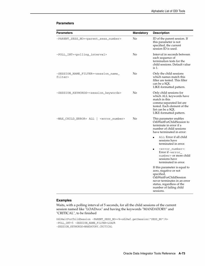
Alphabetic List of ODI Tools
Oracle Data Integrator Tools Reference A-73
Parameters
ExamplesWaits, with a polling interval of 5 seconds, for all the child sessions of the current session named like "LOADxxx" and having the keywords "MANDATORY" and "CRITICAL", to be finished
OdiWaitForChildSession -PARENT_SESS_NO=<%=odiRef.getSession("SESS_NO")%>-POLL_INT=5 -SESSION_NAME_FILTER=LOAD%-SESSION_KEYWORDS=MANDATORY,CRITICAL
Parameters Mandatory Description
-PARENT_SESS_NO=<parent_sess_number> No ID of the parent session. If this parameter is not specified, the current session ID is used.
-POLL_INT=<polling_interval> No Interval in seconds between each sequence of termination tests for the child sessions. Default value is 1.
-SESSION_NAME_FILTER=<session_name_filter>
No Only the child sessions which names match this filter are tested. This filter can be a SQL LIKE-formatted pattern.
-SESSION_KEYWORDS=<session_keywords> No Only child sessions for which ALL keywords have match in this comma-separated list are tested. Each element of the list can be a SQL LIKE-formatted pattern.
-MAX_CHILD_ERROR= ALL | <error_number> No This parameter enables OdiWaitForChildSession to terminate in error if a number of child sessions have terminated in error:
■ ALL: Error if all child sessions have terminated in error.
■ <error_number>: Error if <error_number> or more child sessions have terminated in error.
If this parameter is equal to zero, negative or not specified, OdiWaitForChildSession never terminates in an error status, regardless of the number of failing child sessions.
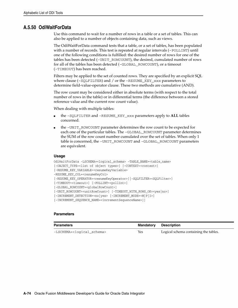
Alphabetic List of ODI Tools
A-74 Oracle Fusion Middleware Developer's Guide for Oracle Data Integrator
A.5.50 OdiWaitForDataUse this command to wait for a number of rows in a table or a set of tables. This can also be applied to a number of objects containing data, such as views.
The OdiWaitForData command tests that a table, or a set of tables, has been populated with a number of records. This test is repeated at regular intervals (-POLLINT) until one of the following conditions is fulfilled: the desired number of rows for one of the tables has been detected (-UNIT_ROWCOUNT), the desired, cumulated number of rows for all of the tables has been detected (-GLOBAL_ROWCOUNT), or a timeout (-TIMEOUT) has been reached.
Filters may be applied to the set of counted rows. They are specified by an explicit SQL where clause (-SQLFILTER) and / or the -RESUME_KEY_xxx parameters to determine field-value-operator clause. These two methods are cumulative (AND).
The row count may be considered either in absolute terms (with respect to the total number of rows in the table) or in differential terms (the difference between a stored reference value and the current row count value).
When dealing with multiple tables:
■ the -SQLFILTER and -RESUME_KEY_xxx parameters apply to ALL tables concerned.
■ the -UNIT_ROWCOUNT parameter determines the row count to be expected for each one of the particular tables. The -GLOBAL_ROWCOUNT parameter determines the SUM of the row count number cumulated over the set of tables. When only 1 table is concerned, the -UNIT_ROWCOUNT and -GLOBAL_ROWCOUNT parameters are equivalent.
UsageOdiWaitForData -LSCHEMA=<logical_schema> -TABLE_NAME=<table_name>[-OBJECT_TYPE=<list of object types>] [-CONTEXT=<context>][-RESUME_KEY_VARIABLE=<resumeKeyVariable> -RESUME_KEY_COL=<resumeKeyCol>[-RESUME_KEY_OPERATOR=<resumeKeyOperator>]|-SQLFILTER=<SQLFilter>][-TIMEOUT=<timeout>] [-POLLINT=<pollInt>] [-GLOBAL_ROWCOUNT=<globalRowCount>][-UNIT_ROWCOUNT=<unitRowCount>] [-TIMEOUT_WITH_ROWS_OK=<yes|no>][-INCREMENT_DETECTION=<no|yes> [-INCREMENT_MODE=<M|P|I>][-INCREMENT_SEQUENCE_NAME=<incrementSequenceName>]]
Parameters
Parameters Mandatory Description
-LSCHEMA=<logical_schema> Yes Logical schema containing the tables.
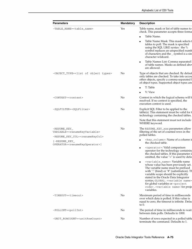
Alphabetic List of ODI Tools
Oracle Data Integrator Tools Reference A-75
-TABLE_NAME=<table_name> Yes Table name, mask or list of table names to check. This parameter accepts three format
■ Table Name.
■ Table Name Mask: This mask selects thtables to poll. The mask is specified using the SQL LIKE syntax : the % symbol replaces an unspecified numbof characters and the _ symbol is a singcharacter wildcard.
■ Table Names List: Comma separated lof table names. Masks as defined abovare allowed.
-OBJECT_TYPE=<list of object types> No Type of objects that are checked. By defaulonly tables are checked. To take into accouother objects, specify a comma-separated liof object types. Supported object types are:
■ T: Table
■ V: View
-CONTEXT=<context> No Context in which the logical schema will bresolved. If no context is specified, the execution context is used.
-SQLFILTER=<SQLFilter> No Explicit SQL Filter to be applied to the table(s). This statement must be valid for thtechnology containing the checked tables.
Note that this statement must not include tWHERE keyword.
-RESUME_KEY_VARIABLE=<resumeKeyVariable>
-RESUME_KEY_COL=<resumeKeyCol>
[-RESUME_KEY_OPERATOR=<resumeKeyOperator>]
No The RESUME_KEY_xxx parameters allow filtering of the set of counted rows in the polled tables.
■ <key_column>: Name of a column inthe checked table.
■ <operator>: Valid comparison operator for the technology containingthe checked tables. If this parameter isomitted, the value ">" is used by defau
■ <variable_name>: Variable name whose value has been previously set. The variable name must be prefixed with ":" (bind) or "#" (substitution). Thvariable scope should be explicitly stated in the Oracle Data Integrator syntax; GLOBAL.<variable name>for global variables or <project code>.<variable name> for projecvariables.
-TIMEOUT=<timeout> No Maximum period of time in milliseconds over which data is polled. If this value is equal to zero, the timeout is infinite. Defauto 0.
-POLLINT=<pollInt> No The period of time in milliseconds to wait between data polls. Defaults to 1000.
-UNIT_ROWCOUNT=<unitRowCount> No Number of rows expected in a polled tableterminate the command. Defaults to 1.
Parameters Mandatory Description
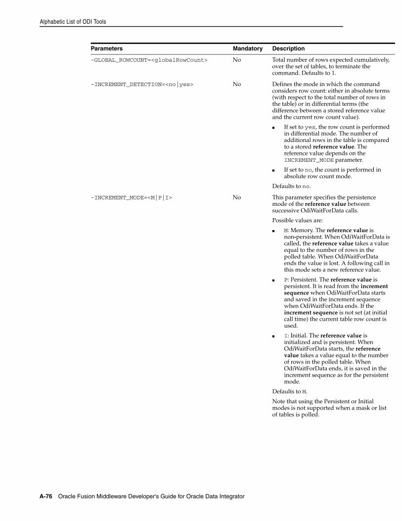
Alphabetic List of ODI Tools
A-76 Oracle Fusion Middleware Developer's Guide for Oracle Data Integrator
-GLOBAL_ROWCOUNT=<globalRowCount> No Total number of rows expected cumulatively, over the set of tables, to terminate the command. Defaults to 1.
-INCREMENT_DETECTION=<no|yes> No Defines the mode in which the command considers row count: either in absolute terms (with respect to the total number of rows in the table) or in differential terms (the difference between a stored reference value and the current row count value).
■ If set to yes, the row count is performed in differential mode. The number of additional rows in the table is compared to a stored reference value. The reference value depends on the INCREMENT_MODE parameter.
■ If set to no, the count is performed in absolute row count mode.
Defaults to no.
-INCREMENT_MODE=<M|P|I> No This parameter specifies the persistence mode of the reference value between successive OdiWaitForData calls.
Possible values are:
■ M: Memory. The reference value is non-persistent. When OdiWaitForData is called, the reference value takes a value equal to the number of rows in the polled table. When OdiWaitForData ends the value is lost. A following call in this mode sets a new reference value.
■ P: Persistent. The reference value is persistent. It is read from the increment sequence when OdiWaitForData starts and saved in the increment sequence when OdiWaitForData ends. If the increment sequence is not set (at initial call time) the current table row count is used.
■ I: Initial. The reference value is initialized and is persistent. When OdiWaitForData starts, the reference value takes a value equal to the number of rows in the polled table. When OdiWaitForData ends, it is saved in the increment sequence as for the persistent mode.
Defaults to M.
Note that using the Persistent or Initial modes is not supported when a mask or list of tables is polled.
Parameters Mandatory Description
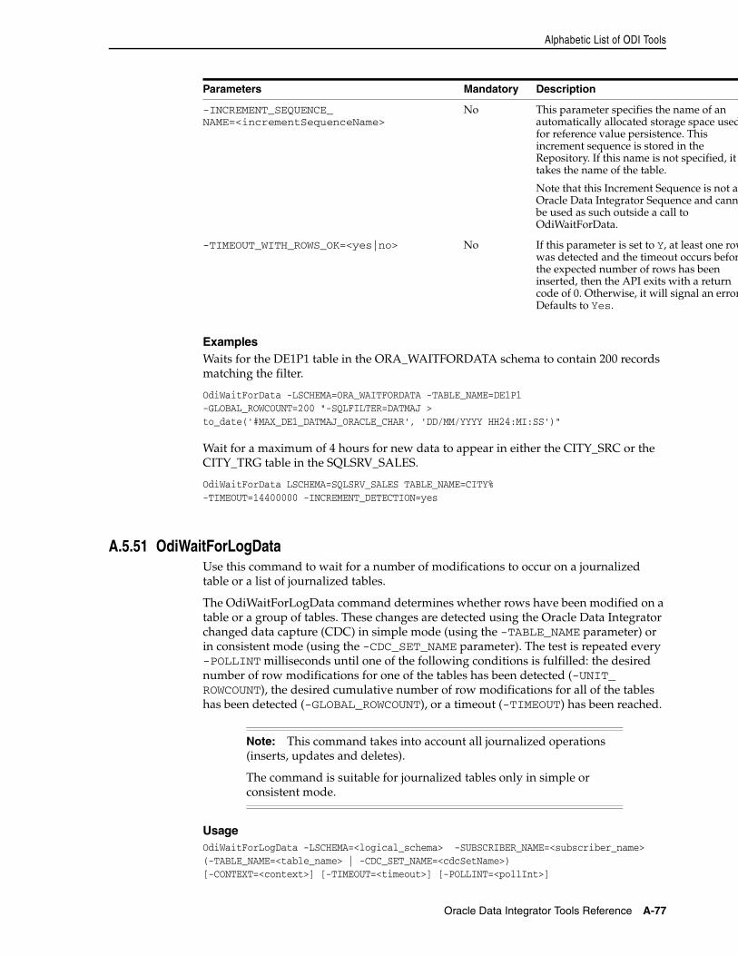
Alphabetic List of ODI Tools
Oracle Data Integrator Tools Reference A-77
ExamplesWaits for the DE1P1 table in the ORA_WAITFORDATA schema to contain 200 records matching the filter.
OdiWaitForData -LSCHEMA=ORA_WAITFORDATA -TABLE_NAME=DE1P1-GLOBAL_ROWCOUNT=200 "-SQLFILTER=DATMAJ >to_date('#MAX_DE1_DATMAJ_ORACLE_CHAR', 'DD/MM/YYYY HH24:MI:SS')"
Wait for a maximum of 4 hours for new data to appear in either the CITY_SRC or the CITY_TRG table in the SQLSRV_SALES.
OdiWaitForData LSCHEMA=SQLSRV_SALES TABLE_NAME=CITY%-TIMEOUT=14400000 -INCREMENT_DETECTION=yes
A.5.51 OdiWaitForLogDataUse this command to wait for a number of modifications to occur on a journalized table or a list of journalized tables.
The OdiWaitForLogData command determines whether rows have been modified on a table or a group of tables. These changes are detected using the Oracle Data Integrator changed data capture (CDC) in simple mode (using the -TABLE_NAME parameter) or in consistent mode (using the -CDC_SET_NAME parameter). The test is repeated every -POLLINT milliseconds until one of the following conditions is fulfilled: the desired number of row modifications for one of the tables has been detected (-UNIT_ROWCOUNT), the desired cumulative number of row modifications for all of the tables has been detected (-GLOBAL_ROWCOUNT), or a timeout (-TIMEOUT) has been reached.
UsageOdiWaitForLogData -LSCHEMA=<logical_schema> -SUBSCRIBER_NAME=<subscriber_name>(-TABLE_NAME=<table_name> | -CDC_SET_NAME=<cdcSetName>)[-CONTEXT=<context>] [-TIMEOUT=<timeout>] [-POLLINT=<pollInt>]
-INCREMENT_SEQUENCE_NAME=<incrementSequenceName>
No This parameter specifies the name of an automatically allocated storage space usedfor reference value persistence. This increment sequence is stored in the Repository. If this name is not specified, it takes the name of the table.
Note that this Increment Sequence is not anOracle Data Integrator Sequence and cannobe used as such outside a call to OdiWaitForData.
-TIMEOUT_WITH_ROWS_OK=<yes|no> No If this parameter is set to Y, at least one rowwas detected and the timeout occurs beforthe expected number of rows has been inserted, then the API exits with a return code of 0. Otherwise, it will signal an errorDefaults to Yes.
Note: This command takes into account all journalized operations (inserts, updates and deletes).
The command is suitable for journalized tables only in simple or consistent mode.
Parameters Mandatory Description
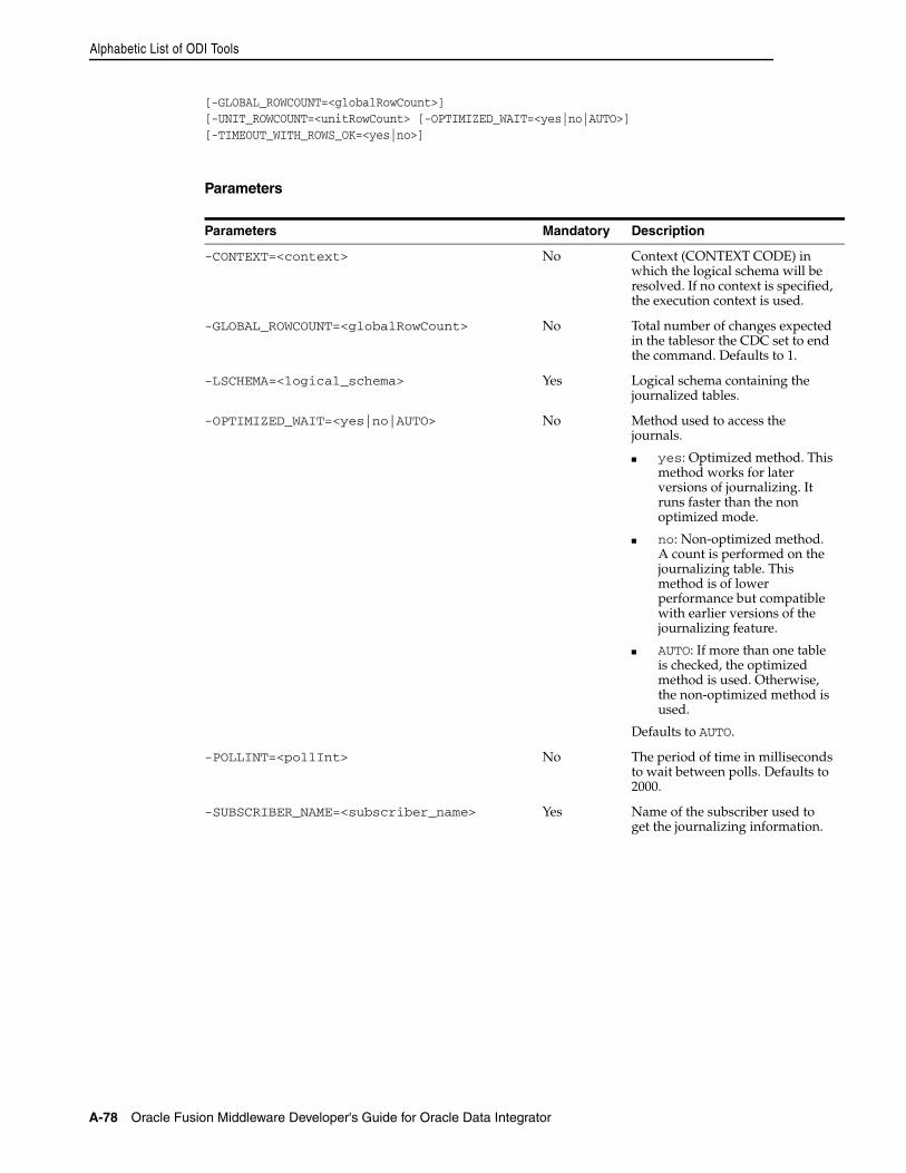
Alphabetic List of ODI Tools
A-78 Oracle Fusion Middleware Developer's Guide for Oracle Data Integrator
[-GLOBAL_ROWCOUNT=<globalRowCount>] [-UNIT_ROWCOUNT=<unitRowCount> [-OPTIMIZED_WAIT=<yes|no|AUTO>][-TIMEOUT_WITH_ROWS_OK=<yes|no>]
Parameters
Parameters Mandatory Description
-CONTEXT=<context> No Context (CONTEXT CODE) in which the logical schema will be resolved. If no context is specified, the execution context is used.
-GLOBAL_ROWCOUNT=<globalRowCount> No Total number of changes expected in the tablesor the CDC set to end the command. Defaults to 1.
-LSCHEMA=<logical_schema> Yes Logical schema containing the journalized tables.
-OPTIMIZED_WAIT=<yes|no|AUTO> No Method used to access the journals.
■ yes: Optimized method. This method works for later versions of journalizing. It runs faster than the non optimized mode.
■ no: Non-optimized method. A count is performed on the journalizing table. This method is of lower performance but compatible with earlier versions of the journalizing feature.
■ AUTO: If more than one table is checked, the optimized method is used. Otherwise, the non-optimized method is used.
Defaults to AUTO.
-POLLINT=<pollInt> No The period of time in milliseconds to wait between polls. Defaults to 2000.
-SUBSCRIBER_NAME=<subscriber_name> Yes Name of the subscriber used to get the journalizing information.
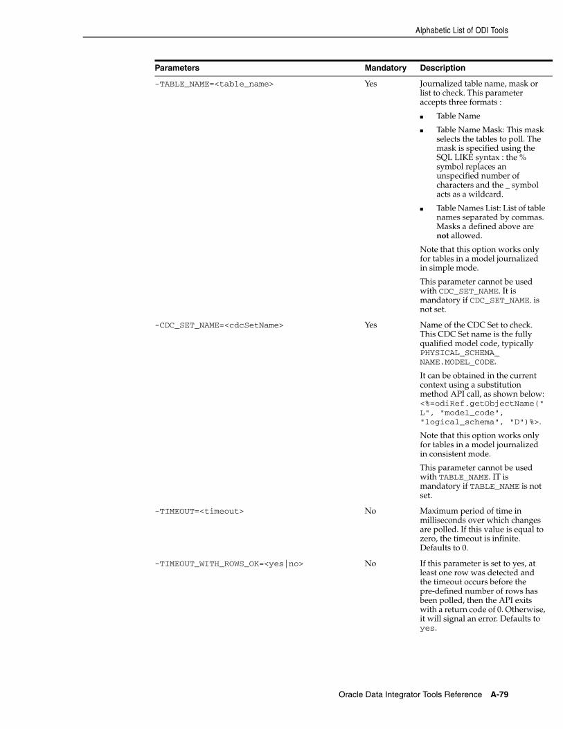
Alphabetic List of ODI Tools
Oracle Data Integrator Tools Reference A-79
-TABLE_NAME=<table_name> Yes Journalized table name, mask or list to check. This parameter accepts three formats :
■ Table Name
■ Table Name Mask: This mask selects the tables to poll. The mask is specified using the SQL LIKE syntax : the % symbol replaces an unspecified number of characters and the _ symbol acts as a wildcard.
■ Table Names List: List of table names separated by commas. Masks a defined above are not allowed.
Note that this option works only for tables in a model journalized in simple mode.
This parameter cannot be used with CDC_SET_NAME. It is mandatory if CDC_SET_NAME. is not set.
-CDC_SET_NAME=<cdcSetName> Yes Name of the CDC Set to check. This CDC Set name is the fully qualified model code, typically PHYSICAL_SCHEMA_NAME.MODEL_CODE.
It can be obtained in the current context using a substitution method API call, as shown below: <%=odiRef.getObjectName("L", "model_code", "logical_schema", "D")%>.
Note that this option works only for tables in a model journalized in consistent mode.
This parameter cannot be used with TABLE_NAME. IT is mandatory if TABLE_NAME is not set.
-TIMEOUT=<timeout> No Maximum period of time in milliseconds over which changes are polled. If this value is equal to zero, the timeout is infinite. Defaults to 0.
-TIMEOUT_WITH_ROWS_OK=<yes|no> No If this parameter is set to yes, at least one row was detected and the timeout occurs before the pre-defined number of rows has been polled, then the API exits with a return code of 0. Otherwise, it will signal an error. Defaults to yes.
Parameters Mandatory Description
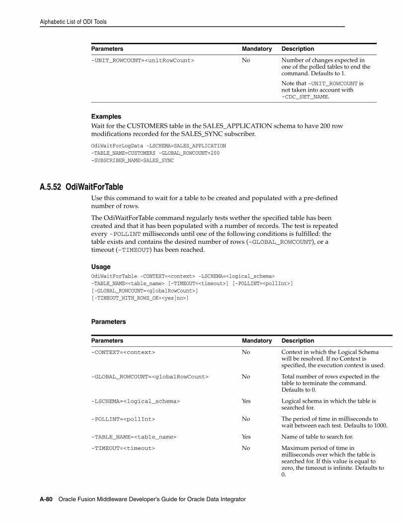
Alphabetic List of ODI Tools
A-80 Oracle Fusion Middleware Developer's Guide for Oracle Data Integrator
ExamplesWait for the CUSTOMERS table in the SALES_APPLICATION schema to have 200 row modifications recorded for the SALES_SYNC subscriber.
OdiWaitForLogData -LSCHEMA=SALES_APPLICATION-TABLE_NAME=CUSTOMERS -GLOBAL_ROWCOUNT=200-SUBSCRIBER_NAME=SALES_SYNC
A.5.52 OdiWaitForTableUse this command to wait for a table to be created and populated with a pre-defined number of rows.
The OdiWaitForTable command regularly tests wether the specified table has been created and that it has been populated with a number of records. The test is repeated every -POLLINT milliseconds until one of the following conditions is fulfilled: the table exists and contains the desired number of rows (-GLOBAL_ROWCOUNT), or a timeout (-TIMEOUT) has been reached.
UsageOdiWaitForTable -CONTEXT=<context> -LSCHEMA=<logical_schema>-TABLE_NAME=<table_name> [-TIMEOUT=<timeout>] [-POLLINT=<pollInt>][-GLOBAL_ROWCOUNT=<globalRowCount>][-TIMEOUT_WITH_ROWS_OK=<yes|no>]
Parameters
-UNIT_ROWCOUNT=<unitRowCount> No Number of changes expected in one of the polled tables to end the command. Defaults to 1.
Note that -UNIT_ROWCOUNT is not taken into account with -CDC_SET_NAME.
Parameters Mandatory Description
-CONTEXT=<context> No Context in which the Logical Schema will be resolved. If no Context is specified, the execution context is used.
-GLOBAL_ROWCOUNT=<globalRowCount> No Total number of rows expected in the table to terminate the command. Defaults to 0.
-LSCHEMA=<logical_schema> Yes Logical schema in which the table is searched for.
-POLLINT=<pollInt> No The period of time in milliseconds to wait between each test. Defaults to 1000.
-TABLE_NAME=<table_name> Yes Name of table to search for.
-TIMEOUT=<timeout> No Maximum period of time in milliseconds over which the table is searched for. If this value is equal to zero, the timeout is infinite. Defaults to 0.
Parameters Mandatory Description
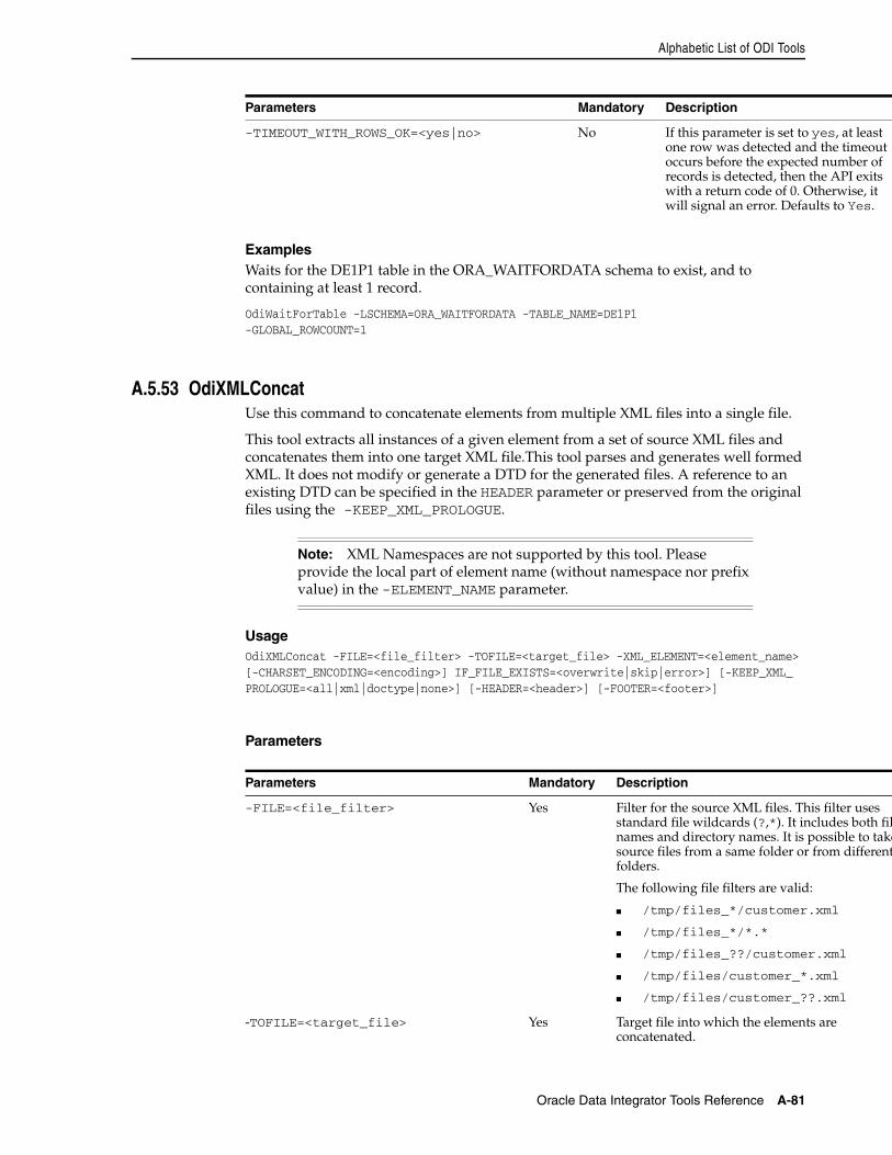
Alphabetic List of ODI Tools
Oracle Data Integrator Tools Reference A-81
ExamplesWaits for the DE1P1 table in the ORA_WAITFORDATA schema to exist, and to containing at least 1 record.
OdiWaitForTable -LSCHEMA=ORA_WAITFORDATA -TABLE_NAME=DE1P1-GLOBAL_ROWCOUNT=1
A.5.53 OdiXMLConcatUse this command to concatenate elements from multiple XML files into a single file.
This tool extracts all instances of a given element from a set of source XML files and concatenates them into one target XML file.This tool parses and generates well formed XML. It does not modify or generate a DTD for the generated files. A reference to an existing DTD can be specified in the HEADER parameter or preserved from the original files using the -KEEP_XML_PROLOGUE.
UsageOdiXMLConcat -FILE=<file_filter> -TOFILE=<target_file> -XML_ELEMENT=<element_name> [-CHARSET_ENCODING=<encoding>] IF_FILE_EXISTS=<overwrite|skip|error>] [-KEEP_XML_PROLOGUE=<all|xml|doctype|none>] [-HEADER=<header>] [-FOOTER=<footer>]
Parameters
-TIMEOUT_WITH_ROWS_OK=<yes|no> No If this parameter is set to yes, at least one row was detected and the timeout occurs before the expected number of records is detected, then the API exits with a return code of 0. Otherwise, it will signal an error. Defaults to Yes.
Note: XML Namespaces are not supported by this tool. Please provide the local part of element name (without namespace nor prefix value) in the -ELEMENT_NAME parameter.
Parameters Mandatory Description
-FILE=<file_filter> Yes Filter for the source XML files. This filter uses standard file wildcards (?,*). It includes both filnames and directory names. It is possible to takesource files from a same folder or from differentfolders.
The following file filters are valid:
■ /tmp/files_*/customer.xml
■ /tmp/files_*/*.*
■ /tmp/files_??/customer.xml
■ /tmp/files/customer_*.xml
■ /tmp/files/customer_??.xml
-TOFILE=<target_file> Yes Target file into which the elements are concatenated.
Parameters Mandatory Description
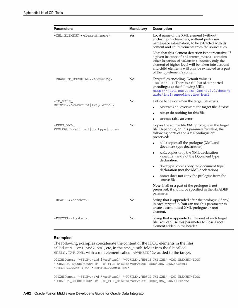
Alphabetic List of ODI Tools
A-82 Oracle Fusion Middleware Developer's Guide for Oracle Data Integrator
ExamplesThe following examples concatenate the content of the IDOC elements in the files called ord1.xml, ord2.xml, etc, in the ord_i sub-folder into the file called MDSLS.TXT.XML, with a root element called <WMMBID02> added to the target.
OdiXMLConcat "-FILE=./ord_i/ord*.xml" "-TOFILE=./MDSLS.TXT.XML" -XML_ELEMENT=IDOC "-CHARSET_ENCODING=UTF-8" -IF_FILE_EXISTS=overwrite -KEEP_XML_PROLOGUE=xml "-HEADER=<WMMBID02>" "-FOOTER=</WMMBID02>"
OdiXMLConcat "-FILE=./o?d_*/ord*.xml" "-TOFILE=./MDSLS.TXT.XML" -XML_ELEMENT=IDOC "-CHARSET_ENCODING=UTF-8" -IF_FILE_EXISTS=overwrite -KEEP_XML_PROLOGUE=none
-XML_ELEMENT=<element_name> Yes Local name of the XML element (without enclosing <> characters, without prefix nor namespace information) to be extracted with its content and child elements from the source files.
Note that this element detection is not recursive. If a given instance of <element_name> contains other instances of <element_name>, only the element of higher level will be taken into account and child elements will only be extracted as a part of the top element’s content.
-CHARSET_ENCODING=<encoding> No Target files encoding. Default value is ISO-8859-1. There is a full list of supported encodingss at the following URL: http://java.sun.com/j2se/1.4.2/docs/guide/intl/encoding.doc.html
-IF_FILE_EXISTS=<overwrite|skip|error>
No Define behavior when the target file exists.
■ overwrite: overwrite the target file if exists
■ skip: do nothing for this file
■ error: raise an error
-KEEP_XML_PROLOGUE=<all|xml|doctype|none>
No Copies the source file XML prologue in the target file. Depending on this parameter’s value, the following parts of the XML prologue are preserved:
■ all: copies all the prologue (XML and document type declaration)
■ xml: copies only the XML declaration <?xml...?> and not the Document type declaration.
■ doctype: copies only the document type declaration (not the XML declaration)
■ none: does not copy the prologue from the source file.
Note: If all or a part of the prologue is not preserved, it should be specified in the HEADER parameter.
-HEADER=<header> No String that is appended after the prologue (if any) in each target file. You can use this parameter to create a customized XML prologue or root element.
-FOOTER=<footer> No String that is appended at the end of each target file. You can use this parameter to close a root element added in the header.
Parameters Mandatory Description
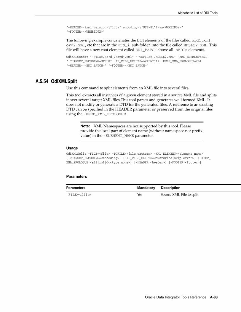
Alphabetic List of ODI Tools
Oracle Data Integrator Tools Reference A-83
"-HEADER=<?xml version=\"1.0\" encoding=\"UTF-8\"?>\n<WMMBID02>" "-FOOTER=</WMMBID02>"
The following example concatenates the EDI elements of the files called ord1.xml, ord2.xml, etc that are in the ord_i sub-folder, into the file called MDSLS2.XML. This file will have a new root element called EDI_BATCH above all <EDI> elements.
OdiXMLConcat "-FILE=./o?d_?/ord*.xml" "-TOFILE=./MDSLS2.XML" -XML_ELEMENT=EDI "-CHARSET_ENCODING=UTF-8" -IF_FILE_EXISTS=overwrite -KEEP_XML_PROLOGUE=xml "-HEADER= <EDI_BATCH>" "-FOOTER=</EDI_BATCH>"
A.5.54 OdiXMLSplitUse this command to split elements from an XML file into several files.
This tool extracts all instances of a given element stored in a source XML file and splits it over several target XML files.This tool parses and generates well formed XML. It does not modify or generate a DTD for the generated files. A reference to an existing DTD can be specified in the HEADER parameter or preserved from the original files using the -KEEP_XML_PROLOGUE.
UsageOdiXMLSplit -FILE=<file> -TOFILE=<file_pattern> -XML_ELEMENT=<element_name> [-CHARSET_ENCODING=<encoding>] [-IF_FILE_EXISTS=<overwrite|skip|error>] [-KEEP_XML_PROLOGUE=<all|xml|doctype|none>] [-HEADER=<header>] [-FOOTER=<footer>]
Parameters
Note: XML Namespaces are not supported by this tool. Please provide the local part of element name (without namespace nor prefix value) in the -ELEMENT_NAME parameter.
Parameters Mandatory Description
-FILE=<file> Yes Source XML File to split
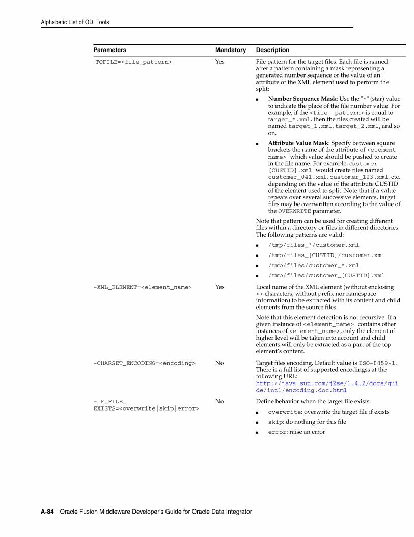
Alphabetic List of ODI Tools
A-84 Oracle Fusion Middleware Developer's Guide for Oracle Data Integrator
-TOFILE=<file_pattern> Yes File pattern for the target files. Each file is named after a pattern containing a mask representing a generated number sequence or the value of an attribute of the XML element used to perform the split:
■ Number Sequence Mask: Use the "*" (star) value to indicate the place of the file number value. For example, if the <file_ pattern> is equal to target_*.xml, then the files created will be named target_1.xml, target_2.xml, and so on.
■ Attribute Value Mask: Specify between square brackets the name of the attribute of <element_name> which value should be pushed to create in the file name. For example, customer_[CUSTID].xml would create files named customer_041.xml, customer_123.xml, etc. depending on the value of the attribute CUSTID of the element used to split. Note that if a value repeats over several successive elements, target files may be overwritten according to the value of the OVERWRITE parameter.
Note that pattern can be used for creating different files within a directory or files in different directories. The following patterns are valid:
■ /tmp/files_*/customer.xml
■ /tmp/files_[CUSTID]/customer.xml
■ /tmp/files/customer_*.xml
■ /tmp/files/customer_[CUSTID].xml
-XML_ELEMENT=<element_name> Yes Local name of the XML element (without enclosing <> characters, without prefix nor namespace information) to be extracted with its content and child elements from the source files.
Note that this element detection is not recursive. If a given instance of <element_name> contains other instances of <element_name>, only the element of higher level will be taken into account and child elements will only be extracted as a part of the top element’s content.
-CHARSET_ENCODING=<encoding> No Target files encoding. Default value is ISO-8859-1. There is a full list of supported encodingss at the following URL: http://java.sun.com/j2se/1.4.2/docs/guide/intl/encoding.doc.html
-IF_FILE_EXISTS=<overwrite|skip|error>
No Define behavior when the target file exists.
■ overwrite: overwrite the target file if exists
■ skip: do nothing for this file
■ error: raise an error
Parameters Mandatory Description
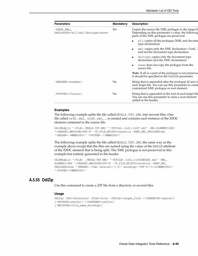
Alphabetic List of ODI Tools
Oracle Data Integrator Tools Reference A-85
ExamplesThe following example splits the file called MDSLS.TXT.XML into several files. One file called ord1.xml, ord2.xml, ... is created and contains each instance of the IDOC element contained in the source file.
OdiXMLSplit "-FILE=./MDSLS.TXT.XML" "-TOFILE=./ord_i/ord*.xml" -XML_ELEMENT=IDOC "-CHARSET_ENCODING=UTF-8" -IF_FILE_EXISTS=overwrite -KEEP_XML_PROLOGUE=xml "-HEADER= <WMMBID02>" "-FOOTER= </WMMBID02>"
The following example splits the file called MDSLS.TXT.XML the same way as the example above except that the files are named using the value of the BEGIN attribute of the IDOC element that is being split. The XML prologue is not preserved in this example but entirely generated in the header.
OdiXMLSplit "-FILE= ./MDSLS.TXT.XML" "-TOFILE=./ord_i/ord[BEGIN].xml" -XML_ELEMENT=IDOC "-CHARSET_ENCODING=UTF-8" -IF_FILE_EXISTS=overwrite -KEEP_XML_PROLOGUE=none "-HEADER= <?xml version=\"1.0\" encoding=\"UTF-8\"?>\n<WMMBID02>" "-FOOTER=</WMMBID02>"
A.5.55 OdiZipUse this command to create a ZIP file from a directory or several files.
UsageOdiZip -DIR=<directory> -FILE=<file> -TOFILE=<target_file> [-OVERWRITE=<yes|no>][-RECURSE=<yes|no>] [-CASESENS=<yes|no>][-ENCODING=<file_name_encoding>]
-KEEP_XML_PROLOGUE=<all|xml|doctype|none>
No Copies the source file XML prologue in the target filDepending on this parameter’s value, the followingparts of the XML prologue are preserved:
■ all: copies all the prologue (XML and documetype declaration)
■ xml: copies only the XML declaration <?xml...?and not the Document type declaration.
■ doctype: copies only the document type declaration (not the XML declaration)
■ none: does not copy the prologue from the source file.
Note: If all or a part of the prologue is not preservedit should be specified in the HEADER parameter.
-HEADER=<header> No String that is appended after the prologue (if any) ineach target file. You can use this parameter to createcustomized XML prologue or root element.
-FOOTER=<footer> No String that is appended at the end of each target fileYou can use this parameter to close a root element added in the header.
Parameters Mandatory Description
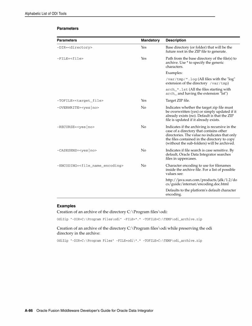
Alphabetic List of ODI Tools
A-86 Oracle Fusion Middleware Developer's Guide for Oracle Data Integrator
Parameters
ExamplesCreation of an archive of the directory C:\Program files\odi:
OdiZip "-DIR=C:\Program Files\odi" -FILE=*.* -TOFILE=C:\TEMP\odi_archive.zip
Creation of an archive of the directory C:\Program files\odi while preserving the odi directory in the archive:
OdiZip "-DIR=C:\Program Files" -FILE=odi\*.* -TOFILE=C:\TEMP\odi_archive.zip
Parameters Mandatory Description
-DIR=<directory> Yes Base directory (or folder) that will be the future root in the ZIP file to generate.
-FILE=<file> Yes Path from the base directory of the file(s) to archive. Use * to specify the generic characters.
Examples:
/var/tmp/*.log (All files with the "log" extension of the directory /var/tmp)
arch_*.lst (All the files starting with arch_ and having the extension "lst")
-TOFILE=<target_file> Yes Target ZIP file.
-OVERWRITE=<yes|no> No Indicates whether the target zip file must be overwritten (yes) or simply updated if it already exists (no). Default is that the ZIP file is updated if it already exists.
-RECURSE=<yes|no> No Indicates if the archiving is recursive in the case of a directory that contains other directories. The value no indicates that only the files contained in the directory to copy (without the sub-folders) will be archived.
-CASESENS=<yes|no> No Indicates if file search is case sensitive. By default, Oracle Data Integrator searches files in uppercases.
-ENCODING=<file_name_encoding> No Character encoding to use for filenames inside the archive file. For a list of possible values see:
http://java.sun.com/products/jdk/1.2/docs/guide/internat/encoding.doc.html
Defaults to the platform's default character encoding.
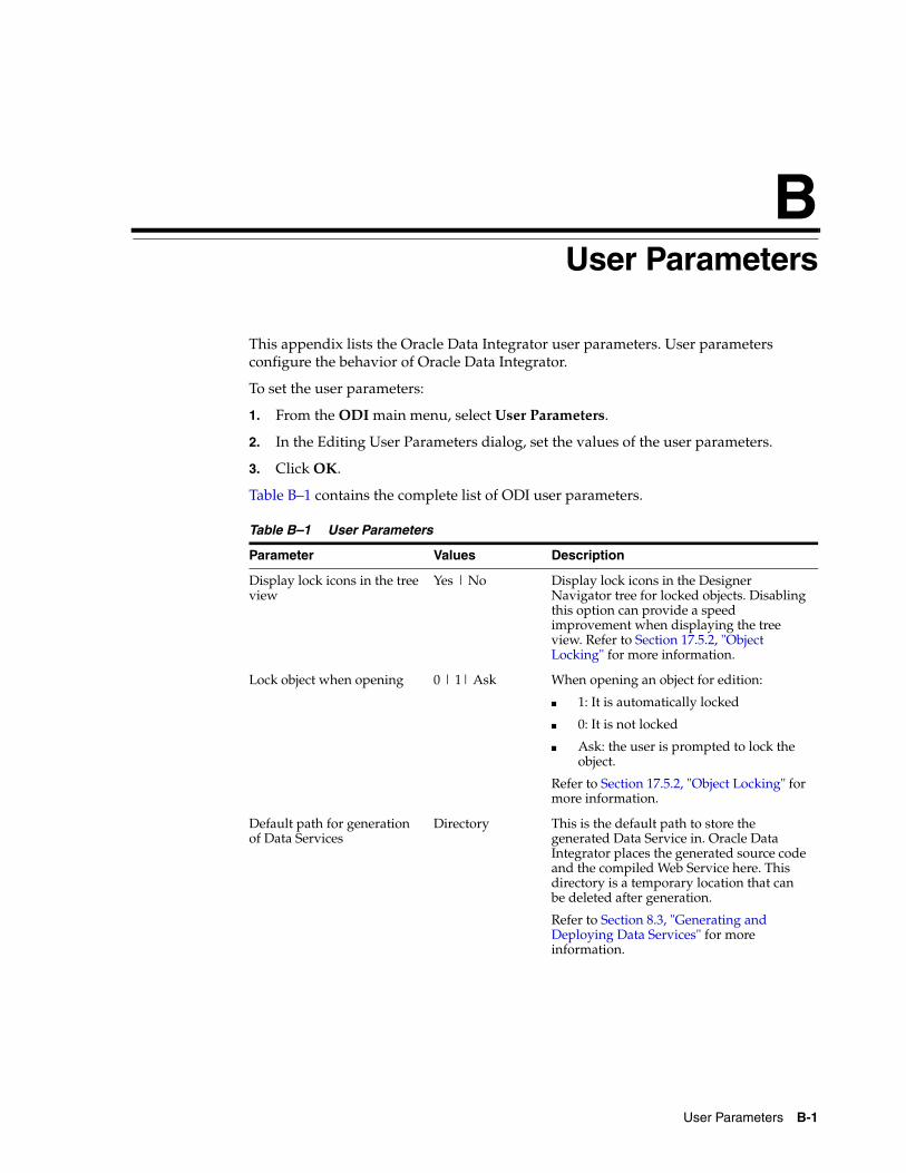
B
User Parameters B-1
BUser Parameters
This appendix lists the Oracle Data Integrator user parameters. User parameters configure the behavior of Oracle Data Integrator.
To set the user parameters:
1. From the ODI main menu, select User Parameters.
2. In the Editing User Parameters dialog, set the values of the user parameters.
3. Click OK.
Table B–1 contains the complete list of ODI user parameters.
Table B–1 User Parameters
Parameter Values Description
Display lock icons in the tree view
Yes | No Display lock icons in the Designer Navigator tree for locked objects. Disabling this option can provide a speed improvement when displaying the tree view. Refer to Section 17.5.2, "Object Locking" for more information.
Lock object when opening 0 | 1| Ask When opening an object for edition:
■ 1: It is automatically locked
■ 0: It is not locked
■ Ask: the user is prompted to lock the object.
Refer to Section 17.5.2, "Object Locking" for more information.
Default path for generation of Data Services
Directory This is the default path to store the generated Data Service in. Oracle Data Integrator places the generated source code and the compiled Web Service here. This directory is a temporary location that can be deleted after generation.
Refer to Section 8.3, "Generating and Deploying Data Services" for more information.
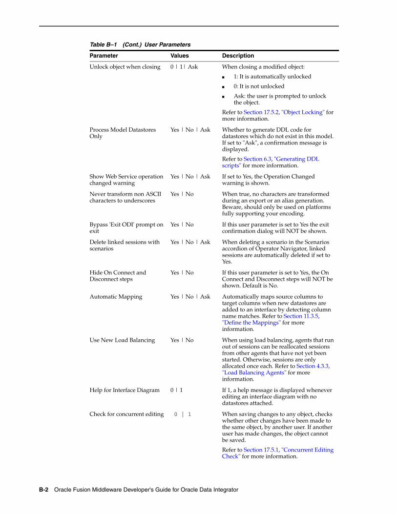
B-2 Oracle Fusion Middleware Developer's Guide for Oracle Data Integrator
Unlock object when closing 0 | 1| Ask When closing a modified object:
■ 1: It is automatically unlocked
■ 0: It is not unlocked
■ Ask: the user is prompted to unlock the object.
Refer to Section 17.5.2, "Object Locking" for more information.
Process Model Datastores Only
Yes | No | Ask Whether to generate DDL code for datastores which do not exist in this model. If set to "Ask", a confirmation message is displayed.
Refer to Section 6.3, "Generating DDL scripts" for more information.
Show Web Service operation changed warning
Yes | No | Ask If set to Yes, the Operation Changed warning is shown.
Never transform non ASCII characters to underscores
Yes | No When true, no characters are transformed during an export or an alias generation. Beware, should only be used on platforms fully supporting your encoding.
Bypass 'Exit ODI' prompt on exit
Yes | No If this user parameter is set to Yes the exit confirmation dialog will NOT be shown.
Delete linked sessions with scenarios
Yes | No | Ask When deleting a scenario in the Scenarios accordion of Operator Navigator, linked sessions are automatically deleted if set to Yes.
Hide On Connect and Disconnect steps
Yes | No If this user parameter is set to Yes, the On Connect and Disconnect steps will NOT be shown. Default is No.
Automatic Mapping Yes | No | Ask Automatically maps source columns to target columns when new datastores are added to an interface by detecting column name matches. Refer to Section 11.3.5, "Define the Mappings" for more information.
Use New Load Balancing Yes | No When using load balancing, agents that run out of sessions can be reallocated sessions from other agents that have not yet been started. Otherwise, sessions are only allocated once each. Refer to Section 4.3.3, "Load Balancing Agents" for more information.
Help for Interface Diagram 0 | 1 If 1, a help message is displayed whenever editing an interface diagram with no datastores attached.
Check for concurrent editing 0 | 1 When saving changes to any object, checks whether other changes have been made to the same object, by another user. If another user has made changes, the object cannot be saved.
Refer to Section 17.5.1, "Concurrent Editing Check" for more information.
Table B–1 (Cont.) User Parameters
Parameter Values Description
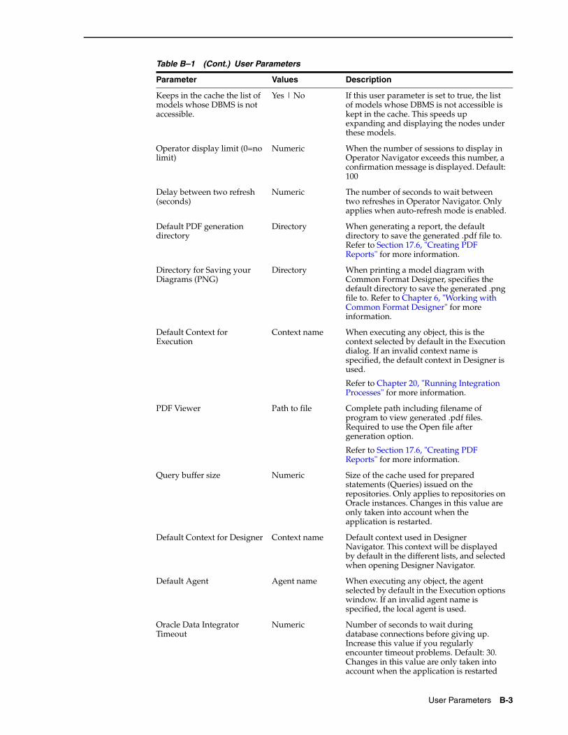
User Parameters B-3
Keeps in the cache the list of models whose DBMS is not accessible.
Yes | No If this user parameter is set to true, the list of models whose DBMS is not accessible is kept in the cache. This speeds up expanding and displaying the nodes under these models.
Operator display limit (0=no limit)
Numeric When the number of sessions to display in Operator Navigator exceeds this number, a confirmation message is displayed. Default: 100
Delay between two refresh (seconds)
Numeric The number of seconds to wait between two refreshes in Operator Navigator. Only applies when auto-refresh mode is enabled.
Default PDF generation directory
Directory When generating a report, the default directory to save the generated .pdf file to. Refer to Section 17.6, "Creating PDF Reports" for more information.
Directory for Saving your Diagrams (PNG)
Directory When printing a model diagram with Common Format Designer, specifies the default directory to save the generated .png file to. Refer to Chapter 6, "Working with Common Format Designer" for more information.
Default Context for Execution
Context name When executing any object, this is the context selected by default in the Execution dialog. If an invalid context name is specified, the default context in Designer is used.
Refer to Chapter 20, "Running Integration Processes" for more information.
PDF Viewer Path to file Complete path including filename of program to view generated .pdf files. Required to use the Open file after generation option.
Refer to Section 17.6, "Creating PDF Reports" for more information.
Query buffer size Numeric Size of the cache used for prepared statements (Queries) issued on the repositories. Only applies to repositories on Oracle instances. Changes in this value are only taken into account when the application is restarted.
Default Context for Designer Context name Default context used in Designer Navigator. This context will be displayed by default in the different lists, and selected when opening Designer Navigator.
Default Agent Agent name When executing any object, the agent selected by default in the Execution options window. If an invalid agent name is specified, the local agent is used.
Oracle Data Integrator Timeout
Numeric Number of seconds to wait during database connections before giving up. Increase this value if you regularly encounter timeout problems. Default: 30. Changes in this value are only taken into account when the application is restarted
Table B–1 (Cont.) User Parameters
Parameter Values Description
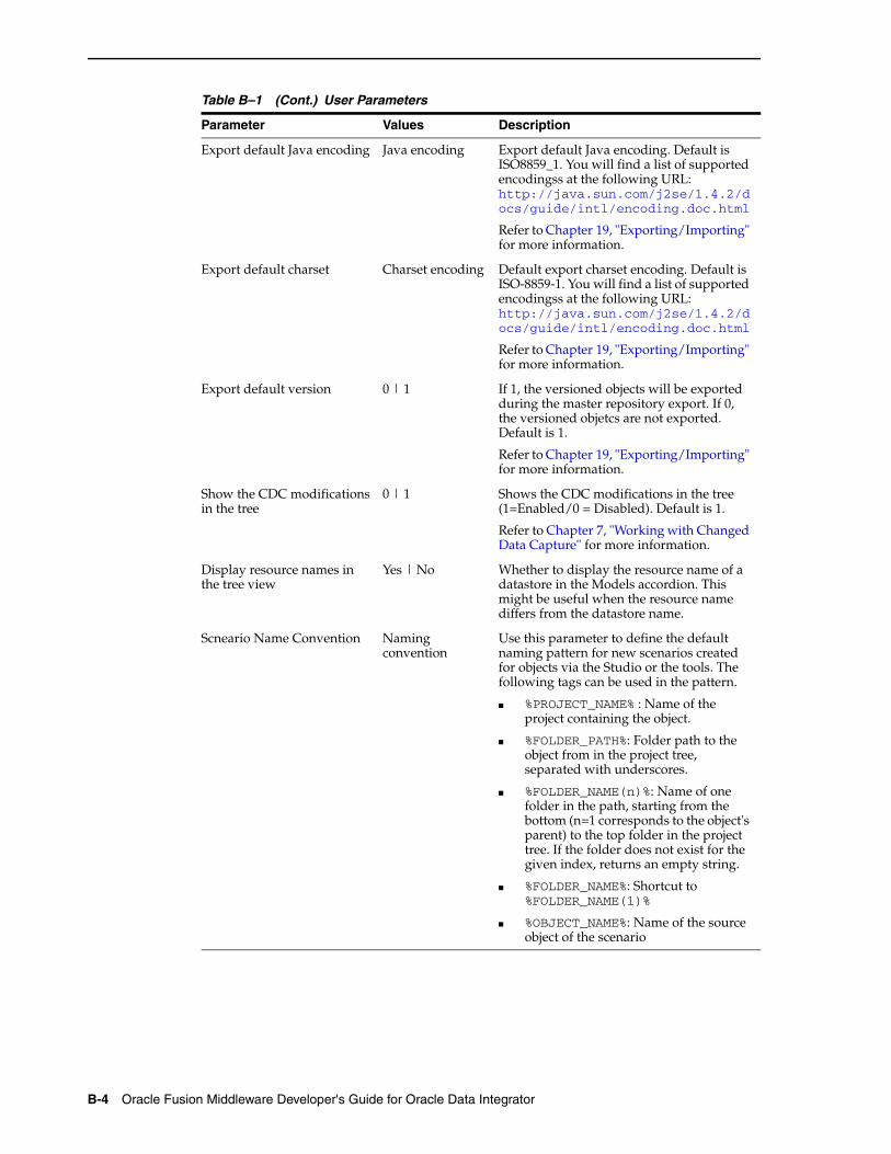
B-4 Oracle Fusion Middleware Developer's Guide for Oracle Data Integrator
Export default Java encoding Java encoding Export default Java encoding. Default is ISO8859_1. You will find a list of supported encodingss at the following URL: http://java.sun.com/j2se/1.4.2/docs/guide/intl/encoding.doc.html
Refer to Chapter 19, "Exporting/Importing" for more information.
Export default charset Charset encoding Default export charset encoding. Default is ISO-8859-1. You will find a list of supported encodingss at the following URL: http://java.sun.com/j2se/1.4.2/docs/guide/intl/encoding.doc.html
Refer to Chapter 19, "Exporting/Importing" for more information.
Export default version 0 | 1 If 1, the versioned objects will be exported during the master repository export. If 0, the versioned objetcs are not exported. Default is 1.
Refer to Chapter 19, "Exporting/Importing" for more information.
Show the CDC modifications in the tree
0 | 1 Shows the CDC modifications in the tree (1=Enabled/0 = Disabled). Default is 1.
Refer to Chapter 7, "Working with Changed Data Capture" for more information.
Display resource names in the tree view
Yes | No Whether to display the resource name of a datastore in the Models accordion. This might be useful when the resource name differs from the datastore name.
Scneario Name Convention Naming convention
Use this parameter to define the default naming pattern for new scenarios created for objects via the Studio or the tools. The following tags can be used in the pattern.
■ %PROJECT_NAME% : Name of the project containing the object.
■ %FOLDER_PATH%: Folder path to the object from in the project tree, separated with underscores.
■ %FOLDER_NAME(n)%: Name of one folder in the path, starting from the bottom (n=1 corresponds to the object's parent) to the top folder in the project tree. If the folder does not exist for the given index, returns an empty string.
■ %FOLDER_NAME%: Shortcut to %FOLDER_NAME(1)%
■ %OBJECT_NAME%: Name of the source object of the scenario
Table B–1 (Cont.) User Parameters
Parameter Values Description

User Parameters B-5

B-6 Oracle Fusion Middleware Developer's Guide for Oracle Data Integrator