oak lawn coach-house style garage, workshop … lawn coach-house style garage, workshop and car barn...
TRANSCRIPT

More than eighteen different garages, vehicle barns and workshops can be built with the help ofthis set of plans. The 24’ deep Main Building can be built at 24’, 26’ or 28’ wide. It can have full
stairs to the storage Loft or inexpensive pull-down stairs. Expansion Sheds can be added toeither side for more parking, storage or workshop space. Vehicle doors can be hinged or overhead
garage doors in a variety of sizes. A loft door and lift post are optional. See the Sample Layoutsfor just a few of the possible designs.
Oak Lawn Coach-House StyleOak Lawn Coach-House StyleOak Lawn Coach-House StyleOak Lawn Coach-House StyleOak Lawn Coach-House StyleGarage, Workshop and Car Barn PlansGarage, Workshop and Car Barn PlansGarage, Workshop and Car Barn PlansGarage, Workshop and Car Barn PlansGarage, Workshop and Car Barn Plans
www.TodaysPlans.com Design Set #OC-2424D
Copyright 2008 - TodaysPlans.comThese plans are protected by U.S. and International copyright law. They may be used once, to help build one building.
Any other use, copying or dissemination is strictly prohibited.

Terms of Use, Notes and BuildingTerms of Use, Notes and BuildingTerms of Use, Notes and BuildingTerms of Use, Notes and BuildingTerms of Use, Notes and BuildingResourcesResourcesResourcesResourcesResourcesN1 and N2
Sample LayoutsSample LayoutsSample LayoutsSample LayoutsSample Layouts1 - Two Car Garage
2 - Three Bay Vehicle Barn3 - Four Car Coach House Style Garage
4 - Three Bay CarBarn & Workshop
Oak Lawn Coach-House Garage, Barn and Workshop Plans Oak Lawn Coach-House Garage, Barn and Workshop Plans Oak Lawn Coach-House Garage, Barn and Workshop Plans Oak Lawn Coach-House Garage, Barn and Workshop Plans Oak Lawn Coach-House Garage, Barn and Workshop Plans INDEX INDEX INDEX INDEX INDEX
Material ListsMaterial ListsMaterial ListsMaterial ListsMaterial ListsBuilding Material Lists for all size Main Buildings and Expansion Sheds can be found online at:
www.TodaysPans.comwww.TodaysPans.comwww.TodaysPans.comwww.TodaysPans.comwww.TodaysPans.com
Main Building PlansMain Building PlansMain Building PlansMain Building PlansMain Building PlansP1 - Floor Plan
P2- Floor Plan NotesP3 - Optional Floor Plan
P4 - Loft Framing PlanP5- Roof Framing Plan
P6 - Loft and Roof Framing Plan Notes
Main Building ElevationsMain Building ElevationsMain Building ElevationsMain Building ElevationsMain Building ElevationsE1 - Front Elevation
E2 - Elevation NotesE3 - Front Elevation Options
E4 - Rear ElevationE5 - Side ElevationE6 - Side Elevation
Main Building SectionsMain Building SectionsMain Building SectionsMain Building SectionsMain Building SectionsS1 - Framing Section
S2 - Framing Section NotesS3 - Wall Sections
Main Building DetailsMain Building DetailsMain Building DetailsMain Building DetailsMain Building DetailsD1 - Post Connections
D2 - Walk Door & Window FramingD3 - 7’ High Vehicle Door Door FramingD4 - 8’ High Vehicle Door Door Framing
Main Building & Expansion ShedMain Building & Expansion ShedMain Building & Expansion ShedMain Building & Expansion ShedMain Building & Expansion ShedFoundation DetailsFoundation DetailsFoundation DetailsFoundation DetailsFoundation Details
FD1 - Frost Wall FootingFD2 - Monolithic Slab Foundation
FD3 - Thickened Slab
Expansion ShedExpansion ShedExpansion ShedExpansion ShedExpansion ShedES1-P1 - Floor Plan
ES1-P2 - Roof Framing PlanES1-E1 - Garage Front Elevation
ES1-E2 - Rear ElevationES1-E2 - Optional Front Elevation
ES1-E3- Side ElevationES1-S1 - Shed Framing Section
ES1-S2 - Wall SectionsES1-D1 - Door & Window Framing
NOTES N1NOTES N1NOTES N1NOTES N1NOTES N1
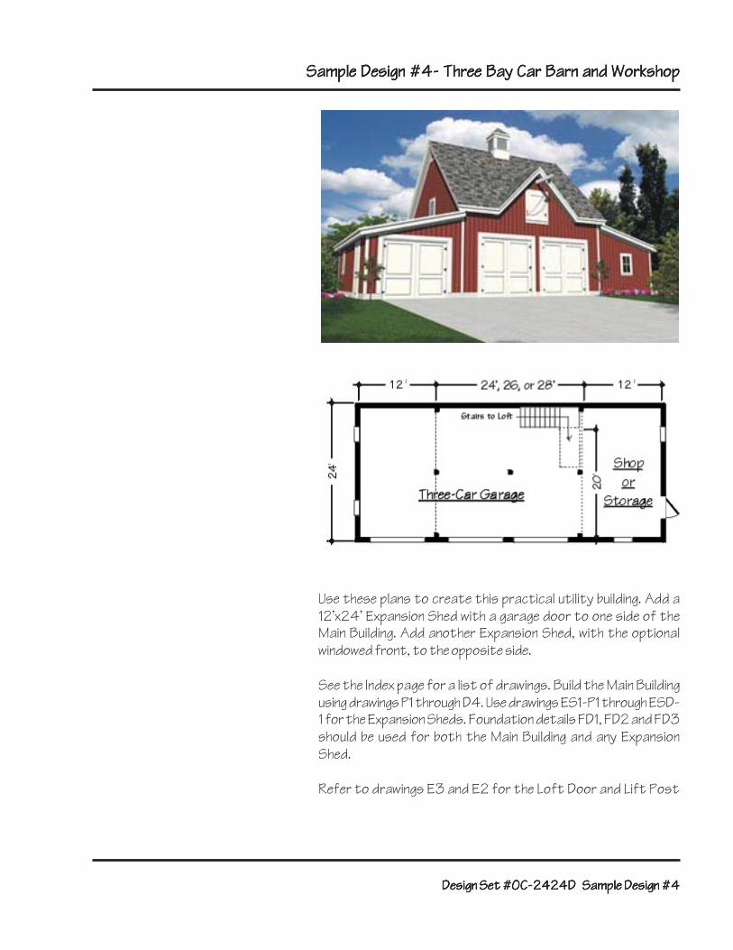
TERMS OF USETERMS OF USETERMS OF USETERMS OF USETERMS OF USEBy using these drawings, the builder andproperty owner agree to the followingconditions: These drawings are intended topresent the general layout and appear-ance of the building. They may also serveas a guide to construction in somelocations. The publisher can not assurethat these plans are suitable for alluses, for every site’s conditions, for allcodes, or for all building associations’criteria. It’s both the property owner’s and thebuilder’s responsibility to have thesedrawings reviewed by a local buildingprofessional and by the community’sbuilding and zoning officials prior to thestart of construction. The publisher accepts no liability for anyuse of these plans. The publisher grants the purchaser ofthese plans permission to build one unitof this design. Copying these plans in anyway is a violation of U.S. and interna-tional Copyright law. DESIGN CRITERIADESIGN CRITERIADESIGN CRITERIADESIGN CRITERIADESIGN CRITERIAThese plans were designed to meetgeneral standards and average weatherand soil conditions. They must bereviewed and adapted by a local buildingprofessional for suitability to the actualsite and for compliance with currentcodes, ordinances and standards. The building was planned as a non-habitable utility or accessory building. Itmust be built at a distance of more than5’ from any adjacent combustiblebuilding. It was designed to exceed therequirements for an A.S.C.E. Category 1building with the following criteria: 70psfGround Snow Load (Reduced to 40psfDesign Snow Load per A.S.C.E 7-95);5psf Roof Dead Load; 40psf Loft LiveLoad; 10psf Loft Dead Load; 90mphWind Load (10psf plus wind force);1,500psf Soil Bearing Strength. The Loft is intended for light storage,typical of a residential attic. The Loft’sfloor structure must be adapted by alocal construction engineer for storageof lumber, metal, logs, hay or masonry,or for any operating machinery.DESIGN CHANGESDESIGN CHANGESDESIGN CHANGESDESIGN CHANGESDESIGN CHANGESThese plans are intended to be suitablefor use with various finish materials andwith other sizes and locations of doorsand windows. The materials, windows and
doors shown are suggested as reason-ably inexpensive and available nation-wide. For best appearance, the buildingshould be finished and detailed tomatch or complement adjacentbuildings on the site. Different oradditional windows and doors may beinstalled using conventional framingmethods. All changes should be coordi-nated by a local building professional,prior to the start of construction.SIDINGSIDINGSIDINGSIDINGSIDINGAny of a variety of siding materials maybe used on this building. Follow manufac-turers’ or suppliers’ recommendationsfor the installation and finishing ofsiding. Siding should be applied over 1/2”exterior grade plywood.ROOF MATERIALSROOF MATERIALSROOF MATERIALSROOF MATERIALSROOF MATERIALSAny of a variety of roof materials maybe used on this building. They should beapplied over a minimum 5/8” exteriorgrade plywood deck. The plywood deck isan important structural element andshould be installed regardless of theroof material used. Metal roofingshould be installed to themanufacturer’s specifications onsleepers or fasteners applied to theroof deck. Wood shingles should benailed to wood sleepers above theplywood deck. For slate, clay or ceramictile roofs, use 3/4” exterior gradeplywood for the roof deck and decreasethe roof rafter spacing to 12” oncenter. Follow manufacturer’s orsupplier’s recommendations for theinstallation and finishing of roofing.OPTIONSOPTIONSOPTIONSOPTIONSOPTIONSThis building is designed to accommo-date optional expansion sheds, layouts,materials and details. The owner andbuilder should coordinate the selectionof all options prior to the start ofconstruction. Expansion sheds must becarefully aligned with the main buildingso that adjacent sheathing and sidingare flush.SITE DESIGNSITE DESIGNSITE DESIGNSITE DESIGNSITE DESIGNThe building should be plotted on itssite by a surveyor or building profes-sional. It must be located at least 5’away from any other combustiblebuilding. Review local ordinances forrequired setbacks. If the building isintended to shelter animals, review localHealth Department regulations for
required distances from wells andresidences.DRAWING NOTESDRAWING NOTESDRAWING NOTESDRAWING NOTESDRAWING NOTESLumber sizes shown on these drawingsare nominal unless marked as “true.”Lumber marked “P.T.” is to be pressuretreated.GENERAL SPECIFICATIONSGENERAL SPECIFICATIONSGENERAL SPECIFICATIONSGENERAL SPECIFICATIONSGENERAL SPECIFICATIONS1. CodesCodesCodesCodesCodes: All work must comply withcurrent codes, ordinances and industrystandards.2. PermitsPermitsPermitsPermitsPermits: The builder is responsible forobtaining and paying for all necessarypermits, scheduling all required inspec-tions and obtaining a Certificate ofOccupancy.3. Scope of WorkScope of WorkScope of WorkScope of WorkScope of Work: The builder shouldprovide all materials, labor and equip-ment required to complete the building inreasonable time. The builder shouldprovide, supervise and coordinate allnecessary subcontractors. All work-manship and materials must be of thebest quality. Materials and equipmentmust be installed or applied to themanufacturers’ and suppliers’ specifica-tions.4. Work by Owner/OthersWork by Owner/OthersWork by Owner/OthersWork by Owner/OthersWork by Owner/Others: All workrequired for a complete and finishedbuilding should be provided by the builder,except as acknowledged by the owner atthe time of the contract agreement.5. General ConditionsGeneral ConditionsGeneral ConditionsGeneral ConditionsGeneral Conditions: The buildingcontract will be governed by standardsoutlined in the “General Conditions ofContract” published by the AmericanInstitute of Architects unless compa-rable published standards are mutuallyaccepted by the owner and the builder.6. Site Work:6. Site Work:6. Site Work:6. Site Work:6. Site Work:1. Clear the building site of all shrubs,trees, rocks and stumps. Remove andstore topsoil. Protect all other land-scaping, paving and structures fromdamage by this construction.2. Excavate for footings to the depthshown on drawings or deeper, if neces-sary, to reach solid stone or undis-turbed soil that’s entirely free ofbackfill. Footings must extend below theestablished frost line at the buildingsite.

NOTES N2NOTES N2NOTES N2NOTES N2NOTES N2
Excavate as required for all planneddrives, parking areas and utility lines.3. Provide clean gravel fill as shown onthe drawings and as necessary to allowa flat, well drained building subfloor.4. Grade the building site so that waterflows away from the building. Replacetopsoil to a minimum of 3” deep. Raketo remove all surface rocks, roots anddebris, and seed and mulch as required.7. Concrete:7. Concrete:7. Concrete:7. Concrete:7. Concrete:1. All concrete must be a minimum of3000 psi and must be handled andinstalled to the American ConcreteInstitute’s standards.2. Concrete slabs must be a minimum of4” thick, reinforced with 6x6 (#10) wiremesh. Provide 1/2” neoprene or oiled feltexpansion joints as shown on drawings.Slope floor slab toward the largestdoor at 1/8” per foot. Provide asmooth, trowel or brush finish.8. Carpentry:8. Carpentry:8. Carpentry:8. Carpentry:8. Carpentry:1. All framing lumber must be structuralgrade, with a min. 1,200 psi bendingstress rating.2. All framing must be plum, level andtrue and must be properly nailed,screwed or bolted.3. Roof sheathing must be min. 5/8”CDX plywood. Exterior wall sheathingshould be min. 1/2” CDX plywood.4. Provide bridging or solid blocking atthe midpoint of all joists that exceed10’ in span.9. Structural Connections:9. Structural Connections:9. Structural Connections:9. Structural Connections:9. Structural Connections:1. Follow manufacturers’ nailing orbolting specifications for all metalconnectors.2. Loft Steel Joist Hanger to BeamConnections: Follow manufacturer’snailing specifications.3. Rafter to Roof Plate Connections:Birdsmouth each rafter for minimum 2"bearing surface. Anchor all rafters atthe top plate with steel framinganchors, Simpson Strong Tie #H1 orequal. Follow manufacturer’s nailingspecifications.4. Additional wind resistance can beadded with metal strapping and ridge-to-rafter connectors. Follow manufac-turers’ specifications for nailing orbolting.5. Plywood: Nail all plywood to raftersand studs with 8d Common Nails or 10DBox Nails - 6" on center for all outside
edges and 12" on center on the plywoodpanel field. 6. Wherever metal connectors, an-chors, fasteners, bolts, screws or nailsare in contact with pressure treatedwood, they must be hot dip galvanizedor stainless steel. Follow recommenda-tions of wood suppliers and connectormanufacturers.10. Roofing:10. Roofing:10. Roofing:10. Roofing:10. Roofing:1. Roofing shall be as selected by theowner, and installed to themanufacturer’s or supplier’s standards.2. All roof valleys, intersections andprotrusions must be flashed with solidlybacked aluminum or copper sheeting andmust be entirely weatherproof.3. Provide metal drip edging at all rakesand eaves.11. Windows and Doors:11. Windows and Doors:11. Windows and Doors:11. Windows and Doors:11. Windows and Doors:1. All prefabricated windows, doors,hardware and accessories must be asselected by the owner, and must beinstalled and finished to the manufac-turers’ specifications.2. The builder must make every effortto build custom doors that arestraight, true, serviceable and durable.3. Provide durable drip caps above allwindows, doors and framed openings.....12. Finishes:12. Finishes:12. Finishes:12. Finishes:12. Finishes:Paint, stain or finish as selected by theowner and to the manufacturers’specifications.13. Plumbing and Electrical:13. Plumbing and Electrical:13. Plumbing and Electrical:13. Plumbing and Electrical:13. Plumbing and Electrical:If required by the owner and the in-tended use of the building, provide aplumbing system and an electricalsystem in accord with all state and localordinances. The builder must secure allnecessary design, permits, inspections,approvals and Underwriter’s certifi-cates.
CONSTRUCTION RESOURCESCONSTRUCTION RESOURCESCONSTRUCTION RESOURCESCONSTRUCTION RESOURCESCONSTRUCTION RESOURCES1. Engineering:1. Engineering:1. Engineering:1. Engineering:1. Engineering: All stock plans like these are designedto work in limited locations. To complywith specific local building codes,ordinances and weather conditions andfor the best quality of constructionthese plans must be reviewed, andmodified as necessary by a ProfessionalEngineer. These drawings must be reviewed andmodified for higher wind resistance, forearthquake resistance, for higher snow
loads and for sites with poor or poorlydrained soil conditions. California,Pacific Coast and Rocky Mountainlocations may necessitate modifica-tions for earthquake resistance. Highmountain locations and areas ofnorthern Maine and northern Michiganmay require higher snow load resis-tance. Florida, Long Island, coastalareas, high mountain areas and someother locations will require higher windload resistance. Many northernlocations will require deeper footingsbecause of deeper frost penetration.The states of Florida and Nevada, andsome other jurisdictions require thatdrawings be prepared or reviewed by anin-state architect or engineer. Somelocal building officials will waive somerequirements if the building is plannedfor agricultural use or for propertythat is zoned as Agricultural. Building departments may providenames of qualified ProfessionalEngineers. The National Council of Examiners forEngineering and Surveying lists thewebsites of Licensing Boards for all USstates and territories:www.ncees.org/licensurewww.ncees.org/licensurewww.ncees.org/licensurewww.ncees.org/licensurewww.ncees.org/licensureMost of those websites have lists oflicensed Professional Engineers.2. Building Components:2. Building Components:2. Building Components:2. Building Components:2. Building Components: A variety of specialty products forthis building can be found on theInternet. The Building HelpBuilding HelpBuilding HelpBuilding HelpBuilding Help resourcedirectory at www.todaysplans.comwww.todaysplans.comwww.todaysplans.comwww.todaysplans.comwww.todaysplans.comfeatures overhead doors, wrought ironhardware, barn doors, rolling trackhardware, carriage house style garagedoors and much more.3. Cupolas:3. Cupolas:3. Cupolas:3. Cupolas:3. Cupolas: An optional cupola for this designshould be a minimum of 30” wide oneach face of its base and a minimum of40” in height above the building’s ridge.It should be centered on the main ridgeas shown on the Elevation drawings. A selection of prefabricated cupolas,cupola plans and weathervanes can befound in the Building HelpBuilding HelpBuilding HelpBuilding HelpBuilding Help resourcedirectory at www.todaysplans.comwww.todaysplans.comwww.todaysplans.comwww.todaysplans.comwww.todaysplans.com .

Sample Design #1 - Two Car GarageSample Design #1 - Two Car GarageSample Design #1 - Two Car GarageSample Design #1 - Two Car GarageSample Design #1 - Two Car Garage
This two-car garage is referred to as the “Main Building” through-out this set of plans. It’s the core of all the possible designs. Itcan be built at the optional widths shown above, with a full stair-case to the Loft or with innexpensive pull-down stairs, and witha variety of exterior finishes and details.
See the Index page for a list of drawings. Build the Main Buildingusing drawings P1 through FD3.
Design Set #OC-2424D Sample Design #1Design Set #OC-2424D Sample Design #1Design Set #OC-2424D Sample Design #1Design Set #OC-2424D Sample Design #1Design Set #OC-2424D Sample Design #1
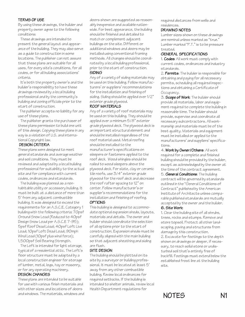
Sample Design #2 - Three Bay Vehicle BarnSample Design #2 - Three Bay Vehicle BarnSample Design #2 - Three Bay Vehicle BarnSample Design #2 - Three Bay Vehicle BarnSample Design #2 - Three Bay Vehicle Barn
Add a 12’x24’ Expansion Shed to either side of the Main Build-ing to create a three-bay barn for cars, trucks or other ve-hicles.
See the Index page for a list of drawings. Build the Main Buildingusing drawings P1 through D4. Use drawings ES1-P1 through ESD-1 for the Expansion Shed. Foundation details FD1, FD2 and FD3should be used for both the Main Building and any ExpansionShed.
Refer to Drawings E3 and E2 for the Loft Door and Lift Post
Design Set #OC-2424D Sample Design #2Design Set #OC-2424D Sample Design #2Design Set #OC-2424D Sample Design #2Design Set #OC-2424D Sample Design #2Design Set #OC-2424D Sample Design #2

Sample Design #3 - Four Car Coach House Style GarageSample Design #3 - Four Car Coach House Style GarageSample Design #3 - Four Car Coach House Style GarageSample Design #3 - Four Car Coach House Style GarageSample Design #3 - Four Car Coach House Style Garage
Add a 12’x24’ Expansion Shed to each side of the Main Buildingto create a four-bay garage.
See the Index page for a list of drawings. Build the Main Buildingusing drawings P1 through D4. Use drawings ES1-P1 through ESD-1 for the Expansion Sheds. Foundation details FD1, FD2 and FD3should be used for both the Main Building and any ExpansionShed.
Design Set #OC-2424D Sample Design #3Design Set #OC-2424D Sample Design #3Design Set #OC-2424D Sample Design #3Design Set #OC-2424D Sample Design #3Design Set #OC-2424D Sample Design #3
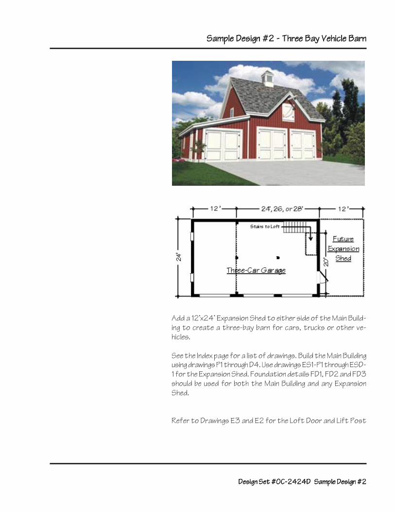
Sample Design #4- Three Bay Car Barn and WorkshopSample Design #4- Three Bay Car Barn and WorkshopSample Design #4- Three Bay Car Barn and WorkshopSample Design #4- Three Bay Car Barn and WorkshopSample Design #4- Three Bay Car Barn and Workshop
Use these plans to create this practical utility building. Add a12’x24’ Expansion Shed with a garage door to one side of theMain Building. Add another Expansion Shed, with the optionalwindowed front, to the opposite side.
See the Index page for a list of drawings. Build the Main Buildingusing drawings P1 through D4. Use drawings ES1-P1 through ESD-1 for the Expansion Sheds. Foundation details FD1, FD2 and FD3should be used for both the Main Building and any ExpansionShed.
Refer to drawings E3 and E2 for the Loft Door and Lift Post
Design Set #OC-2424D Sample Design #4Design Set #OC-2424D Sample Design #4Design Set #OC-2424D Sample Design #4Design Set #OC-2424D Sample Design #4Design Set #OC-2424D Sample Design #4

i
o.n
NLo(oN
.f\\
- f f i4
r lI ]
13 --)F__L_
Main 7uildinq
. t t H--s, ' -+- lE
r--VF{'1- l lEl
t f
74-j>
aII:IIl - -
Kefer to paqe 72 for NotesMirror thie drawing for an oVpooile orientation of thei staire and walk door
I--rI
Noie
Q - Center line of buildin1 and expanoion joint in floor elab
ff i- OxA ToeN on anchored ?ost mounl
Up to Loft
r-,
r-lb
IsL
FsII
III
III
I
III
I
I
i
o
L
orO
N
II
I_ B
L-
aII
I
e te*l
q
1/4'� - 1'�-O"

MAIN FUILDING FLOOR TLAN NOTEg - 1EE TLAN T11. Frost wall or monoli thic slab foundalion - 1ee drawinas FDl and FO22. Thickened 7lab - )ee drawinq FO33. 3O"x3O"x1B" OeeV concrete Vootfootinq
- ioolahe with exVansion jointo
4. 4" Reinforced concref,e elab oloVe towards larqe doors aI1/9" per foof,
5. Min.3'-O" x 4'-O" concrele ohoop att'he level of the building floor
6. Concref,e a?ron, or oloVe driveway uV to the level of the buildinq floor7. 2xO jtud wall with sbuds at, a maximum of 24" on cenlerB. 112" Tlywood bracing Vanel
- Nail aN 6" O,C. to all studs, Voolo and braces9. b'-O" or 9'-O" wide overhead 4araqe door or two 4'-O" wide hinqed doore.
Theee doors should be T-O" or B'-O" high, wiNh opf, ional12" hiqh Iransom window above1O. 3'-O" wide x7-O" hiqh walk door11. 2'-O" wide x3'-O" high f ixed, awning, caaemen| or double hunq windows12.7rovide code-comVlianl straircase, handrai l and Loft rai l inq13. Area of oVtional ExVanoion Shed - )ee ExVanoion Shed drawinge14. Fronv corner dimeneiono vary with lhe oVbional widbh of f ,he bui ldinq and with the optional
K.O. widLh of the doors. Front, corner dimensions should be eaual and should be a minimum of 1'-1O"
15. Line of Loft oVeninq above.Refer lo manufacf,urerl' specificabions for R.0.s of doors and windows
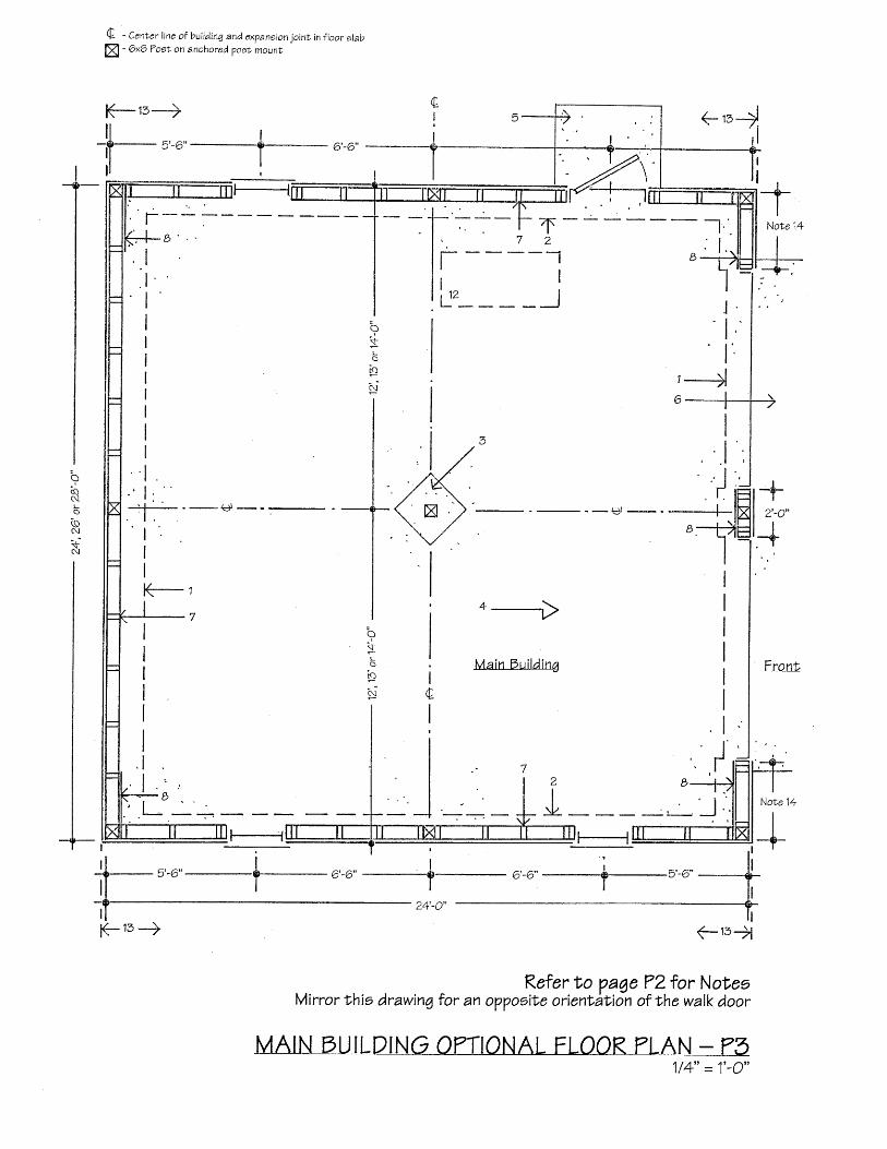
MAIN FUILDINO ONIONAL FLOOR TLAN NOTE9 _ 1EE TLAN T51. FrosN wall or monoli thic slab foundatr ion - )ee drawinae FDl and FDZ2. Thickened Slab - )ee drawinq FD73. 3O"x3O"x1B" DeeV concrele ?06I footinq - isolate wibh exVansion jointo
4. 4" Keinforced concrele slab oloVe towarde larqe doors at 1/8" Ver footr5. Min.3 ' -O" x4 ' -O" concre le oLoop aNNhelevel o f thebui ld inqf loor6. Concrele a?ron, or oloVe driveway uV f,o Nhe level of the buildinq floor7. ZxO Stud wall wibh shuds al a maximum of 24" on cenlerB. 112" Tlywood bracinq panel - Nail al 6" 0.C. to all sf.uds, Voete and braces
9. 8'-O" or 9'-O" wide overhead qaraqe door or trwo 4'-O" wide hinqed doors.These doors should be 7-O" or b'-O" high, wi6h oVtional12" hiqh traneom window above
10 . 3'-O" wide x T -O" hiqh walk door11. 2'-O" wide x3' 'O" high f ixed, awning, caaement or double hung windows12.?ul l-down otairs to lof l - Frame with double Loft, joiebe and double 2x1O blockinq
13, Area of oVlional ExVanoion thed - 7ee Expanoion thed drawinge14. Front, corner dimension; vary wiNh the opNional width of the bui lding and with Nhe oVbional
R.O. widlh of the doors. Fronl corner dimensions should be equal and should be a minimum of 1'-1O"
Refer lo manufacNurer;' specifications for K.O.s of dooro and windows
e
I
NL
(9\ \\N
Q - Center line of building and expaneion joint in floor slab
ffi - 6x6 Tost on anchored poet rnount
t(_-1b--) +''rjl
t . ' . t :
_l'
.a-j*
---€-III
Note 14
,-JAv
HHEI
II
, . . 1I
. r . l= , - - | |
B.t)II
t +I o'-.'r+
o---r)
Main Oui ld inT
Kefer 1o page ?2 for Not,esMirror this drawing for an o??ooita orientaNion of the walk door
Note
II
A
z+-u
a
oI
:+\L
rc)
n !
2
J
f-15+iK- 13 -)
1/4" = 1''O"

F-'' -+
D o w n t o M a i n L e v e l
3'�-6" Min.
. / ^ \upen J
a
I
+\:o
F$IIIITIIII
II
III
It_p-I
{lIFid!r!
Kafer to page 76 for NotreeMirror t'his drawing for an o??oeite oriitntation of the stairs
MAIN FUILDING LOFT FKAMING TLAN - T41/4" = 1'-O"

I I
l lKt-'l+l l
€-reti*l
I r4 " ' C -
IIrIIII
IIItI
a
\-J
*L
o
FN
(- rs
Keter to Vaqe 76 for Noi,es
114' = 1'-O*
Center l ine of Kidqe
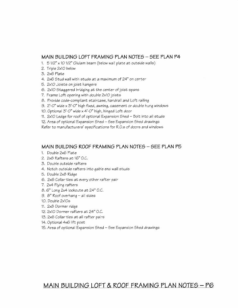
MAIN FUILDING LOFT FRAMING TLAN NOTEg _ 1EE TLAN 741. 51/2" x10 1/2" Glulam beam (below wall plabe af, oubside wallo)2. TriVle 2x1O below3. ZxO TlaNe4. 2x6 1rud wall wibh etuds al a maximum of 24' on cenler5. 2x1O JoisLs on joiot hanqero6. 2x1O )taqgered bridging aN the cenLer of joiel o?an67. Frame LofL opening wiNh double 2x1O joiotoB. Trovide code-compliant slaircase,handrai l and Loft rai l ing9. 2'-O" wide x3' 'O" hiqh t ixed, awninq, caoemenl or double hunq windows10. OVtional3'-O" wide x 4'-O" high, hinged Lofl door11. 2x1O Ledge for roof of oVtional ExVaneion thed - Dolt inLo all studs12. Area of oVNional ExVaneion Shed - 7ee ExVanoion thed drawinqoRefer lo manuf acturere' oVecificabions for R.O.s of doors and windows
MAIN FUILDING ROOF FRAMING TLAN NOTE9 _1EE PLAN P51. Double 2x6 Tlabe2. ZxB RatNers aN16" O.C,3. Double outside rafhers4. Notch outrside raf lers inho qable end wall sNude5. Double ZxB Ridqe6. ZxO Collar lies aN every obher rafEer Vair7. 2x4 Flying rafteroB. 6" Lonq 2x4lookouNs at 24" O.C.9. b" Roof overhanq - all sideo1O. Double 2x1Os11. ZxB Dormer ridqe12.2x1O Dormer rafLers at 24" O.C.13.ZxO Collar Nies aN al l rafLer pairo14. Optional 4xO lifL VooI15. Area of oVtional ExVanoion thed - )ee ExVanoion Shed drawingo
=--?
<nM
Ift
ast q)i isl
d r M
iq
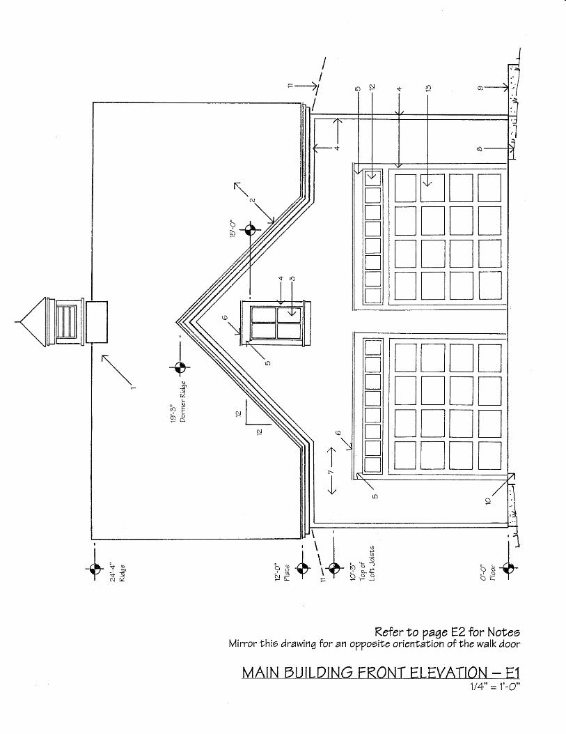
Refer to Va6e EZ for NoteeMirror this drawinq for an o??oeite orientAtion of the walk door
MAIN FUILDING FRONT ELEVATION - E11/4" = 1'-O"
I ^ .
Y + l1 , N\\ d-
I!II
/ ]U 'Y
s.)_\ML
. o
' t ' r
4I
tr-II
{/
TNlnnnTN
TL_ln
lnll
unlnnTn
uuTuulltl
l r lrTTTTrnnnrnlr

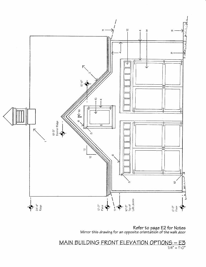
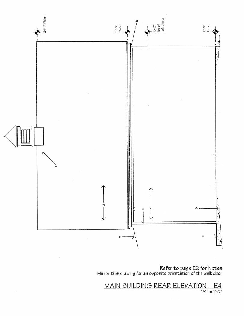
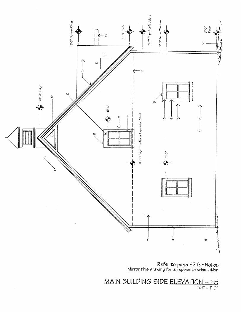
MAIN FUILDING ELEVATION NOTES1EE ELEVATION9 E1, E5, E4, E5 and Eo
1. OVf, ional Vrefab cuVola should be a minimum of 30" wide on each face of i ts baee
and a min imum of 49" h iqh
2. Roofing, al owner'o oVNion, over 5/8" exLerior qrade Vlywood3. 2'-O- wide x3'-O" high f ixed, awning, casemenL or double hung window
4. 1x4 Trim5. 1x6 Trim6. OriV caV7. gidinq, al owner'o oVlion over /2" efierior grade Vlywoodg. gloVe grade away from bui ldinq on al l sides
9. ConcreLe otooV1O. Concrete aVron, or oloVe driveway uV No the level of fhe f loor slab
11. Line of oVtional ExVanoion thed - 6ee ExVaneion Shed drawin7o
12. 12" hiqh, cusi lom f ixed glaoo Nransom window - OVNional on al l doore,
but recommended for 7-O" high vehicle doors. Mount 1xO tr im and driV caV
directly above doors when f,raneom window is not' ueed
13. g'-O" or 9' 'O" wide xT-O" or B'-O" hiqh overhead qaraqe door
14. )phional hinged doors - Two +'-O" wide xT-O" or B'-O" high hinqed doors,
15. OVhional3 ' -O" wide x 4 ' -O" h igh,h inqed LolE door
16. Optional 4xO Lifl ?oeN - MounL on triVle ZxB header al ouf'side wall and aecure
i lghfly Lo the undereide of three col lar t ies with si leel otraVVinq or anqle brackets
17. Screened and louvered venN10. 3 ' -O" wide xT-O" h iqh walk door
19. 2'-O" wide x3'-O' hi4h f ixed, awniny, casemenl or double hung window if
ful l staircaae is noL used - 7ee Vain Suildinq )Vi ional Floor Tlan 73
=*--?
<nM
V .tJ. ^ r _ *\ ! n
(t)
rS)
- ' s c F. \ o o
1I
tII
III
t
Refer to paqe E2 for NotresMirror this drawingfor an o??oeite orientation of thewalk door
MAIN FUILDING FRONT ELEYATION OTTION9 - E51/A" - 1 ' -n"t t I v
Ttl[]utlun
ntrltnil-_lll r r l
titltrltntri
Il .
- & T R .v + s
I N 0 l
. ;? - \ ^ o o I I- r k \ I ts t r + !
, tI
I
a,)
_\0l
{" :N+
15!P.9
i'r '6 -)
r \ o ob Fb d -#
l t
<ilw
Kefer to page E2 for NotesMirror thie drawinq for an o??ooit'e orient ation of bhe walk door
MAIN FUILDING REAK ELEVATION - E41/4" = 1'-O"
t f ; lT +{ l
Kefer to paae E2 for NotesMirror this drawing for an' op-poeite orienlation
MAIN FUILDING 9IPE ELEYATION - E51/4" = 1'-O"
<rM
.t\:.II
lz- -N
-sc.)
S)-.o\')ENs-xLUGg
Fo_
St\J
(o
i
oI
pI
/l{.a
\Er-/II
1J
\:t'
II
+
J
I
!j
!€d)I
IIII
lO t rc)

II+IIII
rr)Ll
.q
k r o )l n , r
\ J . V Y
q)
stsi /
\- iTN
?1t-- t i -
II
III
<rM
II
Kefer to paqe EZ for NoteeMircor thie drawing for an' o??ooite orientation
MAIN FUILDING gIPE ELEVATION - E61 la" - 1'-n"
l l I v
r ' lI
i
II
r ll rt+l
\t
I+
?\
tf)
I
aD- to
Y Ir lr $ /
\q)-
S)E'$
Ns-xLU
Gg
Fs-
q)
\q)
J
\J
= o
\s( \ L
. . = xi ' - ( \ - : z
N € = ;
;I
{/
rs\

.C\
L
I
i-.-
rti+tst' O O
o N
e Io \q _ g
, O Nr ts)
- i N
+I
III
+IIIIII
I
(\s
Fo_o \u o
; os , t r
\ oJ E
* ; \- ' x= ! u
q)
N
u_oN
I
II^-s-
Ri I
6z
P --+1
Kefer to paqe 92 for NolesMirror this drawing for an o??oeite orienlation of thti st'airo and walk door
MAIN FUILPING FKAMING 9ECTION _ 911/4" - 1'-O"

MAIN FUILDING FRAMING 'ECTION NOTE91EE DRAWING 91
1. Double 2xB ridge2, ZxB Root rafhers at,16" O,C,3. Roofing, aN owner'o option, over 5/8" exlerior grade Vlywood deck4. ZxO Collar Lies aI every obher raft,er Vair5, Double ZxO Vlate6. 1/2" Tlywood loft, floor deck7. Line of 2x1O ledge of oVtional ExVansion thed - see ExVanoion ghed drawingob. Nolch studs inNo oulside raff,ere9.Tr iV le 2x1Os acro66 gable ende10.2x1O Loff, f loor joiolo, on joiot hangero at 16" 0.C.11. 2x1O Staqgered bridqing at the cent er of joioL 6?ane12. 5 1/2" x 10 1/2" Glu lam beam13.ZxO stude aN 24" 0.C. on ZxO si l l plaNee14.2xO HorizonLal blockinq aN 4'-O" O.C.15. 7rovide code-comVlianL et aircase, handrai l and Loft, rai l inq
Trefab pull-down slaire may be eubetibuted for thie ef,aircase. eeeOplional Floor Tlan 73
16. Nail ful l-hei4hf,,1/2" Vlywood Vanelo to al l etude, Vooto and bracee at,cornero ana belween vehicle dooro. )ee Tlans 71 and 72 for locationo"
17. Oplional Lransom window19.)ee Drawinge FD1, FOZ and FDZ for concref,e detai ls19. SloVe 7rade away from bui ldinq on al l sidee.20. ConcreLe aVron or oloVe drive uV lo f loor level21. Treeeure Lreatred ZxG plaLe
22. 6xO ?osi ls on anchored VooL mounle and ZxO sLud wall23.1idinq,aL owner'6 oVlion, over 1/2" exf,erior grade Vlywood24. 6xO Toel on anchored VoeI mounf,25. Undereide of the slair Vlatform ehould be a minimum of 4'-O" above the
floor to allow o?ace for Varkinq lhe fronf, of cars and f,rucko below lhe
4able-eide stairs26.2x8 Dormer r idge27.2x1O Dormer raflere at 24" 0.C.29. Oouble outside raff,ers29. 6" Lonq 2x4 lookouts at 24" 0 ,C.3O.2x4 Flyinq raflers31. OVLional 4xO Lif t poer - Mount on tr iVle ZxB header al outside wall and eecure
tighrly Lo lhe underside of three col lar Nies with sLeel etrappinq or anqle braces32.Triple Zxb header

2x4 Flying rafLer
2x4 x 6" Lookout
, / '
12'-O" ?lat'e
Double ZxO plaNe
LQF-I
'* lT
,/, ^,7
+-4
- -
Double outside rafEere
11'-6" Ledqe of optionalExpanoion thed
MAIN FLIILD]NG
G_L1LE-E.ND€
3 >4 ----)
5-__>
-: s-t| . - -, - - ' I1 1
<_e -+ToV of Loft joioto.And beams
51/2" x lO 112"G lu lambeam
MAIIIF_UILPJNG
Siding ai
owner'g
oplion,
over 112"
exLerior
grade
plywoodoheathing
EAVE 9JD7]5O'-O" Floor
tz1 1 2 +
1. Koofin4, al owner'o oVt'ion, over 5/8" erLerior qrade Vlywood oheathing
2.Zxb Roof raflero - 16" 0.C. DirdsmouLh for a minimum 2" bearin4 at 2late3.DriV edqe 4.1x2 5.1xO 6,1x4 7.1/4" Exrer ior Vlywood soff i t
b. Simpoon SbronqTie #H1 or equal metal l ie-down
9.2x1O LofL f loor jo isLs, on jo iot hanqero - 16" 0.C,
10. Secure Loft eil l platre to glulam beam with 112" Diam. x 5" Laq bolt 'o - 4' 0 'C,
11. Oprional Expanoion shed - )ee ExVaneion thed Drawin7o
12, Cont inuouo lermiNe shield below anchored 7.T, Tlat e and poot mounls
(f)zlc)FI()r!qJJ<l=qzldJ=qzl<l ">i q' l ;I c J \(J . ih

ZxG Stud and pla"ve Lof-v knee wall
?ogf, mount
51/2"x10 1 /2"Glu lambeam
6xG ?ost
ZxOandwal l
+- zxlo Joisto onjoior hangera4 - t , / ' \ ^
I O U , V
I\ l
1ll g
t . /l /
l 1
SimVoon SLrongTie# AOU66 or equal
10'-3"ToV of Jois|s
TriVle 2x1Os "
Tost mount) imVeon 1trong t ie
#L?CG or equal
6xO Tost
ZxO 7rudand VlaNe
Tosl mount
-/{-
10'-3"ToV of
G l u l a m e
?'�-41/2"ToV ofTosts
C + ' , ).J VU(A
Vlahe
\\
12',13' or 14'
"Gable-end 2x1Os areouVVorLed by the etuds below.However, tace mount hanqere likeSimpeon Strong Tie # HUCQ7IO-3 may beUEed for added otrenqth and eaee of framing,
\ - - l\ l
\
Il ^t CenLer l ine of Voo-v
L f
\
6/R
G()I l-\
os$oz.
B;
O'-O" Flc,or " Diam. x12" Anchor bolt
+15'�-1" or16 ' � -1" R.O.LofrWindowe
uzl=l<lM'Ll=Oiqzl=qMotaq\zl-.t<l=qZld-.1=nlzl<l +>i ,N
t v rt t
N Rol ;
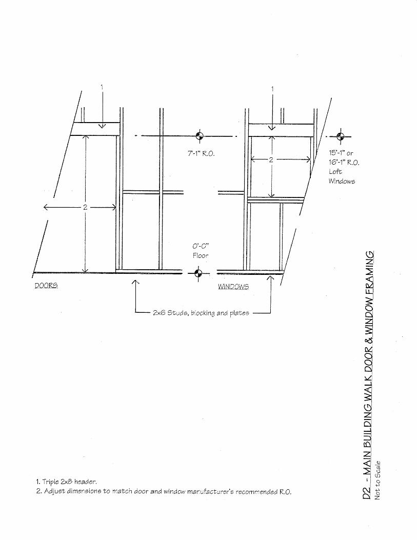
1. TriVle 2x& header.2. Adjuot dirnensions t 'o match door and window manufacturer 'o recommended K.O.
DOOR3

bracee, blockin4 and VlaNee
10'-3"LofE JoieLe
R.O.T-4"e -+-Oouble 2x6o
6xO 7oet,
\J -TJ
Floor
1ZxO 7Ludo,
1" 51 /2 " x1O 1 /2 " G lu lam beam.2. 13" R.O. for cueNom transom window.3. Adjuet dimensions lo maNch door manufacN'rrer 'o recommended R,0.4.7rovide ZxO angled braces between stude adlacentto vehicle doors
and aN al l corners of the Main Dui ld inq5. Nail ful l-heiqht,1/2" plywood Vanele Lo the inLerior sufrace of al l et 'uds,
braces, blocking and pooLo adjacent ' Io the vehicle doors and at ' al lMain Dui ld ing cornere. )ee the f loor p lane for locaLione.
N
$)o$r
z.
10'-3"LofL Joisrs
+-
7tude, bracee, blockinq and Vlaf,eo
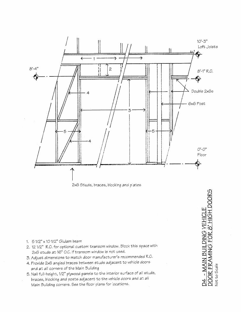
1 . 51 /2 " x10 1 /2 " G lu lam beam
Z. 121/2' R.O. for oVuional cuslom lraneom window. Slockf 'hio oTace with
ZxO studs at16" 0.C' i tNransomwindow ie not , used'
3. Adjuot dimenoions No match door manutacLurer' l reCommended K'0'
4. ?rovide 4xO an4led bracee beLween sNude adlacen|No vehicle doors
and at al l corners of the Main Ouildinq
5. Nail ful l-heighl. ,1/2" plywood 7anelotoNheinlerior surtace of al l sNuds,
braceo, blocking and pooto adiacent to the vehicle doore and at al l
Main gui lding cornero. gee Lhe f loor vlane for locaNiono.
Double 2x6o
6xG Toet'
tIZxO
ulJq
+lqzldJ3nizl<l>l' l\tlAl
so$r
Ff
z.

TermiNe
th ie ld
ZxO Stud wall on continuouo ?reooure treaLed oi l l VlaNeor 6xO oosf, in pogf, mounN
5lB" Oiam. x12" Anchor bolbs
1/2" Neoprene, oi led felt orf ib erbo ard exp anoion joinL
o'-o"'Floor
I-@I
A "+
#4Verl ical reDar wif,h 4" "L" bend - 36" 0.C.
#4 Cont inuouo rebaro
+ 1o"vin.4 Dotlom of footinq musN be belowthe local frosL l ine
?rovide anchor bolrs aN each VoeL mounf,, wiLhin 12" of al l si l l ends and corners, and a
rnaximum of 6 ' O.C.Each secf , ion of o i l l V late musNhave a min imum of Nwo anchorbol tE.
Foundat ion wal l may ex\end above the f loor olab height to adjuoN f ,o the s i le 's oloVinq 7rade.
Foundat ion wal l may be Lhickened and notched to al low slone or br ickfacing.
l.D.]s
r t ' r , X
s -rSr
-9 sr$ E\ - n\\ a\
x $ )L U g
5 af f i - :\ ! L
o NP q :| \ \G S
O \s,s 3N V
- Q )-< c\
q ) r--s c\i-r No.-
F . -
s, _g
( s -= P$ o
S E9 s;. --Y q >N ( -
$ - -nr l-l
{ xP Yr- +-
q _ v' ( -= $
'^-
}J
N q )r ( - -\ -=S S
R rslq _ L
r n . Y
(- ir\.r- ()$ O
T ;__J -=
3'�-O" Min.

Termitethield
ZxO et.ud u,all on conlinuoue ?re66ure lreaf,ed oil l Vlaf,eor 6xG ?ost in pooL mount
5/B" Diam.x12" Anchor bol ls
#1O 6xO Wire meeh
o'-o'+Floor I A r t
{ o . '
! ' " .
I
#1r-J\S)\q)
_gS)g
.e$t ,;\_ ur
r s Rs_'=fr \s)s S= q )N -^ . sU ^s ) -N - SL L
, N NI I v
q )
c \ .= RYl rs L*- ' l 5 S r.-l i., =l l l + o
s l P p- l k "I v l
l s r ozl = c.Jo ; R- t d \ -I I v . !
l-l \ +rU's, s ,lI! $, 3(|i K;n l p p<l s=
l l L r< ^ r n
CI i Pg s E
| ; >-rl \\ .ll
t - l i pr l - -- l J d \
. i v
-t .P -so ; :z i i HC ) ; R=I PK- - i u ( )
l l $ o
N F - =A I R=tll 5 6
Trovide anchor bol ts at , each VooN mounN, wi th in 12" of a l lmaximum of 6 ' O.C. Each eecl ion of s i l l VlaLe mueN have a
TB" Clean 4ravel
#4 ConLinuouo rebars
s i l l ende and cornere , and amin imum of two anchor bo lLe .
*-,, -+

TermiLeShie ld
U . U
F loo r
ot ,I
{Jo12"
?rovide anchor bolrs at each poet mounl, wibhin 12" of a l l
maximum of 6 ' O.C. Each secl ion of s i l l p la le musL have a
ZxO Stud wall on conLinuouo ?reesure treated oi l l Vlateor 6xO ?oot in VoeN mounL
5/b" Diam. x12" Anchor bolts
#1O 6xO Wire mesh
rebars
s i l l ende and corners , and a
minimum of f ,wo anchor bolLs,
\s;\
q)
_g
\ J J
r.9tl)g ,(ss-X
t t I
\S(\q)s)(\t-N( \.S
q)_g
. \c\
]!(s=\s\JI
U
50ss)
_trs5-
(+_s
-,7-Ns==o(+-q)
-s+\S)Nrs)
E+tS)
=
t inuouo
I
B" MiN.
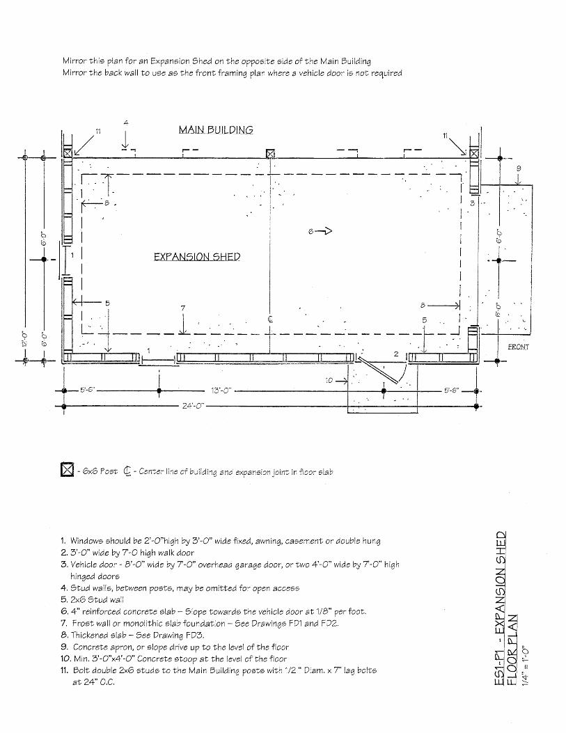
Virror th io Vlan for an Expanoion Shed on Nhe oppooi te s ide of Nhe Main bui ld inqMirror the back wall to Doe ae lhe fronl framinq plan where a vehicle door is nof, required
EXTANSION sHEDI
= l Ft \ ( o
I r-+'-lrb-
o . r lu - - ,1 _I
c l
I
l r
l i+- u-u" + B.a"
I24'-C"
q
X 6xO ?oec C- - Cen-,er l ine af bui lding and exVansion ioint, in i ioor elab
1. Windows should be 2 ' -O"hiqh by 3 ' -O" wide f ixed, awninq, caoemenT, or double hung
2.3'-O" wide by 7-O hiqh walk doorS,Vehic le door - B' 'O* wiaebyT-O" overhead qaraqe door, or two 4'-O" widebyT-O" hi6h
hinged doors4. )Iud walls, belween Voof,o, may be omitted for open acceeo5,ZxO )tud wal l6. 4" reinforced concreNe slab - 7lope towards the vehicle door at 1/8" per foot,7. FrosL wal l or monol i lh ic s lab foundat ion - 7ee Orawinto FD1 and FDZ.b, Thickened slab - 7ee Drawing FD3,9, Concrele apron, or olope drive uV to Nhe level of the floor10. Min. 3'-O"x4'-O" ConcreNe otoop aN Lhe level of lhe floor11. DolL double ZxO studs to the Main Oui ld ina posvs with 1/2" Diam, x7' laa bol to
aN 24' O.C,
zl<t_lLlM AQ -c) -,,_l l{-ll-I S
MAtl{trll_lLp_lNc
sq)
(t)E's,r
X!u
q)
.g
L
p
c)(J
€ r -
Mirror th io plan for an Expanoion Shed on lhe oVpooite s ide of Nhe Main Sui ld inq
EXTANgION gHED
- _ { J
EXTAN9ION gHED ROOF
21'�-O"
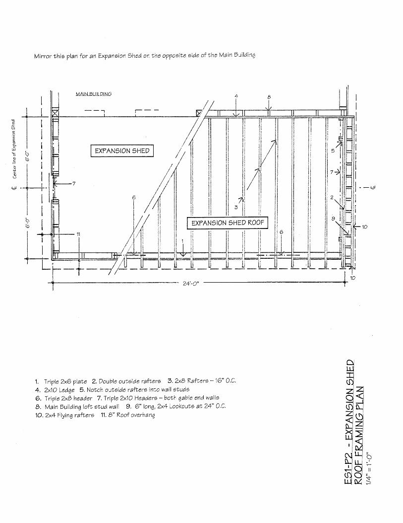
1. Trivle 2x6 vlaLe 2. Oouble ouNside rafLero 3.2x8 RafLero - 16" o.C,
4. 2x1O Ledge 5. Notch outoide raflers into wall sluds
6. Triple ZxB header 7. Triple 2x1O Headero - boNh qable end wallo
O. Ma inbu i ld inq lo f r ' s tudwal l 9 . 6 " lonq ,2x4LookoutE a t24" 0 ,C,
1O.2x4 Flyin7 rafhers 11. b" Roof ove.rhang
c!tr-ljrl$l- lZ ]0sOJ N.i7 d"-l ZiL I I ]q?' l M
r i l !+ l O r ltf)Q +IJ.I M S

Mirror th is elevat ion for an Expanoion Shed on the oVVooi le s ide of I 'he Vain bui ld inq
b'-1" TlaNe
1. Koofinq, at owner's oVLion, over 5/8" erLerior qrade Tlywood deck
2. Flash shed roof in lo Main 7ui ld in4
3, 1x4 trim4. lx6 trim
5. OriV CaV6.9idinq, at owner'e opNion, over 1/2" exberior 7rade Tlywood7. gloVe grade away from bui ld inq on al l o ides
b, ConcreLe oNoop
9. Vehic le door - O'-O* widebyT-O* overhead qaraqe door,
or two 4'-O" wide by 7-O" hiqh hinqed doors
1O. Concret'e apron
t10
\J
t l
+
11'-6* Ledqe
[]N[][]nnnnnnln[][]rrn
Mirror th is elevat ion for an Expanoion Shed on theopVooite s ide of lhe Main Sui ld inq
11'-6" Led7e
B'-1" ?la"ve--+
M a i nbu i ld ing
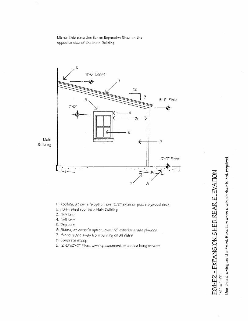
1. Koofing, af, owner'o oplion, over 5/8" exNerior grade Vlywood deck2. Flash shed roof into Main Sui ld ina3. 1x4 trim4. 1xO trim5. Orip caV6. )iding, at, owner'o oVtion, over 1/2" efierior qrade Vlywood7. ) loVe grade away from bui ld inq on al l s idesB. Concrete sLoop9. 2 ' -O"x3'-O* Fixed, awning, cagement or double hunq window
TSc)
.t--t
sq)t-
sos.9t-oo\a)
.9qJ
(\Eq)
+
iso.F(\q)
lll
{.)S
PILosro(\s)S.;($
- ! -
b \. r t $
i l . p
S rs)
77 /

Mirror l 'his eleva-vion for an tr*x?ansion Shed on r,he opVooite side of t 'he Main Duildinq
o
3a s oV S
O S3 ' ;-s- s)
Su --1
S q )s $ 5! - 3 \ s )
! , q)v' . + \ se - i s _ S )
P $ J ^ -q ) = ] l $
' \ ! r? . t r Q) s
\ 6 F o
: s N Pq J \ _ x
B \ 3 Si - = s i ;o " - E s' , = E c S
5 _ 6 = P\ J , , L \ \ q -
-9i . N = e : c \ = S
i t - 5 ' I R P G= \ \ o l r - r \ 6 0 .o S * t - i $ N <+ : P o v R S I
E E \ i i x l r i $ s,' q ' F P " : ' . x . x I h I+ l P . L H ? - . r ' c l : : R -
: s f; f,x { s s fir o d - K t ( g D - d o > 9 =
-\z()U\
-\5
=->
c\
q)-\5Nt-s,t-
"-q)FXq)
au ) s
! - =q) -:l
o 6i - =*"- i
U$ + l'r- g
} Xo i
N d
s) \s)- = r
O r sM u -
- n i
I
il
+1if
L
oil-
a\I
i\
i sl s
A O \
Y -
a
I-fr(s)\q)_t
\)
Mirror Nhio drawinq for anoppooile side of the Main
Exyaneion thed onlheDu i ld ing
b'-1" thed plar,e
$..*_tt v?
4 '
v - u
' - l s I72jQ'�:-ENEAN9IONI9HE'
{: Va|UAUILD-JNG +
l r
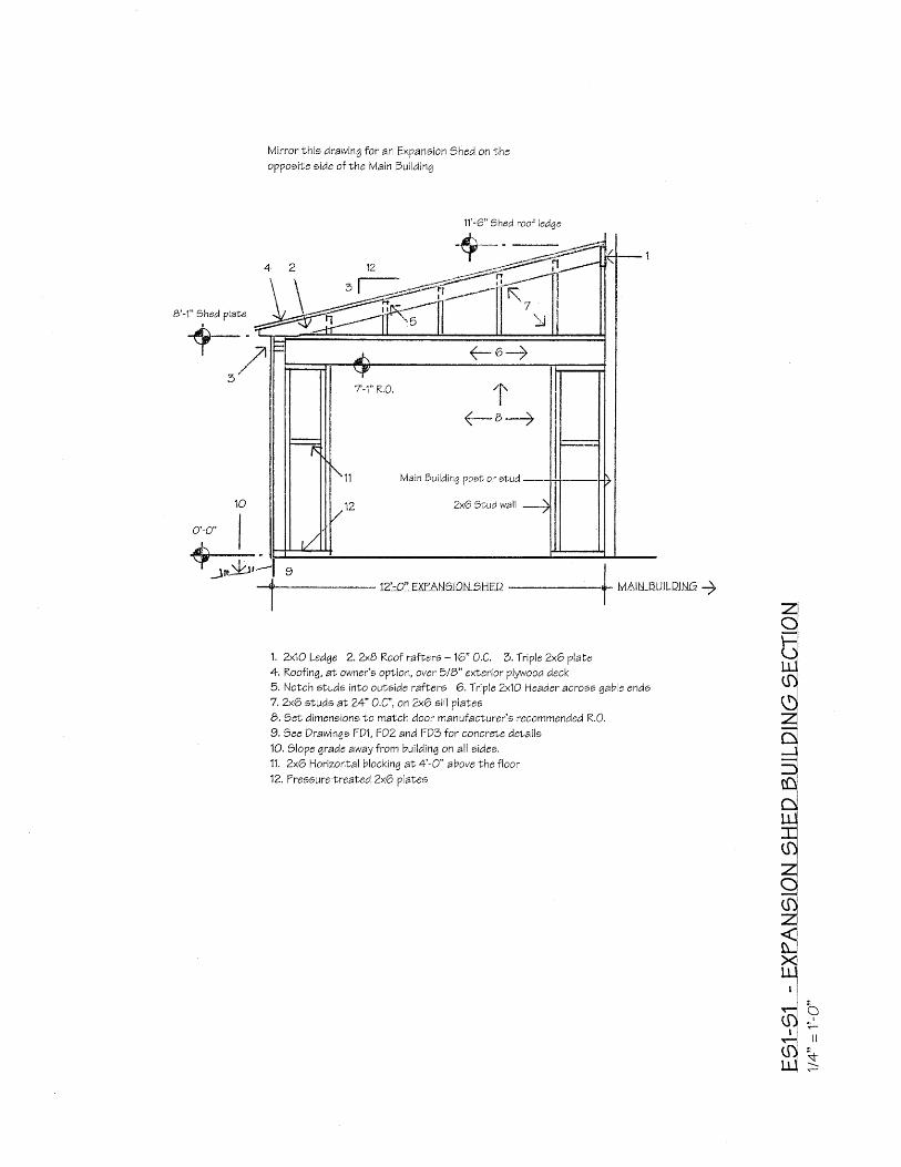
1 , Zx lOLedqe 2 , *BRoo f ra fLe rs -16" O .C . S ,T r ip leZxGp la te4. Koofinq, at owner's option, over 5/b" exEerior pl5wood deck5. Notch aluds inlo oulside ratters 6. Triple 2x1O Head,er acro;o gable endo7 , 2x6 studs at 24" 0,C" , on ZxO sil l plaLeoB. jet ' d imensionslo match door manufacturer 's recommended R,O,
9. )ee Drawinqo FD\, FDZ and FD1 tor concrete delails10, ) loVe grade away f rom bui ld inq on al l a ides.
11. ZxO Horizontal blocking aN 4'-O" above the floor
12, Tressure'treaLed ZxO olales
I
l l
\r
11'-6" Shed roof ledqe
11 Main Bui ld ing pooL or ovud
12 ZxG Studwal l
Mirror this drawing for an Expanoion thed on lheopVooile eide of the Main bui lding
a
I
ZxO grudwal l
$
- 1T-o' shed tedqe
11
ZxO )tudwal l
LOEI
10'-3"
Loft joiot,
\ Triple 2x1Os
MAINEU]LD-INGSAOLEENP
Siding aI
owner's
v Y v t v t t ,
over 1/2"
exLerior
qrade
plywood
oheaLhing
6xO poet
Stud
wa l l6
between
6x6poot'o
may De
omitled
for
o?en
acce96
So'-o"Ftoor-*4
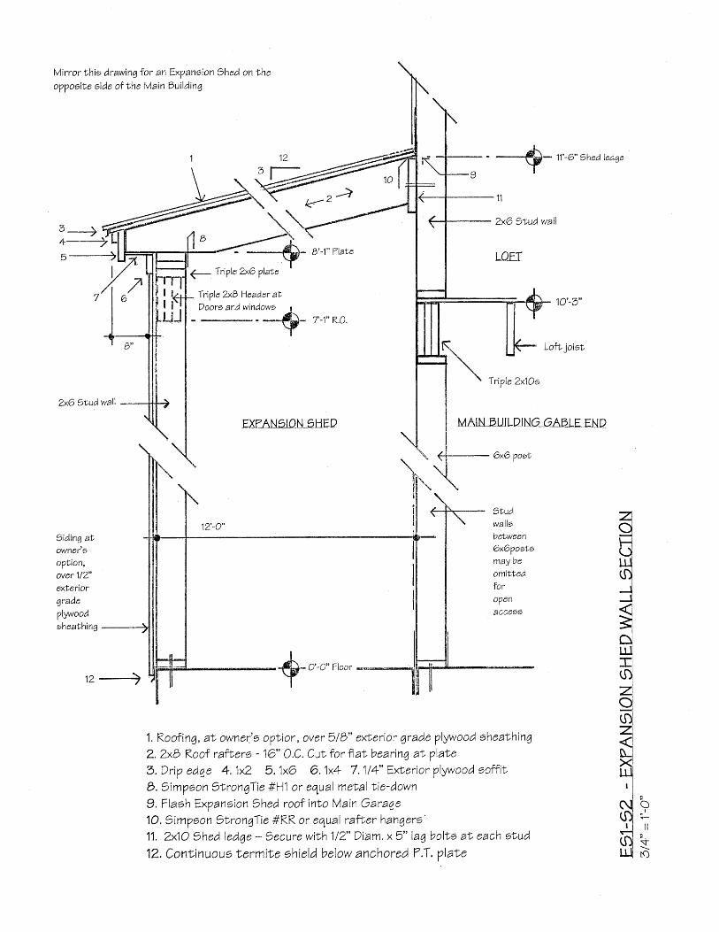
1. Koofin4, at owner'e oVNion, over 5lB" exDerior grade plywood oheaLhing
2. ZxB Koof rafLero - 16" 0,C. CuN f or flat bearing af' plate
3. Drip edge 4.1x2 5,1xO 6.1x4 7.114" ExLerior Vlywood soff i t
B. 7imVeon 7f,rongTie #?,1 or equal metal t ie-down
9. Flaoh Expaneion Shed roof int 'o Main GaragelO.7 imVoon SbronqTie #RR or equal raf rer hangero11. 2x1O thed led7e - gecure wiLh 112" Dram. x5" laq bolts aI each sf 'ud
12, Continuouo lermiNe shield below anchored 7.T, Vlate
12->
r\I
t lI I
d-N)
zo
IL
Eave eide walle Gable ena v,,al i .-
:'eNpcw9
€-1---->
? z*o gtude,)block ing and
Vlatee
Oable end wal ls Eave o ide wal le
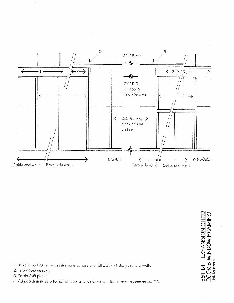
1. TriVle 2x1O header - Header run6 acroes the ful l width of the qable end walle2. Triple ZxB header.3. TriVIe ZxO Vlat e.4. Adjuen, dimensiono f,o maNch door and window manufacLurer'o recommended K,0.
fied=l3#3Hi l=.:l "d{ Ec !M()+I C)S0 i Q *u o z
I
I
--€-I
7-1" K.O.All doorsand windowo