nyu wireless - 5g millimeter-wave channel model …...5g millimeter-wave channel model alliance -...
TRANSCRIPT

5G Millimeter-Wave Channel Model Alliance -Measurement Parameter and Scenario Parameter
Hangsong Yan, George R. MacCartney Jr., Shu Sun, and Theodore S. Rappaport
{hy942,gmac,ss7152,tsr}@nyu.edu
NYU WIRELESSNYU Tandon School of Engineering
Brooklyn, NY 11201
September 9th, 2016
2016 NYU WIRELESS

Measurement Campaigns Conducted
28 GHz Outdoor Cellular Measurement Campaign
73 GHz Outdoor Cellular Measurement Campaign
38 GHz Outdoor Cellular and Peer-to-Peer (P2P) Measurement Campaign
60 GHz Outdoor P2P and Vehicular Measurement Campaign
28 GHz and 73 GHz Indoor Measurement Campaign
2

Measurement Hardware Description
• Transmitted signal• Pseudorandom Noise (PN) sequence
• Spread spectrum sliding correlator method• Mechanism
• PN sequences operated at slightly different clock speeds at the transmitter and receiver
• Advantage• Superior multipath time resolution and
dynamic range• High processing gain at the receiver• Wideband signals received by a
narrowband baseband detector at the receiver
E. Ben-Dor, T. S. Rappaport, Y. Qiao and S. J. Lauffenburger, "Millimeter-Wave 60 GHz Outdoor and Vehicle AOA Propagation Measurements Using a Broadband Channel Sounder," 2011 IEEE Global Telecommunications Conference (GLOBECOM 2011), Houston, TX, USA, 2011, pp. 1-6. 3
Example block diagram in the 60 GHz measurement campaign
28 GHz Outdoor Cellular Measurement Campaign
G. R. Maccartney, T. S. Rappaport,M. K. Samimi and S. Sun,"Millimeter-Wave OmnidirectionalPath Loss Data for Small Cell 5GChannel Modeling," in IEEE Access,vol. 3, pp. 1573-1580, 2015.
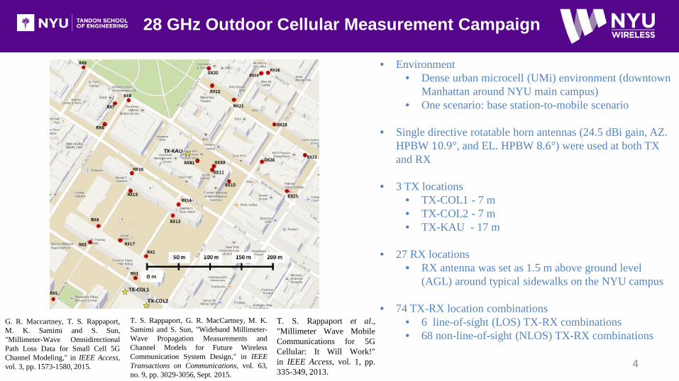
• Environment• Dense urban microcell (UMi) environment (downtown
Manhattan around NYU main campus)• One scenario: base station-to-mobile scenario
• Single directive rotatable horn antennas (24.5 dBi gain, AZ. HPBW 10.9°, and EL. HPBW 8.6°) were used at both TX and RX
• 3 TX locations• TX-COL1 - 7 m• TX-COL2 - 7 m• TX-KAU - 17 m
• 27 RX locations• RX antenna was set as 1.5 m above ground level
(AGL) around typical sidewalks on the NYU campus
• 74 TX-RX location combinations• 6 line-of-sight (LOS) TX-RX combinations• 68 non-line-of-sight (NLOS) TX-RX combinations
T. S. Rappaport, G. R. MacCartney, M. K.Samimi and S. Sun, "Wideband Millimeter-Wave Propagation Measurements andChannel Models for Future WirelessCommunication System Design," in IEEETransactions on Communications, vol. 63,no. 9, pp. 3029-3056, Sept. 2015.
T. S. Rappaport et al.,"Millimeter Wave MobileCommunications for 5GCellular: It Will Work!"in IEEE Access, vol. 1, pp.335-349, 2013.
4

73 GHz Outdoor Cellular Measurement Campaign
G. R. MacCartney and T. S. Rappaport,"73 GHz millimeter wave propagationmeasurements for outdoor urban mobileand backhaul communications in NewYork City," 2014 IEEE InternationalConference on Communications (ICC),Sydney, NSW, 2014, pp. 4862-4867.
• Environment• Dense urban microcell (UMi) environment (downtown Manhattan
around NYU main campus)• Two scenarios: base station-to-mobile and base station-to-backhaul
scenarios
• Single directive rotatable horn antennas (27 dBi gain, AZ. HPBW 7°, and EL. HPBW 7°) were used at both TX and RX
• 5 TX locations• TX-COL1 - 7 m• TX-COL2 - 7 m• TX-KAU - 17 m• TX-KIM1 - 7 m• TX-KIM2 - 7 m
• 27 RX locations• Base station-to-mobile scenario: RX antenna set as 2.00 m AGL• Base station-to-backhaul scenario: RX antenna set as 4.06 m AGL
• 74 TX-RX location combinations• 36 for mobile scenario with 5 LOS and 31 NLOS location
combinations • 38 for backhaul scenario with 4 LOS and 34 NLOS location
combinations
S. Sun, G. R. MacCartney, M. K. Samimi,S. Nie and T. S. Rappaport, "Millimeterwave multi-beam antenna combining for5G cellular link improvement in New YorkCity," 2014 IEEE International Conferenceon Communications (ICC), Sydney, NSW,2014, pp. 5468-5473.
5
38 GHz Outdoor Cellular Measurement Campaign
Base Station-to-Mobile Scenario
T. S. Rappaport, et al., "Broadband Millimeter-Wave Propagation Measurements and ModelsUsing Adaptive-Beam Antennas for OutdoorUrban Cellular Communications," in IEEETransactions on Antennas and Propagation,vol. 61, no. 4, pp. 1850-1859, April 2013.
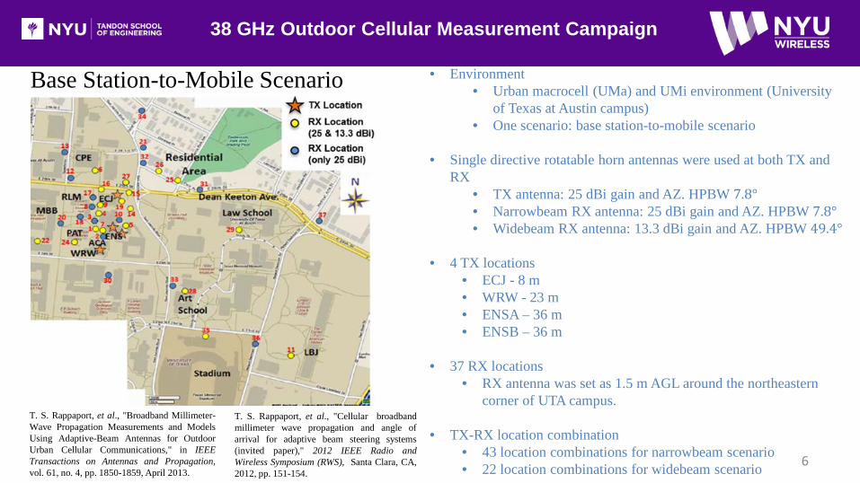
• Environment• Urban macrocell (UMa) and UMi environment (University
of Texas at Austin campus)• One scenario: base station-to-mobile scenario
• Single directive rotatable horn antennas were used at both TX and RX
• TX antenna: 25 dBi gain and AZ. HPBW 7.8°• Narrowbeam RX antenna: 25 dBi gain and AZ. HPBW 7.8°• Widebeam RX antenna: 13.3 dBi gain and AZ. HPBW 49.4°
• 4 TX locations• ECJ - 8 m• WRW - 23 m• ENSA – 36 m• ENSB – 36 m
• 37 RX locations• RX antenna was set as 1.5 m AGL around the northeastern
corner of UTA campus.
• TX-RX location combination• 43 location combinations for narrowbeam scenario• 22 location combinations for widebeam scenario
T. S. Rappaport, et al., "Cellular broadbandmillimeter wave propagation and angle ofarrival for adaptive beam steering systems(invited paper)," 2012 IEEE Radio andWireless Symposium (RWS), Santa Clara, CA,2012, pp. 151-154.
6
Peer-to-Peer Scenario
38 GHz Outdoor P2P Measurement Campaign
T. S. Rappaport, E. Ben-Dor, J. N. Murdock and Y.Qiao, "38 GHz and 60 GHz angle-dependentpropagation for cellular & peer-to-peer wirelesscommunications," 2012 IEEE International Conferenceon Communications (ICC), Ottawa, ON, 2012, pp.4568-4573.
E. Ben-Dor, T. S. Rappaport, Y. Qiao and S. J. Lauffenburger, "Millimeter-Wave 60 GHz Outdoor and Vehicle AOA Propagation Measurements Using aBroadband Channel Sounder," 2011 IEEE Global TelecommunicationsConference (GLOBECOM 2011), Houston, TX, USA, 2011, pp. 1-6.
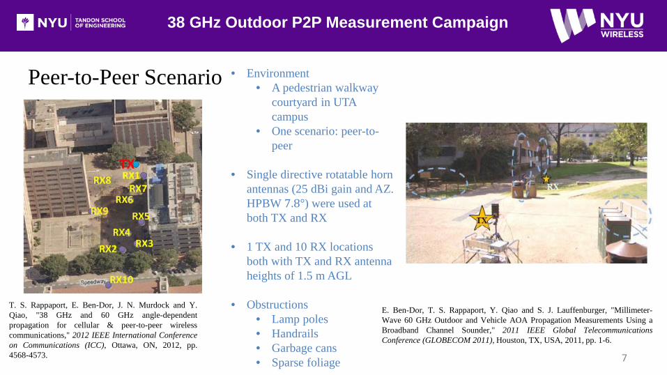
• Environment• A pedestrian walkway
courtyard in UTA campus
• One scenario: peer-to-peer
• Single directive rotatable horn antennas (25 dBi gain and AZ. HPBW 7.8°) were used at both TX and RX
• 1 TX and 10 RX locations both with TX and RX antenna heights of 1.5 m AGL
• Obstructions• Lamp poles• Handrails• Garbage cans• Sparse foliage 7
60 GHz Outdoor P2P and Vehicular Measurement Campaign
Peer-to-Peer Scenario• The 60 GHz P2P measurements consisted of the same environment and TX and RX locations as in
38 GHz outdoor P2P measurement campaign
Vehicular scenario
E. Ben-Dor, T. S. Rappaport, Y. Qiao and S. J. Lauffenburger, "Millimeter-Wave 60 GHzOutdoor and Vehicle AOA Propagation Measurements Using a Broadband ChannelSounder," 2011 IEEE Global Telecommunications Conference (GLOBECOM 2011),Houston, TX, USA, 2011, pp. 1-6.
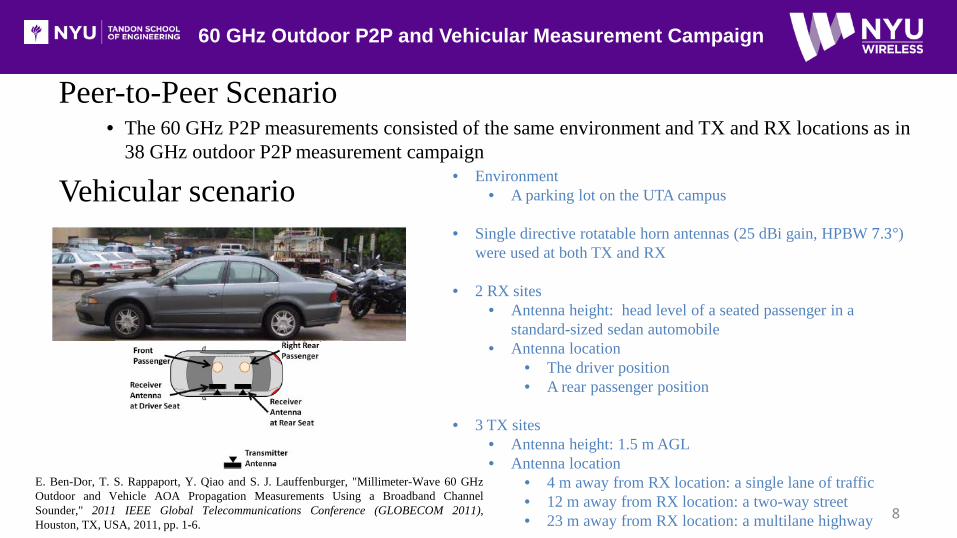
• Environment• A parking lot on the UTA campus
• Single directive rotatable horn antennas (25 dBi gain, HPBW 7.3°) were used at both TX and RX
• 2 RX sites• Antenna height: head level of a seated passenger in a
standard-sized sedan automobile• Antenna location
• The driver position• A rear passenger position
• 3 TX sites• Antenna height: 1.5 m AGL• Antenna location
• 4 m away from RX location: a single lane of traffic• 12 m away from RX location: a two-way street• 23 m away from RX location: a multilane highway 8

28 GHz and 73 GHz Indoor Measurement Campaign
G. R. MacCartney, T. S. Rappaport, S. Sun and S. Deng, "IndoorOffice Wideband Millimeter-Wave Propagation Measurementsand Channel Models at 28 and 73 GHz for Ultra-Dense 5GWireless Networks," in IEEE Access, vol. 3, pp. 2388-2424,2015.
Environment: A typical single-floor office environment (9th floor of 2 MetroTechCenter in downtown Brooklyn, New York)
• Environment scenarios• Corridor environment• Open-plan environment• Closed-plan environment
• Single directive rotatable horn antennas were used at both TX and RX
• 28 GHz: 15 dBi gain, AZ. HPBW 28.8° and EL. HPBW 30°
• 73 GHz: 20 dBi gain, AZ. HPBW 15° and EL. HPBW 15°
• 5 TX locations• TX antenna was set as 2.5 m AGL
• 33 RX locations• RX antenna was set as 1.5 m AGL
• 48 TX-RX location combinations• 10 LOS combinations• 38 NLOS combinationsS. Deng, M. K. Samimi and T. S. Rappaport, "28 GHz
and 73 GHz millimeter-wave indoor propagationmeasurements and path loss models," 2015 IEEEInternational Conference on Communication Workshop(ICCW), London, 2015, pp. 1244-1250.
9
Acknowledgment
Acknowledgement to our NYU WIRELESS Industrial Affiliates and NSF
Grants: 1320472, 1302336, and 1555332 10
11
1. G. R. MacCartney, T. S. Rappaport, M. K. Samimi and S. Sun, "Millimeter-Wave Omnidirectional Path Loss Data for Small Cell 5GChannel Modeling," in IEEE Access, vol. 3, pp. 1573-1580, 2015.
2. G. R. MacCartney, T. S. Rappaport, S. Sun and S. Deng, "Indoor Office Wideband Millimeter-Wave Propagation Measurements andChannel Models at 28 and 73 GHz for Ultra-Dense 5G Wireless Networks," in IEEE Access, vol. 3, pp. 2388-2424, 2015.
3. G. R. MacCartney and T. S. Rappaport, "73 GHz millimeter wave propagation measurements for outdoor urban mobile and backhaulcommunications in New York City," 2014 IEEE International Conference on Communications (ICC), Sydney, NSW, 2014, pp. 4862-4867.
4. T. S. Rappaport, G. R. MacCartney, M. K. Samimi and S. Sun, "Wideband Millimeter-Wave Propagation Measurements and ChannelModels for Future Wireless Communication System Design," in IEEE Transactions on Communications, vol. 63, no. 9, pp. 3029-3056,Sept. 2015.
5. T. S. Rappaport, F. Gutierrez, E. Ben-Dor, J. N. Murdock, Y. Qiao and J. I. Tamir, "Broadband Millimeter-Wave PropagationMeasurements and Models Using Adaptive-Beam Antennas for Outdoor Urban Cellular Communications," in IEEE Transactions onAntennas and Propagation, vol. 61, no. 4, pp. 1850-1859, April 2013.
6. T. S. Rappaport, E. Ben-Dor, J. N. Murdock and Y. Qiao, "38 GHz and 60 GHz angle-dependent propagation for cellular & peer-to-peerwireless communications," 2012 IEEE International Conference on Communications (ICC), Ottawa, ON, 2012, pp. 4568-4573.
7. E. Ben-Dor, T. S. Rappaport, Y. Qiao and S. J. Lauffenburger, "Millimeter-Wave 60 GHz Outdoor and Vehicle AOA PropagationMeasurements Using a Broadband Channel Sounder," Global Telecommunications Conference (GLOBECOM 2011), 2011 IEEE,Houston, TX, USA, 2011, pp. 1-6.
8. https://en.wikipedia.org/wiki/Elmer_Holmes_Bobst_Library9. S. Y. Seidel and T. S. Rappaport, "Path loss prediction in multifloored buildings at 914 MHz," in Electronics Letters, vol. 27, no. 15, pp.
1384-1387, 18 July 1991.
References
12
10. S. Y. Seidel and T. S. Rappaport, "914 MHz path loss prediction models for indoor wireless communications in multifloored buildings,"in IEEE Transactions on Antennas and Propagation, vol. 40, no. 2, pp. 207-217, Feb 1992.
11. T. S. Rappaport et al., "Millimeter Wave Mobile Communications for 5G Cellular: It Will Work!" in IEEE Access, vol. 1, pp. 335-349,2013.
12. Y. Azar et al., "28 GHz propagation measurements for outdoor cellular communications using steerable beam antennas in New Yorkcity," 2013 IEEE International Conference on Communications (ICC), Budapest, 2013, pp. 5143-5147.
13. G. R. MacCartney, J. Zhang, S. Nie and T. S. Rappaport, "Path loss models for 5G millimeter wave propagation channels in urbanmicrocells," 2013 IEEE Global Communications Conference (GLOBECOM), Atlanta, GA, 2013, pp. 3948-3953.
14. T. S. Rappaport, Y. Qiao, J. I. Tamir, J. N. Murdock and E. Ben-Dor, "Cellular broadband millimeter wave propagation and angle ofarrival for adaptive beam steering systems (invited paper)," 2012 IEEE Radio and Wireless Symposium (RWS), Santa Clara, CA, 2012,pp. 151-154.
15. M. R. Akdeniz et al., "Millimeter Wave Channel Modeling and Cellular Capacity Evaluation," in IEEE Journal on Selected Areas inCommunications, vol. 32, no. 6, pp. 1164-1179, June 2014.
16. S. Sun, G. R. MacCartney, M. K. Samimi, S. Nie and T. S. Rappaport, "Millimeter multi-beam antenna combining for 5G cellular linkimprovement in New York City," 2014 IEEE International Conference on Communications (ICC), Sydney, NSW, 2014, pp. 5468-5473.
17. F. Gutierrez Jr., T. S. Rappaport and J. Murdock, "Millimeter-Wave CMOS Antennas and RFIC Parameter Extraction for VehicularApplications," in Proc. IEEE 72nd VTC Fall, Sep. 2010, pp. 1-6.
18. M. Samimi et al., "28 GHz Angle of Arrival and Angle of Departure Analysis for Outdoor Cellular Communications Using SteerableBeam Antennas in New York City," in Proc. IEEE 77th VTC-Spring, Jun. 2013, pp. 1-6.
19. S. Sun and T. S. Rappaport, "Multi-beam antenna combining for 28 GHz cellular link improvement in urban environments," 2013 IEEEGlobal Communications Conference (GLOBECOM), Atlanta, GA, 2013, pp. 3754-3759.
References

13
20. S. Nie, G. R. MacCartney, S. Sun and T. S. Rappaport, "72 GHz millimeter wave indoor measurements for wireless and backhaulcommunications," 2013 IEEE 24th Annual International Symposium on Personal, Indoor, and Mobile Radio Communications(PIMRC), London, 2013, pp. 2429-2433.
21. S. Deng, M. K. Samimi and T. S. Rappaport, "28 GHz and 73 GHz millimeter-wave indoor propagation measurements and path lossmodels," 2015 IEEE International Conference on Communication Workshop (ICCW), London, 2015, pp. 1244-1250.
22. T. S. Rappaport, Wireless communications: principles and practice. 2nd ed. Upper Saddle River, NJ, UAS: Prentice-Hall, 2002.23. D. Cox, "Delay Doppler characteristics of multipath propagation at 910 MHz in a suburban mobile radio environment," in IEEE
Transactions on Antennas and Propagation, vol. 20, no. 5, pp. 625-635, Sep 1972.24. G. Martin, "Wideband channel sounding dynamic range using a sliding correlator," in Proc. IEEE 51st VTC-Spring, Tokyo, Japan,
2000, vol. 3, pp. 2517-2521.25. R. J. Pirkl and G. D. Durgin, "Optimal Sliding Correlator Channel Sounder Design," in IEEE Transactions on Wireless
Communications, vol. 7, no. 9, pp. 3488-3497, September 2008.26. A. Ghosh et al., "Millimeter-Wave Enhanced Local Area Systems: A High-Data-Rate Approach for Future Wireless Networks," in
IEEE Journal on Selected Areas in Communications, vol. 32, no. 6, pp. 1152-1163, June 2014.27. T. S. Rappaport, R. W. Heath, Jr., R. C. Daniels, and J. N. Murdock, Millimeter wave wireless communications. Englewood Cliffs,
NJ, USA: Prentice Hall, 2015.28. T. S. Rappaport, S. DiPierro and R. Akturan, "Analysis and Simulation of Interference to Vehicle-Equipped Digital Receivers From
Cellular Mobile Terminals Operating in Adjacent Frequencies," in IEEE Transactions on Vehicular Technology, vol. 60, no. 4, pp.1664-1676, May 2011.
29. W. H. Kummer and E. S. Gillespie. "Antenna measurements 1978." IEEE Proceedings. Vol. 66. 1978.30. S. Sun et al., "Investigation of Prediction Accuracy, Sensitivity, and Parameter Stability of Large-Scale Propagation Path Loss Models
for 5G Wireless Communications," in IEEE Transactions on Vehicular Technology, vol. 65, no. 5, pp. 2843-2860, May 2016.
References

14
31. G. R. MacCartney, M. K. Samimi and T. S. Rappaport, "Exploiting directionality for millimeter-wave wireless system improvement,"2015 IEEE International Conference on Communications (ICC), London, 2015, pp. 2416-2422.
32. M. K. Samimi, “Characterization of the 28 GHz Millimeter-Wave Dense Urban Channel for Future 5G Mobile,” Master of ScienceDissertation, May 2014.
33. H. Zhao et al., "28 GHz millimeter wave cellular communication measurements for reflection and penetration loss in and aroundbuildings in New York city," 2013 IEEE International Conference on Communications (ICC), Budapest, 2013, pp. 5163-5167.
34. M. K. Samimi and T. S. Rappaport, "3-D Millimeter-Wave Statistical Channel Model for 5G Wireless System Design," in IEEETransactions on Microwave Theory and Techniques, vol. 64, no. 7, pp. 2207-2225, July 2016.
35. S. Y. Seidel and T. S. Rappaport, "Site-specific propagation prediction for wireless in-building personal communication system design,"in IEEE Transactions on Vehicular Technology, vol. 43, no. 4, pp. 879-891, Nov 1994.
36. G. Durgin, N. Patwari and T. S. Rappaport, "An advanced 3D ray launching method for wireless propagation prediction," VehicularTechnology Conference, 1997, IEEE 47th, Phoenix, AZ, 1997, pp. 785-789 vol.2.
37. S. Y. Seidel and T. S. Rappaport, "A ray tracing technique to predict path loss and delay spread inside buildings," 1992 IEEE GlobalTelecommunications Conference, Orlando, FL, 1992, pp. 649-653 vol.2.
38. K. R. Schaubach, N. J. Davis and T. S. Rappaport, "A ray tracing method for predicting path loss and delay spread in microcellularenvironments," Vehicular Technology Conference, 1992, IEEE 42nd, Denver, CO, 1992, pp. 932-935 vol.2.
39. C. M. P. Ho and T. S. Rappaport, "Wireless channel prediction in a modern office building using an image-based ray tracing method,"1993 IEEE Global Telecommunications Conference, Houston, TX, 1993, pp. 1247-1251 vol.2.
40. T. S. Rappaport and V. Fung, "Simulation of bit error performance of FSK, BPSK, and π/4 DQPSK in flat fading indoor radio channelsusing a measurement-based channel model," in IEEE Transactions on Vehicular Technology, vol. 40, no. 4, pp. 731-740, Nov 1991.
References

15
References41. V. Fung, T. S. Rappaport and B. Thoma, "Bit error simulation for π/4 DQPSK mobile radio communications using two-ray and
measurement-based impulse response models," in IEEE Journal on Selected Areas in Communications, vol. 11, no. 3, pp. 393-405,Apr 1993.
42. V. Fung and T. S. Rappaport, "Bit-error simulation of π/4 DQPSK in flat and frequency-selective fading mobile radio channels withreal time applications," 1991 IEEE International Conference on Communications, Denver, pp. 553-557 vol.2.
43. T. S. Rappaport, “Keynote Speech: Millimeter Wave Wireless Communications-The Renaissance of Computing andCommunications,” presented at the IEEE International Conference on Communications (ICC), Sydney, Australia, Jun. 2014, slidesavailable at ICC 14 website.
44. “VNI mobile forecast highlights, 2014–2019,” CISCO, San Jose, CA, USA, 2015. Available: http://www.cisco.com/assets/sol/sp/vni/forecast_highlights_mobil/index.html
45. “Cisco visual networking index: Mobile data traffic forecast update, 2013–2018,” CISCO, San Jose, CA, USA, Feb. 2014. [Online]. Available:http://www.cisco.com/c/en /us/solutions /collateral/service-provider/ visual-networking-index-vni/white_paper_c11-520862.pdf
46. J. N. Murdock, E. Ben-Dor, Y. Qiao, J. I. Tamir and T. S. Rappaport, "A 38 GHz cellular outage study for an urban outdoor campusenvironment," 2012 IEEE Wireless Communications and Networking Conference (WCNC), Shanghai, 2012, pp. 3085-3090.
47. T. S. Rappaport, Y. Qiao, J. I. Tamir, J. N. Murdock and E. Ben-Dor, "Cellular broadband millimeter wave propagation and angle ofarrival for adaptive beam steering systems (invited paper),"Radio and Wireless Symposium (RWS), 2012 IEEE, Santa Clara, CA,2012, pp. 151-154.
48. G. Durgin, N. Patwari and T. S. Rappaport, "Improved 3D ray launching method for wireless propagation prediction," inElectronics Letters, vol. 33, no. 16, pp. 1412-1413, 31 Jul 1997.
49. K. K. Bae et al., "WCDMA STTD performance analysis with transmitter location optimization in indoor systems using ray-tracingtechnique," Radio and Wireless Conference, 2002. RAWCON 2002. IEEE, 2002, pp. 123-127.
16
50. T. T. Tran and T. S. Rappaport, "Site specific propagation prediction models for PCS design and installation," 1992 IEEE MilitaryCommunications Conference, San Diego, CA, 1992, pp. 1062-1065 vol.3.
51. S. Seidel, K. Schaubach, T. Tran and T. Rappaport, "Research in site-specific propagation modeling for PCS system design," VehicularTechnology Conference, 1993., 43rd IEEE, Secaucus, NJ, 1993, pp. 261-264.
References

Thank you!
17