nysapls 50th anniversary surveyor's conference and …c.ymcdn.com/sites/ · nysapls 50th...
TRANSCRIPT
NYSAPLS 50th Anniversary Surveyor's Conference and Exhibition
© 2008 Bentley Systems, Incorporated
Field to Finish - 3D Modeling and DTM (InRoads Survey and PowerSurvey Basics)
Presenter: Gerald B. Danzy, Software/Product Consultant
Bentley Systems, Incorporated 685 Stockton Drive Exton, PA 19341 www.bentley.com

NYSAPLS 50 th Anniversary Surveyor's Conference and Exhibition
© 2008 Bentley Systems, Incorporated 2
FIELD TO FINISH – 3D MODELING AND DTM

NYSAPLS 50 th Anniversary Surveyor's Conference and Exhibition
© 2008 Bentley Systems, Incorporated 3
FIELD TO FINISH – 3D MODELING AND DTM
INTRODUCTION This is a workshop to learn the basics of InRoads Survey/PowerSurvey. After this workshop you will know how survey collected in the field turns into data you can use with InRoads. This will give you an introduction on how to use InRoads Survey. You will learn how to reduce raw survey data then review the Survey Styles and Fieldbook. After creating the Fieldbook we will then generate the deliverables needed from survey data: Geometry (alg), Surface (dtm), Design files (dgn) and Drainage files (sdb).
In this workshop, the topics covered include
Reducing Survey Data
Fieldbook
Style Manager
Fix Errors in Fieldbook
Survey Deliverables
Geometry
Surfaces
Design File
Drainage File

NYSAPLS 50 th Anniversary Surveyor's Conference and Exhibition
© 2008 Bentley Systems, Incorporated 4
FIELD TO FINISH – 3D MODELING AND DTM
LESSON NAME: REDUCING SURVEY DATA
LESSON OBJECTIVE: In this Lesson you will learn how to Import Survey data and properly prepare the data for Deliverables.
> EXERCISE: IMPORTING SURVEY DATA
Starting InRoads Survey (PowerSurvey) and Importing Data
1. First we will start MicroStation and InRoads Survey or PowerSurvey. 2. When the MicroStation Manager appears, open the file topo.dgn.
3. When MicroStation and InRoads Survey starts open the Project Defaults (File >
Project Defaults).
4. Close the Project Defaults dialog.

NYSAPLS 50 th Anniversary Surveyor's Conference and Exhibition
© 2008 Bentley Systems, Incorporated 5
FIELD TO FINISH – 3D MODELING AND DTM
5. Import the file Survey.sdr (On the InRoads Menu: File > Import > Survey Data (File Type: Sokkia SDR.sdr)).
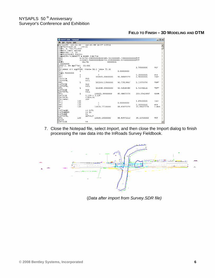
6. Highlight the file Survey.SDR and right click. Then open with NotePad to review
the raw data file.
NYSAPLS 50 th Anniversary Surveyor's Conference and Exhibition
© 2008 Bentley Systems, Incorporated 6
FIELD TO FINISH – 3D MODELING AND DTM
7. Close the Notepad file, select Import, and then close the Import dialog to finish
processing the raw data into the InRoads Survey Fieldbook.
(Data after import from Survey.SDR file)
NYSAPLS 50 th Anniversary Surveyor's Conference and Exhibition
© 2008 Bentley Systems, Incorporated 7
FIELD TO FINISH – 3D MODELING AND DTM
> EXERCISE: FIELDBOOK NAVIGATION
Understanding and navigating in the Fieldbook
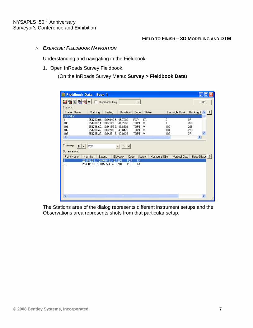
1. Open InRoads Survey Fieldbook. (On the InRoads Survey Menu: Survey > Fieldbook Data)
The Stations area of the dialog represents different instrument setups and the Observations area represents shots from that particular setup.
NYSAPLS 50 th Anniversary Surveyor's Conference and Exhibition
© 2008 Bentley Systems, Incorporated 8
FIELD TO FINISH – 3D MODELING AND DTM
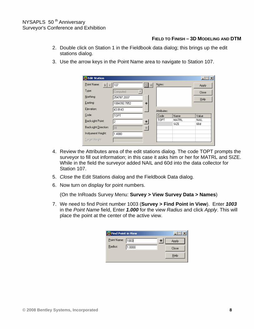
2. Double click on Station 1 in the Fieldbook data dialog; this brings up the edit stations dialog.
3. Use the arrow keys in the Point Name area to navigate to Station 107.
4. Review the Attributes area of the edit stations dialog. The code TOPT prompts the
surveyor to fill out information; in this case it asks him or her for MATRL and SIZE. While in the field the surveyor added NAIL and 60d into the data collector for Station 107.
5. Close the Edit Stations dialog and the Fieldbook Data dialog. 6. Now turn on display for point numbers.
(On the InRoads Survey Menu: Survey > View Survey Data > Names)
7. We need to find Point number 1003 (Survey > Find Point in View). Enter 1003 in the Point Name field, Enter 1.000 for the view Radius and click Apply. This will place the point at the center of the active view.

NYSAPLS 50 th Anniversary Surveyor's Conference and Exhibition
© 2008 Bentley Systems, Incorporated 9
FIELD TO FINISH – 3D MODELING AND DTM
8. Open the InRoads Survey Fieldbook (Survey > Fieldbook Data). In the Observation area, pick that target button on the right and select point 1003 (in the graphics) that you zoomed into in the previous steps.
9. Double click on Point 1003 in the Observation area of the dialog.
NYSAPLS 50 th Anniversary Surveyor's Conference and Exhibition
© 2008 Bentley Systems, Incorporated 10
FIELD TO FINISH – 3D MODELING AND DTM
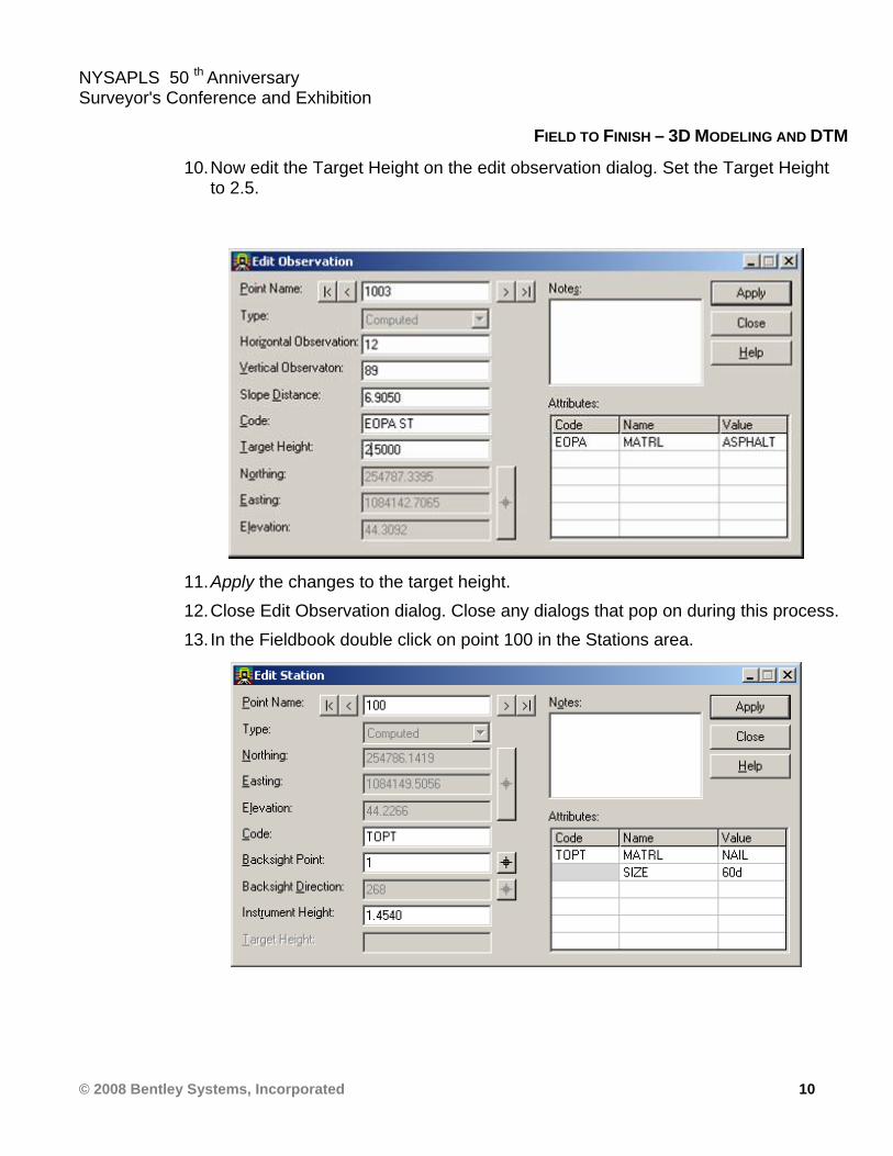
10. Now edit the Target Height on the edit observation dialog. Set the Target Height to 2.5.
11. Apply the changes to the target height. 12. Close Edit Observation dialog. Close any dialogs that pop on during this process. 13. In the Fieldbook double click on point 100 in the Stations area.
NYSAPLS 50 th Anniversary Surveyor's Conference and Exhibition
© 2008 Bentley Systems, Incorporated 11
FIELD TO FINISH – 3D MODELING AND DTM
14. This will allow you to edit the Instrument Height and the corresponding station’s elevation would be updated automatically due to the instrument height change.
15. Do not make any instrument height changes. Close the Edit Station and the Fieldbook dialog boxes.
> EXERCISE: STYLE MANAGER
Filtering and Editing the Style Manager
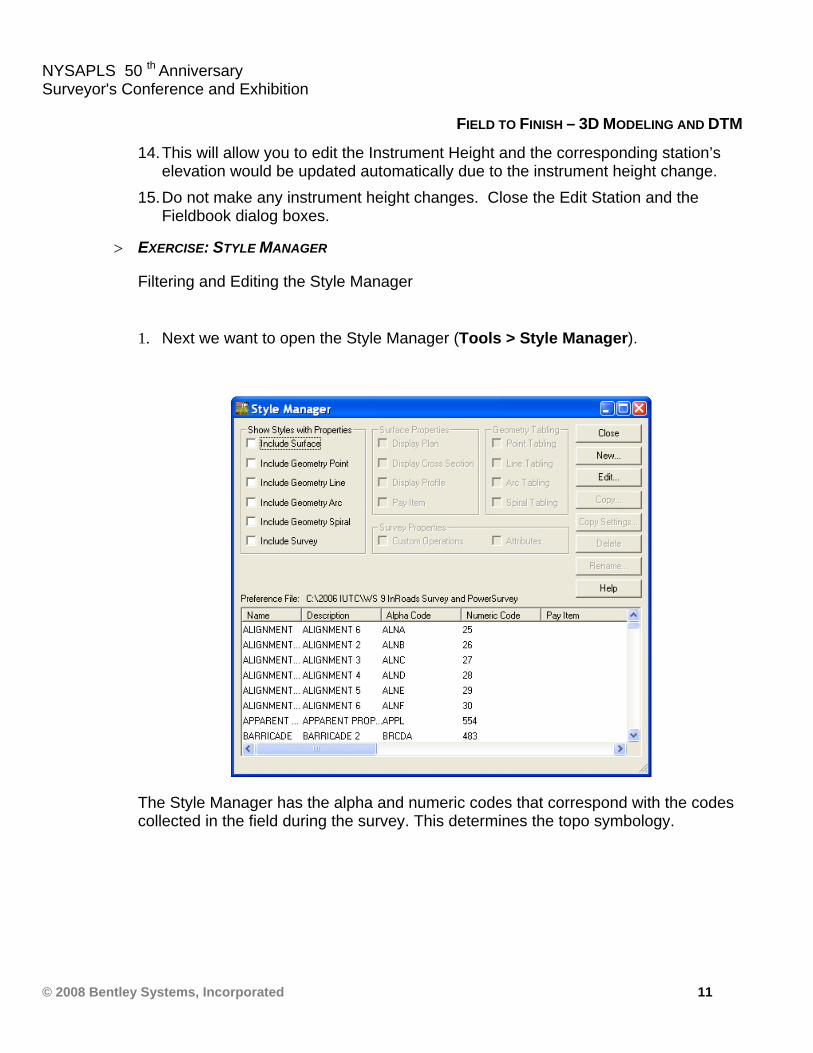
1. Next we want to open the Style Manager (Tools > Style Manager).
The Style Manager has the alpha and numeric codes that correspond with the codes collected in the field during the survey. This determines the topo symbology.

NYSAPLS 50 th Anniversary Surveyor's Conference and Exhibition
© 2008 Bentley Systems, Incorporated 12
FIELD TO FINISH – 3D MODELING AND DTM
2. Next toggle the Include Survey toggle. This will filter the Style Manager so you only see the features that are associated with survey data.
3. Highlight the Style Name with the Description DITCH BACKSLOPE 2 and double click to open the Edit Style dialog.
Hint The headers of the columns in the dialog are resizable
NYSAPLS 50 th Anniversary Surveyor's Conference and Exhibition
© 2008 Bentley Systems, Incorporated 13
FIELD TO FINISH – 3D MODELING AND DTM
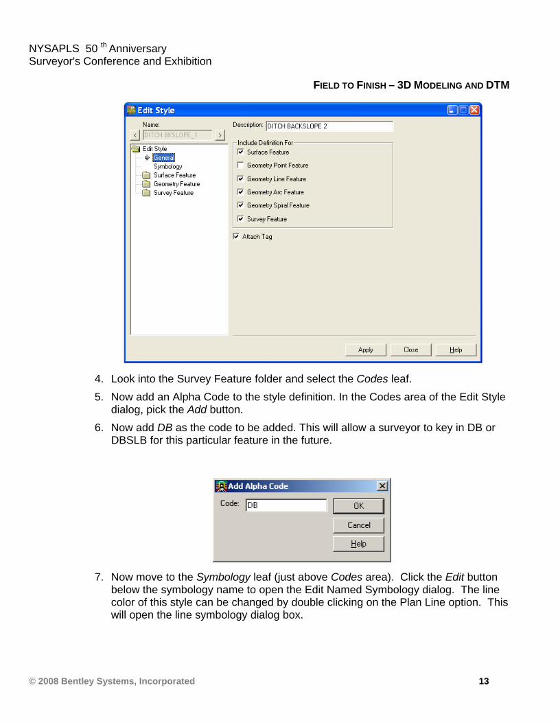
4. Look into the Survey Feature folder and select the Codes leaf. 5. Now add an Alpha Code to the style definition. In the Codes area of the Edit Style
dialog, pick the Add button. 6. Now add DB as the code to be added. This will allow a surveyor to key in DB or
DBSLB for this particular feature in the future.
7. Now move to the Symbology leaf (just above Codes area). Click the Edit button below the symbology name to open the Edit Named Symbology dialog. The line color of this style can be changed by double clicking on the Plan Line option. This will open the line symbology dialog box.
NYSAPLS 50 th Anniversary Surveyor's Conference and Exhibition
© 2008 Bentley Systems, Incorporated 14
FIELD TO FINISH – 3D MODELING AND DTM
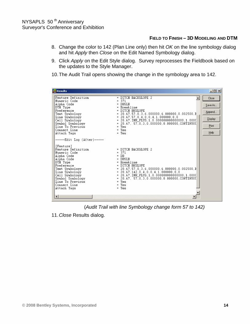
8. Change the color to 142 (Plan Line only) then hit OK on the line symbology dialog and hit Apply then Close on the Edit Named Symbology dialog.
9. Click Apply on the Edit Style dialog. Survey reprocesses the Fieldbook based on the updates to the Style Manager.
10. The Audit Trail opens showing the change in the symbology area to 142.
(Audit Trail with line Symbology change form 57 to 142)
11. Close Results dialog.
NYSAPLS 50 th Anniversary Surveyor's Conference and Exhibition
© 2008 Bentley Systems, Incorporated 15
FIELD TO FINISH – 3D MODELING AND DTM
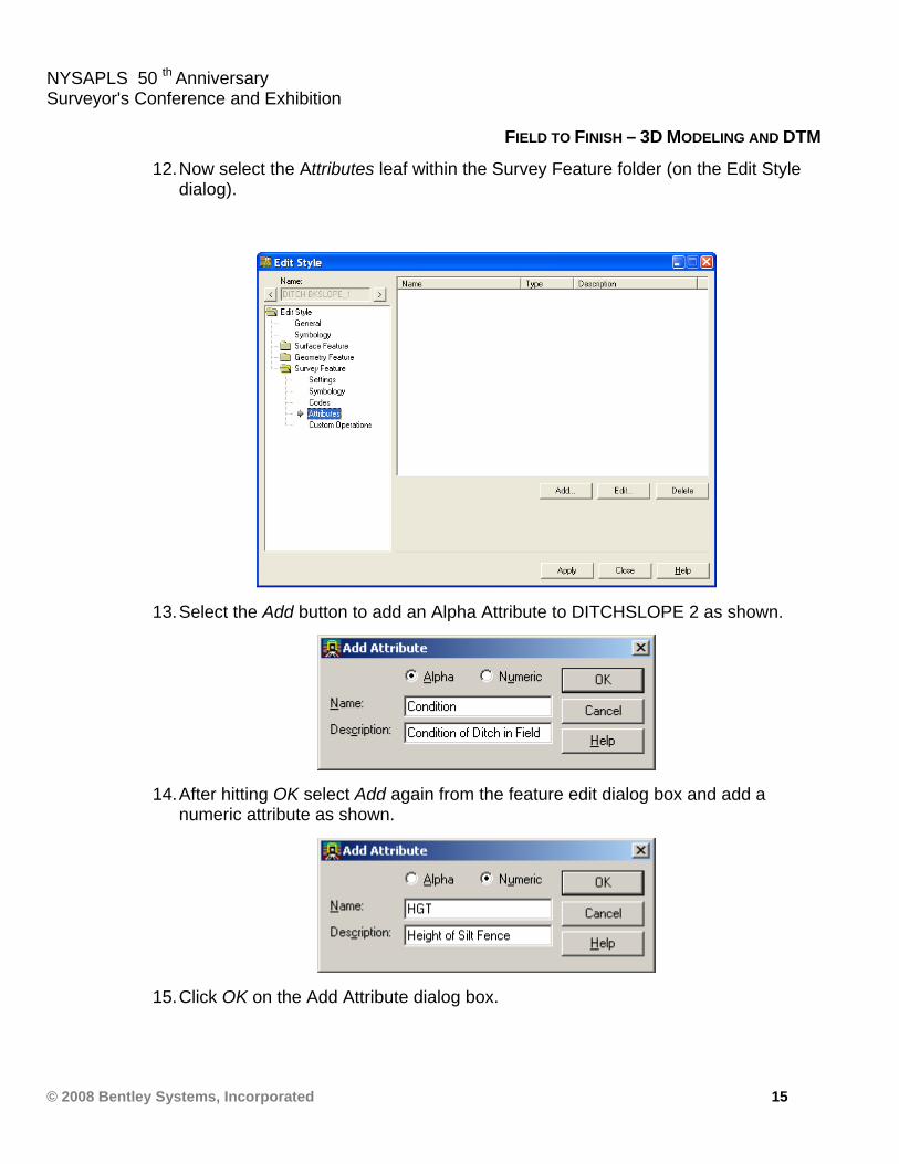
12. Now select the Attributes leaf within the Survey Feature folder (on the Edit Style dialog).
13. Select the Add button to add an Alpha Attribute to DITCHSLOPE 2 as shown.
14. After hitting OK select Add again from the feature edit dialog box and add a numeric attribute as shown.
15. Click OK on the Add Attribute dialog box.

NYSAPLS 50 th Anniversary Surveyor's Conference and Exhibition
© 2008 Bentley Systems, Incorporated 16
FIELD TO FINISH – 3D MODELING AND DTM
16. Select Apply on the Edit Style dialog and then Close. Close the audit trail dialog as well. You should now be back to the Style Manager dialog.
17. Select the style with description DICTH CENTERLINE 1 and double click to edit. 18. Select the Custom Operations leaf from the Survey Feature folder. Highlight and
copy the information in this dialog (right click and select Copy).
19. Close dialog box (select No if a Save warning pops up). 20. On the Style Manager dialog double click on style that has the description of
DITCH BACKSLOPE 2. 21. Go to the Custom Operations leaf within the Survey Feature folder.

NYSAPLS 50 th Anniversary Surveyor's Conference and Exhibition
© 2008 Bentley Systems, Incorporated 17
FIELD TO FINISH – 3D MODELING AND DTM
22. Right click and paste the information copied from the DITCH CENTERLINE 1 style. Edit the bottom to match the dialog below. You have now created a custom operation for DITCH BACKSLOPE 2.
23. Select Apply and then Close on Edit Style dialog, dismiss the Audit trail, and
select Close on the Style Manager dialog.

NYSAPLS 50 th Anniversary Surveyor's Conference and Exhibition
© 2008 Bentley Systems, Incorporated 18
FIELD TO FINISH – 3D MODELING AND DTM
> EXERCISE: FIELDBOOK EDITING
Learn how to edit and manipulate the Fieldbook
1. Open InRoads Survey Fieldbook (Survey > Fieldbook Data).
2. In the Stations area highlight 100. 3. In the Observation area scroll down and highlight point 1028. 4. Look at the Chainage area. You should have DBSLB as the active chain. 5. Use the arrow buttons to move up and down the chain. This would allow you to
check ditch elevation in the Fieldbook and any point being associated to the chain.
6. Next we will review how control codes draw the ditch DBSLB in plan view.
NYSAPLS 50 th Anniversary Surveyor's Conference and Exhibition
© 2008 Bentley Systems, Incorporated 19
FIELD TO FINISH – 3D MODELING AND DTM
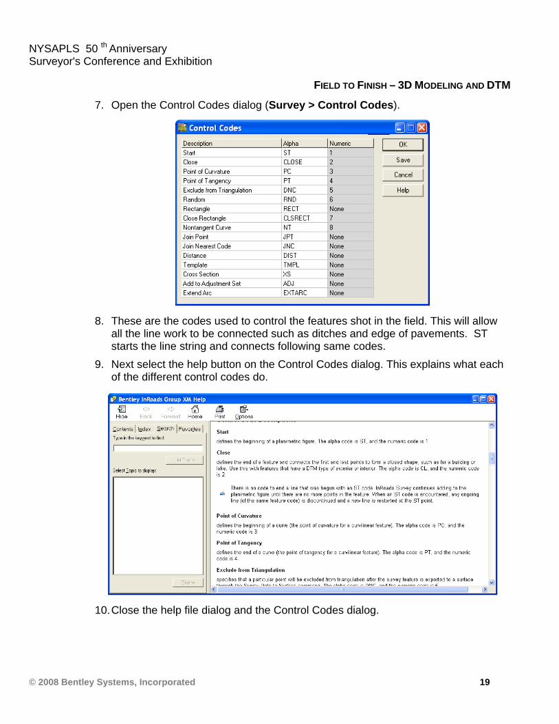
7. Open the Control Codes dialog (Survey > Control Codes).
8. These are the codes used to control the features shot in the field. This will allow
all the line work to be connected such as ditches and edge of pavements. ST starts the line string and connects following same codes.
9. Next select the help button on the Control Codes dialog. This explains what each of the different control codes do.
10. Close the help file dialog and the Control Codes dialog.
NYSAPLS 50 th Anniversary Surveyor's Conference and Exhibition
© 2008 Bentley Systems, Incorporated 20
FIELD TO FINISH – 3D MODELING AND DTM
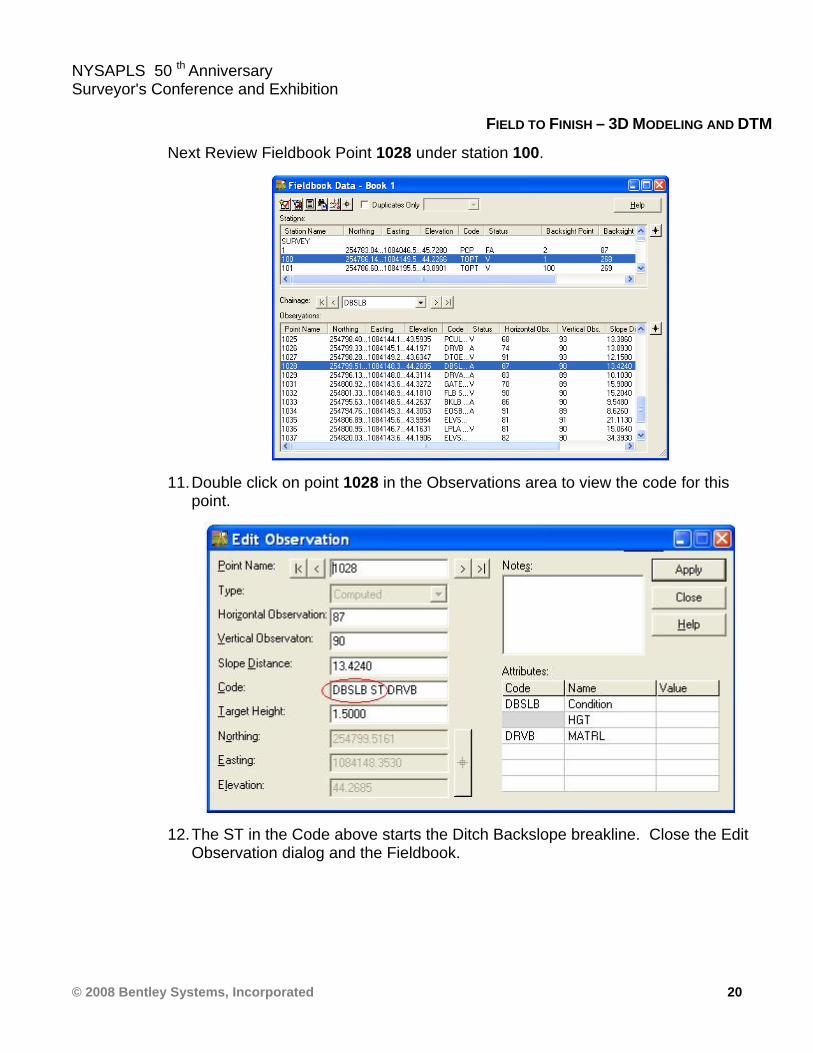
Next Review Fieldbook Point 1028 under station 100.
11. Double click on point 1028 in the Observations area to view the code for this point.
12. The ST in the Code above starts the Ditch Backslope breakline. Close the Edit Observation dialog and the Fieldbook.
NYSAPLS 50 th Anniversary Surveyor's Conference and Exhibition
© 2008 Bentley Systems, Incorporated 21
FIELD TO FINISH – 3D MODELING AND DTM
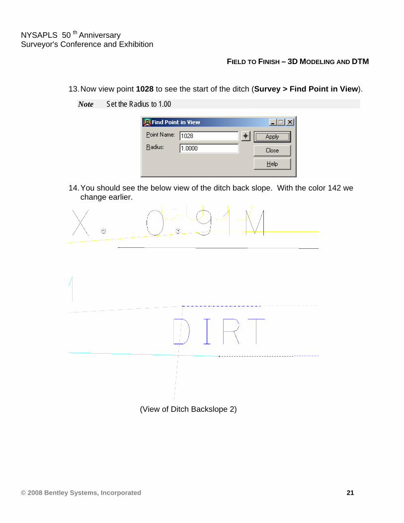
13. Now view point 1028 to see the start of the ditch (Survey > Find Point in View).
Note Set the Radius to 1.00
14. You should see the below view of the ditch back slope. With the color 142 we change earlier.
(View of Ditch Backslope 2)
NYSAPLS 50 th Anniversary Surveyor's Conference and Exhibition
© 2008 Bentley Systems, Incorporated 22
FIELD TO FINISH – 3D MODELING AND DTM
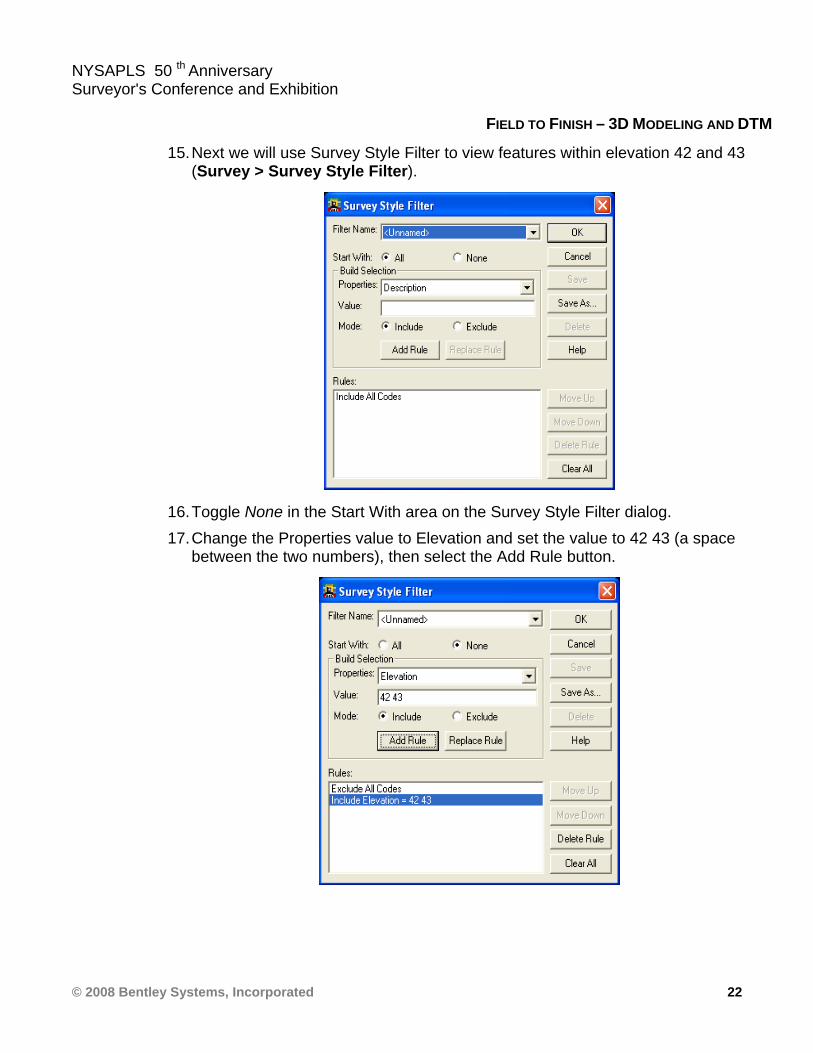
15. Next we will use Survey Style Filter to view features within elevation 42 and 43 (Survey > Survey Style Filter).
16. Toggle None in the Start With area on the Survey Style Filter dialog. 17. Change the Properties value to Elevation and set the value to 42 43 (a space
between the two numbers), then select the Add Rule button.
NYSAPLS 50 th Anniversary Surveyor's Conference and Exhibition
© 2008 Bentley Systems, Incorporated 23
FIELD TO FINISH – 3D MODELING AND DTM
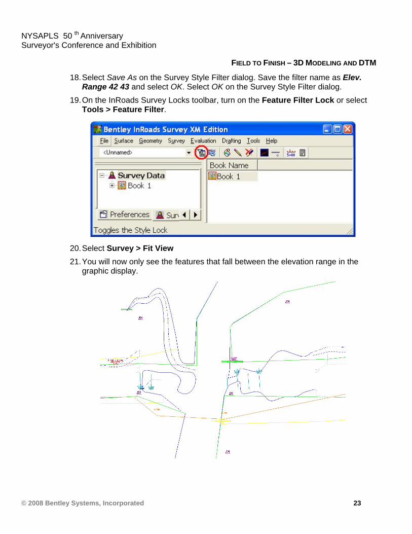
18. Select Save As on the Survey Style Filter dialog. Save the filter name as Elev. Range 42 43 and select OK. Select OK on the Survey Style Filter dialog.
19. On the InRoads Survey Locks toolbar, turn on the Feature Filter Lock or select Tools > Feature Filter.
20. Select Survey > Fit View 21. You will now only see the features that fall between the elevation range in the
graphic display.
NYSAPLS 50 th Anniversary Surveyor's Conference and Exhibition
© 2008 Bentley Systems, Incorporated 24
FIELD TO FINISH – 3D MODELING AND DTM
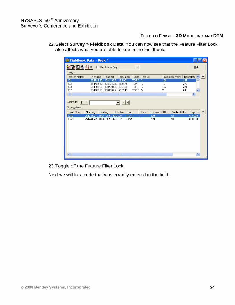
22. Select Survey > Fieldbook Data. You can now see that the Feature Filter Lock also affects what you are able to see in the Fieldbook.
23. Toggle off the Feature Filter Lock.
Next we will fix a code that was errantly entered in the field.
NYSAPLS 50 th Anniversary Surveyor's Conference and Exhibition
© 2008 Bentley Systems, Incorporated 25
FIELD TO FINISH – 3D MODELING AND DTM
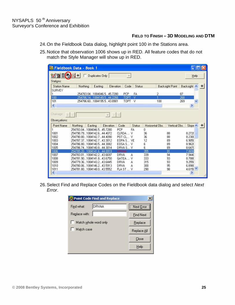
24. On the Fieldbook Data dialog, highlight point 100 in the Stations area. 25. Notice that observation 1006 shows up in RED. All feature codes that do not
match the Style Manager will show up in RED.
26. Select Find and Replace Codes on the Fieldbook data dialog and select Next Error.
NYSAPLS 50 th Anniversary Surveyor's Conference and Exhibition
© 2008 Bentley Systems, Incorporated 26
FIELD TO FINISH – 3D MODELING AND DTM
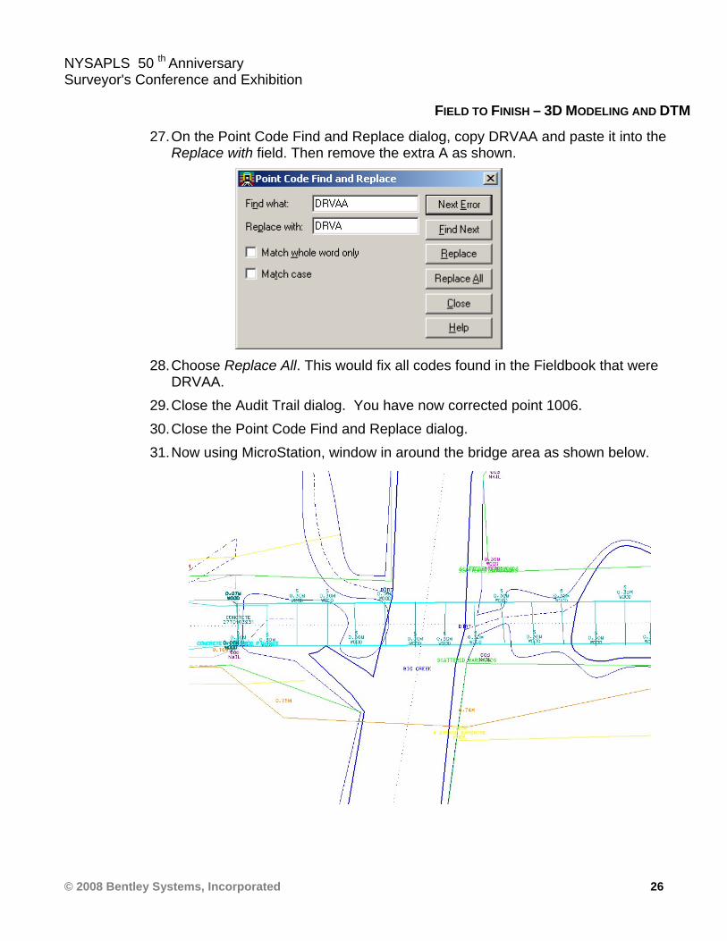
27. On the Point Code Find and Replace dialog, copy DRVAA and paste it into the Replace with field. Then remove the extra A as shown.
28. Choose Replace All. This would fix all codes found in the Fieldbook that were
DRVAA. 29. Close the Audit Trail dialog. You have now corrected point 1006. 30. Close the Point Code Find and Replace dialog. 31. Now using MicroStation, window in around the bridge area as shown below.
NYSAPLS 50 th Anniversary Surveyor's Conference and Exhibition
© 2008 Bentley Systems, Incorporated 27
FIELD TO FINISH – 3D MODELING AND DTM
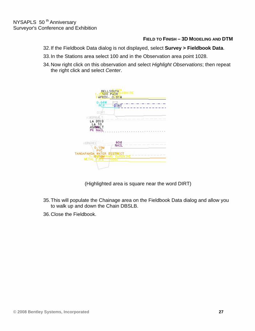
32. If the Fieldbook Data dialog is not displayed, select Survey > Fieldbook Data. 33. In the Stations area select 100 and in the Observation area point 1028. 34. Now right click on this observation and select Highlight Observations; then repeat
the right click and select Center.
(Highlighted area is square near the word DIRT)
35. This will populate the Chainage area on the Fieldbook Data dialog and allow you
to walk up and down the Chain DBSLB. 36. Close the Fieldbook.
NYSAPLS 50 th Anniversary Surveyor's Conference and Exhibition
© 2008 Bentley Systems, Incorporated 28
FIELD TO FINISH – 3D MODELING AND DTM
LESSON NAME: SURVEY DELIVERABLES
LESSON OBJECTIVE: In this lesson you will learn how to turn your newly imported survey data into ready to work with deliverables.
> EXERCISE: SURVEY DATA TO GEOMETRY
Creation of Geometry Data from the Imported Survey Data
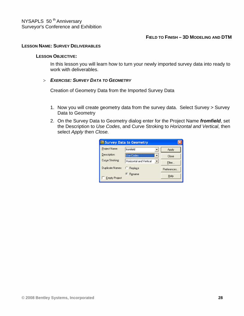
1. Now you will create geometry data from the survey data. Select Survey > Survey
Data to Geometry 2. On the Survey Data to Geometry dialog enter for the Project Name fromfield, set
the Description to Use Codes, and Curve Stroking to Horizontal and Vertical, then select Apply then Close.

NYSAPLS 50 th Anniversary Surveyor's Conference and Exhibition
© 2008 Bentley Systems, Incorporated 29
FIELD TO FINISH – 3D MODELING AND DTM
3. On the InRoads Survey explorer select the Geometry tab to review the alignment file created.
4. Right click on the alignment BDCLA on the InRoads Survey explorer and review the horizontal alignment.
NYSAPLS 50 th Anniversary Surveyor's Conference and Exhibition
© 2008 Bentley Systems, Incorporated 30
FIELD TO FINISH – 3D MODELING AND DTM
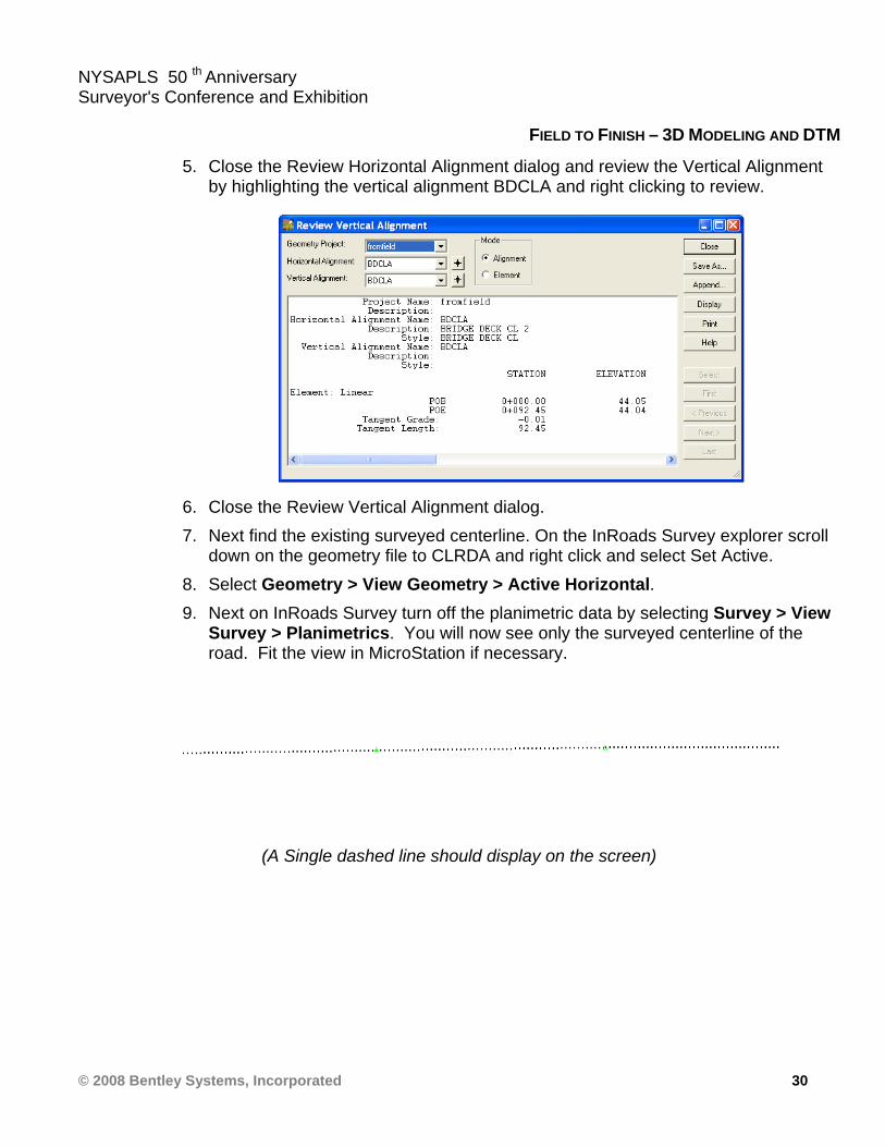
5. Close the Review Horizontal Alignment dialog and review the Vertical Alignment by highlighting the vertical alignment BDCLA and right clicking to review.
6. Close the Review Vertical Alignment dialog. 7. Next find the existing surveyed centerline. On the InRoads Survey explorer scroll
down on the geometry file to CLRDA and right click and select Set Active. 8. Select Geometry > View Geometry > Active Horizontal. 9. Next on InRoads Survey turn off the planimetric data by selecting Survey > View
Survey > Planimetrics. You will now see only the surveyed centerline of the road. Fit the view in MicroStation if necessary.
(A Single dashed line should display on the screen)
NYSAPLS 50 th Anniversary Surveyor's Conference and Exhibition
© 2008 Bentley Systems, Incorporated 31
FIELD TO FINISH – 3D MODELING AND DTM
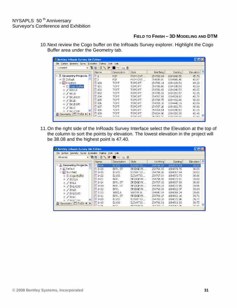
10. Next review the Cogo buffer on the InRoads Survey explorer. Highlight the Cogo Buffer area under the Geometry tab.
11. On the right side of the InRoads Survey Interface select the Elevation at the top of the column to sort the points by elevation. The lowest elevation in the project will be 38.08 and the highest point is 47.40.
NYSAPLS 50 th Anniversary Surveyor's Conference and Exhibition
© 2008 Bentley Systems, Incorporated 32
FIELD TO FINISH – 3D MODELING AND DTM
> EXERCISE: SURVEY DATA TO SURFACE
Creation of Surface from the Imported Survey Data
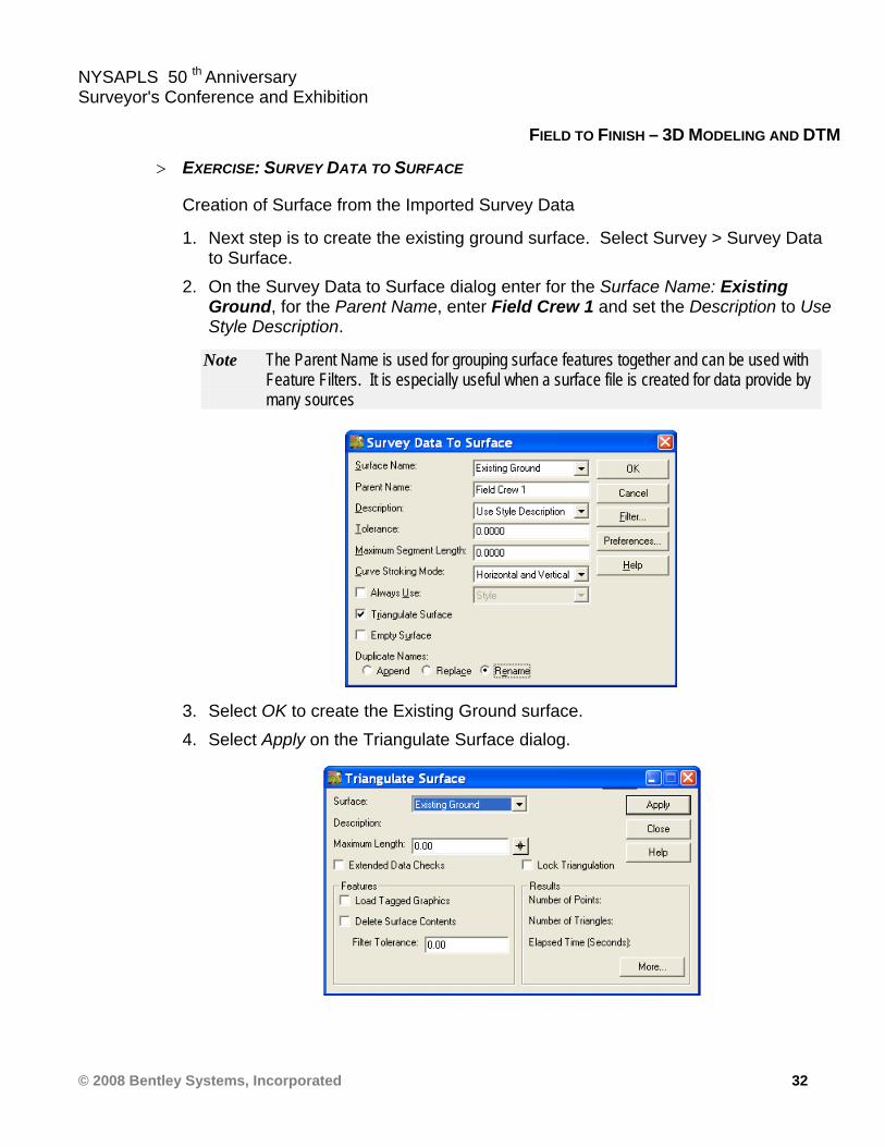
1. Next step is to create the existing ground surface. Select Survey > Survey Data to Surface.
2. On the Survey Data to Surface dialog enter for the Surface Name: Existing Ground, for the Parent Name, enter Field Crew 1 and set the Description to Use Style Description.
Note The Parent Name is used for grouping surface features together and can be used with Feature Filters. It is especially useful when a surface file is created for data provide by many sources
3. Select OK to create the Existing Ground surface. 4. Select Apply on the Triangulate Surface dialog.
NYSAPLS 50 th Anniversary Surveyor's Conference and Exhibition
© 2008 Bentley Systems, Incorporated 33
FIELD TO FINISH – 3D MODELING AND DTM
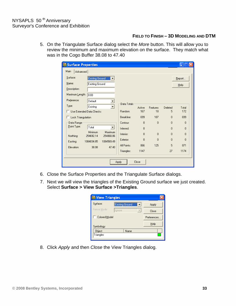
5. On the Triangulate Surface dialog select the More button. This will allow you to review the minimum and maximum elevation on the surface. They match what was in the Cogo Buffer 38.08 to 47.40
6. Close the Surface Properties and the Triangulate Surface dialogs. 7. Next we will view the triangles of the Existing Ground surface we just created.
Select Surface > View Surface >Triangles.
8. Click Apply and then Close the View Triangles dialog.
NYSAPLS 50 th Anniversary Surveyor's Conference and Exhibition
© 2008 Bentley Systems, Incorporated 34
FIELD TO FINISH – 3D MODELING AND DTM
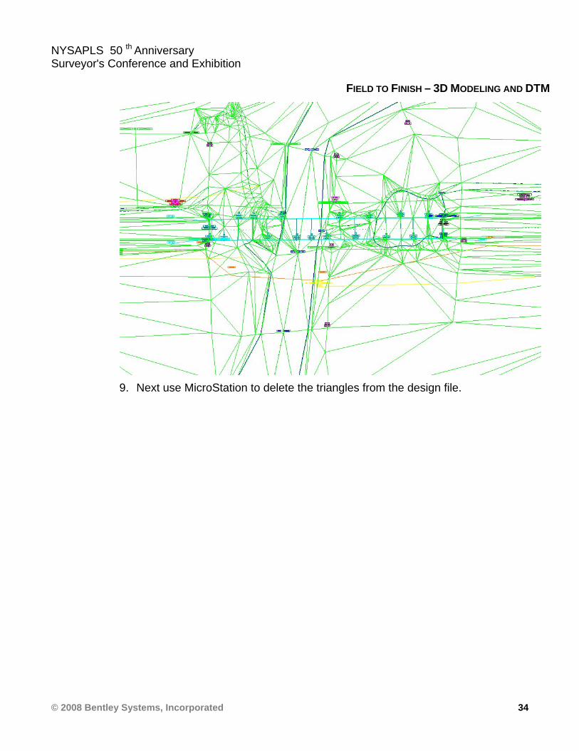
9. Next use MicroStation to delete the triangles from the design file.
NYSAPLS 50 th Anniversary Surveyor's Conference and Exhibition
© 2008 Bentley Systems, Incorporated 35
FIELD TO FINISH – 3D MODELING AND DTM
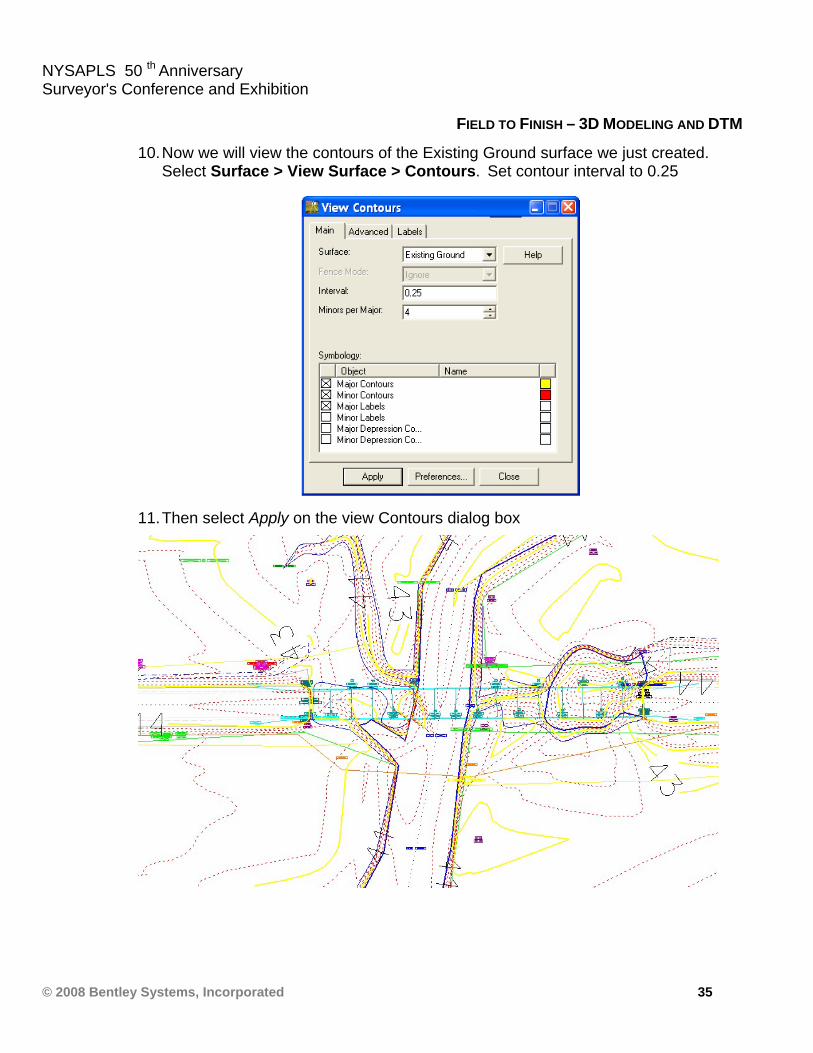
10. Now we will view the contours of the Existing Ground surface we just created. Select Surface > View Surface > Contours. Set contour interval to 0.25
11. Then select Apply on the view Contours dialog box
NYSAPLS 50 th Anniversary Surveyor's Conference and Exhibition
© 2008 Bentley Systems, Incorporated 36
FIELD TO FINISH – 3D MODELING AND DTM
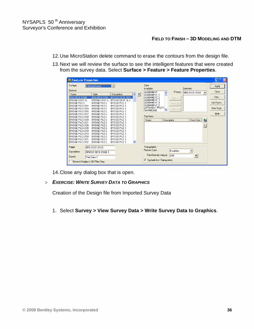
12. Use MicroStation delete command to erase the contours from the design file. 13. Next we will review the surface to see the intelligent features that were created
from the survey data. Select Surface > Feature > Feature Properties.
14. Close any dialog box that is open.
> EXERCISE: WRITE SURVEY DATA TO GRAPHICS
Creation of the Design file from Imported Survey Data
1. Select Survey > View Survey Data > Write Survey Data to Graphics.
NYSAPLS 50 th Anniversary Surveyor's Conference and Exhibition
© 2008 Bentley Systems, Incorporated 37
FIELD TO FINISH – 3D MODELING AND DTM
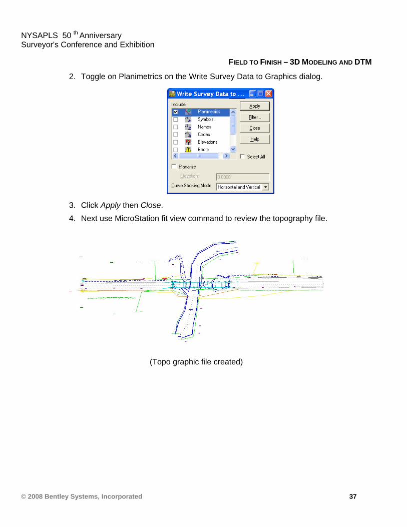
2. Toggle on Planimetrics on the Write Survey Data to Graphics dialog.
3. Click Apply then Close. 4. Next use MicroStation fit view command to review the topography file.
(Topo graphic file created)
NYSAPLS 50 th Anniversary Surveyor's Conference and Exhibition
© 2008 Bentley Systems, Incorporated 38
FIELD TO FINISH – 3D MODELING AND DTM
> EXERCISE: WRITE SURVEY DATA TO DRAINAGE
Creation of the Storm and Sanitary Database file from Imported Survey Data
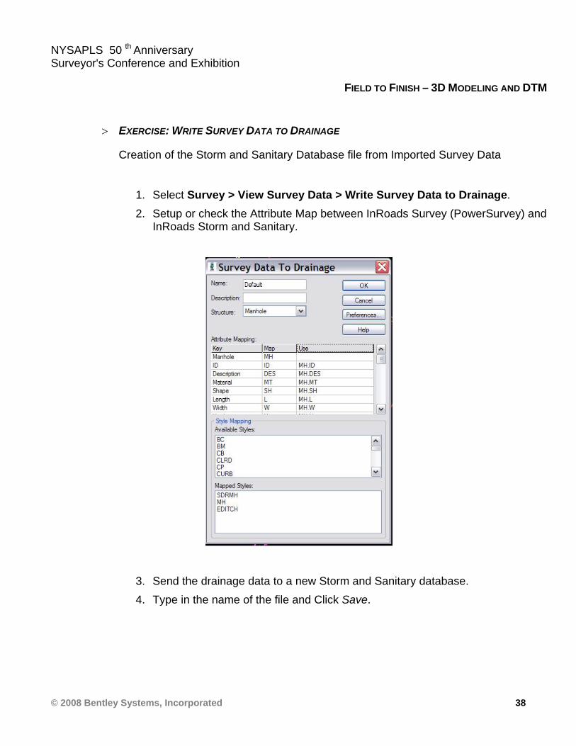
1. Select Survey > View Survey Data > Write Survey Data to Drainage. 2. Setup or check the Attribute Map between InRoads Survey (PowerSurvey) and
InRoads Storm and Sanitary.
3. Send the drainage data to a new Storm and Sanitary database. 4. Type in the name of the file and Click Save.