numerical simulations on jet impingement cooling of ... · distributions for flat plate impingement...
TRANSCRIPT
International Research Journal of Engineering and Technology (IRJET) e-ISSN: 2395-0056
Volume: 04 Issue: 07 | July -2017 www.irjet.net p-ISSN: 2395-0072
© 2017, IRJET | Impact Factor value: 5.181 | ISO 9001:2008 Certified Journal | Page 1650
Numerical simulations on jet impingement cooling of cylindrical
surfaces
Mr. Abhishek Lakshkar1, Dr. Santosh B. Bopche2
1PG Scholar, NIT Hamirpur, HP, India 2Assistant Professor, Dept. of Mechanical Engineering, NIT Hamirpur, HP, India
---------------------------------------------------------------------***---------------------------------------------------------------------Abstract - Lot of research has been perceived in the literature on the jet impingement cooling of flat surfaces and fewer contributions are available on the jet impingement cooling of cylindrical parts. The impingement of jet over the cylinder exhibits non-uniformity in the surface heat transfer coefficient in circumferential direction. The maximum heat transfer rate is observed at jet stagnation zone represented by zero lateral distance and local maximum of heat transfer rate occurs over the circumference due to transition from laminar to turbulent flow. The heat transfer rate onward to this location reduces upto the separation point where local minimum of heat transfer rate takes place. From separation point onwards up to the diametrically opposite location of jet impingement i.e., 180° first rising and then reducing heat transfer trend has been noticed. These observations are applicable to smooth cylindrical heat transfer surfaces. The parameters of study encompass jet flow Reynolds number and cylinder to jet diameter ratio. The present study results obtained for smooth cylinder surface were matches well with the literature outcomes. It is also found that the trend of Nusselt number distribution, decreases when the Reynolds number varies from 100 to 1000, increases for Reynolds number beyond 1000.
Key Words: Numerical Simulation, CFD, Jet Impingement Cooling, Nozzle, Cylindrical Surface, Nusselt Number.
1. INTRODUCTION A fluid stream generating from a nozzle at high velocity and that's why a high kinetic energy term as Jet. The fluid at high velocity impinges on the plate or vanes through a jet are known as Jet Impingement. Impingement cooling began finding its use in the cooling of heated surfaces (especially gas turbine blades and vanes) starting in the early 1960's. It has found that cooling in areas of high heat flux; jet impingement is a more effectual method of cooling than ordinary convection cooling.
1.1 Overview of Jet Impingement
The favourable heat transfer characteristics associated with impinging jets lend themselves to a variety of industrial heating, cooling, and drying applications. In various industrial applications, like cooling of electronics surfaces, GT blades, electrical machine rotors, material processing, steel/glass manufacturing processes, textiles, aerospace engineering,
automotive engines, cryogenics, refrigeration and air conditioning, nuclear reactors, fire engineering, food preservation, cooling of combustion chamber walls, etc., jet impingement finds its applications. It has found that cooling in areas of high heat flux; jet impingement is a more effective method of cooling than ordinary convection cooling. Depending on the application, jet impingement generally utilizes either single or an array of multiple fluid jets impinging on a target surface to achieve significantly enhanced convective heating, cooling, or drying characteristics. Such enhanced cooling characteristics are especially relevant to cylindrical furnace applications where the temperature inside the furnace can exceed 1800°C. However, such large enhancement comes at the cost of significant pressure drops incurred as the jet leaves the nozzle and impinges on the target surface; thus, impingement must be employed carefully to ensure the survival of the furnace body.
There are multiple broad reviews of flat plate impingement available in which details of heat transfer characteristics are presented [1 and 3]. The Nusselt numbers distributions for flat plate impingement are found to be dependent upon numerous parameters: the jet Reynolds number, the relative jet-to-target surface spacing and the amount of crossflow present near the target surface. Changes in geometry of jet also affect the heat transfer rate from the impinging surfaces. Chattopadhyay [5] has reported numerical study of heat transfer from annular impinging jet. It was observed that heat transfer when the annular jet utilized was about 20% lesser than that of the circular jet. The distribution pattern of the Nusselt number over the impinging surface scales with Re0.55. As well, changes in the jet – to – target surface spacing have little effect on heat transfer until the spacing is large enough that the lower velocities incurred by a diminished potential core cause the heat transfer coefficients to drop. The flat plate heat transfer distribution is compared with that of semi-cylindrical concave surface by Kayansyan and Kucuka [4] for confined slot air jet impingement. For the range of Re studied, the heat transfer rates in case of concave surface are observed to be more improved than that of the flat surface due to effects of channel curvature. The concave surface heat transfer rate is seen to be influenced by the jet-exit Re and the surface curvature while it is comparatively insensitive to the jet-to-target spacing [8]. The local Nu is found maximum at the stagnation point of semi-cylindrical concave surface jet impingement, whereas it shows a decreasing trend along the curvature of concave surface [11]. For a range of Reynolds number taken into consideration, the heat transfer rates from the concave surface are found to be more augmented than the
International Research Journal of Engineering and Technology (IRJET) e-ISSN: 2395-0056
Volume: 04 Issue: 07 | July -2017 www.irjet.net p-ISSN: 2395-0072
© 2017, IRJET | Impact Factor value: 5.181 | ISO 9001:2008 Certified Journal | Page 1651
flat surface due to effect of channel curvature [7]. Singh et al. [13] reported a heat transfer study to investigate the influence of shape of nozzle on jet impingement heat transfer from a circular cylinder. It is found that heat transfer rate from the cylinder is higher for rectangular nozzle in comparison to circular nozzle for a fixed Reynolds number. Singh et al. [15] reported a study of jet impingement cooling of a heated cylinder with turbulent circular air. It is detected that the NuStag rises monotonically with the decrease in h/d ratio and the effects of h/d and d/D are noteworthy only in the jet impinging region. The local circular jet heat transfer characteristics at fixed jet Reynolds number of ReJ = 20,000 have been discussed by Wang et al. [16].
From a thorough literature review it is concluded that cooling with jet impingement has been found good and effective method by various researchers. However, the study of cooling of circular rods with the application of jet impingement is very few in literature. So based on gap found in literature present study is divided in following sections:
a) Jet impingement over a smooth cylinder with varying cylinder diameter.
b) Effect of variation of Reynolds number on heat transfer and flow characteristics.
In the present study 2D jet impingement cooling of cylindrical rods in crossflow is simulated. A general purpose CFD code, ANSYS FLUENT a commercial CFD package, is chosen for fluid flow and heat transfer simulation of 2D jet impingement cooling of cylindrical rods. A CFD tool Ansys-Fluent is used to solve the basic governing equations of fluid flow. Ansys-Fluent implements finite volume method to solve the governing equation of the fluid flow.
2. THE PHYSICAL PROBLEM In present study, a stream of air issuing from a circular jet of diameter, DJ, impinges over the heated cylinder of diameter, D. The assumptions to the present problem include steady state, incompressible, two dimensional, axisymmetric and constant fluid properties. The cylindrical surface is considered to have a constant heat flux, q. The jet issuing from the nozzle is confined (in a circular domain). The distance between the exit of nozzle and the heater cylinder is z. The cylinder axis is aligned with the z axis and nozzle axis is aligned with the x axis. In the numerical study, the distance between the exit of nozzle and the target cylinder surface, z/DJ, was kept fixed and the ratio of cylinder to nozzle diameter, D/DJ, was varied. The diameter of the nozzle, DJ, was also kept fixed in the parametric study. Air at ambient conditions drawn by a centrifugal fan is discharged from a circular jet nozzle with a fixed inner diameter of DJ = 30mm [16]. The mass flow rate measured by an orifice plate is adjusted to fix the jet Reynolds number (ReJ) at 20,000 [16]. An acrylic (target) circular cylinder (ks ~ 0.02 W/m-K) is mounted on a linear traverse system to vary the impinging distance systematically [16]. The cases studied are discussed as follows.
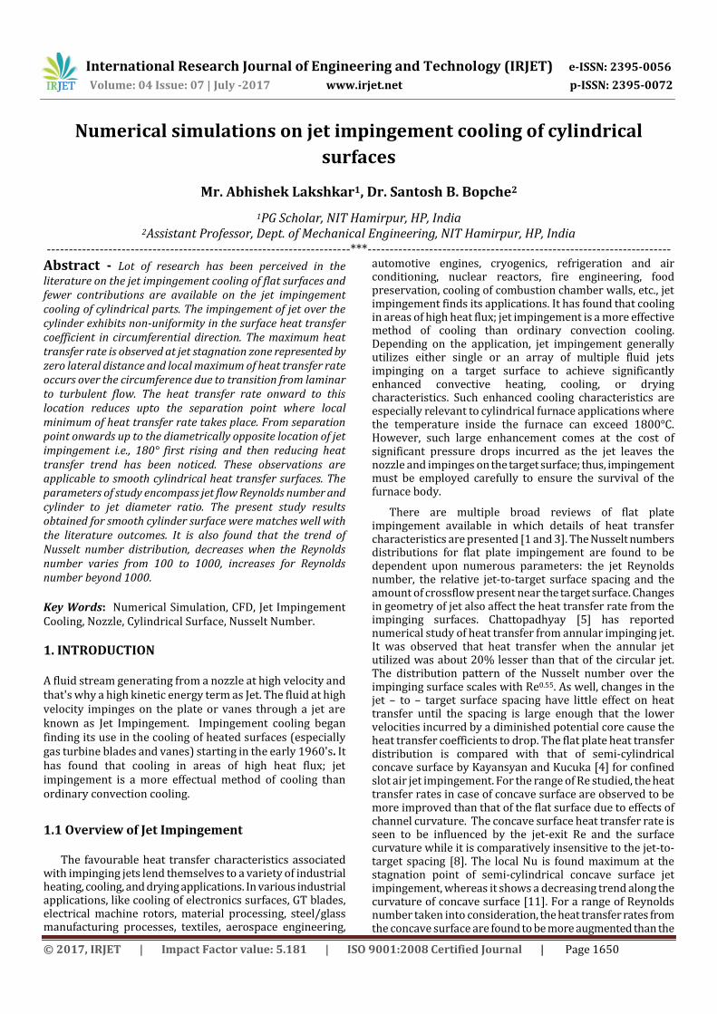
Fig -1: Description of circular jet flow impinging on circular bodies in crossflow with z/DJ = 2 and D/DJ = 0.5
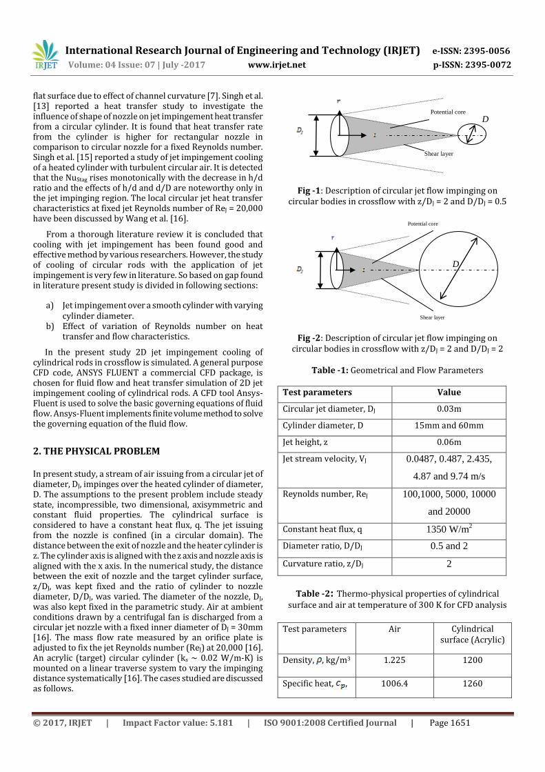
Fig -2: Description of circular jet flow impinging on circular bodies in crossflow with z/DJ = 2 and D/DJ = 2
Table -1: Geometrical and Flow Parameters
Test parameters Value
Circular jet diameter, DJ 0.03m
Cylinder diameter, D 15mm and 60mm
Jet height, z 0.06m
Jet stream velocity, VJ 0.0487, 0.487, 2.435,
4.87 and 9.74 m/s
Reynolds number, ReJ 100,1000, 5000, 10000
and 20000
Constant heat flux, q 1350 W/m2
Diameter ratio, D/DJ 0.5 and 2
Curvature ratio, z/DJ 2
Table -2: Thermo-physical properties of cylindrical surface and air at temperature of 300 K for CFD analysis
Test parameters Air Cylindrical
surface (Acrylic)
Density, , kg/m3 1.225 1200
Specific heat, , 1006.4 1260
Potential core
Shear layer
D
Potential core
Shear layer
D
International Research Journal of Engineering and Technology (IRJET) e-ISSN: 2395-0056
Volume: 04 Issue: 07 | July -2017 www.irjet.net p-ISSN: 2395-0072
© 2017, IRJET | Impact Factor value: 5.181 | ISO 9001:2008 Certified Journal | Page 1652
J/kg K
Thermal
conductivity, ,
W/m K
0.0242
0.02
Viscosity, ,
Ns/m2
-
Prandtl number,
0.744 -
3. NUMERICAL MODEL AND SOLUTION PROCEDURE The present physical problem of jet impingement cooling of cylindrical surfaces has been numerically studied assuming flow to be steady, incompressible, two dimensional and turbulent. For ease of computation k-ε turbulence model is used. Fig. 1 to Fig. 2 show the computational domain used in the present study which gives description of circular jet flow impinging on circular bodies in crossflow with z/DJ = 2 and D/DJ = 0.5, 2. The governing equations of continuity, momentum and energy are given in index notation
(1)
(2)
(3)
Where Ui, T and P are the average velocity, temperature and pressure, respectively. ui
’ and T’ are nothing but velocity and temperature components having fluctuation, respectively.
3.1 Solution Method ANSYS FLUENT is a multi-purpose computational fluid dynamics (CFD) software package to simulate fluid flow and heat transfer in complex geometries. It uses the finite volume method to solve the governing equations of continuity, momentum and energy. In the present simulation study, ANSYS FLUENT is used to solve the governing equations of continuity, momentum and energy in the steady state regime. For the numerical analysis a 2D model of flow domain built using GAMBIT is used. Grids of the concerning problem are generated with the help of GAMBIT. The model which is meshed in GAMBIT then exported to ANSYS FLUENT for numerical analysis. In pressure velocity compounding, SIMPLE (Semi-Implicit
Method for Pressure Linked Equations) algorithm is used in the discretization of governing equations. The set of equations used are solved using a pressure-based double-precision solver. For all the transport equations, second order upwind discretization schemes are used. The conservation equations are independently solved by the segregated solver and it is applicable to the incompressible flow only. The convergence criteria of 10-3 for residuals of continuity equation and velocity components and 10-6 for the residuals of the energy equation are assumed.
3.2 Boundary Conditions There are following boundary conditions are made to the problem.
a) Nozzle exit: At the exit of the nozzle, an UDF (User Defined Function) is used to impose the velocity distribution of a fully developed flow and the atmospheric conditions are used for the air at the exit of the nozzle.
b) Target wall: As cylinder being solid, therefore no slip boundary condition is used over the circular surface for momentum equations. Whereas to solve the energy equation, constant heat flux condition is used.
c) Other surfaces: Excluding the above boundary conditions (i.e. nozzle exit and target wall), all the remaining boundaries shown in Fig. 1 and 2 are considered as outlets with atmospheric pressure.
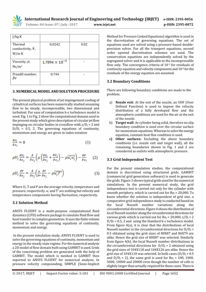
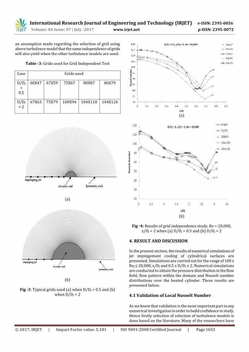
3.3 Grid Independent Test For the present simulation studies, the computational domain is discretized using structured grids. GAMBIT (commercial grid generation software) is used to generate the grids. Figure 3 shows typical grids used for the numerical simulations. In the present numerical study, the grid independence test is carried out only for the cylinder with smooth periphery, which is carried out for ReJ = 20,000. To know whether the solution is independent of grid size, a comparative grid independence study is conducted based on the local Nusselt number variations along the circumferential directions. Figure 4 shows the distribution of local Nusselt number along the circumferential directions for various grids which is carried out for ReJ = 20,000, z/DJ = 2 D/DJ = 0.5, 2 and using the Standard k-ε turbulence model. From figure 4(a), it is clear that the distributions of local Nusselt number in the circumferential directions for D/DJ = 0.5 obtained using the grid sizes of 80X87 and 86X79 are alike. Hence the grid size of 80X87 was selected. Similarly from figure 4(b), the local Nusselt number distributions in the circumferential directions for D/DJ = 2 obtained using the grid sizes of 104X118 and 104X126 are alike. Hence the grid size of 104X118 was selected. In both cases (D/DJ = 0.5 and D/DJ = 2), the same grid is used for ReJ = 100, 1000, 5000, 10000 and 20000 even though the number of cells is slightly larger than actually required for these cases. There is
International Research Journal of Engineering and Technology (IRJET) e-ISSN: 2395-0056
Volume: 04 Issue: 07 | July -2017 www.irjet.net p-ISSN: 2395-0072
© 2017, IRJET | Impact Factor value: 5.181 | ISO 9001:2008 Certified Journal | Page 1653
an assumption made regarding the selection of grid using above turbulence model that the same independence of grids will also yield when the other turbulence models are used.
Table -3: Grids used for Grid Independent Test
Case Grids used
D/DJ
= 0.5
60X47 67X59 75X67 80X87 86X79
D/DJ = 2
67X63 75X79 100X94 104X118 104X126
(a)
(b)
Fig -3: Typical grids used (a) when D/DJ = 0.5 and (b)
when D/DJ = 2
(a)
(b)
Fig -4: Results of grid independence study, Re = 20,000, z/DJ = 2 when (a) D/DJ = 0.5 and (b) D/DJ = 2
4. RESULT AND DISCUSSION In the present section, the results of numerical simulations of jet impingement cooling of cylindrical surfaces are presented. Simulations are carried out for the range of 100 ≤ ReJ ≤ 20,000, z/DJ and 0.5 ≤ D/DJ ≤ 2. Numerical simulations are conducted to obtain the pressure distribution in the flow field, flow pattern within the domain and Nusselt number distributions over the heated cylinder. These results are presented below.
4.1 Validation of Local Nusselt Number As we know that validation is the most important part in any numerical investigation in order to build confidence in study. Hence firstly selection of selection of turbulence models is done based on the literature. Many of the researchers have
International Research Journal of Engineering and Technology (IRJET) e-ISSN: 2395-0056
Volume: 04 Issue: 07 | July -2017 www.irjet.net p-ISSN: 2395-0072
© 2017, IRJET | Impact Factor value: 5.181 | ISO 9001:2008 Certified Journal | Page 1654
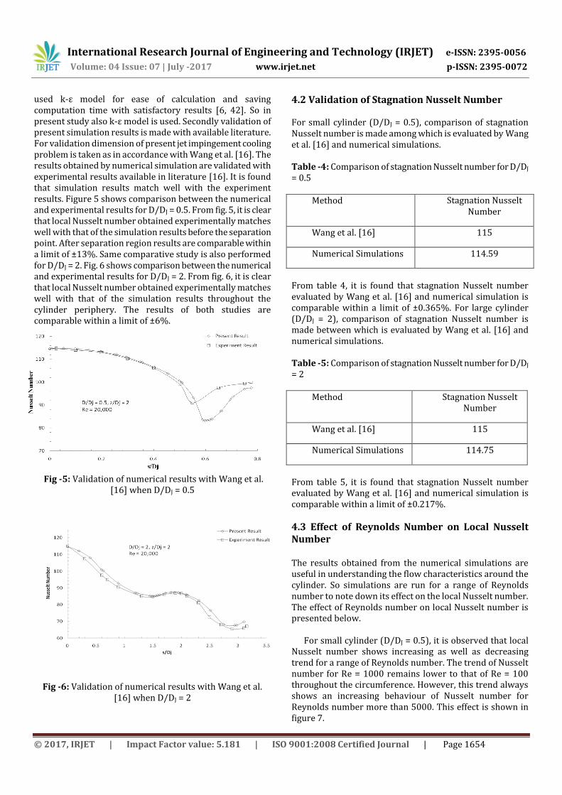
used k-ε model for ease of calculation and saving computation time with satisfactory results [6, 42]. So in present study also k-ε model is used. Secondly validation of present simulation results is made with available literature. For validation dimension of present jet impingement cooling problem is taken as in accordance with Wang et al. [16]. The results obtained by numerical simulation are validated with experimental results available in literature [16]. It is found that simulation results match well with the experiment results. Figure 5 shows comparison between the numerical and experimental results for D/DJ = 0.5. From fig. 5, it is clear that local Nusselt number obtained experimentally matches well with that of the simulation results before the separation point. After separation region results are comparable within a limit of ±13%. Same comparative study is also performed for D/DJ = 2. Fig. 6 shows comparison between the numerical and experimental results for D/DJ = 2. From fig. 6, it is clear that local Nusselt number obtained experimentally matches well with that of the simulation results throughout the cylinder periphery. The results of both studies are comparable within a limit of ±6%.
Fig -5: Validation of numerical results with Wang et al. [16] when D/DJ = 0.5
Fig -6: Validation of numerical results with Wang et al. [16] when D/DJ = 2
4.2 Validation of Stagnation Nusselt Number For small cylinder (D/DJ = 0.5), comparison of stagnation Nusselt number is made among which is evaluated by Wang et al. [16] and numerical simulations. Table -4: Comparison of stagnation Nusselt number for D/DJ = 0.5
Method Stagnation Nusselt Number
Wang et al. [16] 115
Numerical Simulations 114.59
From table 4, it is found that stagnation Nusselt number evaluated by Wang et al. [16] and numerical simulation is comparable within a limit of ±0.365%. For large cylinder (D/DJ = 2), comparison of stagnation Nusselt number is made between which is evaluated by Wang et al. [16] and numerical simulations. Table -5: Comparison of stagnation Nusselt number for D/DJ = 2
Method Stagnation Nusselt Number
Wang et al. [16] 115
Numerical Simulations 114.75
From table 5, it is found that stagnation Nusselt number evaluated by Wang et al. [16] and numerical simulation is comparable within a limit of ±0.217%.
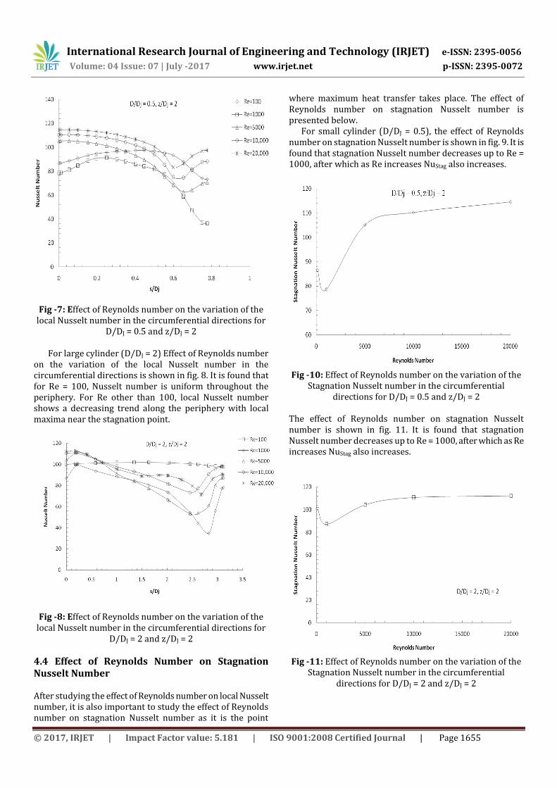
4.3 Effect of Reynolds Number on Local Nusselt Number The results obtained from the numerical simulations are useful in understanding the flow characteristics around the cylinder. So simulations are run for a range of Reynolds number to note down its effect on the local Nusselt number. The effect of Reynolds number on local Nusselt number is presented below. For small cylinder (D/DJ = 0.5), it is observed that local Nusselt number shows increasing as well as decreasing trend for a range of Reynolds number. The trend of Nusselt number for Re = 1000 remains lower to that of Re = 100 throughout the circumference. However, this trend always shows an increasing behaviour of Nusselt number for Reynolds number more than 5000. This effect is shown in figure 7.
International Research Journal of Engineering and Technology (IRJET) e-ISSN: 2395-0056
Volume: 04 Issue: 07 | July -2017 www.irjet.net p-ISSN: 2395-0072
© 2017, IRJET | Impact Factor value: 5.181 | ISO 9001:2008 Certified Journal | Page 1655
Fig -7: Effect of Reynolds number on the variation of the
local Nusselt number in the circumferential directions for D/DJ = 0.5 and z/DJ = 2
For large cylinder (D/DJ = 2) Effect of Reynolds number on the variation of the local Nusselt number in the circumferential directions is shown in fig. 8. It is found that for Re = 100, Nusselt number is uniform throughout the periphery. For Re other than 100, local Nusselt number shows a decreasing trend along the periphery with local maxima near the stagnation point.
Fig -8: Effect of Reynolds number on the variation of the
local Nusselt number in the circumferential directions for D/DJ = 2 and z/DJ = 2
4.4 Effect of Reynolds Number on Stagnation Nusselt Number After studying the effect of Reynolds number on local Nusselt number, it is also important to study the effect of Reynolds number on stagnation Nusselt number as it is the point
where maximum heat transfer takes place. The effect of Reynolds number on stagnation Nusselt number is presented below. For small cylinder (D/DJ = 0.5), the effect of Reynolds number on stagnation Nusselt number is shown in fig. 9. It is found that stagnation Nusselt number decreases up to Re = 1000, after which as Re increases NuStag also increases.
Fig -10: Effect of Reynolds number on the variation of the Stagnation Nusselt number in the circumferential
directions for D/DJ = 0.5 and z/DJ = 2 The effect of Reynolds number on stagnation Nusselt number is shown in fig. 11. It is found that stagnation Nusselt number decreases up to Re = 1000, after which as Re increases NuStag also increases.
Fig -11: Effect of Reynolds number on the variation of the Stagnation Nusselt number in the circumferential
directions for D/DJ = 2 and z/DJ = 2
International Research Journal of Engineering and Technology (IRJET) e-ISSN: 2395-0056
Volume: 04 Issue: 07 | July -2017 www.irjet.net p-ISSN: 2395-0072
© 2017, IRJET | Impact Factor value: 5.181 | ISO 9001:2008 Certified Journal | Page 1656
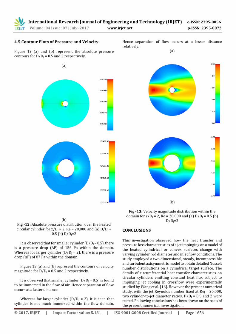
4.5 Contour Plots of Pressure and Velocity Figure 12 (a) and (b) represent the absolute pressure contours for D/DJ = 0.5 and 2 respectively.
(a)
(b) Fig -12: Absolute pressure distribution over the heated circular cylinder for z/DJ = 2, Re = 20,000 and (a) D/DJ =
0.5 (b) D/DJ=2 It is observed that for smaller cylinder (D/DJ = 0.5), there is a pressure drop (ΔP) of 156 Pa within the domain. Whereas for larger cylinder (D/DJ = 2), there is a pressure drop (ΔP) of 87 Pa within the domain. Figure 13 (a) and (b) represent the contours of velocity magnitude for D/DJ = 0.5 and 2 respectively. It is observed that smaller cylinder (D/DJ = 0.5) is found to be immersed in the flow of air. Hence separation of flow occurs at a latter distance. Whereas for larger cylinder (D/DJ = 2), it is seen that cylinder is not much immersed within the flow domain.
Hence separation of flow occurs at a lesser distance relatively.
(a)
(b)
Fig -13: Velocity magnitude distribution within the domain for z/DJ = 2, Re = 20,000 and (a) D/DJ = 0.5 (b)
D/DJ=2
CONCLUSIONS This investigation observed how the heat transfer and pressure loss characteristics of a jet impinging on a model of the heated cylindrical or convex surfaces change with varying cylinder rod diameter and inlet flow conditions. The study employed a two dimensional, steady, incompressible and turbulent axisymmetric model to obtain detailed Nusselt number distributions on a cylindrical target surface. The details of circumferential heat transfer characteristics on circular cylinders emitting constant heat flux subject to impinging jet cooling in crossflow were experimentally studied by Wang et al. [16]. However the present numerical study, with the jet Reynolds number fixed at ReJ = 20,000, two cylinder-to-jet diameter ratios, D/DJ = 0.5 and 2 were tested. Following conclusions has been drawn on the basis of the present numerical investigation:
International Research Journal of Engineering and Technology (IRJET) e-ISSN: 2395-0056
Volume: 04 Issue: 07 | July -2017 www.irjet.net p-ISSN: 2395-0072
© 2017, IRJET | Impact Factor value: 5.181 | ISO 9001:2008 Certified Journal | Page 1657
1) The results obtained by numerical simulation matches well with the experimental results of Wang et al. [16]. For D/DJ = 0.5, simulation results are comparable with experimental results within a limit of ±13% and for D/DJ = 2, simulation results are comparable with experimental results within a limit of ±6%.
2) The stagnation Nusselt number for the small cylinder (D/DJ = 0.5) is obtained by Wang et al. [16] and numerical simulation. It is found that stagnation Nusselt number evaluated by Wang et al. [16] and numerical simulation is comparable within a limit of ±0.365%.
3) The stagnation Nusselt number for the large cylinder (D/DJ = 2) is obtained by Wang et al. [16] and numerical simulation. it is found that stagnation Nusselt number evaluated by Wang et al. [16] and numerical simulation is comparable within a limit of ±0.217%.
4) For both cylinders, the trend of the local Nusselt number distribution shows a decreasing trend for a Reynolds number upto 1000. Whereas Re value beyond 1000, the trend of the local Nusselt number distribution shows an increasing trend.
5) For both cylinders, the stagnation Nusselt number first decreases upto Re = 1000. Beyond Re = 1000, stagnation Nusselt number increases.
REFERENCES [1] Livingood, J.N.B. and Hrycak, P., Impingement Heat
Transfer from Turbulent Air Jets to Flat Plates – a Literature Survey. Lewis Research Center, 1973.
[2] Rao, K.S., 1975, Numerical Study of Normal Impingement of a Plane Jet on a Flat Surface.
[3] Hrycak, P., Heat Transfer from Impinging Jets – a Literature Review. Air Force Wright Aeronautical Laboratories, 1981.
[4] Kayansyan, N. and Kucuka, S., Impingement Cooling of Semi-Cylindrical Concave Channel by Confined Slot Air Jet. Experimental Thermal and Fluid Science, 2001, 25, pp. 383-396.
[5] Chattopadhyay, H., Numerical Investigations of Heat Transfer from Impinging Annular Jet. International Journal of Heat and Fluid Flow, 2004, 47, pp. 3197-3201.
[6] Wang, S.J. and Mujumdar, A.S., A Comparative Study of Five Low Reynolds Number k–ε Models for Impingement Heat Transfer. Applied Thermal Engineering, 2005, 25, pp. 31-44.
[7] Hammoud, A. and Souidi, F., Modelling and Numerical Simulation of Laminar Carbon Monoxide-oxygen Flame Impinging on a Normal Solid Surface. Revue des Energies Renouvelables CISM’08 Oum El Bouaghi, 2008, pp. 145-152.
[8] Omar, A.M.T., Hamed, M.S. and Shoukri, M., Modelling of Nucleate Boiling Heat Transfer under an Impinging Free Jet. International Journal of Heat and Mass Transfer, 2009, 52, pp. 5557-5566.
[9] Koseoglu, M.F. and Baskaya, S., The Role of Jet Inlet Geometry in Impinging Jet Heat Transfer Modelling and
Experiments. International Journal of Thermal Sciences, 2010, 49, pp. 1417-1426.
[10] Sharif, M.A.R. and Mothe k.k., Parametric Study of Turbulent Slot-Jet Impingement Heat Transfer from Concave Cylindrical Surfaces. International Journal of Thermal Sciences, 2010, 49, pp. 428-442.
[11] Yang, Y.T., Wei, T.C. and Wang, Y.H., Numerical Study of Turbulent Slot Jet Impingement Cooling on a Semi-Circular Concave Surface. International Journal of Heat and Mass Transfer, 2011, 54, pp. 482-489.
[12] Katti, V., Sudheer, S., Prabhu, S.V., Pressure distribution on a semi-circular concave surface impinged by a single row of circular jets, Experimental Thermal and Fluid Science, 2013, vol. 46, pp. 162-174.
[13] Singh, D., Premachandran, B., and Kohli, S., Effect of nozzle shape on jet impingement heat transfer from a circular cylinder, International Journal of Thermal Sciences , 2015, vol. 96, pp. 45-69.
[14] Forooghi, P., Frohnapfel, B., and Magagnato, F., Simulation of a gaseous jet impinging on a convex heated surface – effect of inlet condition, Applied Thermal Engineering, 2016.
[15] Singh, D., Premachandran, B., and Kohli, S., Experimental and numerical investigation of jet impingement cooling of a circular cylinder, International Journal of Heat and Mass Transfer, 2013, vol. 60, pp. 672-688.
[16] Wang X. L., Lee J. H., Lu T. J., Song S. J., Kim T., A comparative study of single-/two-jet cross flow heat transfer on a circular cylinder, International Journal of Heat and Mass Transfer, 2014, vol. 78, pp. 588-598.