numerical simulation of unsteady interaction of hot...
TRANSCRIPT

Numerical simulation of unsteady interaction of hot
streams with HPT rotor blades using harmonic
balance method
A.I. Iakunin, N.B. Kuznetcov, N.N. Kortikov ,A.E.Tcvetaev
Klimov JSC, St. Petersburg, Russia
Theoretical Foundations of Thermotechnics Department,
St. Petersburg State Polytechnical University, Russia
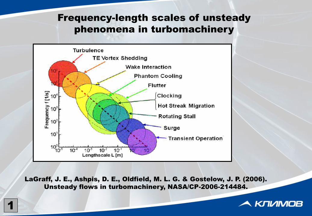
LaGraff, J. E., Ashpis, D. E., Oldfield, M. L. G. & Gostelow, J. P. (2006).
Unsteady flows in turbomachinery, NASA/CP-2006-214484.
Frequency-length scales of unsteady
phenomena in turbomachinery
1
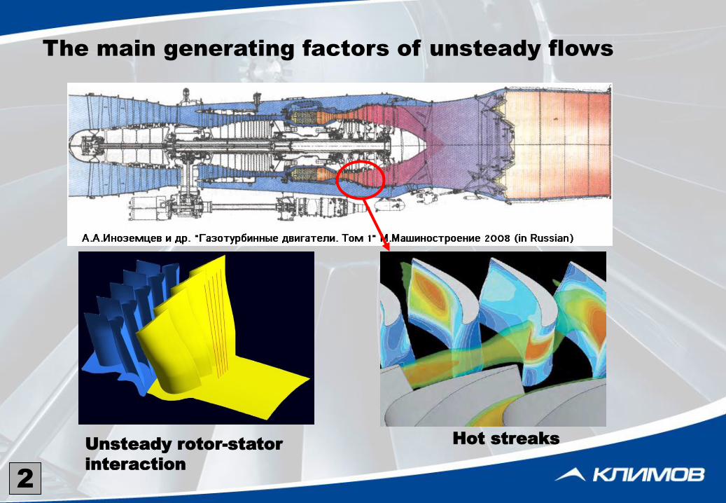
The main generating factors of unsteady flows
Hot streaks Unsteady rotor-stator
interaction
2
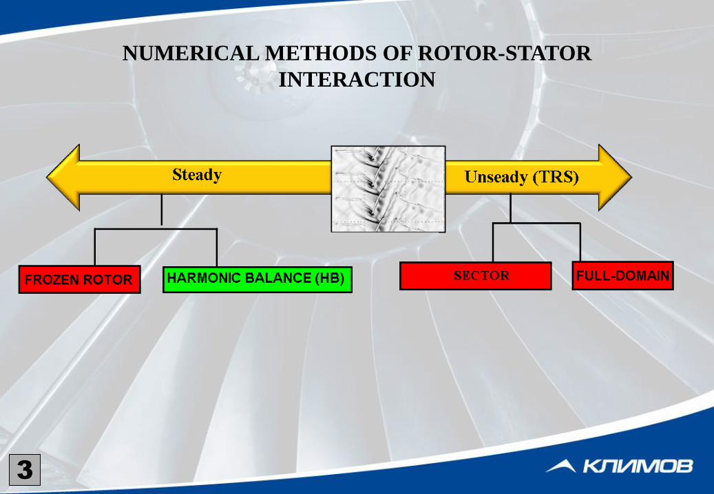
NUMERICAL METHODS OF ROTOR-STATOR
INTERACTION
3
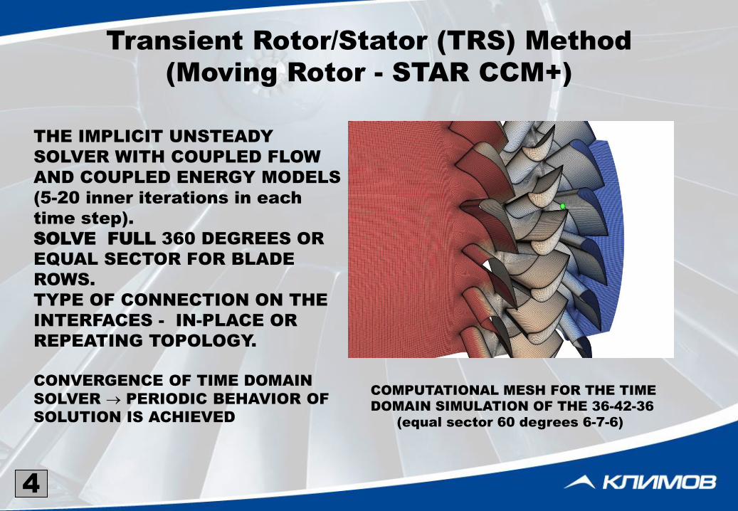
Transient Rotor/Stator (TRS) Method
(Moving Rotor - STAR CCM+)
THE IMPLICIT UNSTEADY
SOLVER WITH COUPLED FLOW
AND COUPLED ENERGY MODELS
(5-20 inner iterations in each
time step).
SOLVE FULL 360 DEGREES OR
EQUAL SECTOR FOR BLADE
ROWS.
TYPE OF CONNECTION ON THE
INTERFACES - IN-PLACE OR
REPEATING TOPOLOGY.
CONVERGENCE OF TIME DOMAIN
SOLVER PERIODIC BEHAVIOR OF
SOLUTION IS ACHIEVED
COMPUTATIONAL MESH FOR THE TIME
DOMAIN SIMULATION OF THE 36-42-36
(equal sector 60 degrees 6-7-6)
4
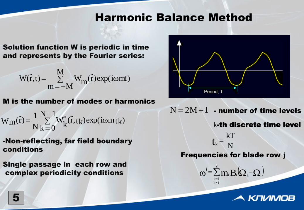
Harmonic Balance Method
Solution function W is periodic in time
and represents by the Fourier series:
M is the number of modes or harmonics
-Non-reflecting, far field boundary
conditions
Single passage in each row and
complex periodicity conditions
5
)mtiexp()r(M
MmmW)t,r(W
N
kTtk
1M2N - number of time levels
k-th discrete time level
Z
ji1i
ijii
j
Bm
Frequencies for blade row j
)tkmiexp()tk,r(1N
0k kW
N
1)r(Wm
*
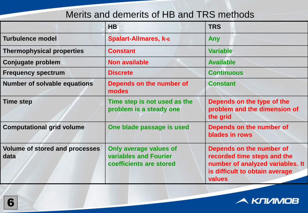
Merits and demerits of HB and TRS methods
HB TRS
Turbulence model Spalart-Allmares, k-e Any
Thermophysical properties Constant Variable
Conjugate problem Non available Available
Frequency spectrum Discrete Continuous
Number of solvable equations Depends on the number of
modes
Constant
Time step Time step is not used as the
problem is a steady one
Depends on the type of the
problem and the dimension of
the grid
Computational grid volume One blade passage is used Depends on the number of
blades in rows
Volume of stored and processes
data
Only average values of
variables and Fourier
coefficients are stored
Depends on the number of
recorded time steps and the
number of analyzed variables. It
is difficult to obtain average
values
6
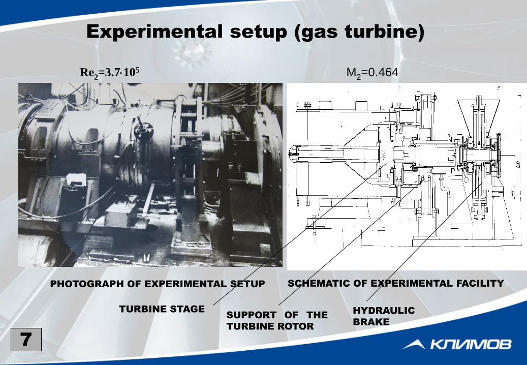
Experimental setup (gas turbine)
SCHEMATIC OF EXPERIMENTAL FACILITY PHOTOGRAPH OF EXPERIMENTAL SETUP
7
TURBINE STAGE SUPPORT OF THE
TURBINE ROTOR
HYDRAULIC
BRAKE
Re2=3.7105 M2=0.464

Basic parameters for physical modeling
SECTION D m
g1
m
g2
m
c1
m
C2
m
1
DEGREES
1
DEGREES
2
DEGREES
BOTTOM 0.36 0.0471 0.0269 0.078 0.035 25010’ 34016’ 36030’
MID - SPAN 0.43 0.0562 0.0322 0.078 0.037 26020’ 58025’ 34032’
TOP 0.50 0.0654 0.0374 0.078 0.043 28020’ 94050’ 30016’
ZS=24
ZR=48
Re2=3.7105
Mw2=0.464
=5000 rpm
FLOW SCHEME AND MEASUREMENT LOCATIONS IN THE
TURBINE STAGE
8
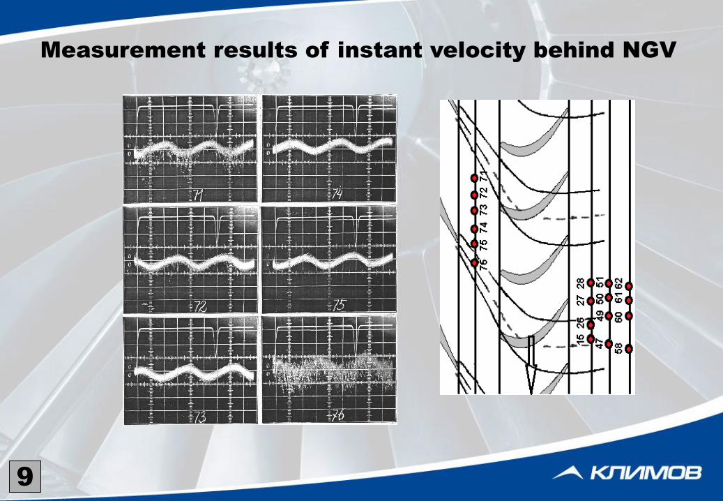
Measurement results of instant velocity behind NGV
9

Measurement results of instant velocity
behind wheel in three sections
10
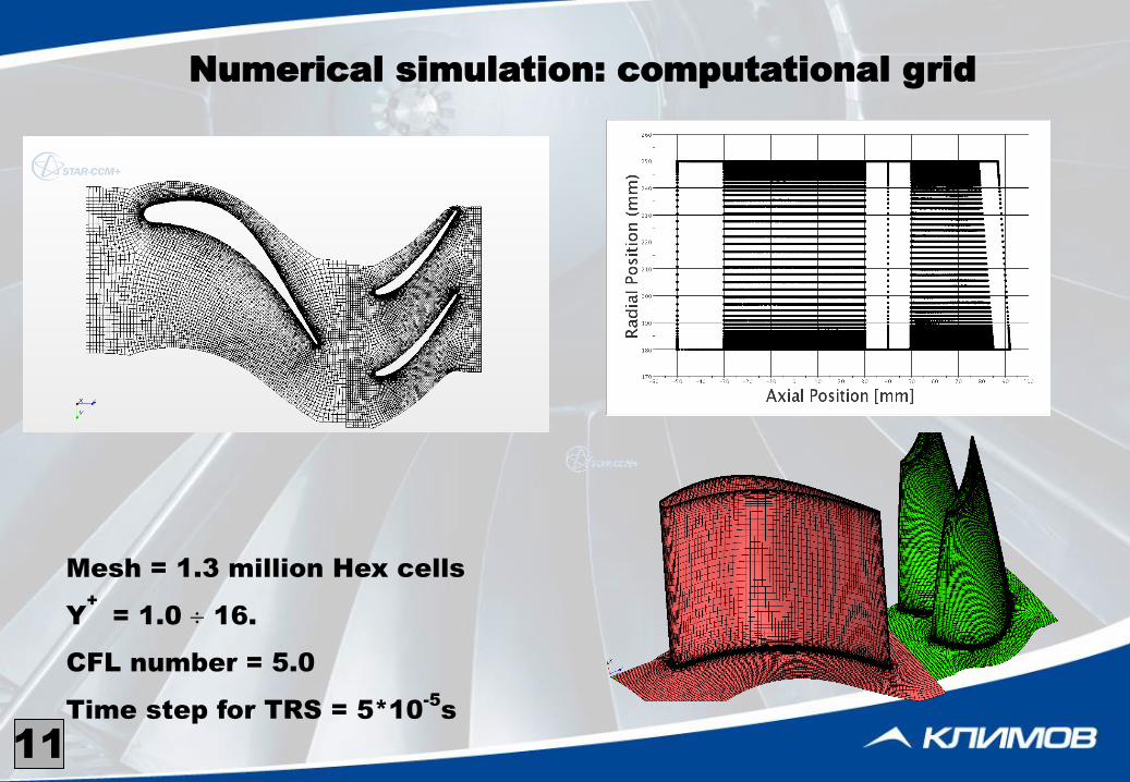
Mesh = 1.3 million Hex cells
Y
+
= 1.0 16.
CFL number = 5.0
Time step for TRS = 5*10-5
s
Numerical simulation: computational grid
11
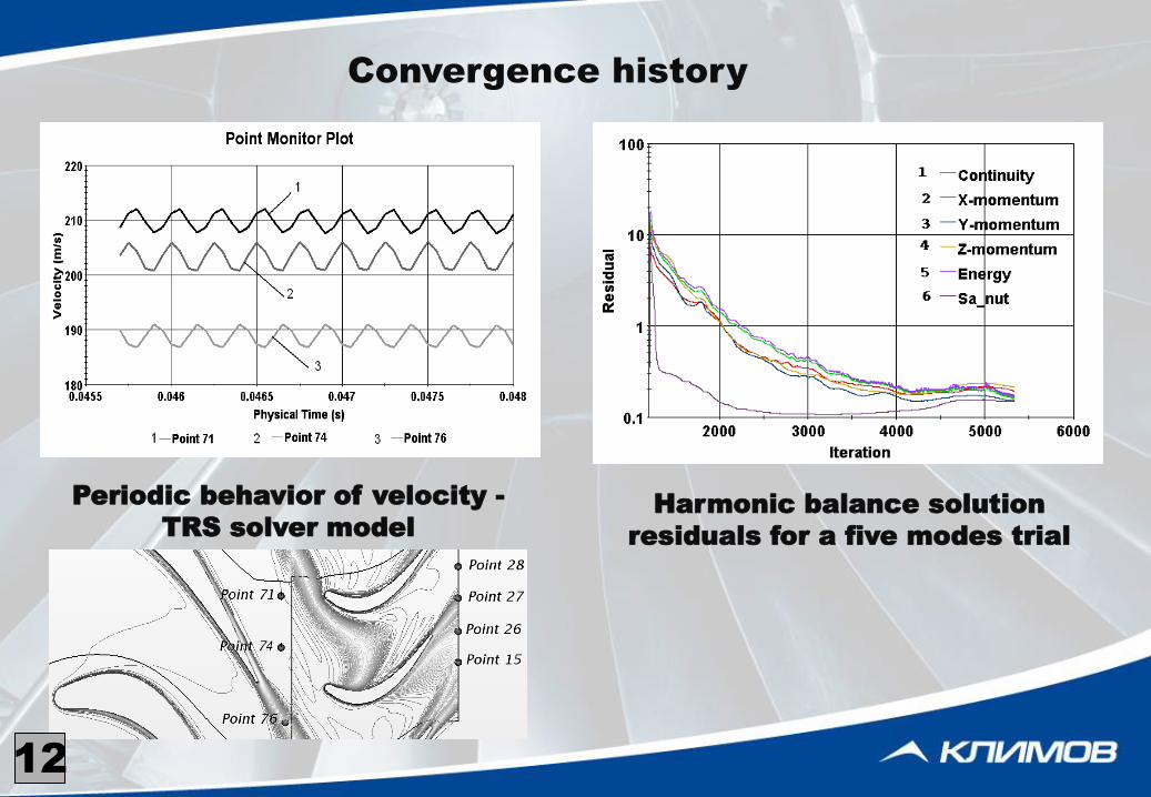
Harmonic balance solution
residuals for a five modes trial
Periodic behavior of velocity -
TRS solver model
Convergence history
12
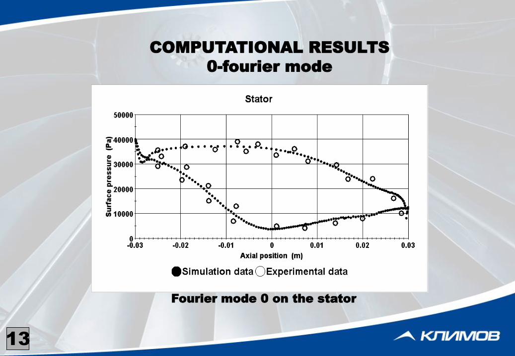
Fourier mode 0 on the stator
(a)
COMPUTATIONAL RESULTS
0-fourier mode
13
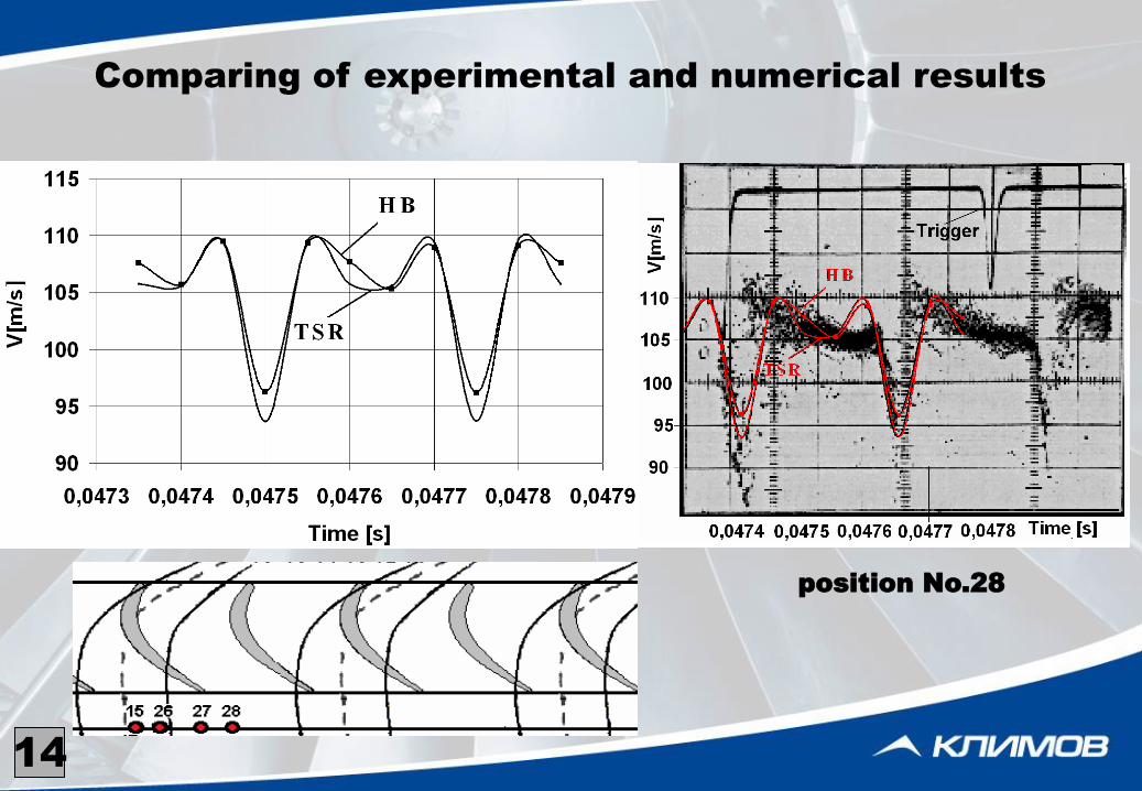
Comparing of experimental and numerical results
position No.28
14
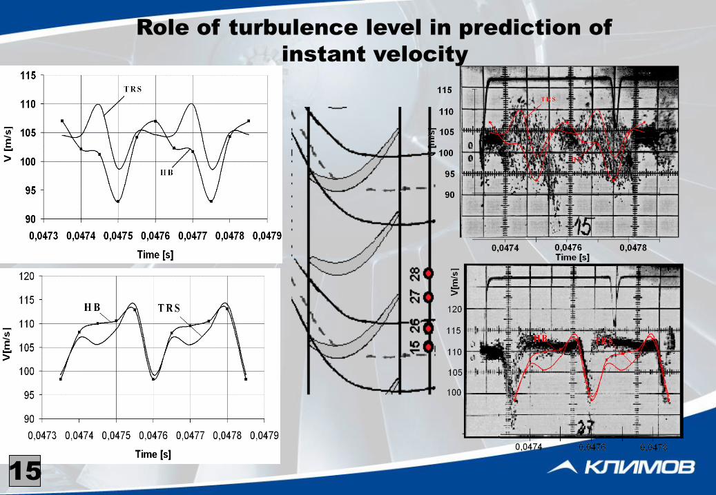
Role of turbulence level in prediction of
instant velocity
15
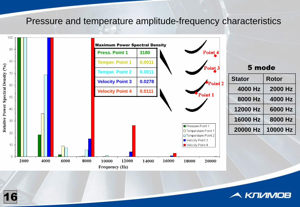
Pressure and temperature amplitude-frequency characteristics
Stator Rotor
4000 Hz 2000 Hz
8000 Hz 4000 Hz
12000 Hz 6000 Hz
16000 Hz 8000 Hz
20000 Hz 10000 Hz
5 mode
16
Press. Point 1 3180
Temper. Point 1 0.0011
Temper. Point 2 0.0011
Velocity Point 3 0.0278
Velocity Point 4 0.0111
Maximum Power Spectral Density
17
18
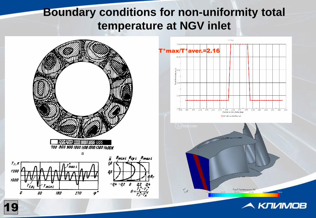
Boundary conditions for non-uniformity total
temperature at NGV inlet
T*max/T*aver.=2.16
19
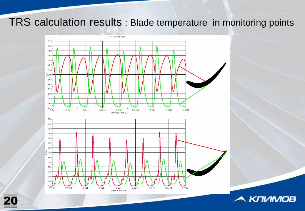
TRS calculation results : Blade temperature in monitoring points
20
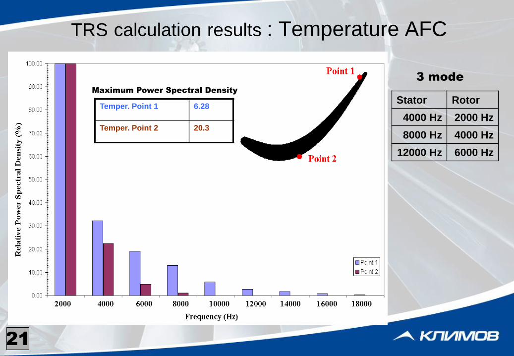
TRS calculation results : Temperature AFC
21
Temper. Point 1 6.28
Temper. Point 2 20.3
Stator Rotor
4000 Hz 2000 Hz
8000 Hz 4000 Hz
12000 Hz 6000 Hz
3 mode
Maximum Power Spectral Density
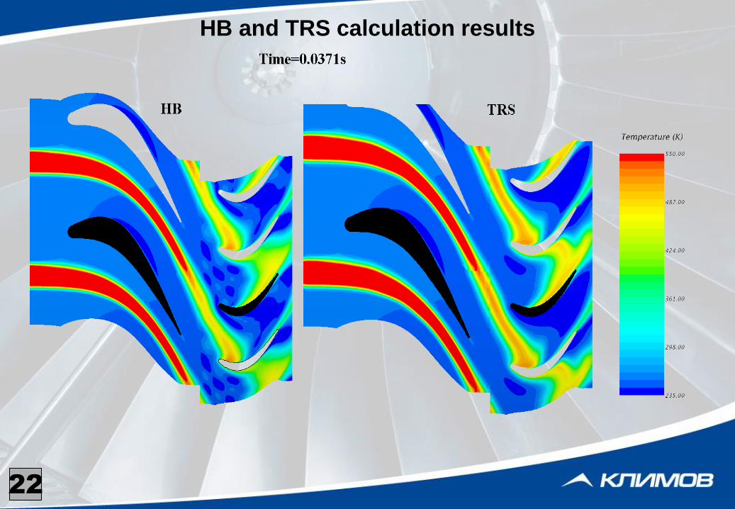
HB and TRS calculation results
22

HB and TRS calculation results
23
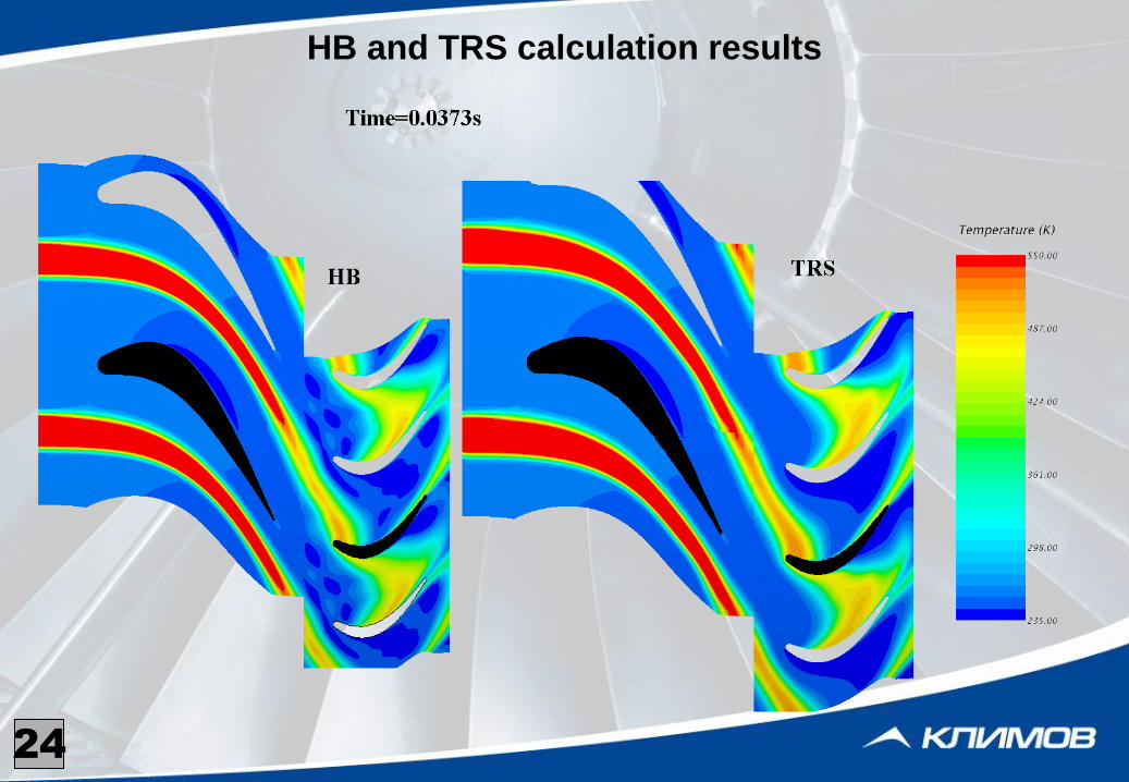
HB and TRS calculation results
24
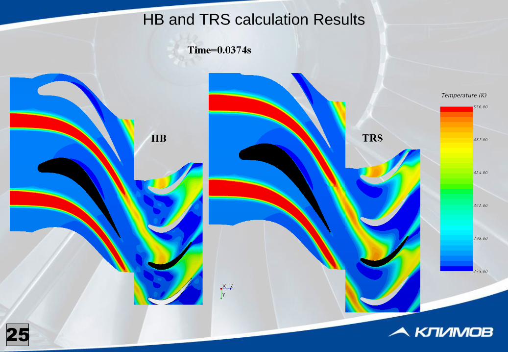
HB and TRS calculation Results
25

HB and TRS calculation results
26
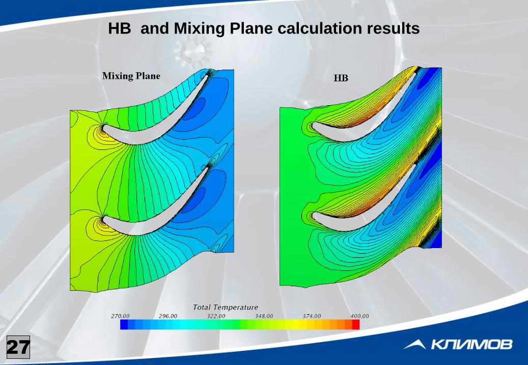
HB and Mixing Plane calculation results
27
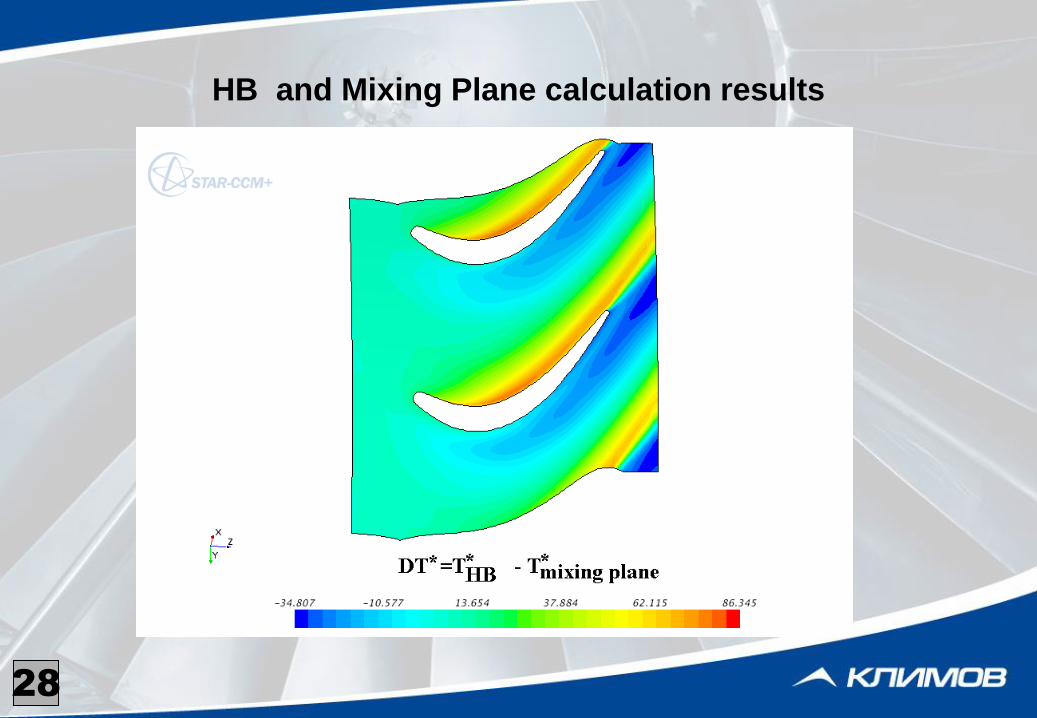
HB and Mixing Plane calculation results
28
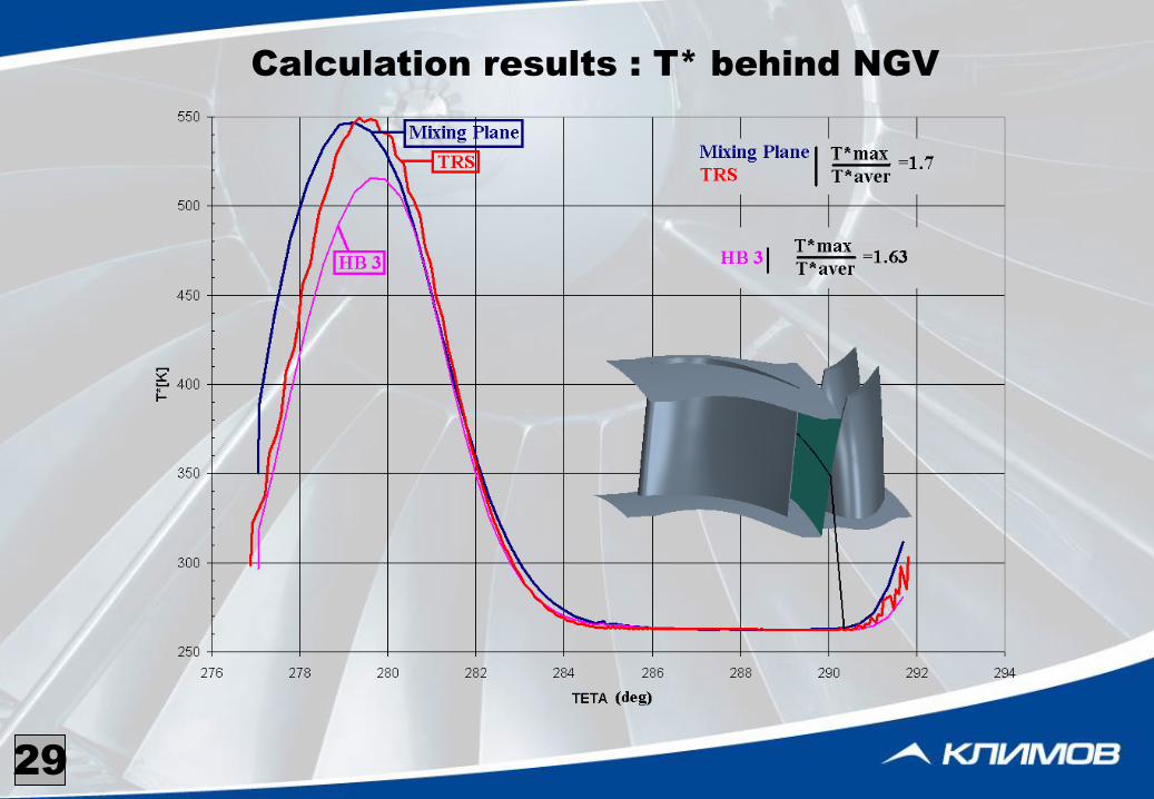
Calculation results : T* behind NGV
29
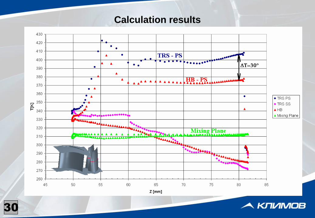
Calculation results
30
Conclusions
• During calculation of unsteady time and space periodic gas flows in
turbomachines the HB method is considerably more effective in terms of the
calculation costs in comparison with TRS method;
• Comparison of the calculation results with the experimental data has shown a
good match for both methods excluding the interaction of the NGV wake with
the rotor wheel at the turbine outlet;
• Calculations of effect of the circular temperature non-uniformity on the
temperature of the rotor blades have proved a possibility of use of the HB
method for the engineering analyses with a possible inaccuracy of up to 8-9%;
• Similar match of the calculation results using HB and TRS methods permits to
use effectively the HB method for optimization calculations.
31
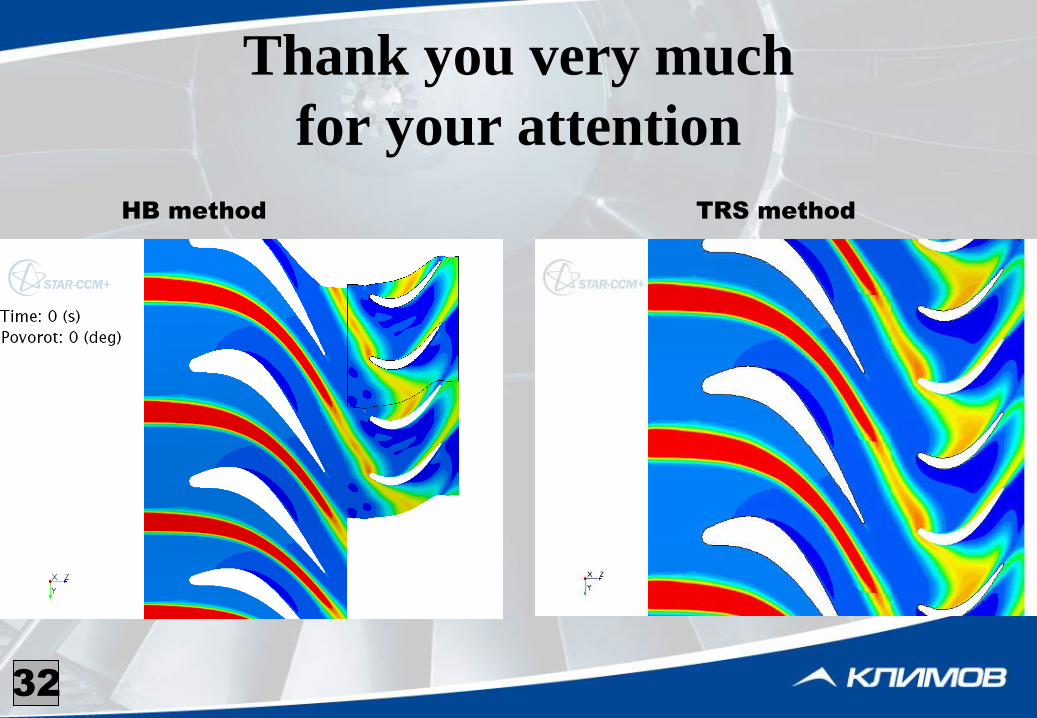
Thank you very much
for your attention
TRS method
32
HB method
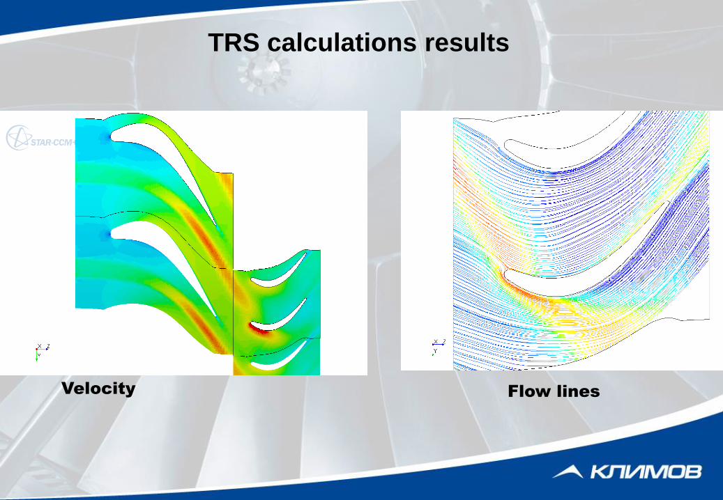
TRS calculations results
Velocity Flow lines