novel application of organic rankine cycle (orc ... · orc units, a new orc exit collector was...
TRANSCRIPT
Novel Application of Organic Rankine Cycle (ORC) Technology for Waste Heat Recovery
from Reheat Furnace Evaporative Cooling System
Ahmet DURMAZ TMEIC
2060 Cook Drive Salem, VA 24153, USA
Tel: 540-283-2000 Fax: 540-283-2395
E-mail: [email protected]
Ralph Pugh TMEIC 2060 Cook Drive Salem, VA 24153, USA Tel: 540-283-2158 Fax: 540-283-2395 E-mail: [email protected]
Şaban YAZICI Kasım ERDOĞAN Abbas KOŞAN TOSÇELİK TOSÇELİK TOSÇELİK
Osmaniye OSB Turkey Osmaniye OSB Turkey Osmaniye OSB Turkey Tel: +90 328 826 80 80 Tel: +90 328 826 80 80 Tel: +90 328 826 80 80 Fax: +90 328 826 80 09 Fax: +90 328 826 80 09 Fax: +90 328 826 80 09 E-mail: [email protected] E-mail: [email protected] E-mail: [email protected]
Keywords: Organic Rankine Cycle, Energy Savings, Slab Reheat Furnace, Waste Heat Recovery
INTRODUCTION
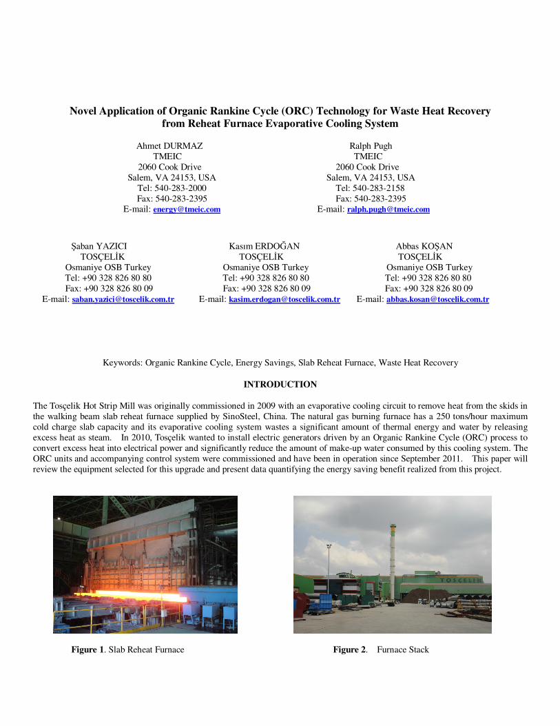
The Tosçelik Hot Strip Mill was originally commissioned in 2009 with an evaporative cooling circuit to remove heat from the skids in the walking beam slab reheat furnace supplied by SinoSteel, China. The natural gas burning furnace has a 250 tons/hour maximum cold charge slab capacity and its evaporative cooling system wastes a significant amount of thermal energy and water by releasing excess heat as steam. In 2010, Tosçelik wanted to install electric generators driven by an Organic Rankine Cycle (ORC) process to convert excess heat into electrical power and significantly reduce the amount of make-up water consumed by this cooling system. The ORC units and accompanying control system were commissioned and have been in operation since September 2011. This paper will review the equipment selected for this upgrade and present data quantifying the energy saving benefit realized from this project.
Figure 1. Slab Reheat Furnace Figure 2. Furnace Stack
BACKGROUND
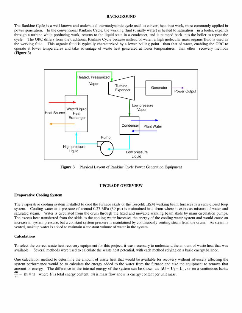
The Rankine Cycle is a well known and understood thermodynamic cycle used to convert heat into work, most commonly applied in power generation. In the conventional Rankine Cycle, the working fluid (usually water) is heated to saturation in a boiler, expands through a turbine while producing work, returns to the liquid state in a condenser, and is pumped back into the boiler to repeat the cycle. The ORC differs from the traditional Rankine Cycle because instead of water, a high molecular mass organic fluid is used as the working fluid. This organic fluid is typically characterized by a lower boiling point than that of water, enabling the ORC to operate at lower temperatures and take advantage of waste heat generated at lower temperatures than other recovery methods (Figure 3)
Figure 3. Physical Layout of Rankine Cycle Power Generation Equipment
UPGRADE OVERVIEW
Evaporative Cooling System
The evaporative cooling system installed to cool the furnace skids of the Tosçelik HSM walking beam furnaces is a semi-closed loop system. Cooling water at a pressure of around 0.27 MPa (39 psi) is maintained in a drum where it exists as mixture of water and saturated steam. Water is circulated from the drum through the fixed and movable walking beam skids by main circulation pumps. The excess heat transferred from the skids to the cooling water increases the energy of the cooling water system and would cause an increase in system pressure, but a constant system pressure is maintained by continuously venting steam from the drum. As steam is vented, makeup water is added to maintain a constant volume of water in the system.
Calculations
To select the correct waste heat recovery equipment for this project, it was necessary to understand the amount of waste heat that was available. Several methods were used to calculate the waste heat potential, with each method relying on a basic energy balance.
One calculation method to determine the amount of waste heat that would be available for recovery without adversely affecting the system performance would be to calculate the energy added to the water from the furnace and size the equipment to remove that amount of energy. The difference in the internal energy of the system can be shown as: ∆U = U2 – U1 , or on a continuous basis: ��
��� �� � where U is total energy content, �� is mass flow and u is energy content per unit mass.
Water/ Liquid
Heat Exchanger
Heat Source
Turbine Expander
GeneratorPower Output
Heated, Pressurized
Vapor
Condenser Plant Water
Low pressure Vapor
Low pressureLiquid
High pressureLiquid
Pump
Water is being circulated through the system at a rate of 161 kg/sec, and the supply and return water temperatures are around 127°C and 142° C, respectively. Using standard tables for the internal energy of water, it can be determined that energy is being added to the system at a rate of 10,319 kJ/sec, or 10,319 kW.
sec319,10)(
sec161)(
1271421212 kJ
uukg
dt
dUuum
dt
dU
t
UU
t
UCC
oo =−∗=→−∗=→∆
−=
∆
∆ •
Equation 1
At full capacity it was estimated that a standard ORC unit would require about 3196 kJ/sec of thermal energy to produce 250 kW net electrical power. Based on the result of Equation 1, it was estimated that there was enough excess heat to supply 3 ORC units. Other heat calculation methods such as using the amount of make-up water consumption, pointed to less heat availability, just enough to feed 2 ORC units. At the end, Tosçelik decided to install 4 x 250 kW ORC units thinking about future expansion such as applying waste heat recovery to exhaust flue gases in the event there is unused excess capacity.
New Equipment Installation
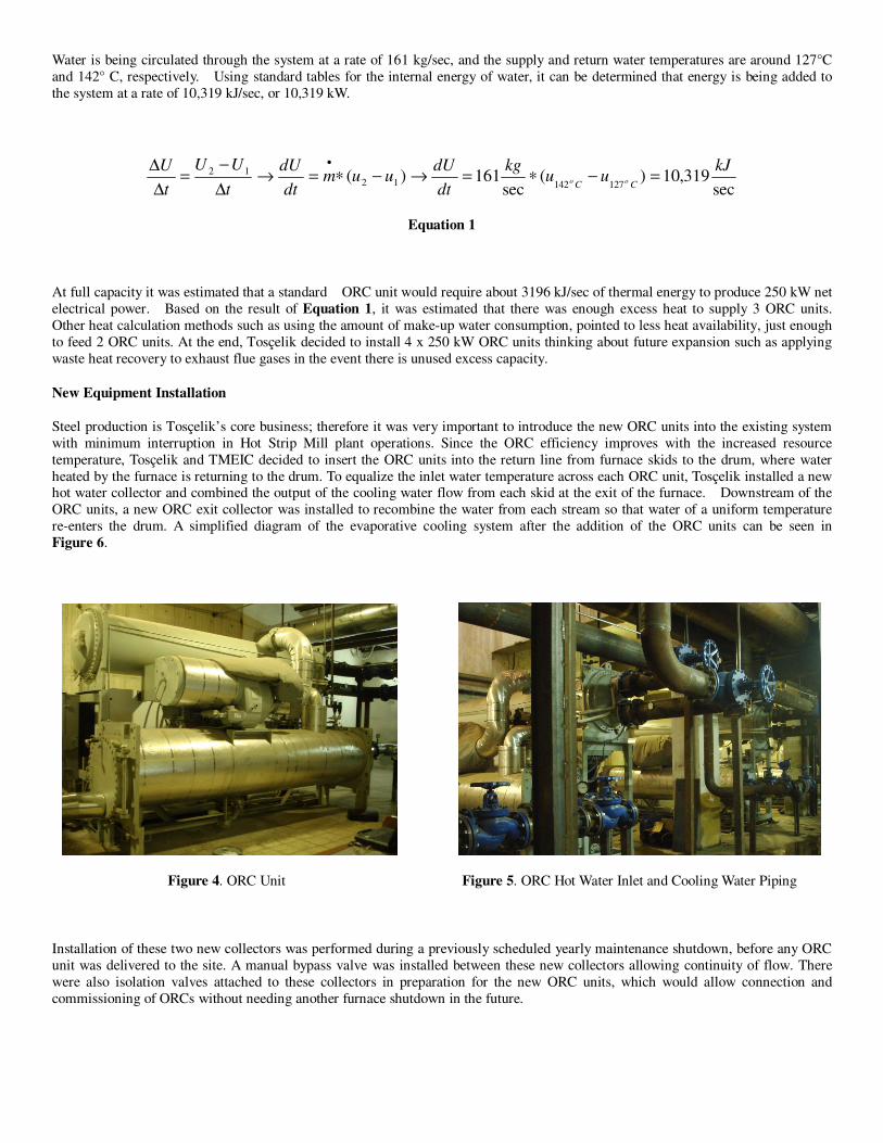
Steel production is Tosçelik’s core business; therefore it was very important to introduce the new ORC units into the existing system with minimum interruption in Hot Strip Mill plant operations. Since the ORC efficiency improves with the increased resource temperature, Tosçelik and TMEIC decided to insert the ORC units into the return line from furnace skids to the drum, where water heated by the furnace is returning to the drum. To equalize the inlet water temperature across each ORC unit, Tosçelik installed a new hot water collector and combined the output of the cooling water flow from each skid at the exit of the furnace. Downstream of the ORC units, a new ORC exit collector was installed to recombine the water from each stream so that water of a uniform temperature re-enters the drum. A simplified diagram of the evaporative cooling system after the addition of the ORC units can be seen in Figure 6.
Figure 4. ORC Unit Figure 5. ORC Hot Water Inlet and Cooling Water Piping
Installation of these two new collectors was performed during a previously scheduled yearly maintenance shutdown, before any ORC unit was delivered to the site. A manual bypass valve was installed between these new collectors allowing continuity of flow. There were also isolation valves attached to these collectors in preparation for the new ORC units, which would allow connection and commissioning of ORCs without needing another furnace shutdown in the future.
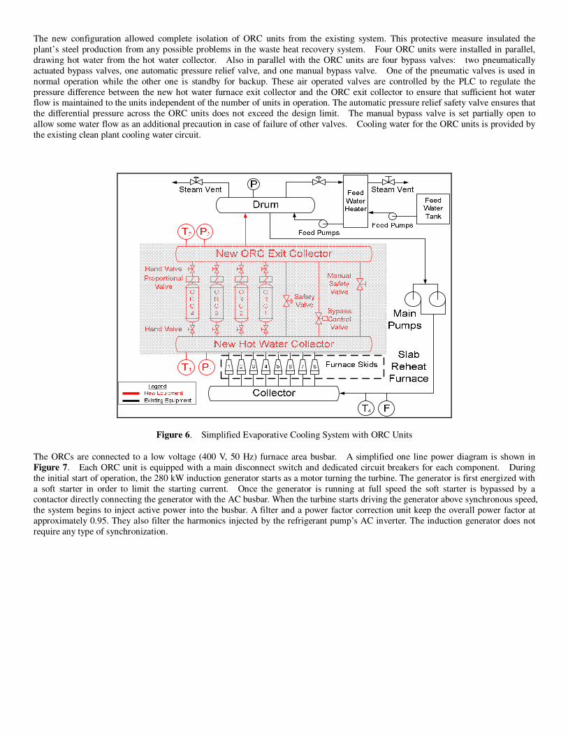
The new configuration allowed complete isolation of ORC units from the existing system. This protective measure insulated the plant’s steel production from any possible problems in the waste heat recovery system. Four ORC units were installed in parallel, drawing hot water from the hot water collector. Also in parallel with the ORC units are four bypass valves: two pneumatically actuated bypass valves, one automatic pressure relief valve, and one manual bypass valve. One of the pneumatic valves is used in normal operation while the other one is standby for backup. These air operated valves are controlled by the PLC to regulate the pressure difference between the new hot water furnace exit collector and the ORC exit collector to ensure that sufficient hot water flow is maintained to the units independent of the number of units in operation. The automatic pressure relief safety valve ensures that the differential pressure across the ORC units does not exceed the design limit. The manual bypass valve is set partially open to allow some water flow as an additional precaution in case of failure of other valves. Cooling water for the ORC units is provided by the existing clean plant cooling water circuit.
Figure 6. Simplified Evaporative Cooling System with ORC Units
The ORCs are connected to a low voltage (400 V, 50 Hz) furnace area busbar. A simplified one line power diagram is shown in Figure 7. Each ORC unit is equipped with a main disconnect switch and dedicated circuit breakers for each component. During the initial start of operation, the 280 kW induction generator starts as a motor turning the turbine. The generator is first energized with a soft starter in order to limit the starting current. Once the generator is running at full speed the soft starter is bypassed by a contactor directly connecting the generator with the AC busbar. When the turbine starts driving the generator above synchronous speed, the system begins to inject active power into the busbar. A filter and a power factor correction unit keep the overall power factor at approximately 0.95. They also filter the harmonics injected by the refrigerant pump’s AC inverter. The induction generator does not require any type of synchronization.
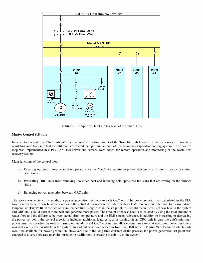
Figure 7. Simplified One Line Diagram of the ORC Units
Master Control Software
In order to integrate the ORC units into the evaporative cooling circuit of the Tosçelik Slab Furnace, it was necessary to provide a regulating loop to ensure that the ORC units extracted the optimum amount of heat from the evaporative cooling system. The control loop was implemented in a PLC. An HMI server and screens were added for remote operation and monitoring of the waste heat recovery system.
Main functions of the control loop:
a) Ensuring optimum resource inlet temperature for the ORCs for maximum power efficiency at different furnace operating conditions
b) Preventing ORC units from removing too much heat and inducing cold spots into the slabs that are resting on the furnace skids.
c) Balancing power generation between ORC units
The above was achieved by sending a power generation set point to each ORC unit. The power setpoint was calculated in the PLC based on available excess heat by comparing the actual drum water temperature with an HMI screen input reference for desired drum temperature (Figure 8). If the actual drum temperature is higher than the set point, this would mean there is excess heat in the system and ORC units could extract more heat and generate more power. The amount of excess heat is calculated by using the total amount of water flow and the difference between actual drum temperature and the HMI screen reference. In addition to increasing or decreasing the power set point, the control algorithm includes additional features such as turning off an ORC unit in case the unit’s minimum power limit was reached as well as turning on an additional ORC unit in case all operating units were at maximum power and there was still excess heat available in the system. In and out of service selection from the HMI screen (Figure 9) determined which units would be available for power generation. However; due to the long time constant of the process, the power generation set point was changed at a very slow rate to avoid introducing oscillations or creating instability in the system.
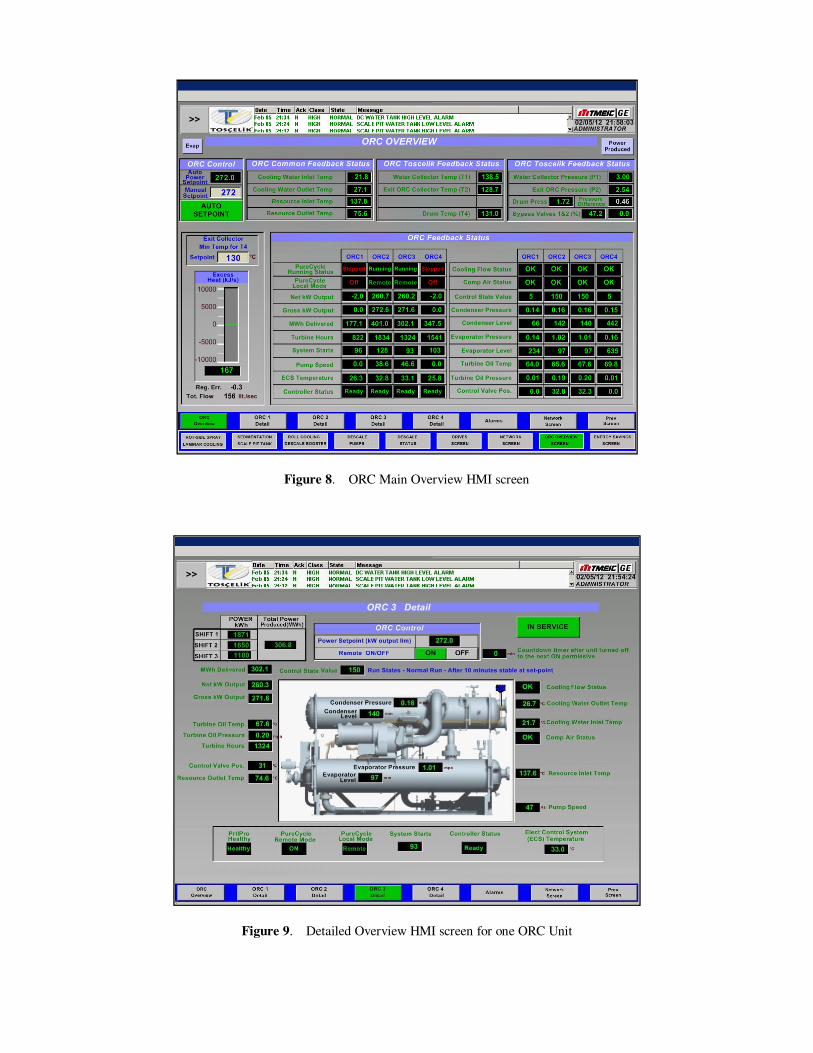
Figure 8. ORC Main Overview HMI screen
Figure 9. Detailed Overview HMI screen for one ORC Unit

All of the critical system parameters were archived in a data collection system that is capable of storing information for several months.
Calculation of power set point for ORC units is represented by the block diagram in Figure 10. The control loop continuously monitors the heat extracted by the ORCs and the available excess heat in the system. Since the hot resource flow for each ORC was not known, a simple look-up table was constructed using ORC datasheet values. This lookup table is shown in Table I. Based on the actual gross power of ORC units, the lookup table is used to estimate the heat consumed. Once the actual heat consumption and the available heat are known, the new heat extraction value is then calculated and using the same lookup table, converted back to the new gross power reference for ORC units.
Figure 10. ORC power set point calculation block diagram
Reference – HMI screen input value for the desired drum temperature
T4 fbk – This represents the actual drum temperature measured at the main circulation pump outlet
Error – Difference between desired and actual drum temperature
Total Flow – Total flow feedback measured after the circulation pump (summation of all ORC units and bypass flow)
Eqn - H = Cp * Mass * ∆T Equation 2
where
H = Heat Flow (kJ/sec)
Cp = Thermal capacity of water = 4.25 kJ/kg˚C at 125C and 0.5MPa
Mass = Total flow in (kg/sec)
∆T = T1-T2 temperature error from the proportional gain regulator (C)
The Heat Flow for each gross kW power set-point for one ORC unit has been added to Table I, by using the Equation 2 above where T1 = 142C stands for ORC resource inlet temperature and T2 is for the ORC outlet temperature
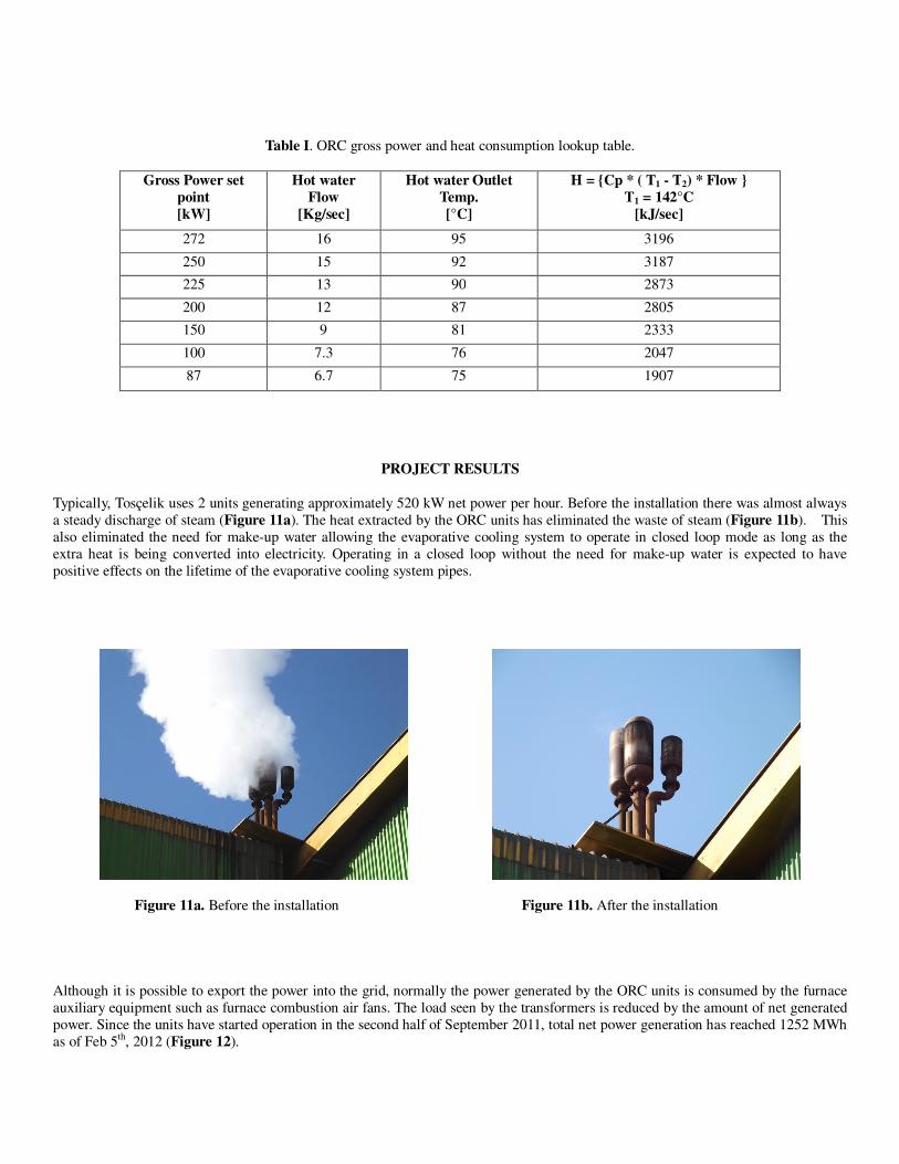
Table I. ORC gross power and heat consumption lookup table.
Gross Power set
point
[kW]
Hot water
Flow
[Kg/sec]
Hot water Outlet
Temp.
[°C]
H = {Cp * ( T1 - T2) * Flow }
T1 = 142°C
[kJ/sec]
272 16 95 3196
250 15 92 3187
225 13 90 2873
200 12 87 2805
150 9 81 2333
100 7.3 76 2047
87 6.7 75 1907
PROJECT RESULTS
Typically, Tosçelik uses 2 units generating approximately 520 kW net power per hour. Before the installation there was almost always a steady discharge of steam (Figure 11a). The heat extracted by the ORC units has eliminated the waste of steam (Figure 11b). This also eliminated the need for make-up water allowing the evaporative cooling system to operate in closed loop mode as long as the extra heat is being converted into electricity. Operating in a closed loop without the need for make-up water is expected to have positive effects on the lifetime of the evaporative cooling system pipes.
Figure 11a. Before the installation Figure 11b. After the installation
Although it is possible to export the power into the grid, normally the power generated by the ORC units is consumed by the furnace auxiliary equipment such as furnace combustion air fans. The load seen by the transformers is reduced by the amount of net generated power. Since the units have started operation in the second half of September 2011, total net power generation has reached 1252 MWh as of Feb 5th, 2012 (Figure 12).
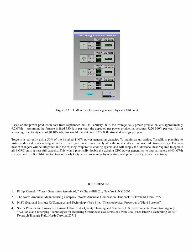
Figure 12. HMI screen for power generated by each ORC unit
Based on the power production data from September 2011 to February 2012, the average daily power production was approximately 9.2MWh. Assuming the furnace is fired 350 days per year, the expected net power production becomes 3220 MWh per year. Using an average electricity cost of $0.10/kWh, this would translate into $322,000 estimated savings per year. Tosçelik is currently using 50% of the installed 1 MW power generation capacity. To maximize utilization, Tosçelik is planning to install additional heat exchangers in the exhaust gas tunnel immediately after the recuperators to recover additional energy. The new heat exchangers will be integrated into the existing evaporative cooling system and will supply the additional heat required to operate all 4 ORC units at near full capacity. This would practically double the existing ORC power generation to approximately 6440 MWh per year and result in 6440 metric tons of yearly CO2 emissions savings by offsetting coal power plant generated electricity.
REFERENCES
1. Philip Kiameh, “Power Generation Handbook,” McGraw-Hill Co., New York, NY, 2003.
2. The North American Manufacturing Company, “North American Combustion Handbook,” Cleveland, Ohio 1965
3. NIST (National Institute Of Standards and Technology) Web Site, “Thermophysical Properties of Fluid Systems”
4. Sector Policies and Programs Division Office of Air Quality Planning and Standards U.S. Environmental Protection Agency, “Available and Emerging Technologies for Reducing Greenhouse Gas Emissions from Coal-Fired Electric Generating Units,” Research Triangle Park, North Carolina 27711