notice concerning copyright restrictionspubs.geothermal-library.org/lib/grc/1029436.pdf · as the...
TRANSCRIPT

NOTICE CONCERNING COPYRIGHT RESTRICTIONS
This document may contain copyrighted materials. These materials have been made available for use in research, teaching, and private study, but may not be used for any commercial purpose. Users may not otherwise copy, reproduce, retransmit, distribute, publish, commercially exploit or otherwise transfer any material.
The copyright law of the United States (Title 17, United States Code) governs the making of photocopies or other reproductions of copyrighted material.
Under certain conditions specified in the law, libraries and archives are authorized to furnish a photocopy or other reproduction. One of these specific conditions is that the photocopy or reproduction is not to be "used for any purpose other than private study, scholarship, or research." If a user makes a request for, or later uses, a photocopy or reproduction for purposes in excess of "fair use," that user may be liable for copyright infringement.
This institution reserves the right to refuse to accept a copying order if, in its judgment, fulfillment of the order would involve violation of copyright law.

GRC Transactions, Vol. 35, 2011
1417
KeywordsDarajat, boron cycling, tracer, injectate-condensate, well con-nectivity, geothermal, vapor dominated
ABSTRACT
Long-term sustainability of a vapor-dominated geothermal resource is largely determined by the injection of fluids back into the reservoir. Properly managed, injection generates “new steam” as the water boils when it comes into contact with hot dry rock in the reservoir. Without injection the field would dry out and production would go into decline. For the development of a long term injection strategy, two studies have been performed, a 2008 tracer test and a review of boron cycling, which aims to understand the connection between injection and production wells.
This paper compares the boron cycling process and tracer migration at Darajat Field. Cycling of boron in liquid condensate-injectate is then fractionated as boron in the steam phase between the DRJ-03 injector and surrounding production wells. Recovery of volatile tracers injected into the DRJ-03 injector is compared. In general, production wells with high boron content in steam have tracer recovered from the same injection well.
1. Introduction
Darajat is the largest producing vapor dominated geothermal field in Indonesia. It is located near Garut City, West Java Province, Indonesia about 150 km southeast of Jakarta (Figure 1). Darajat currently has 3 power plants (Units I/II/III) that generate a total of 260 MW of electricity to Java Island. Unit-I generates 55 MW and is operated by PT. Indonesia Power. Unit-II/III generates 95 MW and 110 MW, respectively, are operated by Chevron Geo-thermal Indonesia.
The field lies within the Kendang volcanic complex, one of many volcanoes in the volcanic arc that extends from the northern tip of Sumatra, through Java, and eastward through the Banda Arc. The Kendang volcanic complex is part of a Quaternary volcanic range, extending from Papandayan volcano in the southwest
to the Guntur volcano in the northeast. The exploration of this field started on 1984 and the generation of the electricity began in 1994. Currently, the Darajat field has 23 production wells that supply steam to the power plants, 4 injection wells, and 6 monitoring wells.
Properly managed reinjection generates “new steam” as the injectate boils in the reservoir, hence maintaining reservoir pres-sure and increase energy extraction efficiency over the life on the reservoir. Reinjection of plant condensate should reduce the potential early reservoir dry out and field wide rapid production decline. However, inappropriate placement of injection wells, injection rate and duration of injection, can lead to premature breakthrough, reservoir cooling or waste the injected water. These phenomenon provide setbacks to the goal of enhancing energy extraction. In addition, injection breakthrough could result in operational problems, such as derating of plant output, scale development, additional costs for makeup wells and modification to surface facilities.
Two types of simultaneously-performed studies, a tracer test and steam-liquid boron measurements have been performed in order to understand the connection between liquid injection and
The Comparison of Boron Cycling and Tracer Test Result at Darajat Geothermal Field and Its Usefulness
for Production and Injection Management
Abu Dawud H, Jeffrey Roberts, Arias Sugandhi, Junior Setiawan, and Philip Molling
Chevron Geothermal and Power, Sentral Senayan II, Jakarta, [email protected], [email protected], [email protected],
[email protected], [email protected]
Figure 1. Location of the Darajat geothermal field in relation to other cit-ies in Java island.

1418
Duwad, et al..
steam production. Connectivity controls the time of thermal break-through and rate of cooling of production wells. Tracer testing has been performed three times in Darajat during 1998, 2001, and 2008, each with a different purpose. Meanwhile, historical boron cycling in Darajat was recently evaluated in 2008 and integrated with bottom-hole superheat and non-condensable gas (NCG) data.
2. Boron Cycling at Darajat Field
Boron is a conservative element that prefers to exist as a dis-solved species in the liquid. Equilibrium fractionation (i.e., log B value) of boron into the steam and liquid was first addressed in Glover (1988) by the following equations:
1KD
=BlBv
10 3.0506-0.00669t⎡⎣ ⎤⎦ , for 150-320oC (1)
ort oC( ) = 456+149.5logKD (2)
where t, KD, Bl, Bv are separation temperature, equilibrium ratio of the boron concentration in the steam to that in the water, con-centration of boron in liquid and concentration of boron in vapor, respectively.
With this theoretical background, the evolu-tion of boron (B) in steam can give insight into the migration and boiling history of the condensate-injectate at the Darajat Geothermal Field. Table 1 shows the historical fieldwide average boron content of both steam (production wells) and
liquid (injection wells). Both boron content in fieldwide steam and injected liquid increased through time which confirms the cycling process of boron from injection well to production wells.
In addition to the fieldwide boron increase in steam, the area that has greater than 10 ppmw boron content in steam expanded from 1998 until 2008 which is shown in Figure 2.
Boron concentration of DRJ-03 condensate injectate has increased significantly faster than DRJ-15 condensate injectate which is shown in Figure 3. DRJ-03 supplies more boron to the steam for two reasons: (1) the concentration in the injectate is higher and (2) its liquid is injected into the portion of the field with highest production rates and has had the longest period of extrac-tion. Higher extraction rates and prolonged production lowers the reservoir pressure and allows more boiling of liquid injectate. The higher steam boron content also suggests that the boron cycling process is occurring between DRJ-03 and surrounding production wells, as opposed to the other injectors.
3. Tracer Tests at Darajat Field
The first tracer test at Darajat was conducted in 1998. The main objective of this test was to evaluate well connectivity and identify short term impacts of infield injection near the Gagak fault. Two vapor tracers were utilized, sulfur hexafluoride (SF6) and Freon R-134a, they were injected into DRJ-7, a well at the center of the field. Among twelve production wells that were used as target wells, tracer returns were detected in five wells. The recovery of R-134a was 54%, whereas SF6 recovery was relatively small (0.3%). Given that SF6 was co-injected into the same well with the R-134a, we assume the SF6 rapidly degraded or was adsorbed in the reservoir. The results showed that tracer moved very quickly within the reservoir, at rates on the order of meters per hour or tens to hundreds of meters per day.
The second tracer test was performed in 2001, utilizing two active reinjection wells in the field, DRJ-3 and DRJ-15, which received condensate from Unit-I (55 MW) and Unit-II (95 MW). The main objectives of the test were to determine the effectiveness of injection into the two wells in increasing steam production and to determine any liquid injection breakthrough. A simultaneous
Table 1. Historical data of boron content both at steam and liquid on average in Darajat.
Figure 2. Boron distribution map above 10 ppmw of Darajat Geothermal Field from 1998 - 2008.
Figure 3. Historical Trend of Boron Content in Condensate Injectate at Darajat Geothermal Field.
1419
Duwad, et al..
tracer injection using vapor-phase tracers (R-134a & R-23) and liquid-phase tracers (1,5- and 2,7 Naphthalene Disulfonic Acid – NDSA) were injected into the two wells. It was expected that the results of the two separate tracers would give different aspects of the movement and thermodynamics of the injected water through the analysis of the behavior of boiled injectate and its role in enhancing steam production.
A total of 13 wells were monitored for tracer returns. The R-134a was detected in 5 wells, whereas R-23 that was injected into DRJ-15 was not detected in any of the monitored wells. The two liquid tracers were also not recovered and this was interpreted as an indication of no liquid breakthrough in production wells.
The recent tracer test was initiated on December 4, 2008, ap-proximately 5 months after Darajat field commenced injecting into the new injection well, DRJ-12. DRJ-12 was targeted to the area of highest superheat. In addition to refinement of the connectivity between injection and newly drilled production wells, this tracer test was also expected to quantify the volume of injected water that was being boiled in the reservoir and produced by the sur-rounding steam production wells. After a comprehensive review of the potential long term benefits to injection strategy, it was concluded that a multi-well vapor and two-phase tracer test was the best approach.
4. The Comparison between Boron Cycling and Tracer Test Results
High boron content of steam in a production well indicates that the boiling of migrating injectate-condensate liquid into produc-tion well is relatively high. It also suggests that the production well has connectivity with the injection well. Historical review of boron indicates that a cycling process of boron occurs between DRJ-03 and surrounding wells that have high boron content in their steam. Therefore, the comparison of both studies will focus on boron cycling at DRJ-03 and DRJ-03 tracer response.
In order to understand the effect of boron cycling at produc-tion wells, the historical boron content of several production wells located close to DRJ-03 were evaluated. Six production wells with historically have high boron content are shown in figure 4.
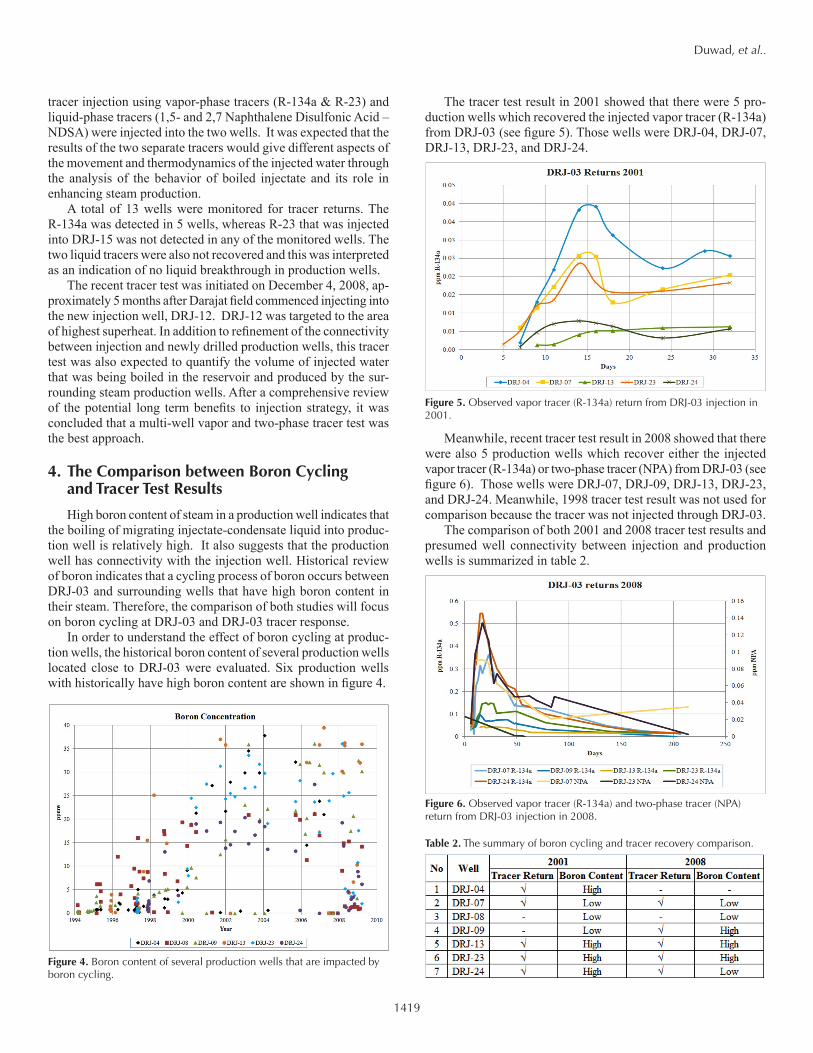
The tracer test result in 2001 showed that there were 5 pro-duction wells which recovered the injected vapor tracer (R-134a) from DRJ-03 (see figure 5). Those wells were DRJ-04, DRJ-07, DRJ-13, DRJ-23, and DRJ-24.
Meanwhile, recent tracer test result in 2008 showed that there were also 5 production wells which recover either the injected vapor tracer (R-134a) or two-phase tracer (NPA) from DRJ-03 (see figure 6). Those wells were DRJ-07, DRJ-09, DRJ-13, DRJ-23, and DRJ-24. Meanwhile, 1998 tracer test result was not used for comparison because the tracer was not injected through DRJ-03.
The comparison of both 2001 and 2008 tracer test results and presumed well connectivity between injection and production wells is summarized in table 2.
Figure 4. Boron content of several production wells that are impacted by boron cycling.
Figure 5. Observed vapor tracer (R-134a) return from DRJ-03 injection in 2001.
Figure 6. Observed vapor tracer (R-134a) and two-phase tracer (NPA) return from DRJ-03 injection in 2008.
Table 2. The summary of boron cycling and tracer recovery comparison.

1420
Duwad, et al..
There are 5 of 7 wells that show consistent result between DRJ-03 tracer returns and high boron steam content. Wells DRJ-08 and DRJ-09 with low boron content do not recover the tracer from DRJ-03 in 2001. A different result is shown by DRJ-07 and DRJ-24 where these wells had low boron content but recovered tracer from DRJ-03: DRJ-07 in 2001 and 2008, and DRJ-24 in 2008. Lower amounts of boiling of liquid injectate best explain this inconsistency.
4.1 DRJ-04 Boron Cycling vs. Tracer TestDRJ-04 is one of the production wells that supply steam to
Unit-1 power plant. This well started delivering steam to power plant in 1995, but unfortunately this well was abandoned in early 2008 due to casing integrity problem. Figure 7 shows boron con-tent history of this well.
During early production, the boron content was relatively low (below 5 ppmw) and then increased significantly from 2000 (20 ppmw) to 2006 (35ppmw). Finally, the boron content in steam decreased to between 15 and 25ppmw in 2006 and 2007. This well recovered tracer from the 2001 DRJ-03 tracer test consistent with the high boron content during the same year. Figure 8 shows DRJ-04 tracer recovery from DRJ-03 in 2001 tracer test. During the 2008 tracer test is DRJ-04 had already been abandoned.
4.2 DRJ-07 Boron Cycling vs Tracer TestDRJ-07 is also one of the production wells that has been sup-
plying steam to Unit-1 power plant since 1995. This well had a relatively low boron content (below 5 ppmw) during its production period. Figure 10 shows the boron content history of this well.
Figure 9. DRJ-07 boron content history.
This well recovered tracer from DRJ-03 in both the 2001 and 2008 tracer tests (see figure 10 and figure 11), which is inconsis-tent with low boron content in the same year. This inconsistent correlation indicates that the injectate condensate from DRJ-03 migrates to DRJ-07, but the injectate that arrives at DRJ-07 has not boiled significantly, so that the steam contains a low boron content.
Figure 7. DRJ-04 boron content history.
Figure 8. DRJ-04 tracer recovery from DRJ-03 in 2001 tracer test. Figure 11. DRJ-07 tracer recovery from DRJ-03 in 2008 tracer test.
Figure 10. DRJ-07 tracer recovery from DRJ-03 in 2001 tracer test.

1421
Duwad, et al..
4.3 DRJ-08 Boron Cycling vs Tracer TestDRJ-08 is one of the production wells that has been supplying
steam to Unit-1 power plant since 1995. In general, this well had a high boron content since early production, as shown by figure 12. However, during the tracer test periods in 2001 and 2008 the boron content was low which is consistent with no tracer recovery from DRJ-03.
Figure 12. DRJ-08 boron content history.
4.4 DRJ-09 Boron Cycling vs Tracer Test
DRJ-09 is one of the production wells that has been producing since 1995. This well is able to deliver steam either to Unit-1 or Unit-2/3 power plant, but usually delivers steam to Unit-1. Figure 13 shows the boron content history of this well where initially the boron content of this well was relatively low then gradually increased until it reached high boron content (around 35 ppmw) in 2008.
Figure 13. DRJ-09 boron content history.
This well did not recover tracer from DRJ-03 in the 2001 tracer test, while in the 2008 tracer test this well recovered tracer from DRJ-03. Figure 14 shows DRJ-09 tracer recovery from DRJ-03 in 2008. The lower boron content in 2001 (around 10 ppmw)
and high boron content in 2008 (around 32 ppmw) is somewhat consistent with the relative tracer recovery.
Figure 14. DRJ-09 tracer recovery from DRJ-03 in 2008 tracer test.
4.5 DRJ-13 Boron Cycling vs Tracer Test
DRJ-13 is one of the production wells that has been delivering steam to Unit-1 power plant since 1997. The boron content of this well increased significantly in the early production until reaching a high (around 35 ppmw) in 2001 then stabilized until 2008. Figure 15 shows the boron content history of this well.
Figure 15. DRJ-13 boron content history.
This well recovered tracer from DRJ-03 in both 2001 and 2008 tracer test consistent with the historically high boron content. Figures 16 and 17 show the DRJ-13 tracer recovery from DRJ-03 in 2001 and 2008, respectively.
4.6 DRJ-23 Boron Cycling vs Tracer TestDRJ-23 is one of the production wells that has been delivering
steam to Unit-2/3 power plant since 2000. The boron content of this well increased significantly from the early production level until it reached 25 ppmw then it was stable until 2008. Figure 18 shows the boron content history of this well.

1422
Duwad, et al..
This well recovered tracer from DRJ-03 in both 2001 and 2008 tracer test consistently with its historically high boron content. Figure 19 and figure 20 show the DRJ-23 tracer recovery from DRJ-03 in 2001 and 2008, respectively.
4.7 DRJ-24 Boron Cycling vs Tracer TestDRJ-24 is one of the production wells that has been delivering
steam to Unit-2/3 power plant since 1999. The boron content of this well increased rapidly to 20 ppmw in 2000. This well was temporarily shut-in from 2006 until mid of 2008. Figure 21 shows the boron content history of DRJ-24.
Figure 16. DRJ-13 tracer recovery from DRJ-03 in 2001 tracer test.
Figure 17. DRJ-13 tracer recovery from DRJ-03 in 2008.
Figure 18. DRJ-23 boron content history.
Figure 19. DRJ-23 tracer recovery from DRJ-03 in 2001.
Figure 20. DRJ-23 tracer recovery from DRJ-03 in 2008.
Figure 21. DRJ-24 boron content history.

1423
Duwad, et al..
This well recovered tracer from DRJ-03 both in 2001 (figure 22) and 2008 (figure 23) tracer test which is consistent with high boron content in 2001 and inconsistent with low boron content in 2008. Low boron content in 2008 indicates a low boiling of liquid injectate-condensate possibly due to operational procedures, such as intermittent use after a shut-in period.
5. SummaryMost of the production wells that were used for comparison
show a consistency between high boron in steam and tracer
recovery. So that, in general, the process of boron cycling and tracer-determined connectivity appears to match. Wells that had low boron content did not recover the tracer. Two wells had low boron, but had some tracer recovery. This apparent inconsistency is best explained as a lower boiling rate of the liquid injectate arriving at these wells.
The comparison of both studies concludes that wells having high boron content always recover the tracer while wells having low boron content may recover the tracer. The combination of tracer recovery and high boron content at a given well means that the injectate-condensate has migrated to this well and has flashed into steam due to high boiling activity that has occurred at this well. On the other hand, recovery of tracer from a well with a low boron content means that injectate-condensate has migrated to this well but flashes into steam at a low rate.
Finally, the most important information that was obtained from this comparison is that boron is able to behave as a natural tracer if boiling activity (indicated by high boron content) occurs in production wells. Implementation of boron as a tracer for iden-tifying the connectivity between injection and production wells will be useful in field management.
Acknowledgement
We thank Chevron Geothermal Indonesia (CGI) for supporting this project and granting permission to publish this paper.
References
Glover, 1988, Boron distribution between liquid and vapour in geothermal flu-ids: Proceedings, 10th New Zealand Geothermal Workshop, 1988, pp. 6.
Mahagyo, P., Roberts, J.W., Sugandhi, A., and Molling, P., 2010, Review of baseline geochemical model and the impact of production at the Darajat Geothermal Field, Indonesia, World Geothermal Congress Paper, April 25-29, 2010, pp 5.
Hidayaturrobi, A.D., Roberts, J.W., Sugandhi, A., Mahagyo, P., and Molling, P., 2010, The role of boron cycling and superheat monitoring for field production and injection strategies at the Darajat Geothermal Field, Garut, Indonesia, World Geothermal Congress Paper, April 25-29, 2010.
Sugandhi, A., Hirtz, P.N., Mahagyo, P., Nordquist, G.A., Martiady, K., Roberts, J.W., Kunzman, R.J., Adams, M.C., 2009, Result of the first application perfluorocarbons and alcohols in a multi-well vapor and two-phase tracer at the Darajat Geothermal Field, Indonesia, and implications for injection management.
Figure 22. DRJ-24 tracer recovery from DRJ-03 in 2001 tracer test.
Figure 23. DRJ-24 tracer recovery from DRJ-03 in 2008 tracer test.

1424