non-isolated high gain dc-dc converters for fuel cell...
TRANSCRIPT
Non-Isolated High Gain DC-DC Converters for Fuel Cell Application – A Comparative StudyDivya Navamani.J*, Vijayakumar.K* and Lavanya.A*
Abstract: This paper evaluates different topologies of non-isolated high gain DC-DC converter for fuel cell application. These converters transmit the low dc voltage of fuel cell to high dc voltage in DC link. In this learning, ripple content of both input current and output voltage were evaluated and discussed. In addition to that current and voltage stress are computed and compared. A comparison and discussion of the efficiency and losses are also presented in this paper. Study conceded out on this paper intends to choose the most excellent converter for fuel cell application. The selected converter has high conversion ratio, reduced voltage and current stresses on the power semiconductor switches when contrasted to the conventional boost converter. The analyzed converter can be applied to fuel cell system and also other renewable energy systems. Simulation is conducted over MATLAB/Simulink.
Keyword: Fuel cell, High gain, DC-DC converter, Ripples, Voltage and current stress.
1. INTRODUCTIONIn the present day, energy catastrophe is due to the raise in demand. As a result, the utilization of non-renewable resources is also increased. This lead to the acceptance of renewable resources. Among them, hybrid vehicles is a promising technology. The hybrid vehicles use storage batteries for the locomotive purpose. Fuel cells are extensively being used nowadays as a source for the hybrid vehicle. A fuel cell is a device that employs hydrogen and oxygen to create electricity. These are more energy efficient than combustion engine and the hydrogen used to power them can drawn from variety of sources.
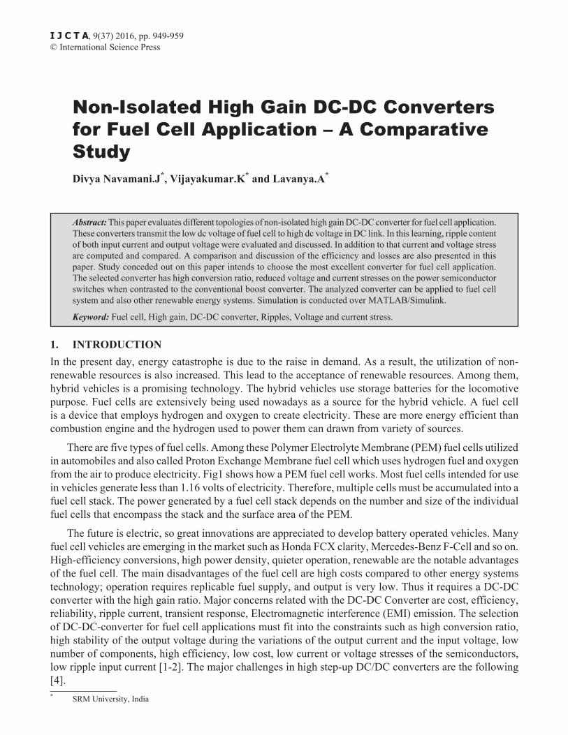
There are five types of fuel cells. Among these Polymer Electrolyte Membrane (PEM) fuel cells utilized in automobiles and also called Proton Exchange Membrane fuel cell which uses hydrogen fuel and oxygen from the air to produce electricity. Fig1 shows how a PEM fuel cell works. Most fuel cells intended for use in vehicles generate less than 1.16 volts of electricity. Therefore, multiple cells must be accumulated into a fuel cell stack. The power generated by a fuel cell stack depends on the number and size of the individual fuel cells that encompass the stack and the surface area of the PEM.
The future is electric, so great innovations are appreciated to develop battery operated vehicles. Many fuel cell vehicles are emerging in the market such as Honda FCX clarity, Mercedes-Benz F-Cell and so on. High-efficiency conversions, high power density, quieter operation, renewable are the notable advantages of the fuel cell. The main disadvantages of the fuel cell are high costs compared to other energy systems technology; operation requires replicable fuel supply, and output is very low. Thus it requires a DC-DC converter with the high gain ratio. Major concerns related with the DC-DC Converter are cost, efficiency, reliability, ripple current, transient response, Electromagnetic interference (EMI) emission. The selection of DC-DC-converter for fuel cell applications must fit into the constraints such as high conversion ratio, high stability of the output voltage during the variations of the output current and the input voltage, low number of components, high efficiency, low cost, low current or voltage stresses of the semiconductors, low ripple input current [1-2]. The major challenges in high step-up DC/DC converters are the following [4].* SRM University, India
I J C T A, 9(37) 2016, pp. 949-959© International Science Press
950 Divya Navamani.J, Vijayakumar.K and Lavanya.A
Figure 1: Fuel cell stack
• To widen the voltage gain and also evade the extreme duty cycle to reduce the conduction losses.
• To lessen the switch voltage to make use of low voltage MOSFETs.
• To realize soft switching to diminish the switching losses.
• To alleviate the output diode reverse-recovery problem.
• To boost the power level easily and reduce the passive component dimension.
The first hinders are taken, and they were examined to choose the finest converter for the fuel cell. Especially designing a converter with an inductor in series with the input and interleaved topology is essential for the fuel cell application system. Hence this paper is mainly based on the ripple analysis of input current of the different converter employed for the fuel cell application system.
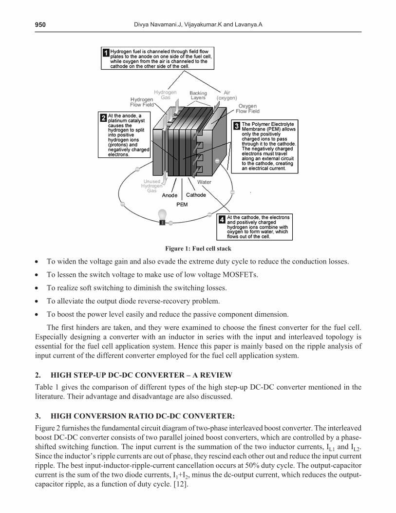
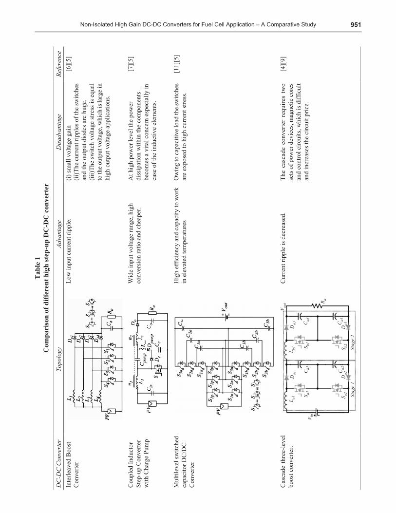
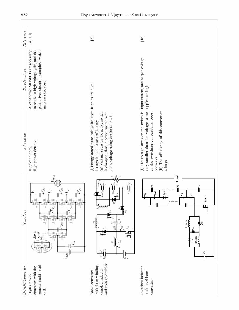
2. HIGH STEP-UP DC-DC CONVERTER – A REVIEWTable 1 gives the comparison of different types of the high step-up DC-DC converter mentioned in the literature. Their advantage and disadvantage are also discussed.
3. HIGH CONVERSION RATIO DC-DC CONVERTER:Figure 2 furnishes the fundamental circuit diagram of two-phase interleaved boost converter. The interleaved boost DC-DC converter consists of two parallel joined boost converters, which are controlled by a phase-shifted switching function. The input current is the summation of the two inductor currents, IL1 and IL2. Since the inductor’s ripple currents are out of phase, they rescind each other out and reduce the input current ripple. The best input-inductor-ripple-current cancellation occurs at 50% duty cycle. The output-capacitor current is the sum of the two diode currents, I1+I2, minus the dc-output current, which reduces the output-capacitor ripple, as a function of duty cycle. [12].
951Non-Isolated High Gain DC-DC Converters for Fuel Cell Application – A Comparative Study
Tab
le 1
C
ompa
riso
n of
diff
eren
t hig
h st
ep-u
p D
C-D
C c
onve
rter
DC
-DC
Con
vert
erTo
polo
gyAd
vant
age
Dis
adva
ntag
eRe
fere
nce
Inte
rleav
ed B
oost
C
onve
rter
Low
inpu
t cur
rent
ripp
le.
(i) sm
all v
olta
ge g
ain
(ii)T
he c
urre
nt ri
pple
s of t
he sw
itche
s an
d th
e ou
tput
dio
des a
re h
uge.
(iii)T
he sw
itch
volta
ge st
ress
is e
qual
to
the o
utpu
t vol
tage
, whi
ch is
larg
e in
high
out
put v
olta
ge a
pplic
atio
ns.
[6][
5]
Cou
pled
Indu
ctor
St
ep-u
p C
onve
rter
with
Cha
rge
Pum
p
Wid
e in
put v
olta
ge ra
nge,
hig
h co
nver
sion
ratio
and
che
aper
.A
t hig
h po
wer
leve
l the
pow
er
diss
ipat
ion
with
in th
e co
mpo
nent
s be
com
es a
vita
l con
cern
esp
ecia
lly in
ca
se o
f the
indu
ctiv
e el
emen
ts.
[7][
5]
Mul
tilev
el sw
itche
d ca
paci
tor D
C/D
C
Con
verte
r
Hig
h ef
ficie
ncy
and
capa
city
to w
ork
in e
leva
ted
tem
pera
ture
sO
win
g to
capa
citiv
e loa
d th
e sw
itche
s ar
e ex
pose
d to
hig
h cu
rren
t stre
ss.
[11]
[5]
Cas
cade
thr
ee-le
vel
boos
t con
verte
r.C
urre
nt ri
pple
is d
ecre
ased
.Th
e ca
scad
e co
nver
ter
requ
ires
two
sets
of p
ower
dev
ices
, mag
netic
cor
es
and
cont
rol c
ircui
ts, w
hich
is d
iffic
ult
and
incr
ease
s the
circ
uit p
rice.
[4][
9]
952 Divya Navamani.J, Vijayakumar.K and Lavanya.A
DC
-DC
Con
vert
erTo
polo
gyAd
vant
age
Dis
adva
ntag
eRe
fere
nce
Hig
h st
ep-u
p co
nver
ter w
ith th
e ge
nera
l mul
ti-le
vel
cell.
Hig
h ef
ficie
ncy,
Hig
h po
wer
den
sity
A
lot o
f pow
er M
OSF
ETs a
re ne
cess
ary
to re
aliz
e a
high
vol
tage
gai
n, a
nd th
e ga
te d
river
circ
uit i
s co
mpl
ex, w
hich
in
crea
ses t
he c
ost.
[4][
10]
Boo
st c
onve
rter
with
thre
e w
indi
ng
coup
led
indu
ctor
an
d vo
ltage
dou
bler
(i) E
nerg
y sto
red
in th
e lea
kage
indu
ctor
is
recy
cled
to in
crea
se e
ffic
ienc
y(ii
) Vol
tage
stre
ss o
n th
e ac
tive
switc
h is
cla
mpe
d; th
us, a
pow
er s
witc
h w
ith
a lo
w v
olta
ge ra
ting
can
be a
dopt
ed.
Rip
ples
are
hig
h[8
]
Switc
hed
indu
ctor
m
ultil
evel
boo
st
conv
erte
r
(i) T
he v
olta
ge s
tress
on
the
switc
h is
ve
ry s
mal
ler
than
the
vol
tage
stre
ss
on t
he s
witc
hing
con
vent
iona
l bo
ost
conv
erte
r(ii
) Th
e ef
ficie
ncy
of t
his
conv
erte
r is
larg
e
Inpu
t cur
rent
, and
out
put v
olta
ge
rippl
es a
re h
igh
[16]
953Non-Isolated High Gain DC-DC Converters for Fuel Cell Application – A Comparative Study
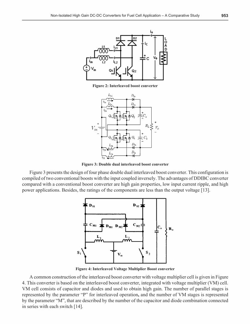
Figure 2: Interleaved boost converter
Figure 3: Double dual interleaved boost converter
Figure 3 presents the design of four phase double dual interleaved boost converter. This configuration is compiled of two conventional boosts with the input coupled inversely. The advantages of DDIBC converter compared with a conventional boost converter are high gain properties, low input current ripple, and high power applications. Besides, the ratings of the components are less than the output voltage [13].
Figure 4: Interleaved Voltage Multiplier Boost converter
A common construction of the interleaved boost converter with voltage multiplier cell is given in Figure 4. This converter is based on the interleaved boost converter, integrated with voltage multiplier (VM) cell. VM cell consists of capacitor and diodes and used to obtain high gain. The number of parallel stages is represented by the parameter “P” for interleaved operation, and the number of VM stages is represented by the parameter “M”, that are described by the number of the capacitor and diode combination connected in series with each switch [14].
954 Divya Navamani.J, Vijayakumar.K and Lavanya.A
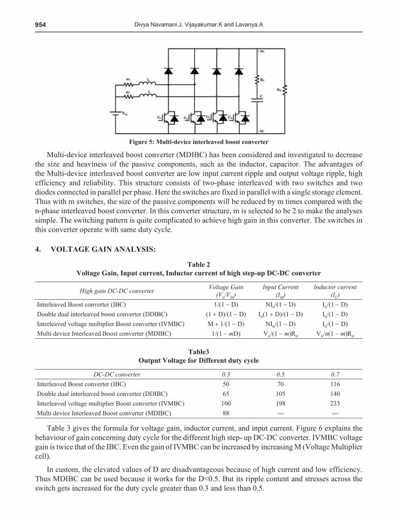
Figure 5: Multi-device interleaved boost converter
Multi-device interleaved boost converter (MDIBC) has been considered and investigated to decrease the size and heaviness of the passive components, such as the inductor, capacitor. The advantages of the Multi-device interleaved boost converter are low input current ripple and output voltage ripple, high efficiency and reliability. This structure consists of two-phase interleaved with two switches and two diodes connected in parallel per phase. Here the switches are fixed in parallel with a single storage element. Thus with m switches, the size of the passive components will be reduced by m times compared with the n-phase interleaved boost converter. In this converter structure, m is selected to be 2 to make the analyses simple. The switching pattern is quite complicated to achieve high gain in this converter. The switches in this converter operate with same duty cycle.
4. VOLTAGE GAIN ANALYSIS:
Table 2 Voltage Gain, Input current, Inductor current of high step-up DC-DC converter
High gain DC-DC converter Voltage Gain (Vo/Vin)
Input Current (Iin)
Inductor current (IL)
Interleaved Boost converter (IBC) 1/(1 - D) NIo/(1 - D) Io/(1 - D)Double dual interleaved boost converter (DDIBC) (1 + D)/(1 - D) Io(1 + D)/(1 - D) Io/(1 - D)Interleaved voltage multiplier Boost converter (IVMBC) M + 1/(1 - D) NIo/(1 - D) Io/(1 - D)Multi device Interleaved Boost converter (MDIBC) 1/(1 - mD) Vo/(1 - m)Ro Vo/n(1 - m)Ro
Table3 Output Voltage for Different duty cycle
DC-DC converter 0.3 0.5 0.7Interleaved Boost converter (IBC) 50 70 116Double dual interleaved boost converter (DDIBC) 65 105 140Interleaved voltage multiplier Boost converter (IVMBC) 100 198 233Multi device Interleaved Boost converter (MDIBC) 88 --- ---
Table 3 gives the formula for voltage gain, inductor current, and input current. Figure 6 explains the behaviour of gain concerning duty cycle for the different high step- up DC-DC converter. IVMBC voltage gain is twice that of the IBC. Even the gain of IVMBC can be increased by increasing M (Voltage Multiplier cell).
In custom, the elevated values of D are disadvantageous because of high current and low efficiency. Thus MDIBC can be used because it works for the D<0.5. But its ripple content and stresses across the switch gets increased for the duty cycle greater than 0.3 and less than 0.5.
955Non-Isolated High Gain DC-DC Converters for Fuel Cell Application – A Comparative Study
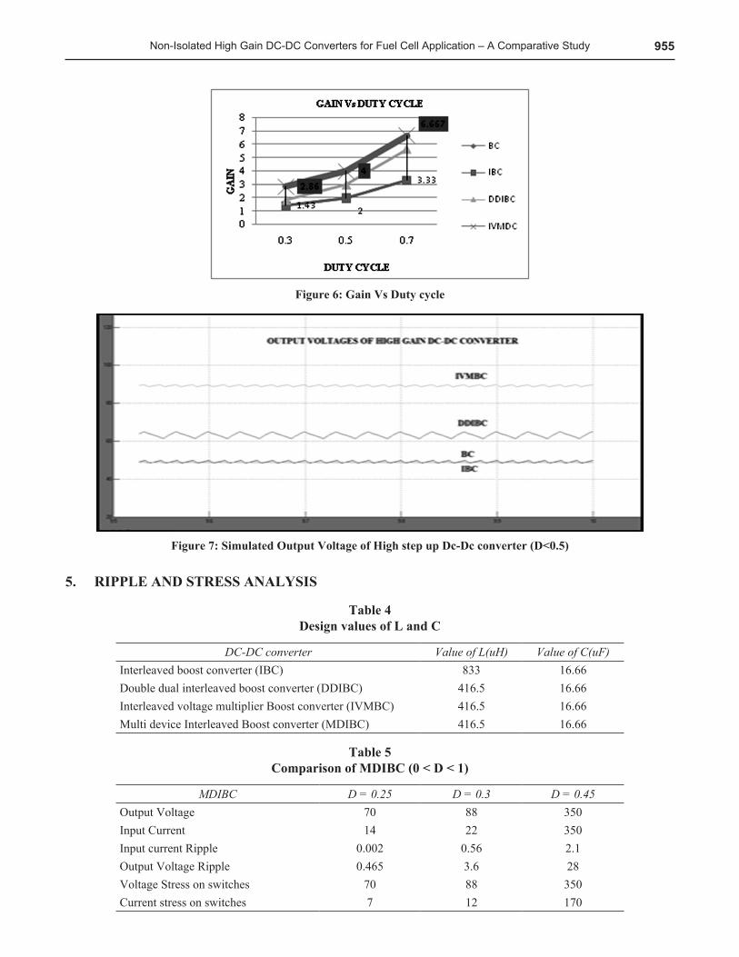
Figure 6: Gain Vs Duty cycle
Figure 7: Simulated Output Voltage of High step up Dc-Dc converter (D<0.5)
5. RIPPLE AND STRESS ANALYSIS
Table 4 Design values of L and C
DC-DC converter Value of L(uH) Value of C(uF)Interleaved boost converter (IBC) 833 16.66Double dual interleaved boost converter (DDIBC) 416.5 16.66Interleaved voltage multiplier Boost converter (IVMBC) 416.5 16.66Multi device Interleaved Boost converter (MDIBC) 416.5 16.66
Table 5 Comparison of MDIBC (0 < D < 1)
MDIBC D = 0.25 D = 0.3 D = 0.45Output Voltage 70 88 350Input Current 14 22 350Input current Ripple 0.002 0.56 2.1Output Voltage Ripple 0.465 3.6 28Voltage Stress on switches 70 88 350Current stress on switches 7 12 170
956 Divya Navamani.J, Vijayakumar.K and Lavanya.A
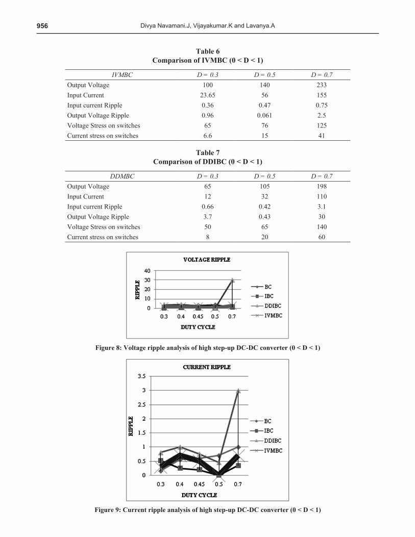
Table 6 Comparison of IVMBC (0 < D < 1)
IVMBC D = 0.3 D = 0.5 D = 0.7Output Voltage 100 140 233Input Current 23.65 56 155Input current Ripple 0.36 0.47 0.75Output Voltage Ripple 0.96 0.061 2.5Voltage Stress on switches 65 76 125Current stress on switches 6.6 15 41
Table 7 Comparison of DDIBC (0 < D < 1)
DDMBC D = 0.3 D = 0.5 D = 0.7Output Voltage 65 105 198Input Current 12 32 110Input current Ripple 0.66 0.42 3.1Output Voltage Ripple 3.7 0.43 30Voltage Stress on switches 50 65 140Current stress on switches 8 20 60
Figure 8: Voltage ripple analysis of high step-up DC-DC converter (0 < D < 1)
Figure 9: Current ripple analysis of high step-up DC-DC converter (0 < D < 1)
957Non-Isolated High Gain DC-DC Converters for Fuel Cell Application – A Comparative Study
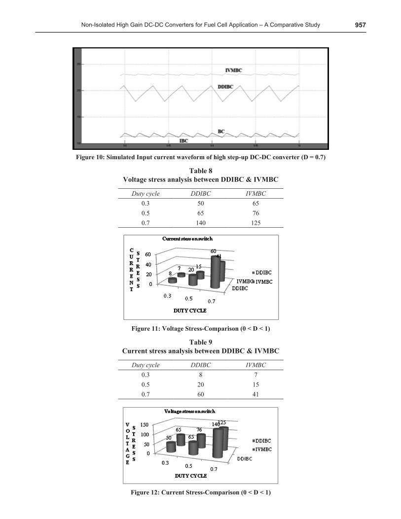
Figure 10: Simulated Input current waveform of high step-up DC-DC converter (D = 0.7)
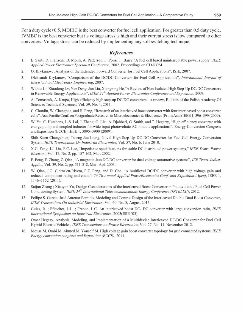
Table 8 Voltage stress analysis between DDIBC & IVMBC
Duty cycle DDIBC IVMBC0.3 50 650.5 65 760.7 140 125
Figure 11: Voltage Stress-Comparison (0 < D < 1)
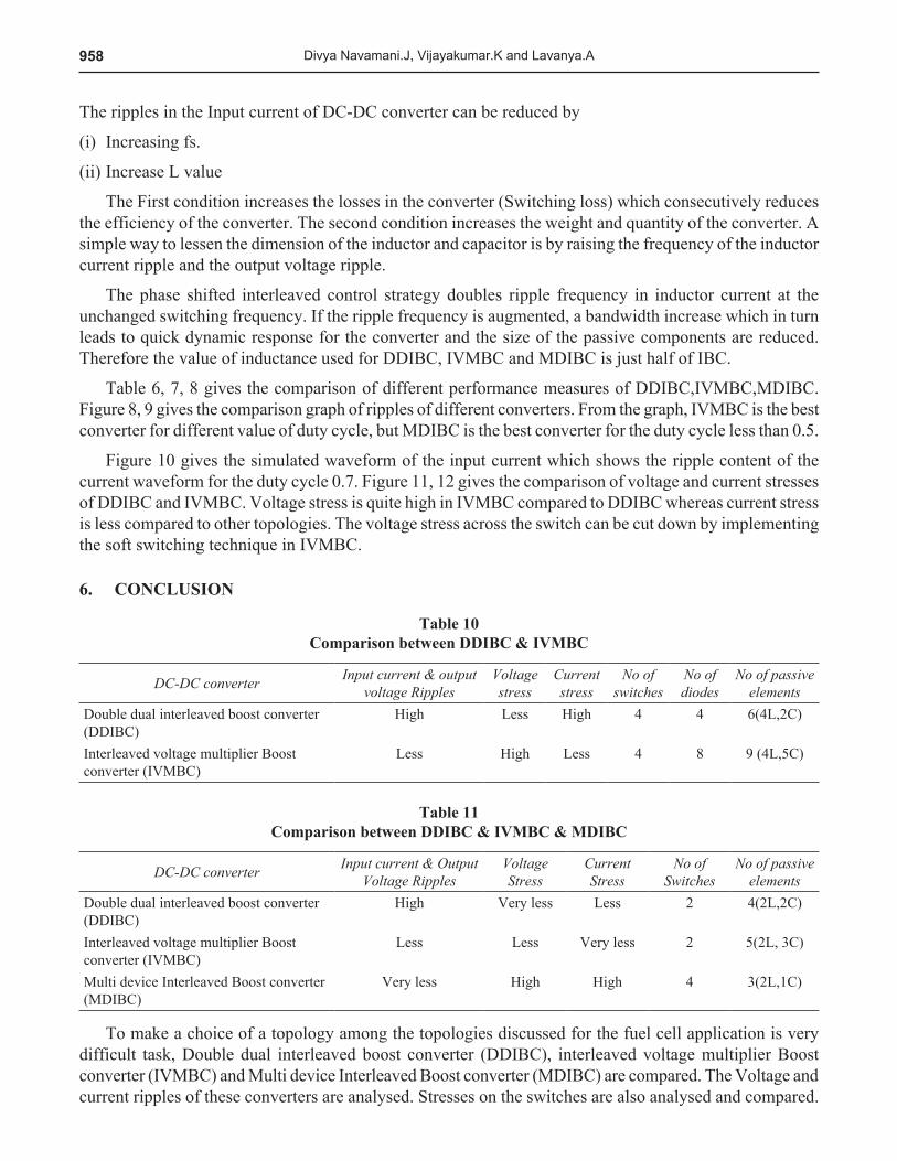
Table 9 Current stress analysis between DDIBC & IVMBC
Duty cycle DDIBC IVMBC0.3 8 70.5 20 150.7 60 41
Figure 12: Current Stress-Comparison (0 < D < 1)
958 Divya Navamani.J, Vijayakumar.K and Lavanya.A
The ripples in the Input current of DC-DC converter can be reduced by
(i) Increasing fs.
(ii) Increase L value
The First condition increases the losses in the converter (Switching loss) which consecutively reduces the efficiency of the converter. The second condition increases the weight and quantity of the converter. A simple way to lessen the dimension of the inductor and capacitor is by raising the frequency of the inductor current ripple and the output voltage ripple.
The phase shifted interleaved control strategy doubles ripple frequency in inductor current at the unchanged switching frequency. If the ripple frequency is augmented, a bandwidth increase which in turn leads to quick dynamic response for the converter and the size of the passive components are reduced. Therefore the value of inductance used for DDIBC, IVMBC and MDIBC is just half of IBC.
Table 6, 7, 8 gives the comparison of different performance measures of DDIBC,IVMBC,MDIBC. Figure 8, 9 gives the comparison graph of ripples of different converters. From the graph, IVMBC is the best converter for different value of duty cycle, but MDIBC is the best converter for the duty cycle less than 0.5.
Figure 10 gives the simulated waveform of the input current which shows the ripple content of the current waveform for the duty cycle 0.7. Figure 11, 12 gives the comparison of voltage and current stresses of DDIBC and IVMBC. Voltage stress is quite high in IVMBC compared to DDIBC whereas current stress is less compared to other topologies. The voltage stress across the switch can be cut down by implementing the soft switching technique in IVMBC.
6. CONCLUSION
Table 10 Comparison between DDIBC & IVMBC
DC-DC converter Input current & output voltage Ripples
Voltage stress
Current stress
No of switches
No of diodes
No of passive elements
Double dual interleaved boost converter (DDIBC)
High Less High 4 4 6(4L,2C)
Interleaved voltage multiplier Boost converter (IVMBC)
Less High Less 4 8 9 (4L,5C)
Table 11 Comparison between DDIBC & IVMBC & MDIBC
DC-DC converter Input current & Output Voltage Ripples
Voltage Stress
Current Stress
No of Switches
No of passive elements
Double dual interleaved boost converter (DDIBC)
High Very less Less 2 4(2L,2C)
Interleaved voltage multiplier Boost converter (IVMBC)
Less Less Very less 2 5(2L, 3C)
Multi device Interleaved Boost converter (MDIBC)
Very less High High 4 3(2L,1C)
To make a choice of a topology among the topologies discussed for the fuel cell application is very difficult task, Double dual interleaved boost converter (DDIBC), interleaved voltage multiplier Boost converter (IVMBC) and Multi device Interleaved Boost converter (MDIBC) are compared. The Voltage and current ripples of these converters are analysed. Stresses on the switches are also analysed and compared.
959Non-Isolated High Gain DC-DC Converters for Fuel Cell Application – A Comparative Study
For a duty cycle<0.5, MDIBC is the best converter for fuel cell application. For greater than 0.5 duty cycle, IVMBC is the best converter but its voltage stress is high and their current stress is low compared to other converters. Voltage stress can be reduced by implementing any soft switching technique.
References1. E. Santi, D. Franzoni, D. Monti, A. Patterson, F. Ponsi, F. Barry “A fuel cell based uninterruptable power supply” IEEE
Applied Power Electronics Specialist Conference, 2002, Proceedings on CD-ROM.2. O. Krykunov, „Analysis of the Extended Forward Converter for Fuel Cell Applications”, ISIE, 2007.3. Oleksandr Krykunov, “Comparison of the DC/DC-Converters for Fuel Cell Applications”, International Journal of
Electrical and Electronics Engineering, 2007.4. Wuhua Li, Xiaodong Lv, Yan Deng, Jun Liu, Xiangning He,”A Review of Non-Isolated High Step-Up DC/DC Converters
in Renewable Energy Applications”, IEEE 24th Applied Power Electronics Conference and Exposition, 2009.5. A. Tomaszuk, A. Krupa, High efficiency high step-up DC/DC converters – a review, Bulletin of the Polish Academy Of
Sciences Technical Sciences, Vol. 59, No. 4, 2011.6. C. Chunliu, W. Chenghua, and H. Feng, “Research of an interleaved boost converter with four interleaved boost converter
cells”, Asia Pacific Conf. on Postgraduate Research in Microelectronics & Electronics (PrimeAsia) IEEE 1, 396–399 (2009).7. W. Yu, C. Hutchens, J.-S. Lai, J. Zhang, G. Lisi, A. Djabbari, G. Smith, and T. Hegarty, “High efficiency converter with
charge pump and coupled inductor for wide input photovoltaic AC module applications”, Energy Conversion Congress andExposition (ECCE) IEEE 1, 3895–3900 (2009).
8. Shih-Kuen Changchien, Tsorng-Juu Liang, Novel High Step-Up DC-DC Converter for Fuel Cell Energy Conversion System, IEEE Transactions On Industrial Electronics, Vol. 57, No. 6, June 2010.
9. X.G. Feng, J.J. Liu, F.C. Lee, “Impedance specifications for stable DC distributed power systems,” IEEE Trans. Power Electron., Vol. 17, No. 2, pp. 157-162, Mar. 2002.
10. F. Peng, F. Zhang, Z. Qian, “A magnetic-less DC-DC converter for dual voltage automotive systems”, IEE Trans. Indust. Applic., Vol. 39, No. 2, pp. 511-518, Mar.-Apl. 2003.
11. W. Qian, J.G. Cintroˇen-Rivera, F.Z. Peng, and D. Cao, “A multilevel DC/DC converter with high voltage gain and reduced component rating and count”, 26 Th Annual Applied PowerElectronics Conf. and Exposition (Apec), IEEE 1, 1146–1152 (2011).
12. Saijun Zhang ; Xiaoyan Yu, Design Considerations of the Interleaved Boost Converter in Photovoltaic / Fuel Cell Power Conditioning System, IEEE 34th International Telecommunications Energy Conference (INTELEC), 2012.
13. Fellipe S. Garcia, José Antenor Pomilio, Modeling and Control Design of the Interleaved Double Dual Boost Converter, IEEE Transactions On Industrial Electronics, Vol. 60, No. 8, August 2013.
14. Gules, R. ; Pfitscher, L.L. ; Franco, L.C. An interleaved boost DC- DC converter with large conversion ratio, IEEE International Symposium on Industrial Electronics, 2003(ISIE ‘03).
15. Omar Hegazy, Analysis, Modeling, and Implementation of a Multidevice Interleaved DC/DC Converter for Fuel Cell Hybrid Electric Vehicles, IEEE Transactions on Power Electronics, Vol. 27, No. 11, November 2012.
16. Mousa.M, Orabi.M, Ahmed.M, Youself.M, High voltage gain boost converter topology for grid connected systems, IEEE Energy conversion congress and Exposition (ECCE), 2011.
