non-invasive blood pressure simulators - bc …€¦ · non-invasive blood pressure simulators...
TRANSCRIPT
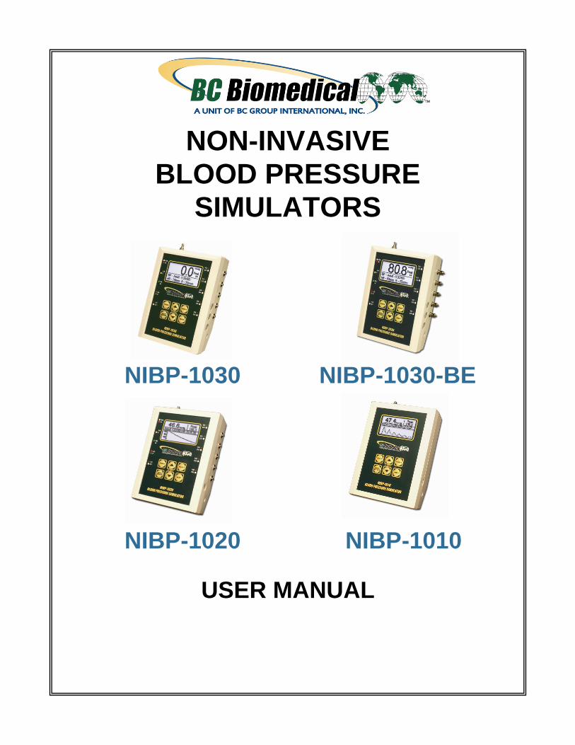
NON-INVASIVE
BLOOD PRESSURE
SIMULATORS
NIBP-1030 NIBP-1030-BE
NIBP-1020 NIBP-1010
USER MANUAL


i
WARNINGS, CAUTIONS, NOTICES ........................................................................... ii DESCRIPTION ............................................................................................................. 1 OVERVIEW .................................................................................................................. 4 KEYS ............................................................................................................................ 7 SCREENS .................................................................................................................... 8 SETUP ......................................................................................................................... 13 CONNECTIONS ........................................................................................................... 16 THEORY OF OPERATIONS ........................................................................................ 19 RUNNING A TEST ....................................................................................................... 21 MANUAL REVISIONS .................................................................................................. 33 LIMITED WARRANTY ................................................................................................. 33 SPECIFICATIONS ....................................................................................................... 34 NOTES ......................................................................................................................... 36
BC BIOMEDICAL
NIBP-1000 SERIES
TABLE OF CONTENTS
ii
WARNING - USERS
The NIBP-1000 Series is for use by skilled
technical personnel only.
WARNING - USE
The NIBP-1000 Series is intended for testing only
and should never be used in diagnostics,
treatment or any other capacity where it would
come in contact with a patient.
WARNING - CONNECTIONS All connections to patients must be removed
before connecting the DUT to the NIBP-1000
Series. A serious hazard may occur if the patient
is connected when testing with the NIBP-1000
Series. Do not connect any leads from the
patient directly to the NIBP-1000 Series or DUT.
CAUTION - ADAPTER Turn Power Off and unplug any Battery
Eliminator before cleaning the surface
of the NIBP-1000 Series.
CAUTION - MODIFICATIONS
The NIBP-1000 Series is intended for use within
the published specifications. Any application
beyond these specifications or any unauthorized
user modifications may result in hazards or
improper operation.
CAUTION - CLEANING Do not immerse. The NIBP-1000 Series should
be cleaned by wiping gently with a damp, lint-free
cloth. A mild detergent can be used if desired.
iii
CAUTION - LIQUIDS Do not submerge or spill liquids on the NIBP-
1000 Series. Do not operate the NIBP-1000
Series if internal components may have been
exposed to fluid.
CAUTION - SERVICE The NIBP-1000 Series is intended to be serviced
only by authorized service personnel.
Troubleshooting and service procedures should
only be performed by qualified technical
personnel.
CAUTION - ENVIRONMENT Exposure to environmental conditions outside
the specifications can adversely affect the
performance of the NIBP-1000 Series. Allow the
NIBP-1000 Series to acclimate to specified
conditions for at least 30 minutes before
attempting to operate it.
CAUTION - INSPECTION The NIBP-1000 Series should be inspected before
each use for wear and should be serviced if any
parts are in question.
iv
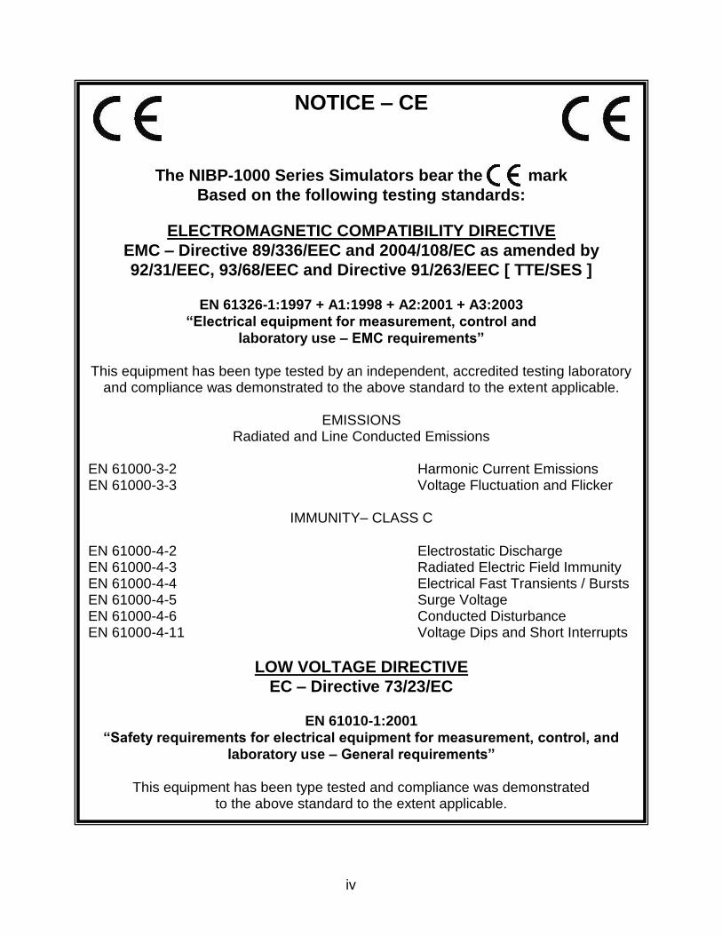
NOTICE – CE
The NIBP-1000 Series Simulators bear the mark
Based on the following testing standards:
ELECTROMAGNETIC COMPATIBILITY DIRECTIVE
EMC – Directive 89/336/EEC and 2004/108/EC as amended by
92/31/EEC, 93/68/EEC and Directive 91/263/EEC [ TTE/SES ]
EN 61326-1:1997 + A1:1998 + A2:2001 + A3:2003
“Electrical equipment for measurement, control and
laboratory use – EMC requirements”
This equipment has been type tested by an independent, accredited testing laboratory
and compliance was demonstrated to the above standard to the extent applicable.
EMISSIONS Radiated and Line Conducted Emissions
EN 61000-3-2 Harmonic Current Emissions EN 61000-3-3 Voltage Fluctuation and Flicker
IMMUNITY– CLASS C
EN 61000-4-2 Electrostatic Discharge EN 61000-4-3 Radiated Electric Field Immunity EN 61000-4-4 Electrical Fast Transients / Bursts EN 61000-4-5 Surge Voltage EN 61000-4-6 Conducted Disturbance EN 61000-4-11 Voltage Dips and Short Interrupts
LOW VOLTAGE DIRECTIVE
EC – Directive 73/23/EC
EN 61010-1:2001
“Safety requirements for electrical equipment for measurement, control, and
laboratory use – General requirements”
This equipment has been type tested and compliance was demonstrated
to the above standard to the extent applicable.
v
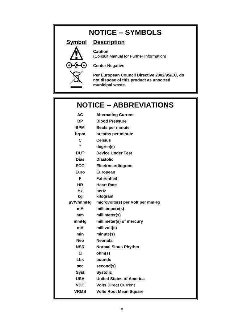
NOTICE – SYMBOLS
Symbol Description
Caution (Consult Manual for Further Information)
Center Negative
Per European Council Directive 2002/95/EC, do
not dispose of this product as unsorted
municipal waste.
NOTICE – ABBREVIATIONS
AC Alternating Current
BP Blood Pressure
BPM Beats per minute
brpm breaths per minute
C Celsius
° degree(s)
DUT Device Under Test
Dias Diastolic
ECG Electrocardiogram
Euro European
F Fahrenheit
HR Heart Rate
Hz hertz
kg kilogram
µV/V/mmHg microvolts(s) per Volt per mmHg
mA milliampere(s)
mm millimeter(s)
mmHg millimeter(s) of mercury
mV millivolt(s)
min minute(s)
Neo Neonatal
NSR Normal Sinus Rhythm
Ω ohm(s)
Lbs pounds
sec second(s)
Syst Systolic
USA United States of America
VDC Volts Direct Current
VRMS Volts Root Mean Square
vi
NIBP-1000 Series Users Manual Copyright © 2012
www.bcgroupintl.com Made in the USA
08/12 Rev 15
NOTICE – DISCLAIMER
BC GROUP INTERNATIONAL, INC. RESERVES THE RIGHT TO
MAKE CHANGES TO ITS PRODUCTS OR SPECIFICATIONS AT
ANY TIME, WITHOUT NOTICE, IN ORDER TO IMPROVE THE
DESIGN OR PERFORMANCE AND TO SUPPLY THE BEST
POSSIBLE PRODUCT. THE INFORMATION IN THIS MANUAL HAS
BEEN CAREFULLY CHECKED AND IS BELIEVED TO BE
ACCURATE. HOWEVER, NO RESPONSIBILITY IS ASSUMED FOR
INACCURACIES.
NOTICE – CONTACT INFORMATION
BC BIOMEDICAL
BC GROUP INTERNATIONAL, INC.
3081 ELM POINT INDUSTRIAL DRIVE
ST. CHARLES, MO 63301
USA
1-800-242-8428
1-314-638-3800
www.bcgroupintl.com
NOTICE – DISCLAIMER
BC GROUP INTERNATIONAL, INC. WILL NOT BE RESPONSIBLE
FOR ANY INJURIES SUSTAINED DUE TO UNAUTHORIZED
EQUIPMENT MODIFICATIONS OR APPLICATION OF EQUIPMENT
OUTSIDE OF THE PUBLISHED INTENDED USE AND
SPECIFICATIONS.
1
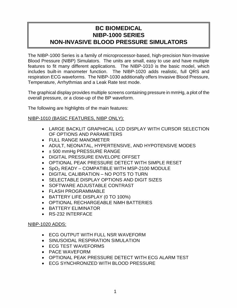
The NIBP-1000 Series is a family of microprocessor-based, high-precision Non-Invasive Blood Pressure (NIBP) Simulators. The units are small, easy to use and have multiple features to fit many different applications. The NIBP-1010 is the basic model, which includes built-in manometer function. The NIBP-1020 adds realistic, full QRS and respiration ECG waveforms. The NIBP-1030 additionally offers Invasive Blood Pressure, Temperature, Arrhythmias and a Leak Rate test mode.
The graphical display provides multiple screens containing pressure in mmHg, a plot of the overall pressure, or a close-up of the BP waveform.
The following are highlights of the main features:
NIBP-1010 (BASIC FEATURES, NIBP ONLY):
LARGE BACKLIT GRAPHICAL LCD DISPLAY WITH CURSOR SELECTION OF OPTIONS AND PARAMETERS
FULL RANGE MANOMETER
ADULT, NEONATAL, HYPERTENSIVE, AND HYPOTENSIVE MODES
± 500 mmHg PRESSURE RANGE
DIGITAL PRESSURE ENVELOPE OFFSET
OPTIONAL PEAK PRESSURE DETECT WITH SIMPLE RESET
SpO2 READY – COMPATIBLE WITH MSP-2100 MODULE
DIGITAL CALIBRATION – NO POTS TO TURN
SELECTABLE DISPLAY OPTIONS AND DIGIT SIZES
SOFTWARE ADJUSTABLE CONTRAST
FLASH PROGRAMMABLE
BATTERY LIFE DISPLAY (0 TO 100%)
OPTIONAL RECHARGEABLE NiMH BATTERIES
BATTERY ELIMINATOR
RS-232 INTERFACE
NIBP-1020 ADDS:
ECG OUTPUT WITH FULL NSR WAVEFORM
SINUSOIDAL RESPIRATION SIMULATION
ECG TEST WAVEFORMS
PACE WAVEFORM
OPTIONAL PEAK PRESSURE DETECT WITH ECG ALARM TEST
ECG SYNCHRONIZED WITH BLOOD PRESSURE
BC BIOMEDICAL
NIBP-1000 SERIES
NON-INVASIVE BLOOD PRESSURE SIMULATORS
2
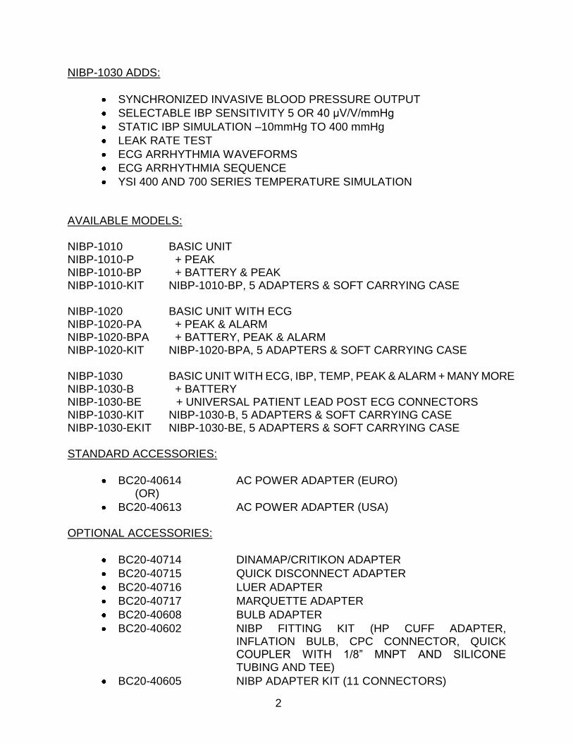
NIBP-1030 ADDS:
SYNCHRONIZED INVASIVE BLOOD PRESSURE OUTPUT
SELECTABLE IBP SENSITIVITY 5 OR 40 μV/V/mmHg
STATIC IBP SIMULATION –10mmHg TO 400 mmHg
LEAK RATE TEST
ECG ARRHYTHMIA WAVEFORMS
ECG ARRHYTHMIA SEQUENCE
YSI 400 AND 700 SERIES TEMPERATURE SIMULATION AVAILABLE MODELS: NIBP-1010 BASIC UNIT NIBP-1010-P + PEAK NIBP-1010-BP + BATTERY & PEAK NIBP-1010-KIT NIBP-1010-BP, 5 ADAPTERS & SOFT CARRYING CASE NIBP-1020 BASIC UNIT WITH ECG NIBP-1020-PA + PEAK & ALARM NIBP-1020-BPA + BATTERY, PEAK & ALARM NIBP-1020-KIT NIBP-1020-BPA, 5 ADAPTERS & SOFT CARRYING CASE NIBP-1030 BASIC UNIT WITH ECG, IBP, TEMP, PEAK & ALARM + MANY MORE NIBP-1030-B + BATTERY NIBP-1030-BE + UNIVERSAL PATIENT LEAD POST ECG CONNECTORS NIBP-1030-KIT NIBP-1030-B, 5 ADAPTERS & SOFT CARRYING CASE NIBP-1030-EKIT NIBP-1030-BE, 5 ADAPTERS & SOFT CARRYING CASE STANDARD ACCESSORIES:
BC20-40614 AC POWER ADAPTER (EURO) (OR)
BC20-40613 AC POWER ADAPTER (USA) OPTIONAL ACCESSORIES:
BC20-40714 DINAMAP/CRITIKON ADAPTER
BC20-40715 QUICK DISCONNECT ADAPTER
BC20-40716 LUER ADAPTER
BC20-40717 MARQUETTE ADAPTER
BC20-40608 BULB ADAPTER
BC20-40602 NIBP FITTING KIT (HP CUFF ADAPTER, INFLATION BULB, CPC CONNECTOR, QUICK COUPLER WITH 1/8” MNPT AND SILICONE TUBING AND TEE)
BC20-40605 NIBP ADAPTER KIT (11 CONNECTORS)
3
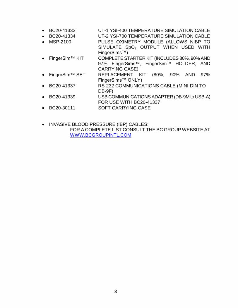
BC20-41333 UT-1 YSI-400 TEMPERATURE SIMULATION CABLE
BC20-41334 UT-2 YSI-700 TEMPERATURE SIMULATION CABLE
MSP-2100 PULSE OXIMETRY MODULE (ALLOWS NIBP TO SIMULATE SpO2 OUTPUT WHEN USED WITH FingerSims™)
FingerSim™ KIT COMPLETE STARTER KIT (INCLUDES 80%, 90% AND 97% FingerSims™, FingerSim™ HOLDER, AND CARRYING CASE)
FingerSim™ SET REPLACEMENT KIT (80%, 90% AND 97% FingerSims™ ONLY)
BC20-41337 RS-232 COMMUNICATIONS CABLE (MINI-DIN TO DB-9F)
BC20-41339 USB COMMUNICATIONS ADAPTER (DB-9M to USB-A) FOR USE WITH BC20-41337
BC20-30111 SOFT CARRYING CASE
INVASIVE BLOOD PRESSURE (IBP) CABLES: FOR A COMPLETE LIST CONSULT THE BC GROUP WEBSITE AT WWW.BCGROUPINTL.COM
4
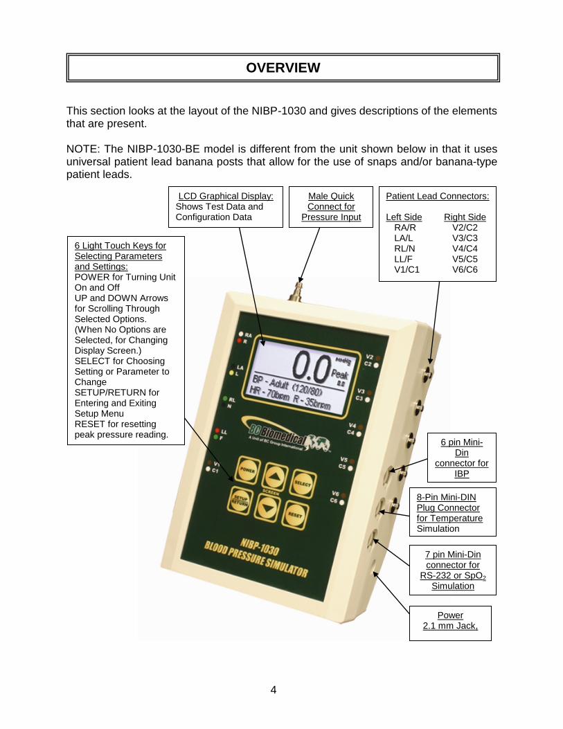
This section looks at the layout of the NIBP-1030 and gives descriptions of the elements that are present. NOTE: The NIBP-1030-BE model is different from the unit shown below in that it uses universal patient lead banana posts that allow for the use of snaps and/or banana-type patient leads.
OVERVIEW
Patient Lead Connectors: Left Side Right Side RA/R V2/C2 LA/L V3/C3 RL/N V4/C4 LL/F V5/C5 V1/C1 V6/C6
6 Light Touch Keys for Selecting Parameters and Settings: POWER for Turning Unit On and Off UP and DOWN Arrows for Scrolling Through Selected Options. (When No Options are Selected, for Changing Display Screen.) SELECT for Choosing Setting or Parameter to Change SETUP/RETURN for Entering and Exiting Setup Menu RESET for resetting peak pressure reading.
LCD Graphical Display: Shows Test Data and Configuration Data
Male Quick Connect for
Pressure Input
Power 2.1 mm Jack,
7 pin Mini-Din connector for
RS-232 or SpO2 Simulation
8-Pin Mini-DIN Plug Connector for Temperature Simulation
6 pin Mini-Din
connector for IBP
Simulation
5
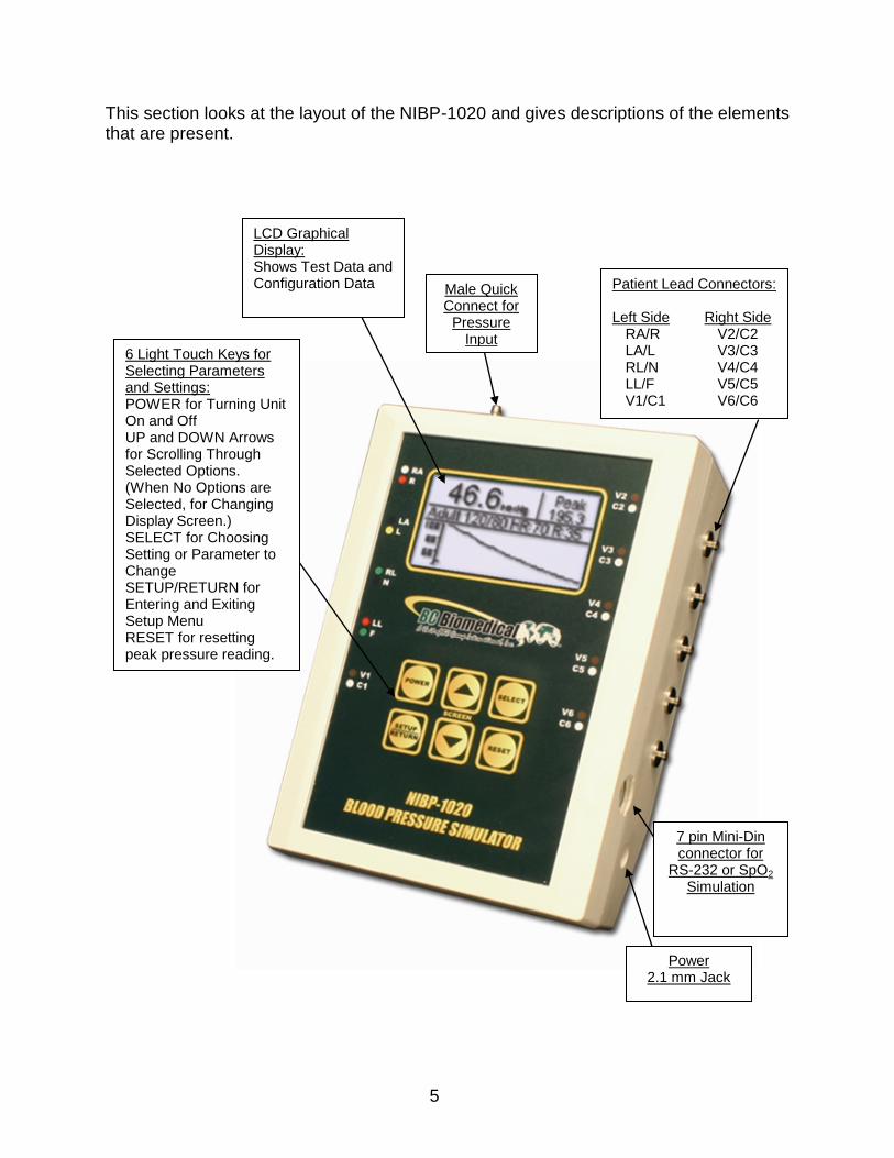
This section looks at the layout of the NIBP-1020 and gives descriptions of the elements that are present.
Patient Lead Connectors: Left Side Right Side RA/R V2/C2 LA/L V3/C3 RL/N V4/C4 LL/F V5/C5 V1/C1 V6/C6
LCD Graphical Display: Shows Test Data and Configuration Data Male Quick
Connect for Pressure
Input
7 pin Mini-Din connector for
RS-232 or SpO2 Simulation
Power 2.1 mm Jack
6 Light Touch Keys for Selecting Parameters and Settings: POWER for Turning Unit On and Off UP and DOWN Arrows for Scrolling Through Selected Options. (When No Options are Selected, for Changing Display Screen.) SELECT for Choosing Setting or Parameter to Change SETUP/RETURN for Entering and Exiting Setup Menu RESET for resetting peak pressure reading.
6
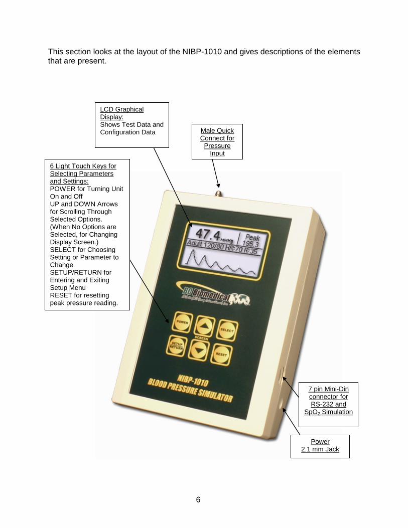
This section looks at the layout of the NIBP-1010 and gives descriptions of the elements that are present.
Male Quick Connect for
Pressure Input
Power 2.1 mm Jack
7 pin Mini-Din connector for RS-232 and
SpO2 Simulation
6 Light Touch Keys for Selecting Parameters and Settings: POWER for Turning Unit On and Off UP and DOWN Arrows for Scrolling Through Selected Options. (When No Options are Selected, for Changing Display Screen.) SELECT for Choosing Setting or Parameter to Change SETUP/RETURN for Entering and Exiting Setup Menu RESET for resetting peak pressure reading.
LCD Graphical Display: Shows Test Data and Configuration Data
7
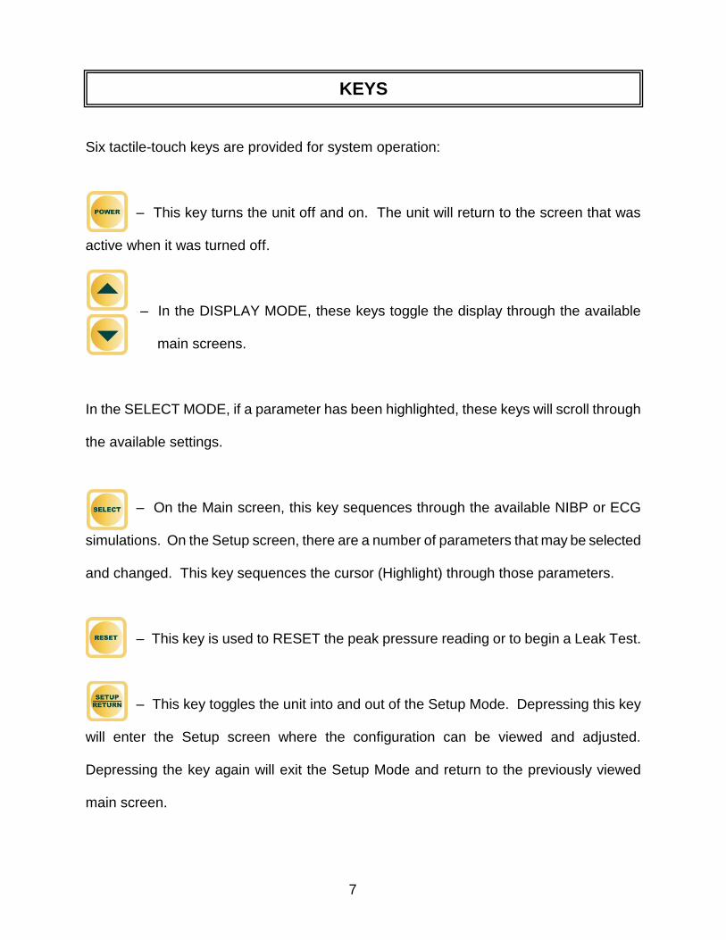
Six tactile-touch keys are provided for system operation:
– This key turns the unit off and on. The unit will return to the screen that was
active when it was turned off.
– In the DISPLAY MODE, these keys toggle the display through the available
main screens.
In the SELECT MODE, if a parameter has been highlighted, these keys will scroll through
the available settings.
– On the Main screen, this key sequences through the available NIBP or ECG
simulations. On the Setup screen, there are a number of parameters that may be selected
and changed. This key sequences the cursor (Highlight) through those parameters.
– This key is used to RESET the peak pressure reading or to begin a Leak Test.
– This key toggles the unit into and out of the Setup Mode. Depressing this key
will enter the Setup screen where the configuration can be viewed and adjusted.
Depressing the key again will exit the Setup Mode and return to the previously viewed
main screen.
KEYS
8
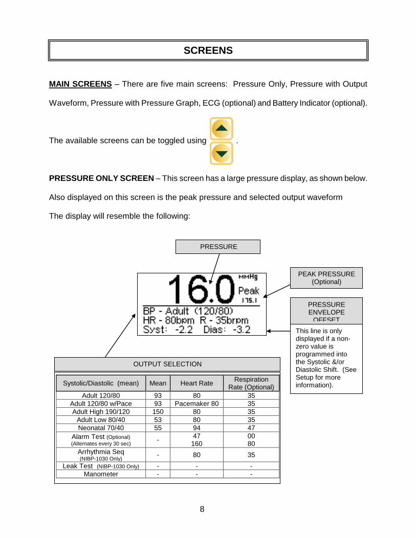
MAIN SCREENS – There are five main screens: Pressure Only, Pressure with Output
Waveform, Pressure with Pressure Graph, ECG (optional) and Battery Indicator (optional).
The available screens can be toggled using .
PRESSURE ONLY SCREEN – This screen has a large pressure display, as shown below.
Also displayed on this screen is the peak pressure and selected output waveform
The display will resemble the following:
SCREENS
Systolic/Diastolic (mean) Mean Heart Rate Respiration
Rate (Optional)
Adult 120/80 93 80 35
Adult 120/80 w/Pace 93 Pacemaker 80 35
Adult High 190/120 150 80 35
Adult Low 80/40 53 80 35
Neonatal 70/40 55 94 47
Alarm Test (Optional) (Alternates every 30 sec)
- 47 160
00 80
Arrhythmia Seq (NIBP-1030 Only)
- 80 35
Leak Test (NIBP-1030 Only) - - -
Manometer - - -
OUTPUT SELECTION
PRESSURE ENVELOPE
OFFSET
This line is only displayed if a non-zero value is programmed into the Systolic &/or Diastolic Shift. (See Setup for more information).
PRESSURE
PEAK PRESSURE (Optional)
9
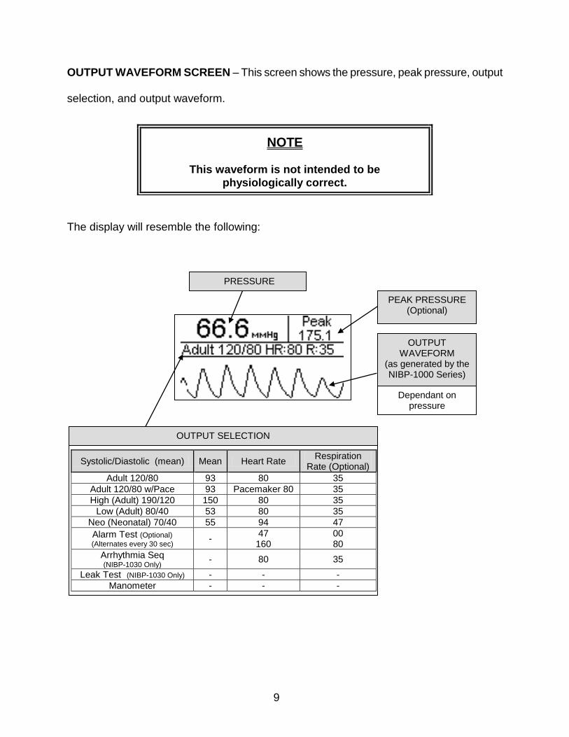
OUTPUT WAVEFORM SCREEN – This screen shows the pressure, peak pressure, output
selection, and output waveform.
The display will resemble the following:
NOTE
This waveform is not intended to be
physiologically correct.
OUTPUT WAVEFORM
(as generated by the NIBP-1000 Series)
Dependant on pressure
PEAK PRESSURE (Optional)
Systolic/Diastolic (mean) Mean Heart Rate Respiration
Rate (Optional)
Adult 120/80 93 80 35
Adult 120/80 w/Pace 93 Pacemaker 80 35
High (Adult) 190/120 150 80 35
Low (Adult) 80/40 53 80 35
Neo (Neonatal) 70/40 55 94 47
Alarm Test (Optional) (Alternates every 30 sec)
- 47 160
00 80
Arrhythmia Seq (NIBP-1030 Only)
- 80 35
Leak Test (NIBP-1030 Only) - - -
Manometer - - -
OUTPUT SELECTION
PRESSURE
10
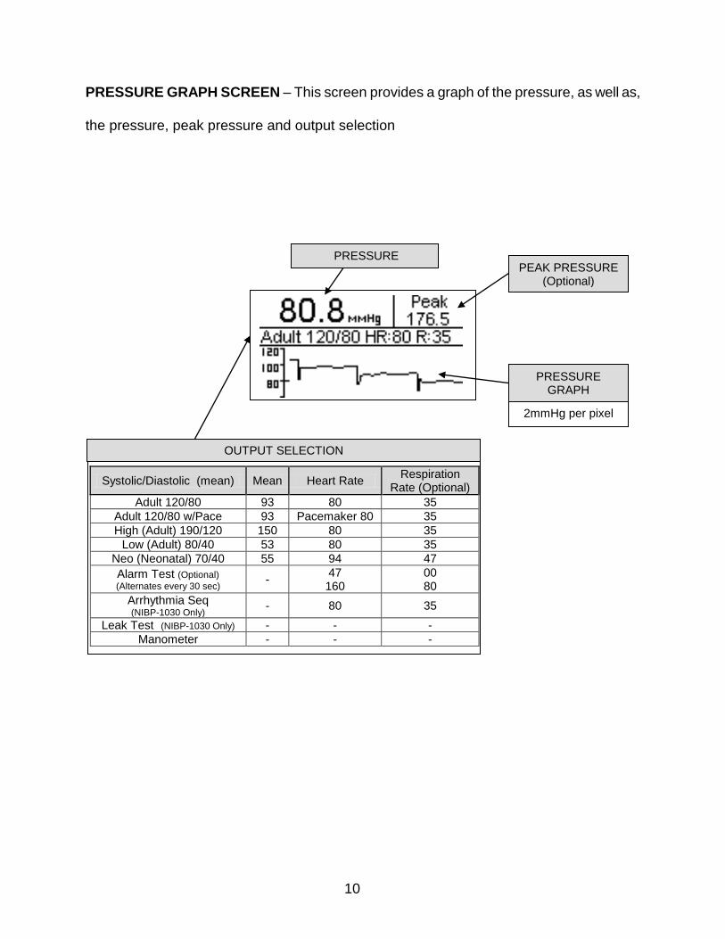
PRESSURE GRAPH SCREEN – This screen provides a graph of the pressure, as well as,
the pressure, peak pressure and output selection
2mmHg per pixel
PEAK PRESSURE (Optional)
PRESSURE
Systolic/Diastolic (mean) Mean Heart Rate Respiration
Rate (Optional)
Adult 120/80 93 80 35
Adult 120/80 w/Pace 93 Pacemaker 80 35
High (Adult) 190/120 150 80 35
Low (Adult) 80/40 53 80 35
Neo (Neonatal) 70/40 55 94 47
Alarm Test (Optional) (Alternates every 30 sec)
- 47 160
00 80
Arrhythmia Seq (NIBP-1030 Only)
- 80 35
Leak Test (NIBP-1030 Only) - - -
Manometer - - -
OUTPUT SELECTION
PRESSURE GRAPH
11
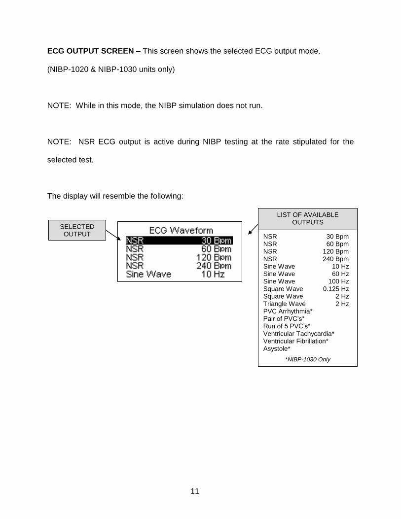
ECG OUTPUT SCREEN – This screen shows the selected ECG output mode.
(NIBP-1020 & NIBP-1030 units only)
NOTE: While in this mode, the NIBP simulation does not run.
NOTE: NSR ECG output is active during NIBP testing at the rate stipulated for the
selected test.
The display will resemble the following:
LIST OF AVAILABLE OUTPUTS
SELECTED OUTPUT NSR 30 Bpm
NSR 60 Bpm NSR 120 Bpm NSR 240 Bpm Sine Wave 10 Hz Sine Wave 60 Hz Sine Wave 100 Hz Square Wave 0.125 Hz Square Wave 2 Hz Triangle Wave 2 Hz PVC Arrhythmia* Pair of PVC’s* Run of 5 PVC’s* Ventricular Tachycardia* Ventricular Fibrillation* Asystole*
*NIBP-1030 Only
12
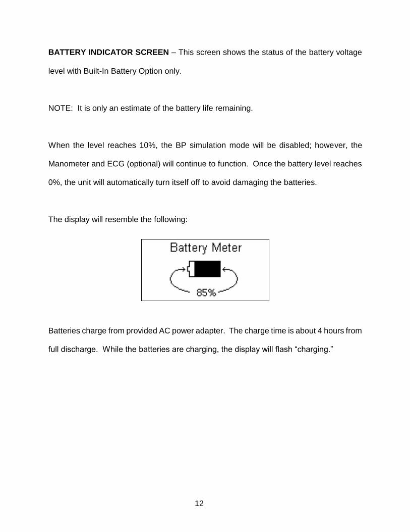
BATTERY INDICATOR SCREEN – This screen shows the status of the battery voltage
level with Built-In Battery Option only.
NOTE: It is only an estimate of the battery life remaining.
When the level reaches 10%, the BP simulation mode will be disabled; however, the
Manometer and ECG (optional) will continue to function. Once the battery level reaches
0%, the unit will automatically turn itself off to avoid damaging the batteries.
The display will resemble the following:
Batteries charge from provided AC power adapter. The charge time is about 4 hours from
full discharge. While the batteries are charging, the display will flash “charging.”
13
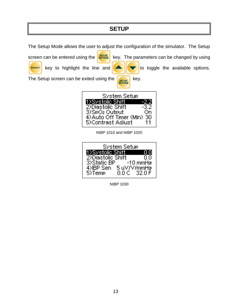
The Setup Mode allows the user to adjust the configuration of the simulator. The Setup
screen can be entered using the key. The parameters can be changed by using
key to highlight the line and to toggle the available options.
The Setup screen can be exited using the key.
NIBP 1010 and NIBP 1020
NIBP 1030
SETUP
14
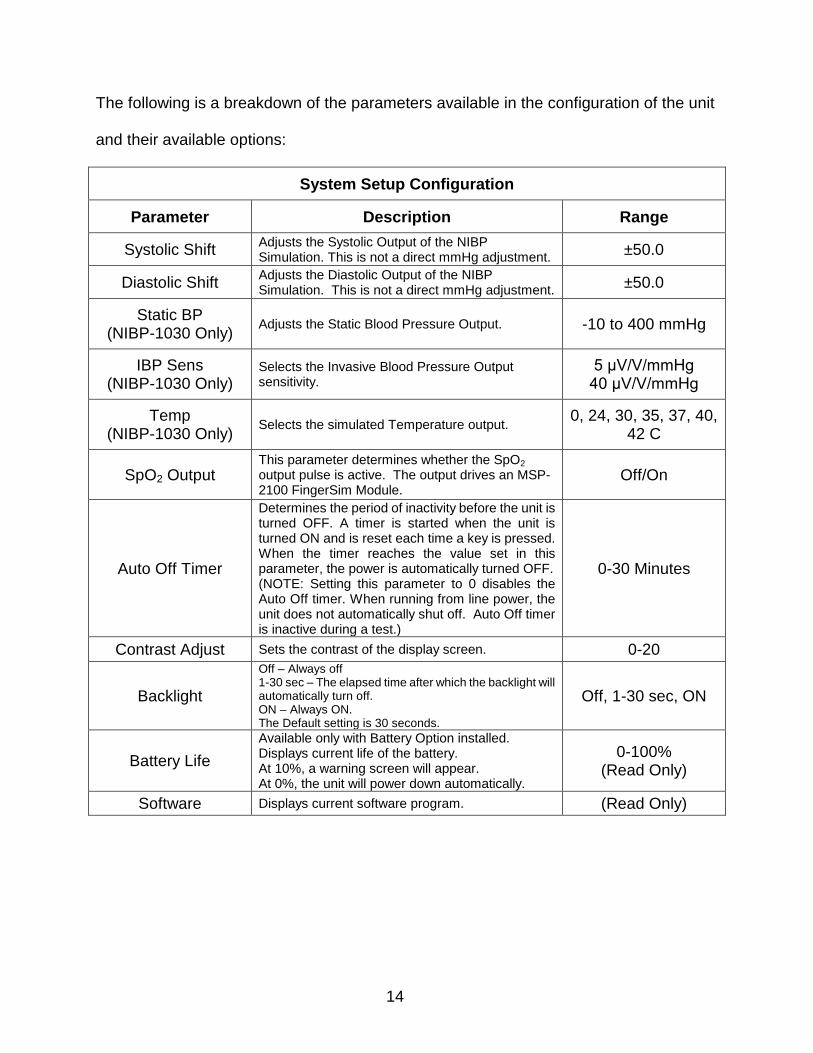
The following is a breakdown of the parameters available in the configuration of the unit
and their available options:
System Setup Configuration
Parameter Description Range
Systolic Shift Adjusts the Systolic Output of the NIBP Simulation. This is not a direct mmHg adjustment.
±50.0
Diastolic Shift Adjusts the Diastolic Output of the NIBP Simulation. This is not a direct mmHg adjustment.
±50.0
Static BP (NIBP-1030 Only)
Adjusts the Static Blood Pressure Output. -10 to 400 mmHg
IBP Sens (NIBP-1030 Only)
Selects the Invasive Blood Pressure Output sensitivity.
5 μV/V/mmHg 40 μV/V/mmHg
Temp (NIBP-1030 Only)
Selects the simulated Temperature output. 0, 24, 30, 35, 37, 40,
42 C
SpO2 Output This parameter determines whether the SpO2 output pulse is active. The output drives an MSP-2100 FingerSim Module.
Off/On
Auto Off Timer
Determines the period of inactivity before the unit is turned OFF. A timer is started when the unit is turned ON and is reset each time a key is pressed. When the timer reaches the value set in this parameter, the power is automatically turned OFF. (NOTE: Setting this parameter to 0 disables the Auto Off timer. When running from line power, the unit does not automatically shut off. Auto Off timer is inactive during a test.)
0-30 Minutes
Contrast Adjust Sets the contrast of the display screen. 0-20
Backlight
Off – Always off 1-30 sec – The elapsed time after which the backlight will automatically turn off. ON – Always ON. The Default setting is 30 seconds.
Off, 1-30 sec, ON
Battery Life
Available only with Battery Option installed. Displays current life of the battery. At 10%, a warning screen will appear. At 0%, the unit will power down automatically.
0-100% (Read Only)
Software Displays current software program. (Read Only)
15
SYSTOLIC AND DIASTOLIC SHIFT – The NIBP-1000 Series is equipped with the option
to shift test results to compensate for different methods of measuring Oscillometric NIBP
by various manufacturers and models of devices under test.
There are no absolute standards for Oscillometric NIBP readings; therefore, for a number
of reasons (including patents, technology, etc.), each manufacturer has established a
different method for evaluating the oscillometric pulses. Due to these varying methods,
precisely the same waveforms will give different results on different manufacturer’s units.
The normal technique used is to run the monitor against a fixed source like the NIBP-1000,
with the understanding that each manufacturer has a predictable error from this norm.
While this is generally the most direct method, users have asked for a method to correct
for this difference, making the monitors read the same as the test unit. The Systolic and
Diastolic Shift settings allow for just such correction.
These adjustments are indicated in a line added to the main display to inform the user of
any shift that has been programmed into the system. This is done so there is no
misunderstanding of the meaning of the results.
CAUTION
These adjustments must be used with caution as they will
allow the user to adjust the output results to invalid values.
These adjustments should only be used to aid in the
simplification of testing and with documented controls.
16
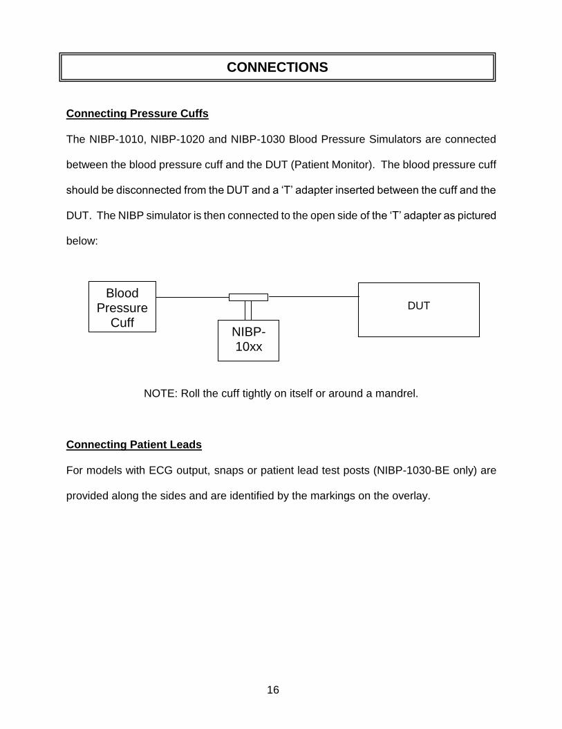
Connecting Pressure Cuffs
The NIBP-1010, NIBP-1020 and NIBP-1030 Blood Pressure Simulators are connected
between the blood pressure cuff and the DUT (Patient Monitor). The blood pressure cuff
should be disconnected from the DUT and a ‘T’ adapter inserted between the cuff and the
DUT. The NIBP simulator is then connected to the open side of the ‘T’ adapter as pictured
below:
NOTE: Roll the cuff tightly on itself or around a mandrel.
Connecting Patient Leads
For models with ECG output, snaps or patient lead test posts (NIBP-1030-BE only) are
provided along the sides and are identified by the markings on the overlay.
Blood Pressure
Cuff
DUT
NIBP-10xx
CONNECTIONS
17
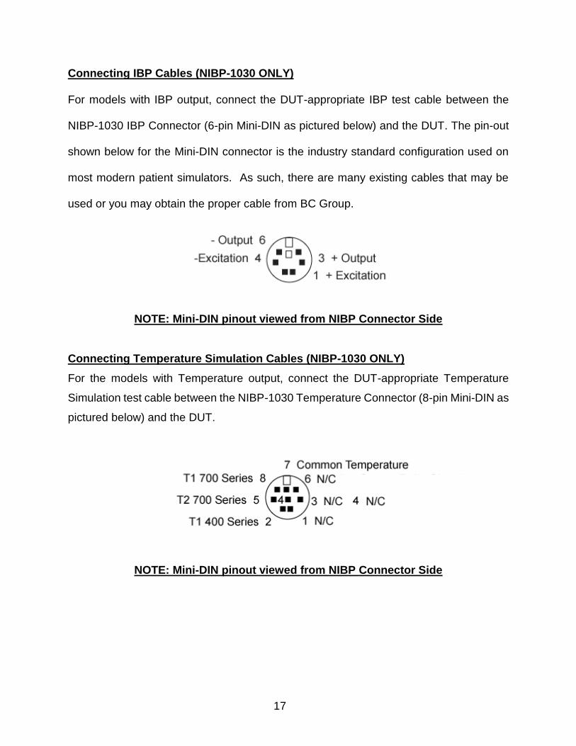
Connecting IBP Cables (NIBP-1030 ONLY)
For models with IBP output, connect the DUT-appropriate IBP test cable between the
NIBP-1030 IBP Connector (6-pin Mini-DIN as pictured below) and the DUT. The pin-out
shown below for the Mini-DIN connector is the industry standard configuration used on
most modern patient simulators. As such, there are many existing cables that may be
used or you may obtain the proper cable from BC Group.
NOTE: Mini-DIN pinout viewed from NIBP Connector Side
Connecting Temperature Simulation Cables (NIBP-1030 ONLY)
For the models with Temperature output, connect the DUT-appropriate Temperature
Simulation test cable between the NIBP-1030 Temperature Connector (8-pin Mini-DIN as
pictured below) and the DUT.
NOTE: Mini-DIN pinout viewed from NIBP Connector Side
18
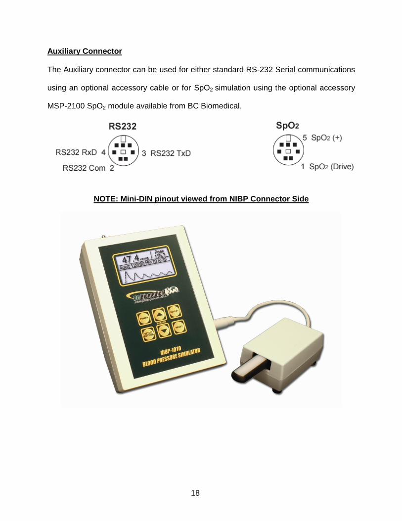
Auxiliary Connector
The Auxiliary connector can be used for either standard RS-232 Serial communications
using an optional accessory cable or for SpO2 simulation using the optional accessory
MSP-2100 SpO2 module available from BC Biomedical.
NOTE: Mini-DIN pinout viewed from NIBP Connector Side
19
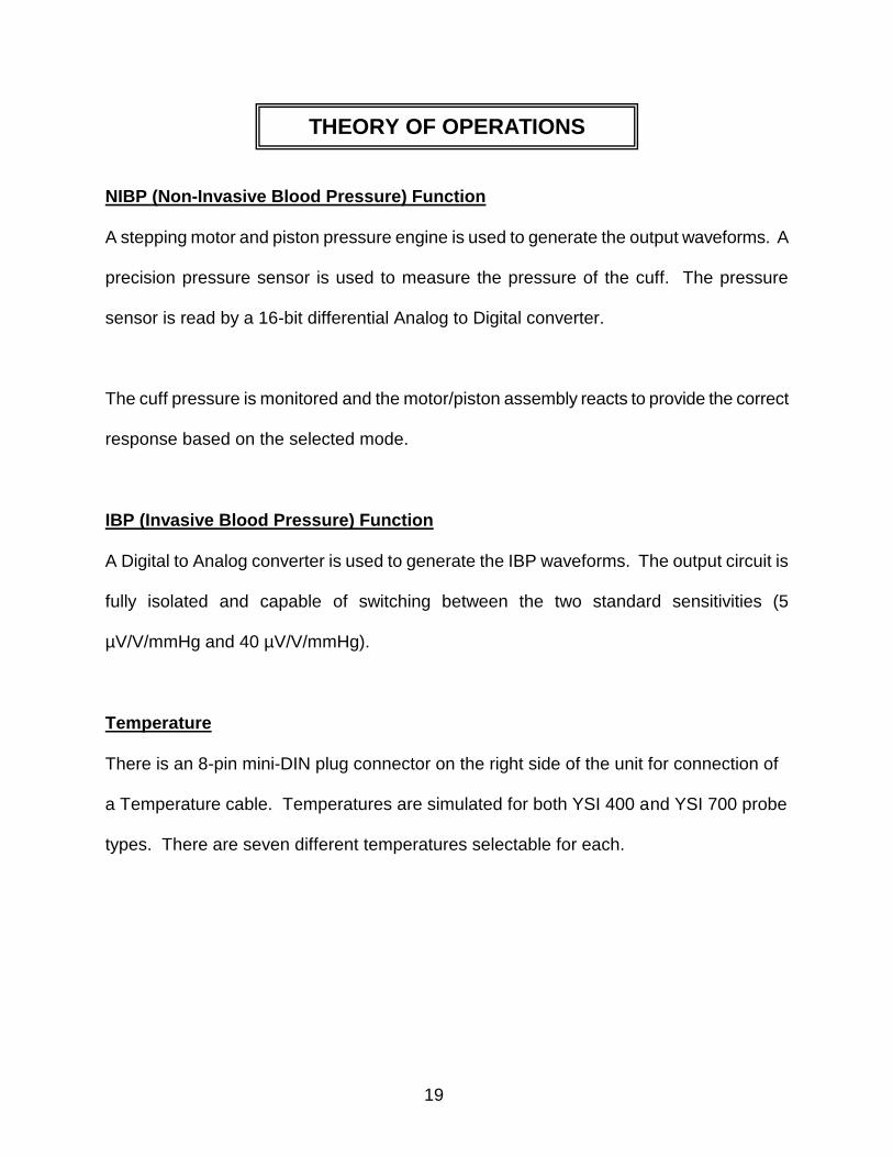
NIBP (Non-Invasive Blood Pressure) Function
A stepping motor and piston pressure engine is used to generate the output waveforms. A
precision pressure sensor is used to measure the pressure of the cuff. The pressure
sensor is read by a 16-bit differential Analog to Digital converter.
The cuff pressure is monitored and the motor/piston assembly reacts to provide the correct
response based on the selected mode.
IBP (Invasive Blood Pressure) Function
A Digital to Analog converter is used to generate the IBP waveforms. The output circuit is
fully isolated and capable of switching between the two standard sensitivities (5
µV/V/mmHg and 40 µV/V/mmHg).
Temperature
There is an 8-pin mini-DIN plug connector on the right side of the unit for connection of
a Temperature cable. Temperatures are simulated for both YSI 400 and YSI 700 probe
types. There are seven different temperatures selectable for each.
THEORY OF OPERATIONS

20
ECG Function
A Digital to Analog converter is used to generate the ECG outputs based on stored
waveform data for standard ECG and Arrhythmias.
Respiration Function
A Digital to Analog converter is used to generate the respiration waveform. The respiration
output is present on the LA ECG lead only. Refer to Monitor manual to determine which
lead the Monitor uses for respiration. It may be necessary to reverse the LA and LL leads
for respiration to be detected.
21
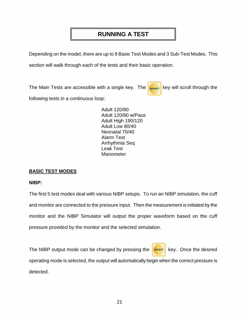
Depending on the model, there are up to 9 Basic Test Modes and 3 Sub-Test Modes. This
section will walk through each of the tests and their basic operation.
The Main Tests are accessible with a single key. The key will scroll through the
following tests in a continuous loop:
Adult 120/80 Adult 120/80 w/Pace Adult High 190/120 Adult Low 80/40 Neonatal 70/40 Alarm Test Arrhythmia Seq Leak Test Manometer
BASIC TEST MODES
NIBP:
The first 5 test modes deal with various NIBP setups. To run an NIBP simulation, the cuff
and monitor are connected to the pressure input. Then the measurement is initiated by the
monitor and the NIBP Simulator will output the proper waveform based on the cuff
pressure provided by the monitor and the selected simulation.
The NIBP output mode can be changed by pressing the key. Once the desired
operating mode is selected, the output will automatically begin when the correct pressure is
detected.
RUNNING A TEST
22
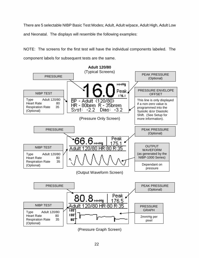
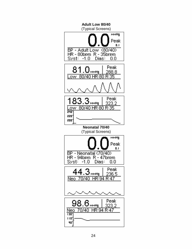
There are 5 selectable NIBP Basic Test Modes; Adult, Adult w/pace, Adult High, Adult Low
and Neonatal. The displays will resemble the following examples:
NOTE: The screens for the first test will have the individual components labeled. The
component labels for subsequent tests are the same.
Adult 120/80 (Typical Screens)
(Pressure Only Screen)
(Output Waveform Screen)
(Pressure Graph Screen)
PEAK PRESSURE (Optional)
PRESSURE
PRESSURE ENVELOPE OFFSET
This line is only displayed if a non-zero value is programmed into the Systolic &/or Diastolic Shift. (See Setup for more information).
PEAK PRESSURE (Optional)
NIBP TEST
PEAK PRESSURE (Optional)
PRESSURE
Type Adult 120/80 Heart Rate 80 Respiration Rate 35 (Optional)
NIBP TEST
PRESSURE
OUTPUT WAVEFORM
(as generated by the NIBP-1000 Series)
Dependant on pressure
PRESSURE GRAPH
2mmHg per pixel
Type Adult 120/80 Heart Rate 80 Respiration Rate 35 (Optional)
Type Adult 120/80 Heart Rate 80 Respiration Rate 35 (Optional)
NIBP TEST
23
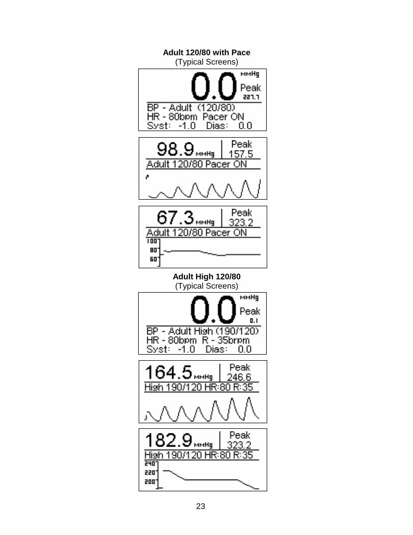
Adult 120/80 with Pace (Typical Screens)
Adult High 120/80 (Typical Screens)
24
Adult Low 80/40 (Typical Screens)
Neonatal 70/40 (Typical Screens)
25
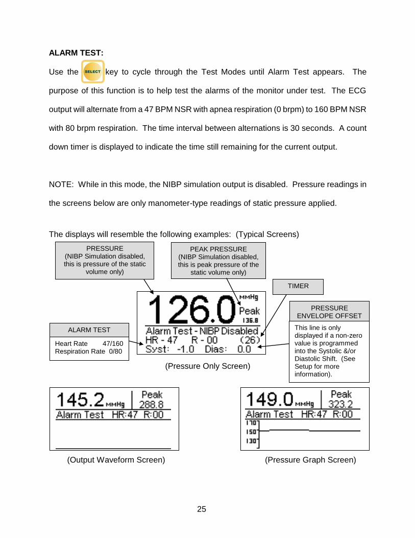
ALARM TEST:
Use the key to cycle through the Test Modes until Alarm Test appears. The
purpose of this function is to help test the alarms of the monitor under test. The ECG
output will alternate from a 47 BPM NSR with apnea respiration (0 brpm) to 160 BPM NSR
with 80 brpm respiration. The time interval between alternations is 30 seconds. A count
down timer is displayed to indicate the time still remaining for the current output.
NOTE: While in this mode, the NIBP simulation output is disabled. Pressure readings in
the screens below are only manometer-type readings of static pressure applied.
The displays will resemble the following examples: (Typical Screens)
(Pressure Only Screen)
(Output Waveform Screen) (Pressure Graph Screen)
PEAK PRESSURE (NIBP Simulation disabled, this is peak pressure of the
static volume only)
ALARM TEST
PRESSURE (NIBP Simulation disabled, this is pressure of the static
volume only)
PRESSURE ENVELOPE OFFSET
This line is only displayed if a non-zero value is programmed into the Systolic &/or Diastolic Shift. (See Setup for more information).
Heart Rate 47/160 Respiration Rate 0/80
TIMER
26
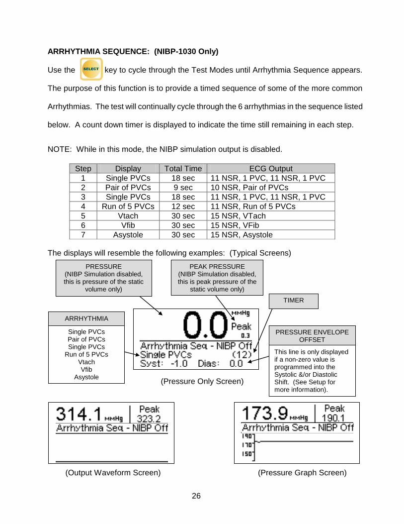
ARRHYTHMIA SEQUENCE: (NIBP-1030 Only)
Use the key to cycle through the Test Modes until Arrhythmia Sequence appears.
The purpose of this function is to provide a timed sequence of some of the more common
Arrhythmias. The test will continually cycle through the 6 arrhythmias in the sequence listed
below. A count down timer is displayed to indicate the time still remaining in each step.
NOTE: While in this mode, the NIBP simulation output is disabled.
The displays will resemble the following examples: (Typical Screens)
(Pressure Only Screen)
(Output Waveform Screen) (Pressure Graph Screen)
Step Display Total Time ECG Output
1 Single PVCs 18 sec 11 NSR, 1 PVC, 11 NSR, 1 PVC
2 Pair of PVCs 9 sec 10 NSR, Pair of PVCs
3 Single PVCs 18 sec 11 NSR, 1 PVC, 11 NSR, 1 PVC
4 Run of 5 PVCs 12 sec 11 NSR, Run of 5 PVCs
5 Vtach 30 sec 15 NSR, VTach
6 Vfib 30 sec 15 NSR, VFib
7 Asystole 30 sec 15 NSR, Asystole
Single PVCs Pair of PVCs Single PVCs
Run of 5 PVCs Vtach Vfib
Asystole
ARRHYTHMIA
PRESSURE ENVELOPE OFFSET
This line is only displayed if a non-zero value is programmed into the Systolic &/or Diastolic Shift. (See Setup for more information).
PRESSURE (NIBP Simulation disabled, this is pressure of the static
volume only)
PEAK PRESSURE (NIBP Simulation disabled, this is peak pressure of the
static volume only)
TIMER
27
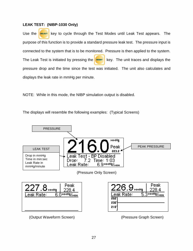
LEAK TEST: (NIBP-1030 Only)
Use the key to cycle through the Test Modes until Leak Test appears. The
purpose of this function is to provide a standard pressure leak test. The pressure input is
connected to the system that is to be monitored. Pressure is then applied to the system.
The Leak Test is initiated by pressing the key. The unit traces and displays the
pressure drop and the time since the test was initiated. The unit also calculates and
displays the leak rate in mmHg per minute.
NOTE: While in this mode, the NIBP simulation output is disabled.
The displays will resemble the following examples: (Typical Screens)
(Pressure Only Screen)
(Output Waveform Screen) (Pressure Graph Screen)
LEAK TEST
PRESSURE
PEAK PRESSURE
Drop in mmHg Time in min:sec Leak Rate in mmHg/minute
28
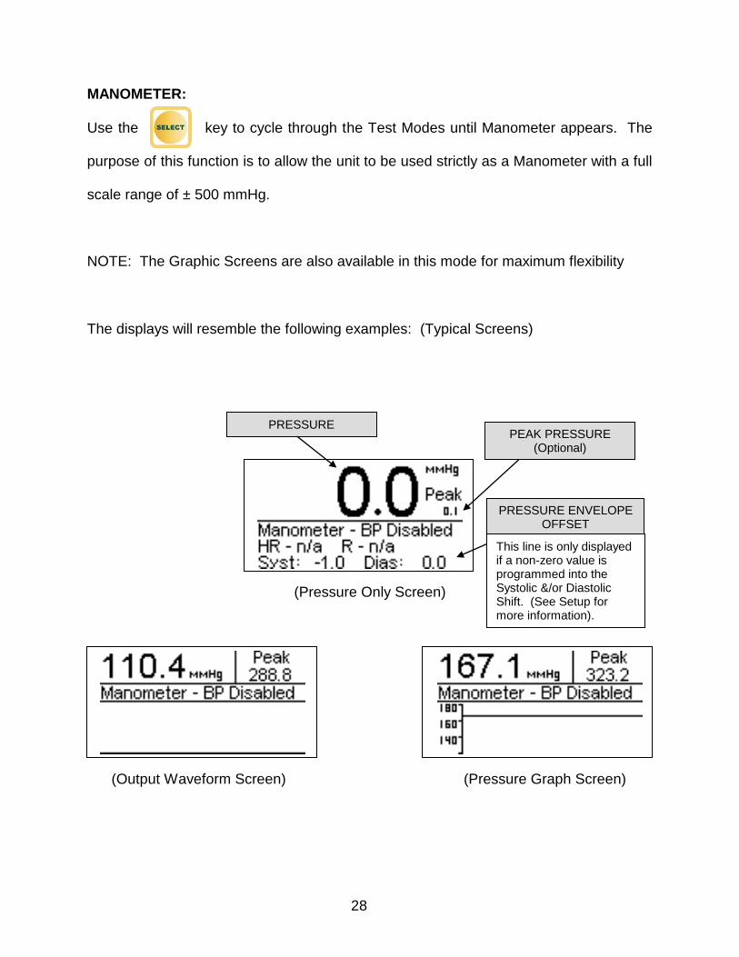
MANOMETER:
Use the key to cycle through the Test Modes until Manometer appears. The
purpose of this function is to allow the unit to be used strictly as a Manometer with a full
scale range of ± 500 mmHg.
NOTE: The Graphic Screens are also available in this mode for maximum flexibility
The displays will resemble the following examples: (Typical Screens)
(Pressure Only Screen)
(Output Waveform Screen) (Pressure Graph Screen)
PRESSURE
This line is only displayed if a non-zero value is programmed into the Systolic &/or Diastolic Shift. (See Setup for more information).
PRESSURE ENVELOPE OFFSET
PEAK PRESSURE (Optional)
29
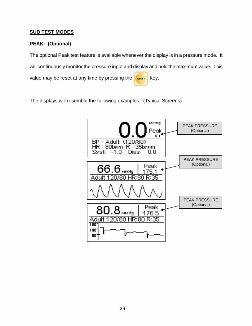
SUB TEST MODES
PEAK: (Optional)
The optional Peak test feature is available whenever the display is in a pressure mode. It
will continuously monitor the pressure input and display and hold the maximum value. This
value may be reset at any time by pressing the key.
The displays will resemble the following examples: (Typical Screens)
PEAK PRESSURE (Optional)
PEAK PRESSURE (Optional)
PEAK PRESSURE (Optional)
30
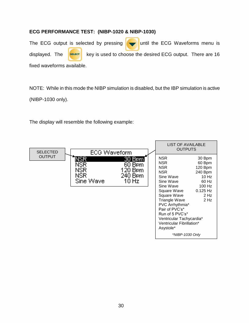
ECG PERFORMANCE TEST: (NIBP-1020 & NIBP-1030)
The ECG output is selected by pressing until the ECG Waveforms menu is
displayed. The key is used to choose the desired ECG output. There are 16
fixed waveforms available.
NOTE: While in this mode the NIBP simulation is disabled, but the IBP simulation is active
(NIBP-1030 only).
The display will resemble the following example:
LIST OF AVAILABLE OUTPUTS
NSR 30 Bpm NSR 60 Bpm NSR 120 Bpm NSR 240 Bpm Sine Wave 10 Hz Sine Wave 60 Hz Sine Wave 100 Hz Square Wave 0.125 Hz Square Wave 2 Hz Triangle Wave 2 Hz PVC Arrhythmia* Pair of PVC’s* Run of 5 PVC’s* Ventricular Tachycardia* Ventricular Fibrillation* Asystole*
*NIBP-1030 Only
SELECTED OUTPUT
31
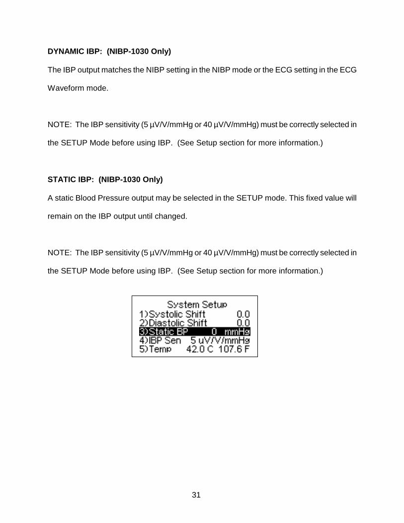
DYNAMIC IBP: (NIBP-1030 Only)
The IBP output matches the NIBP setting in the NIBP mode or the ECG setting in the ECG
Waveform mode.
NOTE: The IBP sensitivity (5 µV/V/mmHg or 40 µV/V/mmHg) must be correctly selected in
the SETUP Mode before using IBP. (See Setup section for more information.)
STATIC IBP: (NIBP-1030 Only)
A static Blood Pressure output may be selected in the SETUP mode. This fixed value will
remain on the IBP output until changed.
NOTE: The IBP sensitivity (5 µV/V/mmHg or 40 µV/V/mmHg) must be correctly selected in
the SETUP Mode before using IBP. (See Setup section for more information.)
32
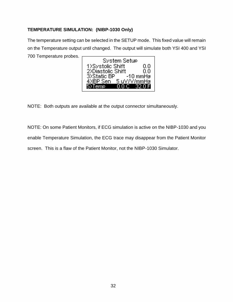
TEMPERATURE SIMULATION: (NIBP-1030 Only)
The temperature setting can be selected in the SETUP mode. This fixed value will remain
on the Temperature output until changed. The output will simulate both YSI 400 and YSI
700 Temperature probes.
NOTE: Both outputs are available at the output connector simultaneously.
NOTE: On some Patient Monitors, if ECG simulation is active on the NIBP-1030 and you
enable Temperature Simulation, the ECG trace may disappear from the Patient Monitor
screen. This is a flaw of the Patient Monitor, not the NIBP-1030 Simulator.
33
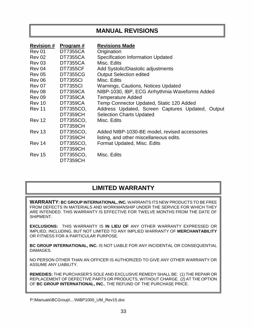
LIMITED WARRANTY
Revision # Program # Revisions Made Rev 01 DT7355CA Origination Rev 02 DT7355CA Specification Information Updated Rev 03 DT7355CA Misc. Edits Rev 04 DT7355CF Add Systolic/Diastolic adjustments Rev 05 DT7355CG Output Selection edited Rev 06 DT7355CI Misc. Edits Rev 07 DT7355CI Warnings, Cautions, Notices Updated Rev 08 DT7359CA NIBP-1030, IBP, ECG Arrhythmia Waveforms Added Rev 09 DT7359CA Temperature Added Rev 10 DT7359CA Temp Connector Updated, Static 120 Added Rev 11 DT7355CO, Address Updated, Screen Captures Updated, Output DT7359CH Selection Charts Updated Rev 12 DT7355CO, Misc. Edits DT7359CH Rev 13 DT7355CO, Added NIBP-1030-BE model, revised accessories DT7359CH listing, and other miscellaneous edits. Rev 14 DT7355CO, Format Updated, Misc. Edits DT7359CH Rev 15 DT7355CO, Misc. Edits DT7359CH
P:\Manuals\BCGroup\…\NIBP1000_UM_Rev15.doc
MANUAL REVISIONS
WARRANTY: BC GROUP INTERNATIONAL, INC. WARRANTS ITS NEW PRODUCTS TO BE FREE
FROM DEFECTS IN MATERIALS AND WORKMANSHIP UNDER THE SERVICE FOR WHICH THEY ARE INTENDED. THIS WARRANTY IS EFFECTIVE FOR TWELVE MONTHS FROM THE DATE OF SHIPMENT.
EXCLUSIONS: THIS WARRANTY IS IN LIEU OF ANY OTHER WARRANTY EXPRESSED OR
IMPLIED, INCLUDING, BUT NOT LIMITED TO ANY IMPLIED WARRANTY OF MERCHANTABILITY OR FITNESS FOR A PARTICULAR PURPOSE.
BC GROUP INTERNATIONAL, INC. IS NOT LIABLE FOR ANY INCIDENTAL OR CONSEQUENTIAL DAMAGES. NO PERSON OTHER THAN AN OFFICER IS AUTHORIZED TO GIVE ANY OTHER WARRANTY OR ASSUME ANY LIABILITY.
REMEDIES: THE PURCHASER'S SOLE AND EXCLUSIVE REMEDY SHALL BE: (1) THE REPAIR OR REPLACEMENT OF DEFECTIVE PARTS OR PRODUCTS, WITHOUT CHARGE. (2) AT THE OPTION
OF BC GROUP INTERNATIONAL, INC., THE REFUND OF THE PURCHASE PRICE.
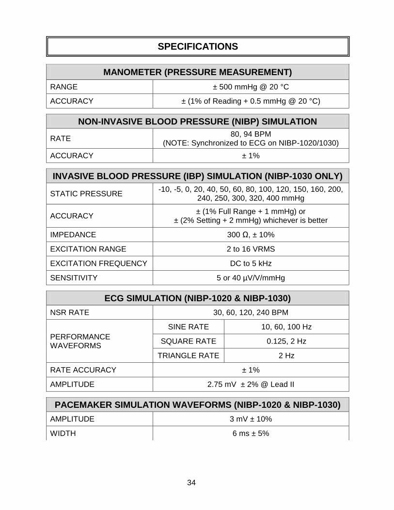
34
MANOMETER (PRESSURE MEASUREMENT)
RANGE ± 500 mmHg @ 20 °C
ACCURACY ± (1% of Reading + 0.5 mmHg @ 20 °C)
NON-INVASIVE BLOOD PRESSURE (NIBP) SIMULATION
RATE 80, 94 BPM
(NOTE: Synchronized to ECG on NIBP-1020/1030)
ACCURACY ± 1%
INVASIVE BLOOD PRESSURE (IBP) SIMULATION (NIBP-1030 ONLY)
STATIC PRESSURE -10, -5, 0, 20, 40, 50, 60, 80, 100, 120, 150, 160, 200,
240, 250, 300, 320, 400 mmHg
ACCURACY ± (1% Full Range + 1 mmHg) or
± (2% Setting + 2 mmHg) whichever is better
IMPEDANCE 300 Ω, ± 10%
EXCITATION RANGE 2 to 16 VRMS
EXCITATION FREQUENCY DC to 5 kHz
SENSITIVITY 5 or 40 µV/V/mmHg
ECG SIMULATION (NIBP-1020 & NIBP-1030)
NSR RATE 30, 60, 120, 240 BPM
PERFORMANCE WAVEFORMS
SINE RATE 10, 60, 100 Hz
SQUARE RATE 0.125, 2 Hz
TRIANGLE RATE 2 Hz
RATE ACCURACY ± 1%
AMPLITUDE 2.75 mV ± 2% @ Lead II
PACEMAKER SIMULATION WAVEFORMS (NIBP-1020 & NIBP-1030)
AMPLITUDE 3 mV ± 10%
WIDTH 6 ms ± 5%
SPECIFICATIONS
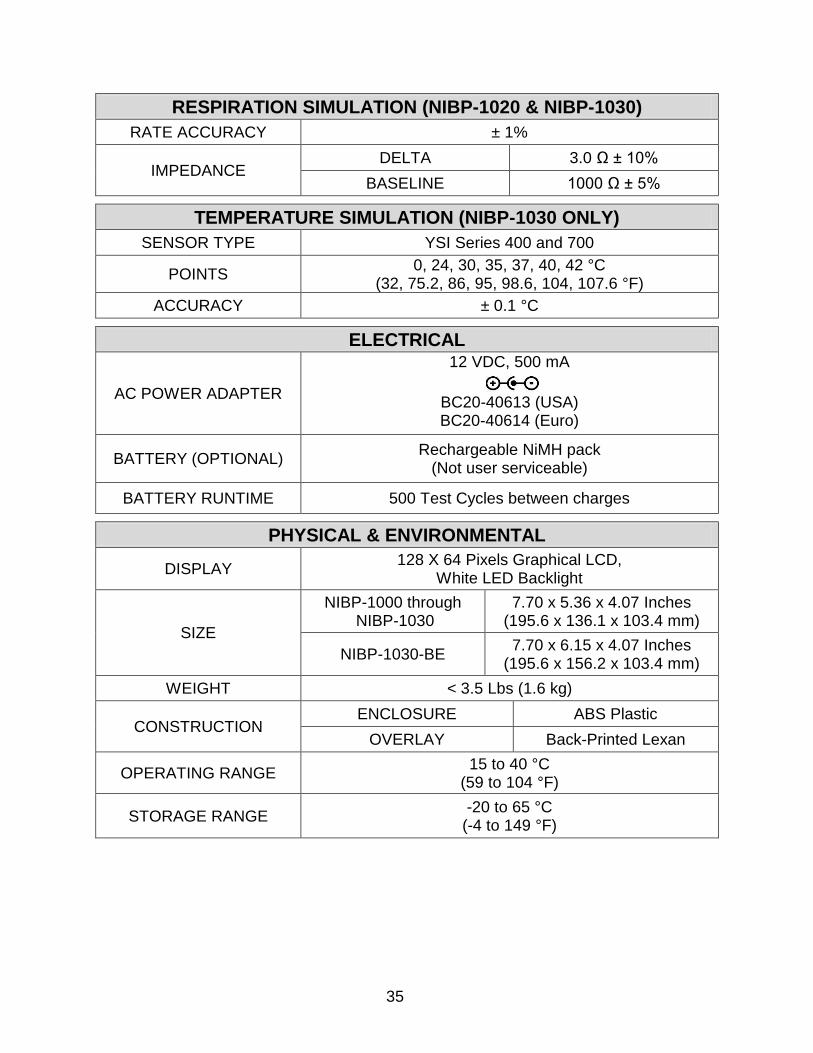
35
RESPIRATION SIMULATION (NIBP-1020 & NIBP-1030)
RATE ACCURACY ± 1%
IMPEDANCE DELTA 3.0 Ω ± 10%
BASELINE 1000 Ω ± 5%
TEMPERATURE SIMULATION (NIBP-1030 ONLY)
SENSOR TYPE YSI Series 400 and 700
POINTS 0, 24, 30, 35, 37, 40, 42 °C
(32, 75.2, 86, 95, 98.6, 104, 107.6 °F)
ACCURACY ± 0.1 °C
ELECTRICAL
AC POWER ADAPTER
12 VDC, 500 mA
BC20-40613 (USA) BC20-40614 (Euro)
BATTERY (OPTIONAL) Rechargeable NiMH pack
(Not user serviceable)
BATTERY RUNTIME 500 Test Cycles between charges
PHYSICAL & ENVIRONMENTAL
DISPLAY 128 X 64 Pixels Graphical LCD,
White LED Backlight
SIZE
NIBP-1000 through NIBP-1030
7.70 x 5.36 x 4.07 Inches (195.6 x 136.1 x 103.4 mm)
NIBP-1030-BE 7.70 x 6.15 x 4.07 Inches
(195.6 x 156.2 x 103.4 mm)
WEIGHT < 3.5 Lbs (1.6 kg)
CONSTRUCTION ENCLOSURE ABS Plastic
OVERLAY Back-Printed Lexan
OPERATING RANGE 15 to 40 °C
(59 to 104 °F)
STORAGE RANGE -20 to 65 °C
(-4 to 149 °F)

36
NOTES

37
NOTES

38
NOTES


BC GROUP INTERNATIONAL, INC.
3081 ELM POINT INDUSTRIAL DRIVE
ST. CHARLES, MO 63301
USA
1-800-242-8428
1-314-638-3800
www.bcgroupintl.com
NIBP Series User Manual
08/12 – Rev 15
Copyright © 2012
Made in the USA