nissan r35 gtr front mounted intercooler ......nissan r35 gtr front mounted intercooler installation...
TRANSCRIPT
NISSAN R35 GTR FRONT MOUNTED
INTERCOOLER INSTALLATION
TOOLS NEEDED
7mm hose clamp driver
10mm/12mm/13mm socket and 3/8” or ¼” ratchet with extensions
Small and large flat blade screwdriver
After installation of this intercooler,
you MUST have the car remapped by
either Cobb Accessport or EcuTek
software to swap the MAF signals. This
intercooler swaps the banks that each
turbo feeds, meaning that the
intercoolers and pipework can be much
straighter than other solutions on the
market. However the car must be
remapped to accept this. Both Cobb
Accessport and EcuTek have this
function built in.
If you do not have the facitily to do this
then please DO NOT continue with the
installation.
1. Position the car ideally on a 2 post lift, or jack it up using the middle jacking point under the
engine and support on axle stands at the jacking points on the sills. Removing both front
road wheels and arch liners may make installation easier but it’s not necessary.
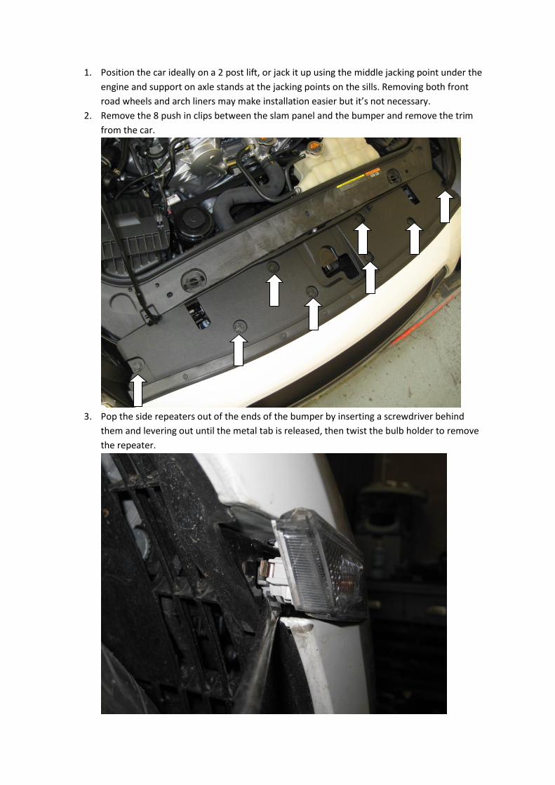
2. Remove the 8 push in clips between the slam panel and the bumper and remove the trim
from the car.
3. Pop the side repeaters out of the ends of the bumper by inserting a screwdriver behind
them and levering out until the metal tab is released, then twist the bulb holder to remove
the repeater.
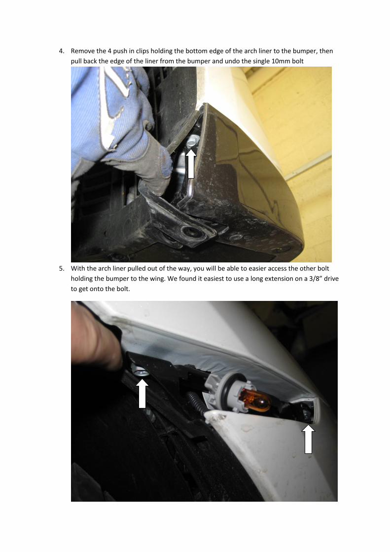
4. Remove the 4 push in clips holding the bottom edge of the arch liner to the bumper, then
pull back the edge of the liner from the bumper and undo the single 10mm bolt
5. With the arch liner pulled out of the way, you will be able to easier access the other bolt
holding the bumper to the wing. We found it easiest to use a long extension on a 3/8” drive
to get onto the bolt.

6. Remove the rubber bungs along the front edge of the bumper (10), and the attached
undertray (4 at the front, 3 at the rear). You’ll notice under the rubber that there is a small
slot to enable you to use a small screwdriver to prise them out.

7. Remove the 10mm bolt under each bung. You’ll notice that the three bolts at the front of
the attached undertray are 12mm, leave these until last. Support the weight of the
undertray and remove the 12mm bolts then pull the undertray forwards to release it from
the locating lugs at the back and remove it from the car.
Locating lugs
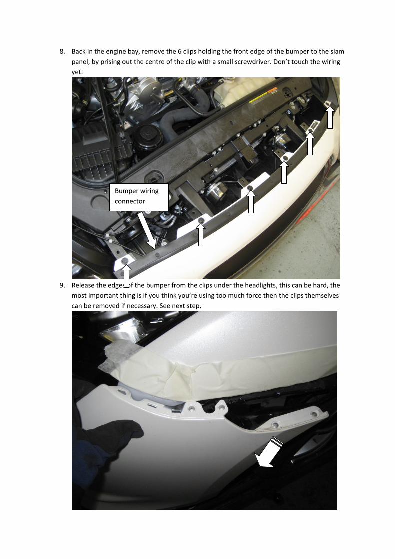
8. Back in the engine bay, remove the 6 clips holding the front edge of the bumper to the slam
panel, by prising out the centre of the clip with a small screwdriver. Don’t touch the wiring
yet.
9. Release the edges of the bumper from the clips under the headlights, this can be hard, the
most important thing is if you think you’re using too much force then the clips themselves
can be removed if necessary. See next step.
Bumper wiring
connector
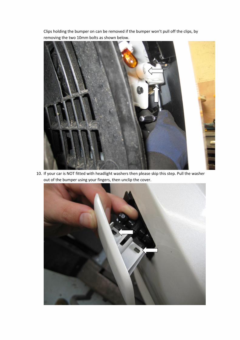
Clips holding the bumper on can be removed if the bumper won’t pull off the clips, by
removing the two 10mm bolts as shown below.
10. If your car is NOT fitted with headlight washers then please skip this step. Pull the washer
out of the bumper using your fingers, then unclip the cover.
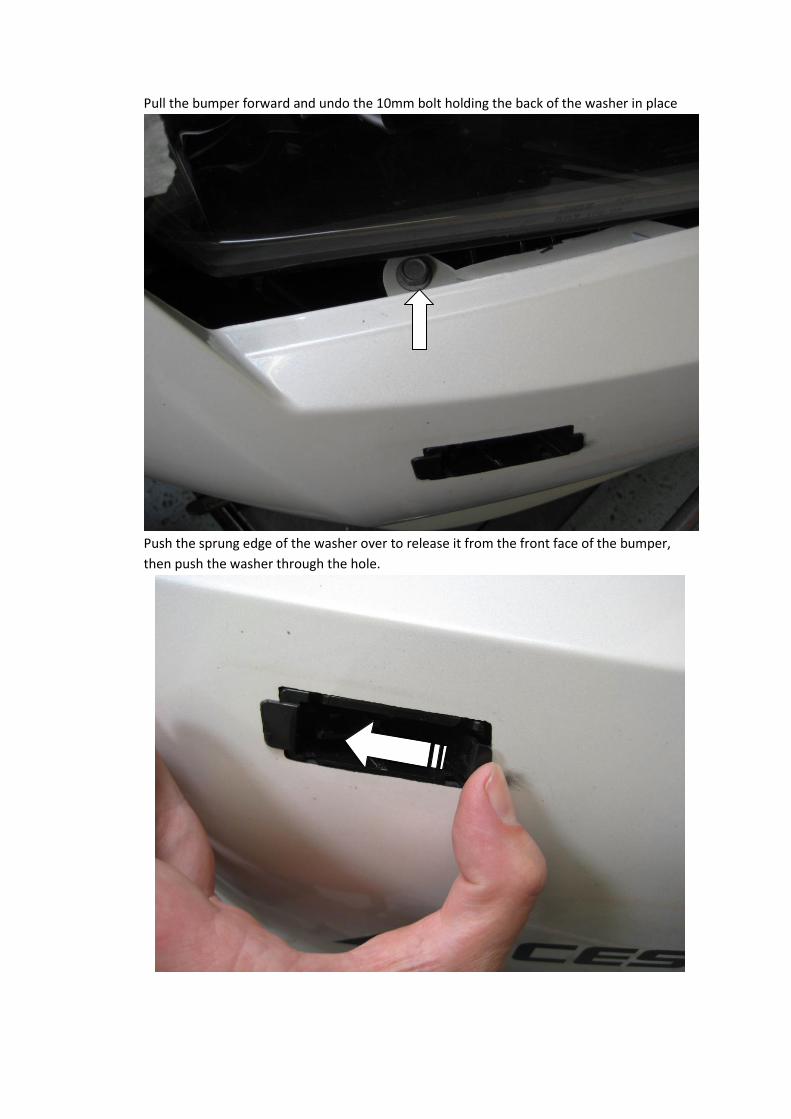
Pull the bumper forward and undo the 10mm bolt holding the back of the washer in place
Push the sprung edge of the washer over to release it from the front face of the bumper,
then push the washer through the hole.
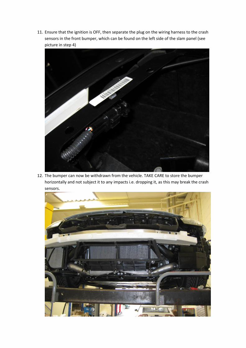
11. Ensure that the ignition is OFF, then separate the plug on the wiring harness to the crash
sensors in the front bumper, which can be found on the left side of the slam panel (see
picture in step 4)
12. The bumper can now be withdrawn from the vehicle. TAKE CARE to store the bumper
horizontally and not subject it to any impacts i.e. dropping it, as this may break the crash
sensors.
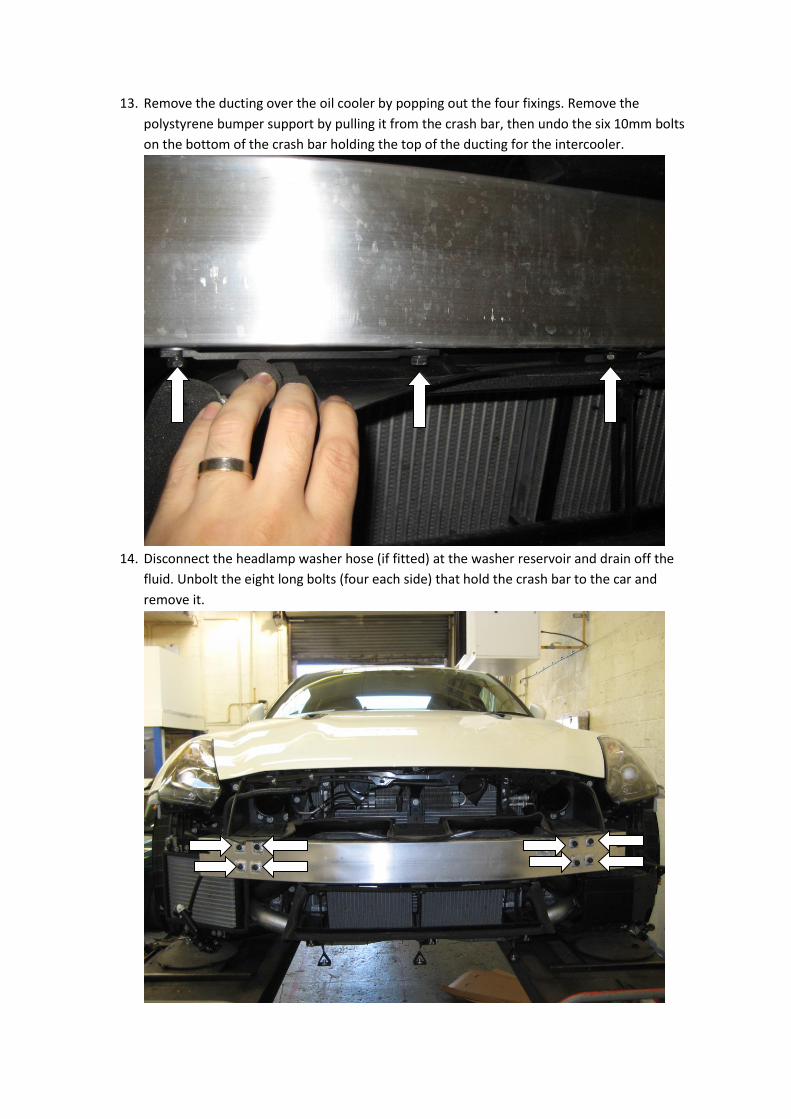
13. Remove the ducting over the oil cooler by popping out the four fixings. Remove the
polystyrene bumper support by pulling it from the crash bar, then undo the six 10mm bolts
on the bottom of the crash bar holding the top of the ducting for the intercooler.
14. Disconnect the headlamp washer hose (if fitted) at the washer reservoir and drain off the
fluid. Unbolt the eight long bolts (four each side) that hold the crash bar to the car and
remove it.

15. Remove the three supports that pass through the intercooler ducting noting their
orientation on the brackets.
16. Disconnect both bottom intercooler hoses. Remove both top intercooler hoses from the
intercoolers to enable access to the rivets holding the intercooler ducting. Remove the
heads of the rivets with a chisel or similar, then remove the ducting from the intercooler.

17. Remove the two bolts holding the intercooler inlet pipes to the chassis, the two bolts on the
edges of the intercoolers (in the middle of the car) and one of the two top bolts of each
intercooler (use a ratchet spanner), leaving one upper bolt to hold the intercoolers in.
The lower intercooler bolts are behind the radiator plastic cowl – to save removing the
whole cowl, undo the lowest six 10mm bolts on the cowl (four across the bottom, and the
lowest of the bolts on each side). You now have access to hold the plastic cowl out of the
way whilst you undo the lower four intercooler bolts with a ratchet spanner. Remove the
intercoolers and replace the bolts on the cowl. RETAIN the intercooler bolts for later use.

18. Remove the rubber hoses from the turbo outlets on the left and right.
19. Remove the stock washer bottle, by first draining the fluid from the bottle into a suitable
container, then undoing the wiring to the level sensor (bottom of bottle), windscreen
washer pump (back of bottle) and headlamp washer pump (if fitted – right side of bottle).
Remove the pipework to the windscreen washer pump and undo (AND KEEP) the bolts
holding the bottle to the car. The filler on the top is a push fit and is a tight fit, so you may
need to support the portion in the car to prevent it breaking.
20. Working in the engine bay, remove the upper portions of the boost pipework, by undoing
the two jubilee clips on the throttle body, and the jubilee clip nearest the air filter. Unlcip
and remove the dump valve outlet pipe and the dump valve vacuum feed. Remove the
wiring to the pressure sensor, and the wiring harness that is attached to the pipe. Remove
the upper pipe complete from the car leaving just the rubber hose behind the air filter, then
separate the dump valve and pressure sensor for later use. Repeat for both sides of the car.
Remove wiring
Remove
Remove
Undo
Undo
Undo
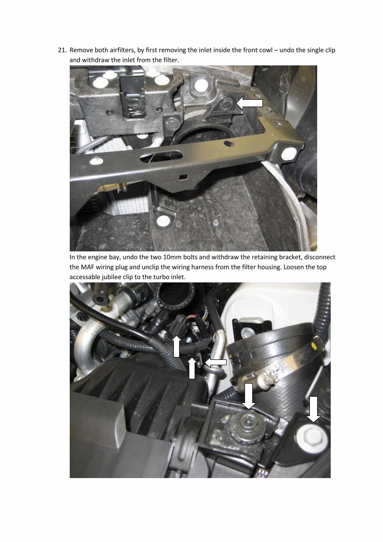
21. Remove both airfilters, by first removing the inlet inside the front cowl – undo the single clip
and withdraw the inlet from the filter.
In the engine bay, undo the two 10mm bolts and withdraw the retaining bracket, disconnect
the MAF wiring plug and unclip the wiring harness from the filter housing. Loosen the top
accessable jubilee clip to the turbo inlet.

Remove the bolt that secures the earthing cable to the engine block, and the clip holding the
wiring to the block which will allow you to pull up the filter housing sharply to release it from
the rubber grommets securing it to the chassis. Repeat for both filters.
Grommet holding filter
to chassis (there are two)

22. Remove the remainder of the pipework inside the engine bay by undoing the three bolts on
each side that secure the pipework to the chassis legs. Withdraw the pipework upwards
through the engine bay.
This is the end of disassembly – at this point you should have:
- Removed the front bumper and lower front undertray
- Removed both intercoolers with ducting
- Removed all pipework from the turbo outlets to the throttle body, and removed the
dump valves and pressure sensors from them
- Removed both airfilters complete with air flow meters
If not, please read back through the instructions so far and complete the list above.
Installation
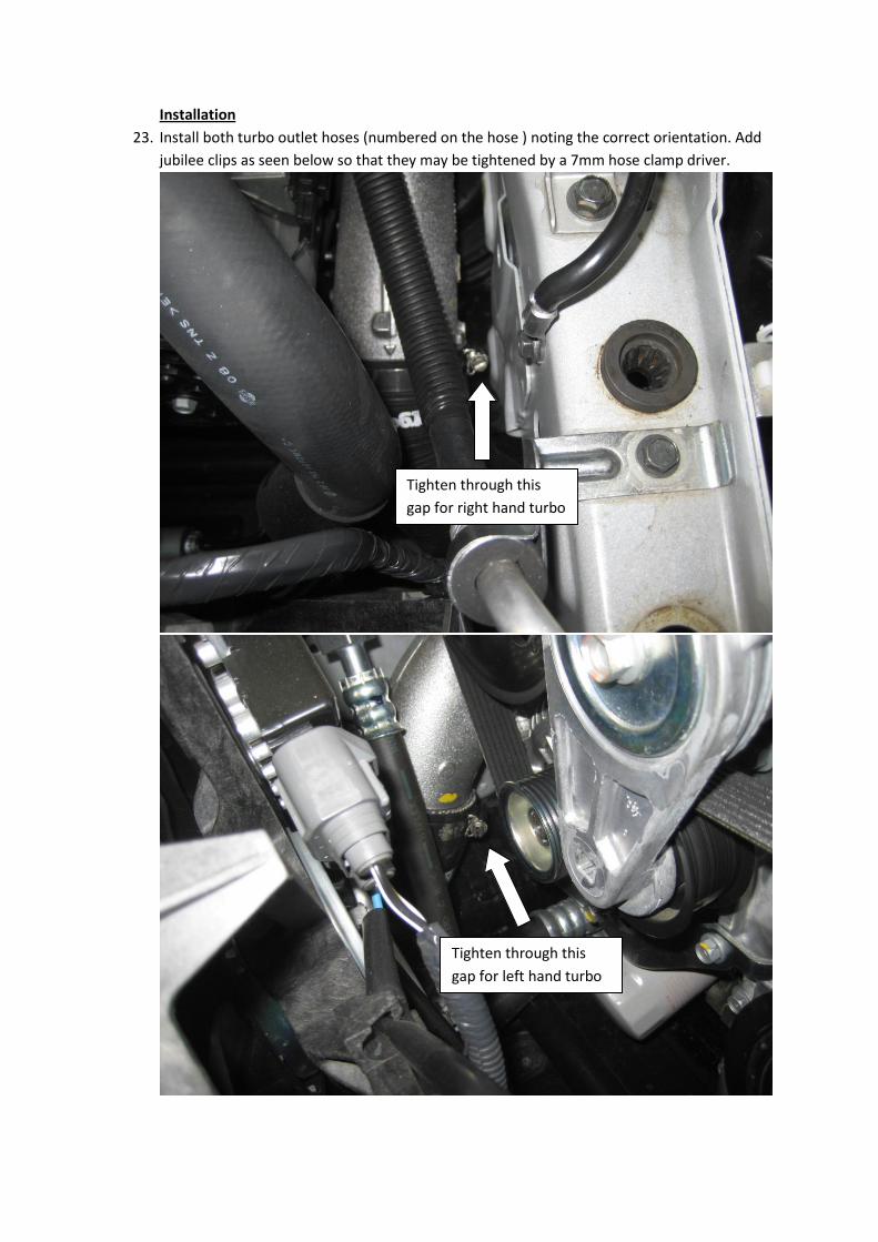
23. Install both turbo outlet hoses (numbered on the hose ) noting the correct orientation. Add
jubilee clips as seen below so that they may be tightened by a 7mm hose clamp driver.
Tighten through this
gap for right hand turbo
Tighten through this
gap for left hand turbo
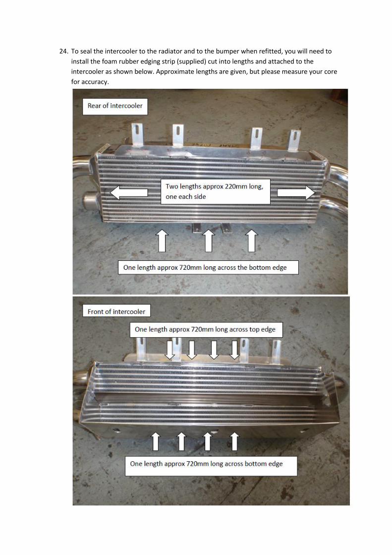
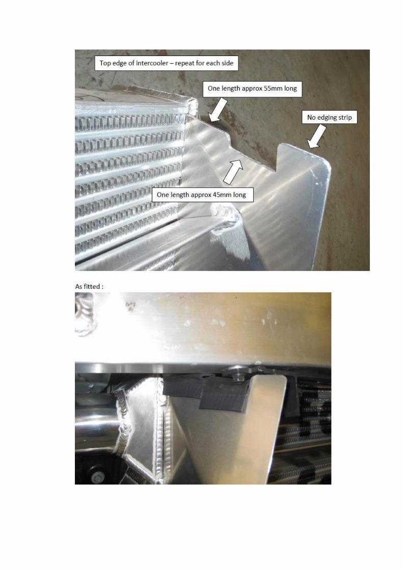
24. To seal the intercooler to the radiator and to the bumper when refitted, you will need to
install the foam rubber edging strip (supplied) cut into lengths and attached to the
intercooler as shown below. Approximate lengths are given, but please measure your core
for accuracy.
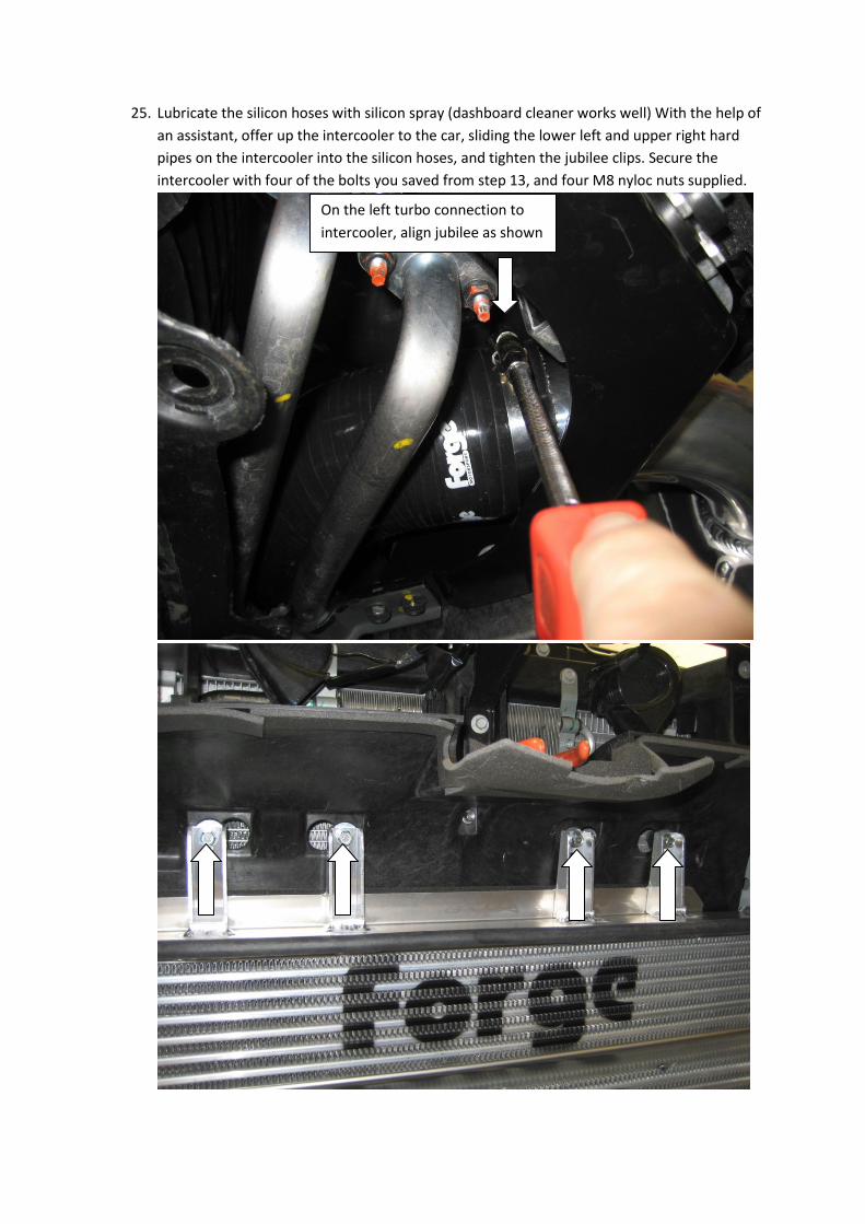
25. Lubricate the silicon hoses with silicon spray (dashboard cleaner works well) With the help of
an assistant, offer up the intercooler to the car, sliding the lower left and upper right hard
pipes on the intercooler into the silicon hoses, and tighten the jubilee clips. Secure the
intercooler with four of the bolts you saved from step 13, and four M8 nyloc nuts supplied.
On the left turbo connection to
intercooler, align jubilee as shown

With the help of an assistant, push the bottom of the intercooler into the car to crush the
rubber seal, and keeping the pressure on tighten with the last two bolts and M8 nyloc nuts.
This rubber seal needs to be compressed and sealed against the cowl all the way down
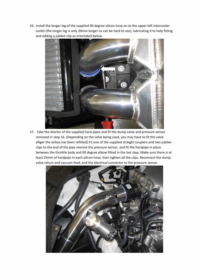
26. Install the longer leg of the supplied 90 degree silicon hose on to the upper left intercooler
outlet (the longer leg is only 20mm longer so can be hard to see), lubricating it to help fitting
and adding a jubilee clip as orientated below
27. Take the shorter of the supplied hard pipes and fit the dump valve and pressure sensor
removed in step 16. (Depending on the valve being used, you may have to fit the valve
aftger the airbox has been refitted).Fit one of the supplied straight couplers and two jubilee
clips to the end of the pipe nearest the pressure sensor, and fit the hardpipe in place
between the throttle body and 90 degree elbow fitted in the last step. Make sure there is at
least 25mm of hardpipe in each silicon hose, then tighten all the clips. Reconnect the dump
valve return and vacuum feed, and the electrical connector to the pressure sensor.
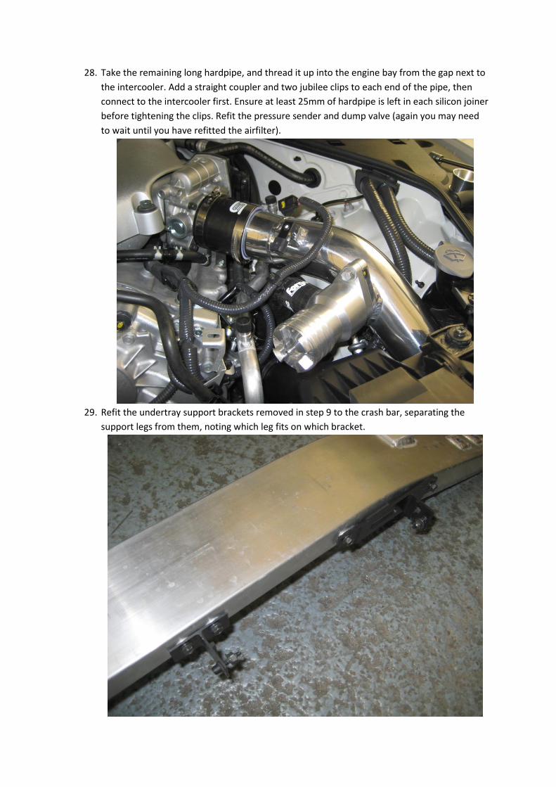
28. Take the remaining long hardpipe, and thread it up into the engine bay from the gap next to
the intercooler. Add a straight coupler and two jubilee clips to each end of the pipe, then
connect to the intercooler first. Ensure at least 25mm of hardpipe is left in each silicon joiner
before tightening the clips. Refit the pressure sender and dump valve (again you may need
to wait until you have refitted the airfilter).
29. Refit the undertray support brackets removed in step 9 to the crash bar, separating the
support legs from them, noting which leg fits on which bracket.
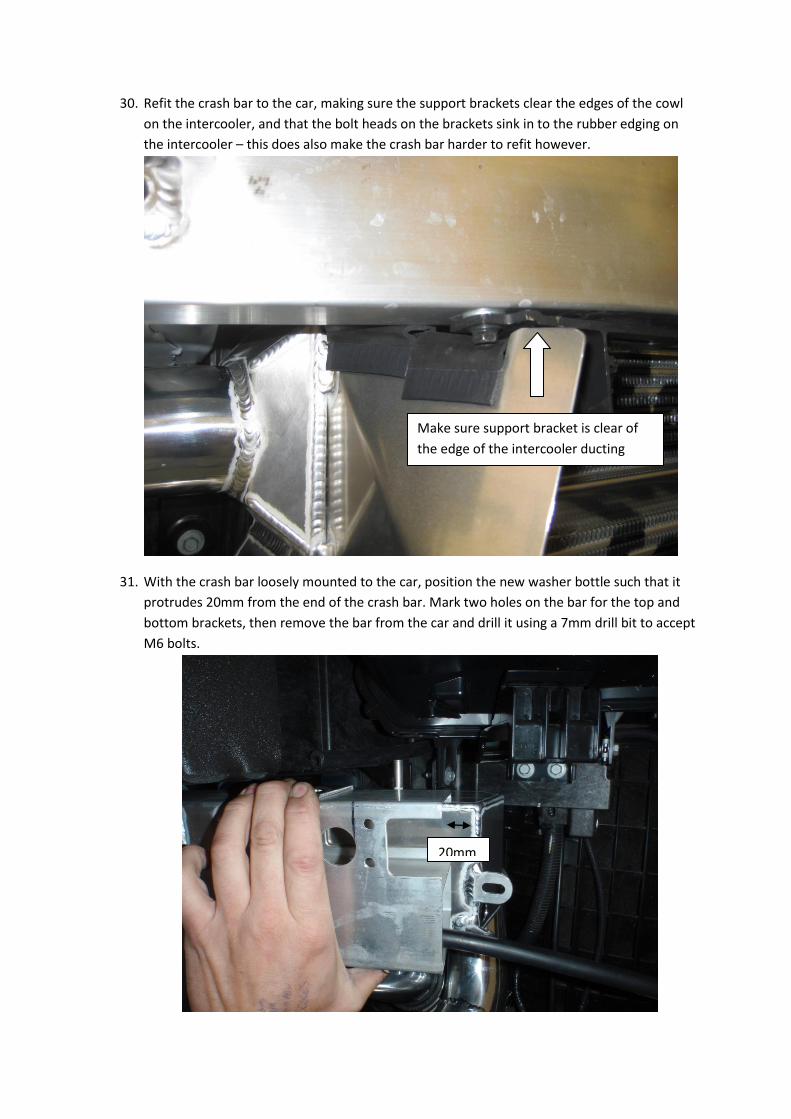
30. Refit the crash bar to the car, making sure the support brackets clear the edges of the cowl
on the intercooler, and that the bolt heads on the brackets sink in to the rubber edging on
the intercooler – this does also make the crash bar harder to refit however.
31. With the crash bar loosely mounted to the car, position the new washer bottle such that it
protrudes 20mm from the end of the crash bar. Mark two holes on the bar for the top and
bottom brackets, then remove the bar from the car and drill it using a 7mm drill bit to accept
M6 bolts.
20mm
Make sure support bracket is clear of
the edge of the intercooler ducting
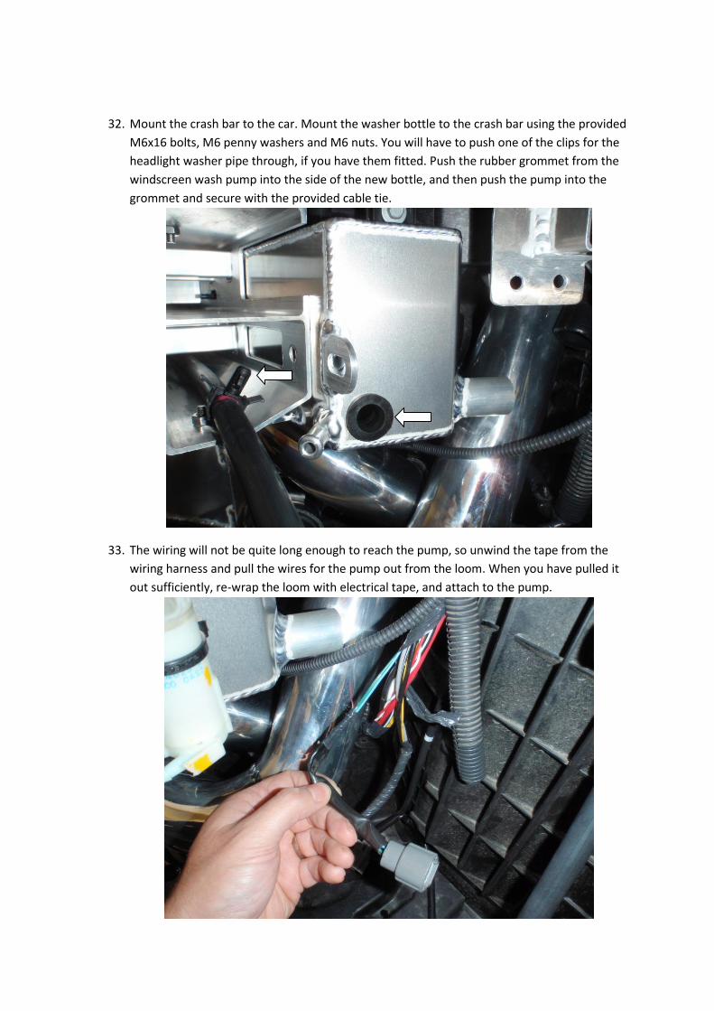
32. Mount the crash bar to the car. Mount the washer bottle to the crash bar using the provided
M6x16 bolts, M6 penny washers and M6 nuts. You will have to push one of the clips for the
headlight washer pipe through, if you have them fitted. Push the rubber grommet from the
windscreen wash pump into the side of the new bottle, and then push the pump into the
grommet and secure with the provided cable tie.
33. The wiring will not be quite long enough to reach the pump, so unwind the tape from the
wiring harness and pull the wires for the pump out from the loom. When you have pulled it
out sufficiently, re-wrap the loom with electrical tape, and attach to the pump.

34. If you DONT have headlamp washer fitted, use the provided 10mm silicon tube and 10mm
blanking plug to blank off the lower port on the washer bottle, then please skip to the next
step. If you DO have headlight washers fitted, mount the pump to the provided p-clip after
wrapping it around the intercooler pipe as shown. Cut the supplied 10mm silicon to length
joining the pump to the bottom of the washer bottle.
35. When everything is fitted correctly, use the supplied 16mm jubilee clips to clamp the ends
of the 10mm silicon hose. Connect the electrical connectors on the headlamp washer and
windscreen washer. Hook up the windscreen washer tube to the washer pump. Hopefully
now your setup should resemble this.

36. Run a breather pipe using the 8mm silicon provided, from up in the engine bay near the filler
cap, down behind the headlight and connect it to the top of the washer bottle. Use the cable
ties provided to keep the breather in place.
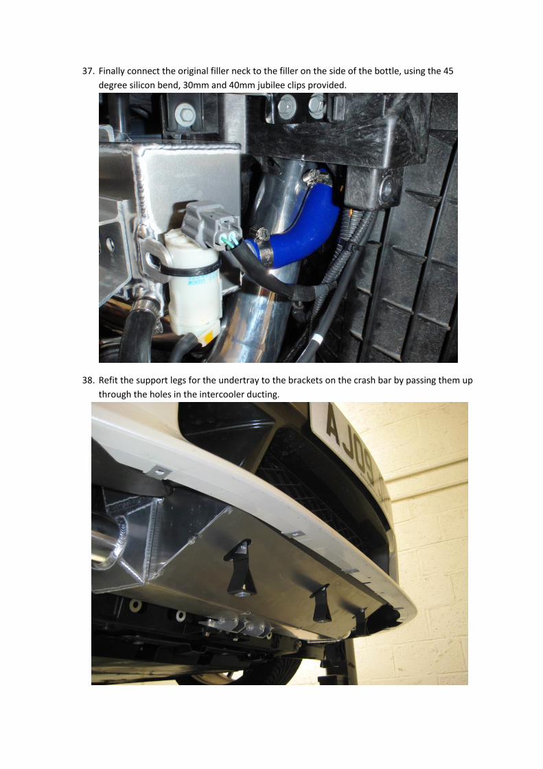
37. Finally connect the original filler neck to the filler on the side of the bottle, using the 45
degree silicon bend, 30mm and 40mm jubilee clips provided.
38. Refit the support legs for the undertray to the brackets on the crash bar by passing them up
through the holes in the intercooler ducting.

39. Refit the ducting over the oil cooler removed in step 13. Refill the washer bottle making sure
there are no leaks from the grommets holding the motor(s) to the bottle.
40. Do a final check of all hoses, then start the car and make sure it idles and runs normally.
When you’re happy, remount the bumper to the car with the help of an assistant following
steps 12-2 in reverse order. You may need to flex the bottom of the grille on the bumper
downwards to help refitting, so that it sits inside the intercooler ducting when the bumper is
in the correct position.
The installation is complete – enjoy your new purchase !
ENGINEERED FOR PERFORMANCE