ni 9485 datasheet - national instruments · measurement category ii is for measurements performed...
TRANSCRIPT
DATASHEET
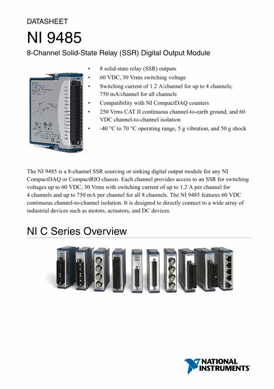
NI 94858-Channel Solid-State Relay (SSR) Digital Output Module
• 8 solid-state relay (SSR) outputs• 60 VDC, 30 Vrms switching voltage• Switching current of 1.2 A/channel for up to 4 channels;
750 mA/channel for all channels• Compatibility with NI CompactDAQ counters• 250 Vrms CAT II continuous channel-to-earth ground, and 60
VDC channel-to-channel isolation• -40 °C to 70 °C operating range, 5 g vibration, and 50 g shock
The NI 9485 is a 8-channel SSR sourcing or sinking digital output module for any NICompactDAQ or CompactRIO chassis. Each channel provides access to an SSR for switchingvoltages up to 60 VDC, 30 Vrms with switching current of up to 1.2 A per channel for4 channels and up to 750 mA per channel for all 8 channels. The NI 9485 features 60 VDCcontinuous channel-to-channel isolation. It is designed to directly connect to a wide array ofindustrial devices such as motors, actuators, and DC devices.
NI C Series Overview
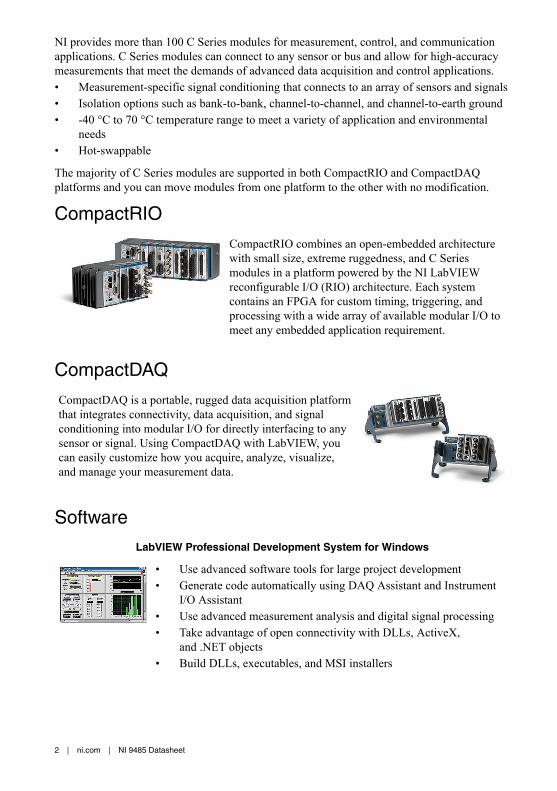
NI provides more than 100 C Series modules for measurement, control, and communicationapplications. C Series modules can connect to any sensor or bus and allow for high-accuracymeasurements that meet the demands of advanced data acquisition and control applications.• Measurement-specific signal conditioning that connects to an array of sensors and signals• Isolation options such as bank-to-bank, channel-to-channel, and channel-to-earth ground• -40 °C to 70 °C temperature range to meet a variety of application and environmental
needs• Hot-swappable
The majority of C Series modules are supported in both CompactRIO and CompactDAQplatforms and you can move modules from one platform to the other with no modification.
CompactRIO
CompactRIO combines an open-embedded architecturewith small size, extreme ruggedness, and C Seriesmodules in a platform powered by the NI LabVIEWreconfigurable I/O (RIO) architecture. Each systemcontains an FPGA for custom timing, triggering, andprocessing with a wide array of available modular I/O tomeet any embedded application requirement.
CompactDAQ
CompactDAQ is a portable, rugged data acquisition platformthat integrates connectivity, data acquisition, and signalconditioning into modular I/O for directly interfacing to anysensor or signal. Using CompactDAQ with LabVIEW, youcan easily customize how you acquire, analyze, visualize,and manage your measurement data.
Software
LabVIEW Professional Development System for Windows
• Use advanced software tools for large project development• Generate code automatically using DAQ Assistant and Instrument
I/O Assistant• Use advanced measurement analysis and digital signal processing• Take advantage of open connectivity with DLLs, ActiveX,
and .NET objects• Build DLLs, executables, and MSI installers
2 | ni.com | NI 9485 Datasheet

NI LabVIEW FPGA Module
• Design FPGA applications for NI RIO hardware• Program with the same graphical environment used for desktop and
real-time applications• Execute control algorithms with loop rates up to 300 MHz• Implement custom timing and triggering logic, digital protocols, and
DSP algorithms• Incorporate existing HDL code and third-party IP including Xilinx IP
generator functions• Purchase as part of the LabVIEW Embedded Control and Monitoring
Suite
NI LabVIEW Real-Time Module
• Design deterministic real-time applications with LabVIEWgraphical programming
• Download to dedicated NI or third-party hardware for reliableexecution and a wide selection of I/O
• Take advantage of built-in PID control, signal processing, andanalysis functions
• Automatically take advantage of multicore CPUs or setprocessor affinity manually
• Take advantage of real-time OS, development and debuggingsupport, and board support
• Purchase individually or as part of a LabVIEW suite
NI 9485 SpecificationsThe following specifications are typical for the range -40 °C to 70 °C unless otherwise noted.
Caution To ensure the specified EMC performance, operate this product only withshielded cables and accessories.
Caution Do not operate the NI 9485 in a manner not specified in this document.Product misuse can result in a hazard. You can compromise the safety protectionbuilt into the product if the product is damaged in any way. If the product isdamaged, return it to NI for repair.
Output CharacteristicsNumber of channels 8 digital output channels
Relay type Normally open solid-state relay (SSR)
Switching voltage 60 VDC max, 30 Vrms max
NI 9485 Datasheet | © National Instruments | 3

Switching current, per channel1
All channels 0.75 A max
Up to four channels 1.2 A max
Switching rate (90% duty cycle)1 1 operation per second
Relay open time 0.5 ms typ
Relay close time 9.0 ms typ
On resistance 200 mΩ max
Off stage leakage 30 μA typ
MTBF 2,172,740 hours at 25 °C; Bellcore Issue 6,Method 1, Case 3, Limited Part Stress Method
Power RequirementsPower consumption from chassis
Active mode 500 mW max
Sleep mode 5 mW max
Thermal dissipation (at 70 °C)
Active mode 1.5 W max
Sleep mode 5 mW max
Physical CharacteristicsIf you need to clean the module, wipe it with a dry towel.
Tip For two-dimensional drawings and three-dimensional models of the C Seriesmodule and connectors, visit ni.com/dimensions and search by module number.
Screw-terminal wiring
Gauge 0.05 mm2 to 1.5 mm2 (30 AWG to 14 AWG)copper conductor wire
Wire strip length 6 mm (0.24 in.) of insulation stripped from theend
Temperature rating 90 °C minimum
Torque for screw terminals 0.22 N · m to 0.25 N · m (1.95 lb · in. to2.21 lb · in.)
1 For additional specifications related to faster switching rates and/or higher currents at lowertemperatures, go to ni.com/info and enter the info code rd9485specs.
4 | ni.com | NI 9485 Datasheet

Wires per screw terminal One wire per screw terminal; two wires perscrew terminal using a 2-wire ferrule
Ferrules 0.25 mm2 to 1.5 mm2
Connector securement
Securement type Screw flanges provided
Torque for screw flanges 0.2 N · m (1.80 lb · in.)
Weight 145 g (5.1 oz)
Safety VoltagesConnect only voltages that are within the following limits.
Maximum voltage, Channel a to Channel b 60 VDC, 30 Vrms
Isolation
Channel-to-channel (up to 5,000 m)
Continuous 60 VDC, Measurement Category I
Withstand 1,000 Vrms, verified by a 5 s dielectricwithstand test
Channel-to-earth ground (up to 2,000 m)
Continuous 250 Vrms, Measurement Category II
Withstand 2,300 Vrms, verified by a 5 s dielectricwithstand test
Channel-to-earth ground (up to 5,000 m)
Continuous 60 VDC, Measurement Category I
Withstand 1,000 Vrms, verified by a 5 s dielectricwithstand test
Measurement Category I is for measurements performed on circuits not directly connected tothe electrical distribution system referred to as MAINS voltage. MAINS is a hazardous liveelectrical supply system that powers equipment. This category is for measurements of voltagesfrom specially protected secondary circuits. Such voltage measurements include signal levels,special equipment, limited-energy parts of equipment, circuits powered by regulated low-voltage sources, and electronics.
Caution Do not connect the NI 9485 to signals or use for measurements withinMeasurement Categories II, III, or IV.
Note Measurement Categories CAT I and CAT O are equivalent. These test andmeasurement circuits are not intended for direct connection to the MAINS buildinginstallations of Measurement Categories CAT II, CAT III, or CAT IV.
NI 9485 Datasheet | © National Instruments | 5

Measurement Category II is for measurements performed on circuits directly connected to theelectrical distribution system. This category refers to local-level electrical distribution, such asthat provided by a standard wall outlet, for example, 115 V for U.S. or 230 V for Europe.
Caution Do not connect the NI 9485 to signals or use for measurements withinMeasurement Categories III or IV.
Safety Guidelines for Hazardous LocationsThe NI 9485 is suitable for use in Class I, Division 2, Groups A, B, C, D, T4 hazardouslocations; Class I, Zone 2, AEx nA IIC T4 and Ex nA IIC T4 hazardous locations; andnonhazardous locations only. Follow these guidelines if you are installing the NI 9485 in apotentially explosive environment. Not following these guidelines may result in serious injuryor death.
Caution Do not disconnect I/O-side wires or connectors unless power has beenswitched off or the area is known to be nonhazardous.
Caution Do not remove modules unless power has been switched off or the area isknown to be nonhazardous.
Caution Substitution of components may impair suitability for Class I, Division 2.
Caution For Division 2 and Zone 2 applications, install the system in an enclosurerated to at least IP54 as defined by IEC/EN 60079-15.
Caution For Division 2 and Zone 2 applications, install a protection device acrossthe positive and negative terminals of the external power supply (or supplies). Thedevice must prevent the external power supply from exceeding 80 V if there is atransient overvoltage condition.
Special Conditions for Hazardous Locations Use in Europe andInternationallyThe NI 9485 has been evaluated as Ex nA IIC T4 Gc equipment under DEMKO CertificateNo. 03 ATEX 0324020X and is IECEx 14.0089X certified. Each NI 9485 is marked II 3Gand is suitable for use in Zone 2 hazardous locations, in ambient temperatures of -40 °C ≤ Ta ≤70 °C. If you are using the NI 9485 in Gas Group IIC hazardous locations, you must use thedevice in an NI chassis that has been evaluated as Ex nC IIC T4, Ex IIC T4, Ex nA IIC T4, orEx nL IIC T4 equipment.
Caution You must make sure that transient disturbances do not exceed 140% ofthe rated voltage.
Caution The system shall only be used in an area of not more than PollutionDegree 2, as defined in IEC 60664-1.
6 | ni.com | NI 9485 Datasheet

Caution The system shall be mounted in an ATEX/IECEx-certified enclosure witha minimum ingress protection rating of at least IP54 as defined in IEC/EN 60079-15.
Caution The enclosure must have a door or cover accessible only by the use of atool.
Safety and Hazardous Locations StandardsThis product is designed to meet the requirements of the following electrical equipment safetystandards for measurement, control, and laboratory use:• IEC 61010-1, EN 61010-1• UL 61010-1, CSA 61010-1• EN 60079-0:2012, EN 60079-15:2010• IEC 60079-0: Ed 6, IEC 60079-15; Ed 4• UL 60079-0; Ed 5, UL 60079-15; Ed 3• CSA 60079-0:2011, CSA 60079-15:2012
Note For UL and other safety certifications, refer to the product label or the OnlineProduct Certification section.
Electromagnetic CompatibilityThis product is designed to meet the requirements of the following standards of EMC forelectrical equipment for measurement, control, and laboratory use:• EN 61326 EMC requirements; Industrial Immunity• EN 55011 Emissions; Group 1, Class A• CE, C-Tick, ICES, and FCC Part 15 Emissions; Class A
Note For EMC compliance, operate this device according to productdocumentation.
CE Compliance This product meets the essential requirements of applicable European Directives, as follows:• 2014/35/EU; Low-Voltage Directive (safety)• 2014/30/EU; Electromagnetic Compatibility Directive (EMC)• 94/9/EC; Potentially Explosive Atmospheres (ATEX)
Online Product CertificationRefer to the product Declaration of Conformity (DoC) for additional regulatory complianceinformation. To obtain product certifications and the DoC for this product, visit ni.com/certification, search by model number or product line, and click the appropriate link in theCertification column.
NI 9485 Datasheet | © National Instruments | 7

Shock and VibrationTo meet these specifications, you must panel mount the system.
Operating vibration
Random (IEC 60068-2-64) 5 grms, 10 Hz to 500 Hz
Sinusoidal (IEC 60068-2-6) 5 g, 10 Hz to 500 Hz
Operating shock (IEC 60068-2-27) 30 g, 11 ms half sine; 50 g, 3 ms half sine;18 shocks at 6 orientations
EnvironmentalRefer to the manual for the chassis you are using for more information about meeting thesespecifications.
Operating temperature(IEC 60068-2-1, IEC 60068-2-2)
-40 °C to 70 °C
Storage temperature(IEC 60068-2-1, IEC 60068-2-2)
-40 °C to 85 °C
Ingress protection IP40
Operating humidity (IEC 60068-2-78) 10% RH to 90% RH, noncondensing
Storage humidity (IEC 60068-2-78) 5% RH to 95% RH, noncondensing
Pollution Degree 2
Maximum altitude 5,000 m
Indoor use only.
Environmental ManagementNI is committed to designing and manufacturing products in an environmentally responsiblemanner. NI recognizes that eliminating certain hazardous substances from our products isbeneficial to the environment and to NI customers.
For additional environmental information, refer to the Minimize Our Environmental Impactweb page at ni.com/environment. This page contains the environmental regulations anddirectives with which NI complies, as well as other environmental information not included inthis document.
Waste Electrical and Electronic Equipment (WEEE)EU Customers At the end of the product life cycle, all NI products must bedisposed of according to local laws and regulations. For more information abouthow to recycle NI products in your region, visit ni.com/environment/weee.
8 | ni.com | NI 9485 Datasheet

电子信息产品污染控制管理办法(中国 RoHS)中国客户 National Instruments 符合中国电子信息产品中限制使用某些有害物
质指令(RoHS)。关于 National Instruments 中国 RoHS 合规性信息,请登录
ni.com/environment/rohs_china。(For information about China RoHScompliance, go to ni.com/environment/rohs_china.)
NI 9485 Datasheet | © National Instruments | 9

Refer to the NI Trademarks and Logo Guidelines at ni.com/trademarks for information on National Instruments trademarks.Other product and company names mentioned herein are trademarks or trade names of their respective companies. For patentscovering National Instruments products/technology, refer to the appropriate location: Help»Patents in your software, thepatents.txt file on your media, or the National Instruments Patent Notice at ni.com/patents. You can find information aboutend-user license agreements (EULAs) and third-party legal notices in the readme file for your NI product. Refer to the ExportCompliance Information at ni.com/legal/export-compliance for the National Instruments global trade compliance policy andhow to obtain relevant HTS codes, ECCNs, and other import/export data. NI MAKES NO EXPRESS OR IMPLIED WARRANTIESAS TO THE ACCURACY OF THE INFORMATION CONTAINED HEREIN AND SHALL NOT BE LIABLE FOR ANY ERRORS.U.S. Government Customers: The data contained in this manual was developed at private expense and is subject to theapplicable limited rights and restricted data rights as set forth in FAR 52.227-14, DFAR 252.227-7014, and DFAR 252.227-7015.
© 2015 National Instruments. All rights reserved.
374820A-02 May15