ni 9234 operating instructions and specifications 9234 operating instructions and specifications...
TRANSCRIPT

OPERATING INSTRUCTIONS AND SPECIFICATIONS
NI 92344-Channel, ±5 V, 24-Bit Software-SelectableIEPE and AC/DC Analog Input Module
ni.com/manuals
DeutschFrançais

NI 9234 Operating Instructions and Specifications 2 ni.com
This document describes how to use the National Instruments 9234 and includes specifications and connector assignments for the NI 9234. Visit ni.com/info and enter rdsoftwareversion to determine which software you need for the modules you are using. For information about installing, configuring, and programming the system, refer to the system documentation. Visit ni.com/info and enter cseriesdoc for information about C Series documentation.
Note The safety guidelines and specifications in this document are specific to the NI 9234. The other components in the system might not meet the same safety ratings and specifications. Refer to the documentation for each component in the system to determine the safety ratings and specifications for the entire system. Visit ni.com/info and enter cseriesdoc for information about C Series documentation.
© National Instruments Corp. 3 NI 9234 Operating Instructions and Specifications
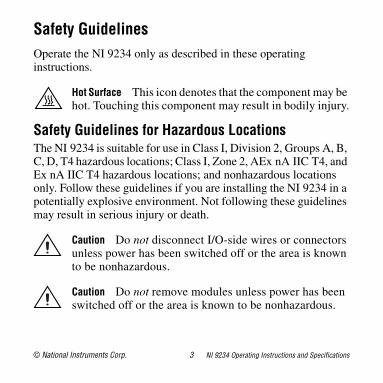
Safety GuidelinesOperate the NI 9234 only as described in these operating instructions.
Hot Surface This icon denotes that the component may be hot. Touching this component may result in bodily injury.
Safety Guidelines for Hazardous LocationsThe NI 9234 is suitable for use in Class I, Division 2, Groups A, B, C, D, T4 hazardous locations; Class I, Zone 2, AEx nA IIC T4, and Ex nA IIC T4 hazardous locations; and nonhazardous locations only. Follow these guidelines if you are installing the NI 9234 in a potentially explosive environment. Not following these guidelines may result in serious injury or death.
Caution Do not disconnect I/O-side wires or connectors unless power has been switched off or the area is known to be nonhazardous.
Caution Do not remove modules unless power has been switched off or the area is known to be nonhazardous.
NI 9234 Operating Instructions and Specifications 4 ni.com
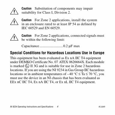
Caution Substitution of components may impair suitability for Class I, Division 2.
Caution For Zone 2 applications, install the system in an enclosure rated to at least IP 54 as defined by IEC 60529 and EN 60529.
Caution For Zone 2 applications, connected signals must be within the following limit:
Capacitance .......................... 0.2 μF max
Special Conditions for Hazardous Locations Use in EuropeThis equipment has been evaluated as Ex nA IIC T4 equipment under DEMKO Certificate No. 07 ATEX 0626664X. Each module is marked II 3G and is suitable for use in Zone 2 hazardous locations. If you are using the NI 9234 in Gas Group IIC hazardous locations or in ambient temperatures of –40 °C ≤ Ta ≤ 70 °C, you must use the device in an NI chassis that has been evaluated as EEx nC IIC T4, Ex nA IIC T4, or Ex nL IIC T4 equipment.

© National Instruments Corp. 5 NI 9234 Operating Instructions and Specifications
Special Conditions for Marine ApplicationsSome modules are Lloyd’s Register (LR) Type Approved for marine applications. To verify Lloyd’s Register certification, visit ni.com/certification and search for the LR certificate, or look for the Lloyd’s Register mark on the module.
Caution To meet radio frequency emission requirements for marine applications, use shielded cables and install the system in a metal enclosure. Suppression ferrites must be installed on power supply inputs near power entries to modules and controllers. Power supply and module cables must be separated on opposite sides of the enclosure and must enter and exit through opposing enclosure walls.

NI 9234 Operating Instructions and Specifications 6 ni.com
Connecting the NI 9234The NI 9234 has four BNC connectors that provide connections to four simultaneously sampled analog input channels.
Figure 1. NI 9234 Connector Assignments
AI3+AI3–
AI2+AI2–
AI0+AI0–
AI1+AI1–

© National Instruments Corp. 7 NI 9234 Operating Instructions and Specifications
Each channel has a BNC connector to which you can connect a signal source. You can also enable excitation current on a per-channel basis to connect Integrated Electronics Piezoelectric (IEPE) sensors. Refer to the NI 9234 Circuitry section for more information. The center pin of the connector, AI+, provides the DC excitation, when enabled, and the positive input signal connection. The shell of the connector, AI–, provides the excitation return path and the signal ground reference.
Connecting Signal Sources to the NI 9234You can connect ground-referenced or floating signal sources to the NI 9234. To avoid picking up ground noise, use a floating connection. To further minimize ground noise, prevent the metal shells of the BNC connectors from coming in contact with each other, the modules, or the chassis.
If you make a ground-referenced connection between the signal source and the NI 9234, make sure the voltage on the AI– shell is in the common-mode range to ensure proper operation of the NI 9234. The AI– shell is protected against accidental contact with overvoltages within the overvoltage protection range. Refer to the Specifications section for more information about operating voltages and overvoltage protection.

NI 9234 Operating Instructions and Specifications 8 ni.com
Refer to Figures 2 and 3 for illustrations of connecting grounded and floating signal sources to the NI 9234.
Figure 2. Connecting a Grounded Signal Source to the NI 9234
NI 9234
AI+
AI–
+
–
SignalSource
CommonModeVoltage

© National Instruments Corp. 9 NI 9234 Operating Instructions and Specifications
Figure 3. Connecting a Floating Signal Source to the NI 9234
The NI 9234 can also provide an IEPE excitation current for each channel to measure ground-referenced or floating IEPE sensors. Typical IEPE sensors have a case that is electrically isolated from the IEPE electronics, so connecting the sensor to the NI 9234 results in a floating connection even though the case of the sensor is grounded.
NI 9234
AI+
AI–
+
–
SignalSource
NI 9234 Operating Instructions and Specifications 10 ni.com
NI 9234 CircuitryThe NI 9234 analog input channels are referenced to chassis ground through a 50 Ω resistor. To minimize ground noise, make sure the chassis ground is connected to earth ground. Each channel is protected from overvoltages. The input signal on each channel is buffered, conditioned, and then sampled by a 24-bit Delta-Sigma ADC. You can configure each channel in software for AC or DC coupling. For channels set to AC coupling, you can turn the IEPE excitation current on or off. Refer to the software help for information about configuring channels on the NI 9234.
© National Instruments Corp. 11 NI 9234 Operating Instructions and Specifications
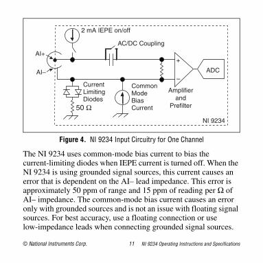
Figure 4. NI 9234 Input Circuitry for One Channel
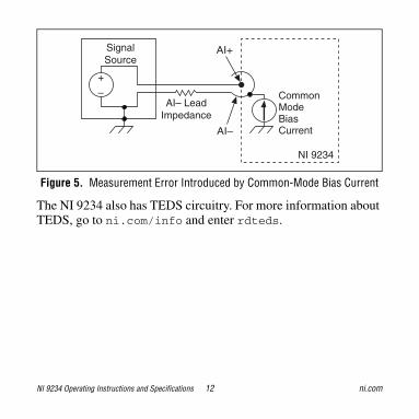
The NI 9234 uses common-mode bias current to bias the current-limiting diodes when IEPE current is turned off. When the NI 9234 is using grounded signal sources, this current causes an error that is dependent on the AI– lead impedance. This error is approximately 50 ppm of range and 15 ppm of reading per Ω of AI– impedance. The common-mode bias current causes an error only with grounded sources and is not an issue with floating signal sources. For best accuracy, use a floating connection or use low-impedance leads when connecting grounded signal sources.
2 mA IEPE on/off
AI+
AI–
Amplifierand
Prefilter
ADC
+
–
AC/DC Coupling
NI 9234
CommonModeBiasCurrent
CurrentLimitingDiodes
50 Ω
NI 9234 Operating Instructions and Specifications 12 ni.com
Figure 5. Measurement Error Introduced by Common-Mode Bias Current
The NI 9234 also has TEDS circuitry. For more information about TEDS, go to ni.com/info and enter rdteds.
NI 9234
AI+
AI–
+
–
SignalSource
AI– LeadImpedance
CommonModeBiasCurrent
© National Instruments Corp. 13 NI 9234 Operating Instructions and Specifications
Understanding NI 9234 FilteringThe NI 9234 uses a combination of analog and digital filtering to provide an accurate representation of in-band signals while rejecting out-of-band signals. The filters discriminate between signals based on the frequency range, or bandwidth, of the signal. The three important bandwidths to consider are the passband, the stopband, and the alias-free bandwidth.
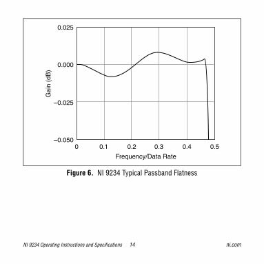
The NI 9234 represents signals within the passband, as quantified primarily by passband flatness and phase nonlinearity. All signals that appear in the alias-free bandwidth are either unaliased signals or signals that have been filtered by at least the amount of the stopband rejection.
PassbandThe signals within the passband have frequency-dependent gain or attenuation. The small amount of variation in gain with respect to frequency is called the passband flatness. The digital filters of the NI 9234 adjust the frequency range of the passband to match the data rate. Therefore, the amount of gain or attenuation at a given frequency depends on the data rate. Figure 6 shows typical passband flatness for the NI 9234.
NI 9234 Operating Instructions and Specifications 14 ni.com
Figure 6. NI 9234 Typical Passband Flatness
Frequency/Data Rate
0.50.4
0.025
0.000
–0.025
–0.0500.30.20.10
Gai
n (d
B)

© National Instruments Corp. 15 NI 9234 Operating Instructions and Specifications
StopbandThe filter significantly attenuates all signals above the stopband frequency. The primary goal of the filter is to prevent aliasing. Therefore, the stopband frequency scales precisely with the data rate. The stopband rejection is the minimum amount of attenuation applied by the filter to all signals with frequencies within the stopband.
Alias-Free BandwidthAny signal that appears in the alias-free bandwidth of the NI 9234 is not an aliased artifact of signals at a higher frequency. The alias-free bandwidth is defined by the ability of the filter to reject frequencies above the stopband frequency, and it is equal to the data rate minus the stopband frequency.

NI 9234 Operating Instructions and Specifications 16 ni.com
Understanding NI 9234 Data RatesThe frequency of a master timebase (fM) controls the data rate (fs) of the NI 9234. The NI 9234 includes an internal master timebase with a frequency of 13.1072 MHz, but the module also can accept an external master timebase or export its own master timebase. To synchronize the data rate of an NI 9234 with other modules that use master timebases to control sampling, all of the modules must share a single master timebase source. Refer to the software help for information about configuring the master timebase source for the NI 9234. Visit ni.com/info and enter cseriesdoc for information about C Series documentation.
The following equation provides the available data rates of the NI 9234:
fs =
where n is any integer from 1 to 31.
However, the data rate must remain within the appropriate data rate range. Refer to the Specifications section for more information about the data rate range. When using the internal master timebase
fM 256÷n
---------------------

© National Instruments Corp. 17 NI 9234 Operating Instructions and Specifications
of 13.1072 MHz, the result is data rates of 51.2 kS/s, 25.6 kS/s, 17.067 kS/s, and so on down to 1.652 kS/s, depending on the value of n. When using an external timebase with a frequency other than 13.1072 MHz, the NI 9234 has a different set of data rates.
Note The cRIO-9151 R Series Expansion chassis does not support sharing timebases between modules.
Sleep ModeThis module supports a low-power sleep mode. Support for sleep mode at the system level depends on the chassis that the module is plugged into. Refer to the chassis manual for information about support for sleep mode. If the chassis supports sleep mode, refer to the software help for information about enabling sleep mode. Visit ni.com/info and enter cseriesdoc for information about C Series documentation.
Typically, when a system is in sleep mode, you cannot communicate with the modules. In sleep mode, the system consumes minimal power and may dissipate less heat than it does in normal mode. Refer to the Specifications section for more information about power consumption and thermal dissipation.

NI 9234 Operating Instructions and Specifications 18 ni.com
SpecificationsThe following specifications are typical for the range –40 to 70 °C unless otherwise noted.
Input CharacteristicsNumber of channels.......................... 4 analog input channels
ADC resolution................................. 24 bits
Type of ADC.....................................Delta-Sigma (with analog prefiltering)
Sampling mode .................................Simultaneous
Type of TEDS supported .................. IEEE 1451.4 TEDS Class I
Internal master timebase (fM)
Frequency ................................... 13.1072 MHzAccuracy..................................... ±50 ppm max
Data rate range (fs) using internal master timebase
Minimum.................................... 1.652 kS/sMaximum ................................... 51.2 kS/s

© National Instruments Corp. 19 NI 9234 Operating Instructions and Specifications
Data rate range (fs) using external master timebase
Minimum.................................... 0.391 kS/sMaximum ................................... 52.734 kS/s
Data rates1 (fs) ................................... , n = 1, 2, …, 31
Input coupling...................................AC/DC (software-selectable)
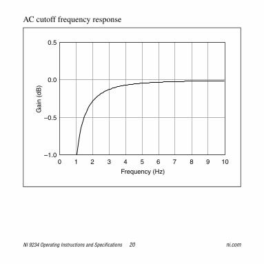
AC cutoff frequency–3 dB .......................................... 0.5 Hz–0.1 dB....................................... 4.6 Hz max
1 The data rate must remain within the appropriate data rate range. Refer to the Understanding NI 9234 Data Rates section for more information.
fM 256÷n
---------------------
NI 9234 Operating Instructions and Specifications 20 ni.com
AC cutoff frequency response
Frequency (Hz)
104
0.5
0.0
–0.5
–1.03210 98765
Gai
n (d
B)

© National Instruments Corp. 21 NI 9234 Operating Instructions and Specifications
Input range ........................................ ±5 V
AC voltage full-scale rangeMinimum.................................... ±5 Vpk
Typical ........................................ ±5.1 Vpk
Maximum ...................................±5.2 Vpk
Common-mode voltage range(AI– to earth ground) ........................±2 V max
IEPE excitation current (software-selectable on/off)Minimum.................................... 2.0 mATypical ........................................ 2.1 mA
Power-on glitch................................. 90 μA for 10 μs

NI 9234 Operating Instructions and Specifications 22 ni.com
IEPE compliance voltage.................. 19 V max
If you are using an IEPE sensor, use the following equation to make sure your configuration meets the IEPE compliance voltage range.
(Vcommon-mode + Vbias ± Vfull-scale) must be 0 to 19
Overvoltage protection (with respect to chassis ground)For a signal source connectedto AI+ and AI– ........................... ±30 VFor a low-impedance sourceconnected to AI+ and AI– .......... –6 to 30 V
Input delay ........................................ 38.4/ fs + 3.2 μs
where Vcommon-mode is the common-mode voltage appliedto the NI 9234
Vbias is the bias voltage of the IEPE sensor
Vfull-scale is the full-scale voltage of the IEPE sensor

© National Instruments Corp. 23 NI 9234 Operating Instructions and Specifications
Accuracy1
1 Refer to the NI 9234 Circuitry section for information regarding grounded signal sources and measurement accuracy.
Measurement Conditions
Percent of Reading
(Gain Error)
Percent of Range*
(Offset Error)
Calibrated max (–40 to 70 °C) 0.34%,±0.03 dB
±0.14%,7.1 mV
Calibrated typ (25 °C ±5 °C) 0.05%,±0.005 dB
±0.006%,0.3 mV
Uncalibrated max (–40 to 70 °C) 1.9%,±0.16 dB
±0.27%,13.9 mV
Uncalibrated typ (25 °C ±5 °C) 0.48%,±0.04 dB
±0.04%,2.3 mV
* Range = 5.1 Vpk

NI 9234 Operating Instructions and Specifications 24 ni.com
Gain driftTypical ........................................ 0.14 mdB/°C (16 ppm/°C)Maximum ................................... 0.45 mdB/°C (52 ppm/°C)
Offset driftTypical ........................................ 19.2 μV/°CMaximum ................................... 118 μV/°C
Channel-to-channel matchingGain
Typical.................................. 0.01 dBMaximum............................. 0.04 dB
Phase ( fin in kHz) ....................... fin · 0.045° + 0.04 max
PassbandFrequency ................................... 0.45 · fsFlatness (fs = 51.2 kS/s).............. ±40 mdB (pk-to-pk max)
Phase nonlinearity(fs = 51.2 kS/s) .................................. ±0.45° max
StopbandFrequency ................................... 0.55 · fsRejection..................................... 100 dB

© National Instruments Corp. 25 NI 9234 Operating Instructions and Specifications
Alias-free bandwidth ........................ 0.45 · fsOversample rate ................................ 64 · fsCrosstalk (1 kHz).............................. –110 dB
CMRR (fin ≤ 1 kHz)Minimum.................................... 40 dBTypical ........................................ 47 dB
SFDR (fin = 1 kHz, –60 dBFS) ......... 120 dB
Idle channel noise and noise density
Input impedanceDifferential ................................. 305 kΩAI– (shield) to chassis ground.... 50 Ω
Idle Channel 51.2 kS/s 25.6 kS/s 2.048 kS/s
Noise 97 dBFS 99 dBFS 103 dBFS
50 μVrms 40 μVrms 25 μVrms
Noise density 310 nV/√Hz 350 nV/√Hz 780 nV/√Hz

NI 9234 Operating Instructions and Specifications 26 ni.com
Total harmonic distortion (THD)
Intermodulation distortion (–1 dBFS)DIN 250 Hz/8 kHz4:1 amplitude ratio ..................... –80 dBCCIF 11 kHz/12 kHz1:1 amplitude ratio ..................... –93 dB
MTBF ............................................... 390,362 hours at 25 °C; Bellcore Issue 2, Method 1, Case 3, Limited Part Stress Method
Note Contact NI for Bellcore MTBF specifications at other temperatures or for MIL-HDBK-217F specifications.
InputAmplitude 1 kHz 8 kHz
–1 dBFS –95 dB –87 dB
–20 dBFS –95 dB –80 dB

© National Instruments Corp. 27 NI 9234 Operating Instructions and Specifications
Power RequirementsPower consumption from chassis
Active mode ............................... 900 mW maxSleep mode ................................. 25 μW max
Thermal dissipation (at 70 °C)Active mode ............................... 930 mW maxSleep mode ................................. 25 μW max
Physical CharacteristicsIf you need to clean the module, wipe it with a dry towel.
Weight............................................... 173 g (6.1 oz)

NI 9234 Operating Instructions and Specifications 28 ni.com
SafetySafety VoltagesConnect only voltages that are within the following limits.
Channel-to-earth ground................... ±30 V max,Measurement Category I
IsolationChannel-to-channel ....................NoneChannel-to-earth ground ............None
Measurement Category I is for measurements performed on circuits not directly connected to the electrical distribution system referred to as MAINS voltage. MAINS is a hazardous live electrical supply system that powers equipment. This category is for measurements of voltages from specially protected secondary circuits. Such voltage measurements include signal levels, special equipment, limited-energy parts of equipment, circuits powered by regulated low-voltage sources, and electronics.
Caution Do not connect the NI 9234 to signals or use for measurements within Measurement Categories II, III, or IV.
© National Instruments Corp. 29 NI 9234 Operating Instructions and Specifications
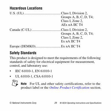
Hazardous LocationsU.S. (UL) ..........................................Class I, Division 2,
Groups A, B, C, D, T4;Class I, Zone 2,AEx nA IIC T4
Canada (C-UL) .................................Class I, Division 2, Groups A, B, C, D, T4;Class I, Zone 2, Ex nA IIC T4
Europe (DEMKO).............................Ex nA IIC T4
Safety StandardsThis product is designed to meet the requirements of the following standards of safety for electrical equipment for measurement, control, and laboratory use:
• IEC 61010-1, EN 61010-1
• UL 61010-1, CSA 61010-1
Note For UL and other safety certifications, refer to the product label or the Online Product Certification section.

NI 9234 Operating Instructions and Specifications 30 ni.com
Electromagnetic CompatibilityThis product meets the requirements of the following EMC standards for electrical equipment for measurement, control,and laboratory use:
• EN 61326 (IEC 61326): Class A emissions; Basic immunity
• EN 55011 (CISPR 11): Group 1, Class A emissions
• AS/NZS CISPR 11: Group 1, Class A emissions
• FCC 47 CFR Part 15B: Class A emissions
• ICES-001: Class A emissions
Note For the standards applied to assess the EMC of this product, refer to the Online Product Certification section.
Note For EMC compliance, operate this device with shielded cabling.

© National Instruments Corp. 31 NI 9234 Operating Instructions and Specifications
CE ComplianceThis product meets the essential requirements of applicable European Directives as follows:
• 2006/95/EC; Low-Voltage Directive (safety)
• 2004/108/EC; Electromagnetic Compatibility Directive (EMC)
Online Product CertificationRefer to the product Declaration of Conformity (DoC) for additional regulatory compliance information. To obtain product certifications and the DoC for this product, visit ni.com/certification, search by module number or product line, and click the appropriate link in the Certification column.
NI 9234 Operating Instructions and Specifications 32 ni.com
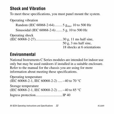
Shock and VibrationTo meet these specifications, you must panel mount the system.
Operating vibrationRandom (IEC 60068-2-64)......... 5 grms, 10 to 500 Hz
Sinusoidal (IEC 60068-2-6) ....... 5 g, 10 to 500 Hz
Operating shock(IEC 60068-2-27).............................. 30 g, 11 ms half sine,
50 g, 3 ms half sine,18 shocks at 6 orientations
EnvironmentalNational Instruments C Series modules are intended for indoor use only but may be used outdoors if installed in a suitable enclosure. Refer to the manual for the chassis you are using for more information about meeting these specifications.
Operating temperature(IEC 60068-2-1, IEC 60068-2-2) ..... –40 to 70 °C
Storage temperature(IEC 60068-2-1, IEC 60068-2-2) ..... –40 to 85 °C
Ingress protection.............................. IP 40

© National Instruments Corp. 33 NI 9234 Operating Instructions and Specifications
Operating humidity(IEC 60068-2-56).............................. 10 to 90% RH,
noncondensing
Storage humidity(IEC 60068-2-56).............................. 5 to 95% RH,
noncondensing
Maximum altitude............................. 2,000 m
Pollution Degree (IEC 60664) .......... 2
Environmental ManagementNI is committed to designing and manufacturing products in an environmentally responsible manner. NI recognizes that eliminating certain hazardous substances from our products is beneficial to the environment and to NI customers.
For additional environmental information, refer to the NI and the Environment Web page at ni.com/environment. This page contains the environmental regulations and directives with which NI complies, as well as other environmental information not included in this document.
NI 9234 Operating Instructions and Specifications 34 ni.com
Waste Electrical and Electronic Equipment (WEEE)EU Customers At the end of their life cycle, all products must be sent to a WEEE recycling center. For more information about WEEE recycling centers and National Instruments WEEE initiatives, visit ni.com/environment/weee.htm.
CalibrationYou can obtain the calibration certificate and information about calibration services for the NI 9234 at ni.com/calibration.
Calibration interval ........................... 1 year
RoHSNational Instruments
(RoHS)National Instruments RoHSni.com/environment/rohs_china (For information about China RoHS compliance, go to ni.com/environment/rohs_china.)

© National Instruments Corp. 35 NI 9234 Operating Instructions and Specifications
Where to Go for SupportThe National Instruments Web site is your complete resource for technical support. At ni.com/support you have access to everything from troubleshooting and application development self-help resources to email and phone assistance from NI Application Engineers.
National Instruments corporate headquarters is located at 11500 North Mopac Expressway, Austin, Texas, 78759-3504. National Instruments also has offices located around the world to help address your support needs. For telephone support in the United States, create your service request at ni.com/support and follow the calling instructions or dial 512 795 8248. For telephone support outside the United States, contact your local branch office:
Australia 1800 300 800, Austria 43 662 457990-0, Belgium 32 (0) 2 757 0020, Brazil 55 11 3262 3599, Canada 800 433 3488, China 86 21 5050 9800, Czech Republic 420 224 235 774, Denmark 45 45 76 26 00, Finland 358 (0) 9 725 72511, France 01 57 66 24 24, Germany 49 89 7413130, India 91 80 41190000, Israel 972 3 6393737, Italy 39 02 41309277, Japan 0120-527196,

National Instruments, NI, ni.com, and LabVIEW are trademarks of National Instruments Corporation. Refer to the Terms of Use section on ni.com/legal for more information about National Instruments trademarks. Other product and company names mentioned herein are trademarks or trade names of their respective companies. For patents covering National Instruments products/technology, refer to the appropriate location: Help»Patents in your software, the patents.txt file on your media, or the National Instruments Patent Notice at ni.com/patents.
© 2008 National Instruments Corp. All rights reserved.
374238C-01 Aug08
Korea 82 02 3451 3400, Lebanon 961 (0) 1 33 28 28, Malaysia 1800 887710, Mexico 01 800 010 0793, Netherlands 31 (0) 348 433 466, New Zealand 0800 553 322, Norway 47 (0) 66 90 76 60, Poland 48 22 3390150, Portugal 351 210 311 210, Russia 7 495 783 6851, Singapore 1800 226 5886, Slovenia 386 3 425 42 00, South Africa 27 0 11 805 8197, Spain 34 91 640 0085, Sweden 46 (0) 8 587 895 00, Switzerland 41 56 2005151, Taiwan 886 02 2377 2222, Thailand 662 278 6777, Turkey 90 212 279 3031, United Kingdom 44 (0) 1635 523545