ni 0.33 mn 0.33 co 0.33 fe 2 o 4 nanoparticles anchored on oxidized carbon nanotubes as advanced...
TRANSCRIPT
RSC Advances
PAPER
Publ
ishe
d on
23
July
201
4. D
ownl
oade
d by
Uni
vers
ity o
f B
irm
ingh
am o
n 26
/08/
2014
05:
57:2
5.
View Article OnlineView Journal | View Issue
Ni0.33Mn0.33Co0.3
aState Key Laboratory of Multiphase C
Engineering, Chinese Academy of Sciences,
ipe.ac.cn; [email protected]; [email protected]
82544850bInstitute of Chemical Engineering and Scien
Singapore 627833
† Electronic supplementary informa10.1039/c4ra04483e
Cite this: RSC Adv., 2014, 4, 33769
Received 21st May 2014Accepted 23rd July 2014
DOI: 10.1039/c4ra04483e
www.rsc.org/advances
This journal is © The Royal Society of C
3Fe2O4 nanoparticles anchored onoxidized carbon nanotubes as advanced anodematerials in Li-ion batteries†
Zailei Zhang,*a Guangwei Kan,a Wenfeng Ren,a Qiangqiang Tan,*a Ziyi Zhongb
and Fabing Su*a
We report a solvothermal synthesis of Ni0.33Mn0.33Co0.33Fe2O4 (NMCFO) nanoparticles anchored on the
surface of oxidized carbon nanotubes (OCNT) to form NMCFO/OCNT nanocomposites as advanced
anode materials in Li-ion batteries. Ni(CH3COO)2, Mn(CH3COO)2, Co(CH3COO)2, and FeCl3 were
employed as the metal precursors and CH3COONa, HOCH2CH2OH and H2O as the mixed solvent in the
synthesis. The obtained samples were characterized by X-ray diffraction, thermogravimetric analysis,
inductively coupled plasma optical emission spectrometry, X-ray photoelectron spectroscopy,
transmission electron microscopy, and scanning electron microscopy. It is found that the OCNT
provided functional groups on the outer walls to nucleate and anchor NMCFO nanoparticles (5–20 nm),
while retaining the inner walls intact with high conductivity. Compared with the bare NMCFO
nanoparticles, NMCFO/OCNT composites showed a significantly improved electrochemical performance
because OCNT can substantially inhibit the aggregation of NMCFO nanoparticles and buffer the volume
change, and moreover, the inner walls of OCNT provide excellent electronic conduction pathways. This
work opens an effective way for the fabrication of ferrite-based metal oxide/OCNT hybrids as promising
anode materials for Li-ion batteries.
1. Introduction
To achieve higher specic capacities than that of the conven-tional graphite (372 mA h g�1), in recent years nanosized metaloxides such as NiO,1 Fe2O3,2 Co3O4,3,4 ZnMn2O4,5 CoMn2O4,6
and MnFe2O4,7 have been intensively studied as anode mate-rials in Li-ion batteries (LIBs). However, severe aggregation ofthe particles and volume change of the electrode materialsduring discharge–charge processes oen lead to poor cyclingstability, sluggish kinetics in charge transfer and ionic diffu-sion, as well as high intrinsic resistance.8–11 These shortcomingscan induce additional performance degradation of the metaloxide based electrodes, especially at high current densities,seriously limiting their practical application.12 To circumventthe above technical barriers, conductive carbon materials areoen incorporated with metal oxides to form metal oxides/carbon composites, such as Fe2O3@carbon,13 Fe3O4
omplex Systems, Institute of Process
Beijing, China 100190. E-mail: zhangzl@
; Fax: +86-10-82544851; Tel: +86-10-
ces, A*star, 1 Pesek Road, Jurong Island,
tion (ESI) available. See DOI:
hemistry 2014
nanoparticles embedded in porous carbon,14 Co3O4 coated oncarbon nanotube,15 mesoporous carbon-encapsulated NiO,16
CoO coated on graphene,17 carbon nanobers@CoMn2O4
coaxial nanocables,18 and mesoporous Mn0.5Co0.5Fe2O4 nano-spheres grown on grapheme,19 which have partially improvedthe cycling stability and rate capability.20,21 These nano-structuredmetal-oxide-containing electrodes with small size areable to partially buffer the stress and strain effects caused by theparticle volume expansion/contraction during the Li-ion inser-tion/extraction, thus improving the cycling and rate capability.22
Meanwhile, the instructive guidelines for designing high-performance nanostructured hybrid materials based on metaloxides and carbon for LIBs have been established via theseresearch activities.23
Iron-based oxides have recently received increased attentionas very promising anode materials for rechargeable LIBsbecause of their high theoretical capacity, non-toxicity, low cost,and improved safety.24 Meanwhile, nanostructured carbonnanotubes (CNT) are also promising anode materials for LIBsdue to their large electrode/electrolyte contact area and activesurface, high chemical stability and conductivity, and goodmechanical strength.25–31 Therefore, in the past decade effortswere made to synthesize CNT–metal oxides nanoparticlehybrids or composites.32,33 The binding between CNT and metaloxides nanoparticles are quite diverse, e.g., by noncovalentinteractions (such as p–p stacking and hydrophobic wrapping),
RSC Adv., 2014, 4, 33769–33775 | 33769
RSC Advances Paper
Publ
ishe
d on
23
July
201
4. D
ownl
oade
d by
Uni
vers
ity o
f B
irm
ingh
am o
n 26
/08/
2014
05:
57:2
5.
View Article Online
electrostatic interactions, or by covalent bonding throughfunctionalization of outer wall by oxidation.34–36 Xu et al.prepared NiO/CNT composites as anode material using nitricacid treated CNT, which maintained the capacity at �800 mA hg�1 aer 50 discharge–charge cycles at a current density of 50mA g�1.37 Zhuo et al. prepared Co3O4/CNT composites usingoxidative treatment on CNT, which le a large number of acidicgroups on the surface, showing 776 mA h g�1 at the 100th cycleat a current density of 200 mA g�1.15 In addition, Wang et al.found that the carbon coated a-Fe2O3 hollow nanohorns sup-ported on nitric acid treated CNT backbones exhibited a verystable capacity retention of 800 mA h g�1 over 100 cycles at acurrent density of 500 mA g�1.12 From these literature results, itis found that metal oxides/CNT hybrids, in which the CNT arepre-oxidized partially, exhibit good electrochemical perfor-mance by virtue of their advantageous structural features.However, so far there has no report showing attractive hybridcontaining multicomponent ferrite-based metal oxides nano-particles and CNT for lithium storage.
Herein, we report a novel synthesis of Ni0.33Mn0.33Co0.33-Fe2O4 (NMCFO)/oxidized carbon nanotubes (OCNT) compositesby directly growing NMCFO nanoparticles on OCNT. In thisstrategy, NMCFO nanoparticles are uniformly dispersed on thesurface of OCNT to form NMCFO/OCNT network nano-composites. Compared with the bare NMCFO nanoparticles,NMCFO/OCNT exhibits signicantly improved electrochemicalperformance with excellent cycling stability and high rateperformance, suggesting a potential application as anodes infuture LIBs with a high energy density.
2. Experimental2.1 Material synthesis
2.1.1 Synthesis of oxidized carbon nanotubes (OCNT). Allthe chemicals were of analytical grade and purchased fromSinopharm Chemical Reagent Co., Ltd. The OCNTweremade bya modied Hummers method.38 Carbon nanotubes (CNT)(CNano Technology (Beijing) Ltd) were rst puried by calci-nation at 500 �C for 2 h and washed with diluted HCl (10%). Thepuried CNT (2 g) were put into a 250 mL round-bottom ask,followed with addition of 50 mL of concentrated sulfuric acid,and the mixture was stirred at room temperature overnight.Next, the ask was heated in an oil bath at 40 �C, and 0.5 g ofNaNO3 was added and dissolved in the suspension. This stepwas followed with a slow addition of 2.0 g of KMnO4, and thereaction temperature was maintained at 40 �C. The solution wasstirred for 30 min. Aerward, 100 mL of water was slowly addedto the ask. Aer 30 min, the ask was removed from the oilbath, followed with addition of 300 mL of water and 30 mL of30% H2O2 to terminate the reaction. Aer stirred at roomtemperature for 15 min, the sample was then repeatedlycentrifuged and washed with 10% HCl solution for severaltimes, rinsed with copious amounts of water. The nal precip-itate was dispersed in 20 mL of water and lyophilized. Finally, adry product of �1.9 g was collected.
2.1.2 Synthesis of Ni0.33Mn0.33Co0.33Fe2O4/oxidized carbonnanotubes (NMCFO/OCNT). All the chemicals were of analytical
33770 | RSC Adv., 2014, 4, 33769–33775
grade and purchased from Sinopharm Chemical Reagent Co.,Ltd. In a typical synthesis, Ni(CH3COO)2$4H2O (0.33 mmol),Mn(CH3COO)2$4H2O (0.33 mmol), Co(CH3COO)2$4H2O (0.33mmol), FeCl3$6H2O (2.0 mmol), CH3COONa$3H2O (10.0 mmol)and OCNT (x g) were dissolved/dispersed in distilled water (40mL) and HOCH2CH2OH (40 mL) to form a homogeneous slurry,which was then reuxed for 2 h at 110 �C under constant stir-ring in a three-neck ask. Subsequently, the mixture was sealedin a stainless-steel autoclave and heated at 200 �C for 48 h. Theresulting precipitates were collected by centrifugation, washedwith distilled water and absolute ethanol, and nally dried invacuum at 120 �C for 24 h. The obtained NMCFO/OCNT nano-composites containing OCNT (x g) 0.20, 0.15, 0.10, and 0.05 g ofOCNT were denoted NMCFO/OCNT-1, NMCFO/OCNT-2,NMCFO/OCNT-3, and NMCFO/OCNT-4, respectively. Similarly,bare NMCFO was prepared without adding OCNT, and NMCFO/CNT prepared by adding un-oxidized 0.10 g CNT. In addition,amorphous NMCFO/OCNT precursor was prepared as acomparison as follows: Ni(CH3COO)2$4H2O (0.33 mmol),Mn(CH3COO)2$4H2O (0.33 mmol), Co(CH3COO)2$4H2O (0.33mmol), FeCl3$6H2O (2.0 mmol), CH3COONa$3H2O (10.0 mmol)and OCNT (0.10 g) were dissolved/dispersed in distilled water(40 mL) and HOCH2CH2OH (40 mL) to form a homogeneousslurry, which was then reuxed for 2 h at 110 �C under constantstirring in a three-neck ask. The resulting precipitates werecollected by centrifugation, washed with distilled water andabsolute ethanol, and nally dried in vacuum at 120 �C for 24 hto obtain the amorphous NMCFO/OCNT precursors.
2.2 Materials characterization
X-ray diffraction patterns (XRD) were recorded on a PANanalytical X'Pert PRO MPD using the Cu Ka radiation of (l ¼1.5418 A). The microscopic feature of the samples was charac-terized by eld-emission scanning electron microscopy(FESEM) with an energy-dispersive X-ray spectrometer (EDX)(JSM-7001F, JEOL, Tokyo, Japan) and transmission electronmicroscopy (TEM) with an energy-dispersive X-ray spectrometer(EDX) (JEM-2010F, JEOL, Tokyo, Japan) operated at 300 V.Thermogravimetric (TG) analysis was carried out on an EXSTARTG/DTA 6300 (Seiko Instruments, Japan) at a heating rate of10 �C min�1 in air (200 mL min�1). The elemental analysis wasconducted by inductively coupled plasma optical emissionspectrometry (ICP-OES, Optima 5300DV, Pekin Elmer, US).X-ray photoelectron spectroscopy (XPS) analysis was carried outon an ESCALab250electron spectrometer from Thermo Scien-tic Corporation using monochromatic 150 W Al Ka radiation.Pass energy for then arrow scan was 30 eV. The chamber pres-sure was about 6.5 � 10�10 mbar. The binding energies werereferenced to the C1s line at 284.8 eV.
2.3 Electrochemical measurement
The working electrode was prepared by mixing the activematerials, acetylene black, and polyvinylidene uoride (PVDF)in a weight ratio of 80 : 10 : 10 with N-methylpyrrolidone (NMP)as a solvent. The resulting slurries were cast onto a common Cufoil (current collector). The lm composed of Cu foil and
This journal is © The Royal Society of Chemistry 2014
Paper RSC Advances
Publ
ishe
d on
23
July
201
4. D
ownl
oade
d by
Uni
vers
ity o
f B
irm
ingh
am o
n 26
/08/
2014
05:
57:2
5.
View Article Online
slurries were rolled into 25 mm thin sheets, and then dried at50 �C for 24 h. The lm were cut into disks with a diameter of 14mm, and then dried at 120 �C in vacuum for 24 h. CR2016 coin-type cells were assembled in an Ar-lled glove box with lithiumfoils as the counter electrodes and polypropylene microporouslms (Celgard 2400) as separators. The liquid electrolyte is 1mol L�1 LiPF6 in a mixture of ethylene carbonate (EC) anddimethyl carbonate (DMC) (1 : 1, v/v). The galvanostatic chargeand discharge tests were carried out on a NEWARE CT-3008-5V10mA testing instrument in a voltage range between 0.01 and3.0 V at current densities of 50, 100, 500, and 1000 mA g�1.Cyclic voltammetry (CV) was carried out using a CHI660Dpotentiostat in the voltage range of 0–3 V at a scanning rate of0.1 mV s�1 at room temperature. Electrochemical impedancespectroscopy (EIS) measurements were also conducted usingthe CHI660D potentiostat over a frequency range from 100 kHzto 10 mHz with an ac oscillation of 5 mV.
3. Results and discussion
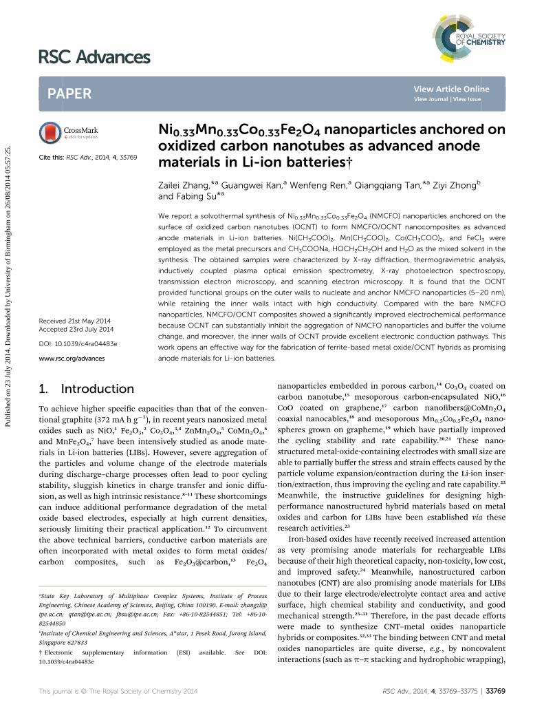
The carbon nanotubes (CNT) used in this work are about 12 nmin diameter and several micrometers in length.39 A modiedHummers method38 was used to prepare OCNT under mildoxidation. As determined by X-ray photoelectron spectroscopy(XPS), the OCNT contains �15 at% oxygen (Fig. S1†). Fig. 1ashows the XRD patterns of all the samples. The observation ofthe strong (002) peak at 2q values of about 26.3� in OCNTindicates its high graphite crystallinity (JCPDS no. 25-0284). Theobserved diffraction peaks at 2q values of 30.1, 35.6, 43.4, 53.7,57.3, and 62.8� correspond to the lattice planes of (220), (311),(400), (422), (511), and (440) respectively, indicating theformation of crystal Ni0.33Mn0.33Co0.33Fe2O4 (NMCFO) in thesamples of NMCFO, NMCFO/OCNT-1, NMCFO/OCNT-2,NMCFO/OCNT-3, and NMCFO/OCNT-4.40
Fig. 1b shows the TG curves of all the samples. The impurityof CNT is around 4.2 wt%, probably due to the presence of metalcatalyst (Fe/Co/Ni) residue aer the synthesis of CNT. However,these metal nanoparticles have been removed by calcinationfollowed with washing by dilute hydrochloric acid for OCNT. Itcan be seen that the weight loss derived from carbon combus-tion is located between 360 and 600 �C for OCNT, lower thanthat for CNT (400–650 �C), indicating the lowered combustiontemperature of OCNT aer the oxidation treatment. For thebare NMCFO nanoparticles, the weight loss of about 1.2 wt%may be derived from the trace amount of organic residue on
Fig. 1 XRD patterns (a) and TG curves (b) of all the samples.
This journal is © The Royal Society of Chemistry 2014
their surface. For NMCFO/OCNT composites, the weight lossstarts at about 230 �C, lowering than that of OCNT (360 �C). Thisis because the presence of metal oxides (NMCFO) can catalyti-cally promote the carbon combustion process at a lowertemperature.41 The measured weight loss of NMCFO/OCNT-1,NMCFO/OCNT-2, NMCFO/OCNT-3, and NMCFO/OCNT-4 isabout 41.7, 36.2, 28.9, and 16.7 wt% respectively in thetemperature range from 100 to 1000 �C, which can be ascribedto the decomposition of organic species and the combustion ofOCNT, suggesting that the weight percentage of OCNT isapproximately at 40.5, 35.0, 27.7, and 15.5 wt% in the samplesof NMCFO/OCNT-1, NMCFO/OCNT-2, NMCFO/OCNT-3, andNMCFO/OCNT-4, respectively.
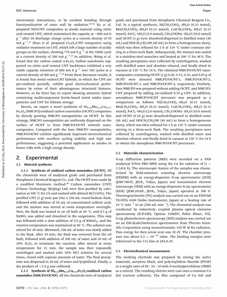
Fig. 2a shows the TEM image of NMCFO nanoparticles with asize range of 5–20 nm. Most of the NMCFO nanoparticles areagglomerated together due to the surface effect of nano-particles.42 Meanwhile, the HRTEM image of these nano-particles (Fig. 2b) reveals that the lattice fringe spacing is about0.293 nm, corresponding to the interplanar distance of (220)planes in NMCFO,40 and each nanoparticle is actually a singlecrystal. The EDX spectrum of NMCFO nanoparticles in Fig. 2cdemonstrates the presence of Ni, Mn, Co, Fe, and O elements.The elemental mapping images based on the NMCFO nano-particles show the homogeneous distribution of all the veelements (Ni, Mn, Co, Fe, and O) (Fig. S2†). The atomic ratio ofNi, Mn, Co, and Fe elements is approximate 1 : 1 : 1 : 6 fromICP-OES analysis. In fact, it is possible to tune the atomic ratioof NixMnyCozFe2O4 (x + y + z¼ 1, 0 < x, y, z < 1) by controlling theratio of raw materials (Ni(CH3COO)2, Mn(CH3COO)2, andCo(CH3COO)2). For example, for Ni0.2Mn0.4Co0.4Fe2O4, the usedraw materials amount is 0.2 mmol Ni(CH3COO)2, 0.4 mmolMn(CH3COO)2, and 0.4 mmol Co(CH3COO)2 (Fig. S3a†); whilefor Ni0.4Mn0.4Co0.2Fe2O4, the corresponding amount is 0.4mmol Ni(CH3COO)2, 0.4 mmol Mn(CH3COO)2, and 0.2 mmolCo(CH3COO)2 (Fig. S3b†). The SEM image in Fig. 2d shows that
Fig. 2 TEM images (a and b), and EDX spectrum of NMCFO nano-particles (c), and SEM of amorphous NMCFO/OCNT precursors (d).
RSC Adv., 2014, 4, 33769–33775 | 33771
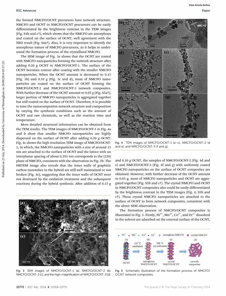
Fig. 4 TEM images of NMCFO/OCNT-1 (a–c), NMCFO/OCNT-2 (dand e), and NMCFO/OCNT-3 (f and g).
RSC Advances Paper
Publ
ishe
d on
23
July
201
4. D
ownl
oade
d by
Uni
vers
ity o
f B
irm
ingh
am o
n 26
/08/
2014
05:
57:2
5.
View Article Online
the formed NMCFO/OCNT precursors have network structure.NMCFO and OCNT in NMCFO/OCNT precursors can be easilydifferentiated by the brightness contrast in the TEM images(Fig. S4b and c†), which shows that the NMCFO are amorphousand coated on the surface of OCNT, well agreement with theXRD result (Fig. S4a†). Also, it is very important to identify theamorphous nature of NMCFO precursors, as it helps to under-stand the formation process of the crystallized NMCFO.
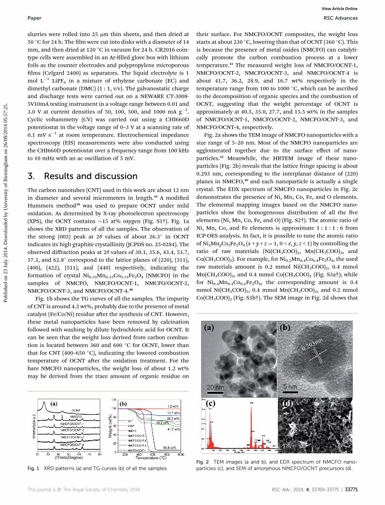
The SEM image of Fig. 3a shows that the OCNT are coatedwith NMCFO nanoparticles forming the network structure aeradding 0.20 g OCNT in NMCFO/OCNT-1. The surface of theOCNT becomes coarser aer coating with the smaller NMCFOnanoparticles. When the OCNT amount is decreased to 0.15(Fig. 3b) and 0.10 g (Fig. 3c and d), most of NMCFO nano-particles are coated on the surface of OCNT forming theNMCFO/OCNT-2 and NMCFO/OCNT-3 network composites.With further decrease of the OCNT amount to 0.05 g (Fig. S5a†),larger portion of NMCFO nanoparticles is aggregated togetherbut still coated on the surface of OCNT. Therefore, it is possibleto tune the nanocomposites network structure and compositionby varying the synthesis conditions such as the amount ofOCNT and raw chemicals, as well as the reaction time andtemperature.
More detailed structural information can be obtained fromthe TEM results. The TEM images of NMCFO/OCNT-1 in Fig. 4aand b show that smaller NMCFO nanoparticles are highlydispersed on the surface of OCNT aer adding 0.20 g OCNT.Fig. 4c shows the high resolution TEM image of NMCFO/OCNT-1, in which, the NMCFO nanoparticles with a size of around 15nm are attached to the surface of OCNT and the lattice with aninterplanar spacing of about 0.293 nm corresponds to the (220)plane of NMCFO, consistent with the observation in Fig. 2b. TheHRTEM image also reveals that the inner walls of graphiticcarbon nanotubes in the hybrid are still well maintained or notbroken (Fig. 4c), suggesting that the inner walls of OCNT werenot destroyed by the oxidation treatment and the subsequentreactions during the hybrid synthesis. Aer addition of 0.15 g
Fig. 3 SEM images of NMCFO/OCNT-1 (a), NMCFO/OCNT-2 (b),NMCFO/OCNT-3 (c), and the high-magnification of NMCFO/OCNT-3 (d).
33772 | RSC Adv., 2014, 4, 33769–33775
and 0.10 g OCNT, the samples of NMCFO/OCNT-2 (Fig. 4d ande) and NMCFO/OCNT-3 (Fig. 4f and g) with uniformly coatedNMCFO nanoparticles on the surface of OCNT composites areobtained. However, with further decrease of the OCNT amountto 0.05 g, most of NMCFO nanoparticles and OCNT are aggre-gated together (Fig. S5b and c†). The crystal NMCFO and OCNTin NMCFO/OCNT composites also could be easily differentiatedby the brightness contrast in the TEM images (Fig. 4, S5b andc†). These crystal NMCFO nanoparticles are attached to thesurface of OCNT to form network composites, consistent withthe above SEM observation.
The formation process of NMCFO/OCNT composites isillustrated in Fig. 5. Firstly, Ni2+, Mn2+, Co2+, and Fe3+ dissolvedin the solvent are adsorbed on the external surface of the OCNT,
Fig. 5 Schematic illustration of the formation process of NMCFO/OCNT network composites.
This journal is © The Royal Society of Chemistry 2014
Paper RSC Advances
Publ
ishe
d on
23
July
201
4. D
ownl
oade
d by
Uni
vers
ity o
f B
irm
ingh
am o
n 26
/08/
2014
05:
57:2
5.
View Article Online
because OCNT with functional groups on the outer walls is agood metal ion adsorbent (Fig. 5a).15,38 With the increase of thetemperature to 110 �C, these metal ions are accumulatedspecically on the outer wall by the oxidative functional groupson OCNT.35 These oxidative functional groups can act asheterogeneous nucleation sites in the early reaction stage tofacilitate the formation of small amorphous nanoparticlesduring the precipitation.43 Thereaer, the small amorphousNMCFO nanoparticles are generated and aggregated on thesurface of OCNT via the reaction (0.33Ni2+ + 0.33Mn2+ +0.33Co2+ + 2Fe3+ + 4H2O/ Ni0.33Mn0.33Co0.33Fe2O4 + 8H+) withthe water generated from the metal precursors (Fig. 5b). Withthe further increase of the temperature to 200 �C, the amor-phous NMCFO nanoparticles are crystallized to form crystalNMCFO nanoparticles (Fig. 5c), which are also coated on thesurface of the OCNT. And in the last stage, the crystal NMCFO/OCNT network composites are developed and formed (Fig. 5d).In case with addition of more OCNT, it will have more oxidativefunctional groups acting as the adsorption sites for the givenamounts of Ni2+, Mn2+, Co2+, and Fe3+. As a result, the formedNMCFO will become smaller in size and be dispersed moreuniformly on the OCNT surface as shown in Fig. 3, 4, and S5.†This is because of the dispersing effect of OCNT. In a controlexperiment, it was failed to get the uniform distribution ofNMCFO nanoparticles and CNT network composites by using0.10 g CNT without oxidization. Therefore, it is clear that theoxidative functional groups on the external surface of OCNT arethe nucleation centers and play the key role in the growth ofNMCFO nanoparticles.
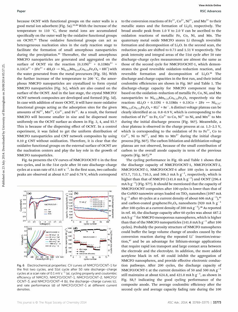
Fig. 6a presents the CV curves of NMCFO/OCNT-1 in the rsttwo cycles, and in the 51st cycle aer 50 rate discharge–chargecycles at a scan rate of 0.1 mV s�1. In the rst scan, two cathodicpeaks are observed at about 0.57 and 0.78 V, which correspond
Fig. 6 Electrochemical properties: CV curves of NMCFO/OCNT-1 forthe first two cycles, and 51st cycle after 50 rate discharge–chargecycles at a scan rate of 0.1 mV s�1 (a), cycling property and coulombicefficiency of NMCFO, NMCFO/OCNT-1, NMCFO/OCNT-2, NMCFO/OCNT-3, and NMCFO/OCNT-4 (b), the discharge–charge curves (c),and rate performance (d) of NMCFO/OCNT-1 at different currentdensities.
This journal is © The Royal Society of Chemistry 2014
to the conversion reactions of Fe3+, Co2+, Ni2+, and Mn2+ to theirmetallic states and the formation of Li2O, respectively. Thebroad anodic peak from 1.0 V to 2.0 V can be ascribed to theoxidation reactions of metallic Fe, Co, Ni, and Mn. Thequaternary metal oxide NMCFO stores Li through reversibleformation and decomposition of Li2O. In the second scan, thereduction peaks are shied to 0.73 and 1.51 V respectively. Thepeak intensity and integral areas of the 51st cycle aer 50 ratedischarge–charge cycles measurement are almost the same asthose of the second cycle for NMCFO/OCNT-1, which demon-strates the good reversible oxidation–reduction reaction, andreversible formation and decomposition of Li2O.44 Thedischarge and charge capacities in the rst run, and their initialcoulombic efficiencies are shown in Fig. S6† and Table 1. Thedischarge–charge capacity for NMCFO component may bebased on the oxidation–reduction of metallic Fe, Co, Ni, andMnnanoparticles to Ni0.33Mn0.33Co0.33Fe2O4 respectively via thereaction: 4Li2O + 0.33Ni + 0.33Mn + 0.33Co + 2Fe 4 Ni0.33-Mn0.33Co0.33Fe2O4 + 8Li
+ + 8e�. A distinct voltage plateau can beclearly identied at ca. 0.8–0.9 V, which is corresponding to thereduction of Fe3+ to Fe, Co2+ to Co, Ni2+ to Ni, and Mn2+ to Mnduring the initial discharge process (Fig. S6†). Meanwhile, aclear plateau is observed in the charge process at ca. 1.5–2.5 V,which is corresponding to the oxidation of Fe to Fe3+, Co toCo2+, Ni to Ni2+, and Mn to Mn2+ during the initial chargeprocess (Fig. S6†). The carbon lithiation and delithiation voltageplateau are not observed, because of the small contribution ofcarbon to the overall anode capacity in term of the previousreports (Fig. S6†).39
The cycling performance in Fig. 6b and Table 1 shows thatthe discharge capacity of NMCFO/OCNT-1, NMCFO/OCNT-2,NMCFO/OCNT-3, NMCFO/OCNT-4 aer 100 cycles is around673.7, 733.1, 710.3, and 506.3 mA h g�1, respectively, which ishigher than that of NMCFO (141.8 mA h g�1) and OCNT (296.4mA h g�1) (Fig. S7†). It should be mentioned that the capacity ofNMCFO/OCNT composites aer 100 cycles is lower than that ofthe CoNiO nanowire arrays loaded on TiO2 nanotubes (1097 mAh g�1 aer 40 cycles at a current density of about 606 mA g�1),45
and carbon-coated graphene/Fe3O4 nanosheets (920 mA h g�1
aer 100 cycles at a current density of 200 mA g�1).46 As reportedin ref. 40, the discharge capacity aer 60 cycles was about 487.2mA h g�1 for NMCFOmesoporous nanospheres, which is higherthan that of the NMCFO nanoparticles (141.8 mA h g�1 aer 100cycles). Probably the porosity structure of NMCFO nanospherescould buffer the large volume change of anodes caused by theconversion reaction during the repeated Li+ insertion/extrac-tion,47 and be an advantage for lithium-storage applicationsthat require rapid ion transport and large contact area betweenthe electrode and the electrolyte. In addition, the more addedacetylene black in ref. 40 could inhibit the aggregation ofNMCFO nanospheres, and provide effective electronic conduc-tion pathways. Aer 200 cycles, the discharge capacity ofNMCFO/OCNT-1 at the current densities of 50 and 500 mA g�1
still maintains at about 624.8, and 421.0 mA h g�1, as shown inFig. S8,† indicating the good cycling performance of thecomposite anode. The average coulombic efficiency aer thesecond cycle and average capacity fading rate during the 100
RSC Adv., 2014, 4, 33769–33775 | 33773
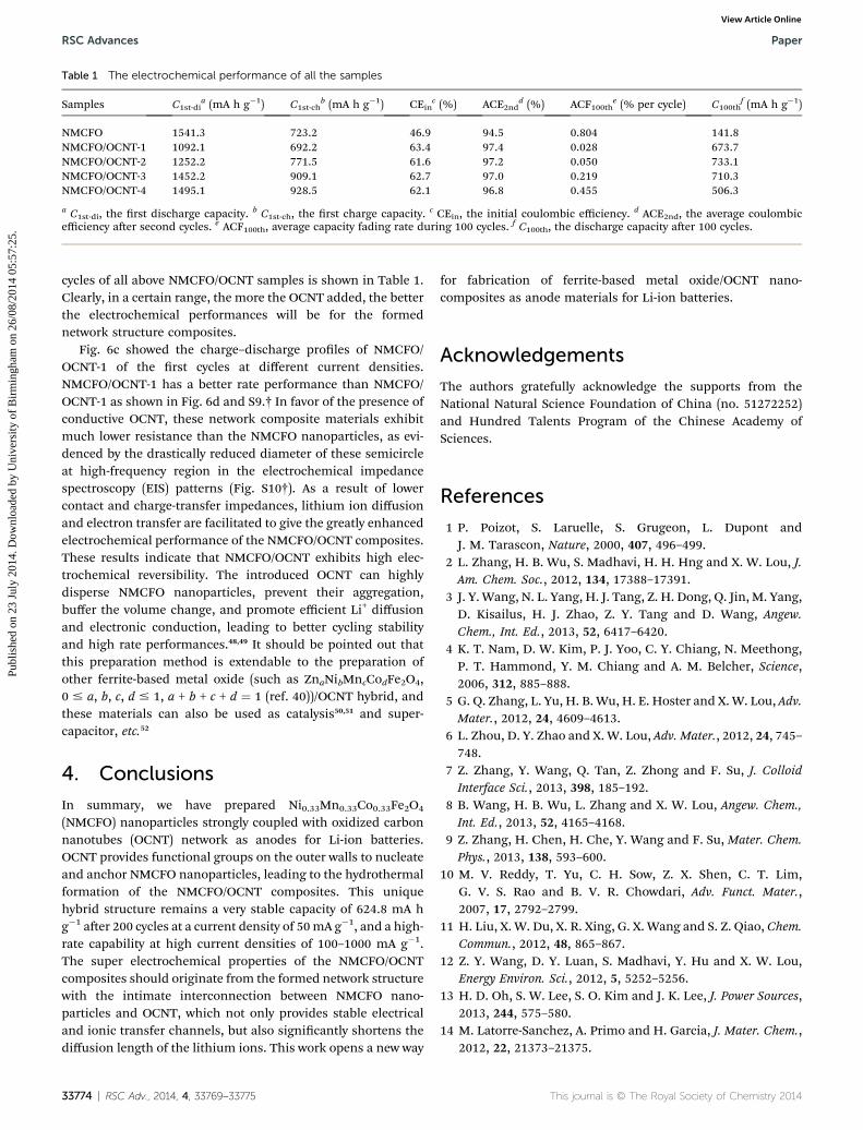
Table 1 The electrochemical performance of all the samples
Samples C1st-dia (mA h g�1) C1st-ch
b (mA h g�1) CEinc (%) ACE2nd
d (%) ACF100the (% per cycle) C100th
f (mA h g�1)
NMCFO 1541.3 723.2 46.9 94.5 0.804 141.8NMCFO/OCNT-1 1092.1 692.2 63.4 97.4 0.028 673.7NMCFO/OCNT-2 1252.2 771.5 61.6 97.2 0.050 733.1NMCFO/OCNT-3 1452.2 909.1 62.7 97.0 0.219 710.3NMCFO/OCNT-4 1495.1 928.5 62.1 96.8 0.455 506.3
a C1st-di, the rst discharge capacity. b C1st-ch, the rst charge capacity. c CEin, the initial coulombic efficiency. d ACE2nd, the average coulombicefficiency aer second cycles. e ACF100th, average capacity fading rate during 100 cycles. f C100th, the discharge capacity aer 100 cycles.
RSC Advances Paper
Publ
ishe
d on
23
July
201
4. D
ownl
oade
d by
Uni
vers
ity o
f B
irm
ingh
am o
n 26
/08/
2014
05:
57:2
5.
View Article Online
cycles of all above NMCFO/OCNT samples is shown in Table 1.Clearly, in a certain range, the more the OCNT added, the betterthe electrochemical performances will be for the formednetwork structure composites.
Fig. 6c showed the charge–discharge proles of NMCFO/OCNT-1 of the rst cycles at different current densities.NMCFO/OCNT-1 has a better rate performance than NMCFO/OCNT-1 as shown in Fig. 6d and S9.† In favor of the presence ofconductive OCNT, these network composite materials exhibitmuch lower resistance than the NMCFO nanoparticles, as evi-denced by the drastically reduced diameter of these semicircleat high-frequency region in the electrochemical impedancespectroscopy (EIS) patterns (Fig. S10†). As a result of lowercontact and charge-transfer impedances, lithium ion diffusionand electron transfer are facilitated to give the greatly enhancedelectrochemical performance of the NMCFO/OCNT composites.These results indicate that NMCFO/OCNT exhibits high elec-trochemical reversibility. The introduced OCNT can highlydisperse NMCFO nanoparticles, prevent their aggregation,buffer the volume change, and promote efficient Li+ diffusionand electronic conduction, leading to better cycling stabilityand high rate performances.48,49 It should be pointed out thatthis preparation method is extendable to the preparation ofother ferrite-based metal oxide (such as ZnaNibMncCodFe2O4,0 # a, b, c, d # 1, a + b + c + d ¼ 1 (ref. 40))/OCNT hybrid, andthese materials can also be used as catalysis50,51 and super-capacitor, etc.52
4. Conclusions
In summary, we have prepared Ni0.33Mn0.33Co0.33Fe2O4
(NMCFO) nanoparticles strongly coupled with oxidized carbonnanotubes (OCNT) network as anodes for Li-ion batteries.OCNT provides functional groups on the outer walls to nucleateand anchor NMCFO nanoparticles, leading to the hydrothermalformation of the NMCFO/OCNT composites. This uniquehybrid structure remains a very stable capacity of 624.8 mA hg�1 aer 200 cycles at a current density of 50mA g�1, and a high-rate capability at high current densities of 100–1000 mA g�1.The super electrochemical properties of the NMCFO/OCNTcomposites should originate from the formed network structurewith the intimate interconnection between NMCFO nano-particles and OCNT, which not only provides stable electricaland ionic transfer channels, but also signicantly shortens thediffusion length of the lithium ions. This work opens a new way
33774 | RSC Adv., 2014, 4, 33769–33775
for fabrication of ferrite-based metal oxide/OCNT nano-composites as anode materials for Li-ion batteries.
Acknowledgements
The authors gratefully acknowledge the supports from theNational Natural Science Foundation of China (no. 51272252)and Hundred Talents Program of the Chinese Academy ofSciences.
References
1 P. Poizot, S. Laruelle, S. Grugeon, L. Dupont andJ. M. Tarascon, Nature, 2000, 407, 496–499.
2 L. Zhang, H. B. Wu, S. Madhavi, H. H. Hng and X. W. Lou, J.Am. Chem. Soc., 2012, 134, 17388–17391.
3 J. Y. Wang, N. L. Yang, H. J. Tang, Z. H. Dong, Q. Jin, M. Yang,D. Kisailus, H. J. Zhao, Z. Y. Tang and D. Wang, Angew.Chem., Int. Ed., 2013, 52, 6417–6420.
4 K. T. Nam, D. W. Kim, P. J. Yoo, C. Y. Chiang, N. Meethong,P. T. Hammond, Y. M. Chiang and A. M. Belcher, Science,2006, 312, 885–888.
5 G. Q. Zhang, L. Yu, H. B. Wu, H. E. Hoster and X.W. Lou, Adv.Mater., 2012, 24, 4609–4613.
6 L. Zhou, D. Y. Zhao and X. W. Lou, Adv. Mater., 2012, 24, 745–748.
7 Z. Zhang, Y. Wang, Q. Tan, Z. Zhong and F. Su, J. ColloidInterface Sci., 2013, 398, 185–192.
8 B. Wang, H. B. Wu, L. Zhang and X. W. Lou, Angew. Chem.,Int. Ed., 2013, 52, 4165–4168.
9 Z. Zhang, H. Chen, H. Che, Y. Wang and F. Su, Mater. Chem.Phys., 2013, 138, 593–600.
10 M. V. Reddy, T. Yu, C. H. Sow, Z. X. Shen, C. T. Lim,G. V. S. Rao and B. V. R. Chowdari, Adv. Funct. Mater.,2007, 17, 2792–2799.
11 H. Liu, X. W. Du, X. R. Xing, G. X. Wang and S. Z. Qiao, Chem.Commun., 2012, 48, 865–867.
12 Z. Y. Wang, D. Y. Luan, S. Madhavi, Y. Hu and X. W. Lou,Energy Environ. Sci., 2012, 5, 5252–5256.
13 H. D. Oh, S. W. Lee, S. O. Kim and J. K. Lee, J. Power Sources,2013, 244, 575–580.
14 M. Latorre-Sanchez, A. Primo and H. Garcia, J. Mater. Chem.,2012, 22, 21373–21375.
This journal is © The Royal Society of Chemistry 2014
Paper RSC Advances
Publ
ishe
d on
23
July
201
4. D
ownl
oade
d by
Uni
vers
ity o
f B
irm
ingh
am o
n 26
/08/
2014
05:
57:2
5.
View Article Online
15 L. H. Zhuo, Y. Q. Wu, J. Ming, L. Y. Wang, Y. C. Yu,X. B. Zhang and F. Y. Zhao, J. Mater. Chem. A, 2013, 1,1141–1147.
16 M. Y. Cheng and B. J. Hwang, J. Power Sources, 2010, 195,4977–4983.
17 X. Huang, R. Wang, D. Xu, Z. Wang, H. Wang, J. Xu, Z. Wu,Q. Liu, Y. Zhang and X. Zhang, Adv. Funct. Mater., 2013, 23,4345–4353.
18 G. Zhang, H. Wu, H. Hoster and X. W. Lou, Energy Environ.Sci., 2014, 7, 302–305.
19 Z. Zhang, Y. Wang, D. Li, Q. Tan, Y. Chen, Z. Zhong andF. Su, Ind. Eng. Chem. Res., 2013, 52, 14906–14912.
20 H. X. Zhang, C. Feng, Y. C. Zhai, K. L. Jiang, Q. Q. Li andS. S. Fan, Adv. Mater., 2009, 21, 2299–2304.
21 A. L. M. Reddy, M. M. Shaijumon, S. R. Gowda andP. M. Ajayan, Nano Lett., 2009, 9, 1002–1006.
22 P. R. Bueno and E. R. Leite, J. Phys. Chem. B, 2003, 107, 8868–8877.
23 W. H. Shi, X. H. Rui, J. X. Zhu and Q. Y. Yan, J. Phys. Chem. C,2012, 116, 26685–26693.
24 L. Zhang, H. B. Wu and X. W. Lou, Adv. Energy Mater., 2013,4, 1300958.
25 S. L. Candelaria, Y. Y. Shao, W. Zhou, X. L. Li, J. Xiao,J. G. Zhang, Y. Wang, J. Liu, J. H. Li and G. Z. Cao, NanoEnergy, 2012, 1, 195–220.
26 J. M. Tarascon and M. Armand, Nature, 2001, 414, 359–367.27 S. W. Lee, N. Yabuuchi, B. M. Gallant, S. Chen, B. S. Kim,
P. T. Hammond and Y. Shao-Horn, Nat. Nanotechnol.,2010, 5, 531–537.
28 Z. Y. Cao and B. Q. Wei, Energy Environ. Sci., 2013, 6, 3183–3201.
29 Q. Zhang, J. Q. Huang, W. Z. Qian, Y. Y. Zhang and F. Wei,Small, 2013, 9, 1237–1265.
30 J. H. Kim, K. H. Lee, L. J. Overzet and G. S. Lee, Nano Lett.,2011, 11, 2611–2617.
31 H. Zhang, G. P. Cao, Z. Y. Wang, Y. S. Yang, Z. J. Shi andZ. N. Gu, Nano Lett., 2008, 8, 2664–2668.
32 H. Li, J. K. Jo, L. Zhang, C. S. Ha, H. Suh and I. Kim, Adv.Funct. Mater., 2010, 20, 3864–3873.
33 D. Eder, Chem. Rev., 2010, 110, 1348–1385.
This journal is © The Royal Society of Chemistry 2014
34 F. T. Edelmann, Angew. Chem., Int. Ed., 1999, 38, 1381–1387.35 J. Liu, A. G. Rinzler, H. J. Dai, J. H. Hafner, R. K. Bradley,
P. J. Boul, A. Lu, T. Iverson, K. Shelimov, C. B. Huffman,F. Rodriguez-Macias, Y. S. Shon, T. R. Lee, D. T. Colbertand R. E. Smalley, Science, 1998, 280, 1253–1256.
36 M. A. Correa-Duarte, J. Perez-Juste, A. Sanchez-Iglesias,M. Giersig and L. M. Liz-Marzan, Angew. Chem., Int. Ed.,2005, 44, 4375–4378.
37 C. H. Xu, J. Sun and L. A. Gao, J. Power Sources, 2011, 196,5138–5142.
38 Y. Y. Liang, H. L. Wang, P. Diao, W. Chang, G. S. Hong,Y. G. Li, M. Gong, L. M. Xie, J. G. Zhou, J. Wang,T. Z. Regier, F. Wei and H. J. Dai, J. Am. Chem. Soc., 2012,134, 15849–15857.
39 Z. Zhang, Y. Wang, M. Zhang, Q. Tan, X. Lv, Z. Zhong andF. Su, J. Mater. Chem. A, 2013, 1, 7444–7450.
40 Z. Zhang, Q. Tan, Y. Chen, J. Yang and F. Su, J. Mater. Chem.A, 2014, 2, 5041–5050.
41 E. C. Alyea and M. A. Keane, J. Catal., 1996, 164, 28–35.42 A. Demortiere, P. Panissod, B. P. Pichon, G. Pourroy,
D. Guillon, B. Donnio and S. Begin-Colin, Nanoscale, 2011,3, 225–232.
43 V. Georgakilas, D. Gournis, V. Tzitzios, L. Pasquato,D. M. Guldi and M. Prato, J. Mater. Chem., 2007, 17, 2679–2694.
44 C. Vidal-Abarca, P. Lavela and J. L. Tirado, Solid State Ionics,2010, 181, 616–622.
45 J. Y. Yao, P. Xiao, Y. H. Zhang, M. Zhan, F. Yang andX. Q. Meng, J. Alloys Compd., 2014, 583, 366–371.
46 Y. Z. Su, S. Li, D. Q. Wu, F. Zhang, H. W. Liang, P. F. Gao,C. Cheng and X. L. Feng, ACS Nano, 2012, 6, 8349–8356.
47 A. Latz and J. Zausch, J. Power Sources, 2011, 196, 3296–3302.48 X. H. Wang, X. W. Li, X. L. Sun, F. Li, Q. M. Liu, Q. Wang and
D. Y. He, J. Mater. Chem., 2011, 21, 3571–3573.49 L. Q. Tao, J. T. Zai, K. X. Wang, H. J. Zhang, M. Xu, J. Shen,
Y. Z. Su and X. F. Qian, J. Power Sources, 2012, 202, 230–235.50 P. Lee, H. Teng and C. Yeh, Nanoscale, 2013, 5, 7558–7563.51 S. Chen and S. Z. Qiao, ACS Nano, 2013, 7, 10190–10196.52 Z. Yu, L. Chen and S. Yu, J. Mater. Chem. A, 2014, 2, 10889–
10894.
RSC Adv., 2014, 4, 33769–33775 | 33775