nf usermanual
TRANSCRIPT

! "!
Nomad Factory Plug-Ins User Manual Version 2.0 Table of Contents INTRODUCTION 01 - User Manual / Table of Contents ................................................................................... 02 - End User License Agreement ........................................................................................ AUTHORIZATION 04 - Authorizing Online - Nomad Factory Internet Activation Tool.......................................... 06 - Authorizing Offline - Nomad Factory Manual Activation Tool………….…………............. WINDOWS VST INSTALL LOCATION 08 - Windows VST Plug-Ins Location ..................................................................................... PRESETS FORMAT 09 - Plug-In Presets Format ................................................................................................... MISCELLANEOUS 10 - Usage and Tips ...............................................................................................................
10 - System Requirements ..................................................................................................... 10 - Known Issues ..................................................................................................................
! #!
SOFTWARE PLUG-IN CONTROLS 11 - AMT - Amp Leveling ………………………………………………………………………… 12 - AMT - Max Warm ……………………………………………………………………………. 14 - AMT - Multi Max ……………………………………………………………………………… 16 - ASP - EQP-4 …………………………………………………………………………………. 21 - ASP - LM-662 ………………………………………………………………………………… 25 - ASP - SC-226 ………………………………………………………………………………… 31 - Blue Tubes BrickWall BW2S ……………………………………………………………….. 32 - Blue Tubes Compressor CP2S …………………………………………………………….. 33 - Blue Tubes Compressor FA770 ……………………………………………………………. 35 - Blue Tubes DeESSER DS2S ……………………………………………………………….. 36 - Blue Tubes Expander Gate GX622………………………………………………………… 37 - Blue Tubes Limiter LM2S …………………………………………………………………… 39 - Blue Tubes Dual-Analog Chorus CH2S……………………………………………………. 42 - Blue Tubes Vintage Oilcan Echo TLE-2S …………………………………………………. 43 - Blue Tubes Analog APH-2S ………………………………………………………………… 44 - Blue Tubes Stereo Imager ST-2S ………………………………………………………….. 45 - Blue Tubes Delay Model DL3D …………………………………………………………….. 47 - Blue Tubes Valve Driver ADR-2S ………………………………………………………….. 49 - Blue Tubes Equalizer BQ2S ………………………………………………………………... 50 - Blue Tubes Equalizer BX2S ………………………………………………………………… 52 - Blue Tubes Equalizer GEQ12 ………………………………………………………………. 53 - Blue Tubes Equalizer PEQ5B ………………………………………………………………. 55 - Blue Tubes Equalizer PEQ332 ……………………………………………………………... 57 - Blue Tubes Analog TrackBox ………………………………………………………………. 62 - BlueVerb DRV-2080………………………………………………………………………….. 64 - Essential Channel ……………………………………………………………………………. 68 - Essential Compressor ……………………………………………………………………….. 70 - Essential Gate/Expander ……………………………………………………………………. 72 - Essential Graphic EQ ………………………………………………………………………... 73 - Essential Loudness Maximizer ……………………………………………………………... 74 - Essential Multiband Compressor…………………………………………………………… 76 - Essential Multiband Loudness Maximizer ………………………………………………… 78 - Essential RetroVox …………………………………………………………………………. 82 - Liquid Compressor II ………………………………………………………………………… 84 - Liquid Delays II ………………………………………………………………………………. 87 - Liquid Gate II …………………………………………………………………………………. 89 - Liquid Mod II ………………………………………………………………………………….. 91 - Liquid Phase II ……………………………………………………………………………….. 93 - Liquid Verb II …………………………………………………………………………………. 95 - Retrology: Motown Bundle Introduction ...…………………………………………………. 96 - Retrology: Retro Film-Tone …………………………………………………………………. 97 - Retrology: Retro Music-Tone ……………………………………………………………….. 98 - Retrology: British MCL-2269 ……………………………………………………………….. 100 - Retrology: British NEQ-1972………………………………………………………………… 102 - Retrology: PulseTec EQs Introduction……………………………………………………… 103 - Retrology: PulseTec Mid-Range Equalizer MEQ-5………………………………………..
104 - Retrology: PulseTec Program Equalizer EQP-1A ………………………………………... 105 - Retrology: PulseTec Pre-Amplifier PRE-2S ….…………………………………………… 106 - Retrology: All-Tech 9063B EQ Introduction ………………………………………………
107 - Retrology: All-Tech 9063B EQ ……………………………………………………………… 108 - Rock Amp Legends ………………………………………………………………………….. 116 - Magnetic – Reel to Reel Audio Tape Warmer

! $!
TERMS OF USE AND END USER LICENSE AGREEMENT (“EULA”) FOR NOMAD FACTORY LLC SOFTWARE
Please read this document carefully, and accept the following End User License Agreement. By downloading, installing, and/or using Nomad Factory LLC Professional Audio Products, you agree to be bound by this Agreement. 1): DEFINITIONS This License Agreement ("Agreement") is a legal agreement between you (either an individual or a single entity) and Nomad Factory LLC ("Nomad Factory LLC.") for the Nomad Factory LLC product accompanying this Agreement, which includes computer software and may include associated media, printed materials, and "online" or electronic materials (collectively the "Software"). By exercising your rights to make and use copies of the Software, you agree to be bound by the terms of this Agreement. If you do not agree to the terms of this Agreement, you may not use the Software. The Software is protected by copyright laws and international copyright treaties, as well as other intellectual property laws and treaties. The Software is licensed, not sold. 2): LICENSE. You may install and use a copy of the SOFTWARE, or in its place, any prior version for the same operating system, on a single computer. The DEMO VERSION of the SOFTWARE is NOT LICENSED FOR COMMERCIAL USE. 3): COPYRIGHTS: All title and copyrights in and to the SOFTWARE (including but not limited to any images, photographs, animations, video, audio, music, text, and "applets" incorporated into the SOFTWARE), the accompanying printed materials are and shall remain the property of Nomad Factory LLC and Nomad Factory LLC owns any copies of the SOFTWARE. Copyright laws and international treaty provisions protect the SOFTWARE. Unauthorized reproduction or distribution of the SOFTWARE or documentation is subject to civil and criminal penalties. 4): RESTRICTIONS: You may not transfer, modify, rent, lease, loan, resell, distribute, network, electronically transmit or merge the SOFTWARE. You may not reverse engineer, decompile or disassemble the SOFTWARE, or otherwise attempt to discover the SOFTWARE source code. You are not permitted to copy the SOFTWARE or any of the accompanying documentation. 5): AUTHORIZATION CODE: The "Nomad Factory LLC. Products" only functions when you are in the possession of an authorization code. You will receive an authorization code upon completing the authorization code request procedure. Once your authorization code is activated, you may use the product. 6): DISCLAIMER OF WARRANTY: The SOFTWARE is provided "AS IS" and without warranty of any kind. The entire risk arising out of the use or performance of the SOFTWARE and documentation remains with user. To the maximum extent permitted by applicable law, Nomad Factory LLC. further disclaims all warranties, either express or implied, including, but not limited to, implied warranties of merchantability and fitness for a particular purpose, with regard to the SOFTWARE, and any accompanying hardware. To the maximum extent permitted by applicable law, in no event shall Nomad Factory LLC. be liable for any consequential, incidental, direct, indirect, special, punitive, or other damages whatsoever (including, without limitation, damages for loss of business profits, business interruption, loss of business information, or other pecuniary loss) arising out of this EULA or the use of or inability to use the SOFTWARE, even if Nomad Factory LLC. has been advised of the possibility of such damages. VIOLATION OF COPYRIGHT. If you violate the copyright of any third party or parties in the process of creating a copyrighted work, you agree that the copyright on your work is invalidated, forfeited, null and void. VIOLATION OF OTHER LICENSE. You may not violate the license agreement, in whole or in part, of this software or any software or software component required for using the Software. You agree to allow Nomad Factory LLC to verify compliance by any means. 7): GENERAL: This Agreement is the complete and exclusive statement of the mutual understanding of the parties and supersedes any other agreement relating to the Software. This Agreement shall be construed pursuant to the laws of the State of California and the United States without regard to the conflict of laws provisions thereof and without regard to the United Nations Convention on Contracts for the International Sale of Goods. To the extent that US law is applicable, the restriction on reverse engineering is limited to prohibit such activity to the maximum extent without violating the US Directive on the legal protection on computer programs. No waiver of any breach of any provision of this Agreement shall constitute a waiver of any prior, concurrent or subsequent breach of the same or any other provisions hereof, and no waiver shall be effective unless made in writing and signed by an authorized representative of Nomad Factory LLC. If any portion hereof is found to be void or unenforceable, the remaining provisions of this Agreement shall remain in full force and effect. Nomad Factory LLC 9164 Charleville Blvd, Suite #207 Beverly Hills CA 90212, USA

! %!
Nomad Factory Product Activation Thank you for purchasing Nomad Factory Software. After you install your software, please locate the folder named “Authorize Your Machine” which can be found on the install disc or downloaded installer file. Inside this folder you will find the following choices to authorize your software:
- NF Internet Activation: Use this if your computer is online. - NF Manual Activation: Use this if your computer is NOT online.
Authorizing Online: Nomad Factory Internet Activation Tool
In order to activate your software using the Nomad Factory Internet Activation Tool, your computer must be connected to the Internet.
If your computer is not connected to the Internet, please use the Manual activation tool.
Step 1:
After installing your software, you will notice a folder included called “Authorize Your Machine”. Open that folder and double-click on the application: “NF Internet Activation”
Step 2:
The following window will appear (see below). Once you have verified that your computer is connected to the Internet, then click “Activate Now” to continue. If you choose to Quit before activating, the product will run in DEMO mode.
! &!
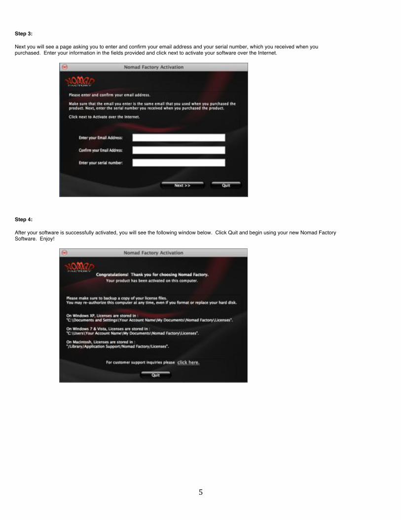
Step 3:
Next you will see a page asking you to enter and confirm your email address and your serial number, which you received when you purchased. Enter your information in the fields provided and click next to activate your software over the Internet.
Step 4:
After your software is successfully activated, you will see the following window below. Click Quit and begin using your new Nomad Factory Software. Enjoy!

! '!
Authorizing Offline: The Nomad Factory Manual Activation Tool
In order to activate your software using the Nomad Factory Manual Activation Tool, please follow these instructions:
Since your computer is not connected to the Internet, you will use the Manual Activation Tool to generate an authorization file and then copy it to another computer that has an Internet connection.
Step 1:
After installing your software, you will notice a folder included called “Authorize Your Machine”. Open that folder and double-click on the application: “NF Manual Activation”
Step 2:
The following window will appear (see below). Click “Activate New Product” to continue.
Step 3:
Enter and confirm your email address, then enter your serial number and click next.
This will generate a .html file on your desktop. Copy that .html file to a portable storage device (such as an external hard drive or USB flash drive) and then connect that drive to a computer that has Internet access. Once you are online, simply double-click on the .html file to launch your Internet browser and connect with NomadFactory.com. Follow the instructions to download your license file.

! (!
Step 4:
After downloading your license file, the authorization file (.auth) will appear on your desktop. Copy the downloaded file to a portable storage device and transfer it back over to the computer on which youʼve installed your Nomad Factory Software. Click on “Read License File” and select the file you have copied to authorize your computer.
Step 5:
After your software is successfully activated, you will see the following window below. Click Quit and begin using your new Nomad Factory Software. Enjoy!

! )!
WINDOWS VST INSTALL LOCATION
Where should I install the VST plug-ins on my Windows Computer?:
IMPORTANT: Per default the installer will install the VST plug-ins into: C:\Program Files\Steinberg\Vstplugins\ To change the install location, click the 'Change' button and select another location. (See picture below) The VST Plug-Ins can be installed to any location on your hard drive. However, every host or sequencer allows the user to set the VST Plug-Ins path in its preferences, so you have to make sure that you install the VST plug-in to the correct location defined in your host in order to use it.

! *!
PLUG-IN PRESETS FORMAT
The Nomad Factory plug-ins utilizes a Universal Exchange platform, this platform enables the user recall their saved presets in any of the supported hosts: AU, RTAS and VST. For this reason you will not use the standard presets protocol when working in the AU, RTAS and VST environments. Since the Nomad Factory Menu Bar is practically the same on all new Nomad Factory plug-ins. You will always know how to save presets of a Nomad Factory plug-in.
The Save Menu Button: Allows saving presets in the Nomad Factory Preset format to the disk for both Mac and PC platforms. - Save New Preset As : Allows you to type the preset name to be saved. - Save Current Preset : Current preset will be overwritten. Presets will be saved into: Macintosh OS X: Macintosh HD/Library/Application Support/Nomad Factory/Plug-in Settings/The Plug-in Name/00-User Presets Windows XP: C:\Documents and Settings\Your Account Name\My Documents\BBE Sound\Licenses Windows 7 & Vista: C:\Users\Your Account Name\My Documents\BBE Sound\Licenses
Loading Presets: Pressing the 'Factory Setting' menu will display the included factory presets.
The Utility Menu Button: - About 'the plug-in name' Will display information about the plug-in as well as the version number. - Others (menu items) If you are connected to the Internet, using this options will launch a browser and will navigate to the Nomad Factory website pages

! "+!
USAGE AND TIPS Several presets have been provided to get you started using Nomad Factory plug-ins, however, there is no “right” way to it. Simply adjust the settings to determine what sounds right to you. SYSTEM REQUIREMENTS Macintosh® AU, RTAS, VST - Universal Binaries - Macintosh G4, G5 and Intel Macs with Mac OS 10.4 / 10.5 / 10.6 or higher, 512 MB RAM, 1027 x 768 screen resolution, high quality audio interface with sample rates from 44 kHz to 192 kHz. Windows® RTAS, VST Intel Pentium III or Pentium IV system with Windows XP / Vista / Windows 7 (32 and 64 bit), 512 MB RAM, 1024 x 768 screen resolution, high quality audio interface with sample rates from 44 kHz to 192 kHz.
Sequencers and sound editors compatible with AU, RTAS, VST plug-ins, such as:
- Copyrights and trademarks are held by their respective holders: - Cubase SE/SL/SX - Nuendo - V-STack - Acid Pro - Logic Audio - Digital Performer - Pro Tools - Sonar - Sound Forge - Cool Edit Pro - Melodyne - Peak - Live - Pro Tools - Audio Hijack Pro - Rax - Kore - AU Lab - Final Cut Pro - Soundtrack Pro - WaveBurner - Garage Band - n-Track Studio - Adobe Audition - Tracktion - DSP-Quattro - Sagan Metro And any audio application that fully supports one of the above mentioned plug-in standards.
KNOWN ISSUES VST: (Windows) - Mouse Wheel control doesn't work. Pro Tools RTAS (Mac and Windows): - When loading a Pro Tools session, the presets menu will not display the saved name but instead 'Factory Setting'. The parameters and controls values are not affected and are loaded correctly. FOR SUPPORT AND ALL OTHER TECHNICAL QUESTIONS: Please use the following link: http://nomadfactory.com/support/index.htm Nomad Factory LLC 9164 Charleville Blvd, Suite #207 Beverly Hills CA 90212, USA

! ""!
ANALOG MASTERING TOOLS
AMT – AMP LEVELING The A.M.T Amp Leveling is a highly optimized look-ahead Brick-Wall Limiter and Level Maximization. The A.M.T Amp Leveler has been designed to be used for Mixing, Mastering, Tracking and Live use. Using a new proprietary algorithm ensuring a very smooth-warm sounding with maximum loudness and no digital-over-clipping as well as low CPU consumption for lightening-fast processing, the A.M.T Amp Leveler is nothing short of amazing.
This plug-in delivers look-ahead, brick-wall limiting to maximize the levels of any mixing or mastering project. Increase the Input Threshold to engage the limiter, and the levels are automatically increased. Recovery controls the release. Use the Out Ceiling to cap the maximum output at a safe level.
The controls and features of the A.M.T. Amp Leveling are described below: Input Threshold: -20 dB to +20 dB: Default: 0 dB Controls the Input and Threshold level (in dB) for the Amp Leveling, this is the level above which the maximizer begins to attenuate the signal; as the signal is attenuated by increasing the Input Threshold, the limiter automatically increases the level to make up for the attenuated level. Recovery (Release Time): 1 to 5: Default: 1 Controls how long it takes the limiter to return the output to the un-attenuated level. Out Ceiling: -20 dB to +20 dB: Default: 0 dB Sets the maximum output level after maximizing Power: On or Off: Default: On With the switch in the 'On' position, the equalizer is activated, and the red LED above the switch is illuminated.
NOTE: Clicking on the Nomad Factory logo will display the back panel or about panel.

! "#!
AMT – MAX WARM The A.M.T Max Warm is a highly optimized look-ahead Brickwall Limiter, Equalizer and Level Maximizer. What makes the A.M.T Max Warm process unique is the approach used for its dynamic signal analysis. Internally, the A.M.T Max Warm uses a special processing algorithm to accurately maximize the incoming signal level while limiting the ceiling peak levels. This approach tends to produce a more natural warm-sound, the A.M.T Max Warm also includes a two-band equalizer (Shelving/Peaking) with adjustable frequencies, making this plug-in an amazing advanced and versatile tool.
The controls and features of the A.M.T. Max Warm are described below: Input Threshold: -20 dB to +20 dB: Default: 0 dB Controls the Input and Threshold level (in dB) for the A.M.T. Max Warm, this is the level where the maximizer begins to attenuate the signal. As increasing the Input threshold attenuates the signal, the limiter automatically increases the level to make up for the attenuated level. Out Ceiling: -20 dB to +20 dB: Default: 0 dB Sets the maximum output level after maximizing
Limit Mode: 1 to 5: Default: 1 Sets the Limiting Character or Ratio for the limiter/maximizer, five settings are available. - 1: Minimum - 2: Gentle - 3: Medium - 4: Hard - 5: Pumping
Recovery (Release Time): 10 ms to 999 ms: Default: 100 ms Controls how long it takes the limiter to return the output to the un-attenuated level. Low Frequency: 60 Hz to 800 Hz: Default: 220 Hz This control determines the cut-off center frequency for the Low EQ filter. High Frequency: 1.2 kHz to 16 kHz: Default: 4.4 kHz This control determines the cut-off center frequency for the High EQ filter. Low Gain: ± 12 dB: Default: 0 dB

! "$!
The Low (frequency) Gain control is continuously variable with up to +12 dB of boost (full clockwise rotation) or -12 dB of cut (full counter-clockwise rotation). High Gain: ± 12 dB: Default: 0 dB The High (frequency) Gain control is continuously variable with up to +12 dB of boost (full clockwise rotation) or -12 dB of cut (full counter-clockwise rotation). Peaking Switch (Low): Shelving or Peaking: Default: Shelving This switch determines the type of filter equalization (Shelving or Peaking). With the switch in the 'On' position, the Low Peaking filter type is selected, and the switch is illuminated. Peaking Switch (High): Shelving or Peaking: Default: Shelving This switch determines the type of filter equalization (Shelving or Peaking). With the switch in the 'On' position, the High Peaking filter type is selected, and the switch is illuminated. EQ Switch (Low): On or Off: Default: On This switch enables or disables the Low Freq EQ of the A.M.T. Max Warm. With the switch in the 'On' position, the Max Warm Low Freq EQ is activated, and the switch is illuminated. EQ Switch (High): On or Off: Default: On This switch enables or disables the High Freq EQ of the A.M.T. Max Warm. With the switch in the 'On' position, the Max Warm High Freq EQ is activated, and the switch is illuminated. Power: On or Off: Default: On With the switch in the 'On' position, the Max Warm Limiter is activated, and the switch is illuminated.
NOTE: Clicking on the Max Warm logo label will display the back panel or about panel.

! "%!
AMT – MULTI MAX The A.M.T Multi Max multiband peak limiter is a highly optimized 3 band look-ahead Brickwall Limiter and Level Maximizer. The A.M.T Multi Max uses special processing algorithms to accurately spilt and maximize the incoming signal level while limiting the ceiling peak levels. This approach tends to produce a loud and clear natural, warm sound. The A.M.T Multi Max 3 band crossover with adjustable frequencies delivers sweet highs and punchy lows, making this plug-in an advanced and powerful tool. When you need maximum sound with minimum latency and complete control, the choice is clear, use the A.M.T Multi Max plug-in.
The controls and features of the A.M.T. Multi Max are described below: Input Threshold: -20 dB to +20 dB: Default: 0 dB Controls the Input and Threshold level (in dB) for the A.M.T. Max Warm, this is the level above which the maximizer begins to attenuate the signal; as the signal is attenuated by increasing the Input Threshold, the limiter automatically increases the level to make up for the attenuated level. Out Ceiling: -20 dB to +20 dB: Default: 0 dB Sets the maximum output level after maximizing Recovery (Release Time): 1 to 5: Default: 1 Controls how long it takes the limiter to return the output to the unattenuated level, five settings are available. - 1: Ultra-Fast - 2: Fast - 3: Medium - 4: Slow - 5: Ultra-Slow
Limit Mode: 1 to 5: Default: 1 Sets the Limiting Character or Ratio for the limiter/maximizer, five settings are available. - 1: Minimum - 2: Gentle - 3: Medium - 4: Hard - 5: Pumping

! "&!
X-Over Low: 60 Hz to 800 Hz: Default: 220 Hz This control determines the Low crossover frequency. X-Over High: 1.2 kHz to 7.2 kHz: Default: 2.9 kHz This control determines the High crossover frequency. Low Gain: ± 12 dB: Default: 0 dB Controls the threshold and make-up gain for the Low limiter section. The Low Gain control is continuously variable with up to +12 dB of boost (full clockwise rotation) or -12 dB of cut (full counter-clockwise rotation). Mid Gain: ± 12 dB: Default: 0 dB Controls the threshold and make-up gain for the Medium limiter section. The Mid Gain control is continuously variable with up to +12 dB of boost (full clockwise rotation) or -12 dB of cut (full counter-clockwise rotation). High Gain: ± 12 dB: Default: 0 dB Controls the threshold and make-up gain for the High limiter section. The High Gain control is continuously variable with up to +12 dB of boost (full clockwise rotation) or -12 dB of cut (full counter-clockwise rotation). Peaking Switch (Low): Smooth or Hard Peaking: Default: Smooth This switch determines the type of filter crossover (Smooth or Hard) used by the crossover. With the switch in the 'On' position, the Low Hard Peaking crossover type is selected, and the switch is illuminated. Peaking Switch (High): Smooth or Hard Peaking: Default: Smooth This switch determines the type of filter crossover (Smooth or Hard) used by the crossover. With the switch in the 'On' position, the High Hard Peaking crossover type is selected, and the switch is illuminated. Solo Switches (Low/Medium/High): On or Off: Default: Off This switches solos the corresponding frequency band of the A.M.T. Multi Max. Power: On or Off: Default: On With the switch in the 'On' position, the Max Warm Limiter is activated, and the switch is illuminated. NOTE: Clicking on the Max Warm logo label will display the back panel or about panel.
! "'!
ANALOG SIGNATURE PACK
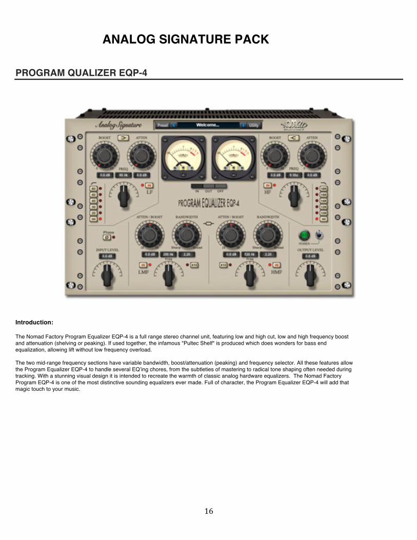
PROGRAM QUALIZER EQP-4
Introduction: The Nomad Factory Program Equalizer EQP-4 is a full range stereo channel unit, featuring low and high cut, low and high frequency boost and attenuation (shelving or peaking). If used together, the infamous "Pultec Shelf" is produced which does wonders for bass end equalization, allowing lift without low frequency overload. The two mid-range frequency sections have variable bandwidth, boost/attenuation (peaking) and frequency selector. All these features allow the Program Equalizer EQP-4 to handle several EQʼing chores, from the subtleties of mastering to radical tone shaping often needed during tracking. With a stunning visual design it is intended to recreate the warmth of classic analog hardware equalizers. The Nomad Factory Program EQP-4 is one of the most distinctive sounding equalizers ever made. Full of character, the Program Equalizer EQP-4 will add that magic touch to your music.

! "(!
EQP-4 CONTROLS
1- Low Frequency:
Shelf/Peaking Switch: This switch determines the type of filter equalization (shelving or peaking). Boost Knob: This control determines the amount of low shelving or peaking gain to be applied to the frequency set by the (CPS) Frequency switch. Atten Knob: This control determines the amount of low shelving or peaking attenuation to be applied to the frequency set by the (CPS) Frequency switch. Freq Selector: This control determines the frequency of the low portion of the EQP-4. 13 frequencies are available (CPS): 20, 30, 40, 50, 60, 70, 80, 90, 100, 120, 140, 160, 180 Hz LF IN Switch: This switch enables or disables the low portion of the EQP-4. HPF Selector: This control determines the frequency of the high pass filter, 5 frequencies are available: 20, 30, 40, 60, 80 Hz.

! ")!
2- High Frequency:
Shelf/Peaking Switch: This switch determines the type of filter equalization (shelving or peaking). Boost Knob: This control determines the amount of high shelving or peaking gain to be applied to the frequency set by the (KCS) Frequency switch. Atten Knob: This control determines the amount of high shelving or peaking attenuation to be applied to the frequency set by the (KCS) Frequency switch. Freq Selector: This control determines the frequency of the high portion of the EQP-4. 13 frequencies are available (KCS): 3, 3.6, 4, 4.6, 5, 5.6, 6, 7, 8, 10, 12, 14, 16 Khz HF IN Switch: This switch enables or disables the high portion of the EQP-4. LPF Selector: This control determines the frequency of the low pass filter, 5 frequencies are available: 10, 12, 14, 16, 18 Khz.

! "*!
3- Low Mid Freq / High Mid Freq controls:
Atten / Boost Knob: This control determines the amount of peaking gain or cut to be applied to the frequency set by the frequency switch. (+-18dB) Bandwidth Knob: This controls sets the proportion of frequencies surrounding the center frequency determined by the frequency switch to be affected by the boost/atten control. LMF - Low Mid Frequency: Freq Selector: This control determines the frequency of the low portion of the EQP-4. 13 frequencies are available: x1 - (CPS): 35, 40, 50, 75, 100, 150, 200, 250, 300, 350, 400, 450, 500 Hz x10 - (CPS/KCS): 350, 400, 500, 750 Hz, 1 Khz, 1.5, 2, 2.5, 3, 3.5, 4, 4.5, 5 Khz X10 Switch: This switch changes the frequencies of the Freq Selector control: x1 - (CPS): 35, 40, 50, 75, 100, 150, 200, 250, 300, 350, 400, 450, 500 Hz x10 - (CPS/KCS): 350, 400, 500, 750 Hz, 1 Khz, 1.5, 2, 2.5, 3, 3.5, 4, 4.5, 5 Khz LMF IN Switch: This switch enables or disables the low mid portion of the Program EQP-4. HMF - High Mid Frequency: Freq Selector: This control determines the frequency of the high portion of the EQP-4. 13 frequencies are available: x1 - (CPS): 200, 260, 320, 360, 420, 460, 520, 560, 620, 720, 760, 820, 960 Hz x10 - (KCS): 2, 2.6, 3.2, 3.6, 4.2, 4.6, 5.2, 5.6, 6.2, 7.2, 7.6, 8.2, 9.6 Khz X10 Switch: This switch changes the frequencies of the Freq Selector control: x1 - (CPS): 200, 260, 320, 360, 420, 460, 520, 560, 620, 720, 760, 820, 960 Hz x10 - (KCS): 2, 2.6, 3.2, 3.6, 4.2, 4.6, 5.2, 5.6, 6.2, 7.2, 7.6, 8.2, 9.6 Khz HMF IN Switch: This switch enables or disables the high mid portion of the Program EQP-4.

! #+!
Input Level: - This control determines the input level of the Program EQP-4. - 12 positions are available: 12, -10, -10, -8, -6, -4, -2, 0, +2, +4, +6, +8, +10, +12 dB.
Output Level: - This control determines the output level of the Program EQP-4. - 12 positions are available: 12, -10, -10, -8, -6, -4, -2, 0, +2, +4, +6, +8, +10, +12 dB
Phase: - This control inverts the phase of the Program EQP-4.
Power: - Turns On/Off the Program Equalizer EQP-4. (Bypass)
- VU-Meters:
Determines what is displayed on the VU meters. If OFF is selected, the meters will be turned off. If the meters select switch is set to IN or OUT, then the meters will reflect the input or output signal levels.
! #"!
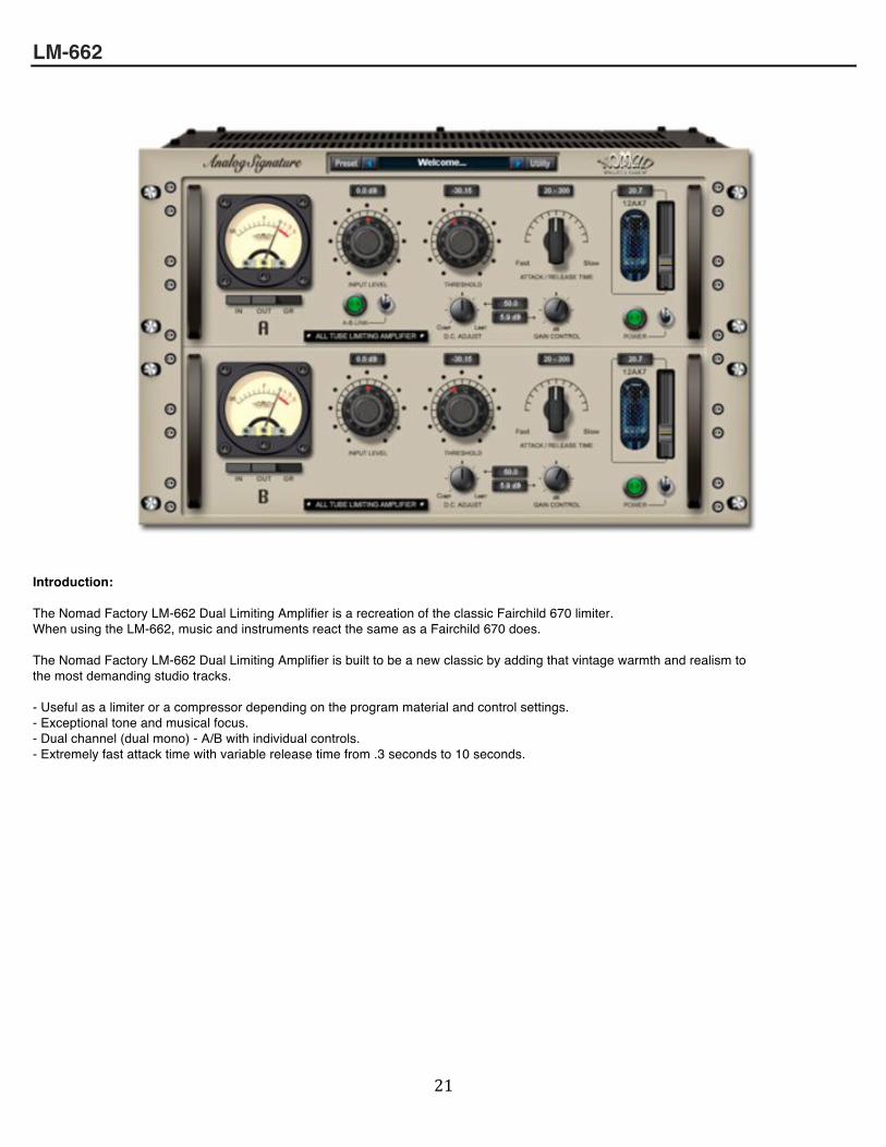
LM-662
Introduction: The Nomad Factory LM-662 Dual Limiting Amplifier is a recreation of the classic Fairchild 670 limiter. When using the LM-662, music and instruments react the same as a Fairchild 670 does. The Nomad Factory LM-662 Dual Limiting Amplifier is built to be a new classic by adding that vintage warmth and realism to the most demanding studio tracks. - Useful as a limiter or a compressor depending on the program material and control settings. - Exceptional tone and musical focus. - Dual channel (dual mono) - A/B with individual controls. - Extremely fast attack time with variable release time from .3 seconds to 10 seconds.
! ##!
LM-662 FEATURES
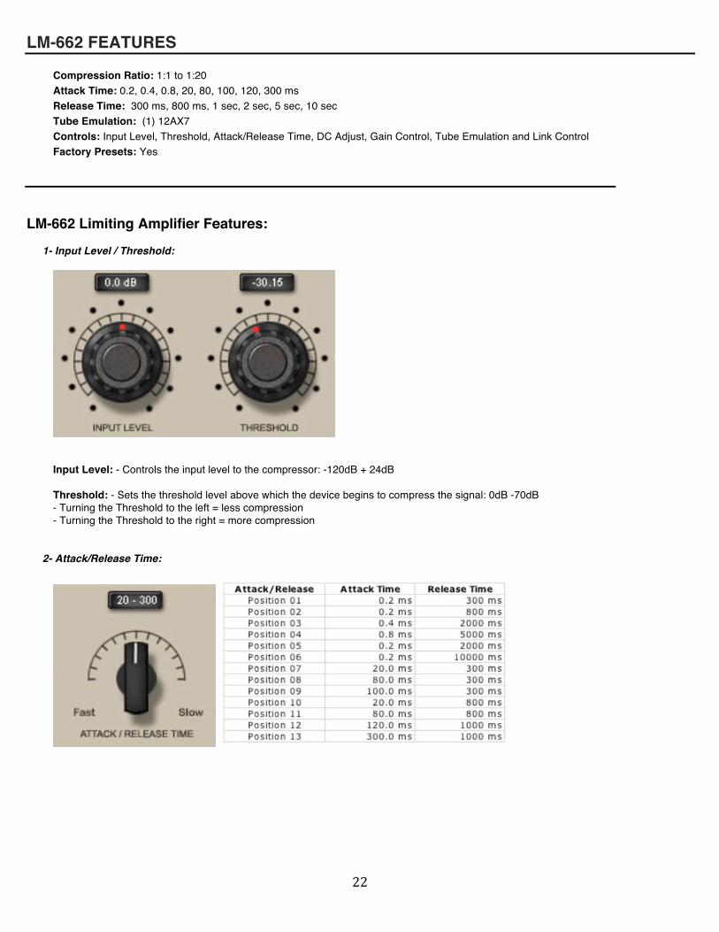
Compression Ratio: 1:1 to 1:20 Attack Time: 0.2, 0.4, 0.8, 20, 80, 100, 120, 300 ms Release Time: 300 ms, 800 ms, 1 sec, 2 sec, 5 sec, 10 sec Tube Emulation: (1) 12AX7 Controls: Input Level, Threshold, Attack/Release Time, DC Adjust, Gain Control, Tube Emulation and Link Control Factory Presets: Yes
LM-662 Limiting Amplifier Features:
1- Input Level / Threshold:
Input Level: - Controls the input level to the compressor: -120dB + 24dB Threshold: - Sets the threshold level above which the device begins to compress the signal: 0dB -70dB - Turning the Threshold to the left = less compression - Turning the Threshold to the right = more compression
2- Attack/Release Time:

! #$!
3- D.C. Adjust / Gain Control:
DC Adjust: On an original Fairchild, this was called DC Threshold and was on the rear of the unit (not accessible from front panel). We labeled that control DC Adjust to not confuse with the Threshold control. The DC Adjust lets you adjust the Knee/Ratio of the LM-662. You are able to control how the amplifier reacts to the audio signal coming in. By turning the DC Adjust to the left, the LM-662 acts more like a 'compressor', by turning the DC Adjust to the right, the LM-662 acts more like a 'limiter'. The best thing about the DC Adjust is you can find that magic spot in-between. Gain Control: Controls the LM-662 output level in dB: -60dB / +24dB
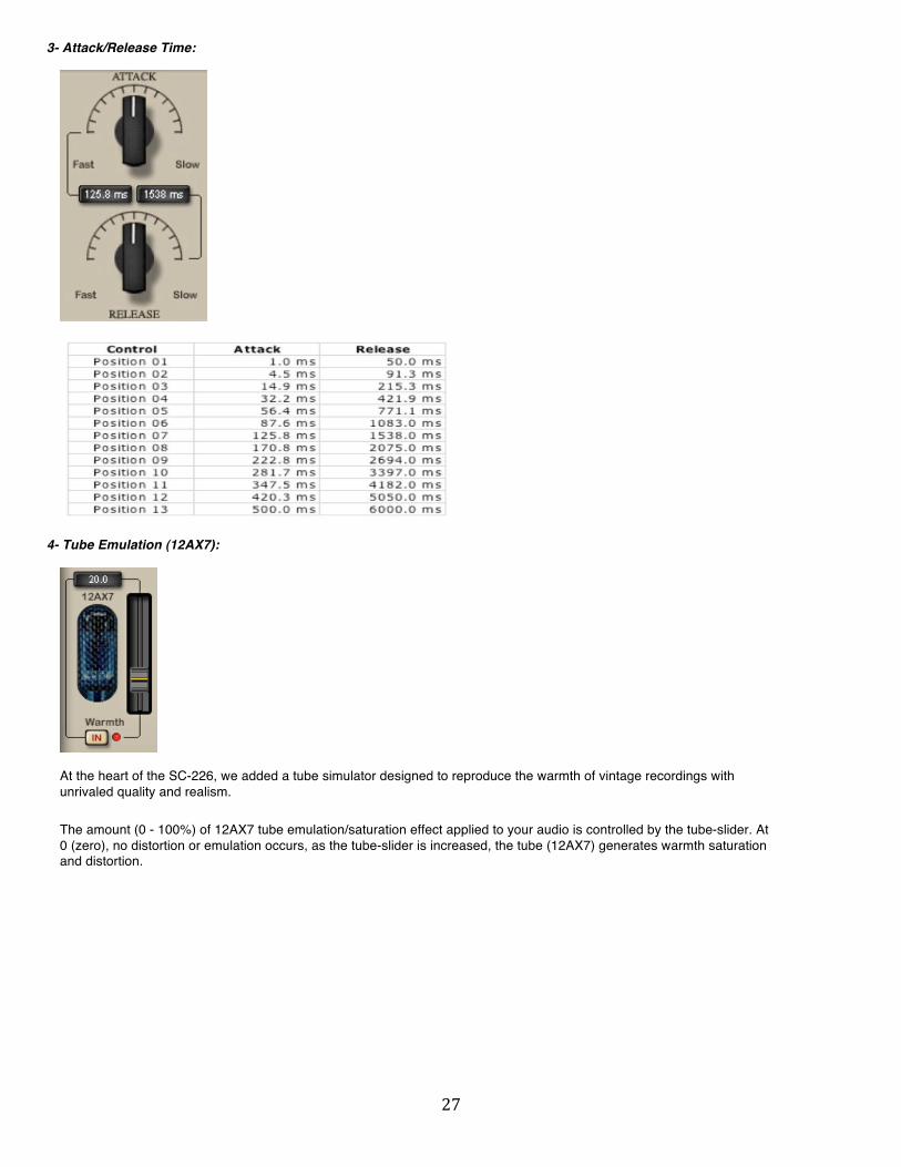
4- Tube Emulation (12AX7):
At the heart of the LM-662, we added a tube simulator designed to reproduce the warmth of vintage recordings with unrivaled quality and realism. The amount (0 - 100%) of 12AX7 tube emulation/saturation effect applied to your audio is controlled by the tube-slider. At 0 (zero), no distortion or emulation occurs, as the tube-slider is increased, the tube (12AX7) generates warmth saturation and distortion.
5- A/B Link Control:
This control allows the two sets of controls to be linked. If the controls are given an offset while unlinked, the offset between controls is NOT preserved when the controls are linked.

! #%!
6- VU-Meter:
Determines what is displayed on the VU meter. If GR is selected, the meter will show the gain reduction in dB, If the meter select switch is set to IN or OUT, then the meter will reflect the input or output signal level.

! #&!
SC-226
Introduction: The Nomad Factory Studio Channel SC-226 is a stereo channel recording plug-in, featuring 4-band equalizer, an analog "signature" optical compressor. Plus, at the heart of the shelving and bell filters, a tube simulator and Brick-Wall peak limiter designed to reproduce the warmth of vintage recordings with unrivaled quality and realism. The Studio Channel is tube style virtual equalizer / compressor. It is equally suited for delicate vocal as well as dynamic instrument recordings such as lead guitar, bass guitar, drums and horns. The algorithm was designed to emulate the response of a high-end vintage analog equalizer/compressor. Exceptional for tracking, mixing or mastering, the Studio Channel recreates the warm sound qualities of its analog hardware ancestors.
SC-226 FEATURES • Compression Ratio: 1:1 to 10:1 • Attack Time: 1, 4.47, 14.9, 32.2, 56.4, 87.6, 125.8, 170.8, 222.8, 281.7, 347.5, 420.3, 500 ms • Release Time: 50, 91.3, 215.3, 421.9, 711.1, 1083, 1538, 2075, 2694, 3397, 4182, 5050, 6000 ms • Tube Emulation: (1) 12AX7 • Bass Freq Select: 22, 33, 50, 70,100, 160, 230, 320, 420, 520, 620, 720, 820 Hz • Bass Freq Gain: (shelving or peaking) +-24dB • Low Mid Freq Select: 200, 300, 400, 500, 600, 700, 800, 900 Hz, 1 Khz, 1.5, 2, 2.5, 3 Khz • Low Mid Freq Gain: (peaking) +-16dB • High Mid Freq Select: 1.2, 1.6, 1.8, 2.2, 2.8, 3.2, 3.8, 4.2, 4.8, 5.2, 5.8, 6.2, 6.8 Khz • High Mid Freq Gain: (peaking) +-16dB • Treble Freq Select: 2, 3, 4, 5, 6, 7, 8, 9, 10, 12, 14, 16, 18 Khz • Treble Freq Gain: (shelving or peaking) +-20dB • High Pass Filter: Off, 20, 30 ,40 ,60, 80 Hz

! #'!
1- Input Level / Output Level:
Input Level: - This control determines the input level of the Studio Channel SC-226. (-120dB / +24dB)
Output Level: - This control determines the output level of the Studio Channel SC-226. (-120dB / +24dB)
2- Threshold / Compression:
Threshold: Sets the threshold level above which the device begins to compress the signal: 0dB -70dB - Turning the Threshold to the left = less compression - Turning the Threshold to the right = more compression Compression: (Ratio) The Compression control lets you adjust the Ratio of the compression. You are able to control how the amplifier reacts to the audio signal coming in. IN Switch: This switch enables or disables the compressor of the SC-226 PK Switch: This switch determines the level detection response between Peak and RMS modes. When enabled: Peak is selected. When disabled: RMS is selected.
! #(!
3- Attack/Release Time:
4- Tube Emulation (12AX7):
At the heart of the SC-226, we added a tube simulator designed to reproduce the warmth of vintage recordings with unrivaled quality and realism. The amount (0 - 100%) of 12AX7 tube emulation/saturation effect applied to your audio is controlled by the tube-slider. At 0 (zero), no distortion or emulation occurs, as the tube-slider is increased, the tube (12AX7) generates warmth saturation and distortion.

! #)!
5- Equalizer – Bass:
Shelf/Peaking Switch: This switch determines the type of filter equalization (shelving or peaking). Bass Knob: This control determines the amount of low shelving or peaking gain or cut to be applied to the frequency set by the Frequency switch. (+-20dB) Freq Selector: This control determines the frequency of the low portion of the equalizer. 13 frequencies are available: 22, 33, 50, 70,100, 160, 230, 320, 420, 520, 620, 720, 820 Hz IN Switch: This switch enables or disables the low portion of the equalizer.
6- Equalizer – Treble:
Shelf/Peaking Switch: This switch determines the type of filter equalization (shelving or peaking). Treble Knob: This control determines the amount of high shelving or peaking gain or cut to be applied to the frequency set by the Frequency switch. (+-20dB) Freq Selector: This control determines the frequency of the high portion of the equalizer. 13 frequencies are available: 2, 3, 4, 5, 6, 7, 8, 9, 10, 12, 14, 16, 18 Khz IN Switch: This switch enables or disables the high portion of the equalizer.

! #*!
7- Equalizer - Low Mid Freq controls.
Low Mid Gain Knob: This control determines the amount of peaking gain or cut to be applied to the frequency set by the Low Mid Frequency switch. (+-16dB) Low Mid Freq Selector: This control determines the frequency of the low mid portion of the equalizer. 13 frequencies are available: 200, 300, 400, 500, 600, 700, 800, 900 Hz, 1 Khz, 1.5, 2, 2.5, 3 Khz IN Switch: (Low Mid) This switch enables or disables the low mid portion of the equalizer. Q Switch: (Low Mid) This switch determines the Q or Slope of the Low Mid portion of the equalizer. Off = normal, On = Hi Q
8- Equalizer – High Mid Freq controls.
High Mid Gain Knob: This control determines the amount of peaking gain or cut to be applied to the frequency set by the High Mid Frequency switch. (+-16dB) High Mid Freq Selector: This control determines the frequency of the high mid portion of the equalizer. 13 frequencies are available: 1.2, 1.6, 1.8, 2.2, 2.8, 3.2, 3.8, 4.2, 4.8, 5.2, 5.8, 6.2, 6.8 Khz IN Switch: (High Mid) This switch enables or disables the high mid portion of the equalizer. Q Switch: (High Mid) This switch determines the Q or Slope of the High Mid portion of the equalizer. Off = normal, On = Hi Q
9- Equalizer - High Pass Filter:
HPF Selector: This control determines the frequency of the high pass filter, 5 frequencies are available: Off - 20, 30, 40, 60, 80 Hz

! $+!
10- Equalizer - EQ-CP, Limiter, Phase, Power:
EQ-CP: - This control determines: - OFF = compression applied before the EQ section. - ON = compression applied after the EQ section.
Limiter: - This control applies a BrickWall Limiter to the output of the Studio Channel SC-226.
Phase: - This control inverts the phase of the Studio Channel SC-226.
Power: - Turns On/Off the Studio Channel SC-226. (Bypass)
11- VU-Meter:
Determines what is displayed on the VU meter. If GR is selected, the meter will show the gain reduction in dB, If the meter select switch is set to IN or OUT, then the meter will reflect the input or output signal level.

! $"!
BLUE TUBES DYNAMICS PACK
BT BrickWall BW2S
The BT BrickWall BW2S is a simple and elegant brick wall compressor/limiter. Just insert the BT BrickWall BW2S on your mono or stereo track, and you have smooth audio without the unwanted transients. By using this compressor/limiter on your master track, harsh peaks will be eliminated, allowing you to increase the overall level of your mix.
Threshold: 0 to -30 dB: Default: 0 dB Sets the decibel (dB) threshold to the level at which the compressor begins to work. If you set it to -10 dB for instance, any signal exceeding the Threshold level (-10 dB) are reduced in level, and the amount of reduction is shown on the GR meter.
Release: 1 to 1000 ms; Default: 489.5 ms Controls how long (ms) it takes to release a signal from the compressor once it's dipped below your specified threshold. A long release time can be useful for adding sustain to a signal - On guitar solos for example. Peak Remover: On or Off: Default: On This switch engages the output 'Brick Wall' limiter. The 'Brick Wall' limiter or Peak Remover is set to 0 dB. Meters: IN, OUT or GR: Default: GR Determines the mode of the VU Meters. When set to GR, the VU Meters indicates the Gain Reduction level in dB. When set OUT, the VU Meters indicates the output level in dB. When set to IN, the VU Meters indicates the input level in dB. Bypass: On or Off: Default: Off When the Bypass control switch is “On”, the BT BrickWall BW2S-XP plug-in is disabled.

! $#!
BT Compressor CP2S
The BT Compressor CP2S emulates analog tube compressors in terms of looks, functions and sound. This variable-ratio compressor provides various compression choices, including RMS and Peak compressions. Easy to describe with words, but the warm analog sound of the BT Compressor CP2S is something you need to hear for yourself.
Threshold: 0 to -60 dB: Default: 0 dB Sets the decibel (dB) threshold to the level at which the compressor begins to work. If you set it to -10 dB for instance, any signal exceeding the Threshold level (-10 dB) are reduced in level, and the amount of reduction is shown on the GR meter. Ratio: 1:1 to Inf. dB: Default: 2.0:1 dB This sets the amount of compression, in dB, applied to a signal once it violates your pre-set threshold. A ratio of 4:1 will output 1 dB for every 4 dB of input signal that exceeds your targeted threshold Attack: 0.1 to 1000 ms: Default: 50 ms The time, measured in milliseconds (ms), it takes for the compressor to reach its maximum level on the sound. A fast attack can be useful for damping percussive peaks so the overall track level can be increased. Can also add punch to a track. Release: 50 to 5000 ms; Default: 200 ms Controls how long (ms) it takes to release a signal from the compressor once it's dipped below your specified threshold. A long release time can be useful for adding sustain to a signal - On guitar solos for example. RMS/Peak: RMS or Peak: Default: RMS Sets the level detector: RMS offers the closest approximation to the way in which our ears respond to sound, RMS provides a very natural-sounding dynamic control, where the Peak type of compressor will more accurately track the peak levels of the individual drum beats.
Make-Up: -20 to +20 dB: Default: 0 dB Sets the overall output level of the effect (dB). This control is useful to adjust the output level again after its been reduced from applying compression to a signal. Meter: IN, OUT or GR: Default: GR Determines the mode of the VU Meters. When set to GR, the VU Meters indicates the Gain Reduction level in dB. When set OUT, the VU Meters indicates the output level in dB. When set to IN, the VU Meters indicates the input level in dB. Bypass: On or Off: Default: Off When the Bypass control switch is “On”, the BT Compressor CP2S plug-in is disabled.

! $$!
BT Compressor FA770
The BT Compressor FA770 provides the operation and sound of highly coveted analog compressors. The FA770 is designed with a fixed-ratio and “time constant” switch (see settings below) as part of its characteristic vintage sound. This model proves that you do not need many knobs and sliders to achieve the great compression sound of the FA770. Adjust the Threshold, maybe the Time Constant to adjust the speed, and there you have it.
Input: 00 to 10: Default: 05 This control determines the input level of the BT Compressor FA770 Threshold: 0 to -60 dB: Default: 0 dB Sets the decibel (dB) threshold to the level at which the compressor begins to work. If you set it to -10 dB for instance, any signal exceeding the Threshold level (-10 dB) are reduced in level, and the amount of reduction is shown on the GR meter. MODE: A or B: Default: A This control determines the active set of Time Constant presets. A = 6 Attack/Release presets. B = 6 Attack/Release presets.
Time Constant (Attack/Release): Sets the Attack and Release of the FA770.
MODE A: Attack Release -------------------------------- - 1 -> 0.2 ms -> 300 ms - 2 -> 0.2 ms -> 800 ms - 3 -> 4.0 ms -> 2 Seconds - 4 -> 4.0 ms -> 5 Seconds - 5 -> 40 ms -> 600 ms - 6 -> 40 ms -> 300 ms
Time Constant (Attack/Release): Sets the Attack and Release of the FA770. MODE B: Attack Release --------------------------------! - 1 -> 20 ms -> 300 ms - 2 -> 20 ms -> 800 ms - 3 -> 40 ms -> 2 Seconds - 4 -> 40 ms -> 5 Seconds - 5 -> 120 ms -> 600 ms - 6 -> 120 ms -> 300 ms

! $%!
Make-Up Gain: -20 to +20 dB: Default: 0 dB Sets the overall output level of the effect (dB). This control is useful to adjust the output level again after its been reduced from applying compression to a signal. Meter: IN, OUT or GR: Default: GR Determines the mode of the VU Meters. When set to GR, the VU Meters indicates the Gain Reduction level in dB. When set OUT, the VU Meters indicates the output level in dB. When set to IN, the VU Meters indicates the input level in dB. Bypass: On or Off: Default: Off When the Bypass control switch is “On”, the BT Compressor FA770 plug-in is disabled.

! $&!
BT DeEsser DS2S
The BT DeEsser DS-2S is a stereo DeEsser with vintage controls and sound. This DeEsser is designed to tame the harshness of certain vocal sounds, specifically “ess” sounds (hence, the name). However, this device can be useful in controlling the level of other “sibilant” vocal sounds as well, such as “t”, “sh” or “f” to name a few. A DeEsser works like a frequency-specific compressor. In fact, the DS-2S is essentially a compressor driven by a hi-pass/band-pass filter. It reduces the offending high frequencies when the level of those frequencies exceeds the threshold. Threshold and Frequency sliders are provided, as well as a Listen selector switch to hear only the frequencies being Deessed. The DS-2S is the ideal way to take that unwanted “sizzle” out of your vocal tracks.
Threshold: 0 to -60 dB: Default: 0 dB Sets the decibel (dB) threshold to the level at which the DeEsser begins to reduce the high frequencies. The amount of reduction is shown on the GR meter. Range: 0 to -46 dB: Default: -23 dB This sets the amount of signal reduction by the DeEsser in dB. When the energy in the side-chain filter is higher than the threshold, the maximum attenuation set by the range control will be applied by the DeEsser. Frequency (Side Chain): 800 Hz to 16000 Hz: Default: 5600 Hz The frequency indicated in this control sets the roll off start point for a HPF (high pass filter) or the center frequency of the BPF (band pass filter). HPF-BPF (Side Chain): Default: HPF The Side Chain in the BT DeEsser DS2S can be a HPF (high pass filter) or BPF (band pass filter). Listen: Off or On: Default: Off When this switch is set to “On”, you'll hear the filtered input signal.
Master Level: -20 to +20 dB: Default: 0 dB Sets the overall output level of the effect (dB). This control is useful to adjust the output level again. Meter: IN, OUT or GR: Default: GR Determines the mode of the VU Meters. When set to GR, the VU Meters indicates the Gain Reduction level in dB. When set OUT, the VU Meters indicates the output level in dB. When set to IN, the VU Meters indicates the input level in dB. Bypass: On or Off: Default: Off When the Bypass control switch is “On”, the BT DeEsser DS2S plug-in is disabled.

! $'!
BT Expander Gate GX622
The BT ExpanderGate GX622 tames the noise floor so that you hear only the audio you want to keep. This fully-adjustable gate/expander reduces (or cuts) the signal if the level becomes too low (as determined by the Gate Threshold setting). This controls unwanted background noise on the track(s). Like a compressor, the Attack and Release controls determine how fast the gate opens and closes. To help the gate decide when to open, you can use the two Filter controls (Side Chain).
Attack: 0.2 to 1700 ms: Default: 0.2 ms This control determines how quickly the gate opens, the fastest Attack time ensures that the gate does not clip the leading edge of extremely fast transients. Hold: 2.0 to 2200 ms: Default: 2.0 ms This control determines the amount of time the gate is held open after the signal falls below the Threshold. Decay: 1 to 9000 ms; Default: 95 ms Controls how long (ms) it takes the gate to close, once the signal has fallen below the Threshold and the Hold time has expired. Range: 0 to Inf. (100%): Default: Inf. (100%) This sets the amount of signal reduction by the gate in percents. If you set it to 10% for instance, when closed, the gate will allow 10 % of the audio level goes thru the plug-in. Threshold: 0 to -70 dB: Default: 0 dB Sets the decibel (dB) threshold to the level at which the gate begins to open. (i.e., allow the signal to pass through un-attenuated) SIDECHAIN FILTERS: To help the gate decide when to open, you can use the two Filter controls. The Filters only affect the signal driving the gate, not the sound being processed, and you can use the Listen control which allows the effect of the Filters to be heard when setting up, so you'll hear a filtered version of the input in Listen mode.
HPF: 20 Hz to 4000 Hz: Default: 20 Hz Sets the Low Cut frequency of the Side Chain. (HPF) LPF: 20 Hz to 16000 Hz: Default: 16000 Hz Sets the High Cut frequency of the Side Chain. (LPF) Listen: Off or On: Default: Off When this switch is set to “On”, you'll hear the Side Chain filtered input signal. Meter: IN, OUT: Default: OUT Determines the mode of the VU Meters. When set OUT, the VU Meters indicates the output level in dB. When set to IN, the VU Meters indicates the input level in dB. Bypass: On or Off: Default: Off When the Bypass control switch is “On”, the BT ExpanderGate GX622 plug-in is disabled.

! $(!
BT Limiter LM2S
BT Limiter LM2S:
The BT Limiter LM2S is an easy-to-use tube emulation limiter. The straightforward controls and outstanding sound make this limiter the perfect tool for mastering. In addition to the basic limiting controls (Peak Reduction, Attack, Release, and Output Gain), the LM2S also includes a 5-band EQ. This allows you to address those final sonic details in a mastering session while increasing the apparent loudness of your mixes.
Threshold: 0 to -60 dB: Default: 0 dB Sets the decibel (dB) threshold to the level at which the compressor begins to work. If you set it to -10 dB for instance, any signal exceeding the Threshold level (-10 dB) are reduced in level, and the amount of reduction is shown on the GR meter. Attack: 0.1 to 1000 ms: Default: 50 ms The time, measured in milliseconds (ms), it takes for the compressor to reach its maximum level on the sound. A fast attack can be useful for damping percussive peaks so the overall track level can be increased. Can also add punch to a track. Release: 50 to 5000 ms; Default: 200 ms Controls how long (ms) it takes to release a signal from the compressor once it's dipped below your specified threshold. A long release time can be useful for adding sustain to a signal - On guitar solos for example.
Output Gain: -20 to +20 dB: Default: 0 dB Sets the overall output level of the effect (dB). This control is useful to adjust the output level again after its been reduced from applying compression to a signal. By using this control, the harsh peaks in your program material will be eliminated allowing you to increase the overall level of your mix.
Equalizer: 5-band graphic equalizer: 100 Hz : +- 12 dB 300 Hz : +- 12 dB 1 KHz: +- 12 dB 3 KHz: +- 12 dB 10 KHz: +- 12 dB
Pre Equalizer: Off or On: Default: Off
This control determines:
Off = Equalization applied after (post) the Limiter section.
On = Equalization applied before (pre) the Limiter section.
! $)!
Meter: IN, OUT or GR: Default: GR Determines the mode of the VU Meters. When set to GR, the VU Meters indicates the Gain Reduction level in dB. When set OUT, the VU Meters indicates the output level in dB. When set to IN, the VU Meters indicates the input level in dB. Bypass: On or Off: Default: Off When the Bypass control switch is “On”, the BT Limiter LM2S plug-in is disabled.

! $*!
BLUE TUBES EFFECTS PACK
BT Dual-Analog Chorus CH2S
The BT Dual-Analog Chorus CH2S creates various types of classic modulation effects, such as Leslie, Chorus, and Auto-pan. In addition, this effect provides the ultimate in control over LFO's and panning, including waveform selection. Whether you need subtle enhancement or aggressive effects on a track, the CH2S has the power you need.
Input Level: 0 to 10: Default: 5 Sets the overall input level. This control is useful to adjust the input level of the input signal.
Low EQ with In/Out switch: ± 10: Default: 0 The low band "Bass" (shelving response) has a boost/cut control. The control is continuously variable with up to +6dB of boost (full clockwise rotation) or -6dB of cut (full counter-clockwise rotation) at 880 Hz (center frequency). With the switch in the 'IN' position, the Low EQ is enabled and the red LED near the switch is illuminated.
Mix: 0% to 100%: Default: 100% Controls the mix between the processed wet signal and dry input signal. High EQ with In/Out switch: ± 10: Default: 0 The high band "Treble" (shelving response) has a boost/cut control. The control is continuously variable with up to +6dB of boost (full clockwise rotation) or -6dB of cut (full counter-clockwise rotation) at 6.2 KHz (center frequency). With the switch in the 'IN' position, the High EQ is enabled and the red LED near the switch is illuminated.
Output Level: 0 to 10: Default: 5 Sets the overall output level of the effect. This control is useful to adjust the output level again after its been reduced or boosted from applying the chorus effect to the signal.
Limiter: On or Off: Default: On This switch engages the output 'Brick Wall' limiter. The 'Brick Wall' limiter or Peak Remover is set to 0 dB.
Bypass Switch: With the switch in the 'On' position, the effect is removed from the signal path, and the red LED near the switch is illuminated.
! %+!
Chorus A --------------- :
Sync A: Default: Off With the switch in the 'IN' position, the Chorus A is synced to the host and the red LED near the switch is illuminated.
IN A: Default: IN With the switch in the 'IN' position, the Chorus A is enabled and the red LED near the switch is illuminated.
Rate A: 0 to 10: (0.05 Hz to 22 Hz) Default: 5 This control sets the frequency of the LFO A. Increasing the Rate increases the oscillation speed.
Depth A: 0 to 100 %: Default: 50 % The Depth control sets how deeply the signal is shifted in time, which results in small pitch changes. If the Depth control is set to 50%, the delay time will vary by half of its value.
Wave Form A: Default: Sine Sets the waveform from a range of waveforms:
1. Sine - 2. Triangle - 3. Square - 4. Saw Down - 5. Saw Up
Delay A: 0 to 10: Default: 1.8 Sets the base delay of the effect.
HPF A: 0 to 10 (22 Hz to 6.8 KHz): Default: 0 Sets the Low Cut frequency. (HPF A)
LPF A: 0 to 10 (400 Hz to 16 KHz): Default: 10 Sets the High Cut frequency. (LPF A)
Pan A: 100L to 100R: Default: 63L Sets the panning of Chorus A:
Chorus B --------------- :
Sync B: Default: Off With the switch in the 'IN' position, the Chorus B is synced to the host and the red LED near the switch is illuminated.
IN A: Default: IN With the switch in the 'IN' position, the Chorus A is enabled and the red LED near the switch is illuminated.
Rate A: 0 to 10: (0.05 Hz to 22 Hz) Default: 1.7 This control sets the frequency of the LFO A. Increasing the Rate increases the oscillation speed.
Depth A: 0 to 100 %: Default: 100 % The Depth control sets how deeply the signal is shifted in time, which results in small pitch changes. If the Depth control is set to 50%, the delay time will vary by half of its value.

! %"!
Wave Form A: Default: Sine Sets the waveform from a range of waveforms:
1. Sine - 2. Triangle - 3. Square - 4. Saw Down - 5. Saw Up
Delay A: 0 to 10: Default: 0 Sets the base delay of the effect.
HPF A: 0 to 10 (22 Hz to 6.8 KHz): Default: 0 Sets the Low Cut frequency. (HPF A)
LPF A: 0 to 10 (400 Hz to 16 KHz): Default: 10 Sets the High Cut frequency. (LPF A)
Pan A: 100L to 100R: Default: 63R Sets the panning of Chorus A:
Panner ---------------- :
Sync Pan: Default: Off With the switch in the 'IN' position, the Panner is synced to the host and the red LED near the switch is illuminated.
IN A: Default: IN With the switch in the 'IN' position, the Panner is enabled and the red LED near the switch is illuminated.
Pan Rate: 0 to 10: (0.05 Hz to 22 Hz) Default: 2.0 This control sets the speed at which the signal is panned from one side of the stereo field to the other.
Pan Depth: 0 to 100 %: Default: 50 % The Depth control sets how deeply the auto-pan function spreads the stereo image.
Pan Wave Form: Default: Sine Sets the waveform from a range of waveforms: 1. Sine - 2. Triangle - 3. Square - 4. Saw Down - 5. Saw Up

! %#!
BT Vintage Oilcan Echo TLE-2S
The BT Vintage Oilcan Echo TLE-2S delivers the classic analog sound of a tapeless oilcan echo/delay. This model adds “Color” to your music by providing various slap/delay/echo styles from specific time periods, namely 1964, 1977, 1989, and 1995. These styles, along with the other various controls on the TLE-2S, give you a wide range of time-based effects to add to your recordings.
Time Select: Slap - Delay - Echo: Default: Delay (DLY) Selects between a slap, echo and delay effect
Input Level: ± 20 dB: Default: 0 dB Sets the overall input level. This control is useful to adjust the input level of the input signal.
Echo - Delay: 0 to 10: Default: 5.0 Determines the length of time for each delay (repeat); ranges from “Fast” 0.0 to “Slow” 10.0.
Sustain (Feedback): Short to Long: Default: 5.0 (50%) Controls how much of the wet signal is looped back through the delays section.
Color: Selects classic slap/delay/echo sounds from specific time periods, including “1964”, “1977”, “1989”, and “1995”
Flutter: 0 to 10: Default: 2.0 Controls the variation of the delay pitch or vibrato effect.
Mix: 0% to 100%: Default: 50% Controls the mix between the processed wet signal and dry input signal.
Output Level: ± 20 dB: Default: 0 dB Sets the overall output level of the effect.
Bypass Switch: With the switch in the 'On' position, the effect is removed from the signal path, and the red LED near the switch is illuminated.

! %$!
BT Analog Phaser APH-2S
The BT Analog Phaser APH2S is designed with all of the characteristics of a vintage analog phaser. The selectable 4-, 6-, 8- or 12- stage resonant analog filters enable this phaser to create various modulation effects. Various controls on the APH2S, such as Speed, Depth, Resonance, and Stage, all contribute to a wide range of phasing effects. Additionally, the Width control provides an adjustable stereo field and a Color control.
Phaser Stage: 4- 6- 8- 12-: Default: 8 Sets the number of resonant analog filters. (Stages)
Sync: Default: Off With the switch in the 'IN' position, the LFO is synced to the host and the red LED near the switch is illuminated.
Rate: 0 to 10: (0.05 Hz to 22 Hz) Default: 1.0 This control sets the frequency of the LFO. Increasing the Rate increases the oscillation speed.
Depth: 0 to 100 %: Default: 50 % The Depth control sets how deeply the stages will be swept. The depth is fixed in percentage.
Wave Form: Default: Sine Sets the waveform from a range of waveforms:
1. Sine - 2. Triangle - 3. Square - 4. Saw Down - 5. Saw Up
Resonance: 0 to 100%: Default: 25% Controls how much of the wet signal is looped back through the phaser.
Stereo Width: 0 to 100 %: Default: 100 % Sets the phase between left and right LFO!s. “Stereo Width” controls the Left-Right Modulator phase. If the width is set at 100 %, then the Left side is phasing down while the Right side is phasing up, and so forth. One classic device that uses this feature was the Mutron Biphase.
Mix: 0% to 100%: Default: 50% Controls the mix between the processed wet signal and dry input signal.
Color: 0 to 10: Default: 5 This control determines the center-frequency limits of the sweeping stages according to the LFO Rate and LFO Depth settings.
Limiter: On or Off: Default: Off This switch engages the output 'Brick Wall' limiter. The 'Brick Wall' limiter or Peak Remover is set to 0 dB.
Bypass Switch: With the switch in the 'On' position, the effect is removed from the signal path, and the red LED near the switch is illuminated.

! %%!
BT Stereo Imager ST-2S
The BT Stereo Imager provides precise control over the width of the stereo field. This graphically striking device enables you to “visualize” the width of the stereo sound stage. Some stereo tracks may require special treatment in terms of stereo width. The Stereo Imager gives you a simple way to manipulate the spread of the stereo tracks while receiving visual feedback on your changes.
Input Level: 0 to 10: Default: 5 Sets the overall input level of the signal being fed into the imager
Slider Mono/Stereo (Width): 0 to 200%: Default: 100% Adjusts the spread of the stereo field. The control is continuously variable with up to 200% of stereo width (knob full right) or 0% (Mono) of stereo width (slider full left).
Output Level: 0 to 10: Default: 5 Sets the overall output level of the effect. This control is useful to adjust the output level again after its been reduced or boosted from applying effect to the signal.
Bypass Switch: With the switch in the 'On' position, the Stereo Imager is removed from the signal path, and the red LED near the switch is illuminated.

! %&!
BT Tempo Delay Model DL3D
The BT 3D Delays DL3D is a tempo-driven delay effect with a classic analog sound. No more trial-and-error in setting tempo-based delay times. Simply sync the tempo of the song, and select the note value corresponding to the desired delay time. This delay provides three separate channels. Using the Pan controls, you can pan all 3 delay channels to the center, or spread the channels out across the stereo field (left, center, right). Gain controls set the levels for each channel individually.
Tempo: 20 to 999 bpm: Default: 120 bpm Provides for entry and display of tempo, this is the reference for delay times on the three delay channels
Sync - (Host-Sync): Off or On: Default: On When the button is “On” (Sync), the delays (1, 2 and 3) will be synced to the hostʼs tempo. Any changes made to the hostʼs tempo will affect the delays in real time.
Mix: 0% to 100%: Default: 50% Controls the mix between the processed wet signal and dry input signal.
In 1/2/3 - (Delay): Off or On: Default: On This switch enables or disables the Delay section of the Delay 3D.
DLY 1/2/3: (Notes): Selects the note value that sets the delay rhythm for the selected channel. This setting refers to the Tempo value to determine the delay time (MS), values range from whole notes to sixteenth notes, and include triplets and dotted notes.
Pan 1/2/3: 100L to 100R Sets the panning of the selected delay
Level 1/2/3: 0 to 100% Sets the level of the selected delay
Feedback: 0 to Inf: Default: 50%
Controls how many times the delay repeats.
IN (Filters): Default: Off With the switch in the 'IN' position, the LHP/LP filters are enabled and the red LED near the switch is illuminated.
HPF: 20 Hz to 4000 Hz: Default: 20 Hz Sets the Low Cut frequency. (HPF)
LPF: 20 Hz to 16000 Hz: Default: 16000 Hz

! %'!
Sets the High Cut frequency. (LPF)
Output Level: ± 20 dB: Default: 0 dB Sets the overall output level of the effect. This control is useful to adjust the output level again after its been reduced or boosted from applying the delays effect to the signal.

! %(!
BT Analog Valve Driver ADR-2S
The BT Analog Valve Driver ADR2S delivers that authentic saturation effect found in many vintage tube amplifiers. Not only does this model provide a tube-like Overdrive effect, but also High Pass and Low Pass filters and a Noise Gate to enable greater control of your overdriven sound. If your clean tracks call for a powerful and warm overdrive, your answer is the ADR2S.
Grungelizer: Selects filter type the Valve Driver will use: oo = Off.
Tube-Driver: Adjusts the amount of saturation effect (preamp distortion) added to the signal, higher settings result in more distortion
IN (Tube-Driver): Default: IN With the switch in the 'IN' position, the Tube-Driver is enabled and the red LED near the switch is illuminated.
- Filters:--------------
IN (Filters): Default: IN With the switch in the 'IN' position, the HP/LP filters are enabled and the red LED near the switch is illuminated.
HPF: 20 Hz to 10000 Hz: Default: 20 Hz Sets the Low Cut frequency of the filter. (HPF)
LPF: 100 Hz to 22000 Hz: Default: 3156.0 Hz Sets the High Cut frequency of the filter. (LPF)
Q (Slope): Variable bandwidth: The “Q” control offers completely variable bandwidth, from very narrow to super wide.
- NoiseGate:--------------
IN (Gate): Default: IN With the switch in the 'IN' position, the Noise Gate is enabled and the red LED near the switch is illuminated.
Gate: (Threshold): 0 to -70 dB: Default: 0 dB Sets the decibel (dB) threshold to the level at which the gate begins to open. (i.e., allow the signal to pass through un-attenuated)
Attack: 1.0 to 400 ms: Default: 2.9 ms This control determines how quickly the gate opens. The fastest Attack time ensures that the gate does not clip the leading edge of extremely fast transients.
Decay: 50 to 4000 ms; Default: 200 ms

! %)!
Controls how long (ms) it takes the gate to close, once the signal has fallen below the Threshold.
Bypass: On or Off: Default: Off When the Bypass control switch is “On”, the BT Analog Valve Driver plug-in is disabled.

! %*!
BLUE TUBES EQUALIZER PACK
BT Equalizer BQ2S
The BT Equalizer BQ2S is a simple and elegant 3-band “British-Style” equalizer. The BT Equalizer BQ2S is equipped with high and low frequency shelving curves and a Parametric Mid-Band covering the 300Hz-5kHz ranges. The BQ2S is ideal for both tracking and mixing applications. The output stage includes a simple peak-limiter or 'Brick-Wall' circuit.
Bass: Variable gain of +/-15 dB: Default: 0 dB Sets the range of boost or cut with a true “Flat” response at the center of the control track. Frequency (Bass): 60, 90, 120 or 220 Hz: Default: 90 Hz Selects the cut-off frequency for the low-shelf filter section. Q (Bass): Variable bandwidth 0.05 to 2.0: Default: 1.69 The “Q” control offers completely variable bandwidth, from very narrow to super wide, having a range of “Q” = 0.05 to “Q” = 2.0. Middle: Variable gain of +/-15 dB: Default: 0 dB Sets the range of boost or cut with a true “Flat” response at the center of the control track. Mid-Freq: 300 Hz to 5 KHz: Default: 2.65 KHz Selects the cut-off frequency for the Mid-Band filter section. Q (Middle): Variable bandwidth 0.05 to 2.0: Default: 1.69 The “Q” control offers completely variable bandwidth, from very narrow to super wide, having a range of “Q” = 0.25 to “Q” = 4.0. Treble: Variable gain of +/-15 dB: Default: 0 dB Sets the range of boost or cut with a true “Flat” response at the center of the control track. Frequency (Treble): 6, 8, 10 or 12 KHz: Default: 8 KHz Selects the cut-off frequency for the high-shelf filter section. Q (Treble): Variable bandwidth 0.05 to 2.0: Default: 0.39 The “Q” control offers completely variable bandwidth, from very narrow to super wide, having a range of “Q” = 0.05 to “Q” = 2.0. Output Level: -10 to +10 dB: Default: 0 dB Sets the overall output level of the effect (dB). This control is useful to adjust the output level again after its been reduced or boosted from applying equalization to the signal. Limiter: On or Off: Default: On This switch engages the output 'Brick Wall' limiter. The 'Brick Wall' limiter or Peak Remover is set to 0 dB. Bypass: On or Off: Default: Off When the Bypass control switch is “On”, the BT Equalizer BQ2S plug-in is disabled.

! &+!
BT Equalizer BX2S The BT Equalizer BX2S is a two band Baxandall tone controls, which is simple but very effective. The BT Equalizer BX2 Baxandall tone-control shelving equalizer provides low shelf (Bass) boost and cut, as well as high shelf (Treble) boost and cut.
Bass: ± 15 dB: Default: 0 dB The low band "Bass" (shelving response) has a boost/cut control. The control is continuously variable with up to +15dB of boost (full clockwise rotation) or -15dB of cut (full counter-clockwise rotation) at 100 Hz (center frequency).
Master Level: ± 20 dB: Default: 0 dB Sets the overall output level of the effect (dB). This control is useful to adjust the output level again after its been reduced or boosted from applying equalization to the signal. Treble: ± 15 dB: Default: 0 dB The high band "Treble" (shelving response) has a boost/cut control. The control is continuously variable with up to +15dB of boost (full clockwise rotation) or -15dB of cut (full counter-clockwise rotation) at 5 KHz (center frequency).
Limiter: On or Off: Default: On This switch engages the output 'Brick Wall' limiter. The 'Brick Wall' limiter or Peak Remover is set to 0 dB. Bypass Switch: With the switch in the 'On' position, the equalizer is removed from the signal path, and the red LED near the switch is illuminated.

! &"!
BT Equalizer GEQ12 The BT Equalizer GEQ12 has been created to fit all applications for the professional engineer. The numerous EQ bands make the GEQ12 an ideal companion to parametric EQ, it is ideal for recording and mixing where a professional result is required. The GEQ12 is the perfect tool for sculpting the fine detail out of raw digital audio: 12 EQ bands, adjustable Q and a brick-wall Limiter circuit at the output.
Band: ± 12 dB: Default: 0 dB Each of these sliders controls the output level of each of the band-pass filters. 30Hz, 80Hz, 110Hz, 220Hz, 350Hz, 700Hz, 1.6Khz, 3.2KHz, 4.6KHz, 7KHz, 10KHz, 12KHz Q: Variable bandwidth 0.1 to 1.6: Default: 0.8 The “Q” control offers completely variable bandwidth, from very narrow to super wide, having a range of “Q” = 0.1 to “Q” = 1.6. Output Level: ± 12 dB: Default: 0 dB Sets the overall output level of the effect (dB). This control is useful to adjust the output level again after its been reduced or boosted from applying equalization to the signal. Limiter: On or Off: Default: On This switch engages the output 'Brick Wall' limiter. The 'Brick Wall' limiter or Peak Remover is set to 0 dB. Bypass Switch: With the switch in the 'On' position, the equalizer is removed from the signal path, and the red LED near the switch is illuminated.

! &#!
BT Equalizer PEQ2B The BT Equalizer PEQ2B recreates the sound of the classic 60's EQ. The interaction of the passive boosting and attenuating shelving EQs has been designed to bring back the life and musicality lost in the recording. The incredibly musical character of the BT Equalizer PEQ2B is the perfect choice when a truly vintage EQ sound is what your music requires. The PEQ2B is the equalizer of choice for final musical touches.
Low Boost: 0dB to +15dB This control boosts the low frequency determined by the Low-Frequency control. Low Atten: 0dB to -18dB: Default: 0dB This control attenuates the low frequency determined by the Low-Frequency control. Low Frequency: variable from 20Hz to 140Hz This control determines at which frequency the maximum boosting and attenuation is obtained. Bandwidth: Sharp to Broad (0-10): Default: 5 This controls the width of the High-Frequency boost curve. High Boost: 0dB to +18dB or 0dB to +12dB: Default: 0dB This control boosts the high frequency determined by the High-Frequency control. When the Bandwidth is in Sharp position the boost gain is from 0dB to +18dB When the Bandwidth is in Broad position the boost gain is from 0dB to +12dB High Frequency: variable from 4KHz to 16Hz This control determines at which frequency the maximum boosting is obtained. Atten Freq (high attenuation): select from 4KHz, 10KHz and 20KHz This control determines at which frequency the maximum attenuation is obtained. High Atten: 0dB to -18dB: Default: 0dB This control attenuates the high frequency determined by the Atten Freq control. Output Level (Trim): 0 to 10: Default: 5 Sets the overall output level of the effect. This control is useful to adjust the output level again after its been reduced or boosted from applying equalization to the signal. (± 12 dB) Limiter: On or Off: Default: On This switch engages the output 'Brick Wall' limiter. The 'Brick Wall' limiter or Peak Remover is set to 0 dB. Bypass Switch: With the switch in the 'On' position, the equalizer is removed from the signal path, and the red LED near the switch is illuminated.
! &$!
BT Equalizer PEQ5B
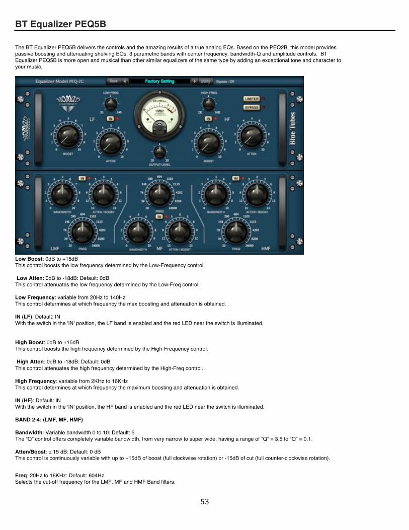
The BT Equalizer PEQ5B delivers the controls and the amazing results of a true analog EQs. Based on the PEQ2B, this model provides passive boosting and attenuating shelving EQs, 3 parametric bands with center frequency, bandwidth-Q and amplitude controls. BT Equalizer PEQ5B is more open and musical than other similar equalizers of the same type by adding an exceptional tone and character to your music.
Low Boost: 0dB to +15dB This control boosts the low frequency determined by the Low-Frequency control. Low Atten: 0dB to -18dB: Default: 0dB This control attenuates the low frequency determined by the Low-Freq control. Low Frequency: variable from 20Hz to 140Hz This control determines at which frequency the max boosting and attenuation is obtained. IN (LF): Default: IN With the switch in the 'IN' position, the LF band is enabled and the red LED near the switch is illuminated. High Boost: 0dB to +15dB This control boosts the high frequency determined by the High-Frequency control. High Atten: 0dB to -18dB: Default: 0dB This control attenuates the high frequency determined by the High-Freq control. High Frequency: variable from 2KHz to 16KHz This control determines at which frequency the maximum boosting and attenuation is obtained. IN (HF): Default: IN With the switch in the 'IN' position, the HF band is enabled and the red LED near the switch is illuminated. BAND 2-4: (LMF, MF, HMF) Bandwidth: Variable bandwidth 0 to 10: Default: 5 The “Q” control offers completely variable bandwidth, from very narrow to super wide, having a range of “Q” = 3.5 to “Q” = 0.1. Atten/Boost: ± 15 dB: Default: 0 dB This control is continuously variable with up to +15dB of boost (full clockwise rotation) or -15dB of cut (full counter-clockwise rotation).
Freq: 20Hz to 16KHz: Default: 604Hz Selects the cut-off frequency for the LMF, MF and HMF Band filters.

! &%!
IN: Default: IN With the switch in the 'IN' position, the selected band is enabled and the red LED near the switch is illuminated.
Output Level (Trim): -20dB to +20dB: Default: 0dB Sets the overall output level of the effect. This control is useful to adjust the output level again after its been reduced or boosted from applying equalization to the signal. (± 20dB) Limiter: On or Off: Default: On This switch engages the output 'Brick Wall' limiter. The 'Brick Wall' limiter or Peak. Remover is set to 0 dB. Bypass Switch: With the switch in the 'On' position, the equalizer is removed from the signal path, and the red LED near the switch is illuminated.

! &&!
BT Equalizer PEQ332 BT Equalizer PEQ322: Specially designed to meet the most demanding studio tracks, the BT Equalizer PEQ322 features 3 parametric bands with center frequency, bandwidth-Q and amplitude controls, high-pass and low-pass filters as well as low-shelf and high-shelf filters. The BT Equalizer PEQ322 delivers the controls and the amazing results of a true analog EQ. The PEQ322 is the perfect choice when a truly vintage EQ sound is what your music requires.
Q (Band 1): Variable bandwidth 1.5 to 0.1: Default: 0.8 The “Q” control offers completely variable bandwidth, from very narrow to super wide, having a range of “Q” = 1.5 to “Q” = 0.1. Gain (Band 1): ± 15 dB: Default: 0 dB The LF band (shelving response) has a boost/cut control. The control is continuously variable with up to +15dB of boost (full clockwise rotation) or -15dB of cut (full counter-clockwise rotation).
Freq (Band 1): 20 Hz to 450 Hz: Default: 245 Hz Selects the cut-off frequency for the LF Band filter section. IN (Band 1): Default: IN With the switch in the 'IN' position, the LF band is enabled and the red LED near the switch is illuminated. Q (Band 2): Variable bandwidth 3.5 to 0.1: Default: 1.8 The “Q” control offers completely variable bandwidth, from very narrow to super wide, having a range of “Q” = 3.5 to “Q” = 0.1. Gain (Band 2): ± 15 dB: Default: 0 dB The LMF band (peaking response) has a boost/cut control. The control is continuously variable with up to +15dB of boost (full clockwise rotation) or -15dB of cut (full counter-clockwise rotation).
Freq (Band 2): 200 Hz to 2.5 KHz: Default: 1.36 KHz Selects the cut-off frequency for the LMF Band filter section. IN (Band 2): Default: IN With the switch in the 'IN' position, the LMF band is enabled and the red LED near the switch is illuminated. Q (Band 3): Variable bandwidth 3.5 to 0.1: Default: 1.8 The “Q” control offers completely variable bandwidth, from very narrow to super wide, having a range of “Q” = 3.5 to “Q” = 0.1. Gain (Band 3): ± 15 dB: Default: 0 dB The MF band (peaking response) has a boost/cut control. The control is continuously variable with up to +15dB of boost (full clockwise rotation) or -15dB of cut (full counter-clockwise rotation).

! &'!
Freq (Band 3): 400 Hz to 5.5 KHz: Default: 3 KHz Selects the cut-off frequency for the MF Band filter section. IN (Band 3): Default: IN With the switch in the 'IN' position, the MF band is enabled and the red LED near the switch is illuminated. Q (Band 4): Variable bandwidth 3.5 to 0.1: Default: 1.8 The “Q” control offers completely variable bandwidth, from very narrow to super wide, having a range of “Q” = 3.5 to “Q” = 0.1. Gain (Band 4): ± 15 dB: Default: 0 dB The HMF band (peaking response) has a boost/cut control. The control is continuously variable with up to +15dB of boost (full clockwise rotation) or -15dB of cut (full counter-clockwise rotation).
Freq (Band 4): 600 Hz to 7.5 KHz: Default: 4.1 KHz Selects the cut-off frequency for the HMF Band filter section. IN (Band 4): Default: IN With the switch in the 'IN' position, the HMF band is enabled and the red LED near the switch is illuminated. Q (Band 5): Variable bandwidth 1.5 to 0.1: Default: 0.8 The “Q” control offers completely variable bandwidth, from very narrow to super wide, having a range of “Q” = 1.5 to “Q” = 0.1. Gain (Band 5): ± 15 dB: Default: 0 dB The HF band (shelving response) has a boost/cut control. The control is continuously variable with up to +15dB of boost (full clockwise rotation) or -15dB of cut (full counter-clockwise rotation).
Freq (Band 5): 1.5 KHz to 16 KHz: Default: 8.9 KHz Selects the cut-off frequency for the HF Band filter section. IN (Band 5): Default: IN With the switch in the 'IN' position, the HF band is enabled and the red LED near the switch is illuminated. HPF Selector: This control determines the frequency of the high pass filter, 5 frequencies are available: 20, 30, 40, 60, 80 Hz LPF Selector: This control determines the frequency of the low pass filter, 5 frequencies are available: 10, 12, 14, 16, 18 Khz Meter: IN, OUT: Default: OUT Determines the mode of the VU Meters. When set OUT, the VU Meters indicates the output level in dB. When set to IN, the VU Meters indicates the input level in dB. Limiter: On or Off: Default: On This switch engages the output 'Brick Wall' limiter. The 'Brick Wall' limiter or Peak Remover is set to 0 dB. Bypass Switch: With the switch in the 'On' position, the equalizer is removed from the signal path, and the red LED near the switch is illuminated.

! &(!
BLUE TUBES ANALOG TRACKBOX The Blue Tubes Analog TrackBox is not an update or a replacement for our very popular Blue Tubes Bundle, but a complementary unit that incorporates a substantially different combination of elements. The Blue Tubes Analog TrackBox is an all-purpose channel strip tool designed to maximize sound quality and audio character for total musical flexibility. Nomad Factory designs and builds the most powerful and efficient audio processing tools for pro audio applications. Including dynamics processors, equalizers and effects, Nomad Factory delivers the highest quality tube emulation plug-ins without sacrificing ease-of-use or affordability.

! &)!
TUBE EMULATION SECTION The Tube-Emulator section has the unique option of being able to switch between two different sounding tube options from Single-Triode to Dual-Triode. The independent Amount and Color controls permit overdrive of the Tube-Emulator stage to vary the harmonic content of the signal.
Amount: 0 to 100 %: Default: 34 % This sets the amount of drive from the Tube 12AX7, allowing you to sweeten and personalize your sound by adding the desired amount of harmonics to the original signal. Additional harmonics are produced by slightly overdriving the tube stage. The more you turn the Amount control to the right, the more tube sound will be added to the original signal. Color: -10 to 10; Default: 0 Controls the color of the tube sound. Turning the Color control to the right emulates the sound of triode tube distortion. Turning the control to the left emulates the sound of analog tube-tape-recorder. Triode: Single to Dual: Default: 1.5 Determines the number of stages from the 12AX7 (twin triode). When set to the right (Dual-Triode), additional harmonics are produced by overdriving the second tube stage, the output signal coming from tube-stage one is re-injected into tube-stage two. Increasing tube saturation produces a slight compression effect, this saturation effect can be perceived when analog tape is saturated. IN: Default: Off With the switch in the 'IN' position, the tube section is enabled and the red LED near the top switch is illuminated.

! &*!
GATE SECTION The Gate/Expander section tames the noise floor so that you hear only the audio you want to keep. This fully adjustable gate/expander reduces (or cuts) the signal if the level becomes too low (as determined by the Gate Threshold setting). This controls unwanted background noise on the track(s). Like a compressor, the Attack and Release controls determine how fast the gate opens and close.
Threshold: 0 to -60 dB: Default: 0 dB Sets the decibel (dB) threshold to the level at which the gate begins to open. (i.e., allow the signal to pass through un-attenuated) Attack: 0.2 to 400 ms: Default: 0.2 ms This control determines how quickly the gate opens; the fastest Attack time ensures that the gate does not clip the leading edge of extremely fast transients. Release: 50 to 2000 ms; Default: 200 ms Controls how long (ms) it takes the gate to close, once the signal has fallen below the Threshold. IN: Default: Off With the switch in the 'IN' position, the gate section is enabled and the red LED near the top switch is illuminated.
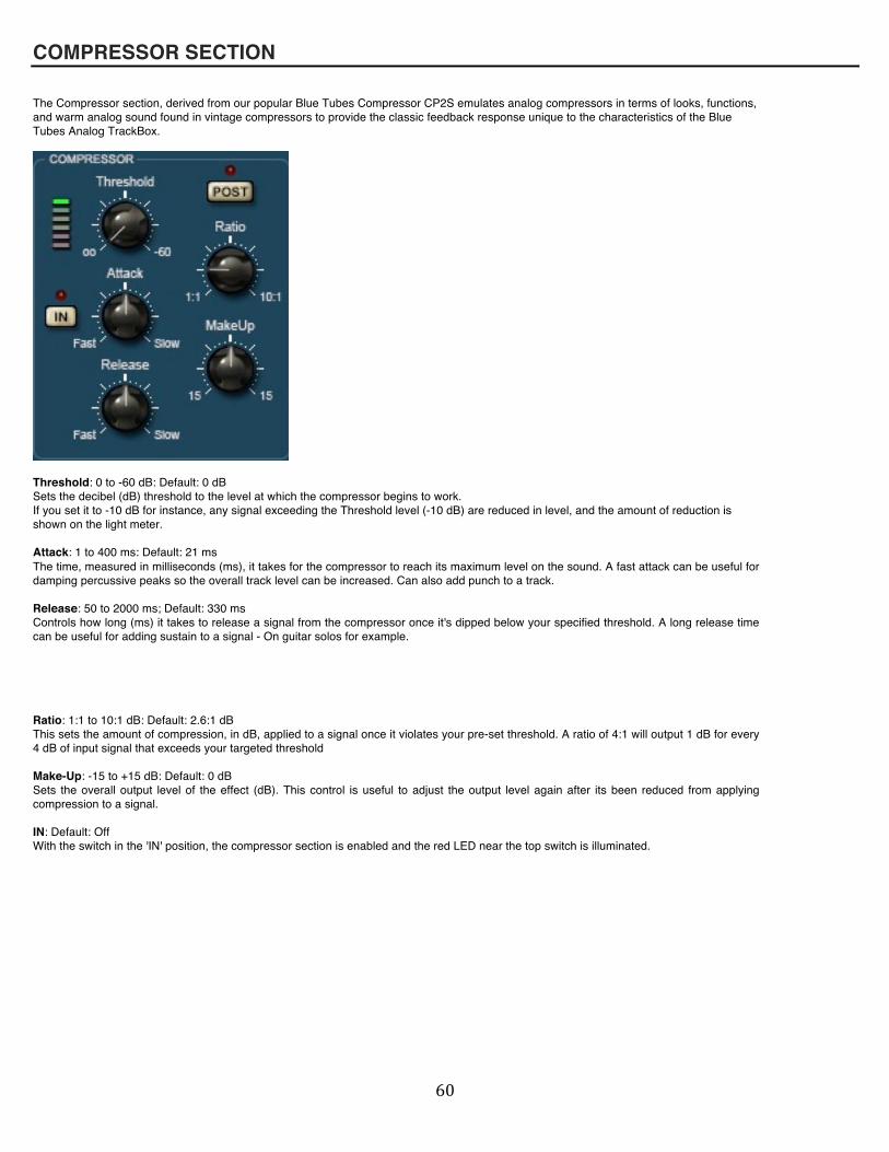
! '+!
COMPRESSOR SECTION The Compressor section, derived from our popular Blue Tubes Compressor CP2S emulates analog compressors in terms of looks, functions, and warm analog sound found in vintage compressors to provide the classic feedback response unique to the characteristics of the Blue Tubes Analog TrackBox.
Threshold: 0 to -60 dB: Default: 0 dB Sets the decibel (dB) threshold to the level at which the compressor begins to work. If you set it to -10 dB for instance, any signal exceeding the Threshold level (-10 dB) are reduced in level, and the amount of reduction is shown on the light meter. Attack: 1 to 400 ms: Default: 21 ms The time, measured in milliseconds (ms), it takes for the compressor to reach its maximum level on the sound. A fast attack can be useful for damping percussive peaks so the overall track level can be increased. Can also add punch to a track. Release: 50 to 2000 ms; Default: 330 ms Controls how long (ms) it takes to release a signal from the compressor once it's dipped below your specified threshold. A long release time can be useful for adding sustain to a signal - On guitar solos for example. Ratio: 1:1 to 10:1 dB: Default: 2.6:1 dB This sets the amount of compression, in dB, applied to a signal once it violates your pre-set threshold. A ratio of 4:1 will output 1 dB for every 4 dB of input signal that exceeds your targeted threshold Make-Up: -15 to +15 dB: Default: 0 dB Sets the overall output level of the effect (dB). This control is useful to adjust the output level again after its been reduced from applying compression to a signal. IN: Default: Off With the switch in the 'IN' position, the compressor section is enabled and the red LED near the top switch is illuminated.

! '"!
EQUALIZER SECTION The Equalizer section, derived from the Blue Tubes PEQ322 is designed to meet the most demanding studio tracks, features 2 parametric bands with center frequency, bandwidth-Q and amplitude controls as well as low-shelf and high-shelf filters. The Equalizer section delivers the controls and the amazing results of a true analog EQ.
Q (Band 1 to Band 4): Variable bandwidth 0.1 to 1.5: Default: 0.8 The “Q” control offers completely variable bandwidth, from very narrow to super wide. Gain (Band 1 to Band 4): ± 15 dB: Default: 0 dB The LF band (shelving response) has a boost/cut control. The control is continuously variable with up to +15dB of boost (full clockwise rotation) or -15dB of cut (full counter-clockwise rotation). Freq (Band 1): 40 Hz to 600 Hz: Default: 64 Hz Selects the cut-off frequency for the EQ Band 1 filter section. Freq (Band 2): 200 Hz to 2.5 KHz: Default: 500 Hz Selects the cut-off frequency for the EQ Band 2 filter section. Freq (Band 3): 600 Hz to 7.5 KHz: Default: 2.2 KHz Selects the cut-off frequency for the EQ Band 3 filter section. Freq (Band 4): 1.5 KHz to 16 KHz: Default: 7.4 KHz Selects the cut-off frequency for the EQ Band 4 filter section. IN: Default: Off With the switch in the 'IN' position, the equalizer section is enabled and the red LED near the top switch is illuminated. Low/High Pass – Master Section HPF Selector: This control determines the frequency of the high pass filter, 5 frequencies are available: 20, 30, 40, 60, 80 Hz LPF Selector: This control determines the frequency of the low pass filter, 5 frequencies are available: 10, 12, 14, 16, 18 Khz Input Level: ± 15 dB: Default: 0 dB Sets the overall input level of the effect (dB). Output Level: ± 15 dB: Default: 0 dB Sets the overall output level of the effect (dB). This control is useful to adjust the output level again after its been reduced or boosted from applying Tube, Gate, Compressor and Equalization to the signal. Phase Switch: Inverts the phase of the Blue Tubes Analog TrackBox. Limit Switch: On or Off: Default: On This switch engages the output 'On' position, Brick Wall' limiter. The 'Brick Wall' limiter or Peak Remover is set to 0 dB. Meter: Left, Right: Default: Left Determines the mode of the VU Meters. When set Left, the VU Meters indicates the left input/output levels in dB. When set to Right, the VU Meters indicates the Right channel input/output levels in dB. Bypass Switch: With the switch in the 'On' position, the Blue Tubes Analog TrackBox is removed from the signal path, and the red LED near the switch is illuminated.

! '#!
BLUEVERB DRV-2080 BlueVerb DRV-2080 Controls: 1- PreDelay:
Pre-Dly: - This control introduces a delay before the reverb effect: 0 ms / 999 ms 2- Ambiance / Amount:
Ambiance: - This control alters the character of the reverberation, can also be named early reflections, this control can reproduce the 'Ambiance' of Lexicons ambiance patches. Amount: - This control determines the level of early reflections. (Ambiance) (0 - 100%)
3- Decay-RT60 / Damping:
Decay-RT60: - The Decay-RT60 sets the reverberation time (in seconds) 0.5 to 10 sec Damping: - This controls the high frequency damping. Turning the knob to the left = dark Turning the knob to the right = bright 4- Tail Level / Stereo Width:
Tail Level: - This control determines the level of the classic reverberation. (0 - 100%) Stereo Width: - This control determines the stereo image of the reverberation. Turning the knob to the left = Mono Turning the knob to the right = Stereo

! '$!
5- Equalizer:
Low Gain: This control determines the amount of low shelving gain or cut to be applied to the frequency set by the Frequency switch. (+-15dB) Low Freq: This control determines the frequency of the low portion of the equalizer. 50 Hz to 800 Hz High Gain: This control determines the amount of high shelving gain or cut to be applied to the frequency set by the Frequency switch. (+-15dB) High Freq: This control determines the frequency of the low portion of the equalizer. 1Khz to 8 Khz On/Off Switch: This switch enables or disables the equalizer. 6- Master Levels:
Input: This control determines the input level of the BlueVerb DRV-2080. Output: This control determines the output level of the BlueVerb DRV-2080. Mix: The Mix control is used to control the mix between the unprocessed input and the reverberated output.
7- Divers:
Rev A / Rev B: This switch determines the quality and CPU usage of the reverberation. Rev A = less CPU (Good Quality Processing) Rev B = more CPU (High Quality Processing) 7- Power:
Turns On/Off the BlueVerb DRV-2080 (Bypass).

! '%!
ESSENTIAL STUDIO SUITE
Essential Channel
The Essential Channel delivers maximum processing flexibility with minimum space required. The most critical channel processing functions are provided in a single plug-in: 3-band parametric EQ, High and Low Shelf filters, High and Low Pass Filters, Peak or RMS Compression (Pre- or Post EQ), DeEsser (with selectable High-Pass or Band-Pass Filter), Noise Gate, and Brick-Wall Limiting. Additional features include L/R Swap and Phase Inversion (both or L/R channels individually), and Mode selection.
The controls and features of the Essential Channel are described below:
Equalizer On/Off (Equalizer section)
• Square button that turns the EQ on and off; yellow is “on”
HPF (Equalizer section)
• Selects the cutoff frequency for the High Pass Filter above which the signal passes un-attenuated
LPF (Equalizer section)
• Selects the cutoff frequency for the Low Pass Filter below which the signal passes un-attenuated
Low Shelf Gain (Equalizer section)
• Adjusts the amount of boost (+24dB) or cut (-24dB) below the selected frequency
Low Shelf On/Off (Equalizer section) • Square button that turns the Low Shelf EQ on and off; yellow is “on”
Low Shelf Freq (Equalizer section)
• Selects the frequency for the Low Shelf EQ (20Hz - 400Hz)
MLF/MF/MHF On/Off (Equalizer section)
• Square button that turns the MLF (mid-low freq.), MF (mid freq.), or MHF (mid-high freq.) EQ on and off; yellow is “on”

! '&!
MLF/MF/MHF Gain (Equalizer section)
• Adjusts the amount of boost (+24dB) or cut (-24dB) for the corresponding frequency band
MLF/MF/MHF Freq (Equalizer section)
• Selects the center frequency for the corresponding frequency band (MLF: 30Hz - 600Hz; MF: 100Hz - 6kHz; MHF: 600Hz - 18kHz)
MLF/MF/MHF BW (Equalizer section)
• Controls the bandwidth of the corresponding frequency band (.1 - 2.0)
High Shelf On/Off (Equalizer section)
• Square button that turns the High Shelf EQ on and off; yellow is “on”
High Shelf Gain (Equalizer section)
• Adjusts the amount of boost (+24dB) or cut (-24dB) above the selected frequency
High Shelf Freq (Equalizer section)
• Selects the frequency for the High Shelf EQ (2kHz - 20kHz)
Compressor On/Off (Compressor section)
• Square button that turns the Compressor on and off; yellow is “on”
Threshold (Compressor section)
• Controls the threshold level (in dB) for the compressor; this is the level above which the compressor begins to attenuate the signal
Ratio (Compressor section)
• Controls the compression ratio for the compressor; this is the ratio of input to output levels Attack (Compressor section)
• Controls how fast the compressor begins to attenuate the signal after exceeding the Threshold
Release (Compressor section)
• Controls how long the compressor takes to return the signal to the unattenuated level
Makeup (Compressor section)
• Controls the make-up gain for the compressor
Atten (Compressor section)
• Meter that displays the amount of signal attenuation by the compressor
Pre EQ/Post EQ (Compressor section)
• Button that toggles between Pre EQ (compression applied before the EQ section) and Post EQ (compression applied after the EQ section)

! ''!
RMS/Peak (Compressor section)
• Button that toggles between RMS compression and Peak compression
DeEsser On/Off (DeEsser section)
• Square button that turns the DeEsser on and off; yellow is “on”
Freq (DeEsser section)
• Sets the cutoff frequency above which the DeEsser attenuates the signal if the level exceeds the Threshold (see “Threshold” below); the “Listen” button must be off for the DeEsser to operate properly (see “Listen” below)
Threshold (DeEsser section)
• Sets the threshold level (in dB); the DeEsser attenuates signal levels that exceed both the threshold and the frequency (see “Freq” above)
Attack (DeEsser section)
• Controls how fast the DeEsser begins to attenuate the signal once the threshold and frequency is exceeded Atten (DeEsser section)
• Meter that displays the amount of signal attenuation by the DeEsser
HPF/BPF (DeEsser section)
• Button that toggles the DeEsser between a High-Pass Filter and a Band-Pass Filter
Listen (DeEsser section)
• Button that outputs only the frequencies above the selected frequency; this allows you to solo the signal that will be attenuated by the DeEsser
Threshold (Noise Gate section)
• Controls the threshold level (in dB) for the Noise Gate; this is the level the signal must exceed in order to open the gate (i.e., allow the signal to pass through unattenuated)
Attack (Noise Gate section)
• Controls how fast the Noise Gate opens after the signal exceeds the Threshold
Release (Noise Gate section)
• Controls how long the Noise Gate takes to close (i.e., cut the signal)
Atten (Noise Gate section)
• Meter that displays whether the gate is open (green) or closed (red)
Input (Master section)
• Adjusts the input level to the Essential Channel
Output (Master section)

! '(!
• Adjusts the output level from the Essential Channel
Limiter (Master section)
• Applies a Limiter to the output of the Essential Channel
Swap L/R (Master section)
• Swaps the Left and Right channels of the stereo signal Phase (Master section)
• Inverts the phase of the output (Invert), or inverts only the Left (Invert L) or Right (Invert R) channels independently; Normal = no phase inversion
Mode (Master section)
• Changes the overall sound to the output of the Essential Channel; options include Warm, Fat, Dirty, Hard; Clean = no change to the output
Mono (Master section)
• Sums the stereo output signal to mono
Bypass (Master section)
• Turns off the Essential Channel
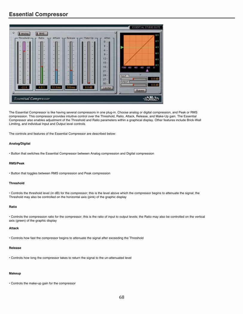
! ')!
Essential Compressor
The Essential Compressor is like having several compressors in one plug-in. Choose analog or digital compression, and Peak or RMS compression. This compressor provides intuitive control over the Threshold, Ratio, Attack, Release, and Make-Up gain. The Essential Compressor also enables adjustment of the Threshold and Ratio parameters within a graphical display. Other features include Brick-Wall Limiting, and individual Input and Output level controls.
The controls and features of the Essential Compressor are described below:
Analog/Digital
• Button that switches the Essential Compressor between Analog compression and Digital compression
RMS/Peak
• Button that toggles between RMS compression and Peak compression
Threshold
• Controls the threshold level (in dB) for the compressor; this is the level above which the compressor begins to attenuate the signal; the Threshold may also be controlled on the horizontal axis (pink) of the graphic display
Ratio
• Controls the compression ratio for the compressor; this is the ratio of input to output levels; the Ratio may also be controlled on the vertical axis (green) of the graphic display Attack
• Controls how fast the compressor begins to attenuate the signal after exceeding the Threshold
Release
• Controls how long the compressor takes to return the signal to the un-attenuated level
Makeup
• Controls the make-up gain for the compressor

! '*!
Atten
• Meter that displays the amount of signal attenuation by the compressor
Limiter
• Applies a Limiter to the output of the compressor
Input
• Adjusts the input level to the Essential Compressor
Output
• Adjusts the output level from the Essential Compressor
Bypass
• Turns off the Essential Compressor

! (+!
Essential Gate/Expander
The Essential Gate/Expander tames the noise floor so that you hear only the audio you want to keep. This fully-adjustable gate/expander allows control of Threshold, Attack, Hold, Release and Range. Left and Right VU meters and controls for Input and Output round out the feature list for this essential studio plug-in.
The controls and features of the Essential Gate/Expander are described below:
Threshold
• Controls the threshold level (in dB) for the gate; this is the level the signal must exceed in order to open the gate (i.e., allow the signal to pass through un-attenuated)
Attack
• Controls how fast the gate opens after the signal exceeds the Threshold
Hold
• Controls how long the gate stays open after the signal has dropped below the threshold
Release
• Controls how long the gate takes to close (i.e., cut the signal)
Range
• Controls the amount of signal reduction by the gate
Atten
• Meter that displays whether the gate is open (blue) or closed (red)
In/Out/Off
• Selects the source for the VU Meters above; In = input, Out = output, Off = VU Meter off
Input
• Adjusts the input level to the Essential Gate/Expander

! ("!
Output
• Adjusts the output level from the Essential Gate/Expander
Bypass
• Turns off the Essential Gate/Expander

! (#!
Essential Graphic EQ
The Essential Graphic EQ is the perfect tool for sculpting the fine detail out of raw digital audio. 15 frequency bands, adjustable bandwidth and brick-wall limiter allow for precise sound definition in your mixes or mastered tracks.
The controls and features of the Essential Graphic EQ are described below:
Frequency Bands
• 15 sliders that control the amount of boost (+24dB) or cut (-24dB) for specific frequency bands indicated at the top of each slider
Band
• Adjusts the bandwidth around the center frequencies (or corner frequencies in the case of the 40Hz and 16kHz bands)
In/Out/Off
• Selects the source for the VU Meter above; In = input, Out = output, Off = VU Meter off
Input
• Adjusts the input level to the Essential Graphic EQ
Output
• Adjusts the output level from the Essential Graphic EQ Limiter
• Applies a Limiter to the output of the Essential Graphic EQ
Bypass
• Turns off the Essential Graphic EQ
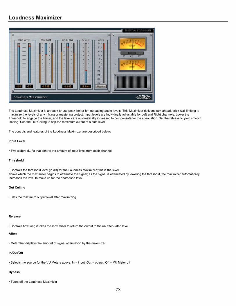
! ($!
Loudness Maximizer
The Loudness Maximizer is an easy-to-use peak limiter for increasing audio levels. This Maximizer delivers look-ahead, brick-wall limiting to maximize the levels of any mixing or mastering project. Input levels are individually adjustable for Left and Right channels. Lower the Threshold to engage the limiter, and the levels are automatically increased to compensate for the attenuation. Set the release to yield smooth limiting. Use the Out Ceiling to cap the maximum output at a safe level.
The controls and features of the Loudness Maximizer are described below:
Input Level
• Two sliders (L, R) that control the amount of input level from each channel
Threshold
• Controls the threshold level (in dB) for the Loudness Maximizer; this is the level above which the maximizer begins to attenuate the signal; as the signal is attenuated by lowering the threshold, the maximizer automatically increases the level to make up for the decreased level
Out Ceiling
• Sets the maximum output level after maximizing
Release
• Controls how long it takes the maximizer to return the output to the un-attenuated level Atten
• Meter that displays the amount of signal attenuation by the maximizer
In/Out/Off
• Selects the source for the VU Meters above; In = input, Out = output, Off = VU Meter off
Bypass
• Turns off the Loudness Maximizer

! (%!
Multiband Compressor
The Multiband Compressor brings together all the vital controls of multiband compression within this easy-to-use interface. With 3-band compression, Brick-Wall limiting, L/R Swap and Curve Mode EQ, this compressor is a powerful and flexible solution for any mixing or mastering project. Move the crossovers to define the frequency bands, adjust the gain, add compression and solo each band individually to create your sound with precision.
The controls and features of the Multiband Compressor are described below:
Low - Mid - High (Crossover section)
• Displays the frequencies dividing the Low from the Mid bands, and the Mid from the High bands; on the graphic frequency display, click and drag in the Low band to adjust the Low-Mid crossover frequency; click and drag in the High band to adjust the Mid-High crossover frequency; click and drag the entire Mid band to change both crossovers simultaneously.
Low/Mid/High Gain (Crossover section)
• Controls the make-up gain for each compressor (C1, C2, C3) corresponding to the three frequency bands
Low/Mid/High Solo (Crossover section)
• Square button that solos the corresponding frequency band; yellow is “on”
C1/C2/C3 On/Off (Compressor section)
• Square button that turns the Compressor (C1, C2, or C3) on and off; yellow is “on”
C1/C2/C3 Peak/RMS
• Toggles between Peak or RMS compression for the corresponding compressor (C1, C2 & C3)
C1/C2/C3 Threshold
• Controls the threshold level (in dB) for the corresponding compressor (C1, C2 & C3); this is the level above which the compressor begins to attenuate the signal

! (&!
C1/C2/C3 Ratio
• Controls the compression ratio for the corresponding compressor (C1, C2 & C3); this is the ratio of input to output levels
C1/C2/C3 Attack
• Controls how fast the signal begins to attenuate once the threshold is exceeded for the corresponding compressor (C1, C2 & C3)
C1/C2/C3 Release
• Controls how long the compressor takes to return the signal to the un-attenuated level for the corresponding compressor (C1, C2 & C3)
Input (Master section)
• Adjusts the input level to the multiband compressor
Output (Master section)
• Adjusts the output level from the multiband compressor
Curve Mode (Master section)
• Applies a pre-defined EQ curve to the signal path (Linear, Hi Boost, Lo Boost, Hi Atten, Lo Atten, Smile, Sad)
Limiter (Master section)
• Applies a Limiter after the EQ curve
Swap L/R (Master section)
• Swaps the Left and Right channels of the stereo signal
Mono (Master section)
• Sums the stereo output signal to mono
Bypass (Master section)
• Turns off the Multiband Compressor

! ('!
Multiband Loudness Maximizer
The Multiband Loudness Maximizer brings the sound of professional mastering to any audio application. The multiband maximizer from Nomad Factory delivers three frequency bands of look-ahead, brick-wall limiting to precisely control and maximize the output levels of a recording. Input levels are individually adjustable for Low, Mid and High bands, and the crossovers can be moved to precisely define the frequency bands. Lower the Threshold to engage the limiter, and the levels are automatically increased to compensate for the attenuation. Set the release to yield smooth limiting. Once you have set the right amount of limiting/attenuation, you can even add more level to the output to give you all the volume you could want.
The controls and features of the Multiband Loudness Maximizer are described below:
Low - Mid - High (Crossover section)
• Displays the frequencies dividing the Low from the Mid bands, and the Mid from the High bands; on the graphic frequency display, click and drag in the Low band to adjust the Low-Mid crossover frequency; click and drag in the High band to adjust the Mid-High crossover frequency; click and drag the entire Mid band to change both cross-overs simultaneously
Input Level L/M/H
• Each slider (L, M, H) controls the amount of level input into each of the three frequency bands (High, Mid, Low)
Threshold
• Controls the threshold level (in dB) for the Multiband Loudness Maximizer; this is the level above which the maximizer begins to attenuate the signal; as the signal is attenuated by lowering the threshold, the maximizer automatically increases the level to make up for the decreased level; this smooths out the transient peaks allowing for increased output level (see “Output Level” below)
Output Level
• Allows you to add increased level to the output after attenuation
Release
• Controls how long it takes the maximizer to return the output to the un-attenuated level

! ((!
Atten
• Meter that displays the amount of signal attenuation by the maximizer
Bypass
• Turns off the Multiband Loudness Maximizer
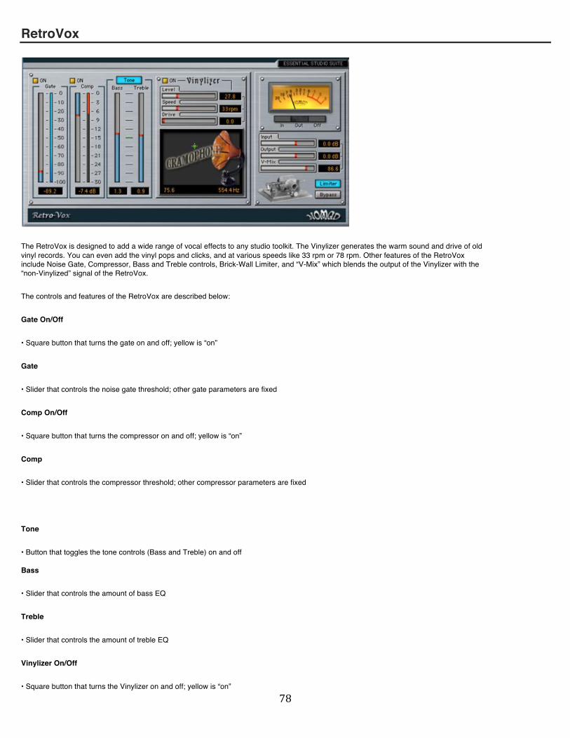
! ()!
RetroVox
The RetroVox is designed to add a wide range of vocal effects to any studio toolkit. The Vinylizer generates the warm sound and drive of old vinyl records. You can even add the vinyl pops and clicks, and at various speeds like 33 rpm or 78 rpm. Other features of the RetroVox include Noise Gate, Compressor, Bass and Treble controls, Brick-Wall Limiter, and “V-Mix” which blends the output of the Vinylizer with the “non-Vinylized” signal of the RetroVox.
The controls and features of the RetroVox are described below:
Gate On/Off
• Square button that turns the gate on and off; yellow is “on”
Gate
• Slider that controls the noise gate threshold; other gate parameters are fixed
Comp On/Off
• Square button that turns the compressor on and off; yellow is “on”
Comp
• Slider that controls the compressor threshold; other compressor parameters are fixed
Tone
• Button that toggles the tone controls (Bass and Treble) on and off Bass
• Slider that controls the amount of bass EQ
Treble
• Slider that controls the amount of treble EQ
Vinylizer On/Off
• Square button that turns the Vinylizer on and off; yellow is “on”

! (*!
Level
• Controls the level of the pops and clicks in the Vinylizer output
Speed
• Controls the speed of the Vinylizer; this simulates a vinyl record spinning at various speeds (16 rpm - 78 rpm)
Drive
• Adjusts the amount of overdrive in the Vinylizer sound
“Gramophone”
• Graphical display used to create various filter effects, such as “Phone Voice”; drag the green cursor around the square graphic to hear the filtering effects
In/Out/Off
• Selects the source for the VU Meter above; In = input, Out = output, Off = VU off
Input
• Adjusts the input level to the RetroVox
Output
• Adjusts the output level from the RetroVox
V-Mix
• Adjusts the output level from the Vinylizer section Limiter
• Applies a Limiter to the output of the RetroVox
Bypass
• Turns off the RetroVox

! )+!
Tube/Tape Warmer
Digital audio can sometimes sound lifeless or brittle. Add some analog warmth and drive to those tracks with Nomad Factoryʼs Tube/Tape Warmer. This effect gives sterile audio the coveted sounds of tube circuitry and analog tape saturation. Engage the 12AX7 tubes (A or B) and increase the drive control individually for extra bite. You can independently add the sound of analog tape rolling at 30 or 15 ips. Use the Tone control to dial in just the right amount of high or low frequencies to highlight the added warmth.
The controls and features of the Tube/Tape Warmer are described below:
12AX7 A/B
• Controls the amount of drive from the tubes; click to engage Tube A and/or Tube B buttons (see below) to apply tube sound
Tone
• Adjusts the amount of high or low frequencies in the signal
Tape Speed Select (30 ips/ 15 ips)
• Toggles between two tape speed simulations: 30 inches per second or 15 inches per second
Tube A
• Button that applies the tube sound from Tube A; the drive of the tube is controlled by the slider labelled “12AX7 A”
Tube B
• Button that applies the tube sound from Tube B; the drive of the tube is controlled by the slider labelled “12AX7 B”
Tape
• Applies the sound of tape warmth to the signal; the tape sound can be changed by toggling the tape speed (see “Tape Speed Select” above)

! )"!
In/Out/Off
• Selects the source for the VU Meters above; In = input, Out = output, Off = VU Meter off
Input
• Adjusts the input level to the Tube/Tape Warmer
Output
• Adjusts the output level from the Tube/Tape Warmer
Bypass
• Turns off the Tube/Tape Warmer
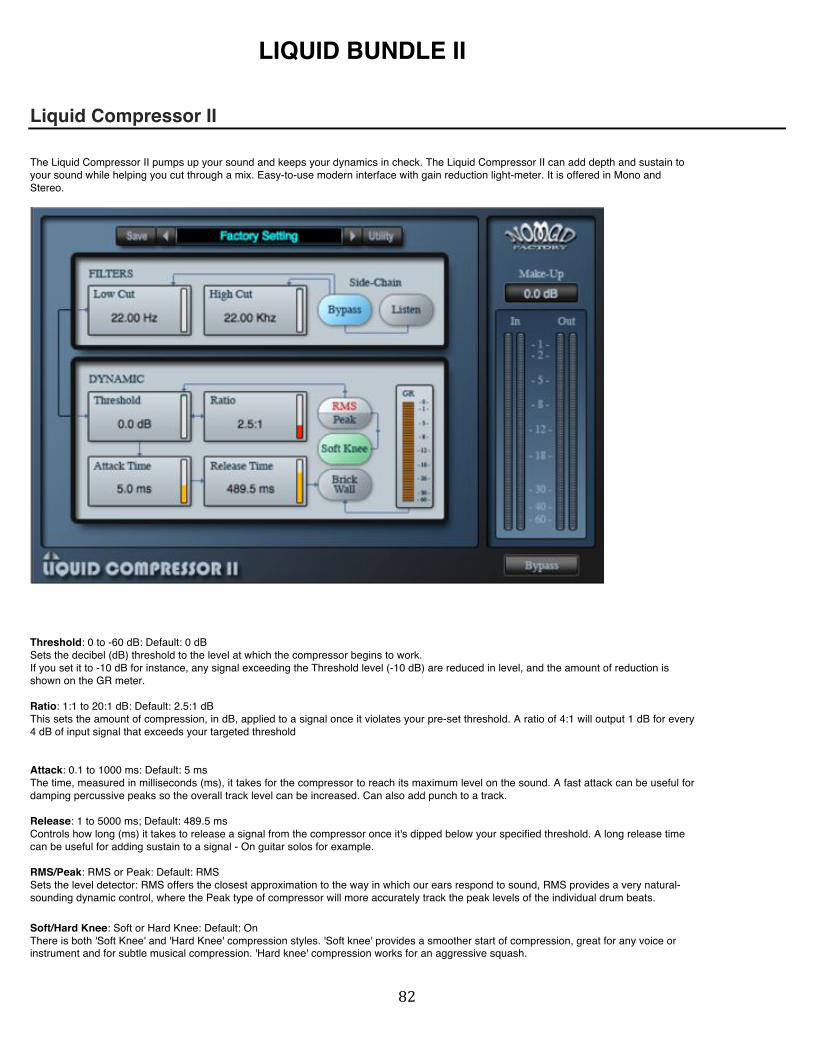
! )#!
LIQUID BUNDLE II
Liquid Compressor II
The Liquid Compressor II pumps up your sound and keeps your dynamics in check. The Liquid Compressor II can add depth and sustain to your sound while helping you cut through a mix. Easy-to-use modern interface with gain reduction light-meter. It is offered in Mono and Stereo.
Threshold: 0 to -60 dB: Default: 0 dB Sets the decibel (dB) threshold to the level at which the compressor begins to work. If you set it to -10 dB for instance, any signal exceeding the Threshold level (-10 dB) are reduced in level, and the amount of reduction is shown on the GR meter. Ratio: 1:1 to 20:1 dB: Default: 2.5:1 dB This sets the amount of compression, in dB, applied to a signal once it violates your pre-set threshold. A ratio of 4:1 will output 1 dB for every 4 dB of input signal that exceeds your targeted threshold Attack: 0.1 to 1000 ms: Default: 5 ms The time, measured in milliseconds (ms), it takes for the compressor to reach its maximum level on the sound. A fast attack can be useful for damping percussive peaks so the overall track level can be increased. Can also add punch to a track. Release: 1 to 5000 ms; Default: 489.5 ms Controls how long (ms) it takes to release a signal from the compressor once it's dipped below your specified threshold. A long release time can be useful for adding sustain to a signal - On guitar solos for example. RMS/Peak: RMS or Peak: Default: RMS Sets the level detector: RMS offers the closest approximation to the way in which our ears respond to sound, RMS provides a very natural-sounding dynamic control, where the Peak type of compressor will more accurately track the peak levels of the individual drum beats.
Soft/Hard Knee: Soft or Hard Knee: Default: On There is both 'Soft Knee' and 'Hard Knee' compression styles. 'Soft knee' provides a smoother start of compression, great for any voice or instrument and for subtle musical compression. 'Hard knee' compression works for an aggressive squash.

! )$!
Brick Wall: On or Off: Default: Off This switch engages the output Brick Wall limiter. The Brick Wall limiter is set to 0 dB. Make-Up: -36 to +36 dB: Default: 0 dB Sets the overall output level of the effect (dB). This control is useful to adjust the output level again after its been reduced from applying compression to a signal. SIDECHAIN FILTERS: To help the compressor decide when to compress, you can use the two Filter controls. The Filters only affect the signal driving the compressor, not the sound being processed, and you can use the Listen control which allows the effect of the Filters to be heard when setting up, so you'll hear a filtered version of the input in Listen mode.
Low Cut: 22 Hz to 22 KHz: Default: 22 Hz Sets the Low Cut frequency. (HPF) High Cut: 22 Hz to 22 KHz: Default: 22 Hz Sets the High Cut frequency. (LPF) Bypass - SideChain: Off or On: Default: On Turns On/Off the side chain filters (Bypass) Listen: Off or On: Default: Off This switch engages the output Brick Wall limiter. The Brick Wall limiter is set to 0 dB.

! )%!
Liquid Delays II
The Liquid Delays II is a filtered dual-delay effect plug-in, featuring two delays, resonant filters, tube saturation-overdrive, peak-limiter and LFO. The Liquid Delays II is capable of clean-delays, dirty-delays, filtered-delays, and more. From basic synced delays to dirty, grungy, distorted delayed filters, the Liquid Delays II cerates an unlimited number of amazing effects.
On - Filters: Off or On. Default: On Turns On/Off the filters section (Bypass) Low Cut: 22 Hz to 11 KHz: Default: 800.2 Hz Sets the Low Cut frequency. (HPF) Resonance: 0 to 100 %: Default: 50 % Sets the HP/LP filters' resonance. High Cut: 600 Hz to 22 KHz: Default: 2.3 KHz Sets the High Cut frequency. (LPF) Overdrive: Off to 100%: Default: Off This sets the amount of distortion-overdrive to be added to the effect. On - (In-Loop): Off or On: Default: Off
On = The direct (dry) signal will be added and processed through the filters and overdrive modules.
Off = Only the delayed (wet) signal will be filtered.
On - (Filters-modulation): Off or On: Default: Off This switch enables or disables the LFO section of the Liquid Delays II. Sync - (Filters-modulation): Off or On: Default: Off When the Sync button is On, Liquid Delays II will be synced to the hostʼs tempo. Any changes made to the hostʼs tempo will affect the plug-inʼs modulation rate in real time.

! )&!
Wave Form (Filters-modulation)): Default: Sine Sets the waveform from a range of waveforms: 1. Sine 2. Triangle 3. Square 4. Saw up 5. Saw down Rate (Filters-modulation)): 0.05 Hz to 22 Hz: Default: 1.00 Hz This control sets the frequency of the LFO in Hz. Increasing the Rate increases the oscillation speed. When the Sync button is On, Liquid Delays II will be synced to the hostʼs tempo. Any changes made to the hostʼs tempo will affect the plug-inʼs modulation rate in real time. In Sync mode, the Rate control is adjustable in musical units (bars, 1/8th notes, triplets, etc.) 1 x 8 bars 1 x 7 bars 1 x 6 bars 1 x 5 bars 1 x 4 bars 1 x 3 bars 1 x 4T Bars 1 x 2 bars 1 x 1D 1 x 2T 1 x 1 1 x 1/2D 1 x 1/2 1 x 1/4D 1 x 1/2T 1 x 1/4 1 x 1/8D 1 x 1/4T 1 x 1/8 1 x 1/16D 1 x 1/8T 1 x 1/16 1 x 1/32 Depth (Filters-modulation)): Off to 100 %: Default: 100 % The Depth control sets how deeply the filters will be swept. The depth is fixed in percentage. Peak-Limit (Master): On or Off: Default: On This switch engages the output "Brick Wall" peak limiter. The Peak Limiter is set to 0 dB. Stereo Width (Master): 0 to 100 %: Default: 100 % Sets the stereo image between left and right outputs On - (Delay-Sync): Off or On: Default: On When the button is “On” (Sync), the delays (left and right) will be synced to the hostʼs tempo. Any changes made to the hostʼs tempo will affect the delays in real time. On - (L-Delay): Off or On: Default: On This switch enables or disables the Left Delay section of the Liquid Delays II. On - (R-Delay): Off or On: Default: On This switch enables or disables the Right Delay section of the Liquid Delays II. Tempo (Delays): 40 to 500 bmp / Sync: Default: Sync or 120 bmp. When the Sync button is “On”, delay section will be synced to the hostʼs tempo. Any changes made to the hostʼs tempo will affect the tempo of the delays in real time. Feedback (Delays): Off to 100%: Default: 33 % Controls how much of the wet signal is looped back through the delays section. L-Delays (Delays): Selects the note value that sets the delay rhythm for the left channel. This setting refers to the Tempo value to determine the delay time. Values range from whole notes to Thirty-second note, and include triplets and dotted notes. R-Delays (Delays): Selects the note value that sets the delay rhythm for the left channel. This setting refers to the Tempo value to determine the delay time. Values range from whole notes to Thirty-second note, and include triplets and dotted notes.

! )'!
Mode (Routing): Controls the order on how the effects (sections) will be processed. - Drive -> Filters -> Delays - Drive -> Delays -> Filters - Delays -> Filters -> Drive - Delays -> Drive -> Filters - Filters -> Delays -> Drive - Filters -> Drive -> Delays
Input Level: -24 to +24 dB: Default: 0 dB This control determines the input level of the Liquid Delays II Output Level: -24 to +24 dB: Default: 0 dB This control determines the output level of the Liquid Delays II Mix: 0% to 100%: Default: 50% Controls the mix between the processed wet signal and dry input signal.

! )(!
Liquid Gate II The Liquid Gate II tames the noise floor so that you hear only the audio you want to keep. This fully adjustable gate/expander allows control of Threshold, Attack Time, Hold Time, Release Time and Range. To help the gate decide when to open, you can use the two Filter controls (SideChain). Easy-to-use modern interface with gain reduction light-meter. It is offered in Mono and Stereo.
Threshold: 0 to -60 dB: Default: -21.6 dB Sets the decibel (dB) threshold to the level at which the gate begins to open. (i.e., allow the signal to pass through un-attenuated) Range: 0 to 100%: Default: 100% This sets the amount of signal reduction by the gate in percents. If you set it to 10% for instance, when closed, the gate will allow 10 % of the audio level goes thru the plug-in. Attack Time: 0.1 to 1000 ms: Default: 5 ms This control determines how quickly the gate opens, the fastest Attack time ensures that the gate does not clip the leading edge of extremely fast transients. Hold Time: 0.0 to 2000 ms: Default: 0.0 ms This control determines the amount of time the gate is held open after the signal falls below the Threshold. Release Time: 10 to 5000 ms; Default: 50 ms Controls how long (ms) it takes the gate to close, once the signal has fallen below the Threshold and the Hold time has expired. RMS/Peak: RMS or Peak: Default: RMS Sets the level envelope detector: RMS provides a very natural control of the gate, where the Peak type will more accurately track the peak levels of the individual drum beats.
SIDECHAIN FILTERS: To help the gate decide when to open, you can use the two Filter controls. The Filters only affect the signal driving the gate, not the sound being processed, and you can use the Listen control which allows the effect of the Filters to be heard when setting up, so you'll hear a filtered version of the input in Listen mode.
Low Cut: 22 Hz to 22 KHz: Default: 22 Hz Sets the Low Cut frequency. (HPF) High Cut: 22 Hz to 22 KHz: Default: 22 Hz Sets the High Cut frequency. (LPF) Bypass - SideChain: Off or On: Default: On

! ))!
Turns On/Off the side chain filters (Bypass) Listen: Off or On: Default: Off When this switch is set to “On”, you'll hear the filtered input signal.

! )*!
Liquid Mod II Chorus and Flanger effects operate on a very similar basis, that's why they were both implemented in the Liquid Mod II. The Liquid Mod II produces vintage tape-flanging, gentle choruses, sharp phasing, phaser-emulation effects and a variety of dual-delay-modulation sounds quickly. It has the character of a vintage chorus-flanger unit using modern features options.
Feedback: Off to 100%: Default: Off Controls how much of the wet signal is looped back through the effect. Overdrive: Off to 100%: Default: Off This sets the amount of distortion-overdrive to be added to the flanger/chorus. Stereo Width: 0 to 180 Degrees: Default: 180 Degrees Sets the phase between left and right LFOʼs. “Stereo Width” controls the Left-Right Modulator phase. If the width is set at 180 degrees, then the Left side is flanging/chorusing down while the Right side is flanging/chorusing up, and so forth. One classic device that uses this feature was the Mutron Biphase. Output Level: -12 to +12 dB: Default: 0 dB Sets the overall output level of the effect (dB). This control is useful to adjust the output level again. Digital/Analog: Default: Digital "Digital" provides a very clean-sounding. "Analog" emulates the sound of analog tape by adding a certain amount of distortion at all signal levels Delay: x1 to x4: Default: x1 Sets the base delay of the effect. The default Delay setting of x1 is useful for general flanging/chorus effects, x2, x3 and x4 provides different delay times. Rate: 0.05 Hz to 22 Hz: Default: 1.0 Hz This control sets the frequency of the LFO in Hz. Increasing the Rate increases the oscillation speed. When the Sync button is On, Liquid Mod II will be synced to the hostʼs tempo. Any changes made to the hostʼs tempo will affect the plug-inʼs modulation rate in real time. In Sync mode, the Rate control is adjustable in musical units (bars, 1/8th notes, triplets, etc.) 1 x 8 bars 1 x 7 bars 1 x 6 bars 1 x 5 bars 1 x 4 bars 1 x 3 bars 1 x 4T Bars

! *+!
1 x 2 bars 1 x 1D 1 x 2T 1 x 1 1 x 1/2D 1 x 1/2 1 x 1/4D 1 x 1/2T 1 x 1/4 1 x 1/8D 1 x 1/4T 1 x 1/8 1 x 1/16D 1 x 1/8T 1 x 1/16 1 x 1/32

! *"!
Liquid Phase II
The Liquid Phase II emulates the sounds of classic analog phasers from the 70ʼs and 80ʼs. The Liquid Phase II provides a wealth of vintage and modern phasing effects. The selectable "Phaser Stage" control allows you to select any number of stages between 2 and 24 including all odd numbers. Using an odd number of stages sounds totally different than an even number of stages, this cool feature allows the Liquid Phase II to create unique phasing and modulation effects.
Phaser Stage: 2 to 24: Default: 12 Sets the number of resonant analog filters. (Stages) Resonance: 0 to 100%: Default: 25% Controls how much of the wet signal is looped back through the phaser. Low Contour: 90 Hz to 6000 Hz: Default: 226.4 Hz This control determines the lower center-frequency limits of the sweeping stages according to the LFO Rate and LFO Depth settings. High Contour: 90 Hz to 6000 Hz: Default: 2.0 KHz This control determines the higher center-frequency limits of the sweeping stages according to the LFO Rate and LFO Depth settings. Digital/Analog: Default: Digital "Digital" provides a very clean-sounding. "Analog" emulates the sound of analog tape by adding a certain amount of distortion at all signal levels. Invert Feed: 0 to 100%: Default: 25% Invert Feed or 'Invert Resonance' inverts the phase of the wet signal looped back through the effect. Peak-Limit: On or Off: Default: Off This switch engages the output "Brick Wall" peak limiter. The Brick Wall limiter is set to 0 dB. Stereo Width: 0 to 180 Degrees: Default: 180 Degrees Sets the phase between left and right LFOʼs. “Stereo Width” controls the Left-Right Modulator phase. If the width is set at 180 degrees, then the Left side is phasing down while the Right side is phasing up, and so forth. One classic device that uses this feature was the Mutron Biphase. Overdrive: Off to 100%: Default: Off This sets the amount of distortion-overdrive to be added to the phaser effect. Output Level: -24 to +24 dB: Default: 0 dB

! *#!
Sets the overall output level of the effect (dB). This control is useful to adjust the output level again. Mix: 0% to 100%: Default: 50% Controls the mix between the processed wet signal and dry input signal. Sync: Off or On: Default: Off When the Sync button is On, Liquid Phase II will be synced to the hostʼs tempo. Any changes made to the hostʼs tempo will affect the plug-inʼs modulation rate in real time. WaveForm: Default: Triangle Sets the waveform from a range of waveforms: 1. Sine 2. Triangle 3. Square 4. Saw up 5. Saw down Rate: 0.05 Hz to 22 Hz: Default: 1.00 Hz This control sets the frequency of the LFO in Hz at which the stage center-frequency sweeps through its profile from the lower limit to the upper limit. Increasing the Rate increases the oscillation speed. When the Sync button is On, Liquid Phase II will be synced to the hostʼs tempo. Any changes made to the hostʼs tempo will affect the plug-inʼs modulation rate in real time. In Sync mode, The "Rate-Slider" control determines the LFO modulation (see table below). 1 x 8 bars 1 x 7 bars 1 x 6 bars 1 x 5 bars 1 x 4 bars 1 x 3 bars 1 x 4T Bars 1 x 2 bars 1 x 1D 1 x 2T 1 x 1 1 x 1/2D 1 x 1/2 1 x 1/4D 1 x 1/2T 1 x 1/4 1 x 1/8D 1 x 1/4T 1 x 1/8 1 x 1/16D 1 x 1/8T 1 x 1/16 1 x 1/32 Depth: Off to 100 %: Default: 100 % The Depth control sets how deeply the stages will be swept. The depth is fixed in percentage.

! *$!
Liquid Verb II The Liquid Verb II Digital Reverb is a great professional reverb for music and post-production applications. From spacious concert halls to small rooms, the Liquid Verb II delivers professional-quality reverb and ambience processing to the most demanding studio sessions. Designed to be musical, the Liquid Verb II is easy to use with just a few controls and a simple modern interface.
On - (Equalizer): Off or On: Default: On This switch enables or disables the Equalizer section of the Liquid Verb II. Bass: +- 18 dB: Default: 12 dB Sets the level in decibel (dB) the amount of low shelving gain or cut to be applied to the low-range frequency section. Frequency is fixed at: 120 Hz - Low Shelf Middle: +- 18 dB: Default: 0 dB Sets the level in decibel (dB) the amount of mid peaking gain or cut to be applied to the mid-range frequency section. Frequency is fixed at: 1200 Hz - Mid-Peak Treble: +- 18 dB: Default: 0 dB Sets the level in decibel (dB) the amount of high shelving gain or cut to be applied to the high-range frequency section. Frequency is fixed at: 7200 Hz - High Shelf Post Reverb: Off or On: Default: Off
This control determines:
Off = Equalization applied before (pre) the reverberation section.
On = Equalization applied after (post) the reverberation section.
On - (Pre-Delay): Off or On: Default: On This switch enables or disables the Pre-Delay section of the Liquid Verb II. Pre-Delay: 0 to 200 ms: Default: 25 ms This control introduces a delay before the reverberation effect. Reverb Time: 0.1 to 10 sec: Default: 2.7 sec Sets the reverberation time (in seconds) 0.1 to 10 sec - Small mode : 0.1 to 2.0 sec - Med mode : 2.0 to 4.0 sec - Large mode : 4.0 to 10.0 sec Damper: 0 to 10: Default: 5
! *%!
This controls the high frequency damping. Moving the slider to the top (10) = dark Moving the slider to the bottom (0) = bright Stereo Width: 0 to 100 %: Default: 100 % This control determines the stereo image of the reverberation. On - (Filters): Off or On: Default: On This switch enables or disables the Filters section of the Liquid Verb II. HPF: 20 Hz to 1.6 KHz: Default: 20 Hz Sets the Low Cut frequency. (HPF) LPF: 2.8 KHz to 20 KHz: Default: 20 Hz Sets the High Cut frequency. (LPF) Rev Level: 0 to 100 %: Default: 41 % This control determines the level of the classic reverberation (wet level). (0 - 100%) Dry Level: 0 to 100 %: Default: 41 % This control determines the level of the un-processed signal (dry level). (0 - 100%) Reverb Mode: Small, Medium or Large: Default: Medium - Small mode : 0.1 to 2.0 sec - Med mode : 2.0 to 4.0 sec - Large mode : 4.0 to 10.0 sec Input Level: -12 to +12 dB: Default: 0 dB This control determines the input level of the Liquid Verb II Output Level: -12 to +12 dB: Default: 0 dB This control determines the output level of the Liquid Verb II
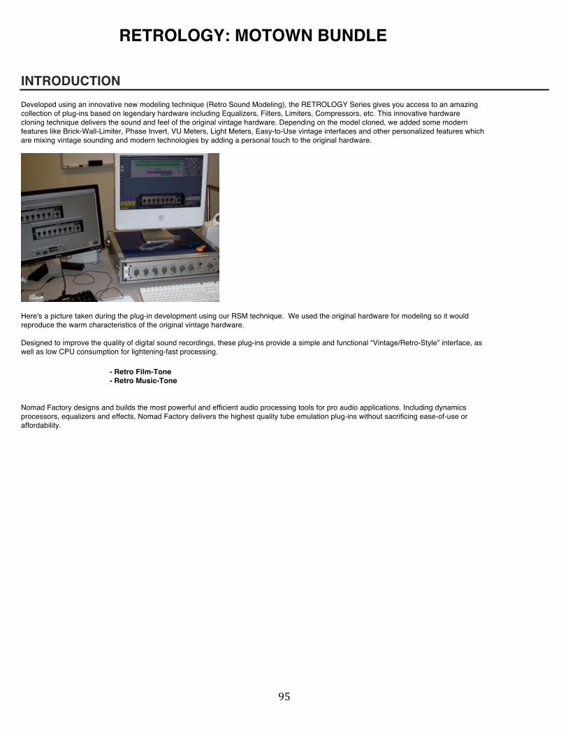
! *&!
RETROLOGY: MOTOWN BUNDLE
INTRODUCTION Developed using an innovative new modeling technique (Retro Sound Modeling), the RETROLOGY Series gives you access to an amazing collection of plug-ins based on legendary hardware including Equalizers, Filters, Limiters, Compressors, etc. This innovative hardware cloning technique delivers the sound and feel of the original vintage hardware. Depending on the model cloned, we added some modern features like Brick-Wall-Limiter, Phase Invert, VU Meters, Light Meters, Easy-to-Use vintage interfaces and other personalized features which are mixing vintage sounding and modern technologies by adding a personal touch to the original hardware.
Here's a picture taken during the plug-in development using our RSM technique. We used the original hardware for modeling so it would reproduce the warm characteristics of the original vintage hardware. Designed to improve the quality of digital sound recordings, these plug-ins provide a simple and functional “Vintage/Retro-Style” interface, as well as low CPU consumption for lightening-fast processing.
- Retro Film-Tone - Retro Music-Tone Nomad Factory designs and builds the most powerful and efficient audio processing tools for pro audio applications. Including dynamics processors, equalizers and effects, Nomad Factory delivers the highest quality tube emulation plug-ins without sacrificing ease-of-use or affordability.

! *'!
Retro Film-Tone
Like his brother, the Retro Film-Tone is a 7-band passive equalizer with fixed frequencies and Proportional Q emulation of the hardware version used exclusively by Motown engineers.
The Retro Film-Tone provides a close emulation of the original units, which introduces Proportional Q, where small boost/cuts have broad Q and greater boost/cuts have narrow Q.
7 Band-EQ: ± 8 dB: Default: 0 dB Each of these knobs controls the output level (dB) of each of the band-EQ filters. 80 Hz, 200 Hz, 500 Hz, 1250 Hz, 3200 Hz, 8000 Hz, 16000 Hz. Output: ± 8 dB: Default: 0 dB Sets the overall output level of the effect (dB). This control is useful to adjust the output level gain after its been reduced or boosted from applying equalization to the signal. Phase Switch: Normal, Inverted: Default: Normal Inverts the phase of the equalizer. Power: On or Off: Default: On With the switch in the 'On' position, the equalizer is activated, and the red LED above the switch is illuminated.
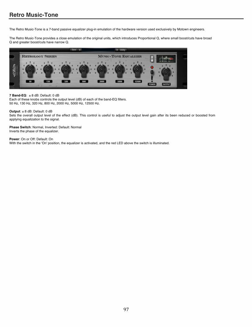
! *(!
Retro Music-Tone
The Retro Music-Tone is a 7-band passive equalizer plug-in emulation of the hardware version used exclusively by Motown engineers.
The Retro Music-Tone provides a close emulation of the original units, which introduces Proportional Q, where small boost/cuts have broad Q and greater boost/cuts have narrow Q.
7 Band-EQ: ± 8 dB: Default: 0 dB Each of these knobs controls the output level (dB) of each of the band-EQ filters. 50 Hz, 130 Hz, 320 Hz, 800 Hz, 2000 Hz, 5000 Hz, 12500 Hz. Output: ± 8 dB: Default: 0 dB Sets the overall output level of the effect (dB). This control is useful to adjust the output level gain after its been reduced or boosted from applying equalization to the signal. Phase Switch: Normal, Inverted: Default: Normal Inverts the phase of the equalizer. Power: On or Off: Default: On With the switch in the 'On' position, the equalizer is activated, and the red LED above the switch is illuminated.

! *)!
RETROLOGY: BRITISH BUNDLE
British MCL-2269 The British MLC-2269 is a simple and elegant Master Compressor Limiter (MCL). The British MCL-2269 is the perfect choice for a truly "British-Style" vintage sounding.
Input: ± 20 dB: Default: 0 dB Sets the overall input level of the MCL-2269 (dB). This control is useful to adjust the input level gain before applying compression to the signal. Output: ± 20 dB: Default: 0 dB Sets the overall output level of the MCL-2269 (dB). This control is useful to adjust the output level gain after its been reduced from applying compression to the signal. Vintage: On or Off: Default: Off With the switch in the 'On' position, the MCL-2269 recreates the harmonic distortion and noise level of the original modeled hardware processor, when activated, the red LED above the switch is illuminated. Power: On or Off: Default: On With the switch in the 'On' position, the MCL-2269 is activated, and the red LED above the switch is illuminated.

! **!
British MCL-2269 – Limiter Section: Limit: On or Off: Default: Off With the switch in the 'On' position, the Limiter section is activated, and the red LED above the switch is illuminated. Limit Level: +4 dB to +12 dB: Default: +12 dB Sets the threshold level of the Limiter section above which the device begins to limit the signal. The amount of reduced level is shown on the Limit Gain Reduction meter. Attack: Fast or Slow: Default: Fast The time, measured in milliseconds (ms), it takes for the limiter to reach its maximum level on the sound. - Fast = 0.1 ms - Slow = 1 ms Release: 100 ms, 200 ms, 800 ms, Auto; Default: Auto Controls how long (ms) it takes to release a signal from the limiter once it's dipped below your specified threshold. A long release time can be useful for adding sustain to a signal. - Auto: depending on the input signal 170 ms to 3000 ms. ! British MCL-2269 – Compressor Section Comp: On or Off: Default: On With the switch in the 'On' position, the Compressor section is activated, and the red LED above the switch is illuminated. Threshold: -20 dB to +10dB: Default: 0 dB Sets the decibel (dB) threshold to the level at which the compressor begins to work. If you set it to -10 dB for instance, any signal exceeding the Threshold level (-10 dB) are reduced in level, and the amount of compression is shown on the Comp Gain Reduction meter. Ratio: 1,5:1, 2:1, 3:1, 4:1, 6:1: Default: 3:1 dB This sets the amount of compression ratio, in dB, applied to a signal once it violates your pre-set threshold. A ratio of 4:1 will output 1 dB for every 4 dB of input signal that exceeds your targeted threshold. Release: 400 ms, 800 ms, 1500 ms, Auto; Default: 400 ms Controls how long (ms) it takes to release a signal from the compressor once it's dipped below your specified threshold. - Auto depending on the input signal 800 ms to 2500 ms. Comp Gain: 0 dB to +20 dB: Default: +4 dB Sets the overall output level of the compressor section (dB). This control is useful to adjust the output compressor gain after its been reduced from applying the compression to the signal, If the limiter is activated (On position), the Comp Gain will be applied before the Limiter section. Clicking on the Nomad Factory logo will display the back panel or about panel.

! "++!
British NEQ-1972 The British "Nomad-EQ" NEQ-1972 is a simple and elegant “British-Style” four-band equalizer with low-pass and high-pass filters. The NEQ-1972 provides ± 18 dB of gain and switchable High-Q settings.
Phase Switch: Normal, Inverted: Default: Normal Inverts the phase of the equalizer. HP Selector: This control determines the frequency of the high pass filter, 5 frequencies are available: 27, 47, 82, 150, 2270 Hz, when “Off” is selected, the High Pass filter is bypassed. LP Selector: This control determines the frequency of the Low Pass filter, 5 frequencies are available: 3.9, 5.6, 8.7, 12, 18 kHz, when “Off” is selected, the Low Pass filter is bypassed. Low Freq (Band 1): 33, 56, 100, 180, 330 Hz: Default: Off Selects the cut-off frequency for the EQ (Band 1) filter section. Low Freq (Band 1): Shelf/Peaking Switch: This switch determines the type of filter equalization (shelving or peaking). Lo-Mid Freq (Band 2): 220, 270, 330, 390, 470, 560, 680, 820, 1000, 1200 Hz: Default: Off Selects the cut-off frequency for the EQ (Band 2) filter section. Lo-Mid (Band 2): HiQ Switch: This controls the width of the Lo-Mid frequency curve from normal 'Broad' to HiQ 'Sharp' Hi-Mid Freq (Band 3): 1.5, 1.8, 2.2, 2.7, 3.3, 3.9, 4.7, 5.6, 8.2 kHz: Default: Off Selects the cut-off frequency for the EQ (Band 3) filter section. Hi-Mid (Band 3): HiQ Switch: This controls the width of the Hi-Mid frequency curve from normal 'Broad' to HiQ 'Sharp' High Freq (Band 4): 3.3, 4.7, 6.8, 10, 15 Hz: Default: Off Selects the cut-off frequency for the EQ (Band 4) filter section.
High Freq (Band 4): Shelf/Peaking Switch: This switch determines the type of filter equalization (shelving or peaking). Gain (Band 1 to Band 4): ± 18 dB: Default: 0 dB The Gain control is continuously variable with up to +18 dB of boost (full clockwise rotation) or -18 dB of cut (full counter-clockwise rotation). Power: On or Off: Default: On With the switch in the 'On' position, the equalizer is activated, and the red LED above the switch is illuminated. Output: ± 18 dB: Default: 0 dB Sets the overall output level of the effect (dB). This control is useful to adjust the output level gain after its been reduced or boosted from applying equalization to the signal. Vintage: On or Off: Default: Off

! "+"!
With the switch in the 'On' position, the NEQ-1081 recreates the harmonic distortion and noise level of the original modeled hardware processor, when activated, the red LED above the switch is illuminated. Clicking on the Nomad Factory logo will display the back panel or about panel.
!

! "+#!
RETROLOGY: PULSETEC EQs INTRODUCTION Developed using an innovative new modeling technique (Retro Sound Modeling), the RETROLOGY Series gives you access to an amazing collection of plug-ins based on legendary hardware including Equalizers, Filters, Limiters, Compressors, etc. This innovative hardware cloning technique delivers the sound and feel of the original vintage hardware. Depending on the model cloned, we added some modern features like Brick-Wall-Limiter, Phase Invert, VU Meters, Light Meters, Easy-to-Use vintage interfaces and other personalized features to mix vintage and modern technologies by adding a personal touch to the original hardware.
The PULSE-TEC EQs includes the legendary Pultec Mid-Range Equalizer MEQ-5 and the well-known Pultec Program Equalizer EQP-1A into a single high quality plug-In, the PULSE-TEC EQs. The PULSE-TEC EQs sections can be enabled or disabled individually or used simultaneously for full range analog equalization. We added an analog Pre-Amp section, which adds Input Level and Output Level controls as well as a simple 'Clipper' limiter at the master output section.
- The PULSE-TEC MEQ-5 Mid-Range Equalizer section is designed to add Body and Presence to your recorded tracks. Highlight or Subdue a vocalist where the vocal is already mixed with the orchestra, improve the quality of voices by altering their fundamental and overtone relationships.
- The PULSE-TEC EQP-1A Equalizer section will add a wide range of equalization. This makes it possible to boost the very low or very high frequency notes of the orchestra without 'muddying up' the middle register instruments. Continuously variable controls permit changing the amount of the equalization or sustained tones without step in level or noise.
Nomad Factory designs and builds the most powerful and efficient audio processing tools for pro audio applications. Including dynamics processors, equalizers and effects, Nomad Factory delivers the highest quality tube emulation plug-ins without sacrificing ease-of-use or affordability.

! "+$!
PULSE-TEC MID-RANGE EQUALIZER MEQ-5

! "+%!
PULSE-TEC PROGRAM EQUALIZER EQP-1A
NOTE on EQP-1A & MEQ-5: Vintage Button EQP-1A & MEQ-5: On or Off: Default: Off With the switch in the 'On' position, the 'VINTAGE' button recreates the harmonic distortion and noise level of the original modeled hardware processor, when activated, the red LED above the switch is illuminated.

! "+&!
STEREO PRE-AMPLIFIER PRE-2S
The Stereo Pre-Amplifier PRE-2S is a simple and elegant Master Amplifier.
Input: ± 18 dB: Default: 0 dB Sets the overall input level of the PULSE-TEC EQs (dB). This control is useful to adjust the input level gain before applying equalization to the signal. Output: ± 18 dB: Default: 0 dB Sets the overall output level of the PULSE-TEC EQs (dB). This control is useful to adjust the output level gain after its been reduced or boosted from applying equalization to the signal. Clipper: On or Off: With the switch in the 'On' position, the 'BrickWall' Limiter section is activated, and the blue LED above the switch is illuminated. Power: On or Off: Default: On With the switch in the 'On' position, the MCL-2269 is activated, and the red LED above the switch is illuminated.

! "+'!
RETROLOGY: ALL-TECH
INTRODUCTION This classic piece of hardware has been cloned and offered in a sleek, simple plug-in to add that classic EQ effect on your tracks. This innovative hardware cloning technique delivers the sound and feel of the original vintage hardware.
With its 5 knobs, the ALL-TECH interface is bare bones, but the sound achieved with some minor tweaking is amazing. For those who are familiar with the original hardware, this digital recreation is no small feat!
Doubling up as a shelving and peak EQ depending on the settings chosen, the ALL-TECH can attenuate and boost by increments of 2 db in LO Frequency and High Frequency spectrums.
Add this EQ to get that classic vintage sound for your mix!

! "+(!
ALL-TECH 9063B EQ
LO Freq Selector: Knob has 3 selections. Select low frequency 40Hz or 100Hz as well as “OFF” (Bypass).
LO FREQ: Attenuate (by turning knob to left) and boost (by turning to the right) in increments of 2 dB. 0 to 12 dB turning to the right (Equalize) and 0 to 16 dB to the left (Attenuate).
Shelving EQ in the Low Frequencies.
Volume: Master level. – 18 to + 18.
HI FREQ: Attenuate (by turning knob to left) and boost (by turning to the right) in increments of 2 dB. 0 to 12 dB turning to the right (Equalize) and 0 to 16 dB to the left (Attenuate).
Shelving EQ when attenuating (Cut).
When Boosting (Equalize), it takes Peak EQ characteristics. As Equalization is increased (boost), the Q (bandwidth) narrows consistently around the “HI FREQ SELECTOR” setting chosen.
HI Freq Selector: Knob has 4 selections. Select high frequency: 3kHz, 5kHz, 10kHz, or 15kHz.

! "+)!
ROCK AMP LEGENDS
INTRODUCTION
Congratulations on choosing Nomad Factoryʼs guitar amp plug-in “Rock Amp Legends by Jimmy Crespo”. We are sure you will enjoy the new sound in guitar amp simulation. Nomad Factory designs and builds the most powerful and efficient audio processing tools for pro audio applications. Including dynamics processors, equalizers and effects, Nomad Factory delivers the highest quality tube emulation plug-ins without sacrificing ease-of-use or affordability.
This User Guide describes the controls and functions of the Rock Amp Legends guitar amp simulator plug-in.
Features
* High quality processing using double precision floating point * Up to 48kHz sample rates supported * Automate any control via RTAS, VST, and HTDM host applications * Set of factory presets * Authorize Disk (Receive an authorization Challenge/Response)
Getting Started:
When inserting the Rock Amp Legends plug-in on a channel, choose “Mono to Stereo” in order to hear the effects in stereo. If you choose “Mono”, the stereo effects will not be audible.
Note to Cubase Users: Since Cubase insert strips are Mono and cannot be used as Mono to Stereo, Cubase users should convert a mono file to stereo in order to use the Stereo FX on the insert channel.
After launching the plug-in, try the “Factory” presets. These 82 presets provide a good starting point to create and save your own additional presets. This way you can capture, and easily recall, your signature guitar sound.
Also, each knob (pot) on the amp has a global default setting (not related to a particular preset). To reset a knob to the default position on a Mac, press Apple + click on the knob; on a PC, press Alt + click on the knob.

! "+*!
FRONT PANEL
Power:
Turns the amp plug-in on and off
FX:
Displays the effects panel (FX Rack)
A/B:
This control switches between the A and B banks of amp simulations. This switch basically provides two different sounds for each amp simulation in the menu below.
Amp Simulations Menu:
This menu is visible below the Power, FX and A/B switches. It appears as a small box displaying the name of the currently selected amp. Clicking this box displays a drop down menu of all amp choices, plus a Bypass option. Clicking on an amp name selects that amp simulation. Also, for each amp simulation two sounds are available via the A/B switch.
Amp Simulations: - Classic Lead 4x12 A - Classic Lead 4x12 B - Classic Lead 4x12 C - Modern Lead 4x12 A - Modern Lead 4x12 B - Modern Lead 4x12 C - Combo A 1x12 - Combo B 2x12 - Combo C 2x12 - Tweed A 1x12 - Tweed B 2x12 - Tweed C 2x12 - Super Lead 4x12 A - Super Lead 4x1 - Super Lead 4x12 C - Rectified Lead 4x12 A - Rectified Lead 4x12 B - Rectified Lead 4x12 C - BYPASS
Master:
Controls the overall output level of the amp
Presence:
Controls the clarity of the amp tone. Adjust the Presence in conjunction with the Treble for the desired high-end sound.
Treble:
Adjusts the high frequencies in the amp tone

! ""+!
Middle:
Adjusts the middle frequencies in the amp tone
Bass:
Adjusts the low frequencies in the amp tone
Reverb:
Controls the amount of reverb added to the signal; increase the reverb to simulate a larger “room size”
Drive:
Controls the gain added by the “preamp” section of the amp; overdrive
Input:
Switches the instrument cable between High and Low input level jacks; this effect gives a slight input boost; the effect is more noticeable in conjunction with the lower Drive settings (<50)

! """!
FX RACK
To turn on each effect, click the “on/off” toggle switch in the corresponding effect section. The following sections describe each effect section individually.
Stereo Imager:
Width Meter:
Graphically displays the spread of the stereo image.
Width:
Controls the audible width of the stereo image. Turning the knob to the right widens the stereo image; turning the knob to the left brings the image back toward the center of the stereo field. To enable the effect, click the “on/off” toggle switch.
Close: Closes the FX Rack and returns to the Front Pane
Equalizer:
Low Gain:
Controls the gain of the low frequencies; the specific (center) frequency may be selected using the knob to the right (50-600Hz)
Bandwidth:
Adjusts the width of the frequency band around the center frequency; increasing the Bandwidth widens the range of frequencies adjusted by the Low Gain control; decreasing the Bandwidth creates a narrow range of frequencies adjusted by the Low Gain control
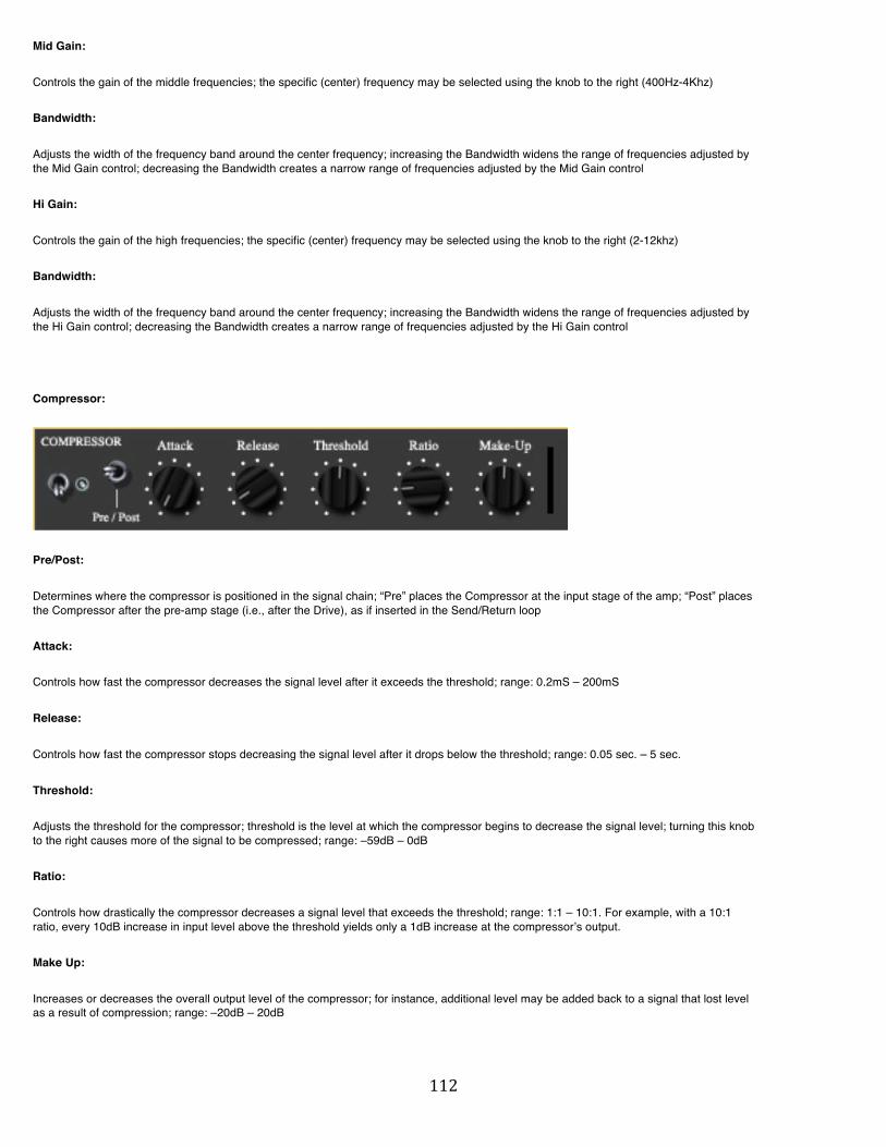
! ""#!
Mid Gain:
Controls the gain of the middle frequencies; the specific (center) frequency may be selected using the knob to the right (400Hz-4Khz)
Bandwidth:
Adjusts the width of the frequency band around the center frequency; increasing the Bandwidth widens the range of frequencies adjusted by the Mid Gain control; decreasing the Bandwidth creates a narrow range of frequencies adjusted by the Mid Gain control
Hi Gain:
Controls the gain of the high frequencies; the specific (center) frequency may be selected using the knob to the right (2-12khz)
Bandwidth:
Adjusts the width of the frequency band around the center frequency; increasing the Bandwidth widens the range of frequencies adjusted by the Hi Gain control; decreasing the Bandwidth creates a narrow range of frequencies adjusted by the Hi Gain control
Compressor:
Pre/Post:
Determines where the compressor is positioned in the signal chain; “Pre” places the Compressor at the input stage of the amp; “Post” places the Compressor after the pre-amp stage (i.e., after the Drive), as if inserted in the Send/Return loop
Attack:
Controls how fast the compressor decreases the signal level after it exceeds the threshold; range: 0.2mS – 200mS
Release:
Controls how fast the compressor stops decreasing the signal level after it drops below the threshold; range: 0.05 sec. – 5 sec.
Threshold:
Adjusts the threshold for the compressor; threshold is the level at which the compressor begins to decrease the signal level; turning this knob to the right causes more of the signal to be compressed; range: –59dB – 0dB
Ratio:
Controls how drastically the compressor decreases a signal level that exceeds the threshold; range: 1:1 – 10:1. For example, with a 10:1 ratio, every 10dB increase in input level above the threshold yields only a 1dB increase at the compressorʼs output.
Make Up:
Increases or decreases the overall output level of the compressor; for instance, additional level may be added back to a signal that lost level as a result of compression; range: –20dB – 20dB

! ""$!
Gain Reduction Meter:
Displays the reduction in signal level as a result of compression; range: 0db – 30dB
Noise Gate:
Pre/Post:
Determines where the noise gate is positioned in the signal chain. “Pre” places the Noise Gate at the input stage of the amp; “Post” places the Noise Gate after the pre-amp stage (i.e., after the Drive), as if inserted in the Send/Return loop.
Attack:
Controls how fast the gate opens after a signal exceeds the threshold. Short attack settings avoid cutting off the beginning of transient signals. Range: 10 microSeconds – 200 milliSeconds
Release:
Controls how fast the gate closes after the signal drops below the threshold and the Hold time expires; range: 5ms – 4 sec.
Threshold:
Adjusts the threshold for the noise gate. Threshold is the level above which a signal opens the gate. If signals do not have more level than the threshold, then the gate stays closed. Turning this knob to the right raises the threshold. Range: -90dBfs - ∞
Hold:
Determines how long the gate remains open after the signal level drops below the threshold and before the Release begins. Range: 2mS – 2 sec.
Range:
Controls the output level of a signal whose input level is below the threshold (i.e., the output level while the gate is closed). Turning the knob to the right decreases the output level of a signal below the threshold. Range: 0dB to –90dB
Noise Gate Meter:
Displays the status of the gate. Green = gate is opened; red = gate is closed; yellow = gate is either opening or closing.

! ""%!
Tremolo:
Center/Pan:
Toggles between a standard tremolo effect (in the center of the stereo field) and an auto-pan effect
Speed:
Controls how fast the effect cycles through level changes. Turning the knob to the right creates faster cycle speed.
Depth:
Controls the variation between high levels and low levels in tremolo cycles
Modulator:
Chorus/Phaser:
Toggles between a chorus effect and a phaser effect
Speed:
Controls how fast the effect cycles through level changes. Turning the knob to the right creates faster cycle speed.
Depth:
Controls the variation between high levels and low levels in effect cycles
Mix:
Adjusts the proportion of dry signal to wet (effect) signal

! ""&!
Delay:
Time:
Controls the amount of time between the original signal and the delayed signal
Feedback:
Determines how much the delayed signal is repeated.
Width:
Controls the amount of “ping-pong” delay effect. The individual repeats alternate between the Left and Right channels. Turning the knob to the right increases the separation between the alternating delays.
Mix:
Adjusts the proportion of dry signal to wet (delayed) signal.

! ""'!
MAGNETIC Reel-to-Reel Audio Tape Warmer
Nomad Factory introduces MAGNETIC, a Reel-to-Reel Audio Tape Warming effect that gives your tracks the elusive vintage tape sound which your ears crave. This effect can inject sterile audio with the warmth and character of classic tube circuitry and analog tape saturation.
The plug-in features pure analog reel-to-reel tape speeds, tape/tube saturation and tape color effects, as well as a dedicated vintage style EQ and a built in Boost mastering section. The result is a creamy, warm sound that can only be achieved by MAGNETIC.
!!!!!!!!!!!
! ""(!
MAGNETIC CONTROLS Reel Speed: This knob controls the speed of the virtual tape machine. Higher speeds give you more studio-quality fidelity; lower speeds sound more like a cassette tape. The DASH setting gives you the highest-fidelity of digital audio tape predominately used in the 80’s and 90’s. Saturation: This knob gives different levels of tube and/or tape saturation effects. Recreates the warmth and character of classic tube circuitry and analog tape saturation. Tape Color: This knob provides the highly sought-after sound of Natural, Vintage and Modern Tape Compression. Lows: This Knob controls the amount of low frequency equalization. Select the boost/cut frequency range with the Body, Warm, and Lush Settings. Highs: This knob controls the amount of high frequency equalization. Select the boost/cut frequency range with the Detail, Focus and Brilliance Settings. Boost: This button switches on/off the built-in Mastering Limiter section. This incorporates multiple stages of limiting and a look-ahead brickwall limiter to deliver first-class peak reduction. Adjust the Gain and Ceiling Knobs to achieve High-Resolution Limiting. Gain: This knob sets the threshold for the incoming signal. Higher settings result in a louder sound. Ceiling: This knob sets the brickwall output level so that it limits all peaks above the number it is set to. V/U Meter: Shows the amount of limiting taking place when the Boost is engaged. Power: Bypasses the entire unit. Reset Button: Unlike the rest of Nomad Factory plug-ins, Magnetic has a Reset button instead of a Utility button at the top of the GUI. The Reset Button recalls the knob settings of the currently loaded preset. So if you load a preset and make changes to it, the Reset Button will bring you back to the original settings of the loaded preset.