next generation firewall - forcepoint · forcepoint next generation firewall 4u hardware guide 5...
TRANSCRIPT
Next GenerationFirewallHardware GuideModel 6205Revision B
Forcepoint Next Generation Firewall 4U Hardware Guide
2
Contents
• Introduction on page 2• Find product documentation on page 2• Model 6205 features on page 3• Supported interface modules on page 6• Precautions on page 12• Install the appliance on page 14• Maintenance on page 23
IntroductionThank you for choosing a Forcepoint™ Next Generation Firewall (Forcepoint NGFW) appliance.
Familiarize yourself with the appliance ports and indicators and learn how to install the appliance safely.
Find product documentationOn the Forcepoint support website, you can find information about a released product, including productdocumentation, technical articles, and more.
You can get additional information and support for your product on the Forcepoint support website athttps://support.forcepoint.com. There, you can access product documentation, Knowledge Base articles,downloads, cases, and contact information.
Forcepoint Next Generation Firewall 4U Hardware Guide
3
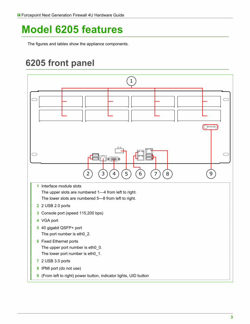
Model 6205 featuresThe figures and tables show the appliance components.
6205 front panel
42 6
1
93 5 7 8
1 Interface module slotsThe upper slots are numbered 1—4 from left to right.The lower slots are numbered 5—8 from left to right.
2 2 USB 2.0 ports
3 Console port (speed 115,200 bps)
4 VGA port
5 40 gigabit QSFP+ portThe port number is eth0_2.
6 Fixed Ethernet portsThe upper port number is eth0_0.The lower port number is eth0_1.
7 2 USB 3.0 ports
8 IPMI port (do not use)
9 (From left to right) power button, indicator lights, UID button
Forcepoint Next Generation Firewall 4U Hardware Guide
4
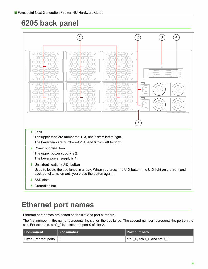
6205 back panel
31 2 4
5
1 FansThe upper fans are numbered 1, 3, and 5 from left to right.The lower fans are numbered 2, 4, and 6 from left to right.
2 Power supplies 1—2The upper power supply is 2.The lower power supply is 1.
3 Unit identification (UID) buttonUsed to locate the appliance in a rack. When you press the UID button, the UID light on the front andback panel turns on until you press the button again.
4 SSD slots
5 Grounding nut
Ethernet port namesEthernet port names are based on the slot and port numbers.
The first number in the name represents the slot on the appliance. The second number represents the port on theslot. For example, eth2_0 is located on port 0 of slot 2.
Component Slot number Port numbers
Fixed Ethernet ports 0 eth0_0, eth0_1, and eth0_2.
Forcepoint Next Generation Firewall 4U Hardware Guide
5
Component Slot number Port numbers
Interface moduleports
1–8. Slots 1–4 are on the upper row, andslots 5–8 are on the lower row.
The port numbers start from 0 and increasefrom left to right. For example, the portfarthest to the left in slot 1 is eth1_0.
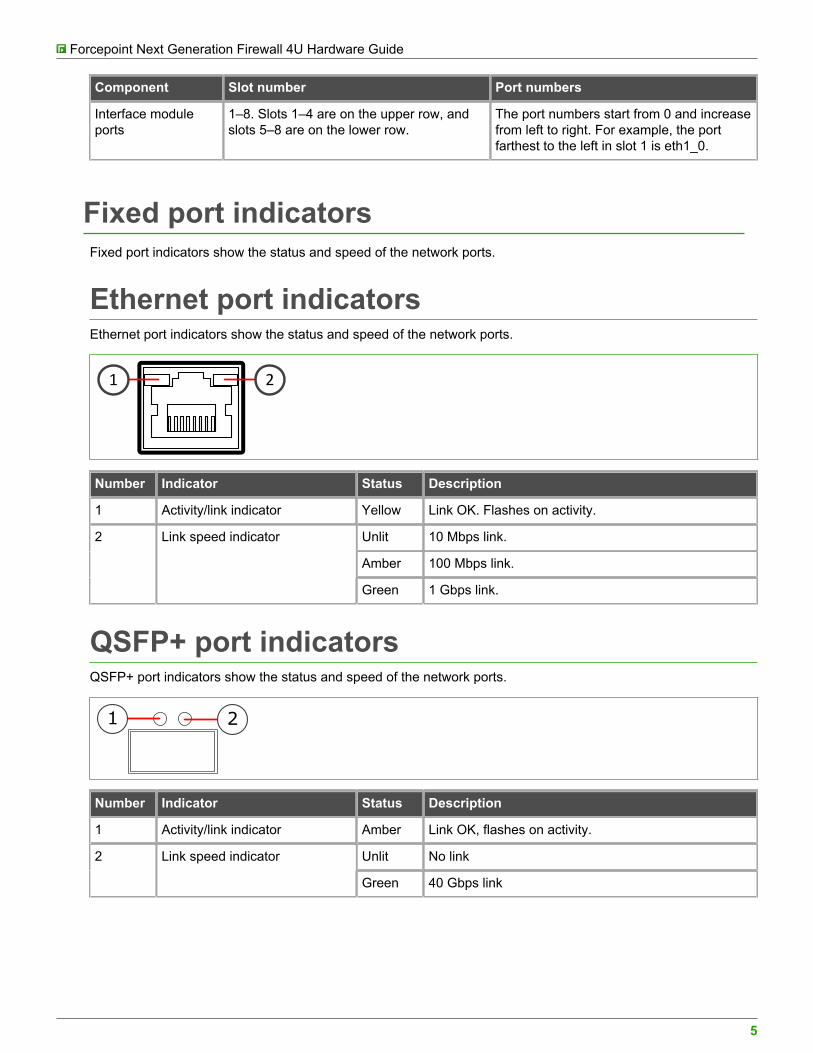
Fixed port indicatorsFixed port indicators show the status and speed of the network ports.
Ethernet port indicatorsEthernet port indicators show the status and speed of the network ports.
1 2
Number Indicator Status Description
1 Activity/link indicator Yellow Link OK. Flashes on activity.
Unlit 10 Mbps link.
Amber 100 Mbps link.
2 Link speed indicator
Green 1 Gbps link.
QSFP+ port indicatorsQSFP+ port indicators show the status and speed of the network ports.
1 2
Number Indicator Status Description
1 Activity/link indicator Amber Link OK, flashes on activity.
Unlit No link2 Link speed indicator
Green 40 Gbps link
Forcepoint Next Generation Firewall 4U Hardware Guide
6
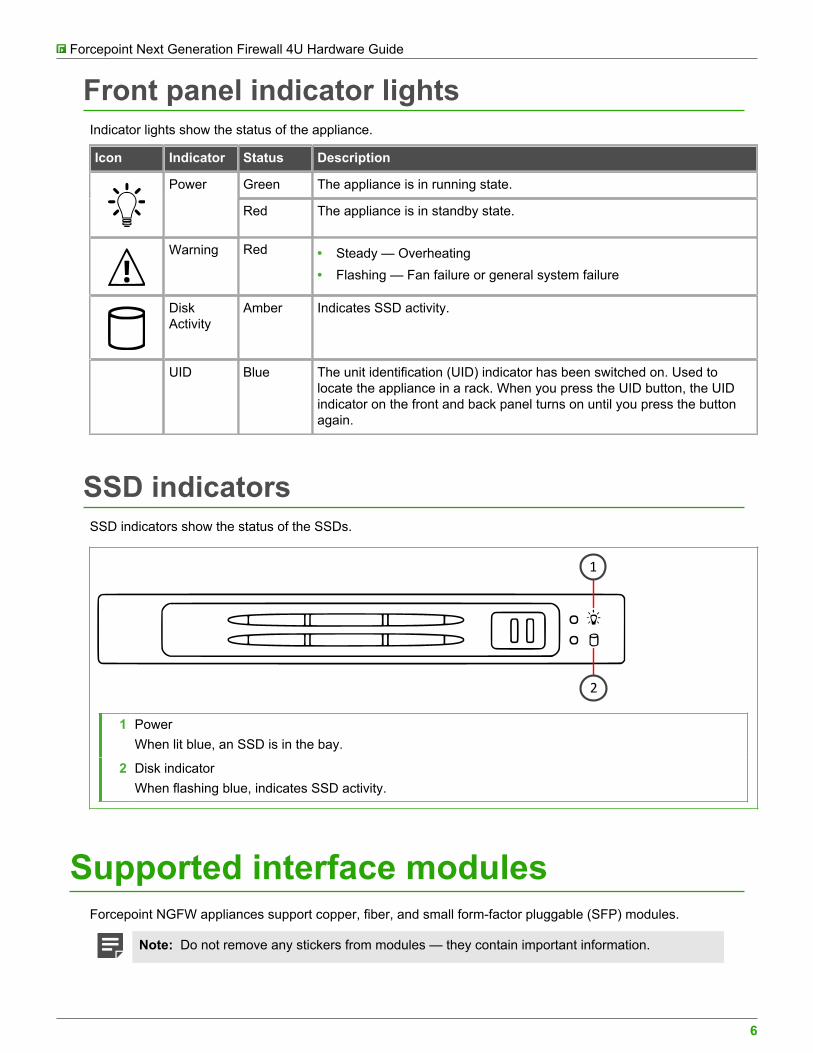
Front panel indicator lightsIndicator lights show the status of the appliance.
Icon Indicator Status Description
Green The appliance is in running state.Power
Red The appliance is in standby state.
Warning Red • Steady — Overheating• Flashing — Fan failure or general system failure
DiskActivity
Amber Indicates SSD activity.
UID Blue The unit identification (UID) indicator has been switched on. Used tolocate the appliance in a rack. When you press the UID button, the UIDindicator on the front and back panel turns on until you press the buttonagain.
SSD indicatorsSSD indicators show the status of the SSDs.
1
2
1 PowerWhen lit blue, an SSD is in the bay.
2 Disk indicatorWhen flashing blue, indicates SSD activity.
Supported interface modulesForcepoint NGFW appliances support copper, fiber, and small form-factor pluggable (SFP) modules.
Note: Do not remove any stickers from modules — they contain important information.
Forcepoint Next Generation Firewall 4U Hardware Guide
7
For a list of all available interface modules and compatibility information, see Knowledge Base article 10245.
Table 1: Copper modules
Module Identifier
2 port 10 gigabit Ethernet RJ45 module MO102
4 port gigabit Ethernet bypass RJ45 module MOG4B
8 port gigabit Ethernet RJ45 module MOG8
Table 2: Fiber modules
Module Identifier
2 port 10 gigabit Ethernet short reach bypass module MO10S2B
2 port 10 gigabit Ethernet long reach bypass module MO10L2B
Table 3: SFP modules
Module Identifier
2 port 10 gigabit Ethernet SFP+ module MO10F2
2 port 40 gigabit Ethernet QSFP module MO40F2
4 port gigabit Ethernet SFP module MOGF4
4 port 10 gigabit Ethernet SFP+ module revision 2 MOE10F4
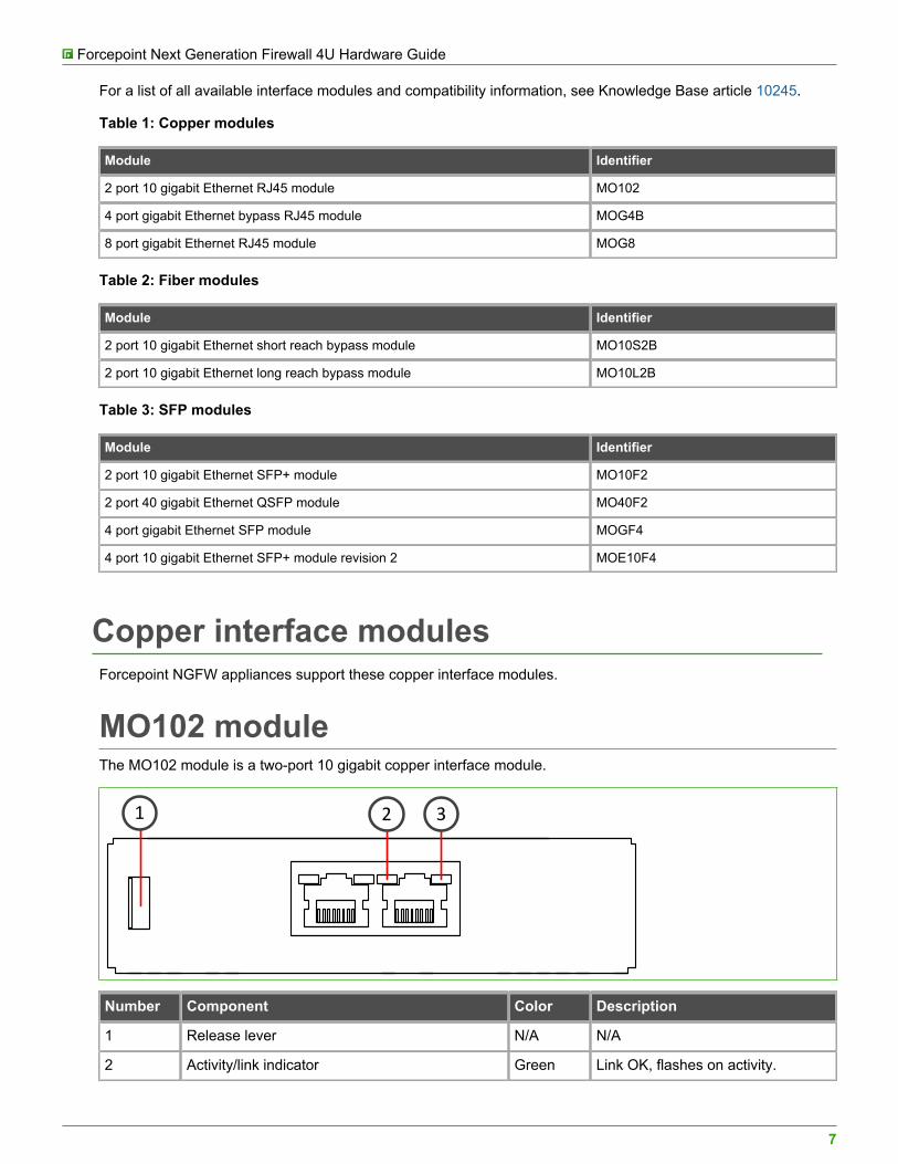
Copper interface modulesForcepoint NGFW appliances support these copper interface modules.
MO102 moduleThe MO102 module is a two-port 10 gigabit copper interface module.
2 31
Number Component Color Description
1 Release lever N/A N/A
2 Activity/link indicator Green Link OK, flashes on activity.
Forcepoint Next Generation Firewall 4U Hardware Guide
8
Number Component Color Description
Yellow 1 Gbps link.3 Link speed indicator
Green 10 Gbps link.
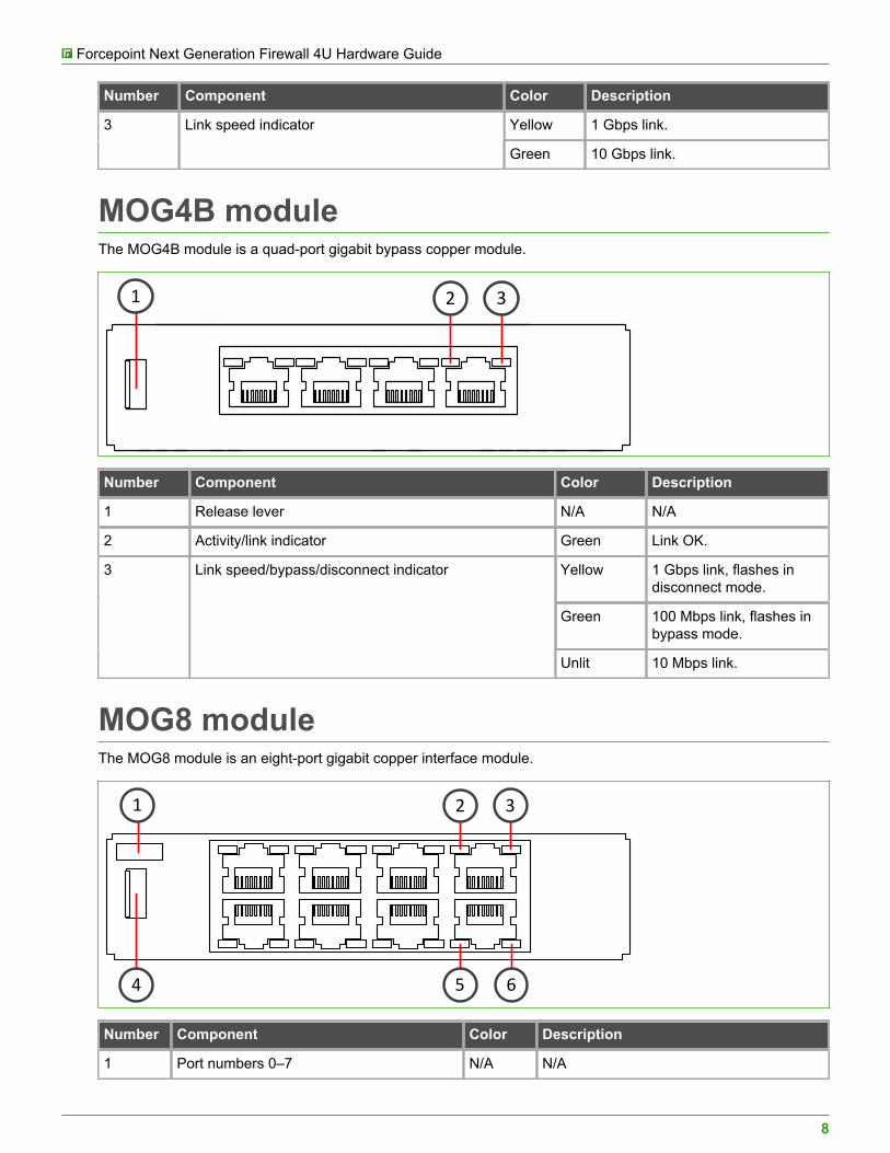
MOG4B moduleThe MOG4B module is a quad-port gigabit bypass copper module.
2 31
Number Component Color Description
1 Release lever N/A N/A
2 Activity/link indicator Green Link OK.
Yellow 1 Gbps link, flashes indisconnect mode.
Green 100 Mbps link, flashes inbypass mode.
3 Link speed/bypass/disconnect indicator
Unlit 10 Mbps link.
MOG8 moduleThe MOG8 module is an eight-port gigabit copper interface module.
2 31
5 64
Number Component Color Description
1 Port numbers 0–7 N/A N/A
Forcepoint Next Generation Firewall 4U Hardware Guide
9
Number Component Color Description
2, 5 Activity/link indicator Green Link OK, flashes on activity.
Yellow 1 Gbps link.
Green 100 Mbps link.
3, 6 Link speed indicator
Unlit 10 Mbps link.
4 Release lever N/A N/A
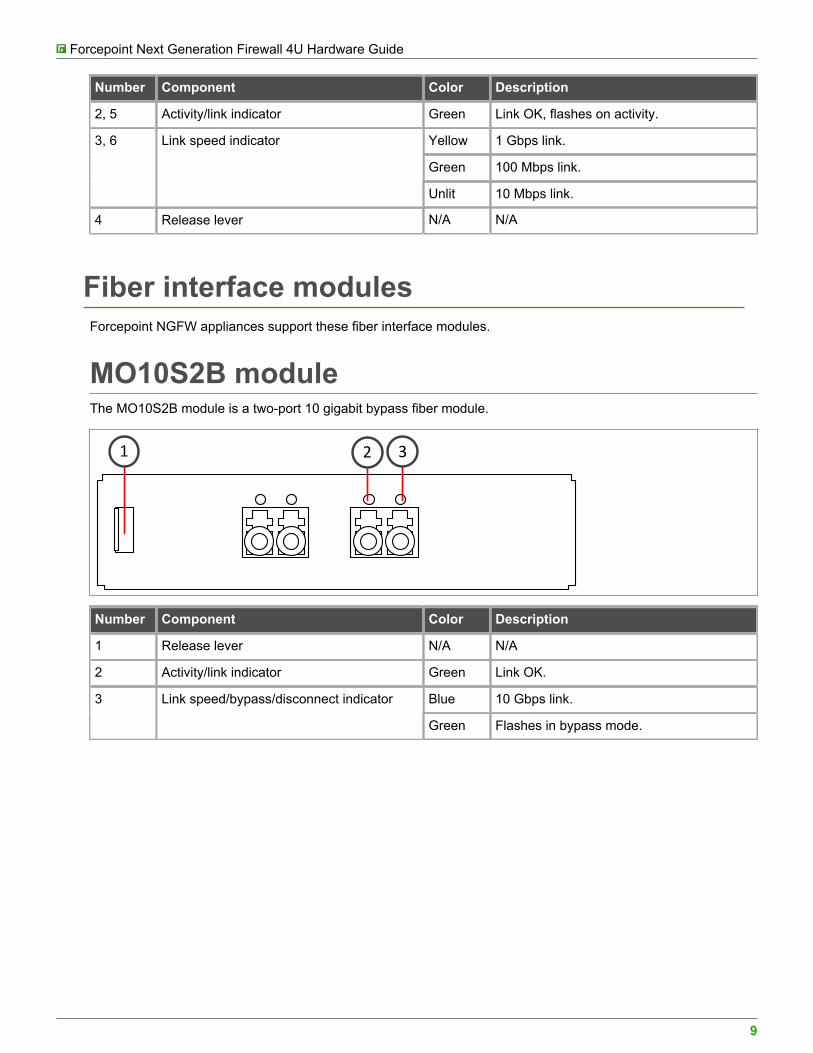
Fiber interface modulesForcepoint NGFW appliances support these fiber interface modules.
MO10S2B moduleThe MO10S2B module is a two-port 10 gigabit bypass fiber module.
2 31
Number Component Color Description
1 Release lever N/A N/A
2 Activity/link indicator Green Link OK.
Blue 10 Gbps link.3 Link speed/bypass/disconnect indicator
Green Flashes in bypass mode.
Forcepoint Next Generation Firewall 4U Hardware Guide
10
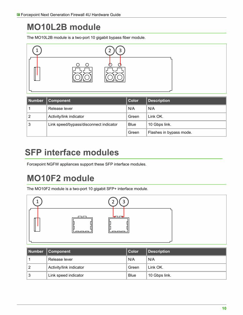
MO10L2B moduleThe MO10L2B module is a two-port 10 gigabit bypass fiber module.
2 31
Number Component Color Description
1 Release lever N/A N/A
2 Activity/link indicator Green Link OK.
Blue 10 Gbps link.3 Link speed/bypass/disconnect indicator
Green Flashes in bypass mode.
SFP interface modulesForcepoint NGFW appliances support these SFP interface modules.
MO10F2 moduleThe MO10F2 module is a two-port 10 gigabit SFP+ interface module.
2 31
Number Component Color Description
1 Release lever N/A N/A
2 Activity/link indicator Green Link OK.
3 Link speed indicator Blue 10 Gbps link.
Forcepoint Next Generation Firewall 4U Hardware Guide
11
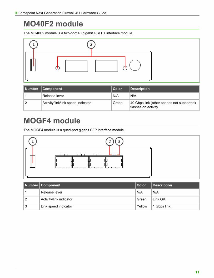
MO40F2 moduleThe MO40F2 module is a two-port 40 gigabit QSFP+ interface module.
1 2
Number Component Color Description
1 Release lever N/A N/A
2 Activity/link/link speed indicator Green 40 Gbps link (other speeds not supported),flashes on activity.
MOGF4 moduleThe MOGF4 module is a quad-port gigabit SFP interface module.
2 31
Number Component Color Description
1 Release lever N/A N/A
2 Activity/link indicator Green Link OK.
3 Link speed indicator Yellow 1 Gbps link.
Forcepoint Next Generation Firewall 4U Hardware Guide
12
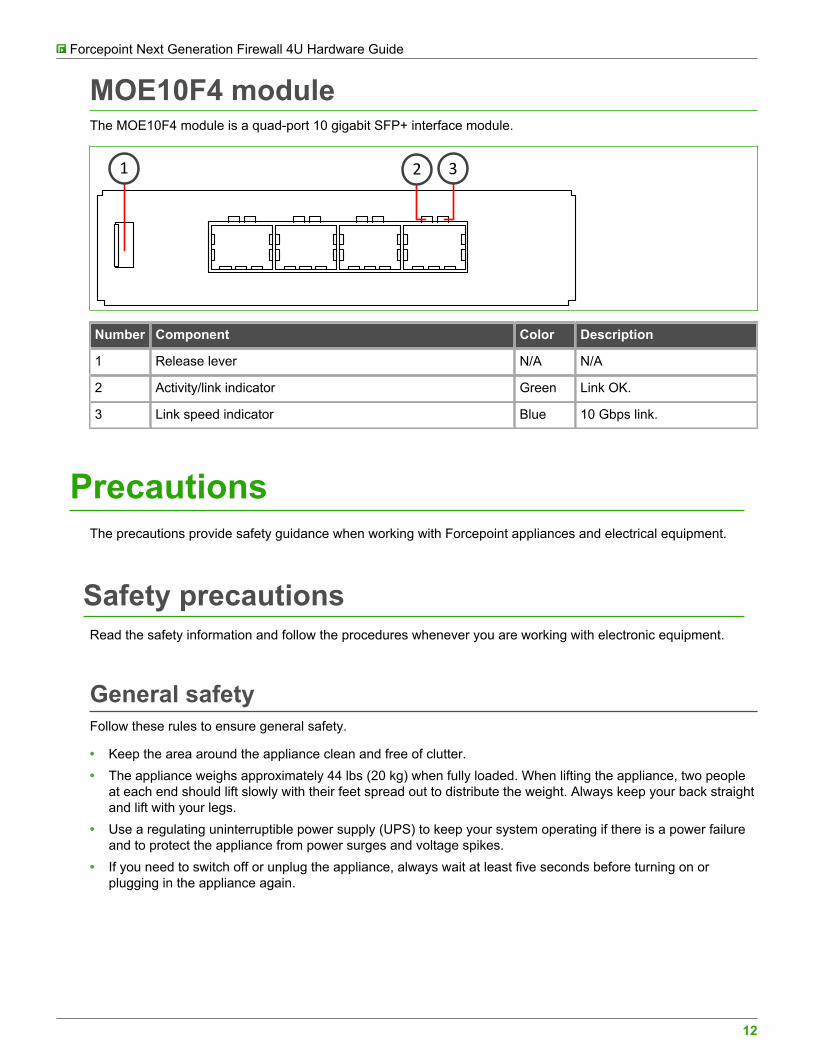
MOE10F4 moduleThe MOE10F4 module is a quad-port 10 gigabit SFP+ interface module.
2 31
Number Component Color Description
1 Release lever N/A N/A
2 Activity/link indicator Green Link OK.
3 Link speed indicator Blue 10 Gbps link.
PrecautionsThe precautions provide safety guidance when working with Forcepoint appliances and electrical equipment.
Safety precautionsRead the safety information and follow the procedures whenever you are working with electronic equipment.
General safetyFollow these rules to ensure general safety.
• Keep the area around the appliance clean and free of clutter.• The appliance weighs approximately 44 lbs (20 kg) when fully loaded. When lifting the appliance, two people
at each end should lift slowly with their feet spread out to distribute the weight. Always keep your back straightand lift with your legs.
• Use a regulating uninterruptible power supply (UPS) to keep your system operating if there is a power failureand to protect the appliance from power surges and voltage spikes.
• If you need to switch off or unplug the appliance, always wait at least five seconds before turning on orplugging in the appliance again.
Forcepoint Next Generation Firewall 4U Hardware Guide
13
Operating precautions• Do not open the power supply casing. Only the manufacturer's qualified technician can access and service
power supplies.• Keep the cover in place when the appliance is on to ensure proper cooling. Failure to adhere to this guidance
could void your warranty.
Additional safety information can be provided upon request.
Electrical safety precautionsFollow basic electrical safety precautions to protect yourself from harm and the appliance from damage.
• Know the locations of the power on/off button and the emergency turn-off switch, disconnection switch, orelectrical outlet for the room. If an electrical accident occurs, you can quickly turn off power to the system.
• When working with high-voltage components, do not work alone.• Turn off the system and disconnect the power before removing or installing system components.• When working with electrical equipment that is turned on, use only one hand. This is to avoid making a
complete circuit, which causes an electric shock. Use extreme caution when using metal tools, which caneasily damage any electrical components or circuit boards the tools come into contact with.
• Do not use mats designed to decrease electrostatic discharge as protection from electric shock. Instead, userubber mats that have been designed as electrical insulators.
• The power supply cable must include a grounding plug and must be plugged into a grounded electrical outlet.
Power supply safety precautionsDepending on the type of power supply that your Forcepoint NGFW appliance uses, different safety precautionsand installation guidelines apply.
Note: If the appliance has two power supplies, we recommend that you use both power suppliesfor redundancy.
AC power suppliesThe appliance power inlet is the disconnect device on the appliance.
DC power supplies• The appliance must be used in a restricted access location and users must be well trained to operate it.• The outlet for the appliance must be installed near the appliance and be easily accessible.• We recommend using a 30A fuse (slow) and a power switch between the appliance and the main power
source.• The appliance must be protected against electric shock and must have, at minimum, a 12 AWG wire provided
for the DC power supply.
Forcepoint Next Generation Firewall 4U Hardware Guide
14
• The case of the appliance must be grounded using the power connector pin or the grounding nut. Werecommend using both grounding methods.
• The mains supply plug on the power supply cable is the disconnect device on the appliance. To disconnectthe appliance, you must first disconnect the mains, then disconnect the ground.
Install the appliancePrepare and install the appliance in your network.
Before you begin• Install a Security Management Center (SMC) on a separate server.• Configure the NGFW Engine element (Firewall, IPS, or Layer 2 Firewall) in the Management Client,
and save the initial configuration.
Note: For additional information on SMC installation and initial configuration, see theForcepoint Next Generation Firewall Installation Guide.
• Inspect the appliance, the delivery box, and all components included in the shipment.
Note: Do not use damaged appliances or components.
Rack-mount the applianceThe rack-mounting procedure varies depending on the type of rack unit. If needed, see the documentation foryour rack unit.
Important: Read the safety precautions before you rack-mount the appliance. Do not install theappliance upside down.
Preparing for rack-mountingThe rack-mounting kit includes the mounting screws and the rail assemblies or rack-mounting brackets to installthe system into the rack.
Determine the placement of each component in the rack.
• Install the heaviest components on the bottom of the rack first. Install components from the bottom to the top.• The appliance must be connected to a grounded power outlet.• Use a UPS to protect the appliance from power surges and voltage spikes, and to keep your system operating
if there is a power failure.• To maintain proper cooling, always keep the front door of the rack and all panels and components on the
appliances closed when not servicing.
Forcepoint Next Generation Firewall 4U Hardware Guide
15
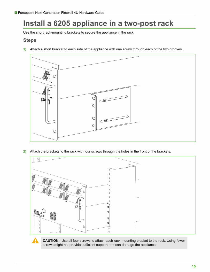
Install a 6205 appliance in a two-post rackUse the short rack-mounting brackets to secure the appliance in the rack.
Steps
1) Attach a short bracket to each side of the appliance with one screw through each of the two grooves.
2) Attach the brackets to the rack with four screws through the holes in the front of the brackets.
CAUTION: Use all four screws to attach each rack-mounting bracket to the rack. Using fewerscrews might not provide sufficient support and can damage the appliance.
Forcepoint Next Generation Firewall 4U Hardware Guide
16
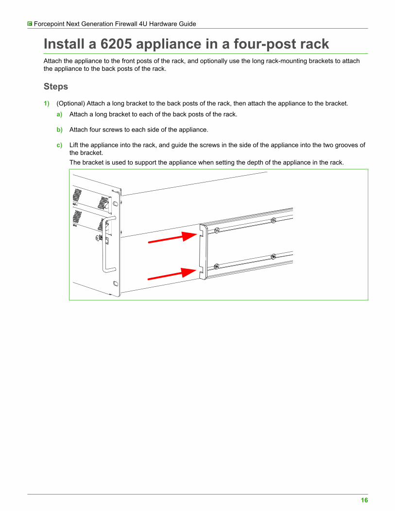
Install a 6205 appliance in a four-post rackAttach the appliance to the front posts of the rack, and optionally use the long rack-mounting brackets to attachthe appliance to the back posts of the rack.
Steps
1) (Optional) Attach a long bracket to the back posts of the rack, then attach the appliance to the bracket.
a) Attach a long bracket to each of the back posts of the rack.
b) Attach four screws to each side of the appliance.
c) Lift the appliance into the rack, and guide the screws in the side of the appliance into the two grooves ofthe bracket.The bracket is used to support the appliance when setting the depth of the appliance in the rack.
Forcepoint Next Generation Firewall 4U Hardware Guide
17
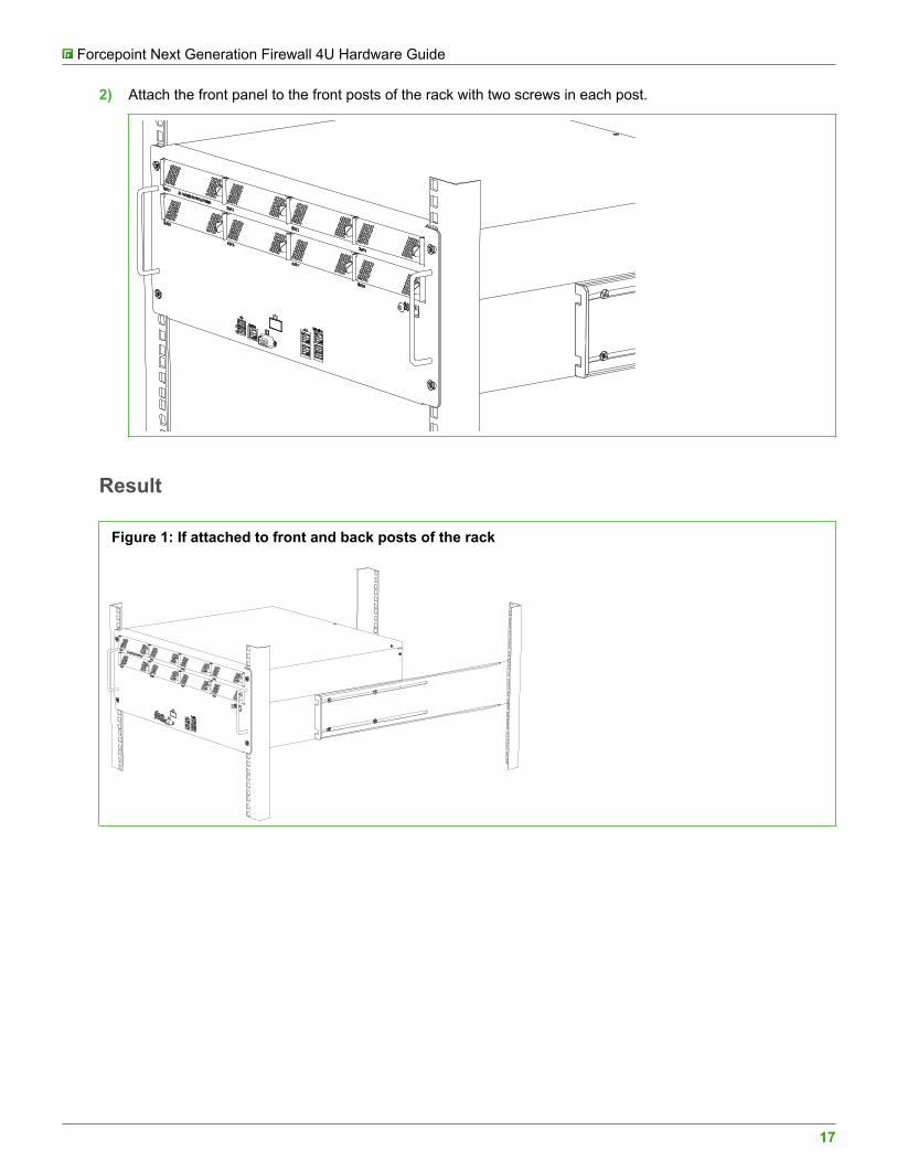
2) Attach the front panel to the front posts of the rack with two screws in each post.
Result
Figure 1: If attached to front and back posts of the rack
Forcepoint Next Generation Firewall 4U Hardware Guide
18
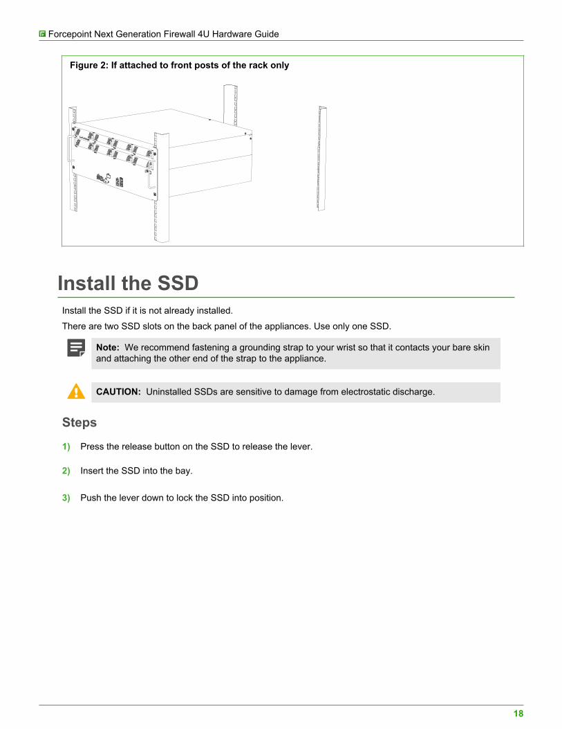
Figure 2: If attached to front posts of the rack only
Install the SSDInstall the SSD if it is not already installed.
There are two SSD slots on the back panel of the appliances. Use only one SSD.
Note: We recommend fastening a grounding strap to your wrist so that it contacts your bare skinand attaching the other end of the strap to the appliance.
CAUTION: Uninstalled SSDs are sensitive to damage from electrostatic discharge.
Steps
1) Press the release button on the SSD to release the lever.
2) Insert the SSD into the bay.
3) Push the lever down to lock the SSD into position.
Forcepoint Next Generation Firewall 4U Hardware Guide
19
Install an interface moduleIf needed, install any interface modules.
Before you begin• Read the safety precautions.• Make sure any interface modules you install are the correct type for your appliance.
CAUTION: To avoid damaging the modules or the appliance, do not install or remove anyinterface modules if the appliance is turned on.
You must install an interface module or a placeholder module in each slot before making the applianceoperational. If the appliance was delivered with a plate that covered the interface slot, you can cover the interfaceslot with the plate.
Note: We recommend fastening a grounding strap to your wrist so that it contacts your bare skinand attaching the other end of the strap to the appliance.
Steps
1) Locate the slot to install the module in.
2) If the interface slot is covered with a plate, unfasten the thumbscrew that attaches the plate to the interfacemodule slot and remove the plate.Store the plate and the thumbscrew for later use in case you want to use the appliance without an interfacemodule.
3) Push the module into the slot.The module is seated correctly when the module clicks in place with a click.
Tip: Make sure that the sticker on the module cover faces up.
Important: Do not insert the module in the wrong orientation. Inserting the modulesincorrectly might damage the appliance and the modules and voids the warranty.
Connect the cablesConnect the network, management, and power supply cables.
CAUTION: On appliances that have an Intelligent Platform Management Interface (IPMI) port,the IPMI port is disabled by default. We do not recommend that you enable the IPMI port andconnect a cable to it. This might help an unauthorized user to find a way to access and managethe appliance remotely and compromise the security of the system.
Forcepoint Next Generation Firewall 4U Hardware Guide
20
Copper cable typesUse at least CAT5e-rated cables for gigabit networks.
(IPS and Layer 2 Firewall only) Always use standard cabling methods. Use crossover cables to connect theappliance to hosts and straight cables to connect the appliance to switches or hubs.
Speed and duplex settingsNetwork interfaces at both ends of each cable must have identical speed and duplex settings.
These settings include the automatic negotiation setting. If one end of the cable uses autonegotiation, the otherend must also use autonegotiation. Gigabit standards require interfaces to use autonegotiation — fixed settingsare not allowed at gigabit speeds.(IPS and Layer 2 Firewall only) The settings for inline interfaces must be identical. All four interfaces — the pairon the appliance and the interfaces on the two devices connecting to the appliance — must have the same speedand duplex settings configured.
Ethernet port mappingFor appliances that have removable interface modules, Ethernet port names are based on the slot and portnumbers.
The first number in the name represents the slot on the appliance, and the second number represents the port onthe slot. Example: eth2_0 is located on port 0 of slot 2.• Slot 0 contains the fixed Ethernet ports.• Slots 1 and higher contain the ports on the interface modules. The port numbers start at 0 and increase from
left to right.
During the initial configuration of the appliance, the Ethernet ports are mapped to the interface IDs that youdefined in the Management Client.
The NGFW Initial Configuration Wizard displays the mapping between the interface IDs and port names. In thecommand line version of the NGFW Initial Configuration Wizard, Interface IDs appear in the Id column and portnames appear in the Name column.
This mapping can change if you replace an interface module. If the new module has a larger number of Ethernetports, the interface IDs for the new ports start from the next free interface ID number. Use the new interfaceIDs to configure new interfaces in the Management Client, then refresh the policy on the engine to transfer thechanges. See the Forcepoint Next Generation Firewall Product Guide for more information.
CAUTION: Do not select the Clear action when modifying interface IDs in the NGFW InitialConfiguration Wizard on the command line. Selecting Clear removes all mapping informationbetween interface IDs and Ethernet ports, and restores the default values.
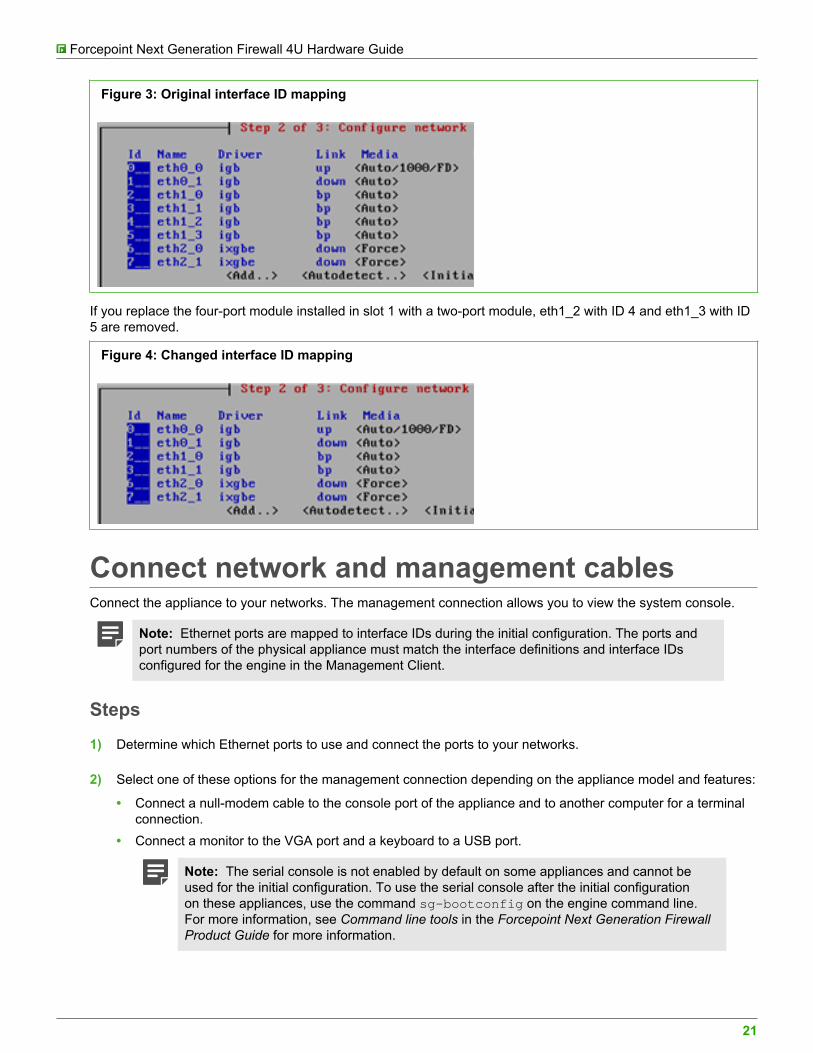
Example: You have seven interfaces numbered 1–7, which includes a four-port module installed in slot 1.
Forcepoint Next Generation Firewall 4U Hardware Guide
21
Figure 3: Original interface ID mapping
If you replace the four-port module installed in slot 1 with a two-port module, eth1_2 with ID 4 and eth1_3 with ID5 are removed.
Figure 4: Changed interface ID mapping
Connect network and management cablesConnect the appliance to your networks. The management connection allows you to view the system console.
Note: Ethernet ports are mapped to interface IDs during the initial configuration. The ports andport numbers of the physical appliance must match the interface definitions and interface IDsconfigured for the engine in the Management Client.
Steps
1) Determine which Ethernet ports to use and connect the ports to your networks.
2) Select one of these options for the management connection depending on the appliance model and features:
• Connect a null-modem cable to the console port of the appliance and to another computer for a terminalconnection.
• Connect a monitor to the VGA port and a keyboard to a USB port.
Note: The serial console is not enabled by default on some appliances and cannot beused for the initial configuration. To use the serial console after the initial configurationon these appliances, use the command sg-bootconfig on the engine command line.For more information, see Command line tools in the Forcepoint Next Generation FirewallProduct Guide for more information.
Forcepoint Next Generation Firewall 4U Hardware Guide
22
Connect network cables to SFP portsIf you installed an SFP interface module on the appliance or the appliance has an integrated SFP port, insert thecopper or fiber-optic SFP transceiver into the port, then connect the cables.
Steps
1) Insert the SFP transceiver in the port slot until you feel the connector on the transceiver snap into place.
Note: Make sure that the latch on the SFP transceiver is up when you insert the SFPtransceiver in the port slot.
2) If the SFP transceiver has a rubber plug, remove the plug.
3) Connect the copper or fiber-optic cable to the SFP transceiver.
Note: Each SFP port must match the wavelength specifications at the other end of the cable.The cable must not exceed the stipulated cable length for reliable communications.
Connect the power suppliesConnect cables to the power supplies on the back of the appliance.
Before you beginSee the safety precautions topic for information about power supplies.
We highly recommend these configurations.
• On appliances that have two power supply modules for redundant power sources, connect both powersupplies to a power source. This ensures that the appliance can function if one of the power connections fails.
• Use a UPS to ensure continuous operation and minimize the risk of damage to the appliance in case ofsudden loss of power. For a truly redundant power supply, connect each power connector on the appliance toa different UPS, so that the failure of one UPS does not cut power to both power supplies.
Steps
1) Connect the power cables to the AC or DC power connectors on the back of the appliance.
2) Plug the power cord into a grounded, high-quality power strip that offers protection from electrical noise andpower surges.
Related conceptsSafety precautions on page 12
Forcepoint Next Generation Firewall 4U Hardware Guide
23
MaintenanceForcepoint NGFW appliances ship with several replaceable components.
Turn off the applianceTurn off the appliance from the engine command line.
Steps
1) Connect to the engine command line. Depending on your appliance type, use one of these options.• Connect a keyboard to a USB port and a monitor to the VGA port, then press Enter.• Connect a computer running a terminal emulator program to the appliance console port, then press
Enter.• Connect using SSH.
Note: SSH access is not enabled by default.
2) Enter the logon credentials.The user name is root and the password is the one you set for the appliance.
3) Enter the command halt.
Replace the power supplyThe power supplies are replaceable on most Forcepoint NGFW appliances.
The power supplies are hot-swappable.
CAUTION: Do not open the casing of a power supply module. Power supply modules can only berepaired by a qualified technician from the manufacturer.
Note: We recommend fastening a grounding strap to your wrist so that it contacts your bare skinand attaching the other end of the strap to the appliance.
Steps
1) Disconnect the power cable from the power supply module.
2) Locate the release tab for the power supply module.
3) Push the release tab to release the power supply module from its locking position.
4) Pull out the power supply module using the handle provided.
Forcepoint Next Generation Firewall 4U Hardware Guide
24
5) Push the replacement power supply module into the power bay until it clicks in place.
Replace the appliance fansReplace failed fans to ensure proper cooling of the appliance.
The appliance fans are hot-swappable.
We recommend that you replace all appliance fans if one of the fans fails.
CAUTION: Do not remove all fans at the same time if the appliance is running.
Note: We recommend fastening a grounding strap to your wrist so that it contacts your bare skinand attaching the other end of the strap to the appliance.
Steps
1) Press the release tabs on the side of the appliance fan to release the fan from its locking position.
2) Remove the fan from the appliance and slide the new fan into the fan housing.
Replace the SSDReplace an SSD with another of the same model.
There are two SSD slots on the back panel of the appliance. Use only one slot.
Note: We recommend fastening a grounding strap to your wrist so that it contacts your bare skinand attaching the other end of the strap to the appliance.
CAUTION: Uninstalled SSDs are sensitive to damage from electrostatic discharge.
Steps
1) Turn off the appliance and disconnect any power cables.
2) Press the release button to release the lever that locks the SSD into position.
3) Pull the lever carefully and remove the SSD from the bay.
4) Remove the SSD from the tray, then insert the new SSD into the tray.
5) Press the release button on the new SSD to release the lever.
6) Insert the SSD into the same bay as the SSD that you removed.
Forcepoint Next Generation Firewall 4U Hardware Guide
25
7) Push the lever down to lock the SSD into position.
Replace an interface moduleReplace an interface module with the same type or a different type of module.
If the appliance was delivered with a plate that covered the interface slot, you can cover the interface slot with theplate.
If the number of ports in the old and new module are the same, the mapping between the Interface IDs stays thesame. If the number of ports in the new module is different from the old module, you might need to modify theinterface definitions.
Note: We recommend fastening a grounding strap to your wrist so that it contacts your bare skinand attaching the other end of the strap to the appliance.
Steps
1) Turn off the appliance and disconnect any power cables.
2) Release the module from its locking position by pressing and holding the lever right, then pulling the modulecarefully out of the slot using the handle or the knob on the module's front panel.
Note: If the unlocked module does not move, keep the release lever to the right, press themodule gently toward the back of the slot, and pull the module again by the handle or theknob.
3) Insert the new module.
4) Connect the cables and plug the power cables to the system and to the wall outlets.
5) Turn on the appliance.
CAUTION: To ensure proper cooling, do not turn on the appliance if you have not installedan interface module or a placeholder module in each slot. For some appliances, you caninstall the cover plate over the slot instead.
6) If the number of ports in the new module differs from the old module, update the interface configuration.
a) In the Management Client, modify the interface definitions as needed.
b) Refresh the policy to transfer the interface changes to the engine.
Forcepoint Next Generation Firewall 4U Hardware Guide
26
Reattach the cover plate to the interfacemodule slotReattach the module cover plate if there is no module in the slot.
CAUTION: Do not turn on the appliance if a slot is empty or uncovered. Using the appliancewithout an interface module or the cover plate can damage the appliance and voids the warranty.
Note: We recommend fastening a grounding strap to your wrist so that it contacts your bare skinand attaching the other end of the strap to the appliance.
Steps
1) Turn off the appliance.
2) Remove the interface module from the interface module slot.
3) Locate the tab at the lower left corner of the plate.
4) Insert the tab into the hole in the lower left corner of the slot casing.
5) Slide the plate inward until it covers the slot.
6) Push the lever down to lock the plate into position.
Remove SFP transceiversRemove or replace an SFP transceiver.
CAUTION: Invisible laser radiation is emitted from the end of a fiber-optic cable and from the fiberport. Do not stare into the beam and avoid direct exposure to the beam.
Note: We recommend fastening a grounding strap to your wrist so that it contacts your bare skinand attaching the other end of the strap to the appliance.
Steps
1) Turn off the appliance and disconnect any power cables.
2) Unplug all power cables from the system or the wall outlets.
3) Disconnect the cable from the SFP transceiver.
4) Pull down the latch on the transceiver and carefully pull the SFP transceiver out of the port slot.
5) If needed, insert a replacement SFP transceiver in the slot.

Forcepoint Next Generation Firewall 4U Hardware Guide
27
Related tasksConnect network cables to SFP ports on page 22

© 2017 ForcepointForcepoint and the FORCEPOINT logo are trademarks of Forcepoint.
Raytheon is a registered trademark of Raytheon Company.All other trademarks used in this document are the property of their respective owners.