next generation firewall 5.10.0 installation guide
TRANSCRIPT

Installation GuideRevision B
McAfee Next Generation Firewall 5.10

COPYRIGHT
Copyright © 2016 McAfee, Inc., 2821 Mission College Boulevard, Santa Clara, CA 95054, 1.888.847.8766, www.intelsecurity.com
TRADEMARK ATTRIBUTIONSIntel and the Intel logo are registered trademarks of the Intel Corporation in the US and/or other countries. McAfee and the McAfee logo, McAfee ActiveProtection, McAfee DeepSAFE, ePolicy Orchestrator, McAfee ePO, McAfee EMM, McAfee Evader, Foundscore, Foundstone, Global Threat Intelligence,McAfee LiveSafe, Policy Lab, McAfee QuickClean, Safe Eyes, McAfee SECURE, McAfee Shredder, SiteAdvisor, McAfee Stinger, McAfee TechMaster, McAfeeTotal Protection, TrustedSource, VirusScan are registered trademarks or trademarks of McAfee, Inc. or its subsidiaries in the US and other countries.Other marks and brands may be claimed as the property of others.
LICENSE INFORMATION
License AgreementNOTICE TO ALL USERS: CAREFULLY READ THE APPROPRIATE LEGAL AGREEMENT CORRESPONDING TO THE LICENSE YOU PURCHASED, WHICH SETSFORTH THE GENERAL TERMS AND CONDITIONS FOR THE USE OF THE LICENSED SOFTWARE. IF YOU DO NOT KNOW WHICH TYPE OF LICENSE YOUHAVE ACQUIRED, PLEASE CONSULT THE SALES AND OTHER RELATED LICENSE GRANT OR PURCHASE ORDER DOCUMENTS THAT ACCOMPANY YOURSOFTWARE PACKAGING OR THAT YOU HAVE RECEIVED SEPARATELY AS PART OF THE PURCHASE (AS A BOOKLET, A FILE ON THE PRODUCT CD, OR AFILE AVAILABLE ON THE WEBSITE FROM WHICH YOU DOWNLOADED THE SOFTWARE PACKAGE). IF YOU DO NOT AGREE TO ALL OF THE TERMS SETFORTH IN THE AGREEMENT, DO NOT INSTALL THE SOFTWARE. IF APPLICABLE, YOU MAY RETURN THE PRODUCT TO MCAFEE OR THE PLACE OFPURCHASE FOR A FULL REFUND.
2 McAfee Next Generation Firewall 5.10 Installation Guide

Contents
Preface 9Audience . . . . . . . . . . . . . . . . . . . . . . . . . . . . . . . . . . . . . 9Conventions . . . . . . . . . . . . . . . . . . . . . . . . . . . . . . . . . . . . 9Find product documentation . . . . . . . . . . . . . . . . . . . . . . . . . . . . . 10
Introduction to McAfee Next Generation Firewall (McAfeeNGFW)
1 Introduction to McAfee NGFW 13McAfee NGFW system components . . . . . . . . . . . . . . . . . . . . . . . . . . . 13Security Management Center (SMC) . . . . . . . . . . . . . . . . . . . . . . . . . . 14McAfee NGFW engines . . . . . . . . . . . . . . . . . . . . . . . . . . . . . . . . 14
McAfee NGFW in the Firewall/VPN role . . . . . . . . . . . . . . . . . . . . . . 15McAfee NGFW in the IPS and Layer 2 Firewall roles . . . . . . . . . . . . . . . . . 15Master Engines and Virtual Security Engines . . . . . . . . . . . . . . . . . . . . 16
2 Preparing for installation 17Supported platforms . . . . . . . . . . . . . . . . . . . . . . . . . . . . . . . . 17
Supported platforms for SMC deployment . . . . . . . . . . . . . . . . . . . . . 17Supported platforms for McAfee NGFW engine deployment . . . . . . . . . . . . . . 18Deploying McAfee NGFW engines in the Amazon Web Services cloud . . . . . . . . . . 18Running McAfee NGFW engines as Master Engines . . . . . . . . . . . . . . . . . 19
Clustering . . . . . . . . . . . . . . . . . . . . . . . . . . . . . . . . . . . . . 19Heartbeat connection and state synchronization for clusters . . . . . . . . . . . . . 19Hardware for Firewall Cluster nodes . . . . . . . . . . . . . . . . . . . . . . . 20
Deployment options for McAfee NGFW in the IPS and Layer 2 Firewall roles . . . . . . . . . . 20Cable connection guidelines . . . . . . . . . . . . . . . . . . . . . . . . . . . . . 21
Cable connection guidelines for SMC Appliance . . . . . . . . . . . . . . . . . . . 21Cable connection guidelines for Firewalls . . . . . . . . . . . . . . . . . . . . . 21Cable connection guidelines for IPS and Layer 2 Firewalls . . . . . . . . . . . . . . 22
Speed and duplex settings for McAfee NGFW engines . . . . . . . . . . . . . . . . . . . 26Obtain installation files . . . . . . . . . . . . . . . . . . . . . . . . . . . . . . . 26
Download installation files . . . . . . . . . . . . . . . . . . . . . . . . . . . 27Check file integrity . . . . . . . . . . . . . . . . . . . . . . . . . . . . . . 27Create an installation DVD . . . . . . . . . . . . . . . . . . . . . . . . . . . 27
Licensing McAfee NGFW system components . . . . . . . . . . . . . . . . . . . . . . . 28Types of licenses for McAfee NGFW engines . . . . . . . . . . . . . . . . . . . . 28Obtain license files . . . . . . . . . . . . . . . . . . . . . . . . . . . . . . 28
Installation overview . . . . . . . . . . . . . . . . . . . . . . . . . . . . . . . . 29
Security Management Center (SMC) deployment3 Installing the SMC 33
SMC installation options . . . . . . . . . . . . . . . . . . . . . . . . . . . . . . . 33
McAfee Next Generation Firewall 5.10 Installation Guide 3

Requirements for running SMC on third-party hardware . . . . . . . . . . . . . . . 34Security considerations for SMC deployment . . . . . . . . . . . . . . . . . . . . 34Basic system settings for the SMC components . . . . . . . . . . . . . . . . . . . 35Installing on Linux . . . . . . . . . . . . . . . . . . . . . . . . . . . . . . 35SMC installation overview . . . . . . . . . . . . . . . . . . . . . . . . . . . 35
Install SMC components . . . . . . . . . . . . . . . . . . . . . . . . . . . . . . . 36Start the SMC installation . . . . . . . . . . . . . . . . . . . . . . . . . . . 36Install a Management Server . . . . . . . . . . . . . . . . . . . . . . . . . . 38Install a Log Server . . . . . . . . . . . . . . . . . . . . . . . . . . . . . . 39Install a Web Portal Server . . . . . . . . . . . . . . . . . . . . . . . . . . . 40Finish the SMC installation . . . . . . . . . . . . . . . . . . . . . . . . . . . 40
Install the SMC in Demo Mode . . . . . . . . . . . . . . . . . . . . . . . . . . . . 41Install the SMC from the command line . . . . . . . . . . . . . . . . . . . . . . . . . 42
Start the SMC installation on the command line . . . . . . . . . . . . . . . . . . 43Configure the Management Server from the command line . . . . . . . . . . . . . . 44Configure the Log Server from the command line . . . . . . . . . . . . . . . . . . 45Configure the Web Portal Server from the command line . . . . . . . . . . . . . . . 46
Install the SMC Appliance . . . . . . . . . . . . . . . . . . . . . . . . . . . . . . 46Start the SMC after installation . . . . . . . . . . . . . . . . . . . . . . . . . . . . 48
Start the Management Server . . . . . . . . . . . . . . . . . . . . . . . . . . 48Start the Management Client . . . . . . . . . . . . . . . . . . . . . . . . . . 48Log on to the SMC . . . . . . . . . . . . . . . . . . . . . . . . . . . . . . 49Accept the Management Server certificate . . . . . . . . . . . . . . . . . . . . . 49Install licenses for SMC servers . . . . . . . . . . . . . . . . . . . . . . . . . 49Bind Management Server POL-bound licenses to servers . . . . . . . . . . . . . . . 50Start SMC servers . . . . . . . . . . . . . . . . . . . . . . . . . . . . . . 51Generate SMC server certificates . . . . . . . . . . . . . . . . . . . . . . . . 51
Post-installation SMC configurations . . . . . . . . . . . . . . . . . . . . . . . . . . 52
4 Configuring the SMC 53Configuring NAT addresses for SMC components . . . . . . . . . . . . . . . . . . . . . 53
Add Location elements . . . . . . . . . . . . . . . . . . . . . . . . . . . . 54Add SMC Server contact addresses . . . . . . . . . . . . . . . . . . . . . . . 55Set the Management Client location . . . . . . . . . . . . . . . . . . . . . . . 55
Add Management Servers for high availability . . . . . . . . . . . . . . . . . . . . . . 56Distribute Management Clients through Web Start . . . . . . . . . . . . . . . . . . . . 57
Distribute Management Clients from SMC servers . . . . . . . . . . . . . . . . . . 58Distribute Management Clients from a separate server . . . . . . . . . . . . . . . . 59
McAfee NGFW engine deployment5 Configuring McAfee NGFW for the Firewall/VPN role 63
Install licenses for McAfee NGFW engines . . . . . . . . . . . . . . . . . . . . . . . . 63Configuring Single Firewalls . . . . . . . . . . . . . . . . . . . . . . . . . . . . . 64
Types of interfaces for Single Firewalls . . . . . . . . . . . . . . . . . . . . . . 64Add Single Firewall elements . . . . . . . . . . . . . . . . . . . . . . . . . . 65Add physical interfaces to Single Firewalls . . . . . . . . . . . . . . . . . . . . . 66Add VLAN interfaces to Single Firewalls . . . . . . . . . . . . . . . . . . . . . . 67Add ADSL Interfaces to Single Firewalls . . . . . . . . . . . . . . . . . . . . . . 67Add wireless interfaces to Single Firewalls . . . . . . . . . . . . . . . . . . . . . 68Add SSID Interfaces to Single Firewalls . . . . . . . . . . . . . . . . . . . . . . 69Add Switches to Single Firewalls . . . . . . . . . . . . . . . . . . . . . . . . . 70Add Port Group Interfaces to Single Firewalls . . . . . . . . . . . . . . . . . . . 71Add IP addresses for Single Firewall interfaces . . . . . . . . . . . . . . . . . . . 71Add Modem Interfaces to Single Firewalls . . . . . . . . . . . . . . . . . . . . . 75Select system communication roles for Single Firewall interfaces . . . . . . . . . . . 76
Contents
4 McAfee Next Generation Firewall 5.10 Installation Guide
Bind engine licenses to Single Firewall elements . . . . . . . . . . . . . . . . . . 77Configuring Firewall Clusters . . . . . . . . . . . . . . . . . . . . . . . . . . . . . 77
Types of interfaces for Firewall Clusters . . . . . . . . . . . . . . . . . . . . . . 77Operating modes for Firewall Cluster interfaces . . . . . . . . . . . . . . . . . . 78Add Firewall Cluster elements . . . . . . . . . . . . . . . . . . . . . . . . . . 79Add nodes to Firewall Clusters . . . . . . . . . . . . . . . . . . . . . . . . . 79Add physical interfaces to Firewall Clusters . . . . . . . . . . . . . . . . . . . . 80Add VLAN Interfaces to Firewall Clusters . . . . . . . . . . . . . . . . . . . . . 81Add IP addresses for Firewall Cluster interfaces . . . . . . . . . . . . . . . . . . 81Select system communication roles for Firewall Cluster interfaces . . . . . . . . . . . 84Add manual ARP entries for Firewall Clusters . . . . . . . . . . . . . . . . . . . 85Bind engine licenses to Firewall Cluster elements . . . . . . . . . . . . . . . . . . 86
6 Configuring McAfee NGFW for the IPS role 87Configuring IPS engines . . . . . . . . . . . . . . . . . . . . . . . . . . . . . . . 87
Add IPS elements . . . . . . . . . . . . . . . . . . . . . . . . . . . . . . 88Add system communication interfaces to IPS engines . . . . . . . . . . . . . . . . 88Add traffic inspection interfaces to IPS engines . . . . . . . . . . . . . . . . . . . 94
Bind engine licenses to IPS elements . . . . . . . . . . . . . . . . . . . . . . . . . . 98
7 Configuring McAfee NGFW for the Layer 2 Firewall role 101Configuring Layer 2 Firewalls . . . . . . . . . . . . . . . . . . . . . . . . . . . . 101
Add Layer 2 Firewall elements . . . . . . . . . . . . . . . . . . . . . . . . . 102Add system communications interfaces to Layer 2 Firewalls . . . . . . . . . . . . . 102Add traffic inspection interfaces to Layer 2 Firewalls . . . . . . . . . . . . . . . . 108
Bind engine licenses to Layer 2 Firewall elements . . . . . . . . . . . . . . . . . . . . 112
8 Configuring McAfee NGFW engines as Master Engines and Virtual Security Engines113
Master Engine and Virtual Security Engine configuration overview . . . . . . . . . . . . . . 113Add Master Engine elements . . . . . . . . . . . . . . . . . . . . . . . . . . . . . 114
Add nodes to Master Engines . . . . . . . . . . . . . . . . . . . . . . . . . 115Create Virtual Resource elements . . . . . . . . . . . . . . . . . . . . . . . . 115Add physical interfaces to Master Engines . . . . . . . . . . . . . . . . . . . . 116Add VLAN interfaces to Master Engines . . . . . . . . . . . . . . . . . . . . . 117Add IPv4 and IPv6 addresses to Master Engine interfaces . . . . . . . . . . . . . . 118Select system communication roles for Master Engine interfaces . . . . . . . . . . . 119Bind Master Engine licenses to Master Engine elements . . . . . . . . . . . . . . . 120
Add Virtual Firewall elements . . . . . . . . . . . . . . . . . . . . . . . . . . . . 121Configuring physical interfaces for Virtual Firewalls . . . . . . . . . . . . . . . . . 121Add VLAN interfaces to Virtual Security Engine interfaces . . . . . . . . . . . . . . 122Add IP addresses for Virtual Firewalls . . . . . . . . . . . . . . . . . . . . . . 122Select additional options for Virtual Firewall interfaces . . . . . . . . . . . . . . . 124
Add Virtual IPS elements . . . . . . . . . . . . . . . . . . . . . . . . . . . . . . 124Configuring physical interfaces for Virtual IPS engines . . . . . . . . . . . . . . . 125
Add Virtual Layer 2 Firewall elements . . . . . . . . . . . . . . . . . . . . . . . . . 125Configuring Physical Interfaces for Virtual Layer 2 Firewalls . . . . . . . . . . . . . 126
9 Configuring McAfee NGFW engine software 127Options for initial configuration . . . . . . . . . . . . . . . . . . . . . . . . . . . . 127Using plug and play configuration . . . . . . . . . . . . . . . . . . . . . . . . . . . 128
Prepare for plug and play configuration . . . . . . . . . . . . . . . . . . . . . 128Configure McAfee NGFW engine software using plug and play configuration . . . . . . . 129If plug and play configuration fails . . . . . . . . . . . . . . . . . . . . . . . 130
Using automatic configuration . . . . . . . . . . . . . . . . . . . . . . . . . . . . 130Prepare for automatic configuration . . . . . . . . . . . . . . . . . . . . . . . 130
Contents
McAfee Next Generation Firewall 5.10 Installation Guide 5

Configure McAfee NGFW engine software using automatic configuration . . . . . . . . 132Configure McAfee NGFW engine software with the McAfee NGFW Configuration Wizard . . . . . 132
Prepare for McAfee NGFW Configuration Wizard configuration . . . . . . . . . . . . 133Start the McAfee NGFW Configuration Wizard . . . . . . . . . . . . . . . . . . . 134Configure operating system settings . . . . . . . . . . . . . . . . . . . . . . 135Configure the network interfaces . . . . . . . . . . . . . . . . . . . . . . . . 136Contact the Management Server . . . . . . . . . . . . . . . . . . . . . . . . 137
10 McAfee NGFW engine post-installation tasks 139Configuring routing and basic policies . . . . . . . . . . . . . . . . . . . . . . . . . 139
Configuring routing . . . . . . . . . . . . . . . . . . . . . . . . . . . . . 139Defining basic policies for firewalls . . . . . . . . . . . . . . . . . . . . . . . 143Installing the initial policy for IPS engines and Layer 2 Firewalls . . . . . . . . . . . 145Install a ready-made policy for IPS engines and Layer 2 Firewalls . . . . . . . . . . . 147
Monitor and command McAfee NGFW engines . . . . . . . . . . . . . . . . . . . . . . 147
Maintenance11 Maintaining the SMC 151
Upgrading the SMC . . . . . . . . . . . . . . . . . . . . . . . . . . . . . . . . 151Upgrading licenses for SMC components . . . . . . . . . . . . . . . . . . . . . 152Upgrade SMC servers . . . . . . . . . . . . . . . . . . . . . . . . . . . . 153Synchronize databases between active Management Server and additional Management Servers. . . . . . . . . . . . . . . . . . . . . . . . . . . . . . . . . . . . . 154
Uninstall the SMC . . . . . . . . . . . . . . . . . . . . . . . . . . . . . . . . . 155Uninstall the SMC in Windows . . . . . . . . . . . . . . . . . . . . . . . . . 156Uninstall the SMC in Linux . . . . . . . . . . . . . . . . . . . . . . . . . . 156
12 Upgrading McAfee NGFW engines 157How engine upgrades work . . . . . . . . . . . . . . . . . . . . . . . . . . . . . 157Obtain McAfee NGFW engine upgrade files . . . . . . . . . . . . . . . . . . . . . . . 158Upgrading or generating licenses for McAfee NGFW engines . . . . . . . . . . . . . . . . 160
Upgrade licenses under one proof code . . . . . . . . . . . . . . . . . . . . . 160Upgrade licenses with multiple proof codes . . . . . . . . . . . . . . . . . . . . 160Check licenses . . . . . . . . . . . . . . . . . . . . . . . . . . . . . . . 161
Upgrade engines remotely . . . . . . . . . . . . . . . . . . . . . . . . . . . . . 162Upgrade engines locally . . . . . . . . . . . . . . . . . . . . . . . . . . . . . . 163
Upgrade from an installation DVD . . . . . . . . . . . . . . . . . . . . . . . 164Upgrade from a .zip file . . . . . . . . . . . . . . . . . . . . . . . . . . . . 164
A Default communication ports 167Security Management Center ports . . . . . . . . . . . . . . . . . . . . . . . . . . 168McAfee NGFW engine ports . . . . . . . . . . . . . . . . . . . . . . . . . . . . . 171
B Command line tools 175Security Management Center commands . . . . . . . . . . . . . . . . . . . . . . . . 175McAfee NGFW engine commands . . . . . . . . . . . . . . . . . . . . . . . . . . . 190Server Pool Monitoring Agent commands . . . . . . . . . . . . . . . . . . . . . . . . 198
C Installing McAfee NGFW engines on a virtualization platform 199Hardware requirements for installing McAfee NGFW engines on a virtualization platform . . . . . 199Install McAfee NGFW engine using an .iso file . . . . . . . . . . . . . . . . . . . . . . 200Install McAfee NGFW engine using a VMDK image . . . . . . . . . . . . . . . . . . . . 201
D Installing McAfee NGFW engines on third-party hardware 203Hardware requirements for installing McAfee NGFW engines on third-party hardware . . . . . . 203
Contents
6 McAfee Next Generation Firewall 5.10 Installation Guide

Network interface cards . . . . . . . . . . . . . . . . . . . . . . . . . . . 204Hardware drivers . . . . . . . . . . . . . . . . . . . . . . . . . . . . . . 204
Start the McAfee NGFW engine installation on third-party hardware . . . . . . . . . . . . . 208Install McAfee NGFW in expert mode . . . . . . . . . . . . . . . . . . . . . . . . . 208
Partition the hard disk in expert mode . . . . . . . . . . . . . . . . . . . . . . 209Allocate partitions in expert mode . . . . . . . . . . . . . . . . . . . . . . . 209
E Example network (Firewall/VPN) 211Example Firewall Cluster . . . . . . . . . . . . . . . . . . . . . . . . . . . . . . 212Example Single Firewall . . . . . . . . . . . . . . . . . . . . . . . . . . . . . . 214Example headquarters management network . . . . . . . . . . . . . . . . . . . . . . 214
HQ firewall . . . . . . . . . . . . . . . . . . . . . . . . . . . . . . . . . 215SMC Servers . . . . . . . . . . . . . . . . . . . . . . . . . . . . . . . . 215
F Example network (IPS) 217Example network overview (IPS) . . . . . . . . . . . . . . . . . . . . . . . . . . . 217Example headquarters intranet network . . . . . . . . . . . . . . . . . . . . . . . . 218HQ IPS Cluster . . . . . . . . . . . . . . . . . . . . . . . . . . . . . . . . . . 218Example headquarters DMZ network . . . . . . . . . . . . . . . . . . . . . . . . . 219
DMZ IPS . . . . . . . . . . . . . . . . . . . . . . . . . . . . . . . . . . 219
G Cluster installation worksheet instructions 221Cluster installation worksheet . . . . . . . . . . . . . . . . . . . . . . . . . . . . 221
Index 223
Contents
McAfee Next Generation Firewall 5.10 Installation Guide 7

Contents
8 McAfee Next Generation Firewall 5.10 Installation Guide

Preface
This guide provides the information you need to work with your McAfee product.
Contents Audience Conventions Find product documentation
AudienceMcAfee documentation is carefully researched and written for the target audience.
The information in this guide is intended primarily for:
• Administrators — People who implement and enforce the company's security program.
• Users — People who use the computer where the software is running and can access some or all ofits features.
ConventionsThis guide uses these typographical conventions and icons.
Book title, term,emphasis
Title of a book, chapter, or topic; a new term; emphasis.
Bold Text that is strongly emphasized.
User input, code,message
Commands and other text that the user types; a code sample; a displayedmessage.
Interface text Words from the product interface like options, menus, buttons, and dialogboxes.
Hypertext blue A link to a topic or to an external website.
Note: Additional information, like an alternate method of accessing anoption.
Tip: Suggestions and recommendations.
Important/Caution: Valuable advice to protect your computer system,software installation, network, business, or data.
Warning: Critical advice to prevent bodily harm when using a hardwareproduct.
McAfee Next Generation Firewall 5.10 Installation Guide 9

Find product documentationOn the ServicePortal, you can find information about a released product, including productdocumentation, technical articles, and more.
Task1 Go to the ServicePortal at https://support.mcafee.com and click the Knowledge Center tab.
2 In the Knowledge Base pane under Content Source, click Product Documentation.
3 Select a product and version, then click Search to display a list of documents.
PrefaceFind product documentation
10 McAfee Next Generation Firewall 5.10 Installation Guide

Introduction to McAfee NextGeneration Firewall (McAfeeNGFW)Before setting up McAfee NGFW, it is useful to know what the differentcomponents do and what engine roles are available. There are also tasksthat you must complete to prepare for installation.
Chapter 1 Introduction to McAfee NGFWChapter 2 Preparing for installation
McAfee Next Generation Firewall 5.10 Installation Guide 11

Introduction to McAfee Next Generation Firewall (McAfee NGFW)
12 McAfee Next Generation Firewall 5.10 Installation Guide

1 Introduction to McAfee NGFW
The McAfee®
Next Generation Firewall (McAfee NGFW) system consists of the McAfee NGFW enginesand the Security Management Center (SMC) for managing the engines.
Contents McAfee NGFW system components Security Management Center (SMC) McAfee NGFW engines
McAfee NGFW system componentsThe McAfee NGFW system consists of one or more McAfee NGFW engines, and the SecurityManagement Center (SMC). The SMC is the management component of the McAfee NGFW system.
The system includes SMC user interface components, SMC server components, and McAfee NGFWengines.
Figure 1-1 McAfee NGFW system components
1
McAfee Next Generation Firewall 5.10 Installation Guide 13

Number Component Description
1 ManagementClient
The Management Client is the user interface for the SMC. You use theManagement Client for all configuration and monitoring tasks. You caninstall the Management Client locally as an application, or you canstart the Management Client with a web browser using the Java WebStart feature. You can install an unlimited number of ManagementClients.
2 Web Portal The Web Portal is the browser-based user interface for the servicesprovided by the Web Portal Server.
3 ManagementServer
The Management Server is the central component for systemadministration. One Management Server can manage many differenttypes of engines.
4 Log Server Log Servers store traffic logs that can be managed and compiled intoreports. Log Servers also correlate events, monitor the status ofengines, show real-time statistics, and forward logs to third-partydevices.
5 Web Portal Server The Web Portal Server is a separately licensed optional componentthat provides restricted access to log data, reports, and policysnapshots.
6 McAfee NGFWengines
McAfee NGFW engines inspect traffic. You can use McAfee NGFWengines in the following roles:• Firewall/VPN
• IPS
• Layer 2 Firewall
Security Management Center (SMC)The basic SMC components are the Management Server, Log Server, and one or more ManagementClients.
The Management Client is the user interface for the SMC. You can use the same SMC installation tomanage multiple McAfee NGFW engines in different roles.
The SMC can optionally include multiple Management Servers, multiple Log Servers, and multiple WebPortal Servers. Your licenses specify the type and number of optional components and engines thatyour environment can include. You can install the SMC components separately on different computersor on the same computer, depending on your performance requirements. The SMC all-in-one applianceis shipped with the Management Server and a Log Server pre-installed on it.
McAfee NGFW enginesYou can use McAfee NGFW engines in the Firewall/VPN, IPS, and Layer 2 Firewall roles. You can alsouse McAfee NGFW engines as Master Engines to host Virtual Security Engines in these roles.
McAfee NGFW engines are represented by different types of Security Engine elements in the SMC. Thefollowing elements represent McAfee NGFW engines in the SMC:
1 Introduction to McAfee NGFWSecurity Management Center (SMC)
14 McAfee Next Generation Firewall 5.10 Installation Guide

Engine Role Elements
Firewall/VPN Single Firewall elements represent firewalls that consist of one physical device.
Firewall Cluster elements consist of 2–16 physical firewall devices that worktogether as a single entity.
IPS Single IPS elements represent IPS engines that consist of one physical IPS device.
IPS Cluster elements combine 2–16 physical IPS devices into a single entity.
Layer 2 Firewall Single Layer 2 Firewall elements represent Layer 2 Firewalls that consist of onephysical device.
Layer 2 Firewall Cluster elements combine 2–16 physical Layer 2 Firewall devicesinto a single entity.
These elements are containers for the main configuration information directly related to the McAfeeNGFW engines.
McAfee NGFW in the Firewall/VPN roleIn addition to standard firewall features, McAfee NGFW in the Firewall/VPN role provides severaladvanced features.
The main features of McAfee NGFW in the Firewall/VPN role include:
• Advanced traffic inspection — Multi-Layer packet and connection verification process providesmaximum security without compromising system throughput. An anti-malware scanner, andanti-spam and web filtering complement the standard traffic inspection features when the firewallis licensed for the UTM (unified threat management) feature. Anti-malware and anti-spam are notsupported on Virtual Firewalls. Master Engines do not directly inspect traffic.
• Built-in load balancing and high availability — The clustering of the firewall engines isintegrated. The firewall engines dynamically load-balance individual connections between thecluster nodes.
• Multi-Link technology — Multi-Link allows configuring redundant network connections withoutthe more complex traditional solutions that require redundant external routers and switches. Itprovides high availability for inbound, outbound, and VPN connections.
• QoS and bandwidth management — You can set up the minimum and maximum bandwidthvalue and the priority value for different types of traffic.
• Virtual private networks — The firewall provides fast, secure, and reliable VPN connections withthe added benefits of the clustering and Multi-Link technologies. These features provide loadbalancing and failover between ISPs and VPN gateways.
• Unified SMC and integration with other security engines — You can configure and monitorthe Firewall/VPN and the other security engines through the same SMC and the same userinterface. The SMC provides extensive reporting tools for generating statistical reports based onlogs, alerts, and operating statistics.
McAfee NGFW in the IPS and Layer 2 Firewall rolesIPS Engines and Layer 2 Firewalls pick up network traffic, inspect it, and create event data for furtherprocessing by the Log Server.
The main features of McAfee NGFW in the IPS and Layer 2 Firewall roles include:
Introduction to McAfee NGFWMcAfee NGFW engines 1
McAfee Next Generation Firewall 5.10 Installation Guide 15

• Multiple detection methods — Misuse detection uses fingerprints to detect known attacks.Anomaly detection uses traffic statistics to detect unusual network behavior. Protocol validationidentifies violations of the defined protocol for a particular type of traffic. Event correlationprocesses event information to detect a pattern of events that might indicate an intrusion attempt.
• Response mechanisms — There are several response mechanisms to anomalous traffic. Theseinclude different alerting channels, traffic recording, TCP connection termination, traffic blacklisting,and traffic blocking with Inline Interfaces.
• Unified SMC and integration with other security engines — The IPS engines, Layer 2Firewalls, Master Engines, Virtual IPS Engines, and Virtual Layer 2 Firewalls are managed centrallythrough the SMC. The SMC provides extensive reporting tools for generating statistical reportsbased on logs, alerts, and operating statistics.
Master Engines and Virtual Security EnginesMaster Engines are physical devices that provide resources for multiple Virtual Security Engines.
Any McAfee NGFW engine that has a license that allows the creation of Virtual Resources can be usedas a Master Engine. Virtual Security Engines are represented by the following elements in the SMC:
• Virtual Firewall is a Virtual Security Engine in the Firewall/VPN role.
• Virtual IPS Engine is a Virtual Security Engine in the IPS role.
• Virtual Layer 2 Firewall is a Virtual Security Engine in the Layer 2 Firewall role.
Each Master Engine can only host one Virtual Security Engine role. To use more than one VirtualSecurity Engine role, you must create a separate Master Engine for each Virtual Security Engine role.Each Master Engine must be on a separate physical Master Engine device.
1 Introduction to McAfee NGFWMcAfee NGFW engines
16 McAfee Next Generation Firewall 5.10 Installation Guide

2 Preparing for installation
Before installing McAfee NGFW, identify the components of your McAfee NGFW installation and howthey integrate into your environment.
Contents Supported platforms Clustering Deployment options for McAfee NGFW in the IPS and Layer 2 Firewall roles Cable connection guidelines Speed and duplex settings for McAfee NGFW engines Obtain installation files Licensing McAfee NGFW system components Installation overview
Supported platformsSeveral platforms are supported for deploying McAfee NGFW engines and SMC components.
Supported platforms for SMC deploymentSMC server components can be installed on third-party hardware or they are available as a dedicatedMcAfee
®
Security Management Center Appliance (SMC Appliance).
Third-party hardware
Do not install the SMC components on the McAfee NGFW engine hardware.
• You can install the McAfee SMC on third-party hardware that meets the hardware requirements.The hardware requirements can be found at http://support.mcafee.com.
• You can install all SMC server components on the same computer, or install separate componentson different computers.
• In a large or geographically distributed deployment, we recommend installing the ManagementServer, Log Server, and optional Web Portal Server on separate computers.
SMC Appliance
The Management Server and a Log Server are integrated with the hardware operating system as adedicated server appliance.
2
McAfee Next Generation Firewall 5.10 Installation Guide 17

Management Client
Although the Web Start distribution of the Management Client is certified to run only on the listedofficial platforms, it can run on other platforms. These platforms include Mac OS X and additionalLinux distributions with JRE (Java Runtime Environment) installed.
Supported platforms for McAfee NGFW engine deploymentYou can run McAfee NGFW engines on various platforms.
The following general types of platforms are available for McAfee NGFW engines:
• Purpose-built McAfee NGFW appliances
For information about the supported appliance models, see KB78906.
• Virtualization platforms
VMware ESX, KVM, Oracle VM server, and Wind River Titanium Server are officially supported.Other virtualization platforms might also be supported.
Deployment on VMware NSX is supported only with Intel®
Security Controller integration.
• Amazon Web Services (AWS) cloud
• Third-party hardware that meets the hardware requirements
The McAfee NGFW engine software includes an integrated, hardened Linux operating system. Theoperating system eliminates the need for separate installation, configuration, and patching.
See also Hardware requirements for installing McAfee NGFW engines on third-party hardware on page203
Deploying McAfee NGFW engines in the Amazon Web ServicescloudYou can deploy McAfee NGFW engines in the Amazon Web Services (AWS) cloud to provide VPNconnectivity, access control, and inspection for services in the AWS cloud.
When you deploy McAfee NGFW engines in the AWS cloud, only the Firewall/VPN role is supported.Firewall Clusters, Master Engines, and Virtual Firewalls are not supported.
For deployment instructions and supported features, see KB85949. After deployment, you can manageMcAfee NGFW engines in the AWS cloud using the Management Client in the same way as otherMcAfee NGFW engines. However, you cannot remotely upgrade McAfee NGFW engines in the AWScloud using the Management Client. You must upgrade these engines using the AWS cloudmanagement infrastructure. For upgrade instructions, see KB85950.
Two licensing models are available for McAfee NGFW in the AWS cloud. Two engine image platformsare available, depending on the licensing model:
• Bring Your Own License — Pay only Amazon's standard runtime fee for the engine instance. You mustinstall a license for the engine in the SMC.
• Hourly (pay as you go license) — You pay Amazon's standard runtime fee for the engine instanceplus an hourly license fee based on the runtime of the engine. No license installation is needed forthe engine in the SMC.
The SMC automatically detects which platform the engine image is running on for features that requireseparate licenses.
2 Preparing for installationSupported platforms
18 McAfee Next Generation Firewall 5.10 Installation Guide

Running McAfee NGFW engines as Master EnginesThere are some hardware requirements and configuration limitations when you use a McAfee NGFWengine as a Master Engine.Running the McAfee NGFW engine as a Master Engine does not require a third-party virtualizationplatform. When you run McAfee NGFW as a Master Engine, the McAfee NGFW hardware provides thevirtual environment and resources for the hosted Virtual Security Engines. You must always install theMcAfee NGFW software on a hardware device to run the McAfee NGFW engine as a Master Engine.
You can run Master Engines on the following types of hardware platforms:
• Purpose-built McAfee NGFW appliances with 64-bit architecture
• Third-party hardware with 64-bit architecture that meets the hardware requirements
The following requirements and limitations apply when you use a McAfee NGFW engine as a MasterEngine:
• Each Master Engine must run on a separate 64-bit physical device.
• All Virtual Security Engines hosted by a Master Engine or Master Engine cluster must have thesame role and the same Failure Mode (fail-open or fail-close).
• Master Engines can allocate VLANs or interfaces to Virtual Security Engines. If the Failure Mode ofthe Virtual IPS engines or Virtual Layer 2 Firewalls is Normal (fail-close) and you want to allocateVLANs to several engines, you must use the Master Engine cluster in standby mode.
See also Hardware requirements for installing McAfee NGFW engines on third-party hardware on page203
ClusteringThere are special considerations when you deploy a McAfee NGFW engine as a Firewall Cluster, IPSCluster, or Layer 2 Firewall Cluster.
Heartbeat connection and state synchronization for clustersThe nodes in a cluster use a heartbeat connection to monitor the other nodes’ operation and tosynchronize their state tables.The nodes in a cluster exchange status information through a heartbeat network using multicasttransmissions. If a node becomes unavailable, the other nodes of the cluster immediately notice thechange, and connections are reallocated to the available nodes. A dedicated network is recommendedfor at least the primary heartbeat communications.
The heartbeat connection is essential for the operation of the cluster. Make sure that these conditionsare true:
• The heartbeat network works correctly and reliably.
• You are using the correct type of network cables (after testing that they work).
• The network interface cards’ duplex and speed settings match.
• Any network devices between the nodes are correctly configured.
It is possible to authenticate and encrypt the heartbeat traffic.
Problems in the heartbeat network might seriously degrade the performance and operation of thecluster.
Preparing for installationClustering 2
McAfee Next Generation Firewall 5.10 Installation Guide 19
In the Firewall/VPN role, the nodes of a Firewall Cluster periodically exchange synchronizationmessages to synchronize state data.
Hardware for Firewall Cluster nodesYou can run different nodes of the same cluster on different types of hardware.
The hardware the cluster nodes run on does not need to be identical. Different types of equipment canbe used as long as all nodes have enough network interfaces for your configuration. Firewall Clusterscan run on a McAfee NGFW appliance, on a standard server with an Intel-compatible processor, or as avirtual machine on a virtualization platform.
If equipment with different performance characteristics is clustered together, the load-balancingtechnology automatically distributes the load so that lower performance nodes handle less traffic thanthe higher performance nodes. However, when a node goes offline, the remaining nodes must be ableto handle all traffic on their own to ensure High Availability. For this reason, it is usually best to clusternodes with similar performance characteristics.
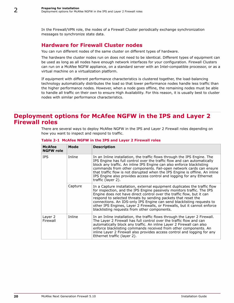
Deployment options for McAfee NGFW in the IPS and Layer 2Firewall roles
There are several ways to deploy McAfee NGFW in the IPS and Layer 2 Firewall roles depending onhow you want to inspect and respond to traffic.
Table 2-1 McAfee NGFW in the IPS and Layer 2 Firewall roles
McAfeeNGFW role
Mode Description
IPS Inline In an Inline installation, the traffic flows through the IPS Engine. TheIPS Engine has full control over the traffic flow and can automaticallyblock any traffic. An inline IPS Engine can also enforce blacklistingcommands from other components. Fail-open network cards can ensurethat traffic flow is not disrupted when the IPS Engine is offline. An inlineIPS Engine also provides access control and logging for any Ethernettraffic (layer 2).
Capture In a Capture installation, external equipment duplicates the traffic flowfor inspection, and the IPS Engine passively monitors traffic. The IPSEngine does not have direct control over the traffic flow, but it canrespond to selected threats by sending packets that reset theconnections. An IDS-only IPS Engine can send blacklisting requests toother IPS Engines, Layer 2 Firewalls, or Firewalls, but it cannot enforceblacklisting requests from other components.
Layer 2Firewall
Inline In an Inline installation, the traffic flows through the Layer 2 Firewall.The Layer 2 Firewall has full control over the traffic flow and canautomatically block any traffic. An inline Layer 2 Firewall can alsoenforce blacklisting commands received from other components. Aninline Layer 2 Firewall also provides access control and logging for anyEthernet traffic (layer 2).
2 Preparing for installationDeployment options for McAfee NGFW in the IPS and Layer 2 Firewall roles
20 McAfee Next Generation Firewall 5.10 Installation Guide

Table 2-1 McAfee NGFW in the IPS and Layer 2 Firewall roles (continued)
McAfeeNGFW role
Mode Description
Capture(PassiveFirewall)
In a Capture (Passive Firewall) installation, external equipmentduplicates the traffic flow for inspection to the Layer 2 Firewall, and theLayer 2 Firewall passively monitors traffic.
The Layer 2 Firewall does not have direct control over the traffic flow,but it can respond to selected threats by sending packets that reset theconnections. A Layer 2 Firewall in Passive Firewall mode can sendblacklisting requests to other Layer 2 Firewalls, IPS engines, orFirewalls. It cannot enforce blacklisting requests from othercomponents.
PassiveInline
In a Passive Inline installation, the traffic flows through the Layer 2Firewall, but the Layer 2 Firewall only logs connections. A Layer 2Firewall in Passive inline mode can send blacklisting requests to otherLayer 2 Firewalls, IPS engines, or Firewalls. It cannot enforceblacklisting requests from other components.
You can connect Capture Interfaces on an IPS engine or a Layer 2 Firewall to a Switched Port Analyzer(SPAN) port or a network Test Access Port (TAP) to capture network traffic.
A SPAN port captures network traffic to a defined port on an external switch. This action is also knownas port mirroring. The capturing is passive, so it does not interfere with the traffic. All traffic to bemonitored must be copied to this SPAN port.
A network TAP is a passive device at the network wire between network devices. The capturing is donepassively, so it does not interfere with the traffic. With a network TAP, the two directions of thenetwork traffic are divided to separate wires. For this reason, the IPS Engine or Layer 2 Firewall needstwo capture interfaces for a network TAP; one capture interface for each direction of the traffic. Thetwo related capture interfaces must have the same logical interface that combines the traffic of thesetwo interfaces for inspection. You could also use the pair of capture interfaces to monitor traffic in twoseparate network devices.
Cable connection guidelinesFollow these cable connection guidelines when connecting cables to McAfee NGFW hardware and SMCappliances.
Cable connection guidelines for SMC ApplianceFor an SMC Appliance, make sure that all copper cables are correctly rated (CAT 5e or CAT 6 in gigabitnetworks).
Cable connection guidelines for Firewalls The cabling of Firewalls depends on the engine type and the installation.
Make sure that all copper cables are correctly rated (CAT 5e or CAT 6 in gigabit networks).
If you have a two-node Firewall Cluster, it is recommended to use a crossover cable without anyintermediary devices between the nodes. If you use an external switch between the nodes, followthese guidelines:
Preparing for installationCable connection guidelines 2
McAfee Next Generation Firewall 5.10 Installation Guide 21

• Make sure that portfast is enabled on the external switches.
• Make sure that the speed/duplex settings of the external switches and the Firewall devices are setto Auto.
• Configure the external switches to forward multicast traffic.
Cable connection guidelines for IPS and Layer 2 FirewallsThe cabling of IPS engines and Layer 2 Firewalls depends on the engine type and the installation.
Make sure that all copper cables are correctly rated (CAT 5e or CAT 6 in gigabit networks).
Follow standard cable connections with inline IPS Engines and Layer 2 Firewalls:
• Use straight cables to connect the IPS engines and Layer 2 Firewalls to external switches.
• Use crossover cables to connect the IPS engines and Layer 2 Firewalls to hosts (such as routers orFirewalls).
Fail-open network interface cards support Auto-MDIX, so both crossover and straight cables might workwhen the IPS Engine is online. However, only the correct type of cable allows traffic to flow when theIPS Engine is offline and the fail-open network interface card is in bypass state. It is recommended totest the IPS deployment in offline state to make sure that the correct cables are used.
Cable connections for Master Engines that host Virtual IPS Engines or Virtual Layer 2 Firewalls followthe same principles as the connections for inline IPS Engines and Layer 2 Firewalls.
Figure 2-1 Correct cable types for Single IPS engines and Single Layer 2 Firewalls
2 Preparing for installationCable connection guidelines
22 McAfee Next Generation Firewall 5.10 Installation Guide

Figure 2-2 Correct cable types for Serial IPS Clusters
Preparing for installationCable connection guidelines 2
McAfee Next Generation Firewall 5.10 Installation Guide 23

Figure 2-3 Correct cable types for Active/Standby Layer 2 Firewall Clusters
2 Preparing for installationCable connection guidelines
24 McAfee Next Generation Firewall 5.10 Installation Guide

Figure 2-4 Correct cable types for Serial Virtual IPS Clusters
Figure 2-5 Correct cable types for Active/Standby Virtual Layer 2 Firewall Clusters
Preparing for installationCable connection guidelines 2
McAfee Next Generation Firewall 5.10 Installation Guide 25

Speed and duplex settings for McAfee NGFW enginesMismatched speed and duplex settings are a frequent source of networking problems.
The basic principle for speed and duplex settings is that network cards at both ends of each cablemust have identical settings. This principle also applies to the automatic negotiation setting: if one endof the cable is set to auto-negotiate, the other end must also be set to auto-negotiate and not to anyfixed setting. Gigabit standards require interfaces to use auto-negotiation. Fixed settings are notallowed at gigabit speeds.
For Inline Interfaces, the settings must be identical on both links within each Inline Interface pair. Useidentical settings on all four interfaces, instead of just matching settings at both ends of each cable(two + two interfaces). If one of the links has a lower maximum speed than the other link, thehigher-speed link must be set to use the lower speed.
Figure 2-6 Speed/duplex settings
Obtain installation filesIf you did not receive an installation DVD for the McAfee NGFW engines or the SMC, downloadinstallation files and create a DVD.
You do not have to create a DVD under these circumstances:
• McAfee NGFW engines and SMC Appliances are delivered with the necessary software pre-installedon them. You do not need to download installation files.
• You might have received ready-made installation DVDs of the McAfee NGFW software and the SMCsoftware.
Tasks
• Download installation files on page 27Download the files you need to create an installation DVD.
• Check file integrity on page 27Before installing the McAfee NGFW engine from downloaded files, check that the installationfiles have not become corrupt or been changed.
2 Preparing for installationSpeed and duplex settings for McAfee NGFW engines
26 McAfee Next Generation Firewall 5.10 Installation Guide

Download installation filesDownload the files you need to create an installation DVD.
Task1 Go to http://support.mcafee.com.
2 Enter your license code or log on using an existing user account.
3 Download the .iso image files or the installation .zip file.
Check file integrityBefore installing the McAfee NGFW engine from downloaded files, check that the installation files havenot become corrupt or been changed.
Using corrupt files might cause problems at any stage of the installation and use of the system. Checkfile integrity by generating an MD5, SHA-1, or SHA-512 file checksum of the files. Compare thechecksum of the downloaded files with the checksum for the software version in the Release Notes oron the download page at the McAfee website.
Windows does not have checksum tools by default, but there are several third-party programs available.
Task1 Look up the correct checksum at http://support.mcafee.com.
2 Change to the directory that contains the files to be checked.
3 Generate a checksum of the file using one of the following commands, where filename is the nameof the installation file:
• md5sum filename
• sha1sum filename
• sha512sum filename
4 Compare the displayed output to the checksum for the software version. They must match.
Do not use files that have invalid checksums. If downloading the files again does not help, contactMcAfee support to resolve the issue.
If you downloaded the installation files as a .zip file, unzip the contents at the installation location andinstall the licenses.
Create an installation DVDTo use the installation DVD successfully, it must have the correct structure stored in the .iso images.Otherwise it can't be used for installing the software.
Task• Use a DVD-burning application that can correctly read and burn the DVD structure stored in
the .iso images.
For instructions, see the documentation that came with your application.
Preparing for installationObtain installation files 2
McAfee Next Generation Firewall 5.10 Installation Guide 27

Licensing McAfee NGFW system componentsGenerate and download a license for each SMC server and McAfee NGFW engine node before you startinstalling the McAfee NGFW.
You install the SMC server license when you start the SMC after installation. You install the McAfeeNGFW engine licenses when you start configuring the McAfee NGFW engines.
Types of licenses for McAfee NGFW enginesEach McAfee NGFW engine node must have its own license.
• Some engines use a Security Engine Node license. Other engines use role-specific licenses. Thecorrect type of license for each engine is generated based on your Management Serverproof-of-license (POL) code or the appliance proof-of-serial (POS) code.
• Virtual Security Engines do not require a separate license. However, the Master Engine licenselimits the number of Virtual Resources that can be created. The limit for the number of VirtualResources limits how many Virtual Security Engines can be created.
• The Management Server’s license might be limited to managing only a specific number of McAfeeNGFW engines.
• McAfee NGFW engines deployed in the AWS cloud with the Bring Your Own License image musthave a license in the SMC. McAfee NGFW engines deployed in the AWS cloud with the Hourly (payas you go) image do not require a separate license in the SMC.
Future engine licenses can be downloaded and installed automatically after the McAfee NGFW enginesand the SMC are fully installed. For more information about automatic downloading and installation oflicenses, see the McAfee Next Generation Firewall Product Guide.
If there is no connection between the Management Server and the License Center, the appliance canbe used without a license for 30 days. After this time, you must generate the licenses manually at theLicense Center webpage and install them using the Management Client.
Obtain license filesGenerate the licenses based on your Management Server proof-of-license (POL) code or the applianceproof-of-serial-number (POS) code.
If you are licensing several components of the same type, remember to generate a license for eachcomponent.
Evaluation licenses are also available. Evaluation license requests might need manual processing. Seethe license page for current delivery times and details.
Task1 Go to the License Center at https://ngfwlicenses.mcafee.com/managelicense.do.
2 In the License Identification field, enter the required code (POL or POS) and click Submit.• The proof-of-license (POL) code identifies a license. You can find it in the order delivery message
(sent by email). Later on, this information is shown in the Licenses branch of the AdministrationConfiguration view in the Management Client.
• McAfee NGFW appliances also have a proof-of-serial number (POS) that you can find on a labelattached to the appliance hardware.
The license page opens.
2 Preparing for installationLicensing McAfee NGFW system components
28 McAfee Next Generation Firewall 5.10 Installation Guide

3 Check which components are listed as included in this license. Click Register.
POS binding is always recommended when the option is available.
The license generation page opens.
4 Enter the Management Server’s POL code or the appliance POS code for the engines you want tolicense.
POS binding is always recommended when the option is available.
5 Click Submit Request.
The license file is sent to you shortly afterward and then is available for download on the licensepage.
All licenses include the latest version for which they are valid. Automatic upgrade and installation oflicenses is enabled by default. If you have disabled automatic license upgrades, you must upgrade thelicenses when you upgrade to a new major release of the software.
See also Install licenses for SMC servers on page 49Install licenses for McAfee NGFW engines on page 63
Installation overviewThe process of installing McAfee NGFW consists of several high-level steps.
1 Install and configure the Security Management Center and a Management Client.
2 (Optional) Set up Management Client distribution through Java Web Start for automatic installationand upgrade.
3 If network address translation (NAT) is applied to communications between system components,define contact addresses.
4 Configure and install the McAfee NGFW engines.
a Download and install licenses for the McAfee NGFW engines.
b Define the Firewall, IPS, and Layer 2 Firewall elements in the Management Client.
c (Optional) Define Master Engine and Virtual Firewall, Virtual IPS, and Virtual Layer 2 Firewallelements in the Management Client.
d Generate the initial configuration for the Firewalls, IPS engines, Layer 2 Firewalls, or MasterEngines. No initial configuration is needed for Virtual Firewalls, Virtual IPS engines, or VirtualLayer 2 Firewalls.
e On virtualization platforms or third-party hardware, install the McAfee NGFW engine software.
f Configure the McAfee NGFW engine software. No software configuration is needed for VirtualFirewalls, Virtual IPS engines, or Virtual Layer 2 Firewalls.
g Configure basic routing and install a policy on the engines.
See also Install licenses for McAfee NGFW engines on page 63Add Management Servers for high availability on page 56
Preparing for installationInstallation overview 2
McAfee Next Generation Firewall 5.10 Installation Guide 29

2 Preparing for installationInstallation overview
30 McAfee Next Generation Firewall 5.10 Installation Guide

Security Management Center(SMC) deploymentSMC is the management component of the McAfee NGFW system. SMC mustbe installed and running before you can deploy the McAfee NGFW engines.
Chapter 3 Installing the SMCChapter 4 Configuring the SMC
McAfee Next Generation Firewall 5.10 Installation Guide 31

Security Management Center (SMC) deployment
32 McAfee Next Generation Firewall 5.10 Installation Guide

3 Installing the SMC
The SMC is the management component of the McAfee NGFW system. The SMC manages and controlsthe other components in the system. You must install the SMC before you can install McAfee NGFWengines.
Contents SMC installation options Install SMC components Install the SMC in Demo Mode Install the SMC from the command line Install the SMC Appliance Start the SMC after installation Post-installation SMC configurations
SMC installation optionsYou can install SMC server components on your own hardware or use an all-in-one SMC Appliance.
Make sure that the operating system version you plan to install on is supported. The supportedoperating systems for running the SMC are listed in the Security Management Center Release Notes.
There are several ways to install the SMC server components for production use:
• (Recommended) You can install the SMC server components using the Installation Wizard.
To evaluate the McAfee Next Generation Firewall system in a simulated network environment, youcan install the SMC in demo mode.
• In Linux, you can install the SMC server components from the command line.
You need a graphical environment to use the Management Client. Only the SMC server componentscan be run in a command line-only environment.
• The Management Server and a default Log Server are pre-installed on the SMC Appliance. Whenyou start the appliance, the installation wizard includes the configuration of these components.
During the installation, certificates can be generated for the SMC server components. The certificatesare needed for authentication in establishing the secure encrypted communication channel betweensystem components.
After the installation, you can install more Management Clients on other computers.
3
McAfee Next Generation Firewall 5.10 Installation Guide 33

• You can install them locally by running the Security Management Center installer.
• You can make them available through Java Web Start.
Making the Management Client available through Java Web Start eliminates the need to update allManagement Clients individually at each version upgrade. The Management Client has noconfigurable parameters. The SMC Appliance has Java Web Start enabled by default.
For third-party hardware, we recommend installing a Management Client on the same computer as theManagement Server.
See also Install the SMC in Demo Mode on page 41Install the SMC from the command line on page 42
Requirements for running SMC on third-party hardwareThere are some minimum requirements and recommendations when you run the SMC on third-partyhardware.
The following are the minimum requirements for a basic SMC:
• Intel® Core™ family processor or higher recommended, or equivalent on a non-Intel platform
• A mouse or pointing device (for the Management Client only)
• SVGA (1024x768) monitor or higher (for the Management Client only)
• Disk space for the Management Server: 6 GB
• Disk space for the Log Server: 50 GB
• Memory requirements for 64-bit operating systems:
• 6 GB RAM for the Management Server, Log Server, or Web Portal Server (8 GB if all servers areinstalled on the same computer)
• 2 GB RAM for the Management Client
• Memory requirements for 32-bit Linux operating systems:
• 2 GB RAM for the Management Server, Log Server, or Web Portal Server (3 GB if all servers areinstalled on the same computer)
• 1 GB RAM for the Management Client
Security considerations for SMC deploymentThe information stored in the Security Management Center (SMC) is highly valuable to anyoneconducting or planning malicious activities in your network. Someone who gains administrator rightsto the Management Server can change the configurations.
An attacker can gain access by exploiting operating system weaknesses or other services running onthe same computer to gain administrator rights in the operating system.
Secure the Management Server computer. Anyone who has administrator rights to the operating systemcan potentially view and change any SMC configurations.
Consider at least the following points to secure the Management Server and Log Server:
• Prevent any unauthorized access to the servers. Restrict access to the minimum required bothphysically and with operating system user accounts.
• We recommend allowing access only to the required ports.
3 Installing the SMCSMC installation options
34 McAfee Next Generation Firewall 5.10 Installation Guide

• Never allow Management Client connections from insecure networks.
• Take all necessary steps to keep the operating system secure and up to date.
• We recommend that you do not run any third-party server software on the same computer with theSMC servers.
• We recommend placing the servers in a separate, secure network segment without third-partyservers and limited network access.
You can optionally use 256-bit encryption for the connection between Security Engines and theManagement Server. 256-bit encryption requires both the engines and the Management Server to beversion 5.5 or later. You must also use an Internal ECDSA Certificate Authority to sign certificates forSMC communication.
See also McAfee NGFW engine ports on page 171Security Management Center ports on page 168
Basic system settings for the SMC componentsCheck these operating system settings on the computers that you use as a platform for the SMCcomponents.
Date and time settings for SMC componentsMake sure that the date, time, and time zone settings are correct on any computer that you use as aplatform for any SMC component, including the Management Client workstations. The time settings ofthe McAfee NGFW engines do not need to be adjusted, as they are automatically synchronized withthe Management Server’s time setting. For this operation, the time is converted to UTC time accordingto the Management Server’s time zone setting. The SMC always uses UTC internally.
Hosts file for SMC serversDue to a restriction of the Java platform, the Management Server and Log Server host names must beresolvable on the computer running the Management Client. This restriction applies even if theManagement Client is running on the same computer as the servers.
To guarantee that the host names can be resolved, add the IP address and host name pairs to thelocal hosts file on the client computer:
• In Windows: \%SystemRoot%\system32\drivers\etc\hosts
• In Linux: /etc/hosts
Installing on LinuxThe installation creates sgadmin user and group accounts.If there is a pre-existing sgadmin account, the installation fails. All shell scripts belong to sgadmin andare executed either by root or the sgadmin user. The shell scripts are executed with sgadmin rights.After the installation, the sgadmin account is disabled. The sgadmin account is deleted atuninstallation.
SMC installation overviewThe process of installing SMC consists of several high-level steps.
1 Install the SMC components or start the SMC Appliance.
If you are installing components on separate computers, install the Management Server first.
Installing the SMCSMC installation options 3
McAfee Next Generation Firewall 5.10 Installation Guide 35

2 Start the SMC.
3 Install licenses for SMC servers.
4 (Optional) Install additional Management Servers.
Install SMC componentsYou can install the SMC in a user interface in Windows and Linux.
For the all-in-one appliance, see Install the SMC Appliance.
Tasks• Start the SMC installation on page 36
Start the Installation Wizard to install the Security Management Center components.
• Install a Management Server on page 38In a Typical installation, you must install the Management Server first. In a Custominstallation, you usually install the Management Server first.
• Install a Log Server on page 39The SMC requires the installation of one or more Log Servers.
• Install a Web Portal Server on page 40If you want to provide restricted access to log data, reports, and policy snapshots, install aWeb Portal Server.
• Finish the SMC installation on page 40Finish the configuration in the Installation Wizard and install the selected components.
See also Obtain installation files on page 26Install the SMC from the command line on page 42Install the SMC Appliance on page 46
Start the SMC installationStart the Installation Wizard to install the Security Management Center components.
Task1 Log on to the system where you are installing the SMC with the correct administrator rights.
• In Windows, log on with administrator rights.
• In Linux, log on as root.
2 Start the installation in one of the following ways:
• From a .zip file — Unzip the file and run setup.exe on Windows or setup.sh on Linux.
• From a DVD — Insert the installation DVD and run the setup executable from the DVD.
3 Installing the SMCInstall SMC components
36 McAfee Next Generation Firewall 5.10 Installation Guide

Operating system Path to executable
Windows 64-bit \McAfee_SMC_Installer\Windows-x64\setup.exe
Linux 32-bit /McAfee_SMC_Installer/Linux/setup.sh
Linux 64-bit /McAfee_SMC_Installer/Linux-x64/setup.sh
If the DVD is not automatically mounted in Linux, mount the DVD with mount /dev/cdrom /mnt/cdrom.
3 Select the language for the installation and click OK.
The language that you select is also set as the default language of the Management Client.
The Installation Wizard starts in the selected language.
4 When the Installation Wizard shows the Introduction view, click Next to start the installation.
The License Agreement appears.
• You can click Cancel at any time to exit the wizard.
• You can click Previous at any time to go back.
5 Indicate that you agree to the license agreement and click Next.
6 (Optional) Click Choose to browse to a different installation folder. This folder is for the application.Log Servers can have a separate data storage location.
We do not recommend selecting C:\Program Files\McAfee\Security Management Center as theinstallation directory in Windows. Selecting C:\Program Files\McAfee\Security Management Centeras the installation directory creates an extra C:\ProgramData\McAfee\Security Management Centerfolder, which duplicates some of the folders in the installation directory. Some of the program data isalso stored in the C:\ProgramData\McAfee\Security Management Center folder.
7 Click Next.
When you run setup.sh on Linux, make sure to verify the hosts file in Linux distributions.
8 Select where to create shortcuts. These shortcuts can be used to manually start components and torun some maintenance tasks.
9 Click Next.
10 Select the installation type:
• Typical installs all SMC components except the Web Portal Server.
• Management Client Only installation is meant for administrators’ workstations.
• Custom installation allows you to select components one by one. Use this option if you want toinstall SMC components on different computers or if you want to install the Web Portal Server.
11 Click Next.
12 (Custom installation only) Select the components that you want to install and click Next.
Make sure that you have a license for any separately licensed components before installing them.The Web Portal Server is not included in standard Security Management Center licenses.
The Installation Wizard continues according to the installation type and the selected components.
Continue the installation in one of the following ways:
Installing the SMCInstall SMC components 3
McAfee Next Generation Firewall 5.10 Installation Guide 37

• For a Typical installation, install a Management Server.
• For a Custom installation, install the first selected component.
Install a Management ServerIn a Typical installation, you must install the Management Server first. In a Custom installation, youusually install the Management Server first.
Task1 In the Installation Wizard, select the Management Server’s IP address from the list.
The Management Server’s license must be generated using this IP address.
2 In the Log Server IP Address field, enter the IP address to which this Management Server sends its logdata.
3 (Optional) If you want the Management Server to distribute the Management Client through JavaWeb Start, select Enable and Configure Web Start Server.
4 (Optional) To use 256-bit encryption for communication between the Management Server and theengines, select 256-bit Security Strength.
This setting requires all engines to be version 5.5 or higher.
Engines with versions lower than 5.5 and SSL VPN gateways cannot communicate with the SMCwhen 256-bit encryption is used for the communication between the Management Server and theengines.
5 (Optional) If you are required to follow the FIPS 140-2 standards, select Enable FIPS 140-2 ConfigurationRestrictions.
This option only is for environments that are required to follow the FIPS 140-2 standards. Do notselect this option unless you have a specific reason to do so.
6 Leave Install as a Service selected to make the Management Server start automatically.
7 (256-bit Security Strength only) Click Next.
A warning about the compatibility of 256-bit security strength is displayed.
If you did not select Enable and Configure Web Start Server, proceed to step 9.
8 Click Next. You are prompted to configure the Web Start Server.
9 (Web Start Server only) Configure the Web Start Server settings.
Setting Description
Port Enter the TCP port that the service listens to. By default, the standard HTTP port80 is used on Windows. Port 8080 is used on Linux (which does not allow the useof reserved ports for this type of service).
Make sure that the listening port is not in use on the server.
Host Name(Optional)
Enter the Host Name that the Web Start service uses. Leave the field blank toallow requests to any of the server’s host names.
3 Installing the SMCInstall SMC components
38 McAfee Next Generation Firewall 5.10 Installation Guide

10 Click Next.
You are prompted to create a superuser account.
This account is the only one that can log on after the installation.
11 In the Enter the User Name field, enter a user name.
12 In the Enter the Password and Confirm the Password fields, enter and confirm the password.
13 Click Next.
The Installation Wizard continues according to the installation type and the selected components.
Continue the installation in one of the following ways:
• For a typical installation, install a Log Server.
• For a custom installation, install the next selected component or finish the SMC installation.
Install a Log ServerThe SMC requires the installation of one or more Log Servers.
Task1 In the Installation Wizard, select the Log Server’s IP address from the list.
If IP address binding is used, the Log Server’s license must be generated with this IP address asthe binding.
2 Enter the IP addresses of the Management Servers that control this Log Server.
3 If the components are installed on different computers and the Management Server is notreachable at the moment, deselect Certify the Log Server During the Installation to avoid connection attemptsafter installation.
Certifying is mandatory for running the Log Server.
4 Leave Install as a Service selected to make the Log Server start automatically.
5 Click Next.
6 (Optional) Click Choose to browse to a different storage folder for log data.
Remote locations are not suitable for active storage, as quick and reliable access is required.
7 Click Next.
The Installation Wizard continues according to the installation type and the selected components.
Continue the installation in one of the following ways:
Installing the SMCInstall SMC components 3
McAfee Next Generation Firewall 5.10 Installation Guide 39

• For a Typical installation, finish the SMC installation.
• For a Custom installation, install the next selected component or finish the SMC installation.
Install a Web Portal ServerIf you want to provide restricted access to log data, reports, and policy snapshots, install a Web PortalServer.
Before you beginMake sure that you have a license for the Web Portal Server before installing it. The WebPortal Server is an optional component and is not included in standard SecurityManagement Center licenses. You can use the Previous button to return to componentselection.
Task1 In the Installation Wizard, select the Web Portal Server’s IP address from the list.
If IP address binding is used, the Web Portal Server’s license must be generated with this IPaddress as the binding.
2 Enter the IP addresses of the Management Servers that control this Web Portal Server.
3 If the components are installed on different computers and the Web Portal Server is not reachableat the moment, deselect Certify the Web Portal Server During the Installation to avoid connection attemptsafter installation.
Certifying is mandatory for running the Web Portal Server.
4 Enter the IP address of the Log Server to which this Web Portal Server sends its log data.
5 Leave Install as a Service selected to make the Web Portal Server start automatically.
6 Click Next.
The Installation Wizard continues to the Pre-Installation Summary.
You are now ready to finish the SMC installation.
Finish the SMC installationFinish the configuration in the Installation Wizard and install the selected components.
Before you beginIf you are installing any server components as a service on a Windows system, make surethat the Services window is closed before you proceed.
This is the last chance to cancel or make changes by clicking Previous.
Task1 Check that the information in the Pre-Installation Summary is correct and click Install to install the
selected components.
Depending on the options, you selected, you might be prompted to generate certificates during theinstallation.
3 Installing the SMCInstall SMC components
40 McAfee Next Generation Firewall 5.10 Installation Guide

2 Click Done to close the installer.
If any Log Server or Web Portal Server certificate was not retrieved during the installation, retrieve acertificate manually before starting the server.
See also Generate SMC server certificates on page 51
Install the SMC in Demo ModeThe Demo Mode installation creates a simulated network environment for evaluation.Demo Mode installation is for evaluation only. SMC in Demo Mode cannot be used with any trafficinspection engines and cannot be upgraded.
Task1 Log on to the system where you are installing the SMC with the correct administrator rights.
• In Windows, log on with administrator rights.
• In Linux, log on as root.
2 Start the installation in one of the following ways:
• From a .zip file — Unzip the file and run setup.exe on Windows or setup.sh on Linux.
• From a DVD — Insert the installation DVD and run the setup executable from the DVD.
Operating system Path to executable
Windows 64-bit \McAfee_SMC_Installer\Windows-x64\setup.exe
Linux 32-bit /McAfee_SMC_Installer/Linux/setup.sh
Linux 64-bit /McAfee_SMC_Installer/Linux-x64/setup.sh
If the DVD is not automatically mounted in Linux, mount the DVD using this command:mount /dev/cdrom /mnt/cdrom.
3 Select the language for the installation and click OK.
The language that you select is also set as the default language of the Management Client.
The Installation Wizard starts in the selected language.
4 When the Installation Wizard shows the Introduction view, click Next to start the installation.
The License Agreement appears.
• You can click Cancel at any time to exit the wizard.
• You can click Previous at any time to go back.
5 Indicate that you agree to the license agreement and click Next.
6 (Optional) Click Choose to browse to a different installation folder. This folder is for the application.Log Servers can have a separate data storage location.
We do not recommend selecting C:\Program Files\McAfee\Security Management Center as theinstallation directory in Windows. Selecting C:\Program Files\McAfee\Security Management Centeras the installation directory creates an extra C:\ProgramData\McAfee\Security Management Centerfolder, which duplicates some of the folders in the installation directory. Some of the program data isalso stored in the C:\ProgramData\McAfee\Security Management Center folder.
Installing the SMCInstall the SMC in Demo Mode 3
McAfee Next Generation Firewall 5.10 Installation Guide 41

7 Click Next.
When you run setup.sh on Linux, make sure to verify the hosts file in Linux distributions.
8 Select where to create shortcuts. These shortcuts can be used to manually start components and torun some maintenance tasks.
9 Click Next.
10 Select Demo Mode as the installation type.
11 Click Next.
12 Select the type of demo to install.
• Use a standard backup to simulate a standard preconfigured environment.
• Select Demo MSSP/Security Management Center MSSP Demo to simulate a preconfigured environment withMSSP features.
• Select your own backup file to create the simulation based on your own backup.
13 (Custom backup file only) Click Choose and browse to the location of the backup file.
14 Click Next.
A description of the Demo Mode installation is displayed.
15 Click Next.
The Pre-Installation Summary is displayed.
16 Click Install.
The installation starts.
17 When the installation finishes, click Next.
18 Click Done to close the installer.
The Security Management Center starts automatically in the background.
The simulated environment is now ready for testing.
See also Log on to the SMC on page 49
Install the SMC from the command lineIn Linux, you can install the Security Management Center on the command line.
Before you beginBefore installing, check the installation package integrity using the MD5 or SHA-1 filechecksums.
You need a graphical environment to use the Management Client. It cannot be run on the commandline. Only the SMC server components can be run in a command line-only environment.
3 Installing the SMCInstall the SMC from the command line
42 McAfee Next Generation Firewall 5.10 Installation Guide
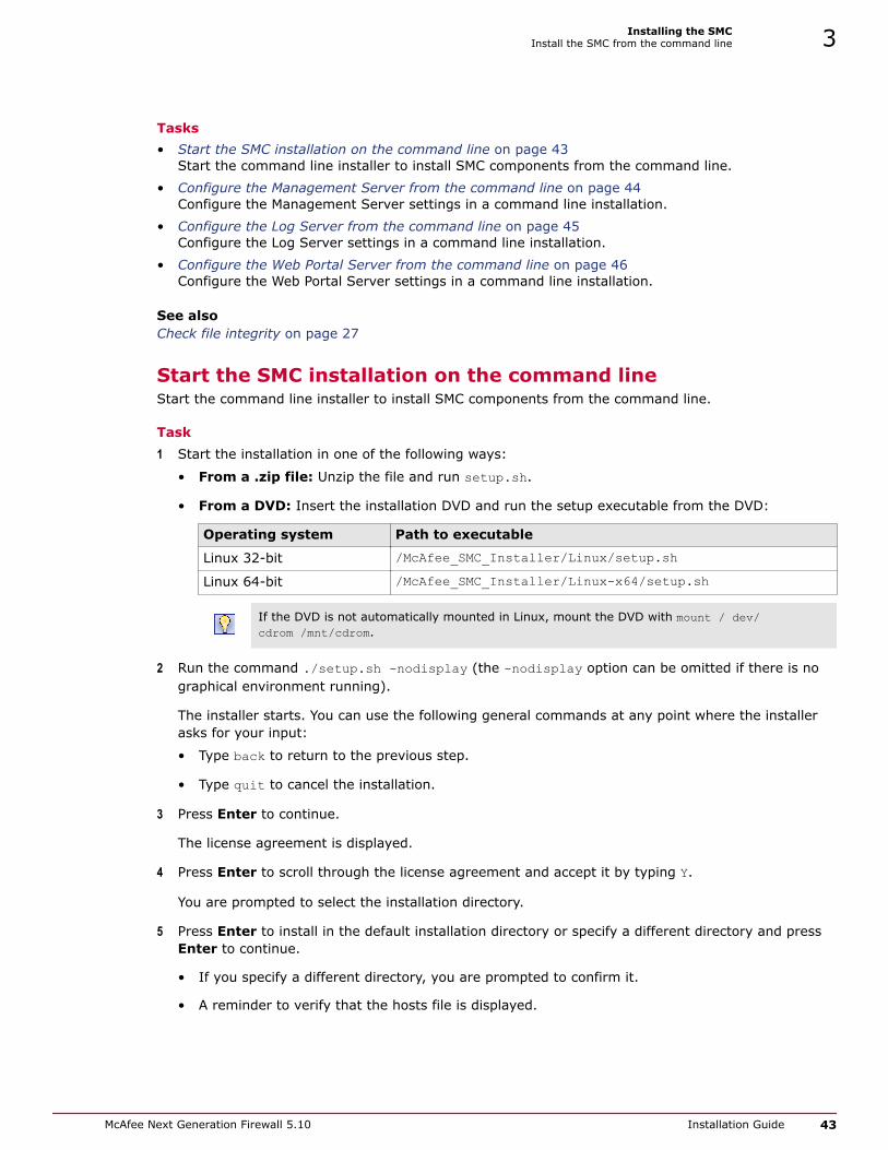
Tasks• Start the SMC installation on the command line on page 43
Start the command line installer to install SMC components from the command line.
• Configure the Management Server from the command line on page 44Configure the Management Server settings in a command line installation.
• Configure the Log Server from the command line on page 45Configure the Log Server settings in a command line installation.
• Configure the Web Portal Server from the command line on page 46Configure the Web Portal Server settings in a command line installation.
See also Check file integrity on page 27
Start the SMC installation on the command lineStart the command line installer to install SMC components from the command line.
Task1 Start the installation in one of the following ways:
• From a .zip file: Unzip the file and run setup.sh.
• From a DVD: Insert the installation DVD and run the setup executable from the DVD:
Operating system Path to executable
Linux 32-bit /McAfee_SMC_Installer/Linux/setup.shLinux 64-bit /McAfee_SMC_Installer/Linux-x64/setup.sh
If the DVD is not automatically mounted in Linux, mount the DVD with mount / dev/cdrom /mnt/cdrom.
2 Run the command ./setup.sh -nodisplay (the -nodisplay option can be omitted if there is nographical environment running).
The installer starts. You can use the following general commands at any point where the installerasks for your input:
• Type back to return to the previous step.
• Type quit to cancel the installation.
3 Press Enter to continue.
The license agreement is displayed.
4 Press Enter to scroll through the license agreement and accept it by typing Y.
You are prompted to select the installation directory.
5 Press Enter to install in the default installation directory or specify a different directory and pressEnter to continue.
• If you specify a different directory, you are prompted to confirm it.
• A reminder to verify that the hosts file is displayed.
Installing the SMCInstall the SMC from the command line 3
McAfee Next Generation Firewall 5.10 Installation Guide 43

6 Press Enter to continue.
You are prompted to select the link location for shortcuts to the most commonly usedcommand-line tools.
7 Press Enter to create links in the default directory or select one of the other options and pressEnter to continue.
You are prompted to select the type of installation.
8 Select the Install Set:
Option Description
Press Enter Installs all Security Management Center components except the WebPortal Server.
Press 2 and press Enter Installs only the Management Client.
Press 3 and press Enter Installs a simulated network environment for evaluation in Demo Mode.
Press 4 and press Enter Installs a custom selection of components.
9 (Customized installation only) Type a comma-separated list of numbers for the components youwant to select or deselect and press Enter.
• Entering the number of a selected component deselects it.
• Entering the number of a component that is not selected selects it.
• By default, the Management Server, Log Server, and Management Client are selected.
Example: To install only the Web Portal Server, type 1,2,3,4 and press Enter.
You are prompted to review and confirm the component selection.
10 Press Enter to continue.
Configure the Management Server from the command lineConfigure the Management Server settings in a command line installation.
Task1 Press Enter to use the default IP address for the Management Server or enter a different IP
address and press Enter to continue.
You are prompted to enter the IP address of the Log Server to which the Management Server sendsits log data.
2 Press Enter to use the default IP address for the Log Server or enter a different IP address andpress Enter to continue.
You are prompted to select whether to install the Management Server as an extra ManagementServer for high availability.
3 Type Y to install the Management Server as an extra Management Server for high availability or Nto install the Management Server as a standalone Management Server.
4 Press Enter to continue.
You are prompted to select whether to enable and configure a Web Start Server.
5 Type Y to enable and configure Web Start or type N.
3 Installing the SMCInstall the SMC from the command line
44 McAfee Next Generation Firewall 5.10 Installation Guide
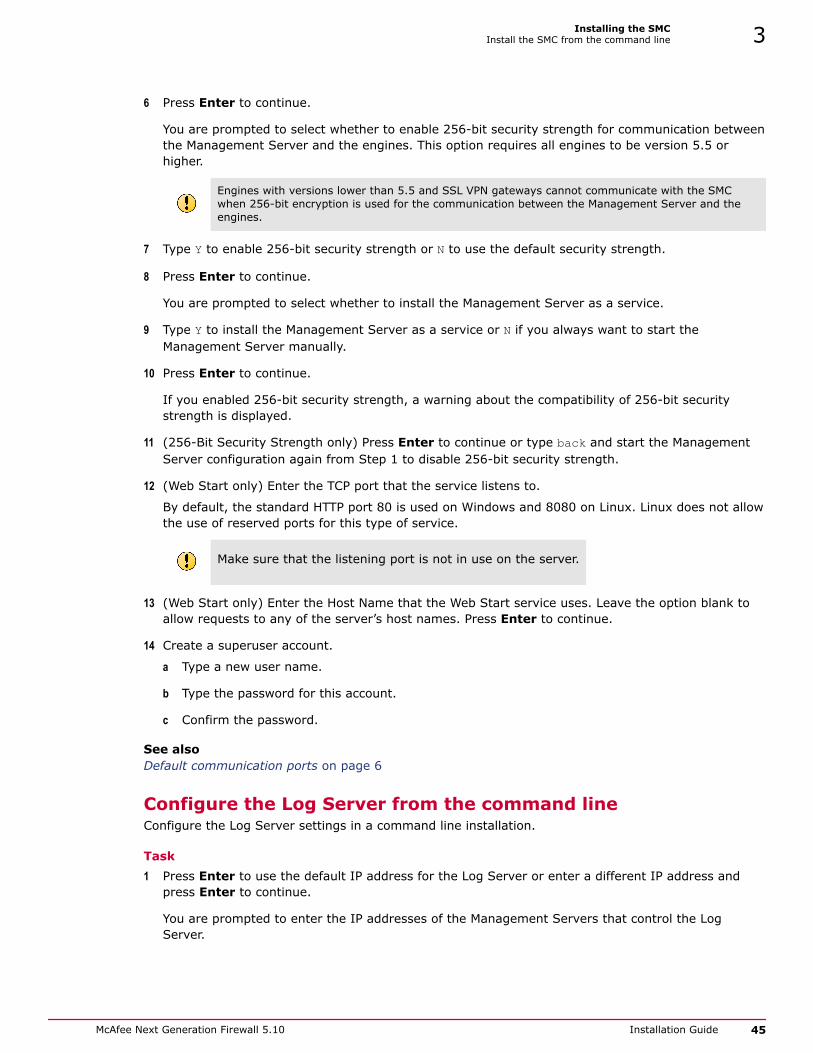
6 Press Enter to continue.
You are prompted to select whether to enable 256-bit security strength for communication betweenthe Management Server and the engines. This option requires all engines to be version 5.5 orhigher.
Engines with versions lower than 5.5 and SSL VPN gateways cannot communicate with the SMCwhen 256-bit encryption is used for the communication between the Management Server and theengines.
7 Type Y to enable 256-bit security strength or N to use the default security strength.
8 Press Enter to continue.
You are prompted to select whether to install the Management Server as a service.
9 Type Y to install the Management Server as a service or N if you always want to start theManagement Server manually.
10 Press Enter to continue.
If you enabled 256-bit security strength, a warning about the compatibility of 256-bit securitystrength is displayed.
11 (256-Bit Security Strength only) Press Enter to continue or type back and start the ManagementServer configuration again from Step 1 to disable 256-bit security strength.
12 (Web Start only) Enter the TCP port that the service listens to.
By default, the standard HTTP port 80 is used on Windows and 8080 on Linux. Linux does not allowthe use of reserved ports for this type of service.
Make sure that the listening port is not in use on the server.
13 (Web Start only) Enter the Host Name that the Web Start service uses. Leave the option blank toallow requests to any of the server’s host names. Press Enter to continue.
14 Create a superuser account.
a Type a new user name.
b Type the password for this account.
c Confirm the password.
See also Default communication ports on page 6
Configure the Log Server from the command lineConfigure the Log Server settings in a command line installation.
Task1 Press Enter to use the default IP address for the Log Server or enter a different IP address and
press Enter to continue.
You are prompted to enter the IP addresses of the Management Servers that control the LogServer.
Installing the SMCInstall the SMC from the command line 3
McAfee Next Generation Firewall 5.10 Installation Guide 45

2 Press Enter to use the default IP address for the Management Server or enter different IPaddresses and press Enter to continue.
You are prompted to enter the port on which the Log Server receives data.
3 Press Enter to use the default port or enter a different port and press Enter to continue.
You are prompted to select whether to install the Log Server as a service.
4 Type Y to install the Log Server as a service or N if you always want to start the Log Servermanually.
5 Press Enter to continue.
You are prompted to select the directory for log files.
6 Press Enter to use the default directory or specify a different directory and press Enter tocontinue.
Configure the Web Portal Server from the command lineConfigure the Web Portal Server settings in a command line installation.
Task1 Press Enter to use the default IP address for the Web Portal Server or enter a different IP address
and press Enter to continue.
You are prompted to enter the IP addresses of the Management Servers that control the Web PortalServer.
2 Press Enter to use the default IP address for the Management Server or enter different IPaddresses and press Enter to continue.
You are prompted to enter the IP address of the Log Server.
3 Press Enter to use the default IP address for the Log Server or enter a different IP address andpress Enter to continue.
You are prompted to select whether to install the Web Portal Server as a service.
4 Type Y to install the Web Portal Server as a service or N if you always want to start the Web PortalServer manually.
5 Press Enter to continue.
Install the SMC ApplianceThe SMC Appliance ships with the Management Server and a Log Server pre-installed on it. Startingthe appliance initiates an installation wizard.
Before you beginPrepare the appliance for installation:
• Determine the appliance networking information:
• IPv4 network address
• IPv4 network mask
3 Installing the SMCInstall the SMC Appliance
46 McAfee Next Generation Firewall 5.10 Installation Guide

• (Optional) Default gateway address
• (Optional) DNS server addresses
• Mount the appliance in a rack.
• Connect the network and console cables.
• Access the appliance through a KVM or the Remote Management Module port.
See the McAfee Security Management Center Appliance Hardware Guide for completedetails.
Task1 Turn on the SMC Appliance and accept the EULA.
2 Enter the account name and password.
The password must be ten characters and contain at least one number. The account name andpassword become an administrator account with unrestricted permissions (superuser) on theManagement Server.
a Enter the account name.
This field is case sensitive and limited to eight characters.
b Enter the password.
The password is case sensitive and must have a minimum of nine characters.
c Enter the password again.
3 Make your security selections.
a Specify if the appliance runs in FIPS 140-2 mode.
No is the default.
This option is for environments that are required to follow the FIPS 140-2 standards.
b Specify if the appliance uses 256-bit security strength.
Yes is the default.
The security strength is for the connection to the McAfee NGFW engines. The engines must alsouse 256-bit security strength.
4 Complete the network interface and network setup fields.
a Select the main network interface for management.
b Complete the network setup fields for the interface.
5 Enter a host name for the Management Server.
6 (Optional) Configure NTP settings.
When the installation is complete, the appliance restarts.
See also Contact the Management Server on page 137
Installing the SMCInstall the SMC Appliance 3
McAfee Next Generation Firewall 5.10 Installation Guide 47

Start the SMC after installationProceed through the listed sections in sequence to start the SMC for the first time.
Tasks• Log on to the SMC on page 49
The Management Client connects to the Management Server and to Log Servers.
• Accept the Management Server certificate on page 49A certificate dialog box is displayed when the Management Client contacts any ManagementServer for the first time.
• Install licenses for SMC servers on page 49Install the SMC server licenses that you downloaded while preparing for installation.
• Bind Management Server POL-bound licenses to servers on page 50You must bind Management Server POL-bound licenses for Log Servers and Web PortalServers to specific Server elements.
• Generate SMC server certificates on page 51If necessary, you can manually certify an SMC server or generate an SMC server certificate.
Start the Management ServerIf the Management Server does not start automatically, you must start it.
If the Management Server has been installed as a service, it starts automatically both after theinstallation and during the operating system boot process. In Windows, the McAfee NGFWManagement Server service is controlled in the Services window. That window is in the WindowsControl Panel under the Administrative Tools category.
Task
• Start the Management Server manually.
• In Windows, use the shortcut icon in the location you selected during installation or run thescript <installation directory>/bin/sgStartMgtSrv.bat.
• In Linux, run the script <installation directory>/bin/sgStartMgtSrv.sh.
When the Management Server has successfully started, you are ready to start the Management Client.
Start the Management ClientAfter you start the Management Server, start the Management Client
Task
1 To start a locally installed Management Client, use the appropriate step.
• In Windows, use the shortcut icon in the location you selected during installation or run thescript <installation directory>/bin/sgClient.bat.
• In Linux, run the script <installation directory>/bin/sgClient.sh. A graphicalenvironment is needed for the Management Client.
2 To start a Management Client using Web Start, follow these steps.
a In a web browser, enter http://<server address>:<port>.
:<port> is only needed if the server is configured to run on a different port from the HTTPstandard port 80.
b Click the link for the Web Start Management Client.
3 Installing the SMCStart the SMC after installation
48 McAfee Next Generation Firewall 5.10 Installation Guide
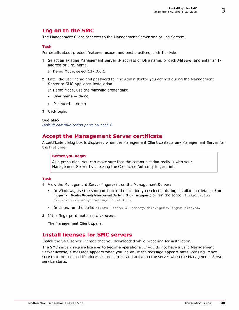
Log on to the SMCThe Management Client connects to the Management Server and to Log Servers.
TaskFor details about product features, usage, and best practices, click ? or Help.
1 Select an existing Management Server IP address or DNS name, or click Add Server and enter an IPaddress or DNS name.
In Demo Mode, select 127.0.0.1.
2 Enter the user name and password for the Administrator you defined during the ManagementServer or SMC Appliance installation.
In Demo Mode, use the following credentials:
• User name — demo
• Password — demo
3 Click Log in.
See also Default communication ports on page 6
Accept the Management Server certificateA certificate dialog box is displayed when the Management Client contacts any Management Server forthe first time.
Before you beginAs a precaution, you can make sure that the communication really is with yourManagement Server by checking the Certificate Authority fingerprint.
Task1 View the Management Server fingerprint on the Management Server:
• In Windows, use the shortcut icon in the location you selected during installation (default: Start |Programs | McAfee Security Management Center | Show Fingerprint) or run the script <installationdirectory>/bin/sgShowFingerPrint.bat.
• In Linux, run the script <installation directory>/bin/sgShowFingerPrint.sh.
2 If the fingerprint matches, click Accept.
The Management Client opens.
Install licenses for SMC serversInstall the SMC server licenses that you downloaded while preparing for installation.
The SMC servers require licenses to become operational. If you do not have a valid ManagementServer license, a message appears when you log on. If the message appears after licensing, makesure that the licensed IP addresses are correct and active on the server when the Management Serverservice starts.
Installing the SMCStart the SMC after installation 3
McAfee Next Generation Firewall 5.10 Installation Guide 49

TaskFor details about product features, usage, and best practices, click ? or Help.
1 In the Management Client, install licenses through the License Information message.
a Click Continue.
A dialog box opens.
b Select the license files in the dialog box.
If the message is not shown, install the licenses as explained in the next step. Otherwise, checkthat the licenses were installed correctly.
2 If you are not prompted to install a Management Server license, install the license files for theother SMC servers.
a Select File | System Tools | Install Licenses.
A file browser dialog box opens.
b Select the license files and click Install.
3 Check that the licenses were installed correctly.
a Select Configuration | Configuration | Administration.
The Administration Configuration view opens.
b Expand the Licenses branch and select All Licenses.
c Check that all licenses you installed are listed here.
See also Obtain license files on page 28
Bind Management Server POL-bound licenses to serversYou must bind Management Server POL-bound licenses for Log Servers and Web Portal Servers tospecific Server elements.
Task1 Select Configuration | Configuration | Administration.
The Administration Configuration view opens.
2 Browse to Licenses | Servers.
Installed licenses appear in the right pane.
3 Right-click a Management Server POL-bound license.
The Select License Binding dialog box opens.
3 Installing the SMCStart the SMC after installation
50 McAfee Next Generation Firewall 5.10 Installation Guide

4 Select the correct server from the list.
5 Click Select.
If you bound the license to an incorrect element, right-click the license and select Unbind.
The license is now bound to the selected Log Server or Web Portal Server element.
The license is permanently bound to the Log Server or Web Portal Server element when the server isstarted for the first time. A permanently bound license cannot be rebound to a different Log Server orWeb Portal Server element without relicensing or deleting the element that the license is bound to. Untilyou do that, the unbound license is shown as Retained.
Start SMC serversIf the Log Server and optional Web Portal Server do not start automatically, you must start them.
If the Log Server and Web Portal Server have been installed as a service, the servers are startedautomatically during the operating system boot process. If the operating system is restarted and theservers do not yet have a license, you might need to start them manually.
Task1 Start the Log Server and the optional Web Portal Server.
• If you installed the Log Server or Web Portal Server as a service, start or stop the servermanually in Windows through the Services window.
• Start the Log Server or Web Portal Server manually by running scripts in a console window.
Read the console messages for information about the progress. Closing the console stops theservice.
Server type Windows script Linux script
Log Server <installation directory>/bin/sgStartLogSrv.bat
<installation directory>/bin/sgStartLogSrv.sh
Web PortalServer
<installation directory>/bin/sgStartWebPortalServer.bat
<installation directory>/bin/sgStartWebPortalServer.sh
2 If the Log Server or Web Portal Server does not start, troubleshoot and resolve issues that causestarting to fail.
• Try starting the server by running scripts in a console window to see if an error is displayed onthe console.
• Check that licenses are correctly bound to components.
• Make sure that the server has a valid certificate for secure system communications. If there arecertificate-related problems or problems you are not able to identify, try regenerating thecertificate.
Generate SMC server certificatesIf necessary, you can manually certify an SMC server or generate an SMC server certificate.
To manually certify an SMC server, run one of the following scripts in Windows or in Linux dependingon the server type:
Installing the SMCStart the SMC after installation 3
McAfee Next Generation Firewall 5.10 Installation Guide 51

Server type Windows script Linux script
Log Server <installation directory>/bin/sgCertifyLogSrv.bat
<installation directory>/bin/sgCertifyLogSrv.sh
Web PortalServer
<installation directory>/bin/sgCertifyWebPortalServer.bat
<installation directory>/bin/sgCertifyWebPortalServer.sh
To generate a server certificate, follow these steps:
Task1 Enter the user name and password for the account you created during the Management Server
installation (other accounts with unrestricted permissions can also be used).
2 Click Accept to accept the certificate fingerprint of the Management Server’s Certificate Authority. Asa precaution, you can make sure that the communication really is with your Management Server.
The Server Selection dialog box opens.
3 Identify the component that you want to certify:
• If the server element that represents the component is listed, select it.
• If recommended follows the name of a server element, the component ID of the server elementmatches the ID of the component that you are certifying. It is suggested that you select therecommended server element.
Selecting a server element that is not the recommended server element might cause seriousproblems. For example, the server’s log data or the monitoring status of the server might bedisplayed incorrectly.
• If the correct server element is not listed, select Create a New Log Server or Create a New Web Portal Serverand enter a name in the Name field.
4 Click OK.
Post-installation SMC configurationsAfter installation, you can configure settings for system communication and add more functions to theSMC.
• If NAT is applied to communications between any SMC components, configure NAT addresses forSMC components.
• If you want to install high availability Management Servers, configure and install more ManagementServers.
• If you want to enable Web Start or you want to change the Web Start Server settings, distributeManagement Clients through Web Start.
When you are finished configuring the SMC, you are ready to use the Management Client to configureFirewall, IPS, and Layer 2 Firewall elements. The elements must be configured before installing thephysical engines.
See also Configuring NAT addresses for SMC components on page 53Add Management Servers for high availability on page 56Distribute Management Clients through Web Start on page 57
3 Installing the SMCPost-installation SMC configurations
52 McAfee Next Generation Firewall 5.10 Installation Guide

4 Configuring the SMC
After initial installation is complete, configure the SMC to allow adding the other components for yoursystem.
Contents Configuring NAT addresses for SMC components Add Management Servers for high availability Distribute Management Clients through Web Start
Configuring NAT addresses for SMC componentsYou must configure Locations and contact addresses when network address translation (NAT) isapplied to the communications between any of the SMC components.
If there is NAT between communicating SMC components, the translated IP address might have to bedefined for system communications.
You use Location elements to configure SMC components for NAT. There is a Default Location to whichall elements belong if you do not assign them to a specific Location. If NAT is applied between twoSMC components, you must separate them into different Locations and then add a contact address forthe component to be contacted.
You can define a Default contact address for contacting an SMC component (defined in the Propertiesdialog box of the corresponding element). The component’s Default contact address is used incommunications when SMC components that belong to another Location contact the component andthe component has no contact address defined for its Location.
Figure 4-1 Example scenario—using locations
Component Description
Headquarters Location
1 Management/Log server
4
McAfee Next Generation Firewall 5.10 Installation Guide 53

Component Description
2 Internet
3 IPS
4 Firewall
Between locations
5 Internet
Branch Office Location
6 Firewall
7 IPS
8 Internet
In the example scenario above, the same Management Server and Log Server manage SMCcomponents both at a company’s headquarters and at the branch office.
NAT could typically be applied at the following points:
• The firewall at the headquarters or an external router can provide the SMC servers external IPaddresses on the Internet. The external addresses must be defined as contact addresses so thatthe SMC components at the branch offices can contact the servers across the Internet.
• The branch office firewall or an external router can provide external addresses for the SMCcomponents at the branch office. In this case, the external IP addresses must also be defined ascontact addresses so that the Management Server can contact the components.
When contact addresses are needed, it might be enough to define a single new Location element, forexample, for the branch office, and to group the SMC components at the branch office into the“Branch Office” Location. The same Location element could also be used to group SMC components atany other branch office when they connect to the SMC servers at the headquarters.
To be able to view logs, the administrators at the branch office must select the “Branch Office”Location in the Management Client.
Configuration overview
1 Define Location elements.
2 Define contact addresses for the Management Servers and Log Servers.
3 Select the Location for your Management Client.
4 Select the Locations for McAfee NGFW engines when you create the engine elements.
See also Default communication ports on page 6
Add Location elementsGroup the SMC components into Location elements based on which components are on the same side ofa NAT device.
The elements that belong to the same Location element always use the primary IP address whencontacting each other.
4 Configuring the SMCConfiguring NAT addresses for SMC components
54 McAfee Next Generation Firewall 5.10 Installation Guide

Task1 Select Configuration | Configuration | Administration.
2 Expand the Other Elements branch.
3 Right-click Locations and select New Location.
4 In the Name field, enter a name.
5 Select elements from the Resources pane and click Add.
6 Click OK.
If your Management Server or Log Server needs a contact address, add SMC server contact addresses.
Otherwise, you are ready to configure the Firewall, IPS, and Layer 2 Firewall elements in the ManagementClient. You must configure the elements before configuring the McAfee NGFW engine software.
Add SMC Server contact addressesThe Management Server and Log Server can have more than one contact address for each Location.
• If you have additional Management Servers or Log Servers, define two or more contact addressesfor each Location. Multiple contact addresses are required so that remote components can connectto a Management Server or a Log Server even if one of the Management Servers or Log Serversfails.
• If you have configured Multi-Link, define two or more contact addresses per Location so thatremote components can connect to the servers even if a NetLink goes down.
Task1 Right-click a server and select Properties.
2 From the Location drop-down menu, select the location to which the server belongs.
3 If necessary, edit the contact addresses.
• A Default contact address is automatically entered based on the element properties.
• If the server has multiple Default contact addresses, separate the addresses with commas.
• If necessary, click Exceptions to define other contact addresses for specific Locations
Elements that belong to the same Location element always use the primary IP address whencontacting each other instead of any contact addresses. Elements that do not belong to a specificLocation are considered to belong to the Default Location.
4 Click OK.
Set the Management Client locationWhen there is a NAT device between the Management Client and a Log Server, select the correctLocation for your Management Client. Make the selection in the status bar at the bottom of theManagement Client window to be able to view logs.
You must select the Management Client Location separately in each administrative Domain if there aremultiple Domains in your environment.
Configuring the SMCConfiguring NAT addresses for SMC components 4
McAfee Next Generation Firewall 5.10 Installation Guide 55

TaskFor details about product features, usage, and best practices, click ? or Help.
1 In the Management Client, click the Default Location name in the status bar at the bottom of thewindow.
2 Select the Location that includes the IP address or network of the computer where you use theManagement Client.
Add Management Servers for high availabilityYou can optionally install one or more additional Management Servers for high availability.
Additional Management Servers control the system if the active Management Server is damaged, losespower, or becomes otherwise unusable. Configuration data is automatically replicated between theManagement Servers. Only one Management Server at a time can be used as an active ManagementServer to configure and manage the system.
To use additional Management Servers, you must have a special Management Server license that liststhe IP addresses of all Management Servers within the same SMC.
You must install the license in the Management Client before installing the additional ManagementServers. If you do not yet have the license, generate the license at the McAfee website after receivingthe Proof-of-License, then install the license.
Perform this task for each Management Server that you want to add.
Task1 Start the installation in one of the following ways:
• From a .zip file: Unzip the file and run setup.exe on Windows or setup.sh on Linux.
• From a DVD: Insert the installation DVD and run the setup executable from the DVD:
Operating system Path to executable
Windows 64-bit \McAfee_SMC_Installer\Windows-x64\setup.exeLinux 32-bit /McAfee_SMC_Installer/Linux/setup.shLinux 64-bit /McAfee_SMC_Installer/Linux-x64/setup.sh
If the DVD is not automatically mounted in Linux, mount the DVD with mount / dev/cdrom /mnt/cdrom.
2 Proceed according to the instructions in the Installation Wizard until you are prompted to selectwhich components you want to install.
We do not recommend selecting C:\Program Files\McAfee\Security Management Center as theinstallation directory in Windows. Selecting C:\Program Files\McAfee\Security Management Centeras the installation directory creates an extra C:\ProgramData\McAfee\Security Management Centerfolder, which duplicates some of the folders in the installation directory. Some of the program data isalso stored in the C:\ProgramData\McAfee\Security Management Center folder.
4 Configuring the SMCAdd Management Servers for high availability
56 McAfee Next Generation Firewall 5.10 Installation Guide

3 Select the installation type.
• If you want to install a Log Server and a local Management Client on this computer, leave Typicalselected and click Next.
• If you only want to install a Management Server on this computer, select Custom, select thecomponents you want to install and click Next.
4 Select the IP address of the Management Server from the list or type it in.
• This address must be the IP address defined for the corresponding Management Serverelement.
• The Management Server’s license must be generated using this IP address.
5 Enter the IP address of the Log Server to which the Management Server sends its log data.
6 Select Install as an Additional Management Server for High Availability.
7 To make the Management Server start automatically, leave Install as a Service selected.
8 Click Next and follow the instructions to start the installation.
A logon prompt for Replication opens.
9 Log on using an unrestricted administrator account.
The Management Server Selection dialog opens.
10 Select the correct Management Server from the list or select Create a new Management Server and enterthe name of the Management Server element you are creating.
11 Click OK.
The databases are synchronized.
If the synchronization fails, run the sgOnlineReplication script on the additional ManagementServer when connectivity is restored.
You can now use the Management Client to configure the Firewall, IPS, and Layer 2 Firewall elementsin the Management Client. The elements must be configured before installing the physical engines.
If NAT is applied to communications between any SMC components, configure NAT addresses for SMCcomponents.
If there is a Firewall or Layer 2 Firewall between the first Management Server you installed and theadditional Management Servers, add rules that allow the communications between the servers whenyou define your Firewall or Layer 2 Firewall Policy.
See also Install licenses for SMC servers on page 49Install SMC components on page 36
Distribute Management Clients through Web StartIn addition to installing Management Clients on a local workstation, you can also distribute themthrough Java Web Start.
Management Clients distributed with Web Start have the same set of features as clients installed on alocal workstation. However, when you upgrade, Web Start automatically downloads the new versionwhen the user logs on to the Management Client through a web browser.
Configuring the SMCDistribute Management Clients through Web Start 4
McAfee Next Generation Firewall 5.10 Installation Guide 57

There are two ways to configure Web Start access:
• You can activate an internal web server on the Management Server (the server distributes onlyWeb Start Management Clients). There is no need for manual installation or upgrade.
• You can use a separate web server or network drive for distributing the clients. You must installWeb Start files manually and reinstall them at each SMC version upgrade.
Tasks• Distribute Management Clients from SMC servers on page 58
You can configure a Web Start Server to distribute Management Clients from theManagement Server. If you have already configured the Web Start Server, you canconfigure additional settings.
• Distribute Management Clients from a separate server on page 59If you want to use a Web Start Server to distribute Management Clients, but you don'twant to use the Management Server as a Web Start Server, you can install the Web StartServer on a separate server.
Distribute Management Clients from SMC serversYou can configure a Web Start Server to distribute Management Clients from the Management Server.If you have already configured the Web Start Server, you can configure additional settings.
TaskFor details about product features, usage, and best practices, click ? or Help.
1 In the Management Client, select Monitoring | System Status.
The System Status view opens.
2 Expand the Servers branch.
3 Right-click a Management Server and select Properties.
The Properties dialog box opens.
4 Click the Web Start tab.
5 Select Enable.
The Web Start Server options are enabled.
6 (Optional) Enter the Host Name that the Web Start service uses.
7 (Optional) Enter the TCP port that the service listens to.
By default, the standard HTTP port 80 is used on Windows and 8080 on Linux. Linux does not allowthe use of reserved ports for this type of service.
Make sure that the listening port is not in use on the server.
8 (Optional) If the Management Server has several addresses and you want to restrict access to oneaddress, specify the IP address in the Listen Only on Address field.
9 (Optional) Select Generate Server Logs if you want to log all file load events for further analysis withexternal web statistics software.
10 Click OK.
See also Default communication ports on page 6
4 Configuring the SMCDistribute Management Clients through Web Start
58 McAfee Next Generation Firewall 5.10 Installation Guide

Distribute Management Clients from a separate serverIf you want to use a Web Start Server to distribute Management Clients, but you don't want to use theManagement Server as a Web Start Server, you can install the Web Start Server on a separate server.
The Web Start package can also be put on a shared network drive. The path to the Web Start files,including the drive letter, must be the same for all administrators who use that particular version ofthe installation package. If the network drive paths vary, consider putting the package on a webserver instead.
You must delete the existing Web Start files and install a new Web Start package according to theseinstructions each time you upgrade the SMC. Otherwise, any administrators who use ManagementClients that are installed through Web Start are not able to log on.
Task1 On the installation DVD, browse to McAfee_SMC_Installer | Webstart.
The Web Start installation creates an index.html file in the installation directory. Anyexisting index.html file is overwritten. We strongly recommend creating a directory forthe Web Start files.
2 Copy all files and all directories from the Web Start directory on the installation DVD to thedirectory where you want the Web Start files to be served.
3 On the command line, change to the directory where the Web Start files are on your server.
4 Run the Web Start setup script and give the URL or the path of the directory where the Web Startfiles are stored on your server:
• Windows: cscript webstart_setup.vbs <web start directory>
• Linux: Run webstart_setup.sh <web start directory>
Installation on Example Web Start directory
Web server http://www.example.com/webstart/
Network drive file://localhost/c:/webstart/
5 If necessary, change the configuration of the web server to return the appropriate MIME typefor .jnlp files (application/x-java-jnlp-file).
See the manual of your web server for instructions on how to configure the MIME type.
6 Delete the webstart_setup.vbs and webstart_setup.sh files from the directory.
Configuring the SMCDistribute Management Clients through Web Start 4
McAfee Next Generation Firewall 5.10 Installation Guide 59

4 Configuring the SMCDistribute Management Clients through Web Start
60 McAfee Next Generation Firewall 5.10 Installation Guide

McAfee NGFW enginedeploymentMcAfee NGFW engine deployment consists of adding and configuring engineelements in the SMC, and configuring the McAfee NGFW software on theengine.
Chapter 5 Configuring McAfee NGFW for the Firewall/VPN roleChapter 6 Configuring McAfee NGFW for the IPS roleChapter 7 Configuring McAfee NGFW for the Layer 2 Firewall roleChapter 8 Configuring McAfee NGFW engines as Master Engines and Virtual Security
EnginesChapter 9 Configuring McAfee NGFW engine softwareChapter 10 McAfee NGFW engine post-installation tasks
McAfee Next Generation Firewall 5.10 Installation Guide 61

McAfee NGFW engine deployment
62 McAfee Next Generation Firewall 5.10 Installation Guide

5 Configuring McAfee NGFW for theFirewall/VPN role
Configuring engine elements in the SMC prepares the SMC to manage McAfee NGFW engines in theFirewall/VPN role.
Contents Install licenses for McAfee NGFW engines Configuring Single Firewalls Configuring Firewall Clusters
Install licenses for McAfee NGFW enginesInstall the McAfee NGFW engine licenses that you downloaded while preparing for installation.
Before you beginThe license files must be available to the computer that you use to run the ManagementClient.
You can install all licenses at the same time even though you have not yet created all elements thatthe licenses are bound to.
TaskFor details about product features, usage, and best practices, click ? or Help.
1 In the Management Client, select File | System Tools | Install Licenses.
2 Select one or more license files to install in the dialog box that opens and click Install.
3 Check that licenses were installed correctly.
a Select Configuration | Configuration | Administration.
The Administration Configuration view opens.
b Expand the Licenses branch of the tree.
c Select All Licenses in the list.
One license shows for each McAfee NGFW engine node. You must bind POL-bound engine licensesmanually to the correct engines after you have configured the engine elements. POS-bound enginelicenses are automatically attached to the correct engines after the engine is fully installed.
You are ready to define the engine elements.
5
McAfee Next Generation Firewall 5.10 Installation Guide 63

See also Types of licenses for McAfee NGFW engines on page 28Configuring Single Firewalls on page 64Configuring Firewall Clusters on page 77
Configuring Single FirewallsAfter you have the SMC installed and running, you can configure the Single Firewall elements.
Little configuration is done directly on the engines. Most of the configuration is done using theManagement Client. The engines cannot be successfully installed before defining them in theManagement Client.
The tasks you must complete are as follows:
1 Add Single Firewall elements.
2 Add interfaces and define their properties.
3 (Optional) Select system communication roles for the interfaces.
4 Bind Management Server POL-bound licenses to specific Single Firewall elements.
Types of interfaces for Single FirewallsInterface numbers identify the interfaces for a Single Firewall element.
You can configure the following types of interfaces on Single Firewalls:
Table 5-1 Interface types for Single Firewalls
Interfacetype
Description SMC numbering
Physicalinterface
Represents an Ethernet port of a networkinterface card on the engine.
You can add VLAN interfaces to physicalinterfaces to divide a single physicalnetwork link into several virtual links.
Each physical interface has a uniqueinterface ID number in the SMC.
ADSLinterface
Represents the ADSL port of a purpose-builtMcAfee NGFW appliance.
Only certain McAfee NGFW applianceshave an integrated ADSL networkinterface card with an ADSL port.
Each ADSL interface has a uniqueinterface ID number in the SMC.
Wirelessinterface
Represents a wireless network interfacecard of a purpose-built McAfee NGFWappliance.
Only certain McAfee NGFW applianceshave an integrated wireless networkinterface card.
The wireless interface has a uniqueinterface ID number in the SMC.An SSID (service set identifier)interface represents an 802.11 wirelessLAN. You can add several SSIDinterfaces to the wireless interface.
5 Configuring McAfee NGFW for the Firewall/VPN roleConfiguring Single Firewalls
64 McAfee Next Generation Firewall 5.10 Installation Guide

Table 5-1 Interface types for Single Firewalls (continued)
Interfacetype
Description SMC numbering
Modeminterface
Represents a 3G modem connected to aUSB port on a purpose-built McAfee NGFWappliance.
Modem Interfaces are identified withmodem numbers in the SMC.The modem number is mapped to themodem’s IMEI (international mobileequipment identity) number.
Each modem is assigned a unique IDwhen you connect the modem to theSingle Firewall engine.
Tunnelinterface
A logical interface that is used as anendpoint for tunnels in the Route-BasedVPN.
For detailed information aboutconfiguring tunnel interfaces and theRoute-Based VPN, see the McAfee NextGeneration Firewall Product Guide.
Tunnel interfaces are numbered withtunnel interface ID numbers. Thetunnel interface IDs are automaticallymapped to the network interfaces onthe engine according to the routingconfiguration.
Integratedswitch
Represents the switch functionality on apurpose-built McAfee NGFW appliance.
Only certain McAfee NGFW applianceshave an integrated switch.
Integrated switches are identified withIDs in the SMC.You can add port group interfaces toswitches. Port group interfaces areidentified by port group IDs.
The modem numbers, switch IDs, and interface IDs are mapped to the corresponding networkinterfaces on the engine when you configure the McAfee NGFW engine software. Check the correctinterface numbers in the Hardware Guide for your appliance model.
If you configure the engine automatically with a USB drive, the interface IDs in the SMC are mapped tomatch the interface numbering in the operating system. For example, eth0 is mapped to Interface ID 0.
If necessary, you can change the interface ID, switch ID, and modem number mapping after the initialconfiguration using the command-line tools on the engine.
Add Single Firewall elementsTo add a single-node firewall to the SMC, add a Single Firewall element that stores the configurationinformation related to the firewall.
You can also define several Single Firewall elements at the same time by using the Create MultipleSingle Firewalls wizard. For more information about creating several Single Firewall elements at thesame time, see the McAfee Next Generation Firewall Product Guide.
TaskFor details about product features, usage, and best practices, click ? or Help.
1 Select Configuration | Configuration | Security Engine.
2 Right-click Security Engines and select New | Firewall | Single Firewall.
The Engine Editor opens.
3 In the Name field, enter a unique name.
4 From the Log Server drop-down list, select the Log Server for storing this firewall’s logs.
Configuring McAfee NGFW for the Firewall/VPN roleConfiguring Single Firewalls 5
McAfee Next Generation Firewall 5.10 Installation Guide 65

5 (Optional) In the DNS IP Addresses list, add one or more DNS IP addresses.
These addresses are the IP addresses of the DNS servers that the Single Firewall uses to resolvemalware signature mirrors, domain names, and web filtering categorization services. There are twoways to define IP addresses:
• To enter a single IP address manually, click Add and select IP Address. Enter the IP address in thedialog that opens.
• To define an IP address by using a network element, click Add and select Network Element. Select aHost or External DNS Server element from the dialog box that opens. Alternatively, click the Newicon and select Host or External DNS Server to define a new element.
6 From the Location drop-down list, select the Location to which the firewall belongs.
7 (Optional) If you have a McAfee NGFW appliance, copy and paste the proof-of-serial (POS) codedelivered with the appliance to the Proof of Serial field.
Using the POS code allows you to configure the Single Firewall engine using plug and playconfiguration.
8 Click the Save icon in the toolbar.
Do not close the Engine Editor.
See also Prepare for plug and play configuration on page 128
Add physical interfaces to Single FirewallsTo route traffic through the firewall, you must define at least two physical interfaces.
Only the interface that is used for communications between the Management Server and theFirewall/VPN engine is required when you install the Single Firewall. Although you can configure moreinterfaces at any time, it is recommended to add more interfaces right away.
There are three types of physical interfaces:
• An interface that corresponds to a single network interface on the firewall engine. In theManagement Client, the interface type is None.
• An aggregated link in high availability mode represents two interfaces on the firewall engine. Onlythe first interface in the aggregated link is actively used. The second interface becomes active onlyif the first interface fails.
Connect the first interface in the link to one external switch and the second interface to anotherexternal switch.
• An aggregated link in load balancing mode represents two or more interfaces (up to eightinterfaces) on the firewall engine. All interfaces in the aggregated link are actively used andconnections are automatically balanced between the interfaces.
Link aggregation in load-balancing mode is implemented based on the IEEE 802.3ad LinkAggregation standard. Connect all interfaces to a single external switch. Make sure that the switchsupports the Link Aggregation Control Protocol (LACP) and that LACP is configured on the switch.
Task1 In the navigation pane on the left, select Interfaces.
2 Right-click the empty space and select New | Physical Interface.
3 From the Interface ID drop-down list, select an ID number.
This ID maps to a network interface during the initial configuration of the engine.
5 Configuring McAfee NGFW for the Firewall/VPN roleConfiguring Single Firewalls
66 McAfee Next Generation Firewall 5.10 Installation Guide

4 From the Type drop-down list, select the interface type.
5 If the type is aggregated link, select one or more other interfaces that belong to the aggregatedlink.
• For an aggregated link in high availability mode, select an interface ID from the Second Interface IDdrop-down list.
• For an aggregated link in load balancing mode, click Add to add one or more interface IDs to theAdditional Interface(s) list.
6 Click OK.
7 Click the Save icon in the toolbar.
Do not close the Engine Editor.
The physical interface is added to the interface list.
Add VLAN interfaces to Single FirewallsVLANs divide a single physical network link into several virtual links.
You can add up to 4094 VLANS to each physical interface.
Task1 In the navigation pane on the left, select Interfaces.
2 Right-click a physical interface and select New | VLAN Interface.
3 In the VLAN ID field, enter a VLAN ID number (1-4094).
The VLAN ID must be the same VLAN ID used in the external switch at the other end of the VLANtrunk.
4 Click OK.
The specified VLAN ID is added to the physical interface.
5 Click the Save icon in the toolbar.
Do not close the Engine Editor.
The VLAN interface is now ready to be used as a network interface. The VLAN interface is identified asInterface-ID.VLAN-ID, for example 2.100 for interface ID 2 and VLAN ID 100.
Add ADSL Interfaces to Single FirewallsYou can add one ADSL interface to a Single Firewall.
ADSL is only supported on specific McAfee NGFW appliances that have an ADSL network interfacecard. The supported ADSL standards are ANSI T1.413 issue 2n, G.dmt, G.lite, ADSL2 DMT, ADSL2G.lite, Annex A, and Annex B.
TaskFor details about product features, usage, and best practices, click ? or Help.
1 In the navigation pane on the left, select Interfaces.
2 Right-click the empty space and select New | ADSL Interface.
Configuring McAfee NGFW for the Firewall/VPN roleConfiguring Single Firewalls 5
McAfee Next Generation Firewall 5.10 Installation Guide 67

3 From the Interface ID drop-down list, select the number of the ADSL port on the appliance as theInterface ID.
The Interface ID is automatically mapped to the ADSL port on the engine’s ADSL card during theinitial configuration of the engine.
4 In the VCI field, enter the VCI (Virtual Channel Identifier) value according to the configurationinformation provided by your ISP.
5 In the VPI field, enter the VPI (Virtual Path Identifier) value according to the configurationinformation provided by your ISP.
6 From the Multiplexing Mode drop-down list, select LLC (Logical Link Control) or VC (Virtual Circuit)according to the configuration information provided by your ISP.
7 Define the ADSL Interface properties.
Option Explanation
Interface ID Select the number of the ADSL port on the appliance as the Interface ID. TheInterface ID is automatically mapped to the ADSL port on the engine’s ADSL cardduring the initial configuration of the engine.
VCI Enter the VCI (Virtual Channel Identifier) value according to the configurationinformation provided by your ISP.
VPI Enter the VPI (Virtual Path Identifier) value according to the configurationinformation provided by your ISP
Multiplexing Mode Select LLC (Logical Link Control) or VC (Virtual Circuit) according to theconfiguration information provided by your ISP.
8 Click OK to close the ADSL Interface properties.
9 Click the Save icon in the toolbar.
Do not close the Engine Editor.
Add wireless interfaces to Single FirewallsYou can add one wireless interface to a Single Firewall.
Wireless interfaces are only supported on specific McAfee NGFW appliances that have an integratedwireless network interface card.
TaskFor details about product features, usage, and best practices, click ? or Help.
1 In the navigation pane on the left, select Interfaces.
2 Right-click the empty space and select New | Wireless Interface.
3 From the Interface ID drop-down list, select the interface ID number.
This ID number maps to the wireless port during the initial configuration of the engine.
4 In the Country field, enter or select the country where the firewall is used as a wireless access point.
5 From the Band drop-down list, select the band for the wireless interface access point.
5 Configuring McAfee NGFW for the Firewall/VPN roleConfiguring Single Firewalls
68 McAfee Next Generation Firewall 5.10 Installation Guide

6 From the Wireless Mode drop-down list, select the mode for transmitting the wireless traffic accordingto the capabilities of the connecting clients.
The wireless mode options that you can select depend on the band.
Band Wireless mode
2.4 GHz 802.11b
802.11bg
802.11g
802.11n
802.11bgn
5 GHz 802.11a
802.11an
802.11n
Some wireless clients do not support the 802.11n wireless mode with the WEP security mode.
7 From the Channel drop-down list, select the channel for transmitting the wireless traffic.
If there are other wireless access points nearby, use channels that are as far apart as possible toavoid interference.
8 (Optional) From the Transmit Power drop-down list, select the maximum power of the signal fortransmitting the wireless traffic.
• The power options are shown as milliwatts (mW) and as the power ratio in decibels of themeasured power referenced to 1 milliwatt (dBm).
• The values available depend on the regulatory limits for the selected country and the channelfor the wireless interface.
• If you are not sure what value to use, leave the default value selected.
9 Click OK.
The wireless interface is added to the interface list.
10 Click the Save icon in the toolbar.
Do not close the Engine Editor.
Add SSID Interfaces to Single FirewallsA service set identifier (SSID) interface represents an 802.11 wireless LAN.
You can add several SSID Interfaces to the Wireless Interface.
Task1 In the navigation pane on the left, select Interfaces.
2 Right-click the wireless interface and select New SSID Interface.
3 In the Wireless Network Name (SSID) field, enter the wireless network name.
It identifies the network to the end users.
Configuring McAfee NGFW for the Firewall/VPN roleConfiguring Single Firewalls 5
McAfee Next Generation Firewall 5.10 Installation Guide 69

4 From the Wireless SSID Broadcast drop-down list, select one of the following options:
• Enabled — The wireless network name is broadcast to anyone in range.
• Disabled — Users must type the name to connect.
5 From the MAC Address Type drop-down list, select one of the following options:
• Hardware — The first SSID Interface that you define is automatically assigned the MAC address ofthe wireless card.
• Custom — A custom MAC address.
6 (Custom MAC address only) In the MAC Address field, enter a MAC address.
7 Click the Security tab.
8 From the Security Mode drop-down list, select the security mode.
When you select the security mode, the options particular for that mode are enabled. Werecommend using one of the WPA security modes.
9 Fill in the options for the selected security mode:Mode Steps
WEP Open Systemand WEP SharedKey
1 From the Key Length drop-down list, select the key length.
2 From the Default Key drop-down list, select which key is used by default.
3 Enter 1–4 encryption keys.
WPA Personal 1 From the WPA Mode drop-down list, select the WPA mode.
2 In the Pre-Shared Key field, enter a pre-shared key of 8 to 64 ASCIIcharacters.
WPA Enterprise 1 From the WPA Mode drop-down list, select the WPA mode.
2 Next to the Authentication Method field, click Select.
3 Select the RADIUS authentication method for authenticating users and clickSelect.
10 Click OK.
11 Click the Save icon in the toolbar.
Do not close the Engine Editor.
Add Switches to Single FirewallsYou can add one integrated switch to a Single Firewall.
An integrated switch eliminates the need for an external switch device and simplifies port and networksegment configuration.
The switch functionality is only supported on Single Firewall engines that run on specific McAfee NGFWappliances that have an integrated switch.
5 Configuring McAfee NGFW for the Firewall/VPN roleConfiguring Single Firewalls
70 McAfee Next Generation Firewall 5.10 Installation Guide

TaskFor details about product features, usage, and best practices, click ? or Help.
1 In the navigation pane on the left, select Interfaces.
2 Right-click the empty space and select New | Switch.
3 From the Switch ID drop-down list, select the ID according to your switch type. For example, theswitch ID of the McAfee NGFW 110 appliance is 0. See the Hardware Guide for your appliance formore information.
4 From the Switch Type drop-down list, select the type of your McAfee NGFW switch.
5 Click OK.
6 Click the Save icon in the toolbar.
Do not close the Engine Editor.
You are now ready to add port group interfaces to the switch.
Add Port Group Interfaces to Single FirewallsYou can define one or more port groups interfaces for an integrated switch. Port groups provide aflexible way to group and configure ports and network segments.
TaskFor details about product features, usage, and best practices, click ? or Help.
1 In the navigation pane on the left, select Interfaces.
2 Right-click the switch and select New Port Group Interface.
3 Define the port group interface properties.
4 Click OK.
The port group interface is added to the interface list. The defined switches and port groupinterfaces are displayed, for example, as “0.1” for switch ID 0 with port group 1.
5 Click the Save icon in the toolbar.
Do not close the Engine Editor.
Add IP addresses for Single Firewall interfacesYou can add one or more IP addresses to each interface on a Single Firewall.
The number and types of IP addresses that you can add depend on the interface type.
Table 5-2 IP addresses for each interface type
Interface type Static IPv4addresses
Dynamic IPv4Addresses
Static IPv6Addresses
Dynamic IPv6Addresses
Physical interface One or more One One or more One
VLAN interface One or more One One or more One
ADSL interface One or more One None None
Configuring McAfee NGFW for the Firewall/VPN roleConfiguring Single Firewalls 5
McAfee Next Generation Firewall 5.10 Installation Guide 71

Table 5-2 IP addresses for each interface type (continued)
Interface type Static IPv4addresses
Dynamic IPv4Addresses
Static IPv6Addresses
Dynamic IPv6Addresses
Port groupinterface
One or more One One or more One
SSID interface One None One None
Tasks• Add static IPv4 addresses to Single Firewall interfaces on page 72
Depending on the type of interface, you can add one or more static IPv4 addresses toSingle Firewall interfaces.
• Add static IPv6 addresses to Single Firewall interfaces on page 73Depending on the type of interface, you can add one or more static IPv6 addresses toSingle Firewall interfaces.
• Add dynamic IPv4 addresses to Single Firewall interfaces on page 73You can configure dynamic IPv4 addresses for physical, VLAN, ADSL, and port groupinterfaces on Single Firewalls.
• Add dynamic IPv6 addresses to Single Firewall interfaces on page 74You can add dynamic IPv6 addresses to physical interfaces, VLAN interfaces, and portgroup interfaces on Single Firewalls.
Add static IPv4 addresses to Single Firewall interfacesDepending on the type of interface, you can add one or more static IPv4 addresses to Single Firewallinterfaces.
TaskFor details about product features, usage, and best practices, click ? or Help.
1 In the navigation pane on the left, select Interfaces.
2 Add an IPv4 address in one of the following ways:
• Right-click a physical interface, VLAN interface, SSID interface, or port group interface andselect New | IPv4 Address.
• Right-click an ADSL interface and select New IPv4 Address.
3 In the IPv4 Address field, enter the IPv4 address.
4 In the Netmask field, adjust the automatically added netmask if necessary.
The Network Address and Broadcast IP address are updated accordingly.
5 If the interface is used for system communications and NAT is applied, add contact addresses.
a Enter the default contact address in one of the following ways:
• In the Default field, enter the contact address.
• Select Dynamic and define the translated IP address of this component.
b If components from some locations must use a different IP address for contact, click Exceptionsand define the location-specific addresses.
5 Configuring McAfee NGFW for the Firewall/VPN roleConfiguring Single Firewalls
72 McAfee Next Generation Firewall 5.10 Installation Guide

6 If you want to use Virtual Router Redundancy Protocol (VRRP), add a virtual router.
One virtual router can be configured for each physical interface, VLAN interface, or port groupinterface. Although VRRP support is also available, for port group interfaces, it is not normally used.
a Click VRRP Settings.
b Select Enable VRRP.
c Fill in the ID, Priority, and IPv4 Address fields according to the configuration of the virtual router.
d Click OK.
7 Click OK.
The IPv4 address is added to the interface.
8 Click the Save icon in the toolbar
If you plan to add more IP addresses or modem interfaces, do not close the Engine Editor.
Add static IPv6 addresses to Single Firewall interfacesDepending on the type of interface, you can add one or more static IPv6 addresses to Single Firewallinterfaces.
TaskFor details about product features, usage, and best practices, click ? or Help.
1 In the navigation pane on the left, select Interfaces.
2 Right-click a physical, VLAN, SSID, or port group interface and select New | IPv6 Address.
3 In the IPv6 Address field, enter the IPv6 address.
4 Enter the Prefix Length (0–128).
5 Click OK.
6 Click the Save icon in the toolbar.
If you plan to add more IP addresses or modem interfaces, do not close the Engine Editor.
Add dynamic IPv4 addresses to Single Firewall interfacesYou can configure dynamic IPv4 addresses for physical, VLAN, ADSL, and port group interfaces onSingle Firewalls.
You can identify interfaces that have a dynamic IPv4 address using a DHCP Index. A modem interfacealways has a dynamic IP address.
TaskFor details about product features, usage, and best practices, click ? or Help.
1 In the navigation pane on the left, select Interfaces.
2 Add an IPv4 address in one of the following ways:
• Right-click a physical interface, VLAN, or port group interface and select New | IPv4 Address.
• Right-click an ADSL interface and select New IPv4 Address.
3 In the IP Address Properties dialog box, select Dynamic.
Configuring McAfee NGFW for the Firewall/VPN roleConfiguring Single Firewalls 5
McAfee Next Generation Firewall 5.10 Installation Guide 73

4 From the Dynamic Index drop-down list, select a DHCP index.
The index is used for identification in other parts of the configuration (such as Firewall Policies) torepresent the possibly changing IP address.
5 If the interface is used for system communications and NAT is applied, add contact addresses.
a If the default contact address is not dynamic, deselect Dynamic and enter the static contactaddress.
b If components from some locations must use a different IP address for contact, click Exceptionsand define the location-specific addresses.
6 If the interface’s dynamic IP address is assigned through PPPoA or PPPoE, set up PPP.
a Click PPP Settings.
b From the Mode drop-down list, select the mode that the ADSL modem connected to the interfacesupports.
PPPoE can be used with physical interfaces, ADSL interfaces, or port group interfaces. PPPoA canbe used with ADSL interfaces only.
c Fill in the User Name, Password, and (optional) Service Name fields according to the informationprovided by your service provider.
If you do not have this information, contact your service provider.
Select Hide to hide the input password characters.
d Click OK.
7 Click OK.
The dynamic IPv4 address is added to the interface.
8 Click the Save icon in the toolbar.
If you plan to add more IP addresses or modem interfaces, do not close the Engine Editor.
Add dynamic IPv6 addresses to Single Firewall interfacesYou can add dynamic IPv6 addresses to physical interfaces, VLAN interfaces, and port group interfaceson Single Firewalls.
You can identify interfaces that have a dynamic IPv6 address using a DHCP Index.
TaskFor details about product features, usage, and best practices, click ? or Help.
1 In the navigation pane on the left, select Interfaces.
2 Right-click a physical interface and select New | IPv6 Address.
3 In the IP Address Properties dialog box, select Dynamic.
4 From the Dynamic Index drop-down list, select a DHCP index.
The index is used for identification in other parts of the configuration (such as IPS Policies) torepresent the possibly changing IP address.
5 Configuring McAfee NGFW for the Firewall/VPN roleConfiguring Single Firewalls
74 McAfee Next Generation Firewall 5.10 Installation Guide

5 If the interface is used for system communications and NAT is applied, add contact addresses.
a Enter the default contact address in one of the following ways:
• In the Default field, enter the contact address.
• Select Dynamic and define the translated IP address of this component.
b If components from some locations must use a different IP address for contact, click Exceptionsand define the location-specific addresses.
6 (Optional) If you do not want a default route to be automatically created through the interface,deselect Automatic Default Route.
7 (Optional) If you want to use DHCPv6 to get the IPv6 address, select Use DHCPv6 to get IPv6 Address.
8 Click OK.
The IP address is added to the interface.
9 Click the Save icon in the toolbar.
If you plan to add more IP addresses or modem interfaces, do not close the Engine Editor.
Add Modem Interfaces to Single FirewallsYou can use 3G modems with Single Firewalls to provide wireless links for outbound connections.
Two active 3G modems are supported on McAfee NGFW appliances.
TaskFor details about product features, usage, and best practices, click ? or Help.
1 In the navigation pane on the left, select Interfaces.
2 Right-click the empty space and select New | Modem Interface.
3 In the Modem Number field, select the modem number that is mapped to the modem’s IMEI(international mobile equipment identity) number.
4 In the DHCP index field, select the DHCP index number.
It is used to distinguish different DHCP interfaces from one another.
5 In the PIN field, enter the PIN code if it is needed for the modem’s SIM card.
6 In the Phone Number field, enter the modem’s phone number if it differs from the default phonenumber.
7 Fill in the Access Point Name, Username, Password, Service Name, and Zone fields according to theinstructions that you have received from your service provider.
8 Click OK.
The Modem Interface is added to the interface list.
9 Click the Save icon in the toolbar.
If you plan to add more interfaces or change the roles that interfaces have in systemcommunications, do not close the Engine Editor.
Configuring McAfee NGFW for the Firewall/VPN roleConfiguring Single Firewalls 5
McAfee Next Generation Firewall 5.10 Installation Guide 75

Select system communication roles for Single FirewallinterfacesSelect which IP addresses are used for particular roles in system communications.
For example, you can select which IP addresses are used in communications between the Firewall andthe Management Server.
The interfaces you have defined are shown as a tree-table on the Interfaces tab. Global interfaceoptions have codes in the tree-table.
Table 5-3 Interface option codes
Code Description
A The interface that has the IP address used as the identity for authentication requests.
C The interfaces that have the primary and backup control IP addresses.
O The default IP address for outgoing connections.
TaskFor details about product features, usage, and best practices, click ? or Help.
1 In the navigation pane on the left, select Interfaces | Interface Options.
2 Select the interface options.
a From the Primary drop-down list, select the primary control IP address for Management Servercontact.
b (Optional, recommended) From the Backup drop-down list, select a backup control IP address forManagement Server contact (used if the primary fails).
c If the control IP address for Management Server contact is a dynamic IP address, selectNode-initiated contact to Management Server.
When this option is selected, the engine opens a connection to the Management Server andmaintains connectivity.
d From the Identity for Authentication Requests drop-down list, select the IP address that identifies thefirewall to external authentication servers.
This selection has no effect on routing.
e (Optional) From the Source for Authentication Requests drop-down list, select the IP address thatidentifies the firewall when it sends an authentication request to an external authenticationserver over a VPN.
This selection has no effect on routing.
f From the Default IP Address for Outgoing Traffic drop-down list, select the IP address that nodes use ifthey have to initiate connections through an interface that has no Node Dedicated IP address.
3 Click the Save icon in the toolbar, then close the Engine Editor.
You are now ready to bind engine licenses to the Single Firewall elements.
See also Options for initial configuration on page 127
5 Configuring McAfee NGFW for the Firewall/VPN roleConfiguring Single Firewalls
76 McAfee Next Generation Firewall 5.10 Installation Guide

Bind engine licenses to Single Firewall elementsAfter you have configured the Single Firewall elements, you must manually bind Management ServerPOL-bound licenses to specific Single Firewall elements.
Licenses are created based on the Management Server’s proof-of-license (POL) code or based on theappliance's proof-of-serial (POS) code. POS-bound appliance licenses are automatically bound to thecorrect Firewall element when the engine is fully installed.
TaskFor details about product features, usage, and best practices, click ? or Help.
1 Select Configuration | Configuration | Administration.
2 Browse to Licenses | Engine or Licenses | Firewall depending on the type of licenses you have.
All installed licenses appear in the right pane.
3 Right-click a Management Server POL-bound license and select Bind.
4 Select the Firewall element and click Select.
The license is now bound to the selected Firewall element.
If you bound the license to an incorrect element, right-click the license and select Unbind.
When you install or refresh the policy on the engine, the license is permanently bound to that engine.Permanently bound licenses can't be rebound to another engine without relicensing or deleting theengine element the license is bound to. Until you do that, the unbound license is shown as Retained.
You are now ready to transfer the configuration to the Firewall engines.
See also Options for initial configuration on page 127
Configuring Firewall ClustersAfter you have the SMC installed and running, you can configure the Firewall Cluster elements.
Little configuration is done directly on the engines. Most of the configuration is done using theManagement Client. The engines cannot be successfully installed before defining them in theManagement Client.
The tasks you must complete are as follows:
1 Add Firewall Cluster elements.
2 Add the necessary number of nodes to the Firewall Cluster.
3 Add interfaces and define their properties.
4 (Optional) Select system communication roles for the interfaces.
5 Bind Management Server POL-bound licenses to specific nodes in the Firewall Cluster.
Types of interfaces for Firewall ClustersInterface numbers identify the interfaces for a Firewall Cluster element.
There are two types of interfaces on Firewall Clusters:
Configuring McAfee NGFW for the Firewall/VPN roleConfiguring Firewall Clusters 5
McAfee Next Generation Firewall 5.10 Installation Guide 77
• A physical interface represents an Ethernet port of a network interface card on the engine.
• Each physical interface has a unique interface ID number in the SMC.
• You can add VLAN interfaces to physical interfaces to divide a single physical network link intoseveral virtual links.
• A tunnel interface is a logical interface that is used as an endpoint for tunnels in the Route-BasedVPN.
• Tunnel interfaces are numbered with tunnel interface ID numbers. The tunnel interface IDs areautomatically mapped to the network interfaces on the engine according to the routingconfiguration.
• For detailed information about configuring tunnel interfaces and the Route-Based VPN, see theMcAfee Next Generation Firewall Product Guide.
The interface IDs are mapped to the corresponding network interfaces on the engine when youconfigure the McAfee NGFW engine software. Check the correct interface numbers in the HardwareGuide for your appliance model.
If you configure the engine automatically with a USB drive, the interface IDs in the SMC are mapped tomatch the interface numbering in the operating system. For example, eth0 is mapped to Interface ID 0.
If necessary, you can change the interface ID and modem number mapping after the initialconfiguration using the command-line tools on the engine.
Operating modes for Firewall Cluster interfacesThere are several operating modes for the physical interfaces of a Firewall Cluster. Packet dispatchmode is recommended for new installations.
The other modes are provided for backward compatibility. See the McAfee Next Generation FirewallProduct Guide for more information about the other operating modes.
In packet dispatch mode:
• There is only one contact MAC address for each physical interface. The dispatcher node controlsthis MAC address.
• The dispatcher node forwards the packets to the other nodes for processing. Any node in thecluster can process the traffic.
• The dispatcher node is chosen separately for each physical interface.
Different nodes might be selected as dispatcher nodes for different physical interfaces.
The packet dispatcher for the physical interface changes automatically if the dispatcher goes offline.When the dispatcher changes:
• The packet dispatcher MAC address is moved to another firewall node.
• The firewall sends an ARP message to the external switch or router.
5 Configuring McAfee NGFW for the Firewall/VPN roleConfiguring Firewall Clusters
78 McAfee Next Generation Firewall 5.10 Installation Guide

• The switch or router updates its address table.
This process is a standard network addressing operation where the switch or router learns that theMAC address is located behind a different port.
• The switch or router forwards traffic destined to the physical interface to this new packetdispatcher.
Add Firewall Cluster elementsTo introduce a new Firewall Cluster to the SMC, you must define a Firewall Cluster element that storesthe configuration information related to the Firewalls.
For details about product features, usage, and best practices, click ? or Help.
Task1 Select Configuration | Configuration | Security Engine.
The Security Engine Configuration view opens.
2 Right-click Security Engines and select New | Firewall | Firewall Cluster.
The Engine Editor opens.
3 In the Name field, enter a unique name.
4 From the Log Server drop-down list, select the Log Server for storing this Firewall Cluster’s logs.
5 (Optional) In the DNS IP Addresses list, add one or more DNS IP addresses.
These addresses are the IP addresses of the DNS servers that the Firewall Cluster uses to resolvemalware signature mirrors, domain names, and web filtering categorization services. There are twoways to define IP addresses:
• To enter a single IP address manually, click Add and select Add IP Address. Enter the IP address inthe dialog that opens.
• To define an IP address by using a network element, click Add and select Add Network Element.
6 From the Location drop-down list, select the Location to which the firewall belongs.
7 Click the Save icon in the toolbar.
Do not close the Engine Editor.
Add nodes to Firewall ClustersThe Firewall Cluster element has two nodes when the element is created.
Firewall Clusters can have up to 16 nodes. Add all nodes you plan to install before you beginconfiguring the interfaces.
TaskFor details about product features, usage, and best practices, click ? or Help.
1 In the navigation pane on the left, select General | Clustering.
2 (Optional) In the Name field, change the name.
Configuring McAfee NGFW for the Firewall/VPN roleConfiguring Firewall Clusters 5
McAfee Next Generation Firewall 5.10 Installation Guide 79

3 Click OK.
The node is added to the Firewall Cluster.
4 Click the Save icon in the toolbar.
Do not close the Engine Editor.
Add physical interfaces to Firewall ClustersTo route traffic through the Firewall Cluster, you must define at least two physical interfaces.
We recommend defining at least two interfaces for the Firewall Cluster:
• An interface used for communications between the Management Server and the Firewall/VPNengine.
• An interface for the heartbeat communications between the cluster nodes. The heartbeat traffic iscritical to the functioning of the cluster, so it is highly recommended to have a dedicated heartbeatinterface.
Although you can configure more interfaces at any later time, it is simplest to add more interfacesright away. This action allows traffic to be routed through the Firewall. You can use the Clusterinstallation worksheet to document the interfaces.
There are three types of physical interfaces on Firewall Clusters:
• An interface that corresponds to a single network interface on each node in the Firewall Cluster. Inthe Management Client, the interface type is None.
• An aggregated link in high availability mode represents two interfaces on each node. Only the firstinterface in the aggregated link is actively used. The second interface becomes active only if thefirst interface fails.
Connect the first interface in the link to one external switch and the second interface to anotherexternal switch.
• An aggregated link in load balancing mode represents two or more interfaces (up to eightinterfaces) on each node. All interfaces in the aggregated link are actively used and connectionsare automatically balanced between the interfaces.
Link aggregation in load-balancing mode is implemented based on the IEEE 802.3ad LinkAggregation standard. Connect all interfaces to a single external switch. Make sure that the switchsupports the Link Aggregation Control Protocol (LACP) and that LACP is configured on the switch.
For details about product features, usage, and best practices, click ? or Help.
Task
1 In the navigation pane on the left, select Interfaces.
2 Right-click the empty space and select New Physical Interface.
3 From the Interface ID drop-down list, select an interface ID number.
This ID maps to a network interface during the initial configuration of the engine.
4 From the Type drop-down list, select the interface type.
5 If the type is Aggregated Link, select one or more other interfaces that belong to the aggregated link.
• For an aggregated link in high availability mode, select an interface ID from the Second Interface IDdrop-down list.
• For an aggregated link in load balancing mode, click Add to add one or more interface IDs to theAdditional Interface(s) list.
5 Configuring McAfee NGFW for the Firewall/VPN roleConfiguring Firewall Clusters
80 McAfee Next Generation Firewall 5.10 Installation Guide

6 Leave Packet Dispatch selected as the CVI Mode and add a MAC Address with an even number as thefirst octet.
This MAC address must not belong to any actual network card on any of the nodes.
• Packet Dispatch is the primary clustering mode in new installations.
• Different CVI modes can be used for different interfaces of a Firewall Cluster without limitations.
All CVI addresses that are defined for the same physical interface must use the same unicast MACaddress. The dispatcher nodes use the MAC address you define here. Other nodes use their networkcard’s MAC address.
7 (Optional) In the MTU field, enter the MTU value if this link requires a lower MTU than theEthernet-default 1500.
8 Click OK.
9 Click the Save icon in the toolbar.
Do not close the Engine Editor.
Add VLAN Interfaces to Firewall ClustersVLANs divide a single physical network link into several virtual links.
You can add up to 4094 VLANs to each physical interface.
TaskFor details about product features, usage, and best practices, click ? or Help.
1 In the navigation pane on the left, select Interfaces.
2 Right-click a physical interface and select New | VLAN Interface.
3 In the VLAN ID field, enter a VLAN ID number (1-4094).
The VLAN ID must be the same VLAN ID used in the external switch at the other end of the VLANtrunk.
4 Click OK.
The specified VLAN ID is added to the physical interface.
5 Click the Save icon in the toolbar.
Do not close the Engine Editor.
The VLAN interface is now ready to be used as a network interface. The VLAN interface is identified asInterface-ID.VLAN-ID, for example 2.100 for interface ID 2 and VLAN ID 100.
Add IP addresses for Firewall Cluster interfacesTo route traffic through the firewall, each Firewall Cluster interface must have at least two IPaddresses.
Firewall Clusters can have two types of IP addresses.
Configuring McAfee NGFW for the Firewall/VPN roleConfiguring Firewall Clusters 5
McAfee Next Generation Firewall 5.10 Installation Guide 81

Table 5-4 Types of IP addresses for Firewall Clusters
Interface type Description When to use it
Cluster Virtual IPaddress (CVI)
An IP address that is used to handle trafficrouted through the cluster for inspection. Allnodes in a cluster share this IP address.
Allows other devices to communicate withthe Firewall Cluster as a single entity.
Define a CVI for the interface iftraffic that the firewall inspects isrouted to or from the interface.
Node DedicatedIP address (NDI)
An IP address that is used for traffic to orfrom an individual node in a cluster. Eachnode in the cluster has a specific IP addressthat is used as the NDI.
Used for the heartbeat connections betweenthe engines in a cluster, for controlconnections from the Management Server,and other traffic to or from individual nodes.
Define at least two NDIs: one formanagement connections and onefor the heartbeat traffic betweenthe nodes.
We recommend that you define anNDI for each interface that has aCVI, if practical. Some featuresmight not work reliably without anNDI.
You can define several CVIs and NDIs on the same physical interface or VLAN interface. A physicalinterface or a VLAN interface can have only a CVI or only an NDI.
IPv6 addresses are supported on Firewall Clusters with dispatch clustering mode. IPv6 and IPv4addresses can be used together on the same Firewall Cluster.
Tasks
• Add IPv4 addresses to Firewall Cluster interfaces on page 82Add an IPv4 address to a Firewall Cluster interface.
• Add IPv6 addresses to Firewall Cluster interfaces on page 83Add an IPv6 address for a Firewall Cluster interface.
Add IPv4 addresses to Firewall Cluster interfacesAdd an IPv4 address to a Firewall Cluster interface.
TaskFor details about product features, usage, and best practices, click ? or Help.
1 In the navigation pane on the left, select Interfaces.
2 Right-click a physical interface or VLAN interface and select New | IPv4 Address.
3 Select the types of IP addresses that you want to add using the Cluster Virtual IP Address and NodeDedicated IP Address options.
By default, both are selected. If the interface does not receive or send traffic that the Firewallexamines, there is no need to define a Cluster Virtual IP address (CVI). We recommend adding aNode Dedicated IP address (NDI) for each network or subnetwork that is located behind thephysical interface.
4 To add a CVI, enter the IP address in the IPv4 Address field in the Cluster Virtual IP Address section.
5 If the CVI is used for system communications and NAT is applied, define a contact address for theCVI.
a Enter the default contact address in one of the following ways:
• In the Default field, enter the contact address.
• Select Dynamic and define the translated IP address of this component.
5 Configuring McAfee NGFW for the Firewall/VPN roleConfiguring Firewall Clusters
82 McAfee Next Generation Firewall 5.10 Installation Guide

b If components from some locations must use a different IP address for contact, click Exceptionsand define the location-specific addresses.
6 To add NDIs for the nodes, enter the IP address in the IPv4 Address field for each node in the NodeDedicated IP Address table.
7 If the NDIs are used for system communications and NAT is applied, define a contact address forthe NDIs.a Double-click the node’s Contact Address cell.
b In the Default field, enter the contact address.
c (Optional) If components from some locations must use a different IP address for contact, clickAdd and define the location-specific addresses.
d Click OK.
8 (Optional) In the Netmask field, change the automatically added netmask if necessary.
9 Click OK.
The IPv4 addresses are added to the interface.
10 Click the Save icon in the toolbar.
If you plan to add more IP addresses, or change the roles that interfaces have in systemcommunications, do not close the Engine Editor.
Add IPv6 addresses to Firewall Cluster interfacesAdd an IPv6 address for a Firewall Cluster interface.
TaskFor details about product features, usage, and best practices, click ? or Help.
1 In the navigation pane on the left, select Interfaces.
2 Right-click a physical interface or a VLAN interface and select New | IPv6 Address.
3 Select the types of IP addresses that you want to add using the Cluster Virtual IP Address and NodeDedicated IP Address options.
By default, both are selected.
• If the interface does not receive or send traffic that the firewall examines, there is no need todefine a Cluster Virtual IP address.
• We recommend that you add a Node Dedicated IP address for each (sub)network that is locatedbehind the Physical Interface.
4 If you are adding a Cluster Virtual IP address, in the IPv6 Address field, enter the IP address that isused as the Cluster Virtual IP address.
5 If you are adding a Node Dedicated IP address for the nodes, double-click the IPv6 Address cell foreach node and enter the IP address.
6 (Optional) In the Prefix Length field, change the automatically filled in prefix length (0-128).
7 Click OK.
8 Click the Save icon in the toolbar.
If you plan to add more IP addresses, or change the roles that interfaces have in systemcommunications, do not close the Engine Editor.
Configuring McAfee NGFW for the Firewall/VPN roleConfiguring Firewall Clusters 5
McAfee Next Generation Firewall 5.10 Installation Guide 83

Select system communication roles for Firewall ClusterinterfacesSelect which IP addresses are used for particular roles in system communications.
For example, you can select which IP addresses are used in communications between the FirewallCluster and the Management Server.
The interfaces you have defined are shown as a tree-table on the Interfaces tab. Global interfaceoptions have codes in the tree-table.
Table 5-5 Interface option codes
Code Description
A The interface that has the IP address used as the identity for authentication requests.
C The interfaces that have the primary and backup control IP addresses.
H The primary and backup heartbeat Interfaces.
O The default IP address for outgoing connections.
For details about product features, usage, and best practices, click ? or Help.
Task1 In the navigation pane on the left, select Interfaces | Interface Options.
2 Select the interface options.
a From the Primary control IP address drop-down list, select the primary control IP address forcommunications with the Management Server.
b (Optional, recommended) In the Backup control IP address drop-down list, select a backupcontrol IP address for Management Server contact (used if the primary fails).
c From the Primary heartbeat drop-down list, select the primary interface for communicationsbetween the nodes.
We recommend using a physical interface, not a VLAN interface. We strongly recommend thatyou do not direct any other traffic through this interface. A dedicated network helps guaranteereliable and secure operation.
Primary and backup heartbeat networks exchange confidential information. If dedicatednetworks are not possible, configure the cluster to encrypt the exchanged information.
d From the Backup heartbeat drop-down list, select the backup heartbeat interface that is used ifthe primary heartbeat interface is unavailable.
It is not mandatory to configure a backup heartbeat interface, but we strongly recommend it. Ifheartbeat traffic is not delivered, the cluster cannot operate and traffic is disturbed. We stronglyrecommend that you use a dedicated interface for the backup heartbeat as well.
e From the Identity for Authentication Requests drop-down list, select the IP address that identifies thefirewall to external authentication servers.
This selection has no effect on routing.
5 Configuring McAfee NGFW for the Firewall/VPN roleConfiguring Firewall Clusters
84 McAfee Next Generation Firewall 5.10 Installation Guide

f (Optional) From the Source for Authentication Requests drop-down list, select the IP address thatidentifies the firewall when it sends an authentication request to an external authenticationserver over a VPN.
This selection has no effect on routing.
g From the Default IP Address for Outgoing Traffic field, select the IP address that the nodes use if theyhave to initiate connections through an interface that has no Node Dedicated IP address.
3 Click the Save icon in the toolbar.
If an interface used for external connections has only a Cluster Virtual IP address, add manual ARPentries for the nodes.
Otherwise, you are now ready to bind the engine licenses to the nodes in the Firewall Cluster.
See also Options for initial configuration on page 127
Add manual ARP entries for Firewall ClustersARP entries are normally managed automatically based on the Firewall’s routing configuration.However, you can also add manual ARP entries for the nodes.
If an interface used for external connections has only a cluster virtual IP address (CVI), you must adda static ARP entry. This entry gives the node a permanent reference to an IP address and MACaddress.
TaskFor details about product features, usage, and best practices, click ? or Help.
1 In the navigation pane on the left, select Interfaces | ARP Entries.
2 Click Add ARP Entry.
A new entry is added to the table.
3 Click Type and select Static.
4 Click Interface ID and select the interface on which the ARP entry is applied.
5 Double-click IP Address and enter the IP address information.
6 Double-click MAC Address and enter the MAC address information.
7 Click OK.
8 Click the Save icon in the toolbar, then close the Engine Editor.
You are now ready to bind the engine licenses to the nodes of the Firewall Cluster.
See also Options for initial configuration on page 127
Configuring McAfee NGFW for the Firewall/VPN roleConfiguring Firewall Clusters 5
McAfee Next Generation Firewall 5.10 Installation Guide 85

Bind engine licenses to Firewall Cluster elementsAfter you have configured the Firewall Cluster elements, you must manually bind Management ServerPOL-bound licenses to specific nodes in Firewall Cluster elements.
Licenses are created based on the Management Server’s proof-of-license (POL) code or based on theappliance's proof-of-serial (POS) code. POS-bound appliance licenses are automatically bound to thecorrect Firewall element when the engine is fully installed. Each engine is licensed separately evenwhen the engines are clustered.
Task1 Select Configuration | Configuration | Administration.
2 Browse to Licenses | Security Engine or Licenses | Firewall depending on the type of licenses you have.
All installed licenses appear in the right pane.
3 Right-click a Management Server POL-bound license and select Bind.
4 Select the node and click Select.
The license is now bound to the selected Firewall element.
If you bound the license to an incorrect element, right-click the license and select Unbind.
When you install or refresh the policy on the engine, the license is permanently bound to that engine.Permanently bound licenses cannot be rebound to another engine without re=licensing or deleting theengine element the license is bound to. Until you do that, the unbound license is shown as Retained.
You are now ready to transfer the configuration to the Firewall engines.
See also Options for initial configuration on page 127
5 Configuring McAfee NGFW for the Firewall/VPN roleConfiguring Firewall Clusters
86 McAfee Next Generation Firewall 5.10 Installation Guide

6 Configuring McAfee NGFW for the IPSrole
Configuring engine elements in the SMC prepares the SMC to manage McAfee NGFW engines in theIPS role.
Contents Configuring IPS engines Bind engine licenses to IPS elements
Configuring IPS enginesIPS elements are a tool for configuring nearly all aspects of your physical IPS components.Little configuration is done directly on the engines. Most of the configuration is done using theManagement Client, so the engines can't be successfully installed before defining them in the SMC asoutlined.
An important part of the IPS engine elements is the interface definitions. There are two maincategories of IPS engine interfaces:
Table 6-1 IPS engine interfaces
Purpose of interface Interface type When to use it
System communications Normal These interfaces are used when the IPS engine is thesource or the final destination of the communications. Anexample is control communications between the IPSengine and the Management Server.
Define at least one interface that is dedicated to systemcommunications for each IPS element.
Traffic inspection Capture, Inline Define one or more traffic inspection interfaces for eachIPS engine element.
The interfaces have their own numbering in the SMC called interface ID. The interface IDs are mappedto the corresponding network interfaces on the engine when you configure the McAfee NGFW enginesoftware.
If you configure the engine automatically with a USB drive, the interface IDs in the SMC are mapped tomatch the interface numbering in the operating system. For example, eth0 is mapped to Interface ID 0.
If necessary, you can change the interface ID mapping after the initial configuration using thecommand-line tools on the engine.
After you have the SMC installed and running, you can configure the IPS engines. T
The tasks you must complete are as follows:
6
McAfee Next Generation Firewall 5.10 Installation Guide 87

1 Add Single IPS or IPS Cluster elements.
2 Add system communication interfaces.
3 Add traffic inspection interfaces.
4 Bind licenses to specific IPS elements.
Add IPS elementsTo add IPS engines to the SMC, add a Single IPS element or an IPS Cluster element that stores theconfiguration information related to the IPS engine.
This procedure covers the basic configuration of IPS engine elements. For complete instructions aboutconfiguring IPS engines, see the McAfee Next Generation Firewall Product Guide.
TaskFor details about product features, usage, and best practices, click ? or Help.
1 Select Configuration | Configuration | Security Engine.
The Security Engine Configuration view opens.
2 Right-click Security Engines and select one of the following:
• New | IPS | IPS Cluster
• New | IPS | Single IPS
The Engine Editor opens.
3 In the Name field, enter a unique name.
4 From the Log Server drop-down list, select the Log Server for storing this IPS engine’s logs.
If no Log Server is selected, the engine does not make any traffic recordings.
5 (Optional) In the DNS IP Addresses list, add one or more DNS IP addresses.
These addresses are the IP addresses of the DNS servers that the IPS engine uses to resolvedomain names and web filtering categorization services (which are defined as URLs).
• To enter a single IP address manually, click Add and select IP Address. Enter the IP address in thedialog that opens.
• To define an IP address by using a network element, click Add and select Network Element. Select aHost or External DNS Server element from the dialog box that opens. Alternatively, click the Newicon and select Host or External DNS Server to define a new element.
6 From the Location drop-down list, select the Location to which the IPS belongs.
7 Click the Save icon in the toolbar.
Do not close the Engine Editor.
Add system communication interfaces to IPS enginesEach IPS engine needs at least one interface for communicating with the SMC.
You can add more than one system communication interface to provide a primary and a backupinterface for Management Server communications.
6 Configuring McAfee NGFW for the IPS roleConfiguring IPS engines
88 McAfee Next Generation Firewall 5.10 Installation Guide

Tasks• Add physical interfaces to IPS elements on page 89
Add a physical interface for system communications.
• Add VLAN interfaces to IPS elements on page 89VLANs divide a single physical network link into several virtual links.
• Add static IPv4 addresses to Single IPS interfaces on page 90You can add one or more static IPv4 addresses to each physical or VLAN interface on aSingle IPS engine.
• Add IP addresses to IPS Cluster interfaces on page 92You can add IP addresses to each node of an IPS Cluster.
• Select system communication roles for IPS interfaces on page 93Select which interfaces are used for which types of system communications.
Add physical interfaces to IPS elementsAdd a physical interface for system communications.
For details about product features, usage, and best practices, click ? or Help.
Task1 In the navigation pane on the left, select Interfaces.
2 Right-click the empty space and select New Physical Interface.
3 From the Interface ID drop-down list, select an ID number.
This ID maps to a network interface during the initial configuration of the engine.
4 From the Type drop-down list, select Normal Interface.
5 Click OK.
The physical interface is added to the interface list
6 Click the Save icon in the toolbar.
Do not close the Engine Editor.
If you do not want to add VLANs to the physical interface, add IP addresses to the physical interface.
See also Add static IPv4 addresses to Single IPS interfaces on page 90Add IP addresses to IPS Cluster interfaces on page 92
Add VLAN interfaces to IPS elementsVLANs divide a single physical network link into several virtual links.
You can add up to 4094 VLANs to each physical interface.
Do not add any manual VLAN definitions to an interface you want to use for sending resets. AddingVLANs prevents selecting the interface as a reset interface and also removes the reset interface fromany existing selections.
Configuring McAfee NGFW for the IPS roleConfiguring IPS engines 6
McAfee Next Generation Firewall 5.10 Installation Guide 89

TaskFor details about product features, usage, and best practices, click ? or Help.
1 In the navigation pane on the left, select Interfaces.
2 Right-click a physical interface and select New | VLAN Interface.
3 In the VLAN ID field, enter a VLAN ID number (1-4094).
The VLAN ID must be the same VLAN ID used in the external switch at the other end of the VLANtrunk.
4 Click OK.
The specified VLAN ID is added to the physical interface.
5 Click the Save icon in the toolbar.
Do not close the Engine Editor.
The VLAN interface is now ready to be used as a network interface. The VLAN interface is identified asInterface-ID.VLAN-ID, for example 2.100 for interface ID 2 and VLAN ID 100.
Add static IPv4 addresses to Single IPS interfacesYou can add one or more static IPv4 addresses to each physical or VLAN interface on a Single IPSengine.
TaskFor details about product features, usage, and best practices, click ? or Help.
1 In the navigation pane on the left, select Interfaces.
2 Right-click a Physical Interface or a VLAN Interface and select New | IPv4 Address.
3 In the IPv4 Address field, enter the IPv4 address.
4 Click Netmask and adjust the automatically added netmask if necessary.
The Network Address and Broadcast IP Address are updated accordingly
5 If the interface is used for system communications and NAT is applied, add contact addresses.
a Enter the default contact address in one of the following ways:
• In the Default field, enter the contact address.
• Select Dynamic and define the translated IP address of this component.
b If components from some locations must use a different IP address for contact, click Exceptionsand define the location-specific addresses.
6 Click OK.
The IP address is added to the interface.
7 Click the Save icon in the toolbar.
If you plan to add more IP addresses or change the roles that interfaces have in systemcommunications, do not close the Engine Editor.
Write down the networks to which each Interface ID is connected.
6 Configuring McAfee NGFW for the IPS roleConfiguring IPS engines
90 McAfee Next Generation Firewall 5.10 Installation Guide

Add dynamic IPv4 addresses to Single IPS interfacesYou can add one dynamic IPv4 address to each physical or VLAN interface on a Single IPS engine.
TaskFor details about product features, usage, and best practices, click ? or Help.
1 In the navigation pane on the left, select Interfaces.
2 Right-click a Physical Interface or a VLAN Interface and select New | IPv4 Address.
3 Select Dynamic.
4 From the Dynamic Index drop-down list, select a DHCP index.
The index is used for identification in other parts of the configuration (such as IPS Policies) torepresent the possibly changing IP address.
5 If the interface is used for system communications and NAT is applied, add contact addresses.
a Enter the default contact address in one of the following ways:
• In the Default field, enter the contact address.
• Select Dynamic and define the translated IP address of this component.
b If components from some locations must use a different IP address for contact, click Exceptionsand define the location-specific addresses.
6 Click OK.
The IP address is added to the interface.
7 Click the Save icon in the toolbar.
If you plan to add more IP addresses or change the roles that interfaces have in systemcommunications, do not close the Engine Editor.
Write down the networks to which each Interface ID is connected.
Add static IPv6 addresses to Single IPS interfacesYou can add one or more static IPv6 addresses to each physical or VLAN interface on a Single IPSengine.
TaskFor details about product features, usage, and best practices, click ? or Help.
1 In the navigation pane on the left, select Interfaces.
2 Right-click a Physical Interface or a VLAN Interface and select New | IPv6 Address.
3 In the IPv6 Address field, enter the IPv6 address.
4 Click Prefix Length and adjust the automatically added prefix length if necessary.
Configuring McAfee NGFW for the IPS roleConfiguring IPS engines 6
McAfee Next Generation Firewall 5.10 Installation Guide 91

5 Click OK.
The IP address is added to the interface.
6 Click the Save icon in the toolbar.
If you plan to add more IP addresses or change the roles that interfaces have in systemcommunications, do not close the Engine Editor.
Write down the networks to which each Interface ID is connected.
Add dynamic IPv6 addresses to Single IPS interfacesYou can add one dynamic IPv6 address to each physical or VLAN interface on a Single IPS engine.
TaskFor details about product features, usage, and best practices, click ? or Help.
1 In the navigation pane on the left, browse to Interfaces.
2 Right-click a Physical Interface or a VLAN Interface and select New | IPv6 Address.
3 Select Dynamic.
4 From the Dynamic Index drop-down list, select a DHCP index.
The index is used for identification in other parts of the configuration (such as IPS Policies) torepresent the possibly changing IP address.
5 If the interface is used for system communications and NAT is applied, add contact addresses.
a Enter the default contact address in one of the following ways:
• In the Default field, enter the contact address.
• Select Dynamic and define the translated IP address of this component.
b If components from some locations must use a different IP address for contact, click Exceptionsand define the location-specific addresses.
6 (Optional) If you do not want a default route to be automatically created through the interface,deselect Automatic Default Route.
7 (Optional) If you want to use DHCPv6 to get the IPv6 address, select Use DHCPv6 to get IPv6 Address.
8 Click OK.
The IP address is added to the interface.
9 Click the Save icon in the toolbar.
If you plan to add more IP addresses or change the roles that interfaces have in systemcommunications, do not close the Engine Editor.
Write down the networks to which each Interface ID is connected.
Add IP addresses to IPS Cluster interfacesYou can add IP addresses to each node of an IPS Cluster.
You can add both IPv4 and IPv6 addresses to the same interface.
6 Configuring McAfee NGFW for the IPS roleConfiguring IPS engines
92 McAfee Next Generation Firewall 5.10 Installation Guide

TaskFor details about product features, usage, and best practices, click ? or Help.
1 In the navigation pane on the left, browse to Interfaces.
2 Right-click a physical interface or a VLAN interface and add the IP address in one of the followingways:
• To add an IPv4 address, select New | IPv4 Address
• To add an IPv6 address, select New | IPv6 Address
3 Click the IPv4 Address or IPv6 Address cell in the table and enter the IP address for each node.
4 (IPv4 addresses only) If necessary, double-click the Contact Address cell in the table and define thecontact address for each node.
• In the Default field at the top of the dialog box, enter the default contact address. The defaultcontact address is used by default whenever a component that belongs to another Locationconnects to this interface.
• If components from some Locations cannot use the default contact address, click Add to defineLocation-specific contact addresses.
5 (IPv4 addresses only) Check the automatically filled-in Netmask and adjust it as necessary.
6 (IPv6 addresses only) Check the automatically filled-in Prefix Length and adjust it as necessary.
7 Click OK.
8 Click the Save icon in the toolbar.
If you do not want to select system communication roles for the interfaces, you are now ready to addtraffic inspection interfaces.
Select system communication roles for IPS interfacesSelect which interfaces are used for which types of system communications.
Task1 In the navigation pane on the left, browse to Interfaces | Interface Options.
2 Select the interface options.
a From the Primary control IP address drop-down list, select the primary control IP address forcommunications with the Management Server.
b (Optional, recommended) In the Backup control IP address drop-down list, select a backupcontrol IP address for Management Server contact (used if the primary fails).
c (IPS Cluster only) From the Primary heartbeat drop-down list, select the primary interface forcommunications between the nodes.
This interface must not be a VLAN Interface.
Heartbeat traffic is time-critical. A dedicated network (without other traffic) is recommended forsecurity and reliability of heartbeat communication.
Configuring McAfee NGFW for the IPS roleConfiguring IPS engines 6
McAfee Next Generation Firewall 5.10 Installation Guide 93

d (IPS Cluster only) From the Backup heartbeat drop-down list, select the backup heartbeatinterface that is used if the primary heartbeat interface is unavailable.
It is not mandatory to configure a backup heartbeat interface, but we strongly recommend it. Ifheartbeat traffic is not delivered, the cluster cannot operate and traffic is disturbed. We stronglyrecommend that you use a dedicated interface for the backup heartbeat as well.
e (Single IPS only) If the control IP address for Management Server contact is a dynamic IPaddress, select Node-initiated contact to Management Server.
When this option is selected, the engine opens a connection to the Management Server andmaintains connectivity.
f From the Default IP Address for Outgoing Traffic drop-down list, select the IP address that nodes use ifthey have to initiate connections through an interface that has no Node Dedicated IP address.
3 Click the Save icon in the toolbar.
Add traffic inspection interfaces to IPS enginesIPS engines pick up passing network traffic for inspection in real time.
You can define both capture interfaces and inline interfaces for the same IPS engine.
Table 6-2 Types of traffic inspection interfaces for IPS engines
Interface type Inspection Response
Capture interface The traffic is passivelycaptured for inspection.
The engine can reset traffic picked up through captureinterfaces if you set up specific reset interfaces.The reset interfaces can send TCP resets and ICMP“destination unreachable” messages when thecommunications trigger a response.
You can use a system communications interface forsending resets if the resets are routed correctlythrough that interface and there are no VLANs on theinterface.
Inline interface Traffic is activelyinspected as it flowsthrough the inlineinterfaces.
The engine actively filters the traffic that attempts topass through its inline interfaces.
When traffic is inspected, it might be important to know the interface through which it arrives to theIPS engine. It is also important to be able to distinguish an IPS engine’s capture interfaces from itsinline interfaces. Logical interface elements are used for both these purposes. They allow you to groupinterfaces that belong to the same network segment and to identify the type of the traffic inspectioninterface.
Define a logical interface in the following cases:
• You want to create both capture interfaces and inline interfaces on the same IPS engine.
• You want to distinguish interfaces from each other.
If you do not want to use an existing system communication interface as the reset interface, definereset interfaces.
Otherwise, define capture interfaces or inline interfaces.
6 Configuring McAfee NGFW for the IPS roleConfiguring IPS engines
94 McAfee Next Generation Firewall 5.10 Installation Guide

Tasks• Add logical interfaces to IPS engines on page 95
Logical Interface elements are used in the IPS Policy and the traffic inspection process torepresent a network segment.
• Add reset interfaces to IPS engines on page 96Reset interfaces can deliver TCP resets and ICMP destination unreachable messages tointerrupt communications picked up from capture interfaces when the communicationstrigger a response.
• Add capture interfaces to IPS engines on page 96Capture interfaces listen to traffic that is not routed through the IPS engine.
• Add inline interfaces to IPS engines on page 97Inline interfaces allow traffic to flow through an engine.
• Bypass traffic on overload on page 98You configure the IPS engine to bypass traffic when the traffic load becomes too high.
Add logical interfaces to IPS enginesLogical Interface elements are used in the IPS Policy and the traffic inspection process to represent anetwork segment.
The SMC contains one default Logical Interface element. A logical interface can represent any numberor combination of physical interfaces and VLAN interfaces. However, the same logical interface cannotbe used to represent both capture interfaces and inline interfaces on the same IPS engine. The rules inthe ready-made IPS Template policy match all logical interfaces.
TaskFor details about product features, usage, and best practices, click ? or Help.
1 Select Configuration | Configuration | Security Engine.
2 Expand the Other Elements branch.
3 Right-click Logical Interfaces and select New Logical Interface.
4 In the Name field, enter a unique name.
5 (Optional) If you use VLAN tagging, select View interface as one LAN.
By default, the IPS engine treats a single connection as multiple connections when an externalswitch passes traffic between different VLANs and all traffic is mirrored to the IPS engine through aSPAN port.
6 Click OK.
You are now ready to add capture Interfaces and inline interfaces.
• If you want to use reset interfaces with capture interfaces, add the reset interfaces first.
• Otherwise, add capture interfaces or inline interfaces.
See also Add capture interfaces to IPS engines on page 96Add inline interfaces to IPS engines on page 97
Configuring McAfee NGFW for the IPS roleConfiguring IPS engines 6
McAfee Next Generation Firewall 5.10 Installation Guide 95

Add reset interfaces to IPS enginesReset interfaces can deliver TCP resets and ICMP destination unreachable messages to interruptcommunications picked up from capture interfaces when the communications trigger a response.
VLANs are supported for sending resets, but the correct VLAN is selected automatically. An interfaceyou want to use as the reset interface must not have any manually added VLAN configuration.
The reset interface must be in the same broadcast domain as the capture interface that uses the resetinterface. The resets are sent using the IP addresses and MAC addresses of the communicating hosts.
An interface that is used only as a reset interface must not have an IP address.
TaskFor details about product features, usage, and best practices, click ? or Help.
1 Right-click the IPS engine and select Edit <element type>.
The Engine Editor opens.
2 In the navigation pane on the left, browse to Interfaces.
3 Right-click the empty space and select New Physical Interface.
4 From the Interface ID drop-down list, select an ID number.
5 From the Type drop-down list, select Normal Interface.
6 Click OK.
7 Click the Save icon in the toolbar.
This interface can now be used as a reset interface. When you set up the physical network, make surethat the reset interface connects to the same network as the capture interfaces.
Add capture interfaces to IPS enginesCapture interfaces listen to traffic that is not routed through the IPS engine.
You can have as many capture interfaces as there are available physical ports on the IPS engine (thereare no license restrictions regarding this interface type).
External equipment must be set up to mirror traffic to the capture interface. You can connect acapture interface to an external switch SPAN port or a network TAP to capture traffic.
TaskFor details about product features, usage, and best practices, click ? or Help.
1 Right-click the IPS engine and select Edit <element type>.
The Engine Editor opens.
2 In the navigation pane on the left, browse to Interfaces.
3 Right-click the empty space and select New Physical Interface.
4 From the Interface ID drop-down list, select an ID number.
5 From the Type drop-down list, select Capture Interface.
6 (Optional) From the Reset Interface drop-down list, select a TCP reset interface for traffic picked upthrough this capture interface.
6 Configuring McAfee NGFW for the IPS roleConfiguring IPS engines
96 McAfee Next Generation Firewall 5.10 Installation Guide

7 If your configuration requires you to change the logical interface from Default_Eth, select thelogical interface in one of the following ways:
• Select an existing Logical Interface element from the list.
• Select Other and browse to another Logical Interface element.
• Select New to create a Logical Interface element.
8 Click OK.
9 Click the Save icon in the toolbar.
Continue the configuration in one of the following ways:
• Define Inline Interfaces.
• Define how an inline IPS engine handles traffic when the traffic load is too high using the BypassTraffic on Overload setting.
• Bind engine licenses to IPS elements.
See also Bypass traffic on overload on page 98Bind engine licenses to IPS elements on page 98
Add inline interfaces to IPS enginesInline interfaces allow traffic to flow through an engine.
One inline interface always comprises two physical interfaces. The traffic is forwarded from oneinterface to the other. The allowed traffic passes through as the inline interface if it was going througha network cable. The IPS engine drops the traffic you want to stop.
Inline interfaces are associated with a Logical interface element. The Logical interface is used in theIPS policies and the traffic inspection process to represent one or more IPS engine interfaces.
Fail-open network cards have fixed pairs of ports. Make sure to map these ports correctly during theinitial configuration of the engine. Otherwise, the network cards do not correctly fail open when theIPS engine is offline. If you use the automatic USB memory stick configuration method for the engine’sinitial configuration, the ports are configured automatically.
TaskFor details about product features, usage, and best practices, click ? or Help.
1 Right-click the IPS engine and select Edit <element type>.
The Engine Editor opens.
2 In the navigation pane on the left, browse to Interfaces.
3 Right-click the empty space and select New Physical Interface.
4 From the Interface ID drop-down list, select an ID number.
5 From the Type drop-down list, select Inline Interface.
6 (Optional) From the Second Interface ID drop-down list, change the automatically selected interface ID.
7 If you want the IPS engine to inspect traffic from VLANs that are not included in the IPS engine’sinterface configuration, leave Inspect Unspecified VLANs selected.
Configuring McAfee NGFW for the IPS roleConfiguring IPS engines 6
McAfee Next Generation Firewall 5.10 Installation Guide 97

8 If your configuration requires you to change the logical interface from Default_Eth, select thelogical interface in one of the following ways:
• Select an existing Logical Interface element from the list.
• Select Other and browse to another Logical Interface element.
• Select New to create a Logical Interface element.
9 Click OK.
10 Click the Save icon in the toolbar.
Continue the configuration in one of the following ways:
• Define how an inline IPS engine handles traffic when the traffic load is too high using the BypassTraffic on Overload setting.
• Bind engine licenses to IPS elements.
See also Bind engine licenses to IPS elements on page 98Configure McAfee NGFW engine software using automatic configuration on page 132
Bypass traffic on overloadYou configure the IPS engine to bypass traffic when the traffic load becomes too high.
By default, inline IPS engines inspect all connections. If the traffic load is too high for the inline IPSengine to inspect all connections, some traffic might be dropped. Alternatively, inline IPS engines candynamically reduce the number of inspected connections if the load is too high. This reduction canimprove performance in evaluation environments, but some traffic might pass through without anyaccess control or inspection.
Using bypass mode requires a fail-open network interface card. If the ports that represent the pair ofInline Interfaces cannot fail open, policy installation fails on the engine. Bypass mode is not compatiblewith VLAN retagging. In network environments where VLAN retagging is used, normal mode isautomatically enforced.
Task
1 Right-click the IPS engine and select Edit <element type>.
The Engine Editor opens.
2 In the navigation pane on the left, select Advanced Settings.
3 Select Bypass Traffic on Overload.
4 Click the Save icon in the toolbar.
You are now ready to bind engine licenses to IPS elements.
Bind engine licenses to IPS elementsAfter you have configured the IPS elements, you must manually bind Management Server POL-boundlicenses to specific IPS elements.
Licenses are created based on the Management Server’s proof-of-license (POL) code or based on theappliance's proof-of-serial (POS) code. POS-bound appliance licenses are automatically bound to thecorrect IPS element when the engine is fully installed.
6 Configuring McAfee NGFW for the IPS roleBind engine licenses to IPS elements
98 McAfee Next Generation Firewall 5.10 Installation Guide

TaskFor details about product features, usage, and best practices, click ? or Help.
1 Select Configuration | Configuration | Administration.
2 Browse to Licenses | Engine or Licenses | IPS depending on the type of licenses you have.
All installed licenses appear in the right pane.
3 Right-click a Management Server POL-bound license and select Bind.
4 Select the IPS element and click Select.
The license is now bound to the selected IPS element.
If you bound the license to an incorrect element, right-click the license and select Unbind.
You are now ready to transfer the configuration to the IPS engines.
Configuring McAfee NGFW for the IPS roleBind engine licenses to IPS elements 6
McAfee Next Generation Firewall 5.10 Installation Guide 99

6 Configuring McAfee NGFW for the IPS roleBind engine licenses to IPS elements
100 McAfee Next Generation Firewall 5.10 Installation Guide

7 Configuring McAfee NGFW for the Layer 2Firewall role
Configuring engine elements in the SMC prepares the SMC to manage McAfee NGFW engines in theLayer 2 Firewall role.
Contents Configuring Layer 2 Firewalls Bind engine licenses to Layer 2 Firewall elements
Configuring Layer 2 FirewallsLayer 2 Firewall elements are a tool for configuring nearly all aspects of your Layer 2 Firewalls.Little configuration is done directly on the engines. Most of the configuration is done using theManagement Client. The engines cannot be successfully installed before defining them in the SMC asoutlined.
An important part of the Layer 2 Firewall engine elements is the interface definitions. There are twomain categories of IPS engine interfaces:
Table 7-1 Layer 2 Firewall interfaces
Purpose of interface Interface type When to use it
System communications Normal These interfaces are used when the Layer 2 Firewallengine is the source or the final destination of thecommunications. An example is control communicationsbetween the Layer 2 Firewall and the Management Server.
Define at least one interface that is dedicated to systemcommunications for each Layer 2 Firewall element.
Traffic inspection Capture, Inline Define one or more traffic inspection interfaces for eachLayer 2 Firewall element.
The interfaces have their own numbering in the SMC called interface ID. The interface IDs are mappedto the corresponding network interfaces on the engine when you configure the McAfee NGFW enginesoftware.
If you configure the engine automatically with a USB drive, the interface IDs in the SMC are mapped tomatch the interface numbering in the operating system. For example, eth0 is mapped to Interface ID 0.
If necessary, you can change the interface ID mapping after the initial configuration using thecommand-line tools on the engine.
After you have the SMC installed and running, you can configure the Layer 2 Firewalls.
The tasks you must complete are as follows:
7
McAfee Next Generation Firewall 5.10 Installation Guide 101

1 Add Single Layer 2 Firewall or Layer 2 Firewall Cluster elements.
2 Add system communication interfaces.
3 Add traffic inspection interfaces.
4 Bind licenses to specific Layer 2 Firewall elements.
Add Layer 2 Firewall elementsThe basic configuration of Layer 2 Firewall engine elements begins with creating an engine element.
TaskFor details about product features, usage, and best practices, click ? or Help.
1 In the Management Client, select Configuration | Configuration | Security Engine.
The Security Engine Configuration view opens.
2 Right-click Security Engines and select one of the following:
• New | Layer 2 Firewall | Layer 2 Firewall Cluster
• New | Layer 2 Firewall | Single Layer 2 Firewall
The Engine Editor opens.
3 In the Name field, enter a unique name.
4 From the Log Server drop-down list, select the Log Server that stores the log events that the Layer 2Firewall engine creates.
5 (Optional) In the DNS IP Addresses field, add one or more DNS IP addresses for the Layer 2 Firewallengine.
These addresses are the IP addresses of the DNS servers that the Layer 2 Firewall engine uses toresolve domain names and web filtering categorization services (which are defined as URLs).
• To enter a single IP address manually, click Add and select IP Address. Enter the IP address in thedialog box that opens.
• To define an IP address by using a Network element, click Add and select Network Element. Select apredefined Alias element that represents the IP address of the DNS of a dynamic networkinterface, a Host element, or an External DNS Server element from the dialog box that opens.Or click the New icon and select Host or External DNS Server to create an element.
6 From the Location drop-down list, select the locationfor this engine if there is a NAT device betweenSMC components affecting this engine’s communications.
7 Click the Save icon in the toolbar.
Do not close the Engine Editor.
Add system communications interfaces to Layer 2 FirewallsEach Layer 2 Firewall needs at least one interface for communicating with the SMC.
You can add more than one system communication interface to provide a primary and a backupinterface for Management Server communications.
7 Configuring McAfee NGFW for the Layer 2 Firewall roleConfiguring Layer 2 Firewalls
102 McAfee Next Generation Firewall 5.10 Installation Guide

Tasks• Add physical interfaces to Layer 2 Firewalls on page 103
Add a physical interface for system communications.
• Add VLAN Interfaces to Layer 2 Firewalls on page 103VLANs divide a single physical network link into several virtual links.
• Add static IPv4 addresses to Single Layer 2 Firewall interfaces on page 104You can add one or more static IPv4 addresses to each physical or VLAN interface on aSingle Layer 2 Firewall.
• Add IP addresses to Layer 2 Firewall Cluster interfaces on page 106Add IP addresses to Layer 2 Firewall Cluster interfaces.
• Select system communication roles for Layer 2 Firewall interfaces on page 107Select which interfaces are used for particular roles in system communications.
Add physical interfaces to Layer 2 FirewallsAdd a physical interface for system communications.
TaskFor details about product features, usage, and best practices, click ? or Help.
1 In the navigation pane on the left, browse to Interfaces.
2 Right-click the empty space and select New Physical Interface.
3 From the Interface ID drop-down list, select an ID number.
This ID maps to a network interface during the initial configuration of the engine.
4 From the Type drop-down list, select Normal Interface.
5 Click OK.
The physical interface is added to the interface list.
6 Click the Save icon in the toolbar.
Do not close the Engine Editor.
If you do not want to add VLANs to the physical interface, add an IP address to the physical interface.
See also Add static IPv4 addresses to Single Layer 2 Firewall interfaces on page 104Add IP addresses to Layer 2 Firewall Cluster interfaces on page 106
Add VLAN Interfaces to Layer 2 FirewallsVLANs divide a single physical network link into several virtual links.
You can add up to 4094 VLANs to each physical interface.
Do not add any manual VLAN definitions to an interface you want to use for sending resets. AddingVLANs prevents selecting the interface as a reset interface and also removes the reset interface fromany existing selections.
Configuring McAfee NGFW for the Layer 2 Firewall roleConfiguring Layer 2 Firewalls 7
McAfee Next Generation Firewall 5.10 Installation Guide 103
TaskFor details about product features, usage, and best practices, click ? or Help.
1 In the navigation pane on the left, select Interfaces.
2 Right-click a physical interface and select New | VLAN Interface.
3 In the VLAN ID field, enter a VLAN ID number (1-4094).
The VLAN ID must be the same VLAN ID used in the external switch at the other end of the VLANtrunk.
4 Click OK.
The specified VLAN ID is added to the physical interface.
5 Click the Save icon in the toolbar.
Do not close the Engine Editor.
The VLAN interface is now ready to be used as a network interface. The VLAN interface is identified asInterface-ID.VLAN-ID, for example 2.100 for interface ID 2 and VLAN ID 100.
Add static IPv4 addresses to Single Layer 2 Firewall interfacesYou can add one or more static IPv4 addresses to each physical or VLAN interface on a Single Layer 2Firewall.
TaskFor details about product features, usage, and best practices, click ? or Help.
1 In the navigation pane on the left, select Interfaces.
2 Right-click a Physical Interface or a VLAN Interface and select New | IPv4 Address.
3 In the IPv4 Address field, enter the IPv4 address.
4 Click Netmask and adjust the automatically added netmask if necessary.
The Network Address and Broadcast IP Address are updated accordingly
5 If the interface is used for system communications and NAT is applied, add contact addresses.
a Enter the default contact address in one of the following ways:
• In the Default field, enter the contact address.
• Select Dynamic and define the translated IP address of this component.
b If components from some locations must use a different IP address for contact, click Exceptionsand define the location-specific addresses.
6 Click OK.
The IP address is added to the interface.
7 Click the Save icon in the toolbar.
If you plan to add more IP addresses or change the roles that interfaces have in systemcommunications, do not close the Engine Editor.
Write down the networks to which each Interface ID is connected.
7 Configuring McAfee NGFW for the Layer 2 Firewall roleConfiguring Layer 2 Firewalls
104 McAfee Next Generation Firewall 5.10 Installation Guide

Add dynamic IPv4 addresses to Single Layer 2 Firewall interfacesYou can add one dynamic IPv4 address to each physical or VLAN interface on a Single Layer 2 Firewall.
TaskFor details about product features, usage, and best practices, click ? or Help.
1 In the navigation pane on the left, select Interfaces.
2 Right-click a Physical Interface or a VLAN Interface and select New | IPv4 Address.
3 Select Dynamic.
4 From the Dynamic Index drop-down list, select a DHCP index.
The index is used for identification in other parts of the configuration (such as IPS Policies) torepresent the possibly changing IP address.
5 If the interface is used for system communications and NAT is applied, add contact addresses.
a Enter the default contact address in one of the following ways:
• In the Default field, enter the contact address.
• Select Dynamic and define the translated IP address of this component.
b If components from some locations must use a different IP address for contact, click Exceptionsand define the location-specific addresses.
6 Click OK.
The physical interface is added to the interface list.
7 Click the Save icon in the toolbar.
If you plan to add more IP addresses or change the roles that interfaces have in systemcommunications, do not close the Engine Editor.
Write down the networks to which each Interface ID is connected.
Add static IPv6 addresses to Single Layer 2 Firewall interfacesYou can add one or more static IPv6 addresses to each physical or VLAN interface on a Single Layer 2Firewall.
TaskFor details about product features, usage, and best practices, click ? or Help.
1 In the navigation pane on the left, select Interfaces.
2 Right-click a Physical Interface or a VLAN Interface and select New | IPv6 Address.
3 In the IPv6 Address field, enter the IPv6 address.
4 Click Prefix Length and adjust the automatically added prefix length if necessary.
Configuring McAfee NGFW for the Layer 2 Firewall roleConfiguring Layer 2 Firewalls 7
McAfee Next Generation Firewall 5.10 Installation Guide 105

5 Click OK.
The IP address is added to the interface.
6 Click the Save icon in the toolbar.
If you plan to add more IP addresses or change the roles that interfaces have in systemcommunications, do not close the Engine Editor.
Write down the networks to which each Interface ID is connected.
Add dynamic IPv6 addresses to Single Layer 2 Firewall interfacesYou can add one dynamic IPv6 address to each physical or VLAN interface on a Single Layer 2 Firewall.
TaskFor details about product features, usage, and best practices, click ? or Help.
1 In the navigation pane on the left, select Interfaces.
2 Right-click a physical interface or a VLAN interface and select New | IPv6 Address.
3 Select Dynamic.
4 From the Dynamic Index drop-down list, select a DHCP index.
The index is used for identification in other parts of the configuration (such as IPS Policies) torepresent the possibly changing IP address.
5 If the interface is used for system communications and NAT is applied, add contact addresses.
a Enter the default contact address in one of the following ways:
• In the Default field, enter the contact address.
• Select Dynamic and define the translated IP address of this component.
b If components from some locations must use a different IP address for contact, click Exceptionsand define the location-specific addresses.
6 (Optional) If you do not want a default route to be automatically created through the interface,deselect Automatic Default Route.
7 (Optional) If you want to use DHCPv6 to get the IPv6 address, select Use DHCPv6 to get IPv6 Address.
8 Click OK.
The IP address is added to the interface.
9 Click the Save icon in the toolbar.
If you plan to add more IP addresses or change the roles that interfaces have in systemcommunications, do not close the Engine Editor.
Write down the networks to which each Interface ID is connected.
Add IP addresses to Layer 2 Firewall Cluster interfacesAdd IP addresses to Layer 2 Firewall Cluster interfaces.
You can add both IPv4 and IPv6 addresses to the same interface.
7 Configuring McAfee NGFW for the Layer 2 Firewall roleConfiguring Layer 2 Firewalls
106 McAfee Next Generation Firewall 5.10 Installation Guide

TaskFor details about product features, usage, and best practices, click ? or Help.
1 In the navigation pane on the left, select Interfaces.
2 Right-click a physical interface or a VLAN interface and add the IP address in one of the followingways:
• To add an IPv4 address, select New | IPv4 Address
• To add an IPv6 address, select New | IPv6 Address
3 Click the IPv4 Address or IPv6 Address cell in the table and enter the IP address for each node.
4 (IPv4 addresses only) If necessary, double-click the Contact Address cell in the table and define thecontact address for each node.
• In the Default field at the top of the dialog box, enter the default contact address. The defaultcontact address is used by default whenever a component that belongs to another Locationconnects to this interface.
• If components from some Locations cannot use the default contact address, click Add to defineLocation-specific contact addresses.
5 (IPv4 addresses only) Check the automatically filled-in Netmask and adjust it as necessary.
6 (IPv6 addresses only) Check the automatically filled-in Prefix Length and adjust it as necessary.
7 Click OK.
8 Click the Save icon in the toolbar.
Do not close the Engine Editor.
If you do not want to select system communication roles for the interfaces, you are now ready to addtraffic inspection interfaces.
Select system communication roles for Layer 2 Firewall interfacesSelect which interfaces are used for particular roles in system communications.
TaskFor details about product features, usage, and best practices, click ? or Help.
1 In the navigation pane on the left, browse to Interfaces | Interface Options Options.
2 Select the interface options.
a From the Primary control IP address drop-down list, select the primary control IP address forcommunications with the Management Server.
b (Optional, recommended) In the Backup control IP address drop-down list, select a backupcontrol IP address for Management Server contact (used if the primary fails).
c (Layer 2 Firewall Cluster only) From the Primary heartbeat drop-down list, select the primaryinterface for communications between the nodes.
This interface must not be a VLAN Interface.
Heartbeat traffic is time-critical. A dedicated network (without other traffic) is recommended forsecurity and reliability of heartbeat communication.
Configuring McAfee NGFW for the Layer 2 Firewall roleConfiguring Layer 2 Firewalls 7
McAfee Next Generation Firewall 5.10 Installation Guide 107

d (Layer 2 Firewall Cluster only) From the Backup heartbeat drop-down list, select the backupheartbeat interface that is used if the primary heartbeat interface is unavailable.
It is not mandatory to configure a backup heartbeat interface, but we strongly recommend it. Ifheartbeat traffic is not delivered, the cluster cannot operate and traffic is disturbed. We stronglyrecommend that you use a dedicated interface for the backup heartbeat as well.
e (Single Layer 2 Firewall only) If the control IP address for Management Server contact is adynamic IP address, select Node-initiated contact to Management Server.
When this option is selected, the engine opens a connection to the Management Server andmaintains connectivity.
f From the Default IP Address for Outgoing Traffic drop-down list, select the IP address that nodes use ifthey have to initiate connections through an interface that has no Node Dedicated IP address.
3 Click the Save icon in the toolbar.
Add traffic inspection interfaces to Layer 2 FirewallsLayer 2 Firewalls pick up passing network traffic for inspection in real time.
You can define both capture interfaces and inline interfaces for the same Layer 2 Firewall.
Table 7-2 Types of traffic inspection interfaces for Layer 2 Firewalls
Interface type Inspection Response
Capture interface The traffic is passivelycaptured for inspection.
The engine can reset traffic picked up through captureinterfaces if you set up specific reset interfaces.The reset interfaces can send TCP resets and ICMP“destination unreachable” messages when thecommunications trigger a response.
You can use a system communications interface forsending resets if the resets are routed correctlythrough that interface and there are no VLANs on theinterface.
Inline interface Traffic is activelyinspected as it flowsthrough the inlineinterfaces.
The engine actively filters the traffic that attempts topass through its inline interfaces.
When traffic is inspected, it might be important to know the interface through which it arrives to theLayer 2 Firewall. It is also important to be able to distinguish a Layer 2 Firewall's capture interfacesfrom its inline interfaces. Logical Interface elements are used for both these purposes. They allow youto group interfaces that belong to the same network segment and to identify the type of the trafficinspection interface.
Define a logical interface in the following cases:
• You want to create both capture interfaces and inline interfaces on the same Layer 2 Firewall.
• You want to create Logical Interfaces to distinguish interfaces from each other.
If you do not want to use an existing system communication interface as the reset interface, definereset interfaces.
Otherwise, define capture interfaces or inline interfaces.
7 Configuring McAfee NGFW for the Layer 2 Firewall roleConfiguring Layer 2 Firewalls
108 McAfee Next Generation Firewall 5.10 Installation Guide

Tasks
• Add logical interfaces to Layer 2 Firewalls on page 109A logical interface is used in the Layer 2 Firewall Policy and the traffic inspection process torepresent a network segment.
• Add reset interfaces to Layer 2 Firewalls on page 109Reset interfaces can deliver TCP resets and ICMP destination unreachable messages tointerrupt communications picked up from capture interfaces when the communicationstrigger a response.
• Add capture interfaces to Layer 2 Firewalls on page 110Capture interfaces listen to traffic that is not routed through the Layer 2 Firewall.
• Add inline interfaces to Layer 2 Firewalls on page 111Inline interfaces allow traffic to flow through an engine.
Add logical interfaces to Layer 2 FirewallsA logical interface is used in the Layer 2 Firewall Policy and the traffic inspection process to representa network segment.
The SMC contains one default Logical Interface element. A logical interface can represent any numberor combination of physical interfaces and VLAN interfaces. However, the same logical interface cannotbe used to represent both capture interfaces and inline interfaces on the same Layer 2 Firewall. Therules in the ready-made Layer 2 Firewall Template match all logical interfaces.
TaskFor details about product features, usage, and best practices, click ? or Help.
1 Select Configuration | Configuration | Security Engine.
The Security Engine Configuration view opens.
2 Expand the Other Elements branch.
3 Right-click Logical Interfaces and select New Logical Interface.
4 In the Name field, enter a unique name.
5 (Optional) If you use VLAN tagging, select View interface as one LAN.
By default, the IPS engine treats a single connection as multiple connections when a switch passestraffic between different VLANs and all traffic is mirrored to the IPS engine through a SPAN port.
6 Click OK.
If you do not want to use reset interfaces with capture interfaces, add capture interfaces or inlineinterfaces.
See also Add capture interfaces to Layer 2 Firewalls on page 110Add inline interfaces to Layer 2 Firewalls on page 111
Add reset interfaces to Layer 2 FirewallsReset interfaces can deliver TCP resets and ICMP destination unreachable messages to interruptcommunications picked up from capture interfaces when the communications trigger a response.
VLANs are supported for sending resets, but the correct VLAN is selected automatically. An interfaceyou want to use as the reset interface must not have any manually added VLAN configuration.
Configuring McAfee NGFW for the Layer 2 Firewall roleConfiguring Layer 2 Firewalls 7
McAfee Next Generation Firewall 5.10 Installation Guide 109

The reset interface must be in the same broadcast domain as the capture interface that uses the resetinterface. The resets are sent using the IP addresses and MAC addresses of the communicating hosts.
An interface that is used only as a reset interface must not have an IP address.
TaskFor details about product features, usage, and best practices, click ? or Help.
1 Right-click the Layer 2 Firewall element and select Edit <element type>.
The Engine Editor opens.
2 In the navigation pane on the left, browse to Interfaces.
3 Right-click the empty space and select New Physical Interface.
4 From the Interface ID drop-down list, select an ID number.
5 From the Type drop-down list, select Normal Interface.
6 Click OK.
7 Click the Save icon in the toolbar.
Do not close the Engine Editor.
This interface can now be used as a reset interface. When you set up the physical network, make surethat the reset interface connects to the same network as the capture interfaces.
You are now ready to add capture interfaces and inline interfaces.
Add capture interfaces to Layer 2 FirewallsCapture interfaces listen to traffic that is not routed through the Layer 2 Firewall.
You can have as many capture interfaces as there are available network ports on the Layer 2 Firewall(there are no license restrictions regarding this interface type).
External equipment must be set up to mirror traffic to the capture interface. You can connect acapture interface to an external switch SPAN port or a network TAP to capture traffic.
TaskFor details about product features, usage, and best practices, click ? or Help.
1 On the Interfaces pane, right-click and select New Physical Interface.
2 From the Interface ID drop-down list, select an ID number.
3 From the Type drop-down list, select Capture Interface.
4 (Optional) From the Reset Interface drop-down list, select a TCP reset interface for traffic picked upthrough this capture interface.
5 If your configuration requires you to change the logical interface from Default_Eth, select thelogical interface in one of the following ways:
• Select an existing Logical Interface element from the list.
• Select Other and browse to another Logical Interface element.
• Select New to create a Logical Interface element.
6 Leave Inspect Unspecified VLANs selected if you want the Layer 2 Firewall engine to inspect traffic fromVLANs not included in the engine’s interface configuration.
7 Configuring McAfee NGFW for the Layer 2 Firewall roleConfiguring Layer 2 Firewalls
110 McAfee Next Generation Firewall 5.10 Installation Guide

7 Click OK.
8 Click the Save icon in the toolbar.
If you plan to add inline interfaces, do not close the Engine Editor.
If you do not want to add inline interfaces, bind engine licenses to Layer 2 Firewall elements.
See also Bind engine licenses to Layer 2 Firewall elements on page 112
Add inline interfaces to Layer 2 FirewallsInline interfaces allow traffic to flow through an engine.
One inline interface always comprises two physical interfaces. The traffic is forwarded from oneinterface to the other. The allowed traffic passes through as the inline interface if it was going througha network cable. The Layer 2 Firewall drops the traffic you want to stop.
Inline interfaces are associated with a Logical Interface element. The Logical Interface is used in theLayer 2 Firewall Policy and the traffic inspection process to represent one or more Layer 2 Firewallinterfaces.
TaskFor details about product features, usage, and best practices, click ? or Help.
1 Right-click the IPS engine and select Edit <element type>.
The Engine Editor opens.
2 In the navigation pane on the left, browse to Interfaces.
3 Right-click the empty space and select New Physical Interface.
4 From the Interface ID drop-down list, select an ID number.
5 From the Type drop-down list, select Inline Interface.
6 (Optional) From the Second Interface ID drop-down list, change the automatically selected interface ID.
7 If you want the Layer 2 firewall engine to inspect traffic also from VLANs that are not included inthe engine’s interface configuration, leave Inspect Unspecified VLANs selected.
8 If your configuration requires you to change the logical interface from Default_Eth, select thelogical interface in one of the following ways:
• Select an existing Logical Interface element from the list.
• Select Other and browse to another Logical Interface element.
• Select New to create a Logical Interface element.
9 Click OK.
10 Click the Save icon in the toolbar, then close the Engine Editor.
You are now ready to bind engine licenses to Layer 2 Firewall elements.
See also Bind engine licenses to Layer 2 Firewall elements on page 112
Configuring McAfee NGFW for the Layer 2 Firewall roleConfiguring Layer 2 Firewalls 7
McAfee Next Generation Firewall 5.10 Installation Guide 111

Bind engine licenses to Layer 2 Firewall elementsAfter you have configured the Layer 2 Firewall elements, you must manually bind Management ServerPOL-bound licenses to specific Layer 2 Firewall elements.
Licenses are created based on the Management Server’s proof-of-license (POL) code or based on theappliance's proof-of-serial (POS) code. POS-bound appliance licenses are automatically bound to thecorrect Layer 2 Firewall element when the engine is fully installed.
TaskFor details about product features, usage, and best practices, click ? or Help.
1 Select Configuration | Configuration | Administration.
2 Browse to Licenses | Engine.
All installed licenses appear in the right pane.
3 Right-click a Management Server POL-bound license and select Bind.
4 Select the Layer 2 Firewall element and click Select.
The license is now bound to the selected Layer 2 Firewall element.
If you bound the license to an incorrect element, right-click the license and select Unbind.
You are now ready to transfer the configuration to the Layer 2 Firewall engines.
7 Configuring McAfee NGFW for the Layer 2 Firewall roleBind engine licenses to Layer 2 Firewall elements
112 McAfee Next Generation Firewall 5.10 Installation Guide

8 Configuring McAfee NGFW engines asMaster Engines and Virtual SecurityEngines
Configuring engine elements in the SMC prepares the SMC to manage Master Engines and VirtualSecurity Engines.
Contents Master Engine and Virtual Security Engine configuration overview Add Master Engine elements Add Virtual Firewall elements Add Virtual IPS elements Add Virtual Layer 2 Firewall elements
Master Engine and Virtual Security Engine configurationoverview
Virtual Security Engines are logically separate virtual engine instances on a physical engine device. AMaster Engine is a physical engine device that provides resources for Virtual Security Engines. Onephysical Master Engine can support multiple Virtual Security Engines.
Little configuration is done directly on the Master Engine. No installation or configuration is done onthe Virtual Security Engines. Most of the configuration is done using the Management Client. Theengines cannot be successfully installed before defining them in the Management Client as outlined inthis section.
The tasks you must complete are as follows:
1 Add Master Engine elements.
a Add Virtual Resource elements.
b Add physical interfaces and optionally VLAN interfaces to the Master Engine.
c Assign Virtual Resources to the interfaces that are used by the Virtual Security Engines hostedon the Master Engine.
2 Add Virtual Firewall, Virtual IPS, or Virtual Layer 2 Firewall elements.
a Configure the automatically created physical interfaces.
b (Optional) Add VLAN interfaces for the Virtual Security Engines.
8
McAfee Next Generation Firewall 5.10 Installation Guide 113

3 Bind licenses to specific nodes of the Master Engine.
Add Master Engine elementsTo introduce a new Master Engine to the SMC, add a Master Engine element that stores theconfiguration information for the Master Engine and Virtual Security Engines.
For details about product features, usage, and best practices, click ? or Help.
Task1 In the Management Client, select Configuration | Configuration | Security Engine.
2 Right-click Security Engines and select New | Master Engine.
3 Select the role for the Virtual Security Engines the Master Engine hosts, then click OK.
The Engine Editor opens.
4 In the Name field, enter a unique name.
5 Select the Log Server to which the Master Engine sends its log data.
6 (Optional) Define one or more DNS IP Addresses.
These addresses are the IP addresses of the DNS servers that the Master Engine uses to resolvedomain names. There are two ways to define IP addresses.
• To enter a single IP address manually, click Add and select IP Address. Enter the IP address in thedialog box that opens.
• To define an IP address using a network element, click Add and select Network Element. Select anexisting element, or click the New icon and define a new element.
7 Select the Location for this Master Engine if there is a NAT device between this Master Engine andother SMC components.
8 (Optional) If you do not need to use clustering on the Master Engine:
a In the navigation pane on the left, browse to General | ARP Entries.
b Select one of the nodes, then click Remove Node.
c When prompted to confirm that you want to delete the selected node, click Yes.
9 Click the Save icon in the toolbar.
Do not close the Engine Editor.
If you do not want to add more nodes to the Master Engine, you are now ready to add VirtualResource elements.
8 Configuring McAfee NGFW engines as Master Engines and Virtual Security EnginesAdd Master Engine elements
114 McAfee Next Generation Firewall 5.10 Installation Guide

Tasks• Add nodes to Master Engines on page 115
Add all nodes you plan to install before you begin configuring the interfaces.
• Create Virtual Resource elements on page 115Virtual Resources associate Virtual Security Engines with Physical Interfaces or VLANInterfaces on the Master Engine.
• Add physical interfaces to Master Engines on page 116Master Engines can have two types of physical interfaces: interfaces for the Master Engine’sown communications, and interfaces that are used by the Virtual Security Engines hostedon the Master Engine.
• Add VLAN interfaces to Master Engines on page 117Master Engines can have two types of VLAN interfaces: VLAN interfaces for the MasterEngine’s own traffic, and VLAN interfaces that are used by the Virtual Security Engineshosted on the Master Engine.
• Add IPv4 and IPv6 addresses to Master Engine interfaces on page 118You can add several IPv4 addresses to each Physical Interface or VLAN Interface that doesnot have a Virtual Resource associated with it.
• Select system communication roles for Master Engine interfaces on page 119Select which Master Engine interfaces are used for particular roles in systemcommunications.
• Bind Master Engine licenses to Master Engine elements on page 120You must manually bind Management Server POL-bound licenses to a specific MasterEngine element.
Add nodes to Master EnginesAdd all nodes you plan to install before you begin configuring the interfaces.The Master Engine has placeholders for two nodes when the element is created. A Master Engine canhave up to 16 nodes.
TaskFor details about product features, usage, and best practices, click ? or Help.
1 Right-click the Master Engine element and select Edit Master Engine.
The Engine Editor opens.
2 In the navigation pane on the left, select General | Clustering.
3 Click Add Node.
4 (Optional) Change the Name.
5 Click OK.
The node is added to the Master Engine.
6 Click the Save icon in the toolbar.
Create Virtual Resource elementsVirtual Resources associate Virtual Security Engines with Physical Interfaces or VLAN Interfaces on theMaster Engine.When you select the same Virtual Resource for a Physical Interface or VLAN Interface on the MasterEngine and for a Virtual Security Engine, the Virtual Security Engine is automatically associated withthe Master Engine. Create one Virtual Resource for each Virtual Security Engine that you plan to add.
Configuring McAfee NGFW engines as Master Engines and Virtual Security EnginesAdd Master Engine elements 8
McAfee Next Generation Firewall 5.10 Installation Guide 115

TaskFor details about product features, usage, and best practices, click ? or Help.
1 Select Configuration | Configuration | Security Engine.
The Security Engine Configuration view opens.
2 Right-click the Master Engine element and select Edit Master Engine.
The Engine Editor opens.
3 In the navigation pane on the left, browse to Interfaces | Virtual Resources in the navigation pane on theleft.
4 Click Add.
The Virtual Resource Properties dialog box opens.
5 Enter a unique Name for the Virtual Resource.
6 Select the Domain to which the Virtual Resource belongs.
7 (Optional) Enter the Concurrent Connection Limit to set a limit for the total number of connections thatare allowed for the Virtual Security Engine associated with the Virtual Resource.
When the set number of connections is reached, the engine blocks the next connection attemptsuntil a previously open connection is closed.
8 (Optional) Select Show Master Interface IDs in Virtual Engine if you want the Physical Interface IDs of theMaster Engine to be shown in the Interface properties of the Virtual Security Engine.
9 Click OK.
10 Click the Save icon in the toolbar.
If you are creating a Master Engine, you are now ready to configure Master Engine interfaces.Otherwise, you are now ready to associate the Virtual Resource with a Master Engine interface andwith a Virtual Security Engine.
Add physical interfaces to Master EnginesMaster Engines can have two types of physical interfaces: interfaces for the Master Engine’s owncommunications, and interfaces that are used by the Virtual Security Engines hosted on the MasterEngine.
You must add at least one physical interface for the Master Engine’s own communications.
For Master Engine clusters, it is recommended to add at least two physical interfaces:
• An interface used for communications between the Management Server and the Master Engine.
• An interface for the heartbeat communications between the cluster nodes. The heartbeat traffic iscritical to the functioning of the cluster, so it is highly recommended to have a dedicated heartbeatinterface.
TaskFor details about product features, usage, and best practices, click ? or Help.
1 Right-click the Master Engine element and select Edit Master Engine.
The Engine Editor opens.
8 Configuring McAfee NGFW engines as Master Engines and Virtual Security EnginesAdd Master Engine elements
116 McAfee Next Generation Firewall 5.10 Installation Guide

2 In the navigation pane on the left, select Interfaces.
3 Right-click the empty space and select New Physical Interface.
4 (Interface for Master Engine communications only) Define the physical interface properties.
a From the Type drop-down list, select the interface type according to the engine role.
b Do not select a Virtual Resource for an interface that is used for the Master Engine’s owncommunications.
c In the Cluster MAC Address field, enter the MAC address for the Master Engine.
Do not use the MAC address of any actual network card on any of the Master Engine nodes.
Make sure that you set the interface speed correctly. When the bandwidth is set, the Master Enginealways scales the total amount of traffic on this interface to the bandwidth you defined. Thebandwidth is scaled even if there are no bandwidth limits or guarantees defined for any traffic.
5 (Interface for hosted Virtual Security Engine communications only) Define the physical interfaceproperties.
a From the Type drop-down list, select the interface type according to the engine role.
b (Virtual IPS only) From the Failure Mode drop-down list, select how traffic to the inline interface ishandled if the Virtual IPS engine goes offline.
If there are VLAN interfaces under the inline interface, select Bypass.
Using Bypass mode requires the Master Engine appliance to have a fail-open network interfacecard. If the ports that represent the pair of inline interfaces on the appliance cannot fail open,the policy installation fails on the Virtual IPS engine. Bypass mode is not compatible with VLANretagging. In network environments where VLAN retagging is used, normal mode isautomatically enforced.
c From the Virtual Resource drop-down list, select the Virtual Resource element associated with theinterface.
Select the same Virtual Resource in the properties of the Virtual Security Engine to add theVirtual IPS engine to the Master Engine.
Only one Virtual Resource can be selected for each physical interface. If you want to add multipleVirtual Resources, add VLAN interfaces to the physical interface and select the Virtual Resourcein the VLAN interface properties.
6 Click OK.
The physical interface is added to the interface list.
7 Click the Save icon in the toolbar.
If you do not want to add VLANs to physical interfaces, add IP addresses directly to the physicalinterfaces used for Master Engine communications.
Add VLAN interfaces to Master EnginesMaster Engines can have two types of VLAN interfaces: VLAN interfaces for the Master Engine’s owntraffic, and VLAN interfaces that are used by the Virtual Security Engines hosted on the Master Engine.
The maximum number of VLANs for a single physical interface is 4094. The VLANs must also bedefined in the configuration of the external switch or router to which the interface is connected.
Configuring McAfee NGFW engines as Master Engines and Virtual Security EnginesAdd Master Engine elements 8
McAfee Next Generation Firewall 5.10 Installation Guide 117

On Master Engines that host Virtual IPS engines or Virtual Layer 2 Firewalls, the Virtual SecurityEngines can inspect traffic from VLAN interfaces without configuring VLAN tagging.
TaskFor details about product features, usage, and best practices, click ? or Help.
1 Right-click a Master Engine and select Edit Master Engine.
The Engine Editor opens.
2 In the navigation pane on the left, select Interfaces.
3 Right-click a physical interface and select New | VLAN Interface.
4 To associate the VLAN interface with a Virtual Security engine, select a Virtual Resource from theVirtual Resource drop-down list.
Do not select a Virtual Resource for a VLAN interface that is used for the Master Engine’s owncommunications.
5 Define the VLAN interface properties.
The throughput for each VLAN interface must not be higher than the throughput for the physicalinterface to which the VLAN interface belongs.
Make sure that you set the interface speed correctly. When the bandwidth is set, the Master Enginealways scales the total amount of traffic on this interface to the bandwidth you defined. Thebandwidth is scaled even if there are no bandwidth limits or guarantees defined for any traffic.
The MTU for each VLAN interface must not be higher than the MTU for the physical interface towhich the VLAN interface belongs.
6 Click OK.
The specified VLAN ID is added to the physical interface.
7 Click the Save icon in the toolbar.
Do not close the Engine Editor.
You are now ready to add IP addresses to the physical interfaces or VLAN interfaces for Master Enginesystem communications.
Add IPv4 and IPv6 addresses to Master Engine interfacesYou can add several IPv4 addresses to each Physical Interface or VLAN Interface that does not have aVirtual Resource associated with it.
TaskFor details about product features, usage, and best practices, click ? or Help.
1 Right-click a Master Engine and select Edit Master Engine.
The Engine Editor opens.
2 In the navigation pane on the left, select Interfaces.
8 Configuring McAfee NGFW engines as Master Engines and Virtual Security EnginesAdd Master Engine elements
118 McAfee Next Generation Firewall 5.10 Installation Guide

3 Right-click a physical interface or a VLAN interface and add the IP address in one of the followingways:
• To add an IPv4 address, select New | IPv4 Address
• To add an IPv6 address, select New | IPv6 Address
4 Click the IPv4 Address or IPv6 Address cell in the table and enter the IP address for each node.
5 (IPv4 addresses only) If necessary, double-click the Contact Address cell in the table and define thecontact address for each node.
• In the Default field at the top of the dialog box, enter the default contact address. The defaultcontact address is used by default whenever a component that belongs to another Locationconnects to this interface.
• If components from some Locations cannot use the default contact address, click Add to defineLocation-specific contact addresses.
6 (IPv4 addresses only) Check the automatically filled-in Netmask and adjust it as necessary.
7 (IPv6 addresses only) Check the automatically filled-in Prefix Length and adjust it as necessary.
8 Click OK.
9 Click the Save icon in the toolbar.
10 Continue the configuration in one of the following ways:
• If you are configuring a new Master Engine, or if you want to change the roles the differentinterfaces have in the configuration, select system communication roles for Master Engineinterfaces.
• Otherwise, refresh the policy to transfer the configuration changes.
Select system communication roles for Master EngineinterfacesSelect which Master Engine interfaces are used for particular roles in system communications.
TaskFor details about product features, usage, and best practices, click ? or Help.
1 Right-click a Master Engine and select Edit Master Engine.
The Engine Editor opens.
2 In the navigation pane on the left, select Interfaces | Interface Options.
3 In the Interface Options pane that opens on the right:
a From the Primary control IP address drop-down list, select the primary control IP address forcommunications with the Management Server.
b (Optional, recommended) From the Backup control IP address drop-down list, select a backupcontrol IP address for Management Server contact (used if the primary fails).
Configuring McAfee NGFW engines as Master Engines and Virtual Security EnginesAdd Master Engine elements 8
McAfee Next Generation Firewall 5.10 Installation Guide 119

c (Master Engine Cluster Only) From the Primary heartbeat drop-down list, select the primaryinterface for communications between the nodes.
We recommend using a physical interface, not a VLAN interface. We strongly recommend thatyou do not direct any other traffic through this interface. A dedicated network helps guaranteereliable and secure operation.
Primary and backup heartbeat networks exchange confidential information. If dedicatednetworks are not possible, configure the cluster to encrypt the exchanged information.
d (Master Engine Cluster Only) From the Backup heartbeat drop-down list, select the backupheartbeat interface that is used if the primary heartbeat interface is unavailable.
It is not mandatory to configure a backup heartbeat interface, but we strongly recommend it. Ifheartbeat traffic is not delivered, the cluster cannot operate and traffic is disturbed. We stronglyrecommend that you use a dedicated interface for the backup heartbeat as well.
e In the Default IP Address for Outgoing Traffic field, select the IP address that the nodes use if they haveto initiate connections through an interface that has no Node Dedicated IP address.
4 Click OK.
5 Click the Save and Refresh icon in the toolbar, then close the Engine Editor.
You are now ready to bind licenses to Master Engine elements.
Bind Master Engine licenses to Master Engine elementsYou must manually bind Management Server POL-bound licenses to a specific Master Engine element.
Licenses are created based on the Management Server’s proof-of-license (POL) code or based on theappliance's proof-of-serial (POS) code. POS-bound appliance licenses are automatically bound to thecorrect Master Engine element when the engine is fully installed. Virtual security engines do notrequire a separate license.
TaskFor details about product features, usage, and best practices, click ? or Help.
1 Select Configuration | Configuration | Administration.
The Administration Configuration view opens.
2 Browse to Licenses | Security Engines.
All installed licenses appear in the right pane.
3 Right-click a Management Server POL-bound license and select Bind.
The Select License Binding dialog box opens.
4 Select the node and click Select.
If you made a mistake, right-click the license and select Unbind.
When you install or refresh the policy on the engine, the license is permanently bound to thatengine. Permanently bound licenses cannot be rebound to another engine without relicensing ordeleting the engine element the license is bound to. Until you do that, the unbound license is shownas Retained.
You are now ready to add Virtual Security Engine elements.
8 Configuring McAfee NGFW engines as Master Engines and Virtual Security EnginesAdd Master Engine elements
120 McAfee Next Generation Firewall 5.10 Installation Guide

Add Virtual Firewall elementsVirtual Firewall elements store the configuration information related to the Virtual Firewalls.
Selecting a Virtual Resource for the Virtual Firewall automatically adds the Virtual Firewall to theMaster Engine where the Virtual Resource is used.
TaskFor details about product features, usage, and best practices, click ? or Help.
1 Select Configuration | Configuration | Security Engine.
The Security Engine Configuration view opens.
2 Right-click Security Engines and select New | Firewall | Virtual Firewall.
The Engine Editor opens.
3 In the Name field, enter a unique name.
4 Next to the Virtual Resource field, click Select and select a Virtual Resource on the Master Engine towhich you want to add the Virtual Firewall.
5 (Optional) In the DNS IP Addresses field, add one or more IP addresses of DNS servers that the VirtualFirewall uses to resolve domain names. There are two ways to define IP addresses.
• To enter a single IP address manually, click Add and select IP Address. Enter the IP address in thedialog box that opens.
• To define an IP address using a network element, click Add and select Network Element. Select anexisting element, or click the New icon and create an element.
6 (Optional) Next to the Category field, click Select and select one or more categories.
7 Click the Save icon in the toolbar.
Do not close the Engine Editor.
You are now ready to configure interfaces for the Virtual Firewall.
Configuring physical interfaces for Virtual FirewallsPhysical interfaces for Virtual Security Engines represent interfaces allocated to the Virtual SecurityEngine in the Master Engine.
When you select the Virtual Resource for the Virtual Security Engine, physical interfaces areautomatically created based on the interface configuration in the Master Engine properties. Thenumber of physical interfaces depends on the number of interfaces allocated to the Virtual SecurityEngine in the Master Engine. You cannot create new physical interfaces for Virtual Firewalls. You canoptionally change the automatically created physical interfaces. For detailed instructions, see theMcAfee Next Generation Firewall Product Guide.
You can optionally change the automatically created physical interfaces in the Virtual IPS engineproperties. For detailed instructions, see the McAfee Next Generation FirewallProduct Guide.
If the configuration of the Master Engine allows it, you can add VLANs to physical interfaces on theVirtual Firewall. If you do not want to add VLANs, add IP addresses to the physical interfaces.
Configuring McAfee NGFW engines as Master Engines and Virtual Security EnginesAdd Virtual Firewall elements 8
McAfee Next Generation Firewall 5.10 Installation Guide 121

Add VLAN interfaces to Virtual Security Engine interfacesVLANs divide a single physical network link into several virtual links.
VLAN interfaces can only be added for Virtual Security Engines if the creation of VLAN interfaces forVirtual Firewalls is enabled in the Master Engine Properties. The maximum number of VLANs for asingle physical interface is 4094. The VLANs must also be defined in the configuration of the externalswitch or router to which the interface is connected.
You cannot add VLAN interfaces on top of other VLAN interfaces. Depending on the configuration of theMaster Engine, you might not be able to create valid VLAN interfaces for the Virtual Security Engine.Contact the administrator who configured the Master Engine.
TaskFor details about product features, usage, and best practices, click ? or Help.
1 Right-click a Virtual Firewall, Virtual IPS engine, or Virtual Layer 2 Firewall and select Edit <elementtype>.
The Engine Editor opens.
2 In the navigation pane on the left, select Interfaces.
The Interfaces pane opens on the right.
3 Right-click a physical interface and select New | VLAN Interface.
4 Define the VLAN interface properties.
The throughput for the Virtual Firewall physical interface must not be higher than the throughput forthe Master Engine interface that hosts the Virtual Firewall. Contact the administrator of the MasterEngine before changing this setting.
Make sure that you set the interface speed correctly. When the bandwidth is set, the Virtual SecurityEngine always scales the total amount of traffic on this interface to the bandwidth you defined. Thebandwidth is scaled even if there are no bandwidth limits or guarantees defined for any traffic.
5 Click OK.
The specified VLAN ID is added to the physical interface.
6 Continue the configuration in one of the following ways:
• (Virtual Firewall only) If you do not want to add tunnel interfaces for the route-based VPN, addIP addresses directly to the physical interfaces.
• Otherwise, click the Save and Refresh icon in the toolbar to transfer the configuration changes.
Add IP addresses for Virtual FirewallsYou can add one or more IPv4 and IPv6 addresses to a Physical Interface or VLAN Interface on aVirtual Firewall.
You can add both IPv4 and IPv6 addresses to the same interface.
Add IPv4 addresses to Virtual Firewall interfacesYou can add one or more static IPv4 addresses for Virtual Firewall interfaces.
8 Configuring McAfee NGFW engines as Master Engines and Virtual Security EnginesAdd Virtual Firewall elements
122 McAfee Next Generation Firewall 5.10 Installation Guide

TaskFor details about product features, usage, and best practices, click ? or Help.
1 Right-click a Virtual Firewall and select Edit Virtual Firewall.
The Engine Editor opens.
2 In the navigation pane on the left, select Interfaces.
The Interfaces pane opens on the right.
3 Right-click a Physical Interface, VLAN Interface, or Tunnel Interface and select New | IPv4 Address.
The IP Address Properties dialog box opens.
If you have added VLAN Interfaces to Physical Interfaces, add the IPv4 Addresses to the VLANInterfaces.
4 Enter the IPv4 Address.
5 If necessary, define the contact address information.
• Enter the Default contact address. The default contact address is used by default whenever acomponent that belongs to another Location connects to this interface.
• If components from some Locations cannot use the Default contact address, click Exceptions todefine Location-specific contact addresses.
6 Check the automatically filled-in Netmask and adjust it as necessary.
7 Click OK.
8 Continue the configuration in one of the following ways:
• Add IPv6 addresses.
• If you are creating a new Virtual Firewall, or if you want to change the roles the differentinterfaces have in the configuration, select interface options for Virtual Firewall interfaces.
• Otherwise, click the Save and Refresh icon in the toolbar to transfer the configuration changes.
Add IPv6 addresses to Virtual Firewall interfacesYou can add one or more static IPv6 addresses for Virtual Firewall interfaces.
TaskFor details about product features, usage, and best practices, click ? or Help.
1 Right-click a Virtual Firewall and select Edit Virtual Firewall.
The Engine Editor opens.
2 In the navigation pane on the left, select Interfaces.
The Interfaces pane opens on the right.
3 Right-click a Physical interface and select New | IPv6 Address or right-click a VLAN Interface and selectNew IPv6 Address.
The IP Address Properties dialog box opens.
If you have added VLAN Interfaces to Physical Interfaces, add the IPv6 Addresses to the VLANInterfaces.
Configuring McAfee NGFW engines as Master Engines and Virtual Security EnginesAdd Virtual Firewall elements 8
McAfee Next Generation Firewall 5.10 Installation Guide 123

4 Enter the IPv6 Address.
5 Check the automatically filled-in Prefix Length and adjust it if necessary by entering a value between0-128.
The Network Address is automatically generated.
6 Click OK.
7 Continue the configuration in one of the following ways:
• If you are creating a new Virtual Firewall, or if you want to change the roles the differentinterfaces have in the configuration, select interface options for Virtual Firewall interfaces.
• Otherwise, click the Save and Refresh icon in the toolbar to transfer the configuration changes.
Select additional options for Virtual Firewall interfacesIn the Virtual Firewall's interface options, you can select which IP addresses are used in particularroles.Interface Options can only be configured for Virtual Firewalls.
All communication between Virtual Firewalls and the SMC is proxied by the Master Engine. VirtualFirewalls do not have any interfaces for system communication.
TaskFor details about product features, usage, and best practices, click ? or Help.
1 Right-click a Virtual Firewall and select Edit Virtual Firewall.
The Engine Editor opens.
2 In the navigation pane on the left, browse to Interfaces | Interface Options.
The Interface Options pane opens on the right.
3 Select the interface options.
4 Click OK.
5 Continue the configuration in one of the following ways:
• Add loopback IP addresses for the Virtual Firewall.
• If you are configuring a new Virtual Security Engine, click the Save icon in the toolbar, close theEngine Editor, and add routes for the Master Engine.
• Otherwise, click the Save and Refresh icon in the toolbar to transfer the configuration changes.
Add Virtual IPS elementsVirtual IPS elements store the configuration information related to the Virtual IPS engines.Selecting a Virtual Resource for the Virtual IPS element automatically adds the Virtual IPS element tothe Master Engine where the Virtual Resource is used.
TaskFor details about product features, usage, and best practices, click ? or Help.
1 Select Configuration | Configuration | Security Engine.
The Security Engine Configuration view opens.
8 Configuring McAfee NGFW engines as Master Engines and Virtual Security EnginesAdd Virtual IPS elements
124 McAfee Next Generation Firewall 5.10 Installation Guide

2 Right-click Security Engines and select New | IPS | Virtual IPS.
The Engine Editor opens.
3 In the Name field, enter a unique name.
4 Next to the Virtual Resource field, click Select and select a Virtual Resource on the Master Engine towhich you want to add the Virtual IPS.
5 (Optional) In the DNS IP Addresses field, add one or more IP addresses of DNS servers that the VirtualFirewall uses to resolve domain names. There are two ways to define IP addresses.
• To enter a single IP address manually, click Add and select IP Address. Enter the IP address in thedialog box that opens.
• To define an IP address using a network element, click Add and select Network Element. Select anexisting element, or click the New icon and create an element.
6 (Optional) Next to the Category field, click Select and select one or more categories.
7 Click the Save icon in the toolbar.
Do not close the Engine Editor.
You are now ready to configure interfaces for the Virtual IPS engine.
Configuring physical interfaces for Virtual IPS enginesPhysical interfaces for Virtual IPS engines represent interfaces allocated to the Virtual IPS engine inthe Master Engine.
When you select the Virtual Resource for the Virtual IPS engine, physical interfaces are automaticallycreated based on the interface configuration of the Master Engine. The number of physical interfacesdepends on the number of interfaces allocated to the Virtual IPS engine in the Master Engine. It is notrecommended to create new physical interfaces in the Virtual IPS engine properties, as they might notbe valid.
You can optionally change the automatically created physical interfaces in the Virtual IPS engineproperties. For detailed instructions, see the McAfee Next Generation FirewallProduct Guide.
If the configuration of the Master Engine allows it, you can add VLANs to physical interfaces on theVirtual IPS engine. If you do not want to add VLANs, add IP addresses to the physical interfaces.
Add Virtual Layer 2 Firewall elementsVirtual Layer 2 Firewall elements store the configuration information related to the Virtual Layer 2Firewalls.
Selecting a Virtual Resource for the Virtual Layer 2 Firewall automatically adds the Virtual Layer 2Firewall to the Master Engine where the Virtual Resource is used.
TaskFor details about product features, usage, and best practices, click ? or Help.
1 Select Configuration | Configuration | Security Engine.
The Security Engine Configuration view opens.
2 Right-click Security Engines and select New | Layer 2 Firewall | Virtual Layer 2 Firewall.
The Engine Editor opens.
Configuring McAfee NGFW engines as Master Engines and Virtual Security EnginesAdd Virtual Layer 2 Firewall elements 8
McAfee Next Generation Firewall 5.10 Installation Guide 125

3 In the Name field, enter a unique name.
4 Next to the Virtual Resource field, click Select and select a Virtual Resource on the Master Engine towhich you want to add the Virtual Firewall.
5 (Optional) In the DNS IP Addresses field, add one or more IP addresses of DNS servers that the VirtualFirewall uses to resolve domain names. There are two ways to define IP addresses.
• To enter a single IP address manually, click Add and select IP Address. Enter the IP address in thedialog box that opens.
• To define an IP address using a network element, click Add and select Network Element. Select anexisting element, or click the New icon and create an element.
6 (Optional) Next to the Category field, click Select and select one or more categories.
7 Click the Save icon in the toolbar.
Do not close the Engine Editor.
You are now ready to configure interfaces for the Virtual Layer 2 Firewall.
Configuring Physical Interfaces for Virtual Layer 2 FirewallsPhysical interfaces for Virtual Layer 2 Firewalls represent interfaces allocated to the Virtual Layer 2Firewall in the master engine.
When you select the Virtual Resource for the Virtual Layer 2 Firewall, physical interfaces areautomatically created based on the interface configuration of the Master Engine. The number ofphysical interfaces depends on the number of interfaces allocated to the Virtual Layer 2 Firewall in theMaster Engine. It is not recommended to create new physical interfaces in the Virtual Layer 2 Firewallproperties, as they might not be valid.
You can optionally change the automatically created physical interfaces in the Virtual Layer 2 Firewallproperties. For detailed instructions, see the McAfee Next Generation FirewallProduct Guide.
8 Configuring McAfee NGFW engines as Master Engines and Virtual Security EnginesAdd Virtual Layer 2 Firewall elements
126 McAfee Next Generation Firewall 5.10 Installation Guide

9 Configuring McAfee NGFW enginesoftware
After configuring the engine elements in the SMC, configure settings for the McAfee NGFW engine, andcontact the Management Server.
Contents Options for initial configuration Using plug and play configuration Using automatic configuration Configure McAfee NGFW engine software with the McAfee NGFW Configuration Wizard
Options for initial configurationYou can configure the McAfee NGFW engine software using plug and play configuration, automaticconfiguration, or the McAfee NGFW Configuration Wizard.
Your appliance comes pre-loaded with McAfee NGFW engine software. If you have a Security Enginelicense, you can configure the engine in any of the three Security Engine roles. If you have a licensefor a specific type of engine (Firewall/VPN or IPS), you can only use the engine in that specific role.
There are three ways to configure the McAfee NGFW engine software.
• Plug and play configuration — Connect the antennas (some models only) and the network cables tothe appliance. The appliance automatically connects to the Installation Server, downloads the initialconfiguration, and connects to the Management Server.
If the appliance does not have a DSL port and no 3G modem is connected to the appliance, Ethernetport 0 is the only port that can be used.
• Automatic configuration — You can configure the engine automatically with a USB drive thatcontains the initial configuration.
Automatic configuration using a USB drive is primarily intended to be used with McAfee NGFWappliances, and might not work in all other environments. Uploading the initial configuration to theInstallation Server can only be used with McAfee NGFW appliances and proof-of-serial codes.
• McAfee NGFW Configuration Wizard — If you do not want to use plug and play configuration orautomatic configuration, or they are not possible, you can use the McAfee NGFW ConfigurationWizard.
Before a policy can be installed on the appliance, you must configure some permanent and sometemporary network settings for the engine.
To successfully complete the initial configuration:
9
McAfee Next Generation Firewall 5.10 Installation Guide 127

1 The SMC must be installed.
2 The Security Engine elements (Firewall, IPS, or Layer 2 Firewall elements) must be defined in theManagement Client.
3 Engine-specific configuration information must be available from the Management Server. Therequired information depends on the configuration method.
• For plug and play configuration, the engine’s initial configuration must be uploaded to theInstallation Server.
• For automatic configuration, you must have the initial configuration file on a USB drive.
• For the McAfee NGFW Configuration Wizard, you must have a one-time password for the engine.
The appliance must contact the Management Server before it can be operational.
Using plug and play configurationIn plug and play configuration, the McAfee NGFW appliance automatically connects to the InstallationServer, downloads the initial configuration, and connects to the Management Server.
Prepare for plug and play configurationTo use plug and play configuration, save the initial configuration and upload it to the InstallationServer.
TaskFor details about product features, usage, and best practices, click ? or Help.
1 In the Management Client, select Configuration | Configuration | Security Engine.
2 Select Security Engines.
A list of security engines opens.
3 Right-click the engine for which you want to save the initial configuration and select Configuration |Save Initial Configuration.
The Initial Configuration dialog box opens.
4 (Optional) Select Enable SSH Daemon to allow remote access to the engine command line.
• Enabling SSH in the initial configuration gives you remote command-line access in case theconfiguration is imported correctly, but the engine fails to establish contact with theManagement Server.
• After the engine is fully configured, SSH access can be set on or off using the ManagementClient. We recommend that you enable the SSH access in the Management Client when neededand disable the access again when you are finished. Make sure that your access rules allow SSHaccess to the engines from the administrators’ IP addresses only.
If you enable SSH, set the password for command-line access after the initial configuration eitherthrough the Management Client or by logging on to the command line. When the password is notset, anyone with SSH access to the engine can set the password.
9 Configuring McAfee NGFW engine softwareUsing plug and play configuration
128 McAfee Next Generation Firewall 5.10 Installation Guide

5 From the Local Time Zone drop-down list, select the time zone.
The time zone selection is used only for converting the UTC time that the engines use internally fordisplay on the command line. All internal operations use UTC time, which is synchronized with theManagement Server’s time after the engine is configured. For external operations, engines use thetime zone of their geographical location.
6 From the Keyboard Layout drop-down list, select the keyboard layout for the engine command line.
7 Select Upload to Installation Server to upload the initial configuration automatically to the InstallationServer.
8 (Optional) If you already have a policy you want to use for the engine, click Select and select apolicy.
The selected policy is automatically installed on the engine after the engine has contacted theManagement Server.
9 Click OK.
You are now ready to configure the McAfee NGFW engine software using plug and play configuration.
Configure McAfee NGFW engine software using plug and playconfigurationConnect the McAfee NGFW to the network to start the plug and play configuration.
Before you beginThe McAfee NGFW engine’s initial configuration must be uploaded to the Installation Server.
The McAfee NGFW appliance uses specific ports in a specific order when it tries to connect to theInstallation Server.
Use these default port settings in the properties of the corresponding engine interfaces that you havedefined in the Management Client. The initial configuration fails if the port settings on the physicalappliance and the interface definitions in the engine element properties are not the same.
McAfee NGFW appliances in the Firewall/VPN role first try to contact the Installation Server throughthe 3G modem if one is connected to a USB port. The 3G modem and the corresponding Modeminterface in the Management Client must have the following settings:
• Access Point Name — internet
• Phone number — *99#
• PIN Code — <empty value>
PIN code must also be disabled on the 3G modem.
If attempts to connect to the Installation Server through the 3G modem fail, the appliance tries toconnect to the Installation Server through Ethernet port 0. Appliances in the IPS or Layer 2 Firewallrole always try to connect to the Installation Server through Ethernet port 0. In the ManagementClient, the corresponding Physical Interface must have a dynamic IPv4 address.
Configuring McAfee NGFW engine softwareUsing plug and play configuration 9
McAfee Next Generation Firewall 5.10 Installation Guide 129

Task1 (Optional) If you want to view the progress of the plug and play configuration, connect the
appliance to a computer using the serial cable supplied with the appliance, and open a terminalwith the following settings on the computer: 9600 bps, 8 databits, 1 stopbit, no parity.
2 (Optional) Plug an empty USB drive into one of the USB ports on the appliance if you want to saveinformation about the progress of the plug and play configuration on a USB drive.
Saving the progress information about a USB drive can be useful, for example, for troubleshootingpurposes.
3 Connect the network cables to the appliance. On specific McAfee NGFW appliance models in theFirewall/VPN role with wireless support, connect the antennas.
The wireless port on McAfee NGFW appliances in the Firewall/VPN role cannot be used for connectingto the Installation Server.
The appliance automatically contacts the Installation Server. When the contact succeeds, the appliancedownloads the initial configuration from the Installation Server, and contacts the Management Server.The appliance automatically restarts after initial contact with the Management Server.
If plug and play configuration failsIf the plug and play configuration fails, check for possible causes and solutions.
If you plugged in a USB drive to the appliance, you can check for the reason of the failure in thesg_autoconfig.log file on the USB drive.
If you see a “connection refused” error message, make sure that the Management Server IP address isreachable from the engine. Also check the settings that you have defined for the engine’s interfaces inthe Management Client. The port numbers and settings must match the interface IDs and otherinterface settings in the Management Client.
If attempts to connect to the Installation Server through the 3G modem and Ethernet port 0 havefailed, the appliance starts the connecting process again. It retries the ports in the same order (3Gmodem, then Ethernet port 0). If necessary, you can run the commandsg-reconfigure --stop-autocontact on the engine command line to stop this process.
If plug and play configuration continues to fail, save the initial configuration on a USB drive andconfigure the engine using the automatic configuration method.
Using automatic configurationIn automatic configuration, you configure the engine automatically with a USB drive that contains theinitial configuration.
Prepare for automatic configurationTo use automatic configuration, save the initial configuration on a USB drive.
9 Configuring McAfee NGFW engine softwareUsing automatic configuration
130 McAfee Next Generation Firewall 5.10 Installation Guide

TaskFor details about product features, usage, and best practices, click ? or Help.
1 In the Management Client, select Configuration | Configuration | Security Engine.
2 Select Security Engines.
A list of security engines opens.
3 Right-click the engine for which you want to save the initial configuration and select Configuration |Save Initial Configuration.
The Initial Configuration dialog box opens.
4 (Optional) Select Enable SSH Daemon to allow remote access to the engine command line.
• Enabling SSH in the initial configuration gives you remote command-line access in case theconfiguration is imported correctly, but the engine fails to establish contact with theManagement Server.
• After the engine is fully configured, SSH access can be set on or off using the ManagementClient. We recommend that you enable the SSH access in the Management Client when neededand disable the access again when you are finished. Make sure that your access rules allow SSHaccess to the engines from the administrators’ IP addresses only.
If you enable SSH, set the password for command-line access after the initial configuration eitherthrough the Management Client or by logging on to the command line. When the password is notset, anyone with SSH access to the engine can set the password.
5 From the Local Time Zone drop-down list, select the time zone.
The time zone selection is used only for converting the UTC time that the engines use internally fordisplay on the command line. All internal operations use UTC time, which is synchronized with theManagement Server’s time after the engine is configured. For external operations, engines use thetime zone of their geographical location.
6 From the Keyboard Layout drop-down list, select the keyboard layout for the engine command line.
7 (Optional) If you already have a policy you want to use for the engine, click Select and select apolicy.
The selected policy is automatically installed on the engine after the engine has contacted theManagement Server.
8 Click Save As and save the configuration to the root directory of a USB drive, so that the engine canboot from it.
Handle the configuration files securely. They include the one-time password that allows establishingtrust with your Management Server.
9 Click OK.
You are now ready to configure the McAfee NGFW engine software using automatic configuration.
Configuring McAfee NGFW engine softwareUsing automatic configuration 9
McAfee Next Generation Firewall 5.10 Installation Guide 131

Configure McAfee NGFW engine software using automaticconfigurationAutomatic configuration is primarily intended to be used with McAfee NGFW appliances, and might notwork in all environments when you use your own hardware.
If the automatic configuration does not work, you can still run the McAfee NGFW Configuration Wizardas explained in the next section and import or enter the information manually.
When automatic configuration is used, Interface IDs are mapped to network interfaces on the enginein sequential order: Physical Interface ID 0 is mapped to eth0, Physical Interface ID 1 is mapped toeth1, and so forth.
The imported configuration does not contain a password for the root account. You must setthe password manually in the Management Client before you can log on for command-lineaccess to the engine. See the McAfee Next Generation Firewall Product Guide for moreinformation.
Task1 Make sure that you have a physical connection to the appliance using a monitor and keyboard or a
serial cable.
2 Insert the USB drive.
3 Remove the DVD and press Enter at the installation finished prompt.
The engine restarts, imports the configuration from the USB drive, and makes the initial contact tothe Management Server.
• If the automatic configuration fails, and you do not have a monitor connected, you can check forthe reason in the log (sg_autoconfig.log) written on the USB drive.
• If you see a connection refused error message, make sure that the Management Server IPaddress is reachable from the node.
The configuration is complete when the appliance successfully contacts the Management Server andrestarts.
Configure McAfee NGFW engine software with the McAfeeNGFW Configuration Wizard
You can manually configure the settings for the McAfee NGFW engine using the McAfee NGFWConfiguration Wizard.
Settings include network card settings, and the mapping of interface IDs to network interfaces on theengine.
9 Configuring McAfee NGFW engine softwareConfigure McAfee NGFW engine software with the McAfee NGFW Configuration Wizard
132 McAfee Next Generation Firewall 5.10 Installation Guide

Tasks• Prepare for McAfee NGFW Configuration Wizard configuration on page 133
To use the McAfee NGFW Configuration Wizard, save the initial configuration on a USB driveor write down the configuration information for manual configuration.
• Start the McAfee NGFW Configuration Wizard on page 134Start the McAfee NGFW Configuration Wizard to manually configure settings for the McAfeeNGFW engine.
• Configure operating system settings on page 135Operating system settings include keyboard layout, timezone, and other optional settings.
• Configure the network interfaces on page 136The McAfee NGFW Configuration Wizard can automatically detect which network cards arein use. You can also add interfaces manually if necessary.
• Contact the Management Server on page 137Provide the necessary information to allow the McAfee NGFW engine to establish contactwith the Management Server.
Prepare for McAfee NGFW Configuration Wizard configurationTo use the McAfee NGFW Configuration Wizard, save the initial configuration on a USB drive or writedown the configuration information for manual configuration.
TaskFor details about product features, usage, and best practices, click ? or Help.
1 In the Management Client, select Configuration | Configuration | Security Engine.
2 Select Security Engines.
A list of security engines opens.
3 Right-click the engine for which you want to save the initial configuration and select Configuration |Save Initial Configuration.
The Initial Configuration dialog box opens.
4 If you plan to enter the configuration information manually, write down or copy the configurationinformation.
a From the One-Time Password field, write down or copy the one-time password for each engine.
Record which password belongs to which engine node.
b From the Management Sever Addresses field, write down or copy the IP addresses of the ManagementServer.
c (Optional) From the Management Server Certificate Fingerprint (MD5) field, write down or copy the MD5fingerprint of the Management Server's certificate.
Configuring McAfee NGFW engine softwareConfigure McAfee NGFW engine software with the McAfee NGFW Configuration Wizard 9
McAfee Next Generation Firewall 5.10 Installation Guide 133

5 If you plan to import the configuration in the McAfee NGFW Configuration Wizard, select theconfiguration options.
a Select Enable SSH Daemon to allow remote access to the engine command line.
Enabling SSH in the initial configuration gives you remote command-line access in case theconfiguration is imported correctly, but the engine fails to establish contact with theManagement Server. After the engine is fully configured, you can set SSH access on or off usingthe Management Client. We recommend that you enable the SSH access in the ManagementClient when needed and disable the access again when you are finished. Make sure that yourAccess rules allow SSH access to the engines from the administrators’ IP addresses only.
If you enable SSH, set the password for command-line access after the initial configurationeither through the Management Client or by logging on to the command line. When thepassword is not set, anyone with SSH access to the engine can set the password.
b From the Local Time Zone drop-down list, select the time zone.
The time zone selection is used only for converting the UTC time that the engines use internallyfor display on the command line. All internal operations use UTC time, which is synchronizedwith the Management Server’s time once the engine is configured. For external operations,engines use the time zone of their geographical location.
c From the Keyboard Layout drop-down list, select the keyboard layout for the engine command line.
d (Optional) If you already have a policy you want to use for the engine, click Select and select apolicy.
e Click Save As and save the configuration on a USB drive.
Handle the configuration files securely. They include the one-time password that allowsestablishing trust with your Management Server.
Keep the Initial Configuration dialog box open while you configure the McAfee NGFW engine software.
You are ready to start the Configuration Wizard.
Start the McAfee NGFW Configuration WizardStart the McAfee NGFW Configuration Wizard to manually configure settings for the McAfee NGFWengine.
Task
You can run the McAfee NGFW Configuration Wizard at any time using the sg-reconfigure commandon the engine command line.
1 If you are configuring a physical device, connect to the McAfee NGFW command line.
a Connect the McAfee NGFW hardware to a computer using a serial cable.
b On the computer, open a terminal with the following settings: 9600 bps, 8 databits, 1 stopbit,no parity.
c Connect the network cables to the McAfee NGFW hardware.
2 Turn on the McAfee NGFW hardware.
The engine startup process is shown in the console.
9 Configuring McAfee NGFW engine softwareConfigure McAfee NGFW engine software with the McAfee NGFW Configuration Wizard
134 McAfee Next Generation Firewall 5.10 Installation Guide

3 Start the McAfee NGFW Configuration Wizard.
On some McAfee NGFW appliance models, the McAfee NGFW Configuration Wizard startsautomatically.
a Press Enter to activate the console.
b When you are prompted to start the McAfee NGFW Configuration Wizard, type Y and pressEnter.
4 In the McAfee NGFW Configuration Wizard, select the role for the security engine.
If you have a Security Engine license, you can select any of the Security Engine roles. The rolemust correspond to the engine element (Firewall, Layer 2 Firewall, or IPS) that you defined in theManagement Client. You can later change the engine’s role. If you have a license for a specific typeof engine (Firewall/VPN or IPS), select the role that corresponds to the type of license you have.
a Highlight Role and press Enter.
b Highlight Firewall, IPS, or Layer 2 Firewall, and press Enter.
The role-specific McAfee NGFW Configuration Wizard starts.
5 Select one of the following configuration methods:
• Highlight Import and press Enter to import a saved configuration.
• Highlight Next and press Enter to manually configure the engine’s settings.
6 If you have stored the configuration on a USB drive, import the configuration.
a Select USB Memory and press Enter.
b Select the correct configuration file.
These files are specific to each engine node.
c Highlight Next and press Enter to continue.
Configure operating system settingsOperating system settings include keyboard layout, timezone, and other optional settings.
Some of the settings might be filled in if you imported a configuration as explained earlier (dependingon the type of configuration imported).
Task1 Set the keyboard layout.
a Highlight the entry field for Keyboard Layout and press Enter.
b Highlight the correct layout and press Enter.
The keyboard layout setting only applies to hardware that you connect to using a directlyconnected keyboard and monitor. This setting has no effect if you connect to the hardware onlythrough the serial console port or over the network with SSH.
If the keyboard layout that you want to use is not listed, use the best-matching available layout,or select US_English.
Type the first letter of the keyboard layout to move forward more quickly.
Configuring McAfee NGFW engine softwareConfigure McAfee NGFW engine software with the McAfee NGFW Configuration Wizard 9
McAfee Next Generation Firewall 5.10 Installation Guide 135

2 Set the engine's timezone.
a Highlight the entry field for Local Timezone and press Enter.
b Select the timezone from the list.
The timezone setting affects only the way the time is displayed on the engine command line. Theactual operation always uses UTC time. The engine’s clock is automatically synchronized with theManagement Server’s clock.
3 Set the rest of the operating system settings.
a Enter the name of the engine.
b Enter and confirm the password for the user root.
This account is the only one with command-line access to the engine.
c (Optional) Highlight Enable SSH Daemon and press the spacebar to allow remote access to theengine command line using SSH.
Unless you have a specific reason to enable SSH access to the engine command line, werecommend leaving it disabled.
d (Optional) If you are required to follow the FIPS 140-2 standards, select Restricted FIPS-CompatibleOperating Mode.
This option only is for environments that are required to follow the FIPS 140-2 standards. Do notselect this option unless you have a specific reason to do so.
e Highlight Next and press Enter.
The Configure Network Interfaces page is displayed.
Configure the network interfacesThe McAfee NGFW Configuration Wizard can automatically detect which network cards are in use. Youcan also add interfaces manually if necessary.
Task1 Define the network interface drivers.
If the list is not populated automatically, start the auto-detect.
a Highlight Autodetect and press Enter.
b Check that the autodetected information is correct and that all interfaces have been detected.
You can use the Sniff option for troubleshooting the network interfaces. Select Sniff on aninterface to run network sniffer on that interface.
If autodetection fails, add network drivers manually.
a Highlight Add and press Enter.
b Select the correct driver for your network card and press Enter.
9 Configuring McAfee NGFW engine softwareConfigure McAfee NGFW engine software with the McAfee NGFW Configuration Wizard
136 McAfee Next Generation Firewall 5.10 Installation Guide

2 Map interfaces to the IDs you defined.
a Change the IDs as necessary to define how the interfaces are mapped to the Interface IDs youdefined for the engine element in the Management Client.
b If necessary, highlight the Media column and press Enter to change settings to match those usedby the device at the other end of the link.
Make sure that the speed/duplex settings of network cards are identical at both ends of eachcable. For IPS and Layer 2 Firewall engines, also make sure that the speed/duplex settings ofthe inline interfaces match the speed/duplex settings of both links within each inline interfacepair.
c Highlight the Mgmt column and press the spacebar on your keyboard to select the correctinterface for contact with the Management Server.
The Management interface must be the same interface on which the control IP address for thecorresponding element is configured in the SMC. Otherwise the engine cannot contact the SMC.
d (Optional, IPS only) Highlight Initial Bypass and press Enter if you want to set the IPS enginetemporarily to the initial bypass state and define one or more soft-bypass interface pairsthrough which traffic flows.
Setting the appliance to the initial bypass state can be useful during IPS appliance deployment ifbypass network interface pairs on the appliance are in the Normal mode. Initial bypass allowstraffic to flow through the IPS appliance until the initial configuration is ready and an IPS policyis installed on the appliance. Do not set the initial bypass state when the bypass networkinterface pairs are in the Bypass mode.
Contact the Management ServerProvide the necessary information to allow the McAfee NGFW engine to establish contact with theManagement Server.
Before the engine can make initial contact with the Management Server, you activate an initialconfiguration on the engine. The initial configuration contains the information that the engine requiresto connect to the Management Server for the first time.
If the initial configuration was imported from a USB drive, most of the options on the Prepare forManagement Contact page are filled in.
If there is a firewall between this engine and the Management Server, make sure that the intermediatefirewall’s policy allows the initial contact and all subsequent communications.
Task1 If the control IP address is dynamic, select DHCPv4, SLAAC (IPv6), or DHCPv6.
The same protocol must be selected in the IP address properties in the Management Client.
2 If the McAfee NGFW engine uses PPP for management contact, define PPP settings.
a Highlight Settings and press Enter.
b On the PPP Settings page, fill in the account details according to the information you have receivedfrom your service provider.
c Highlight OK and press Enter.
Configuring McAfee NGFW engine softwareConfigure McAfee NGFW engine software with the McAfee NGFW Configuration Wizard 9
McAfee Next Generation Firewall 5.10 Installation Guide 137
3 If the McAfee NGFW engine uses a modem for management contact, define the modem settings.
a Highlight Settings and press Enter.
b On the Modem Settings page, fill in the account details according to the information you havereceived from your service provider.
c Highlight OK and press Enter.
4 If the control IP address is static, select Enter node IP address manually and define the IP address of theMcAfee NGFW node.
a In the IP Address field, enter the IP address.
b In the Netmask/Prefix Length field, enter the netmask (IPv4) or prefix length (IPv6) of the network.
c If the Management Server is not in a directly connected network, enter the IP address of thenext-hop gateway in the Gateway to management field.
5 If the control IP address is on a VLAN interface, select Use VLAN, Identifier and enter the VLAN ID.
6 Select Contact or Contact at Reboot and press the spacebar.
7 Enter the Management Server IP address and the one-time password.
The one-time password is engine-specific and can be used only for one initial connection to theManagement Server. After initial contact has been made, the engine receives a certificate from theSMC for identification. If the certificate is deleted or expires, repeat the initial contact using a newone-time password.
8 (Optional) To use 256-bit encryption for the connection to the Management Server, select 256-bitSecurity Strength and press the spacebar.
256-bit encryption must also be enabled for the Management Server.
9 (Optional) Highlight Edit Fingerprint and press Enter. Fill in the Management Server’s certificatefingerprint (also shown when you saved the initial configuration).
Filling in the certificate fingerprint increases the security of the communications.
10 Highlight Finish and press Enter.
The engine now tries to make initial Management Server contact. The progress is displayed on thecommand line. If you see a “connection refused” message, make sure that the one-time passwordis correct and the Management Server IP address is reachable from the node. Save a new initialconfiguration if you are unsure about the password.
If the initial management contact fails for any reason, you can start the configuration again with thesg-reconfigure command.
After you see a notification that Management Server contact has succeeded, the engine installation iscomplete and the engine is ready to receive a policy. The initial configuration does not contain anyworking policy. You must install a policy on the engine using the Management Client to make itoperational. The engine element’s status changes in the Management Client from Unknown to No PolicyInstalled. The connection state is Connected, indicating that the Management Server can connect to thenode.
See also Default communication ports on page 6
9 Configuring McAfee NGFW engine softwareConfigure McAfee NGFW engine software with the McAfee NGFW Configuration Wizard
138 McAfee Next Generation Firewall 5.10 Installation Guide

10 McAfee NGFW engine post-installationtasks
After successfully configuring the McAfee NGFW engine software and establishing contact between theMcAfee NGFW engines and the Management Server, the engine is left in the initial configuration state.Now you must define basic routing and policies.
Contents Configuring routing and basic policies Monitor and command McAfee NGFW engines
Configuring routing and basic policiesDefine basic routing and policies using the Management Client.
Configuring routingRoutes to directly connected networks are automatically added according to the interfaces defined foreach engine. You must add some other routes manually.
Master Engines proxy all communication between Virtual Security Engines and other SMC components. You donot need to configure routing for Virtual Firewalls, Virtual IPS engines, or Virtual Layer 2 Firewalls.
You must add the following routes for firewalls:
• The default route that packets to any IP addresses not included in the routing configuration takes.The default route always leads to the Internet if the site has Internet access.
• Routes through next-hop gateways to networks that are not directly connected to the engine.
Interfaces that belong to an aggregated link on a firewall have the same network definitions. Only thefirst interface selected for the aggregated link is shown in the list of interfaces. For aggregated links inload-balancing mode, make sure that the router supports the Link Aggregation Control Protocol (LACP),and that LACP is configured on the router.
The routing information for IPS engines and Layer 2 Firewalls is only used for system communications. Theinspected traffic is not routed. Inline interfaces are always fixed as port pairs: traffic that entersthrough one port is automatically forwarded to the other port.
Most often only one or two simple tasks are required to define routing information for IPS and Layer 2Firewall elements:
10
McAfee Next Generation Firewall 5.10 Installation Guide 139

• Add the default route. This route is the one that packets to any IP addresses that are not includedin the routing configuration take.
• Add routes to your internal networks that are not directly connected to the IPS or Layer 2 Firewall if thenetworks cannot be reached through the default gateway.
Routing is configured using the following elements:
• Network elements represent a group of IP addresses.
• Router elements represent next-hop routers that are used for single-link routing and to representthe ISP routers inside NetLink elements.
• NetLink elements represent next-hop routers that are used for Multi-Link routing on firewalls. InMulti-Link routing, traffic is automatically distributed between two or more (usually Internet)connections.
Add a default route for a single network linkAdd a default route using a single network connection.
For McAfee NGFW engines in the IPS and Layer 2 Firewall roles, you only need to define a defaultroute if the SMC components are not on a directly connected network.
TaskFor details about product features, usage, and best practices, click ? or Help.
1 In the Management Client, select Monitoring | System Status.
2 Right-click the engine element and select Edit <element type>.
The Engine Editor opens.
3 In the navigation pane on the left, browse to Routing.
4 Expand the routing tree to view routing information for the interfaces.
Click the Tools icon and select Expand All if you want to view the full routing information for allinterfaces.
5 Add a next-hop router to the interface through which you want to create a default route.
a Right-click the Network element and select Add Router .
b In the Name field, enter a unique name.
c In the IP Address field, enter the IP address of the router.
d Click OK.
6 Right-click the Router element and select Set as Default Route.
The default element “Any Network” is added to the interface.
7 Click the Save icon in the toolbar to save and validate changes.
Add a default route for firewalls with Multi-LinkAdd a default route for firewalls that use Multi-Link for multiple network connections.
For details about product features, usage, and best practices, click ? or Help.
10 McAfee NGFW engine post-installation tasksConfiguring routing and basic policies
140 McAfee Next Generation Firewall 5.10 Installation Guide

Task1 Open the routing configuration for the engine.
a In the Management Client, select Monitoring | System Status.
b Right-click the Firewall, Master Engine, or Virtual Firewall element and select Edit <element type>.
The Engine Editor opens.
c In the navigation pane on the left, browse to Routing.
d Expand the routing tree to view routing information for the interfaces.
Click the Tools icon and select Expand All if you want to view the full routing information for allinterfaces.
2 To create a NetLink element, right-click the network under an interface that is used as one of thedefault routes (to the Internet), then select Add Static NetLink or Add Dynamic NetLink.
3 Select Tools | New | Static NetLink or Tools | New | Dynamic NetLink.
4 In the Name field, enter a name for the NetLink.
5 (Static NetLink only) From the Gateway drop-down list, select a gateway.
6 (Static NetLink only) Click Select next to the Network list.
7 (Static NetLink only) Select Networks, then select a network.
To create a network:
a Select Tools | New | Network.
b In the Name field, enter a name for the network.
c In the IPv4 Address or IPv6 Address field, enter the IP address of the network.
d In the Netmask or Prefix Length field, enter the netmask or the prefix length (0-128).
e (Optional) Select Broadcast and network addresses included to include broadcast and network addressesin the network.
f Click OK.
g Select the network that you created, then click Select.
8 (Optional) In the Provider Name field, enter the name of the service provider for your own reference.
9 Click OK.
10 To add the default route for Multi-Link, right-click the NetLink and select Set as Default Route.
This inserts the default element Any Network.
McAfee NGFW engine post-installation tasksConfiguring routing and basic policies 10
McAfee Next Generation Firewall 5.10 Installation Guide 141

1 The Internet is behind these interfaces.
In the illustration, internal networks are connected to the Internet using two Internet connections.It makes no difference which interfaces are internal and which are external. The Firewall Policydefines which traffic is allowed.
The configuration outlined is only a part of the Multi-Link configuration. For complete steps requiredfor a fully featured Multi-Link configuration, see the McAfee Next Generation Firewall Product Guide.
Add other routesThe networks that are directly connected to the engine are automatically added to the Routing view.However, you might also need add routes to networks that are not directly connected.
For McAfee NGFW engines in the IPS and Layer 2 Firewall roles, you only need to add other routes ifone or more SMC components are not directly connected and cannot be reached through the defaultgateway.
For details about product features, usage, and best practices, click ? or Help.
Task1 In the Management Client, select Monitoring | System Status.
2 Right-click the engine element and select Edit <element type>.
The Engine Editor opens.
3 In the navigation pane on the left, browse to Routing.
4 Expand the routing tree to view routing information for the interfaces.
Click the Tools icon and select Expand All if you want to view the full routing information for allinterfaces.
5 In the Routing Tools pane at the bottom of the Routing pane, click the Add Route tab.
6 In the Destination field, enter an IP address.
You can also double-click the field, then select a destination device.
7 In the Gateway field, enter an IP address.
You can also double-click the field, then select a gateway device.
10 McAfee NGFW engine post-installation tasksConfiguring routing and basic policies
142 McAfee Next Generation Firewall 5.10 Installation Guide

8 Click Add.
The route is added to the configuration.
9 Click the Save icon in the toolbar to save and validate changes.
AntispoofingSpoofing an IP address means that someone uses the IP address of some legitimate (internal) host togain access to protected resources.
Spoofing can be prevented with antispoofing entries. The antispoofing configuration is automaticallygenerated based on the routing information of engines. By default, connection attempts with a sourceIP address from a certain internal network are only allowed through if they are coming from thecorrect interface as defined in the routing tree. As the routing entry is needed for the communicationsto work, antispoofing rarely needs additional modifications.
You can make exceptions for individual hosts to the automatically generated antispoofingconfiguration. For more information, see the McAfee Next Generation Firewall Product Guide.
Defining basic policies for firewallsTo get your firewall up and running, create rules for inspecting traffic.
In addition to the rules in the policy, the other configuration information is also transferred to thefirewall when you install a policy. (This information includes the interface definitions and routinginformation).
Create a Firewall PolicyCreate a basic policy for firewalls.
For details about product features, usage, and best practices, click ? or Help.
Task1 Select Configuration | Configuration | Security Engine.
The Security Engine Configuration view opens.
2 Right-click Policies and select New | Firewall Policy.
3 In the Name field, enter a name for the Policy.
4 Select the Firewall Template as the template.
Only the Firewall Template is available because you have not created other templates yet.
5 Click OK.
The policy opens for editing.
6 To add a rule, double-click the green row, or right-click the row and select Rule | Add Rule.
Inherited rules are not editable in the policy that inherits the rules.
7 Click the Save and Install icon to save the policy and transfer the changes to the engine.
8 Select one or more engines, then click Add.
McAfee NGFW engine post-installation tasksConfiguring routing and basic policies 10
McAfee Next Generation Firewall 5.10 Installation Guide 143

9 Leave Validate Policy Before Upload selected if you want to validate the rules in the policy.
If you validate the rules and the routing configuration at policy installation, the issues found in thepolicy are displayed in a separate pane in the tab that opens to show the progress of the policyinstallation.
10 Click OK.
Example: Adding a ping ruleThis example shows how to add Access rules and NAT rules to track ping connections.
By default, the engine maintains connection tracking information about connections allowed by a rule.You only have to add rules for allowing the opening of connections. After the connection is opened,reply packets that belong to that connection are allowed through if they are appropriate for the stateof that particular connection. A second rule is only needed if connection opening must be allowed fromthe other end as well.
For the ping rule in this example, the replies to pings made by the Test host are allowed throughautomatically. However, if someone else tries to ping the Test host through the engine, the connectionis blocked.
Multi-Link load balancing requires additional configuration and a specific type of NAT rule. See theMcAfee Next Generation Firewall Product Guide for information.
1 Open your Firewall Policy for editing.
a Select Configuration | Configuration | Security Engine. The Security Engine Configuration view opens.
b Click Firewall Policies. A list of Firewall policies opens.
c Right-click your Firewall Policy element and select Edit Firewall Policy.
2 On the IPv4 Access tab, right-click the ID cell and select Add Rule Before or Add Rule After. A rule is addedto the policy.
3 Create a Host element.
a Click the Source cell of the new rule. A list of elements opens in the Resources pane on the left.
b Right-click Network Elements and select New | Host. The Host Properties dialog box opens.
c In the Name field, enter TEST host.
d In the IPv4 Address field, enter the IPv4 address of the Host.
e Click OK.
4 Click the Source cell and begin typing TEST host. When the correct element is found, select it fromthe list.
5 Right-click the Destination cell and select Set to ANY.
6 Click the Service cell and type Ping. When the correct element is found, select it from the list.
7 Right-click the Action cell and select Allow.
10 McAfee NGFW engine post-installation tasksConfiguring routing and basic policies
144 McAfee Next Generation Firewall 5.10 Installation Guide

8 (Optional) Add a NAT rule for the ping rule.
a Right-click the IPv4 Access rule you created and select Copy Rule.
b On the IPv4 NAT tab, right-click the green row and select Paste.
A NAT rule with the same source, destination, and service as the IPv4 Access rule is added.
c Right-click the NAT cell and select Edit NAT. The Network Address Translation dialog box opens.
d Select Static as the Translation Type.
e Click Address and enter the public IP address of the Test host.
The original IP address is the content of the Source cell in the NAT rule because this rule definessource address translation. There is no need to specify that the destination address in the replypackets must be translated back to the Test host’s private IP address. This return translation isdone automatically. The static translation used in this rule is only practical for a few hosts.Dynamic translation is more suitable for many translations, such as for Internet access for thewhole office network.
f Click OK.
9 Save and install the policy.
a Click the Save and Install icon to save the policy and transfer the changes to the engine.
b Select the correct engine.
c Click Add.
d If you want to validate the rules in the policy, leave Validate Policy Before Upload selected.
If you validate the rules and the routing configuration at policy installation, the issues found inthe policy are displayed in a separate pane in the tab that opens to show the progress of thepolicy installation.
e Click OK.
Installing the initial policy for IPS engines and Layer 2FirewallsTo be able to inspect traffic, the engines must have a policy installed on them.
Installing one of the predefined policies provides an easy way to begin using the system. You can thenfine-tune the system as needed. The following table describes the default policy elements for IPSengines and Layer 2 Firewalls.
McAfee NGFW engine post-installation tasksConfiguring routing and basic policies 10
McAfee Next Generation Firewall 5.10 Installation Guide 145

Table 10-1 Default Policy elements
Element type Default elementname
Description
IPS TemplatePolicy
High-Security IPSTemplate
IPS Template Policy that uses Inspection rules from theHigh-Security Inspection Template.
A Template Policy containing the predefined Access rulesnecessary for the IPS engine to communicate with the SMCand some external components.
The High-Security IPS Template Policy provides an easystarting point for determining what kinds of rules yoursystem needs.
Medium-Security IPSTemplate
IPS Template Policy that uses Inspection rules from theMedium-Security Inspection Policy.
IPS Policy CustomizedHigh-SecurityInspection IPS Policy
Example of a customized IPS Policy that uses Inspectionrules from the Customized High-Security InspectionTemplate. Used in testing McAfee NGFW in the IPS role atICSA Labs and NSS Labs.
Default IPS Policy Basic IPS Policy that uses Inspection rules from theHigh-Security Inspection Template. Can be used as astarting point for creating a customized IPS Policy.
The Default IPS Policy does not add any rules to the rulesdefined in the IPS Template. It allows you to install thepredefined rules in the IPS Template on the IPS engine rightafter installation. (Template Policies cannot be installed onthe engines.)
Layer 2FirewallTemplatePolicy
Layer 2 FirewallTemplate
A Template Policy that contains the predefined Access rulesnecessary for the Layer 2 Firewall to communicate with theSMC and some external components.
The Layer 2 Firewall Template uses Inspection rules from theNo Inspection Policy. The rules in the No Inspection Policy donot enforce inspection.
Layer 2 FirewallInspection Template
A Template Policy that is based on the Layer 2 FirewallTemplate.
The Layer 2 Firewall Inspection Template uses Inspectionrules from the High-Security Inspection Template. The Layer2 Firewall Inspection Template enables deep inspection forall traffic.
InspectionPolicy
No Inspection Policy Suitable for Firewall deployments, in which only packetfiltering is needed. Disables deep packet inspection.
Medium-SecurityInspection Template
For Firewalls, Layer 2 Firewalls, inline IPS deployments inasymmetrically routed networks, and IPS deployments inIDS mode. Terminates reliably identified attacks and logsSituations that have some degree of inaccuracy. Low risk offalse positives.
High-SecurityInspection Template
For Firewall, Layer 2 Firewall, and inline IPS use. Extendedinspection coverage and evasion protection. Not forasymmetrically routed networks. Terminates reliablyidentified attacks, and Situations that have some inaccuracy.Moderate false positive risk.
CustomizedHigh-SecurityInspection Policy
This policy is an example of a highly customized InspectionPolicy for network environments in which unconditionalinspection coverage and evasion protection are required.The risk of false positives is high in production use.
10 McAfee NGFW engine post-installation tasksConfiguring routing and basic policies
146 McAfee Next Generation Firewall 5.10 Installation Guide

The default policy elements are introduced when you import and activate a recent dynamic updatepackage (for example, during the installation). The elements might change when you install newerupdate packages. None of the default policy elements can be changed. However, you can make copiesof the default policies if you create an edited version. See the McAfee Next Generation Firewall ProductGuide for more information about the predefined policies and templates.
Install a ready-made policy for IPS engines and Layer 2FirewallsInstall a ready-made policy on your IPS engine or Layer 2 Firewall.
For details about product features, usage, and best practices, click ? or Help.
Task1 Select Configuration | Configuration | Security Engine.
The Security Engine Configuration view opens.
2 Expand the Policies branch and select IPS Policies or Layer 2 Firewall Policies.
3 Right-click one of the ready-made policies and select Install Policy.
The Policy Upload Task Properties dialog box opens.
4 Select one or more engines, then click Add.
The selected engines are added to the Target list.
5 Click OK.
A new tab opens to show the progress of the policy installation.
6 Check that the policy installation is successful.
When you install a policy, all rules in the policy and all IPS engine’s or Layer 2 Firewall’s otherconfiguration information (including interface definitions and routing information) are transferred tothe engines.
Monitor and command McAfee NGFW enginesCheck system status and give commands to engines.
After a successful policy installation, your system is ready to process traffic. You can control theengines using the right-click menu.
For details about product features, usage, and best practices, click ? or Help.
Task1 Click the System Status icon in the toolbar.
2 On the Status tab, check the status of the engines and SMC.
You can select an element to view more information about it in the Info pane.
3 Use the Commands right-click menu to command engines.
Depending on the selection in the Status tree, you can give commands individually for each node, fora selected group of nodes, for a whole cluster, or several engines at the same time.
McAfee NGFW engine post-installation tasksMonitor and command McAfee NGFW engines 10
McAfee Next Generation Firewall 5.10 Installation Guide 147

To continue setting up your system, see the McAfee Next Generation Firewall Product Guide.
10 McAfee NGFW engine post-installation tasksMonitor and command McAfee NGFW engines
148 McAfee Next Generation Firewall 5.10 Installation Guide

MaintenanceTo maximize the benefit of McAfee NGFW, upgrade the SMC and McAfeeNGFW regularly.
Chapter 11 Maintaining the SMCChapter 12 Upgrading McAfee NGFW engines
McAfee Next Generation Firewall 5.10 Installation Guide 149

Maintenance
150 McAfee Next Generation Firewall 5.10 Installation Guide

11 Maintaining the SMC
When there is a new version available, upgrade the SMC before upgrading McAfee NGFW engines.
Contents Upgrading the SMC Uninstall the SMC
Upgrading the SMCYou can upgrade SMC components without uninstalling the previous version.
Before upgrading, read the Release Notes.
It is important to upgrade the SMC components before upgrading the engines. An old SMC versionmight not be able to recognize the new version engines and can generate an invalid configuration forthem. The Management Server can control several older versions of engines. See the release notes forversion-specific compatibility information.
All SMC components (Management Server, Management Client, Log Server, and the optional Web PortalServer) must use the same software version to be able to work together. Plan ahead before upgradingthe components. If you have multiple Management Servers and Log Servers, you must upgrade eachserver separately.
The McAfee NGFW engines do not require a continuous connection to the SMC and they continue tooperate normally during the SMC upgrade. The engines temporarily store their logs locally if the LogServer is unavailable and then send them to the Log Server as it becomes available again.
For more detailed instructions, see the McAfee Next Generation Firewall Product Guide.
Configuration overview
1 Obtain the installation files and check the installation file integrity.
2 (If automatic license upgrades have been disabled) Upgrade the licenses.
3 Upgrade all components that work as parts of the same SMC .
4 Upgrade any locally installed Management Clients by running the Security Management Centerinstaller and any Web Start distributions that are on an external server.
See also Upgrading licenses for SMC components on page 152Upgrade SMC servers on page 153
11
McAfee Next Generation Firewall 5.10 Installation Guide 151
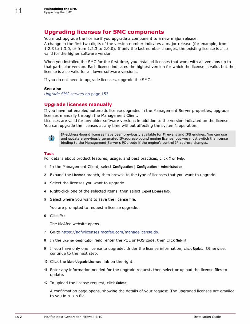
Upgrading licenses for SMC componentsYou must upgrade the license if you upgrade a component to a new major release.A change in the first two digits of the version number indicates a major release (for example, from1.2.3 to 1.3.0, or from 1.2.3 to 2.0.0). If only the last number changes, the existing license is alsovalid for the higher software version.
When you installed the SMC for the first time, you installed licenses that work with all versions up tothat particular version. Each license indicates the highest version for which the license is valid, but thelicense is also valid for all lower software versions.
If you do not need to upgrade licenses, upgrade the SMC.
See also Upgrade SMC servers on page 153
Upgrade licenses manuallyIf you have not enabled automatic license upgrades in the Management Server properties, upgradelicenses manually through the Management Client.Licenses are valid for any older software versions in addition to the version indicated on the license.You can upgrade the licenses at any time without affecting the system’s operation.
IP-address-bound licenses have been previously available for Firewalls and IPS engines. You can useand update a previously generated IP-address-bound engine license, but you must switch the licensebinding to the Management Server’s POL code if the engine’s control IP address changes.
TaskFor details about product features, usage, and best practices, click ? or Help.
1 In the Management Client, select Configuration | Configuration | Administration.
2 Expand the Licenses branch, then browse to the type of licenses that you want to upgrade.
3 Select the licenses you want to upgrade.
4 Right-click one of the selected items, then select Export License Info.
5 Select where you want to save the license file.
You are prompted to request a license upgrade.
6 Click Yes.
The McAfee website opens.
7 Go to https://ngfwlicenses.mcafee.com/managelicense.do.
8 In the License Identification field, enter the POL or POS code, then click Submit.
9 If you have only one license to upgrade: Under the license information, click Update. Otherwise,continue to the next step.
10 Click the Multi-Upgrade Licenses link on the right.
11 Enter any information needed for the upgrade request, then select or upload the license files toupdate.
12 To upload the license request, click Submit.
A confirmation page opens, showing the details of your request. The upgraded licenses are emailedto you in a .zip file.
11 Maintaining the SMCUpgrading the SMC
152 McAfee Next Generation Firewall 5.10 Installation Guide

Install licensesAfter you have upgraded the licenses, install the license in the Management Client.
TaskFor details about product features, usage, and best practices, click ? or Help.
1 In the Management Client, select File | System Tools | Install Licenses.
The Install License Files dialog box opens.
2 Select the license files and click Install.
3 Browse to Licenses | All Licenses | Administration Configuration in the view.
4 Check that the licenses have now been correctly upgraded to the new version.
When you only upgrade the software version in the license, old licenses are automatically replaced.
Upgrade SMC serversYou can upgrade SMC servers without uninstalling the previous version. A change in the Managementplatform, such as a new operating system or different hardware, requires reinstalling the SMC.
All SMC components (Management Server, Management Client, Log Server, and the optional Web PortalServer) must use the same SMC software version to work together. If you have multiple ManagementServers or Log Servers, you must upgrade each server separately.
The same installer works with all SMC components, including locally installed Management Clients.
If you have multiple Management Servers or Log Servers, you can upgrade them in any order.Management Servers are automatically isolated from database replication during the upgrade. There isno need to explicitly isolate the Management Servers before upgrading.
If you are upgrading from a very old version of the SMC, you might have to upgrade to anintermediate version first before upgrading to the latest version. See the Release Notes.
TaskFor details about product features, usage, and best practices, click ? or Help.
1 Start the installation in one of the following ways:
• From a .zip file — Unzip the file, then run setup.exe on Windows or setup.sh on Linux.
• From a DVD — Insert the installation DVD, then run the setup executable from the DVD.
Operating system Path to executable
Windows 64-bit \McAfee_SMC_Installer\Windows-x64\setup.exe
Linux 32-bit /McAfee_SMC_Installer/Linux/setup.sh
Linux 64-bit /McAfee_SMC_Installer/Linux-x64/setup.sh
If the DVD is not automatically mounted in Linux, mount the DVD with “mount /dev/cdrom /mnt/cdrom”.
2 To continue with the installation, read and accept the License Agreement.
The Installation Wizard automatically detects the previous installation directory.
Maintaining the SMCUpgrading the SMC 11
McAfee Next Generation Firewall 5.10 Installation Guide 153

3 To accept the installation directory, click Next.
The Installation Wizard displays the components to be upgraded.
4 (Management Server only, optional) To save a copy of the current installation that you can revert toat any time after the upgrade, select Save Current Installation.
5 Click Next.
6 (Management Server only) Select whether to back up the server, then click Next:• To create a backup that can be used and viewed without a password, select Yes.
• To create a password-protected backup, select Yes, encrypt the backup. You are prompted for thepassword as you confirm the selection.
• If you already have a recent backup of the Management Server, select No.
7 Check the preinstallation summary, then click Install.
The upgrade begins.
8 (Optional) When the upgrade is complete, click the links in the notification to view the reports ofchanges the installer has made.
The report opens in your web browser.
9 To close the installer, click Done.
10 Upgrade any SMC components that run on other computers (for example, additional ManagementServers or Log Servers) in the same way.
11 (Multiple Management Servers only) Synchronize the management database between theManagement Servers.
Synchronize databases between active Management Server andadditional Management ServersYou must synchronize the configuration information manually through the Management Client afterupgrading the Management Servers or after restoring a backup.
Before you beginThere must be a route between the Management Client and the Management Servers. Ifthere is no route between the Management Client and the Management Servers, youcannot send a command through the Control Management Servers dialog box.
Manual management database synchronization is primarily meant for resynchronizing the databasesafter upgrading the SMC. We do not recommend using manual database synchronization unless youhave a specific need to do so.
TaskFor details about product features, usage, and best practices, click ? or Help.
1 Connect to the active Management Server using the Management Client.
2 Select File | System Tools | Control Management Servers.
The Control Management Servers dialog box opens.
11 Maintaining the SMCUpgrading the SMC
154 McAfee Next Generation Firewall 5.10 Installation Guide

3 If the Management Client is in a different network than the additional Management Server, selectthe Location from which to send the command.
This action ensures that the command is sent to the correct Contact Address for the ManagementServer.
4 For each additional Management Server that you want to synchronize:
a Right-click the Management Server and select Replication | Full Database Replication.
You are prompted to confirm the replication.
b Click Yes.
All existing configurations on the additional Management Server are overwritten.
c Click OK to acknowledge the completion of the synchronization and wait for the ManagementServer to restart.
After the Management Server has restarted, its Replication Status is updated in the ControlManagement Servers dialog box.
5 Click Close to close the Control Management Servers dialog box.
Uninstall the SMCUsually, it is not necessary to uninstall the SMC. You can uninstall the SMC if you have a specific needto do so.
If you have several SMC components installed on the same computer, you cannot uninstall the SMCcomponents one by one.
By default, the SMC is installed in the following directories:
• Windows — C:\McAfee\Security Management Center
• Linux — /usr/local/mcafee/security_management_center
There is a .stonegate directory in each user’s home directory in the operating system, which containsthe Management Client configuration files. These files are not automatically deleted. You can deletethem manually after the uninstallation.
The sgadmin account is deleted during the uninstallation of the SMC.
Back up the Management Server and the Log Server to an external system before uninstalling the SMCif you want to preserve the stored data.
Tasks• Uninstall the SMC in Windows on page 156
Use this process to uninstall the SMC in a Windows environment.
• Uninstall the SMC in Linux on page 156Use this process to uninstall the SMC in a Linux environment.
Maintaining the SMCUninstall the SMC 11
McAfee Next Generation Firewall 5.10 Installation Guide 155

Uninstall the SMC in WindowsUse this process to uninstall the SMC in a Windows environment.
Task1 Start the uninstaller in one of the following ways:
• Open the list of installed programs through the Windows Control Panel, right-click McAfee SecurityManagement Center, and select Uninstall/Change.
• Alternatively, run the script <installation directory>\uninstall\ uninstall.bat.
2 When the uninstaller opens, click Uninstall.
All Security Management Center components are uninstalled.
Uninstall the SMC in LinuxUse this process to uninstall the SMC in a Linux environment.
You can uninstall the SMC in graphical mode or in non-graphical mode.
Task1 Stop the Security Management Center components on the computer.
2 Run the uninstaller script.
• To uninstall in graphical mode, run the script <installation directory>/uninstall/uninstall.sh.
• To uninstall in non-graphical mode, run the script the script <installation directory>/uninstall/uninstall.sh -nodisplay.
3 (Graphical mode only) When the uninstaller starts, click Uninstall.
All SMC components are uninstalled.
11 Maintaining the SMCUninstall the SMC
156 McAfee Next Generation Firewall 5.10 Installation Guide

12 Upgrading McAfee NGFW engines
When there is a new version of the McAfee NGFW software, upgrade the McAfee NGFW engines assoon as possible.
Contents How engine upgrades work Obtain McAfee NGFW engine upgrade files Upgrading or generating licenses for McAfee NGFW engines Upgrade engines remotely Upgrade engines locally
How engine upgrades workYou can remotely upgrade engines using the Management Client or locally on the engine commandline.
The upgrade package is imported to the Management Server manually or automatically. Before theimport, the Management Server verifies the digital signature of the upgrade package using a validTrusted Update Certificate. The signature must be valid for the import to succeed. Verification mightfail for the following reasons:
• The SMC version is out of date. Upgrade the SMC before upgrading the engines.
• A signature is invalid or missing in the upgrade files. Obtain an official upgrade package.
After the upgrade package has been imported, you can apply it to selected engines through theManagement Client. Before the upgrade is installed on the engines, the Management Server againverifies the digital signature of the upgrade package.
The engines have two alternative partitions for the software. When you install a new software version,it is installed on the inactive partition and the current version is preserved. This configuration allowsrollback to the previous version in case there are problems with the upgrade. If the engine is not ableto return to operation after the upgrade, it automatically switches back to the previous softwareversion at the next restart. You can also switch the active partition manually.
You can upload and activate the new software separately. For example, you can upload the upgradeduring office hours but activate it during a service window.
The currently installed working configuration (routing, policies) is stored separately and is not changedin an upgrade or a rollback. Although parts of the configuration can be version-specific (for example, ifsystem communications ports are changed), the new software version can use the existingconfiguration. Possible version-specific adjustments are made when you refresh the policy after theupgrade.
12
McAfee Next Generation Firewall 5.10 Installation Guide 157

Limitations
It is not possible to upgrade between a 32-bit version and a 64-bit version of the software. If you arerunning the software on third-party hardware, you can reinstall the software using the other version.In clusters, 32-bit and 64-bit nodes cannot be online simultaneously. Appliances support only thesoftware architecture version that they are preinstalled with.
You cannot upgrade Virtual Security Engines directly. To upgrade Virtual Security Engines, you mustupgrade the Master Engine that hosts the Virtual Security Engines.
What do I need to know before I begin?
The SMC must be up to date before you upgrade the engines. An old SMC version might not be able torecognize the new version engines and can generate an invalid configuration for them. TheManagement Server can control several older versions of engines. See the Release Notes forversion-specific compatibility information.
During a cluster upgrade, it is possible to have the upgraded nodes online and operational side by sidewith the older version nodes. This way, you can upgrade the nodes one by one while the other nodeshandle the traffic. However, you must upgrade all nodes to the same version as soon as possible, asprolonged use with mismatched versions is not supported.
The current engine version is displayed on the General tab in the Info pane when you select the engine.If the Info pane is not shown, select View | Info.
Beginning from version 5.9, all McAfee Next Generation Firewall licenses include the anti-malwarefeature by default.
Configuration overview
Follow these general steps to upgrade engines:
1 (Manual download of engine upgrade files) Prepare the installation files.
2 (Manual license updates) Update the licenses.
3 Upgrade the engines.
Obtain McAfee NGFW engine upgrade filesIf the Management Server is not set up to download engine upgrades automatically or if you want toupgrade engines locally, download the installation files manually.
Check the installation file integrity using the MD5 or SHA-1 file checksums. Windows does not haveMD5 or SHA-1 checksum programs by default, but there are several third-party programs available.
Task1 Go to https://ngfwlicenses.mcafee.com/managelicense.do.
2 Select Patches and Downloads.
The Full Product Downloads and Updates page opens.
3 Select Next Generation Firewall Downloads.
The McAfee License Center page opens.
4 Log on to the License Center.
12 Upgrading McAfee NGFW enginesObtain McAfee NGFW engine upgrade files
158 McAfee Next Generation Firewall 5.10 Installation Guide

5 In the License Identification field, enter the Proof-of-License (POL) or Proof-of-Serial (POS) code andclick Submit.
6 Click Security Engine Downloads.
The Security Engine Downloads page opens.
7 Download the installation file.
There are two types of packages available:
• The .zip file is used in the remote upgrade on all supported platforms. It can also be used for alocal upgrade from a USB drive or a non-bootable DVD.
• The .iso download allows you to create a bootable installation DVD for a local upgrade onplatforms that have an optical drive.
8 Change to the directory that contains the files to be checked.
9 (Linux only) Generate a checksum of the file using the command md5sum filename or sha1sumfilename, where file name is the name of the installation file.
For Windows, see the documentation for the third-party checksum program.
Example:
$ md5sum sg_engine_1.0.0.1000.iso869aecd7dc39321aa2e0cfaf7fafdb8f sg_engine_1.0.0.1000.iso
10 Compare the displayed output to the checksum on the website.
Do not use files that have invalid checksums. If downloading the files again does not help, contactMcAfee support to resolve the issue.
Prepare a downloaded .zip file for a remote upgrade.
1 Log on to the Management Client and select File | Import | Import Engine Upgrades.
2 Select the engine upgrade (sg_engine_version_platform.zip) file and click Import.
The status bar at the bottom of the Management Client window shows the progress of the import.
The Management Server verifies the digital signature of the .zip file before importing it. Thesignature must be valid for the import to succeed. If the verification fails, an error message isshown. Verification failure can result from an out-of-date SMC version or an invalid or missingsignature.
Prepare a downloaded .zip file for a local upgrade.
Copy the file to the root directory of a USB drive or a DVD.
Prepare a downloaded .iso file for a local upgrade.
Create the installation DVD for the engines with a DVD-burning application that can correctly readand burn the DVD-structure stored in the .iso images. If the end result is a DVD file with theoriginal .iso file on it, the DVD cannot be used for installation.
If you are sure that you do not need to upgrade your licenses, upgrade the SMC, firewalls, IPSengines, Layer 2 Firewalls, or Master Engines. Continue in one of the following ways:
• Upgrade the engines remotely through the Management Server.
• Upgrade the engine locally at the engine site.
Otherwise, upgrade or generate licenses.
Upgrading McAfee NGFW enginesObtain McAfee NGFW engine upgrade files 12
McAfee Next Generation Firewall 5.10 Installation Guide 159

See also Upgrade engines remotely on page 162Upgrade engines locally on page 163
Upgrading or generating licenses for McAfee NGFW enginesIn some cases, you must upgrade licenses when you are upgrading an engine.
When you installed the engine software for the first time, you installed licenses that work with allversions of the engine up to that particular version. If the first two numbers in the old and the newversions are the same, the upgrade can be done without upgrading licenses (for example, whenupgrading from 1.2.3 to 1.2.4). When either of the first two numbers in the old version and the newversion are different, you must first upgrade your licenses (for example, when upgrading from 1.2.3 to1.3.0). By default, licenses are regenerated and installed automatically.
You can view and download your current licenses online at https://ngfwlicenses.mcafee.com/managelicense.do. You can also upgrade the licenses.
If you do not need to upgrade licenses, upgrade the engines.
If you need new licenses and you want to upgrade the licenses one at a time, upgrade licenses underone proof code.
If you need new licenses and you want to upgrade several licenses at the same time, upgrade licenseswith multiple proof codes.
See also Upgrade engines remotely on page 162Upgrade engines locally on page 163
Upgrade licenses under one proof codeA license generated under one proof-of-license (POL) or proof-of-serial (POS) code can contain thelicense information for several components.
You can also use the multi-upgrade form to upgrade the licenses.
Task1 Go to https://ngfwlicenses.mcafee.com/managelicense.do.
2 Enter the POL or POS code in the License Identification field and click Submit.
The License Center page opens.
3 Click Update.
The License View page opens.
4 Follow the directions to upgrade the license.
Upgrade licenses with multiple proof codesIf you have several existing licenses with different proof-of-license (POL) or proof-of-serial (POS)codes to upgrade, generate all new licenses at the same time.
12 Upgrading McAfee NGFW enginesUpgrading or generating licenses for McAfee NGFW engines
160 McAfee Next Generation Firewall 5.10 Installation Guide
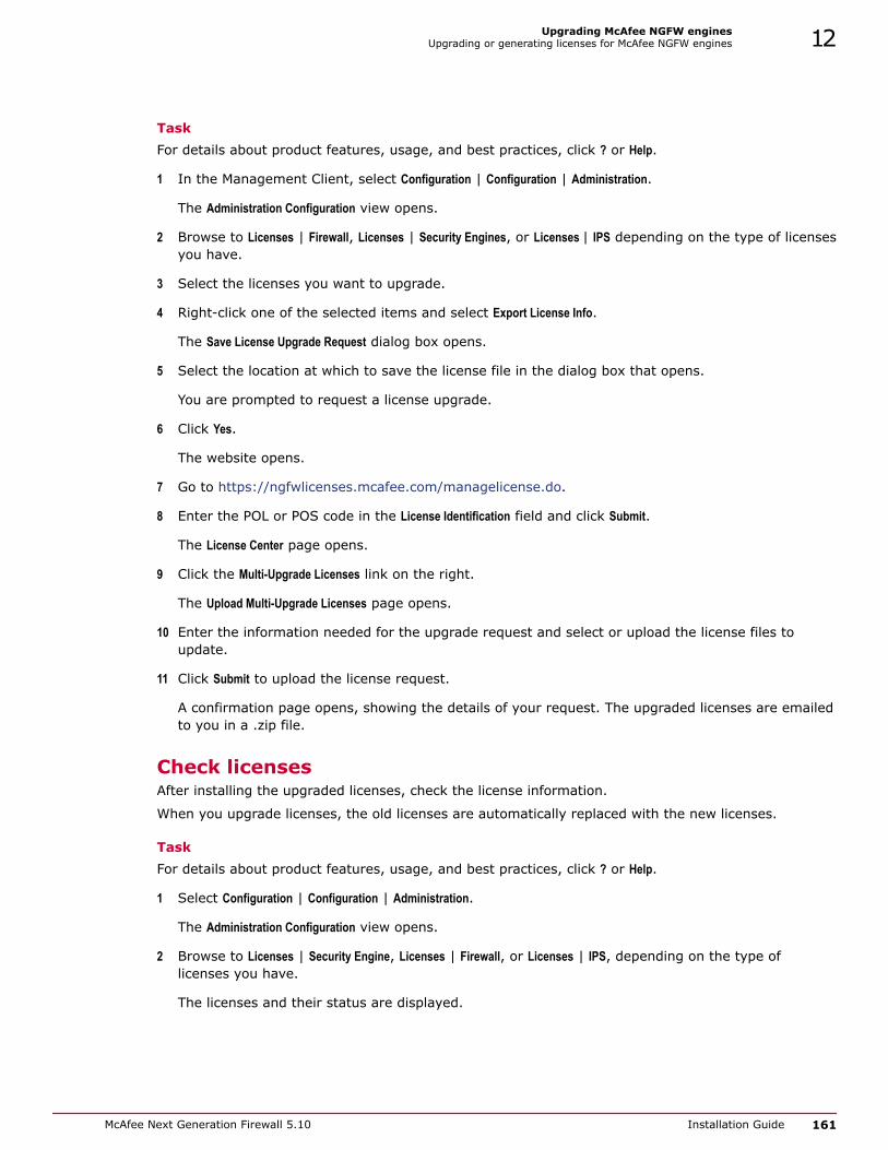
TaskFor details about product features, usage, and best practices, click ? or Help.
1 In the Management Client, select Configuration | Configuration | Administration.
The Administration Configuration view opens.
2 Browse to Licenses | Firewall, Licenses | Security Engines, or Licenses | IPS depending on the type of licensesyou have.
3 Select the licenses you want to upgrade.
4 Right-click one of the selected items and select Export License Info.
The Save License Upgrade Request dialog box opens.
5 Select the location at which to save the license file in the dialog box that opens.
You are prompted to request a license upgrade.
6 Click Yes.
The website opens.
7 Go to https://ngfwlicenses.mcafee.com/managelicense.do.
8 Enter the POL or POS code in the License Identification field and click Submit.
The License Center page opens.
9 Click the Multi-Upgrade Licenses link on the right.
The Upload Multi-Upgrade Licenses page opens.
10 Enter the information needed for the upgrade request and select or upload the license files toupdate.
11 Click Submit to upload the license request.
A confirmation page opens, showing the details of your request. The upgraded licenses are emailedto you in a .zip file.
Check licensesAfter installing the upgraded licenses, check the license information.
When you upgrade licenses, the old licenses are automatically replaced with the new licenses.
TaskFor details about product features, usage, and best practices, click ? or Help.
1 Select Configuration | Configuration | Administration.
The Administration Configuration view opens.
2 Browse to Licenses | Security Engine, Licenses | Firewall, or Licenses | IPS, depending on the type oflicenses you have.
The licenses and their status are displayed.
Upgrading McAfee NGFW enginesUpgrading or generating licenses for McAfee NGFW engines 12
McAfee Next Generation Firewall 5.10 Installation Guide 161

3 Verify that all engines are correctly licensed.
4 If any engines are not correctly licensed, you might need to upgrade or generate the licensesagain.
Continue the upgrade in one of the following ways:
• Upgrade the engines remotely through the Management Server.
• Upgrade the engines on the engine command line.
Upgrade engines remotelyThe Management Server can remotely upgrade engine components that it manages.
Before you beginBefore upgrading remotely, read the Release Notes for the new version, especially therequired SMC version and any other version-specific upgrade issues that might be listed.You can locate the release notes as follows. Select Configuration | Configuration | Administration,then select Other Elements | Engine Upgrades. Select the type of engine you are upgrading. A linkto the release notes is included in the upgrade file’s information. If the Management Serverhas no Internet connectivity, you can find the release notes at http://support.mcafee.com
You can upgrade several engines of the same type in the same operation. However, we recommendthat you upgrade clusters one node at a time and wait until an upgraded node is back online beforeyou upgrade the other nodes. Clusters operate normally throughout the upgrade when the upgrade isdone in stages. However, it is recommended to upgrade all nodes in the cluster to the same version assoon as possible. Prolonged use with mismatched versions is not supported. It is not possible to have32-bit and 64-bit engines online in the cluster at the same time.
You cannot remotely upgrade McAfee NGFW engines in the AWS cloud using the Management Client.You must upgrade these engines using the AWS cloud management infrastructure. For upgradeinstructions, see KB85950.
TaskFor details about product features, usage, and best practices, click ? or Help.
1 Select Monitoring | System Status.
The System Status view opens.
2 Right-click the node you want to upgrade, then select Commands | Go Offline.
A confirmation dialog box opens.
3 (Optional) Enter an Audit Comment to be shown in the audit log entry that is generated when yousend the command to the engine.
4 Click Yes.
The engine is turned offline shortly.
12 Upgrading McAfee NGFW enginesUpgrade engines remotely
162 McAfee Next Generation Firewall 5.10 Installation Guide

5 Right-click the node you want to upgrade, then select Upgrade Software or Configuration | Upgrade Softwaredepending on your selection.
You cannot upgrade Virtual Security Engines directly. To upgrade Virtual Security Engines, you mustupgrade the Master Engine that hosts the Virtual Security Engines.
The Remote Upgrade Task Properties dialog box opens.
6 Select the type of Operation you want to perform:
• Select Remote Upgrade (transfer + activate) to install the new software and reboot the node with thenew version of the software.
• Select Remote Upgrade (transfer) to install the new software on the node without an immediatereboot and activation. The node continues to operate with the currently installed version untilyou choose to activate the new version.
• Select Remote Upgrade (activate) to reboot the node and activate the new version of the software thatwas installed earlier.
To avoid an outage, do not activate the new configuration simultaneously on all nodes of a cluster.Activate the new configuration one node at a time, and proceed to the next node only after theprevious node is back online.
7 If necessary, add or remove Target engines.
All engines in the same Upgrade Task must be of the same type.
8 Select the correct Engine Upgrade file, then click OK.
If you choose to activate the new configuration, you are prompted to acknowledge a warning thatthe node will be rebooted. A new tab opens showing the progress of the upgrade. The time theupgrade takes varies depending on the performance of your system and the network environment.The engine is automatically rebooted and brought back online.
The upgrade overwrites the inactive partition and then switches the active partition. To undo theupgrade, use the sg-toggle-active command or the engine’s boot menu to switch back to theprevious software version on the other partition. This switch can also happen automatically at thenext reboot if the engine is not able to successfully return to operation when it boots up after theupgrade.
The Management Server verifies the digital signature of the upgrade package before installing it.The signature must be valid for the upgrade to succeed. If the verification fails, an error message isshown. Verification failure can result from an out-of-date SMC version or an invalid or missingsignature.
Upgrade engines locallyYou can upgrade the engines on the engine command line.
Before you beginUpgrading locally requires a physical connection to the engine using a monitor andkeyboard or a serial cable.
During a Firewall Cluster or Master Engine cluster upgrade, the upgraded nodes can be online andoperational side by side with the older version nodes. However, you must upgrade all nodes to thesame version as soon as possible, as prolonged use with mismatched versions is not supported.
Upgrading McAfee NGFW enginesUpgrade engines locally 12
McAfee Next Generation Firewall 5.10 Installation Guide 163

There are two ways to upgrade engines locally:
• If the hardware has a DVD drive (a USB DVD drive can be used) and you have an installation DVD,you can upgrade from an installation DVD.
• You can upgrade from a .zip file on a USB drive or on a DVD.
Upgrade from an installation DVDYou can upgrade the engines to the latest version from a DVD that was shipped to you, or from a DVDthat you have created from an .iso image that you downloaded from the McAfee website.
Task1 Log on to the node as root with the password you set for the engine (you can set the password
through the Management Client).
2 Insert the DVD into the engine’s DVD drive.
3 Restart the node from the DVD with the command reboot (recommended) or by cycling the power(if you cannot log on).
You are promoted to select the upgrade type.
4 Enter 1 to upgrade the existing installation and press Enter to continue.
The upgrade process starts.
5 When the process is finished, eject the DVD and press Enter to restart.
If the McAfee NGFW Configuration Wizard opens, configure the engine in the same way as after the firstinstallation.
6 When the upgrade is finished, right-click the node in the Management Client and select Commands |Go Online.
A confirmation dialog box opens.
7 (Optional) Enter an Audit Comment to be shown in the audit log entry that is generated when yousend the command to the engine.
8 Click Yes.
If you are upgrading a cluster, start the upgrade on the next node only when the upgraded node isback online.
See also Configure McAfee NGFW engine software with the McAfee NGFW Configuration Wizard on page132
Upgrade from a .zip fileYou can use a .zip file to upgrade the engine software locally on the engine command line.
Task1 Log on to the node as root with the password set for the engine (you can set the password through
the Management Client).
2 Insert the USB drive or the DVD.
12 Upgrading McAfee NGFW enginesUpgrade engines locally
164 McAfee Next Generation Firewall 5.10 Installation Guide

3 Run the command sg-reconfigure.
The McAfee NGFW Configuration Wizard opens.
4 Select Upgrade and press Enter.
5 Select the source media where the upgrade file is located.
6 Select OK.
The software is upgraded.
The McAfee NGFW engine verifies the digital signature of the upgrade package before installing it.The verification can take several minutes. The signature must be valid for the upgrade to succeed. Ifthe verification fails, an error message is shown. Verification failure can result from an out-of-dateMcAfee NGFW software version or an invalid or missing signature.
7 When prompted, press Enter.
The engine restarts with the new version.
Upgrading McAfee NGFW enginesUpgrade engines locally 12
McAfee Next Generation Firewall 5.10 Installation Guide 165

12 Upgrading McAfee NGFW enginesUpgrade engines locally
166 McAfee Next Generation Firewall 5.10 Installation Guide

A Default communication ports
There are default ports used in connections between SMC components and default ports that SMCcomponents use with external components.
Contents Security Management Center ports McAfee NGFW engine ports
McAfee Next Generation Firewall 5.10 Installation Guide 167

Security Management Center portsThe most important default ports used in communications to and from SMC components are presentedin the following illustrations.
Figure A-1 Destination ports for basic communications within the SMC
Figure A-2 Default destination ports for optional SMC components and features
This table lists the default ports SMC uses internally and with external components. Many of theseports can be changed. The names of corresponding default Service elements are also included for yourreference.
A Default communication portsSecurity Management Center ports
168 McAfee Next Generation Firewall 5.10 Installation Guide

Table A-1 SMC default ports
Listeninghost
Port/protocol
Contactinghosts
Service description Service elementname
AdditionalManagementServers
8902-8913/TCP
ManagementServer
Database replication (push) tothe additional ManagementServer.
SG Control
DNS server 53/UDP,53/TCP
ManagementClient,ManagementServer, LogServer
DNS queries. DNS (UDP)
LDAP server 389/TCP ManagementServer
External LDAP queries fordisplay/editing in theManagement Client.
LDAP (TCP)
Log Server 162/UDP,5162/UDP
Monitoredthird-partycomponents
SNMPv1 trap reception fromthird-party components.
Port 162 is used if installed onWindows, port 5162 if installedon Linux.
SNMP (UDP)
Log Server 514/TCP,514/UDP,5514/TCP,5514/UDP
Monitoredthird-partycomponents
Syslog reception from third-partycomponents.
Port 514 is used if installed onWindows, port 5514 if installedon Linux.
Syslog (UDP)
[Partial match]
Log Server 2055/UDP Monitoredthird-partycomponents
NetFlow or IPFIX reception fromthird-party components. Port2055 is used in both Windowsand Linux.
NetFlow (UDP)
Log Server 3020/TCP Log Server,Web PortalServer,SecurityEngines
Alert sending from the Log Serverand Web Portal Server.
Log and alert messages;monitoring of blacklists,connections, status, and statisticsfrom Security Engines.
SG Log
Log Server 8914-8918/TCP
ManagementClient
Log browsing. SG Data Browsing
Log Server 8916-8917/TCP
Web PortalServer
Log browsing. SG Data Browsing(Web PortalServer)
ManagementServer
3021/TCP Log Server,Web PortalServer
System communicationscertificate request/renewal.
SG Log InitialContact
ManagementServer
8902-8913/TCP
ManagementClient, LogServer, WebPortal Server
Monitoring and controlconnections.
SG Control
ManagementServer
3023/TCP AdditionalManagementServers, LogServer, WebPortal Server
Log Server and Web Portal Serverstatus monitoring.
Status information from anadditional Management Server tothe active Management Server.
SG StatusMonitoring
Default communication portsSecurity Management Center ports A
McAfee Next Generation Firewall 5.10 Installation Guide 169

Table A-1 SMC default ports (continued)
Listeninghost
Port/protocol
Contactinghosts
Service description Service elementname
ManagementServer
8903,8907/TCP
AdditionalManagementServers
Database replication (pull) to theadditional Management Server.
SG Control
Monitoredthird-partycomponents
161/UDP Log Server SNMP status probing to externalIP addresses.
SNMP (UDP)
NTP server 123/TCP orUDP
SMC Appliance Receiving NTP information. NTP
RADIUS server 1812/UDP ManagementServer
RADIUS authentication requestsfor administrator logon.
The default ports can be edited inthe properties of the RADIUSServer element.
RADIUS(Authentication)
McAfeeMcAfee NGFWupdate service
443/TCP SMC servers Update packages, engineupgrades, and licenses.
HTTPS
SMC Appliance 161/UDP Third-partycomponents
Requesting health and otherinformation about the SMCAppliance.
SNMP
Updateservers
443/TCP SMC Appliance Receiving appliance patches andupdates.
HTTPS
SMC Appliance 22/TCP Terminalclients
SSH connections to the commandline of the SMC Appliance(disabled in FIPS mode).
SSH
Syslog server 514/UDP,5514/UDP
Log Server Log data forwarding to syslogservers.
The default ports can be edited inthe LogServerConfiguration.txtfile.
Syslog (UDP)
[Partial match]
Terminal Client
Firewall, Layer2 Firewall,IPS, MasterEngine
22/TCP SMC Appliance Contacting engines and movingSMC Appliance backups off theappliance.
SSH is disabled in FIPSmode.
SSH
Third-partycomponents
2055/UDP Log Server NetFlow or IPFIX forwarding tothird-party components.
Port 2055 is used in bothWindows and Linux.
NetFlow (UDP)
Third-partycomponents
162/UDP SMC Appliance Sending SNMP status probing toexternal devices.
SNMP
Third-partycomponents
445/TCP SMC Appliance Moving SMC Appliance backupsoff the appliance.
CIFS is disabled in FIPSmode.
CIFS
A Default communication portsSecurity Management Center ports
170 McAfee Next Generation Firewall 5.10 Installation Guide

McAfee NGFW engine portsThe most important default ports used in communications to and from Security Engines and MasterEngines are presented in the following illustrations.
See the table for a complete list of default ports for the engines.
Master Engines use the same default ports as clustered Security Engines. Virtual Security Engines donot communicate directly with other system components.
Figure A-3 Destination ports for basic Security Engine communications
Figure A-4 Default destination ports for Security Engine service communications
This table lists the default ports for Security Engines and Master Engines. Many of these ports can bechanged. The names of corresponding default Service elements are also included for your reference.
Default communication portsMcAfee NGFW engine ports A
McAfee Next Generation Firewall 5.10 Installation Guide 171
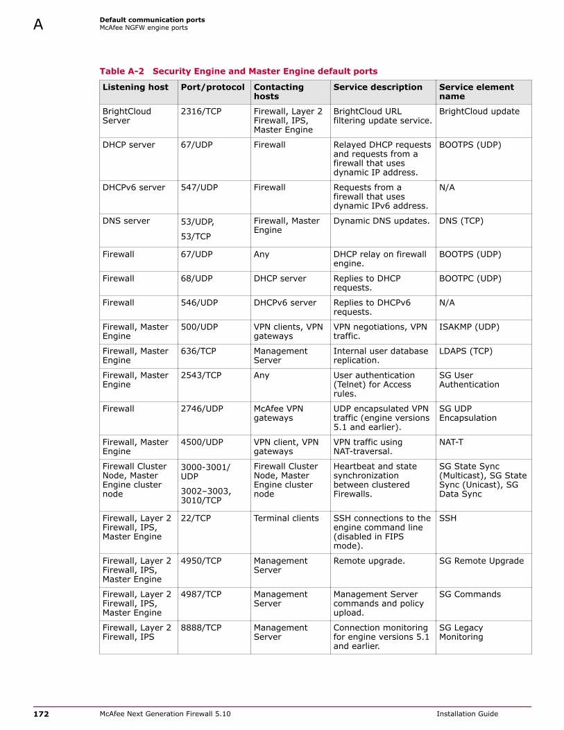
Table A-2 Security Engine and Master Engine default ports
Listening host Port/protocol Contactinghosts
Service description Service elementname
BrightCloudServer
2316/TCP Firewall, Layer 2Firewall, IPS,Master Engine
BrightCloud URLfiltering update service.
BrightCloud update
DHCP server 67/UDP Firewall Relayed DHCP requestsand requests from afirewall that usesdynamic IP address.
BOOTPS (UDP)
DHCPv6 server 547/UDP Firewall Requests from afirewall that usesdynamic IPv6 address.
N/A
DNS server 53/UDP,
53/TCP
Firewall, MasterEngine
Dynamic DNS updates. DNS (TCP)
Firewall 67/UDP Any DHCP relay on firewallengine.
BOOTPS (UDP)
Firewall 68/UDP DHCP server Replies to DHCPrequests.
BOOTPC (UDP)
Firewall 546/UDP DHCPv6 server Replies to DHCPv6requests.
N/A
Firewall, MasterEngine
500/UDP VPN clients, VPNgateways
VPN negotiations, VPNtraffic.
ISAKMP (UDP)
Firewall, MasterEngine
636/TCP ManagementServer
Internal user databasereplication.
LDAPS (TCP)
Firewall, MasterEngine
2543/TCP Any User authentication(Telnet) for Accessrules.
SG UserAuthentication
Firewall 2746/UDP McAfee VPNgateways
UDP encapsulated VPNtraffic (engine versions5.1 and earlier).
SG UDPEncapsulation
Firewall, MasterEngine
4500/UDP VPN client, VPNgateways
VPN traffic usingNAT-traversal.
NAT-T
Firewall ClusterNode, MasterEngine clusternode
3000-3001/UDP
3002–3003,3010/TCP
Firewall ClusterNode, MasterEngine clusternode
Heartbeat and statesynchronizationbetween clusteredFirewalls.
SG State Sync(Multicast), SG StateSync (Unicast), SGData Sync
Firewall, Layer 2Firewall, IPS,Master Engine
22/TCP Terminal clients SSH connections to theengine command line(disabled in FIPSmode).
SSH
Firewall, Layer 2Firewall, IPS,Master Engine
4950/TCP ManagementServer
Remote upgrade. SG Remote Upgrade
Firewall, Layer 2Firewall, IPS,Master Engine
4987/TCP ManagementServer
Management Servercommands and policyupload.
SG Commands
Firewall, Layer 2Firewall, IPS
8888/TCP ManagementServer
Connection monitoringfor engine versions 5.1and earlier.
SG LegacyMonitoring
A Default communication portsMcAfee NGFW engine ports
172 McAfee Next Generation Firewall 5.10 Installation Guide

Table A-2 Security Engine and Master Engine default ports (continued)
Listening host Port/protocol Contactinghosts
Service description Service elementname
Firewall, Layer 2Firewall, IPS,Master Engine
15000/TCP ManagementServer, LogServer
Blacklist entries. SG Blacklisting
Firewall, Layer 2Firewall, IPS,Master Engine
161/UDP SNMP server SNMP monitoring. SNMP (UDP)
IPS Cluster Node 3000-3001/UDP
3002–3003,3010/TCP
IPS Cluster Node Heartbeat and statesynchronizationbetween clustered IPSengines.
SG State Sync(Multicast), SG StateSync (Unicast), SGData Sync
LDAP server 389/TCP Firewall, MasterEngine
External LDAP queries,including StartTLSconnections.
LDAP (TCP)
Layer 2 FirewallCluster Node
3000-3001/UDP 3002–3003,3010/TCP
Layer 2 FirewallCluster Node
Heartbeat and statesynchronizationbetween clusteredLayer 2 Firewalls.
SG State Sync(Multicast), SG StateSync (Unicast), SGData Sync
Log Server 3020/TCP Firewall, Layer 2Firewall, IPS,Master Engine
Log and alertmessages; monitoringof blacklists,connections, status,and statistics.
SG Log
Malwaresignature server
80/TCP Firewall, Layer 2Firewall, IPS,Master Engine
Malware signatureupdate service.
HTTP
ManagementServer
3021/TCP Firewall, Layer 2Firewall, IPS,Master Engine
Systemcommunicationscertificate request/renewal (initialcontact).
SG Initial Contact
ManagementServer
3023/TCP Firewall, Layer 2Firewall, IPS,Master Engine
Monitoring (status)connection.
SG Status Monitoring
ManagementServer
8906/TCP Firewall, Layer 2Firewall, IPS
Managementconnection for singleengines with"Node-Initiated Contactto Management Server"selected.
SG Dynamic Control
RADIUS server 1812,1645/UDP
Firewall, MasterEngine
RADIUS authenticationrequests.
RADIUS(Authentication),RADIUS (Old)
RPC server 111/UDP,
111/TCP
Firewall, MasterEngine
RPC number resolve. SUNRPC (UDP), SunRPC (TCP)
Server PoolMonitoringAgents
7777/UDP Firewall, MasterEngine
Polls to the servers'Server Pool MonitoringAgents for availabilityand load information.
SG Server PoolMonitoring
SNMP server 162/UDP Firewall, Layer 2Firewall, IPS,Master Engine
SNMP traps from theengine.
SNMP Trap (UDP)
Default communication portsMcAfee NGFW engine ports A
McAfee Next Generation Firewall 5.10 Installation Guide 173

Table A-2 Security Engine and Master Engine default ports (continued)
Listening host Port/protocol Contactinghosts
Service description Service elementname
TACACS+ server 49/TCP Firewall, MasterEngine
TACACS+authenticationrequests.
TACACS (TCP)
VPN gateways 500/UDP,
2746/UDP(McAfeegateways only),
or 4500 UDP.
Firewall, MasterEngine
VPN traffic. Ports 2746and 4500 can also beused, depending onencapsulation options.
ISAKMP (UDP)
A Default communication portsMcAfee NGFW engine ports
174 McAfee Next Generation Firewall 5.10 Installation Guide

B Command line tools
There are command line tools for the SMC and the McAfee NGFW engines.
Contents Security Management Center commands McAfee NGFW engine commands Server Pool Monitoring Agent commands
Security Management Center commandsSMC commands include commands for the Management Server, Log Server, and Web Portal Server.
Most of the commands are found in the <installation directory>/bin/ directory. In Windows, thecommand line tools are *.bat script files. In Linux, the files are *.sh scripts.
If you installed the Management Server in the C:\Program Files\McAfee\Security Management Centerdirectory in Windows, some of the program data is stored in the C:\ProgramData\McAfee\SecurityManagement Center directory. Command line tools can be found in the C:\Program Files\McAfee\Security Management Center\bin or the C:\ProgramData\McAfee\Security Management Center\bindirectory.
Commands that require parameters must be run through the command line (cmd.exe in Windows).Commands that do not require parameters can alternatively be run through a graphical user interface,and can be added as shortcuts during installation.
login and password parameters are optional. Giving them as command-line parameters can pose asecurity vulnerability. Do not enter logon and password information unless explicitly prompted to do soby a command line tool.
McAfee Next Generation Firewall 5.10 Installation Guide 175

Table B-1 Security Management Center commands
Command Description
ambr-crl(SMC Appliance only)
[-a ADD|--add=ADD][-d DELETE|--delete=DELETE][-q|--query][-iIMPORT_CRL|--import=IMPORT_CRL][-c|--clean][-v][-l <log file path>][-h|--help]
Fetches the certificate revocation lists (CRLs) for the CAcertificates used by the appliance maintenance and bugremediation (AMBR) utilities.
-a ADD, --add=ADD adds a CRL distribution point URL inthe form of http://<url>.
-d DELETE, --delete=DELETE deletes a CRL distributionpoint URL.
-q, --query lists CRL distribution points.
-i IMPORT_CRL, --import=IMPORT_CRL imports a CRLfrom a file.
-c, --clean removes existing CRLs before fetching newCRLs.
-v increases the verbosity of the command. You can repeatthis command up to two times (-vv or -v -v) to furtherincrease the verbosity.
-l <log file path> specifies the path to a log file.
-h, --help displays information about the command.
ambr-decrypt(SMC Appliance only)
Decrypts an ambr patch; not normally used byadministrators. ambr-install automatically decryptspatches.
ambr-install <patch>(SMC Appliance only)
[-F|--force][-r|--skip-revocation][--no-backup][--no-snapshot][-v][-l <log file path>][-h|--help]
Installs an ambr patch that has been loaded on thesystem.
You can install multiple patches with a space between eachpatch name.
-F, --force forces the reinstallation of the patch orpatches.
-r, --skip-revocation skips the certificate revocationchecks.
--no-backup does not create a configuration backup.
--no-snapshot does not create a recovery snapshot.
-v increases the verbosity of the command. You can repeatthis command up to two times to further increase theverbosity.
-l <log file path> specifies the path to a log file.
-h, --help displays information about the command.
B Command line toolsSecurity Management Center commands
176 McAfee Next Generation Firewall 5.10 Installation Guide
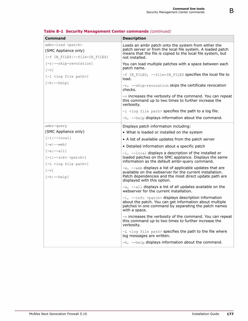
Table B-1 Security Management Center commands (continued)
Command Description
ambr-load <patch>(SMC Appliance only)
[-f IN_FILES|--file=IN_FILES][-r|--skip-revocation][-v][-l <log file path>][-h|--help]
Loads an ambr patch onto the system from either thepatch server or from the local file system. A loaded patchmeans that the file is copied to the local file system, butnot installed.
You can load multiple patches with a space between eachpatch name.
-f IN_FILES, --file=IN_FILES specifies the local file toload.
-r, --skip-revocation skips the certificate revocationchecks.
-v increases the verbosity of the command. You can repeatthis command up to two times to further increase theverbosity.
-l <log file path> specifies the path to a log file.
-h, --help displays information about the command.
ambr-query(SMC Appliance only)
[-l|--local][-w|--web][-a|--all][-i|--info <patch>][-L <log file path>][-v][-h|--help]
Displays patch information including:• What is loaded or installed on the system
• A list of available updates from the patch server
• Detailed information about a specific patch
-l, --local displays a description of the installed orloaded patches on the SMC appliance. Displays the sameinformation as the default ambr-query command.
-w, --web displays a list of applicable updates that areavailable on the webserver for the current installation.Patch dependencies and the most direct update path aredisplayed with this option.
-a, --all displays a list of all updates available on thewebserver for the current installation.
-i, --info <patch> displays description informationabout the patch. You can get information about multiplepatches in one command by separating the patch nameswith a space.
-v increases the verbosity of the command. You can repeatthis command up to two times to further increase theverbosity.
-L <log file path> specifies the path to the file wherelog messages are written.
-h, --help displays information about the command.
Command line toolsSecurity Management Center commands B
McAfee Next Generation Firewall 5.10 Installation Guide 177

Table B-1 Security Management Center commands (continued)
Command Description
ambr-unload <patch>(SMC Appliance only)
[-a|--all][-v][-l <log file path>][-h|--help]
Unloads an ambr patch from the system. The commanddeletes the patch file if it has not been installed, but it doesnot uninstall the patch.
You can unload multiple patches with a space betweeneach patch name.
-a, --all unloads all loaded patches.
-v increases the verbosity of the command. You can repeatthis command up to two times to further increase theverbosity.
-l <log file path> specifies the path to a log file.
-h, --help displays information about the command.
ambr-verify(SMC Appliance only)
Verifies the signature of a patch file; not normally used byadministrators. ambr-install automatically verifiespatches.
B Command line toolsSecurity Management Center commands
178 McAfee Next Generation Firewall 5.10 Installation Guide

Table B-1 Security Management Center commands (continued)
Command Description
sgArchiveExport[host=<Management ServerAddress[\Domain>][login=<login name>][pass=<password>][format=<exporter format: CSV orXML>]i=<input files and/or directories>[o=<output file name>][f=<filter file name>][e=<filter expression>][-h|-help|-?][-v]
Displays or exports logs from archive.
This command is only available on the Log Server. Theoperation checks permissions for the suppliedadministrator account from the Management Server toprevent unauthorized access to the logs.
Enclose details in double quotes if they contain spaces.
Host specifies the address of the Management Server. Ifthe parameter is not defined, the loopback address(localhost) is used.login defines the user name for the account that is usedfor this operation. If this parameter is not defined, the username root is used.
pass defines the password for the user account.
format defines the file format for the output file. If thisparameter is not defined, the XML format is used.
i defines the source from which the logs are exported. Canbe a folder or a file. The processing recurses intosubfolders.
o defines the destination file where the logs are exported.If this parameter is not defined, the output is displayed onscreen.
f defines a file that contains the filtering criteria you wantto use for filtering the log data. You can export log filtersindividually in the Management Client through Tools | Savefor Command Line Tools in the filter's right-click menu.
e allows you to enter a filter expression manually (usingthe same syntax as exported filter files).
-h, -help, or -? displays information about using thescript.
-v displays verbose output on the command execution.
Example (exports logs from one full day to a file using afilter): sgArchiveExport login=admin pass=abc123i=c:/mcafee/security_management_center/data/archive/firewall/year2011/month12/./sgB.day01/f=c:/mcafee/security_management_center/export/MyExportedFilter.flp format=CSVo=MyExportedLogs.csv
Command line toolsSecurity Management Center commands B
McAfee Next Generation Firewall 5.10 Installation Guide 179

Table B-1 Security Management Center commands (continued)
Command Description
sgBackupLogSrv[pwd=<password>][path=<destpath>]destpath[nodiskcheck][comment=<comment>][nofsstorage][-h|--help]
Creates a backup of Log Server configuration data.
The backup file is stored in the <installation directory>/backups/ directory.
Twice the size of the log database is required on thedestination drive. Otherwise, the operation fails.
pwd enables encryption.
path defines the destination path.
nodiskcheck ignores the free disk check before creatingthe backup.
comment allows you to enter a comment for the backup.The maximum length of a comment is 60 characters.
nofsstorage creates a backup only of the Log Serverconfiguration without the log data.
-h or --help displays information about using the script.
sgBackupMgtSrv[pwd=<password>][path=<destpath>][nodiskcheck][comment=<comment>][-h|--help]
Creates a complete backup of the Management Server(including both the local configuration and the storedinformation in the configuration database). The backup fileis stored in the <installation directory>/backups/ directory.
Twice the size of the Management Server database isrequired on the destination drive. Otherwise, the operationfails.
pwd enables encryption.
path defines the destination path.
nodiskcheck ignores the free disk check before creatingthe backup.
comment allows you to enter a comment for the backup.The maximum length of a comment is 60 characters.
-h or --help displays information about using the script.
Also see sgRestoreMgtBackup andsgRecoverMgtDatabase.
sgCertifyLogSrv[host=<Management ServerAddress[\Domain]>
Contacts the Management Server and creates a certificatefor the Log Server to allow secure communications withother SMC components. Renewing an existing certificatedoes not require changing the configuration of any otherSMC components.
host specifies the address of the Management Server. Ifthe parameter is not defined, the loopback address(localhost) is used.
Domain specifies the administrative Domain the Log Serverbelongs to if the system is divided into administrativeDomains. If the Domain is not specified, the SharedDomain is used.
Stop the Log Server before running this command. Restartthe server after running this command.
B Command line toolsSecurity Management Center commands
180 McAfee Next Generation Firewall 5.10 Installation Guide

Table B-1 Security Management Center commands (continued)
Command Description
sgCertifyMgtSrv[login=<login name>][pass=<password>][standby-server=<name ofadditional Management Server>][active-server=<IP address ofactive Management Server>][-nodisplay][-h|-help|-?]
Creates a certificate for the Management Server to allowsecure communications between the SMC components.Renewing an existing certificate does not require changeson any other SMC components.
In an environment with only one Management Server, or tocertify the active Management Server, stop theManagement Server before running the sgCertifyMgtSrvcommand. Run the command without parameters. Restartthe Management Server after running this command.
To certify an additional Management Server, stop theadditional Management Server before running thesgCertifyMgtSrv command. The active ManagementServer must be running when you run this command. Themanagement database is replicated to the additionalManagement Server during the certification. The additionalManagement Server must have a connection to the activeManagement Server when you run this command.
[login=<login name>] defines the user name for theaccount that is used for this operation. If this parameter isnot defined, the user name root is used.
[pass=<password>] defines the password for the useraccount.
[standby-server] specifies the name of the additionalManagement Server to be certified.
[active-server] specifies the IP address of the activeManagement Server.
-nodisplay sets a text-only console.
-h, -help, or -? displays information about using thescript.
sgCertifyWebPortalSrv[host=<Management ServerAddress[\Domain]>]
Contacts the Management Server and creates a certificatefor the Web Portal Server to allow secure communicationswith other SMC components. Renewing an existingcertificate does not require changing the configuration ofany other SMC components.
host specifies the address of the Management Server. Ifthe parameter is not defined, the loopback address(localhost) is used.
Domain specifies the administrative Domain the Web PortalServer belongs to if the system is divided intoadministrative Domains. If the Domain is not specified, theShared Domain is used.
Stop the Web Portal Server before running this command.Restart the server after running this command.
sgChangeMgtIPOnLogSrv <IP address> Changes the Management Server's IP address in the LogServer's local configuration to the IP address you give as aparameter.
Use this command if you change the Management Server'sIP address. Restart the Log Server service after runningthis command.
Command line toolsSecurity Management Center commands B
McAfee Next Generation Firewall 5.10 Installation Guide 181

Table B-1 Security Management Center commands (continued)
Command Description
sgChangeMgtIPOnMgtSrv <IP address> Changes the Management Server's IP address in the localconfiguration to the IP address you give as a parameter.
Use this command if you change the Management Server'sIP address. Restart the Management Server service afterrunning this command.
sgClient Starts a locally installed Management Client.
sgCreateAdmin Creates an unrestricted (superuser) administrator account.
The Management Server must be stopped before runningthis command.
sgExport[host=<Management ServerAddress[\Domain]>][login=<login name>][pass=password]file=<file path and name>[type=<all|nw|ips|sv|rb|al|vpn>[name=<element name 1, elementname 2, ...>][recursion][-system][-h|-help|-?]
Exports elements stored on the Management Server to anXML file.
Enclose details in double quotes if they contain spaces.
host specifies the address of the Management Server. Ifthe parameter is not defined, the loopback address(localhost) is used.
Domain specifies the administrative Domain for thisoperation if the system is divided into administrativeDomains. If the Domain is not specified, the SharedDomain is used.
login defines the user name for the account that is usedfor this operation. If this parameter is not defined, the username root is used.
pass defines the password for the user account.
file defines the name and location of the export .zip file.
type specifies which types of elements are included in theexport file:• all for all exportable
elements• rb for security policies
• nw for networkelements
• al for alerts
• ips for IPS elements • vpn for VPN elements.
• sv for services
name allows you to specify by name the elements that youwant to export.
recursion includes referenced elements in the export, forexample, the network elements used in a policy that youexport.
-system includes any system elements that are referencedby the other elements in the export.
-h, -help, or -? displays information about using thescript.
B Command line toolsSecurity Management Center commands
182 McAfee Next Generation Firewall 5.10 Installation Guide

Table B-1 Security Management Center commands (continued)
Command Description
sgHA[host=<Management ServerAddress[\Domain]>][login=<login name>][pass=<password>][master=<Management Server used asmaster server for the operation>][-set-active][-set-standby][-check][-retry][-force][-restart][-h|-help|-?]
Controls active and standby Management Servers.
If you want to perform a full database synchronization, usethe sgOnlineReplication command.
host specifies the address of the Management Server. Ifthe parameter is not defined, the loopback address(localhost) is used.
Domain specifies the administrative Domain for thisoperation if the system is divided into administrativeDomains. If the Domain is not specified, the SharedDomain is used.
login defines the user name for the account that is usedfor this operation. If this parameter is not defined, the username root is used.
pass defines the password for the user account.
master defines the Management Server used as a masterManagement Server for the operation.
-set-active activates and locks all administrativeDomains.
-set-standby deactivates and unlocks all administrativeDomains.
-check checks that the Management Server's database isin sync with the master Management Server.
-retry retries replication if this has been stopped due to arecoverable error.
-force enforces the operation even if all ManagementServers are not in sync.
This option can cause instability if used carelessly.
-restart restarts the specified Management Server.
-h, -help, or -? displays information about using thescript.
Command line toolsSecurity Management Center commands B
McAfee Next Generation Firewall 5.10 Installation Guide 183

Table B-1 Security Management Center commands (continued)
Command Description
sgImport[host=<Management ServerAddress[\Domain]>][login=<login name>][pass=<password>]file=<file path and name>[-replace_all][-h|-help|-?]
Imports Management Server database elements from anXML file.
When importing, existing (non-default) elements areoverwritten if both the name and type match.
host specifies the address of the Management Server. Ifthe parameter is not defined, the loopback address(localhost) is used.
Domain specifies the administrative Domain for thisoperation if the system is divided into administrativeDomains. If the Domain is not specified, the SharedDomain is used.
login defines the user name for the account that is usedfor this operation. If this parameter is not defined, the username root is used.
pass defines the password for the user account.
file defines the .zip file whose contents you want toimport.
-replace_all ignores all conflicts by replacing all existingelements with new ones.
-h, -help, or -? displays information about using thescript.
sgImportExportUser[host=<<Management ServerAddress[\Domain]>>][login=<login name>][pass=password]action=<import|export>file=<file path and name>[-h|-help|-?]
Imports and exports a list of Users and User Groups in anLDIF file from/to a Management Server's internal LDAPdatabase.
To import User Groups, all User Groups in the LDIF filemust be directly under the stonegate top-level group(dc=stonegate).
The user information in the export file is stored asplaintext. Handle the file securely.
host specifies the address of the Management Server. Ifthe parameter is not defined, the loopback address(localhost) is used.
Domain specifies the administrative Domain for thisoperation if the system is divided into administrativeDomains. If the Domain is not specified, the SharedDomain is used.
login defines the user name for the account that is usedfor this operation. If this parameter is not defined, the username root is used.
pass defines the password for the user account.
action defines whether users are imported or exported.
file defines the file that is used for the operation.
Example: sgImportExportUser login=adminpass=abc123 action=export file=c:\temp\exportedusers.ldif-h, -help, or -? displays information about using thescript.
B Command line toolsSecurity Management Center commands
184 McAfee Next Generation Firewall 5.10 Installation Guide

Table B-1 Security Management Center commands (continued)
Command Description
sgInfoSG_ROOT_DIRFILENAME[fast=<timestamp>][-nolog][-client][-h|-help|-?]
Creates a .zip file that contains copies of configuration filesand the system trace files.
The resulting .zip file is stored in the logged on user'shome directory. The file location is displayed on the lastline of screen output. Provide the generated file to supportfor troubleshooting purposes.
SG_ROOT_DIR SMC installation directory.
FILENAME name of output file.
fast collects only traces that changed after the specifiedtime stamp. Enter the time stamp in milliseconds or in theformat yyyy-MM-dd HH:mm:ss. No other information iscollected, except for threaddumps.
-nolog extended Log Server information is not collected.
-client collects traces only from the Management Client.
-h, -help, or -? displays information about using thescript.
sgOnlineReplication[active-server=<name of activeManagement Server>][-nodisplay][-h|-help|-?]
Replicates the Management Server's database from theactive Management Server to an additional ManagementServer.
Stop the Management Server to which the database isreplicated before running this command. Restart theManagement Server after running this command.
Use this script to replicate the database only in thefollowing cases:• The additional Management Server's configuration has
been corrupted.
• In new SMC installations if the automatic databasereplication between the Management Servers has notsucceeded.
Otherwise, synchronize the database through theManagement Client.
This script also has parameters that are for the internaluse of the Management Server only. Do not use thisscript with any parameters other than the ones listedhere.
active-server specifies the IP address of the activeManagement Server from which the Management databaseis replicated.
-nodisplay sets a text-only console.
-h, -help, or -? displays information about using thescript.
sgReinitializeLogServer Creates a Log Server configuration if the configuration filehas been lost.
This script is located in <installation directory>/bin/install.
Command line toolsSecurity Management Center commands B
McAfee Next Generation Firewall 5.10 Installation Guide 185

Table B-1 Security Management Center commands (continued)
Command Description
sgRestoreArchive <ARCHIVE_DIR> Restores logs from archive files to the Log Server.
This command is available only on the Log Server.
ARCHIVE_DIR is the number of the archive directory (0–31)from where the logs will be restored. By default, onlyarchive directory 0 is defined. The archive directories canbe defined in the <installation directory>/data/LogServerConfiguration.txt file: ARCHIVE_DIR_ xx=PATH.
sgRestoreLogBackup[-pwd=<password>][-backup=<backup file name>][-nodiskcheck][-overwrite-syslog-template][-h|-help]
Restores the Log Server (logs or configuration files) from abackup file in the <installation directory>/backups/directory.
-pwd defines a password for encrypted backup.
-backup defines a name for the backup file.
-nodiskcheck ignores the free disk check before backuprestoration.
-overwrite-syslog-template overwrites a syslogtemplate file if found in the backup.
-h or -help displays information about using the script.
sgRestoreMgtBackup[-pwd=<password>][-backup=<backup file name>][-nodiskcheck][-h|-help]
Restores the Management Server (database orconfiguration files) from a backup file in the <installationdirectory>/backups/ directory.
-pwd defines a password for encrypted backup.
-backup defines a name for the backup file.
-nodiskcheck ignores the free disk check before backuprestoration.
-h or -help displays information about using the script.
sgRevert Reverts to the previous installation saved during theupgrade process.
The previous installation can be restored at any time, evenafter a successful upgrade.
This script is located in <installation directory>/bin/uninstall.
sgShowFingerPrint Displays the CA certificate's fingerprint on the ManagementServer.
sgStartLogSrv Starts the Log Server and its database.
sgStartMgtDatabase Starts the Management Server's database.
There is usually no need to use this script.
sgStartMgtSrv Starts the Management Server and its database.
sgStartWebPortalSrv Starts the Web Portal Server.
sgStopLogSrv Stops the Log Server.
sgStopMgtSrv Stops the Management Server and its database.
sgStopMgtDatabase Stops the Management Server's database.
There is usually no need to use this script.
B Command line toolsSecurity Management Center commands
186 McAfee Next Generation Firewall 5.10 Installation Guide

Table B-1 Security Management Center commands (continued)
Command Description
sgStopWebPortalSrv Stops the Web Portal Server.
sgStopRemoteMgtSrv[host=<Management Serveraddress[\Domain]>][login=<login name>][pass=<password>][-h|-help|-?]
Stops the Management Server service when run withoutarguments.
To stop a remote Management Server service, provide thearguments to connect to the Management Server.
host is the Management Server's host name if notlocalhost.
login is an SMC administrator account for the logon.
pass is the password for the administrator account.
-h, -help, or -? displays information about using thescript.
sgTextBrowser[host=<Management Serveraddress[\Domain]>][login=<login name>][pass=<password>][format=<CSV|XML>][o=<output file>][f=<filter file>][e=<filter expression>][m=<current|stored>][limit=<maximum number of uniquerecords to fetch>][-h|-help|-?]
Displays or exports current or stored logs.
This command is available on the Log Server.
Enclose the file and filter names in double quotes if theycontain spaces.
host defines the address of the Management Server usedfor checking the logon information. If this parameter is notdefined, Management Server is expected to be on thesame host where the script is run. If Domains are in use,you can specify the Domain the Log Server belongs to. Ifdomain is not specified, the Shared Domain is used.
login defines the user name for the account that is usedfor this export. If this parameter is not defined, the username root is used.
pass defines the password for the user account used forthis operation.
format defines the file format for the output file. If thisparameter is not defined, the XML format is used.
o defines the destination output file where the logs will beexported. If this parameter is not defined, the output isdisplayed on screen.
f defines the exported filter file that you want to use forfiltering the log data.
e defines the filter that you want to use for filtering the logdata. Type the name as shown in the Management Client.
m defines whether you want to view or export logs as theyarrive on the Log Server (current) or logs stored in theactive storage directory (stored). If this option is notdefined, the current logs are used.
limit defines the maximum number of unique records tobe fetched. The default value is unlimited.
-h, -help, or -? displays information about using thescript.
smca-agent(SMC Appliance only)
SMC uses it to exchange configuration data between SMCand the operating system; not normally used byadministrators. The agent configures the NTP and SNMPdaemons and sets the logon and SSH banners.
Command line toolsSecurity Management Center commands B
McAfee Next Generation Firewall 5.10 Installation Guide 187

Table B-1 Security Management Center commands (continued)
Command Description
smca-backup(SMC Appliance only)
[-pwd <password>][-comment <comment>][-nodiskcheck][-nofsstorage][-nomlstorage][-path <destination>][-h|--help]
Creates a configuration backup of the operating systemand includes an SMC backup.
-pwd <password> enables the encryption of the backup fileand sets the password.
-comment <comment> adds a comment to the backup filename.
-nodiskcheck turns off the available disk space check.
-nofsstorage excludes the log files for the Log Serverfrom the backup.
-nomlstorage excludes the McAfee® Linux OperatingSystem (MLOS) log files from the backup.
-path <destination> specifies a path for backup filestorage. The default directory for backups is /usr/local/mcafee/smc/backups.
-h, --help displays information about the command.
smca-cifs(SMC Appliance only)
[add][remove][-n <name>][-s //<server>/<share>][-u <username>][-p <password>][-d <domain>]
Configures the mounting of remote CIFS file shares on theSMC Appliance.
add adds the CIFS share.
remove removes the CIFS share. Use with the nameoption.
-n <name> specifies the name of the share.
-s //<server>/<share> specifies the server or IP addressof the share.
-u <username> specifies the user name to authenticatewith the CIFS server to get access to the share.
-p <password> specifies the password on remote system.
-d <domain> specifies the domain of the share.
smca-restore(SMC Appliance only)
[-pwd <password>][-nodiskcheck][-backup <filename>][-overwrite-syslog-template][-h|-help]
Restores the SMC Appliance to the previous operationalstate.
-pwd <password> specifies the password for decrypting anencrypted backup file.
-nodiskcheck turns off the available disk space check.
-backup <filename> specifies the backup file name.
-overwrite-syslog-template overwrites any existingsyslog templates in the log backup file.
-h, --help displays information about the command.
B Command line toolsSecurity Management Center commands
188 McAfee Next Generation Firewall 5.10 Installation Guide

Table B-1 Security Management Center commands (continued)
Command Description
smca-rsync(SMC Appliance only)
[add][modify][remove][enable][disable][list][run][-t task_id][-i <source directory>][-o <destination directory>][-m <mode>][-h|-help]
Configures automated backup tasks. Typically used withthe smca-cifs command to move backups off theappliance.
add adds a backup task. You can specify an existing sourceand destination directories. If not specified, the defaultis /usr/local/mcafee/smc/backups/.
modify changes an existing backup task by its task ID. Allattributes can be changed, except for the task ID. Tochange an attribute, use the appropriate option with a newvalue.
remove removes an existing backup task by its task ID.
enable enables an existing backup task by its task ID.
disable disables an existing backup task by its task ID.
list provides a list of all configured backup tasks.
run runs all enabled backup tasks.
-t task_id specifies the task ID. Use the list command toview the task IDs.
-i <source directory> specifies the directory where thebackups are stored when they are created. If omitted, thesource directory defaults to the SMC backupsdirectory /usr/local/mcafee/smc/backups/.
-o <destination directory> specifies the remotelocation to store the backups.
-m <mode> specifies the rsync mode. You can indicatewhether rsync appends or mirrors the source directory tothe destination directory. Appending the directory meansthat existing files in the destination directory, that are notin the source directory or are newer than those files in thesource directory, are not changed. If omitted, the modedefaults to append.
-h, --help displays information about the command.
Command line toolsSecurity Management Center commands B
McAfee Next Generation Firewall 5.10 Installation Guide 189

Table B-1 Security Management Center commands (continued)
Command Description
smca-system(SMC Appliance only)
[toggle][mirror][snapshot][-f][-n <name>][-C|--create][-R|--restore][-D, --delete][-h|-help]
Manages recovery snapshots, alternate partition mirroring,and changing system partition boot preference.
toggle restarts the appliance to the alternate partition.
mirror mirrors the active system to the alternate system.
snapshot manages recovery snapshots. Use with thecreate, restore, or delete options.
-f forces the procedure, does not prompt for anyconfirmation.
-n <name> specifies the name of the snapshot, used formirror or snapshot operations.
-C, --create creates a snapshot. Use with the snapshotcommand.
-R, --restore restores the snapshot. Use with thesnapshot command.
-D, --delete deletes the snapshot. Use with the snapshotcommand.
-h, --help displays information about the command.
smca-user(SMC Appliance only)
This utility is used by the SMC Appliance to keep useraccounts in sync between the SMC and the operatingsystem; not normally used by administrators.
McAfee NGFW engine commandsThere are commands that can be run on the command line on Firewall, Layer 2 Firewall, IPS engines,or Master Engines.
Using the Management Client is the recommended configuration method, as most of the same tasks canbe done through it.
All command line tools that are available for single Security Engines are also available for VirtualSecurity Engines that have the same role. However, there is no direct access to the command line ofVirtual Security Engines. Commands to Virtual Security Engines must be sent from the command line ofthe Master Engine using the se-virtual-engine command.
B Command line toolsMcAfee NGFW engine commands
190 McAfee Next Generation Firewall 5.10 Installation Guide

Table B-2 McAfee NGFW command line tools
Command Enginerole
Description
sg-blacklistshow [-v] [-f FILENAME ] |add [[-i FILENAME]|[src IP_ADDRESS/MASK][src6 IPv6_ADDRESS/PREFIX][dst IP_ADDRESS/MASK][dst6 IPv6_ADDRESS/PREFIX][proto {tcp|udp|icmp|NUM}][srcport PORT {-PORT}][dstport PORT {-PORT}][duration NUM]] |del [[-i FILENAME]|[src IP_ADDRESS/MASK][src6 IPv6_ADDRESS/PREFIX][dst IP_ADDRESS/MASK][dst6 IPv6_ADDRESS/PREFIX][proto {tcp|udp|icmp|NUM}][srcport PORT{-PORT}][dstport PORT{-PORT}][duration NUM]] |iddel NODE_ID ID |flush
Firewall
Layer 2Firewall
IPS
Used to view, add, or delete active blacklist entries.
The blacklist is applied as defined in Access Rules.
show displays the current active blacklist entries informat: engine node ID | blacklist entry ID |(internal) | entry creation time | (internal) | addressand port match | originally set duration | (internal) |(internal). Use the -f option to specify a storage fileto view (/data/blacklist/db_<number>). The -voption adds operation's details to the output.
add creates a blacklist entry. Enter the parameters oruse the -i option to import parameters from a file.
del deletes the first matching blacklist entry. Enterthe parameters or use the -i option to importparameters from a file.
iddel removes one specific blacklist entry on onespecific engine. NODE_ID is the engine's ID, ID is theblacklist entry's ID (as shown by the showcommand).
flush deletes all blacklist entries.
Add/Del Parameters:
Enter at least one parameter. The default value isused for the parameters that you omit. You can alsosave parameters in a text file; each line in the file isread as one blacklist entry.
src defines the source IP address and netmask tomatch. Matches any IP address by default.
src6 defines the source IPv6 and prefix length tomatch. Matches any IPv6 address by default.
dst defines the destination IP address and netmaskto match. Matches any IP address by default.
dst6 defines the destination IPv6 address and prefixlength to match. Matches any IPv6 address bydefault.
proto defines the protocol to match by name orprotocol number. Matches all IP traffic by default.
srcport defines the TCP/UDP source port or range tomatch. Matches any port by default.
dstport defines the TCP/UDP destination port orrange to match. Matches any port by default.
duration defines in seconds how long the entry iskept. Default is 0, which cuts current connections,but is not kept.
Examples:
sg-blacklist add src 192.168.0.2/32 proto tcpdstport 80 duration 60sg-blacklist add -i myblacklist.txt
Command line toolsMcAfee NGFW engine commands B
McAfee Next Generation Firewall 5.10 Installation Guide 191

Table B-2 McAfee NGFW command line tools (continued)
Command Enginerole
Description
sg-blacklist del dst 192.168.1.0/24 proto 47
sg-bootconfig[--primary-console=tty0|ttySPORT,SPEED][--secondary-console=[tty0|ttyS PORT,SPEED]][--flavor=up|smp][--initrd=yes|no][--crashdump=yes|no|Y@X][--append=kernel options][--help]apply
Firewall
Layer 2Firewall
IPS
Used to edit boot command parameters for futurebootups.
--primary-console defines the terminal settings forthe primary console.
--secondary-console defines the terminal settingsfor the secondary console.
--flavor defines whether the kernel is uniprocessoror multiprocessor.
--initrd defines whether Ramdisk is enabled ordisabled.
--crashdump defines whether kernel crashdump isenabled or disabled, and how much memory isallocated to the crash dump kernel (Y). The default is24M. X must always be 16M.
--append defines any other boot options to add tothe configuration.
--help displays usage information.
apply applies the specified configuration options.
sg-clear-all Firewall
Layer 2Firewall
IPS
This command resets all configuration informationfrom the engine. It does not remove the enginesoftware. After using this command, you mustreconfigure the engine using the sg-reconfigurecommand.
Use this command only if you want to clear allconfiguration information from the engine.
B Command line toolsMcAfee NGFW engine commands
192 McAfee Next Generation Firewall 5.10 Installation Guide

Table B-2 McAfee NGFW command line tools (continued)
Command Enginerole
Description
sg-cluster[-v <virtual engine ID>][status [-c SECONDS]][versions][online][lock-online][offline][lock-offline][standby][safe-offline][force-offline]
Firewall
Layer 2Firewall
IPS
Used to display or change the status of the node.
-v (Master Engine only) specifies the ID of the VirtualSecurity Engine on which to execute the command.
status displays cluster status. When -c SECONDS isused, the status is shown continuously with thespecified number of seconds between updates.
version displays the engine software versions of thenodes in the cluster.
online sends the node online.
lock-online sends the node online and keeps itonline, even if another process tries to change itsstate.
offline sends the node offline.
lock-offline sends the node offline and keeps itoffline, even if another process tries to change itsstate.
standby sets an active node to standby.
safe-offline sets the node to offline only if there isanother online node.
force-offline sets the node online regardless ofstate or any limitations. Also sets all other nodesoffline.
sg-contact-mgmt Firewall
Layer 2Firewall
IPS
Used for establishing a trust relationship with theManagement Server as part of engine installation orreconfiguration (see sg-reconfigure).
The engine contacts the Management Server usingthe one-time password created when the engine'sinitial configuration is saved.
sg-dynamic-routing[start][stop][restart][force-reload][backup <file>][restore <file>][sample-config][route-table][info]
Firewall start starts the Quagga routing suite.
stop stops the Quagga routing suite and flushes allroutes made by zebra.
restart restarts the Quagga routing suite.
force-reload forces reload of the savedconfiguration.
backup backs up the current configuration to acompressed file.
restore restores the configuration from the specifiedfile.
sample-config creates a basic configuration forQuagga.
route-table prints the current routing table.
info displays the help information for thesg-dynamic-routing command, and detailedinformation about Quagga suite configuration withvtysh.
Command line toolsMcAfee NGFW engine commands B
McAfee Next Generation Firewall 5.10 Installation Guide 193

Table B-2 McAfee NGFW command line tools (continued)
Command Enginerole
Description
sg-ipsec -d[-u <username[@domain]> |-si <session id>|-ck <ike cookie> |-tri <transform id> |-ri <remote ip> |-ci <connection id>]
Firewall Deletes VPN-related information (use the vpntoolcommand to view the information). Option -d (fordelete) is mandatory.
-u deletes the VPN session of the named VPN clientuser. You can enter the user account in the form<user_name@domain> if there are several userstorage locations (LDAP domains).
-si deletes the VPN session of a VPN client userbased on session identifier.
-ck deletes the IKE SA (Phase one securityassociation) based on IKE cookie.
-tri deletes the IPSEC SAs (Phase two securityassociations) for both communication directionsbased on transform identifier.
-ri deletes all SAs related to a remote IP address insite-to-site VPNs.
-ci deletes all SAs related to a connection identifierin site-to-site VPNs.
sg-logger-f FACILITY_NUMBER-t TYPE_NUMBER[-e EVENT_NUMBER][-i "INFO_STRING"][-s][-h]
Firewall
Layer 2Firewall
IPS
Used in scripts to create log messages with thespecified properties.
-f defines the facility for the log message.
-t defines the type for the log message.
-e defines the log event for the log message. Thedefault is 0 (H2A_LOG_EVENT_UNDEFINED).
-i defines the information string for the logmessage.
-s dumps information about option numbers tostdout
-h displays usage information.
sg-raid[-status] [-add] [-re-add][-force] [-help]
Firewall
Layer 2Firewall
IPS
Configures a new hard drive.
This command is only for McAfee NGFW appliancesthat support RAID (Redundant Array of IndependentDisks) and have two hard drives.
-status displays the status of the hard drive.
-add adds a new empty hard drive. Use -add -forceif you want to add a hard drive that already containsdata and you want to overwrite it.
-re-add adds a hard drive that is already partitioned.This command prompts for the drive and partition foreach degraded array. Use -re-add -force if youwant to check all arrays.
-help displays usage information.
B Command line toolsMcAfee NGFW engine commands
194 McAfee Next Generation Firewall 5.10 Installation Guide

Table B-2 McAfee NGFW command line tools (continued)
Command Enginerole
Description
sg-reconfigure[--maybe-contact][--no-shutdown][--stop-autocontact]
Firewall
Layer 2Firewall
IPS
Used for reconfiguring the node manually.
This script also has parameters that are for theinternal use of the engine only. Do not use thisscript with any parameters other than the oneslisted here.
--maybe-contact contacts the Management Server ifrequested. This option is only available on firewallengines.
--no-shutdown allows you to make limitedconfiguration changes on the node without shutting itdown. Some changes might not be applied until thenode is rebooted.
--stop-autocontact (unconfigured McAfee NGFWappliances with valid POS codes only) prevents theengine from contacting the installation server forplug-and-play configuration when it reboots.
sg-selftest [-d] [-h] Firewall Runs cryptography tests on the engine.
-d runs the tests in debug mode.
-h displays usage information.
sg-status [-l] [-h] Firewall
Layer 2Firewall
IPS
Displays information about the engine's status.
-l displays all available information about enginestatus.
-h displays usage information.
sg-toggle-activeSHA1 SIZE |--force [--debug ]
Firewall
Layer 2Firewall
IPS
Switches the engine between the active and theinactive partition.
This change takes effect when you reboot the engine.
You can use this command, for example, if you haveupgraded an engine and want to switch back to theearlier engine version. When you upgrade theengine, the active partition is switched. The earlierconfiguration remains on the inactive partition. Tosee the currently active (and inactive) partition, seethe directory listing of /var/run/stonegate(ls -l /var/run/stonegate).
The SHA1 option is used to verify the signature of theinactive partition before changing it to active. If youdowngrade the engine, check the checksum and thesize of the earlier upgrade package by extracting thesignature and size files from thesg_engine_[version.build]_i386.zip file.
--debug reboots the engine with the debug kernel.
--force switches the active configuration withoutfirst verifying the signature of the inactive partition.
Command line toolsMcAfee NGFW engine commands B
McAfee Next Generation Firewall 5.10 Installation Guide 195

Table B-2 McAfee NGFW command line tools (continued)
Command Enginerole
Description
sg-upgrade Firewall Upgrades the node by rebooting from the installationDVD.
Alternatively, the node can be upgraded remotelyusing the Management Client.
sg-version Firewall
Layer 2Firewall
IPS
Displays the software version and build number forthe node.
se-virtual-engine-l | --list-v <virtual engine ID>-e | --enter-E "<command [options]>"-h | --help
Firewall(MasterEngineonly)
Used to send commands to Virtual Firewalls from thecommand line of the Master Engine.
All commands that can be used for the Firewall rolecan also be used for Virtual Firewalls.
-l or --list list the active Virtual Security Engines.
-v specifies the ID of the Virtual Security Engine onwhich to execute the command.
-e or --enter enters the command shell for theVirtual Security Engine specified with the -v option.To exit the command shell, type exit.
-E executes the specified command on the VirtualSecurity Engine specified with the -v option.
-h or --help displays usage information.
sginfo[-f] [-d] [-s] [-p] [--][--help]
Firewall
Layer 2Firewall
IPS
Gathers system information you can send to McAfeesupport if you are having problems.
Use this command only when instructed to do so byMcAfee support.
-f forces sgInfo even if the configuration isencrypted.
-d includes core dumps in the sgInfo file.
-s includes slapcat output in the sgInfo file.
-p includes passwords in the sgInfo file (by defaultpasswords are erased from the output).
-- creates the sgInfo file without displaying theprogress.
--help displays usage information.
The following table lists some general Linux operating system commands that can be useful in runningyour engines. Some commands can be stopped by pressing Ctrl+C.
Table B-3 General command line tools on engines
Command Description
dmesg Shows system logs and other information.
Use the -h option to see usage.
halt Shuts down the system.
B Command line toolsMcAfee NGFW engine commands
196 McAfee Next Generation Firewall 5.10 Installation Guide

Table B-3 General command line tools on engines (continued)
Command Description
ip Displays IP address information.
Type the command without options to see usage.
Example: type ip addr for basic information about all interfaces.
ping Tests connectivity with ICMP echo requests.
Type the command without options to see usage.
ps Reports the status of running processes.
reboot Reboots the system.
scp Secure copy.
Type the command without options to see usage.
sftp Secure FTP.
Type the command without options to see usage.
ssh SSH client (for opening a terminal connection to other hosts).
Type the command without options to see usage.
tcpdump Gives information about network traffic.
Use the -h option to see usage.
You can also analyze network traffic by creating tcpdump files from the ManagementClient with the Traffic Capture feature.
top Displays the top CPU processes taking most processor time.
Use the -h option to see usage.
traceroute Traces the route packets take to the specified destination.
Type the command without options to see usage.
vpntool Displays VPN information and allows you to issue some basic commands.
Type the command without options to see usage.
Command line toolsMcAfee NGFW engine commands B
McAfee Next Generation Firewall 5.10 Installation Guide 197

Server Pool Monitoring Agent commandsYou can test and monitor the Server Pool Monitoring Agents on the command line.
Table B-4 Server Pool Monitoring Agent commands
Command Description
agent[-v level][-c path][test [files]][syntax [files]]
(Windows only) Allows you to test different configurations before activatingthem.
-v sets the verbosity level. The default level is 5. Levels 6–8 are for debuggingwhere available.
-c uses the specified path as the first search directory for the configuration.
test runs in the test mode - status queries do not receive a response. If youspecify the files, they are used for reading the configuration instead of thedefault files.
syntax checks the syntax in the configuration file. If no files are specified, thedefault configuration files are checked.
sgagentd [-d][-v level][-c path][test [files]][syntax [files]]
(Linux only) Allows you to test different configurations before activating them.
-d means Don't Fork as a daemon. All log messages are printed to stdout orstderr only.
-v sets the verbosity level. The default level is 5. Levels 6–8 are for debuggingwhere available.
-c uses the specified path as the first search directory for the configuration.
test runs in the test mode - status queries do not receive a response. If youspecify the files, they are used for reading the configuration instead of thedefault files. The output is directed to syslog or eventlog instead of the consolewhere the command was run unless you use the -d option.
syntax checks the syntax in the configuration file. If no files are specified, thedefault configuration files are checked. The output is directed to syslog oreventlog instead of the console where the command was run unless you usethe -d option.
sgmon[status|info|proto][-p port][-t timeout][-a id]host
Sends a UDP query to the specified host and waits for a response until received,or until the timeout limit is reached.
The request type can be defined as a parameter. If no parameter is given, statusis requested. The commands are:
status queries the status.
info queries the agent version.
proto queries the highest supported protocol version.
-p connects to the specified port instead of the default port.
-t sets the timeout (in seconds) to wait for a response.
-a acknowledge the received log messages up to the specified id. Each responsemessage has an id, and you can acknowledge more than one message at agiven time by using the id parameter. Messages acknowledged by sgmon will nolonger appear in the firewall logs.
host is the IP address of the host to connect to. To get the status locally, youcan give localhost as the host argument. This parameter is mandatory.
B Command line toolsServer Pool Monitoring Agent commands
198 McAfee Next Generation Firewall 5.10 Installation Guide

C Installing McAfee NGFW engines on avirtualization platform
You can install the McAfee NGFW engine software as a virtual machine on virtualization platforms suchas VMware ESX, OpenStack, KVM, Oracle VM server, and Windriver Titanium.
The same McAfee NGFW engine software can be used in the Firewall/VPN role, IPS role, or Layer 2Firewall role. The engine role is selected during the initial configuration of the engine.
Installation on VMware NSX is supported only with Intel®
Security Controller integration. Forinformation about deploying firewalls with Intel
®
Security Controller on a virtualization platform, seethe Deploy engines using Intel Security Controller chapter in the McAfee Next Generation FirewallProduct Guide.
Contents Hardware requirements for installing McAfee NGFW engines on a virtualization platform Install McAfee NGFW engine using an .iso file Install McAfee NGFW engine using a VMDK image
Hardware requirements for installing McAfee NGFW engines ona virtualization platform
There are some hardware and software requirements, and configuration limitations when you runMcAfee NGFW engines on a virtualization platform.
The following requirements apply when you run McAfee NGFW engines on a virtualization platform:
• (Recommended for new deployments) Intel® Xeon®-based hardware from the E5-16xx productfamily or higher
Legacy deployments with Intel® Core™2 are supported.
• One of the following hypervisors:
• VMware ESXi versions 5.5 and 6.0
• VMware NSX Manager version 6.1.3
• OpenStack Juno (tested with Ubuntu 14.04 LTS)
• KVM (KVM is tested as shipped with Red Hat Enterprise Linux Server 7.1)
• Oracle VM server version 3.3 (tested with Oracle VM server version 3.3.1)
• Windriver Titanium Server version 14
• 8 GB virtual disk
McAfee Next Generation Firewall 5.10 Installation Guide 199
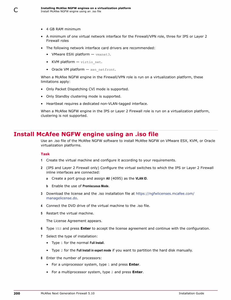
• 4 GB RAM minimum
• A minimum of one virtual network interface for the Firewall/VPN role, three for IPS or Layer 2Firewall roles
• The following network interface card drivers are recommended:
• VMware ESXi platform — vmxnet3.
• KVM platform — virtio_net.
• Oracle VM platform — xen_netfront.
When a McAfee NGFW engine in the Firewall/VPN role is run on a virtualization platform, theselimitations apply:
• Only Packet Dispatching CVI mode is supported.
• Only Standby clustering mode is supported.
• Heartbeat requires a dedicated non-VLAN-tagged interface.
When a McAfee NGFW engine in the IPS or Layer 2 Firewall role is run on a virtualization platform,clustering is not supported.
Install McAfee NGFW engine using an .iso fileUse an .iso file of the McAfee NGFW software to install McAfee NGFW on VMware ESX, KVM, or Oraclevirtualization platforms.
Task
1 Create the virtual machine and configure it according to your requirements.
2 (IPS and Layer 2 Firewall only) Configure the virtual switches to which the IPS or Layer 2 Firewallinline interfaces are connected:
a Create a port group and assign All (4095) as the VLAN ID.
b Enable the use of Promiscuous Mode.
3 Download the license and the .iso installation file at https://ngfwlicenses.mcafee.com/managelicense.do.
4 Connect the DVD drive of the virtual machine to the .iso file.
5 Restart the virtual machine.
The License Agreement appears.
6 Type YES and press Enter to accept the license agreement and continue with the configuration.
7 Select the type of installation:
• Type 1 for the normal Full Install.
• Type 2 for the Full Install in expert mode if you want to partition the hard disk manually.
8 Enter the number of processors:
• For a uniprocessor system, type 1 and press Enter.
• For a multiprocessor system, type 2 and press Enter.
C Installing McAfee NGFW engines on a virtualization platformInstall McAfee NGFW engine using an .iso file
200 McAfee Next Generation Firewall 5.10 Installation Guide

9 Continue in one of the following ways:
• If you selected Full Install, type YES and press Enter to accept automatic hard disk partitioning.
• If you selected Full Install in expert mode, install the engine in expert mode.
The installation process starts.
Install McAfee NGFW engine using a VMDK imageUse a VMDK image to install McAfee NGFW on OpenStack and Windriver virtualization platforms.
For platform-specific instructions, see the product documentation for the virtualization platform.
Task1 Create the virtual machine and configure it according to your requirements.
2 Download the license and the VMDK image at https://ngfwlicenses.mcafee.com/managelicense.do.
3 Convert the VMDK image for use as a hard disk.
4 Assign the converted hard disk to the virtual machine.
Installing McAfee NGFW engines on a virtualization platformInstall McAfee NGFW engine using a VMDK image C
McAfee Next Generation Firewall 5.10 Installation Guide 201

C Installing McAfee NGFW engines on a virtualization platformInstall McAfee NGFW engine using a VMDK image
202 McAfee Next Generation Firewall 5.10 Installation Guide
D Installing McAfee NGFW engines onthird-party hardware
You can install the McAfee NGFW engine software on third-party hardware that meets the hardwarerequirements.
Contents Hardware requirements for installing McAfee NGFW engines on third-party hardware Start the McAfee NGFW engine installation on third-party hardware Install McAfee NGFW in expert mode
Hardware requirements for installing McAfee NGFW engines onthird-party hardware
There are some basic hardware requirements when you run McAfee NGFW engines on third-partyhardware.
Check that the Automatic Power Management (APM) and Advanced Configuration and Power Interface(ACPI) settings are disabled in BIOS. Otherwise, the engine might not start after installation or can shutdown unexpectedly.
The engines must be dedicated to the McAfee NGFW. No other software can be installed on them.
The following basic hardware requirements apply:
• (Recommended for new deployments) Intel® Xeon®-based hardware from the E5-16xx productfamily or higher
Legacy deployments with Intel® Core™2 are supported.
• IDE hard disk and CD drive
IDE RAID controllers are not supported.
• Memory:
• 4 GB RAM minimum for x86-64-small installation
• 8 GB RAM minimum for x86-64 installation
• VGA-compatible monitor and keyboard
• One or more certified network interfaces for the Firewall/VPN role
McAfee Next Generation Firewall 5.10 Installation Guide 203

• Two or more certified network interfaces for IPS with IDS configuration
• Three or more certified network interfaces for Inline IPS or Layer 2 Firewall
Network interface cardsMcAfee NGFW supports Ethernet, Fast Ethernet, Gigabit, and 10-Gigabit Ethernet interfaces on theIntel platform.
We strongly recommend using network interface cards (NIC) that McAfee has certified. For informationabout certified network interface cards, see KB78844.
Hardware driversWe recommend using the listed approved drivers supported by McAfee NGFW.
Tested network interface card drivers included in the kernel of McAfee NGFW are listed in the followingtable. These drivers have been tested for use in McAfee NGFW.
Table D-1 Tested network interface card drivers
Driver Version Description
e1000e.ko 2.3.2-k Intel® PRO/1000 Network Driver
e1000x.ko 7.3.21-k8-NAPI Intel® PRO/1000 Network Driver
i40e.ko 1.2.37+sg2 Intel® Ethernet Connection XL710 Network Driver
igb.ko 5.1.2+sg7+s1 Intel® Gigabit Ethernet Network Driver
ixgbe.ko 3.14.5+sg10 Intel® 10 Gigabit PCI Express Network Driver
virtio_net.ko No version Virtio network driver
vmxnet3.ko 1.2.0.0-k VMware vmxnet3 virtual NIC driver
xen-netfront.ko No version Xen virtual network device frontend
Other network interface card drivers included in the kernel of McAfee NGFW are listed in the followingtable. All drivers are the driver version that is included in the standard Linux 3.16.7 kernel.
These drivers have not been tested for use in McAfee NGFW.
Table D-2 Other network interface card drivers
Driver Description
3c59x.ko 3Com 3c59x/3c9xx Ethernet driver
8139cp.ko RealTek RTL-8139C+ series 10/100 PCI Ethernet Driver
8139too.ko RealTek RTL-8139 Fast Ethernet Driver
8390.ko No description
acenic.ko AceNIC/3C985/GA620 Gigabit Ethernet Driver
amd8111e.ko AMD8111 based 10/100 Ethernet Controller. Driver Version 3.0.7
atl1.ko Atheros L1 Gigabit Ethernet Driver
atl1e.ko Atheros 1000M Ethernet Network Driver
b44.ko Broadcom 44xx/47xx 10/100 PCI Ethernet Driver
be2net.ko Emulex OneConnect NIC Driver 10.2u
bnx2.ko Broadcom NetXtreme II BCM5706/5708/5709/5716 Driver
bnx2x.ko Broadcom NetXtreme II BCM57710/57711/57711E/57712/ 57712_MF/57800/57800_MF/57810/57810_MF/57840/57840_MF Driver
D Installing McAfee NGFW engines on third-party hardwareHardware requirements for installing McAfee NGFW engines on third-party hardware
204 McAfee Next Generation Firewall 5.10 Installation Guide

Table D-2 Other network interface card drivers (continued)
Driver Description
tg3.ko Broadcom Tigon3 Ethernet Driver
cxgb.ko Chelsio 10 Gb Ethernet Driver
cxgb3.ko Chelsio T3 Network Driver
cxgb4.ko Chelsio T4/T5 Network Driver
dl2k.ko D-Link DL2000-based Gigabit Ethernet Adapter
dmfe.ko Davicom DM910X fast Ethernet Driver
e100.ko Intel® PRO/100 Network Driver
epic100.ko SMC 83c170 EPIC series Ethernet Driver
fealnx.ko Myson MTD-8xx 100/10M Ethernet PCI Adapter Driver
forcedeth.ko Reverse Engineered nForce Ethernet Driver
hamachi.ko Packet Engines 'Hamachi' GNIC-II Gigabit Ethernet Driver
hp100.ko HP CASCADE Architecture Driver for 100VG-AnyLan Network Adapters
i40e_ik.ko Intel® Ethernet Connection XL710 Network Driver
igb_ik.ko Intel® Gigabit Ethernet Network Driver
ipg.ko IC Plus IP1000 Gigabit Ethernet Adapter Linux Driver
ixgb.ko Intel® PRO/10GbE Network Driver
ixgbe_ik.ko Intel® 10 gigabit PCI Express Network Driver
mdio.ko Generic support for MDIO-compatible transceivers
mii.ko MII hardware support library
mlx4_core.ko Mellanox ConnectX HCA low-level driver
mlx4_en.ko Mellanox ConnectX HCA Ethernet Driver
myri10ge.ko Myricom 10G driver (10GbE)
natsemi.ko National Semiconductor DP8381x series PCI Ethernet Driver
ne2k-pci.ko PCI NE2000 clone driver
netxen_nic.ko QLogic/NetXen (1/10) GbE Intelligent Ethernet Driver
niu.ko NIU Ethernet Driver
ns83820.ko National Semiconductor DP83820 10/100/1000 driver
pcnet32.ko Driver for PCnet32 and PCnetPCI based ether cards
qla3xxx.ko QLogic ISP3XXX Network Driver v2.03.00-k5
r6040.ko RDC R6040 NAPI PCI Fast Ethernet Driver
r8169.ko RealTek RTL-8169 Gigabit Ethernet Driver
s2io.ko No description
sc92031.ko Silan SC92031 PCI Fast Ethernet Adapter Driver
sis190.ko SiS sis190/191 Gigabit Ethernet Driver
sis900.ko SiS 900 PCI Fast Ethernet Driver
skge.ko SysKonnect Gigabit Ethernet Driver
sky2.ko Marvell Yukon 2-Gigabit Ethernet Driver
starfire.ko Adaptec Starfire Ethernet Driver
sundance.ko Sundance Alta Ethernet driver
Installing McAfee NGFW engines on third-party hardwareHardware requirements for installing McAfee NGFW engines on third-party hardware D
McAfee Next Generation Firewall 5.10 Installation Guide 205

Table D-2 Other network interface card drivers (continued)
Driver Description
sungem.ko Sun GEM Gbit Ethernet Driver
sunhme.ko Sun HappyMealEthernet(HME) 10/100baseT Ethernet Driver
tehuti.ko Tehuti Networks® Network Driver
tg3.ko Broadcom Tigon3 ethernet driver
tulip.ko Digital 21*4* Tulip Ethernet Driver
typhoon.ko 3Com Typhoon Family (3C990, 3CR990, and variants)
uli526x.ko ULi M5261/M5263 fast Ethernet Driver
via-rhine.ko VIA Rhine PCI Fast Ethernet driver
via-velocity.ko VIA Networking Velocity Family Gigabit Ethernet Adapter Driver
winbond-840.ko Winbond W89c840 Ethernet driver
yellowfin.ko Packet Engines Yellowfin G-NIC Gigabit Ethernet Driver
SCSI drivers included in the kernel of McAfee NGFW are listed in the following table. All drivers are thedriver version that is included in the standard Linux 3.16.7 kernel.
Not all included drivers have been tested for use in McAfee NGFW.
Table D-3 SCSI drivers
Driver Description
3Ware 9xxx SATA_RAID [CONFIG_SCSI_3W_9XXX]
Adaptec / IBM ServeRAID [CONFIG_SCSI_IPS]
Adaptec AACRAID [CONFIG_SCSI_AACRAID]
Adaptec I2O RAID [CONFIG_SCSI_DPT_I2O]
Adaptec SAS/SATA 3Gb/s [CONFIG_SCSI_AIC94X]
Adaptec Ultra160 [CONFIG_SCSI_AIC7XXX]
BusLogic MultiMaster and FlashPoint SCSI [CONFIG_SCSI_BUSLOGIC]
Domex DMX3191D SCSI [CONFIG_SCSI_DMX3191D]
Fusion MPT ScsiHost for FC/SPI/SAS [CONFIG_FUSION_FC/SPI/SAS]
Initio INIA100 SCSI [CONFIG_SCSI_INIA100]
Intel PIIX/ICH PATA/SATA [CONFIG_ATA_PIIX]
LSI Logic MegaRAID (Legacy) [CONFIG_MEGARAID_LEGACY]
LSI Logic MegaRAID (NEWGEN) [CONFIG_MEGARAID_NEWGEN]
LSI Logic MegaRAID (SAS) [CONFIG_MEGARAID_SAS]
NVIDIA nForce SATA [CONFIG_SATA_NV]
Pacific Digital ADMA [CONFIG_PDC_ADMA]
Promise SATA [CONFIG_SATA_SX4]
Promise SATA TX2/TX4 [CONFIG_SATA_PROMISE]
QLogic IPS2x00 [CONFIG_SCSI_QLA2XXX]
QLogic ISP1240/1x80/1x160/1020/1040 SCSI [CONFIG_SCSI_QLOGIC_1280]
ServerWorks / Apple K2 SATA [CONFIG_SATA_SVW]
Silicon Image 3124/3132 SATA [CONFIG_SATA_SIL24]
D Installing McAfee NGFW engines on third-party hardwareHardware requirements for installing McAfee NGFW engines on third-party hardware
206 McAfee Next Generation Firewall 5.10 Installation Guide
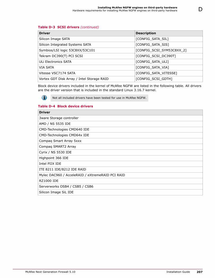
Table D-3 SCSI drivers (continued)
Driver Description
Silicon Image SATA [CONFIG_SATA_SIL]
Silicon Integrated Systems SATA [CONFIG_SATA_SIS]
Symbios/LSI logic 53C8XX/53C101 [CONFIG_SCSI_SYM53C8XX_2]
Tekram DC390(T) PCI SCSI [CONFIG_SCSI_DC390T]
ULi Electronics SATA [CONFIG_SATA_ULI]
VIA SATA [CONFIG_SATA_VIA]
Vitesse VSC7174 SATA [CONFIG_SATA_VITESSE]
Vortex GDT Disk Array / Intel Storage RAID [CONFIG_SCSI_GDTH]
Block device drivers included in the kernel of McAfee NGFW are listed in the following table. All driversare the driver version that is included in the standard Linux 3.16.7 kernel.
Not all included drivers have been tested for use in McAfee NGFW.
Table D-4 Block device drivers
Driver
3ware Storage controller
AMD / NS 5535 IDE
CMD-Technologies CMD640 IDE
CMD-Technologies CMD64x IDE
Compaq Smart Array 5xxx
Compaq SMART2 Array
Cyrix / NS 5530 IDE
Highpoint 366 IDE
Intel PIIX IDE
ITE 8211 IDE/8212 IDE RAID
Mylec DAC960 / AcceleRAID / eXtremeRAID PCI RAID
RZ1000 IDE
Serverworks OSB4 / CSB5 / CSB6
Silicon Image SiL IDE
Installing McAfee NGFW engines on third-party hardwareHardware requirements for installing McAfee NGFW engines on third-party hardware D
McAfee Next Generation Firewall 5.10 Installation Guide 207
Start the McAfee NGFW engine installation on third-partyhardware
After configuring the engine elements in the SMC, begin installing the McAfee NGFW engine softwareon your own hardware.
Before you beginBefore you start installing the McAfee NGFW engine, make sure that you have the initialconfiguration and a one-time password for management contact for each engine. Theseitems are generated in the SMC.
Installing the McAfee NGFW engine software deletes all existing data on the hard disk.
Depending on your order, you might have received ready-made SMC and McAfee NGFW engine DVDs.If the DVDs are not included in the order, you must first create them.
Task
1 Insert the engine installation DVD into the drive and restart the system.
The License Agreement appears.
2 Type YES and press Enter to accept the license agreement and continue with the configuration.
3 Select the type of installation:
• Type 1 for the normal Full Install.
• Type 2 for the Full Install in expert mode if you want to partition the hard disk manually.
4 Enter the number of processors:
• For a uniprocessor system, type 1 and press Enter.
• For a multiprocessor system, type 2 and press Enter.
5 Continue in one of the following ways:
• If you selected Full Install, type YES and press Enter to accept automatic hard disk partitioning.
• If you selected Full Install in expert mode, install the engine in expert mode.
The installation process starts.
Install McAfee NGFW in expert modeYou can install McAfee NGFW in expert mode if you want to partition the hard disk manually. If you areunfamiliar with partitioning hard disks in Linux, use the normal installation process.
When using the command prompt, use the reboot command to reboot and halt command to shutdown the node. Do not use the init command. You can also reboot the node using the ManagementClient.
Tasks• Partition the hard disk in expert mode on page 209
Typically, you need five partitions for an engine.
• Allocate partitions in expert mode on page 209After partitioning the hard disk, assign the partitions for the engine.
D Installing McAfee NGFW engines on third-party hardwareStart the McAfee NGFW engine installation on third-party hardware
208 McAfee Next Generation Firewall 5.10 Installation Guide
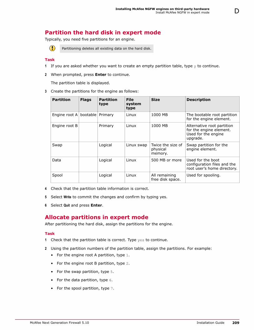
Partition the hard disk in expert modeTypically, you need five partitions for an engine.
Partitioning deletes all existing data on the hard disk.
Task1 If you are asked whether you want to create an empty partition table, type y to continue.
2 When prompted, press Enter to continue.
The partition table is displayed.
3 Create the partitions for the engine as follows:
Partition Flags Partitiontype
Filesystemtype
Size Description
Engine root A bootable Primary Linux 1000 MB The bootable root partitionfor the engine element.
Engine root B Primary Linux 1000 MB Alternative root partitionfor the engine element.Used for the engineupgrade.
Swap Logical Linux swap Twice the size ofphysicalmemory.
Swap partition for theengine element.
Data Logical Linux 500 MB or more Used for the bootconfiguration files and theroot user’s home directory.
Spool Logical Linux All remainingfree disk space.
Used for spooling.
4 Check that the partition table information is correct.
5 Select Write to commit the changes and confirm by typing yes.
6 Select Quit and press Enter.
Allocate partitions in expert modeAfter partitioning the hard disk, assign the partitions for the engine.
Task1 Check that the partition table is correct. Type yes to continue.
2 Using the partition numbers of the partition table, assign the partitions. For example:
• For the engine root A partition, type 1.
• For the engine root B partition, type 2.
• For the swap partition, type 5.
• For the data partition, type 6.
• For the spool partition, type 7.
Installing McAfee NGFW engines on third-party hardwareInstall McAfee NGFW in expert mode D
McAfee Next Generation Firewall 5.10 Installation Guide 209

3 Check the partition allocation and type yes to continue.
The engine installation starts.
4 When installation is complete, remove the DVD from the system and press Enter to reboot.
See also Configure McAfee NGFW engine software using automatic configuration on page 132Configure McAfee NGFW engine software with the McAfee NGFW Configuration Wizard on page132
D Installing McAfee NGFW engines on third-party hardwareInstall McAfee NGFW in expert mode
210 McAfee Next Generation Firewall 5.10 Installation Guide

E Example network (Firewall/VPN)
This example gives you a better understanding of how McAfee NGFW in the Firewall/VPN role fits intoa network.
The example outlines a network with two firewalls: a Single Firewall at a branch office and a FirewallCluster at headquarters.
Contents Example Firewall Cluster Example Single Firewall Example headquarters management network
McAfee Next Generation Firewall 5.10 Installation Guide 211

Example Firewall ClusterThis example shows Firewall Cluster interfaces in the example network.
In the example network, the HQ Firewall Cluster is located in the Headquarters network. The clusterconsists of two cluster nodes: Node 1 and Node 2.
Figure E-1 Example firewall scenario
Network Description
Heartbeat network The heartbeat and cluster synchronization goes through the heartbeat network.CVI: no CVI defined.
NDI: 10.42.1.1 (Node 1) and 10.42.1.2 (Node 2).
Managementnetwork (DMZ)
The management network interface is used for the control connections fromthe Management Server and for connecting to the HQ Log Server.CVI: 192.168.10.1.
NDI: 192.168.10.21 (Node 1) and 192.168.10.22 (Node 2).
E Example network (Firewall/VPN)Example Firewall Cluster
212 McAfee Next Generation Firewall 5.10 Installation Guide

Network Description
ISP A externalnetwork
This connection is one of the 2 Internet connections from the Headquarterssite. It is provided by ISP A.CVI: 212.20.1.254.
NDI: 212.20.1.21 (Node 1) and 212.20.1.22 (Node 2).
Next hop router: 212.20.1.1.
ISP B externalnetwork
This connection is the other of the 2 Internet connections from theHeadquarters site. It is provided by ISP B.CVI: 129.40.1.254.
NDI: 129.40.1.21 (Node 1) and 129.40.1.22 (Node 2).
Next hop router: 129.40.1.1.
HQ intranet This VLAN (VLAN ID 16) is connected to the same network interface on thefirewall with the HQ Accounting VLAN.CVI: 172.16.1.1.
NDI: 172.16.1.21 (Node 1) and 172.16.1.22 (Node 2).
HQ Accountingnetwork
This VLAN (VLAN ID 17) is connected to the same network interface on thefirewall with the HQ intranet VLAN.CVI: 172.17.1.1.
NDI: 172.17.1.21 (Node 1) and 172.17.1.22 (Node 2).
The Management Server and the HQ Log Server are at the headquarters site, in the DMZ network.
Security ManagementCenter (SMC)component
Description
Management Server This Management Server manages all firewalls and Log Servers of theexample network.
The Management Server in the Headquarters’ Management Network(DMZ) with the IP address 192.168.1.101.
HQ Log Server This Log Server receives log data from the firewalls.
The server is located in the Headquarters’ Management Network (DMZ)with the IP address 192.168.1.102.
Example network (Firewall/VPN)Example Firewall Cluster E
McAfee Next Generation Firewall 5.10 Installation Guide 213

Example Single FirewallThe Branch Office firewall is a Single Firewall located in the Branch Office network.
Figure E-2 Example Single Firewall
Example headquarters management networkThis example shows a sample management network.
Figure E-3 Example HQ management network
E Example network (Firewall/VPN)Example Single Firewall
214 McAfee Next Generation Firewall 5.10 Installation Guide

1 Internet 5 Switch
2 HQ firewall 6 Management Server 192.168.10.200
3 192.168.10.1 7 HQ Log Server 192.168.10.201
4 212.20.1.254
HQ firewallThe HQ firewall provides NAT for the headquarters management network.
The HQ Firewall uses the following IP addresses with the headquarters management network:
• Internal: 192.168.10.1
• External: 212.20.1.254
SMC ServersThe example network includes a Management Server and a Log Server.
The following SMC Servers are included in the example network.
SMC Server Description
Management Server The Management Server is located in the headquarters’ management networkwith the IP address 192.168.10.200. This Management Server manages all IPSengines, Firewalls, and Log Servers of the example network.
HQ Log Server This server is located in the headquarters’ management network with the IPaddress 192.168.10.201. This Log Server receives alerts, log data, and eventdata from the DMZ IPS and from the HQ IPS Cluster
Example network (Firewall/VPN)Example headquarters management network E
McAfee Next Generation Firewall 5.10 Installation Guide 215

E Example network (Firewall/VPN)Example headquarters management network
216 McAfee Next Generation Firewall 5.10 Installation Guide

F Example network (IPS)
To give you a better understanding of how McAfee NGFW in the IPS role fits into a network, thisexample outlines a network with IPS engines.
Contents Example network overview (IPS) Example headquarters intranet network HQ IPS Cluster Example headquarters DMZ network
Example network overview (IPS)This example network environment is used in all IPS examples.
There are two example IPS installations:
• An IPS Cluster in the Headquarters intranet network.
• A Single IPS in the Headquarters DMZ network.
Figure F-1 Example network
McAfee Next Generation Firewall 5.10 Installation Guide 217

1 HQ firewall 5 HQ intranet 172.16.1.0/24
2 Branch office firewall 6 HQ Management 192.168.10.0/24
3 HQ DMZ 192.168.1.0/24 7 Branch Office intranet 172.16.1.0/24
4 Internet
Example headquarters intranet networkThis example shows a sample headquarters intranet network.
Figure F-2 Example headquarters intranet network.
HQ IPS ClusterIn this example, the HQ IPS Cluster is an inline serial cluster located in the Headquarters network.
The cluster consists of two IPS engine nodes: Node 1 and Node 2.
Networkinterface
Description
CaptureInterfaces
The HQ IPS Cluster’s capture interface on each node is connected to a SPAN port inthe headquarters intranet switch. All traffic in this network segment is forwarded tothe SPAN ports for inspection.
Inline Interfaces The cluster is deployed in the path of traffic between the firewall and theheadquarters intranet switch. All traffic flows through each node’s Inline Interfacepair.
NormalInterfaces
The normal interface on each node is connected to the headquarters intranetswitch. Node 1’s IP address is 172.16.1.41 and Node 2’s address is 172.16.1.42.This normal interface is used for control connections from the Management Server,sending events to the HQ Log Server, and for sending TCP resets
HeartbeatInterfaces
The nodes have dedicated Heartbeat Interfaces. Node 1 uses the IP address10.42.1.41 and Node 2 uses the IP address 10.42.1.42.
F Example network (IPS)Example headquarters intranet network
218 McAfee Next Generation Firewall 5.10 Installation Guide

Example headquarters DMZ networkThis example shows a sample DMZ network.
Figure F-3 Example headquarters DMZ network
1 DMZ servers
2 192.168.1.41
3 HQ Firewall 192.168.1.1
DMZ IPSIn this example, the DMZ IPS in the headquarters DMZ network is a single inline IPS engine.
Networkinterface
Description
Inline Interfaces The DMZ IPS is deployed in the path of traffic between the firewall and the DMZnetwork switch. All traffic flows through the IPS engine’s inline interface pair.
NormalInterfaces
The normal interface is connected to the DMZ network using the IP address192.168.1.41. This normal interface is used for control connections from theManagement Server, sending event information to the HQ Log Server, and for TCPconnection termination.
Example network (IPS)Example headquarters DMZ network F
McAfee Next Generation Firewall 5.10 Installation Guide 219

F Example network (IPS)Example headquarters DMZ network
220 McAfee Next Generation Firewall 5.10 Installation Guide

G Cluster installation worksheetinstructions
For planning the configuration of network interfaces for the engine nodes, use the worksheet.
• Interface ID — Write the Interface ID (and the VLAN ID, if VLAN tagging is used).
• CVI — Write the Interface ID’s CVI information (if any) and on the NDI line, write the interfaces NDIinformation (if any). Use multiple lines for an Interface ID if it has multiple CVIs/NDIs defined.
• Mode — Select all modes that apply for this Interface ID.
• IP Address and Netmask — Define the CVI or NDI network address.
• MAC/IGMP IP Address — Define the MAC address used. If the interface’s CVI Mode is Multicast withIGMP, define the multicast IP address used for generating automatically the multicast MAC address.
• Comments — Define, for example, a name of the connected network. Show how the NDI addressesdiffer between the nodes. Define a management interface’s contact address if different from theinterface’s IP address.
Interface modes are explained in the following table. These same character codes are displayed in thefirewall element interface properties of the Management Client.
Cluster installation worksheetThe following modes apply in the worksheet.
• CVI mode —: U=Unicast MAC, M=Multicast MAC, I=Multicast with IGMP, K=Packet Dispatch,A=Interface’s IP address used as the identity for authentication requests
• NDI modes — H=Primary heartbeat, h=Backup heartbeat, C=Primary control IP address,c=Backup control IP address, D=Default IP address for outgoing connection
InterfaceID Type Mode IP Address Netmask MAC / IGMP IP Address
CVI U M I K A ___ . ___ . ___ . ___ ___ . ___ . ___ . ___
MAC: ___ : ___ : ___ : ___ : ___ : ___or
IGMP IP: ___ . ___ . ___ . ___
NDI H h C c D ___ . ___ . ___ . ___ ___ . ___ . ___ . ___ MAC: ___ : ___ : ___ : ___ : ___ : ___
Comments
CVI U M I K A ___ . ___ . ___ . ___ ___ . ___ . ___ . ___
MAC: ___ : ___ : ___ : ___ : ___ : ___or
IGMP IP: ___ . ___ . ___ . ___
McAfee Next Generation Firewall 5.10 Installation Guide 221

InterfaceID Type Mode IP Address Netmask MAC / IGMP IP Address
NDI H h C c D ___ . ___ . ___ . ___ ___ . ___ . ___ . ___ MAC: ___ : ___ : ___ : ___ : ___ : ___
Comments
CVI U M I K A ___ . ___ . ___ . ___ ___ . ___ . ___ . ___
MAC: ___ : ___ : ___ : ___ : ___ : ___or
IGMP IP: ___ . ___ . ___ . ___
NDI H h C c D ___ . ___ . ___ . ___ ___ . ___ . ___ . ___ MAC: ___ : ___ : ___ : ___ : ___ : ___
Comments
CVI U M I K A ___ . ___ . ___ . ___ ___ . ___ . ___ . ___
MAC: ___ : ___ : ___ : ___ : ___ : ___or
IGMP IP: ___ . ___ . ___ . ___
NDI H h C c D ___ . ___ . ___ . ___ ___ . ___ . ___ . ___ MAC: ___ : ___ : ___ : ___ : ___ : ___
Comments
CVI U M I K A ___ . ___ . ___ . ___ ___ . ___ . ___ . ___
MAC: ___ : ___ : ___ : ___ : ___ : ___or
IGMP IP: ___ . ___ . ___ . ___
NDI H h C c D ___ . ___ . ___ . ___ ___ . ___ . ___ . ___ MAC: ___ : ___ : ___ : ___ : ___ : ___
Comments
CVI U M I K A ___ . ___ . ___ . ___ ___ . ___ . ___ . ___
MAC: ___ : ___ : ___ : ___ : ___ : ___or
IGMP IP: ___ . ___ . ___ . ___
NDI H h C c D ___ . ___ . ___ . ___ ___ . ___ . ___ . ___ MAC: ___ : ___ : ___ : ___ : ___ : ___
Comments
CVI U M I K A ___ . ___ . ___ . ___ ___ . ___ . ___ . ___
MAC: ___ : ___ : ___ : ___ : ___ : ___or
IGMP IP: ___ . ___ . ___ . ___
NDI H h C c D ___ . ___ . ___ . ___ ___ . ___ . ___ . ___ MAC: ___ : ___ : ___ : ___ : ___ : ___
Comments
G Cluster installation worksheet instructionsCluster installation worksheet
222 McAfee Next Generation Firewall 5.10 Installation Guide

Index
AAntispoofing 143
BBypassing traffic 98
CCapture interfaces 20
SPAN ports 20
Certificatemanagement server 49
Certificatesgenerating 51
server 51
Cluster interfacesconfiguring IP addresses 81
command line 175
commandsSMC 175
SMC Appliance 175
Configurationfrom the command line 44–46
log server 45
management server 44
web portal server 46
conventions and icons used in this guide 9
DDefault route
addingmulti-link 140
documentationaudience for this guide 9product-specific, finding 10
typographical conventions and icons 9Dynamic IP address
defining contact addresses 73
Dynamic IP addressesconfiguring
setting up PPP 73
EEngine element
Layer 2 firewalls 102
FFirewall cluster
adding elements 79
adding physical interfaces 80
global interface options 84
Firewall clusters 77
add VLAN 81
adding an IPv4 address 82
adding nodes 79
binding licenses to elements 86
creating cluster elements 79
global interfacesARP entries 85
heartbeat connection 19
interface numbers 77
IP addresses 78
IPv6 address 83
modes 78
synchronization 19
Firewall engineinstalling
expert mode 208
Firewall enginesupdating
from a .zip file 164
upgrading 157
from a DVD 164
locally 163
Firewall licenses 28
installing 63
Firewall systemcomponents 15
Firewallscabling 21
installingthird-party hardware 203
McAfee Next Generation Firewall 5.10 Installation Guide 223

GGlobal interface options
firewall cluster 84
HHard disk
allocating partitions 209
partitioning 209
IInitial configuration
savingautomatic configuration 130
plug and play 128
with McAfee NGFW Configuration wizard 133
Initial policyinstalling 145
Installationadditional servers
management server 56
Demo mode 41
finishing 40
from the command line 42, 43
SMC 33, 42, 43
SMC components 36
Installation filesdownloading 27
obtaining 158
Installation process 29
interfacessystem communication 88, 102
Interfacesconfiguring
dynamic IP addresses 73
IP addresses 71
static IPv4 72
static IPv6 73
mapping IDs 136
VLANdefining 89
IP addresssingle IPS engine 90
IPSbinding licenses to elements 98
IPS clusterIP address
defining 92
IPS enginesdefining 87
engine elementcreate 88
interface options 93
physical interfaces 89
single
IPS engines
IP address 90
system communication interfaces 88
traffic inspection interfaces 94
capture interface 96
inline interface 97
logical interface 95
reset interface 96
VLAN interface 89
IPS networkexample 217
LLayer 2 firewall cluster
IP addresses 106
layer 2 firewallsbinding licenses to elements 112
system communication interfaces 102
Layer 2 firewallsdefining 101
engine elementcreating 102
interface options 107
IP address 104
physical interface 103
traffic inspection interfaces 108
capture interface 110
inline interface 111
logical interface 109
reset interface 109
VLAN interface 103
License filesobtaining 28
Licensesbinding 50
checking 161
firewall 28
generating 160
installing 49, 153
updatingone proof code 160
upgrading 152, 160
multiple proof codes 160
Log serverinstalling 39
MMaintaining the SMC 151
Management Clientdistribution
from a separate server 59
from SMC servers 58
setting location 55
starting 48
Index
224 McAfee Next Generation Firewall 5.10 Installation Guide

Management Client (continued)web start distribution 57
Management serverafter contact 137
contacting 137
starting 48
Master engineadd a physical interface 116
add node 115
Master engine clustersheartbeat connection 19
synchronization 19
Master enginesadd master engine elements 114
configuring 113
McAfee ServicePortal, accessing 10
NNAT addresses
configuring 53
defining locations 54
Network driversdefining 136
Network interfacesconfiguring 136
Network TAPs 20
NGFW engineconfiguring operating system settings 135
installingstarting 208
virtualization platform 200, 201
NGFW firewallconfiguring
Configuration wizard 132
installationusing USB drive 132
NGFW roleslicensing 28
PPolicies
creating 143
defining basic 143
ping rule 144
ready-made 147
Post-installation tasks 52
Pre-installationfile integrity 27
RRouting
add default routesingle network 140
antispoofing 143
Routing (continued)defining 139
other routes 142
SSecurity engines
command online 147
Security Management Centerinstalling components 36
uninstalling 155
upgrading 153
Serversstarting 51
starting manually 51
ServicePortal, finding product documentation 10
Settingsduplex 26
speed 26
Single firewallbinding licenses to elements 77
configuringadd single firewall element 65
adding a single firewall element 64
modem interfaces 75
setting global interface options 76
Single firewall elementADSL interface 67
creating 65
physical interface 66
selecting interface numbers 64
SSID interface 69
VLAN interface 67
wireless interface 68
Single firewallsconfiguring 64
SMCcommands 175
logging on 49
supported platforms 17
uninstalling 155
Linux 156
Windows 156
upgrading 151, 153
SMC Appliance 17
administrator logon 49
commands 175
SMC componentsconfiguring NAT addresses 53
installinglog server 39
management server 38
web portal server 40
SMC installation 33
Index
McAfee Next Generation Firewall 5.10 Installation Guide 225

SMC Installationon Linux 35
SMC servercontact addresses 55
SMC serversstart failures 51
troubleshooting 51
Startingmanagement Client 48
management server 48
Ttechnical support, finding product information 10
Trafficbypassing 98
Traffic inspection interfacesLayer 2 firewall 108
UUninstalling SMC 155
Upgrading SMCsynchronizing databases 154
Upgrading SMC (continued)upgrading licenses 152
VVirtual firewall
binding licenses to elements 120
physical interfaces 121
Virtual firewallsconfiguring 113
Virtual IPSconfiguring 113
Virtual IPS enginesphysical interfaces 125
Virtual layer 2 firewallsconfiguring 113
Virtual Layer 2 firewallsphysical interfaces 126
Index
226 McAfee Next Generation Firewall 5.10 Installation Guide

B00