news eplan - rittbul · eplan®, eplan electric p8®, eplan fluid
TRANSCRIPT

EPLAN NEWS for Version 2.1

Copyright © 2011 EPLAN Software & Service GmbH & Co. KG
EPLAN Software & Service GmbH & Co. KG assumes no liability for either technical or printing errors, or for deficiencies in this technical information and cannot be held liable for damages that may result directly or indirectly from the delivery, performance, and use of this material.
This document contains legally protected proprietary information that is subject to copyright. All rights are protected. This document or parts of this document may not be copied or reproduced by any other means without the prior consent of EPLAN Software & Service GmbH & Co. KG.
The software described in this document is subject to a licensing agreement. The use and reproduction of the software is only permitted within the framework of this agreement.
RITTAL® is a registered trademark of Rittal GmbH & Co. KG.
EPLAN®, EPLAN Electric P8®, EPLAN Fluid®, EPLAN PPE®, EPLAN Cabinet®, EPLAN Pro Panel® and EPLAN Mechatronic Integration® are registered trademarks of EPLAN Software & Service GmbH & Co. KG.
Windows NT®, Windows 2000®, Windows XP®, Windows Vista®, Windows 7®, Microsoft Windows®, Microsoft® Excel®, Microsoft® Access® and Notepad® are registered trademarks of the Microsoft Corporation.
PC WORX®, CLIP PROJECT®, and INTERBUS® are registered trademarks of Phoenix Contact GmbH & Co.
AutoCAD® and AutoCAD Inventor® are registered trademarks of Autodesk, Inc.
STEP 7®, SIMATIC® and SIMATIC HW Konfig.® are registered trademarks of Siemens AG.
InstallShield® is a registered trademark of InstallShield, Inc.
Adobe® Reader® and Adobe® Acrobat® are registered trademarks of Adobe Systems Inc.
TwinCAT® is a registered trademark of Beckhoff Automation GmbH.
Unity Pro® is a registered trademark of Schneider Electric.
RSLogix 5000® and RSLogix Architect® are registered trademarks of Rockwell Automation.
All other product names and trade names are trademarks or registered trademarks of their respective owners.
EPLAN uses the Open Source software 7-Zip (7za.dll), Copyright © by Igor Pavlov. The source code of 7-Zip is subject to the GNU Lesser General Public License (LGPL). The source code of 7-Zip and details on this license can be found on the following Web site: http://www.7-zip.org
EPLAN uses the open-source software Open CASCADE, Copyright © by Open CASCADE S.A.S. The source code of Open CASCADE is subject to the Open CASCADE Technology Public License. The source code of Open CASCADE and details on this license can be found on the following Web site: http://www.opencascade.org
Table of contents
EPLAN NEWS 2.1 3
Table of contents Preface ................................................................................................................... 9
Notes for the reader ........................................................................................... 10
New features of the entire EPLAN platform ....................................... 12
Project data navigators ....................................................................................... 12 Delete functions in the navigators ...................................................................... 12
More transparent view of the tree view ............................................................... 14
Improved column sorting in list views ................................................................. 14
Connections ......................................................................................................... 15 Extensions for the connection navigator ............................................................. 15
Filter connections according to source and target properties ............................. 17
Renamed connection properties ......................................................................... 18
Synchronize connections .................................................................................... 18
Parts management .............................................................................................. 20 Update the parts database ................................................................................. 20
Renamed main nodes ........................................................................................ 20
New main node "Accessory placement" ............................................................. 22
Tree configuration for all main nodes ................................................................. 22
Renamed product groups ................................................................................... 24
New "Manufacturing" tab for allocating drilling patterns ..................................... 24
Attributes for cross-part data .............................................................................. 26
Jump functions in parts management ................................................................. 26
Synchronize cross-part data ............................................................................... 27
Message management ........................................................................................ 29 Check only completed messages ....................................................................... 29
Limitation of time-intensive check runs ............................................................... 30
Changed behavior of the selection-based display .............................................. 31
Deactivated check runs ...................................................................................... 31
Check run 001016 with modified behavior .......................................................... 32
Macros .................................................................................................................. 32 Update macros ................................................................................................... 32
New features in the "EPLAN Pro Panel" add-on ............................................... 36 Save 2D and 3D data in different macros ........................................................... 37
Define degree of detailing for the import of 3D graphical data ............................ 38
Rotate 3D view when changing viewpoints ........................................................ 41
Display mounting aids ........................................................................................ 41
New toolbar for the device logic ......................................................................... 41
Display and modify field size of mounting surfaces ............................................ 42

Table of contents
4 EPLAN NEWS 2.1
Generate mounting surfaces .............................................................................. 43
Model views with simplified representation ......................................................... 44
STEP export as a new extension ....................................................................... 45
Devices ................................................................................................................. 46 Move positions of parts entered on the device ................................................... 46
Graphical editor ................................................................................................... 47 Define output size for PDF export ...................................................................... 47
Display messages about connections in the graphical editor ............................. 50
Display of unplaced connections on the component .......................................... 51
Reports ................................................................................................................. 51 Simplified selection of the source project when generating a report to another project ................................................................................................... 51
List only used project symbols in symbol overview ............................................ 53
Start a consecutive number again at "1" ............................................................. 54
Placeholder objects ............................................................................................ 56 Simplified transfer of variables from properties .................................................. 56
Device selection .................................................................................................. 57 Easier selection from the accessory list ............................................................. 57
Block properties .................................................................................................. 57 New format element for device groups ............................................................... 57
New features in the "EPLAN Revision Management" add-on ......................... 59 Property comparison of connection definition points .......................................... 59
New features in the "EPLAN Project Options" add-on .................................... 60 Modify sections subsequently ............................................................................. 60
New features in the "EPLAN User Rights Management" add-on .................... 62 Update the rights management .......................................................................... 62
New interface to link to Autodesk Vault ............................................................ 64
User interface ...................................................................................................... 64 New shared menu item for data import .............................................................. 64 Property preview removed .................................................................................. 65
Navigator dialog for device properties removed ................................................. 65
Divide projects into defined working sections .................................. 66
Activate selection of defined working sections in a project ............................ 67
Define working sections for a project ............................................................... 69 Open projects with active selection of defined working sections ........................ 70
Display of defined working sections in the multi-user monitor ............................ 71
Define defined working sections as administrator ........................................... 71 Select editor ....................................................................................................... 72

Table of contents
EPLAN NEWS 2.1 5
Work temporarily in entire project ..................................................................... 72 Update connections ............................................................................................ 73
Generate reports for defined working sections ................................................ 73
New monitor for multi-user mode ....................................................... 75
Set up the multi-user monitor ............................................................................ 76
Define the settings for the multi-user monitor .................................................. 77
Use the multi-user monitor ................................................................................. 78 Possible steps .................................................................................................... 80
Performance improvements ................................................................ 81
Improved performance through optimized project database .......................... 81
Changed program behavior ................................................................................ 82
Special topics EPLAN Electric P8 ....................................................... 83
Terminals / plugs ................................................................................................. 83 Store parts for pins and busbar connection points ............................................. 83
Improved overview in the "Connections" tab ...................................................... 85
New features in the "EPLAN PLC & Bus Extension" add-on ........................... 87 Updated interfaces for exchanging data with PLC configuration systems .......... 87
Special topics EPLAN Fluid ................................................................ 89
Rotate and mirror symbols and macros ............................................................ 89 Rotate and mirror symbols ................................................................................. 89
Rotate and mirror macros ................................................................................... 92
Transformation point for symbol variants ............................................................ 93
New layer for internal working lines .................................................................. 93
New "EPLAN Operational Sequence" Add-on for operational sequence sheets .................................................................................. 95
Preconditions ...................................................................................................... 98 Settings for operational sequence sheets .......................................................... 99
Create functional diagrams .............................................................................. 101 Place functions in the diagram ......................................................................... 101
Place macros in the diagram ............................................................................ 102
Further information regarding the placement of symbol / macro graphics ........ 103
Insert values for scale and process sequences ................................................ 104
New representation type "Functional" ............................................................ 105 Global editing of properties ............................................................................... 105
Data synchronization between representation types ........................................ 106
Representation type for symbols ...................................................................... 106
Table of contents
6 EPLAN NEWS 2.1
Create GRAFCET diagrams .............................................................................. 106 Insert table of variables .................................................................................... 108
Insert GRAFCET elements ............................................................................... 108
Describing texts ................................................................................................ 110
New special characters for GRAFCET ............................................................. 111
Special Topics EPLAN PPE ............................................................... 112
Display the DT of PCT loop elements in the functional view ......................... 112
Filter in EPLAN View according to PI Code .................................................... 113
Automatic PCT loop numbering ....................................................................... 113
Sort in connection with the selection of PCT loops ....................................... 115
Synchronize structure identifiers automatically when inserting macros ..... 115
Draw extended DT adoption at PCT loop ........................................................ 116
Extended EPLAN PPE P&ID AutoCAD interface ............................................. 118
EPLAN Pro Panel Professional ......................................................... 119
Modularization of EPLAN Pro Panel Professional .......................................... 125
Manufacturing data for NC machines .............................................................. 128
Generate routing connections ......................................................................... 129 Method for routing connections ........................................................................ 129
Routing paths ................................................................................................... 130
Routing ranges ................................................................................................. 131
Wiring cut-outs ................................................................................................. 132
Routing path network ....................................................................................... 132
Display of the routing path view ........................................................................ 133
Routing connections ......................................................................................... 133
Routing connections in the connection navigator ............................................. 135
Bundling of routing connections ....................................................................... 136
Optimization of nets .......................................................................................... 136
Manufacturing data for wire fabrication machines ......................................... 138
Mounting list report ........................................................................................... 138 Forms for mounting lists ................................................................................... 139
Filter for relevant devices in the layout space navigator ................................... 140
Support with master data creation .................................................................. 140 Automatic enclosure interpretation ................................................................... 140
Base points as special mounting points for accessory placement .................... 141
Transfer a base point scheme .......................................................................... 142
Import and export of data ................................................................................. 142 Import data ....................................................................................................... 142
Export data ....................................................................................................... 143
Table of contents
EPLAN NEWS 2.1 7
Data transfer from EPLAN Cabinet .................................................................. 144 Data transfer from Cabinet projects .................................................................. 144
Data transfer of NC data................................................................................... 145
Data transfer of master data ............................................................................. 145
Data transfer of accessories ............................................................................. 146
New Features in the EPLAN Data Portal .......................................... 147
Create user-defined parts with the Endress+Hauser configurator ............... 152
Start the Rittal Therm configurator .................................................................. 154
Import parts from the shopping cart into the device list ............................... 155
Insert a specific macro variant ......................................................................... 156
New features in the "EPLAN API Extension" add-on ...................... 157
Start the program via command line parameters ........................................... 157
Other new features in the EPLAN API ............................................................. 158
New features in the master data ....................................................... 162
Master data: Symbols ....................................................................................... 162
Master data: Forms ........................................................................................... 167
Master data: Settings for messages and check runs ..................................... 168
Master data: Macros .......................................................................................... 169
Other new features and information ................................................. 172
Customer queries and messages .................................................................... 172
Validation code .................................................................................................. 175 Retrieving the validation code online ................................................................ 175
Installation ......................................................................................................... 177 Installation using the EPLAN Setup Manager ................................................... 177
Software requirements and approvals ............................................................ 183 General requirements ....................................................................................... 183
Operating systems ........................................................................................... 183
Microsoft products ............................................................................................ 184
SQL server ....................................................................................................... 184
Autodesk products ............................................................................................ 184
PDF redlining .................................................................................................... 184
PLC systems (PLC & bus extension) ............................................................... 184
Unsupported operating systems ....................................................................... 185
Other software that is no longer supported ...................................................... 185

Table of contents
8 EPLAN NEWS 2.1
Hardware requirements .................................................................................... 186 Workstation hardware requirements ................................................................. 186
Recommended workstation configuration......................................................... 186
Minimum net requirements ............................................................................... 187
Minimum multi-user requirements .................................................................... 187

Preface
EPLAN NEWS 2.1 9
Preface
Dear EPLAN users,
Modern product creation processes (PCP) in machines and plant
construction are shaped by requirements for fast and efficient project
processing. To live up to this trend, it is important to standardize engi-
neering tools as well as to avoid incompatible data formats and, thus,
interruptions in the interdisciplinary data flow.
The EPLAN platform as a continuous engineering solution ensures the
consistency of project data across disciplines and project phases, and
allows for a smooth integration of engineering into your entire PCP. The
result: Faster engineering results with improved quality in machine and
plant documentation.
We are delighted to introduce the new EPLAN platform 2.1 with this up-
date. The new version comes with innovative functions and integrated
system solutions and, thus, provides the decisive additional enhance-
ment in terms of continuity of the engineering process.
Most recent example: EPLAN Pro Panel Professional
What began with 3D mounting layout is now an integrative engineering
solution for the construction of enclosures and switchgear. Schematic
generation, enclosure layout, manufacturing integration and mounting
merge into a continuous solution – including more added value.
Derive sustained benefit from the large number of other highlights of the
EPLAN platform 2.1, and allow yourself to be amazed by the new possi-
bilities of your EPLAN software.
We wish you much success with your new EPLAN platform 2.1.
Your EPLAN Software & Service team

Preface
10 EPLAN NEWS 2.1
Notes for the reader Important information:
Before installing the new version please read the information in "Other
new features and information" from page 172 onwards. In particular
please read "Software requirements and approvals" on page 183.
When switching from older EPLAN versions to the current version,
you must also note that the installation now exhibits a modified beha-
vior and is now handled via a new installation program (see section
"Installation using the EPLAN Setup Manager" on page 177).
When you open old projects in the EPLAN version 2.1, these projects
will be updated. More information on this is provided in the section
"Improved performance through optimized project database" on
page 81.
If you want to use an "older" parts database, you will first have to up-
date such a parts database (see section "Update the parts database"
on page 20).
If you use Rights management, you must update it when switching
to version 2.1. More information on this is provided in the section
"Update the rights management" on page 62.
Before you begin reading, please note the following symbols and styles
used in this document:
Warning:
Text preceded by this symbol contains a warning; you should be abso-
lutely sure to read this warning before proceeding!
Note:
Text preceded by this image contains extra notes.
Example:
Examples are highlighted by this symbol.

Preface
EPLAN NEWS 2.1 11
Tip:
Useful tips to facilitate your interaction with the program are presented
after this image. User interface elements are marked in bold (and blue) so they can
immediately be located in the text.
Italic text provides particularly important information that you should
definitely pay attention to.
Code examples, directory names, and direct input (among other ele-ments) are displayed in a non-proportional font.
Function keys, keyboard keys, and buttons within the program are
shown in square brackets (e.g., [F1] for the "F1" function key).
To improve the flow of the text, we often use "menu paths" in this
document (for example, Help > Contents). In order to find a particular
program function, the menus and options shown in a menu path must
be selected in the sequence shown. For example, the menu path
mentioned above calls up the EPLAN help system.
In combination with settings or fields (e.g., check boxes) which can
only be switched on or off, in this document we often use the term
"activate" (after which the setting is active ) and "deactivate" (after
which the setting is inactive ).

New features of the entire EPLAN platform
12 EPLAN NEWS 2.1
New features of the entire EPLAN platform
Project data navigators
Delete functions in the navigators
The delete function in the navigators now works exactly like that of the
graphical editor. Using the Delete popup menu item, you can now also
delete placed functions / objects in the navigators.
Benefit: Deleting is now easier and faster for you thanks to this stan-
dardization of the function in the navigators. When editing, you
do not have to switch between a navigator and the graphical
editor to delete a placed function. This working method saves
time, boosts project quality, and facilitates the path to profes-
sional database-specific engineering.
The selected functions are deleted following a confirmation prompt. If
you have selected a level in a tree, all functions below the selected level
will be deleted. Both placed and unplaced functions will be deleted.
When a placed function is deleted, the placing is also deleted at the
same time in the graphical editor or layout space.
Note:
Please note that when deleting placed functions, the existing connec-
tions in the projects can also be modified. New connections can arise
or connections can be deleted.
The new Delete popup menu item has been added to the potential and
interruption point navigator. Via this menu item, the selected objects
(potential definitions, etc.) and interruption points are removed according
to the previous description.

New features of the entire EPLAN platform
EPLAN NEWS 2.1 13
Navigators for devices / parts:
The Delete popup menu item has also been newly added to the 2D panel
layout and 3D mounting layout navigators. Here, this menu item only de-
letes part placements.
This means that the menu item can be executed only for part place-
ments. The selected part placements are deleted following a confirma-
tion prompt. The parts and functions are preserved.
In the bill of materials navigator, Delete – as before – is used to delete
the selected part references.
Delete placement of a function
Now you can also delete a placed function via Edit > Delete placement
even if you have not opened the graphical editor. This way, you can now
delete the graphical placements in the schematic from within a navigator.
Following a prompt, the placements of the selected objects will be de-
leted.
The Delete placement menu item has no effect on the objects in the
navigators for devices / parts (bills of materials, 2D panel layout navi-
gator, etc.), objects in the layout space navigator and in the 3D view of
an opened layout space. These navigators are used to manage part
placements, rather than placed or unplaced functions.
Note:
The settings for these functions in Rights management can be found in
the Rights list below the Graphical editor / Navigator topic area. The
rights for deleting functions and other objects are called Delete in graph-
ical editor and Delete in navigators. Deleting a placement is made
possible by the Delete placement right. If certain editing rights are re-
voked from a user group, the associated menu items will be grayed out.

New features of the entire EPLAN platform
14 EPLAN NEWS 2.1
More transparent view of the tree view
Previously, tree views of navigators would list in the top position and one
by one all devices, terminal strips, etc. that were not arranged in a de-
fined project structure by means of structure identifiers. To render the
tree view of navigators more transparent in such a case, all "sequentially
numbered" devices, terminal strips, etc. with device tags are now sorted
in the Without structure identifier tree structure level.
Benefit: The more transparent tree views make it easier for you to
handle the project data navigators if extensive projects are
involved.
This tree structure level is displayed only in projects with an identifier
structure (e.g., IEC identifier structure); that is, it is not displayed in
sequentially numbered projects. The already familiar Without DT tree
structure level is sorted below the Without structure identifier tree
structure level. At this hierarchical level, the devices are displayed that
are also characterized by not having a device tag.
On account of the modified tree view, the display of the data is also up-
dated faster. In case of an object modification in the area of the sequen-
tially numbered devices, it is now only this branch that is updated, rather
than the entire tree.
Improved column sorting in list views
Improved column sorting in the list views of the navigators ensures that a
previous sorting to another column is maintained in the event of column
sorting.
Benefit: List views are especially helpful if you want to get a quick
table-format overview of the project data. The new column
sorting reduces the search processes to a minimum and, thus,
accelerates your project work.

New features of the entire EPLAN platform
EPLAN NEWS 2.1 15
Example:
You are in the connection navigator, and you have sorted the list of con-
nections in an ascending fashion from the first Source column. Then,
you click on the Connection color / number column. The list is now
sorted alphanumerically and in ascending fashion according to connec-
tion color / number. While for connections of the same connection color (e.g., BK), the entries in the Source column were previously arranged
randomly, these entries are now still sorted correctly (for BK, for example,
=EB3+ET1-X1:1, =EB3+ET1-X1:7, =EB3+ET1-X1:13, =EB3+ET2-A2:7,
etc.).
Connections
Extensions for the connection navigator
The connection navigator now also has a tree view. The tree view is
used to sort the connections on the basis of the structure identifiers of
the device structure. The connections are listed twice, once below the
source DT, and a second time below the target DT.

New features of the entire EPLAN platform
16 EPLAN NEWS 2.1
Benefit: The extended representation facilitates, also in extensive pro-
jects, the handling of connection data due to the structure and
improved transparency. Depending on the tasks at hand, se-
lect the optimal view (list or tree view) for this central project
data. Quick finding without long searches – thanks to the new
options for quick input of a filter – helps save additional, valua-
ble planning time.
In the tree, you will see for each connection (where available) the follow-
ing information:
Connection point designation of the source DT / target DT
Displayed DT of the cables / bundles
Connection color / number

New features of the entire EPLAN platform
EPLAN NEWS 2.1 17
Connection designation
Function definition of the connection
Displayed DT of the counter target.
Quick input filtering
There is also the additional option in the connection navigator now to
filter the connections by way of a quick input. For this purpose, you can
now use the new Value: <Property> field below the filter both in the tree
and list view.
You can use quick input in this field to quickly modify the value of a filter
criterion for a defined and selected filter. For further information on the
quick input, refer to the online help for this dialog.
Filter connections according to source and target properties
In the connection navigator, it is now also possible to filter the connec-
tions according to the properties of the source and / or target. For exam-
ple, this enables you to filter for connections that originate from a specific
device or terminate at a specific device.
To achieve this, the criteria selection for the filter of the connection navi-
gator has been extended. From the Criteria selection dialog, you can
select a filter criterion by choosing connection properties as well as the
two new hierarchy levels "Source or target" and "Source and target".
These two property lists have been realized in the filter as OR and AND
operations for performance reasons.

New features of the entire EPLAN platform
18 EPLAN NEWS 2.1
Output of the connection list
In the output of the connection list in the Filter / sorting - Connection
list dialog, too, you can now access the source and target properties for
the filter and sorting. The respective dialogs for the criteria selection
have also been extended accordingly.
Renamed connection properties
In order to differentiate between the connection properties Type of con-
nection (ID 31075) and Connection: Type (ID 31048) clearly, these
properties have now been renamed.
Old name: New name:
Type of connection Type of administration
Connection: Type Connection: Type designation The Type of administration of a connection (e.g., placed, unplaced, etc.)
indicates the way in which this connection is managed in EPLAN. The
property can be used to sort the connections in the connection navigator.
The Type designation of the connection part (e.g., the type number of the
type of wire, pipe or tubing) is entered in the Connection: Type desig-
nation property or imported by the selected part from parts manage-
ment.
Synchronize connections
A connection can occur in the schematic several times in the representa-
tion types "Multi-line", "Single-line", or "3D mounting layout". Connections
of the "3D mounting layout" representation type are called routing con-
nections. These are connections routed in a layout space.
New features of the entire EPLAN platform
EPLAN NEWS 2.1 19
If you have not activated the Properties (global) editing mode, then you
can edit the properties of the distributed connections independently of
one another. Differences between the connection properties will arise as
a result. If you want to remove the differences, you can synchronize the
properties of the distributed connections for the entire project.
The option to synchronize the data of functions displayed in a distributed
manner has existed in EPLAN for some time. For this reason, the
previous Synchronize menu item (under Utilities > Synchronize) has
been split into the two submenu items Functions and Connections.
The following two options exist for synchronizing distributed connections:
If you wish to import and apply the values of the selected multi-line
connections to the related connections of the other representation
types, select the following menu items: Utilities > Synchronize >
Connections > Multi-line --> all representation types.
To synchronize selected routing connections, select the following
menu items: Utilities > Synchronize > Connections > 3D mounting
layout --> all representation types.
Click [OK] to confirm the subsequent prompt and carry out the synchro-
nization.
New features of the entire EPLAN platform
20 EPLAN NEWS 2.1
Parts management
Update the parts database
When starting the program following an initial installation, the current
parts database will be available to you immediately.
If you work with several EPLAN versions (e.g., when switching to ver-
sion 2.1) and have in version 2.1 an "older" parts database, you will be
prompted upon opening parts management to update the parts data-
base. If you answer this prompt with [Yes], the parts database is up-
dated.
If you click [No], then the parts database is not updated. The parts man-
agement data fields will then remain empty and cannot be edited.
Other program features which also access the data in the parts database
will output an equivalent message if the parts database does not corres-
pond to the current version.
Note:
If you work with several EPLAN versions, then we recommend using the
latest EPLAN version when editing and managing the parts database. An
updated parts database can be opened in older EPLAN versions, for
example, to select parts or devices, but cannot be edited.
Renamed main nodes
Some definitions have had to be standardized for this version in connec-
tion with the extensions for EPLAN Pro Panel Professional. Consequent-
ly, the two main nodes "Construction" and "Connection points" in parts
management, as well as the related tabs, have been renamed.

New features of the entire EPLAN platform
EPLAN NEWS 2.1 21
Interface
element
Old name: New name:
Main nodes Construction Drilling pattern
Tab Construction Drilling pattern
Tab Drilling pattern Cut-outs
Main nodes Connection points Connection point pattern
Tab Connection points Connection point pattern
Tab Connection terminals Connection points In line with the above modifications, the Connection points field on the
Technical data tab has been renamed to Connection point pattern.
Example:
The figure below shows the new and renamed main nodes in the tree
structure of parts management.
For the tree configuration of the representation of the tree, the "EPLAN
default value" setting has been selected.

New features of the entire EPLAN platform
22 EPLAN NEWS 2.1
New main node "Accessory placement"
The new "Accessory placement" main node also represents an extension
for EPLAN Pro Panel Professional. You define the placing instructions
for the accessories of the 3D mounting layout in this area of parts man-
agement. For example, here you specify the position of a frame profile,
enclosure housing, etc., where an accessory is to be placed and whether
it is to be rotated by a specific angle upon placement.
To assign to the accessories of a part a defined accessory placement,
you can choose from the Accessories tab (or for an accessory list on
the Parts tab) the new Accessory placement column. You can use this
to select an accessory placement.
Tree configuration for all main nodes
Another innovation is the fact that you can now define a separate tree
configuration for all main nodes. For this purpose, in the Tree configu-
ration dialog, a new column displays the record type.
Benefit: Transparency is a particular concern in parts management.
Using the new configuration options, you can now define tree
configurations independently of each other below the main
node. Since you can set any tree configuration especially for
the components contained therein, the structure will be sub-
stantially more transparent. Users from the various technical
areas can define individual tree structures. Finding parts
records quickly helps save time and simplifies working with
parts management.

New features of the entire EPLAN platform
EPLAN NEWS 2.1 23
The standard scheme for the tree configuration already has a predefined
main node for all possible record types. Except for the "Parts" main
node, the main nodes have not yet been assigned any properties.
To configure for a record type (e.g., accessory list) a main node, click the
Main nodes column for the respective record type and then, using the
[...] button in the right margin of the row, branch to the Tree configura-
tion – Main nodes dialog. Here, then, select the record type for which
you wish to configure a single main node from the new, expandable,
Record type list.

New features of the entire EPLAN platform
24 EPLAN NEWS 2.1
Renamed product groups
To make it easier for you to distinguish more clearly the electrical engi-
neering parts from the previous product groups "Cables / connections"
and "Wires", these product groups have been renamed.
Old name: New name:
Cables / connections Cables
Wires Connections As part of the renaming of the "Wires" product group, the related Wire
data tab and some fields on this tab have been renamed.
Interface
element
Old name: New name:
Tab Wire data Connection data
Field Conductor type Type designation
Field Unit for conductor cross-
section / diameter
Unit: Cross-section /
diameter
Field Cable weight (kg/km) Connection weight (kg/km)
New "Manufacturing" tab for allocating drilling patterns
To store drilling pattern information (e.g., drill type), for each part in parts
management you can now use the new Manufacturing tab. Using this
tab, you can now assign any number of drilling patterns to any part.

New features of the entire EPLAN platform
EPLAN NEWS 2.1 25
Click the (New) button on the toolbar above the table to generate a
new row. In the Drilling pattern field, click [...], then open a selection
dialog and select the desired drilling pattern.
You can define an offset for the respective drilling pattern using the
columns Offset in X-direction and Offset in Y-direction. This allows
you to use identical drilling patterns for parts of different sizes.
In the Technical data tab, the Construction field has been removed in
this new version. Entries made in this field will be preserved and applied
to the first table row with drilling patterns when the parts database is up-
dated.
Note:
The Construction field has been removed only from the parts manage-
ment interface. But for reasons of compatibility with EPLAN Cabinet, this
property continues to be included in the parts database.
Modify used drilling pattern at 3D part placement
When placing an item (e.g., a wire duct) on a mounting surface, the stan-
dard drilling pattern that exists on the part is used initially. In the process,
the drilling pattern in the first row of the table on the Manufacturing tab
is defined as the default value.
If you have stored several drilling patterns on a part, you can use the
property dialog of the 3D part placement to select the appropriate drilling
pattern for the respective assembly situation. To do so, go to the Parts
tab to find the new Used drilling pattern property (ID 20284) for the part
reference data.
If the part has several drilling patterns, you can select the desired drilling
pattern at the 3D part placement from an expandable list.

New features of the entire EPLAN platform
26 EPLAN NEWS 2.1
Attributes for cross-part data
In the Attributes tab, you can store your own classification characteris-
tics. Like the parts, cross-part data, too, show this tab now: Accessory
list, Accessory placement, Drilling pattern and Connection point
pattern. You can use the attributes for filtering with the field-based filter
or for the creation of a tree configuration.
Jump functions in parts management
At various locations in parts management, reference is made, via the
part number (or other values), to another part or record (drilling pattern,
connection point pattern, etc.). Navigation has been improved in those
locations: the popup menu now contains the Go to menu item. You can
jump to the entered part / record via this popup menu item.
Benefit: Parts management:
Using the new jump functions, you can also navigate in
extensive part master data, at the push of a button, quickly
and unerringly between the cross-referenced parts data.
This saves time and facilitates the handling of associated
parts records that are increasingly more networked.
Engineering:
The operation of parts with accessories and accessory lists
or the new options with accessory placements assist the
user in daily engineering tasks thanks to a large number of
automatic functions. This saves time, and the easy access
to high-quality master data from parts management effec-
tively prevents errors in the planning process.
New features of the entire EPLAN platform
EPLAN NEWS 2.1 27
The popup menu has been extended to include the Go to menu item at
the following locations:
Field Connection point pattern (Tab Technical data)
Table cell Drilling pattern (Tab Manufacturing)
Table cell Part number / Name for accessories (Tab Accessories)
Table cell Accessory placement for accessories (Tab Accessories)
Table cell Part number for assemblies (Tab Assembly)
Table cell Part number for modules (Tab Module)
Field Part number for supports and rails of a busbar (Tab Busbar
system)
Table cell Part number for enclosures (Tab Doors and tab Mounting
panels)
Table cell Part number for accessory list (Tab Parts)
Table cell Accessory placement for accessory list (Tab Parts).
Synchronize cross-part data
All cross-part data of parts management (such as drilling patterns, con-
nection point patterns, manufacturer / supplier data) are now synchro-
nized together with the parts data. This way, the data referenced on the
parts are stored in the project and taken into account when the reports
are updated.
This innovation affects the following functions:
Synchronization of project master data after a project has been
opened
The synchronization of parts data following changes to parts manage-
ment

New features of the entire EPLAN platform
28 EPLAN NEWS 2.1
The update of parts data of a current project via the Update current
project menu item
The completion of parts data of a current project via the Complete
current project menu item.
In addition, the dialog for parts synchronization, which you can open via
Utilities > Parts > Synchronize current project, has also been ex-
tended. In the Synchronization of parts - <Project name> dialog, you
will not only see parts, but also the other data of parts management
(drilling patterns, manufacturer / supplier data, etc.). This way, you can
update specific individual data in the project.
In order to allow for the data type to be recognized in the dialog, the two
tables Stored parts and System parts now display the Part type col-
umn by default. The name of the respective record is indicated in the
Part number column. Except for the columns Status and Last change,
the other columns are only filled in connection with a part.

New features of the entire EPLAN platform
EPLAN NEWS 2.1 29
Message management
Check only completed messages
You have completed a check run for a project and then worked off part
of the messages generated. For this purpose, in the Message manage-
ment - <Project name> dialog, you have activated the relevant check
box for the respective message in the Completed column. A subsequent
check run allows you to check whether all your corrections in the project
have been successful. To avoid having to run all checks of a check run
scheme for such a "follow-up check", you can now limit the check run to
the "Completed" messages.
Benefit: The Check only completed messages function allows for
an improved workflow in processing check run messages. By
focusing a check run to the completed messages, the follow-
up test of messages can be completed substantially faster.
Use the new options to improve the quality assurance of your
planning process.
The Check project dialog has been extended for this purpose. Here,
you can use the Check only completed messages check box.

New features of the entire EPLAN platform
30 EPLAN NEWS 2.1
If this check box is activated, the subsequent offline check run will check
only messages for which the Completed check box has been activated
in message management. All non-completed messages remain un-
changed in the message database.
In this case, all other settings for the check run or a selection made in the
navigators will be ignored. In the Check project dialog, the Settings
field and Apply to entire project check box have been grayed out ac-
cordingly.
The Message management - <Project name> dialog now includes the
new popup menu item Only check completed messages. Using this
popup menu item, you can perform the limited check without opening a
dialog.
Note:
If working sections have been defined for a project, a check run with the
qualifier Check only completed messages will consider only the mes-
sages marked as "Completed" in connection with objects of its own work-
ing section. For more information on the definition of working sections,
turn to the section "Divide projects into defined working sections" on
page 66.
Limitation of time-intensive check runs
Previously, you were able to enable or disable the limitation of the offline
check run messages to a specific number. This setting was located in the
Settings: Message management dialog (menu path: Options > Set-
tings > Projects > "Project name" > Management > Message man-
agement.) If in the settings dialog the check box Limit off-line project
check messages was deactivated, all off-line project check messages
were displayed. This could take some time in the case of larger projects.

New features of the entire EPLAN platform
EPLAN NEWS 2.1 31
The new EPLAN version now limits the maximum number of possible off-
line project check messages to 10,000 messages. For this reason, the
previous check box was removed and the limit is entered in the Max.
number of project check messages field.
In addition, the two time-intensive checks 008004 and 008005 – provided
the "Offline" type of check has been set for them in the respective check
run scheme – are now always executed at the end of the check run.
Changed behavior of the selection-based display
If in the Message management dialog you activate the Selection check
box, message management will display only the messages regarding the
highlighted pages in the page navigator or regarding the objects high-
lighted in a project data navigator or in the graphical editor. This function
allows you, for example, to work off the messages in a page-based
manner.
If the highlighted page or highlighted objects have been changed for a
large number of messages, this could result in a lengthy wait until the
related messages were displayed. For this reason, the activated Selec-
tion check box is now only taken into account if the message database
contains no more than 1,000 messages. If necessary, limit the number
of messages via the aforementioned Max. number of project check
messages project setting.
Deactivated check runs
Many check runs that have been added to EPLAN since Version 2.0 are
now deactivated by default. In the check run schemes supplied by
EPLAN, the corresponding checks have been set to the type of check
"No".

New features of the entire EPLAN platform
32 EPLAN NEWS 2.1
Benefit: Decide in each case which check runs are important to you.
Activate these check runs, and check the project according to
these criteria. The project can thus be checked in a compact
manner and with a short run time.
In addition, in "older", previously error-free projects, no "new" messages
are generated by the execution of check runs after an update to a newer
program version.
For more information on modifications in check runs, see the section
"Master data: Settings for messages and check runs" on page 168.
Check run 001016 with modified behavior
So that you can keep ready unplaced terminals in the terminal strip navi-
gator as spare terminals, unplaced terminals are no longer checked by
the check run 001016 "Terminal without targets".
Macros
Update macros
In the new EPLAN version, macro boxes of inserted macros will now
show the Update macro popup menu item. This new function replaces
the previous Exchange / rotate / update macro popup menu item.
Using the Update macro function, you can update macros in a project
individually or automatically in a project-wide manner. The previous "Ro-
tate macro" has been replaced by the new function "Rotate and mirror
symbols and macros" (see page 89). The option of replacing one macro
with another with this action has been removed.

New features of the entire EPLAN platform
EPLAN NEWS 2.1 33
Benefit: The macros inserted in a project can be updated quickly and
without further interaction by the user following a revision. The
update can be automated for the entire project. This way, you
can import specific modifications from the macro master data
into current projects, and secure the quality of your projects
permanently through high-quality templates.
A possible application case for updating macros is "Synchronize master
data for macros". You have revised your macros in the macro project and
want the revised macros to be transferred to the existing projects.
Note:
In order to update the macros in a project, you must insert the macros
together with the macro boxes in the schematic. To do this, activate the
Also insert macro boxes check box (under Options > Settings > Pro-
jects > "Project name" > Graphical editing > General).
Update macros individually via a macro box
Click the desired macro box and select the Update macro popup menu
item. In contrast to the function in the previous version, no further dialog
is opened. The related macro file belonging to the selected macro box is
searched in the specified macro directory. If the selected macro exists in
this directory, then, within the macro file, the appropriate variant and
representation type will be determined, and the macro will be updated
with the relevant macro box in the schematic. If errors occur during the
update, they will be logged in the system messages.

New features of the entire EPLAN platform
34 EPLAN NEWS 2.1
Update macros project-wide via a new action
You can update macros automatically using the new XGedUpdateMacroAction action. This comes with the following options:
Store action as button in a user-defined toolbar (via the Customize
dialog)
Enter action via a command line call (e.g., the Run Windows dialog)
Run action by means of a script you created
Run action via the EPLAN API.
If the action is to be run for a specific project, you must also specify the
following command line parameters:
/ProjectName:
Project name with complete file path (optional). If the project in ques-
tion is not open, it will be opened automatically by this action and then
closed again.
Update selected macros via the new action
If you do not specify a project for the XGedUpdateMacroAction action,
the action for the selection made in the graphical editor or page navigator
will be run. This comes with the following options:
If you selected a macro box in the graphical editor, this macro is up-
dated.
If you selected several macro boxes on a page, these macros are up-
dated.
If you select one or several pages in the page navigator, all macros on
such pages will be updated.
If you selected a project in the page navigator, all macros in this pro-
ject will be updated.

New features of the entire EPLAN platform
EPLAN NEWS 2.1 35
Carry over data from the changed macro box
When updating from a revised macro, modified data of the Macro box
tab is also transferred to the project.
Benefit: The transfer of the data stored on the macro box ensures the
safe revision of the macros in the project.
Aside from the properties like Name, Representation type, and Variant,
the values of the following read-only properties are also transferred:
Version
Source project
Source / reference
Description
Manual object assignment
Ignore macro box when inserting on mounting panel.
For all other properties – e.g., graphical information such as property
arrangements or formatting – the settings made in the project are pre-
served during the update.

New features of the entire EPLAN platform
36 EPLAN NEWS 2.1
New features in the "EPLAN Pro Panel" add-on
Note:
The "EPLAN Pro Panel" add-on is available as an option for EPLAN
Electric P8 Compact, EPLAN Electric P8 Select, EPLAN Electric P8
Professional, EPLAN Fluid Compact and EPLAN Fluid.
The "EPLAN Pro Panel" add-on is used for placing electrical engineering
and fluid power devices from the EPLAN project, from the EPLAN parts
management, or from the EPLAN Data Portal, as required. In conjunction
with mechanical components such as cable ducts, mounting rails, mount-
ing panels, or entire enclosures, "EPLAN Pro Panel" simplifies the con-
struction of complex 3D mounting layouts dramatically.

New features of the entire EPLAN platform
EPLAN NEWS 2.1 37
The extensions for the new EPLAN Pro Panel Professional module pack-
age have necessitated the following innovations for the "EPLAN Pro
Panel" add-on:
For all actions in the 3D environment, the part macro from the mount-
ing data is used first (see page 37).
The degree of detailing can be defined during the 3D import of STEP
files (see page 38).
When changing the 3D viewpoint, the 3D model is now animated and
rotated into the new view (see page 41).
Mounting aids (e.g., mounting points) can be displayed and hidden in
the 3D view (see page 41).
There is a new toolbar for the device logic (see page 41).
The field size of mounting surfaces can be displayed and modified
(see page 42).
Mounting surfaces can now be generated in the layout space naviga-
tor (see page 43).
The model views can be displayed with a simplified representation
(see page 44).
The export of graphical data in the STEP format is available as an
extension to the license (see page 45).
Save 2D and 3D data in different macros
Note:
For the sake of optimal performance in your work with the EPLAN plat-
form, you should save 2D and 3D data not in a single macro file, but only
in separate macro files. Benefit: By splitting 2D and 3D data between different macro files, you
ensure that 2D users are not forced to access unnecessarily
the extensive 3D data volume.

New features of the entire EPLAN platform
38 EPLAN NEWS 2.1
We recommend that you store the macro file with the 3D data and the
"3D mounting layout" representation type in parts management on the
Mounting data tab in the Graphical macro field. The macro file with
the 2D data and the other representation types (Multi-line, Overview,
etc.) should be entered, as before, in the Technical data tab of parts
management in the Macro field. The files could be distinguished, for
example, on the basis of name extensions (e.g., 3D macro ABC.12345_3D.ema and corresponding 2D macro ABC.12345_2D.ema).
In all actions in the 3D environment for which a part macro is used
(e.g., Insert devices), it is the "graphical part macro" that is checked first
beginning with Version 2.0 SP1. If on the Mounting data tab a graphical
macro has been entered for the part, and if it contains the desired "3D
mounting layout" representation type, this macro will be used. If not, the
"technical part macro" defined on the Technical data tab will be used.
Define degree of detailing for the import of 3D graphical data
When importing STEP files, you can now define the degree of detailing
for the file to be imported.
Benefit: Using the degree of detailing, you can reduce the data volume
during 3D imports substantially.
For this purpose, the Settings: 3D import dialog has been extended to
include the Degree of detailing slide control (menu path: Options >
Settings > Projects > "Project name" > Management > 3D import).
There are five settings between the following values:
Low
Medium
High.
New features of the entire EPLAN platform
EPLAN NEWS 2.1 39
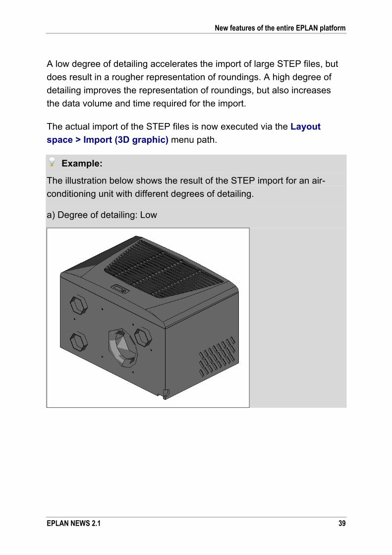
A low degree of detailing accelerates the import of large STEP files, but
does result in a rougher representation of roundings. A high degree of
detailing improves the representation of roundings, but also increases
the data volume and time required for the import.
The actual import of the STEP files is now executed via the Layout
space > Import (3D graphic) menu path.
Example:
The illustration below shows the result of the STEP import for an air-
conditioning unit with different degrees of detailing.
a) Degree of detailing: Low
New features of the entire EPLAN platform
40 EPLAN NEWS 2.1
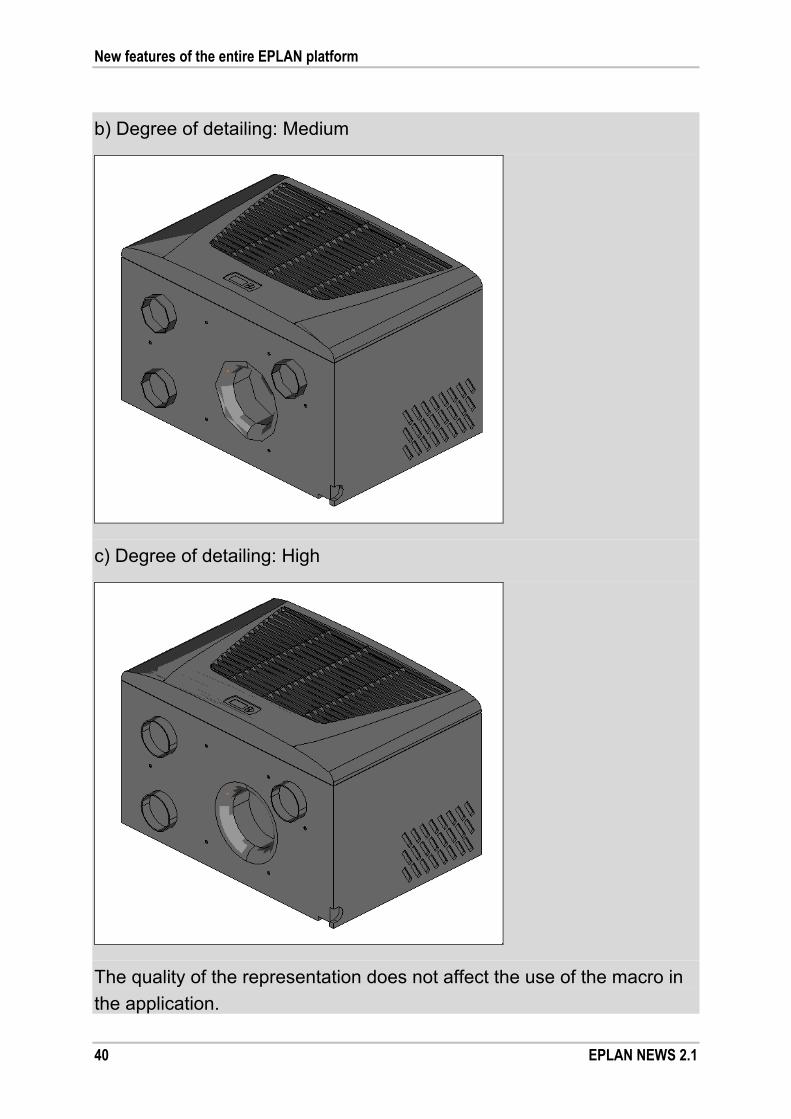
b) Degree of detailing: Medium
c) Degree of detailing: High
The quality of the representation does not affect the use of the macro in
the application.

New features of the entire EPLAN platform
EPLAN NEWS 2.1 41
Rotate 3D view when changing viewpoints
The animated modification of the line of sight allows for more transpa-
rency and better orientation. When changing the 3D viewpoint, the 3D
model represented in the 3D view is now animated and rotated to the
new view in a visually plausible manner. This way, even beginners can
better track the change in the line of sight.
If such behavior is not desired, disable the new Rotate when changing
the viewpoints setting. You will find the relevant check box in the Set-
tings: 3D dialog (under Options > Settings > User > Graphical editing
> 3D). If this is the case, the 3D viewpoint will be changed without anima-
tion.
Display mounting aids
Previously, the mounting points were visible only during the placement of
other items. In the new version, you can now control the visibility of the
so-called mounting aids (handles, mounting points, etc.).
To do so, use in the View menu the new Mounting aids menu item.
Once you have selected this menu item, the mounting aids will be dis-
played in the 3D view of the open layout space, where you can select
and edit them.
New toolbar for the device logic
To create and edit the device logic, you can now use a new toolbar.
Using the Pro Panel device logic toolbar, you can define mounting sur-
faces, handles, mounting points as well as define and modify placement
areas.
The new icons for these functions will also be displayed for the respec-
tive menu items under Edit > Device logic.

New features of the entire EPLAN platform
42 EPLAN NEWS 2.1
Display and modify field size of mounting surfaces
The field size is the physical extension of the item (e.g., a door) that is
inserted in the NC machine (with all mounting). It thus defines the size of
an NC-relevant area from a production perspective. In this context, it is
relevant to the determination of the processing origin whether, for exam-
ple, the door is placed in the drilling robot with or without hinges. From
the field size, therefore, the machine learns the actual extension of the
item that is being processed.
In the case of mounting panels, enclosures and free mounting panels
from EPLAN parts management, the field size is preset automatically.
As a rule, it corresponds to the surrounding rectangle of the entire item,
including all mounting.
In the new version of the "EPLAN Pro Panel" add-on, you can display the
field size of a mounting surface and also easily modify it if necessary. To
do so, use the new Field size menu item in the popup menu of the
layout space navigator.
After you select the popup menu item, two vertical and two horizontal
lines will appear that delimit the field size. You can select one of the lines
with a click of the mouse.
Subsequently, it hangs on the cursor and can be moved in a parallel
fashion using the mouse or the arrow keys. With another mouse click or
the [Space] key, the action is terminated and the field size of this mount-
ing surface is thus redefined.
New features of the entire EPLAN platform
EPLAN NEWS 2.1 43
Generate mounting surfaces
Another innovation is found in the popup menu of the layout space navi-
gator: the new Generate mounting surface menu item. Using this menu
item, you can generate mounting surfaces automatically for a part place-
ment or for an object imported as 3D data that does not yet have any
mounting surfaces. In the process, mounting surfaces are generated that
are appropriate for the set function definition of the items.
Benefit: By allocating a suitable function definition, you can quickly
generate mounting surfaces for a part placement via the
Generate mounting surface popup menu item. This greatly
facilitates the maintenance of master data.
The popup menu item is enabled only if the item selected in the navi-
gator does not yet have a mounting surface and if it has one of the
following function definitions from the areas "Enclosure systems" and
"System accessories":
Body, general
Mounting panel, general
Door, general
Panel, general
Partition, general
Floor sheet, general
Flange plate.
After the selection of the Generate mounting surface popup menu item,
the mounting surfaces planned for the respective function definition are
generated automatically, assigned to the items, and displayed in the
layout space navigator.

New features of the entire EPLAN platform
44 EPLAN NEWS 2.1
Note:
During the import of STEP files, such function definition is assigned auto-
matically as has been preset in the Settings: 3D import dialog. The
function definition of a 3D part placement, however, can also be modified
subsequently. To do so, in the property dialog on the Part placement
tab for the Function definition field, click [...] and select in the subse-
quent dialog the desired function definition.
Model views with simplified representation
The model views in EPLAN Pro Panel can now be displayed with simpli-
fied representation.
Benefit: The simplified representation results in significantly fewer lines
that are represented in the model view. Among other things,
this means that the model view can be updated more quickly,
while also producing more transparency in the representation
and printout, because irrelevant details are left out. The model
view labeling, for example of a terminal strip, is also repre-
sented as simplified.
For this purpose, the Style field on the View tab has been extended to
include the following options:
Hidden lines / Simplified representation: The selected items will
be displayed, independent of the setting made in the related layout
space, with hidden lines and in simplified representation for terminal
strips and 3D macros.
Shading / Simplified representation: The selected items will be dis-
played, independent of the setting made in the related layout space,
with shading and in simplified representation for terminal strips and
3D macros.

New features of the entire EPLAN platform
EPLAN NEWS 2.1 45
As a result, you can now select your own representation for a model
view, regardless of whether a simplified representation has been se-
lected for the related model in the 3D view or not. For example, you
can select the "Shading" style for a model view, while a simplified repre-
sentation has been set in the relevant 3D view. The selected style will be
preserved even after the model view has been updated.
STEP export as a new extension
Using the Layout space > Export > STEP menu items, you can output
graphical data in the STEP format. The exported data can thus be im-
ported into external CAD programs and be visualized there.
For this export, you must also additionally license the "EPLAN STEP
Export" extension (also see section "Modularization of EPLAN Pro Panel
Professional" on page 127).
Notes:
In the STEP export, only faceted 3D data of the EPLAN Pro Panel
model is transferred. Information on analytic curves, surfaces or
volumes is not output.
The "EPLAN STEP Export" add-on is available as an extended
license for EPLAN Pro Panel and EPLAN Pro Panel Professional
as an optional extra. Benefit: Based on the exported data, the mechanical design and / or
fluid power design can add to your 3D composition of a ma-
chine or plant a 3D representation of the expanded enclosure.

New features of the entire EPLAN platform
46 EPLAN NEWS 2.1
Devices
Move positions of parts entered on the device
In the property dialog of devices, you now have the option of moving the
positions of the parts entered on the device. The positions of parts affect,
for example, the sequence in which the parts are output in reports.
Benefit: Using the arrow buttons, you can quickly and conveniently
define the positions of the parts in the property dialog and,
thus, define the required sequence with minimum effort. The
layout of the part assemblies, too, can be controlled directly
from the schematic quite easily.
For this purpose, the Parts tab above the table containing the part
numbers has been extended to include the familiar arrow buttons.
Using the arrow buttons of the toolbars, you can modify the row position
of one or several selected parts. Note that parts can be moved only to
free rows. It is always the complete part with all part reference data that
is moved. The buttons are only active if it is possible to move the se-
lected parts.

New features of the entire EPLAN platform
EPLAN NEWS 2.1 47
Button Meaning
(Move to the
beginning)
Moves the selected part to the first free top position.
(Move up) Moves the selected part up to the position of the
next empty row.
(Move down) Moves the selected part down to the position of the
next empty row.
(Exchange) Swaps the positions of two selected parts.
Graphical editor
Define output size for PDF export
So far project pages, in case of a PDF export, have been output in the
paper format stored in the plot frame in use. In the new EPLAN version,
you can now also modify the output size of the project pages in the
exported PDF file. Consequently, the output pages can be scaled, for
example, directly to DIN A4.
Benefit: In the PDF export, the project pages can be scaled directly to
how they will be printed out later on. Depending on the re-
quirements, you are flexible in your settings for the PDF export
as to whether the size defined by the plot frame is to be output
or whether the pages are to be scaled to a fixed selected size.
This way, you can scale and output different page sizes in one
PDF document to a uniform size.
To define the output size for the PDF export, in the PDF export dialog
click the Settings button and select the new Output size menu item
here.

New features of the entire EPLAN platform
48 EPLAN NEWS 2.1
In the open Settings: PDF output size dialog, you can choose from the
following two options:
Original size:
This is the default setting. If this option has been selected, the project
pages are output in the paper format that has been set via the plot
frame in use.
Scale to page:
If this option has been selected, the project pages are scaled to the
selected paper format and output to the PDF file. The page aspect
ratios are retained during scaling.
In this case, the fields Width and Height are validated. Here you can
enter the paper format dimensions manually. Or, using the [...] button,
which is located next to the Width field, you navigate to a subsequent
dialog and select a paper format from there.
Whether the dimensions are displayed in mm or inches depends on
the displayed unit of length set in the user settings.
New features of the entire EPLAN platform
EPLAN NEWS 2.1 49
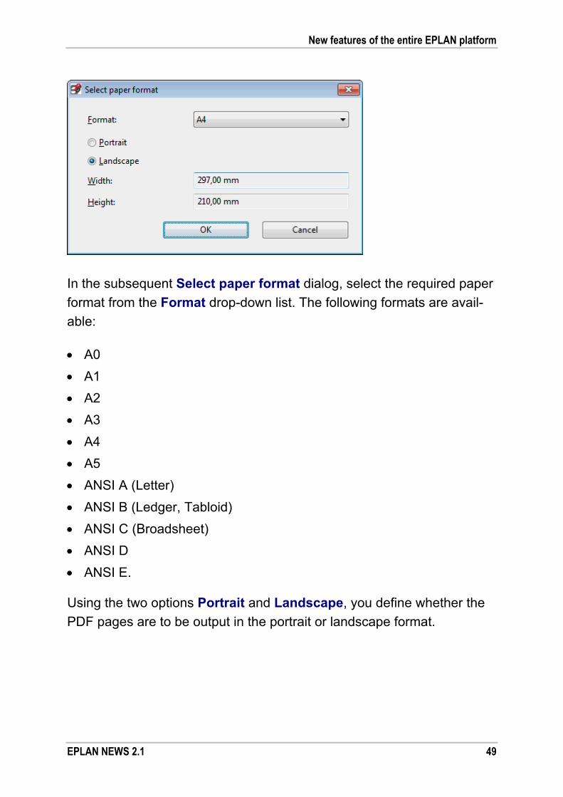
In the subsequent Select paper format dialog, select the required paper
format from the Format drop-down list. The following formats are avail-
able:
A0
A1
A2
A3
A4
A5
ANSI A (Letter)
ANSI B (Ledger, Tabloid)
ANSI C (Broadsheet)
ANSI D
ANSI E.
Using the two options Portrait and Landscape, you define whether the
PDF pages are to be output in the portrait or landscape format.

New features of the entire EPLAN platform
50 EPLAN NEWS 2.1
Note:
Note that the project pages are not rotated in connection with PDF out-put. For example, if you have selected for the output size the DIN A4
portrait paper format, but the project page has the DIN A4 landscape
paper format, the project page will be scaled to DIN A5 and output on
the PDF page.
The dimensions of the selected paper format in the set displayed unit of
length are displayed in the Width and Height fields. The dimensions are
carried over to the Settings: PDF output size dialog.
Display messages about connections in the graphical editor
The Message text (ID 20185) property is now also a property of con-
nections and can be displayed on a connection definition point.
Benefit: With the direct display of messages, you gain an overview of
the message status in the project more easily and more quick-
ly. Directly at the connection, you will see a note, thus enabling
you to remove the cause of the message in a targeted man-
ner.
If the properties of a connection are defined by a connection definition
point, then this innovation will allow you to display messages about this
connection in the graphical editor.
In the property dialog of the respective connection definition point, switch
to the Display tab. For the property arrangement of the components,
click (New) to open the Property selection dialog. Here, select from
the Connection tab the Message text property. Subsequently, following
a corresponding check run, the message texts will be displayed in the
graphical editor that have been output for this connection.

New features of the entire EPLAN platform
EPLAN NEWS 2.1 51
Display of unplaced connections on the component
Connection points of components to which an unplaced connection is
connected are marked in the graphical editor with a small, red, diagonal
line.
In the new version, the display of unplaced connections is enabled to-
gether with the display of connection point directions (via the View >
Connection point direction).
Example:
In this example, the 1 connection point of the -F1 fuse is connected to an
unplaced function. The unplaced connection on the 1 connection point is
indicated by a small, red, diagonal line.
Reports
Simplified selection of the source project when generating a report to another project
The version 2.0 SP 1 offers a new solution for generating reports to other
projects. The reporting of data from a schematic project (known as a
"source project") can take place in a project that is currently open, known
as the "report project". You specify the source project from which the
data originates in the templates for the report project.
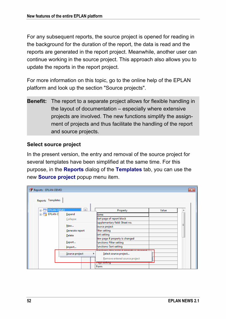
New features of the entire EPLAN platform
52 EPLAN NEWS 2.1
For any subsequent reports, the source project is opened for reading in
the background for the duration of the report, the data is read and the
reports are generated in the report project. Meanwhile, another user can
continue working in the source project. This approach also allows you to
update the reports in the report project.
For more information on this topic, go to the online help of the EPLAN
platform and look up the section "Source projects".
Benefit: The report to a separate project allows for flexible handling in
the layout of documentation – especially where extensive
projects are involved. The new functions simplify the assign-
ment of projects and thus facilitate the handling of the report
and source projects.
Select source project
In the present version, the entry and removal of the source project for
several templates have been simplified at the same time. For this
purpose, in the Reports dialog of the Templates tab, you can use the
new Source project popup menu item.

New features of the entire EPLAN platform
EPLAN NEWS 2.1 53
To enter the source project for existing templates of a report project,
select in the tree of the Templates tab a specific tree structure level
(a project name, report type such as parts list, etc.). Then, select from
the popup menu the Source project > Select source project menu
items, and then the desired source project in the open selection dialog.
For all templates below the selection in the tree, the selected source pro-
ject is entered. For example, if you have selected a project name at the
top tree structure level, the same source project will be entered for all
templates of this project.
Remove entered source project
In the same way, you can again remove the source project for several
templates simultaneously by selecting them in the tree of the Templates
tab and selecting the Source project > Remove entered source pro-
ject popup menu items.
List only used project symbols in symbol overview
In EPLAN, you can now generate a symbol overview that outputs only
the symbols actually used in the project.
Benefit: Using the new Output only used symbols form property, you
can obtain a more compact overview for your projects of all the
symbols used in the project. Thus, you create, at the push of a
button, a frequently requested report to complete your project
documentation.
To do this, you can use a new symbol overview property in the form
properties of the corresponding forms: Output only used symbols
(ID 13114). First select this property in Property selection, then select
the relevant check box in the Value column.

New features of the entire EPLAN platform
54 EPLAN NEWS 2.1
Once you have synchronized the master data of your current project, you
can output a more transparent symbol overview as a report.
Tip:
In the master data of this version, we supply a form (F25_004.f25)
where the Output only used symbols property is already enabled.
Start a consecutive number again at "1"
The Consecutive number (ID 13063) property can be used in list-style
reports (Parts list, Summarized parts list, Terminal-strip overview, etc.) to
number rows consecutively. In this case, every report block (e.g., a ter-
minal strip) is numbered separately.

New features of the entire EPLAN platform
EPLAN NEWS 2.1 55
In the new version, you can now access the two properties Consecutive
number (header) (ID 13092) and Consecutive number (page) (ID
13093). When you use these properties, the row numbers, contingent
on a specific event, are returned to "1".
Start at "1" with each new page
If you set the Consecutive number (page) property, the row number will
start again at "1" on each new page – within a report block. The event for
which a new page is to be created can be controlled during the genera-
tion of reports by using the New page if property value has changed
property.
Start at "1" with each new header
If you use the Consecutive number (header) property, the row number
within a report block will start again at "1" if the header changes. Using
the two form properties Regenerate header after change and / or
Generate data headers for the first x sorting properties, you can
specify the time when a new header is generated on a report page.
All three properties for the "Consecutive number" are available to you for
the "Record" placeholder element in the reports.
Example:
You output a summarized parts list sorted by manufacturer. If in the
Filter / sorting dialog, you use the "Manufacturer" scheme for the New
page if property value has changed field, a new page will be gener-
ated if the manufacturer is changed. The Consecutive number (page)
property inserted in the form as a placeholder text ensures that the row
number starts again at "1" on each new page output.

New features of the entire EPLAN platform
56 EPLAN NEWS 2.1
Placeholder objects
Simplified transfer of variables from properties
In connection with placeholder objects, to help you with the transfer of
variables that have been entered in the properties of the assigned sche-
matic objects, we have extended the Properties (components): Place-
holder object dialog. In the Assignment tab, you can now use the new
Adopt variables popup menu item.
Benefit: The Adopt variables function allows you to transfer quickly
within placeholder objects predefined variables from the pro-
perties of the assigned schematic objects.
Using this function, you can copy valid variable names (e.g., <Variable>) from the Current value column and transfer them to the
Variable column. To transfer a variable, the corresponding row / column
/ cell containing the variable must be selected first. A variable already
entered in the Variable column is not overwritten as part of this action.
Tip:
With this working method, it is recommended that you activate the Only
display properties with value in Current value column check box.
Then, the table of the Assignment tab will only display the properties
where the Current value column has an entry. To transfer all the va-
riables defined in the properties, select the Current value column and
then select the Adopt variables popup menu item. This will transfer the
variable names alone to the Variable column.

New features of the entire EPLAN platform
EPLAN NEWS 2.1 57
Device selection
Easier selection from the accessory list
In order to select an accessory part from an accessory list during device
selection, in the Accessories list click the respective cell of the Selec-
tion column. The subsequently open Select accessories dialog displays
not only the part numbers, but also additional information (e.g., Type
number, Order number, etc.) to facilitate your selection. This selection
dialog displays the same columns that were defined in the column con-
figuration of the Main part list.
Block properties
New format element for device groups
As concerns block properties, the Format dialog now comes with the
new "Device group (further functions)" format element. Using this format
element, within one device group you can access the properties of the
other functions from a function of a device group. Accordingly, for exam-
ple, you can display the part data or the properties of the main function
on a function of the device group, while the main function is placed on a
different page.
Benefit: Block properties generally allow you to display properties in a
flexible and automatic manner and, thus, to define the informa-
tion content of the documentation individually. Especially when
it comes to device groups, the new functions open up new
possibilities. The redundant-free data management guaran-
tees a high level of quality and at the same time reduces the
expenditure related to data maintenance.

New features of the entire EPLAN platform
58 EPLAN NEWS 2.1
Example:
In the sample project EPLAN-DEMO, we have placed on the page
=FB3+FT2/1 (with the page description Pneumatics Clamping
fixture) a valve device group as a black box with the displayed DT
1-1V1. The part was stored on the black box, the main function. The
device group includes two valves (solenoids), for which the "Pair cross-
reference" representation type has been set. In order to be able to dis-
play at the counterpieces of the valves on the electrical engineering
schematic page the part data of the main function, first jump to the cor-responding page =EB3+ET2/3. To do so, click one of the valves with pair
cross-reference and then select the Go to (counterpiece) popup menu
item.
At the valve (e.g., -Y1), use property selection to add the Block prop-
erty: Format [1] property to the property table. Use the [...] button in the
Value column to display the Format dialog. In the Available format
elements field, under "Device group (further functions)", select the entry
"Function properties 1". Click the (Next level) button. This way, you
can go to the further functions of the device group and select the desired
property there.
In the Available format elements field, expand the "Parts data" format
element. Below the "Parts data General" group, select, for example, the
entry "Parts data 1", and click (Move to the right). In the Format:
Block properties dialog, select, for example, the Part number property.
After you have closed the Format dialog and the property dialog, the part number of the valve device group MEBH-5/3G-1/8-B-110AC will be dis-
played as property text in the schematic. If so desired, repeat this for the
second valve.

New features of the entire EPLAN platform
EPLAN NEWS 2.1 59
New features in the "EPLAN Revision Management" add-on
Note:
The "EPLAN Revision Management" add-on is available for EPLAN Elec-
tric P8 Select as an optional extra. For EPLAN Electric P8 Professional
and EPLAN Fluid, this add-on is now part of the default scope.
Revision control, the "EPLAN Revision Management" add-on, is used to
automatically record and document subsequent modifications to existing
plants.
Property comparison of connection definition points
In property comparisons of projects in revision control, connection defi-
nition points used to be included in the "devices". This captured changes
to the displayed DT, but not to connection-specific properties (e.g., Con-
nection designation, Connection color / number, etc.).
With the new version, you can now compare all the properties of the con-
nection definition points when running a property comparison. This takes
into account connections and connection definition points jointly in the
comparison.
Benefit: Norm-compliant change tracking and revision are of growing
importance due to requirements contained in norms and
guidelines. All the more important is the automatic support of
the user by the EPLAN platform. Save time and increase the
quality of your projects by using the EPLAN revision control
and by documenting modifications continuously and transpa-
rently over the course of the project.
New features of the entire EPLAN platform
60 EPLAN NEWS 2.1
For this reason, the Settings: Property comparison of projects dialog
provides for the "Connections" category further property groups (e.g.,
General, Formats, etc.) in the Do not compare field. If you move the
desired connection-specific properties to the Compare field, the changes
to these properties will be captured as well in the property comparison of
projects.
New features in the "EPLAN Project Options" add-on
Note:
The "EPLAN Project Options" add-on is available for EPLAN Electric P8
Professional, EPLAN Fluid, and EPLAN PPE as an optional extra.
This add-on allows you to define areas of a machine or plant as project
options and then reveal or hide them within the EPLAN project. This way,
configuration characteristics or a different dimensioning of a machine or
plant can be easily represented and managed by means of project op-
tions. Hidden project options are then also no longer evaluated.
Modify sections subsequently
For this version, the project options navigator of the "EPLAN Project
Options" add-on has been extended. Using the new Assign objects to
the section popup menu item, you can now modify specific project op-
tion segments subsequently. In this context, it is possible to add further
objects to the section or to replace the content entirely with new objects.
Benefit: Modifications to individual machine and plant options or
variants can now be tracked quickly and easily using the
"Maximum project". This will make the use of project options
even more flexible. This is a key advantage when it comes
to being able to respond, on short notice but still in a quality-
assured manner, to changed requirements in the project.

New features of the entire EPLAN platform
EPLAN NEWS 2.1 61
First, select the objects you want to add to the section or that you want to
use to replace the content of the section. These may include, for exam-
ple, a schematic section in the graphical editor, objects in a layout space,
functions in one of the project data navigators or pages in the page navi-
gator.
In the Project options - <Project name> dialog, select the section that
you wish to modify. Select the Assign objects to the section popup
menu item. If the selection contains objects that can be assigned to the
section, a prompt will be displayed asking whether objects not selected
should be removed from the section.
If you confirm the prompt with [Yes], the previous content of the sec-
tion will be deleted and replaced by the selected objects.
If you confirm the prompt with [No], the previous content of the sec-
tion will not be deleted, and the selected objects will be added to the
section.
Note:
A section containing pages can be assigned only further pages (but not
functions). A section containing functions can be assigned only further
functions (but not pages). If you have selected objects that cannot be
assigned to the section, you will be shown a message, and the action
will be aborted.
Tip:
If a section has been selected in the Project options - <Project name>
navigator dialog, the content of the section will be displayed in the graph-
ical preview. If multiple sections have been selected, they will be shown
below and next to each other in the preview.

New features of the entire EPLAN platform
62 EPLAN NEWS 2.1
New features in the "EPLAN User Rights Management" add-on
Note:
The "EPLAN User Rights Management" add-on is available as an option
for EPLAN Electric P8 Select, EPLAN Electric P8 Professional, EPLAN
Fluid, and EPLAN PPE.
With the "EPLAN User Rights Management" add-on, an administrator
can configure both the user rights and the user interface (dialogs, menu
structure, etc.) of the EPLAN platform.
Update the rights management
Numerous rights for rights management have been added in the new
EPLAN version. At the time of an initial installation, the predefined user
groups (administrators, guests, etc.) have already been assigned the
new rights.
Benefit: Especially when a larger group of designers is involved,
EPLAN rights management can support and implement a
precise definition of tasks and responsibilities. Give each user
the program functions necessary for his or her area of tasks.
Functions not released for a user are hidden in the menus.
As a result, the user is supported optimally by way of a trans-
parent program version tailored to his or her task.
When switching from an older EPLAN version to version 2.1, you must
update the rights management. You can tell, for example, by the fact
that in the Rights field there are new topic areas not yet assigned (oper-
ational sequence sheets, manufacturing interfaces) even for the group of
administrators.
New features of the entire EPLAN platform
EPLAN NEWS 2.1 63
In addition, some existing topic areas have been extended to include
new rights. This is why the rights in these topic areas are assigned only
partially even for administrators prior to the update. This involves the
following topic areas:
Graphical editor / Navigator
Interfaces
Layout space
Macro technique
Options / Placeholder objects
Outline editor
PLC
Project management
Settings: Company
Settings: Projects
Settings: User.
To update, in the Rights management dialog, click the [Update] button.
After updating, the System messages dialog is automatically opened.
Here you can see which rights have been added or removed.
The new rights are then available for the existing user groups. By default,
they are activated for all groups, including "Guests".

New features of the entire EPLAN platform
64 EPLAN NEWS 2.1
New interface to link to Autodesk Vault
Aside from the Autodesk Productstream Professional interface, the
EPLAN platform now also comes with an interface to link to Autodesk
Vault. This bidirectional EPLAN interface is used to manage design data
from AutoCAD Inventor or Mechanical together with electrical engineer-
ing and fluid power projects. Such an interface linking to one of the
Product Data Management solutions (PDM) of Autodesk can be installed
on the EPLAN platform as an add-on.
Benefit: By coupling the EPLAN platform to the product management,
the machine and plant documentation of the automatization
technology is integrated with the entire engineering-PDM
process seamlessly. Thus, the status of all documents is
transparent for all project members at any time, and can still
be tracked even after project work has been completed.
Through the integration, EPLAN is also integrated with all
workflows and release processes defined via the PDM.
User interface
New shared menu item for data import
The menu items for importing data from projects and data from previous
EPLAN products have been moved from the Project menu to the Utili-
ties menu. The data import is now called via the shared Data transfer
submenu item.
Example:
The dialogs for the EPLAN 5 data import are now opened via the
Utilities > Data import > EPLAN 5 / fluidPLAN menu path.

New features of the entire EPLAN platform
EPLAN NEWS 2.1 65
Property preview removed
The Property preview dialog, which you were previously able to open in
EPLAN via the View > Property preview menu path, has been removed
from the new version.
Navigator dialog for device properties removed
The dockable navigator dialog for the properties of a device has been re-
moved from this version. The related Project data > Devices > Proper-
ties menu path has also been removed from the EPLAN platform.
The device navigator and the property dialogs for devices, of course, are
still available to you in the EPLAN platform.
Divide projects into defined working sections
66 EPLAN NEWS 2.1
Divide projects into defined working sections
Note:
The "EPLAN Multiuser Management" add-on is available for EPLAN
Electric P8 Select, EPLAN Electric P8 Professional, and EPLAN Fluid
as an optional extra.
Projects with several users are frequently very extensive projects. Even
though a single user works on only one part of the project, the program
must still consider, update and synchronize all the project data. Large
projects also often lack the necessary transparency for the individual
user.
To keep the data volume transparent and compact for a single user in
such an application case, while reducing data management by means of
the EPLAN platform, we now give you the new "EPLAN Multiuser Man-
agement" add-on. You can use this function to divide projects structured
by identifier blocks into so-called "defined working sections".
Benefit: By dividing a project into individual workspaces, each editor
can focus on his or her area of responsibility. At the same
time, the EPLAN platform helps ensure that all global pro-
ject information is synchronized continuously and that help-
ful navigation functions can be used. This makes even
extensive projects more transparent, facilitates the orien-
tation, and consequently produces improved quality in the
planning process. Since EPLAN in this configuration has
to manage less data per user, the response speed of the
program is increased.
If the individual users work only in specific sections when
in multi-user operation, the clearly defined responsibilities
reduce multi-user conflict. There is less need for coordina-
tion, and project editing is accelerated.
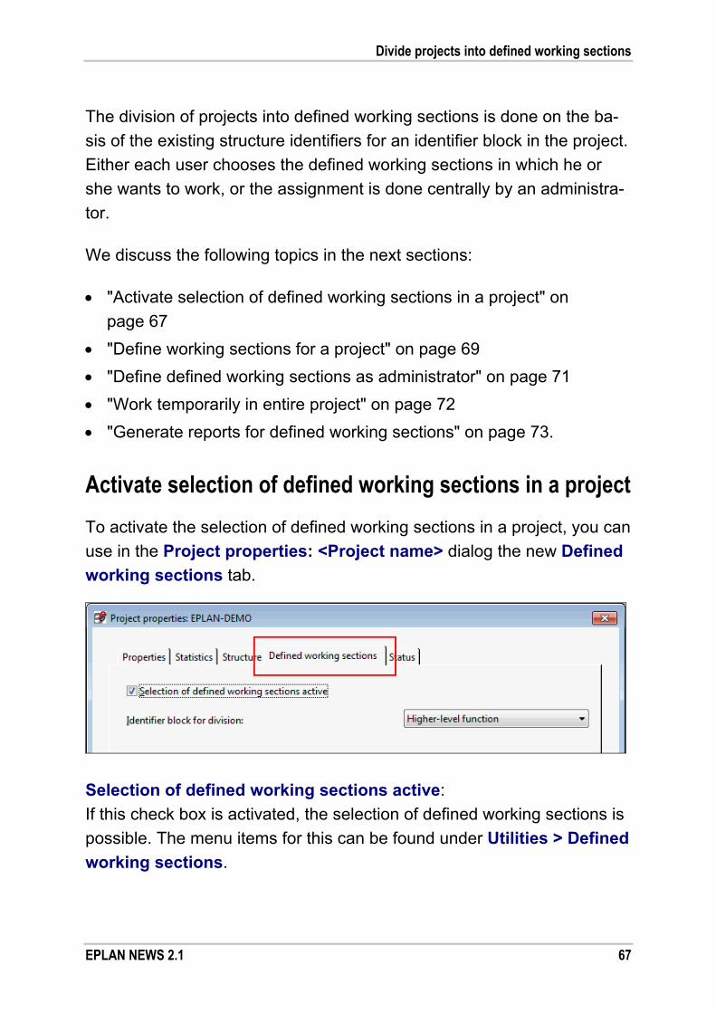
Divide projects into defined working sections
EPLAN NEWS 2.1 67
The division of projects into defined working sections is done on the ba-
sis of the existing structure identifiers for an identifier block in the project.
Either each user chooses the defined working sections in which he or
she wants to work, or the assignment is done centrally by an administra-
tor.
We discuss the following topics in the next sections:
"Activate selection of defined working sections in a project" on
page 67
"Define working sections for a project" on page 69
"Define defined working sections as administrator" on page 71
"Work temporarily in entire project" on page 72
"Generate reports for defined working sections" on page 73.
Activate selection of defined working sections in a project
To activate the selection of defined working sections in a project, you can
use in the Project properties: <Project name> dialog the new Defined
working sections tab.
Selection of defined working sections active:
If this check box is activated, the selection of defined working sections is
possible. The menu items for this can be found under Utilities > Defined
working sections.
Divide projects into defined working sections
68 EPLAN NEWS 2.1
If the check box is deactivated, the selection of defined working sections
is disabled, and you edit the entire project.
Note:
Sequentially numbered projects cannot be divided into defined working
sections. Identifier block for division:
The drop-down list shows all identifier blocks that have been defined in the project structure as being identifying. In the example project EPLAN-
DEMO, these are, for example, the identifier blocks "Higher-level function",
"Higher-level function number", and "Mounting location".
Here, select the identifier block that is to be used for the division of the
current project. Each structure identifier of the selected identifier block
defined in the project defines a working section.
Example:
For the example project EPLAN-DEMO, the identifier blocks "Higher-level
function", "Higher-level function number", and "Mounting location" have
been defined as identifying in the project properties on the Structure tab.
These identifier blocks are offered to you for selection in the Defined
working sections tab in the Identifier block for division field.
In this drop-down list, if you select the "Higher-level function" identifier
block for dividing the project into defined working sections, the Define
working sections dialog will show you the structure identifiers "CA1",
"EB3", "FB3", and "REPORT" as defined working sections.

Divide projects into defined working sections
EPLAN NEWS 2.1 69
Define working sections for a project
If you have activated the selection of defined working sections for a pro-
ject in the project properties, you will be able to use the functions to de-
fine the working sections. The corresponding menu items will then be
validated under Utilities > Defined working sections.
To set the defined working sections within a project, select the Utilities >
Defined working sections > Define menu items. Alternatively, in the
Default toolbar, you can also click the new icon (Define working sec-
tions).
In the then-open dialog Define working sections, the structure identifi-
ers of the identifier block are displayed that was selected for the division
into defined working sections.
In the Definition table, you set your defined working sections by activat-
ing the check boxes for the required structure identifiers in the My de-
fined working sections column. In the All editors column, you will also
see the other editors who have selected a defined working section in the
project.

Divide projects into defined working sections
70 EPLAN NEWS 2.1
After closing the dialog with [OK], you will see in the project data naviga-
tors only the pages, devices, etc. with the corresponding structure iden-
tifiers.
If the selection of defined working sections has been activated for a
project, a percentage symbol "%" is displayed in front of the project
name in the title bar of the navigators (e.g., in the page navigator:
Pages - %EPLAN-DEMO).
Notes:
Devices, terminal strips, etc. that have not been sorted into a defined
project structure by means of structure identifiers are part of the de-
fined working section "Empty identifier". This defined working section
can also be selected for editing.
If a user enters a new structure identifier during project editing, it will
be displayed immediately in the Define working sections dialog, but
the creator of this structure identifier is not automatically entered for
the editing of the section.
Tip:
Using the Go to (graphic) popup menu item, you can jump to an object
(page / layout space) that does not belong to your defined working sec-
tion. This way you can, for example, jump from a report page to the
associated schematic page and make modifications there, even if the
schematic page is not part of your defined working section.
Open projects with active selection of defined working sections
If the selection of defined working sections has been activated for a
project, when you open this project you will see the Define working
sections dialog immediately.

Divide projects into defined working sections
EPLAN NEWS 2.1 71
If you access a project via a network with several users, the All editors
column will show you whether another user has already defined a work-
ing section for this project. But this will not show you whether another
user has already opened the project.
Display of defined working sections in the multi-user monitor
To allow you to see in the multi-user operation when another user has
selected a defined working section in an opened project, the Multi-user
monitor dialog has been extended (see relevant sections beginning on
page 75).
As a result, the table on the left, Own opened projects in multi-user
operation, now comes with the Area column. This column displays the
structure identifiers that another user has defined in the respective pro-ject as a defined working section (e.g., for the example project EPLAN-
DEMO: CA1; EB3). If another user temporarily works in the entire project,
the Area column will show the entry "No limitations".
Define defined working sections as administrator
When you use the rights management of EPLAN, the defined working
sections can be assigned centrally by an administrator.
Note:
The user names used for the assignment of defined working sections
must have been created previously under rights management.
In order to assign the defined working sections of a project to different
editors as an administrator, select the Utilities > Defined working sec-
tions > Define as administrator menu items.

Divide projects into defined working sections
72 EPLAN NEWS 2.1
In the then-opened Define working sections as administrator dialog,
the All editors column is validated. There, you can enter new editors for
the respective defined working section or delete them. Several editors
are separated by a comma.
Tip:
In the All editors column, you can carry the content of a cell over to
other cells using Copy and Paste.
Select editor
You can also display the users defined in rights management, and select
one or several of them. To do so, in the row of the required defined work-
ing section, click the All editors table cell, followed by the [...] button.
In the subsequent Select editor dialog, activate the check boxes in the
Assign column for the editors that are to be assigned the respective de-
fined working section. Or deactivate the check boxes for the editors that
are to be removed from the defined working section. Using the User
group drop-down list, you can filter the editors according to the respec-
tive user group (administrators, guests, schematic editors, etc.).
After you have closed the subsequent dialog with [OK], the selected edi-
tors will be displayed in the Define working sections dialog in the All
editors column.
Work temporarily in entire project
The EPLAN platform contains editing actions (e.g., the numbering of
devices) that you do not execute only for the current selection, but that
you can also extend to the entire project. The dialogs allowing this con-
tain the Apply to entire project check box.
Divide projects into defined working sections
EPLAN NEWS 2.1 73
When you work in a project with defined working sections, such editing
actions, despite an active setting, will not affect the entire project, but
only your defined working section.
If you still want to execute the editing for the entire project, you will have
to extend your defined working section temporarily to the entire project.
Select the Utilities > Defined working sections > Entire project menu
items. Alternatively, in the Default toolbar, you can also click the new
icon (Edit entire project). Subsequently, the entire project is displayed
again in the project data navigators.
After you have completed the action, exit the temporary editing in the
entire project and select the menu item again.
Update connections
A manually executed or automatic connection update only affects the
current defined working section. In this context, a connection belongs to
a defined working section as soon as a target of such a connection be-
longs to the defined working section.
Note:
Please note that non-current connections can result in incomplete re-
ports (for example, in case of connection diagrams). To update a con-
nection for the entire project, you must first extend your defined working
section temporarily to the entire project.
Generate reports for defined working sections
To generate reports on defined working sections, go to Utilities > Re-
ports and select the Generate project reports menu item. This menu
item allows you to evaluate all reports that are part, fully or partially, of
your defined working section.

Divide projects into defined working sections
74 EPLAN NEWS 2.1
Any report pages outside of your defined working section cannot be
deleted, created, or updated. This also applies to the model views.
To generate a report of the entire project, you must first extend your
defined working section temporarily to the entire project.
We recommend that you output the reports of your defined working sec-
tion in a separate report project. The reports of the entire project can be
output either in another report project or be contained in the project itself,
and, for example, they can be generated and updated overnight. For
more information on this topic, go to the online help and look up the
section "Source projects".

New monitor for multi-user mode
EPLAN NEWS 2.1 75
New monitor for multi-user mode
Note:
The "EPLAN Multiuser Monitor" add-on is available as an option for all
module packages for the program variants EPLAN Electric P8, EPLAN
Fluid, EPLAN PPE, EPLAN Education for Classrooms, and EPLAN View.
Version 2.0 SP 1 introduces a new monitor for multi-user operation. This
new add-on will help you to see which other users are active on which
project. You will see at a glance the actions of other users in the project,
thus allowing you to efficiently coordinate the project work.
Benefit: Who has already made a start on which project? Are there
comprehensive reports or checks already running in the cur-
rent project? It is important to have a quick and simple over-
view of the actions of individual people, particularly when
working on projects with multiple users. Structured and effi-
cient configuration shortens project implementation times,
and this is perfectly supported by the multi-user monitor. When
combined with well thought-out organization of the configure-
tion work, the new multi-user monitor will be the central source
of information for transparency in your current projects.
The following sections discuss how to set up and use the multi-user
monitor:
"Set up the multi-user monitor" on page 76
"Define the settings for the multi-user monitor" on page 77
"Use the multi-user monitor" on page 78.

New monitor for multi-user mode
76 EPLAN NEWS 2.1
Set up the multi-user monitor
The monitor for multi-user operation was implemented as a client-server
solution.
The server application is installed on the required computer by the
EPLAN installation wizard. This may also be a "normal" EPLAN work-
station. The server application is then available as a service in the server-computer's Control Panel. This EPLAN Multiuser Monitor
service starts automatically. It can be uninstalled as usual in the Add
or Remove Programs dialog in Control Panel.
For the other EPLAN workstations to be able to log onto this "monitor
server" when the program is started, a further setting has to be made in
EPLAN on the relevant client computers (see the following section on
page 77). When the service and the client-server connection have been
set up, the monitor server receives the information about actions that
have been carried out, collates it, and redistributes it to the EPLAN work-
stations.
Notes:
The server application "EPLAN Multiuser Monitor" must be installed
from a user account with administrator rights. You will need the rele-
vant authorizations to start, exit and restart services.
We recommend that a system administrator sets up the multi-user
monitor and makes the necessary settings on the EPLAN worksta-
tions. You will find the other settings and requirements for multi-user
mode in the "Multi-user Operation" section of the EPLAN online help.

New monitor for multi-user mode
EPLAN NEWS 2.1 77
Define the settings for the multi-user monitor
You will first have to make a few settings before you can display the
multi-user mode data on the multi-user monitor at an EPLAN work-
station. The menu path is as follows: Options > Settings > User >
Management > Multi-user monitor.
In this dialog, specify the computer on which the monitor server service
has been set up. Enter the relevant details in the Server name and Port
boxes. Check the Active check box to establish the connection with the
server.
Click the [Check] button to check the settings: If there is a connection to
the server computer, a suitable message is sent to the Status field.
New monitor for multi-user mode
78 EPLAN NEWS 2.1
Use the multi-user monitor
To open the multi-user monitor, select Project > Multi-user monitor.
The Multi-user monitor dialog is in table format, similar to other familiar
dialogs such as message management. As in that dialog, the multi-user
monitor can be docked and undocked on EPLAN's main window and
saved with a workspace.
This dialog has two tables listing the projects that are relevant for multi-
user operation. If you have not opened a project in multi-user mode, do
not have access to the project directory for multi-user mode or are not
connected to the monitor server, then one or both tables are empty.
Own opened projects in multi-user operation:
The table on the left provides detailed information about the multi-user
operation. It shows the projects that you and other users have open at
the same time. The following data is listed for these projects:
Project
Users
Area
Product version
Project action
Progress.

New monitor for multi-user mode
EPLAN NEWS 2.1 79
If a user has started an action with a corresponding run-time for a project
that you also have open (checks, reports, etc), this will be indicated by a
progress bar in the Progress column.
If, in the User column, you click the User code set up as a hyperlink, the
email application on your computer opens and you can email this user.
If you click the icon to the left of a project name, other information
about a user appears in both tables (name, phone, computer). For this
to happen, the users working in multi-user mode must have saved their
user data in the settings (Options > Settings > User > Display > User
code / address).
Note:
Projects that only you have open do not appear in the multi-user monitor. Other open projects:
The table on the right of the dialog lists all the projects that have only
been opened by other users. The following data is listed for these pro-
jects:
Project
User.
If more than one other user has a project open, the Users column dis-
plays more than one User code for the relevant project.
If you wish to email a user in this table, you first need to drop down the
row of information below. Here, click the user name that has been set up
as a hyperlink.

New monitor for multi-user mode
80 EPLAN NEWS 2.1
Possible steps Get information from the multi-user monitor before the action
In multi-user mode, you want to start a lengthy action for an open project
(e.g. a project-wide check or report, etc.). To do this, first use the monitor
to find out whether another user has also initiated such an action for the
current project.
If this is not the case, start the required action.
If a lengthy action is being carried out for the current project, you have
the following options:
You accept that execution will be lengthy and start your action none-
theless.
You can postpone your action to later.
You can contact the other user to discuss things. To do this you can,
e.g., click the other user's user ID in the User column and send an
email.
Get information from the multi-user monitor during the action
You start an action. Because the action is taking longer than usual to
execute, you open the multi-user monitor. Here you find out whether the
delay is being caused by actions running in parallel in multi-user mode.
If it is, you have the following options:
You accept that execution will be lengthy and wait until your action is
finished.
You stop your action by clicking [Cancel]. You can then – as stated
previously – contact the other user to discuss things.

Performance improvements
EPLAN NEWS 2.1 81
Performance improvements
Through several optimizations and internal modifications, significant per-
formance improvements have been achieved for various areas of the
EPLAN platform.
Improved performance through optimized project database
The many extensions and implemented customer requests resulted in
comprehensive modifications to the project databases in Version 2.1.
By optimizing the project databases, we have achieved, for example,
improved performance in the areas "Multi-user operation", "Filter technol-
ogy", "Display in the navigators", "Connection updating", and "Reports".
Consequences for projects
These modifications and optimizations make it possible to create new
projects essentially with new project databases.
In order for old projects to be edited in the new EPLAN version, updat-
ing of the project databases is absolutely essential for these projects.
Old projects are updated the first time they are opened with the current
EPLAN version. You will see a prompt asking you whether you wish to
update.
Warning:
New projects and old projects that have been updated can be opened
with the EPLAN versions 2.0, 2.0 SP 1 and 2.1. Older EPLAN versions
(prior to version 2.0) cannot open the updated projects anymore!
If you do not update an old project, you will still be able to open this
project in the version 2.1, but you can only view it, and not edit it.

Performance improvements
82 EPLAN NEWS 2.1
Changed program behavior
The program behavior of the EPLAN platform has been modified as
follows to improve performance:
Connections are no longer updated prior to printing (since EPLAN
version 2.0 SP1).
In the graphical editor, when you leaf through the pages of a project,
you will now see at first only the graphical information before the page
is fully loaded. This allows for a faster change of page when "leafing"
through several pages.
When in multi-user operation, opening a project triggers a check of
the project master data in case the master data needs to be synchro-
nized only for the first user. This allows other users to open the project
faster.
When updating report pages, the program now only looks at the prop-
erties that can be modified when updating the report. This prevents
unnecessary data queries, and the report pages are updated faster.
The performance of error checking has also been improved thanks
to an internal modification. To see which program modifications to
message management have improved the performance, see section
"Message management" on page 29.

Special topics EPLAN Electric P8
EPLAN NEWS 2.1 83
Special topics EPLAN Electric P8
Terminals / plugs
Store parts for pins and busbar connection points
You can now store parts for pins in EPLAN. This allows you to enter the
corresponding parts on each male pin and female pin of a plug. You can
now also store parts on busbar connection points.
Benefit: You can now define custom-equipable plugs. You define the
individual detail depth to which the plug is projected. If neces-
sary, store all information you need to also manufacture a free-
ly configurable plug. Following the planning in the schematic,
you can generate extensive reports on the basis of the project
data (e.g., detailed manufacturing documents) at the push of a
button.
For this purpose, the property dialogs of the pins and busbar connection
points have been extended to include the Parts tab. By default, the parts
entered here are captured as pin parts / busbar connection point parts.
The parts entered on the Parts tab can be evaluated in the same way as
the parts of terminals. For this reason, the parts settings for reports,
labeling, and the bill of materials of the bill of materials navigator have
been extended.

Special topics EPLAN Electric P8
84 EPLAN NEWS 2.1
Using the new check boxes Plug parts, Pin parts, Busbar parts, and
Busbar connection point parts, you can define the parts to be record-
ed in the bill of materials or to be output in part reports / labeling.
Note:
For fully configured plugs, you usually enter all parts (both the plug
housing and the pins) on the plug definition. For freely configurable
plugs, you enter only the part for the plug housing on the plug definition.
The parts for the pins are entered at the respective pin.

Special topics EPLAN Electric P8
EPLAN NEWS 2.1 85
Placeholders for pins
The placeholder texts of the plug diagram have been extended for the
display of parts and part reference data of pins. The following new place-
holder elements are now available in the Placeholder texts - Plug
diagram dialog for the respective form:
Female pin end: Pin part
Female pin end: Pin part reference
Pin part
Pin part reference
Male pin end: Pin part
Male pin end: Pin part reference.
The following placeholder elements have also been renamed:
Old name: New name:
Parts data Plug part
Part reference data Plug part reference
Female pin end: Parts Female pin end: Plug part
Female pin end: Part reference Female pin end: Plug part reference
Male pin end: Parts Male pin end: Plug part
Male pin end: Part reference Male pin end: Plug part reference
Improved overview in the "Connections" tab
In the Connections tab of the property dialog for terminals, you can
change certain properties of the terminal connection points and their
connections, such as the potential type or the Cable connection point
property. In the new version, a separate Connection point [n] tab is
displayed for each function connection point of the terminal of the con-
nection point type "Conductor / wire". Function connection points with
other connection point types (e.g., jumper connection points) are not
displayed.

Special topics EPLAN Electric P8
86 EPLAN NEWS 2.1
Benefit: Since for each conductor / wire connection point a separate
tab is displayed, you will gain a better overview of each con-
nection point even with a larger number of targets.
Example:
For a terminal with six connection points (e.g., X4_B_1 symbol), with the
first four being of the "Conductor / wire" connection point type and the
other two being the "Saddle jumper" connection point type, four tabs are
displayed: Connection point 1, Connection point 2, Connection point
3 and Connection point 4.

Special topics EPLAN Electric P8
EPLAN NEWS 2.1 87
New features in the "EPLAN PLC & Bus Extension" add-on
Note:
The "EPLAN PLC & Bus Extension" add-on is available for EPLAN Elec-
tric P8 Select as an optional extra. For EPLAN Electric P8 Professional,
this add-on is now part of the default scope.
The "EPLAN PLC & Bus Extension" add-on helps you to manage PLC
controllers and bus systems.
Benefit: Schematic and PLC configuration data can be exchanged bi-
directionally. The synchronization thus ensured between the
electrical design and the PLC automatization technology in-
creases the quality of the project documentation and reduces
also the synchronization efforts in downstream project phases
(e.g., manufacturing, commissioning, service).
Updated interfaces for exchanging data with PLC configuration systems
In this version, two interfaces for the data exchange with PLC configura-
tion systems have been updated.
Schneider Unity Pro
This interface allows the exchange of PLC data between EPLAN Electric
P8 and the "Unity Pro" PLC configuration software from Schneider
Electric. EPLAN now also supports "Unity Pro" in Version 5.0.
Siemens SIMATIC STEP 7
The interface for "Siemens SIMATIC STEP 7" has also been extended.
EPLAN now also supports Version 5.5.

Special topics EPLAN Electric P8
88 EPLAN NEWS 2.1
Both data exchange dialogs, Export PLC data and Import PLC data,
have been adjusted for the following formats according to the new fea-
tures mentioned above:
Schneider Unity Pro V4.0 / V5.0
Siemens SIMATIC STEP 7 Version 5.4 / 5.5.

Special topics EPLAN Fluid
EPLAN NEWS 2.1 89
Special topics EPLAN Fluid
Rotate and mirror symbols and macros
The rotating and mirroring of graphical elements is a default function of
the EPLAN platform. With the new EPLAN Fluid version, you can now
also rotate and mirror "logical" symbols and macros.
Benefit: By rotating and mirroring symbols and macros, you can create
master data and partial schematics easily and quickly.
Possible applications for fluid power
If while creating master data you wish to create variants of symbol
macros in a macro project, you can do without the tedious drawing of
the symbol graphic and placement of property texts by rotating and
mirroring macros.
Partial schematics are often used in mobile hydraulics; they consist
of several devices. You can create a quick mirrored copy of a partial
schematic by way of mirroring.
Note:
The "Rotate and mirror symbols and macros" function is also available to
you in all other program variants of the EPLAN platform.
Since rotating and mirroring no longer affects only the graphical ele-
ments, the two menu items Rotate and Mirror were removed from the
Edit > Graphic menu and re-inserted in the Edit menu below the Move
menu item.
Rotate and mirror symbols
When rotating and mirroring symbols, there is an internal exchange of
symbol variants. The property arrangement of the placed property texts
(Displayed DT, Cross-references, etc.) is rotated or mirrored as well.

Special topics EPLAN Fluid
90 EPLAN NEWS 2.1
This means that the symbols can be rotated or mirrored only in 90° steps.
To ensure that the result of the rotation or mirroring meets your expecta-
tions, the symbol variants must be set up accordingly in the master data.
When you rotate, the variants A to D are taken into account.
Example:
In the following figure, the A symbol variant of a silencer (254 / F15.3.1
symbol from the PNE1ESS library) is rotated in three 90° steps. In this
example, the coordinate cross is the point around which the rotation is
carried out.
When rotating the A symbol variant by 90°, the B symbol variant is used;
for rotations by 180°, the C symbol variant, and for rotations by 270°, the
D symbol variant.
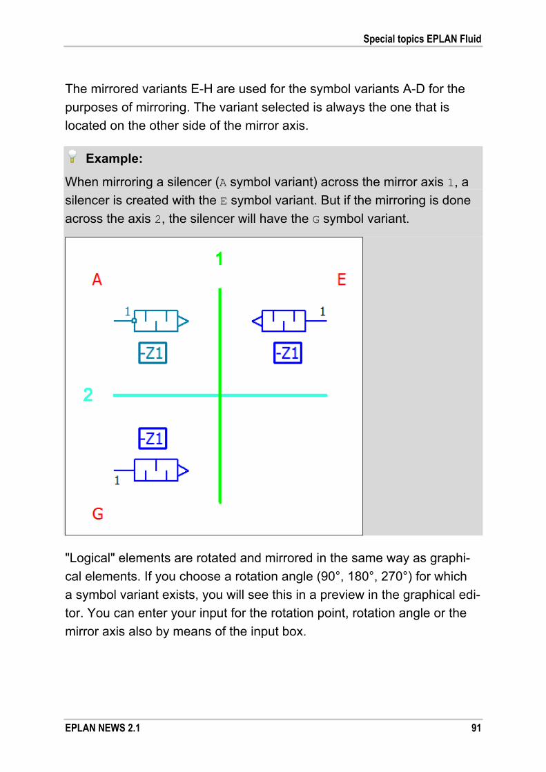
Special topics EPLAN Fluid
EPLAN NEWS 2.1 91
The mirrored variants E-H are used for the symbol variants A-D for the
purposes of mirroring. The variant selected is always the one that is
located on the other side of the mirror axis.
Example:
When mirroring a silencer (A symbol variant) across the mirror axis 1, a
silencer is created with the E symbol variant. But if the mirroring is done
across the axis 2, the silencer will have the G symbol variant.
"Logical" elements are rotated and mirrored in the same way as graphi-
cal elements. If you choose a rotation angle (90°, 180°, 270°) for which
a symbol variant exists, you will see this in a preview in the graphical edi-
tor. You can enter your input for the rotation point, rotation angle or the
mirror axis also by means of the input box.

Special topics EPLAN Fluid
92 EPLAN NEWS 2.1
Tip:
If you press the [Ctrl] key while rotating / mirroring, a copy of the se-
lected "logical" elements (symbols, macros) will be rotated / mirrored and
inserted. The original elements remain unchanged. After the action, you
will see, by default, the familiar Insertion mode dialog. Here, you can
set the online numbering of the devices.
Note:
If graphical and logical elements are rotated or mirrored together, the
graphic, too, will be rotated or mirrored only in 90° steps.
Rotate and mirror macros
Macros (symbol (*.ems) or window macros (*.ema)) are rotated and
mirrored on the basis of macro variants. In the process, all objects within
a macro box are identified internally. In the respective action, the logical
information (e.g., displayed DT, connection point designations, etc.) is
preserved; all graphical information (e.g., position of the symbol graphic
and property texts as well as the symbol variant) is imported from the
respective macro variant.
If a necessary macro variant is not available for the respective macro
box, the objects will be transformed (rotated / mirrored) on the basis of
existing symbols. In such a case (or when other inconsistencies occur),
you will receive relevant information in the system messages.
Note:
If macros are to be rotated and mirrored only on the basis of symbols,
press the [SHIFT] key when executing the respective action. If you use
the shortcut key [Ctrl] + [SHIFT], the action will be executed on the basis
of symbols, while preserving the original macro.

Special topics EPLAN Fluid
EPLAN NEWS 2.1 93
Transformation point for symbol variants
The base point for rotating and mirroring is generally the first connection
point of a symbol. In the symbol editor, you can define a different base
point – the so-called "transformation point" – for a symbol variant.
This will be of interest if, while executing one of these actions, you notice
that a symbol variant has been set up inconsistently (e.g., the symbol
graphic is offset against the connection points) or if you receive a corres-
ponding system message (e.g., object in the wrong position) for a macro.
To define a transformation point for a symbol variant in the symbol editor,
add to the symbol properties of such variant the new Transformation
point property (ID 16045) via the property selection.
Each symbol variant can have its own transformation point; symbol
variants are distinguished via the index. Enter a coordinate value (e.g.,
"2.0/2.0") in the respective field of the Value column. The entry refers to
the insertion point of the respective symbol variant. This produces an
offset of the transformation point on the X/Y axis of the graphical coordi-
nate system compared to the insertion point.
New layer for internal working lines
Internal connections for working lines can now be placed in a separate
layer in EPLAN Fluid. For this purpose, the new version comes with the
following new layer:
EPLAN526, Symbol graphic.Connection symbols.Autoconnec-
ting.Working line internal.
The properties specified in layer management for this layer determine
how the internal working lines are displayed. By default, this layer has settings similar to those of the layer for internal connections, EPLAN510,
Symbol graphic.Connection symbols.Autoconnecting.Internal
connections / direct connections.

Special topics EPLAN Fluid
94 EPLAN NEWS 2.1
Note:
For the layer for internal working lines to be assigned to a connection
automatically, the connection must contain the "Internal" function defini-
tion, and the Pressure line / control line property must have the value
"Working line". These properties can be taken from a connection point
or a connection definition point. In addition, at the connection definition
point on the Connection graphic tab no layer must be set, because
otherwise this layer will be used for the connection.

New "EPLAN Operational Sequence" Add-on for operational sequence sheets
EPLAN NEWS 2.1 95
New "EPLAN Operational Sequence" Add-on for operational sequence sheets
Note:
The "EPLAN Operational Sequence" add-on is available for EPLAN
Electric P8 Select and EPLAN Electric P8 Professional as an optional
extra. For EPLAN Fluid, this add-on is now part of the default scope. In
this context, it does not matter whether EPLAN Fluid has been installed
as an independent program or as an add-on for EPLAN Electric P8.
By using the new "EPLAN Operational Sequence" add-on, you can now
use the EPLAN platform to create operational sequence sheets. Opera-
tional sequence sheets include the familiar functional diagrams (accord-
ing to the VDI 3260 standard) or also the GRAFCET diagrams (accord-
ing to the DIN EN 60848 standard).
Benefit: The operational sequence sheets in the EPLAN platform
make the engineering process even more transparent. Par-
ticularly when it comes to fluid power, you will in future need
only one program to create your fluid pages and functional
diagrams / GRAFCET diagrams.
By integrating the operational sequence sheets with the
machine / plant documentation, all project members can
easily access the current description of the functional
sequences, and the individual synchronization efforts are
reduced substantially.
Operational sequence sheets are simple graphic representations that
provide a structured overview and description of the process of a plant,
a machine or a device. EPLAN assists you in creating operational se-
quence sheets with new forms, symbols, etc.

New "EPLAN Operational Sequence" Add-on for operational sequence sheets
96 EPLAN NEWS 2.1
EPLAN distinguishes the following three types of operational sequence
sheets:
Text-based functional diagrams
Diagrams of this type represent simple path-time or path-step dia-
grams in which you can place the property texts of the devices
planned in EPLAN.
Symbol-based functional diagrams
Diagrams of this type are functional diagrams in which you can place
device symbols or part macros in addition to the property texts.
GRAFCET diagrams
Diagrams of this type are representations of sequential controls. In
these diagrams, too, you can place the property texts of the EPLAN
devices (see page 106).
The devices managed by EPLAN (motors, pumps, valves, etc.) are
placed in the left-hand section of the diagrams as "drive elements" /
"actuators". This area is called the "describing part". The user draws the
actual function description ("representing part") in the right section of the
diagrams, which represents the process of the machine / plant.

New "EPLAN Operational Sequence" Add-on for operational sequence sheets
EPLAN NEWS 2.1 97
Example:
The following figure shows the schematic layout of a functional diagram
with device symbols.
A is the form with the preset division that is entered in the page proper-
ties. In the area B – the describing part – you place the symbols from
EPLAN. The time / step scale in the area C is integrated into the form.
You can insert the values of the scale, for example, by means of a
macro. The area D containing the process sequences – the representing
part – is drawn using the graphic elements.

New "EPLAN Operational Sequence" Add-on for operational sequence sheets
98 EPLAN NEWS 2.1
Preconditions
Property texts are placed by means of special symbols. These special
symbols for the operational sequence sheets do not contain any symbol
graphic, but merely define the properties and the way in which to place
them.
We provide you with some of these symbols in the OS_SYM_ESS.slk
symbol library. The special symbols supplied by us are suitable for the
following types of operational sequence sheets:
Symbol 1 / OS1: Text-based functional diagrams
Symbol 2 / OS2: Symbol-based functional diagrams
Symbol 3 / OS3: GRAFCET diagrams.
Before you can access in your current project the symbols of the OS_SYM_ESS.slk symbol library, you must first add this symbol library to
your project. You make the setting for this in the Options > Settings >
Projects > "Project name" > Management > Symbol libraries menu
path.
Note:
Please note that the special symbols listed produce correct placements
only if you also use the forms supplied by EPLAN. If you choose your
own forms, you may have to adjust the special symbols supplied by us
or create your own suitable symbols.

New "EPLAN Operational Sequence" Add-on for operational sequence sheets
EPLAN NEWS 2.1 99
Settings for operational sequence sheets
Before you create operational sequence sheets, you must first define in
the settings the special symbol to be used. You do this using the new
Settings: Operational sequence sheets dialog (Menu items: Options
> Settings > Projects > "Project name" > Devices > Operational se-
quence sheets).
The Symbol for property placement group box displays the symbol
that is used for the placing of the property texts in the operational se-
quence sheets. To select a new symbol, in the Number / Name field
click [...] and thus open the Symbol selection dialog.
If you wish to create symbol-based functional diagrams, you must first
activate the Functional placing with symbol graphic check box in the
settings.
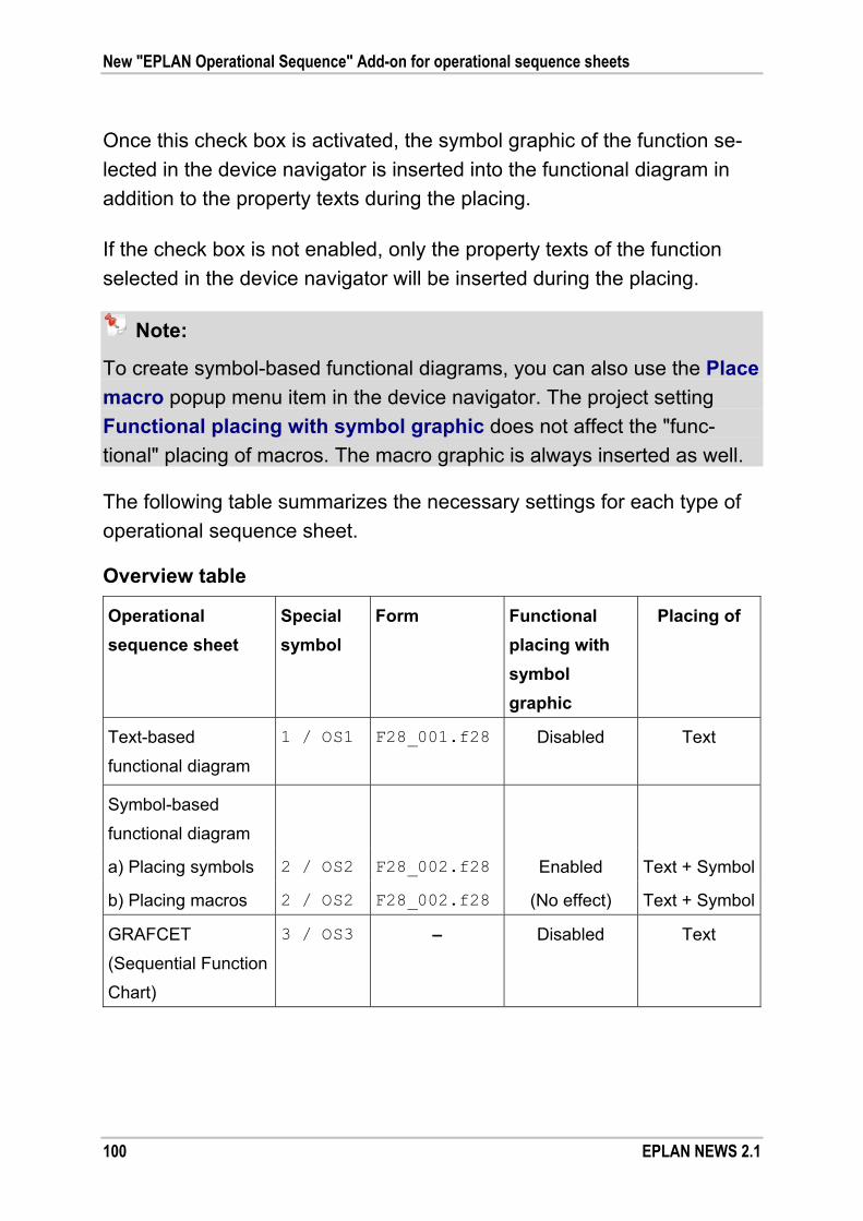
New "EPLAN Operational Sequence" Add-on for operational sequence sheets
100 EPLAN NEWS 2.1
Once this check box is activated, the symbol graphic of the function se-
lected in the device navigator is inserted into the functional diagram in
addition to the property texts during the placing.
If the check box is not enabled, only the property texts of the function
selected in the device navigator will be inserted during the placing.
Note:
To create symbol-based functional diagrams, you can also use the Place
macro popup menu item in the device navigator. The project setting
Functional placing with symbol graphic does not affect the "func-
tional" placing of macros. The macro graphic is always inserted as well.
The following table summarizes the necessary settings for each type of
operational sequence sheet.
Overview table
Operational
sequence sheet
Special
symbol
Form Functional
placing with
symbol
graphic
Placing of
Text-based
functional diagram
1 / OS1 F28_001.f28 Disabled
Text
Symbol-based
functional diagram
a) Placing symbols 2 / OS2 F28_002.f28 Enabled Text + Symbol
b) Placing macros 2 / OS2 F28_002.f28 (No effect) Text + Symbol
GRAFCET
(Sequential Function
Chart)
3 / OS3 – Disabled Text

New "EPLAN Operational Sequence" Add-on for operational sequence sheets
EPLAN NEWS 2.1 101
Create functional diagrams
A functional diagram can be created on an existing page or on a sepa-
rate new page. If you create a new page for a functional diagram, we
recommend that you use the "Overview" page type.
In the page properties of such a new page, enter the form to be used in
the Form name property. For functional diagrams, we provide you in the master data with the following two forms of the "Graphic (*.f28)" type:
Form F28_001.f28: for text-based functional diagrams
Form F28_002.f28: for symbol-based functional diagrams.
Since the forms supplied by us are based on a grid of 3 mm, enter for this page the value 3.00 mm in the Grid page property.
Place functions in the diagram
The central dialog for inserting EPLAN functions into a functional or
GRAFCET diagram is the device navigator. For this purpose, it does not
matter whether the function has already been placed in the schematic or
whether it is generated as a new, not yet placed, device via the New
device popup menu item.
Make entries in the properties for functions that are to be placed in the
functional diagram. By default, the values of the Displayed DT, Func-
tion text and State properties are output for a function. The properties
of a function displayed in the functional diagram depend on the special
symbol selected (see section "Preconditions" on page 98).

New "EPLAN Operational Sequence" Add-on for operational sequence sheets
102 EPLAN NEWS 2.1
It is crucial for a functional diagram to be able to indicate the state of a
plant or a device. For this purpose, you can use the new indexed prop-
erty State [1-10] (ID 20285), which you can select in the Properties dia-
log of a device via the Property selection dialog.
The State 10 property has been set aside, by default, for the input of
variables for GRAFCET diagrams (see section "Insert table of variables"
on page 108), but can also be used for other purposes.
To place a function on the open page, select the function in the device
navigator and then select the Place > Functional popup menu items.
Subsequently, the property texts (Displayed DT, Function text, etc.) and
– depending on the already mentioned Functional placing with symbol
graphic project setting – the symbol graphic of the function will hang on
the cursor and can be placed by you in the diagram.
During placing, the different property texts and – if also placed – the
symbol graphic of the function are combined into a group. This way, you
can edit, move or delete these properties jointly.
Place macros in the diagram
When creating symbol-based functional diagrams, you have the option
of placing the graphic of a part macro in the functional diagram. For this
purpose, select in the device navigator a main function on which a macro
has been stored via the part, and select in the popup menu the Place
macro > Functional menu items.

New "EPLAN Operational Sequence" Add-on for operational sequence sheets
EPLAN NEWS 2.1 103
As part of this action, the functions underlying the macro are internally
converted to a graphic. In the process, the first available representation
type and the first available variant of the macro are used. The grouped
graphic of the macro and the property texts of the main function hang on
the cursor and can be placed in the diagram by you.
Further information regarding the placement of symbol / macro graphics
When placing additional symbol / macro graphics in symbol-based func-
tional diagrams, you must note the following:
During placing, you can use the [Tab] key to "leaf through" the va-
riants of the symbol / macro. Using the [SHIFT] + [Tab] shortcut key,
you can "leaf through" the representation types while placing macros.
In the placing of a function, the symbol of the function currently se-
lected is used. If you have selected in the navigator tree a device hie-
rarchy level, the symbol of the first main function will be used. When
placing macros, it is always the part macro of the main function that is
used, regardless of the function selected.
If there is no symbol available for the function selected, or if no part
macro has been stored, you will be prompted to select a symbol or
macro. If you confirm this prompt with [Yes], a relevant selection
dialog will open.
If a symbol graphic / macro graphic is larger than stated in the Target
size for symbol / macro graphic project setting, the graphic will be
scaled (reduced in size). Enlargement is not an option in this context.
In addition, using the Position for symbol / macro graphic project
setting, you can define the offset for the position of the symbol / macro
graphic to be placed. Base point for the offset is the insertion point of
the special symbol for the property placement.

New "EPLAN Operational Sequence" Add-on for operational sequence sheets
104 EPLAN NEWS 2.1
Insert values for scale and process sequences
After you have placed the functions from EPLAN in the left, describing,
area of the functional diagram, you must then insert the values for the
time / step scale as well as the process sequences into the diagram.
The forms supplied already contain a time / step scale. Values for the
scale can be inserted, for example, by means of a macro. For this pur-pose, we provide you in the master data, in the OS_ESS macro subdirec-
tory, with the Numbers.ema macro with sample values.
You must draw the process sequences using graphical elements
(e.g., polylines).
Insert typical elements of functional diagrams
EPLAN provides support to enable you to insert some typical elements
of functional diagrams faster. Arrows, signal points, AND and OR opera-
tions can be drawn in the respective functional diagram by means of the
corresponding menu items via the Insert > Operational sequence
sheet menu path. Alternatively, you can also use the new Operational
sequence sheet toolbar and click the following buttons:
(Arrow)
(Signal point)
(AND condition)
(OR condition).
In addition, we supply a few window macros with special elements (such
as page transitions, various signaling elements, etc.). You will find them, after installing the new version, in the OS_ESS macro subdirectory.
New "EPLAN Operational Sequence" Add-on for operational sequence sheets
EPLAN NEWS 2.1 105
New representation type "Functional"
During the "functional" placing of functions in functional and GRAFCET
diagrams, a copy is created of a selected function, which is managed as
an auxiliary function. Such an auxiliary function contains the new repre-
sentation type "Functional". In the device navigator, the corresponding
functions are identified by a special icon ( ).
In the graphical editor, functions placed in a functional diagram are
placed as an auxiliary function, i.e., without the Part tab. Double-clicking
the relevant symbol or the placed property texts opens the familiar prop-
erty dialog. The entry "Functional" is set in the Symbol / Function data
tab in the Representation type field.
Functions with the "Functional" representation type can be placed mul-
tiple times. This means that the symbol or property texts of a function
can be placed multiple times in the functional diagram (e.g., on different
pages). For this reason, functions of this representation type are ignored
by the check run 007004 "Duplicate connection point designation:
%1!s!".
Global editing of properties
The new "Functional" representation type is also taken into account
during the global editing of properties and when creating reports. The
sequence of representation types determines which data of a shared
property is imported during global editing.
To learn about the exact sequence of representation types, visit the
online help and locate the section "Sequence of Representation Types
for Global Editing and Reporting".

New "EPLAN Operational Sequence" Add-on for operational sequence sheets
106 EPLAN NEWS 2.1
Data synchronization between representation types
Depending on the editing sequence, there may be differences between
the "Functional" representation type and the other representation types
of a function. The synchronization functions under Utilities > Synchron-
ize > Functions now also take into account the "Functional" representa-
tion type (e.g., synchronization via the Multi-line --> all representation
types menu item). This way, differences between functions displayed in
a distributed manner can be fixed.
Representation type for symbols
The "Functional" representation type is also accessible when you create
symbols in the symbol editor. This new representation type is offered to
you as a possible value for selection in the symbol properties for the
Symbol representation type (encoded) property.
This allows you to create your own special symbols for functional dia-
grams without graphic and with modified property placement.
Create GRAFCET diagrams
GRAFCET diagrams are representations of sequential controls, for which
the specification language GRAFCET (GRAphe Fonctionnel de Com-
mande Etapes / Transitions) according to DIN EN 60848 has been used.
The approach for creating GRAFCET diagrams is similar to the approach
for functional diagrams. The representation of such a sequential control
can be realized on an existing or new page. It is not necessary to store a
form.

New "EPLAN Operational Sequence" Add-on for operational sequence sheets
EPLAN NEWS 2.1 107
Example:
The following figure shows the schematic layout of a GRAFCET
diagram.
A —— GRAFCET table
Variable DT Function text
B —— Zv -P1 Pump
Zu 1-1A1 Cylinder
The table of variables is displayed in the area A. The heading and table
header are created by means of a macro. A single table row B with the
property texts (variable, DT, etc.) is inserted via the functional placing
from within the device navigator. The structure and interpretation of the
GRAFCET diagram are displayed in the area C. The GRAFCET ele-
ments steps, actions, and transitions can be inserted via the GRAFCET
menu.

New "EPLAN Operational Sequence" Add-on for operational sequence sheets
108 EPLAN NEWS 2.1
Insert table of variables
On the desired page, insert a table for the variables of the GRAFCET
diagram. The table header of this table is inserted by means of a macro. To do so, select from the previously mentioned OS_ESS macro subdirec-
tory the window macro Table_GRAFCET.ema and then place it.
A single table row with the property texts of a function (variable, dis-
played DT, function text, etc.) can be inserted from the device navigator
via the Place > Functional popup menu items. The property arrange-
ment of the texts is defined by the special symbol stored in the project settings. The special symbol OS3 gives the row its graphical framework.
Notes:
If you use the special symbol OS3, the value of the State 10 property
is placed as the variable text.
Usually, the devices predefined in EPLAN are placed only textually in
the variable table of the GRAFCET diagram. This means that, in this
context, the Functional placing with symbol graphic project setting
must be deactivated (see section "Settings for operational sequence
sheets" on page 99).
Insert GRAFCET elements
The essential elements of a GRAFCET diagram are steps, related
actions and transitions.
Steps
A step identifies the state of a part of the sequence. Steps must have
a designation to be identifiable. The recommended representation of a
step in the diagram is a square.

New "EPLAN Operational Sequence" Add-on for operational sequence sheets
EPLAN NEWS 2.1 109
Actions
A step can be allocated one or several actions. An action defines what
is to be done to a variable. Actions are generally represented by rec-
tangles.
The variables can be combined in a variable table transparently. Via
the additional placing of device tags in this variable table, a connec-
tion to the EPLAN devices is established.
Transitions
A transition marks the transfer from one step to the next. In the dia-
gram, a transition is mostly represented by a line perpendicular to the
connection between the two steps.
A transition may contain a name; it must be placed on the left and
must be inside brackets. The transition condition is placed to the right
of the transition.
In all types of sequences, steps and transitions must alternate constant-
ly. Please see the DIN EN 60848 standard for information on the correct
layout and meaning of the individual elements of a GRAFCET diagram.
EPLAN supports the quick and easy insertion of these GRAFCET
elements. Select from the Insert > Operational sequence sheet >
GRAFCET menu path the menu items Step, Step with transition,
Action, Action with connection and Transition.
Alternatively, you can click the following buttons in the new Operational
sequence sheet toolbar:
(GRAFCET step)
(GRAFCET step with transition)
(GRAFCET transition)
(GRAFCET action)
(GRAFCET action with connection).

New "EPLAN Operational Sequence" Add-on for operational sequence sheets
110 EPLAN NEWS 2.1
All these GRAFCET elements are available to you also as a window macro in the previously mentioned OS_ESS macro subdirectory. In addi-
tion, using the Arrows.ema macro, you can also insert prefabricated
arrows in a GRAFCET diagram.
Tip:
When, while pasting a GRAFCET element, you press the [Tab] key, you
can "leaf through" various preconfigured variants. This way, by selecting
the corresponding GRAFCET element, you can insert, for example, initial
steps, inclusive steps, macro steps, etc. You can do this also with the
action and transition. Corresponding combinations, such as step with
transition, continue to be available.
Describing texts
The asterisk (*) in the GRAFCET elements inserted shows you that you
can enter in this space texts such as step names, transition names or
conditions or an action identifier. The different objects of a GRAFCET
element are combined into a grouping.
In order to enter a single text directly without undoing the grouping, keep
the [SHIFT] key pressed and then open the Properties - Text dialog by
clicking the respective asterisk.
You can insert additional information (e.g., comments, which must be
placed in quotes) in the GRAFCET diagram as graphical texts.
Tip:
Using the C variant of the special symbol OS3, you can place only the
displayed DT of the selected device. The D variant allows you to place
only the variable of the highlighted device. This way you can insert the
device tags or variables also as texts in the sequential control of a
GRAFCET diagram.

New "EPLAN Operational Sequence" Add-on for operational sequence sheets
EPLAN NEWS 2.1 111
New special characters for GRAFCET
In order to enable you to have access to special characters while creat-
ing texts in GRAFCET diagrams, the Special characters dialog has
been extended to include the following special characters:
Arrow up (↑)
Arrow down (↓)
Not equal to (≠).
To access these special characters when entering text or in specific text
fields, click in the relevant field and select the Special characters popup
menu item.
Note:
Please note that some special characters are not available for all fonts.
If you wish to use these special characters, you must select the appro-
priate fonts from the Settings: Fonts dialog.
Special Topics EPLAN PPE
112 EPLAN NEWS 2.1
Special Topics EPLAN PPE
Display the DT of PCT loop elements in the functional view
Previously, the PCT loop elements sorted into the tree of the functional
view navigator could be displayed only according to the designations
Device type, Component, Device field, or other properties (e.g., P&I
diagram). In this new version, you can now also display the device tag of
an assigned function in the tree.
Benefit: Select your own identifying property for display on the PCT
loop element. The display of the device tag simplifies the
orientation in the functional view. You can see all the informa-
tion at a glance thanks to the direct display of the properties
in the functional view. The time-consuming search for all this
information in other dialogs is no longer necessary, and you
save time.
For this purpose, the View dialog, which you can open from the function-
al view navigator via Popup menu > View, has been extended. Here
now, you can use a new drop-down list for the PCT loop element field
with the following entries:
<empty entry>
DT (identifying)
DT (identifying, without project structures)
DT (displayed)
DT (full).
Special Topics EPLAN PPE
EPLAN NEWS 2.1 113
If from the drop-down list you have selected "DT (<...>)", the display in
the tree view of the functional view is updated, and the corresponding DT
is displayed next to the entry selected in the PCT loop element field as
"<DT>".
Example:
In the sample project EPLAN-PPE-DEMO, you have adjusted the settings
Device type and DT (displayed) for the view of the PCT loop ele-
ments. In this case, the tree of the functional view navigator will display
the following as the designation of a PCT loop element, for example: Measuring transducer <+S1 T3-D9>.
Filter in EPLAN View according to PI Code
If you open an EPLAN PPE project in EPLAN View, and navigate into the
list of the functional view navigator, then you can now filter here also
according to the PI code.
In the list view of the navigator, click the [...] button for the Filter field,
and the Filter list dialog opens. In this dialog, the PI code field is now
also validated in EPLAN View. Via [...], you can select all PI codes that
exist in the project and, thus, filter the plant elements according to a
specific PI code.
Automatic PCT loop numbering
The Adjust PCT loop structure dialog opens when you copy and paste
PCT loops in the functional view navigator, when you paste copied P&I
diagram pages or page sections, and when you paste P&I diagram
macros. When sorting PCT loops into the existing PCT loop structure,
you now have the option of automatic PCT loop numbering.

Special Topics EPLAN PPE
114 EPLAN NEWS 2.1
Benefit: Numbering at the push of a button facilitates the correct num-
bering by way of the automatic determination of the next
available PCT loop number. In combination with the possible
default setting of start values and increments for the number-
ing and identification of PCT loops (defined in the settings),
you control project-wide the standardized assignment of PCT
loop numbers. The quality of projects increases, because dup-
licate PCT loop numbers or unwanted gaps in the number
ranges of the PCT loops are prevented in advance.
For this purpose, you can now also use the new Automatic menu item
below the [Number] button. The Manual menu item corresponds to the
previous numbering using the subsequent Number dialog.
If you select the Automatic menu item, the highest available PCT loop
number relative to the PI code will be calculated, and the next higher
number / next higher numbers is / are suggested for the Number col-
umn.

Special Topics EPLAN PPE
EPLAN NEWS 2.1 115
Note:
Please note that the numbering behavior of PCT loops is affected by the
settings under Options > Settings > Projects > "Project name" > PPE
> PCT loops. In the PCT loop numbering group box, you can set the
start value and increment for the numbering. Whether EPLAN PPE ac-
cepts for the above actions identical PCT loops project-wide or in relation
to the plant depends on the settings in the Identical PCT loop numbers
group box.
Sort in connection with the selection of PCT loops
When pasting macros or schematic areas with PCT loops, in the Adjust
PCT loop structure dialog click a cell of the Number column, followed
by the [...] button; then, the Select PCT loop dialog opens. The PCT
loops displayed in this dialog are now – like in the functional view navi-
gator – sorted according to their measurand, processing function, and
number.
Benefit: The sorting helps you through improved transparency in using
existing PCT loop numbers when you place schematic areas
with PCT loops in EPLAN PPE P&ID.
Synchronize structure identifiers automatically when inserting macros
In the Settings: Structure identifier dialog, Version 2.0 SP 1 comes
with a new setting (menu path: Options > Settings > Projects > "Pro-
ject name" > PPE > Structure identifiers). The Automatically syn-
chronize structure identifiers after the insertion of macros check box
is activated by default.
Special Topics EPLAN PPE
116 EPLAN NEWS 2.1
Using this setting, you control that, when inserting macros with PCT
loops, the devices assigned and contained in the macros are given struc-
ture identifiers automatically that have been determined on the basis of
the EPLAN PPE settings for the structure identifiers. If the setting is not
set, the devices keep the structure identifiers defined in the macros.
Benefit: The use of templates / macros and the automatic application
of project-specific structure identifiers through the assignment
of functional plant structure accelerates project editing and im-
proves the quality of the documentation. Preplanning informa-
tion can be applied to "Detail Engineering" without additional
efforts and thus automatically ensures consistent project data
across all project design phases. The specific method (setting)
you choose crucially depends on the desired workflow.
Draw extended DT adoption at PCT loop
Frequently, device tags are defined already in the preplanning of field de-
vices or supplementary automation components. Some of these devices
are also placed in plant overviews (P&I diagrams), or, in a purely data-
base-specific manner, defined in the function plant structure. The EPLAN
platform now offers extended options to apply this key information from
the preplanning in connection with the automatic drawing of schematics
to "Detail Engineering".

Special Topics EPLAN PPE
EPLAN NEWS 2.1 117
Benefit: The EPLAN platform ensures that this information and the dif-
ferent representation types of the devices are kept consistent
in the further process of the project. The designer is supported
by the automatic adoption of the preplanning information –
time-consuming manual synchronization is no longer neces-
sary.
The automatic synchronization guarantees the quality of the
entire machine and plant documentation at all times. EPLAN
PPE eliminates at this point the frequent system discontinuity
between preplanning and "Detail Engineering".
As a requirement for the DT adoption during the drawing of the PCT
loop, the DT adoption from existing function setting must be activated
(under: Options > Settings > Projects > "Project name" > PPE >
Devices).
If one or several functions or function templates are assigned (in the
Functions tab) to a plant, PCT loop, PCT loop function, or PCT loop
element (without specification), executing the Draw PCT loop popup
menu item (in the Pages tab) will now automatically apply the existing
or already-assigned device tags of the functions at the PCT loop to the
appropriate functions in the macro assigned. This works also when the
function of a device has already been placed in a different representation
type.
This way, it is possible to place a function (e.g., a drive), which has al-
ready been placed on a page of the "P&I diagram" type, in the schematic
in a different representation type. In the process, the DT already defined
in the P&I diagram for the drive is applied to the schematic.

Special Topics EPLAN PPE
118 EPLAN NEWS 2.1
Extended EPLAN PPE P&ID AutoCAD interface
The EPLAN PPE P&ID AutoCAD interface allows for the exchange of
data between EPLAN PPE and AutoCAD to create plant overviews
(P&ID, P&I diagrams, etc.) in AutoCAD. This interface now also supports
the 64-bit version of AutoCAD 2011.

EPLAN Pro Panel Professional
EPLAN NEWS 2.1 119
EPLAN Pro Panel Professional
Note:
EPLAN Pro Panel Professional is available both as an option and as an
add-on variant for EPLAN Electric P8 Select and EPLAN Electric P8
Professional, and is also available as a standalone variant.
As an application for the area of integrative enclosure design, fabrication
and manufacture, we now introduce to you our new solution "EPLAN Pro
Panel Professional" together with the current EPLAN platform.
Benefit: Automatizations as well as machine and plant design profit
from this new interdisciplinary engineering tool for enclosure
and switchgear design that covers all trade-specific require-
ments. Planning, 3D layout, manufacturing, and mounting
merge, through a uniform data basis, to form a fully integrated
solution. This accelerates the product creation process –
declining costs and rising added value are preprogrammed.
Uniform data – synchronized automatically
Integration is the keyword that combines all the processes of the EPLAN
platform. The devices planned in electronics planning can now be used
directly for the 3D mounting layout. The otherwise-customary data syn-
chronization of the programs involved or the complex feedback of bill of
materials information is now a thing of the past.
The processes of product development in enclosure engineering are
accelerated significantly; after all, redundant data management has been
eliminated and, thus, also many related work steps and the typical efforts
in connection with "Reverse Engineering". At the same time, potential
errors in project synchronization can be prevented right from the start.
EPLAN Pro Panel Professional
120 EPLAN NEWS 2.1
In addition, key basic functions of the EPLAN platform such as Revision
control, Rights management, or special programming by way of the
EPLAN API can be used to the fullest extent, but this is not all by a long
shot: Integration moves on in the direction of manufacturing, mounting,
and wiring. Direct data transfer to NC machines, conductor routing, and
cable fabrication ensure the seamless workflow across the entire product
creation process.
Reliable planning – correct manufacturing
Whether dynamic collision check or automatic checking of relevant in-
stallation conditions: the software makes professional 3D layout planning
easy even for the occasional user. Manufacturing-relevant data on drill
holes or milling are taken into account in the 3D model and can be edited
further. Besides associated mounting diagrams, special drilling templates
can also be created.
Another decisive practical advantage: In the creation of master data,
manufacturing information is stored only once – even for length-variable
parts such as cable ducts or mounting rails. Subsequently, components
and NC data are integrated automatically with the respective 3D mount-
ing layout; this ensures fast results and constant quality. For each NC
interface, modifications to housings, doors or mounting panels are
transferred simply to appropriate manufacturing systems – Steinhauer
and Perforex are just some of the examples of the deep manufacturing
integration and the available interfaces.
Flexible cable routing
More flexibility in 3D conductor routing: Aside from conductors, cables,
too, can be routed within a 3D mounting layout. Path networks can be
defined in a space and connections routed intuitively – if so desired,
independent of the defined wire ducts.

EPLAN Pro Panel Professional
EPLAN NEWS 2.1 121
New routing ranges extend the variety of 3D routing and support virtual
and automated wiring (e.g., of Lütze frame systems). By way of so-called
"wiring cut-outs", it is possible to route wires and cables, for example on
the back of mounting panels, partitions, or other enclosure items – in-
cluding short paths.
The results determined by length-optimized wiring and cabling of compo-
nents are used to optimize the schematic – keyword: net-based wiring.
Data – the be-all and end-all of engineering
Where would engineering be without the appropriate device data?
EPLAN Pro Panel Professional offers a variety of options for accessing
device data. Even 3D geometric data is not a problem. This is handled
by the integrated STEP interface. Whether adopted directly from the
component manufacturer, from any 3D CAD programs, or via various
data portals and data CDs (such as RiCAD-3D from Rittal), the STEP
data is imported in EPLAN Pro Panel Professional and, partially auto-
matically or interactively, converted to qualified EPLAN macros for the
3D mounting layout. Totally new in this context is the support for the
EPLAN accessory selection.
Selectively extended and adjusted to the specific requirements of the
users working with the 3D mounting layout, the accessory components
can be defined and stored, e.g., for enclosures or devices – including
component know-how and permitted combinations.
EPLAN Cabinet customers score two benefits. After all, they can con-
tinue using the existing EPLAN Cabinet data in EPLAN Pro Panel Pro-
fessional. The XL variant of EPLAN Pro Panel provides for extensive
functions for applying existing data and its integration with the EPLAN
platform.

EPLAN Pro Panel Professional
122 EPLAN NEWS 2.1
In perfect harmony with EPLAN Cabinet, EPLAN Pro Panel Professional
adopts all significant parts data such as 3D graphical macros, 3D enclo-
sure templates or parts of the EPLAN Cabinet accessories management
– the latter, of course, including integration with the accessory selection
of the EPLAN platform.
3D mounting layouts from EPLAN Cabinet cannot only be adopted, but
they can also be integrated with the underlying EPLAN Electric P8 pro-
jects directly and automatically, if so desired. Component connections
between the schematic and 3D mounting layout are established.
Since EPLAN Cabinet accesses the very same EPLAN parts database
like all other EPLAN platform programs in order to create and maintain
parts data, existing parts data can still be used in EPLAN Pro Panel
Professional directly and without data migration.
Finally, EPLAN Pro Panel Professional also ensures the adoption of
manufacturing-based data that has been defined in EPLAN Cabinet. This
is true of part drilling and conductor connection point patterns of devices,
as well as of freely defined, NC-machine-specific outlines for cut-outs
and recesses.
With its deep integration, the EPLAN Pro Panel Professional version
sustainably speeds up parallelized engineering on a uniform data basis.
The bottom line is this: elimination of need for data conversion, data
checking and "Reverse Engineering"; decreasing costs, rising quality,
reduced "time-to-market", and sustainable investment security.

EPLAN Pro Panel Professional
EPLAN NEWS 2.1 123
EPLAN Pro Panel Professional – extended functionality
Aside from the basic functions already available for 3D mounting layout
in EPLAN Pro Panel, the following components have been added to the
extended functionality of the Professional version:
Extended functionality for the 3D mounting layout
NC data – definition, management and project integration of:
– Part-specific drilling patterns – Individually defined drill holes, cut-outs and arrangements
NC outline editor to create specific NC outlines and machine-specific
NC records
One-to-one output of drilling templates in PDF format for manual
editing of enclosure items
Extended accessories management
Additional item types – busbars, C-profiles, user-defined profiles
Definition and equipment of busbar systems
Extended creation of master data
Extended and automated definition of the device logic
Additional reports for production and mounting
Data transfer of EPLAN Cabinet data
Availability and installation as add-on or standalone variant.
EPLAN Pro Panel Professional
124 EPLAN NEWS 2.1
EPLAN Pro Panel Professional can be installed as follows:
Add-on installation:
As part of an add-on installation, EPLAN Pro Panel Professional
is added to an existing EPLAN Electric P8 installation. EPLAN
Electric P8 Select and EPLAN Electric P8 Professional can thus be
extended in a modular manner to include special functionalities for
the 3D mounting layout and the creation of 3D models, including
NC manufacturing data.
Other meaningful additions to this combination of EPLAN Electric P8
and EPLAN Pro Panel Professional are EPLAN platform add-ons
such as EPLAN Project Management, EPLAN Multi Language Trans-
lation, EPLAN Project Reference, EPLAN User Rights Management,
EPLAN API Extension, and, if necessary, also EPLAN Net Based
Wiring.
Standalone installation:
This variant offers you extensive functions for creating and editing
schematics in connection with electrical engineering EPLAN projects,
for the 3D mounting layout, and the creation of 3D models including
NC manufacturing information.
Unlike the add-on installation, the standalone variant of EPLAN Pro
Panel Professional cannot be extended in a modular fashion to in-
clude add-ons of the EPLAN platform, such as EPLAN Project Man-
agement, EPLAN Revision Management, EPLAN Multi Language
Translation, or EPLAN Change of Standard.
Note:
A detailed account of the EPLAN add-ons that are used in connection
with EPLAN Pro Panel Professional can be obtained from the perfor-
mance description for EPLAN Pro Panel Professional.

EPLAN Pro Panel Professional
EPLAN NEWS 2.1 125
In the following section, we will first discuss the modularization of EPLAN
Pro Panel Professional, and then introduce you to some of the key new
functions. For more information on this and other functions, go to the
online help and look up the section "EPLAN Pro Panel".
Here is an overview of the topics:
"Modularization of EPLAN Pro Panel Professional" (see page 125)
"Manufacturing data for NC machines" (see page 128)
"Generate routing connections" (see page 129)
"Manufacturing data for wire fabrication machines" (see page 138)
"Mounting list report" (see page 138)
"Support with master data creation" (see page 140)
"Import and export of data" (see page 142)
"Data transfer from EPLAN Cabinet" (see page 144).
Modularization of EPLAN Pro Panel Professional
The module package EPLAN Pro Panel Professional can be extended
optionally to include the following add-ons:
EPLAN Production NC <Interface name>:
These NC interface modules transmit the coordinates and dimensions
of drill holes, cut-outs or locked areas (only in the case of Perforex
machines), as well as other production data to edit mounting panels,
doors or side sections directly on NC drilling and milling robots.
The following add-ons can be licensed as interfaces with NC
machines:
– EPLAN Production NC DXF (independent of manufacturer) – EPLAN Production NC Perforex (Manufacturer Kiesling) – EPLAN Production NC Steinhauer (Manufacturer Steinhauer).

EPLAN Pro Panel Professional
126 EPLAN NEWS 2.1
EPLAN Process Wiring:
On the basis of the planned schematic, you can use this add-on to
automatically and interactively define routing path networks in the
3D model and to generate 3D routing connections between the items
placed in the layout space.
Connections can be run through wiring cut-outs when being routed
on the back of mounting panels, partitions or other enclosure items –
even if the enclosure model does not yet have any physical cut-outs
in those locations. The modeling of cut-outs in the mechanical design
normally required for the routing is no longer necessary.
The routing connections generated form the basis for different reports.
For example, it is possible to configure and output a "general wires
parts list". The exported file can be used by manufacturing machines,
which interpret this format, for the purposes of automatic cutting to
length, labeling and production of conductor ends. The following add-
ons listed here can also be used to create control files for directly
controlling wire fabrication robots.
EPLAN Production Wiring <Interface name>:
These add-ons allow for the output of production data for wire fabrica-
tion machines of various manufacturers as well as for sharing data
with service providers. In doing so, every manufacturer-specific wire
fabrication must be licensed as a separate interface. The following
license extensions are available:
– EPLAN Production Wiring CableCenter (Manufacturer Metzner) – EPLAN Production Wiring CadCabel – EPLAN Production Wiring KOMAX – EPLAN Production Wiring Steinhauer PWA – EPLAN Production Wiring Schleuniger EASY ProductionServer – EPLAN Production Wiring WuS-Tec.

EPLAN Pro Panel Professional
EPLAN NEWS 2.1 127
EPLAN STEP Export:
This add-on allows for the 3D graphic data of a layout space to be
output in the international STEP format (STandard for the Exchange
of Product Model Data). The exported data can be imported in ex-
ternal CAD programs and be visualized there, provided that the re-
spective external program is capable of STEP import.
Notes:
In the STEP export, only faceted 3D data of the EPLAN Pro Panel
model is transferred. Information on analytic curves, surfaces or
volumes is not output.
The "EPLAN STEP Export" add-on is available as an extended
license for EPLAN Pro Panel and EPLAN Pro Panel Professional
as an optional extra. EPLAN Project Processing:
Using this add-on, you can import data from external programs
(CAE systems, ERP systems, etc.) as well as manually created data on devices and connections in different file formats (*.txt, *.csv,
*.asc). Necessary additional information, e.g. the level in case of
multi-level terminals, are supplemented with EPLAN platform-specific
basic functionalities.
Based on the devices and connections thus imported, it is possible to
create a 3D mounting layout including routing connections from the
3D mounting layout navigator.
This function ensures that the enclosure and switchgear design can
process not only EPLAN project data, but also data from external CAE
or, for example, ERP systems in EPLAN Pro Panel Professional.

EPLAN Pro Panel Professional
128 EPLAN NEWS 2.1
Manufacturing data for NC machines
NC machines are drilling, cutting, and milling robots which convert plan-
ning information into production processes by means of a control pro-
gram. Mounting panels, doors, and other equipable enclosure com-
ponents are mostly manufactured by NC machines when it comes to
enclosure design. By means of EPLAN Pro Panel Professional, manu-
facturing data can be created for NC machines and exported using
appropriate interfaces.
Outlines are created graphically in the outline editor of EPLAN Pro Panel
Professional and equipped with the machine-specific information by ge-
nerating an NC record. In addition, drill holes and fins can be placed in a
milling outline. The outline editor is opened via the Utilities > Master
data > Outline (NC data) menu path, in the same way as plot frames
and forms.
In the 3D mounting layout, mechanical items such as mounting panels,
doors and / or side panels can be equipped with different, even freely
defined, cut-outs. Such manually placed openings are output, if neces-
sary, to NC machines or the so-called "drilling templates".
Drilling templates allow in EPLAN Pro Panel Professional for the output
of item views, including associated drilling patterns and cut-outs on a 1:1
scale in the form of a PDF file for each item and view – including infor-
mation on drilling coordinates.
These templates - printed on a plotter or large-format printer on a 1:1
scale - serve as templates for the manual drilling and editing of the
mounting panel. In EPLAN, this export is carried out via the Utilities >
Reports > Machining > Drilling template menu path.

EPLAN Pro Panel Professional
EPLAN NEWS 2.1 129
Using the NC-DXF interface, you can transfer the coordinates and di-
mensions of the drilling holes and other manufacturing data on the
editing of mounting panels, doors, and side panels directly to NC drilling
and milling robots, and have them used as a basis for machine program-
ming.
Using the NC-Perforex and NC-Steinhauer interfaces, you can generate
original NC machine programs especially tailored to a specific machine.
These can be used on Perforex and Steinhauer processing machines.
Complex manual extensions to the machine program are no longer
necessary.
The NC machine interfaces (DXF, Perforex, Steinhauer) are available
as add-ons. The NC export is carried out via the Utilities > Reports >
Machining > "Interface name" menu items.
Generate routing connections
The multi-line connections between the devices in the schematic serve
as a basis for determining the optimal routing tracks and wire lengths
within the 3D mounting layout. This way, 3D connections can be routed,
i.e., generated, between the logic items placed in a 3D layout space.
These connections of the "3D mounting layout" representation type are
called routing connections in the EPLAN platform. A routing connection
has all the properties that a multi-line connection has, but it also contains
information on its routing track.
Method for routing connections
Connections are routed in several consecutive steps:
Definition of multi-line connections in the schematic, assignment of a
part to the connection
Placement of 3D part placements of the objects involved in the layout
space

EPLAN Pro Panel Professional
130 EPLAN NEWS 2.1
Definition of a routing path network that is available for the routing of
the connection (formed automatically based on placed wire ducts,
etc.; can be supplemented interactively)
Generation of routing connections
Determination of the routing track (total number of routing paths, wir-
ing cut-outs or routing ranges that a connection routed in the layout
space runs through).
If the multi-line connection has an assigned wire part, the routing con-
nection will be visualized in color and diameter according to the default
from the part, and is thus also prepared for the ordering or manufacturing
of the wires.
In the following section, we assume that the first two steps have already
been completed. Only the further steps relevant to the routing will be
described.
Routing paths
A routing path network in which cables and connections are routed con-
sists of routing paths, routing ranges, and wiring cut-outs that are con-
nected to each other.
Routing paths are inserted default paths along which connections can be
routed. Graphically, the routing paths are displayed as blue lines with
snap points at the starting point, end point and the center.
There are automatic and manual routing paths:
Automatic routing paths:
When generating the routing path network, routing paths are gener-
ated automatically, making use of the placed wire ducts, routing
ranges, and cut-outs.

EPLAN Pro Panel Professional
EPLAN NEWS 2.1 131
Manual routing paths:
Routing paths can also be generated manually in order to extend the
routing path network outside of the wire ducts. This type of routing
paths defines the routing track by means of any starting and end
points of the user's choice.
Example:
The following figure shows a manually inserted routing path.
Routing ranges
In routing ranges, connections are not routed along a routing path;
instead, it is always the shortest possible and direct connection that is
routed. This way it is, for example, possible to implement wiring on the
back of a mounting panel.

EPLAN Pro Panel Professional
132 EPLAN NEWS 2.1
Items must not be inside or protrude into a routing range, because other-
wise collisions would occur, and these items would not be taken into ac-
count for routing purposes. This condition is checked by the check run
026036.
Wiring cut-outs
Wiring cut-outs are used to steer connections at the time of routing to
the back of mounting panels, partitions, or other enclosure items, without
there being a cut-out in the model of the item. Since this cut-out may be
inserted at a later time when the item is manufactured. A wiring cut-out
contains only a routing path. As a result, it can only receive connections
from one direction.
To insert a wiring cut-out, select the Insert > Wiring cut-out menu
items. Via a starting and end point, you define the wiring cut-out on an
activated area of a mounting panel or door. The wiring cut-out is inserted
in the item as a cuboid.
With each feed-through of a connection through a wiring cut-out, an extra
length is taken into account. For the extra length, there is a project-wide
default setting for routing connections in the project-specific settings. But
the extra length can also be set individually in the property dialog of each
wiring cut-out. For this purpose, you can use the Extra length (ID
36031) property.
Routing path network
The routing path network is the foundation for routing the routing connec-
tions. Following a modification of the course of the routing path – e.g., by
adding routing paths, routing ranges and / or wiring cut-outs – the routing
path network must be generated anew.
EPLAN Pro Panel Professional
EPLAN NEWS 2.1 133
To generate the routing path network for a 3D mounting layout in an
opened layout space, select the Project data > Connections >
Generate routing path network menu items. The information on all
routing paths found in the layout space is gathered and combined into a
routing path network. In the process, an automatic routing path is routed
through each wire duct.
Note:
A full report of the opened layout space is generated at the time the
routing path network is generated. It is also possible to select several
layout spaces in the layout space navigator in order to generate a joint
report of all of them. For this purpose, a separate routing path network
is calculated for each layout space; routing from one layout space to an-
other is not possible.
Display of the routing path view
To display the current valid routing path network in the opened 3D layout
space better, you can use the routing path view. To do so, select the
View > Connections > Routing path view menu items.
Subsequently, all ducts, routing tracks, wiring cut-outs, and routing paths
through which a connection can run are highlighted. The transparency of
all part placements in the layout space is set to 50% at the same time.
Thus, the routing path network is clearly visible. The routing path view
can be influenced by defining a connection filter.
Routing connections
During routing, 3D routing connections are generated between the 3D
part placements in the layout space. They define the route within the
routing path network that wires and cables follow. If there are no con-
nection points defined for a part placement, they will be generated auto-
matically prior to the routing.
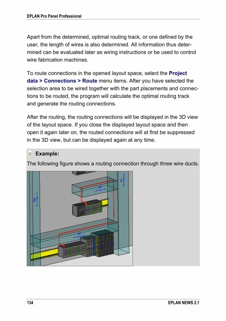
EPLAN Pro Panel Professional
134 EPLAN NEWS 2.1
Apart from the determined, optimal routing track, or one defined by the
user, the length of wires is also determined. All information thus deter-
mined can be evaluated later as wiring instructions or be used to control
wire fabrication machines.
To route connections in the opened layout space, select the Project
data > Connections > Route menu items. After you have selected the
selection area to be wired together with the part placements and connec-
tions to be routed, the program will calculate the optimal routing track
and generate the routing connections.
After the routing, the routing connections will be displayed in the 3D view
of the layout space. If you close the displayed layout space and then
open it again later on, the routed connections will at first be suppressed
in the 3D view, but can be displayed again at any time.
Example:
The following figure shows a routing connection through three wire ducts.
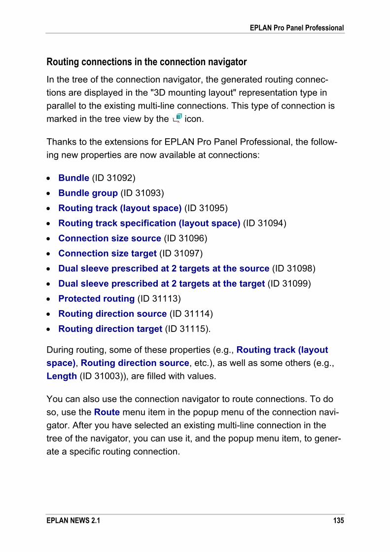
EPLAN Pro Panel Professional
EPLAN NEWS 2.1 135
Routing connections in the connection navigator
In the tree of the connection navigator, the generated routing connec-
tions are displayed in the "3D mounting layout" representation type in
parallel to the existing multi-line connections. This type of connection is
marked in the tree view by the icon.
Thanks to the extensions for EPLAN Pro Panel Professional, the follow-
ing new properties are now available at connections:
Bundle (ID 31092)
Bundle group (ID 31093)
Routing track (layout space) (ID 31095)
Routing track specification (layout space) (ID 31094)
Connection size source (ID 31096)
Connection size target (ID 31097)
Dual sleeve prescribed at 2 targets at the source (ID 31098)
Dual sleeve prescribed at 2 targets at the target (ID 31099)
Protected routing (ID 31113)
Routing direction source (ID 31114)
Routing direction target (ID 31115).
During routing, some of these properties (e.g., Routing track (layout
space), Routing direction source, etc.), as well as some others (e.g.,
Length (ID 31003)), are filled with values.
You can also use the connection navigator to route connections. To do
so, use the Route menu item in the popup menu of the connection navi-
gator. After you have selected an existing multi-line connection in the
tree of the navigator, you can use it, and the popup menu item, to gener-
ate a specific routing connection.

EPLAN Pro Panel Professional
136 EPLAN NEWS 2.1
Bundling of routing connections
Wires to be routed one after another or in parallel can be combined into
bundles and be used for wiring as labeled bundles. This speeds up the
wiring process and streamlines the entire enclosure manufacture and
mounting.
In EPLAN Pro Panel Professional, too, you can combine generated
routing connections into bundles. The bundles, then, can be organized
as bundle groups. It is important to note that a bundle must not be
assigned to several bundle groups. This can be checked at any time
through the check run 026033.
Routing connections can be bundled manually via the Bundle connec-
tion property (ID 31092), or also automatically via a corresponding func-
tion.
Using the interfaces for wire fabrication, you can evaluate this informa-
tion and transfer it to the manufacturing robots that produce individual
wires or finished fabricated and labeled bundles.
Optimization of nets
If the routing track resulting from the routing is not optimal, or if the
routing track was affected by a modification to the routing, you can
optimize this routing track.
After you have highlighted the generated routing connections, e.g., in the
connection navigator or the opened layout space, select the Project da-
ta > Connections > Optimize nets automatically menu items. In the
Optimize nets automatically dialog that then opens, define the settings
for net optimization.
The result of the net analysis will be displayed in the Optimize nets
automatically: Preview of result dialog. All connections in this dialog
with the status "New" are re-routed during the subsequent optimization.

EPLAN Pro Panel Professional
EPLAN NEWS 2.1 137
During the automatic optimization, the connections will be modified as
follows:
All connection points continue to be connected.
The sum of the wires to be routed is as short as possible.
No more than 2 connections terminate in a connection point.
A daisy chain is always generated.
Customization of the schematic
Based on the determined wiring sequence in the virtual 3D prototype of
the enclosure, the connections in the schematic can also be optimized
and re-numbered accordingly. In the process, the existing connections
are corrected in the schematic "logically". This creates one or several
nets with net-based connections for which net definition points have
been inserted in the schematic.
Note:
In order to edit the optimized nets in the multi-line schematic further via
the net definition points, use the "EPLAN Net Based Wiring" add-on. This
module is available as an option for EPLAN Electric P8 Professional.
Tip:
You can also use the corresponding buttons of the Pro Panel routing
toolbar to define the routing path network, to route connections, and to
optimize nets.

EPLAN Pro Panel Professional
138 EPLAN NEWS 2.1
Manufacturing data for wire fabrication machines
You can output a "General wires parts list" based on the routing connec-
tions generated in the layout space. This file can be used by fabrication
machines, which interpret this format, for the purposes of automatic cut-
ting to length and fabrication of conductor ends.
In addition, EPLAN Pro Panel Professional allows for the output of manu-
facturing data for wire fabrication machines of the following manufactur-
ers and service providers:
CadCabel
Komax
Metzner (Triathlon Kabelcenter)
Schleuniger (Easy Production Server)
Steinhauer (Personal Wiring Assistant)
Wus-TEC.
Each of these machine or service provider interfaces listed must be li-
censed separately via an appropriate add-on "EPLAN Production Wiring
<Interface name>".
Mounting list report
In EPLAN Pro Panel Professional, you can generate the Mounting list
report for 3D part placements of a layout space. Mounting lists are used
to map in a report the hierarchical structure of a 3D mounting layout in
the layout space. The report can be done for a very specific part place-
ment (mounting panel, enclosure, busbars, etc.).

EPLAN Pro Panel Professional
EPLAN NEWS 2.1 139
In such a function-based report, the 3D part placements are evaluated
for which the new Create mounting list (ID 36032) property has been
activated in the property dialog. This property can be selected via the
property selection for all 3D functions (except for mounting surfaces). For
devices with the activated property, all devices of the hierarchy level im-
mediately below are listed in the output mounting list. The listed objects
are sorted by legend item by default.
To create a mounting list, you can use the new "Mounting list" report type
available from the Select report dialog. As with other function-related
reports, too, when outputting the mounting list you can make a manual
selection. In the subsequent Manual selection dialog, all 3D part place-
ments are listed for which the Create mounting list property has been
activated.
Example:
If the Create mounting list property has been activated, for example,
for an enclosure, the device data of the enclosure will be output to the
header of the report. In the data area, all devices are listed that are ar-
ranged in the layout space in the hierarchy level immediately below this
enclosure.
For a mounting panel placed in this enclosure, the associated devices
located on a lower hierarchy level are not output. If this is to be done, the
Create mounting list property can be activated also for the mounting
panel. In this case, a second mounting list with the data of the mounting
panel and the devices placed on it will be output.
Forms for mounting lists
In creating the mounting list, the form is used that was specified in the
project-specific Settings: Output to pages dialog for the new "Mounting list (*.f32)" form type.

EPLAN Pro Panel Professional
140 EPLAN NEWS 2.1
You can select placeholder texts from the following elements for the
forms of this type in the Placeholder texts - Mounting list dialog:
Parts data
Part placements
Part reference data
Device data
Record.
The same placeholder texts are available for selection in both the header
and data area.
Filter for relevant devices in the layout space navigator
If you want to know which devices have been set aside for the genera-
tion of the mounting list, create a new filter for the layout space navigator
and select for this filter the new Create mounting list property as a filter
criterion.
Support with master data creation
Various functions in EPLAN Pro Panel Professional assist you in the
creation of master data. Some of these innovations are discussed in a
different section of this document. For more information on this, also
read the sections "Tree configuration for all main nodes" on page 22
and "Generate mounting surfaces" on page 43.
Automatic enclosure interpretation
Using the "Automatic enclosure interpretation" you transfer the existing
logic of an enclosure to another, newly to be defined, enclosure of the
same design. This substantially simplifies the working steps for creating
your own enclosure series, and also considerably reduces the asso-
ciated efforts.

EPLAN Pro Panel Professional
EPLAN NEWS 2.1 141
To save an imported 3D body in the opened layout space as an enclo-
sure, select the Edit > Device logic > Automatic enclosure interpreta-
tion menu items. The Select sample enclosure dialog opens after you
have selected the required 3D body. Here you select the enclosure that
you want to use as an interpretation template and whose properties you
want to apply to the enclosure geometry to be interpreted. Subsequently,
the item definitions and device logic of the sample enclosure are applied
to the new enclosure – including defined mounting surfaces, e.g., mount-
ing panels, doors, and side panels.
Finally, you create a 3D macro from the new enclosure and assign it to a
corresponding part in parts management.
Base points as special mounting points for accessory placement
In EPLAN Pro Panel Professional, a distinction is made between auto-
matically generated and user-defined base points. Automatic base points
are generated for all enclosures that are generated directly without
macro from the parts database (product group "Enclosure", product sub-
groups "Component" and "Body"). But there is also the option to store
user-defined base points in a macro and to use them as the property of
an accessory placement.
Base points are fixed defined mounting points in a layout space. These
special mounting points are a part of the device logic that are used when
working with enclosure accessories.
Using the base points, it is possible to install enclosure items (e.g., side
panels, bases, etc.) at a location that is fixed and defined or that may be
defined by the manufacturer. These items cannot be moved subsequent-
ly anymore. The placement is defined in parts management in the new
Accessory placement main node.

EPLAN Pro Panel Professional
142 EPLAN NEWS 2.1
Transfer a base point scheme
For enclosures that have been imported into the layout space as STEP
data, the base points necessary for the accessory placement can be
defined interactively.
For the Rittal enclosure systems "TS8", "AE" and "CM", EPLAN Pro
Panel Professional provides predefined schemes and functions for plac-
ing the base points automatically in a manner suitable for the enclosure
series. This facilitates the assignment of the base points substantially,
and reduces the efforts in terms of time to a minimum.
To do so, select the imported 3D graphic in the layout space or the
layout space navigator, and select the Edit > Device logic > Transfer
base point scheme menu items. The base points at the 3D graphic will
be defined automatically once you have set the name of the enclosure
series in the subsequent dialog.
Import and export of data
EPLAN Pro Panel Professional provides several functions for the import
and export of data.
Import data
You can import 3D graphics from external programs using the Layout
space > Import (3D graphic) menu items. The graphic data must be
provided in the common international STEP format (STandard for the
Exchange of Product Model Data).
With this import, you have the option of defining the degree of detailing
of the file to be imported (see section "Define degree of detailing for the
import of 3D graphical data" on page 38).

EPLAN Pro Panel Professional
EPLAN NEWS 2.1 143
Using two other functions, you can also import devices and routing con-
nections from other CAE or ERP systems, and then use such external
data to design your 3D mounting layout in EPLAN Pro Panel Profession-
al. Devices are imported via the Project data > Devices > Import menu
path. Routing connections are imported via the Project data > Connec-
tions > Import (routing connections) menu path. The following file
types are taken into account in connection with these imports:
Text file (*.txt)
Comma-delimited Unicode file (*.csv)
ASCII files (*.asc).
To import devices and routing connections, you will need an additional
license for the "EPLAN Project Processing" add-on.
Export data
The 3D graphic data of a layout space can be exported via the Layout
space > Export menu items to different formats (STEP, VRML).
As already mentioned elsewhere in this document, using the STEP sub-
menu item, you can output the graphical data in the STEP format (see
section "STEP export as a new extension" on page 45). For such export,
you must have an additional license for the "EPLAN STEP Export" add-
on.
Note:
In the STEP export, only faceted 3D data of the EPLAN Pro Panel model
is transferred. Information on analytic curves, surfaces or volumes is not
output.

EPLAN Pro Panel Professional
144 EPLAN NEWS 2.1
The export via the VRML submenu item generates a file in the VRML
format (Virtual Reality Modeling Language). To visualize in 3D and for
improved communications with other specialist departments, suppliers,
and customers, the exported data can be displayed in browsers, where
they can be rotated in full and zoomed.
The dialogs for the exports of 3D graphic data are similar to those of the
export dialogs known from the EPLAN platform (e.g., for DXF / DWG
export). You adjust the settings for the STEP and VRML export in the
user settings (subfolder Interfaces) in a settings dialog in each case.
Data transfer from EPLAN Cabinet
To secure your investment in the creation of EPLAN Cabinet data,
EPLAN Pro Panel Professional comes with a variety of powerful func-
tions for efficient data migration. This ensures that existing EPLAN
Cabinet data can continue to be used within the EPLAN platform.
Using the EPLAN Cabinet data transfer, you can transfer 3D project
data, NC data, master data and accessory parts from EPLAN Cabinet to
the EPLAN platform.
Note:
Since EPLAN Cabinet and EPLAN Pro Panel Professional access the
same EPLAN parts database, the existing parts data can continue to be
used in EPLAN Pro Panel Professional without data migration.
Data transfer from Cabinet projects
The project import transfers the graphic of the model space and 3D pro-
ject data from EPLAN Cabinet projects to existing or new EPLAN plat-
form projects. The import is executed via the Utilities > Data transfer >
EPLAN Cabinet > Project menu items.

EPLAN Pro Panel Professional
EPLAN NEWS 2.1 145
Upon import, the 3D mounting layout from EPLAN Cabinet is, if so de-
sired, integrated with a corresponding, eponymous or new EPLAN pro-ject. In this context, for each drawing file (*.zei) from EPLAN Cabinet, a
layout space is generated in the EPLAN project. The newly generated or
extended EPLAN project can then be opened and edited in the EPLAN
platform.
The Go to jump functions are supported across the layout space. As a
result, for example, all cross-referenced "parts" of a specific item or all
representation types of a specific function are linked to each, regardless
of whether these objects have been placed in the 2D or 3D view.
Data transfer of NC data
The milling outlines from EPLAN Cabinet stored in the NC database are
adopted via the NC data submenu item. In the process, every outline from the NC database is converted to an outline file (*.fc1) of the
EPLAN platform. The milling outlines are stored in the outline files as
NC records.
With this import, it is also possible to transfer, and to continue using them
in the future, the machines and machine settings defined in the NC data-
base from EPLAN Cabinet. A new synchronization between the EPLAN
platform and the NC processing machines is not necessary. These set-
tings are saved in the EPLAN platform as a scheme.
Data transfer of master data
Upon data transfer via the Graphical macro submenu item, the master
data (graphical macros, enclosure templates, enclosure items) is im-
ported in a new or existing EPLAN macro project. Through a correspond-
ing setting, you can generate 3D macros of the EPLAN platform auto-
matically from Cabinet graphical macros at the time of the data transfer.

EPLAN Pro Panel Professional
146 EPLAN NEWS 2.1
Data transfer of accessories
With this form of data transfer, the enclosure accessories defined in
EPLAN Cabinet are imported into EPLAN parts management. Accessory
placements are generated in parts management of the EPLAN platform
for accessory parts from EPLAN Cabinet. To execute this data transfer,
select the Accessories submenu item.
Notes:
For the data transfer of projects and master data from EPLAN
Cabinet, an executable EPLAN Cabinet installation Version 2.0 or
higher including a valid license must exist on the workstation.
The data transfer of views (user-defined views of the model space),
outlets in cable ducts, routed connections, NC machine specifications
of the "NC DXF" type, and NC user settings (for fins, behavior in case
of missing tools, post-processing) from EPLAN Cabinet is not possi-
ble! For the NC user settings, company settings with default values
are used in EPLAN Pro Panel Professional, to which you can make
minor adjustments.
For further details and more information on these functions, go to the
online help of the EPLAN platform and see the section "Data Transfer
from EPLAN Cabinet".

New Features in the EPLAN Data Portal
EPLAN NEWS 2.1 147
New Features in the EPLAN Data Portal
At the same time as the release of the new version of the EPLAN plat-
form, a new version of the EPLAN Data Portal with increased functional-
ity has also been released.
Our Internet portal for device data – the EPLAN Data Portal – provides
you with master data of major manufacturers for direct transfer to the
EPLAN platform. In addition to alphanumeric parts data, among other
information this master data also contains schematic macros, multilingual
parts information, preview images, documents, etc. The data, supplied
by the manufacturers, is directly integrated into the EPLAN platform
when downloaded.
Benefit: The EPLAN Data Portal simplifies considerably for the design-
er the integration of parts data with the engineering process.
While planning, he or she can directly access master data
that has been classified and checked for EPLAN compatibility,
without time-consuming searching of manufacture catalogs,
which thus reduces the project planning time.
High-quality master data facilitates uniform use in EPLAN and
increases the quality of the project documentation, from the
schematic, through detailed reports, to integration of manufac-
turer documentation (data sheets, operating manuals) in high-
quality manufacturing specifications. Detailed item data is of
crucial significance even in downstream use of documentation
during servicing and maintenance work.
The option to download each part and component selectively
ensures a clear structure and specific updating of your person-
al parts management.
New Features in the EPLAN Data Portal
148 EPLAN NEWS 2.1
To productively access the portal, you require the "EPLAN Data Portal"
add-on and a valid Software Service Contract for your EPLAN license.
For a quick part search, you can also go directly to the website
http://www.eplandata.de/portal/ after receiving the new version of the
EPLAN Data Portal.
This add-on can be used with the following variants of the EPLAN plat-
form:
EPLAN Electric P8 (Version 2.1)
EPLAN Fluid (Version 2.1)
EPLAN PPE (Version 2.1)
EPLAN Pro Panel Professional (Version 2.1)
EPLAN Education for Classrooms (Version 2.1).
Notes:
You must be connected to the Internet in order to use the EPLAN
Data Portal, and you must make sure that access is not prevented by
a firewall or any other security mechanism! If you have problems, you
should first check your firewall, virus scanner, or proxy settings.
Note that the EPLAN Data Portal has been released for Microsoft
Internet Explorer 8 and Internet Explorer 9.
After installation via the EPLAN Setup Manager, the add-on and its dia-
logs (navigator, settings, etc.) are integrated into the user interface of
the EPLAN platform. Once a user account has been created, open the
EPLAN Data Portal navigator by selecting the Data portal navigator
menu item from the Utilities menu.

New Features in the EPLAN Data Portal
EPLAN NEWS 2.1 149
An overview of the main new features of the EPLAN Data Portal:
Even more data and manufacturers
The amount and scope of item data in the EPLAN Data Portal is
constantly growing. Additional manufacturers (e.g., Endress+Hauser)
have been newly added to the list of over 30 component manufactur-
ers. Manufacturers already established in the portal are constantly
expanding the scope of their data in the EPLAN Data Portal.
Access via an Internet browser without logon
With the release of the new EPLAN platform, you now have access
to the EPLAN Data Portal via an Internet browser, even if you do
not design in EPLAN and are connected to the EPLAN Data Portal
through your EPLAN program variant.
In such a case, you can obtain information on parts in the EPLAN
Data Portal; productive access to the data, however, is not possible.
For example, you can import parts and insert macros or parts in the
graphical editor of the EPLAN platform only once you have started a
program variant of the EPLAN platform and logged onto the EPLAN
Data Portal.
This is how the parts of the manufacturers represented in the EPLAN
Data Portal are determined and presented as search results when you
look for the part or parts via a general Internet search (e.g., with
Google or other search engines).
New catalog "eCl@ss"
If you click the (Display catalog) button to view the parts in a cata-
log structure, you will now find an entry for eCl@ss in the Product
catalog drop-down list.
Select this entry, and the parts of the EPLAN Data Portal will be ar-
ranged according to the eCl@ss classification system. As a result, the
tree of this product catalog has the numeric class structure of eCl@ss.
This catalog only displays the parts for which the manufacturers use a
classification according to eCl@ss.

New Features in the EPLAN Data Portal
150 EPLAN NEWS 2.1
This is a fundamental orientation benefit within the EPLAN Data Portal
if you are already familiar with the eCl@ss structure at your company.
Product configurators linked to the EPLAN platform
EPLAN Data Portal 2.1 now allows for product configurators to be
linked to the EPLAN platform. In this form, you will be able to confi-
gure the required products directly by means of product configurators
of the respective component manufacturer – directly in EPLAN Data
Portal, online and web-based.
New link to the Endress+Hauser configurator
In this new version, the Endress+Hauser configurator has been linked
to the EPLAN Data Portal. Using this configurator, you can configure
the basic parts of Endress+Hauser according to your requirements
(see section "Create user-defined parts with the Endress+Hauser
configurator " on page 152).
New link to the Rittal Therm configurator
This design and calculation program for heating, cooling, and air-con-
ditioning solutions by Rittal can be used to determine the air-condi-
tioning requirements of enclosures. The required air-condition devices
and accessory parts are determined, and accessories are configured,
and can then be transferred to the shopping cart of the EPLAN Data
Portal. Then, the components can be transferred to the device list of
the EPLAN platform and can be used for further planning (see section
"Start the Rittal Therm configurator" on page 154).
Import parts from the shopping cart to the device list
Thanks to a new function, you can now transfer parts from the EPLAN
Data Portal shopping cart to the EPLAN platform device list (see the
related section on page 155).
Insert macro variants in a targeted manner
In the new version of the EPLAN Data Portal, you can now select
a specific variant of a macro (e.g., variant C) and place it in the
graphical editor of the EPLAN platform (see the related section on
page 156).

New Features in the EPLAN Data Portal
EPLAN NEWS 2.1 151
Control the extent of the import of parts
Previously, when importing a part from the EPLAN Data Portal, all
associated documents, macros, etc. were imported at the same time.
Depending on the part, this process can take some time. In the new
version, you can now control the extent of the import.
The Settings dialog has been extended to include the Extent of the
import of parts group box for this purpose. Using four new check
boxes, you can define here whether the graphical macro, the EMI
model, the Cabinet graphical macro, as well as the associated docu-
ments are to be imported together with a part.
Improved placement of parts
The parts in the EPLAN Data Portal have been adjusted to the exten-
sions of the EPLAN platform. This is especially true of the new data
fields in the EPLAN parts management (accessory placements, parts
with several drilling patterns (designs), etc.). In addition, it is now also
possible to place parts for the 3D mounting layout (e.g., enclosures,
busbar, etc.) directly in an opened layout space.
Improved user interface
To simplify the user interface, the EPLAN Data Portal now uses for
parts the same icons as the EPLAN parts management.
If in the new version of the EPLAN Data Portal you scroll through the
parts list, a collected shopping cart, etc., you will now see above that
display a context-dependent toolbar with the most important functions.
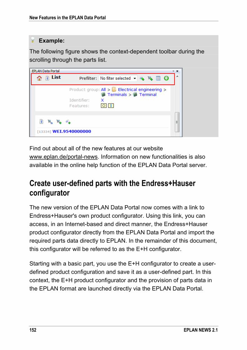
New Features in the EPLAN Data Portal
152 EPLAN NEWS 2.1
Example:
The following figure shows the context-dependent toolbar during the
scrolling through the parts list.
Find out about all of the new features at our website
www.eplan.de/portal-news. Information on new functionalities is also
available in the online help function of the EPLAN Data Portal server.
Create user-defined parts with the Endress+Hauser configurator
The new version of the EPLAN Data Portal now comes with a link to
Endress+Hauser's own product configurator. Using this link, you can
access, in an Internet-based and direct manner, the Endress+Hauser
product configurator directly from the EPLAN Data Portal and import the
required parts data directly to EPLAN. In the remainder of this document,
this configurator will be referred to as the E+H configurator.
Starting with a basic part, you use the E+H configurator to create a user-
defined product configuration and save it as a user-defined part. In this
context, the E+H product configurator and the provision of parts data in
the EPLAN format are launched directly via the EPLAN Data Portal.
New Features in the EPLAN Data Portal
EPLAN NEWS 2.1 153
You start the E+H configurator, for example, by clicking the button
in the block view of the parts list for a part of Endress+Hauser. This will
open in the EPLAN Data Portal an Internet page of Endress+Hauser with
the configurator.
Make the required settings for the selected part in the E+H configurator.
This fills the field next to the shopping cart symbol and generates an
order number. Click the shopping cart symbol to check and save the
configuration created.
If your information was complete, the E+H configurator will close, and a
user-defined part will be generated in the EPLAN Data Portal. You can
import this part, like all other parts, too, into the EPLAN platform-specific
parts management, or import it as a device in the graphical editor.
List with user-defined parts
All user-defined parts are gathered in a separate parts list. To display
this list, in the top toolbar click the button. The parts collected in the
User-defined parts list can be imported or deleted all at once via corres-
ponding buttons.
The button and the User-defined parts list are only available if user-
defined parts have been generated by means of the E+H configurator.
User-defined parts are stored in the EPLAN Data Portal only for a short
amount of time and then deleted.
Create user-defined parts directly
If you know the order number of a configured part, you can use it to start
the E+H configurator with predefined settings.
To do so, in the catalog or parts list you select the parts of Endress+
Hauser and then click the button next to the Prefilter field in the
toolbar. Enter the order number of the relevant part in the dialog that
opens then, and click the [Submit] button.

New Features in the EPLAN Data Portal
154 EPLAN NEWS 2.1
This will open the E+H configurator with the corresponding default set-
tings. By clicking the shopping cart symbol, you generate a user-defined
part in the EPLAN Data Portal.
By modifying an existing configuration, for example, you can create
several user-defined parts quickly.
Start the Rittal Therm configurator
The new EPLAN Data Portal version comes with a link to the current
Rittal Therm configurator in version 6.1. This program of Rittal imports
the calculation and design of the individual heating, cooling, and air-con-
ditioning solutions for enclosures and housings. Using the configurator,
you can determine the required components in Rittal Therm, fabricate
them into an comprehensive solution, and transfer them via the shopping
cart of the EPLAN Data Portal.
Note:
In order to start the Rittal Therm configurator from the EPLAN
Data Portal, you must first register with Rittal Therm (e.g., at
http://www.rittal.com/registration). Here you will obtain the required
data to log onto the configurator.
Before launching the Rittal Therm configurator, you can enter the lan-
guage of the configurator and your login data for Rittal Therm in the
Settings dialog. This eliminates the need for language selection and
logon for Rittal Therm, which you would normally have to do at the initial
launch of the Rittal Therm configurator.
To start the Rittal Therm configurator, select the manufacturer Rittal and
then click the button next to the Prefilter field in the toolbar.

New Features in the EPLAN Data Portal
EPLAN NEWS 2.1 155
In Rittal Therm 6.1, the design of the enclosure air-conditioning is rea-
lized within projects. In a project, you enter the relevant data (power
dissipation, max. external and internal temperature, etc.) for a selected
enclosure housing to start the calculation. After the calculation and deter-
mination of the required cooling devices, you can import the required
parts into the EPLAN Data Portal.
To do so, click the button in the summary of a project.
The main and accessory parts determined are carried over to the EPLAN
Data Portal shopping cart. If there are already parts in the shopping cart,
a prompt will open with which to decide on emptying the shopping cart
first.
Using a new shopping cart function, you can then import these parts into
the EPLAN device list, and from there place them as devices in an
opened layout space.
Import parts from the shopping cart into the device list
The shopping cart toolbar now comes with the new button. Using this
button, you can import parts that are contained in the shopping cart into
the EPLAN platform-specific device list.
This way, you can fill the EPLAN platform device list with parts taken
from the EPLAN Data Portal. From within the device list, you can then
place the parts as devices in the schematic / 3D layout space.
This requires the following:
The parts are available in parts management. (For this purpose, you
may have to import these parts first into parts management.)
The parts contain a macro or width, height, and depth information for
the simplified representation in the 3D layout space.
New Features in the EPLAN Data Portal
156 EPLAN NEWS 2.1
Insert a specific macro variant
If a macro stored for a part in the EPLAN Data Portal comes with differ-
ent variants, you can now select a specific macro variant for placement
in the graphical editor.
For this purpose, click the macro preview screen in the detail view of a
part and thus open the macro detail view. Here, click the button next to
the Variants of macro <Macro name> field. This will list the variants
below the macro detail view. To insert a special variant, click the but-
ton directly above the respective variant designation. The macro variant
then hangs on the mouse pointer and can be placed in the graphical
editor.

New features in the "EPLAN API Extension" add-on
EPLAN NEWS 2.1 157
New features in the "EPLAN API Extension" add-on
Note:
The "EPLAN API Extension" add-on is available as an option as part of
our EPLAN API Developer Network (EADN) as a developer's package
for the program variants EPLAN Electric P8 Professional. EPLAN Fluid,
and EPLAN PPE.
A unified, and especially high-performance, programming interface (API,
Application Programming Interface) is available for EPLAN platform pro-
ducts. This add-on – the EPLAN API – allows you to develop your own
customized solutions in collaboration with EPLAN or other partners. For
more information on EPLAN API and EADN, visit the EPLAN webpages
under the heading "Services > EPLAN API Developer Network".
The following sections provide information on the various new features
of the EPLAN API. To use the new EPLAN API version to develop your
own applications, you will require the Microsoft .NET Framework 4.0.
Start the program via command line parameters
As a result of the modified installation behavior, now several program
features are installed with program files (see section "Installation using
the EPLAN Setup Manager" on page 177). The program can still be launched by means of command line parameters via the file W3u.exe
of your installed EPLAN program variant.
Example:
For an installation of EPLAN Electric P8 under the Windows 7 (64-bit version) operating system, the file path for this file is: "C:\Program
Files (x86)\EPLAN\Electric P8\2.1.4\BIN\W3u.exe".

New features in the "EPLAN API Extension" add-on
158 EPLAN NEWS 2.1
Other new features in the EPLAN API
Store missing parts in a project
In the new EPLAN API, it is now also possible to store missing parts in a project. For this purpose, the PartsFromSystemToProject method has
been enhanced with an additional StoreMode parameter in the
Synchronize class.
Zip projects via the "backup" action
To allow you to zip projects now also with the backup action, the
BACKUPMETHOD parameter has been extended to include the PACK mode.
A command line call for this mode could look like this, for example: W3u.exe backup /TYPE:PROJECT /PROJECTNAME:"C:\Users\Public
\EPLAN\Electric P8\Projects\Company code\EPLAN-DEMO.elk"
/BACKUPMETHOD:PACK /BACKUPMEDIA:DISK.
EPLAN API templates for Visual Studio 2010
EPLAN API templates can now also be used in Microsoft Visual Studio
2010 and Visual Studio 2010 Express. These templates will facilitate, for
example, the creation of add-ins and offline programs.
Convert texts to path function texts
To convert text objects to path function texts, you can use the new ToPathText method in the PathText class. To convert path function
texts to texts, you can use the new ToText method from the PathText
class.
New methods for reports
In this version, the ReportBlock class of the EPLAN API has been
extended to include two new methods. Using the Delete method, you
can delete report blocks. You can freeze report pages with the Freeze
method. You will find the corresponding popup menu items in the
Reports dialog of the user interface.
New features in the "EPLAN API Extension" add-on
EPLAN NEWS 2.1 159
Define the number of connection points
In the EPLAN API, it is now also possible to define the number of
connection points for terminals with a variable number of connection points. The new Pins property has been added to the Function class
for this purpose.
Track nets
The new TrackNet method can now be found in the
ConnectionService class. This method allows you to use the
EPLAN API to determine all connections that belong to the same net.
Select all elements below a node
Using the new SelectionRecursive property in the SelectionSet
class, you can select all elements below a specific node within a navi-
gator dialog.
Rotate placed objects
In order to allow you to rotate objects placed on a page by a set angle using the EPLAN API, the Edit class now comes with the new Rotate
method.
Information on available licenses
To call up information on available licenses, use the new GetLicenseModules method in the License class in the
Eplan.EplApi.ApplicationFramework namespace. This will output
the licenses in the same manner in which they are displayed in the
Licensed add-ons tab of the user interface.
Determine element group
Using the new Group property in the Placement class, you can query
the element group to which an element belongs that has been placed in
the graphical editor, and possibly may have been grouped.

New features in the "EPLAN API Extension" add-on
160 EPLAN NEWS 2.1
Import STEP files
The Eplan.EplApi.HEServices namespace of the EPLAN API has
been extended for the import of 3D graphical data in the STEP format. The new Graphics3D method has been added to the Import class for
this import.
Select several parts in part selection
When selecting parts in the Part selection dialog using the ShowPartSelectionDialog method, you can now also select several
parts. This method belongs to the EplApplication class.
New object for model views
With the new ViewPart object from the Eplan.EplApi.DataModel
namespace, you can now access the properties of model views.
New methods to edit schemes
The SchemeSetting class has been extended to include several new
methods for editing schemes. This allows in the EPLAN API for the same
actions (create, copy, delete, etc. schemes) that are also available in the
user interface.
Sorting Terminals
The new SortTerminalStrips method can now be found in the
DeviceService class in the EPLAN API. This method allows you to sort
the terminals of a terminal strip automatically according to specific
criteria (numeric, page-based, etc.).

New features in the "EPLAN API Extension" add-on
EPLAN NEWS 2.1 161
Output labeling for selected objects
The EPLAN API now makes it possible to output the labeling for selected objects. The label action has been extended to include the
/USESELECTION parameter for this purpose. This parameter indicates
whether the current selection in the user interface is to be taken into
account in connection with the output of the labeling (optional, 0 = No, 1 = Yes; default value: 0). In addition, in the Label class, the DoLabel
method has been enhanced. This allows you to output specifically in the
labeling specific objects that you yourself transfer.
Create device groups
You can now group devices into a device group thanks to the EPLAN API. For this purpose, the new DeviceGroup class has been added to
the Eplan.EplApi.DataModel namespace.
Synchronize functions displayed in a distributed manner
To synchronize functions displayed in a distributed manner, you can use the PIDToOtherPlacementTypes method in the Synchronize class.
Using this method, you can transfer the properties of the P&I diagram
function for all representation types. In the user interface, this corres-
ponds to the menu path: Utilities > Synchronize > Functions > P&I
diagram --> all representation types.
To synchronize connections, the EPLAN API provides the following
methods:
MultilineToAllConnectionTypes
(corresponds in the Synchronize menu item to the submenu items:
Connections > Multi-line --> all representation types)
PanelLayout3DToAllConnectionTypes
(corresponds in the Synchronize menu item to the submenu items:
Connections > 3D mounting layout --> all representation types).

New features in the master data
162 EPLAN NEWS 2.1
New features in the master data
Master data: Symbols
Note:
The following pages show a number of illustrations of new symbols from
different symbol libraries. The illustrations show variant "A" of the respec-
tive symbols in multi-line representation. The name and number of the
symbol are shown underneath the symbol.
IEC, GOST, and GB standards
The following new symbols are available in the symbol libraries IEC_symbol, IEC_single_symbol, GOST_symbol,
GOST_single_symbol, GB_symbol and GB_single_symbol:
O_SP // 1263 XBS_SK // 1383
The following 77 new symbols have been added to the IEC_ED_ESS
symbol library:
TA_GS_08 // 8 BE_GS_36 // 36 BE_GS_35_1 // 37 BE_GS_35_2 // 38

New features in the master data
EPLAN NEWS 2.1 163
PG_ZUB_10 // 100 PG_ZUB_11 // 101 ALLG_03 // 140 NP_1 // 170
TA_ZUB_05_1
// 201
TA_ZUB_05_2
// 202
TA_ZUB_05_3
// 203
TA_ZUB_05_4
// 204
TA_ZUB_06_1
// 211
TA_ZUB_06_2
// 212
TA_ZUB_06_3
// 213
TA_ZUB_06_4
// 214
TA_ZUB_07_1
// 221
TA_ZUB_07_2
// 222
TA_ZUB_07_3
// 223
TA_ZUB_07_4
// 224
TA_ZUB_08_1
// 231
TA_ZUB_08_2
// 232
TA_ZUB_08_3
// 233
TA_ZUB_08_4
// 234
TA_ZUB_09_1
// 241
TA_ZUB_09_2
// 242
TA_ZUB_09_3
// 243
TA_ZUB_09_4
// 244
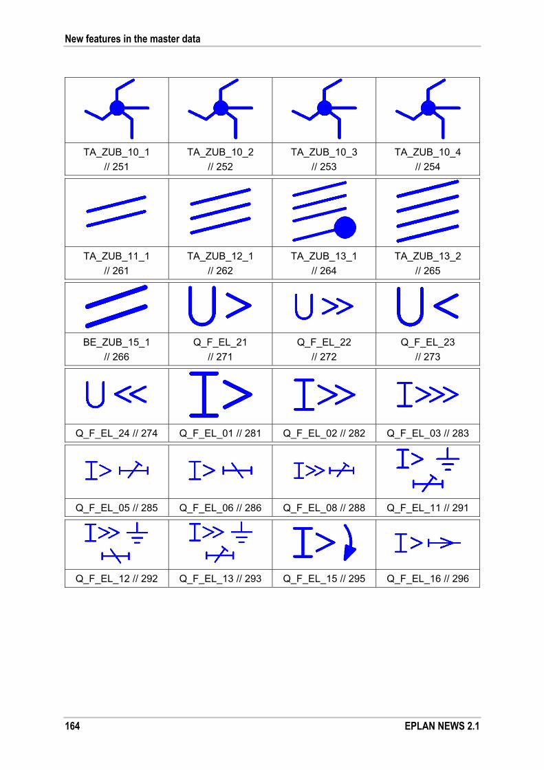
New features in the master data
164 EPLAN NEWS 2.1
TA_ZUB_10_1
// 251
TA_ZUB_10_2
// 252
TA_ZUB_10_3
// 253
TA_ZUB_10_4
// 254
TA_ZUB_11_1
// 261
TA_ZUB_12_1
// 262
TA_ZUB_13_1
// 264
TA_ZUB_13_2
// 265
BE_ZUB_15_1
// 266
Q_F_EL_21
// 271
Q_F_EL_22
// 272
Q_F_EL_23
// 273
Q_F_EL_24 // 274 Q_F_EL_01 // 281 Q_F_EL_02 // 282 Q_F_EL_03 // 283
Q_F_EL_05 // 285 Q_F_EL_06 // 286 Q_F_EL_08 // 288 Q_F_EL_11 // 291
Q_F_EL_12 // 292 Q_F_EL_13 // 293 Q_F_EL_15 // 295 Q_F_EL_16 // 296
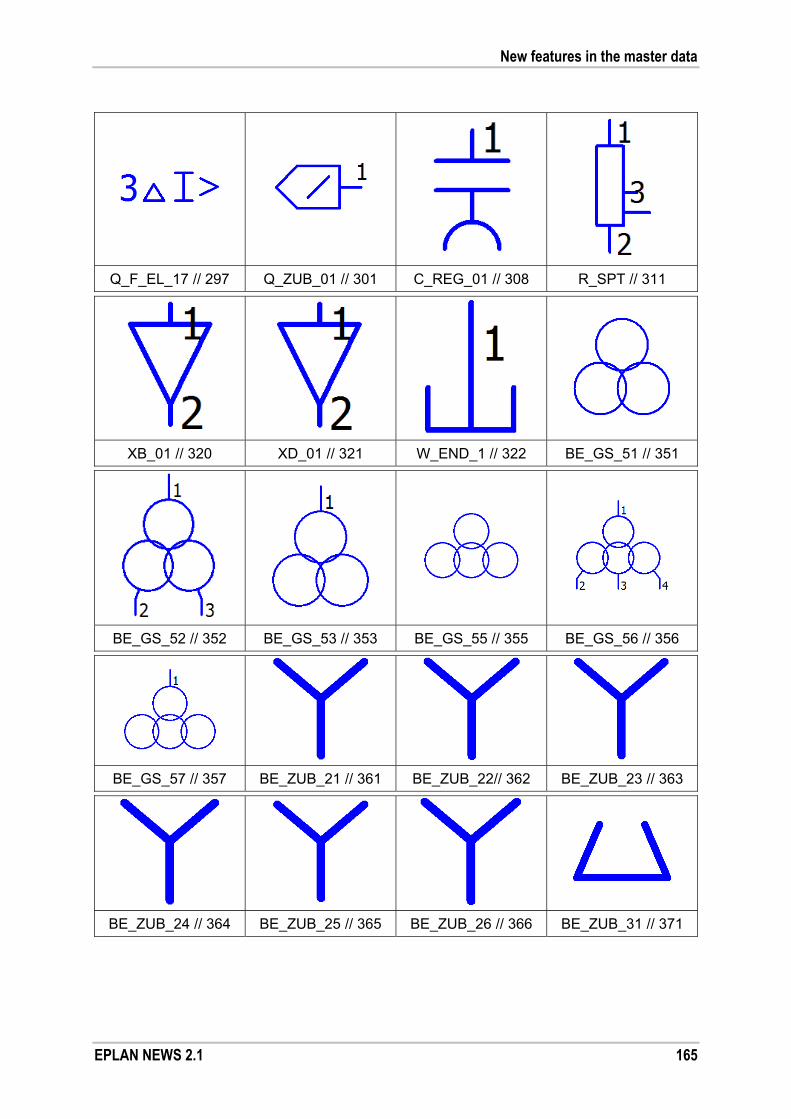
New features in the master data
EPLAN NEWS 2.1 165
Q_F_EL_17 // 297 Q_ZUB_01 // 301 C_REG_01 // 308 R_SPT // 311
XB_01 // 320 XD_01 // 321 W_END_1 // 322 BE_GS_51 // 351
BE_GS_52 // 352 BE_GS_53 // 353 BE_GS_55 // 355 BE_GS_56 // 356
BE_GS_57 // 357 BE_ZUB_21 // 361 BE_ZUB_22// 362 BE_ZUB_23 // 363
BE_ZUB_24 // 364 BE_ZUB_25 // 365 BE_ZUB_26 // 366 BE_ZUB_31 // 371

New features in the master data
166 EPLAN NEWS 2.1
BE_ZUB_32 // 372 BE_ZUB_33 // 373 BE_ZUB_34 // 374 BE_ZUB_35 // 375
BE_ZUB_36 // 376
NFPA standard
The following new symbols are available in the symbol libraries NFPA_symbol and NFPA_single_symbol:
O_SP // 1263 XBS_SK // 1383
Fluid power and process engineering
The following new symbols have been added to the HYD1ESS and
HYD2ESS symbol libraries:
V11.5.1_22_41
// 669
GS7.5.1_03
// 769
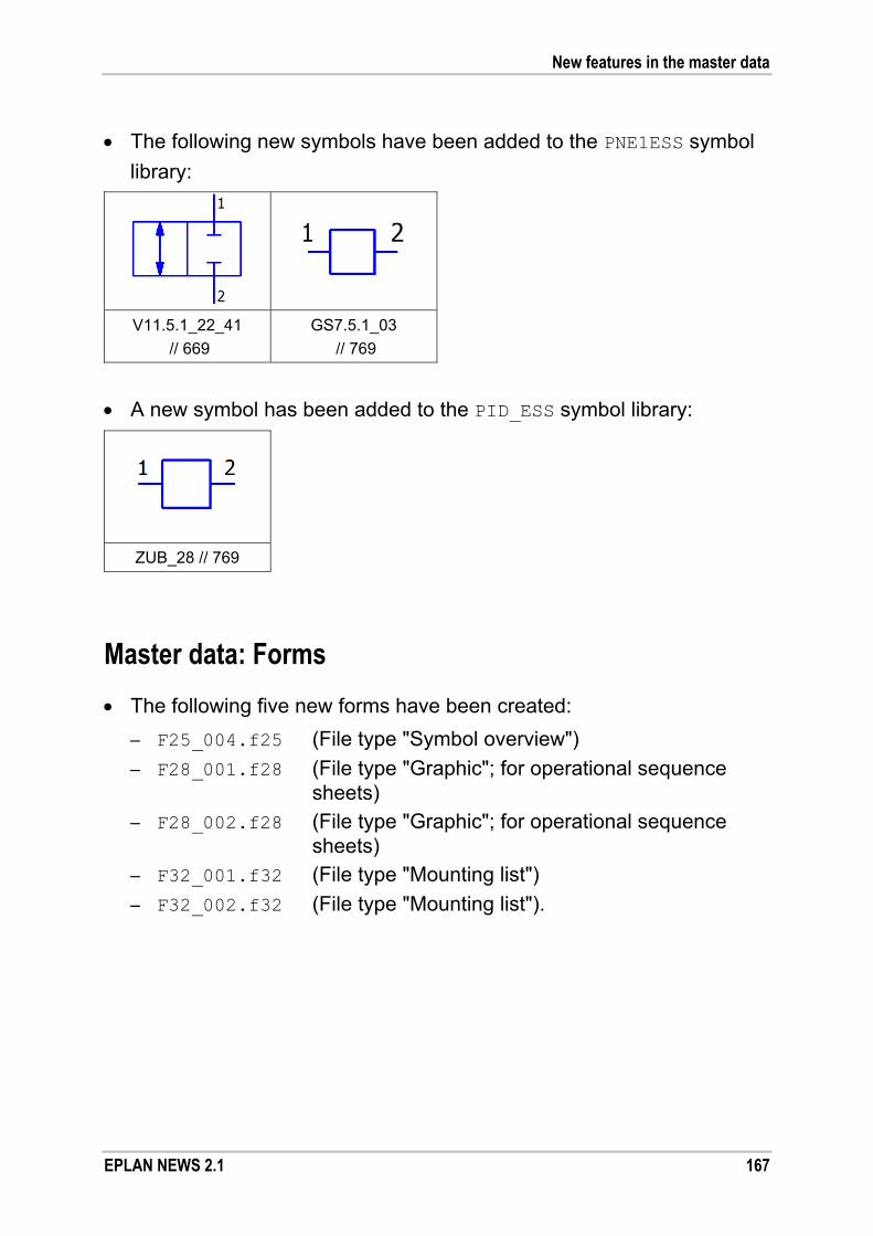
New features in the master data
EPLAN NEWS 2.1 167
The following new symbols have been added to the PNE1ESS symbol
library:
V11.5.1_22_41
// 669
GS7.5.1_03
// 769
A new symbol has been added to the PID_ESS symbol library:
ZUB_28 // 769
Master data: Forms
The following five new forms have been created:
– F25_004.f25 (File type "Symbol overview")
– F28_001.f28 (File type "Graphic"; for operational sequence sheets)
– F28_002.f28 (File type "Graphic"; for operational sequence sheets)
– F32_001.f32 (File type "Mounting list")
– F32_002.f32 (File type "Mounting list").
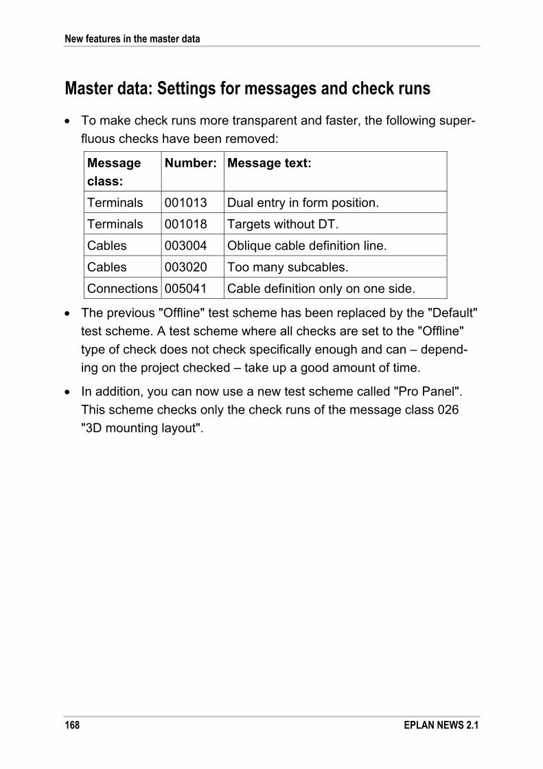
New features in the master data
168 EPLAN NEWS 2.1
Master data: Settings for messages and check runs
To make check runs more transparent and faster, the following super-
fluous checks have been removed:
Message
class:
Number: Message text:
Terminals 001013 Dual entry in form position.
Terminals 001018 Targets without DT.
Cables 003004 Oblique cable definition line.
Cables 003020 Too many subcables.
Connections 005041 Cable definition only on one side. The previous "Offline" test scheme has been replaced by the "Default"
test scheme. A test scheme where all checks are set to the "Offline"
type of check does not check specifically enough and can – depend-
ing on the project checked – take up a good amount of time.
In addition, you can now use a new test scheme called "Pro Panel".
This scheme checks only the check runs of the message class 026
"3D mounting layout".

New features in the master data
EPLAN NEWS 2.1 169
Master data: Macros
More than 20 new window macros have been created for the "EPLAN
Operational Sequence" add-on. These macros support you in creating
operational sequence sheets / GRAFCET diagrams. After the installa-tion, the macros are available from the OS_ESS macro subdirectory.
The following figures show the possible variants of a macro (where
available) from left to right in the sequence "Variant A - Variant H".
Action.ema
Action_connection.ema
Arrows.ema
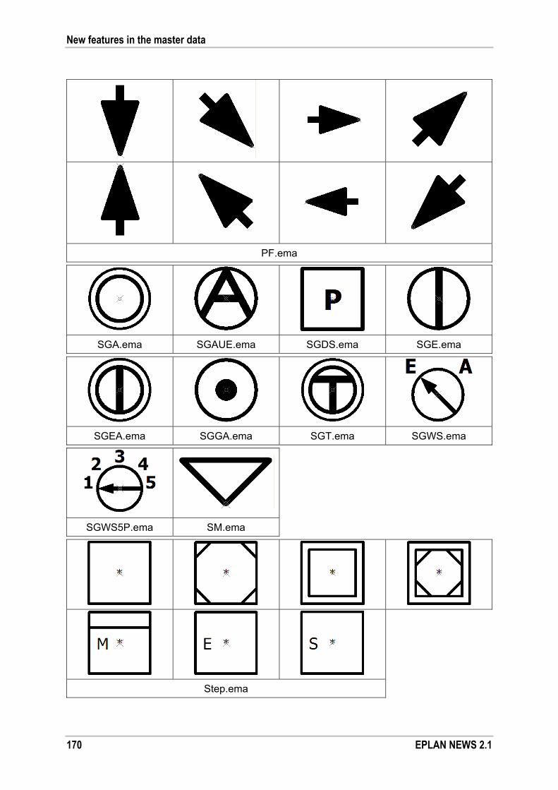
New features in the master data
170 EPLAN NEWS 2.1
PF.ema
SGA.ema SGAUE.ema SGDS.ema SGE.ema
SGEA.ema SGGA.ema SGT.ema SGWS.ema
SGWS5P.ema SM.ema
Step.ema

New features in the master data
EPLAN NEWS 2.1 171
Step_Transition.ema
Transition.ema
ZG.ema

Other new features and information
172 EPLAN NEWS 2.1
Other new features and information
Customer queries and messages
Note:
Please note that the following EPLAN service is not possible in all
countries.
A large number of your queries and wishes have contributed to the new
version of the EPLAN platform. Please note that not all subjects can be
listed within the scope of this document. You can, however, query the
status of your message ("issue") with us at any time.
Login to EPLAN Support on the Internet (software service customers
only) and, within our support area, click the Login Call-Tracking hyperlink
under Call tracking. The "EPLAN Support Call Tracking" page will now
open in your browser.

Other new features and information
EPLAN NEWS 2.1 173
You need the following information to log on here:
User name (= your last name)
The first five digits of your Software service number.
After filling out the form, confirm this information by clicking [Login].
In the Issue No. field on the next page, enter the issue number that you
were given by support and click [Search].

Other new features and information
174 EPLAN NEWS 2.1
You will be redirected to your message. This will show you an overview
of your support query.

Other new features and information
EPLAN NEWS 2.1 175
Validation code
To use this new version of EPLAN, you need a new validation code. This
is provided on the delivery note sent with your storage medium. In addi-
tion, you have the option of retrieving the validation code via the internet
(see the following section).
Retrieving the validation code online
EPLAN enables you to carry out the final installation step quickly and
easily by allowing you to retrieve the validation code required for licens-
ing via the internet. After the required data have been transmitted, the
validation code is automatically copied into the license dialog.
Note:
Please note that you must be connected to the internet to download
the validation code. You cannot retrieve a validation code for network
licenses or licenses without a dongle.
The Enter validation code dialog has been enhanced to allow you the
option of retrieving the validation code online.
This dialog, for example, opens when you start the application for the
first time after an installation. Click the new [Retrieve online] button.
The Company name and Serial number are automatically entered into
the open Set validation code online dialog. This data is needed to re-
trieve the validation code successfully.

Other new features and information
176 EPLAN NEWS 2.1
Up-to-date information
If you would like to receive information in the future (such as our eNews-
letter), please select the I would like to receive further information
check box. EPLAN will then save your personal details (Name, Phone,
E-mail address, etc.).
Internet settings
The settings for the existing internet connection are adopted by default.
You can also use a proxy server as a network component via the
[Settings] button and the dialog that then opens. If this is the case, you
must enter the corresponding information on Address, Port, etc. Please
consult with your administrator about the settings in this area.
Returning the validation code
Click [Send] to send the encoded data to EPLAN. If your details are
already held by EPLAN and are valid, a validation code is created and
sent to the license dialog. Then start the application by clicking [OK].

Other new features and information
EPLAN NEWS 2.1 177
Installation
Installation using the EPLAN Setup Manager
EPLAN program variants and add-ons are now installed using the new
EPLAN Setup Manager.
Improved ergonomics and a user-friendly user interface will assist you in
the installation. The EPLAN Setup Manager displays all basic information
on the individual installation steps in the dialog window. If necessary, you
can start a detail view and modify the default settings.
Other new features and information
178 EPLAN NEWS 2.1
Even though this installation program is significantly different from the
previous installation wizard in "look and feel", most of the settings will be
familiar to you (e.g., the definition of the target directories).
Division in installation bundles
Another new feature in the EPLAN Setup Manager is the division of pro-
gram features and the data to be installed (master data, language mod-
ules, etc.) into several installation bundles.
Thus, there is now a common installation bundle for the program core of
all program variants – the program files of the EPLAN platform. The files (e.g., W3u.exe) are installed in a new shared program directory with the
designation Platform. With the Windows Vista and Windows 7 operat-
ing systems, the default directory is:
\Program Files\EPLAN\Platform (32-bit version)
\Program Files (x86)\EPLAN\Platform (64-bit version).
In Windows XP, the default directory is \Program Files\EPLAN\
Platform.
Benefit: The division in several installation bundles allows for the
specific updating of program files. Given the well-defined
data size of such a bundle, possible corrections or the data
of a Hotfix, for example, can be downloaded quickly and
easily from the Internet (patch method).
Since the EPLAN program variants use the program files of
the EPLAN platform, computers on which several EPLAN
products are installed require less memory. A downloaded
patch for the EPLAN platform is then effective for all EPLAN
program variants installed.

Other new features and information
EPLAN NEWS 2.1 179
In addition, for each program variant, for each add-on, for the EPLAN
License Client, as well as for the master data, there are separate instal-
lation bundles.
Customized installation
You will notice that when you opt for the customized installation and click
the [Customized installation] button in the relevant installation dialog.
Subsequently, the table Program features is revealed.
For example, if you install EPLAN Electric P8 – as shown in the figure –
the following five installation bundles will be displayed as program
features:
EPLAN License Client:
installation bundle for licensing.
EPLAN Electric P8 2.1:
installation bundle for the program files of the program variant.

Other new features and information
180 EPLAN NEWS 2.1
EPLAN Electric P8 Addon 2.1:
installation bundle for the original EPLAN master data of the program
variant.
EPLAN Shared 2.1:
installation bundle for the program files of the EPLAN platform.
EPLAN Shared 2.1:
installation bundle for non-project-specific original EPLAN master data
of the EPLAN platform.
Note:
Please note that the installation bundles are all installed, together with
the program files, in the same program directory. So when you install a
further EPLAN program variant, you must also select this program direc-
tory.
Here, and this is yet another innovation, additional information such as
the version number or status of a program feature is displayed. This way,
you can see, for example, which program features have already been
installed. Features that may have been forgotten in an earlier installation
can now be installed.
The program files of an EPLAN program variant are still installed in
a separate program directory. Thus, the files for EPLAN Electric P8 (e.g., install.xml) are stored below the following directory by default
when using the Windows Vista and Windows 7 operating systems:
\Program Files\EPLAN\Electric P8 (32-bit version)
\Program Files (x86)\EPLAN\Electric P8 (64-bit version).
For the Windows XP operating system, the files are stored below the following directory by default: \Program Files\EPLAN\Electric P8.
Other new features and information
EPLAN NEWS 2.1 181
Master data and languages
In order to select the master data as well as the interface and online-help
languages, click the [Master data and languages] button. You can then
make your selection in the expanded tables Master data types, Lan-
guage modules and Help system languages.
The language displayed in the Activated field is the language that is
preset as the interface language / help system language at the initial
start of the respective program variant. If you have activated the check
boxes for several languages in the Language modules and Help sys-
tem languages tables, you can select one of these languages as the
"start language" in the respective Activated drop-down list.
Start installation
If by clicking the respective check box you have deactivated an abso-
lutely necessary program feature for the installation, the EPLAN Setup
Manager will display a corresponding message. This will prevent an
incomplete installation.
Click the [Install] button to start the installation. After the installation has
been completed, exit the EPLAN Setup Manager by clicking the [Finish]
button.
Notes:
The master data are installed using the add-on method. For this
reason, the corresponding installation bundles in the EPLAN Setup
Manager are also called "Addon".
In the respective installed EPLAN program variant, therefore, the
master data are displayed also as registered add-ons in the Add-ons
dialog. Also during the synchronization of master data in the Master
data synchronization - system master data dialog, the master data
are listed in the Source field as add-ons.

Other new features and information
182 EPLAN NEWS 2.1
Uninstalling
If, for example, you double-click the entry "EPLAN Electric P8 2.1" in the
respective uninstall dialog of the control panel, the EPLAN Setup Manag-
er is also launched.
Using the EPLAN Setup Manager, you can uninstall all EPLAN program
components collectively or individually. Select the program components
to be removed and click [Remove].
Program features that do not represent a program variant (e.g., "EPLAN
Platform 2.1" or "EPLAN Electric P8 Addon") are displayed in the Control
Panel, but cannot be uninstalled individually. The [Remove] button or
the Uninstall menu item will not be available for the respective entry in
the Control Panel.

Other new features and information
EPLAN NEWS 2.1 183
Software requirements and approvals
All release information refers to the 32-bit version of the products, unless
stated otherwise.
General requirements
The Microsoft .NET framework 4.0 is required to operate the EPLAN
platform. Further information and the latest version of .NET framework
are available for download from the Microsoft website.
You will find .NET Framework 4.0 on your EPLAN storage medium.
Switch to the following directory:
cd-rom\Services\Net Framework 4.0\en_US
To install .NET Framework, double-click the file DotNetFx40_Full_x86_x64.exe.
Operating systems
EPLAN recommends that a 64 bit Windows operating system is used.
The EPLAN platform has been cleared for the following operating sys-
tems:
Workstation
Microsoft Windows XP Professional SP3 (32 bit)
Microsoft Windows Vista SP2 (32 bit and 64 bit)
Enterprise, Business N, Ultimate
Microsoft Windows 7 SP1 (32 bit and 64 bit)
Professional, Enterprise, Ultimate
Server
Microsoft Windows Server 2003 SP2 (32 bit and 64 bit)
Microsoft Windows Server 2008 SP2 (32 bit and 64 bit)
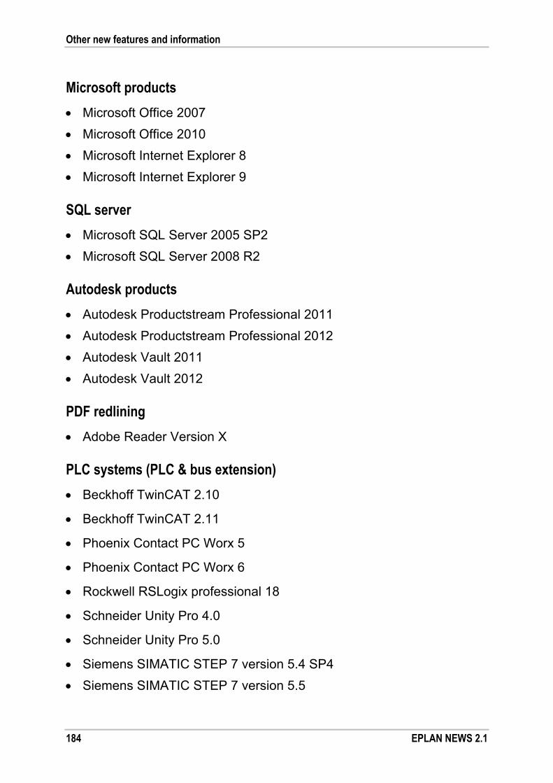
Other new features and information
184 EPLAN NEWS 2.1
Microsoft products
Microsoft Office 2007
Microsoft Office 2010
Microsoft Internet Explorer 8
Microsoft Internet Explorer 9
SQL server
Microsoft SQL Server 2005 SP2
Microsoft SQL Server 2008 R2
Autodesk products
Autodesk Productstream Professional 2011
Autodesk Productstream Professional 2012
Autodesk Vault 2011
Autodesk Vault 2012
PDF redlining
Adobe Reader Version X
PLC systems (PLC & bus extension)
Beckhoff TwinCAT 2.10
Beckhoff TwinCAT 2.11
Phoenix Contact PC Worx 5
Phoenix Contact PC Worx 6
Rockwell RSLogix professional 18
Schneider Unity Pro 4.0
Schneider Unity Pro 5.0
Siemens SIMATIC STEP 7 version 5.4 SP4
Siemens SIMATIC STEP 7 version 5.5

Other new features and information
EPLAN NEWS 2.1 185
Unsupported operating systems
Windows 2000 Professional
The EPLAN platform no longer supports the Windows 2000 Professional
operating system that is no longer supported by Microsoft.
Windows 2000 Server
The EPLAN platform no longer supports the Windows 2000 Server oper-
ating system that is no longer supported by Microsoft. Microsoft has
ceased official support for this operating system.
Note:
Further information on the life cycle of operating systems is available on
the Microsoft website.
Other software that is no longer supported
Interface cards for parallel dongles
Starting with Version 2.0 SP 1, the EPLAN platform comes with a new
dongle driver. Because of the enhanced technology in the new Microsoft
operating systems (Windows 7 and Windows Server 2008), this dongle
driver no longer supports interface cards (PCI cards). For this reason,
interface cards for parallel dongles are no longer supported by the cur-
rent version of the EPLAN platform.

Other new features and information
186 EPLAN NEWS 2.1
Hardware requirements
Workstation hardware requirements
The computer platform is a PC with an Intel Pentium 4 or compatible
processor.
If you are using a processor that dates to before 2005, check whether
this processor supports SSE2 command sets. The "CPU-Z" program
allows you to do this. This program can be downloaded free of charge
from http://www.cpuid.com/.
The introduction of the enhanced command set SSE2 (Streaming SIMD
Extensions 2) started with the Intel Pentium 4 in 2001. In the case of
AMD processors, this enhancement was introduced with the Athlon 64
in 2005. If you use a computer system from Intel, the CPU should have
been manufactured after 2002. In the case of AMD processors, the CPU
should be newer than 2005.
Recommended workstation configuration
Processor: Comparable to an Intel Pentium D at 3 GHz or
comparable to an Intel Core 2 Duo at 2.4 GHz
RAM: 4 GB*1
Hard disk: 160 GB
Monitor / graphics
resolution:
2-screen solution 21" or 16:10 graphics system
with a resolution of 1680 x 1050
3D display: Graphics card from ATI or Nvidia with the latest
OpenGL driver *1: Individual functions like PDF or DXF output require more memory in connection
with projects or very extensive graphics.

Other new features and information
EPLAN NEWS 2.1 187
Minimum net requirements
As stated in the software requirements and performance, only operate
the server with a Microsoft Windows operating system.
Net transfer rate of the server: 1 Gbits/s
Net transfer rate of the client computer: 100 Mbits/s
Recommended latency: < 1 ms
Minimum multi-user requirements
With regard to minimum requirements for multi-user operation, please
contact EPLAN Support. We can advise you specifically according to
your individual requirements.

Other new features and information
188 EPLAN NEWS 2.1