new polarization switching method switching four ... · pdf filelines are shown in the...
TRANSCRIPT
6 The AMSAT Journal May/June 2007 www.amsat.org
New Polarization Switching MethodSwitching Four Polarizations on a 70 cm Crossed Yagi (Part 2)
by Domenico Marini, i8CVS, [email protected]
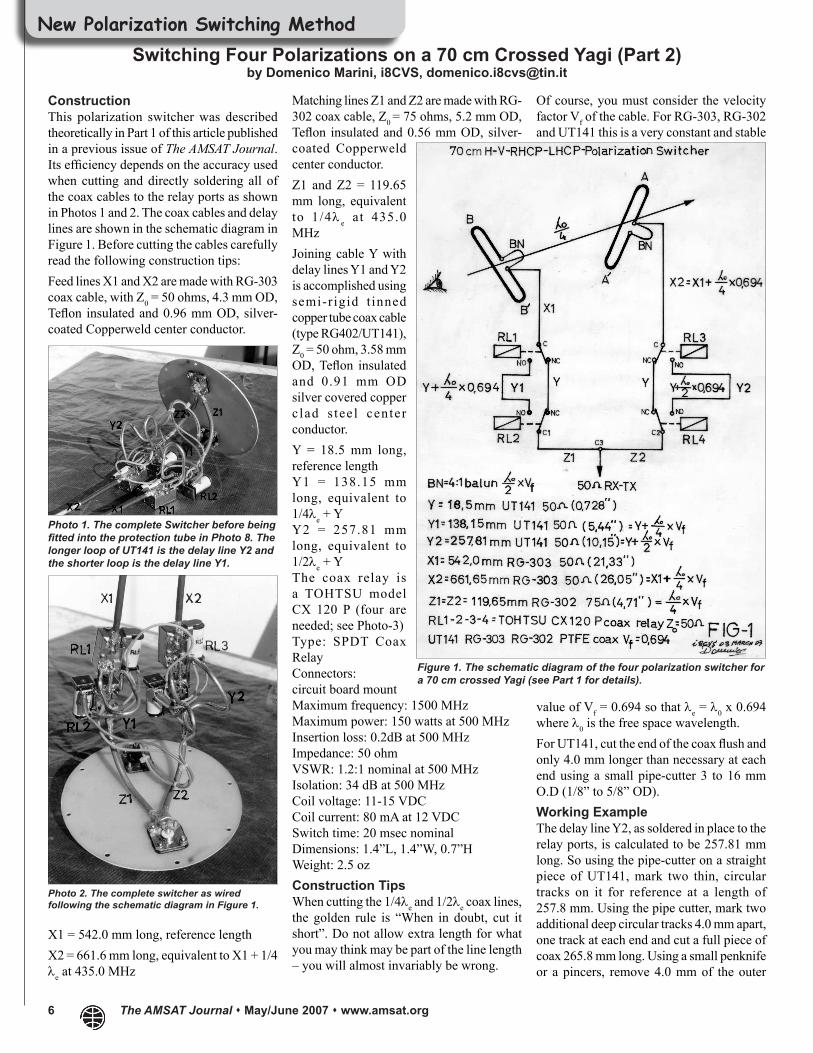
Matching lines Z1 and Z2 are made with RG-302 coax cable, Z0 = 75 ohms, 5.2 mm OD, Teflon insulated and 0.56 mm OD, silver-coated Copperweld center conductor.Z1 and Z2 = 119.65 mm long, equivalent to 1/4λ e at 435.0 MHzJoining cable Y with delay lines Y1 and Y2 is accomplished using semi-r igid t inned copper tube coax cable (type RG402/UT141), Z0 = 50 ohm, 3.58 mm OD, Teflon insulated and 0.91 mm OD silver covered copper c lad s tee l center conductor.Y = 18.5 mm long, reference lengthY1 = 138.15 mm long, equivalent to 1/4λe + YY2 = 257.81 mm long, equivalent to 1/2λe + YThe coax relay is a TOHTSU model CX 120 P (four are needed; see Photo-3)Type: SPDT Coax RelayConnectors:circuit board mountMaximum frequency: 1500 MHzMaximum power: 150 watts at 500 MHzInsertion loss: 0.2dB at 500 MHzImpedance: 50 ohmVSWR: 1.2:1 nominal at 500 MHzIsolation: 34 dB at 500 MHzCoil voltage: 11-15 VDCCoil current: 80 mA at 12 VDCSwitch time: 20 msec nominalDimensions: 1.4”L, 1.4”W, 0.7”HWeight: 2.5 ozConstruction TipsWhen cutting the 1/4λe and 1/2λe coax lines, the golden rule is “When in doubt, cut it short”. Do not allow extra length for what you may think may be part of the line length – you will almost invariably be wrong.
Of course, you must consider the velocity factor Vf of the cable. For RG-303, RG-302 and UT141 this is a very constant and stable
value of Vf = 0.694 so that λe = λ0 x 0.694 where λ0 is the free space wavelength.For UT141, cut the end of the coax flush and only 4.0 mm longer than necessary at each end using a small pipe-cutter 3 to 16 mm O.D (1/8” to 5/8” OD).Working ExampleThe delay line Y2, as soldered in place to the relay ports, is calculated to be 257.81 mm long. So using the pipe-cutter on a straight piece of UT141, mark two thin, circular tracks on it for reference at a length of 257.8 mm. Using the pipe cutter, mark two additional deep circular tracks 4.0 mm apart, one track at each end and cut a full piece of coax 265.8 mm long. Using a small penknife or a pincers, remove 4.0 mm of the outer
ConstructionThis polarization switcher was described theoretically in Part 1 of this article published in a previous issue of The AMSAT Journal. Its efficiency depends on the accuracy used when cutting and directly soldering all of the coax cables to the relay ports as shown in Photos 1 and 2. The coax cables and delay lines are shown in the schematic diagram in Figure 1. Before cutting the cables carefully read the following construction tips:Feed lines X1 and X2 are made with RG-303 coax cable, with Z0 = 50 ohms, 4.3 mm OD, Teflon insulated and 0.96 mm OD, silver-coated Copperweld center conductor.
X1 = 542.0 mm long, reference lengthX2 = 661.6 mm long, equivalent to X1 + 1/4 λe at 435.0 MHz
Photo 1. The complete Switcher before being fitted into the protection tube in Photo 8. The longer loop of UT141 is the delay line Y2 and the shorter loop is the delay line Y1.
Photo 2. The complete switcher as wired following the schematic diagram in Figure 1.
Figure 1. The schematic diagram of the four polarization switcher for a 70 cm crossed Yagi (see Part 1 for details).
The AMSAT Journal May/June 2007 www.amsat.org 7
copper tube at each end bending the outer tube up and down slowly over the previously made thin reference mark.Using a razor blade or an X-ACTO knife cut flush and remove 4 mm of Teflon insulating material from over the inner conductor at each end. Be careful to not cut too much toward the inner conductor or you will score it and it will break while bending it 90° to fit over the relay stud.Now, Y2 can be shaped by hand into any form needed. After soldering both 4 mm ends in place the effective length of Y2 will be very close to 257.8 mm because the additional length of both 4 mm inner conductors that are exposed beyond the shield conductors and the relay stud lengths both become part of the length of the line. (See Photo 4)
The feed lines X1 and X2 are made using RG-303 and they are respectively 542.0 mm and 661.65 mm long. By the way, X1 can be cut to any convenient length, but it is mandatory that X2 be 1/4λe electrical wavelength longer, e.g., 119.65 mm longer than X1.Focus your attention at the end of X1 and X2, which is connected to the driven elements and note that no coax connectors are used at the feed points on folded dipoles. This is shown in Photo 5. A solder stud for the inner conductor and a copper clamp for the braid are used as KLM did in the original cables.The best method to precisely make X2 longer by 119.65 mm than X1 is to cut two pieces of RG-303 both 662.0 mm long and create the same connection arrangement shown in Photo 5. Try to solder both studs and copper clamps as symmetrically as possible over the cables and then cut away exactly 119.65 mm of coax from the other end of X1.To solder coax cables correctly on the relay ports, a powerful soldering iron ranging from 100 to 150 watts is necessary to compensate for the drop of temperature due to relay metallic mass. The best flux cored solder wire to be used is the alloy 62Sn/36Pb/2Ag from Alpha Metals Inc.The coax relay has three posts originally designed to be fitted into the PCB for ground purposes and they must be completely pre-tinned, including the entire surface all around the point from which the posts exit the metal as shown in Photo 6.Soldering the relay body is possible because the metal is plated with a conductive metal similar to that used on SMA aluminum connectors. The finished surface is compatible with the usual soldering processes.Soldering a big metallic mass requires that the relay body be maintained at high temperature. This is why a big soldering iron of the type used to solder copper bars over DC motor collectors is necessary. By the way, the body of this coax relay can withstand soldering temperatures for several minutes since all contacts and moving parts inside of it are Teflon insulated.The best soldering procedure on the workbench is to grip the relay in a small vice. Keep it protected from the vice jaws using two pieces of wood. This will prevent heat loss in the vise. The wood will burn slightly while soldering. Don’t forget to remove the relay cover before gripping the delicate relay in the vice jaws. The braid of the outer
copper tube of the coax must be pre-tinned before being soldered in place.Do not scratch or remove the conductive coating from the relay body or apply the soldering iron to it.
Photo 3. The coax relays, RL1-2-3-4, are Tohtsu model CX 120 P as seen from their front cover.
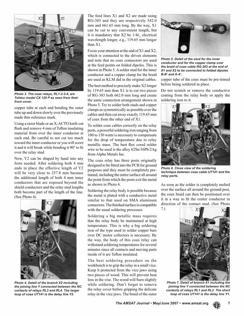
Photo 4. Detail of the branch X2 including the joining line Y connected between the NC contacts of relays RL3 and RL4. The larger loop of coax UT141 is the delay line Y2.
Photo 5. Detail of the stud for the inner conductor and for the copper clamp over the braid of coax cable RG-303 at the end of X1 and X2 to be connected to folded dipoles B-B’ and A-A’.
Photo 6. Close view of the soldering technique between coax cable UT141 and the relay ports.
As soon as the solder is completely melted over the surface all around the ground post, the coax braid can then be positioned over it in a way to fit the center conductor in direction of the contact stud. (See Photo 7.)
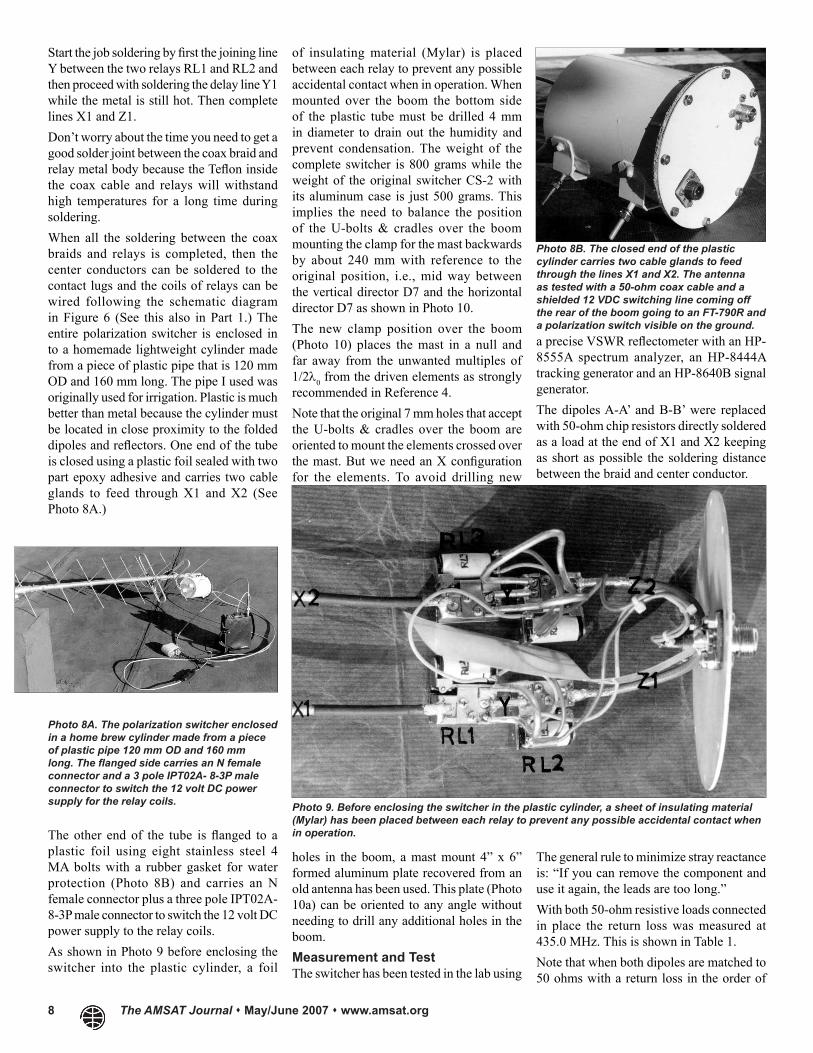
Photo 7. Detail of branch X1 including the joining line Y connected between the NC
contacts of relays RL1 and RL2. The short loop of coax UT141 is the delay line Y1.
8 The AMSAT Journal May/June 2007 www.amsat.org
Start the job soldering by first the joining line Y between the two relays RL1 and RL2 and then proceed with soldering the delay line Y1 while the metal is still hot. Then complete lines X1 and Z1.Don’t worry about the time you need to get a good solder joint between the coax braid and relay metal body because the Teflon inside the coax cable and relays will withstand high temperatures for a long time during soldering.When all the soldering between the coax braids and relays is completed, then the center conductors can be soldered to the contact lugs and the coils of relays can be wired following the schematic diagram in Figure 6 (See this also in Part 1.) The entire polarization switcher is enclosed in to a homemade lightweight cylinder made from a piece of plastic pipe that is 120 mm OD and 160 mm long. The pipe I used was originally used for irrigation. Plastic is much better than metal because the cylinder must be located in close proximity to the folded dipoles and reflectors. One end of the tube is closed using a plastic foil sealed with two part epoxy adhesive and carries two cable glands to feed through X1 and X2 (See Photo 8A.)
of insulating material (Mylar) is placed between each relay to prevent any possible accidental contact when in operation. When mounted over the boom the bottom side of the plastic tube must be drilled 4 mm in diameter to drain out the humidity and prevent condensation. The weight of the complete switcher is 800 grams while the weight of the original switcher CS-2 with its aluminum case is just 500 grams. This implies the need to balance the position of the U-bolts & cradles over the boom mounting the clamp for the mast backwards by about 240 mm with reference to the original position, i.e., mid way between the vertical director D7 and the horizontal director D7 as shown in Photo 10.The new clamp position over the boom (Photo 10) places the mast in a null and far away from the unwanted multiples of 1/2λ0 from the driven elements as strongly recommended in Reference 4.Note that the original 7 mm holes that accept the U-bolts & cradles over the boom are oriented to mount the elements crossed over the mast. But we need an X configuration for the elements. To avoid drilling new
a precise VSWR reflectometer with an HP-8555A spectrum analyzer, an HP-8444A tracking generator and an HP-8640B signal generator.The dipoles A-A’ and B-B’ were replaced with 50-ohm chip resistors directly soldered as a load at the end of X1 and X2 keeping as short as possible the soldering distance between the braid and center conductor.
Photo 8A. The polarization switcher enclosed in a home brew cylinder made from a piece of plastic pipe 120 mm OD and 160 mm long. The flanged side carries an N female connector and a 3 pole IPT02A- 8-3P male connector to switch the 12 volt DC power supply for the relay coils.
The other end of the tube is flanged to a plastic foil using eight stainless steel 4 MA bolts with a rubber gasket for water protection (Photo 8B) and carries an N female connector plus a three pole IPT02A- 8-3P male connector to switch the 12 volt DC power supply to the relay coils.As shown in Photo 9 before enclosing the switcher into the plastic cylinder, a foil
Photo 8B. The closed end of the plastic cylinder carries two cable glands to feed through the lines X1 and X2. The antenna as tested with a 50-ohm coax cable and a shielded 12 VDC switching line coming off the rear of the boom going to an FT-790R and a polarization switch visible on the ground.
Photo 9. Before enclosing the switcher in the plastic cylinder, a sheet of insulating material (Mylar) has been placed between each relay to prevent any possible accidental contact when in operation.
holes in the boom, a mast mount 4” x 6” formed aluminum plate recovered from an old antenna has been used. This plate (Photo 10a) can be oriented to any angle without needing to drill any additional holes in the boom.Measurement and TestThe switcher has been tested in the lab using
The general rule to minimize stray reactance is: “If you can remove the component and use it again, the leads are too long.”With both 50-ohm resistive loads connected in place the return loss was measured at 435.0 MHz. This is shown in Table 1.Note that when both dipoles are matched to 50 ohms with a return loss in the order of
The AMSAT Journal May/June 2007 www.amsat.org 9
20 to 25 db, the power feeding the switcher is divided in two equal parts as explained in Reference 3, Chapter 8, pages 8-10. The total switcher insertion loss under these conditions is 0.35 dB.
In addition, the antenna was tested using its original CS-2 switcher and the return loss while operating in RHCP was 23 dB (VSWR = 1.15) while operating in LHCP it was 25 dB (VSWR= 1.12).Finally the new switcher was mounted on the antenna and the measured VSWR is shown in Table 2.
Using the reference Yagis in TX mode for each polarization and the antenna under test in RX mode for each switched polarization, Table 3 shows the axial ratios in dB against a 0 dB reference level.Circularity TestThe antenna under test was switched to receive in circular polarization and the longitudinal axis of the boom was slowly rotated by 360° against a fixed linearly polarized 9 element Yagi transmitting in vertical or in horizontal polarization. A maximum change of 2 dB at 435.5 MHz was measured while receiving in each circular polarization RHCP or LHCP.Transmitting a RHCP reference signal and receiving with the same RHCP sense while axially rotating the antenna under test by 360° over the boom, less than +/-0.5 dB in signal strength was measured on spectrum analyzer set at 2 dB/div.The antenna was tested with a 50 ohm coax cable and a shielded 12 VDC switching line coming off the rear of the boom as in Photo 11 as recommended in the 435-40CX manual. A very small difference in VSWR was measured when these two cables were well laced together along the boom and coming off horizontally as they leave the mast mount aluminum plate visible in Photo-10 and run over to the support pole in a null position as recommended in Reference 4.By the way, since the antenna generates both a linear or a circular wavefront depending on polarization switching, it is better to run both cables off the rear of the boom whenever possible because no metallic object can be in close proximity without cutting this field and thereby disturbing the gain, VSWR, pattern and elipticity.Mounting the antenna in X configuration and following the recommendations in Reference 4 it is possible to get excellent results using a metallic support pole and running both cables along the boom.OperationBefore enclosing the switcher in the box the antenna was tested by receiving FO-29 from a balcony nearby the shack using a FT-817 without a preamplifier.In spite of the low sensitivity of 0.125 uV for 10 dB S/N corresponding to a noise figure NF = 5.14 dB, a very good signal was received from the CW beacon at 435.795 MHz. Thanks to IZ1ERR and IZ1DSJ a video was produced that is available at:
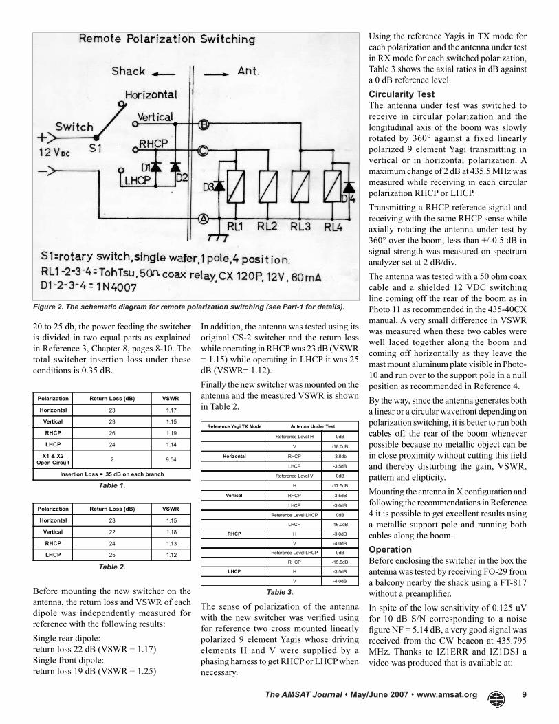
Figure 2. The schematic diagram for remote polarization switching (see Part-1 for details).
Polarization Return Loss (dB) VSWR
Horizontal 23 1.17
Vertical 23 1.15
RHCP 26 1.19
LHCP 24 1.14
X1 & X2Open Circuit 2 9.54
Insertion Loss = .35 dB on each branch
Table 1.
Before mounting the new switcher on the antenna, the return loss and VSWR of each dipole was independently measured for reference with the following results:Single rear dipole:return loss 22 dB (VSWR = 1.17)Single front dipole:return loss 19 dB (VSWR = 1.25)
Polarization Return Loss (dB) VSWR
Horizontal 23 1.15
Vertical 22 1.18
RHCP 24 1.13
LHCP 25 1.12
Table 2.
Reference Yagi TX Mode Antenna Under Test
Reference Level H 0dB
V -18.0dB
Horizontal RHCP -3.0db
LHCP -3.5dB
Reference Level V 0dB
H -17.5dB
Vertical RHCP -3.5dB
LHCP -3.0dB
Reference Level LHCP 0dB
LHCP -16.0dB
RHCP H -3.0dB
V -4.0dB
Reference Level LHCP 0dB
RHCP -15.5dB
LHCP H -3.5dB
V -4.0dB
Table 3.
The sense of polarization of the antenna with the new switcher was verified using for reference two cross mounted linearly polarized 9 element Yagis whose driving elements H and V were supplied by a phasing harness to get RHCP or LHCP when necessary.
10 The AMSAT Journal May/June 2007 www.amsat.org
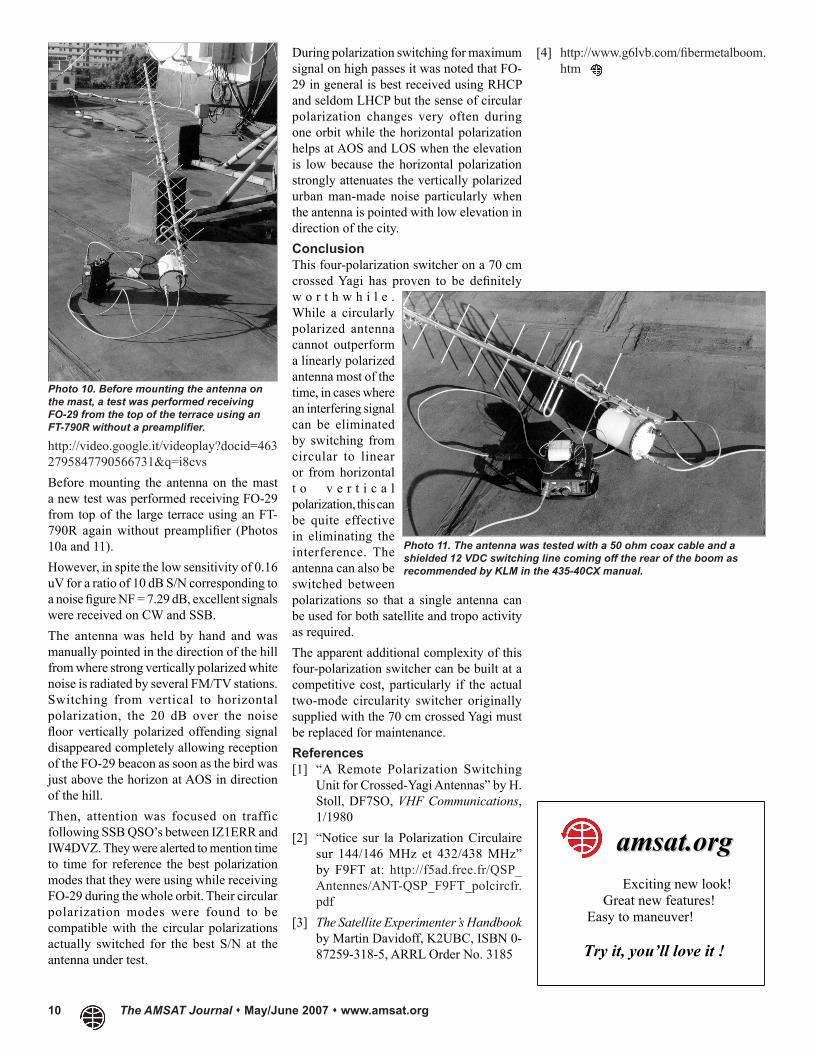
http://video.google.it/videoplay?docid=4632795847790566731&q=i8cvsBefore mounting the antenna on the mast a new test was performed receiving FO-29 from top of the large terrace using an FT-790R again without preamplifier (Photos 10a and 11).However, in spite the low sensitivity of 0.16 uV for a ratio of 10 dB S/N corresponding to a noise figure NF = 7.29 dB, excellent signals were received on CW and SSB.The antenna was held by hand and was manually pointed in the direction of the hill from where strong vertically polarized white noise is radiated by several FM/TV stations. Switching from vertical to horizontal polarization, the 20 dB over the noise floor vertically polarized offending signal disappeared completely allowing reception of the FO-29 beacon as soon as the bird was just above the horizon at AOS in direction of the hill.Then, attention was focused on traffic following SSB QSO’s between IZ1ERR and IW4DVZ. They were alerted to mention time to time for reference the best polarization modes that they were using while receiving FO-29 during the whole orbit. Their circular polarization modes were found to be compatible with the circular polarizations actually switched for the best S/N at the antenna under test.
During polarization switching for maximum signal on high passes it was noted that FO-29 in general is best received using RHCP and seldom LHCP but the sense of circular polarization changes very often during one orbit while the horizontal polarization helps at AOS and LOS when the elevation is low because the horizontal polarization strongly attenuates the vertically polarized urban man-made noise particularly when the antenna is pointed with low elevation in direction of the city.ConclusionThis four-polarization switcher on a 70 cm crossed Yagi has proven to be definitely w o r t h w h i l e . While a circularly polarized antenna cannot outperform a linearly polarized antenna most of the time, in cases where an interfering signal can be eliminated by switching from circular to linear or from horizontal t o v e r t i c a l polarization, this can be quite effective in eliminating the interference. The antenna can also be switched between polarizations so that a single antenna can be used for both satellite and tropo activity as required.The apparent additional complexity of this four-polarization switcher can be built at a competitive cost, particularly if the actual two-mode circularity switcher originally supplied with the 70 cm crossed Yagi must be replaced for maintenance.References[1] “A Remote Polarization Switching
Unit for Crossed-Yagi Antennas” by H. Stoll, DF7SO, VHF Communications, 1/1980
[2] “Notice sur la Polarization Circulaire sur 144/146 MHz et 432/438 MHz” by F9FT at: http://f5ad.free.fr/QSP_Antennes/ANT-QSP_F9FT_polcircfr.pdf
[3] The Satellite Experimenter’s Handbook by Martin Davidoff, K2UBC, ISBN 0-87259-318-5, ARRL Order No. 3185
Photo 10. Before mounting the antenna on the mast, a test was performed receiving FO-29 from the top of the terrace using an FT-790R without a preamplifier.
[4] http://www.g6lvb.com/fibermetalboom.htm
Photo 11. The antenna was tested with a 50 ohm coax cable and a shielded 12 VDC switching line coming off the rear of the boom as recommended by KLM in the 435-40CX manual.
Exciting new look! Great new features! Easy to maneuver!
Try it, you’ll love it !
aammssaatt..oorrgg