new gtg 2011 - clayton.edu
TRANSCRIPT
Page 1 Design Review Group
State of Georgia Telecommunications Guideline Georgia State Financing and Investment Commission
Telecommunications Guideline
March 31, 2011

Page 2 Design Review Group
State of Georgia Telecommunications Guideline Georgia State Financing and Investment Commission
Publication Designation
State of Georgia Telecommunications Guideline
Subject
Information Transport Systems, Telecommunications, Networking, Voice & Data,
A/V (Audio & Video), Energy Management, Lighting Controls, Security,
Fire/Safety, HVAC, Wireless Devices, and Intelligent Building Automation
Systems
Effective Date
March 31, 2011
Supersedes
State of Georgia Telecommunications Guidelines July 1, 2008
State of Georgia Telecommunications Design Manual, March 1, 2007
State of Georgia Telecommunications Design Manual, March 1, 2003
State of Georgia Telecommunications Design Manual, July 1, 2002
Telecommunications AEC Design Manual, September, 2001
Scheduled Review
Twelve months from the effective date.

Page 3 Design Review Group
State of Georgia Telecommunications Guideline Georgia State Financing and Investment Commission
Overview
The intent of this manual is to provide guidance to professionals engaged in
designing and constructing projects for the State of Georgia, all of which usually
include a telecommunications component. The design of any telecommunications
Information Transport Systems (ITS) requires the use of national and international
standards and codes. These codes ensure the integrity and longevity of the ITS.
This manual does not specifically address safety issues associated with its use. It
is the responsibility of the user of this manual to determine and use the applicable
safety and health practices of OSHA, NEC, NESC and any other life/safety
standards. The State of Georgia shall not be liable with respect to any liability,
loss or damage caused directly or indirectly by application of this manual.
The manual is divided into two sections. The first section is intended to provide
designers and engineers references to standards and codes that affect the design,
installation, and maintenance of a Telecommunications ITS. The second section is
to provide architects, designers, and construction contractors with specific
requirements regarding Georgia State government facilities.
Purpose of this Manual
Effective telecommunications and networking cannot be accomplished without
adherence to standards. Additionally, cabling infrastructure costs cannot be
contained without adherence to sound installation and management practices. To
ensure that the future telecommunications and connectivity needs of agencies are
met in a cost–effective manner, this manual confirms the State of Georgia’s
support for ANSI/TIA/EIA and IEEE standards for telecommunications.
The following standards are applicable to telecommunications cabling:
• The American National Standards Institute (ANSI) approves standards as
having been properly developed.
• The Telecommunications Industry Association (TIA) develops standards
for cables.
• The Electronics Industry Association (EIA) focuses on physical device
standards.
• The Institute of Electrical and Electronics Engineers (IEEE) publishes
networking and telecommunications standards
Page 4 Design Review Group
State of Georgia Telecommunications Guideline Georgia State Financing and Investment Commission
Section One:
1.0 Regulatory Codes and Standards
The following standards and regulations are periodically revised due to the ever
changing technologies that drive the performance of voice and data
communications. It is the responsibility of the design professional to be familiar
and up to date with the current regulatory and best practices for
telecommunications design.
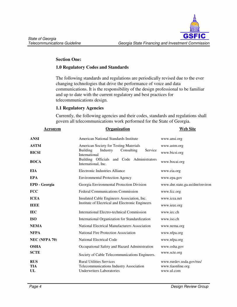
1.1 Regulatory Agencies
Currently, the following agencies and their codes, standards and regulations shall
govern all telecommunications work performed for the State of Georgia.
Acronym Organization Web Site
ANSI American National Standards Institute www.ansi.org
ASTM American Society for Testing Materials www.astm.org
BICSI Building Industry Consulting Service
International www.bicsi.org
BOCA Building Officials and Code Administrators
International, Inc. www.bocai.org
EIA Electronic Industries Alliance www.eia.org
EPA Environmental Protection Agency www.epa.gov
EPD - Georgia Georgia Environmental Protection Division www.dnr.state.ga.us/dnr/environ
FCC Federal Communications Commission www.fcc.org
ICEA Insulated Cable Engineers Association, Inc. www.icea.net
IEEE Institute of Electrical and Electronic Engineers
www.ieee.org
IEC International Electro-technical Commission www.iec.ch
ISO International Organization for Standardization www.iso.ch
NEMA National Electrical Manufacturers Association www.nema.org
NFPA National Fire Protection Association www.nfpa.org
NEC (NFPA 70) National Electrical Code www.nfpa.org
OSHA Occupational Safety and Hazard Administration www.osha.gov
SCTE Society of Cable Telecommunications Engineers.
www.scte.org
RUS Rural Utilities Services www.rurdev.usda.gov/rus/
TIA Telecommunications Industry Association www.tiaonline.org
UL Underwriters Laboratories www.ul.com

Page 5 Design Review Group
State of Georgia Telecommunications Guideline Georgia State Financing and Investment Commission
1.2 National Electrical Code, NFPA 70
The National Fire Protection Association has acted as the sponsor of the National
Electrical Code (NEC) since 1911. The original Code was developed in 1897 as a
result of the united efforts of various insurance, electrical, architectural, and allied
interests. The purpose of the NEC is the practical safeguarding of persons and
property from hazards arising from the use of electricity. The NEC provides the
minimum code requirements for electrical safety. In telecommunications
distribution design, the NEC must be used in concert with the ANSI/EIA/TIA
standards identified below, which are intended to insure the performance of the
telecommunications infrastructure. Designers shall always consult with the local
municipal Authority Having Jurisdiction (Building/Fire Inspector), who may have
additional, more stringent requirements, beyond those contained in the NEC.
The particular sections of the NEC of interest to designers and installers of
telecommunications distribution, telecommunications systems, and information
processing systems are:
Article Description
Article-250 Grounding
Article-300.11 Support & Securing
Article-517 HealthCare Facilities
Article-645 Information Technology Equipment
Article-770 Optical Fiber Cables, and Raceways
Chapter 8 Communications Systems

Page 6 Design Review Group
State of Georgia Telecommunications Guideline Georgia State Financing and Investment Commission
The National Electrical Code is available from:
National Fire Protection Association
1 Batterymarch Park
PO Box 9101
Quincy, MA 02269-9904
1.3 ANSI/TIA/EIA Standards
The Telecommunications Industry Association/Electronics Industry Association
(ANSI/TIA/EIA) engineering standards and publications are designed to serve the
public interest by eliminating misunderstandings between manufacturers and
purchasers. The standards facilitate interchangeability and improvement of
products, and assist the purchaser in selecting and obtaining the proper product for
his particular need.
ANSI/TIA/EIA Standards are updated every 5 years. Due to the rapid changes in
the telecommunications and electronics industries, ANSI/TIA/EIA publishes
periodic Telecommunications System Bulletins (TSB) which provides additional
guidance on technical issues that must be addressed prior to the next scheduled
revision of the Standards. The information contained in TSBs is usually
incorporated into the applicable Standard during the next Standard revision.
Standards and publications are adopted by ANSI/TIA/EIA in accordance with
American National Standards Institute (ANSI) patent policy.
ANSI/TIA/EIA Standards are available from:
Global Engineering Documents
15 Inverness Way East
Englewood, CO 80112-5704
1-800-624-3974
Optical Fiber Systems Test Procedures, ANSI/TIA/EIA-526 (series)
ANSI/TIA/EIA-526 contains a series of test procedures developed to provide
uniform procedures for testing all or part of optical fiber systems or subsystems
intended for optical communications or data transmission use. The base
document is ANSI/TIA/EIA-526.

Page 7 Design Review Group
State of Georgia Telecommunications Guideline Georgia State Financing and Investment Commission
Cabling Standard, ANSI/TIA/EIA-568 (series)
The ANSI/TIA/EIA-568 (series) is the Commercial Building Telecommunications
Cabling Standard. This standard defines a generic telecommunications cabling
system for commercial buildings that will support a multi-product, multi-vendor
environment. It also provides direction for the design of telecommunications
products for commercial enterprise.
The purpose of the standard is to enable planning and installation of building
cabling with little knowledge of the telecommunications products that
subsequently will be installed. Installation of cabling systems during building
construction or renovation is significantly less expensive and less disruptive than
after the building is occupied. ANSI/TIA/EIA-568 establishes performance and
technical criteria for various cabling system configurations for interfacing and
connecting their respective elements.
Pathways, and Spaces, ANSI/EIA/TIA-569 (series)
The ANSI/EIA/TIA-569 (series) is the Commercial Building Standard for
Telecommunications Pathways and Spaces. This standard recognizes three
fundamental concepts related to telecommunications and buildings
(1) Buildings are dynamic.
Over the life of a building, or campus, remodeling is more the rule than the
exception. The standard recognizes that changes will take place.
(2) Building telecommunications systems and media are dynamic.
Over the life of a building, or campus, both telecommunications equipment and
cabling requirements change dramatically. The standard recognizes this fact by
being as independent as possible from specific vendor equipment and media.
(3) Telecommunications is more than just voice and data connectivity.
Telecommunications also encompasses many other building systems including
environmental controls, security, audio, television, sensing, alarms and paging.
Page 8 Design Review Group
State of Georgia Telecommunications Guideline Georgia State Financing and Investment Commission
Telecommunications includes all low voltage signal systems that convey
information within or between buildings.
In order to have a building, or campus, successfully designed, constructed, and
provisioned for telecommunications, it is imperative that the telecommunications
design be incorporated during the preliminary architectural design phase. To
accomplish this, the architect must work closely with the designated
GSFIC/RCDD; and the Agency’s Facilities Coordinator.
Administration Standard, ANSI/TIA/EIA-606 (series)
The ANSI/TIA/EIA-606 (series) is the Administration Standard for the
Telecommunications Infrastructure of Commercial Buildings. Administration of
the telecommunications infrastructure includes documentation of cables,
termination hardware, patching and cross-connection facilities, conduits, other
cable pathways, telecommunications rooms, and other telecommunications
spaces. The purpose of this standard is to provide a uniform administration
scheme that is independent of applications, which may change several times
throughout the life of a building. This standard establishes guidelines for owners,
end users, manufacturers, installers, and facilities administrators involved in the
administration of the telecommunications infrastructure.
Grounding, and Bonding, ANSI/J-STD-607 (series)
The ANSI/J-STD-607 (series) is the Commercial Building Grounding and
Bonding Requirements for Telecommunications. The National Electrical Code
(NEC) provides grounding, bonding, and electrical protection requirements to
ensure life safety. Modern telecommunications systems require an effective
grounding infrastructure to insure optimum performance of the wide variety of
electronic information transport systems that may be used throughout the life of a
building. The grounding and bonding requirements of this standard are additional
technical requirements for telecommunications that are beyond the scope of the
NEC. These standards are intended to work in concert with the cabling topology
specified in ANSI/TIA/EIA-568, and installed in the pathways and spaces designed
in accordance with ANSI/TIA/EIA-569.

Page 9 Design Review Group
State of Georgia Telecommunications Guideline Georgia State Financing and Investment Commission
1.4 Local Area Network Ethernet Standard, IEEE 802.3 (series)
The State of Georgia typically utilizes the Ethernet LAN protocol at all facilities.
All State of Georgia telecommunications infrastructure must be designed to
support the Institute of Electrical and Electronic Engineers (IEEE) Ethernet 802.3
standards. Most State organizations are in the process of migrating to the
1000Base-X Gigabit Ethernet protocol based on the IEEE 802.3z standard. All
newly installed cabling shall support this protocol. Careful consideration must be
given to the multimode optical fiber distance limitations and signal loss
limitations (less than 2.5 dB end-to-end) necessary to support the IEEE 802.3z
protocol.
1.5 BICSI Telecommunications Distribution Methods Manual
BICSI is an ITS Association whose mission is to provide state-of-the-art
telecommunications knowledge to the industry, resulting in good service to the
end user. BICSI develops and publishes the Telecommunications Distribution
Methods Manual (TDMM). The TDMM is not a code or standard. The TDMM is
an extensive volume of information on the various aspects of telecommunications
systems and telecommunications distribution. The TDMM provides discussions
and examples of various engineering methods and design solutions that can be
selected and employed in order to meet the requirements of the NEC and
ANSI/TIA/EIA standards.
Additional BICSI Publications:
ANSI/NECA/BICSI 568-2006, Standard for Installing Commercial Building
Telecommunications Cabling
ANSI/NECA/BICSI 607-2010, Telecommunications Bonding and Grounding
Planning and Installation methods for Commercial Buildings.
BICSI, Telecommunications Distribution Methods Manual, 12
th Edition
BICSI 002-2010, Data Center Design and Implementation Best Practices BICSI, AV Design reference Manual, 1
st edition
BICSI, Electronic Safety and Security Design Reference Manual, 2nd
Edition
BICSI, Information transport systems Installation Methods Manual, 5th
Edition

Page 10 Design Review Group
State of Georgia Telecommunications Guideline Georgia State Financing and Investment Commission
BICSI, Network Design reference Manual, 7th
Edition
BICSI, Outside Plant design Reference Manual, 4th
Edition
BICSI, Wireless Design Reference Manual, 3rd
Edition
BICSI publications are available from:
BICSI
8610HiddenRiverParkway
Tampa, FL 33637-1000
1-800-242-7405
1.6 Local Code, and Regulatory Compliance
Federal, state, and local codes, rules, regulations, and ordinances governing the
work, are as fully part of this manual as if herein repeated or hereto attached.
Contractors shall notify the agency immediately in writing of any possible code
violations. Where the requirements of this manual are more stringent than
applicable codes, rules, regulations, and ordinances, the GTG requirements shall
apply.
All pertaining statutes, ordinances, rules, codes, regulations, standards, and the
lawful orders of all public authorities having jurisdiction over the construction of
ITS will be followed in the design and installation of cabling systems. These
include, without limitation, applicable building codes, and disability regulations
(ADA), municipal codes, fire codes, state statutes and the regulations of the
Occupational Safety and Health Administration (OSHA).
1.7 Adherence to Reference Documents
This manual does not exclude any part of the ANSI/TIA/EIA standards but may
recommend additional practices based upon field experience in state facilities. It
is the responsibility of the designer to be familiar with the most current revision of
the ANSI/TIA/EIA standards and to utilize the standards without exception unless
recommended to do otherwise by this manual. Codes shall be followed; however,
where they may differ with standards, the more stringent code requirement shall
be followed.
Page 11 Design Review Group
State of Georgia Telecommunications Guideline Georgia State Financing and Investment Commission
1.8 Industry Standard Drawings, and Specifications
1.8.1 Overview
The latest (2010) CSI Master Format Construction specifications shall apply to all
projects. The telecommunications ‘T-Series’ drawings shall be included in
addition to the other CSI Divisions. Some drawing elements may be combined
onto a single sheet for smaller projects. Drawings required for a project shall be
determined in the pre-design stage. Some projects may require all of these
drawings and more to convey the intent of the necessary design intent of the ITS.
Drawings shall be provided to address both inter-building and intra-building
telecommunications needs based upon the scope of work developed during the
pre-design stage of the project.
1.8.2 Applicable Drawings
T0 Series Campus or Site Plans – Exterior Pathways and Inter-building Backbones
T1 Series Layout of complete building(s) per floor – Serving Zone Boundaries,
Backbone Systems and Horizontal Pathways
T2 Series Serving Zones Drawings – WAO Locations and reference labeling scheme
T3 Series Detail drawings to scale of the Service Entrance Room (SER), Main Equipment Room
(MER) and Telecommunications Rooms (TR) – detail plan views, elevations, equipment
rack and wall mounted equipment.
T4 Series Typical detail drawings of faceplate labeling, fire stopping, ADA compliance, Safety,
DOT, and other detail drawings as necessary to effectively describe both inter-building
and intra-building design elements.
T5 Series Schedules of cabling and equipment spreadsheets for cutovers.
Page 12 Design Review Group
State of Georgia Telecommunications Guideline Georgia State Financing and Investment Commission
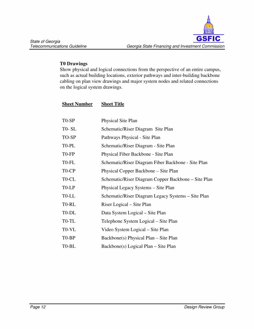
T0 Drawings
Show physical and logical connections from the perspective of an entire campus,
such as actual building locations, exterior pathways and inter-building backbone
cabling on plan view drawings and major system nodes and related connections
on the logical system drawings.
Sheet Number
Sheet Title
T0-SP Physical Site Plan
T0- SL Schematic/Riser Diagram Site Plan
TO-SP Pathways Physical - Site Plan
T0-PL Schematic/Riser Diagram - Site Plan
T0-FP Physical Fiber Backbone - Site Plan
T0-FL Schematic/Riser Diagram Fiber Backbone - Site Plan
T0-CP Physical Copper Backbone – Site Plan
T0-CL Schematic/Riser Diagram Copper Backbone – Site Plan
T0-LP Physical Legacy Systems – Site Plan
T0-LL Schematic/Riser Diagram Legacy Systems – Site Plan
T0-RL Riser Logical – Site Plan
T0-DL Data System Logical – Site Plan
T0-TL Telephone System Logical – Site Plan
T0-VL Video System Logical – Site Plan
T0-BP Backbone(s) Physical Plan – Site Plan
T0-BL Backbone(s) Logical Plan – Site Plan
Page 13 Design Review Group
State of Georgia Telecommunications Guideline Georgia State Financing and Investment Commission
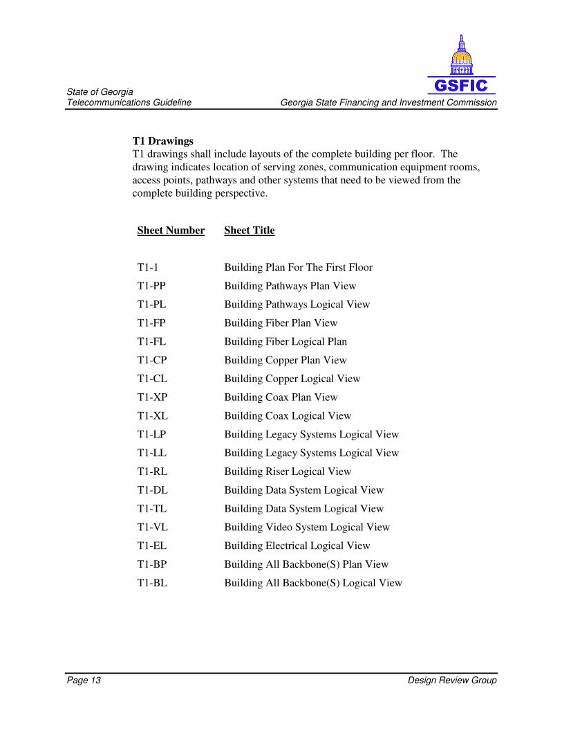
T1 Drawings
T1 drawings shall include layouts of the complete building per floor. The
drawing indicates location of serving zones, communication equipment rooms,
access points, pathways and other systems that need to be viewed from the
complete building perspective.
Sheet Number
Sheet Title
T1-1 Building Plan For The First Floor
T1-PP Building Pathways Plan View
T1-PL Building Pathways Logical View
T1-FP Building Fiber Plan View
T1-FL Building Fiber Logical Plan
T1-CP Building Copper Plan View
T1-CL Building Copper Logical View
T1-XP Building Coax Plan View
T1-XL Building Coax Logical View
T1-LP Building Legacy Systems Logical View
T1-LL Building Legacy Systems Logical View
T1-RL Building Riser Logical View
T1-DL Building Data System Logical View
T1-TL Building Data System Logical View
T1-VL Building Video System Logical View
T1-EL Building Electrical Logical View
T1-BP Building All Backbone(S) Plan View
T1-BL Building All Backbone(S) Logical View

Page 14 Design Review Group
State of Georgia Telecommunications Guideline Georgia State Financing and Investment Commission
T2 Drawings
In these drawings the building is divided up into serving zones. Drawing
indicates outlet locations, telecommunications rooms, access points and detail
callouts/cross-references for telecommunication room details and other congested
areas.
Sheet Number
Sheet Title
T2-1B 1B Serving Zone Drawing
T2-CL Copper Logical Drawing by Riser
T2-PL Pathway Logical Drawing by Riser
T3 Drawings
T3 drawings shall provide a detailed look at telecommunications rooms.
Drawings indicate technology layout (equipment racks, ladder rack, MEP layout,
equipment rack elevations, and backboard elevations. These could also be an
enlargement of congested areas of T1 and T2 drawings.
Sheet Number
Sheet Title
T3-1B Telecommunications Equipment Room 1B
T3-APB Access Points for “B” Riser
T4 Drawings
T4 drawings shall include detailed drawings of typical symbols such as faceplate
labeling, faceplate types, installation procedures, etc.
Sheet Number
Sheet Title
T4-SYM Sample Symbols Drawing
Page 15 Design Review Group
State of Georgia Telecommunications Guideline Georgia State Financing and Investment Commission
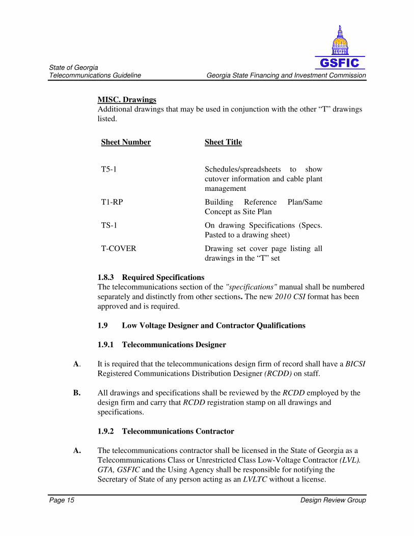
MISC. Drawings
Additional drawings that may be used in conjunction with the other “T” drawings
listed.
Sheet Number
Sheet Title
T5-1 Schedules/spreadsheets to show
cutover information and cable plant
management
T1-RP Building Reference Plan/Same
Concept as Site Plan
TS-1 On drawing Specifications (Specs.
Pasted to a drawing sheet)
T-COVER Drawing set cover page listing all
drawings in the “T” set
1.8.3 Required Specifications
The telecommunications section of the "specifications" manual shall be numbered
separately and distinctly from other sections. The new 2010 CSI format has been
approved and is required.
1.9 Low Voltage Designer and Contractor Qualifications
1.9.1 Telecommunications Designer
A. It is required that the telecommunications design firm of record shall have a BICSI
Registered Communications Distribution Designer (RCDD) on staff.
B. All drawings and specifications shall be reviewed by the RCDD employed by the
design firm and carry that RCDD registration stamp on all drawings and
specifications.
1.9.2 Telecommunications Contractor
A. The telecommunications contractor shall be licensed in the State of Georgia as a
Telecommunications Class or Unrestricted Class Low-Voltage Contractor (LVL).
GTA, GSFIC and the Using Agency shall be responsible for notifying the
Secretary of State of any person acting as an LVLTC without a license.

Page 16 Design Review Group
State of Georgia Telecommunications Guideline Georgia State Financing and Investment Commission
Note: An Electrical Contractors license does not supersede a Low Voltage
License (LVL) and any person engaged in this shall be committing an unlawful
act. When an Electrical Contractor company performs telecommunications work
they must also hold an active Georgia Low Voltage License to legally perform the
work. Subcontracting work by an Electrical Contractor who does not hold an
active LVL to a Low Voltage Licensed Contractor is not allowed. The prime
LVLTC contractor to the General Contractor must be the license holder. The
entire installation must be performed by the LVLTC, no sharing of work between
Electrical Contractors and LVLTC’s is allowed. (i.e. LVLTC must place cable,
terminate and test, etc.)
B. The Low-Voltage Licensed Telecommunications Contractor (LVLTC) shall be
based in the State of Georgia.
C. The installation of the SCS shall be performed by a LVLTC company that is
currently a Manufacturer’s Certified Structured Cabling System installer in good
standing.
D. The LVLTC installation company shall have an RCDD on staff performing the
role of Project Manager and be available for consultation and to attend project
meetings.
E. A full-time LVLTC manager shall be on site whenever work is being performed or
workers are present.
References
The state may, with full cooperation of the LVLTC, visit installations to observe
equipment operations and consult with references. Specified visits and discussion
shall be arranged through the LVLTC; however, the LVLTC personnel shall not be
present during discussions with references. The LVLTC must provide a minimum
of three (3) reference accounts at which similar work, both in scope and design,
have been completed by the LVLTC within the last two (2) years.
Telecommunications is defined as building systems including voice/data services (to
include wireless), distribution and work area outlets, environmental controls,
security, audio, cable television, closed circuit television, sensing, alarms and
paging.
Section Two:
The following are requirements, and are in addition to the above guidelines:

Page 17 Design Review Group
State of Georgia Telecommunications Guideline Georgia State Financing and Investment Commission
1. A minimum of two walls in each Telecommunications space shall be
covered with rigidly fixed, ¾”, A-C grade, and void free plywood, capable of supporting wall mounted telecommunications devices.
2. False ceiling shall not be provided in the ER.
3. Floors shall be covered with light colored, anti-static vinyl tile (see
ANSI/ESD S20.20).
4. Walls and ceiling shall be painted. Finishes shall be light in color to enhance
lighting.
5. All communications equipment rooms shall be equipped with one
emergency powered luminary. The luminaries shall be on in the event of
loss of normal power.
6. The average maintained illumination measured 3 feet AFF in the space shall
be 50 foot–candles.
7. At least one lighting fixture within the room shall be connected to the
emergency lighting circuit for the facility or provided with emergency
battery ballast.
8. Ridged steel conduit or concrete encased PVC conduit shall be used when
routed beneath paved parking lots and/or roadways or under high load areas for all outside plant telecommunications installations.
9. Cables within telecommunications equipment rooms shall be secured to the
cable racking using Velcro cable wraps to arrange cable bundles.
10. Equipment not related to the support telecommunications spaces (e.g.,
piping, ductwork, pneumatic tubing, etc.) shall not be installed in, enter or
pass through the room.
11. Distribution conduits shall be minimum 1” trade size (27 mm) or larger as
required to accommodate the proper fill ratio.
12. A minimum 15 year warranty shall be provided for the installed voice/data telecommunications systems.
Page 18 Design Review Group
State of Georgia Telecommunications Guideline Georgia State Financing and Investment Commission
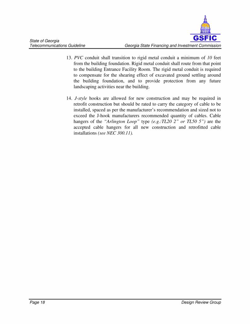
13. PVC conduit shall transition to rigid metal conduit a minimum of 10 feet
from the building foundation. Rigid metal conduit shall route from that point
to the building Entrance Facility Room. The rigid metal conduit is required
to compensate for the shearing effect of excavated ground settling around
the building foundation, and to provide protection from any future
landscaping activities near the building.
14. J-style hooks are allowed for new construction and may be required in
retrofit construction but should be rated to carry the category of cable to be
installed, spaced as per the manufacturer’s recommendation and sized not to
exceed the J-hook manufacturers recommended quantity of cables. Cable
hangers of the “Arlington Loop” type (e.g.:TL20 2” or TL50 5”) are the
accepted cable hangers for all new construction and retrofitted cable
installations (see NEC 300.11).

Page 19 Design Review Group
State of Georgia Telecommunications Guideline Georgia State Financing and Investment Commission
Appendices
APPENDIX A
Glossary of Cabling and Telecommunications Terms and Concepts
AEC – Architects, Engineers, and Consultants.
AMERICAN NATIONAL STANDARDS INSTITUTE (ANSI) – ANSI is the
umbrella organization in the United States for the repository and definition of
standards. ANSI represents the U.S. in the International Standards Organization
(ISO).
AMERICAN WIRE GAUGE (AWG) – The standard gauge for measuring the
diameter of copper, aluminum, and other conductors.
ANSI/EIA/TIA 568 – Approved in 1991, this document specifies the standards for
commercial building telecommunications cabling in North America. The standard
specifically addresses the type of cabling to use, cabling practices, terminations and
connections, and cable performance standards. The current version of this standard
is the NSI/TIA/EIA–568–B series and addenda.
ANSI/EIA/TIA 569 – North American commercial building standard for
telecommunications pathways and spaces. Its purpose is to standardize specific
design and construction practices within and between buildings which are in support
of telecommunications media and equipment. The current version of this standard is
ANSI/TIA/EIA–569–B–2004.
ASYNCHRONOUS TRANSFER MODE (ATM) – A high speed cell–based
switching
and multiplexing technology based on segmentation of voice, data and video into
fixed packets (cells).
ATTENUATION – A reduction in strength or deterioration of an electrical signal
as it passes through a transmission medium. Attenuation generally increases with
frequency, cable length and the number of connections in a circuit. Attenuation is
measured in decibels (dB). In optical fiber, a diminution of the signal as a function
of length traveled.

Page 20 Design Review Group
State of Georgia Telecommunications Guideline Georgia State Financing and Investment Commission
AUTOTEST – A pre–programmed series of tests and pass/fail criteria used by a
hand–held cable test device to determine and certify the category of performance of
data cabling.
BACKBONE – The part of a premises distribution system that carries the heaviest
traffic. Includes a main cable route and facilities for supporting the cable from the
MC to IC; IC to HC; or ER to MC, IC, or TR.
BANDWIDTH – In electrical transmission systems, the range between the highest
and lowest frequencies of a transmission channel. A measure of the information
capacity of the transmission channel. The measured difference at some frequency
between cross–talk and attenuation. Bandwidth varies with the type and method of
transmission. Bandwidth is measured in hertz.
BARRIER – A permanent partition installed in a cable raceway or housing that
provides complete separation of the adjacent compartment.
BASEBAND – A network in which the entire bandwidth of the transmission
medium is used as a single digital signal.
BEND RADIUS – The radius a cable can bend before the risk of breakage or
increase in attenuation occurs. Or, the allowable radius a cable can be bent per a
particular standard.
BER – Bit Error Rate is calculated as follows: The data packet sent, minus the data
packet received, divided by the data packet transmitted.
BICSI – Building Industry Consulting Services International. BICSI, a not–for–
profit telecommunications association, is a world–wide resource for technical
publications, training, conferences, and registration programs for information
transport design and installation.
BIT – A contraction of the term binary digit. A bit can be either 0 or 1 and is the
smallest
possible unit of information in digital code.
BIT/S (BPS) – Bits per second. A measure of speed or data rate. Often combined
with metric prefixes such as Kbps (kilo or thousands of bits per second) and Mbps
(mega or millions of bits per second).
Page 21 Design Review Group
State of Georgia Telecommunications Guideline Georgia State Financing and Investment Commission
BNC – A bayonet–locking connector used to terminate coaxial cables. There is
some disagreement as to whether BNC is an acronym for Bayonet–Neill–
Concelman or Bayonet Nut Coupler.
BONDING – The permanent joining of metallic parts to form an electrically
conductive path that will assure electrical continuity and the capacity to conduct
safely any current likely to be imposed on it.
BROADBAND – A network in which the bandwidth can be shared by multiple
simultaneous signals that are encoded with radio frequency modulations.
BUFFER COATING – Protective material applied to optical fibers.
BUILDING ENTRANCE FACILITY – The area inside a building where
telecommunications cables enter and leave (see Telecommunications Entrance).
BUS – 1) A data path shared by many devices. 2) A linear network topology in
which all workstations are connected to a single cable. On a bus network, such as
Ethernet, all workstations receive all transmissions; only the workstation that the
information is addressed to will use the information.
BYTE – A collection of bits operated upon as a unit, usually 8 bits long. Often used
to represent one character. Also used to measure the capacity of storage devices.
CABLE – A bound or sheathed group of mutually insulated conductors.
CABLE TESTER – A handheld electronic device that is used to measure the
electrical and physical properties of network cabling. Used commonly to certify
cabling to known standards, or as a troubleshooting tool.
CAMPUS – A premises containing more than one building adjacent or near to one
another.
CAMPUS BACKBONE CABLE – The communications cable that is part of the
Campus Backbone Subsystem and that is placed between buildings. There are four
methods of installing campus backbone cable: in–conduit (in underground conduit),
direct–burial (in trenches), aerial (on poles), and in–tunnel (in steam tunnels).

Page 22 Design Review Group
State of Georgia Telecommunications Guideline Georgia State Financing and Investment Commission
CAPACITANCE – The property of a system of conductors and dielectrics that
permits the storage of electrically separated charges when potential differences exist
between the conductors.
CATEGORY OF PERFORMANCE – Copper cable and connector hardware
components, as well as link and channels, are rated to performance categories as
defined by TIA. The ANSI/TIA/EIA 568–B series of standards defines the
categories of performance for new construction.
CATV (COMMUNITY ANTENNA TELEVISION) – A method of delivering
high quality television reception by transmitting signals from a central antenna
throughout the community via coaxial cable. CATV is a broadband transmission
facility which generally uses a 75W coaxial cable to carry numerous frequency–
divided TV channels simultaneously.
CCTV (CLOSED CIRCUIT TELEVISION) – In general, a video channel which
is broadcast to a limited number of locations. Often used in security applications.
CHANNEL – The end–to–end transmission path from equipment cable end in the
TR to the patch cable end in the WA. Per ANSI/TIA/EIA 568–B.1 the channel
includes up to 328’ of horizontal cable; a work area cable; a telecommunications
outlet or connector; an optional transition point or consolidation connector; and two
connection (cross–connect) connected by a patch cable and an equipment cable in
the telecommunications room. When a maximum horizontal length of 328’ is used,
then the total length of the equipment cable, patch cable and work area cable shall
not exceed 33’.
CHARACTERISTIC IMPEDANCE – The impedance that an infinitely long
transmission line would have at its input terminal. If a transmission line is
terminated in its characteristic impedance, it will appear (electrically) to be infinitely
long, thus minimizing signal reflections from the end of the line.
CIRCUIT – 1) (Communications) A bi–directional communications path between
two pieces of associated equipment. 2) (Power) An arrangement of conductors,
devices and utilization equipment (loads) such that current will pass through them.
CLADDING – The material surrounding the core of an optical fiber cable. The
cladding must have a lower index of refraction than the core in order to contain the
light in the core.

Page 23 Design Review Group
State of Georgia Telecommunications Guideline Georgia State Financing and Investment Commission
CLOSED ARCHITECTURE – An architecture that is compatible only with
hardware and software from a single vendor. Contrast with Open Architecture.
COAXIAL CABLE – A type of communication transmission cable in which a
solid center conductor is surrounded by an insulating spacer which in turn is
surrounded by a tubular outer conductor (usually a braid, foil or both). The entire
assembly is then covered with an insulating and protective outer layer. Coaxial
cables have a wide bandwidth and can carry many data, voice and video
conversations simultaneously. Commonly used for Cable TV (CATV) or older
computer networks.
CONDUIT – A rigid or flexible metallic or nonmetallic raceway of circular cross
section in which cables are housed for protection and to prevent burning cable from
spreading flames or smoke in the event of a fire.
CONNECTOR – A device that connects wire or fiber in cable to equipment, other
wires or fibers. A receptacle used with a plug to make electrical connection between
communication circuits. Connectors are considered the female component of a
connector/plug connector. Connectors are typically used at the work area.
CONNECTING BLOCK – A plastic block that houses metal cabling terminals to
provide a connection between two groups of wires. Connecting blocks have
Insulation Displacement Connectors so insulation removed prior to termination is
not required. Major block types are 110 and 66.
CONSOLIDATION POINT – An interconnection between horizontal cables that
extends from building pathways to the work area, typically used to support frequent
rearrangement of open office furniture clusters.
CORE – The central region of an optical fiber through which light is transmitted.
CROSS CONNECT – A facility enabling the termination of cable elements and
their interconnection and/or cross–connection, primarily by means of a patch cable
or jumper.
CROSS CONNECTION – A connection scheme between cabling runs,
subsystems, and equipment using patch cables or jumpers that attach to connecting
hardware on each end.

Page 24 Design Review Group
State of Georgia Telecommunications Guideline Georgia State Financing and Investment Commission
CROSSTALK – The phenomenon in which a signal transmitted on one circuit or
channel of a transmission system creates an unwanted signal in another circuit or
channel, generally related to wire placement, shielding, and transmission techniques.
Crosstalk interferes with the desired data signal. The level of unwanted crosstalk in
network cabling can be determined by the use of handheld testers.
DECIBEL (dB) – A unit for measuring the relative strength of a signal. Usually
expressed as the logarithmic ratio of the strength of a transmitted signal to the
strength of the original signal. A 3 dB increase in signal strength is twice the
original signal. A 3 dB decrease is half the original signal.
DELAY – In data communications, the time between transmission and reception of
a signal. Usually expressed in nanoseconds. Also see Propagation Delay.
DELAY SKEW – The difference in time between the arrival (reception) of a data
signal and subsequent related data signals. Usually expressed in nanoseconds.
DEMARCATION – A point at which two services may interface and identify the
division of responsibility, such as the point of interconnection between telephone
company facilities and the user’s terminal equipment.
DUPLEX – Simultaneous bi–directional transmission over the same wire pair.
EIA (ELECTRONIC INDUSTRIES ASSOCIATION) – A consultative group of
manufacturers recognized as the standards writing group in the United States for
electronic equipment.
ELFEXT – Equal Level Far End Crosstalk; a measure of the unwanted signal
coupling, expressed in dB relative to the received (attenuated) signal level, from a
transmitter at the far end into the neighboring pairs measured at the near end.
Characterizing ELFEXT is important for cabling links intended to support 4 pair,
full–duplex network transmissions.
EMI/RFI (ELECTROMAGNETIC INTERFERENCE/RADIO FREQUENCY
INTERFERENCE) – The interference in signal transmission or reception resulting
from the radiation of undesirable electrical or magnetic fields.
ENTRANCE FACILITY – The Entrance Facility is an entrance to the building for
both public and private network service cables, including the entrance point at the
building wall and continuing to the entrance room or space.

Page 25 Design Review Group
State of Georgia Telecommunications Guideline Georgia State Financing and Investment Commission
EQUIPMENT ROOM (ER) – An Equipment Room is a centralized space for
housing telecommunications equipment. It is differentiated from the
Telecommunications Room by the type of equipment used; the room serves a
building or multiple buildings in a campus environment.
ETHERNET – A baseband local area network used for connecting computers and
terminals, etc., within the same building. Ethernet was marketed (and trademarked)
by Xerox and developed jointly by Digital Equipment Corporation, Intel and Xerox.
It is the basis for the IEEE Standard 802.3. It employs CSMA/CD as the network
access method, and is popularly deployed as 10BASET, 100BASET, and
1000BASET, where 10, 100, or 1000 is the data transfer rate in megabits/second,
BASE indicates Baseband transmission, and T signifies Twisted Pair as the medium.
FAR END CROSSTALK (FEXT) – Measure of unwanted signal coupling from a
transmitter at the far end into neighboring pairs measured at the near end.
FERRULE – A component of an optical fiber connection that aligns and protects
the stripped end of a fiber.
FIBER LOSS (Optical Loss) – The attenuation (decrease) of the light signal in
optical fiber transmission. Optical loss is directly related to the length of fiber and
the quality and number of connections and splices in a fiber segment.
FIRE–RATED POKE–THROUGH – A cable distribution device which is fitted
through a pre–drilled core hole in the floor and allows cables to be fed from the
floor below.
FLOOR BOX – A cast iron, stamped steel or nonmetallic box placed in the
concrete floor (prior to pouring the concrete slab) of a building which is fed via
conduit and used to house voice, data, power and video connections.
FULL DUPLEX – Simultaneous bi–directional signal transmission.
FURNITURE CLUSTER – A contiguous group of personal work areas, usually
constructed from furniture, typically including partitions of other space division,
work surfaces, storage and seating. The work area cluster does not span aisles; all
components are in contact or close proximity.
GSFIC – Georgia State Finance and Investment Commission

Page 26 Design Review Group
State of Georgia Telecommunications Guideline Georgia State Financing and Investment Commission
GHz (GIGAHERTZ) – A unit of frequency equal to one billion hertz
(1,000,000,000 cycles per second).
GROUNDING CONDUCTOR – The conductor used to connect the grounding
electrode to the building’s main grounding bus bar.
GROUNDING ELECTRODE – A conductor of a group of conductors (usually a
rod, pipe or plate) in direct contact with the earth providing a low impedance
connection to the earth.
HALF DUPLEX – A circuit which provides transmission alternately in either
direction.
HEADROOM – The number of decibels by which a system exceeds the minimum
defined requirements.
HERTZ (Hz) – A unit of frequency or bandwidth equal to one cycle per second.
HOME RUNS – A pathway or cable between two locations without a point of
access in between. Characterized in star topologies.
HORIZONTAL CABLING – The cabling between and including the
telecommunications outlet/connector and the horizontal cross connect.
HORIZONTAL CROSS CONNECT (HC) – A cross connect of horizontal
cabling to other cabling, i.e., horizontal, backbone, equipment.
HUB – Connection point for circuits or a network. Hubs may be active or passive
HYBRID CABLE – An assembly of 2 or more cables of the same or different
types or categories covered by one overall sheath.
IEEE – Institute of Electrical and Electronics Engineers.
IMPEDANCE – A unit of measure, expressed in ohms, of the total opposition
(resistance, capacitance and inductance) offered to the flow of an alternating current.
INFRASTRUCTURE, TELECOMMUNICATIONS – A collection of those
telecommunications components, excluding equipment that together provides the
basic support for the distribution of all information within a building or campus.

Page 27 Design Review Group
State of Georgia Telecommunications Guideline Georgia State Financing and Investment Commission
ISO – International Standards Organization. The body which promotes the
development of worldwide commercial and industrial standards.
INSERTION LOSS – The reduction in the amount of power received before and
after the insertion of a component (i.e., connector, coupler or splice) into a
previously continuous transmission line. Optical fiber insertion loss is referred to as
‘power loss’.
INSULATION DISPLACEMENT – A type of wire terminal that requires no wire
stripping; when the wire is correctly attached, its insulation is displaced (pierced) to
form a connection. A popular form of insulation displacement termination is the 110
system.
INTERCONNECTION – A connection scheme that provides for the direct
connection of a cable to another cable or to an equipment cable without a patch
cable or jumper.
INTERMEDIATE CROSS CONNECT (IC) – A cross connect between first
level and second level backbone cabling.
ISDN – Integrated Services Digital Network: an international communications
standard for sending voice, video, and data over digital telephone lines or normal
telephone wires.
JACKET – The flexible covering of a cable, used to protect the color–coded
conductors inside. Also referred to as a cable's "sheath".
JUMPER – An assembly of two twisted wires without connectors used to join
telecommunications circuits/links at the cross connect.
LEC (LOCAL EXCHANGE CARRIER) – A private communications utility
company or a government organization that furnishes services to the general public.
It is typically licensed or regulated by a state or federal government agency.
LED (LIGHT EMITTING DIODE) – A semiconductor diode which emits light
when a current is passed through it. In lightwave transmission systems, LEDs or
lasers are used as light sources.
Page 28 Design Review Group
State of Georgia Telecommunications Guideline Georgia State Financing and Investment Commission
LINK – The link is regarded as the permanent portion of the cabling system. A test
configuration for the link consists of up to 90m (295’) of horizontal cabling, a
telecommunications outlet/connector, and up to two cross connect connections in a
telecommunications room. The link specifically excludes patch cables and
equipment cables.
LOCAL AREA NETWORK (LAN) – A non–public data communications
network confined to a limited geographic area used to provide communication
between computers and peripherals.
LOOPBACK – A type of diagnostic test in which a transmitted signal is returned to
the sending device after passing through a data communications link or network.
This test allows the comparison of a returned signal with the transmitted signal.
LOSS – Reduction in signal strength, expressed in decibels (dB). Opposite of gain.
MAIN CROSS CONNECT (MC) – A cross connect for first level backbone
cables, entrance cables, and equipment cables.
MHz (MEGA HERTZ) – A unit of frequency equal to one million hertz
(1,000,000 hertz).
METROPOLITAN AREA NETWORK (MAN) – An extended LAN operating
within a metropolitan area and providing an integrated set of services for real–time
data, voice and image transmission.
MICRON – A unit of length equal to one millionth of a meter (.000001 meter).
Short for micrometer.
MIPS – Millions of Instructions Per Second. A measure of processing power.
MODEM (MODULATOR DEMODULATOR) – A device which converts
digital signals to analog signals (and vice–versa) for transmission over the telephone
network, which usually is analog.
MT–RJ – A small form factor fiber connector that features a high–density design
and RJ45 locking mechanism.
MULTIFIBER CABLE – An optical fiber cable containing two or more fibers,
each providing a separate information channel.
Page 29 Design Review Group
State of Georgia Telecommunications Guideline Georgia State Financing and Investment Commission
MULTIMEDIA – A means of conveying information with components in different
media such as voice, music, text, graphics, image and video.
MULTIMODE OPTICAL FIBER – An optical fiber that will allow many bound
modes to propagate. The fiber may be either a grade–index or step–index fiber.
Typically used in premise environments only. Multimode Fiber cores are typically
either 62.5 or 50 microns in diameter. See Single Mode Fiber.
MUTOA – A Multi–User Telecommunications Outlet Assembly, used to facilitate
furniture rearrangement in open office areas. Defined by ANSI/TIA/EIA 568B–1.
NANOSECOND (NS) – One billionth of a second.
NATIONAL ELECTRICAL CODE (NEC) – A nationally recognized safety
standard for the design, construction, and maintenance of electrical circuits.
NETWORK – A formalized definition of the structure and protocols of a computer
network.
NETWORK INTERFACE – The point of interconnection between telephone
company facilities and terminal equipment, protective apparatus or cabling at a
subscriber’s premises.
NEXT (NEAR END CROSSTALK) – Electrical noise coupled from different
wire pairs within a common sheath.
NODE – In general, any point of interconnection to a network where service is
provided, used or communication channels are interconnected.
NOISE – Random electrical signals, introduced by circuit components or natural
disturbances, which degrade the performance of a communication channel.
OPEN ARCHITECTURE – An architecture that is compatible with hardware and
software from any of many vendors.
OPEN OFFICE – An office where a floor space division is provided by furniture,
furniture partitions, or both instead of by building walls.
OPEN SYSYTEM INTERCONNECTION (OSI) – An internationally accepted
framework of standards developed by the International Standards Association, for
communication between two systems made by different vendors.

Page 30 Design Review Group
State of Georgia Telecommunications Guideline Georgia State Financing and Investment Commission
OPTICAL FIBERS – The technology in which communication signals in the form
of modulated light beams are transmitted over a glass or plastic fiber transmission
medium, and then demodulated to electrical signals by a light sensitive receiver.
OPTICAL TIME–DOMAIN REFLECTOMETER (OTDR) – An instrument
that characterizes cable loss by measuring the backscatter and reflecting of injected
light as a function of time. It is most useful for locating splices, connections, and
breaks. It is not as useful as an optical fiber test set for accurately measuring cable
attenuation, and shall therefore not be used to certify an optical link.
PASSIVE EQUIPMENT – Components and/or equipment that pass active signals
without conversion.
PATCH CABLE – A short length of copper or optical fiber cable with connectors
on each end used to join communications circuits as a cross connect.
PATCH PANEL – A cross connect system of mateable connectors, utilizing patch
cables, that facilitates administration.
PATHWAY – A facility for the placement of telecommunications cable.
PEDESTAL – A device usually mounted on the floor, which is used to house
voice/data jacks or power outlets at the point of use.
PERSONAL COMPUTER (PC) – A computer for personal, single–user use, as
opposed to mainframes or minicomputers which are shared by many users.
PERMANENT LINK – The transmission path between two mated interfaces of
cabling, excluding equipment cables, work area cables and cross–connections.
PHYSICAL LAYER – Within the OSI Model, the lowest level (Level 1) of
network processing, below the link layer, concerned with the electrical, mechanical,
and handshaking procedures over the interface that connects a device to a
transmission medium.
PLENUM – In building construction, the space that is used for air circulation in
heating and air conditioning systems, typically between the structural ceiling and the
suspended ceiling or under a raised floor. The plenum space is often used to house
the communication cables for the building's telecommunications network. In those
instances, plenum cable must be used.

Page 31 Design Review Group
State of Georgia Telecommunications Guideline Georgia State Financing and Investment Commission
PLENUM CABLE – Plenum cable is coated with a fire–retardant coating (usually
Teflon) so that in case of a fire it does not give off toxic gasses and smoke as it
burns. Required for cables used in plenum areas.
PLUG – The male component of a connection. It is typically used on one or both
ends of equipment cables or on cabling for interconnect or cross connect.
POINT–TO–POINT TRANSMISSION – An uninterrupted connection between
two pieces of equipment.
PORT – A functional unit of a node through which data can enter or leave a data
network.
POWER METER – The most effective tool to measure light loss in an optical fiber
link. Typically used to describe a test set used to accurately measure optical loss in
an optical fiber link. Comprised of a light source, capable of injecting light at
different frequencies into the fiber link; and the power meter itself, which when
properly calibrated will display the amount of optical loss for that link.
POWER/COMMUNICATIONS POLE – A raceway placed between the ceiling
and floor used in conjunction with a ceiling distribution system for the purpose of
distributing communication and power service to a work area. Also called Utility
Pole, Service Pole or Tele–power Pole.
POWERSUM CROSSTALK – A measure of the combined crosstalk on a receive
pair from all near–end disturbers operating simultaneously.
PREMISES CABLING – The entire cabling system on the user’s premises used
for transmission of voice, data, video and power.
PRINTED CIRCUIT – A copper foil circuit formed on one or both faces of an
insulating board to which circuit components are soldered. The copper foil pattern
serves to connect components and is produced either by etching or plating.
PRIVATE BRANCH EXCHANGE (PBX) – A private telephone switching
system, usually located on a customer’s premises connecting a common group of
lines from one or more central offices to provide service to a number of individual
phones. Now used interchangeably with PABX (Private Automatic Branch
Exchange).

Page 32 Design Review Group
State of Georgia Telecommunications Guideline Georgia State Financing and Investment Commission
PROPAGATION DELAY – The time it takes for a signal to travel from one point
on a circuit to another.
PROTOCOL – A formal set of conventions governing the format and control of
inputs and outputs between two communication devices or processes.
PVC – Polyvinyl Chloride. A type of plastic commonly used for cladding
telecommunications cable.
PUBLIC SWITCHED NETWORK – Any common carrier network that provides
circuit switching between public users, such as the public telephone network, telex
or MCI’s Execunet (long distance telephone service).
RACEWAY – Any channel designed for holding wires, cables or busbars such as
conduit, surface raceways, cellular floors or cable troughs.
RCDD – The Registered Communications Distribution Designer is a professional
engineering status granted by BICSI based on knowledge of the telecommunications
cabling industry.
REPEATER – In digital transmission, equipment that receives a pulse train,
amplifies it, re–times it, and then reconstructs the signal for retransmission.
RETURN LOSS – The measure of the reflected energy caused by impedance
mismatches in a cabling system.
RISER – The conduit or path between floors of a building into which telephone and
other utility cables are placed to bring service from one floor to another.
RJ (REGISTERED JACK) – Registered Jack (RJ) cabling configurations
developed by the Bell System for connection of customer premises equipment to the
public network. Registered jacks serve telephone and data applications and are
registered with the FCC. The most common types are: RJ45 and RJ11.
SC – Designation for an optical connector featuring a 2.5mm physically contacting
ferrule with a push–pull mating design. This connector is recommended in the
ANSI/TIA/EIA–568B–1 Standard for structured cabling.
SFF (SMALL FORM FACTOR) – An ANSI/TIA/EIA approved fiber
adapter/connector system that provides two fiber strands in a surface area similar to
UTP (RJ–style) connection.

Page 33 Design Review Group
State of Georgia Telecommunications Guideline Georgia State Financing and Investment Commission
SHIELD (SCREEN) – A metallic layer usually in the form of a braid or foil
surrounding one or more electrical conductors to insulate them from
electromagnetic interference.
SINGLEMODE OPTICAL FIBER – An optical fiber that will allow only one
mode to propagate. This fiber is typically a step index fiber and typically has a core
diameter of 8.3 microns.
SLEEVES – Short lengths of rigid metal pipe, approximately 4 in. (10.1 cm) in
diameter, located in the telecommunications room (TR), which allow cables to pass
from floor to floor when TRs are vertically aligned. Sleeves also provide for easy
pulling of cable.
SLOTS – Openings in the floor of riser telecommunications closets that allow
cables to pass thorough from floor to floor when closets are vertically aligned. A
slot accommodates more cables than an individual sleeve.
SPLICE – The joining of two or more cables by connecting the conductors pair to
pair. Not allowed with twisted pair cables per the 568B Standard.
ST – Designation for the “straight tip” connector developed by AT&T. This optical
connector features a physically contacting non–rotating 2.5mm ferrule design and
bayonet connector–to–adapter mating.
STAR – A physical point-to-point network topology.
STRUCTURED CABLING SYSTEM – A telecommunications cabling system,
capable of supporting a wide range of applications. Generic cabling can be installed
without prior knowledge of the required applications. Application–specific hardware
is not a part of generic cabling.
SUBMINATURE D CONNECTOR – A family of multi–pin data connectors used
in RS232–C communications. The connectors are available in 9, 15, 25 and 37 pin
configurations; sometimes referred to as DB9, DB15, DB25 and DB37 connectors
respectively.
SURGE SUPPRESSION – The process by which transient voltage surges are
prevented from reaching sensitive electronic equipment.
SURFACE RACEWAY – A cable distribution method in which channels
containing cables are run along or within the baseboards of a building.

Page 34 Design Review Group
State of Georgia Telecommunications Guideline Georgia State Financing and Investment Commission
SWITCHING – A function carried out by a switching hub, alleviating traffic by
making virtual connections between transmitting and receiving nodes.
T1 – A digital transmission link with 1.544 Mbps bandwidth. T1 operates on two
twisted pairs and can handle 24 voice conversations, each digitized at 64 Kbps.
More voice channels are available with advanced digital voice encoding techniques.
T1 CARRIER – The AT&T digital transmission system which transmits data at
1.544 Mbps (See also T1).
TELECOMMUNICATIONS – For the purposes of this Glossary, a term
encompassing voice, audio/visual, and data communications in the form of coded
signals transmitted over media.
TELECOMMUNICATIONS OUTLET – A device where the horizontal cable
terminates in the Work Area (WA). The telecommunications outlet provides the
interface to the work area cabling.
TELECOMMUNICATIONS ROOM (TR) – A Telecommunications Room is an
enclosed space for housing telecommunications equipment, cable terminations and
cross–connect cabling. Typically, the room serves a floor and is the location of
horizontal cross–connects.
TELECOMMUNICATIONS ENTRANCE – The point where
telecommunications lines enter or leave the building.
TERMINATION – The act of attaching connectors to bare cabling. In the case of
data cabling, terminations must be in accordance with standard cabling codes and
standards.
TOPOLOGY – The geometric description of the physical or logical connections of
a telecommunications system; typically described as bus, ring or star.
TRANSCEIVER – A single device capable of both sending and receiving
information.
TRANSIENT – An abrupt change in voltage, of short duration, which may cause
signal impairments, loss of memory or physical damage to equipment.
TRANSMISSION MEDIA – Anything such as wire, coaxial cable, optical fibers,
air or vacuum that is used to carry an electrical signal.
Page 35 Design Review Group
State of Georgia Telecommunications Guideline Georgia State Financing and Investment Commission
TRUNK – A specialized communications path between two points, one of them
usually being a telephone company central office or switching center.
TWISTED PAIR CABLE – A type of communication transmission cable in which
two individually insulated wires are twisted around each other to reduce induction
(thus interference) from one wire to the other. The pair may be surrounded by a
shield, insulating jacket or additional pairs of wires.
USOC – Universal Service Ordering Codes (USOC) are a series of Registered Jack
(RJ) cabling configurations developed by the Bell System for connection of
customer premises single line equipment to the public network.
UTP – Unshielded twisted pair copper cable.
WAVELENGTH – The length of an electromagnetic waveform as measured from
any point on one wave to the corresponding point on an adjacent wave, such as from
crest to crest. Wavelength is inversely proportional to frequency.
WIDE AREA NETWORK (WAN) – A communications network designed to
serve hundreds or thousands of miles using common carrier–provided lines, such as
the nationwide telephone network. Compare with LAN.
WIDEBAND – A communications channel or medium having a bandwidth
sufficient to carry multiple voice/video or data signals simultaneously.
WIRE – A single copper conductor/wire covered with a plastic jacket.
WORK AREA / WORK STATION (WA) – A building space where the
occupants interact with telecommunications equipment.

Page 36 Design Review Group
State of Georgia Telecommunications Guideline Georgia State Financing and Investment Commission
APPENDIX B – REFERENCES
Codes and Standards
• Federal Aviation Administration FCC Docket 21006— Frequency Accuracy.
Washington, D. C.: Federal Aviation Administration.
• Federal Communications Commission Code of Federal Regulations (CFR) —
10CFR47, Part 76.605.
• Signal Quality for CATV Washington, D. C.: Federal Communications
Commission.
• Institute of Electrical and Electronics Engineers, Inc. Standards and Guidelines
New York: Institute of Electrical and Electronics Engineers, Inc.
• National Fire Protection Association, Inc. National Electrical Code ® 1999 ed.
Quincy, Mass.: National Fire Protection Association, Inc., 1998.
• Publications and Industry Standards Exton, Penn.: Society for Cable
Telecommunications Engineers, Inc.
• ANSI/ TIA/ EIA– 492AAAB Detail Specification for 50 µm Core Diameter/
125 µm Cladding Diameter Class 1a Multimode, Graded– Index Optical Wave
guide Fibers Arlington, Va.: Telecommunications Industry Association/
Electronic Industries Alliance, November 1998.
• NSI/ TIA/ EIA– 492CAAA Detail Specification for Class IVa Dispersion—
Unshifted Single– Mode Optical Fibers. Arlington, Va.: Telecommunications
Industry Association/Electronic Industries Alliance, May 1998.
• ANSI/ TIA/ EIA– 568B. Commercial Building Telecommunications Cabling
Standard Arlington, Va.: Telecommunications Industry Association/ Electronic
Industries Alliance, October 1995.
• ANSI/ TIA/ EIA– 569A A. Commercial Building Standard for
Telecommunications Pathways and Spaces Arlington, Va.: Telecommunications
Industry Association/Electronic Industries Alliance, February 1998.

Page 37 Design Review Group
State of Georgia Telecommunications Guideline Georgia State Financing and Investment Commission
• ANSI/ TIA/ EIA– 606A Administration Standard for the Telecommunications
Infrastructure of Commercial Buildings Arlington, Va.: Telecommunications
Industry Association/Electronic Industries Alliance, February 1993.
• ANSI/ TIA/ EIA– 758 Customer– Owned OSP Telecommunications Cabling
Standard. Arlington, Va.: Telecommunications Industry Association/ Electronic
Industries Alliance, February 1999. Telcableia Technologies, Inc. (Bellcore).
TR– TSY– 000100 Issue Bulletin.Morristown, N. J.: Telcableia Technologies,
Inc. Replaced by GR– 421– CORE, Generic Requirements for Metallic
Telecommunications Cables, December 1998.
• TR– TSY– 000107 Issue 2 Bulletin. Morristown, N. J.: Telcableia Technologies,
Inc. Replaced by GR–421– CORE, Generic Requirements for Metallic
Telecommunications Cables, December 1998.
• American National Standards Institute. ANSI T1.311. American National
Standard for Telecommunications — DC Power Systems—
Telecommunications Environmental Protection New York: American National
Standards Institute, 1998.
• ANSI T1.313. American National Standard for Telecommunications—
Electrical Protection for Telecommunications Central Offices and Similar Type
Facilities. New York: American National Standards Institute, 1998.
• ANSI/ IEEE Standard 142. Recommended Practice for Grounding of Industrial
and Commercial Power Systems. New York: Institute of Electrical and
Electronics Engineers, Inc., 1991. Also known as the IEEE Green Book.
• ANSI/ IEEE Standard 241. Recommended Practices for Electrical Power
Systems in Commercial Buildings. New York: Institute of Electrical and
Electronics Engineers, Inc., 1990. Also known as the IEEE Gray Book.
• ANSI/ IEEE Standard 446. Recommended Practice for Emergency and Standby
Power Systems for Industrial and Commercial Applications. New York: Institute
of Electrical and Electronics Engineers, Inc., 1987. Also known as the IEEE
Orange Book.
Page 38 Design Review Group
State of Georgia Telecommunications Guideline Georgia State Financing and Investment Commission
• ANSI/ IEEE Standard 1100 Recommended Practice for Powering and
Grounding Sensitive Electronic Equipment in Industrial and Commercial Power
Systems New York: Institute of Electrical and Electronics Engineers, Inc., 1999.
Also known as the IEEE Emerald Book.
• American National Standards Institute/ National Fire Protection Association,
Inc. ANSI/NFPA– 70 National Electrical Code ®. Quincy, Mass.: National Fire
Protection Association, Inc., 1999.
• American National Standards Institute/ Telecommunications Industry
Association/Electronic Industries Alliance
• ANSI/ TIA/ EIA– 607 Commercial Building Grounding and Bonding
Requirements for Telecommunications. Arlington, Va.: Telecommunications
Industry Association/Electronic Industries Alliance, August 1994.
Page 39 Design Review Group
State of Georgia Telecommunications Guideline Georgia State Financing and Investment Commission
Selected Guidelines
Argonne National Laboratory, Electronics and Computing Technologies Division,
Specifications for OSP Telecommunications Facilities, “Installation of Copper and
Optical fiber Cable Systems”, November 1997,
http://www.ect.anl.gov/telecommunications/outsideplantspecs.htm
Bucknell University, “Cabling Specifications, Section 17100 – Network
Communications Systems”, June 1998
http://www.isr.bucknell.edu/network/powerpoint/cablingspecifications
The University of California Irvine, Network and Academic Computing Services,
Network and Telephone Services, “Project Planning Guidelines”, June 2000
California State University, “Telecommunications Infrastructure Planning
Guidelines”, http://www.calstate.edu/tier3/PPD/AE/Design_STDS.html.
The University of Chicago, “Structured Cabling Specifications, Universal Cabling
Plan”, September 2000
The University of Connecticut, “Telecommunications Design Guide and Standards”,
http://www.comm.uconn.edu/tscontents.htm
East Carolina University, “Telecommunications Standards”, June 2001
Emory University, “General Building Specifications for NetCom, Communications
Standards”, December 2000
The University of Florida, Physical Plant Division, “Telecommunications
Construction Standards”, August 2001,
http://ppd.ufl.edu/telecommunications/telecom–construction.html
The University of Georgia, Policy 33.4, “Cabling Specifications for Telephone, Data
and Video Services”, http://www.uga.edu/netinfo
The Board of Regents of the University System of Georgia, “Facilities Guidelines
for Instructional Technology”, December 2001
Houston Independent School District, Offices of Technology and Information
Services, “HISD Network Cabling Standards”, , January 2000,
http://dept.houstonisd.org/technology/hisd%20network%

Page 40 Design Review Group
State of Georgia Telecommunications Guideline Georgia State Financing and Investment Commission
Indiana University Southeast, “Technical Standards for Telecommunications
Distribution Facilities”, June 1993
The University of Kentucky, Communication and Network Systems,
“Telecommunications Standards”, Revision 4.0, January 2002
The State of Minnesota, Inter Technologies Group, Building Infrastructure
Standards for State Owned Buildings, September 2000
The State of North Carolina, State Telecommunications Services, “STS–1000
Telecommunications Cabling Guidelines”,
http://www.its.state.nc.us/about/divisions/ITS/Forms/STS1000.pdf
Commonwealth of Virginia, Department of Technology Planning, Information
Technology Resource Management, “Networking, Telecommunications and
Cabling Standard”, http://www.cim.state.va.us/pubs/standards/ NET2001–01–1–
NetworkingTelecommunicationsAndCablingStandard.doc
Oakland Unified School District, Research and Development Laboratory for
Learning Technologies (Technology Services Department), “System Installation and
Cabling Guide”, January 2, 2001,
http://webtest.ousd.k12.ca.us/svrapps/ousdgs/default.asp
Sacramento Municipal Utility District, “Electric Service Requirements, Section V,
Customer–Owned Service Poles, Engineering Specification T005”, August 2001
The State of Washington, Department of Information Services, “Architecture
Standards, Computing and Telecommunications”,
http://www.wa.gov/dis/portfolio/computingandtelecommstands.htm, December
2000
The University of Waterloo, Waterloo Canada, “Cable Plant Procedures and
Guidelines”, Rev 2.0, December 2001

Page 41 Design Review Group
State of Georgia Telecommunications Guideline Georgia State Financing and Investment Commission
Other Reference Sources
Building Industry Consulting Service International (BICSI) – Telecom trade
association & developer of TDM manuals
Telecommunication Industry Association (TIA) – Telecommunications standards
Underwriters Laboratory (UL) – Testing organization (safety)
Occupational Safety and Health Administration (OSHA) – Worker Safety
National Electric Code (NEC) – Intra-building electrical safety
National Electric Safety Code (NESC) – Inter-building electrical safety
American National Standards Institute (ANSI) – Standards
American Insurance Association (AIA) – Insurance standards for buildings and
infrastructure
Insulated Cable Engineers Association (ICEA) – Manufacturer’s organization that
writes
specifications for cable
Building officials and Code Administration (BOCA) – Building Codes
National Fire Protection Association (NFPA) – Fire safety codes
National Institute of Standards and Technology (NIST) – Technology Standards
ATM Forum – Standards body for ATM standards
International Organization for Standards (ISO) – Produces standards documents
Institute of Electrical and Electronics Engineers (IEEE) – Electronics, Telecom, and
Electrical standards
Federal Communications Commission (FCC)
The Americans Disabilities Act (ADA) – Federal Regulation

Page 42 Design Review Group
State of Georgia Telecommunications Guideline Georgia State Financing and Investment Commission
Bell Operations and Construction Standards (BOCS) – Outside/Entrance
Plant/USOC
AT&T Plant Standards – Outside/Entrance Plant
Rural Utilities Services Specifications (RUS) – PE_89 OSP Cable