networking now - skkumonet.skku.edu/wp-content/uploads/2016/09/networking_now... · 2016-10-05 ·...
TRANSCRIPT

Sungkyunkwan University
Copyright 2000-2016 Networking Laboratory
Networking Now
Hyunseung ChooNetworking Laboratory
Sungkyunkwan University
[email protected]://monet.skku.ac.kr

Networking Now 2016 Networking Laboratory 2/237
MANET / WSN
Overview page 4~
Flooding / Broadcasting page 17~
Routing: Ad Hoc Networks page 39~
Routing: Sensor Networks page 93~
Mobile Sinks page 120~
Localization page 130~
Geographic Routing page 146~
Coverage Problem page 196~
Data Aggregation and Collection page 209~
Scheduling page 214~
Developments page 227~
Contents

Networking Now 2016 Networking Laboratory 3/237
MANET / WSN
- Grand ICT 연구센터지원사업라이프컴패니온쉽경험을위한지능형인터랙션융합연구
- 무선포함접속방식에독립적인차세대네트워킹기술개발SDN/NFV기반의기업유무선통합네트워크를위한액세스기술독립적오픈소스컨트롤러개발
- 자율제어네트워킹및 자율관리핵심기술개발생체모방자율제어시스템및자율관리/통합플랫폼구축
- 스마트TV 2.0 소프트웨어플랫폼M2M을위한디바이스인터랙션기술개발
- 첨단인터랙션을위한기반 SW 융합기술연구인간과기기, 기기와기기간의첨단인터랙션을위한융합 SW중심의기반SW 개발

Networking Now 2016 Networking Laboratory 4/237
Overview
Networking Now 2016 Networking Laboratory 5/237
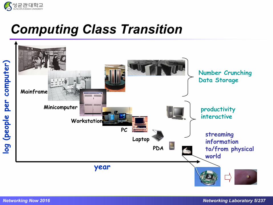
Computing Class Transition
year
log
(peop
le p
er
compu
ter)
streaming informationto/from physical world
Number CrunchingData Storage
productivityinteractive
Mainframe
Minicomputer
Workstation
PC
Laptop
PDA

Networking Now 2016 Networking Laboratory 6/237
MANETs & WSNs
Wireless Sensor Networks
The growth of laptops and 802.11/Wi-
Fi wireless networking have made
Mobile Ad-hoc Networks (MANETs) a
popular research topic since the mid- to
late 1990s
Based on the development of devices
and MANETs, Wireless Sensor
Networks (WSNs) are becoming a “hot”
research topic
Mobile Ad hoc Networks (MANETs)

Networking Now 2016 Networking Laboratory 7/237
A “mobile ad hoc network” (MANET) is an autonomous system of mobile routers
connected by wireless link--the union of which form an arbitrary graph
The routers are free to move randomly and organize themselves arbitrarily; thus,
the network’s wireless topology may change rapidly and un-predictably
MANETs
• Routing protocols
• QoS
• Medium access control
• Low power design
• Mobility management
• Security
Challenges
Evolution of Ad hoc Networks
The Early Influence of Military Applications
Ad hoc Networks and the Internet
The Internet of Things and SDN-based Ad hoc
networking

Networking Now 2016 Networking Laboratory 8/237
What is WSNs?
Network of thousands of extremely small, low power devices
Network of equipments which are programmable computing, multiple
sensing, communication capability
Motivation: robustness, scalability, energy efficiency
*Ref: Wireless Sensor Network Survey, Computer Networks Journal, I. Akilydiz , et al.

Networking Now 2016 Networking Laboratory 9/237
Preliminaries (1/2)
*Ref: Wireless Sensor Network Survey, Computer Networks Journal, I. Akilydiz , et al.
Transducer: converts a physical phenomenon into electrical signals
Sensor Node:
A device capable of physical sensing of environmental phenomena or events,
processing sensed data, and reporting the measurements

Networking Now 2016 Networking Laboratory 10/237
Actuator: action command generator based on data
Receives data from sensors and process it
Generates an action command based on the result
Action command is converted to an analog Signal
Preliminaries (2/2)
*Ref: Wireless Sensor Network Survey, Computer Networks Journal, I. Akilydiz, et al.
Sensor node Integrated with actuator

Networking Now 2016 Networking Laboratory 11/237
General Purpose Sensors
Single-purpose network is the typical assumption, but not
the future
Sensors for evolving applications
Sensors that can adapt to changing objectives
More memory and CPU will allow more complex applications
Network Independent
Hardware interface
Network SpecificNetwork

Networking Now 2016 Networking Laboratory 12/237
Sensor Hardware Platform
MicaZ 2004250kbps
2.4GHz ISM802.15.4/Zigbee
Networking Now 2016 Networking Laboratory 13/237
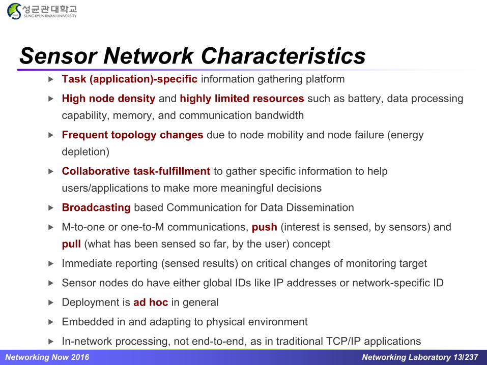
Sensor Network Characteristics Task (application)-specific information gathering platform
High node density and highly limited resources such as battery, data processing
capability, memory, and communication bandwidth
Frequent topology changes due to node mobility and node failure (energy
depletion)
Collaborative task-fulfillment to gather specific information to help
users/applications to make more meaningful decisions
Broadcasting based Communication for Data Dissemination
M-to-one or one-to-M communications, push (interest is sensed, by sensors) and
pull (what has been sensed so far, by the user) concept
Immediate reporting (sensed results) on critical changes of monitoring target
Sensor nodes do have either global IDs like IP addresses or network-specific ID
Deployment is ad hoc in general
Embedded in and adapting to physical environment
In-network processing, not end-to-end, as in traditional TCP/IP applications

Networking Now 2016 Networking Laboratory 14/237
Sensor Network Applications
Civil structural monitoring
Habitat/ecosystem monitoring
Agricultural maintenance networks
Environmental monitoring
Traffic/Vehicle Monitoring
Military security/alerting networks
Chemical Detection
Target Detection/Tracking
Smart homes
Human Health Monitoring
Robotic sensor networks
Circulatory Net

Networking Now 2016 Networking Laboratory 15/237
Applications (cont’d)

Networking Now 2016 Networking Laboratory 16/237
Applications (cont’d)

Networking Now 2016 Networking Laboratory 17/237
Flooding / Broadcasting

Networking Now 2016 Networking Laboratory 18/237
Flooding Schemes
Flooding is an indispensable
operation for providing control or
routing functionalities
However, naive broadcasting
causes severe redundant
transmissions, congestion of the
wireless media and collisions in
networks
We need efficient flooding schemes Flooding and Routing

Networking Now 2016 Networking Laboratory 19/237
Efficient Flooding Scheme using 1-Hop
Information*
Assumptions:
All nodes in the network have the same transmission range R
Each node has a unique ID
The location information of each node can be obtained via GPS or
some distributed localization methods
A node needs to know the information of its direct neighbors,
including their IDs and their geographic locations.
[*] H. Liu, X. Jia, P. Wan, X. Liu and F. F. Yao, “A Distributed and Efficient Flooding Scheme Using 1-Hop Information in
Mobile Ad Hoc Networks,” IEEE Transactions on Parallel and Distributed System, vol. 18, no. 5, 2007

Networking Now 2016 Networking Laboratory 20/237
Efficient Flooding Scheme using 1-Hop
Information
Basic idea:
The source node computes a subset of its neighbors as forwarding
nodes and attaches the list to the message
Then, the source transmits the message
Every node receives the message checks if itself is in the
forwarding list:
If yes, it computes the next hop forwarding nodes and
transmits the message as the same way as the source
Otherwise, it drops the message

Networking Now 2016 Networking Laboratory 21/237
Efficient Flooding Scheme using 1-Hop
Information: Computing Forwarding Set
Only having 1-hop neighbor information, to achieve 100%
deliverability, the coverage area of s’s forwarding set F(s) must cover
the entire neighbor’s coverage area of s
vv
uuss ww
Task
Every node in F(s) must contribute to
the boundary of s’s neighbor
coverage area
For example, s is the flooding source
and s’s neighbor set N(s) = { u, v, w }
In this case, F(s) = { s, v, u } because
the coverage area of w is covered by
the coverage areas of s, v, and u
Coverage
Area of w
Coverage
Area of u
Coverage
Area of s
Coverage
Area of v
Networking Now 2016 Networking Laboratory 22/237
Efficient Flooding Scheme using 1-Hop
Information: Forwarding Node Optimization
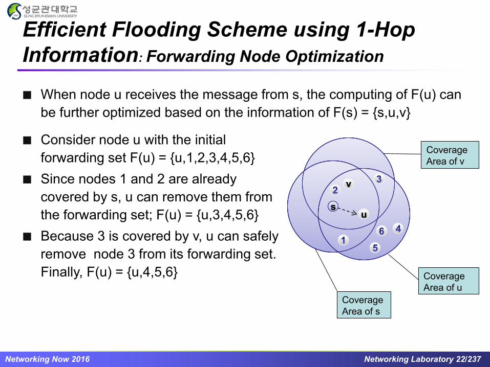
When node u receives the message from s, the computing of F(u) can
be further optimized based on the information of F(s) = {s,u,v}
vv
uuss
Consider node u with the initial
forwarding set F(u) = {u,1,2,3,4,5,6}
Since nodes 1 and 2 are already
covered by s, u can remove them from
the forwarding set; F(u) = {u,3,4,5,6}
Because 3 is covered by v, u can safely
remove node 3 from its forwarding set.
Finally, F(u) = {u,4,5,6} Coverage
Area of u
Coverage
Area of s
Coverage
Area of v
Networking Now 2016 Networking Laboratory 23/237
Efficient Flooding Scheme Exploiting 2-Hop
Backward Information*: Forwarding Set Optimization (1/3)
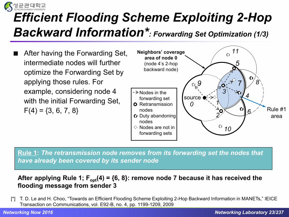
Rule 1: The retransmission node removes from its forwarding set the nodes that
have already been covered by its sender node
Rule 1: The retransmission node removes from its forwarding set the nodes that
have already been covered by its sender node
After applying Rule 1; Fopt(4) = {6, 8}: remove node 7 because it has received the
flooding message from sender 3
After having the Forwarding Set,
intermediate nodes will further
optimize the Forwarding Set by
applying those rules. For
example, considering node 4
with the initial Forwarding Set,
F(4) = {3, 6, 7, 8}2
5
4
Rule #1
area
3
6
87
0source
1
Neighbors’ coverage
area of node 0
(node 4’s 2-hop
backward node)
Nodes in the
forwarding set
Retransmission
nodes
Duty abandoning
nodes
Nodes are not in
forwarding sets
11
10
9
[*] T. D. Le and H. Choo, “Towards an Efficient Flooding Scheme Exploiting 2-Hop Backward Information in MANETs,” IEICE
Transaction on Communications, vol. E92-B, no. 4, pp. 1199-1209, 2009

Networking Now 2016 Networking Laboratory 24/237
Efficient Flooding Scheme Exploiting 2-Hop
Backward Information: Forwarding Set Optimization (2/3)
Rule 2: The retransmission node
that is closer to the sender removes
from its forwarding set the nodes
that are in the overlapping zones
Rule 2: The retransmission node
that is closer to the sender removes
from its forwarding set the nodes
that are in the overlapping zones
After applying Rule 2; Fopt(4) = {6}: remove node 8 because it is the neighbor of node 5
which is farther from sender node 3 than node 4
After applying Rule 1; Fopt(4) = {6, 8}
2
5
43
6
87
0source
1
Neighbors’ coverage
area of node 0
(node 4’s 2-hop
backward node)
Nodes in the
forwarding set
Retransmission
nodes
Duty abandoning
nodes
Nodes are not in
forwarding sets
11
10
9
Rule #2
area

Networking Now 2016 Networking Laboratory 25/237
Efficient Flooding Scheme Exploiting 2-Hop
Backward Information: Forwarding Set Optimization (3/3)
Rule 3: Based on the forwarding set
information of its 2-hop backward
node, the retransmission node
removes from the forwarding set the
nodes that are in the neighbors’
coverage area of the 2-hop
backward node
Rule 3: Based on the forwarding set
information of its 2-hop backward
node, the retransmission node
removes from the forwarding set the
nodes that are in the neighbors’
coverage area of the 2-hop
backward node
After applying Rule 2; Fopt(4) = {6}
After applying Rule 3; Fopt(4) = {}: remove node 6 because it is 1-hop neighbor of node 2
or 2-hop neighbor of node 0
Node 4 does not need to rebroadcast flooding messages
2
5
43
6
87
0source
1
Neighbors’ coverage
area of node 0
(node 4’s 2-hop
backward node)
Nodes in the
forwarding set
Retransmission
nodes
Duty abandoning
nodes
Nodes are not in
forwarding sets
11
10
9
Rule #3
area

Networking Now 2016 Networking Laboratory 26/237
Time To Live Sequence Based Expanding Rin
g Search (ERS)* (1/2)
Time To Live Sequence based Expanding Ring Search (ERS)
algorithm is a technique that can avoid network wide broadcasting by
searching a larger area around the source of broadcast
The source node send a query with a small
Time To Live (TTL) value (usually 1). Each
time the query is relayed by an intermediate
node, the TTL value is decreased by 1
If the TTL is greater than 0, the query will be
forwarded
Destination
S
D
RREQ: TTL = 1S
D
Source Node have route
to destination
[*] J. Hassan and S. Jha, “Optimising Expanding Ring Search for MultiHop Wireless Networks,” IEEE Global Telecommunications
Conference, Dallas, TX, 2004

Networking Now 2016 Networking Laboratory 27/237
If there is no reply within the time out period, the
source node increases the radius of the searching
ring by increasing the TTL
S
D
RREQ: TTL = 3
The searching process continues until
the information needed is found or the
TTL value reaches a threshold T
If the TTL reaches the threshold T, the
source starts a broadcast to the entire
network
S
D
Source
Destination
Node have route to
destination
Node in the 1st ring
Time To Live Sequence Based Expanding Rin
g Search (ERS) (2/2)
Networking Now 2016 Networking Laboratory 28/237
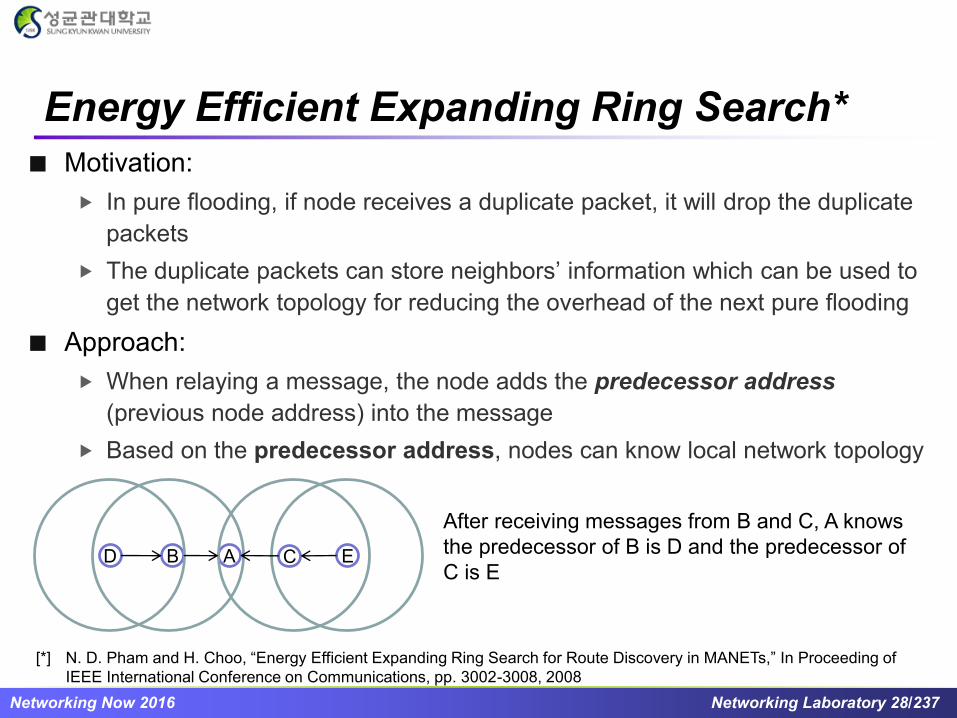
Energy Efficient Expanding Ring Search*
Motivation:
In pure flooding, if node receives a duplicate packet, it will drop the duplicate
packets
The duplicate packets can store neighbors’ information which can be used to
get the network topology for reducing the overhead of the next pure flooding
Approach:
When relaying a message, the node adds the predecessor address
(previous node address) into the message
Based on the predecessor address, nodes can know local network topology
A CBD E
After receiving messages from B and C, A knows
the predecessor of B is D and the predecessor of
C is E
[*] N. D. Pham and H. Choo, “Energy Efficient Expanding Ring Search for Route Discovery in MANETs,” In Proceeding of
IEEE International Conference on Communications, pp. 3002-3008, 2008
Networking Now 2016 Networking Laboratory 29/237
Energy Efficient Expanding Ring Search: Collecting local topology information (1/4)
O A
B
C
D
Relay: false
predAddr: A
Relay: false
predAddr: A
Relay: false
predAddr:
Relay: false
predAddr: A
Relay: false
predAddr:
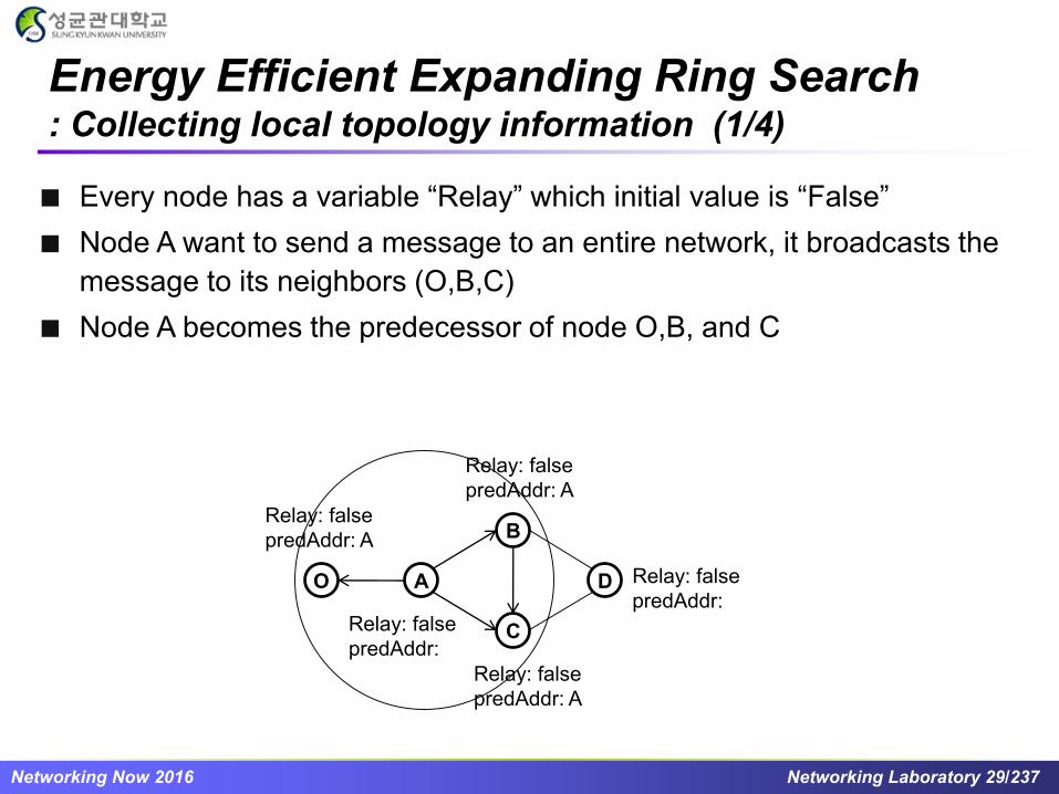
Every node has a variable “Relay” which initial value is “False”
Node A want to send a message to an entire network, it broadcasts the
message to its neighbors (O,B,C)
Node A becomes the predecessor of node O,B, and C

Networking Now 2016 Networking Laboratory 30/237
Energy Efficient Expanding Ring Search: Collecting local topology information (2/4)
Assume B firstly relays the message received from A.
D sets its “Predecessor Address” to B due to its first time receiving
A receives a duplicate message, and the predecessor address in the message
is A A sets “relay” to true
C receives a duplicate message, but the predecessor address in the message
is different from C C drops the message
O A
B
C
D
Relay: false
predAddr: A
Relay: false
predAddr: A
Relay: false
predAddr: B
Relay: false
predAddr: A
Relay: true
predAddr:
Networking Now 2016 Networking Laboratory 31/237
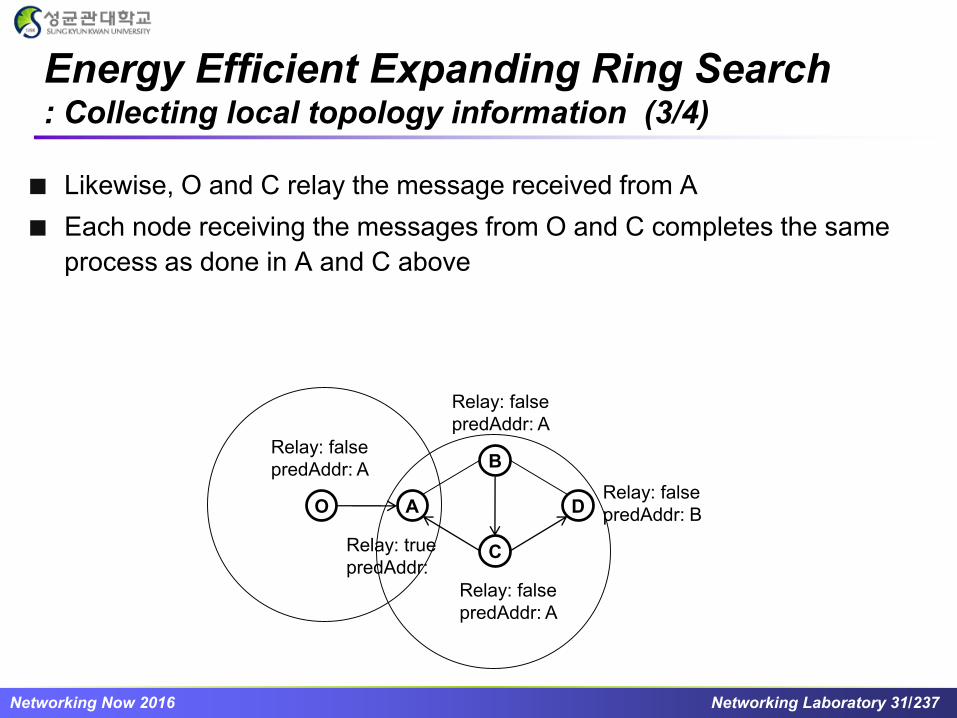
Energy Efficient Expanding Ring Search: Collecting local topology information (3/4)
Likewise, O and C relay the message received from A
Each node receiving the messages from O and C completes the same
process as done in A and C above
O A
B
C
D
Relay: false
predAddr: A
Relay: false
predAddr: A
Relay: false
predAddr: B
Relay: false
predAddr: A
Relay: true
predAddr:

Networking Now 2016 Networking Laboratory 32/237
Energy Efficient Expanding Ring Search: Collecting local topology information (4/4)
Finally, D relays the message received from B
B overhears the message, obtains the predecessor address and
compares to its address. They are the same B sets its “relay” to true
O A
B
C
D
Relay: false
predAddr: A
Relay: true
predAddr: A
Relay: false
predAddr: B
Relay: false
predAddr: A
Relay: true
predAddr:

Networking Now 2016 Networking Laboratory 33/237
Energy Efficient Expanding Ring Search: Reducing the overhead of pure flooding
After a pure flooding of A, assume that O wants to send a message to
the entire network
Only the nodes that have the variable “relay” set to true can relay the
message from O
O A
B
C
D
Relay: false
predAddr: A
Relay: true
predAddr: A
Relay: false
predAddr: B
Relay: false
predAddr: A
Relay: true
predAddr:

Networking Now 2016 Networking Laboratory 34/237
Duty Cycle Aware Broadcast* (1/5)
In WSNs, the lifetime of a sensor node is limited due to battery capacity
duty cycle (Sleep/Awake scheduling) is an effective strategy to save
energy
In duty cycle WSNs, due to intermittent connections between sensors,
a node needs to broadcast the message several times to cover all its
direct neighbors
sleepactive
S
B
C
D
B
C
D
Network topology
t2t0 t4 t6 t8
Working schedule
S has to broadcast 3 times
at t3, t5, t7
[*] F.Wang, J.Liu, “Duty-Cycle-Aware Broadcast in Wireless Sensor Networks,” INFOCOM, 2009
Networking Now 2016 Networking Laboratory 35/237
Duty Cycle Aware Broadcast (2/5)
For broadcasting in duty cycle WSNs, there is a trade off between the
number of broadcast messages and delay time
Based on the working schedule, the authors used the Time Coverage
graph to find a broadcast schedule that balances the number of
broadcast messages and delay time
We call a node is covered if it has received the message. The
coverage set S at time slot t contains all the nodes which have
received the message at t

Networking Now 2016 Networking Laboratory 36/237
Duty Cycle Aware Broadcast (3/5)
Time-Coverage Graph
…
time
CovSet
…
…
…
… … …
…
… … … …
{s}
t0
{s}t0+1
{s}t0+2
{s}t0+j
{s,n1}
t0
{s,n1}
t0+1
{s,n1}
t0+2
{s,n1}
t0+j
{.,s,.}
t0
{.,s,.}
t0+1
{.,s,.}
t0+2
{.,s,.}
t0+j
{1,..,s,
..,n}
t0
{1,..,s,
..,n}
t0+1
{1,..,s,
..,n}
t0+2
{1,..,s,
..,n}
t0+j
Time edge
Forwarding edge
There are many paths toward
the last row

Networking Now 2016 Networking Laboratory 37/237
Duty Cycle Aware Broadcast (4/5)
There are 2 types of edges in Time-Coverage graph:
Time edge: all nodes in the coverage set wait until the next time
slot
Forward edge: some nodes in the coverage set S broadcast the
message and leads to another coverage set S’.
a) Time edge b) Forward edge
w
w
w: weight of the edge
<S, t> <S, t +1>
<S, t >
<S’ ,t+1>

Networking Now 2016 Networking Laboratory 38/237
Duty Cycle Aware Broadcast (5/5)

Networking Now 2016 Networking Laboratory 39/237
Practice Problems
Give some important characteristics of the wireless sensor
networks
What is the key idea in using 1-hop neighbor information to
achieve efficient flooding?

Networking Now 2016 Networking Laboratory 40/237
Routing
in Wireless Ad Hoc Networks

Networking Now 2016 Networking Laboratory 41/237
Reactive Routing Protocols: Introduction (1/2)
Also called "on-demand" routing protocols
Routing paths are searched only when needed
A route discovery operation invokes a route-determination
procedure
This procedure terminates either when a route has been
found or no route available after examination for all route
permutations
In a mobile ad hoc network, active routes may be
disconnected due to node mobility
Route maintenance is an important operation of reactive routing
protocols

Networking Now 2016 Networking Laboratory 42/237
Reactive Routing Protocols: Introduction (2/2)
Pros and Cons:
Less control overhead compared to proactive routing protocols
Source nodes may suffer from long delays for route searching
before they can forward data packets
Reactive routing schemes/protocols
Dynamic Source Routing (DSR)
Ad Hoc On-Demand Distance Vector Routing (AODV)
Temporally-Ordered Routing Algorithm (TORA)

Networking Now 2016 Networking Laboratory 43/237
Reactive Routing Protocols: References
[1] Dynamic Source Routing (DSR),
http://tools.ietf.org/html/rfc4728
[2] Ad Hoc On-Demand Distance Vector Routing (AODV),
https://tools.ietf.org/html/rfc3561
[3] V. D. Park and M. S. Corson, "A highly adaptive distributed
routing algorithm for mobile wireless networks," IEEE
INFOCOM, vol. 3, pp.1405-1413, 1997. (TORA)

Networking Now 2016 Networking Laboratory 44/237
Dynamic Source Routing (DSR)*
When node S wants to send a packet to node D, but does
not know a route to D, node S initiates a route discovery
Source node S floods Route Request (RREQ)
Each node appends its own identifier when forwarding
RREQ
[*] Dynamic Source Routing (DSR), http://tools.ietf.org/html/rfc4728

Networking Now 2016 Networking Laboratory 45/237
S
Dynamic Source Routing (DSR) : Route Discovery (1/2)
B
A
E
F
H
J
D
C
G
I
K
M
N
L
[S][S,E]
[S,E,F]
[S,E,F,J]
Represents transmission of RREQ
[X,Y] Represents list of identifiers appended to RREQ

Networking Now 2016 Networking Laboratory 46/237
Dynamic Source Routing (DSR) : Route Discovery (2/2)
Destination D on receiving the first RREQ, sends a Route
Reply (RREP)
RREP is sent on a route obtained by reversing the route
appended to received RREQ
RREP includes the route from S to D on which RREQ was
received by node D

Networking Now 2016 Networking Laboratory 47/237
S
Dynamic Source Routing (DSR) : Route Reply (1/2)
Represents RREP control message
B
A
E
F
H
J
D
C
G
I
K
M
N
L
RREP [S,E,F,J,D]

Networking Now 2016 Networking Laboratory 48/237
Dynamic Source Routing (DSR) : Route Reply (2/2)
Route Reply can be sent by reversing the route in Route
Request (RREQ) only if links are guaranteed to be bi-
directional
► To ensure this, RREQ should be forwarded only if it is received on
a bi-directional link
If unidirectional (asymmetric) links are allowed, then RREP
may need a route discovery for S from node D
► Unless node D already knows a route to node S
► If a route discovery is initiated by D for a route to S, then the Route
Reply is piggybacked on the Route Request from D
If IEEE 802.11 MAC is used to send data, then links have
to be bi-directional (since Ack is used)

Networking Now 2016 Networking Laboratory 49/237
Dynamic Source Routing (DSR) : Sending data
Node S on receiving RREP, caches the route included in
the RREP
When node S sends a data packet to D, the entire route is
included in the packet header
► Hence the name is source routing
Intermediate nodes use the source route included in a
packet to determine to whom a packet should be
forwarded

Networking Now 2016 Networking Laboratory 50/237
Ad Hoc On-Demand Distance Vector
Routing (AODV)*
DSR includes source routes in packet headers
Resulting large headers can sometimes degrade performance► Particularly when data contents of a packet are small
AODV attempts to improve DSR by maintaining routing tables at the
nodes, so that data packets do not have to contain routes
AODV retains the desirable feature of DSR that routes are maintained
only between nodes which need to communicate
[*] Ad Hoc On-Demand Distance Vector Routing (AODV), https://tools.ietf.org/html/rfc3561

Networking Now 2016 Networking Laboratory 51/237
Ad Hoc On-Demand Distance Vector
Routing (AODV)
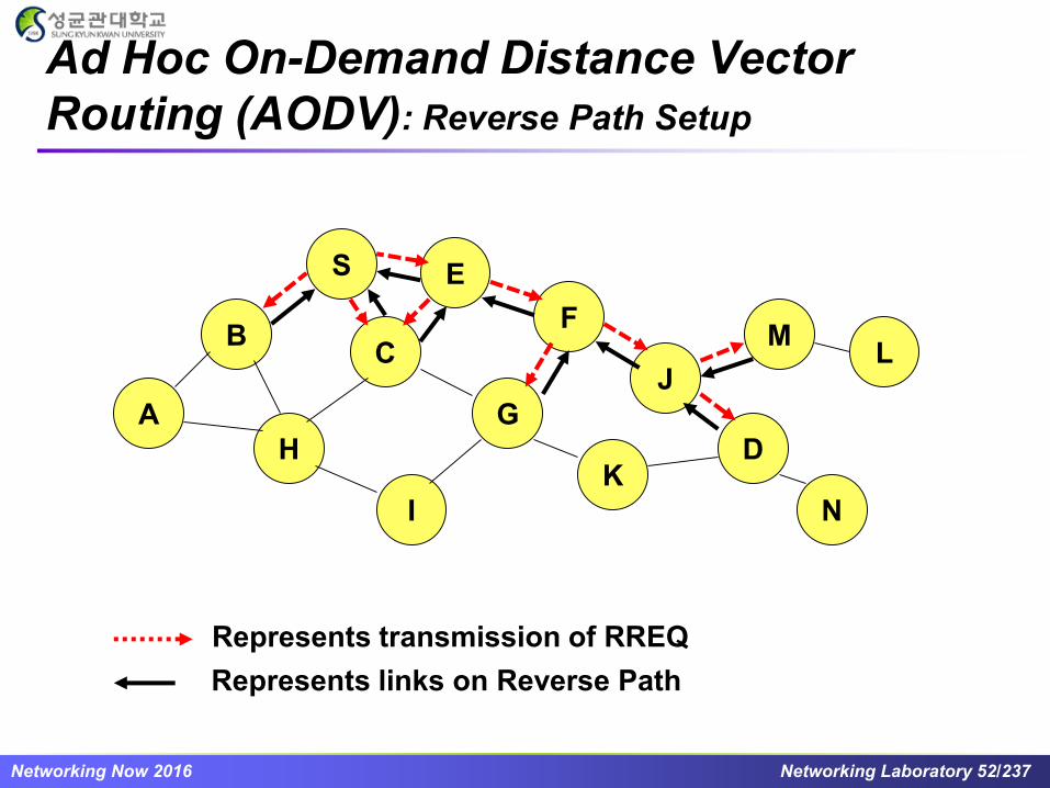
Route Requests (RREQ) are forwarded in a manner similar to DSR
When a node re-broadcasts a Route Request, it sets up a reverse path
pointing towards the source► AODV assumes symmetric (bi-directional) links
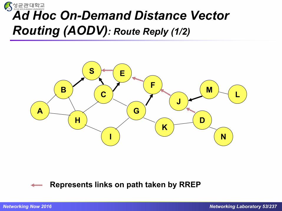
When the intended destination receives a Route Request, it replies by
sending a Route Reply
Route Reply travels along the reverse path set-up when Route
Request is forwarded
Networking Now 2016 Networking Laboratory 52/237
Ad Hoc On-Demand Distance Vector
Routing (AODV): Reverse Path Setup
S
B
A
E
F
H
J
D
C
G
I
K
M
N
L
Represents transmission of RREQ
Represents links on Reverse Path
Networking Now 2016 Networking Laboratory 53/237
Ad Hoc On-Demand Distance Vector
Routing (AODV): Route Reply (1/2)
S
B
A
E
F
H
J
D
C
G
I
K
M
N
L
Represents links on path taken by RREP

Networking Now 2016 Networking Laboratory 54/237
Ad Hoc On-Demand Distance Vector
Routing (AODV): Route Reply (2/2)
An intermediate node (not the destination) may also send a Route
Reply (RREP) provided that it knows a more recent path than the one
previously known to sender S
To determine whether the path known to an intermediate node is more
recent, destination sequence numbers are used
The likelihood that an intermediate node will send a Route Reply when
using AODV not as high as DSR► A new Route Request by node S for a destination is assigned a higher destination sequence
number. An intermediate node which knows a route, but with a smaller sequence number,
cannot send Route Reply

Networking Now 2016 Networking Laboratory 55/237
Ad Hoc On-Demand Distance Vector
Routing (AODV): Forward Path Setup
S
B
A
E
F
H
J
D
C
G
I
K
M
N
L
Forward links are setup when RREP travels along
the reverse path
Represents a link on the forward path

Networking Now 2016 Networking Laboratory 56/237
Partial Reversal Method (1/6)
A FB
C E G
D
Maintain a directed acyclic
graph (DAG) for each
destination, with the destination
being the only sink
This DAG is for destination
node D
Links are bi-directional
But algorithm imposes
logical directions on them
Networking Now 2016 Networking Laboratory 57/237
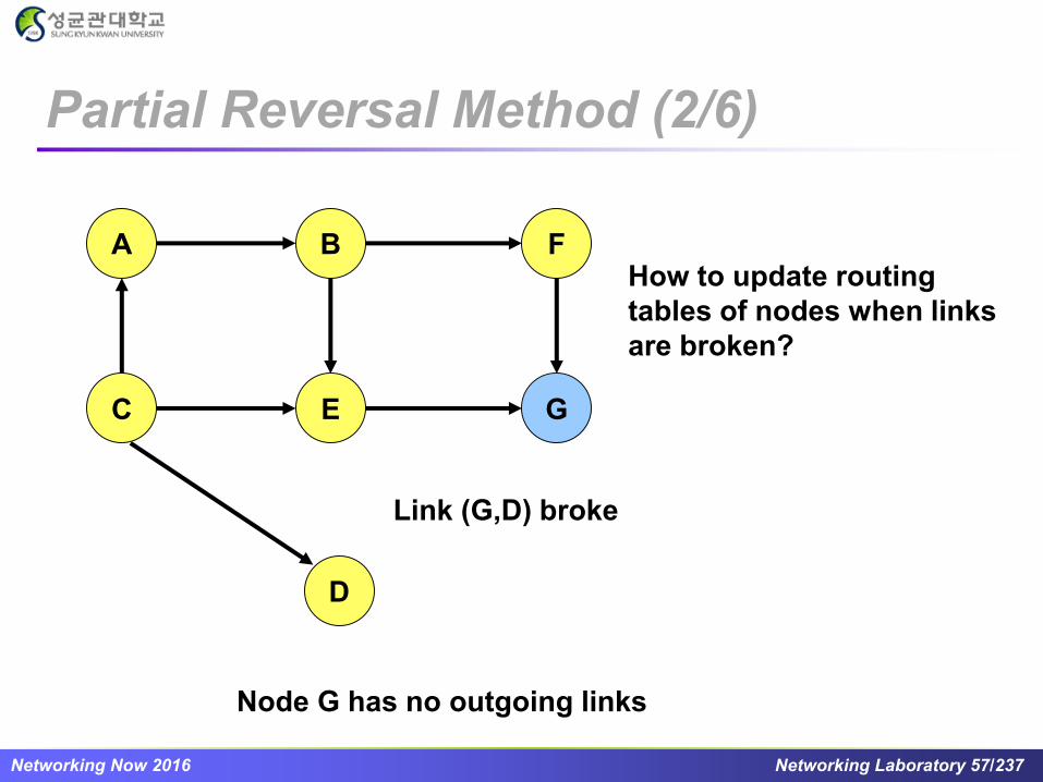
Partial Reversal Method (2/6)
Link (G,D) broke
A FB
C E G
D
Node G has no outgoing links
How to update routing
tables of nodes when links
are broken?
Networking Now 2016 Networking Laboratory 58/237
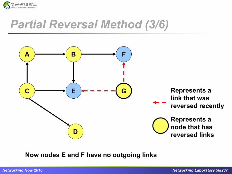
Partial Reversal Method (3/6)
A FB
C E G
D
Now nodes E and F have no outgoing links
Represents a
link that was
reversed recently
Represents a
node that has
reversed links

Networking Now 2016 Networking Laboratory 59/237
Partial Reversal Method (4/6)
A FB
C E G
D
Represents a
link that was
reversed recently
Networking Now 2016 Networking Laboratory 60/237
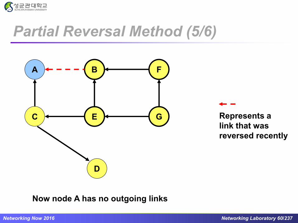
Partial Reversal Method (5/6)
A FB
C E G
D
Now node A has no outgoing links
Represents a
link that was
reversed recently

Networking Now 2016 Networking Laboratory 61/237
Partial Reversal Method (6/6)
A FB
C E G
D
Now all nodes (except destination D) have outgoing links
Thus, DAG has been restored with only the destination as a sink
Represents a
link that was
reversed recently
Networking Now 2016 Networking Laboratory 62/237
Temporally-Ordered Routing
Algorithm (TORA) (1/9)
If network is partitioned, link reversals continue
indefinitely
TORA modifies the partial link reversal method to be
able to detect partitions
When a partition is detected, all nodes in the partition
are informed, and link reversals in that partition cease
[*] V. D. Park and M. S. Corson, "A highly adaptive distributed routing algorithm for mobile wireless networks," IEEE INFOCOM,
vol. 3, pp.1405-1413, 1997.

Networking Now 2016 Networking Laboratory 63/237
A
B
E
D
F
C
DAG for
destination D
Temporally-Ordered Routing
Algorithm (TORA) (2/9)

Networking Now 2016 Networking Laboratory 64/237
A
B
E
D
F
C
TORA uses a
modified partial
reversal method
Node A has no outgoing links
Temporally-Ordered Routing
Algorithm (TORA) (3/9)

Networking Now 2016 Networking Laboratory 65/237
A
B
E
D
F
C
TORA uses a
modified partial
reversal method
Node B has no outgoing links
Temporally-Ordered Routing
Algorithm (TORA) (4/9)

Networking Now 2016 Networking Laboratory 66/237
A
B
E
D
F
C
Node B has no outgoing links
Temporally-Ordered Routing
Algorithm (TORA) (5/9)
Networking Now 2016 Networking Laboratory 67/237
A
B
E
D
F
C
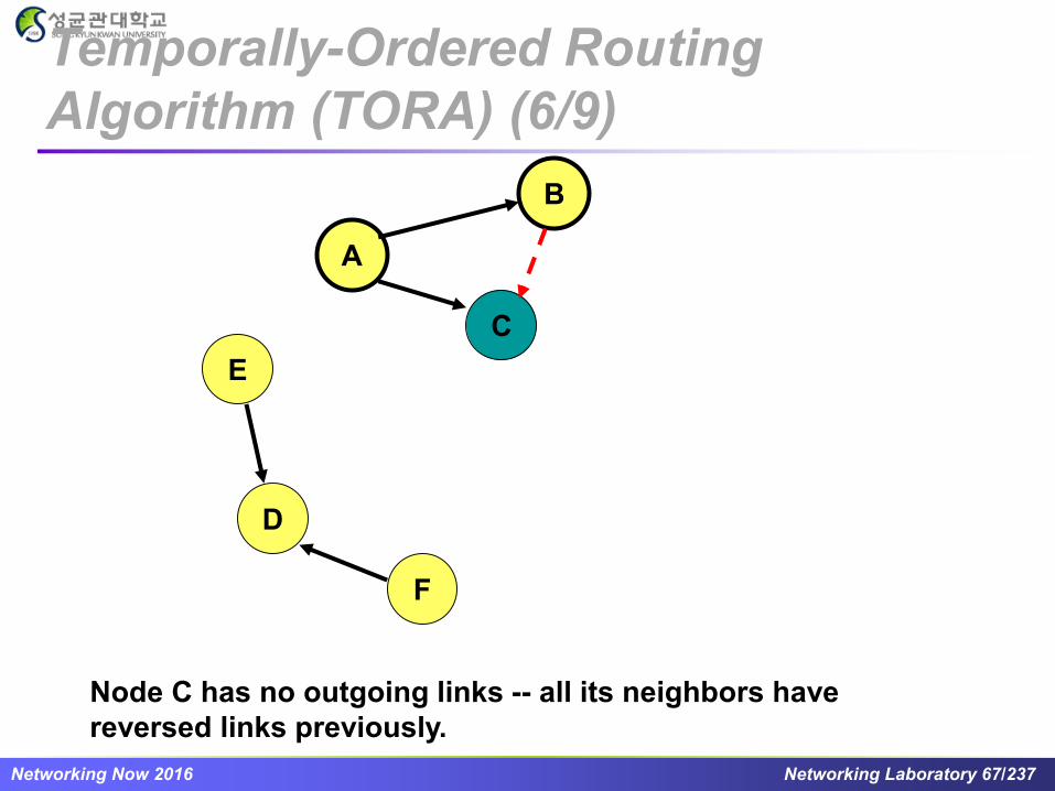
Node C has no outgoing links -- all its neighbors have
reversed links previously.
Temporally-Ordered Routing
Algorithm (TORA) (6/9)

Networking Now 2016 Networking Laboratory 68/237
A
B
E
D
F
C
Temporally-Ordered Routing
Algorithm (TORA) (7/9)

Networking Now 2016 Networking Laboratory 69/237
A
B
E
D
F
C
Node A has received the reflection from all its neighbors.
Node A determines that it is partitioned from destination D.
Node B propagates
the reflection to node A
Temporally-Ordered Routing
Algorithm (TORA) (8/9)

Networking Now 2016 Networking Laboratory 70/237
A
B
E
D
F
COn detecting a partition,
node A sends a clear (CLR)
message that purges all
directed links in that
partition
Temporally-Ordered Routing
Algorithm (TORA) (9/9)

Networking Now 2016 Networking Laboratory 71/237
Proactive Routing Protocols : Introduction (1/2)
Routes are calculated and stored in routing table in each
node before a node needs to find a path to destination
Routing information in all nodes is updated every time
There are two ways of updating the routing tables:
Event-driven: update messages are sent only when the network
topology changes
Cycle: update messages are sent throughout the network
periodically
Networking Now 2016 Networking Laboratory 72/237
Proactive Routing Protocols : Introduction (2/2)
Advantages
Slow latency
Suitable for real-time traffic
Disadvantages
Bandwidth may get wasted due to periodic updates
Slow reaction on restructuring and failures
Proactive routing schemes
Wireless Routing Protocol (WRP)
Distance Routing Effect Algorithm for Mobility (DREAM)
Destination Sequence Distance Vector (DSDV)
Fisheye State Routing (FSR)

Networking Now 2016 Networking Laboratory 73/237
Proactive Routing Protocols: References
[1] S. Murthy, J. J. Garcia-Luna-Aceves, "An efficient routing protocol
for wireless networks," Mobile Networks and Applications,
vol. 1(2), pp. 183–197, 1996. (WRP)
[2] S. Basagni, I. Chlamtac, V. Syrotiuk and B. WoodWard, “A
Distance Routing Effect Algorithm for Mobility (DREAM),”
MOBICOM, 1998.
[3] C. E. Perkins and P. Bhagwat, “Highly dynamic Destination-
Sequenced Distance-Vector Routing (DSDV) for mobile
computers,” SIGCOMM, 1994.
[4] G. Pei, M. Gerla and T.-W. Chen, “Fisheye State Routing in
Mobile Ad Hoc Networks,” ICDCS Workshops, 2000.

Networking Now 2016 Networking Laboratory 74/237
Wireless Routing Protocol*
Problem: Wireless Routing Protocol (WRP) is a proactive
unicast routing protocol for mobile ad-hoc networks
(MANET)
Goal: WRP is a table-based protocol with the goal of
maintaining routing information among all nodes in the
network
Motivation: WRP used an enhanced version of the
distance-vector routing protocol, which used the Bellman-
Ford algorithm to calculate paths
[*] S. Murthy, J. J. Garcia-Luna-Aceves, "An efficient routing protocol for wireless networks," Mobile
Networks and Applications, vol. 1(2), pp. 183–197, 1996.
Networking Now 2016 Networking Laboratory 75/237
Wireless Routing Protocol : Operation of WRP (1/4)
1
1
1
10
10
5(2,K)
(2,K)
(1,K)
(0,J)
K
I
J
B
Source node
Destination node
Normal node
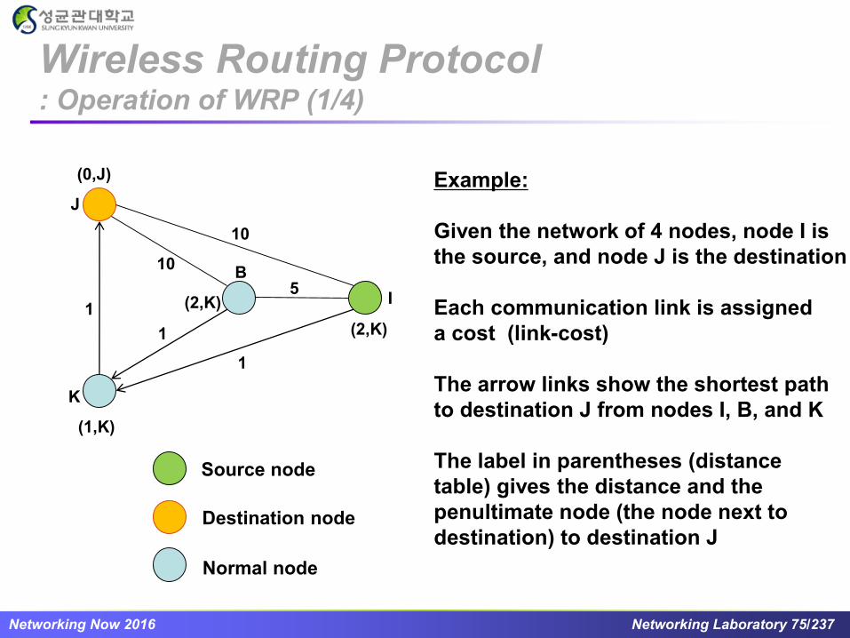
Example:
Given the network of 4 nodes, node I is
the source, and node J is the destination
Each communication link is assigned
a cost (link-cost)
The arrow links show the shortest path
to destination J from nodes I, B, and K
The label in parentheses (distance
table) gives the distance and the
penultimate node (the node next to
destination) to destination J

Networking Now 2016 Networking Laboratory 76/237
1
1
10
10
5(2,K)
(2,K)
(infinity, -)
(0,J)
K
I
J
B
Source node
Destination node
Normal node
Situation: Link KJ fails
Operation:
The distance table of node J does not
change, while the distance table of node
K is changed to (infinity, -)
Node K sends the update messages
to its neighbors (nodes B and I) to report
the infinity distance to destination J
Update message
Wireless Routing Protocol : Operation of WRP (2/4)

Networking Now 2016 Networking Laboratory 77/237
1
1
10
10
5(10,B)
(10,I)
(infinity, -)
(0,J)
K
I
J
B
Source node
Destination node
Normal node
Operation: (cont.)
Because nodes B and I know that node
K is the penultimate node to destination
J. They update their distance tables
Node B processes node K’s update and
select link BJ to destination J. Then, it
sends update message to its neighbors
When I gets node K’s update message, it
updates its distance table through node
K and checks for the possible path to
destination J through any other
neighboring nodes. This results in the
selection of link IJ to destination J. Then,
it sends update message to its neighborsUpdate message
Wireless Routing Protocol : Operation of WRP (3/4)
Networking Now 2016 Networking Laboratory 78/237
1
1
10
10
5(10,B)
(10,I)
(11, B)
(0,J)
K
I
J
B
Source node
Destination node
Normal node
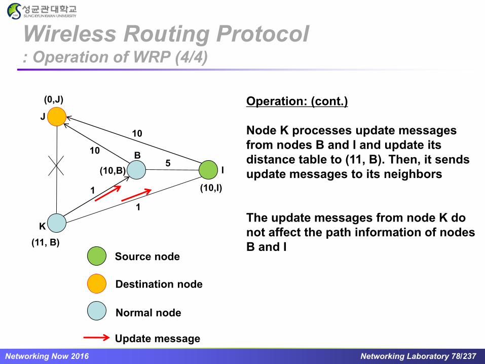
Operation: (cont.)
Node K processes update messages
from nodes B and I and update its
distance table to (11, B). Then, it sends
update messages to its neighbors
The update messages from node K do
not affect the path information of nodes
B and I
Update message
Wireless Routing Protocol : Operation of WRP (4/4)

Networking Now 2016 Networking Laboratory 79/237
Advantages
The novelty of WRP is in the way in which it achieves loop freedom
WRP involves fewer table updates than DSDV
Disadvantages
The complexity of maintenance of multiple tables demands a larger
memory, and greater processing power from nodes
Due to the control overhead, the protocol is not suitable for highly
dynamic and also for a large ad hoc wireless network
Wireless Routing Protocol : Properties

Networking Now 2016 Networking Laboratory 80/237
Distance Routing Effect Algorithm for
Mobility (DREAM)* (1/4)
Uses location and speed information of mobile nodes for
data packet routing
DREAM uses flooding of data packets as the routing
mechanism
► DREAM uses location information to limit the flood of data packets
to a small region
[*] S. Basagni, I. Chlamtac, V. Syrotiuk and B. WoodWard, “A Distance Routing Effect Algorithm for Mobility (DREAM),”
MOBICOM, 1998.

Networking Now 2016 Networking Laboratory 81/237
S
D
Expected zone
A
Node A, on receiving the
data packet, forwards it to
its neighbors within the
cone rooted at node A
S sends data packet to all
neighbors in the cone rooted
at node S
Distance Routing Effect Algorithm for
Mobility (DREAM) (2/4)

Networking Now 2016 Networking Laboratory 82/237
X
Y
r
X = last known location of node
D, at time t0
Y = location of node D at current
time t1, unknown to node S
r = (t1 - t0) * estimate of D’s speed
Expected Zone
Distance Routing Effect Algorithm for
Mobility (DREAM) (3/4)

Networking Now 2016 Networking Laboratory 83/237
Nodes periodically broadcast their physical location
Nearby nodes are updated more frequently, far away
nodes less frequently
Distance effect: Far away nodes seem to move at a lower
angular speed as compared to nearby nodes
Location update’s time-to-live field used to control how far
the information is propagated
Distance Routing Effect Algorithm for
Mobility (DREAM) (4/4)

Networking Now 2016 Networking Laboratory 84/237
Destination Sequence Distance Vector
(DSDV)* (1/5)
DSDV is based on the traditional Bellman-Ford algorithm
Each node maintains routing information for all known
destinations
Routing information must be updated periodically
Traffic overhead occurs even if there is no change in
network topology
[*] C. E. Perkins and P. Bhagwat, “Highly dynamic Destination-Sequenced Distance-Vector Routing (DSDV) for mobile computers,”
SIGCOMM, vol. 24, no.4, pp. 234–244, 1994.
Networking Now 2016 Networking Laboratory 85/237
Maintains routes which are never used
Keeps the simplicity of Distance Vector
Guarantees Loop Freeness by using Destination Sequence
Number
Allows fast reaction to topology changes
Making immediate route advertisement on significant changes in
routing table
But, waiting with advertising of unstable routes (damping
fluctuations)
Destination Sequence Distance Vector
(DSDV) (2/5)

Networking Now 2016 Networking Laboratory 86/237
Table entries
Metric: delay, number of hops, signal strength, etc.
Sequence number: originated from destination; ensures
loop freeness
Install Time: when entry was made (used to delete stale entries
from table)
Destination Next Metric Seq. Nr Install Time
A A 0 A-550 001000
B B 1 B-102 001200
C B 3 C-588 001200
D B 4 D-312 001200
Table Entries
Destination Sequence Distance Vector
(DSDV) (3/5)

Networking Now 2016 Networking Laboratory 87/237
Route Advertisements
Each node advertises its own routing information to its neighbors
Destination Address
Metric = Number of Hops to Destination
Destination Sequence Number
Rules for setting sequence number information are provided
On each advertisement, each node increases its own destination
sequence number (use only even numbers)
If a node is no longer reachable (timeout), its sequence number is
increased by 1 (odd sequence number) and the metric is set to infinite
Destination Sequence Distance Vector
(DSDV) (4/5)

Networking Now 2016 Networking Laboratory 88/237
Route Selection
Update information is compared to the current routing table
Selecting routes with higher destination sequence number (This ensure
s to use newest information from destination always)
Selecting routes with better metric when sequence numbers are equal
Destination Sequence Distance Vector
(DSDV) (5/5)
Networking Now 2016 Networking Laboratory 89/237
Fisheye State Routing (FSR)* (1/5)
FSR is similar to link state (LS) routing in that each node
maintains a view of the network topology with a cost for
each link
In LS routing, link state packets are flooded into the network
whenever a node detects a topology change
In FSR, nodes maintain a topology table (TT) based on the
up-to-date information received from neighboring nodes
and periodically exchange it with their local neighbors
[*] G. Pei, M. Gerla and T.-W. Chen, “Fisheye State Routing in Mobile Ad Hoc Networks,” ICDCS Workshops, 2000.

Networking Now 2016 Networking Laboratory 90/237
For large networks, in order to reduce the size of the routing
update messages the FSR technique uses different
exchange periods for different entries in the routing table
The network is divided in different scopes
Fisheye State Routing (FSR) (2/5)

Networking Now 2016 Networking Laboratory 91/237
“Fish-Eye”
Captures pixels near the focal point with more details
The detail decreases as the distance from the focal point increases
Maintains accurate information in immediate neighbors
Fisheye State Routing (FSR) (3/5)

Networking Now 2016 Networking Laboratory 92/237
Central node (red dot) has the most
accurate information about nodes in
white area and so on.
Parameters: Scope level/radius size
Fisheye State Routing (FSR) (4/5)

Networking Now 2016 Networking Laboratory 93/237
0
5
1
2
4
3
0:{1}
1:{0,2,3}
2:{5,1,4}
3:{1,4}
4:{5,2,3}
5:{2,4}
1
0
1
1
2
2
TT HOP
0:{1}
1:{0,2,3}
2:{5,1,4}
3:{1,4}
4:{5,2,3}
5:{2,4}
2
1
2
0
1
2
TT HOP
0:{1}
1:{0,2,3}
2:{5,1,4}
3:{1,4}
4:{5,2,3}
5:{2,4}
2
2
1
1
0
1
TT HOPEntries in black
are exchanged
more frequently
Message Reduction in FSR
Fisheye State Routing (FSR) (5/5)