netscatter: enabling large-scale backscatter networksnetscatter: enabling large-scale backscatter...
TRANSCRIPT
This paper is included in the Proceedings of the 16th USENIX Symposium on Networked Systems
Design and Implementation (NSDI ’19).February 26–28, 2019 • Boston, MA, USA
ISBN 978-1-931971-49-2
Open access to the Proceedings of the 16th USENIX Symposium on Networked Systems
Design and Implementation (NSDI ’19) is sponsored by
NetScatter: Enabling Large-Scale Backscatter Networks
Mehrdad Hessar, Ali Najafi, and Shyamnath Gollakota, University of Washington
https://www.usenix.org/conference/nsdi19/presentation/hessar
NetScatter: Enabling Large-Scale Backscatter Networks
Mehrdad Hessar†, Ali Najafi† and Shyamnath GollakotaUniversity of Washington
†Co-primary Student Authors
Abstract – We present the first wireless protocolthat scales to hundreds of concurrent transmissions frombackscatter devices. Our key innovation is a distributed cod-ing mechanism that works below the noise floor, operateson backscatter devices and can decode all the concurrenttransmissions at the receiver using a single FFT operation.Our design addresses practical issues such as timing and fre-quency synchronization as well as the near-far problem. Wedeploy our design using a testbed of backscatter hardwareand show that our protocol scales to concurrent transmis-sions from 256 devices using a bandwidth of only 500 kHz.Our results show throughput and latency improvements of14–62x and 15–67x over existing approaches and 1–2 ordersof magnitude higher transmission concurrency.
1 IntroductionThe last few years have seen rapid innovations in low-powerbackscatter communication [20, 31, 18, 15, 17, 21], culmi-nating in long range and reliable backscatter systems [26, 23,28]. These designs enable wireless devices to communicateat microwatts of power and operate reliably at long rangesto provide whole-home or warehouse coverage. To achievethis, they employ low-power coding techniques such as chirpspread spectrum, to decode weak backscatter signals belowthe noise floor [23, 26] and deliver long ranges.
While these long range backscatter systems are promis-ing for enabling power harvesting devices (e.g., solar andvibrations) as well as cheap and small Internet-connected de-vices that operate on button-cells or flexible printed batteries,they primarily work at the link layer and are not designedto scale with the number of devices — all these prior de-signs [26, 23, 28] are evaluated in a network of 1–2 devices.
Our goal in this paper is to design a network protocolthat enables these low-power backscatter networks to sup-port hundreds to thousands of concurrent transmissions. Thisis challenging because the resulting design must operate re-liably with weak backscatter signals that can be close to orbelow the noise floor. To this end, we present NetScatter, thefirst wireless protocol that can scale to hundreds and thou-
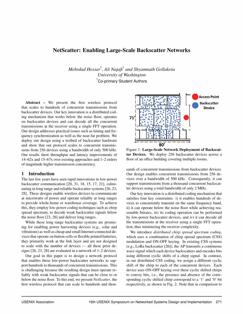
Figure 1: Large-Scale Network Deployment of Backscat-ter Devices. We deploy 256 backscatter devices across afloor of an office building covering multiple rooms.
sands of concurrent transmissions from backscatter devices.Our design enables concurrent transmissions from 256 de-vices over a bandwidth of 500 kHz. Consequently, it cansupport transmissions from a thousand concurrent backscat-ter devices using a total bandwidth of only 2 MHz.
Our key innovation is a distributed coding mechanism thatsatisfies four key constraints: i) it enables hundreds of de-vices to concurrently transmit on the same frequency band,ii) it can operate below the noise floor while achieving rea-sonable bitrates, iii) its coding operation can be performedby low-power backscatter devices, and iv) it can decode allthe transmissions at the receiver using a single FFT opera-tion, thus minimizing the receiver complexity.
We introduce distributed chirp spread spectrum coding,which uses a combination of chirp spread spectrum (CSS)modulation and ON-OFF keying. In existing CSS systems(e.g., LoRa backscatter [26]), the AP transmits a continuouswave signal which each device backscatters and encodes bitsusing different cyclic shifts of a chirp signal. In contrast,in our distributed CSS coding, we assign a different cyclicshift of the chirp to each of the concurrent devices. Eachdevice uses ON-OFF keying over these cyclic shifted chirpsto convey bits, i.e., the presence and absence of the corre-sponding cyclic shifted chirp correspond to a ‘1’ and ‘0’ bitrespectively, as shown in Fig. 2. Note that in comparison to
USENIX Association 16th USENIX Symposium on Networked Systems Design and Implementation 271
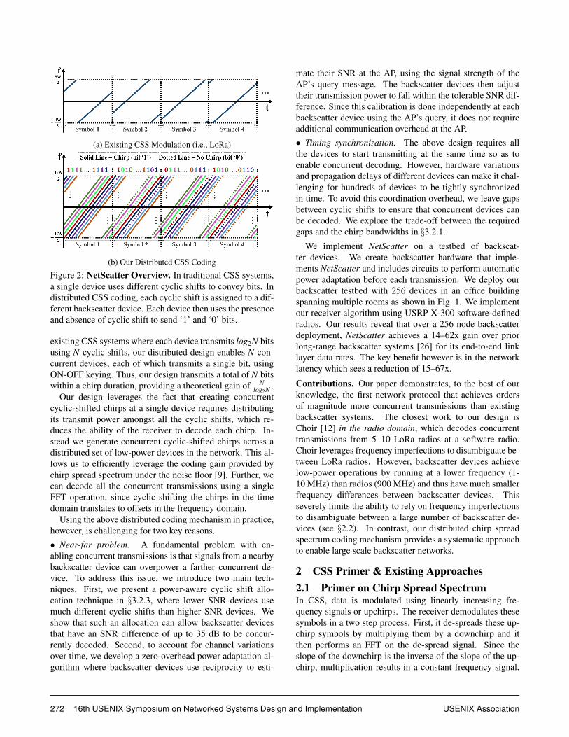
(a) Existing CSS Modulation (i.e., LoRa)
(b) Our Distributed CSS Coding
Figure 2: NetScatter Overview. In traditional CSS systems,a single device uses different cyclic shifts to convey bits. Indistributed CSS coding, each cyclic shift is assigned to a dif-ferent backscatter device. Each device then uses the presenceand absence of cyclic shift to send ‘1’ and ‘0’ bits.
existing CSS systems where each device transmits log2N bitsusing N cyclic shifts, our distributed design enables N con-current devices, each of which transmits a single bit, usingON-OFF keying. Thus, our design transmits a total of N bitswithin a chirp duration, providing a theoretical gain of N
log2N .Our design leverages the fact that creating concurrent
cyclic-shifted chirps at a single device requires distributingits transmit power amongst all the cyclic shifts, which re-duces the ability of the receiver to decode each chirp. In-stead we generate concurrent cyclic-shifted chirps across adistributed set of low-power devices in the network. This al-lows us to efficiently leverage the coding gain provided bychirp spread spectrum under the noise floor [9]. Further, wecan decode all the concurrent transmissions using a singleFFT operation, since cyclic shifting the chirps in the timedomain translates to offsets in the frequency domain.
Using the above distributed coding mechanism in practice,however, is challenging for two key reasons.
• Near-far problem. A fundamental problem with en-abling concurrent transmissions is that signals from a nearbybackscatter device can overpower a farther concurrent de-vice. To address this issue, we introduce two main tech-niques. First, we present a power-aware cyclic shift allo-cation technique in §3.2.3, where lower SNR devices usemuch different cyclic shifts than higher SNR devices. Weshow that such an allocation can allow backscatter devicesthat have an SNR difference of up to 35 dB to be concur-rently decoded. Second, to account for channel variationsover time, we develop a zero-overhead power adaptation al-gorithm where backscatter devices use reciprocity to esti-
mate their SNR at the AP, using the signal strength of theAP’s query message. The backscatter devices then adjusttheir transmission power to fall within the tolerable SNR dif-ference. Since this calibration is done independently at eachbackscatter device using the AP’s query, it does not requireadditional communication overhead at the AP.• Timing synchronization. The above design requires allthe devices to start transmitting at the same time so as toenable concurrent decoding. However, hardware variationsand propagation delays of different devices can make it chal-lenging for hundreds of devices to be tightly synchronizedin time. To avoid this coordination overhead, we leave gapsbetween cyclic shifts to ensure that concurrent devices canbe decoded. We explore the trade-off between the requiredgaps and the chirp bandwidths in §3.2.1.
We implement NetScatter on a testbed of backscat-ter devices. We create backscatter hardware that imple-ments NetScatter and includes circuits to perform automaticpower adaptation before each transmission. We deploy ourbackscatter testbed with 256 devices in an office buildingspanning multiple rooms as shown in Fig. 1. We implementour receiver algorithm using USRP X-300 software-definedradios. Our results reveal that over a 256 node backscatterdeployment, NetScatter achieves a 14–62x gain over priorlong-range backscatter systems [26] for its end-to-end linklayer data rates. The key benefit however is in the networklatency which sees a reduction of 15–67x.
Contributions. Our paper demonstrates, to the best of ourknowledge, the first network protocol that achieves ordersof magnitude more concurrent transmissions than existingbackscatter systems. The closest work to our design isChoir [12] in the radio domain, which decodes concurrenttransmissions from 5–10 LoRa radios at a software radio.Choir leverages frequency imperfections to disambiguate be-tween LoRa radios. However, backscatter devices achievelow-power operations by running at a lower frequency (1-10 MHz) than radios (900 MHz) and thus have much smallerfrequency differences between backscatter devices. Thisseverely limits the ability to rely on frequency imperfectionsto disambiguate between a large number of backscatter de-vices (see §2.2). In contrast, our distributed chirp spreadspectrum coding mechanism provides a systematic approachto enable large scale backscatter networks.
2 CSS Primer & Existing Approaches2.1 Primer on Chirp Spread SpectrumIn CSS, data is modulated using linearly increasing fre-quency signals or upchirps. The receiver demodulates thesesymbols in a two step process. First, it de-spreads these up-chirp symbols by multiplying them by a downchirp and itthen performs an FFT on the de-spread signal. Since theslope of the downchirp is the inverse of the slope of the up-chirp, multiplication results in a constant frequency signal,
272 16th USENIX Symposium on Networked Systems Design and Implementation USENIX Association
(a) (b) (c)
Figure 3: CSS Primer. We show upchirp and downchirpsymbols and FFT results of their multiplication. (a) Baselineupchirp symbol, (b) frequency shifted upchirp symbol and(c) cyclically shifted upchirp symbol.
as shown in Fig. 3(a). Thus, taking an FFT on this will leadto a peak in an associated FFT bin. Changing the initial fre-quency of an upchirp will result in a change in the demodu-lated signal’s FFT bin peak index which corresponds to theinitial change in frequency, as shown in Fig. 3(b). This prop-erty is used to convey information. When the sampling rateis equal to chirp bandwidth (BW), frequencies higher thanBW
2 will alias down to −BW2 as shown in Fig. 3(c). This means
cyclically shifting in time is equivalent to changing the initialfrequency and thus to conserve bandwidth, CSS uses cyclicshifts of the chirp in the time-domain instead of frequencyshifts. This means that to modulate the data we just need tocyclically shift the baseline upchirp in time. Note that onecan transmit multiple bits within each upchirp symbol. Inparticular, say the receiver performs an N point FFT. It candistinguish between N different cyclic shifts each of whichcorresponds to a peak in one of the N FFT bins. Thus, wecan transmit SF = log2N bits within each upchirp symbol,where SF is called the spreading factor.
Based on above explanations, CSS can be characterized bytwo parameters: chirp bandwidth/sampling rate and spread-ing factor. Thus, each chirp symbol duration is equal to 2SF
BWand the symbol rate is BW
2SF . Since CSS sends SF bits per sym-bol, the bitrate is equal to BW
2SF SF. This means increasing SFor decreasing BW decreases the bitrate. Further, the sensitiv-ity of the system depends on the symbol chirp duration andincreases with SF and decreases with BW.
2.2 Existing Collision ApproachesWhile existing CSS-based backscatter systems do not sup-port collision decoding, we outline potential approaches todeal with collisions in CSS radio systems, i.e. LoRa, andexplore whether they can be adopted for backscatter.
Using different spreading factors. One way to enable con-current transmissions is to assign different spreading factorsto each device. There are three problems with using multiplespreading factors in the same network: i) the receiver needsto use multiple FFTs and downchirps with different spread-ing factors to despread upchirp symbols of different devices,
0
0.2
0.4
0.6
0.8
1
0 0.5 1 1.5 2 2.5 3 3.5 4 4.5 5 5.5 6 6.5 7
CD
F
∆FFTBin
Backscatter Devices
LoRa Radios
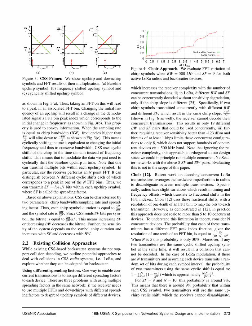
Figure 4: Choir Approach. We evaluate FFT variation ofchirp symbols when BW = 500 kHz and SF = 9 for bothactive LoRa radios and backscatter devices.
which increases the receiver complexity with the number ofconcurrent transmissions, ii) in LoRa, different BW and SFcan be concurrently decoded without sensitivity degradation,only if the chirp slope is different [25]. Specifically, if twochirp symbols transmitted concurrently with different BWand different SF, which result in the same chirp slope, BW2
SF(shown in Fig. 6 as well), the receiver cannot decode theirconcurrent transmissions. This results in only 19 differentBW and SF pairs that could be used concurrently, iii) fur-ther, requiring receiver sensitivity better than -123 dBm andbitrates of at least 1 kbps limits these concurrent configura-tions to only 8, which does not support hundreds of concur-rent devices on a 500 kHz band. Note that ignoring the re-ceiver complexity, this approach is orthogonal to our designsince we could in principle run multiple concurrent NetScat-ter networks with the above 8 SF and BW pairs. Evaluatingthis is not in the scope of this paper.
Choir [12]. Recent work on decoding concurrent LoRatransmissions leverages the hardware imperfections in radiosto disambiguate between multiple transmissions. Specifi-cally, radios have slight variations which result in timing andfrequency offsets, which translate to fractional shifts in theFFT indexes. Choir [12] uses these fractional shifts, with aresolution of one-tenth of an FFT bin, to map the bits to eachtransmitter. However, as demonstrated in [12], in practicethis approach does not scale to more than 5 to 10 concurrentdevices. To understand this limitation in theory, consider Nconcurrent devices. The probability that each of these trans-mitters has a different FFT peak index fraction, given theresolution of one-tenth of an FFT bin, is equal to 10!
(10−N)!10N .When N is 5 this probability is only 30%. Moreover, if anytwo transmitters use the same cyclic shifted upchirp sym-bol at the same time, it will result in a collision that can-not be decoded. In the case of LoRa modulation, if thereare N transmitters and assuming each device transmits a ran-dom set of bits during each symbol interval, the probabilityof two transmitters using the same cyclic shift is equal to:1−∏
Ni=1(1− i−1
2SF ) which is approximately N(N−1)2SF+1 .
For SF = 9 and N = 10, this probability is around 9%.This means that there is around 9% probability that withineach CSS symbol, two transmitters will use the same up-chirp cyclic shift, which the receiver cannot disambiguate.
USENIX Association 16th USENIX Symposium on Networked Systems Design and Implementation 273
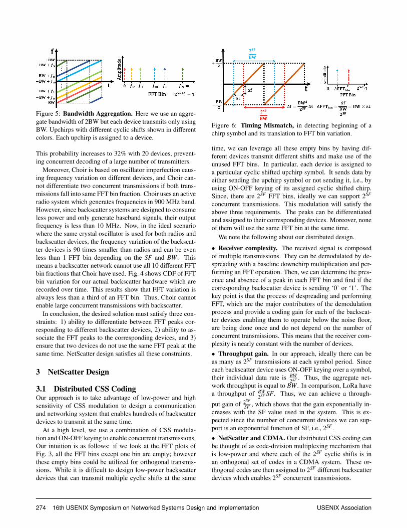
Figure 5: Bandwidth Aggregation. Here we use an aggre-gate bandwidth of 2BW but each device transmits only usingBW. Upchirps with different cyclic shifts shown in differentcolors. Each upchirp is assigned to a device.
This probability increases to 32% with 20 devices, prevent-ing concurrent decoding of a large number of transmitters.
Moreover, Choir is based on oscillator imperfection caus-ing frequency variation on different devices, and Choir can-not differentiate two concurrent transmissions if both trans-missions fall into same FFT bin fraction. Choir uses an activeradio system which generates frequencies in 900 MHz band.However, since backscatter systems are designed to consumeless power and only generate baseband signals, their outputfrequency is less than 10 MHz. Now, in the ideal scenariowhere the same crystal oscillator is used for both radios andbackscatter devices, the frequency variation of the backscat-ter devices is 90 times smaller than radios and can be evenless than 1 FFT bin depending on the SF and BW. Thismeans a backscatter network cannot use all 10 different FFTbin fractions that Choir have used. Fig. 4 shows CDF of FFTbin variation for our actual backscatter hardware which arerecorded over time. This results show that FFT variation isalways less than a third of an FFT bin. Thus, Choir cannotenable large concurrent transmissions with backscatter.
In conclusion, the desired solution must satisfy three con-straints: 1) ability to differentiate between FFT peaks cor-responding to different backscatter devices, 2) ability to as-sociate the FFT peaks to the corresponding devices, and 3)ensure that two devices do not use the same FFT peak at thesame time. NetScatter design satisfies all these constraints.
3 NetScatter Design
3.1 Distributed CSS CodingOur approach is to take advantage of low-power and highsensitivity of CSS modulation to design a communicationand networking system that enables hundreds of backscatterdevices to transmit at the same time.
At a high level, we use a combination of CSS modula-tion and ON-OFF keying to enable concurrent transmissions.Our intuition is as follows: if we look at the FFT plots ofFig. 3, all the FFT bins except one bin are empty; howeverthese empty bins could be utilized for orthogonal transmis-sions. While it is difficult to design low-power backscatterdevices that can transmit multiple cyclic shifts at the same
Figure 6: Timing Mismatch, in detecting beginning of achirp symbol and its translation to FFT bin variation.
time, we can leverage all these empty bins by having dif-ferent devices transmit different shifts and make use of theunused FFT bins. In particular, each device is assigned toa particular cyclic shifted upchirp symbol. It sends data byeither sending the upchirp symbol or not sending it, i.e., byusing ON-OFF keying of its assigned cyclic shifted chirp.Since, there are 2SF FFT bins, ideally we can support 2SF
concurrent transmissions. This modulation will satisfy theabove three requirements. The peaks can be differentiatedand assigned to their corresponding devices. Moreover, noneof them will use the same FFT bin at the same time.
We note the following about our distributed design.
• Receiver complexity. The received signal is composedof multiple transmissions. They can be demodulated by de-spreading with a baseline downchirp multiplication and per-forming an FFT operation. Then, we can determine the pres-ence and absence of a peak in each FFT bin and find if thecorresponding backscatter device is sending ‘0’ or ‘1’. Thekey point is that the process of despreading and performingFFT, which are the major contributors of the demodulationprocess and provide a coding gain for each of the backscat-ter devices enabling them to operate below the noise floor,are being done once and do not depend on the number ofconcurrent transmissions. This means that the receiver com-plexity is nearly constant with the number of devices.• Throughput gain. In our approach, ideally there can beas many as 2SF transmissions at each symbol period. Sinceeach backscatter device uses ON-OFF keying over a symbol,their individual data rate is BW
2SF . Thus, the aggregate net-work throughput is equal to BW. In comparison, LoRa havea throughput of BW
2SF SF. Thus, we can achieve a through-
put gain of 2SF
SF , which shows that the gain exponentially in-creases with the SF value used in the system. This is ex-pected since the number of concurrent devices we can sup-port is an exponential function of SF, i.e., 2SF .• NetScatter and CDMA. Our distributed CSS coding canbe thought of as code-division multiplexing mechanism thatis low-power and where each of the 2SF cyclic shifts is inan orthogonal set of codes in a CDMA system. These or-thogonal codes are then assigned to 2SF different backscatterdevices which enables 2SF concurrent transmissions.
274 16th USENIX Symposium on Networked Systems Design and Implementation USENIX Association

• Gain in the context of Shannon capacity. A key gainwe are achieving in our design stems from using the poweracross all the concurrent backscatter devices. Specificallywe note that the Shannon capacity of a multi-user networkthat operates under the noise floor linearly increases with thenumber of devices. Said differently, the multi-user capacityof an access point network is given as [27], C = BW log2(1+NPSPN
). Here BW is the channel bandwidth, PN and PS are thenoise and signal power and N is the number of concurrentdevices. At SNRs below the noise floor, the above equationcan be approximated as BW
ln(2)NPSPN
, since ln(1+ x) ≈ x whenx is small. This means that for systems that operate belowthe noise-floor, the network capacity scales linearly with thenumber of users. This linear increase stems from the fact thatthe N backscatter devices put in N times more power back tothe AP than a single backscatter device.• Bandwidth aggregation. The bitrate achieved by eachbackscatter device in our distributed design is given by BW
2SF
and the number of concurrent devices is 2SF . Thus, whilewe can increase the number of devices by increasing SF, itwould decrease the bitrate of each device. Thus, to increaseboth the bitrate and the number of device we should increasethe bandwidth, BW. Say, we want to support twice the num-ber of devices while maintaining the same bitrate by usingtwice the bandwidth. This can be achieved in two ways.First, we can use two filters and independently operate twosets of devices across the two bands. This approach requirestwo different FFTs to be performed independently across thebands. The second approach is to use one aggregate bandwith twice the bandwidth, 2BW, but use the same SF andchirp BW as before and alias down to −BW whenever thechirp frequency hits the maximum as shown in Fig. 5. Todemodulate this signal, we just need to multiply the signalwhich is composed of the aggregate band by the downchirpand perform 2×2SF FFT operation once. The complexity ofthis method is lower than the former since there is no need touse filters and separate the bands.
3.2 Addressing Practical Issues
3.2.1 Timing MismatchThe above design requires all the backscatter devices to betime synchronized. To understand why, consider two con-secutive upchirps being sent by a device, as shown in Fig. 6.Now say that we demodulate the signal in these two timingdurations, shown in blue and red, we will get different FFTpeak locations. Specifically, with a ∆t time difference be-tween these durations, the corresponding FFT bin peak loca-tion would change by, ∆FFTbin = ∆tBW. When this changeis greater than a single FFT bin, backscatter devices that areassigned to consecutive cyclic shifts interfere with each otherand cannot be decoded. Thus, all the devices should be timesynchronized. In our design the access point sends a querymessage telling devices to transmit concurrently. The de-
vices use this query to synchronize and respond concurrently.First, we explain the sources of time delay in our system andthen we explain our solutions. There are multiple factors thatcan contribute to time delays introduced in practice and canbe different for different backscatter devices.
• Hardware delay. Unlike Wi-Fi devices which use muchhigher clock frequencies for processors, backscatter devicesuse low-power microcontrollers (MCUs) that can introducea variable delay into the system. For backscatter devices,the source of these hardware delay variations come from thetime the envelope detector receives the query message fromthe access point, communicates it to the MCU and then thedevice backscatters the chirp signal. As we show in §4.2, thishardware delay variations can be as high as 3.5 µs, which cantranslate to more than one FFT bin at 500 kHz bandwidth.• Propagation delay and multipath. Since backscatter de-vices can be at different distances to the access point, theirtime of flight (TOF) can be different. However, since our tar-get application is for whole-home or warehouse sensing, thepropagation distance is less than 100 m which translates toa ToF < 666ns = 2×100
3×10⁸ and corresponds to only a 0.33 FFTbin change, assuming a bandwidth of 500 kHz. The multi-path delay spread for indoor environments is between 50 to300 ns [24, 11]. For 500 kHz, this delay spread translates toless than 0.15 FFT bin change, which is negligible.
Our solution: Bandwidth-based cyclic-shift assignment.Hardware delay variations over time are hard to correctfor. As described above, by nature of operating on MCUsand other low-power computational platforms, these deviceshave a hardware delay variation over time that changes be-tween packets. Our solution to this problem is to put a fewempty FFT bins adjacent to each FFT bin assigned to a de-vice. That is, if FFT bin i is assigned to a device, the adjacentSKIP−1 FFT bins are empty and not assigned to any device.This can be done by using only every SKIPth cyclic shift ofthe chirp. This ensures that the hardware delay does not re-sult in interference between adjacent devices.
Achieving such an assignment requires us to answer thefollowing key question: how do we pick the value SKIP?As described earlier, given the hardware delay variation ∆t,the shift in the number of FFT bins is ∆tBW. This meansthat there is a trade-off in our system regarding the total net-work throughput, bitrate for each device and sensitivity. Inparticular, increasing BW increases the number of FFT binsthat have to be left empty and decreases the total networkthroughput. On the other hand, decreasing BW reduces thenumber of FFT bins but decreases the bitrate per device withthe same SF. To compensate for the decreased device’s bi-trate, we can decrease the SF. Note that, we can choose totalbandwidth, chirp BW and SF of the system by consideringthe hardware delay variations, required bitrate per device,sensitivity for each device and total number of devices. Forour implementation, we pick the same total bandwidth and
USENIX Association 16th USENIX Symposium on Networked Systems Design and Implementation 275
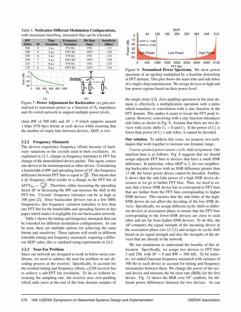
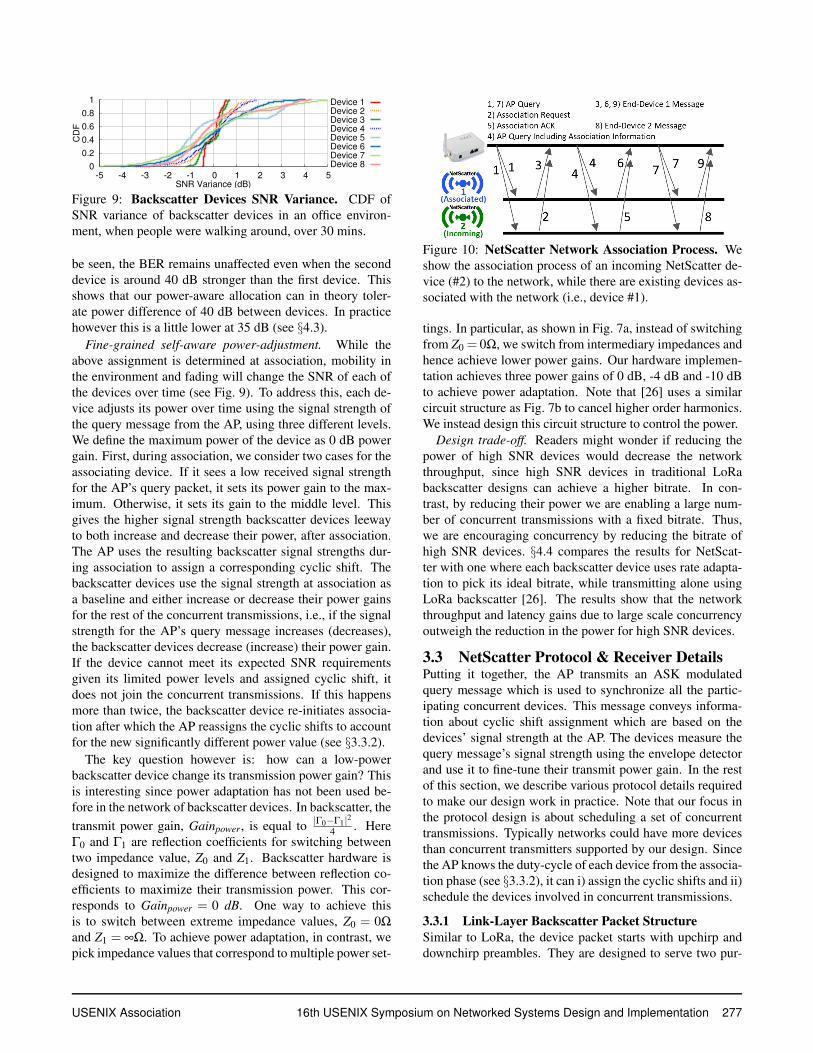
Table 1: NetScatter Different Modulation Configurations,with maximum time/freq. mismatch that can be tolerated.
BW[kHz] SF
TimeVariation
FrequencyVariation
Bit Rate[bps]
Sensitivity[dBm]
500 9 2 µs 976 Hz 976 -123500 8 2 µs 1953 Hz 1953 -120250 8 4 µs 976 Hz 976 -123250 7 4 µs 1953 Hz 1953 -120125 7 8 µs 976 Hz 976 -123125 6 8 µs 1953 Hz 1953 -118
-30
-20
-10
0
0 200 400 600 800 1000
Gain
(dB
)
Z0
(a) (b)Figure 7: Power Adjustment for Backscatter. (a) gain nor-malized to maximum power as a function of Z0 impedanceand (b) switch network to support multiple power levels.
chirp BW of 500 kHz and SF = 9 which supports around1 kbps (976 bps) bitrate at each device while ensuring thatthe number of empty bins between devices, SKIP, is two.
3.2.2 Frequency MismatchThe devices experience frequency offsets because of hard-ware variations in the crystals used in their oscillators. Asexplained in §2.1, change in frequency translates to FFT binchange of the demodulated device packet. This again, causesone device to be misinterpreted as other device. Consideringa bandwidth of BW and spreading factor of SF, the frequencydifference between FFT bins is equal to BW
2SF . This means thata ∆f frequency offset results in a change in the FFT bin of∆FFTbin =
2SF∆fBW . Therefore, either increasing the spreading
factor SF or decreasing the BW can increase the shift in theFFT bin. Crystals’ frequency tolerance can be as high as100 ppm [2]. Since backscatter devices run at a few MHzfrequencies, this frequency variation translates to less thanone FFT bin for the bandwidths and spreading factors in thispaper which makes it negligible for our backscatter network.
Table 1 shows the timing and frequency mismatch that canbe tolerated for different modulation configurations. As canbe seen, there are multiple options for achieving the samebitrate and sensitivity. These options will result in differenttolerable timing and frequency mismatch, requiring a differ-ent SKIP value; this is validated using experiments in §4.2.
3.2.3 Near-Far ProblemSince our network are designed to work in below-noise con-ditions, we need to address the near-far problem in our de-coding process at the receiver. Specifically, to account forthe residual timing and frequency offsets, a CSS receiver hasto achieve a sub-FFT bin resolution. To do so without in-creasing the sampling rate, the receiver uses zero-paddingwhich adds zeros at the end of the time domain samples of
-50
-40
-30
-20
-10
0
0 640 1280 1920 2560 3200 3840 4480 5120
0 64 128 192 256 320 384 448 512
Po
we
r (d
B)
FFT Bin
SKIP
High Power Low Power High Power
∗ (SKIP=2,-13dB)
∗ (SKIP=3,-21dB)
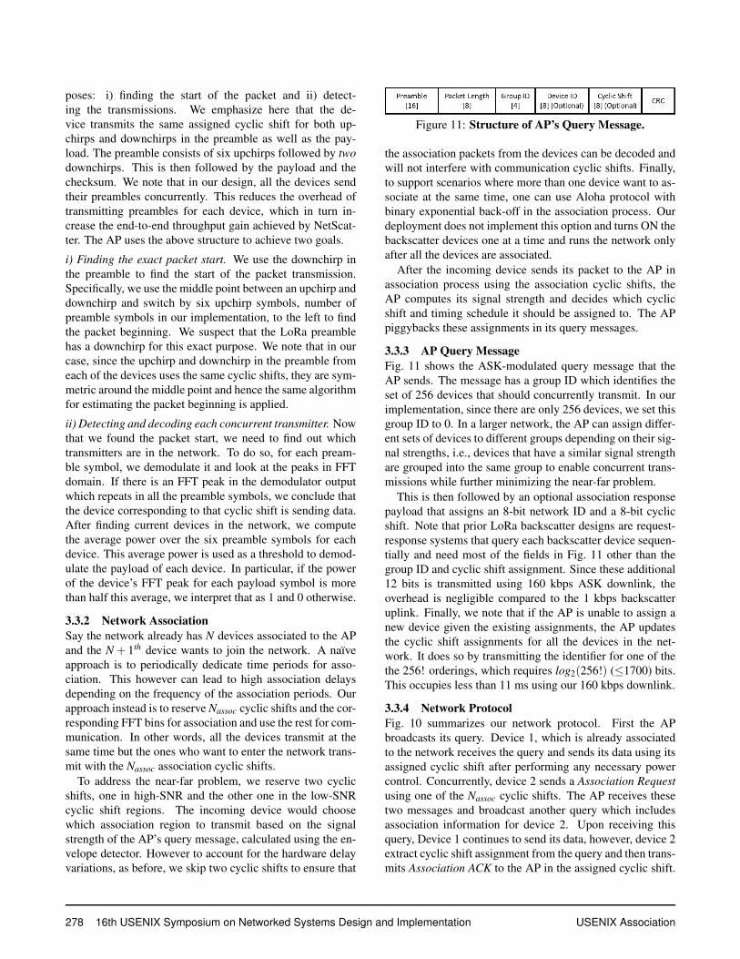
Figure 8: Normalized Power Spectrum. We show powerspectrum of an upchirp multiplied by a baseline downchirpin FFT domain. This plot shows the main lobe and side lobesof a single chirp transmission. We assign devices to high andlow power regions based on their power level.
the single chirp [12]. Zero-padding operation in the time do-main is effectively a multiplication operation with a pulsewhich translates to convolution with a sinc function in theFFT domain. This makes it easier to locate the FFT peak lo-cation. However, convolving with a sinc function introducesside lobes as shown in Fig. 8. Assume that there are two de-vices with cyclic shifts C1 = 0 and C2. If the power of C2 islower than power of C1’s side lobes, it cannot be decoded.
Our solution. To address this issue, we propose two tech-niques that work together to increase our dynamic range.
Coarse-grained power-aware cyclic shift assignment. Ourintuition here is as follows: Fig. 8 suggests that we shouldassign adjacent FFT bins to devices that have a small SNRdifference. In particular, when SKIP is 2, for two neighbor-ing backscatter devices with an SNR difference greater than13 dB, the lower power device cannot be decoded. Further,it shows that the side-lobe power of a high SNR device de-creases as we go to farther FFT bins. Thus, we need to en-sure that a lower SNR device has to correspond to FFT binsthat are farther from the FFT bins corresponding to higherSNR devices. This ensures that the side-lobes of the high-SNR device do not affect the decoding of the low-SNR de-vices. Specifically, we assign different cyclic shifts to differ-ent devices at association phase to ensure that the FFT binscorresponding to the lower-SNR devices are close to eachother and are far from higher-SNR devices. To do this, theAP computes the signal strength of the incoming device inthe association phase (see §3.3.2) and assigns its cyclic shiftbased on its signal strength and also the strengths of the de-vices that are already in the network.
We run simulations to understand the benefits of this al-location. Specifically, we assign two devices to FFT bins2 and 258, with SF = 9 and BW = 500 kHz. To be realis-tic, we added Gaussian frequency mismatch with variance of300 Hz to each device to account for timing and frequencymismatches between them. We change the power of the sec-ond device and measure the bit error rate (BER) for the firstdevice. Fig. 12 shows the BER over 104 symbols, for dif-ferent power differences between the two devices. As can
276 16th USENIX Symposium on Networked Systems Design and Implementation USENIX Association
0
0.2
0.4
0.6
0.8
1
-5 -4 -3 -2 -1 0 1 2 3 4 5
CD
F
SNR Variance (dB)
Device 1
Device 2
Device 3
Device 4
Device 5
Device 6
Device 7
Device 8
Figure 9: Backscatter Devices SNR Variance. CDF ofSNR variance of backscatter devices in an office environ-ment, when people were walking around, over 30 mins.
be seen, the BER remains unaffected even when the seconddevice is around 40 dB stronger than the first device. Thisshows that our power-aware allocation can in theory toler-ate power difference of 40 dB between devices. In practicehowever this is a little lower at 35 dB (see §4.3).
Fine-grained self-aware power-adjustment. While theabove assignment is determined at association, mobility inthe environment and fading will change the SNR of each ofthe devices over time (see Fig. 9). To address this, each de-vice adjusts its power over time using the signal strength ofthe query message from the AP, using three different levels.We define the maximum power of the device as 0 dB powergain. First, during association, we consider two cases for theassociating device. If it sees a low received signal strengthfor the AP’s query packet, it sets its power gain to the max-imum. Otherwise, it sets its gain to the middle level. Thisgives the higher signal strength backscatter devices leewayto both increase and decrease their power, after association.The AP uses the resulting backscatter signal strengths dur-ing association to assign a corresponding cyclic shift. Thebackscatter devices use the signal strength at association asa baseline and either increase or decrease their power gainsfor the rest of the concurrent transmissions, i.e., if the signalstrength for the AP’s query message increases (decreases),the backscatter devices decrease (increase) their power gain.If the device cannot meet its expected SNR requirementsgiven its limited power levels and assigned cyclic shift, itdoes not join the concurrent transmissions. If this happensmore than twice, the backscatter device re-initiates associa-tion after which the AP reassigns the cyclic shifts to accountfor the new significantly different power value (see §3.3.2).
The key question however is: how can a low-powerbackscatter device change its transmission power gain? Thisis interesting since power adaptation has not been used be-fore in the network of backscatter devices. In backscatter, thetransmit power gain, Gainpower, is equal to |Γ0−Γ1|2
4 . HereΓ0 and Γ1 are reflection coefficients for switching betweentwo impedance value, Z0 and Z1. Backscatter hardware isdesigned to maximize the difference between reflection co-efficients to maximize their transmission power. This cor-responds to Gainpower = 0 dB. One way to achieve thisis to switch between extreme impedance values, Z0 = 0Ω
and Z1 = ∞Ω. To achieve power adaptation, in contrast, wepick impedance values that correspond to multiple power set-
Figure 10: NetScatter Network Association Process. Weshow the association process of an incoming NetScatter de-vice (#2) to the network, while there are existing devices as-sociated with the network (i.e., device #1).
tings. In particular, as shown in Fig. 7a, instead of switchingfrom Z0 = 0Ω, we switch from intermediary impedances andhence achieve lower power gains. Our hardware implemen-tation achieves three power gains of 0 dB, -4 dB and -10 dBto achieve power adaptation. Note that [26] uses a similarcircuit structure as Fig. 7b to cancel higher order harmonics.We instead design this circuit structure to control the power.
Design trade-off. Readers might wonder if reducing thepower of high SNR devices would decrease the networkthroughput, since high SNR devices in traditional LoRabackscatter designs can achieve a higher bitrate. In con-trast, by reducing their power we are enabling a large num-ber of concurrent transmissions with a fixed bitrate. Thus,we are encouraging concurrency by reducing the bitrate ofhigh SNR devices. §4.4 compares the results for NetScat-ter with one where each backscatter device uses rate adapta-tion to pick its ideal bitrate, while transmitting alone usingLoRa backscatter [26]. The results show that the networkthroughput and latency gains due to large scale concurrencyoutweigh the reduction in the power for high SNR devices.
3.3 NetScatter Protocol & Receiver DetailsPutting it together, the AP transmits an ASK modulatedquery message which is used to synchronize all the partic-ipating concurrent devices. This message conveys informa-tion about cyclic shift assignment which are based on thedevices’ signal strength at the AP. The devices measure thequery message’s signal strength using the envelope detectorand use it to fine-tune their transmit power gain. In the restof this section, we describe various protocol details requiredto make our design work in practice. Note that our focus inthe protocol design is about scheduling a set of concurrenttransmissions. Typically networks could have more devicesthan concurrent transmitters supported by our design. Sincethe AP knows the duty-cycle of each device from the associa-tion phase (see §3.3.2), it can i) assign the cyclic shifts and ii)schedule the devices involved in concurrent transmissions.
3.3.1 Link-Layer Backscatter Packet StructureSimilar to LoRa, the device packet starts with upchirp anddownchirp preambles. They are designed to serve two pur-
USENIX Association 16th USENIX Symposium on Networked Systems Design and Implementation 277
poses: i) finding the start of the packet and ii) detect-ing the transmissions. We emphasize here that the de-vice transmits the same assigned cyclic shift for both up-chirps and downchirps in the preamble as well as the pay-load. The preamble consists of six upchirps followed by twodownchirps. This is then followed by the payload and thechecksum. We note that in our design, all the devices sendtheir preambles concurrently. This reduces the overhead oftransmitting preambles for each device, which in turn in-crease the end-to-end throughput gain achieved by NetScat-ter. The AP uses the above structure to achieve two goals.
i) Finding the exact packet start. We use the downchirp inthe preamble to find the start of the packet transmission.Specifically, we use the middle point between an upchirp anddownchirp and switch by six upchirp symbols, number ofpreamble symbols in our implementation, to the left to findthe packet beginning. We suspect that the LoRa preamblehas a downchirp for this exact purpose. We note that in ourcase, since the upchirp and downchirp in the preamble fromeach of the devices uses the same cyclic shifts, they are sym-metric around the middle point and hence the same algorithmfor estimating the packet beginning is applied.
ii) Detecting and decoding each concurrent transmitter. Nowthat we found the packet start, we need to find out whichtransmitters are in the network. To do so, for each pream-ble symbol, we demodulate it and look at the peaks in FFTdomain. If there is an FFT peak in the demodulator outputwhich repeats in all the preamble symbols, we conclude thatthe device corresponding to that cyclic shift is sending data.After finding current devices in the network, we computethe average power over the six preamble symbols for eachdevice. This average power is used as a threshold to demod-ulate the payload of each device. In particular, if the powerof the device’s FFT peak for each payload symbol is morethan half this average, we interpret that as 1 and 0 otherwise.
3.3.2 Network AssociationSay the network already has N devices associated to the APand the N + 1th device wants to join the network. A naıveapproach is to periodically dedicate time periods for asso-ciation. This however can lead to high association delaysdepending on the frequency of the association periods. Ourapproach instead is to reserve Nassoc cyclic shifts and the cor-responding FFT bins for association and use the rest for com-munication. In other words, all the devices transmit at thesame time but the ones who want to enter the network trans-mit with the Nassoc association cyclic shifts.
To address the near-far problem, we reserve two cyclicshifts, one in high-SNR and the other one in the low-SNRcyclic shift regions. The incoming device would choosewhich association region to transmit based on the signalstrength of the AP’s query message, calculated using the en-velope detector. However to account for the hardware delayvariations, as before, we skip two cyclic shifts to ensure that
Figure 11: Structure of AP’s Query Message.
the association packets from the devices can be decoded andwill not interfere with communication cyclic shifts. Finally,to support scenarios where more than one device want to as-sociate at the same time, one can use Aloha protocol withbinary exponential back-off in the association process. Ourdeployment does not implement this option and turns ON thebackscatter devices one at a time and runs the network onlyafter all the devices are associated.
After the incoming device sends its packet to the AP inassociation process using the association cyclic shifts, theAP computes its signal strength and decides which cyclicshift and timing schedule it should be assigned to. The APpiggybacks these assignments in its query messages.
3.3.3 AP Query MessageFig. 11 shows the ASK-modulated query message that theAP sends. The message has a group ID which identifies theset of 256 devices that should concurrently transmit. In ourimplementation, since there are only 256 devices, we set thisgroup ID to 0. In a larger network, the AP can assign differ-ent sets of devices to different groups depending on their sig-nal strengths, i.e., devices that have a similar signal strengthare grouped into the same group to enable concurrent trans-missions while further minimizing the near-far problem.
This is then followed by an optional association responsepayload that assigns an 8-bit network ID and a 8-bit cyclicshift. Note that prior LoRa backscatter designs are request-response systems that query each backscatter device sequen-tially and need most of the fields in Fig. 11 other than thegroup ID and cyclic shift assignment. Since these additional12 bits is transmitted using 160 kbps ASK downlink, theoverhead is negligible compared to the 1 kbps backscatteruplink. Finally, we note that if the AP is unable to assign anew device given the existing assignments, the AP updatesthe cyclic shift assignments for all the devices in the net-work. It does so by transmitting the identifier for one of thethe 256! orderings, which requires log2(256!) (≤1700) bits.This occupies less than 11 ms using our 160 kbps downlink.
3.3.4 Network ProtocolFig. 10 summarizes our network protocol. First the APbroadcasts its query. Device 1, which is already associatedto the network receives the query and sends its data using itsassigned cyclic shift after performing any necessary powercontrol. Concurrently, device 2 sends a Association Requestusing one of the Nassoc cyclic shifts. The AP receives thesetwo messages and broadcast another query which includesassociation information for device 2. Upon receiving thisquery, Device 1 continues to send its data, however, device 2extract cyclic shift assignment from the query and then trans-mits Association ACK to the AP in the assigned cyclic shift.
278 16th USENIX Symposium on Networked Systems Design and Implementation USENIX Association
0.0001
0.001
0.01
0.1
1
-20 -18 -16 -14 -12 -10
BE
R
SNR (dB)
One Backscatter Device 35 dB 40 dB 45 dB
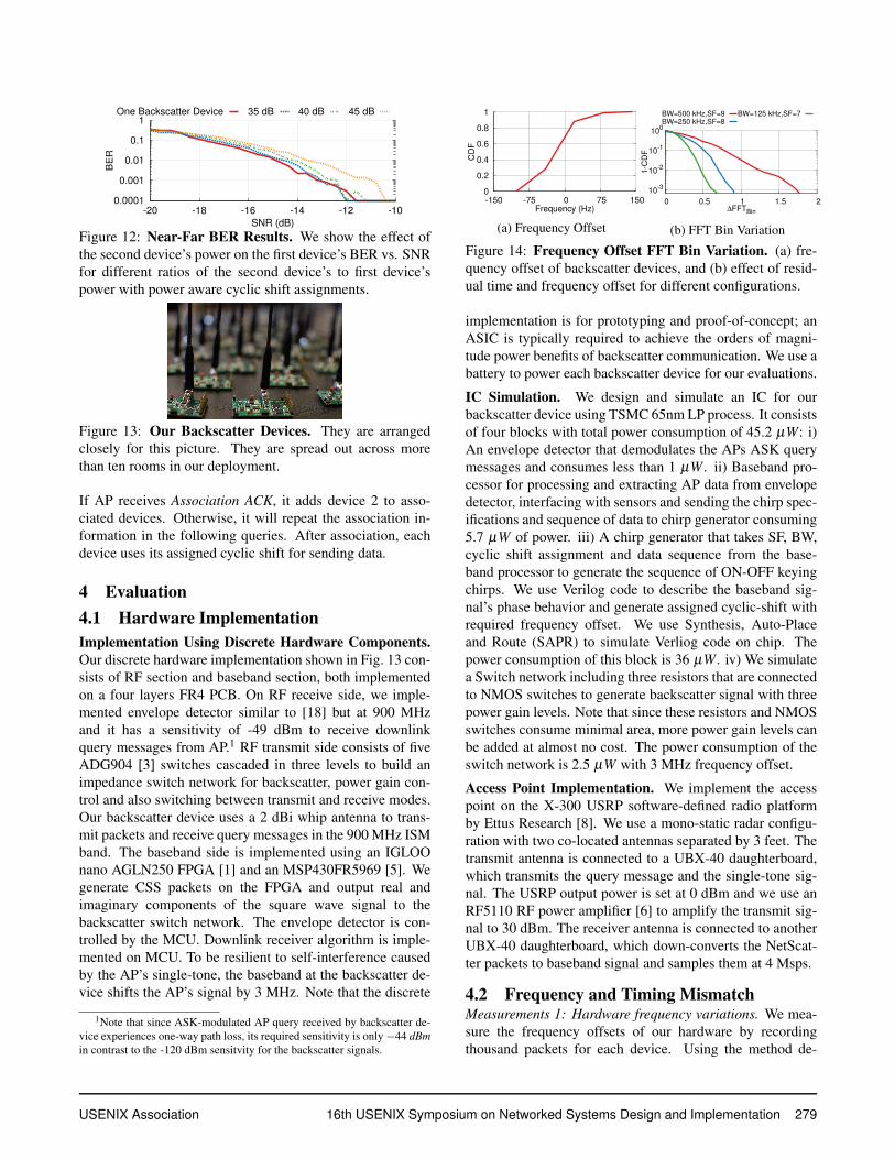
Figure 12: Near-Far BER Results. We show the effect ofthe second device’s power on the first device’s BER vs. SNRfor different ratios of the second device’s to first device’spower with power aware cyclic shift assignments.
Figure 13: Our Backscatter Devices. They are arrangedclosely for this picture. They are spread out across morethan ten rooms in our deployment.
If AP receives Association ACK, it adds device 2 to asso-ciated devices. Otherwise, it will repeat the association in-formation in the following queries. After association, eachdevice uses its assigned cyclic shift for sending data.
4 Evaluation4.1 Hardware ImplementationImplementation Using Discrete Hardware Components.Our discrete hardware implementation shown in Fig. 13 con-sists of RF section and baseband section, both implementedon a four layers FR4 PCB. On RF receive side, we imple-mented envelope detector similar to [18] but at 900 MHzand it has a sensitivity of -49 dBm to receive downlinkquery messages from AP.1 RF transmit side consists of fiveADG904 [3] switches cascaded in three levels to build animpedance switch network for backscatter, power gain con-trol and also switching between transmit and receive modes.Our backscatter device uses a 2 dBi whip antenna to trans-mit packets and receive query messages in the 900 MHz ISMband. The baseband side is implemented using an IGLOOnano AGLN250 FPGA [1] and an MSP430FR5969 [5]. Wegenerate CSS packets on the FPGA and output real andimaginary components of the square wave signal to thebackscatter switch network. The envelope detector is con-trolled by the MCU. Downlink receiver algorithm is imple-mented on MCU. To be resilient to self-interference causedby the AP’s single-tone, the baseband at the backscatter de-vice shifts the AP’s signal by 3 MHz. Note that the discrete
1Note that since ASK-modulated AP query received by backscatter de-vice experiences one-way path loss, its required sensitivity is only−44 dBmin contrast to the -120 dBm sensitvity for the backscatter signals.
0
0.2
0.4
0.6
0.8
1
-150 -75 0 75 150
CD
F
Frequency (Hz)
(a) Frequency Offset
10-3
10-2
10-1
100
0 0.5 1 1.5 2
1-C
DF
∆FFTBin
BW=500 kHz,SF=9
BW=250 kHz,SF=8
BW=125 kHz,SF=7
(b) FFT Bin Variation
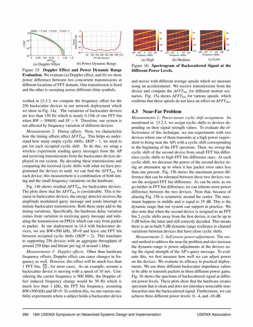
Figure 14: Frequency Offset FFT Bin Variation. (a) fre-quency offset of backscatter devices, and (b) effect of resid-ual time and frequency offset for different configurations.
implementation is for prototyping and proof-of-concept; anASIC is typically required to achieve the orders of magni-tude power benefits of backscatter communication. We use abattery to power each backscatter device for our evaluations.
IC Simulation. We design and simulate an IC for ourbackscatter device using TSMC 65nm LP process. It consistsof four blocks with total power consumption of 45.2 µW: i)An envelope detector that demodulates the APs ASK querymessages and consumes less than 1 µW. ii) Baseband pro-cessor for processing and extracting AP data from envelopedetector, interfacing with sensors and sending the chirp spec-ifications and sequence of data to chirp generator consuming5.7 µW of power. iii) A chirp generator that takes SF, BW,cyclic shift assignment and data sequence from the base-band processor to generate the sequence of ON-OFF keyingchirps. We use Verilog code to describe the baseband sig-nal’s phase behavior and generate assigned cyclic-shift withrequired frequency offset. We use Synthesis, Auto-Placeand Route (SAPR) to simulate Verliog code on chip. Thepower consumption of this block is 36 µW. iv) We simulatea Switch network including three resistors that are connectedto NMOS switches to generate backscatter signal with threepower gain levels. Note that since these resistors and NMOSswitches consume minimal area, more power gain levels canbe added at almost no cost. The power consumption of theswitch network is 2.5 µW with 3 MHz frequency offset.
Access Point Implementation. We implement the accesspoint on the X-300 USRP software-defined radio platformby Ettus Research [8]. We use a mono-static radar configu-ration with two co-located antennas separated by 3 feet. Thetransmit antenna is connected to a UBX-40 daughterboard,which transmits the query message and the single-tone sig-nal. The USRP output power is set at 0 dBm and we use anRF5110 RF power amplifier [6] to amplify the transmit sig-nal to 30 dBm. The receiver antenna is connected to anotherUBX-40 daughterboard, which down-converts the NetScat-ter packets to baseband signal and samples them at 4 Msps.
4.2 Frequency and Timing MismatchMeasurements 1: Hardware frequency variations. We mea-sure the frequency offsets of our hardware by recordingthousand packets for each device. Using the method de-
USENIX Association 16th USENIX Symposium on Networked Systems Design and Implementation 279
10-3
10-2
10-1
100
0 0.25 0.5 0.75 1 1.25 1.5
1-C
DF
∆FFTBin
5 m/s3 m/s1 m/sStatic
(a) Doppler Effect
-40
-30
-20
-10
0
64 128 192 256 320 384 448 512
Po
we
r
Diffe
ren
ce
(d
B)
FFT Bin Number
(b) Power Dynamic Range
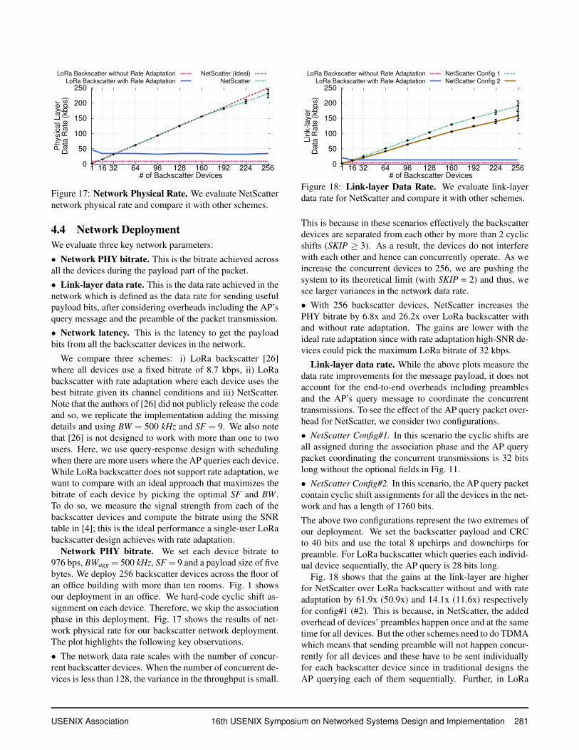
Figure 15: Doppler Effect and Power Dynamic RangeEvaluation. We evaluate (a) Doppler effect, and (b) we showpower difference between two concurrent transmissions atdifferent locations of FFT domain. One transmission is fixedand the other is sweeping across different chirp symbols.
scribed in §3.3.3, we compute the frequency offset for the256 backscatter devices in our network deployment whichwe show in Fig. 14a. The variations of backscatter devicesare less than 150 Hz which is nearly 0.15th of one FFT binwhen BW = 500kHz and SF = 9. Therefore, our system isnot affected by frequency variation of different devices.
Measurements 2: Timing offsets. Next, we characterizehow the timing offsets affect ∆FFTbin. This helps us under-stand how many empty cyclic shifts, SKIP− 1, we need toput for each occupied cyclic shift. To do this, we setup awireless experiment sending query messages from the APand receiving transmissions from the backscatter devices de-ployed in our system. By decoding these transmissions andcomparing the received cyclic shifts with what we have pro-grammed the devices to send, we can find the ∆FFTbin foreach device; this measurement is a combination of both tim-ing and the small frequency variations on the hardware.
Fig. 14b shows residual ∆FFTbin for backscatter devices.The plots show that the ∆FFTbin is considerable. This is be-cause in backscatter devices, the energy detector receives theamplitude modulated query message and sends interrupt toinitiate backscatter transmission. Both these steps add to thetiming variations. Specifically, the hardware delay variationcomes from variation in receiving query message and initi-ating the transmission on FPGA which can vary from packetto packet. In our deployment in §4.4 with backscatter de-vices, we use BW=500 kHz, SF=9 and leave one FFT binbetween occupied cyclic shifts (SKIP = 2). This translatesto supporting 256 devices with an aggregate throughput ofaround 250 kbps and bitrate per tag of around 1 kbps.
Measurements 3: Doppler effects. Other than hardwarefrequency offsets, Doppler effect can cause changes in fre-quency as well. However, this effect will be much less than1 FFT bin, BW
2SF , for most cases. As an example, assume abackscatter device is moving with a speed of 10 m/s. Con-sidering the carrier frequency is 900 MHz, the Doppler ef-fect induced frequency change would be 30 Hz which ismuch less than 1 kHz, the FFT bin frequency, assumingBW=500 kHz and SF=9. To confirm this, we run various mo-bility experiments where a subject holds a backscatter device
-250 -125 0 125 250
Frequency (KHz)
-120
-100
-80
-60
(a) High
-250 -125 0 125 250
Frequency (KHz)
-120
-100
-80
-60
(b) Medium
-250 -125 0 125 250
Frequency (KHz)
-120
-100
-80
-60
(c) Low
Figure 16: Spectrogram of Backscattered Signal at theDifferent Power Levels.
and moves with different average speeds which we measureusing an accelerometer. We receive transmissions from thedevice and compute the ∆FFTbin for different motion sce-narios. Fig. 15a shows ∆FFTbin for various speeds, whichconfirms that these speeds do not have an effect on ∆FFTbin.
4.3 Near-Far ProblemMeasurements 1: Power-aware cyclic shift assignment. Asmentioned in §3.2.3, we assign cyclic shifts to devices de-pending on their signal strength values. To evaluate the ef-fectiveness of this technique, we run experiments with twodevices where one of them transmits at a high power (equiv-alent to being near the AP) with a cyclic shift correspondingto the beginning of the FFT spectrum. Then, we sweep thecyclic shift of the second device from small FFT bin differ-ence cyclic shifts to high FFT bin difference ones. At eachcyclic shift, we decrease the power of the second device us-ing an attenuator up to when it has packet error rates lessthan one percent. Fig. 15b shows the maximum power dif-ference that can be tolerated between these two devices ver-sus the assigned FFT bin difference. As can be seen, as wego further in FFT bin difference, we can tolerate more powerdifference between the two devices. Note that, because ofaliasing Fig. 15b is symmetric around the center. The max-imum happens in middle and is equal to 35 dB. This is thedynamic range that our system can support in practice. Wealso note that when the second device is assigned to an FFTbin 2 cyclic shifts away from the first device, it can be up to5 dB below the latter and still correctly decoded. This meansthere is an in-built 5 dB dynamic range resilience to channelvariations between devices that have close cyclic shifts.
Measurements 2: Self-aware power-adjustment. The sec-ond method to address the near-far problem and also increasethe dynamic-range is power adjustments at the devices us-ing the signal strength of the AP’s query message. To eval-uate this, we first measure how well we can adjust poweron the devices. We evaluate its efficacy in practical deploy-ments. We use three different backscatter impedance valuesto be able to transmit packets in three different power gains.Fig. 16 shows the spectrum of backscattered signal at differ-ent power levels. These plots show that the hardware createsspectrum that is clean and does not introduce noticeable non-linearities into the backscattered signal. Furthermore, we canachieve three different power levels: 0, -4, and -10 dB.
280 16th USENIX Symposium on Networked Systems Design and Implementation USENIX Association
0
50
100
150
200
250
1 16 32 64 96 128 160 192 224 256
Ph
ysic
al L
aye
rD
ata
Ra
te (
kb
ps)
# of Backscatter Devices
LoRa Backscatter without Rate Adaptation
LoRa Backscatter with Rate Adaptation
NetScatter (Ideal)
NetScatter
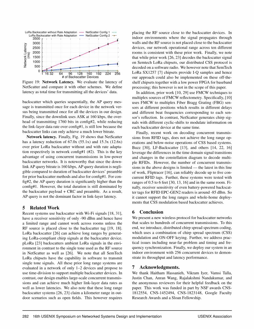
Figure 17: Network Physical Rate. We evaluate NetScatternetwork physical rate and compare it with other schemes.
4.4 Network DeploymentWe evaluate three key network parameters:
• Network PHY bitrate. This is the bitrate achieved acrossall the devices during the payload part of the packet.• Link-layer data rate. This is the data rate achieved in thenetwork which is defined as the data rate for sending usefulpayload bits, after considering overheads including the AP’squery message and the preamble of the packet transmission.• Network latency. This is the latency to get the payloadbits from all the backscatter devices in the network.
We compare three schemes: i) LoRa backscatter [26]where all devices use a fixed bitrate of 8.7 kbps, ii) LoRabackscatter with rate adaptation where each device uses thebest bitrate given its channel conditions and iii) NetScatter.Note that the authors of [26] did not publicly release the codeand so, we replicate the implementation adding the missingdetails and using BW = 500 kHz and SF = 9. We also notethat [26] is not designed to work with more than one to twousers. Here, we use query-response design with schedulingwhen there are more users where the AP queries each device.While LoRa backscatter does not support rate adaptation, wewant to compare with an ideal approach that maximizes thebitrate of each device by picking the optimal SF and BW.To do so, we measure the signal strength from each of thebackscatter devices and compute the bitrate using the SNRtable in [4]; this is the ideal performance a single-user LoRabackscatter design achieves with rate adaptation.
Network PHY bitrate. We set each device bitrate to976 bps, BWagg = 500 kHz, SF = 9 and a payload size of fivebytes. We deploy 256 backscatter devices across the floor ofan office building with more than ten rooms. Fig. 1 showsour deployment in an office. We hard-code cyclic shift as-signment on each device. Therefore, we skip the associationphase in this deployment. Fig. 17 shows the results of net-work physical rate for our backscatter network deployment.The plot highlights the following key observations.
• The network data rate scales with the number of concur-rent backscatter devices. When the number of concurrent de-vices is less than 128, the variance in the throughput is small.
0
50
100
150
200
250
1 16 32 64 96 128 160 192 224 256
Lin
k-la
ye
rD
ata
Ra
te (
kb
ps)
# of Backscatter Devices
LoRa Backscatter without Rate Adaptation
LoRa Backscatter with Rate Adaptation
NetScatter Config 1
NetScatter Config 2
Figure 18: Link-layer Data Rate. We evaluate link-layerdata rate for NetScatter and compare it with other schemes.
This is because in these scenarios effectively the backscatterdevices are separated from each other by more than 2 cyclicshifts (SKIP ≥ 3). As a result, the devices do not interferewith each other and hence can concurrently operate. As weincrease the concurrent devices to 256, we are pushing thesystem to its theoretical limit (with SKIP = 2) and thus, wesee larger variances in the network data rate.• With 256 backscatter devices, NetScatter increases thePHY bitrate by 6.8x and 26.2x over LoRa backscatter withand without rate adaptation. The gains are lower with theideal rate adaptation since with rate adaptation high-SNR de-vices could pick the maximum LoRa bitrate of 32 kbps.
Link-layer data rate. While the above plots measure thedata rate improvements for the message payload, it does notaccount for the end-to-end overheads including preamblesand the AP’s query message to coordinate the concurrenttransmissions. To see the effect of the AP query packet over-head for NetScatter, we consider two configurations.• NetScatter Config#1. In this scenario the cyclic shifts areall assigned during the association phase and the AP querypacket coordinating the concurrent transmissions is 32 bitslong without the optional fields in Fig. 11.• NetScatter Config#2. In this scenario, the AP query packetcontain cyclic shift assignments for all the devices in the net-work and has a length of 1760 bits.The above two configurations represent the two extremes ofour deployment. We set the backscatter payload and CRCto 40 bits and use the total 8 upchirps and downchirps forpreamble. For LoRa backscatter which queries each individ-ual device sequentially, the AP query is 28 bits long.
Fig. 18 shows that the gains at the link-layer are higherfor NetScatter over LoRa backscatter without and with rateadaptation by 61.9x (50.9x) and 14.1x (11.6x) respectivelyfor config#1 (#2). This is because, in NetScatter, the addedoverhead of devices’ preambles happen once and at the sametime for all devices. But the other schemes need to do TDMAwhich means that sending preamble will not happen concur-rently for all devices and these have to be sent individuallyfor each backscatter device since in traditional designs theAP querying each of them sequentially. Further, in LoRa
USENIX Association 16th USENIX Symposium on Networked Systems Design and Implementation 281
0
500
1000
1500
2000
2500
3000
3500
1 16 32 64 96 128 160 192 224 256
Ne
two
rk L
ate
ncy
(ms)
# of Backscatter Devices
LoRa Backscatter without Rate Adaptation
LoRa Backscatter with Rate Adaptation
NetScatter Config 1
NetScatter Config 2
Figure 19: Network Latency. We evaluate the latency ofNetScatter and compare it with other schemes. We definelatency as total time for transmitting all the devices’ data.
backscatter which queries sequentially, the AP query mes-sage is transmitted once for each device in the network ver-sus being transmitted once for all the devices in our design.Finally, since the downlink uses ASK at 160 kbps, the over-head of transmitting 1760 bits in config#2, while reducingthe link-layer data rate over config#1, is still low because thebackscatter links can only achieve a much lower bitrate.
Network latency. Finally, Fig. 19 shows that NetScatterhas a latency reduction of 67.0x (55.1x) and 15.3x (12.6x)over prior LoRa backscatter without and with rate adapta-tion respectively in network config#1 (#2). This is the keyadvantage of using concurrent transmissions in low-powerbackscatter networks. It is noteworthy that since the down-link AP query bitrate is 160 kbps, AP query duration is negli-gible compared to duration of backscatter devices’ preamblefor prior backscatter methods and also for config#1. For con-fig#2, the AP query duration is significantly higher than theconfig#1. However, the total duration is still dominated bythe backscatter payload + CRC and preamble. As a result,AP query is not the dominant factor in link-layer latency.
5 Related WorkRecent systems use backscatter with Wi-Fi signals [18, 31],have a receiver sensitivity of only -90 dBm and hence havea limited range and cannot work across rooms unless theRF source is placed close to the backscatter tag [19, 18].LoRa backscatter [26] can achieve long ranges by generat-ing LoRa-compliant chirp signals at the backscatter device.pLoRa [23] backscatters ambient LoRa signals in the envi-ronment in contrast to the single tone used as the RF sourcein NetScatter as well as [26]. We note that all SemTechLoRa chipsets have the capability in software to transmitsingle tone signals. All these prior long range systems areevaluated in a network of only 1–2 devices and propose touse time-division to support multiple backscatter devices. Incontrast, our design enables large-scale concurrent transmis-sions and can achieve much higher link-layer data rates aswell as lower latencies. We also note that these long rangebackscatter systems [26, 23] claim a kilometer range in out-door scenarios such as open fields. This however requires
placing the RF source close to the backscatter devices. Inindoor environments where the signal propagates throughwalls and the RF source is not placed close to the backscatterdevices, our network operational range across ten differentrooms is consistent with these prior work. Finally, we notethat while prior work [26, 23] decodes the backscatter signalon Semtech LoRa chipsets, our distributed CSS protocol isdecoded on a software radio. We however note that SemTechLoRa SX1257 [7] chipsets provide I-Q samples and henceour approach could also be implemented on these off-the-shelf chipsets together with a low power FPGA for basebandprocessing; this however is not in the scope of this paper.
In addition, prior work [10, 29] use FMCW techniques tomultiplex sources of FMCW reflectometry. Specifically, [10]uses FMCW to multiplex Fiber Bragg Grating (FBG) sen-sors at different positions which results in different delaysand different beat frequencies corresponding to each sen-sor’s reflection. In contrast, NetScatter generates chirp sig-nals with different cyclic-shifts to modulate information oneach backscatter device at the same time.
Finally, recent work on decoding concurrent transmis-sions from RFID tags, does not achieve the long range op-erations and below-noise operations of CSS based systems.Buzz [30], LF-Backscatter [13], and others [14, 22, 16]leverage the differences in the time domain signal transitionsand changes in the constellation diagram to decode multi-ple RFIDs. However, the number of concurrent transmis-sions in the above designs is limited — the latest in this lineof work, Fliptracer [16], can reliably decode up to five con-current RFID tags. Further, these systems were tested withranges of 0.5 to 6 feet [30, 13, 16] and in the same room. Fi-nally, receiver sensitivity of even battery-powered backscat-ter tags for RFID EPC-GEN2 readers is around -85 dBm. Soit cannot support the long ranges and whole-home deploy-ments that CSS modulation based backscatter achieves.
6 ConclusionWe present a new wireless protocol for backscatter networksthat scales to hundreds of concurrent transmissions. To thisend, we introduce, distributed chirp spread spectrum coding,which uses a combination of chirp spread spectrum (CSS)modulation and ON-OFF keying. Further, we address prac-tical issues including near-far problem and timing and fre-quency synchronization. Finally, we deploy our system in anindoor environment with 256 concurrent devices to demon-strate its throughput and latency performance.
7 Acknowledgments.We thank Haitham Hassanieh, Vikram Iyer, Vamsi Talla,Justin Chan, Anran Wang, Rajalakshmi Nandakumar, andthe anonymous reviewers for their helpful feedback on thepaper. This work was funded in part by NSF awards CNS-1812554, CNS-1452494, CNS-1823148, Google FacultyResearch Awards and a Sloan Fellowship.
282 16th USENIX Symposium on Networked Systems Design and Implementation USENIX Association
References[1] Igloo nano fpga datasheet by, 2015. https://
www.microsemi.com/document-portal/doc download/130695-igloo-nano-low-power-flash-fpgas-datasheet.
[2] Xrcha-f-a series, 2015. https://www.murata.com/˜/media/webrenewal/products/timingdevice/crystalu/flyers/vppt-hcrj078-d.ashx?la=en-us.
[3] Adg904 datasheet by analog devices, 2016. http://www.analog.com/media/en/technical-documentation/data-sheets/ADG904.pdf.
[4] Sx1276 datasheet by semtech, 2016. https://www.semtech.com/uploads/documents/sx1276.pdf.
[5] Msp430fr5969 datasheet by ti, 2017. http://www.ti.com/lit/ds/symlink/msp430fr5969.pdf.
[6] Rf5110 rf power amplifier, 2018. http://www.rfmd.com/store/downloads/dl/file/id/30508/5110g product data sheet.pdf.
[7] Sx1257 datasheet by semtech, 2018. https://www.semtech.com/uploads/documents/DS SX1257 V1.2.pdf.
[8] Usrp x-300, 2018. https://www.ettus.com/product/details/X300-KIT.
[9] A. Berni and W. Gregg. On the utility of chirp modulation for digitalsignaling. IEEE Transactions on Communications, 1973.
[10] P. K. Chan, W. Jin, J. Gong, and N. Demokan. Multiplexing offiber bragg grating sensors using a fmcw technique. IEEE PhotonicsTechnology Letters, 11(11):1470–1472, 1999.
[11] D. M. Devasirvatham. Time delay spread measurements of widebandradio signals within a building. Electronics Letters, 20(23):950–951,1984.
[12] R. Eletreby, D. Zhang, S. Kumar, and O. Yagan. Empowering low-power wide area networks in urban settings. SIGCOMM ’17.
[13] P. Hu, P. Zhang, and D. Ganesan. Laissez-faire: Fully asymmet-ric backscatter communication. In Proceedings of the 2015 ACMConference on Special Interest Group on Data Communication, SIG-COMM ’15.
[14] P. Hu, P. Zhang, and D. Ganesan. Leveraging interleaved signal edgesfor concurrent backscatter. In hotWireless, 2014.
[15] V. Iyer, V. Talla, B. Kellogg, S. Gollakota, and J. Smith. Inter-technology backscatter: Towards internet connectivity for implanteddevices. In Proceedings of the 2016 ACM SIGCOMM Conference.
[16] M. Jin, Y. He, X. Meng, Y. Zheng, D. Fang, and X. Chen. Flip-tracer: Practical parallel decoding for backscatter communication. InProceedings of the 23rd Annual International Conference on MobileComputing and Networking, MobiCom ’17.
[17] B. Kellogg, A. Parks, S. Gollakota, J. R. Smith, and D. Wetherall.Wi-fi backscatter: Internet connectivity for rf-powered devices. InProceedings of the 2014 ACM Conference on SIGCOMM.
[18] B. Kellogg, V. Talla, S. Gollakota, and J. R. Smith. Passive wi-fi:Bringing low power to wi-fi transmissions. In NSDI 16.
[19] M. Kotaru, P. Zhang, and S. Katti. Localizing low-power backscattertags using commodity wifi. In CoNext’17.
[20] V. Liu, A. Parks, V. Talla, S. Gollakota, D. Wetherall, and J. R. Smith.Ambient backscatter: Wireless communication out of thin air. SIG-COMM ’13.
[21] S. Naderiparizi, M. Hessar, V. Talla, S. Gollakota, and J. R. Smith. To-wards battery-free hd video streaming. In 15th USENIX Symposiumon Networked Systems Design and Implementation (NSDI 18), 2018.
[22] J. Ou, M. Li, and Y. Zheng. Come and be served: Parallel decodingfor cots rfid tags. In Proceedings of the 21st Annual InternationalConference on Mobile Computing and Networking, pages 500–511.ACM, 2015.
[23] Y. Peng, L. Shangguan, Y. Hu, Y. Qian, X. Lin, X. Chen, D. Fang, andK. Jamieson. Plora: a passive long-range data network from ambi-ent lora transmissions. In Proceedings of the 2018 Conference of theACM Special Interest Group on Data Communication, SIGCOMM’18, pages 147–160. ACM, 2018.
[24] A. A. Saleh and R. Valenzuela. A statistical model for indoor multi-path propagation. IEEE Journal on selected areas in communications,5(2):128–137, 1987.
[25] N. Sornin and L. Champion. Signal concentrator device, Oct. 17 2017.US Patent 9,794,095.
[26] V. Talla, M. Hessar, B. Kellogg, A. Najafi, J. R. Smith, and S. Gol-lakota. Lora backscatter: Enabling the vision of ubiquitous connectiv-ity. Proc. ACM Interact. Mob. Wearable Ubiquitous Technol., 2017.
[27] D. Tse and P. Viswanath. Fundamentals of wireless communication.Cambridge university press, 2005.
[28] A. Varshney, O. Harms, C. M. Perez-Penichet, C. Rohner, F. Hermans,and T. Voigt. Lorea: A backscaer architecture that achieves a longcommunication range. Sensys’17.
[29] A. Vasilyev. The optoelectronic swept-frequency laser and itsapplications in ranging, three-dimensional imaging, and coherentbeam combining of chirped-seed amplifiers. PhD thesis, CaliforniaInstitute of Technology, 2013.
[30] J. Wang, H. Hassanieh, D. Katabi, and P. Indyk. Efficient and reliablelow-power backscatter networks. In SIGCOMM 2012.
[31] P. ZHANG, M. Rostami, P. Hu, and D. Ganesan. Enabling practicalbackscatter communication for on-body sensors. In Proceedings ofthe 2016 ACM SIGCOMM Conference.
USENIX Association 16th USENIX Symposium on Networked Systems Design and Implementation 283