nepal electricity authority - nea.org.np · 1.1 nepal electricity authority is implementing the...
TRANSCRIPT

Nepal Electricity Authority (A Government of Nepal Undertaking)
Transmission Directorate
NEPAL-INDIA ELECTRICITY TRANSMISSION AND TRADE PROJECT
ICB No: NIETTP/G/ICB-2/TRANS
Bidding Document for
Procurement of Plant Design, Supply and Installation of Power Transformer and Reactor
(Single Stage Bidding)
Volume II of III
March, 2014

2-1
Table of Contents Invitation for Bids Volume I – Bidding Procedures .......................................................................................... 1-1
Section I. Instructions to Bidders .................................................................................... 1-3 Section II. Bid Data Sheet ............................................................................................. 1-33 Section III. Evaluation and Qualification Criteria ....................................................... 1- 39 Section IV. Bidding Forms ........................................................................................... 1-51 Section V. Eligible Countries ....................................................................................... 1-84
Volume II –Employer’s Requirements ............................................................................. 2-1
Section VI. Employer’s Requirements ........................................................................ 2-1
Volume III – Conditions of Contract and Contract Forms ............................................ 3-1 Section VII. General Conditions (GC)............................................................................. 3-3 Section VIII. Particular Conditions ............................................................................... 3-84 Section IX. - Contract Forms ........................................................................................ 3-93

2-2
PART 2 –Employer’s Requirements
Section VI. Employer’s Requirements

Nepal Electricity Authority (A Government of Nepal Undertaking)
Transmission Directorate
NEPAL-INDIA ELECTRICITY TRANSMISSION AND TRADE PROJECT
ICB No: NIETTP/G/ICB-2/TRANS
Bidding Document for
Procurement of Plant Design, Supply and Installation of Power Transformer and Reactor
(Single Stage Bidding)
Volume II of III
March, 2014

Volume-II
Technical Specification, Chapter 1- Project Specification Requirement (PSR) 1- 2
CHAPTER 1 PROJECT SPECIFICATION REQUIREMENT

Volume-II
Technical Specification, Chapter 1- Project Specification Requirement (PSR) 1- 3
Chapter 1- PROJECT SPECIFICATION REQUIREMENT (PSR)
INDEX
Cl. No. DESCRIPTION PAGE NO.
1 GENERAL 3
2 SCOPE 4
3 SPECIFIC EXCLUSIONS 5
4 PHYSICAL AND OTHER PARAMETERS 6
5 SCHEDULE OF QUANTITIES 7
6 ORDER OF PRECEDENCE OF DIFFERENT CHAPTERS OF TECHNICAL SPECIFICATION
7
7 APPROVAL OF DRAWINGS/DESIGN DOCUMENTS
8
8 TRAINING TO EMPLOYER'S PERSONNEL 8

Volume-II
Technical Specification, Chapter 1- Project Specification Requirement (PSR) 1- 4
Chapter 1- Project Specification Requirement (PSR) 1.0 GENERAL
1.1 Nepal Electricity Authority is implementing the 400kV Hetauda-Dhalkebar-
Duhabi Transmission Line Project as a part of the Nepal India Electricity Transmission and Trade Project (NIETTP) which includes the following components:
a) 400kV Hetauda-Dhalkebar-Inaruwa Transmission Line (to be initially charged at 220kV voltage level)
b) New 220/132/33 kV Substation at Inaruwa c) 220kV (New) Substation and extension of 132kV substation at
Dhalkebar & Hetauda . As part of the above project 285 Km long 400 kV D/C Transmission Line initially to be charged at 220 kV is currently under construction, 2X160 MVA, 220/132 kV Autotransformers at Dhalkebar and 2x100MVA, 220/132kV Autotransformers each at Hetauda & Inaruwa Substations are to be installed. One number of 132/11 kV, 10 MVA power transformers is also to be installed at Hetaunda. Further 2x63MVA, 220/33kV Transformers and 1x132kV Reactor is to be installed at Inaruwa substation. The bid opening of the substation package took place on February 2, 2014 and the received bids ae currently being evaluated. Power Grid Corporation of India Limited (PGCIL) has been appointed as an Owners Engineer to assist Employer for the execution of works under the Contract. The responsibilities of Owner’s Engineer include review of detail design, drawings and other technical documents submitted by the Contractor, supervision during construction, quality assurance, assistance in Factory acceptance testing of major materials, supervision of testing and commissioning of the substations and various contract/project management activities.
1.2 Associated Transmission System:
The following transmission system is envisaged under the project:- Transmission lines 1. Dhalkebar – Hetauda 400 kV D/C Lines: 131 km (along with
OPGW)
2. Dhalkebar- Inaruwa 400 kV D/C Lines: 154 km (along with OPGW)

Volume-II
Technical Specification, Chapter 1- Project Specification Requirement (PSR) 1- 5
3. Muzaffarpur –- Dhalkebar 400kV D/C: 140 km (along with OPGW)
(Part of line i.e. 100 km in INDIA to be constructed by CPTC and balance 40 km) to be constructed by PTCN) Besides, following transmission lines are being constructed by NEA under other system strengthening/generation linked schemes:-
1. LILO of 132kV Duhabi- Lahan D/C Lines at Inaruwa Substation
2. Inaruwa- Koshi Corridor 220 kV D/C lines …110 km
3. Bharatpur – Hetauda 220kV D/C Lines …72 km
Substations 1. Construction of 220/132/33kV (New) Substation at Inaruwa.
2. Construction of 220kV (New) Substation and extension of 132kV at Dhalkebar & Hetauda substations.
2.0 SCOPE
TRANSFORMER & REACTOR PACKAGE:
The scope of this package covers the following power transformers & Bus Reactor along with tools & testing equipment, all fittings, accessories and marshalling box etc. for each power transformer as per technical specifications.
i) 2 nos. 220/132 kV, 160 MVA, 3-Phase Power Transformer for Dhalkebar substation.
ii) 2 nos. 220/132 kV, 100 MVA, 3-Phase Power Transformer for Hetauda substation
iii) 1 nos. 132/11 kV, 10 MVA, 3-Phase Power Transformer for Hetauda substation
iv) 2 nos. 220/132 kV, 100 MVA, 3-Phase Power Transformer and 2 nos. 220/33 kV, 63 MVA, 3-Phase Transformer for Inaruwa substation.
v) 1 no. 145 kV, 25MVAR, 3-Phase Bus Reactor at Inaruwa substation.

Volume-II
Technical Specification, Chapter 1- Project Specification Requirement (PSR) 1- 6
The detailed scope of works is brought out in the subsequent clauses of this Chapter.
2.1 Design, engineering, manufacture, testing at manufacturer’s works, transportation, unloading and delivery at site including insurance & storage, erection, testing and commissioning at Site, complete in all respect for the above mentioned power transformers & Bus Reactor.
2.2 The Contractor shall also be responsible for the overall co-ordination
with internal/external agencies, other contractors and project management.
2.3 The scope includes training of Employer's manpower and testing &
commissioning as specified in the Schedules of Rates and Prices. 2.4 The scope includes supply of transformer bushing end terminal
connectors suitable for 220kV single Moose ACSR Conductor, 132kV Twin Moose ACSR Conductor, 33kV Twin AAC Bull Conductor and bus reactor bushing end terminal connectors suitable for 145kV single Moose ACSR Conductor and Supply of Testing & maintenance equipment as specified in Schedules of Rates and Prices.
2.5 Design of transformers/Reactor and its associated electrical and
mechanical auxiliaries systems includes designs and drawings and relevant documents as required for detailed engineering are covered under the scope of the Contractor.
2.6 The Contractor shall be responsible to select and verify the route, mode
of transportation and make all necessary arrangement with the appropriate authorities for the transportation of the equipment. The dimension of the equipment shall be such that when packed for transportation, it will comply with the requirements of loading and clearance restrictions for the selected route. It shall be the responsibility of the contractor to coordinate the arrangement for transportation of the Transformers for all the stages from the manufacturer’s work to site.
The conditions of roads, capacity of bridges, culverts etc. in the route
shall also be assessed by the bidders. The scope of any necessary modification/ extension/ improvement to existing road, bridges, culverts etc. shall be included in the scope of the bidder. The contractor shall carry out the route survey along with the transporter and submit the detail proposal and methodology for transportation of transformers and reactor for approval of Employer within three months from the date of award

Volume-II
Technical Specification, Chapter 1- Project Specification Requirement (PSR) 1- 7
2.7 In Chapter 2 GTR-Transformer & Reactor and other Technical specifications, the term “Purchaser” and/or “Owner” may be read as “Employer”.
3.0 SPECIFIC EXCLUSIONS FROM THE SCOPE
The following items are specifically excluded from the scope of this specification:
a) Overhead connection from HV & LV bushings of the Transformers and Bus Reactor to substation equipment.
b) Supply, laying and termination of cables along with necessary accessories from common marshalling box of transformer to RTCC panels which is to be located in switchyard panel room at Dhalkebar & Inaruwa Substation & in Auxiliary Building at Hetauda Substation.
c) Supply, laying and termination of cables along with necessary
accessories from common marshalling box of transformer/Bus reactor to BCU & protection panels and ACDB/DCDB.
d) Earthing connection of Transformers and Bus Reactor to Employer's earthmat and earth electrode.
e) Foundations of Transformers along with jacking pad and pylon supports, rail track and fire resistant wall between Transformers. However contractor shall provide all required details for finalization of foundations.
f) Foundations of Bus Reactor along with jacking pad and pylon supports, rail track and fire resistant wall between Reactor and capacitor bank. However contractor shall provide all required details for finalization of foundations.
g) Fire protection system i.e. Hydrant System and High Velocity Water Spray System for Transformers and Bus Reactor.
h) Cable trenches along with covers, road/rail crossings, sump pits etc.
4.0 PHYSICAL AND OTHER PARAMETERS
4.1 Location of the Substation – All three substations (Inaruwa, Dhalkebar & Hetauda) of Nepal Electricity Authority are located near East – West Highway Road. For the purpose of transportation of goods, border entry points (with India) are Jogbani for Inaruwa S/S, and Raxaul for Hetauda & Dhalkebar.

Volume-II
Technical Specification, Chapter 1- Project Specification Requirement (PSR) 1- 8
4.2 Meteorological data :-
a) Altitude above sea level :
i) Hetauda – 474m, ii) Dhalkebar – 137m iii) Inaruwa – 81m
b) Ambient Air Temperature :
i) Hetauda – 36.5ºC (max)/7.2ºC (min) ii) Janakpur– 37.4ºC (max)/ 7.7ºC (min) Near Dhalkebar iii) Bratnagar-35.6ºC (max)/ 8.2ºC (min) Near Ineruwa
c) Average Humidity (in %) :
i) Hetauda – 94.62(max),53.5(min) ii) Janakpur (near Dhalkebar) – 86.28max), 33.06(min) iii) Biratnagar(near Inaruwa) – 96.72(max), 43.58(min)
d) The substation locations are lying in the wind speed Zone 47 m/s.
However, for design purposes, ambient temperature should be considered as 50 degree centigrade and altitude less than 1000m.
5.0 SCHEDULE OF QUANTITIES
The requirement of various items/equipment is indicated in the Schedules of Rates and Prices.
The bill of quantity of major equipment/items/works which are payable on unit rate is indicated in the Schedules of Rates and Prices. Wherever the quantities of items/works are not indicated, the bidder is required to estimate the quantity and incorporate their price in respective Schedules of Rates and Prices.
Bidder should include all such items in the Schedules of Rates and Prices which are not specifically mentioned but are essential for the execution of the contract. Item which explicitly may not appear in various schedules and required for successful commissioning shall be included in the bid price and shall be provided at no extra cost to Employer.
6.0 ORDER OF PREFERENCES OF DIFFERENT CHAPTERS OF
TECHNICAL SPECIFICATION

Volume-II
Technical Specification, Chapter 1- Project Specification Requirement (PSR) 1- 9
For the purpose of present scope of work, technical specification shall consist of following parts and they should be read in conjunction with each other.
Chapter 1 --- Project Specification Requirement (PSR) Chapter 2 --- General Technical Requirement (GTR) Chapter 3 --- 220kV Class Specifications for Transformers Chapter 4 --- 145kV Class Specifications for Reactor
In case of any discrepancy between Chapter 1- PSR, Chapter 2-GTR and other technical specifications on scope of works, Chapter 1- PSR shall prevail over all other Chapters.
In case of any discrepancy between Chapter 2-GTR and individual Chapters for various equipments, requirement of individual equipment Chapter shall prevail.
7.0 APPROVAL OF DRAWINGS/DESIGN DOCUMENTS
Employer shall be responsible for final approval of all drawings and documents. In order to facilitate approval process, contractor shall submit all drawings and documents to Consultant (in 2 sets) & Employer (in 3 sets). Employer shall forward consolidated comments/approval to the contractor.
8.0 TRAINING TO EMPLOYER'S PERSONNEL (at Manufacturer’s Works)
Contractor shall provide necessary training to Employer’s personnel in the field of design, engineering, operation & maintenance of equipments as per Schedules of Rates and Prices. The Contractor shall include in the training charges Employer trainees' lodging, local transportation, training materials, to and fro economy class air ticket from Nepal to place of training and payment of USD 100 per Diem allowances per trainee per day for the duration of training.

Volume-II
Technical Specification, Chapter 2 General Technical Requirement (GTR) 2-1
CHAPTER 2-GENERAL TECHNICAL REQUIREMENT (GTR)
Table of Content
Cl. No. DESCRIPTION PAGE NO. 1 FOREWORD 2
2 GENERAL REQUIREMENT 2
3 STANDARDS 2
4 SERVICES TO BE PERFORMED BY THE EQUIPMENT BEING FURNISHED
3
5 ENGINEERING DATA AND DRAWINGS 5
6 MATERIAL/ WORKMANSHIP 7
7 DESIGN IMPROVEMENTS / COORDINATION 10
8 QUALITY ASSURANCE PROGRAMME 10
9 TYPE TESTING, INSPECTION, TESTING & INSPECTION CERTIFICATE
11
10 TESTS 13
11 PACKAGING & PROTECTION 13 12 FINISHING OF METAL SURFACES 14
13 HANDLING, STORING AND INSTALLATION 14
14 SPECIAL TOOLS AND TACKLES 15
15 AUXILIARY SUPPLY 15
16 CONTROL CABINETS, JUNCTION BOXES, TERMINAL BOXES & MARSHALLING BOXES FOR OUTDOOR EQUIPMENT
16
17 SUPPORT STRUCTURE 17
18 TERMINAL BLOCKS AND WIRING 17
19 LAMPS AND SOCKETS 18
20 BUSHINGS, HOLLOW COLUMN INSULATORS, SUPPORT INSULATORS
19
ANNEXURE - A 20
ANNEXURE - B 21
Volume-II
Technical Specification, Chapter 2 General Technical Requirement (GTR) 2-2
1.0 FOREWORD
1.1 The provisions under this Chapter are intended to supplement general requirements for the materials, equipments and services covered under other Chapters of tender documents and is not exclusive. However in case of conflict between the requirements specified in this Chapter and requirements specified under other Chapters, the requirements specified under respective Chapters shall prevail.
2.0 GENERAL REQUIREMENT
2.1 The bidders shall submit the technical requirements, data and information as per the technical data sheets provided in the bid documents.
2.2 The bidders shall furnish catalogues, engineering data, technical information, design documents, drawings etc., fully in conformity with the technical specification. An indicative list of such drawings and documents for transformer and reactor are enclosed in Annexure-A.
2.3 It is recognised that the Contractor may have standardised on the use of certain components, materials, processes or procedures different from those specified herein. Alternate proposals offering similar equipment based on the manufacturer’s standard practice will also be considered provided such proposals meet the specified designs, standard and performance requirements and are acceptable to the Employer. Unless brought out clearly, the Bidder shall be deemed to conform to this specification scrupulously. All deviations from the specification shall be clearly brought out in the respective schedule of deviations. Any discrepancy between the specification and the catalogues or the bid, if not clearly brought out in the specific requisite schedule, will not be considered as valid deviation.
2.4 Wherever a material or article is specified or defined by the name of a particular brand, Manufacturer or Vendor, the specific name mentioned shall be understood as establishing type, function and quality and not as limiting competition.
2.5 Equipment furnished shall be complete in every respect with all mountings, fittings, fixtures and standard accessories normally provided with such equipment and/or needed for erection, completion and safe operation of the equipment as required by applicable codes though they may not have been specifically detailed in the Technical Specifications unless included in the list of exclusions. Materials and components not specifically stated in the specification but which are necessary for commissioning and satisfactory operation of the equipment unless specifically excluded shall be deemed to be included in the scope of the specification and shall be supplied without any extra cost. All similar standard components/parts of similar standard equipment provided, shall be inter-changeable with one another.
3.0 STANDARDS 3.1 The works covered by the specification shall be designed, engineered,
manufactured, built, tested and commissioned in accordance with the Acts, Rules, Laws and Regulations of Nepal.
3.2 The equipment to be furnished under this specification shall conform to latest issue with all amendments (as on the date of bid opening) of standard specified under Annexure-B of this Chapter, unless specifically mentioned in the specification.
3.3 The Bidder shall note that standards mentioned in the specification are not mutually exclusive or complete in themselves, but intended to compliment each other.
3.4 The Contractor shall also note that list of standards presented in this specification is not complete. Whenever necessary the list of standards shall be considered in conjunction with specific IEC/CIGRE/IEEE/NEMA.

Volume-II
Technical Specification, Chapter 2 General Technical Requirement (GTR) 2-3
3.5 When the specific requirements stipulated in the specifications exceed or differ than those required by the applicable standards, the stipulation of the specification shall take precedence.
3.6 Other internationally accepted standards which ensure equivalent or better performance than that specified in the standards specified under Annexure B / individual Chapters for various equipments shall also, be accepted, however the salient points of difference shall be clearly brought out in additional information schedule along with English language version of such standard. The equipment conforming to standards other than specified under Annexure B / individual Chapters for various equipments shall be subject to Employer’s approval.
3.7 The bidder shall clearly indicate in his bid the specific standards in accordance with which the works will be carried out.
4.0 SERVICES TO BE PERFORMED BY THE EQUIPMENT BEING FURNISHED 4.1 All equipment shall perform satisfactorily under various electrical, electromechanical
and meteorological conditions of the site of installation.
4.2 All equipment shall be able to withstand all external and internal mechanical, thermal and electromechanical forces due to various factors like wind load, temperature variation, ice & snow, (wherever applicable) short circuit etc for the equipment.
4.3 The equipment shall also comply to the following: a) To facilitate erection of equipment, all items to be assembled at site shall be
“match marked”.
b) All piping, if any between equipment control cabinet/ operating mechanism to marshalling box of the equipment, shall bear proper identification to facilitate the connection at site.
4.4 EHV equipments and system shall be designed to meet the following major technical parameters as brought out hereunder.
4.4.1 System Parameter Sl. No.
Description of parameters
220 KV System
132 KV System
33 KV System
11 KV System
1. System operating voltage 220KV 132KV 33KV 11KV 2.
Maximum system operating voltage (rms),Um
245KV 145KV 36KV 12KV
3. Rated frequency
50Hz 50Hz 50Hz 50Hz
4. No. of phase
3 3 3 3
5. Rated Insulation levels
i) ii) iii)
Full wave impulse withstand voltage(1.2/50 micro sec.) Switching impulse withstand voltage (250/2500 micro sec.) dry and wet One minute power frequency dry and wet withstand voltage (rms)
1050KVp - 460KV
650KVp - 275KV
170KVp - 70KV
75KVp - 28KV
6. Corona extinction voltage 156KV 105KV - -

Volume-II
Technical Specification, Chapter 2 General Technical Requirement (GTR) 2-4
7. Max. radio interference voltage for frequency between 0.5 MHz and 2 MHz at 508kV rms for 765kV, 320KV rms for 400KV system and 156KV rms for 220KV system & 92 KV rms for 132KV system
1000 micro- volt
500 micro- volt
- -
8. Minimum creepage distance 25 mm/KV (6125 mm)
25 mm/KV (3625 mm)
25 mm/KV (900 mm)
25 mm/KV (265 mm)
9.a
Min. clearances in air for Transformer & Reactor
i.
Phase to phase
2300 mm (for BIL-950 kVp)
1220 mm (for BIL-550 kVp)
350 mm (for BIL-170 kVp)
ii.
Phase to earth
1800 mm (for BIL-950 kVp)
1050 mm (for BIL-550 kVp)
320mm (for BIL-170 kVp)
9.b
Min. clearances in air for other switchyard equipments
i) ii) iii)
Phase to phase Phase to earth Sectional clearances
2100 mm 2100 mm 5000 mm
1300 mm 1300 mm 4000 mm
320 mm 320 mm 3000 mm
127 mm 127 mm
10. Rated short circuit current for 1 sec. duration
40 kA 31.5 kA 25 kA 25 kA
11. System neutral earthing
Effectively earthed
Effectively earthed
Effectively earthed
Effectively earthed
Note : The insulation and RIV levels of the equipments shall be as per values given in the respective chapter of the equipments.
5.0 ENGINEERING DATA AND DRAWINGS
5.1 The engineering data shall be furnished by the Contractor in accordance with the Schedule for each set of equipment as specified in the Technical Specifications.
5.2 The list of drawings/documents which are to be submitted to the Employer shall be discussed and finalized by the Employer at the time of award.
The Contractor shall necessarily submit all the drawings/ documents unless anything is waived.
Volume-II
Technical Specification, Chapter 2 General Technical Requirement (GTR) 2-5
5.3 Drawings
5.3.1 All drawings submitted by the Contractor including those submitted at the time of bid shall be in sufficient detail to indicate the type, size, arrangement, material description, Bill of Materials, weight of each component, break-up for packing and shipment, dimensions, internal & the external connections, fixing arrangement required and any other information specifically requested in the specifications.
5.3.2 Each drawing submitted by the Contractor shall be clearly marked with the name of the Employer, the unit designation, the specifications title, the specification number and the name of the Project. If standard catalogue pages are submitted, the applicable items shall be indicated therein. All titles, noting, markings and writings on the drawing shall be in English. All the dimensions should be in metric units.
5.3.3 Further work by the Contractor shall be in strict accordance with these drawings and no deviation shall be permitted without the written approval of the Employer, if so required.
5.4 The review of these data by the Employer will cover only general conformance of the data to the specifications and documents, interfaces with the equipment provided under the specifications, external connections and of the dimensions which might affect substation layout. This review by the Employer may not indicate a thorough review of all dimensions, quantities and details of the equipment, materials, any devices or items indicated or the accuracy of the information submitted. This review and/or approval by the Employer shall not be considered by the Contractor, as limiting any of his responsibilities and liabilities for mistakes and deviations from the requirements, specified under these specifications and documents.
5.5 All manufacturing and fabrication work in connection with the equipment prior to the approval of the drawings shall be at the Contractor’s risk. The Contractor may make any changes in the design which are necessary to make the equipment conform to the provisions and intent of the Contract and such changes will again be subject to approval by the Employer. Approval of Contractor’s drawing or work by the Employer shall not relieve the contractor of any of his responsibilities and liabilities under the Contract.
5.6 All engineering data submitted by the Contractor after final process including review and approval by the Employer shall form part of the Contract Document and the entire works performed under these specifications shall be performed in strict conformity, unless otherwise expressly requested by the Employer in Writing.
5.7 Approval Procedure The scheduled dates for the submission of the drawings as well as for, any
data/information to be furnished by the Employer would be discussed and finalised at the time of award. The following schedule shall be followed generally for approval and for providing final documentation.
i) Approval/comments/ As per agreed by Employer on initial schedule submission
ii) Resubmission Within 4 (four) weeks (whenever from date of comments required) including both ways postal time).
iii) Approval or comments Within 4 weeks of receipt of resubmission.

Volume-II
Technical Specification, Chapter 2 General Technical Requirement (GTR) 2-6
iv) Furnishing of distribution 3 weeks from the date copies in bound volume of final approval (5 copies per substation and one copy for Corporate office of Employer)
v) Furnishing of distribution copies of test reports
(a) Type test reports 3 weeks from the date (one copy per of final approval substation plus one copy for corporate office of Employer)
(b) Routine Test Reports (one copy for each substation) -do-
vi) Furnishing of instruction/ As per agreed schedule operation manuals (4 copies per substation and two copies for corporate office of Employer)
(vii) Visual Compact Disk (VCD) -do- highlighting installation and maintenance techniques/ requirements of transformer & reactor
(one per substation plus one
for corporate office of Employer)
(viii) As built drawings on CD/optical On completion of entire Disc (Two sets per substation works plus one set for corporate office of Employer) NOTE : (1) The contractor may please note that all resubmissions must incorporate all
comments given in the earlier submission by the Employer or adequate justification for not incorporating the same must be submitted failing which the submission of documents is likely to be returned.
(2) The drawings which are required to be referred frequently during execution should be submitted on cloth lined paper or Laminated Sheets. The list of such drawings shall be finalised with the Contractor at the time of Award.
(3) All major drawings should be submitted in Auto Cad Version 2004 or better.
(4) The instruction Manuals shall contain full details of drawings of all equipment being supplied under this contract, their exploded diagrams with complete instructions for storage, handling, erection, commissioning, testing, operation, trouble shooting, servicing and overhauling procedures.
(5) If after the commissioning and initial operation of the substation, the instruction manuals require any modifications/ additions/changes, the same shall be incorporated and the updated final instruction manuals shall be submitted by the Contractor to the Employer.
(6) The Contractor shall furnish to the Employer catalogues of spare parts.

Volume-II
Technical Specification, Chapter 2 General Technical Requirement (GTR) 2-7
6.0 MATERIAL/ WORKMANSHIP
6.1 General Requirement 6.1.1 Where the specification does not contain references to workmanship, equipment,
materials and components of the covered equipment, it is essential that the same must be new, of highest grade of the best quality of their kind, conforming to best engineering practice and suitable for the purpose for which they are intended.
6.1.2 Incase where the equipment, materials or components are indicated in the specification as “similar” to any special standard, the Employer shall decide upon the question of similarity. When required by the specification or when required by the Employer the Contractor shall submit, for approval, all the information concerning the materials or components to be used in manufacture. Machinery, equipment, materials and components supplied, installed or used without such approval shall run the risk of subsequent rejection, it being understood that the cost as well as the time delay associated with the rejection shall be borne by the Contractor.
6.1.3 The design of the Works shall be such that installation, future expansions, replacements and general maintenance may be undertaken with a minimum of time and expenses. Each component shall be designed to be consistent with its duty and suitable factors of safety, subject to mutual agreements. All joints and fastenings shall be devised, constructed and documented so that the component parts shall be accurately positioned and restrained to fulfill their required function. In general, screw threads shall be standard metric threads. The use of other thread forms will only be permitted when prior approval has been obtained from the Employer.
6.1.4 Whenever possible, all similar part of the Works shall be made to gauge and shall also be made interchangeable with similar parts. All spare parts shall also be interchangeable and shall be made of the same materials and workmanship as the corresponding parts of the Equipment supplied under the Specification. Where feasible, common component units shall be employed in different pieces of equipment in order to minimize spare parts stocking requirements. All equipment of the same type and rating shall be physically and electrically interchangeable.
6.1.5 All materials and equipment shall be installed in strict accordance with the manufacturer’s recommendation(s). Only first-class work in accordance with the best modern practices will be accepted. Installation shall be considered as being the erection of equipment at its permanent location. This, unless otherwise specified, shall include unpacking, cleaning and lifting into position, grouting, leveling, aligning, coupling of or bolting down to previously installed equipment bases/foundations, performing the alignment check and final adjustment prior to initial operation, testing and commissioning in accordance with the manufacturer’s tolerances, instructions and the Specification. All factory assembled rotating machinery shall be checked for alignment and adjustments made as necessary to re-establish the manufacturer’s limits suitable guards shall be provided for the protection of personnel on all exposed rotating and / or moving machine parts and shall be designed for easy installation and removal for maintenance purposes. The spare equipment(s) shall be installed at designated locations and tested for healthiness.
6.1.6 The Contractor shall apply oil and grease of the proper specification to suit the machinery, as is necessary for the installation of the equipment. Lubricants used for installation purposes shall be drained out and the system flushed through where necessary for applying the lubricant required for operation. The Contractor shall apply all operational lubricants to the equipment installed by him.
6.1.7 All oil, grease and other consumables used in the Works/ Equipment shall be purchased in Nepal unless the Contractor has any special requirement for the

Volume-II
Technical Specification, Chapter 2 General Technical Requirement (GTR) 2-8
specific application of a type of oil or grease not available in Nepal. In such is the case he shall declare in the proposal, where such oil or grease is available. He shall help Employer in establishing equivalent Nepal make and Nepal Contractor. The same shall be applicable to other consumables too.
6.1.8 A cast iron or welded steel base plate shall be provided for all rotating equipment which are to be installed on a concrete base unless otherwise agreed to by the Employer. Each base plate shall support the unit and its drive assembly, shall be of design with pads for anchoring the units, shall have a raised up all around and shall have threaded in air connections, if so required.
6.2 Provisions for Exposure to Hot and Humid climate Outdoor equipment supplied under the specification shall be suitable for service and
storage under tropical conditions of high temperature, high humidity, heavy rainfall and environment favourable to the growth of fungi and mildew. The indoor equipments located in non-air conditioned areas shall also be of same type.
6.2.1 Space Heaters
6.2.1.1 The heaters shall be suitable for continuous operation at 230 V AC supply voltage. On-off switch and fuse shall be provided.
6.2.1.2 One or more adequately rated thermostatically connected heaters shall be supplied to prevent condensation in any compartment. The heaters shall be installed in the compartment and electrical connections shall be made sufficiently away from below the heaters to minimize deterioration of supply wire insulation. The heaters shall be suitable to maintain the compartment temperature to prevent condensation.
6.2.1.3 Suitable anti condensation heaters with the provision of thermostat shall be provided.
6.2.2 FUNGI STATIC VARNISH
Besides the space heaters, special moisture and fungus resistant varnish shall be applied on parts which may be subjected or predisposed to the formation of fungi due to the presence or deposit of nutrient substances. The varnish shall not be applied to any surface of part where the treatment will interfere with the operation or performance of the equipment. Such surfaces or parts shall be protected against the application of the varnish.
6.2.3 Ventilation opening Wherever ventilation is provided, the compartments shall have ventilation openings
with fine wire mesh of brass to prevent the entry of insects and to reduce to a minimum the entry of dirt and dust. Outdoor compartment openings shall be provided with shutter type blinds and suitable provision shall be made so as to avoid any communication of air / dust with any part in the enclosures of the Control Cabinets, Junction boxes and Marshalling Boxes, panels etc.
6.2.4 Degree of Protection The enclosures of the Control Cabinets, Junction boxes and Marshalling Boxes,
panels etc. to be installed shall provide degree of protection as detailed here under:
a) Installed out door: IP- 55
b) Installed indoor in air conditioned area: IP-31
c) Installed in covered area: IP-52
d) Installed indoor in non air conditioned area where possibility of entry of water is limited: IP-41.

Volume-II
Technical Specification, Chapter 2 General Technical Requirement (GTR) 2-9
The degree of protection shall be in accordance with IEC-947 (Part-I)/ IEC 529. Type test report for degree of protection test, on each type of the box shall be submitted for approval.
6.3 RATING PLATES, NAME PLATES AND LABELS
6.3.1 Each main and auxiliary item of substation is to have permanently attached to it in a conspicuous position a rating plate of non-corrosive material upon which is to be engraved manufacturer’s name, year of manufacture, equipment name, type or serial number together with details of the loading conditions under which the item of substation in question has been designed to operate, and such diagram plates as may be required by the Employer. The rating plate of each equipment shall be according to IEC requirement.
6.3.2 All such nameplates, instruction plates, rating plates of transformers & reactors shall be English.
6.4 FIRST FILL OF CONSUMABLES, OIL AND LUBRICANTS
All the first fill of consumables such as oils, lubricants, filling compounds, touch up paints, soldering/brazing material for all copper piping of circuit breakers and essential chemicals etc. which will be required to put the equipment covered under the scope of the specifications, into successful Operation, shall be furnished by the Contractor unless specifically excluded under the exclusions in these specifications and documents.
7.0 DESIGN IMPROVEMENTS / COORDINATION
7.1 The bidder shall note that the equipment offered by him in the bid only shall be accepted for supply. However, the Employer or the Contractor may propose changes in the specification of the equipment or quality thereof and if the Employer & contractor agree upon any such changes, the specification shall be modified accordingly.
7.2 If any such agreed upon change is such that it affects the price and schedule of completion, the parties shall agree in writing as to the extent of any change in the price and/or schedule of completion before the Contractor proceeds with the change. Following such agreement, the provision thereof, shall be deemed to have been amended accordingly.
7.3 The Contractor shall be responsible for the selection and design of appropriate equipments to provide the best coordinated performance of the entire system. The basic design requirements are detailed out in this Specification. The design of various components, sub-assemblies and assemblies shall be so done that it facilitates easy field assembly and maintenance.
7.4 The Contractor has to coordinate designs and terminations with the agencies (if any) who are Consultants/Contractor for the Employer. The names of agencies shall be intimated to the successful bidders.
7.5 The Contractor will be called upon to attend design co-ordination meetings with the Engineer, other Contractor’s and the Consultants of the Employer (if any) during the period of Contract. The Contractor shall attend such meetings at his own cost at Corporate Office of Employer, Nepal or at mutually agreed venue as and when required and fully cooperate with such persons and agencies involved during those discussions.
8.0 QUALITY ASSURANCE PROGRAMME
8.1 To ensure that the equipment and services under the scope of this Contract whether manufactured or performed within the Contractor’s Works or at his Sub-contractor’s

Volume-II
Technical Specification, Chapter 2 General Technical Requirement (GTR) 2-10
premises or at the Employer’s site or at any other place of Work are in accordance with the specifications, the Contractor shall adopt suitable quality assurance programme to control such activities at all points necessary. Such programme shall be broadly outlined by the contractor and finalised after discussions before the award of contract. The detailed programme shall be submitted by the contractor after the award of contract and finally accepted by Employer after discussion. However, in case detailed valid programme approved by Employer for the equipment already exist, same would be followed till its validity. A quality assurance programme of the contractor shall generally cover the following:
(a) His organisation structure for the management and implementation of the proposed quality assurance programme:
(b) Documentation control system;
(c) Qualification data for bidder’s key personnel;
(d) The procedure for purchases of materials, parts components and selection of sub-Contractor’s services including vendor analysis, source inspection, incoming raw material inspection, verification of material purchases etc.
(e) System for shop manufacturing and site erection controls including process controls and fabrication and assembly control;
(f) Control of non-conforming items and system for corrective actions; (g) Inspection and test procedure both for manufacture and field activities.
(h) Control of calibration and testing of measuring instruments and field activities;
(i) System for indication and appraisal of inspection status;
(j) System for quality audits; (k) System for authorising release of manufactured product to the Employer.
(l) System for maintenance of records;
(m) System for handling storage and delivery; and
(n) A quality plan detailing out the specific quality control measures and procedures adopted for controlling the quality characteristics relevant to each item of equipment furnished and/or services rendered.
The Employer or his duly authorised representative reserves the right to carry out quality audit and quality surveillance of the system and procedure of the Contractor/his vendor’s quality management and control activities.
8.2 Quality Assurance Documents
The contractor would be required to submit all the Quality Assurance Documents as stipulated in the Quality Plan at the time of Employer’s inspection of equipment/material
9.0 TYPE TESTING, INSPECTION, TESTING & INSPECTION CERTIFICATE
9.1 All equipment being supplied shall conform to type tests including additional type tests as per technical specification and shall be subject to routine tests in accordance with requirements stipulated under respective Chapters. Employer reserves the right to witness any or all the tests. The Contractor shall intimate the Employer the detailed program about the tests atleast three (3) weeks in advance in case of domestic supplies & six (6) weeks in advance in case of foreign supplies.
9.2 The reports for all type tests and additional type tests as per technical specification shall be furnished by the Contractor alongwith equipment / material drawings. The type tests conducted earlier should have either been conducted in accredited

Volume-II
Technical Specification, Chapter 2 General Technical Requirement (GTR) 2-11
laboratory (accredited based on ISO / IEC Guide 25 / 17025 or EN 45001 by the national accredition body of the country where laboratory is located) or witnessed by the representative(s) of Employer or Utility/third party.
In the event of any discrepancy in the test reports i.e. any test report not acceptable due to any design / manufacturing changes (including substitution of components) or due to non-compliance with the requirement stipulated in the Technical Specification or any/all additional type tests not carried out, same shall be carried out without any additional cost implication to the Employer.
9.3 The Employer intends to repeat the type tests and additional type tests on transformers & reactor for which test charges shall be payable as per provision of contract. The price of conducting type tests and additional type tests shall be included in Bid price and break up of these shall be given in the relevant schedule of Schedules of Rates and Prices. These Type test charges would be considered in bid evaluation. In case Bidder does not indicate charges for any of the type tests or does not mention the name of any test in the schedules of Schedules of Rates and Prices, it will be presumed that the particular test has been offered free of charge. Further, in case any Bidder indicates that he shall not carry out a particular test, his offer shall be considered incomplete and shall be liable to be rejected.
9.4 The Employer, his duly authorized representative and/or outside inspection agency acting on behalf of the Employer shall have at all reasonable times free access to the Contractor’s/sub-vendors premises or Works and shall have the power at all reasonable times to inspect and examine the materials and workmanship of the Works during its manufacture or erection if part of the Works is being manufactured or assembled at other premises or works, the Contractor shall obtain for the Engineer and for his duly authorised representative permission to inspect as if the works were manufactured or assembled on the Contractor’s own premises or works. Inspection may be made at any stage of manufacture, despatch or at site at the option of the Employer and the equipment if found unsatisfactory due to bad workmanship or quality, material is liable to be rejected.
9.5 The Contractor shall give the Employer /Inspector thirty (30) days written notice of any material being ready for joint testing including contractor and Employer. Such tests shall be to the Contractor’s account except for the expenses of the Inspector. The Employer /inspector, unless witnessing of the tests is virtually waived, will attend such tests within thirty (30) days of the date of which the equipment is notified as being ready for test/inspection, failing which the Contractor may proceed alone with the test which shall be deemed to have been made in the Inspector’s presence and he shall forthwith forward to the Inspector duly certified copies of tests in triplicate.
9.6 The Employer or Inspector shall, within fifteen (15) days from the date of inspection as defined herein give notice in writing to the Contractor, of any objection to any drawings and all or any equipment and workmanship which in his opinion is not in accordance with the Contract. The Contractor shall give due consideration to such objections and shall either make the modifications that may be necessary to meet the said objections or shall confirm in writing to the Employer /Inspector giving reasons therein, that no modifications are necessary to comply with the Contract.
9.7 When the factory tests have been completed at the Contractor’s or Sub-Contractor’s works, the Employer/inspector shall issue a certificate to this effect within fifteen (15) days after completion of tests but if the tests are not witnessed by the Employer /Inspector, the certificate shall be issued within fifteen (15) days of receipt of the Contractor’s Test certificate by the Engineer/Inspector. Failure of the Employer /Inspector to issue such a certificate shall not prevent the Contractor from proceeding with the Works. The completion of these tests or the issue of the

Volume-II
Technical Specification, Chapter 2 General Technical Requirement (GTR) 2-12
certificate shall not bind the Employer to accept the equipment should, it, on further tests after erection, be found not to comply with the Contract. The equipment shall be dispatched to site only after approval of test reports and issuance of CIP by the Employer.
9.8 In all cases where the Contract provides for tests whether at the premises or at the works of the Contractor or of any Sub-Contractor, the Contractor except where otherwise specified shall provide free of charge such items as labour, materials, electricity, fuel, water, stores, apparatus and instruments as may be reasonably demanded by the Employer /Inspector or his authorised representative to carry out effectively such tests of the equipment in accordance with the Contract and shall give facilities to the Employer /Inspector or to his authorised representative to accomplish testing.
9.9 The inspection by Employer and issue of Inspection Certificate thereon shall in no way limit the liabilities and responsibilities of the Contractor in respect of the agreed quality assurance programme forming a part of the Contract.
9.10 The Employer will have the right of having at his own expenses any other test(s) of reasonable nature carried out at Contractor’s premises or at site or in any other place in addition of aforesaid type and routine tests, to satisfy that the material comply with the specification.
9.11 The Employer reserves the right for getting any field tests not specified in respective Chapters of the technical specification conducted on the completely assembled equipment at site. The testing equipments for these tests shall be provided by the Employer.
10. TESTS
10.1 Pre-commissioning Tests
On completion of erection of the equipment and before charging, each item of the equipment shall be thoroughly cleaned and then inspected jointly by the Employer and the Contractor for correctness and completeness of installation and acceptability for charging, leading to initial pre-commissioning tests at Site. The list of pre-commissioning tests to be performed are given in respective chapters and shall be included in the Contractor’s quality assurance programme.
10.2 Commissioning Tests 10.2.1 The available instrumentation and control equipment will to be used during such
tests and the Employer will calibrate, all such measuring equipment and devices as far as practicable.
10.2.2 Any special equipment, tools and tackles required for the successful completion of the Commissioning Tests shall be provided by the Contractor, free of cost.
10.2.3 The specific tests requirement on equipment have been brought out in the respective chapters of the technical specification.
10.3 The Contractor shall be responsible for obtaining statutory clearances from the concerned authorities for commissioning the equipment. However necessary fee shall be reimbursed by Employer on production of requisite documents.
11.0 PACKAGING & PROTECTION
11.1 All the equipments shall be suitably protected, coated, covered or boxed and crated to prevent damage or deterioration during transit, handling and storage at Site till the time of erection. On request of the Employer, the Contractor shall also submit packing details/associated drawing for any equipment/material under his scope of

Volume-II
Technical Specification, Chapter 2 General Technical Requirement (GTR) 2-13
supply, to facilitate the Employer to repack any equipment/material at a later date, in case the need arises. While packing all the materials, the limitation from the point of view of availability of Railway wagon sizes should be taken into account. The Contractor shall be responsible for any loss or damage during transportation, handling and storage due to improper packing. Any demurrage, wharf age and other such charges claimed by the transporters, railways etc. shall be to the account of the Contractor. Employer takes no responsibility of the availability of the wagons.
11.2 All coated surfaces shall be protected against abrasion, impact, discolouration and any other damages. All exposed threaded portions shall be suitably protected with either a metallic or a non-metallic protecting device. All ends of all valves and pipings and conduit equipment connections shall be properly sealed with suitable devices to protect them from damage.
12.0 FINISHING OF METAL SURFACES
12.1 All metal surfaces shall be subjected to treatment for anti-corrosion protection. All ferrous surfaces for external use unless otherwise stated elsewhere in the specification or specifically agreed, shall be hot-dip galvanized after fabrication. High tensile steel nuts & bolts and spring washers shall be electro galvanized to service condition 4. All steel conductors including those used for earthing/grounding (above ground level) shall also be galvanized according to equivalent international standards.
13.0 HANDLING, STORING AND INSTALLATION
13.1 In accordance with the specific installation instructions as shown on manufacturer’s drawings or as directed by the Employer or his representative, the Contractor shall unload, store, erect, install, wire, test and place into commercial use all the equipment included in the contract. Equipment shall be installed in a neat, workmanlike manner so that it is level, plumb, square and properly aligned and oriented. Commercial use of switchyard equipment means completion of all site tests specified and energisation at rated voltage.
13.2 Contractor may engage manufacturer’s Engineers to supervise the unloading, transportation to site, storing, testing and commissioning of the various equipment being procured by them separately. Contractor shall unload, transport, store, erect, test and commission the equipment as per instructions of the manufacturer’s supervisory Engineer(s) and shall extend full cooperation to them.
13.3 In case of any doubt/misunderstanding as to the correct interpretation of manufacturer’s drawings or instructions, necessary clarifications shall be obtained from the Employer. Contractor shall be held responsible for any damage to the equipment consequent to not following manufacturer’s drawings/instructions correctly.
13.4 Where assemblies are supplied in more than one section, Contractor shall make all necessary mechanical and electrical connections between sections including the connection between buses. Contractor shall also do necessary adjustments/alignments necessary for proper operation of circuit breakers, isolators and their operating mechanisms. All components shall be protected against damage during unloading, transportation, storage, installation, testing and commissioning. Any equipment damaged due to negligence or carelessness or otherwise shall be replaced by the Contractor at his own expense.
13.5 Contractor shall be responsible for examining all the shipment and notify the Employer immediately of any damage, shortage, discrepancy etc. for the purpose of Employer’s information only. The Contractor shall submit to the Employer every week a report detailing all the receipts during the weeks. However, the Contractor shall be solely responsible for any shortages or damages in transit, handling and/or

Volume-II
Technical Specification, Chapter 2 General Technical Requirement (GTR) 2-14
in storage and erection of the equipment at Site. Any demurrage, wharf age and other such charges claimed by the transporters, railways etc. shall be to the account of the Contractor.
13.6 The Contractor shall be fully responsible for the equipment/material until the same is handed over to the Employer in an operating condition after commissioning. Contractor shall be responsible for the maintenance of the equipment/material while in storage as well as after erection until taken over by Employer, as well as protection of the same against theft, element of nature, corrosion, damages etc.
13.7 Where material / equipment is unloaded by Employer before the Contractor arrives at site or even when he is at site, Employer by right can hand over the same to Contractor and there upon it will be the responsibility of Contractor to store the material in an orderly and proper manner.
13.8 The Contractor shall be responsible for making suitable indoor storage facilities, to store all equipment which require indoor storage.
13.9 The words ‘erection’ and ‘installation’ used in the specification are synonymous.
13.10 Exposed live parts shall be placed high enough above ground to meet the requirements of electrical and other statutory safety codes.
13.11 The design and workmanship shall be in accordance with the best engineering practices to ensure satisfactory performance throughout the service life. If at any stage during the execution of the Contract, it is observed that the erected equipment(s) do not meet the above minimum clearances as given in clause 4.4.1 the Contractor shall immediately proceed to correct the discrepancy at his risks and cost.
13.12 Equipment Bases
A cast iron or welded steel base plate shall be provided for all rotating equipment which is to be installed on a concrete base unless otherwise agreed to by the Employer. Each base plate shall support the unit and its drive assembly, shall be of a neat design with pads for anchoring the units, shall have a raised lip all around, and shall have threaded drain connections.
14.0 SPECIAL TOOLS AND TACKLES
The Contractor shall supply with the equipment one complete set of all special tools and tackles for the erection, assembly, dis-assembly and maintenance of the equipment which are proprietary in nature. However, these tools and tackles shall be separately, packed and brought on to Site.
15.0 AUXILIARY SUPPLY
15.1 The sub-station auxiliary supply is normally met through a system having the following parameters. The auxiliary power for station supply, including the equipment drive, cooling system of any equipment, air-conditioning, lighting etc shall be designed for the specified Parameters as under.
———————————————————————————————————
Normal Variation Frequency Phase Neutral Voltage in Voltage in HZ /Wire connection
———————————————————————————————————
400V +/- 10% 50 +/- 5% 3/ Solidly 4 Wire Earthed.
230V +/- 10% 50 +/- 5% 1/ Solidly 2 Wire Earthed. ———————————————————————————————————

Volume-II
Technical Specification, Chapter 2 General Technical Requirement (GTR) 2-15
Combined variation of voltage and frequency shall be limited to +/- 10%.
16.0 CONTROL CABINETS, JUNCTION BOXES, TERMINAL BOXES & MARSHALLING BOXES FOR OUTDOOR EQUIPMENT
16.1 All types of boxes, cabinets etc. shall generally conform to & be tested in accordance with IEC-439 and the clauses given below:
16.2 Control cabinets, junction boxes, Marshalling boxes & terminal boxes shall be made of sheet steel or aluminum enclosure and shall be dust, water and vermin proof. Sheet steel used shall be atleast 2.0 mm thick cold rolled or 2.5 mm hot rolled. The box shall be properly braced to prevent wobbling. There shall be sufficient reinforcement to provide level surfaces, resistance to vibrations and rigidity during transportation and installation. In case of aluminum enclosed box the thickness of aluminum shall be such that it provides adequate rigidity and long life as comparable with sheet steel of specified thickness.
16.3 Cabinet/boxes shall be free standing floor mounting type, wall mounting type or pedestal mounting type as per requirements. A canopy and sealing arrangements for operating rods shall be provided in marshalling boxes / Control cabinets to prevent ingress of rain water.
16.4 Cabinet/boxes shall be provided with double hinged doors with padlocking arrangements. The distance between two hinges shall be adequate to ensure uniform sealing pressure against atmosphere. The quality of the gasket shall be such that it does not get damaged/ cracked during the operation of the equipment.
16.5 All doors, removable covers and plates shall be gasketed all around with suitably profiled EPDM gaskets. The gasket shall be tested in accordance with approved quality plan. The quality of gasket shall be such that it does not get damaged/ cracked during the ten years of operation of the equipment or its major overhaul whichever is earlier. All gasketed surfaces shall be smooth straight and reinforced if necessary to minimize distortion and to make a tight seal. Ventilating Louvers, if provided, shall have screen and filters. The screen shall be fine wire mesh made of brass.
16.6 All boxes/cabinets shall be designed for the entry of cables from bottom by means of weather proof and dust-proof connections. Boxes and cabinets shall be designed with generous clearances to avoid interference between the wiring entering from below and any terminal blocks or accessories mounted within the box or cabinet. Suitable cable gland plate projecting at least 150 mm above the base of the marshalling kiosk/box shall be provided for this purpose along with the proper blanking plates. Necessary number of cable glands shall be supplied and fitted on this gland plate. The gland shall project at least 25mm above gland plate to prevent entry of moisture in cable crutch. Gland plate shall have provision for some future glands to be provided later, if required. The Nickel plated glands shall be dust proof, screw on & double compression type and made of brass. The gland shall have provision for securing armour of the cable separately and shall be provided with earthing tag. The glands shall conform to BS:6121.
16.7 A 230V, single phase, 50 Hz, 15 amp AC plug and socket shall be provided in the cabinet with ON-OFF switch for connection of hand lamps. Plug and socket shall be of industrial grade.
16.8 For illumination of a 20 Watts fluorescent tube or 15 watts CFL shall be provided. The switching of the fittings shall be controlled by the door switch.
16.9 All control switches shall be of rotary switch type and Toggle/piano switches shall not be accepted.

Volume-II
Technical Specification, Chapter 2 General Technical Requirement (GTR) 2-16
16.10 Positive earthing of the cabinet shall be ensured by providing two separate earthing pads. The earth wire shall be terminated on to the earthing pad and secured by the use of self etching washer. Earthing of hinged door shall be done by using a separate earth wire.
16.11 The bay marshalling kiosks shall be provided with danger plate and a diagram showing the numbering/connection/feruling by pasting the same on the inside of the door.
16.12 a) The following routine tests alongwith the routine tests shall also be conducted:
i) Check for wiring
ii) Visual and dimension check
b) The enclosure of bay marshalling kiosk, junction box, terminal box shall conform to IP-55 including application of, 2.5 KV rms for 1 (one) minute, insulation resistance and functional test after IP-55 test.
17.0 SUPPORT STRUCTURE
17.1 The support structures to be supplied by the contractor for the tertiary arrangement should be hot dip galvanised with minimum 610 gram/sq.m net of zinc.
17.2 Support structure shall meet the following mandatory requirements: 17.3 The minimum vertical distance from the bottom of the lowest porcelain part of the
bushing, porcelain enclosures or supporting insulators to the bottom of the equipment base, where it rests on the foundation pad shall be 2.55 metres.
18.0 TERMINAL BLOCKS AND WIRING
18.1 Control and instrument leads from the switchboards or from other equipment will be brought to terminal boxes or control cabinets in conduits. All interphase and external connections to equipment or to control cubicles will be made through terminal blocks.
18.2 Terminal blocks shall be 650 V grade and have continuous rating to carry the maximum expected current on the terminals. These shall be of moulded piece, complete with insulated barriers, stud type terminals, washers, nuts and lock nuts. Screw clamp, overall insulated, insertion type, rail mounted terminals can be used in place of stud type terminals. The terminal blocks shall be non-disconnecting stud type equivalent to Elmex type CATM4, Phoenix (cage clamp type), Wago or equivalent.
18.3 Terminal blocks for current transformer and voltage transformer secondary leads shall be provided with test links and isolating facilities. The current transformer secondary leads shall also be provided with short circuiting and earthing facilities.
18.4 The terminal shall be such that maximum contact area is achieved when a cable is terminated. The terminal shall have a locking characteristic to prevent cable from escaping from the terminal clamp unless it is done intentionally.
18.5 The conducting part in contact with cable shall preferably be tinned or silver plated however Nickel plated copper or zinc plated steel shall also be acceptable.
18.6 The terminal blocks shall be of extensible design.
18.7 The terminal blocks shall have locking arrangement to prevent its escape from the mounting rails.
18.8 The terminal blocks shall be fully enclosed with removable covers of transparent, non-deteriorating type plastic material. Insulating barriers shall be provided between the terminal blocks. These barriers shall not hinder the operator from carrying out the wiring without removing the barriers.

Volume-II
Technical Specification, Chapter 2 General Technical Requirement (GTR) 2-17
18.9 Unless otherwise specified terminal blocks shall be suitable for connecting the following conductors on each side.
a) All circuits except Minimum of two of 2.5 sq mm CT circuits copper flexible.
b) All CT circuits Minimum of 4 nos. of 2.5 sq mm copper flexible.
18.10 The arrangements shall be in such a manner so that it is possible to safely connect or disconnect terminals on live circuits and replace fuse links when the cabinet is live.
18.11 The Contractor shall furnish all wire, conduits and terminals for the necessary interphase electrical connections (where applicable) as well as between phases and common terminal boxes or control cabinets. For equipments rated for 400 kV and above the wiring required in these items shall be run in metallic ducts or shielded cables in order to avoid surge overvoltges either transferred through the equipment or due to transients induced from the EHV circuits.
18.12 All input and output terminals of each control cubicle shall be tested for surge withstand capability in accordance with the relevant IEC Publications, in both longitudinal and transverse modes. The Contractor shall also provide all necessary filtering, surge protection, interface relays and any other measures necessary to achieve an impulse withstand level at the cable interfaces of the equipment
19.0 LAMPS AND SOCKETS
19.1 Lamps
All incandescent lamps shall use a socket base as per IS-1258, except in the case of signal lamps.
19.2 Sockets
All sockets (convenience outlets) shall be suitable to accept both 5 Amp & 15 Amp pin round Standard plugs. They shall be switched sockets with shutters.
19.3 Hand Lamp: A 230 Volts, single Phase, 50 Hz AC plug point shall be provided in the interior of
each cubicle with ON-OFF Switch for connection of hand lamps.
19.4 Switches and Fuses: 19.4.1 Each panel shall be provided with necessary arrangements for receiving,
distributing, isolating and fusing of DC and AC supplies for various control, signalling, lighting and space heater circuits. The incoming and sub-circuits shall be separately provided with switchfuse units. Selection of the main and Sub-circuit fuse ratings shall be such as to ensure selective clearance of sub-circuit faults. Potential circuits for relaying and metering shall be protected by HRC fuses.
19.4.2 All fuses shall be of HRC cartridge type mounted on plug-in type fuse bases. Miniature circuit breakers with thermal protection and alarm contacts will also be accepted. All accessible live connection to fuse bases shall be adequately shrouded. Fuses shall have operation indicators for indicating blown fuse condition. Fuse carrier base shall have imprints of the fuse rating and voltage.
20.0 Bushings, Hollow Column Insulators, Support Insulators: 20.1 Bushings shall be manufactured and tested in accordance with IEC:60137 while
hollow column insulators shall be manufactured and tested in accordance with IEC

Volume-II
Technical Specification, Chapter 2 General Technical Requirement (GTR) 2-18
233. The support insulators shall be manufactured and tested as per IEC 168 and IEC 273. The insulators shall also conform to IEC 815 as applicable.
The bidder may also offer composite silicon rubber insulator, conforming to IEC-1109.
20.2 Support insulators, bushings and hollow column insulators shall be manufactured from high quality porcelain. Porcelain used shall be homogeneous, free from laminations, cavities and other flaws or imperfections that might affect the mechanical or dielectric quality and shall be thoroughly vitrified tough and impervious to moisture.
20.3 Glazing of the porcelain shall be uniform brown in colour, free from blisters, burrs and similar other defects.
20.4 Support insulators/bushings/hollow column insulators shall be designed to have ample insulation, mechanical strength and rigidity for the conditions under which they will be used.
20.5 When operating at normal rated voltage there shall be no electric discharge between the conductors and bushing which would cause corrosion or injury to conductors, insulators or supports by the formation of substances produced by chemical action. No radio interference shall be caused by the insulators/bushings when operating at the normal rated voltage.
20.6 Bushing porcelain shall be robust and capable of withstanding the internal pressures likely to occur in service. The design and location of clamps and the shape and the strength of the porcelain flange securing the bushing to the tank shall be such that there is no risk of fracture. All portions of the assembled porcelain enclosures and supports other than gaskets, which may in any way be exposed to the atmosphere shall be composed of completely non hygroscopic material such as metal or glazed porcelain.
20.7 All iron parts shall be hot dip galvanised and all joints shall be air tight. Surface of joints shall be trued up porcelain parts by grinding and metal parts by machining. Insulator/bushing design shall be such as to ensure a uniform compressive pressure on the joints.
20.8 Tests
In bushing, hollow column insulators and support insulators shall conform to type tests and shall be subjected to routine tests in accordance with International Standards. The type test reports shall be submitted for approval.

Volume-II
Technical Specification, Chapter 2 General Technical Requirement (GTR) 2-19
Annexure –A
INDICATIVE LIST OF DRAWINGS FOR TRANSFORMER & REACTOR 1. Outline General Arrangement (OGA)drawing of transformer & reactor
a) Plan b) Elevation c) End View d) Neutral formation of three phase bank
List of all accessories with detailed weights, dimensions, clearances, spacing of wheels in direction, center of gravity, location of cooler etc.
2. Foundation Plan showing reaction at points of support, clamping arrangement & location of jacking pads.
3. Technical Data requirement sheet of transformer & reactor 4. Over fluxing withstand duration curve 5. Schematic wiring and diagram of cooling arrangement along with write up on scheme 6. Schematic wiring and diagram of OLTC along with write up on scheme 7. Mounting Arrangement and wiring diagram of remote WTI along with write up 8. Bushing Drawing showing electrical and mechanical characteristics
a) HV Bushing b) LV Bushing c) Neutral bushing
9. Outline and General Arrangement of Cooler Control Cabinet 10. Cooler Control cabinet schematic and wiring diagram 11. Magnetisation Characteristics of bushing CTs 12. Hysteresis Characteristics of iron core 13. Rating and Diagram Plate 14. Overall Transport dimension Drawing of transformer & reactor 15. Drawing showing typical sectional view of the windings with details of insulation, cooling
circuit method of cooling and core construction etc. 16. Oil Flow Diagram 17. Valve Schedule Plate drawing 18. Twin Bi-directional Roller 19. Connection Diag.of all protective devices to marshalling box showing physical location 20. List of spares 21. Technical Literature on all fittings and accessories. 22. Calculation to support short circuit withstand capacity of transformer & reactor 23. Calculation of hot spot temperature 24. Value of air core reactance with a typical write-up of calculation 25. Oil sampling Bottle details 26. Typical heating and cooling curves 27. OGA of RTCC panel 28. RTCC panel schematic and wiring diagram29. Outline and General Arrangement drawing of Common Marshalling Box 30. Schematic wiring and diagram of Common Marshalling Box 31. OGA of Ladder for transformer & Reactor32. Transformer oil storage tank drawing33. 33 KV Neutral CT drawing and technical data sheet34. Customer inspection schedule 35. Test procedure of transformer & reactor36. Type test Reports of transformer & reactor 37. O & M manual of transformer & reactor

Volume-II
Technical Specification, Chapter 2 General Technical Requirement (GTR) 2-20
ANNEXURE - B
LIST OF SPECIFICATIONS GENERAL STANDARDS AND CODES IEC-60 (Part 1 to P4) - High Voltage Test Techniques
IEC 66 - Environmental Test
IEC-117 - Graphical Symbols
IEC-156, - Method for the Determination of the Electrical Strength of Insulation Oils.
IEC-270, - Partial Discharge Measurements. IEC-376 - Specification and Acceptance of New Sulphur Hexafluoride
IEC-437 - Radio Interference Test on High Voltage Insulators.
IEC-506, - Switching Impulse Tests on High Voltage Insulators.
IEC-507 - Artificial Pollution Tests on High Voltage Insulators to be used on AC Systems.
IEC-6094 - Common Specification for High Voltage Switchgear & Control gear Standards.
IEC-815 - Guide for the Selection of Insulators in respect of Polluted Conditions.
IEC-865 (P1 & P2) - Short Circuit Current - Calculation of effects.
ANSI-C.1/NFPA.70 - National Electrical Code
ANSI-C37.90A - Guide for Surge Withstand Capability (SWC) Tests
ANSI-C63.21, - Specification for Electromagnetic Noise and
C63.3 - Field Strength Instrumentation 10 KHz to 1 GHZ
C36.4ANSI-C68.1 - Techniques for Dielectric Tests
ANSI-C76.1/EEE21 - Standard General Requirements and Test Procedure for Outdoor Apparatus Bushings.
ANSI-SI-4 - Specification for Sound Level Meters ANSI-Y32-2/C337.2 - Drawing Symbols
ANSI-Z55.11 - Gray Finishes for Industrial Apparatus and Equipment No. 61 Light Gray
NEMA-107T - Methods of Measurements of RIV of High Voltage Apparatus
NEMA-ICS-II - General Standards for Industrial Control and Systems Part ICSI-109
CISPR-1 - Specification for CISPR Radio Interference Measuring Apparatus for the frequency range 0.15 MHz to 30 MHz
CSA-Z299.1-1978h - Quality Assurance Program Requirements
CSA-Z299.2-1979h - Quality Control Program Requirements
CSA-Z299.3-1979h - Quality Verification Program Requirements

Volume-II
Technical Specification, Chapter 2 General Technical Requirement (GTR) 2-21
CSA-Z299.4-1979h - Inspection Program Requirements
TRANSFORMERS & REACTORS IEC 60076 Power transformers IEC 60076-1 Part 1: General IEC 60076-2 Part 2: Temperature rise IEC 60076-3 Part 3: Insulation levels, dielectric tests and external
clearances in air IEC 60076-4 Part 4: Guide to the lightning impulse and switching
impulse testing - Power transformers and reactors IEC 60076-3-1 Part 3-1: Insulation Levels and Dielectric Tests –
External Clearances in Air IEC 60076-5 Part 5: Ability to withstand short circuit IEC 60076-6 Part 6: Reactors IEC 60076-7 Part 7: Loading guide for oil-immersed power
transformers IEC 60076-8 Part 8: Application guide IEC 60076-10 Part 10: Determination of sound levels IEC 60076-10-1 Part 10-1: Determination of sound levels - Application
guide IEC 60076-11 Part 11: Dry-type transformers IEC 60076-12 Part 12: Loading guide for dry-type power
transformers IEC 60076-13 Part 13: Self-protected liquid-filled transformers IEC 60076-14 Part 14: Design and application of liquid-immersed
power transformers using high-temperature insulation materials
IEC 60076-15 Part 15: Gas-filled power transformers IEC 60076-16 Part 16: Transformers for wind turbine applications IEC 60076-18 Part 18: Measurement of frequency response IEC 60076-19 Part 19: Rules for the determination of uncertainties in
the measurement of losses in power transformers and reactors
IEC 60076-21 Part 21: Standard requirements, terminology, and test code for step-voltage regulators
IEC 60044 Current transformers IEC 60050 International Electrotechnical Vocabulary IEC 60050(421) International Electrotechnical vocabulary-
Chapter 421 : Power Transformers and Reactors IEC 60060 High Voltage test techniques IEC 60060-1 General definitions and test requirements IEC 60060-2 Measuring systems IEC 60071 Insulation co-ordination IEC 60071-1 Part 1: Definitions, principles and rules IEC 60071-2 Part 2 : Application guide IEC 60137 Bushing for alternating voltage above 1000V IEC 60214 On-Load Tap changers IEC 255-21-3 Relays vibration IEC 60270 Partial discharge measurements IEC 60296 Specification for Unused Mineral Oil for Transformers
and Switchgear IEC 60422 Supervision and Maintenance guide for Mineral
Insulating Oil in Electrical Equipment IEC 60475 Method of Sampling Liquid dielectrics IEC 60529 Classification of Degrees of Protection provided by

Volume-II
Technical Specification, Chapter 2 General Technical Requirement (GTR) 2-22
Enclosures IEC 60542 Application Guide for On-Load Tap-Changers IEC 60567 Guide for the Sampling of Gases and of Oil from Oil-
filled Electrical Equipment for the Analysis of Free and Dissolved Gases
IEC 60651 Sound Level Meters IEC 61083 Digital Recorders and Software for High Voltage
Impulse testing IEC 61083-1 Part 1: Requirements for digital recorders in high
voltage impulse tests IEC 61083-2 Part 2: Evaluation of software used for the
determination of the parameters of impulse waveforms
CISPR 16 Specification for radio disturbance and immunity measuring apparatus
CISPR 16-1 Radio disturbance and immunity measuring apparatus CISPR-18 Radio Interference Characteristics of Power Lines and
High Voltage Equipment ISO 9001 Quality system-Model for Quality Assurance in Design
/development Cigre Publication 202 Guidelines for conducting design reviews for
transformers 100 MVA and 123 kV and above. August 2002-Cigre Working Group 12.22
WG 12-15 Guide for Customers Specifications for Transformers 100 MVA and 123 kV and above
WG 12 19 Short Circuit Performance of Transformers. BS-4360 Specification for weldable structural steel BS-5135 Specification for arc welding of carbon and carbon
manganese steels BS-5500 Specification for unfired fusion welded pressure
vessels ISO-8501 Preparation of steel surface before application of
Paints and related product IEC-60599 Mineral oil impregnated electrical equipment in
service – guide to the interpretation of dissolved and free gases analysis
IEC-60034-5 Degrees of protection provided by integral design of rotating electrical machines(IP Code) classification
IEC-62271-203 Gas insulated metal enclosed switchgear for rated voltage above 52kV
IEC-61639 Direct connection between power transformers and gas-insulated metal enclosed switchgear for rated voltages of 52.5 kV and above.
IEC 60529 / IP : 55 Degree of protection for cooler control cabinet , MOLG ,Cooling fan , oil pump, Buchholz Relay
IEC 60529 / IP : 56 Degree of protection for Pressure Relief Device IEC 60529 / IP : 43 Degree of protection for Remote tap Changer cubicle
(RTCC) Clamps & connectors NEMA-CC1 - Electric Power connectors for sub station
NEMA-CC 3 - Connectors for Use between aluminium or aluminum-Copper Overhead Conductors
Wires and cables

Volume-II
Technical Specification, Chapter 2 General Technical Requirement (GTR) 2-23
ASTMD-2863 - Measuring the minimum oxygen concentration to support candle like combustion of plastics (oxygen index)
IEC-96 (part 0 to p4) - Radio Frequency cables.
IEC-183 - Guide to the Selection of High Voltage Cables.
IEC-189 (P1 to P7) - Low frequency cables and wires with PVC insulation and PVC sheath.
IEC-227 (P1 to P7) - Polyvinyl Chloride insulated cables of rated voltages up to and including 450/750V.
IEC-228 - Conductors of insulated cables
IEC-230 - Impulse tests on cables and their accessories.
IEC-287 (P1 to P3) - Calculation of the continuous current rating of cables (100% load factor).
IEC-304 - Standard colours for insulation for low-frequency cables and wires.
IEC-331 - Fire resisting characteristics of Electric cables.
IEC-332 (P1 to P3) - Tests on electric cables under fire conditions.
IEC-502 - Extruded solid dielectric insulated power cables for rated voltages from 1 kV upto to 30 kV
IEC-754 (P1 and P2) - Tests on gases evolved during combustion of electric cables.
Galvanizing ASTM-A-123 - Specification for zinc (Hot Galvanizing) Coatings, on
products Fabricated from rolled, pressed and forged steel shapes, plates, bars and strips.
ASTM-A-121-77 - Zinc-coated (Galvanized) steel barbed wire
Painting ANSI-Z551 - Gray finishes for industrial apparatus and equipment
SSPEC - Steel structure painting council
HORIZONTAL CENTRIFUGAL PUMPS API-610 - Centrifugal pumps for general services
- Hydraulic Institutes Standards
BS:599 - Methods of testing pumps
PTC-8.2 - Power Test Codes - Centrifugal pumps

Volume-II
Technical Specification, Chapter 3- 220kV Class Specifications for Transformers 3- 1
CHAPTER 3 - 220KV CLASS SPECIFICATIONS FOR TRANSFORMERS (Transformer up to 220 kV class)
Table of Content
Cl.No. Description Page No.
1.0 General 2
2.0 Performance 2
3.0 Construction Details 4
3.1 Tank and tank accessories 4
3.2 Core 11
3.3 Windings 11
3.4 Unused inhibited Insulating Oil 12
3.5
3.6
Terminal Arrangements Cooling Equipment & its Control
14
15
3.7
3.8
Tap Changing equipment Auxiliary Power Supply of OLTC, Cooler Control & Power Circuit
17
22
4.0 Fittings 23
5.0
5.1
Inspection and Testing Inspection
24
24
5.2 5.3
Factory Tests Inspection & Testing at Site
28
30
6.0 Technical parameters 33
7.0 Bushing Current Transformer 39
8.0 Oil Storage Tank 41
9.0 Oil Sampling Bottle 43
- Annexure -A 44

Technical Specification, Chapter 3- 220kV Class Specifications for Transformers 3- 2
1.0 General 1.1 This specification covers design, engineering, manufacture, testing at manufacturer's
works, delivery at site including all materials, accessories, spares, unloading, handling, proper storage at site, erection, testing and commissioning of the equipment specified.
1.2 Transportation The Contractor shall dispatch the transformer filled with oil or in an atmosphere of
nitrogen or dry air. In the former case the contractor shall take care of the weight limitation on transport and handling facility at site. In the latter case, necessary arrangement shall be ensured by the contractor to take care of pressure drop of nitrogen or dry air during transit and storage till completion of oil filling during erection. A gas pressure testing valve with necessary pressure gauge and adaptor valve shall be provided.
Transformer shall also be fitted with at least one Electronic impact recorder (on
returnable basis) during transportation to measure the magnitude and duration of the impact in all three directions. The acceptance criteria and limits of impact in all three directions which can be withstood by the equipment during transportation and handling shall be submitted by the contractor during detailed engineering. The recording shall commence in the factory before dispatch and must continue till the unit is installed on its foundation. The data of electronic impact recorder(s) shall be down loaded at site and a soft copy of it shall be handed over to Engineer-in-charge. Further, within three weeks the contractor shall communicate the interpretation of the data. In the unlikely event of impact recorder output not available at site, the equipment shall be thoroughly internally inspected by the manufacturer’s representative before erection at site to ensure healthiness of the equipment. Contractor shall mount Vehicle tracking system (GPRS/ GPS/ GSM based) to track the exact position of the vehicle on which the equipment is being loaded for transportation in order to ensure traceability and safety during transportation.
2.0 Performance
2.1 The transformers shall be used for bi-directional flow of rated power. 2.2 Transformers shall be capable of operating under natural cooled condition up to the
full/Specified load. Transformers shall be fitted with coolers, capable of dissipating total losses at continuous maximum rating.
2.3 The transformers shall be capable of being operated, without danger, on any tapping at
the rated MVA with voltage variation of ± 10% corresponding to the voltage of the tapping.
2.4 The maximum flux density in any part of the core and yoke at the rated MVA, voltage and
frequency shall be such that under 10 per cent continuous over voltage condition it does not exceed 1.9 Tesla at any tap position.
2.5 DGA of oil shall be periodically monitored by the Employer and the interpretation of DGA
results will be as per IEC - 60599.
2.6 Radio Interference and Noise Level

Technical Specification, Chapter 3- 220kV Class Specifications for Transformers 3- 3
2.6.1 The transformers shall be designed with particular attention to the suppression of maximum harmonic voltage, especially the third and fifth so as to minimize interference with communication circuit.
2.6.2 The noise level of transformer, when energized at normal voltage and frequency with
cooler equipments in operation shall not exceed, when measured under standard conditions, the values specified at relevant clause.
2.7 The transformers shall be capable of being loaded in accordance with IEC-60076-7.
There shall be no limitation imposed by bushings, tap changers etc. or any other associated equipment.
2.8 The transformer and all its accessories including CTs etc. shall be designed to withstand
without injury, the thermal and mechanical effects of any external short circuit to earth and of short circuits at the terminals of any winding for a period of 3 secs. The short circuit level of the HV & LV System to which the subject transformers will be connected is 40 kA for 1 sec (sym, rms, 3 phase fault) on 220kV, 31.5 kA ( sym, rms,3 phase fault on 132 kV ), 25kA (sym rms 3 phase fault on 33kV) and 25kA (sym rms 3 phase fault on 11kV).
2.9 Transformer shall be capable of withstanding thermal and mechanical stresses caused
by symmetrical or asymmetrical faults on any winding.
2.10 Transformers shall withstand, without injurious heating, combined voltage and frequency fluctuations which produce the following over fluxing conditions:
110% for continuous operation 125% for 1 - minute 140% for 5 - seconds
2.11 Design review
The transformers shall be designed, manufactured and tested in accordance with the best international engineering practices under strict quality control to meet the requirement stipulated in the technical specification. Adequate safety margin with respect to thermal, mechanical, dielectric and electrical stress etc. shall be maintained during design, selection of raw material, manufacturing process etc so that the transformer provide long life with least maintenance.
Design reviews shall be conducted by Owner or an appointed Consultant at different
stages of the procurement process for transformer, however the entire responsibility of design shall be with the manufacturer.
Owner may visit to the manufacturers works to inspect design, manufacturing and test
facilities.
The design review will commence after placement of award with successful bidder and shall be finalized before commencement of manufacturing activity. These design reviews shall be carried out in detail to the specific design with reference of the transformer under scope of this specification.
The design review shall be conducted generally following the “Guidelines for conducting design reviews for transformers 100 MVA and 123kV and above” prepared by Cigre SC 12 Working Group 12.22.

Technical Specification, Chapter 3- 220kV Class Specifications for Transformers 3- 4
The manufacturer shall provide all necessary information and calculations during design review to demonstrate that the transformer meets the requirements for short circuit strength and durability. The latest recommendations of IEC and Cigre SC 12 shall be applied for short circuit withstand evaluation.
The manufacturer will be required to demonstrate the use of adequate safety margin for thermal, mechanical, dielectric and vibration etc. design to take into the account the uncertainties of his design and manufacturing processes.
The scope of such a design review shall at least include the following:
1. Core and magnetic design 2. Winding and tapping design 3. Short-circuit withstand capability 4. Thermal design including review of localized potentially hot area. 5. Cooling design 6. Overload capability 7. Eddy current losses 8. Seismic design, as applicable 9. Insulation co-ordination
10. Tank and accessories 10.1 Bushings and barrier design 10.2 Tap changers 10.3 Protective devices 10.4 Radiators 10.5 Oil and oil preservation system
11. Corrosion protection 12. Electrical and physical Interfaces with substation 13. Earthing 14. Processing and assembly15. Testing capabilities 16. Inspection and test plan 17. Transport and storage 18. Sensitivity of design to specified parameters 19. Acoustic Noise 20. Spares, inter-changeability and standardization 21. Maintainability
3.0 Construction Details The features and construction details of each power transformer shall be in accordance
with the requirement stated hereunder. 3.1 Tank and Tank Accessories 3.1.1 Tank 3.1.1.1 Tank shall preferably be of welded construction and fabricated from tested quality low
carbon steel of adequate thickness. 3.1.1.2 All seams and those joints not required to be opened at site shall be factory welded,
and wherever possible they shall be double welded. After completion of tank and before painting, dye penetration test shall be carried out on welded parts of jacking

Technical Specification, Chapter 3- 220kV Class Specifications for Transformers 3- 5
bosses, lifting lugs and all load bearing members. The requirement of post weld heat treatment of tank/stress relieving shall be based on recommendation of BS-5500 table 4.4.3.1.
3.1.1.3 Tank stiffeners shall be provided for general rigidity and these shall be designed to
prevent retention of water.
3.1.1.4 The transformer shall have conventional type tank. In case the joint is welded it shall
be provided with flanges suitable for repeated welding. The joint shall be provided with a suitable gasket to prevent weld splatter inside the tank. Proper tank shielding shall be done to prevent excessive temperature rise of the joint.
3.1.1.5 Each tank shall be provided with: (a) Lifting lugs suitable for lifting the equipment complete with oil.
(b) A minimum of four jacking pads in accessible position to enable the transformer complete with oil to be raised or lowered using hydraulic jacks. Each jacking pad shall be designed to support with an adequate factor of safety for at least half of the total mass of the transformer filled with oil allowing in addition for maximum possible misalignment of the jacking force to the centre of the working surface.
(c) Suitable haulage holes shall be provided. 3.1.1.6 The tank shall be designed in such a way that it can be mounted on the rollers. 3.1.1.7 The base of each tank shall be so designed that it shall be possible to move the
complete transformer unit by skidding in any direction without injury when using plates or rails.
3.1.1.8 Paint system and procedures
The painting details for transformer main tank, pipes, conservator tank, radiator, control cabinet/ marshalling box / oil storage tank etc. shall be as given below. The paint should not fade during drying process. The paint should be able to withstand temperature up to 120 deg. C .The detailed painting procedure shall also be submitted along with the bid which shall be finalized before award of the contract.
Surface
preparation Primer coat
Intermediate undercoat
Finish coat
Total dry film thick- ness (DFT)
Colour shade
Main tank, pipes, conservator tank, oil storage tank etc. (external surfaces)
Shot Blast cleaning Sa 2 ½*
Epoxy base Zinc primer (30-40µm)
Epoxy high build Micaceous iron oxide (HB MIO) (75µm)
Aliphatic polyurethane (PU) (Minimum 50µm)
Minimum 155µm
RAL 7035
Main tank, pipes (above 80 NB), conservator tank, oil
Shot Blast cleaning Sa 2 ½*
Hot oil resistant, non-corrosive varnish or paint or
-- -- Minimum 30µm
Glossy white for paint

Technical Specification, Chapter 3- 220kV Class Specifications for Transformers 3- 6
storage tank etc. (Internal surfaces)
epoxy
Radiator (external surfaces)**
Chemical / Shot Blast cleaning Sa 2 ½*
Epoxy base Zinc primer (30-40µm)
Epoxy base Zinc primer (30-40µm)
PU paint (Minimum 50µm)
Minimum 100µm
Matching shade of tank/ different shade aesthetically matching to tank
Radiator and pipes up to 80 NB (Internal surfaces)
Chemical cleaning, if required
Hot oil proof, low viscosity varnish
-- -- -- --
Control cabinet / marshalling box/RTCC
Seven tank process as per IEC
Zinc chromate primer (two coats)
-- EPOXY paint with PU top coat
Minimum 80µm
RAL 7035 shade for exterior and interior
Note: * Indicates Sa 2 ½ as per Swedish Standard SIS 055900 of ISO 8501 Part-1. ** Radiator hot dip galvanized may also acceptable. 3.1.1.9 “A fall protection plate shall be provided and suitably located on the tank cover of each
transformer. A Uni‐Hoist (or equivalent) type fall arrest mounting pad shall be provided and suitably located on the tank cover of high voltage transformers.”
“A permanent fixed metal ladder, with a padlock able access barrier, shall be provided for access to the top of all high voltage transformers. The ladder shall not be sloped.”
. 3.1.2 Tank Cover 3.1.2.1 The tank cover shall be designed to prevent retention of rain water and shall not
distort when lifted. The internal surface of the top cover shall be shaped to ensure efficient collection and direction of free gas to the buchholz relay.
3.1.2.2 At least one adequately sized inspection openings shall be provided in the
transformers for easy access to bushings and earth connections. The inspection covers shall not weigh more than 25 kg. Handles shall be provided on the inspection cover to facilitate lifting.
3.1.2.3 The tank covers shall be fitted with pockets at the position of maximum oil temperature
at maximum continuous rating for bulbs of oil and winding temperature indicators. It shall be possible to remove these bulbs without lowering the oil in the tank. The thermometer shall be fitted with a captive screw to prevent the ingress of water.
3.1.2.4 Bushing turrets, covers of inspection openings, thermometer pockets etc. shall be
designed to prevent ingress of water into or leakage of oil from the tank. 3.1.2.5 All bolted connections shall be fitted with weather proof, hot oil resistant, resilient
gasket in between for complete oil tightness. If gasket is compressible, metallic

Technical Specification, Chapter 3- 220kV Class Specifications for Transformers 3- 7
stops/other suitable means shall be provided to prevent over-compression. All gasketed joints shall be designed, manufactured and assembled to ensure long-term leak and maintenance free operation. Groove provided to accommodate round nitrile rubber cord for rectangular openings shall be milled.
3.1.2.6 Tank hotspot The maximum temperature on any metal part shall not exceed 130 deg. Celsius.
3.1.2.7 Currents flowing in tank cover and bushing turrets To allow for the effect of possible induced and capacitive surge current, good electrical
connection shall be maintained between the tank and turrets. 3.1.2.8 The transformer shall be provided with pipe flange of suitable diameter with bolted
blanking plate, gasket and shall be fitted at the highest point of the transformer tank for maintaining vacuum in the tank.
3.1.3 Axles and Wheels 3.1.3.1 The transformer shall be mounted on rollers, as per manufacturer's standard practice. 3.1.3.2 The roller mounted transformers are to be provided with flanged bi-directional wheels
and axles. This set of wheels and axles shall be suitable for fixing to the under carriage of transformer to facilitate its movement on rail track. Suitable locking arrangement along with foundation bolts shall be provided for the wheels to prevent accidental movement of transformer.
3.1.3.3 The rail track gauge shall be 1676 mm. 3.1.4 Foundation and Anti Earthquake Clamping Device To prevent transformer movement during earthquake, suitable clamping devices shall
be provided for fixing the transformer to the foundation. 3.1.5 Conservator & Oil Preservation System Main conservator shall have air cell type constant oil pressure system to prevent
oxidation and contamination of oil due to contact with moisture, and shall be fitted with magnetic oil level gauge with low oil level potential free contacts.
3.1.5.2 OLTC shall have conventional type conservator with prismatic oil level gauge. 3.1.5.3 Conservator tank and pipe work 3.1.5.3.1 Conservator tank shall have adequate capacity with highest and lowest visible-levels
to meet the requirements of expansion of total cold oil volume in the transformer and cooling equipment from minimum ambient temperature to 100degC. The capacity of the conservator tank shall be such that the transformer shall be able to carry the specified overload without overflowing of oil. The Calculation shall be submitted during design review.
3.1.5.3.2 The conservator shall be fitted with integral lifting lugs in such a position so that it can
be removed for cleaning purposes. Suitable provision shall be kept to replace air cell and cleaning of the conservator wherever applicable.

Technical Specification, Chapter 3- 220kV Class Specifications for Transformers 3- 8
3.1.5.3.3 Conservator shall be positioned so as not to obstruct any electrical connection to
transformer. Pipe work shall neither obstruct the removal of tap changers for maintenance or the opening of inspection or manhole covers.
3.1.5.3.4 Pipe work connections shall be of adequate size for their duty and as short and direct
as possible. Only radiused elbows shall be used. 3.1.5.3.5 The feed pipe to the transformer tank shall enter the transformer cover plate at its
highest point and shall be straight for a distance not less than five times its internal diameter on the transformer side of the Buchholz relay, and straight for not less than three times that diameter on the conservator side of the relay.
3.1.5.3.6 This pipe shall rise towards the oil conservator, through the Buchholz relay, at an
angle of not less than 5 degree. 3.1.5.4 Oil Preservation Equipment The requirements of air cell type oil sealing system are given below. 3.1.5.4.1 Contact of the oil with atmosphere is prohibited by using a flexible air cell of nitrile
rubber reinforced with nylon cloth. 3.1.5.4.2 The temperature of oil is likely to rise upto 100 deg C during operation. As such air
cell used shall be suitable for operating continuously at 100 deg C. 3.1.5.4.3 Air cell of conservator shall be able to withstand the vacuum during installation
/maintenance periods. Otherwise provision shall be kept to isolate the conservator from the main tank when the latter is under vacuum by providing a vacuum sealing valve or other suitable means in the pipe connecting main tank with the conservator. The transformer manual shall give full and clear instructions on the operation, maintenance, testing and replacement of the air cell. It shall also indicate shelf life, life expectancy in operation, the recommended replacement intervals and the supplier.
3.1.5.4.4 The connection of air cell to the top of the conservator is by air proof seal preventing
entrance of air into the conservator.
3.1.5.5 Dehydrating Filter Breather Conservator shall be fitted with a dehydrating filter breather. It shall be so designed
that:
a) Passage of air is through silicagel. b) Silicagel is isolated from atmosphere by an oil seal. c) Moisture absorption indicated by a change in colour of the tinted crystals
can be easily observed from a distance. d) Breather is mounted not more than 1200 mm above rail top level. e) To minimise the ingress of moisture two breathers (of identical size) shall
be connected in series for main tank conservator and two breathers (of identical size) shall be connected in series for OLTC tank conservator.
3.1.5.6 Pressure Relief Device

Technical Specification, Chapter 3- 220kV Class Specifications for Transformers 3- 9
Adequate number of pressure relief devices shall be provided at suitable locations. These shall be of sufficient size for rapid release of any pressure that may be generated in the tank and which may result in damage to equipment. The device shall operate at a static pressure less than the hydraulic test pressure of the transformer tank. It shall be mounted directly on the tank. One set of electrically insulated contacts shall be provided for alarm/tripping.. Discharge of pressure relief device shall be properly taken through pipes and directed away from the transformer/other equipment and this shall be prevented from spraying on the tank. Following routine tests shall be conducted on PRD
a. Air pressure test b. Liquid pressure test c. Leakage test d. Contact test e. Dielectric test.
3.1.5.7 Buchholz Relay A double float/reed type Buchholz relay shall be provided. Any gas evolved in the
transformer shall collect in this relay. The relay shall be provided with a test cock suitable for a flexible pipe connection for checking its operation and taking gas sample. A copper/stainless steel tube shall be connected from the gas collector to a valve located about 1200 mm above ground level to facilitate sampling with the transformer in service. The device shall be provided with two electrically independent ungrounded contacts, one for alarm on gas accumulation and the other for tripping on sudden rise of pressure. Buchholz relay shall be type tested as per international standards. Buchholz relay and its terminal box shall conform to IP 55 degree of protection.
3.1.5.8 Temperature Indicators 3.1.5.8.1 Oil Temperature Indicator (OTI) All transformers shall be provided with a 150 mm (approx.) dial type thermometer for
top oil temperature indication. The thermometer shall have adjustable, electrically independent ungrounded alarm and trip contacts, maximum reading pointer and resetting device shall be provided in the OTI. A temperature sensing element suitably located in a pocket on top oil shall be furnished. This shall be connected to the OTI by means of capillary tubing. Temperature indicator dials shall have linear gradations to clearly read atleast every 2 deg C. Accuracy of OTI shall be ± 3.0 deg C or better. The setting of alarm and tripping contacts shall be adjustable at site.
In addition to the above, the following equipment shall be provided for remote
indication of oil temperature:
a) Signal transmitter
Signal transmitter shall have additional facility to transmit signal for recording oil temperature at Employer's data acquisition system, for which duplex platinum RTD with nominal resistance of 100 ohms at zero degree centigrade shall be supplied. The RTD shall be three wire ungrounded system. The calibration shall be as per SAMA (USA) standard or equivalent. The RTD may be placed in the pocket containing temperature sensing element and image coil for OTI system which will be used for both remote OTI and DAS.

Technical Specification, Chapter 3- 220kV Class Specifications for Transformers 3- 10
Necessary equipment for sending the signal to remote OTI and DAS shall be provided. In lieu, separate RTD for each of the functions shall be provided.
b) Remote oil temperature indicator It shall be suitable for flush mounting on Employer's/RTCC panel. This shall not be repeater dial of local OTI and will operate by signal transmitter.
Any special cable required for shielding purpose, for connection between cooler control cabinet and remote OTI control circuit, shall be in the scope of Contractor. Only one ROTI with a four point selector switch shall be provided.
3.1.5.8.2 Winding Temperature Indicator (WTI)
A device for measuring the hot spot temperature of each winding shall be provided (HV and LV). It shall comprise the following :
i) Temperature sensing element. ii) Image coil. iii) Auxiliary CTs, if required to match the image coil, shall be furnished and
mounted in the cooler control cabinet.
iv) 150 mm (approx) dia local indicating instrument with maximum reading pointer and two adjustable electrically independent, ungrounded contacts; besides that required for control of cooling equipment if any, one for high winding temperature alarm and one for trip. Temperature indicator dials shall have linear gradations to clearly read at least every 2 deg C.
v) Calibration device.
vi) Accuracy of WTI shall be ± 3.0 deg C or better. The setting of alarm and tripping contacts shall be adjustable at site and typical values are as given below which will be reviewed during detailed engineering based on manufacturer’s recommendation. Alarm – 110degC Trip - 120degC
vii) In addition to the above, the following equipment shall be provided for remote indication of winding temperature for each of the winding:
a) Signal transmitter for each winding
Signal transmitter shall have additional facility to transmit signal for recording winding temperature at Employer's data acquisition system, for which duplex platinum RTD with nominal resistance of 100 ohms at zero degree centigrade shall be supplied. The RTD shall be three wire ungrounded system. The calibration shall be as per SAMA (USA) standard or equivalent. The RTD may be placed in the pocket containing temperature sensing element and image coil for WTI system which will be used for both remote WTI and DAS. Necessary equipment for sending the signal to remote WTI and DAS shall be provided. In lieu, separate RTD for each of the functions shall be provided.
b) Remote winding temperature indicator

Technical Specification, Chapter 3- 220kV Class Specifications for Transformers 3- 11
It shall be suitable for flush mounting on Employer's panel. This shall not be repeater dial of local WTI and will operate by signal transmitter.
Any special cable required for shielding purpose, for connection between cooler control cabinet and remote WTI control circuit, shall be in the scope of Contractor. Only one RWTI with a selector switch shall be provided for all the windings (HV and LV).
3.1.9 Earthing Terminals 3.1.9.1 Two (2) earthing pads (each complete with two (2) nos. holes, M 10 bolts, plain and
spring washers) suitable for connection to 75 x 6 mm galvanised steel grounding flat shall be provided each at position close to earth of the two (2) diagonally opposite bottom corners of the tank.
3.1.9.2 Two earthing terminals suitable for connection to 75 x 6 mm galvanised steel flat shall
also be provided on cooler, marshalling box and any other equipment mounted separately.
3.2 Core 3.2.1 The core shall be constructed from prime quality, non-ageing, cold rolled, super grain
oriented, silicon steel laminations. 3.2.2 The design of the magnetic circuit shall be such as to avoid static discharges,
development of short circuit paths within itself or to the earthed clamping structure and production of flux component at right angles to the plane of laminations which may cause local heating. The temperature of any part of the core or its support structure in contact with oil shall not exceed 120 deg C under normal operating condition and 130 deg C under most extreme operating condition. Adequate temperature margin shall be provided to maintain longer life expectancy for this material.
3.2.3 The insulation of core to bolts and core to clamp plates shall be able to withstand a
voltage of 2 KV (rms) for 1 minute. 3.2.4 Core and winding shall be capable of withstanding the shock during transport,
installation and service. Adequate provision shall be made to prevent movement of core and winding relative to tank during these conditions.
3.2.5 All steel sections used for supporting the core shall be thoroughly sand blasted after
cutting, drilling and welding. 3.2.6 Each core lamination shall be insulated with a material that will not deteriorate due to
pressure and hot oil. 3.2.7 The supporting frame work of the core shall be so designed as to avoid presence of
pockets which would prevent complete emptying of tank through drain valve or cause trapping of air during oil filling.
3.2.8 Adequate lifting lugs will be provided to enable the core and windings to be lifted. 3.2.9 The core shall be earthed to the core clamping structure at one point only, through a
removable external link suitably located and protected to facilitate testing after installation of the transformer.

Technical Specification, Chapter 3- 220kV Class Specifications for Transformers 3- 12
In case core laminations are divided into sections by insulating barriers or cooling ducts parallel to the plane of the lamination, tinned copper bridging strips shall be inserted to maintain electrical continuity between sections. A drawing furnishing the details of the internal earthing design shall be included in the manual.
3.3 Windings 3.3.1 The Contractor shall ensure that windings of all transformers are made in dust proof
and conditioned atmosphere. 3.3.2 The conductors shall be of electrolytic grade copper free from scales and burrs. 3.3.3 The insulation of transformer windings and connections shall be free from insulating
compounds which are liable to soften, ooze out, shrink or collapse and be non-catalytic and chemically inactive in transformer oil during service.
3.3.4 Coil assembly and insulating spacers shall be so arranged as to ensure free
circulation of oil and to reduce the hot spot of the winding. 3.3.5 The coils would be made up, shaped and braced to provide for expansion and
contraction due to temperature changes. 3.3.6 The conductor shall be transposed at sufficient intervals in order to minimize eddy
currents and to equalize the distribution of currents and temperature along the winding.
3.4 Unused inhibited Insulating Oil 3.4.1 The insulating oil shall be virgin high grade inhibited, conforming to IEC-60296 &
all parameters specified below, while tested at supplier's premises. The contractor shall furnish test certificates from the supplier against the acceptance norms as mentioned below, prior to dispatch of oil from refinery to site. Under no circumstances, poor quality oil shall be filled into the transformer and only thereafter be brought up to the specified parameter by circulation within the transformer.
Sl. No. Property Test Method Limits A1. Function 1a. Viscosity at 100degC ISO 3104 or ASTM D445 or
ASTM D7042 (Max.) 3 mm2/s
1b. Viscosity at 40degC ISO 3104 or ASTM D445 or ASTM D7042
(Max.)12 mm2/s
1c. Viscosity at -30degC ISO 3104 or ASTM D445 or ASTM D7042
(Max.)1800 mm2/s
2. Appearance A representative sample of the oil shall be examined in a 100 mm thick layer, at ambient temperature
The oil shall be clear and bright, transparent and free from suspended matter or sediment
3. Pour point ISO 3016 or ASTM D97 (Max.)- 40degC 4. Water content IEC 60814 or ASTM D1533 (Max.)

Technical Specification, Chapter 3- 220kV Class Specifications for Transformers 3- 13
a) for bulk supply b) for delivery in drums
30 mg/kg 40 mg/kg
5. Electric strength (breakdown voltage)
IEC 60156 or ASTM D1298 (Min.) 50 kV(new unfiltered oil) / 70 kV (after treatment)
6. Density at 20 deg C ISO 3675 or ISO 12185 or ASTM D 4052
0.820 - 0.895 g/ml
7.
Dielectric dissipation factor (tan delta) at 90 deg C
IEC 60247 or IEC 61620 Or ASTM D924
(Max) 0.0025
8.
Resistivity at 90 deg C
IEC 60247
150 X 10^12 Ohm –cm, (Min.) for records only.
9. Negative impulse testing KVp @ 25 deg C
ASTM D-3300 145 (Min.)
10. Carbon type composition (% of Aromatic, Paraffins and Naphthenic compounds.)
IEC 60590 or ASTM D 2140 Max.Aromatic : 4 to12 % Paraffins : <50% & balance shall be Naphthenic compounds.
B1. Refining / Stability 1. Acidity IEC 62021-1 or ASTM D974 (Max) 0.01 mg KOH/g2. Interfacial tension at
27degC ISO 6295 or ASTM D971 (Min) 0.04 N/m
3. Total sulfur content BS 2000 part 373 or ISO 14596
0.15 % (Max.)
4. Corrosive sulphur
IEC 62535 Non-Corrosive on copper and paper
ASTM D1275B Non-Corrosive
5. Presence of oxidation inhibitor
IEC 60666 or ASTM D2668 or D4768
0.08% (Min.) to 0.4% (Max.) Oil should contain no other additives .Supplier should declare presence of additives, if any.
6. 2-Furfural content IEC 61198 or ASTM D5837 25 Microgram/litre (Max.) C1. Performance 1 Oxidation stability
-Total acidity -Sludge - Dielectric dissipation factor (tan delta) at 90degC
IEC 61125 (method c) Test duration 500 hour IEC 60247
Max 0.3 mg KOH/g Max 0.05 % Max 0.05
2. Gassing IEC 60628A or ASTM D2300
No general requirement

Technical Specification, Chapter 3- 220kV Class Specifications for Transformers 3- 14
3. Oxidation stability (Rotating Bomb test )
IEC : 61125(Method B) / ASTM D2112 (e)
220 Minutes (Min.)
D1. Health, safety and environment (HSE) 1. Flash point ISO 2719 (Min.)135degC 2. PCA content BS 2000 Part 346 Max 3% 3. PCB content IEC 61619 or ASTM D4059 Not detectable (Less than 2
mg/kg) 3.4.2 i) Prior to filling in main tank at site and shall be tested for
1. Break Down voltage (BDV) : 70kV (min.) 2. Moisture content : 5 ppm (max.) 3. Tan-delta at 90 °C : 0.0025 (max) 4. Interfacial tension : More than 0.004 N/m ii) Prior to energisation at site oil shall be tested for following properties &acceptance
norms as per below generally in line with IEC 60422:
1. Break Down voltage (BDV) : 70 kV (min.) 2. Moisture content : 10 ppm (max.) 3. Tan-delta at 90 °C : 0.01 (max.) 4. Resistivity at 90 °C : 6 X 10 ^12 ohm-cm (min.) 5. Interfacial tension : 0.035 N/m (min.) 6. *Oxidation Stability (Test method as per IEC 61125 method C,Test duration:
500hour for inhibited oil) a) Acidity : 0.3 (mg KOH /g) (max.)
b) Sludge : 0.05 % (max.) c) Tan delta at 90 °C : 0.05 (max.)
7. * Total PCB content : Not detectable (2 mg/kg total)
* For Sr. No. 6 & 7 separate oil sample shall be taken and test results shall be submitted within 45 days after commissioning for approval of Consultant.
3.4.3 At manufacturer's works the quality of oil used for first filling, testing and impregnation of
active parts shall meet at least parameters as mentioned in serial no. 1 to 5 of clause 3.4.2 ii) above. The oil test results shall form part of equipment test report.
Oil sample shall be drawn before and after heat run test and shall be tested for dissolved gas analysis. Oil sampling to be done 2 hours prior to commencement of temperature rise test. For ONAN/ONAF cooled transformers, sample shall not be taken earlier than 2 hours after shutdown. The acceptance norms with reference to various gas generation rates shall be as per IEC 61181.
3.5 Terminal Arrangements 3.5.1 Bushings
3.5.1.1 The electrical and mechanical characteristics of bushings shall be in accordance with IEC 60137/ DIN 42530.
Technical Specification, Chapter 3- 220kV Class Specifications for Transformers 3- 15
3.5.1.2 Bushing for various voltage rating shall be as follows 52 kV and above Hermetically sealed Oil filled condenser type/ RIP
bushing with porcelain or composite insulator. 36 kV and below Solid porcelain or oil communicating type.
Dimensions of 36 kV bushing shall conform to IEC 3.5.1.3 Oil Filled condenser type bushing shall be provided with at least the following fittings: (a) Oil level gauge. (b) Tap for capacitance and tan delta test. Test taps relying on pressure contacts
against the outer earth layer of the bushing is not acceptable. 3.5.1.4 Where current transformers are specified, the bushings shall be removable without
disturbing the current transformers. 3.5.1.5 Bushings of identical rating shall be interchangeable. 3.5.1.6 Porcelain used in bushing manufacture shall be homogenous, free from lamination,
cavities and other flaws or imperfections that might affect the mechanical or dielectric quality and shall be thoroughly vitrified, tough and impervious to moisture.
3.5.1.7 Clamps and fittings shall be of hot dip galvanised steel. 3.5.1.8 Bushing turrets shall be provided with vent pipes, to route any gas collection through
the Buchholz relay. 3.5.1.9 No arcing horns shall be provided on the bushings. 3.5.1.10 Suitable insulating cap (preferably of porcelain) shall be provided on the terminal of Bushing of tertiary winding to avoid accidental external short circuit. 3.5.1.11 Installation procedures for the various voltage class bushings shall be clearly brought out in the Instruction manual. 3.5.2 Terminal Marking The terminal marking and their physical position shall be as per IEC: 60076. 3.5.3 Neutral Earthing Arrangement 3.5.3.1 The neutral terminals of transformer shall be brought to the ground level by a
brass/tinned copper grounding bar, supported from the tank by using porcelain insulators. The end of the brass/tinned copper bar shall be brought to the bottom of the tank, at a convenient point, for making bolted connection to two (2) 75 x 6 mm galvanised steel flats connected to Employer's grounding mat.
3.6 Cooling Equipment and its Control 3.6.1 Cooling Equipment 3.6.1.1 The cooler shall be designed using sufficient number of tank mounted radiators.
Design of cooling system shall satisfy the performance requirements.

Technical Specification, Chapter 3- 220kV Class Specifications for Transformers 3- 16
3.6.1.2 Tank mounted radiators shall have its cooling fans , shut off valves at the top and
bottom of suitable size, lifting lugs, top and bottom oil filling valves, air release plug at the top, a drain and sampling valve and thermometer pocket fitted with captive screw cap on the inlet and outlet.
3.6.1.3 Required number of standby fans of approximately 20% capacity shall also be
provided with radiators. 3.6.1.4 Cooling fans shall be directly mounted on radiator. Each fan shall be suitably protected
by galvanised wire guard. The exhaust air flow from cooling fan shall not be directed towards the main tank in any case.
3.6.1.5 Cooling fans motors shall be suitable for operation from 400 volts, three phase 50 Hz
power supply and shall conform to IEC. Each cooling fan motors shall be provided with starter thermal overload and short circuit protection. The motor winding insulation shall be conventional class 'B' type. Motors shall have hose proof enclosure equivalent to IP: 55.
3.6.1.6 The cooler and its accessories shall preferably be hot dip galvanised or corrosion
resistant paint (as per clause 3.1.1.8) should be applied to it. 3.6.1.7 Air release device and oil plug shall be provided on oil pipe connections. Drain
valves shall be provided in order that each section can be drained independently. 3.6.2 Cooling Equipment Control (ONAN/ONAF COOLING) 3.6.2.1 Automatic operation control of fans shall be provided (with temperature change) from
contacts of winding temperature indicator. The Contractor shall recommend the setting of WTI for automatic changeover of cooler control from ONAN to ONAF. The setting shall be such that hunting i.e. frequent start-up operations for small temperature differential do not occur.
3.6.2.2 Suitable manual control facility for cooler fans shall be provided. 3.6.2.3 Selector switches and push buttons shall also be provided in the cooler control cabinet
to disconnect the automatic control and start/stop the fans manually. 3.6.2.4 Indicating Devices Following lamp indications shall be provided in cooler control cabinet: a) Control Supply failure. b) Cooling fan failure. c) Common thermal overload trip One potential free initiating contact for all the above conditions shall be wired
independently to the terminal blocks of cooler control cabinet. 3.6.5 Cooling Equipment Control 3.6.5.1 Automatic operation control of fans shall be provided (with temperature change) from
contacts of winding temperature indicator. The Contractor shall recommend the

Technical Specification, Chapter 3- 220kV Class Specifications for Transformers 3- 17
setting of WTI for automatic change over of cooler control over entire cooling option. The setting shall be such that hunting i.e. frequent start-up operations for small temperature differential do not occur.
3.6.5.2 Suitable manual control facility for cooler fans and oil pumps shall be provided. 3.6.5.4 Selector switches and push buttons shall also be provided in the cooler control cabinet
to disconnect the automatic control and start/stop the fans and pump manually. 3.6.5.5 Indicating Devices Following lamp indications shall be provided in cooler control cabinet: a) Control Supply failure. b) Cooling fan failure for each bank. c) Cooling pump failure for each pump. d) Common thermal overload trip One potential free initiating contact for all the above conditions shall be wired
independently to the terminal blocks of cooler control cabinet. 3.6.6 Valves 3.6.6.1 All valves shall be of gun metal or of cast steel/cast iron. They shall be of full way
type with internal screw and shall open when turned counter clock wise when facing the hand wheel.
3.6.6.2 Suitable means shall be provided for locking the valves in the open and close
positions. Provision is not required for locking individual radiator valves. 3.6.6.3 Each valve shall be provided with the indicator to show clearly the position of the
valve. 3.6.6.4 All valves flanges shall have machined faces. 3.6.6.5 All valves in oil line shall be suitable for continuous operation with transformer oil at
115 deg C.
3.6.6.6 The oil sampling point for main tank shall have two identical valves to be put in series .Oil sampling valve shall have provision to fix rubber hose of 10 mm size to facilitate oil sampling.
3.6.6.7 A valve or other suitable means shall be provided to fix (in future) on line dissolved gas
monitoring system to facilitate continuous dissolved gas analysis. The location & size of the same shall be finalised during detail engineering stage
3.6.6.8 After testing, inside surface of all cast iron valves coming in contact with oil shall be
applied with one coat of oil resisting paint/varnish with two coats of red oxide zinc chromate primer followed by two coats of fully glossy finishing paint conforming to international standards. Outside surface except gasket setting surface of butterfly valves shall be painted with two coats of red oxide zinc chromate conforming to International Standards followed by two coats of fully glossy finishing paint.

Technical Specification, Chapter 3- 220kV Class Specifications for Transformers 3- 18
3.6.6.9 All hardware used shall be cadmium plated/electro galvanised steel.
3.6.6.10 For estimation purpose of spares one set of valves would mean one valve of each type used in Transformer.
3.7 Tap Changing Equipment Each transformer shall be provided with On Load Tap changing equipment.
3.7.1 On Load Tap Changing Gear (OLTC) OLTC shall be motor operated for local as well as remote operation. An external
handle shall be provided for local manual operation. This handle shall be suitable for operation by a man standing at ground level
3.7.1.1 Each three phase transformer shall be provided with voltage control equipment of the
tap changing type for varying its effective transformation ratio whilst the transformers are on load and without producing phase displacement.
3.7.1.2 The requirements of on load tap changing equipment are given here below:
a) The current diverting contacts shall be housed in a separate oil chamber not communicating with the oil in main tank of the transformer.
b) The contacts shall be accessible for inspection without lowering oil level in the
main tank and the contact tips shall be replaceable.
c) The Bidder shall indicate the safeguards in order to avoid harmful arcing at the current diverting contacts in the event of operation of the OLTC gear under overload conditions of the transformer. Necessary tools and tackles shall be furnished for maintenance of OLTC gear.
d) The diverter switch or arcing switch oil chamber shall have oil filling and drain
plug, oil sampling valve, relief vent and level glass. It shall also be fitted with a oil surge relay the outlet of which shall be connected to a separate conservator tank.
e) The diverter switch or arcing switch shall be designed so as to ensure that its
operation once commenced shall be completed independently of the control relays or switches, failure of ancillary supplies etc. To meet any contingency which may result in incomplete operation of the diverter switch, adequate means shall be provided to safeguard the transformer and its ancillary equipment.
f) Tap changer shall be so mounted that bell cover of transformer can be lifted
without removing connections between windings and tap changer. g) Local OLTC control cabinet shall be mounted on the tank in accessible position.
It should be adequately ventilated and provided with anti-condensation metal clad heaters. All contactors relay coils and other parts shall be protected against corrosion, deterioration due to condensation, fungi etc.

Technical Specification, Chapter 3- 220kV Class Specifications for Transformers 3- 19
h) Operating mechanism for on load tap changer shall be designed to go through one step of tap change per command. Subsequent tap changes shall be initiated only by a new or repeat command.
i) On load tap changer shall be equipped with a time delayed INCOMPLETE STEP
alarm consisting of a normally open contact which closes, if the tap changer fails to make a complete tap change. The alarm shall not operate for momentary loss of auxiliary power.
j) The selsyn units or approved equivalents shall be installed in the local OLTC
control cabinet to provide tap position indication for the transformer .The Bidder shall also provide a set of instruments for tap position indication in the control room. Complete mounting details shall be included in the approved diagram.
k) Transformer on load tap shall be equipped with a fixed resistor network capable
of providing discrete voltage steps for input to the supervisory system. l) Limit switches shall be provided to prevent overrunning of the mechanism and
shall be directly connected in the circuit of the operating motor. In addition, a mechanical stop shall be provided to prevent over-running of the mechanism under any condition.
m) Limit switches may be connected in the control circuit of the operating motor
provided that a mechanical de-clutching mechanism is incorporated. n) Thermal device or other means shall be provided to protect the motor and control
circuit. All relays, switches, fuses etc. shall be mounted in the local OLTC control cabinet and shall be clearly marked for the purpose of identification.
o) A permanently legible lubrication chart if required shall be fitted within the local
OLTC control cabinet. p) Any 'DROP DOWN' tanks associated with the tap changing apparatus shall be
fitted with guide rod to control the movements during lifting or lowering. q) “A counter of at least six digit shall be fitted to the tap changing equipment to
indicate the number of operations completed and shall have no provision for resetting. These high quality counters shall be suitable for at least 1 million operation and shall be supported by a type test certificate”.
r) All relays and operating devices shall operate correctly at any voltage between
the limits specified. s) It shall not be possible to operate the electric drive when the manual operating
gear is in use. t) It shall not be possible for any two controls to be in operation at the same time. u) The equipment shall be suitable for supervisory control and indication with make
before break multi-way switch, having one potential free contact for each tap position. This switch shall be provided in addition to any other switch/switches which may be required for remote tap position indication.

Technical Specification, Chapter 3- 220kV Class Specifications for Transformers 3- 20
v) Operation from the local or remote control switch shall cause one tap movement only until the control switch is returned to the off position between successive operations.
w) All electrical control switches and the local operating gear shall be clearly
labelled in a suitable manner to indicate the direction of tap changing. x) Transfer of source in the event of failure of one AC supply shall not affect the tap
changer. 3.7.1.3 OLTC Control of Three Phase Transformers Each three phase transformer shall be suitable for local and remote control. The
control feature shall provide the following: 3.7.1.3.1 Local Electrical Control (a) 'Local-remote' selector switch mounted in the local OLTC control cabinet shall switch
control of all load tap changers as followings: i) When the selector switch is in 'local' position, it shall be possible to operate the 'raise-
lower' control switches specified in clause 3.9.3.1(b) below. Remote control of the raise-lower functions shall be prevented.
ii) When the selector switch is in 'remote' position the local OLTC control cabinet
mounted 'raise-lower' switch specified in clause 3.9.3.1(b) below shall be in-operative. Remote control of the raise/lower function shall be possible from the remote control panel. The 'local-remote' selector switch shall have at least two spare contacts per position which are closed in that position but open in the other position.
(b) A 'raise-lower' control switch/push button shall be provided in the local OLTC control
cabinet. This switch shall be operative only when 'local remote' selector switch is in 'local' position.
(c) An OFF-ON tap changer control switch shall be provided in the local OLTC control
cabinet of the transformer. The tap changer shall be in-operative in the OFF position. Also the OFF-ON switch shall have atleast one spare contact per position which is closed in that position but open in the other position.
3.7.1.3.2 Manual Control The cranking device for manual operation of the OLTC gear shall be removable and
suitable for operation by a man standing at ground level. The mechanism shall be complete with the following:
a) Mechanical tap position indicator which shall be clearly visible from near the
transformer. b) A mechanical operation counter.
c) Mechanical stops to prevent over-cranking of the mechanism beyond the extreme tap positions.
d) The manual control considered as back up to the motor operated load tap
changer control shall be interlocked with the motor to block motor start-up during

Technical Specification, Chapter 3- 220kV Class Specifications for Transformers 3- 21
manual operation. The manual operating mechanism shall be labelled to show the direction of operation for raising the HV terminal voltage and vice-versa.
3.7.1.3.3 Remote Electrical Group Control
The OLTC control scheme offered shall have provision of remote electrical group control during the parallel operation of transformer. This is in addition to independent control of OLTC:
i) A four position selector switch having Master, Follower, Independent and Off
position shall be provided in the remote OLTC control panel for each transformer. This shall be wired to enable operator to select operation of OLTC in either Master, Follower or Independent mode.
ii) Out of step relays with timer contacts shall also be provided to give alarm and
indication in case tap position in all the transformers under group control are not in same position.
iii) Master Position If the selector switch is in Master position, it shall be possible to control the OLTC
units in the follower mode by operating the controls of the master unit. Independent operation of the units under Follower mode shall have to be prevented. However the units under independent mode will be controlled independently.
iv) Follower Position
If the selector switch is in Follower mode, control of OLTC shall be possible only from panel of the Master unit.
v) Independent Position
In this position of Selector Switch, Control of OLTC of individual unit shall only be possible.
3.7.1.5 The control circuits shall comply with following conditions:
3.7.1.5.1 An interlock to cut off electrical control automatically upon recourse being taken to the
manual control in emergency.
3.7.1.5.2 Reinforcement of the initiating impulse for a tap change, ensuring a positive completion once initiated to the next (higher or lower) tap.
3.7.1.5.2.3 "Step-by-Step" operation ensuring only one tap change from each tap changing
impulse and a lock-out of the mechanism if the control switch (or push button) remains in the "operate" position.
3.7.1.5.2.4 An interlock to cut-out electrical control when it tends to operate the gear beyond
either of the extreme tap positions. 3.7.1.5.2.5 An electrical interlock to cut-off a counter impulse for reverse step change being
initiated during a progressing tap change and until the mechanism comes to rest and resets circuits for a fresh position.

Technical Specification, Chapter 3- 220kV Class Specifications for Transformers 3- 22
3.7.1.5.2.6 Tap change in progress indication shall be provided by means of an indicating lamp at the Employer's control panel. Necessary contacts for this and for remote tap position indicator at Employer's control panel shall be provided by the Bidder.
3.7.1.5.2.7 Protective apparatus, considered essential by the Bidder according to specialities of
the gear.
3.7.2 Local OLTC Control Cabinet, Cooler Control Cabinet and Remote Tap Changer Control Panel
3.7.2.1 Each three phase transformer unit shall be provided with local OLTC control cabinet,
cooler control cabinet and RTCC panel.
3.7.2.2 Cabinets and Panels shall be tank mounted, provided with suitable lifting arrangement and have sloping roof.
3.7.2.3 A space heater, and cubicle lighting with ON-OFF switch shall be provided in each
panel.
3.7.3 Necessary shorting of terminals shall be done at the cooler control cabinet, local OLTC cabinet and remote OLTC panel. All the CT secondary terminals in the cooler control cabinet shall have provision for short circuiting to avoid CT open circuit while it is not in use.
3.7.4 Cooler Control Cabinet
3.7.4.1 The cooler control cabinet shall have all necessary devices meant for cooler control
and local temp indicators. All the contacts of various protective devices mounted on the transformer and all the secondary terminals of the bushing CTs shall also be wired upto the terminal board in the cooler control cabinet. All the necessary terminals for remote connection to Employer's panel shall be wired upto the cooler control cabinet.
3.7.4.2 The cooler control cabinet shall have two (2) sections. One section shall have the
control equipment exclusively meant for cooler control. The other section shall house the temperature indicators, aux. CTs and the terminal boards meant for termination of various alarm and trip contacts as well as various bushing CT secondary. Alternatively the two sections may be provided as two separate panels depending on the standard practice of the Bidder.
3.7.4.3 The temperature indicators shall be so mounted that the dials are about 1200 mm
from ground level. Glazed door of suitable size shall be provided for convenience of reading.
3.7.5 Local OLTC Control Cabinet The Local OLTC control cabinet shall house all necessary devices meant for OLTC
control and indication. It shall be complete with the following: i) A circuit breaker/contactor with thermal overload devices for controlling the AC
Auxiliary supply to the OLTC motor. ii) Cubicle light with door switch. iii) Space heaters to prevent condensation of moisture.

Technical Specification, Chapter 3- 220kV Class Specifications for Transformers 3- 23
iv) Locking arrangement for hinged door of cabinet. v) Cable terminal glands for power and control cables to the OLTC gear. 3.7.6 Remote Tap Changer Control Panel. 3.7.6.1 The Contractor shall supply a Remote Tap Changer Control (RTCC) panel suitable
for remote operation of On load tap changing gear. 3.7.6.2 The RTCC panel shall house actuating switch for electrical raise/lower control, tap
position indicator, signal lamps for "Tap change in progress" and "Tap changer out of step", and all other auxiliary devices for remote electrical control of the OLTC. For tap position indicator, the dual output type OLTC transducer shall be provided in the RTCC panel. One of the outputs of this transducer shall be used for local indication of tap position in RTCC panel and other output (0-10 mA or 4-20 mA) shall be used for RTUs/automation system.
3.7.6.3 The RTCC panel shall be located in Employer's control room /Air conditioned
switchyard panel room. 3.8 Auxiliary Power Supply of OLTC, Cooler Control and Power Circuit 3.8.1 Two auxiliary power supplies, 400 volt, three phase four (4) wire shall be provided by
the Employer at cooler control cabinet for OLTC and cooler control and power circuit. 3.8.2 All loads shall be fed by one of the two feeders through an electrically interlocked
automatic transfer switch housed in the cooler control cabinet for on load tap changer control and cooler circuits.
Design features of the transfer switch shall include the following:
a) Provision for the selection of one of the feeder as normal source and other as standby.
b) Upon failure of the normal source, the loads shall be automatically transferred after
an adjustable time delay to standby sources. c) Indication to be provided at cooler control cabinet for failure of normal source and
for transfer to standby source and also for failure to transfer. d) Automatic re-transfer to normal source without any intentional time delay following
re-energization of the normal source. e) Both the transfer and the re-transfers shall be dead transfers and AC feeders shall
not be paralleled at any time. 3.8.3 Power Supply for OLTC Circuits
a) AC feeder shall be brought to the local OLTC control cabinet by the Contractor after suitable selection at cooler control cabinet for which description is given in 3.10.2 above, for control power circuit of OLTC.
b) The Contractor shall derive AC power for OLTC control circuitry from the AC feeder
as mentioned above by using appropriately rated dry type transformers. If the

Technical Specification, Chapter 3- 220kV Class Specifications for Transformers 3- 24
control circuit is operated by DC supply, then suitable main and standby converters shall be provided by the Contractor to be operated from AC power source.
3.8.4 Power Supply for Cooler Circuits 3.8.4.1 Control and power supplies are to be given for Cooler circuits after the selection as
mentioned above. 3.8.4.2 The Contractor shall derive AC power for Cooler Control Circuitry by using
appropriately rated dry type transformer in case of using supply voltage different from the Employer’s auxiliary supply. If the control circuit is operated by DC supply then suitable main and standby convertors shall be provided by the Contractor, to be operated from AC power source.
3.8.5 Necessary isolating switches and MCBs/MCCBs shall be provided at suitable points
as per Employer's approved scheme. 4 Fittings 4.1 The following fittings shall be provided with each three phase transformer covered in
this specification. 4.1.1 Conservator for main tank with oil filling hole and cap, air cell, isolating valves, drain
valve, magnetic oil level gauge with low level alarm contacts and dehydrating silicagel breather.
4.1.2 Pressure relief devices with alarm/trip contacts. 4.1.3 Buchholz relay double float/reed type with isolating valves on both sides, bleeding
pipe with pet cock at the end to collect gases and alarm and trip contacts. 4.1.4 Air release plug. 4.1.5 Inspection openings and covers. 4.1.6 Bushing with metal parts and gaskets to suit the termination arrangement. 4.1.7 Winding temperature indicators for local and remote mounting. One remote winding
temperature indicator with a four point selector switch shall be provided for the three windings for three phase unit to have selection of any of the three windings.
4.1.8 Cover lifting eyes, transformer lifting lugs, jacking pads, towing holes and core and
winding lifting lugs. 4.1.9 Protected type mercury or alcohol in glass thermometer. 4.1.10 Bottom and top filter valves with threaded male adaptors, bottom sampling valve and
drain valve. 4.1.11 Rating and diagram plates on transformers and auxiliary apparatus. 4.1.12 Flanged bi-directional wheels/Trolley for movement 4.1.13 Cooler cabinet.

Technical Specification, Chapter 3- 220kV Class Specifications for Transformers 3- 25
4.1.14 Off load / On load tap changing gear. 4.1.15 Cooling equipment 4.1.16 Bushing current transformers. 4.1.17 Drain valves/plugs shall be provided in order that each section of pipe work can be
drained independently. 4.1.18 Terminal marking plates. 4.1.19 Valves schedule plates. 4.1.20 Oil temperature indicator for local and remote mounting . 4.1.21 Oil flow indicator 4.1.22 Marshalling box/Common Marshalling box 4.1.23 Suitable galvanized iron or stainless steel tray for cabling on main tank for better
aesthetics. 4.1.24 Terminal clamp & connector 4.1.25 The fittings listed above are only indicative and other fittings which generally are
required for satisfactory operation of the transformer are deemed to be included. 4.1.26 One set of hand tools of reputed make packed in a carry bag/box broadly comprising
of double ended spanners (open jaws, cranked ring, tubular with Tommy bar each of sizes 9mm to 24mm, one set each), adjustable wrenches (8 &12 inch one set), gasket punches (of different sizes as used in the reactor one set ), pliers (flat nose, round nose & side cutting one of each type), hammer with handle (one ), files with handle (two), knife with handle (one), adjustable hacksaw (one), and cold chisel (one) shall be supplied per Substation.
5 Inspection and Testing The Contractor shall carry out a comprehensive inspection and testing programme
during manufacture of the equipment. An indication of inspection envisaged by the Employer is given under Clause 5.1. This is however not intended to form a comprehensive programme as it is Contractor's responsibility to draw up and carry out such a programme in the form of detailed quality plan duly approved by Employer for necessary implementation.
5.1 Inspection 5.1.1 Tank and Conservator 5.1.1.1 Certification of chemical analysis and material tests of plates. 5.1.1.2 Check for flatness. 5.1.1.3 Electrical interconnection of top and bottom by braided tinned copper flexibles.

Technical Specification, Chapter 3- 220kV Class Specifications for Transformers 3- 26
5.1.1.4 Welder's qualification and weld procedure. 5.1.1.5 Testing of electrodes for quality of base materials and coatings. 5.1.1.6 Inspection of major weld preparation. 5.1.1.7 Crack detection of major strength weld seams by dye penetration test. 5.1.1.8 Measurement of film thickness of : i) Oil insoluble varnish. ii) Zinc chromate paint. iii) Finished coat. 5.1.1.9 Check correct dimensions between wheels, demonstrate turning of wheels through
90 deg C and further dimensional check. 5.1.1.10 Check for physical properties of materials for lifting lugs, jacking pads, etc. All load
bearing welds including lifting lug welds shall be subjected to NDT. 5.1.1.11 Leakage test of the conservator. 5.1.1.12 Certification of all test results. 5.1.2 Core 5.1.2.1 Sample testing of core materials for checking specific loss, bend properties,
nameled tion characteristics and thickness. 5.1.2.2 Check on the quality of varnish if used on the stampings :
i) Measurement of thickness and hardness of varnish on stampings. ii) Solvent resistance test to check that varnish does not react in hot oil. iii) Check over all quality of varnish by sampling to ensure uniform shining
colour, no bare spots, no over burnt varnish layer and no bubbles on varnished surface.
5.1.2.3 Check on the amount of burrs. 5.1.2.4 Bow check on stampings. 5.1.2.5 Check for the overlapping of stampings. Corners of the sheet are to be part. 5.1.2.6 Visual and dimensional check during assembly stage. 5.1.2.7 Check for interlaminar insulation between core sectors before and after pressing. 5.1.2.8 Visual and dimensional checks for straightness and roundness of core, thickness of
limbs and suitability of clamps. 5.1.2.9 High voltage test (2 kV for one minute) between core and clamps.

Technical Specification, Chapter 3- 220kV Class Specifications for Transformers 3- 27
5.1.2.10 Certification of all test results. 5.1.3 Insulation Material 5.1.3.1. Sample check for physical properties of materials. 5.1.3.2 Check for dielectric strength. 5.1.3.3 Visual and dimensional checks. 5.1.3.4 Check for the reaction of hot oil on insulating materials. 5.1.3.5 Dimension stability test at high temperature for insulating material. 5.1.3.6 Tracking resistance test on insulating material 5.1.3.7 Certification of all test results. 5.1.4 Winding 5.1.4.1 Sample check on winding conductor for mechanical properties and electrical
conductivity. 5.1.4.2 Visual and dimensional checks on conductor for scratches, dent marks etc. 5.1.4.3 Sample check on insulating paper for pH value, bursting strength and electric
strength. 5.1.4.4 Check for the reaction of hot oil on insulating paper. 5.1.4.5 Check for the bonding of the insulating paper with conductor. 5.1.4.6 Check and ensure that physical condition of all materials taken for windings is
satisfactory and free of dust. 5.1.4.7 Check for absence of short circuit between parallel strands. 5.1.4.8 Check for brazed joints wherever applicable. 5.1.4.9 Measurement of voltage ratio to be carried out when core/yoke is completely
restacked and all connections are ready. 5.1.4.10 Conductor enamel test for checking of cracks, leakage and pin holes. 5.1.4.11 Conductor flexibility test 5.1.4.12 Heat shrink test for anameled wire. 5.1.4.13 Certification of all test results. 5.1.5 Checks Before Drying Process 5.1.5.1 Check condition of insulation on the conductor and between the windings.

Technical Specification, Chapter 3- 220kV Class Specifications for Transformers 3- 28
5.1.5.2 Check insulation distance between high voltage connections, cables and earth and
other live parts. 5.1.5.3 Check insulating distances between low voltage connections and earth and other
parts. 5.1.5.4 Insulation of core shall be tested at 2 kV/minute between core to bolts and core to
clamp plates. 5.1.5.5 Check for proper cleanliness and absence of dust etc. 5.1.5.6 Certification of all test results. 5.1.6 Checks During Drying Process 5.1.6.1 Measurement and recording of temperature, vacuum and drying time during vacuum
treatment. 5.1.6.2 Check for completeness of drying by periodic monitoring of IR and Tan delta. 5.1.6.3 Certification of all test results. 5.1.7 Assembled Transformer 5.1.7.1 Check completed transformer against approved outline drawings, provision for all
fittings, finish level etc. 5.1.7.2 Test to check effective shielding of the tank. 5.1.7.3 Jacking test with oil on all the assembled transformers. 5.1.7.4 Dye penetration test shall be carried out after the jacking test. 5.1.8 Bought Out Items 5.1.8.1 The makes of all major bought out items shall be subject to Employer’s approval. 5.1.8.2 The Contractor shall also prepare a comprehensive inspection and testing
programme for all bought out/sub-contracted items and shall submit the same to the Employer for approval. Such programme shall include the following components:
a) Buchholz Relay. b) Axles and wheels. c) Winding temperature indicators for local and remote mounting. d) Oil temperature indicators. e) Bushings. f) Bushing current transformers. g) Cooler cabinet.

Technical Specification, Chapter 3- 220kV Class Specifications for Transformers 3- 29
h) ON Load / Off Load Tap change gear. i) Oil pumps.
j) Terminal connectors.
k) Pressure relief device relay l) Cables used for interconnecting Turret CT, equipment relays (exposed), with
marshalling box. The above list is not exhaustive and the Contractor shall also include other bought out items in his programme.
5.1.9 Pre-Shipment Checks at Manufacturer's Works 5.1.9.1 Check for interchangeability of components of similar transformers for mounting
dimensions. 5.1.9.2 Check for proper packing and preservation of accessories like radiators, bushings,
dehydrating breather, rollers, buchholz relay, fans, control cubicle, connecting pipes, conservator etc.
5.1.9.3 Check for proper provision for bracing to arrest the movement of core and winding
assembly inside the tank. 5.1.9.4 Gas tightness test to confirm tightness and record of dew point of gas inside the tank. 5.1.9.5 Derivation of leakage rate and ensure the adequate reserve gas capacity. 5.1.9.6 Measure and record the dew point of dry air /Nitrogen at the time of filling and after
24 hours in the transformer tank. Dew point of dry air / nitrogen at the time of transformer dispatch should be better than (-) 30 deg C. Also the dew point of dry air / nitrogen cylinders attached for make up during transportation should of the order of (-) 50 deg C.
5.1.9.7 Functioning of impact recorder(s) at their works before installing on the tank.
5.2 Factory Tests The manufacturer shall be fully equipped to perform all the required tests as specified. Bidder shall confirm the capabilities of the proposed manufacturing plant in this regard when submitting the bid. Any limitations shall be clearly stated in. The contractor shall bear all additional costs related to tests which are not possible to carry out at his own works. Procedure for some of tests is given at annexure-I. The contractor shall submit an Inspection and test plan (ITP) for approval. A typical test plan is indicated below.
No. Item Test Category 1. Measurement of winding resistance Routine 2. Voltage ratio measurement Routine 3. Polarity & Vector group test Routine

Technical Specification, Chapter 3- 220kV Class Specifications for Transformers 3- 30
4. No-load loss and current measurement Routine 5. Impedance voltage and load loss measurement Routine 6. Measurement of insulation resistance & Polarization Index Routine 7. Measurement of insulation power factor and capacitance between
winding and earth Routine
8. Measurement of insulation power factor and capacitance of bushings Routine 9. Lightning impulse test Routine 10a
Short duration induced AC withstand Test (ACSD) with PD measurement
Routine
11. Separate source voltage withstand test Routine 12. On-load tap changer test ( Ten complete cycle before LV test) Routine 13. Gas-in-oil analysis Routine 14. Core assembly dielectric and earthing continuity test Routine 15. Oil leakage test on transformer tank Routine 16. Appearance, construction and dimension check Routine 17. Magnetic balance test Routine 18. Measurement of no load current & Short circuit impedance with 400 V,
50 Hz AC. Routine
19. High voltage with stand test on auxiliary equipment and wiring after assembly
Routine
20. Tank vacuum test Routine21. Tank pressure test Routine 22. Frequency response analysis (Soft copy of test report in sfra format to
be submitted to site along with O & M manual ) Routine
23. Temperature rise test *Type 24. Measurement of harmonic level in no load current *Type 25. Measurement of acoustic noise level *Type 26. Measurement of Zero seq. reactance *Type 27. Measurement of power taken by fans and oil pumps *Type
All tests shall be done in line with IEC: 60076 and as per “Annexure-A”. Complete test report shall be submitted to purchaser after proper scrutiny and signing on each page by the test engineer of the manufacturer. * Type test shall be carried out at first unit manufactured against the LOA at each manufacturing plant.
5.2.1 Measurement of capacitance and tan delta to determine capacitance between winding and earth. Tan delta value shall not be more than 0.5% at ambient temperature.
5.2.2 Measurement of capacitance and tan delta of OIP bushings. Tan delta value shall not be
more than 0.4% at ambient temperature.
5.2.3 Type Tests on fittings:
All the following fittings shall conform to type tests and the type test reports shall be furnished by the contractor along with the drawings of equipment/ fittings as per the clause no. 9.0 of the Chapter2 – GTR. The list of fittings and the type test requirement is:
1. Bushing (Type Test as per IEC: 60137, including snap back/seismic test)
2. Buchholz relay (Type Test as per IEC and IP-55 Test on terminal box)
3. OLTC (Temperature Rise of contact, Short circuit current test, Mechanical test and Dielectric Test as per IEC: 60214 and IP-55 test on driving mechanism box).

Technical Specification, Chapter 3- 220kV Class Specifications for Transformers 3- 31
4. Cooling fan and motor assembly – Free air delivery, Temperature rise, sound level, running at reduced voltage, IP-55 degree of protection for terminal box.
5. Air Cell (Flexible air separator) – Oil side coating, Air side under Coating, Air side
outer coating and coated fabric as per BS: 903.
6. Cooler Control cabinet (IP-55 test)
7. Pressure Relief device Test
The pressure Relief Device of each size shall be subjected to increase in oil pressure. It shall operate before reaching the test pressure specified in transformer tank pressure test above.. The operating pressure shall be recorded. The device shall seal off after excess pressure has been released.
The terminal box / boxes of PRD should conform to degree of protection as per IP-55.
8. Magnetic Oil Level gauge & Terminal Box for IP-55 degree of protection.
9. OTI & WTI – Switch setting & operation, switch differential, switch rating. 5.2.4 Pre-Shipment Checks at Manufacturer's Works 5.2.5 Check for interchangeability of components of similar transformers for mounting
dimensions. 5.2.6 Check for proper packing and preservation of accessories like radiators, bushings,
dehydrating breather, rollers, buchholz relay, fans, control cubicle, connecting pipes, conservator etc.
5.2.7 Check for proper provision for bracing to arrest the movement of core and winding
assembly inside the tank. 5.2.8 Gas tightness test to confirm tightness and record of dew point of gas inside the tank. 5.2.9 Derivation of leakage rate and ensure the adequate reserve gas capacity. 5.2.10 Measure and record the dew point of dry air /Nitrogen at the time of filling and after
24 hours in the transformer tank. Dew point of dry air / nitrogen at the time of transformer despatch should be better than (-) 30 deg C. Also the dew point of dry air / nitrogen cylinders attached for make up during transportation should of the order of (-) 50 deg C.
5.3 Inspection and Testing at Site
The Contractor/Manufacturer shall carry out a detailed inspection and testing programme for field activities covering areas right from the receipt of material stage upto commissioning stage. An indicative programme of inspection as envisaged by the Employer is given below. Pre commissioning Procedures and Formats for equipments shall be contractor's responsibility to draw up and carry out such a programme.
5.3.1 Receipt and Storage Checks
Technical Specification, Chapter 3- 220kV Class Specifications for Transformers 3- 32
5.3.1.1 Check and record condition of each package, visible parts of the transformer etc. for any damage.
5.3.1.2 Check and record the gas pressure in the transformer tank as well as in the gas cylinder. Measure and record the dew point of dry air /nitrogen in the transformer
tank. 5.3.1.3 Visual check for wedging of core and coils before filling up with oil and also check
conditions of core and winding in general. 5.3.2 Installation Checks 5.3.2.1 Inspection and performance testing of accessories like tap changers etc. 5.3.2.2 (i) Check the direction of rotation of fans . (ii) Check the bearing lubrication. 5.3.2.3 Check whole assembly for tightness, general appearance etc. 5.3.2.4 Oil leakage test 5.3.2.5 Capacitance and tan delta measurement of bushing before fixing/connecting to the
winding, contractor shall furnish these values for site reference. 5.3.2.6 Leakage test on bushing before erection. 5.3.2.7 Measure and record the dew point of nitrogen/dry air in the main tank before
assembly. Manufacturer shall submit dew point acceptable limits along with temperature correction factor and shall form part of instruction manual. In case dew point values are not within permissible limit suitable drying out process shall be applied for dry out of active part in consultation with the Manufacturer.
5.3.2.8 Oil filling.
5.3.2.8.1 Oil impregnation or drying under vacuum at site shall be done with the transformer
and oil at a temperature not exceeding 70 deg C. 5.3.2.8.2 The duration of the vacuum treatment shall be demonstrated as adequate by means
of water measurement with a cold trap or other suitable method. The vacuum shall be measured on the top of the transformer tank and should be less than 1mbar.
5.3.2.8.3 Vacuum shall not be broken until the transformer is oil filled up to the Buchholz relay.
Whenever the active insulation or any paper insulated HV connections, especially those from the windings to the bushings are exposed, these shall be re-impregnated under vacuum along with the complete transformer. For this purpose the transformer shall first be drained to expose all insulation material.
5.3.2.8.4 The minimum safe level of oil filling (if different from the Buchholz level) to which the
transformer shall be oil filled under vacuum, shall be indicated in the manual.
5.3.2.8.5 Procedures for site drying, oil purification, oil filling etc shall be submitted for approval and complete instructions shall form part of the manual.
5.3.3 Commissioning Checks

Technical Specification, Chapter 3- 220kV Class Specifications for Transformers 3- 33
5.3.3.1 Check the colour of silicagel in silicagel breather. 5.3.3.2 Check the oil level in the breather housing, conservator tanks, cooling system,
condenser bushing etc. 5.3.3.3 Check the bushing for conformity of connection to the lines etc, 5.3.3.4 Check for correct operation of all protection devices and alarms : (i) Buchholz relay. (ii) Excessive winding temperature. (iii) Excessive oil temperature. (iv) Low oil flow. (v) Low oil level indication. (vi) Fan and pump failure protection. 5.3.3.5 Check for the adequate protection on the electric circuit supplying the accessories. 5.3.3.6 Check resistance of all windings on all steps of the tap changer. Insulation resistance
measurement for the following: (i) Control wiring. (ii) Main windings. 5.3.3.7 Check for cleanliness of the transformer and the surroundings. 5.3.3.8 Continuously observe the transformer operation at no load for 24 hours. Gradually put the transformer on load, check and measure increase in temperature
in relation to the load and check the operation with respect to temperature rise and noise level etc.
5.3.3.9 Phase out and vector group test. 5.3.3.10 Ratio test on all taps. 5.3.3.11 Magnetising current test. 5.3.3.12 Capacitance and Tan delta measurement of winding and bushing. 5.3.3.13 DGA of oil just before commissioning and after 24 hours energisation at site. 5.3.3.14 Frequency response analysis (FRA) at site by the equipment to be provided by the
bidder. 5.3.3.15 Contractor shall prepare a comprehensive commissioning report including all
commissioning test results and forward to Employer for future record.

Technical Specification, Chapter 3- 220kV Class Specifications for Transformers 3- 34
6.0 Technical Parameters 6.1 Technical Parameters: 160MVA, 100MVA 220/132 kV three phase Autotransformer. 6.1.1 Rating- H.V. / L.V (MVA) : 160 / 160 100 / 100
(Tertiary) : Not Applicable
6.1.2 Applicable standard : IEC-60076 6.1.3 Cooling : ONAN /ONAF 6.1.4 Rating at different cooling : 60%/100% 6.1.5 Type of Transformer : Constant ohmic Impedance type 6.1.6 Voltage ratio : 220/132 kV 6.1.7 Frequency : 50 Hz 6.1.8 Phases : Three 6.1.9 Impedance i) HV-LV impedance at 75degC: (IEC Tol. Applicable) - Max. Voltage tap : 10.3% - Principal tap : 12.5% - Min. Voltage tap : 15.4% 6.1.10 Service : Outdoor 6.1.11 Duty : Continuous 6.1.12 Overload capacity : As per IEC-60076-7 6.1.13 Temperature rise over 50degC Ambient Temp. Of top oil measured by thermometer : 50degC Of winding measured by resistance : 55degC Method 6.1.14 Max. design ambient temp. : 50degC 6.1.15 Windings H.V. L.V.

Technical Specification, Chapter 3- 220kV Class Specifications for Transformers 3- 35
i) System Fault level (kA) : 40 31.5 ii) 1.2/50 micro sec. : 950 550 impulse withstand voltage kVp iii) Rated short duration induced: 395 230 or separate source AC withstand voltage (kVrms) iv) Winding connection : Star Star v) Neutral : Solidly grounded vi) Insulation : Graded Graded 6.1.16 Vector Group (three phase bank) : ------ YN aO ------ 6.1.17 Tap Changer
i) Tap range Tap changer shall be located on the 132 kV side of the series winding for achieving –10% to +10% of HV variation in the step of 1.25%. It shall be of constant flux voltage variation type as per cl. 5.2 of IEC 60076 part-I.
ii) Tap control - Full capacity on load tap changer suitable for group/independent, remote
/local electrical and local manual operation and bi-directional power flow.
6.1.18 Bushing : HV LV Neutral i) Rated voltage (kV) : 245 145 36 ii) Rated current (Amp) for 160/100MVA) 800 1250 800 iii) 1.2/50 micro sec. lightning : 1050 650 170 impulse withstand voltage (kVp). iv) One minute power frequency : 505 305 77 withstand voltage kV (rms) v) Minimum total creepage distances : 6125 3625 900 (mm) vi) Mounting : Tank Tank Tank 6.1.19 Maximum partial discharge level : 100 pico-coulomb At 1.5 pu 6.1.20 Noise level : 75 dB (ONAN & ONAF)

Technical Specification, Chapter 3- 220kV Class Specifications for Transformers 3- 36
6.2 Technical Parameters 63 MVA, 220/33 kV 3 phase transformer. 6.2.1 Rating- H.V. / L.V : 63 MVA / 63 MVA 6.2.2 Applicable standard : IEC-60076 6.2.3 Cooling : ONAN /ONAF 6.2.4 Rating at different Cooling (ONAN/ONAF): 60% /100% 6.2.5 Type of Transformer : Two winding Transformer 6.2.6 Voltage ratio : 220/33 kV 6.2.7 Frequency : 50 Hz 6.2.8 Phases : Three 6.2.9 Impedance HV-LV impedance at 75deg C : (IEC Tol. Applicable) - Max. Voltage tap : 13.1% - Principal tap : 12.5% - Min. Voltage tap : 12.1% 6.2.10 Service : Outdoor 6.2.11 Duty : Continuous 6.2.12 Overload capacity : As per IEC-60076-7 6.2.13 Temperature rise over 50degC Ambient Temp Of top oil measured by thermometer : 50degC Of winding measured by resistance method : 55degC 6.2.14 Max. design Ambient temp. : 50degC 6.2.15 Windings H.V. L.V. i) System Fault level (kA) : 40 25 ii) 1.2/50 micro sec. : 950 170
impulse withstand voltage kVp iii) Rated short duration induced : 395 70

Technical Specification, Chapter 3- 220kV Class Specifications for Transformers 3- 37
or separate source AC withstand voltage ( kVrms) iv) Winding connection : Star Star v) Neutral : Solidly grounded vi) Insulation : Graded Uniform 6.2.16 Vector Group (three phase bank) : ------ YnynO ------ 6.2.17 Tap Changer
i) Tap range: Tapping shall be located at the neutral end of the HV winding for achieving +10 to -10% of HV variation in the step of 1.25%.
ii) Tap control: Full capacity - on load tap changer suitable for group /
independent, remote / local electrical and local manual operation and bi-directional power flow.
6.2.18 Bushing : HV LV Neutral (HV& LV) i) Rated voltage (kV) : 245 36 36 ii) Rated current (Amp) : 800 1250 1250 iii) 1.2/50 micro sec. lightning : 1050 170 170 impulse withstand voltage (kVp) iv) One minute power frequency : 505 77 77 withstand voltage kV (rms) v) Minimum total creepage : 6125 900 900 distances (mm) vi) Mounting : Tank Tank Tank 6.2.19 Maximum partial discharge level : 100 pico-coulomb At 1.5 pu 6.2.20 Noise level : 75dB (ONAN & ONAF) 6.3 Technical Parameters 10 MVA, 132/11 kV 3 phase transformer. 6.3.1 Rating- H.V. / L.V : 10 MVA / 10 MVA 6.3.2 Applicable standard : IEC-60076 6.3.3 Cooling : ONAN /ONAF

Technical Specification, Chapter 3- 220kV Class Specifications for Transformers 3- 38
6.3.4 Rating at different Cooling (ONAN/ONAF): 60% /100% 6.3.5 Type of Transformer : Two winding Transformer 6.3.6 Voltage ratio : 132/11 kV 6.3.7 Frequency : 50 Hz 6.3.8 Phases : Three 6.3.9 Impedance HV-LV impedance at 75deg C : (IEC Tol. Applicable) - Max. Voltage tap : 13.1% - Principal tap : 12.5% - Min. Voltage tap : 12.1% 6.3.10 Service : Outdoor 6.3.11 Duty : Continuous 6.3.12 Overload capacity : As per IEC-60076-7 6.3.13 Temperature rise over 50degC Ambient Temp Of top oil measured by thermometer : 50degC Of winding measured by resistance method : 55degC 6.3.14 Max. design Ambient temp. : 50degC 6.3.15 Windings H.V. L.V. i) System Fault level (kA) : 31.5 25 ii) 1.2/50 micro sec. : 650 95
impulse withstand voltage kVp iii) Rated short duration induced : 275 38 or separate source AC withstand voltage ( kVrms) iv) Winding connection : Star Star v) Neutral : Solidly grounded vi) Insulation : Graded Uniform 6.3.16 Vector Group (three phase bank) : ------ YnynO ------

Technical Specification, Chapter 3- 220kV Class Specifications for Transformers 3- 39
6.3.17 Tap Changer
i) Tap range: Tapping shall be located at the neutral end of the HV winding for achieving +10 to -10% of HV variation in the step of 1.25%.
ii) Tap control: Full capacity - on load tap changer suitable for group /
independent, remote / local electrical and local manual operation and bi-directional power flow.
6.3.18 Bushing : HV LV Neutral (HV& LV) i) Rated voltage (kV) : 145 12 12 ii) 1.2/50 micro sec. 650 95 95 impulse withstand voltage (kVp) iii) One minute power frequency : 275 38 38 withstand voltage kV (rms) iv) Minimum total creepage : 3625 380 380 distances (mm) v) Mounting : Tank Tank Tank 6.3.19 Maximum partial discharge level : 100 pico-coulomb At 1.5 pu 6.3.20 Noise level : 75dB (ONAN & ONAF) 7.0 Bushing Current Transformer 7.1 Current transformers shall comply with IEC-60185. 7.2 It shall be possible to remove the turret mounted current transformers from the tank
without removing the tank cover. Necessary precautions shall be taken to minimize eddy currents and local heat generated in the turret.
7.3 Current transformer secondary leads shall be brought out to a weather proof terminal
box near each bushing. These terminals shall be wired out to cooler control cabinet/ marshalling box using separate cables for each core.
7.4 Bushing Current transformer parameters indicated in this specification are tentative
and liable to change within reasonable limits. The Contractor shall obtain Employer's approval before proceeding with the design of bushing current transformers.
7.5 Technical Parameters for Bushing CT 7.5.1 Current Transformer Parameters (On each phase) for 3-ph, 160 MVA & 100 MVA Auto
Transformers HV Side LV side Neutral side

Technical Specification, Chapter 3- 220kV Class Specifications for Transformers 3- 40
(a) Ratio
Core - 1 1000/1A 1000/1A 1000/1A Core - 2 600/1A 1000/1A - (b) Minimum knee point voltage and accuracy class: Core - 1 600V 600V 600V Class PS Class PS Class PS Core - 2 0.5 class 0.5 class -
15 VA ISF ≤ 5 15 VA ISF ≤ 5 (c) Maximum CT Resistance Core - 1 1.5 ohms 1.5 ohms 1.5 ohms Core - 2 - - - (d) Application Core - 1 Restricted Restricted Restricted (Near the wdg) earth fault earth fault earth fault Core-2 Metering Metering -
(e) Maximum magnetisation current (at knee point voltage)
Core-1 100 mA 100 mA 100 mA Core–2 - - - 7.5.2 Current Transformer Parameters (On each phase) for 3-ph, 63MVA, 220/33 kV Two
winding Transformers HV Side LV side Line side Neutral side Line side Neutral side (a) Ratio Core - 1 300/1A 300/1A 1000/1A 1000/1 Core – 2 300/1A - 1000/1A -
(b) Minimum knee point voltage and accuracy class:
Core - 1 600V 600V 1000V 1000V Class PS Class PS Class PS Class PS Core – 2 0.2 class - 0.2 class -
15 VA ISF ≤ 5 15 VA ISF ≤ 5 (c) Maximum CT Resistance Core – 1 1.5 ohms 1.5 ohms 1.5 ohms 1.5 ohms Core – 2 - - - -

Technical Specification, Chapter 3- 220kV Class Specifications for Transformers 3- 41
(d) Application Core - 1 Restricted Restricted Restricted Restricted (Near the wdg) earth fault earth fault earth fault earth fault Core-2 Metering - Metering -
(e) Maximum magnetisation current (at knee point voltage)
Core-1 100 mA 100 mA 100 mA 100mA Core–2 - - - - 7.5.3 Current Transformer Parameters (On each phase) for 3-ph, 10MVA, 132/11 kV Two
winding Transformers HV Side LV side Line side Neutral side Line side Neutral side (a) Ratio Core - 1 150/1A 150/1A 1000/1A 1000/1 Core – 2 150/1A - 1000/1A -
(b) Minimum knee point voltage and accuracy class:
Core - 1 600V 600V 1200V 1200V Class PS Class PS Class PS Class PS Core – 2 0.2 class - 0.2 class -
15 VA ISF ≤ 5 15 VA ISF ≤ 5 (c) Maximum CT Resistance Core – 1 1.5 ohms 1.5 ohms 1.5 ohms 1.5 ohms Core – 2 - - - - (d) Application Core - 1 Restricted Restricted Restricted Restricted (Near the wdg) earth fault earth fault earth fault earth fault Core-2 Metering - Metering -
(e) Maximum magnetisation current (at knee point voltage)
Core-1 100 mA 100 mA 100 mA 100mA Core–2 - - - - 8.0 Oil Storage Tank 8.1 General
This specification is for oil storage tank. Oil Storage tank shall be supplied if specified in Schedule of Rates and Prices.
8.2 Standard

Technical Specification, Chapter 3- 220kV Class Specifications for Transformers 3- 42
The oil storage tank shall be designed and fabricated as per relevant standards.
8.3 Specifications Transformer oil storage tanks shall be towable on pneumatic tyres and rested on manual
screw jacks of adequate quantity & size. The tank shall be cylindrical in shape and mounted horizontally and made of mild steel plate of adequate thickness. Size of the storage tank shall be as follows:
Diameter : 1.5 meter (For 10 cubic meter capacity) 2.0 meter (For 20 cubic meter capacity) Minimum Capacity : As mentioned in BPS The tank shall be designed for storage of oil at a temperature of 100°C. 8.3.1 The Bidder may further note that maximum height of any part of the complete assembly
of the storage tank shall not exceed 4.0 metres above road top. 8.3.2 The tank shall have adequate number of jacking pad so that it can be kept on jack while
completely filled with oil. The tank shall be provided with suitable saddles so that tank can be rested on ground after removing the pneumatic tyres.
8.3.3 The tank shall also fitted with manhole, outside & inside access ladder, silicagel breather
assembly, inlet & outlet valve, oil sampling valve with suitable adopter, oil drainage valve, air vent etc. Pulling hook on both ends of the tank shall be provided so that the tank can be pulled from either end while completely filled with oil. Bidder shall indicate the engine capacity in horse power to pull one tank completely fitted with oil. Oil level indicator shall be provided with calibration in terms of litre so that at any time operator can have an idea of oil in the tank. Suitable arrangement shall also be provided to prevent overflow in the tank. Solenoid valve (Electro-mechanically operated) with centrifugal pump shall be provided at bottom inlet so that pump shall be utilized both ways during oil fill up and draining. Suitable arrangement shall also be provided to prevent overflow and drain from the tank/
8.3.4 The following accessories shall form part of supply along with each Oil storage tank.
i) Four numbers of suitable nominal bore rubber hoses for transformer oil application upto temperature of 100°C, full vacuum and pressure up to 2.5 Kg/ cm2 with couplers and unions each not less than 10 metre long shall be provided.
ii) Two numbers of suitable nominal bore vacuum hoses, suitable for full vacuum without
collapsing and kinking, with couplers and unions each not less than 10 metre long shall also be provided.
(iii) One number of digital vacuum gauge with sensor capable of reading up to 0.001 torr,
operating on 230V 50Hz AC supply shall be supplied. Couplers and unions for sensor should block oil flow in the sensor. Sensor shall be provided with at least 8 meter cable so as to suitably place the Vacuum gauge at ground level.
8.3.5 The painting of oil storage tank and its control panel shall be as per clause no 3.1.1.8. 8.3.6 The tank shall contain a self mounted centrifugal oil pump with inlet and outlet valves,
with couplers -suitable for flexible rubber hoses and necessary switchgear for its control. There shall be no rigid connection to the pump. The pump shall be electric motor driven,

Technical Specification, Chapter 3- 220kV Class Specifications for Transformers 3- 43
and shall have a discharge of not less than 3.0 ( For 10 cubic meter capacity) / 6.0 kl/hr ( For 20 cubic meter capacity) with a discharge head of 8.0m. The pump motor and the control cabinet shall be enclosed in a cubical with IP-55 enclosure.
9.0 OIL SAMPLING BOTTLE 9.1 Oil sampling bottles shall be suitable for collecting oil samples from transformers and
shunt reactors, for Dissolved Gas Analysis. Bottles shall be robust enough, so that no damage occurs during frequent transportation of samples from site to laboratory.
9.2 Oil sampling bottles shall be made of stainless steel having a capacity of one litre. 9.3 Oil Sampling bottles shall be capable of being sealed gas-tight and shall be fitted with
cocks on both ends. 9.4 The design of bottle & seal shall be such that loss of hydrogen shall not exceed 5% per
week. 9.5 An impermeable oil-proof, transparent plastic or rubber tube of about 5 mm diameter,
and of sufficient length shall also be provided with each bottle along with suitable connectors to fit the tube on to the oil sampling valve of the equipment and the oil collecting bottles respectively.
10.0 OUTDOOR TYPE 6000 LPH CAPACITY TRUCK MOUNTED OIL
FILTERATION MACHINE 10.1 General:
This specification is for outdoor type 6000 LPH Capacity truck mounted oil filteration Machine. Oil fileteration machine shall be supplied if specified in Schedule of Rates and Prices.
10.2 Specification: 10.2.1 Oil Filteration Machine shall be of outdoor type with capacity of 1200 LPH capacity with
Truck Mounted arrangement. These filter machines are required to be used at various 132 kV, 220 kV & 400 kV Substation. It is not the intent to specify completely herein all the details of Oil Filtration Machine with Truck Mounted arrangement. However, material / equipment shall conform in all respects to the high standards of design and workmanship and be capable of performing in continuous commercial operation upto bidder’s guarantee in a manner acceptable to purchaser, who will interpret the meaning of drawing and specifications and shall have the power to reject any work or material which in his judgment are not in accordance therewith. The material / equipment offered shall be complete with all parts, necessary for their effective and trouble free operation. Such components shall be deemed to be within the scope of supply, irrespective of
whether they are specifically brought out in the commercial order or not. 10.2.2 STANDARDS:
All the materials and equipment shall conform to relevant IEC Standards, if any. Material / equipment meeting other authoritative standards, which ensure equal or better quality than the standards specified shall also be acceptable. In this case, an English translation of such standards or relevant extracts shall be forwarded with the bid.

Technical Specification, Chapter 3- 220kV Class Specifications for Transformers 3- 44
The oil filtration plant shall conform to the latest editions and The oil filtration plant shall conform to the latest editions and amendments available at the time of supply of the standards, listed hereunder:
S.No. Standard Ref. No. Title
1 IEC 156 Method for determination of electricstrength of insulating
oils 2 IEC 296 Insulating oil conditioning plants Specification. 3 IEC 60296
New insulating oils
10.2.3 GENERAL REQUIREMENTS
The materials and components not specifically stated in this specification butwhich are necessary for satisfactory operation of the equipment are deemed to beincluded in the scope of supply unless specifically excluded.
Unless otherwise brought out separately by the bidder in the schedule ofdeviations the material / equipment offered shall conform to the specificationscrupulously. All deviations from the specification shall be brought out in theschedule of deviations. The discrepancies between the specification and thecatalogues or literature submitted as part of the offer shall not be considered asvalid deviations unless specifically brought out in the schedule of deviations
10.2.4 Technical Parameter:
The plant should be suitable for treating transformer and switchgear oil by first heating it and then passing it through special designed filter packs and then subjecting it to vacuum treatment, which dehydrates and degasifies the oil to following specifications in single pass:
• Power supply: 50HZ 380V; • Flow volume : 1200 LPH; • Vacuum range:≤ 133pa; • Ultimate vacuum:≤5pa • Working pressure: ≤0.4Mpa; • Temperature range: 20~80 °C; • Heating power:144KW; • Total power:155KW; • Noise dB: ≤65-85dB; • Fault-Free working hours:4000; • Continuous running hours:150 • Inlet (Outler) Diameter:50mm;
Oil treatment: Water content in the oil: ≤5PPM; Gas content in the oil: ≤0.1%; Oil breakdown voltage: ≥70KV; Granularity of impurities: ≤3µm.
10.2.5 Main Features: Vacuum system: The equipment adopts the vacuum units composed of high-speed roots
vacuum pump and high-displacement vacuum pump to implement system vacuum supply and vacuum oil filling so as to ensure that the vapor and other gases from the oil can be

Technical Specification, Chapter 3- 220kV Class Specifications for Transformers 3- 45
quickly eliminated. In addition, it can also vacuumize the transformer on the installation or repair site as well as complete the dewatering, degassing and drying treatment for the transformer oil, shortening the oil treatment period. The vacuum drying technology and three-dimensional flash evaporation method are adopted to further eliminate the dissolved water and gas in the oil. The vacuum system is composed of vacuum separator, vacuum pump, roots booster pump, condenser, etc.
Oil pump system: It has adopted high-quality oil pump, avoided the defect of reduced oil
discharge volume and increased noise level in other oil filter under high vacuum and pressure status, realized stable oil outlet, low noise level, reliable operation and long use life and assured effective and long-term operation of whole equipment.
Cooling and condensation system: It has adopted medium condensation technique to swiftly
cool down wet and high temperature hot air under the medium effect and reduces to water—therefore; it has effectively protected the vacuum pump, greatly upgraded the use life and reduced subsequent cost input. The cooling and condensation system is composed of the condenser, heat radiator, water pump, cooler and water storage device.
Heating system: It has adopted remote infrared heating pipe to maximize the heating volume,
adopted U-shaped heating pipe structure to realize no heating dead corner in the heating process and no high temperature splitting in the oil liquid. The heating system is composed of the heater, temperature controller and over-temperature protector.
Filtration system: The filtration system is the core part of oil filter. Level I filtration system is
made of Japan imported stainless steel flat net through deep processing with a filtration precision of 80µm; it is featured as large sewage absorption volume and long use life. It can realize repeated cleaning and alleviate the cleaning strength of filtration core; Level II filtration system is made of Japan imported high precision stainless steel ladder net with a filtration precision of 20µm; the precision filter has adopted the imported highly efficient filtration core—it can realize repeated cleaning and utilization, effectively block oil impurities in various shapes, assure a very high filtration precision (5 µm). The equipment has adopted the level-by-level encryption mode, born the impurity elimination load of filtration core at various levels according to the ratio, assured the cleanliness through reasonable fluidity design and filtrated fine particles of oil at a deep level.
Control system: It has adopted high-quality electrical control system, integrated with 3UG3
phase position relay protector, realized three-in-one automatic interlock and maintenance function, guaranteed the stable equipment startup, assured no oil pump evacuation or idling motor under normal operation of equipment and sent out automatic alarm under any abnormal condition. Therefore, it can realize automatic and reliable protection to the main equipment and attain the objective of human—machine separation.
10.2.6 Main Configuration:
Accessories Quantity
Vacuum system Vacuum pump (optional) 1set
Roots pump 1set Oil-Charge system Charge pump with motor 1set Tridimensional
Flash Vacuum flash vaporizing instrument 1pc Tridimensional Flash vaporizing Tower 1set

Technical Specification, Chapter 3- 220kV Class Specifications for Transformers 3- 46
Accessories Quantity
vaporizing System
Molecule-film vaporizing System 1set Semi-round spray 1set Flash vaporizing Tower Platform 1set Flash vaporizing Ball-ring 1set
Coalescer Separation device 1set
Filtration system Strainer (SS) 1set 2dary filter (SS) 1set Fine filter (high-molecule) 1set
Condenser system 1set
controller system Temp. controller system 1set Infrared Heater 1set
Automatic adjust system
Infrared level control system 1set Solenoid valve 1set
Valve(s) 1set
Protection device
Pressure-protection device 1set Thermo-relay protection 1set Tri-integrated protection 1set Short-phase protection 1set
Electricity control
system
Electrical panel 1set
Electrical apparatus 1set
Gauges Vacuum Gauge 1set Pressure gauge 1set
Pipeline accessories 1set 10.2.7 TESTS:
Oil Filter Machine & accessories shall be tested and certified in accordance with the relevant I.S. and IEC requirements, or equivalent. A copy of all type tests previously carried out shall be enclosed with the bid documents. Bids without such test reports will be treated as non-responsive. Routine tests to be carried out during manufacture shall be submitted with the bid and
approved by the purchaser prior to delivery.
The purchaser reserves the right to witness all tests and the manufacturer shall provide all facilities for the purchaser authorized representative to have full and free access, at all reasonable times, to the suppliers works. If the supplier is not in a position to given those facilities, tests on such equipment will be arranged at no cost to the purchaser, with an appropriate testing authority in the presence of the purchaser’s representative.
In additional to above tests following tests shall be carried out as acceptance tests on each oil filtration sets.
i) Insulation measurement tests. ii) Dielectric strength measurement of the filtered oil. iii) Measurement of oil outlet pressure. iv) Measurement of the flow rate of the oil being oil filtered. v) Checking the performance of the plant as per guaranteed technical particulars vi) Checking the oil parameter as per Item No.23 of guaranteed technical particulars. vii) Checking of vacuum pressure at first pass.

Technical Specification, Chapter 3- 220kV Class Specifications for Transformers 3- 47
viii) High voltage (2 kV) test on electrical control panel wiring. ix) Switch Board operating tests for contactors, relays thermostats, annunciation system,
starters. x) Checking of interlock. xi) Checking of Items as per requirement of the purchase order. 10.2.8 INSPECTION i) The Employer shall have access at all times to the works and all other places of manufacture,
where the material / equipment are being manufactured and the supplier shall provide all facilities for unrestricted inspection of the supplier’s works, raw materials, manufacture of the equipment, all the accessories and for conducting necessary tests as detailed herein.
ii) The supplier shall keep the purchaser informed in advance of the time of starting and of the progress of manufacture of equipment in its various stages so that arrangements could be made for inspection.
iii) No material shall be dispatched from its point of manufacture unless the material has been satisfactorily inspected and tested.
iv) The acceptance of any quantity equipment shall in no way relieve the supplier of his responsibility for meeting all the requirements of this specification and shall not prevent subsequent rejection if such equipment is later found to be defective.
AAnnnneexxuurree --AA
All tests shall be carried out as per IEC: 60076 on transformer.

Technical Specification, Chapter 3- 220kV Class Specifications for Transformers 3- 48
1) Magnetic Circuit Test After assembly each core shall be tested for 1 minute at 2000 Volts between all bolts,
side plates and structural steel work. 2) Tank Tests
(i) Oil Leakage Test All tanks and oil filled compartments shall be tested for oil tightness by being completely
filled with air or oil of a viscosity not greater than that of insulating oil conforming to IEC-60296 at the ambient temperature and applying a pressure equal to the normal pressure plus 35 KN/Sq.m (5 psi) measured at the base of the tank. The pressure shall be maintained for a period of not less than 12 hours for oil and one hour for air during which time no leak shall occur.
(ii) Vacuum Test
All transformer tank of each size shall be subjected to the specified vacuum. The tank
designed for full vacuum shall be tested at an internal pressure of 3.33 KN/Sq.m absolute (25 torr) for one hour. The permanent deflection of flat plate after the vacuum has been released shall not exceed the values specified below:
Horizontal Length Permanent deflection of flat plate (in mm) (in mm) Upto and including 750 5.0 751 to 1250 6.5 1251 to 1750 8.0 1751 to 2000 9.5 2001 to 2250 11.0 2251 to 2500 12.5 2501 to 3000 16.0 Above 3000 19.0 (iii) Pressure Test All transformer tank of each size, its radiator, conservator vessel and other fittings
together or separately shall be subjected to an air pressure corresponding to twice the normal head of oil or to the normal pressure plus 35 KN/m2 whichever is lower measured at the base of the tank and maintained for one hour. The permanent deflection of flat plates after the excess pressure has been released shall not exceed the figure specified above for vacuum test.
3) Measurement of capacitance and tan delta to determine capacitance between
winding and earth. Tan delta value shall not be more than 0.5% corrected at 20deg C. Temperature correction factor table shall be given by the Contractor and shall form the part of test results.
4) Temp. Rise Test (as per IEC 60076)

Technical Specification, Chapter 3- 220kV Class Specifications for Transformers 3- 49
Gas chromatographic analysis on oil shall also be conducted before and after this test and the values shall be recorded in the test report. The sampling shall be in accordance with IEC 60567. For the evaluation of the gas analysis in temperature rise test the procedure shall be as IEC: 60567 and results will be interpreted as per IEC -61181. The DGA results shall generally conform to IEC/IEEE guidelines.
The temperature rise test shall be conducted at a tap for the worst combination of
loading on the three windings of the transformer. The Contractor before carrying out such test shall submit detailed calculations showing alternatives possible, on various taps of the transformer and shall recommend the combination that results in highest temperature rise for the test.
6) Type Tests on fittings:
All the following fittings shall conform to type tests and the type test reports shall be furnished by the contractor along with the drawings of equipment/ fittings. The list of fittings and the type test requirement is:
a. Bushing (Type Test as per IEC: 60137) b. Buchholz relay (Type Test and IP-55 Test on terminal box) c. Marshalling box (IP-55 test) d. Pressure Relief device Test
The pressure Relief Device of each size shall be subjected to increase in oil pressure. It shall operate before reaching the test pressure specified in transformer tank pressure test. The operating pressure shall be recorded. The device shall seal off after excess pressure has been released. The terminal box / boxes of PRD should conform to degree of protection as per IP-55.
e. Magnetic Oil Level gauge & Terminal Box for IP-55 degree of protection. f. Air Cell (Flexible air separator) –Oil side coating, Air side under Coating, Air side
outer coating and coated fabric as per BS: 903. g. OTI & WTI – Switch setting & operation, switch differential, switch rating.
7) Inspection and Testing at Site The Contractor/Manufacturer shall supervise testing & commissioning at site. Testing &
commissioning shall be carried out by the owner (MOEP-2). Contractor shall submit a detailed procedure for Testing & Commissioning at site including receipt, storage & installation checks as mentioned below.
a) Receipt and Storage Checks
• Check and record condition of each package, visible parts of the transformer etc. for any damage.
• Check and record the gas pressure in the transformer tank as well as in the gas cylinder.
• Visual check for wedging of core and coils before filling up with oil and also check conditions of core and winding in general.
• Check and record reading of impact recorder at receipt and verify the allowable limits as per manufacturer's recommendations.
b) Installation Checks
• Check whole assembly for tightness, general appearance etc.

Technical Specification, Chapter 3- 220kV Class Specifications for Transformers 3- 50
• Oil leakage test • Capacitance and tan delta measurement of bushing before fixing/connecting to
the winding, contractor shall furnish these values for site reference. • Leakage check on bushing before erection. • Measure and record the dew point of nitrogen/dry air in the main tank before
assembly. Manufacturer shall submit dew point acceptable limits along with temperature correction factor and shall form part of instruction manual. In case dew point values are not within permissible limit suitable drying out process shall be applied for dry out of active part in consultation with the Manufacturer.
c) Oil filling
Oil impregnation or drying under vacuum at site shall be done with the transformer and
oil at a temperature not exceeding 70°C.
The duration of the vacuum treatment shall be demonstrated as adequate by means of water measurement with a cold trap or other suitable method but shall generally not be less than 72 hours. The vacuum shall be measured on the top of the transformer tank and should be less than 1mbar.
Vacuum shall not be broken until the transformer is oil filled up to the Buchholz relay. Whenever the active insulation or any paper insulated HV connections, especially those from the windings to the bushings are exposed, these shall be re-impregnated under vacuum along with the complete transformer. For this purpose the transformer shall first be drained to expose all insulation material.
The minimum safe level of oil filling (if different from the Buchholz level) to which the transformer shall be oil filled under vacuum, shall be indicated in the manual.
Procedures for site drying, oil purification, oil filling etc shall be submitted for approval and complete instructions shall form part of the manual.
d) Commissioning Checks
• Check the colour of silicagel in silicagel breather. • Check the oil level in the breather housing, conservator tanks, cooling
system, condenser bushing etc. • Check the bushing for conformity of connection to the lines etc, • Check for correct operation of all protection devices and alarms:
(i) Buchholz relay. (ii) Excessive winding temperature. (iii) Excessive oil temperature. (iv) Low oil level indication.
• Check for the adequate protection on the electric circuit supplying the accessories.
• Check resistance of all windings on all steps of the tap changer. Insulation resistance measurement for the following:
(i) Control wiring. (ii) Main windings.
• Check for cleanliness of the transformer and the surroundings. • Continuously observe the transformer operation at no load for 24 hours. • Gradually put the transformer on load, check and measure increase in
temperature in relation to the load and check the operation with respect to temperature rise and noise level etc.
• Phase out and vector group test.

Technical Specification, Chapter 3- 220kV Class Specifications for Transformers 3- 51
• Ratio test on all taps. • Magnetising current test. • Capacitance and Tan delta measurement of winding and bushing. • DGA of oil just before commissioning and after 24 hours energisation at site.

Volume-II
Technical Specification, Chapter 4- 145kV Class Specifications for Reactor 4- 1
CHAPTER 4 - 145kV CLASS SPECIFICATIONS FOR REACTOR
Table of Content
CL. NO. DESCRIPTION PAGE NO.
1.0 General 1
2.0 Performance 2
3.0 Construction details 4
3.1 Tank and Tank accessories
4
3.2 Core 12
3.3 Windings 13
3.4 Unused inhibited Insulating Oil 13
3.5 Terminal Arrangement 16
3.6 Terminal Marking 17
3.7 Neutral Earthing Arrangement 17
3.8 Cooling Equipment 17
3.9 Marshalling Box
19
4.0 Fittings
19
5.0 Inspection and Testing
22
6.0 Technical Parameters
32
7.0 Bushing Current Transformer
34
8.0 Oil Sampling bottle 36
9.0 Oil Syringe 36
Annexure-A 38

Volume-II
Technical Specification, Chapter 4- 145kV Class Specifications for Reactor 4- 2
1 General 1.1 This specification covers design, engineering, manufacture, testing at
manufacturer's works, delivery at site including all materials, accessories, spares, unloading, handling, proper storage at site, erection, testing and commissioning of the equipment specified.
1.2 Type of Reactor 1.2.1 The shunt reactor shall be of either gapped core type or magnetically
shielded air core type construction. 1.2.2 The impedance ratio (X0/X1) specified shall be achieved by any one of the
following methods: 1.2.2.1 Adopting single phase construction in separate tanks. 1.2.2.2 Adopting 5 limb core construction. 1.2.3 In case of coreless construction following requirements are stipulated. 1.2.3.1 A magnetic shield shall be provided around the coreless coils. 1.2.3.2 Non-magnetic material sheet shall form the central core to minimize the
vibrations. 1.3 Reference Drawing 1.3.1 The list of drawings included: None.
ii.
1.4 Transportation
The Contractor shall despatch the reactor filled with oil or in an atmosphere of nitrogen or dry air. In the former case the contractor shall take care of the weight limitation on transport and handling facility at site. In the latter case, necessary arrangement shall be ensured by the contractor to take care of pressure drop of nitrogen or dry air during transit and storage till completion of oil filling during erection. A gas pressure testing valve with necessary pressure gauge and adaptor valve shall be provided. Reactor shall also be fitted with at least one Electronic impact recorder (on returnable basis) during transportation to measure the magnitude and duration of the impact in all three directions. The acceptance criteria and limits of impact in all three directions which can be

Volume-II
Technical Specification, Chapter 4- 145kV Class Specifications for Reactor 4- 3
withstood by the equipment during transportation and handling shall be submitted by the contractor during detailed engineering. The recording shall commence in the factory before despatch and must continue till the unit is installed on its foundation. The data of electronic impact recorder(s) shall be down loaded at site and a soft copy of it shall be handed over to Engineer-in-charge. Further, within three weeks the contractor shall communicate the interpretation of the data. In the unlikely event of impact recorder output not available at site, the equipment shall be thoroughly internally inspected by the manufacturer’s representative before erection at site to ensure healthiness of the equipment. Contractor shall mount Vehicle tracking system (GPRS/ GPS/ GSM based) to track the exact position of the vehicle on which the equipment is being loaded for transportation in order to ensure traceability and safety during transportation.
2.0 Performance 2.1 Shunt Reactors will be connected to the 132kV transmission system for
reactive load compensation and shall be capable of controlling the over voltage occurring in the system. Typical line parameters of 132kVTransmission Lines are given below:
2.2 Shunt Reactors shall be capable of operating continuously at a voltage 10% higher than their rated voltage without exceeding hot spot temperature of 140 deg C at any part of the reactor.
2.3 Temperature rise shall be guaranteed when shunt reactor is operating at
rated voltage. 2.4 DGA of oil shall be periodically monitored by the Owner and the
interpretation of DGA results will be as per IEC-60599. 2.5 Design review
The Reactors shall be designed, manufactured and tested in accordance with the best international engineering practices under strict quality control to meet the requirement stipulated in the technical specification. Adequate safety margin with respect to thermal, mechanical, dielectric and electrical stress etc. shall be maintained during design, selection of raw material,
Line Positive sequence impedance ohms/ckt/km
Zero sequence impedance ohms/ckt/km
Susceptance mhos/ckt/km Positive sequence
Susceptance mhos/ckt/km Zero sequence
132kV Line
0.1622+j0.3861 0.4056+j1.6222 2.9270 x 10⁻⁶ -

Volume-II
Technical Specification, Chapter 4- 145kV Class Specifications for Reactor 4- 4
manufacturing process etc so that the reactor(s) provide long life with least maintenance.
Design reviews shall be conducted by Owner or an appointed Consultant at different stages of the procurement process for Reactors, however the entire responsibility of design shall be with the manufacturer.
Owner may visit to the manufacturers works to inspect design, manufacturing and test facilities.
The design review will commence after placement of award with successful bidder and shall be finalised before commencement of manufacturing activity. These design reviews shall be carried out in detail to the specific design with reference of the reactor(s) under scope of this specification.
The design review shall be conducted generally following the “Guidelines for conducting design reviews for transformers 100 MVA and 123kV and above” prepared by Cigre SC 12 Working Group 12.22.
The manufacturer will be required to demonstrate the use of adequate safety margin for thermal, mechanical, dielectric and vibration etc. design to take into the account the uncertainties of his design and manufacturing processes. The scope of such a design review shall at least include the following:
1. Core and magnetic design 2. Winding and lead design 3. Thermal design including review of localised potentially hot
area. 4. Cooling design 5. Overload capability 6. Eddy current losses 7. Seismic design, as applicable 8. Insulation co-ordination 9. Tank and accessories 9.1 Bushings and barrier design 9.2 Radiators 9.3 Sensors and protective devices – its location, fitment,
securing and level of redundancy 9.4 Oil and oil preservation system 10. Corrosion protection of metallic surface and aesthetics 11. Electrical and physical Interfaces with substation 12. Earthing 13. Processing and assembly

Volume-II
Technical Specification, Chapter 4- 145kV Class Specifications for Reactor 4- 5
14. Testing capabilities 15. Inspection and test plan 16. Transport and storage 17. Sensitivity of design to specified parameters 18. Acoustic Noise 19 Vibration and Tank stress 20 Spares, inter-changeability and standardization 21. Maintainability
3 Construction Details
The feature and construction of the reactors shall be in accordance with the requirements stated hereunder.
3.1 Tank and Tank Accessories 3.1.1 Tank 3.1.1.1 Tank shall preferably be of welded construction and fabricated from tested
quality low carbon steel of adequate thickness. 3.1.1.2 All seams and those joints not required to be opened at site shall be
factory welded, and wherever possible they shall be double welded. After completion of tank and before painting, dye penetration test shall be carried out on welded parts of jacking bosses, lifting lugs and all load bearing members. The requirement of post weld heat treatment of tank/stress relieving shall be based on recommendation of BS-5500 table 4.4.3.1/Equivalent international standard.
3.1.1.3 Tank stiffeners shall be provided for general rigidity and these shall be
designed to prevent retention of water. 3.1.1.4 The reactor shall have conventional type tank. In case the joint is welded it
shall be provided with flanges suitable for repeated welding. The joint shall be provided with a suitable gasket to prevent weld splatter inside the tank. Proper tank shielding shall be done to prevent excessive temperature rise of the joint.
3.1.1.5 Each tank shall be provided with
(a) Four symmetrically placed lifting lugs shall be provided so that it will be possible to lift the complete reactor when filled with oil without structural damage to any part of the reactor. The factor of safety at any one point shall not be less than 2. The lifting lugs shall be so arranged and located as to be accessible for use when the reactor is loaded on the transport vehicle.

Volume-II
Technical Specification, Chapter 4- 145kV Class Specifications for Reactor 4- 6
(b) A minimum of four jacking pads in accessible position to enable the reactor complete with oil, to be raised or lowered using mechanical/hydraulic screw jacks. Each jacking pad shall be designed to support with an adequate factor of safety for at least half of the total mass of the reactor filled with oil allowing in addition for maximum possible mis-alignment of the jacking force to the centre of the working surface.
(c) Suitable haulage holes shall be provided. (d) Sufficient No. of man holes of suitable size shall be provided.
3.1.1.6 The base of each tank shall be so designed that it shall be possible to
move the complete reactor unit by skidding in any direction without injury when using plates or rails.
3.1.1.7 Paint system and procedures 3.1.1.8 The painting details for reactor main tank, pipes, conservator tank,
radiator, control cabinet/ marshalling box / oil storage tank etc. shall be as given below. The paint should not fade during drying process. The paint should be able to withstand temperature up to 120 deg. C .The detailed painting procedure shall also be submitted along with the bid which shall be finalized before award of the contract.
Surface
preparation
Primer coat Intermediate undercoat
Finish coat
Total dry film thick- ness (DFT)
Colour shade
Main tank, pipes, conservator tank, oil storage tank etc. (external surfaces)
Shot Blast cleaning Sa 2 ½*
Epoxy base Zinc primer (30-40µm)
Epoxy high build Micaceous iron oxide (HB MIO) (75µm)
Aliphatic polyurethane (PU) (Minimum 50µm)
Minimum 155µm
RAL 7035
Main tank, pipes (above 80 NB), conservator tank, oil storage tank etc. (Internal
Shot Blast cleaning Sa 2 ½*
Hot oil resistant, non-corrosive varnish or paint or epoxy
-- -- Minimum 30µm
Glossy white for paint

Volume-II
Technical Specification, Chapter 4- 145kV Class Specifications for Reactor 4- 7
surfaces) Radiator (external surfaces)
Chemical / Blast cleaning Sa 2 ½*
Epoxy base Zinc primer (30-40µm)
Epoxy base Zinc primer (30-40µm)
PU paint (Minimum 50µm)
Minimum 100µm
Matching shade of tank/ different shade aesthetically matching to tank
Radiator and pipes upto 80 NB (Internal surfaces)
Chemical cleaning, if required
Hot oil proof, low viscosity varnish /Paint and flushing with transformer oil
-- -- -- --
Control cabinet / Marshalling box
Seven tank process as per IEC/equivalent
Zinc chromate primer (two coats)
-- EPOXY paint with PU top coat
Minimum 80µm
RAL 7035 shade for exterior and Glossy White for interior
Note: * indicates Sa 2 ½ as per Swedish Standard SIS 055900 of ISO 8501 Part-1. 3.1.1 Tank Cover 3.1.2.1 The tank cover shall be designed to prevent retention of water and shall
not distort when lifted. The internal surface of the top cover shall be shaped to ensure efficient collection and direction of free gas to the buchholz relay.
3.1.2.2 At least two adequately sized inspection openings, one at each end of the
tank, shall be provided for easy access to bushings and earth connections. The inspection covers shall not weigh more than 25kg. Handles shall be provided on the inspection cover to facilitate lifting.
3.1.2.3 The tank cover shall be fitted with pockets at the position of maximum oil
temperature at maximum continuous rating for bulbs of oil and winding temperature indicators. It shall be possible to remove these bulbs without lowering the oil in the tank. The thermometer shall be fitted with a captive screw to prevent the ingress of water.

Volume-II
Technical Specification, Chapter 4- 145kV Class Specifications for Reactor 4- 8
3.1.2.4 Bushing turrets, covers of inspection openings, thermometer pockets etc. shall be designed to prevent ingress of water into or leakage of oil from the tank.
3.1.2.5 All bolted connections shall be fitted with weather proof, hot oil resistant,
resilient gasket in between for complete oil tightness. If gasket is compressible, metallic stops/other suitable means shall be provided to prevent over compression. Groove provided to accommodate round nitrile rubber cord for rectangular openings shall be milled.
Details of all gasket joints shall be submitted for approval.
3.1.2.6 Current flowing in tank cover and bushing turrets.
To allow for the effect of possible induced and capacitive surge current, good electrical connection is maintained between the tank and turrets.
3.1.2.7 The reactor shall be provided with pipe flange of suitable diameter with
bolted blanking plate, gasket and shall be fitted at the highest point of the reactor tank for maintaining vacuum in the tank.
3.1.3 Axles and Wheels 3.1.3.1 The shunt reactor shall be mounted on concrete plinth foundation directly. 3.1.3.2 One complete set of flanged bi-directional wheels and axles shall be
provided for each sub-station. This set of wheels and axles shall be suitable for fixing to the under carriage of shunt reactor to facilitate its movement on rail track. Bidder can supply one set of trolleys in place of wheel assembly rollers for movement of reactor per sub-station for plinth mounted reactor
3.1.3.3 The rail track gauge shall be 1676 mm. 3.1.4 Foundation and Anti Earthquake clamping Device
To prevent reactor movement during earthquake, suitable clamping device shall be provided for fixing the reactor to the foundation.
3.1.5 Conservator & Oil Preservation System
Main conservator shall have air cell type constant oil pressure system to prevent oxidation and contamination of oil due to contact with moisture, and shall be fitted with magnetic oil level gauge with low oil level electrically insulated alarm contacts. Magnetic oil level gauge shall be type tested. Magnetic oil level gauge and its terminal box shall conform to IP 55 degree of protection.

Volume-II
Technical Specification, Chapter 4- 145kV Class Specifications for Reactor 4- 9
3.1.5.2 Conservator tank and pipe work 3.1.5.2.1 Conservator tank shall have adequate capacity between highest and
lowest visible-levels to meet the requirements of expansion of total cold oil volume in the shunt reactor and cooling equipment from minimum ambient temperature to 100 deg C.
3.1.5.2.2 The conservator shall be fitted with integral lifting lugs in such a position
so that it can be removed for cleaning purposes. Suitable provision shall be kept to replace air cell and cleaning of the conservator, wherever applicable.
3.1.5.2.3 Conservator shall be positioned so as not to obstruct any electrical
connection to reactor. Pipe work shall not obstruct the opening of inspection or manhole covers.
3.1.5.2.4 Pipe work connections shall be of adequate size for their duty and as short
and direct as possible. Only radius elbows shall be used. 3.1.5.2.5 The feed pipe to the reactor tank shall enter the reactor cover plate at its
highest point and shall be straight for a distance not less than five times its internal diameter on the reactor side of the Buchholz relay, and straight for not less than three times that diameter on the conservator side of the relay.
3.1.5.2.6 This pipe shall rise towards the oil conservator, through the Buchholz
relay, at an angle of not less than 5 degree. 3.1.5.3 Oil Preservation Equipment The requirements of air cell type oil sealing system are given below. 3.1.5.3.1 Contact of the oil with atmosphere is prohibited by using a flexible air cell
of nitrile rubber reinforced with nylon cloth air cell. 3.1.5.3.2 The temperature of oil is likely to rise upto 100 deg C during operation. As
such air cell used shall be suitable for operating continuously at least at 100 deg C.
3.1.5.3.3 Air cell of conservator shall be able to withstand the vacuum during
installation/ maintenance periods. Otherwise provision shall be kept to isolate the conservator from the main tank when the latter is under vacuum by providing a vacuum sealing valve or other suitable means in the pipe connecting main tank with the conservator.

Volume-II
Technical Specification, Chapter 4- 145kV Class Specifications for Reactor 4- 10
3.1.5.3.4 The connection of air cell to the top of the conservator is by air proof seal preventing entrance of air into the conservator.
3.1.5.4 Dehydrating Filter Breather
Conservator shall be fitted with a dehydrating filter breather. It shall be so designed that:
a) Passage of air is through a dust filter and silicagel.
b) Silicagel is isolated from atmosphere by an oil seal.
c) Moisture absorption indicated by a change in colour of the tinted crystals can be easily observed from a distance.
d) Breather is mounted not more than 1200 mm above rail top level. e) To minimise the ingress of moisture following shall be provided.
Two breathers (of identical size) shall be connected in series for conservator of shunt reactor.
3.1.6 Pressure Relief Device
Adequate number of pressure relief devices shall be provided at suitable locations. These shall be of sufficient size for rapid release of any pressure that may be generated in the tank and which may result in damage to the equipment. The device shall operate at a static pressure less than the hydraulic test pressure of reactor tank. It shall be mounted directly on the tank. One set of electrically insulated contacts shall be provided for alarm/tripping. Discharge of pressure relief device shall be properly taken through pipe and directed away from reactor/other equipment and this shall be prevented from spraying on the tank. The terminal box/boxes of PRD should conform to degree of protection as per IP-55 of IEC- 60529. Following routine tests shall be conducted on PRD
a) Air pressure test b) Liquid pressure test c) Leakage test d) Contact test e) Dielectric test 3.1.7 Buchholz Relay
A double float, reed type Buchholz relay shall be provided. All gases evolved in the reactor shall collect in this relay. The relay shall be provided

Volume-II
Technical Specification, Chapter 4- 145kV Class Specifications for Reactor 4- 11
with a test cock suitable for a flexible pipe connection for checking its operation and taking gas sample. A copper/stainless steel tube shall be connected from the gas collector to a valve located about 1200 mm above ground level to facilitate sampling with the reactor in service. The device shall be provided with two electrically independent contacts, one for alarm on gas accumulation and the other for tripping on sudden rise of pressure.
3.1.8 Temperature Indicators 3.1.8.1 Oil Temperature Indicator (OTI)
All Shunt reactors shall be provided with a 150 mm dial type thermometer for top oil temperature indication. The thermometer shall have adjustable, electrically independent ungrounded alarm and trip contacts.
The maximum reading pointer and resetting device for the thermometer shall be mounted in the marshalling box. A temperature sensing element suitably located in a pocket on top oil shall be furnished. This shall be connected to OTI by means of capillary tubing. Temperature indicator dials shall have linear gradations to clearly read at least every 2 deg C. Accuracy of OTI shall be ± 3 deg C or better.
The setting of alarm and tripping contacts shall be adjustable at site and typical values are as given below which will be reviewed during detailed engineering based on manufacturer’s recommendation.
Alarm – 90degC Trip – 105degC
In addition to the above, the following equipment shall be provided for remote indication of oil temperature:
a) Temperature transducer with Pt100 sensor
Dual output 4-20mA temperature transducer with Pt100 sensor with duplex platinum RTD of nominal resistance of 100 ohms at zero degree centigrade shall be supplied. The RTD shall be three wire ungrounded system. The calibration shall be as per IEC 60751-2 or equivalent. The RTD may be placed in the pocket containing temperature sensing element and image coil for OTI system which will be used for both remote OTI and DAS.
b) Remote oil temperature indicator It shall be suitable for flush mounting on Employer's/RTCC panel and shall operate on 4-20mA input available from the above transducer..

Volume-II
Technical Specification, Chapter 4- 145kV Class Specifications for Reactor 4- 12
Any special cable required for shielding purpose, for connection between cooler control cabinet and remote OTI control circuit, shall be in the scope of Contractor. Only one ROTI with a four point selector switch shall be provided
3.1.8.2 Winding Temperature Indicator (WTI)
A device for measuring the hot spot temperature of winding shall be provided on shunt reactors only. It shall comprise the following:
(i) Temperature sensing element (ii) Image coil
(iii) Auxiliary current transformers if required to match the image coil shall be furnished and mounted in the marshalling box.
(iv) 150 mm dia local indicating instrument with maximum reading
pointer mounted in marshalling box and with two adjustable, electrical independent, ungrounded contacts, one for high winding temperature alarm and one for trip. Temperature indicator dial shall have linear gradations to clearly read at least every 2 deg C.
(v) Calibration device.
(vi) Accuracy of WTI shall be ± 3 deg C or better. The setting of alarm and tripping contacts shall be adjustable at site and typical values are as given below which will be reviewed during detailed engineering based on manufacturer’s recommendation.
Alarm 100degC Trip 110degC
(vii) In addition to the above, the following shall be provided for remote
indication of winding temperature for each reactor. (a) Temperature transducer with Pt100 sensor
Dual output 4-20mA temperature transducer with Pt100 sensor with duplex platinum RTD of nominal resistance of 100 ohms at zero degree centigrade shall be supplied. The RTD shall be three wire ungrounded system. The calibration shall be as per IEC 60751-2 or equivalent. The RTD may be placed in the pocket containing temperature sensing element and image coil for WTI system which will be used for both remote WTI and DAS.

Volume-II
Technical Specification, Chapter 4- 145kV Class Specifications for Reactor 4- 13
(b) Remote winding temperature indicator
It shall be suitable for flush mounting on Employer's/RTCC panel and shall operate on 4-20mA input available from the above transducer. Only one RWTI with a four point selector switch shall be provided for all the three windings (HV, IV and LV). Drawing showing the mounting details of RWTI shall be submitted to the purchaser within two months from the date of award of the contract. Any special cable required for shielding purpose, for connection between Marshalling box and remote WTI control circuit, shall be in the scope of Contractor. Drawing showing the mounting details of RWTI shall be submitted to the Purchaser
3.1.9 Earthing Terminals 3.1.9.1 Two (2) earthing pads (each complete with two (2) nos. holes, M 10 bolts,
plain and spring washers) suitable for connection to 50 x 6 mm galvanised steel grounding flat shall be provided each at position close to earth of the two (2) diagonally opposite bottom corners of the tank.
3.1.9.2 Two earthing terminals suitable for connection to 50 x 6 mm galvanised
steel flat shall also be provided on cooler, marshalling box and any other equipment mounted separately.
3.2 Core 3.2.1 In case of gapped core construction the following requirements are
stipulated. 3.2.1.1 The core shall be constructed from high grade, non-ageing, cold rolled,
super grain oriented, silicon steel laminations. 3.2.1.2 The design of the magnetic circuit shall be such as to avoid static
discharges, development of short circuit paths within itself or to the earthed clamping structure and production of flux component at right angles to the plane of laminations which may cause local heating.
3.2.1.3 The insulation of core to bolts and core to clamp plates shall be able to
withstand a voltage of 2 kV rms for 1 minute. 3.2.1.4 Core and winding shall be capable of withstanding the shocks during
transport, installation and service. Adequate provision shall be made to prevent movement of core and winding relative to tank during these conditions.
3.2.1.5 All steel sections used for supporting the core shall be thoroughly sand
blasted after cutting, drilling and welding.

Volume-II
Technical Specification, Chapter 4- 145kV Class Specifications for Reactor 4- 14
3.2.1.6 When bell type tank construction is offered, suitable projecting guides
shall be provided on core assembly to facilitate removal of tank. 3.2.1.7 Each core lamination shall be insulated with a material that will not
deteriorate due to pressure and hot oil. 3.2.1.8 The supporting frame work of the core shall be so designed as to avoid
presence of pockets which would prevent complete emptying of the tank through drain valve or cause trapping of air during oil filling.
3.2.1.9 Adequate lifting lugs as required shall be provided to enable lifting of the
core and winding. 3.3 Windings 3.3.1 The Contractor shall ensure that windings of reactors are made in dust
proof and conditioned atmosphere. 3.3.2 The conductors shall be of electrolytic grade copper, free from scales and
burrs. 3.3.3 The insulation of windings and connections shall be free from insulating
components which are liable to soften, ooze out, shrink or collapse shall and be non-catalytic and chemically inactive in oil during service.
3.3.4 Coil assembly and insulating spacer shall be so arranged as to ensure
free circulation of oil and to reduce the hot spots of the winding. 3.3.5 Coil shall be made up, shaped and braced to provide for expansion and
contraction due to temperature changes. 3.3.6 The conductors shall be transposed at sufficient intervals in order to
minimise eddy currents and to equalise the distribution of currents and temperature along the winding.
3.4 Unused inhibited Insulating Oil 3.4.1 The insulating oil shall be virgin high grade inhibited, conforming to IEC-
60296 & all parameters specified below, while tested at supplier's premises. The contractor shall furnish test certificates from the supplier against the acceptance norms as mentioned below, prior to despatch of oil from refinery to site. Under no circumstances, poor quality oil shall be filled into the transformer/reactor and only thereafter be brought up to the specified parameter by circulation within the transformer/reactor.

Volume-II
Technical Specification, Chapter 4- 145kV Class Specifications for Reactor 4- 15
The insulating oil for the transformer shall be delivered at site not before 90 days from the date of commissioning, which shall be informed by the owner.
Sl. No.
Property Test Method Limits
A1. Function 1a. Viscosity at 100degC ISO 3104 or ASTM D445
or ASTM D7042 (Max.) 3 mm2/s
1b. Viscosity at 40degC ISO 3104 or ASTM D445 or ASTM D7042
(Max.)12 mm2/s
1c. Viscosity at -30degC ISO 3104 or ASTM D445 or ASTM D7042
(Max.)1800 mm2/s
2. Appearance A representative sample of the oil shall be examined in a 100 mm thick layer, at ambient temperature
The oil shall be clear and bright, transparent and free from suspended matter or sediment
3. Pour point ISO 3016 or ASTM D97 (Max.)- 40degC 4. Water content
a) for bulk supply b) for delivery in drums
IEC 60814 or ASTM D1533
(Max.) 30 mg/kg 40 mg/kg
5. Electric strength (breakdown voltage)
IEC 60156 or ASTM D1298 (Min.) 50 kV(new unfiltered oil) / 70 kV (after treatment)
6. Density at 20 deg C ISO 3675 or ISO 12185 or ASTM D 4052
0.820 - 0.895 g/ml
7.
Dielectric dissipation factor (tan delta) at 90 deg C
IEC 60247 or IEC 61620 Or ASTM D924
(Max) 0.0025
8.
Resistivity at 90 deg C
IEC 60247
150 X 10^12 Ohm –cm, (Min.) for records only
9. Negative impulse testing KVp @ 25 deg C
ASTM D-3300 145 (Min.)
10. Carbon type composition (% of Aromatic, Paraffins and Naphthenic compounds )
IEC 60590 or ASTM D 2140
Max.Aromatic : 4 to12 % Paraffins : <50% & balance shall be Naphthenic compounds.
B1. Refining / Stability 1. Acidity IEC 62021-1 or ASTM
D974 (Max) 0.01 mg KOH/g
2. Interfacial tension at 27degC
ISO 6295 or ASTM D971 (Min) 0.04 N/m
3. Total sulfur content BS 2000 part 373 or ISO 14596 or ASTM D129
0.15 % (Max.)

Volume-II
Technical Specification, Chapter 4- 145kV Class Specifications for Reactor 4- 16
4. Corrosive sulphur
IEC 62535 Non-Corrosive on copper and paper
ASTM D1275B Non-Corrosive
5. Presence of oxidation inhibitor
IEC 60666 or ASTM D2668 or D4768
0.08% (Min.) to 0.4% (Max.) Oil should contain no other additives .Supplier should declare presence of additives, if any.
6. 2-Furfural content IEC 61198 or ASTM D5837 25 Microgram/litre (Max.) C1. Performance 1 Oxidation stability
-Total acidity -Sludge - Dielectric dissipation factor (tan delta) at 90degC
IEC 61125 (method c) Test duration 500 hour IEC 60247
Max 0.3 mg KOH/g Max 0.05 % Max 0.05
2. Gassing IEC 60628A or ASTM D2300 No general requirement
3. Oxidation stability (Rotating Bomb test )
IEC : 61125(Method B) / ASTM D2112 (e)
220 Minutes (Min.)
D1. Health, safety and environment (HSE) 1. Flash point ISO 2719 (Min.)135degC 2. PCA content BS 2000 Part 346 Max 3% 3. PCB content IEC 61619 or ASTM D4059 Not detectable (Less than 2
mg/kg)
3.4.2 i) Prior to filling in main tank at site and shall be tested for
1. Break Down voltage (BDV) : 70kV (min.) 2. Moisture content : 05 ppm (max.) 3. Tan-delta at 90 °C : Less than 0.0025 4. Interfacial tension : More than 0.04 N/m
ii) Prior to energisation at site oil shall be tested for following properties
&acceptance norms as per below generally in line with IEC 60422 :
1. Break Down voltage (BDV) : 70 kV (min.) 2. Moisture content : 10 ppm (max.) 3. Tan-delta at 90 °C : 0.01 (max.) 4. Resistivity at 90 °C : 6 X 10 ^12 ohm-cm (min.) 5. Interfacial tension : 0.035 N/m (min.)
6. *Oxidation Stability (Test method as per IEC 61125 method C,Test
duration: 500hour for inhibited oil)

Volume-II
Technical Specification, Chapter 4- 145kV Class Specifications for Reactor 4- 17
a) Acidity : 0.3 (mg KOH /g) (max.) b) Sludge : 0.05 % (max.) c) Tan delta at 90 °C : 0.05 (max.)
7. * Total PCB content : Not detectable (2 mg/kg total)
* For Sr. No. 6 & 7 separate oil sample shall be taken and test results shall be submitted within 45 days after commissioning for approval of NEA/authorised representative.
3.4.3 At manufacturer's works the quality of oil used for first filling, testing and
impregnation of active parts shall meet at least parameter as mentioned below
a) Break Down voltage (BDV) : 70 kV (min.) b) Moisture content : 10 ppm (max.) c) Tan-delta at 90 °C : 0.01 (max.) d) Resistivity at 90 °C : 6 X 10 ^12 ohm-cm (min.) e) Interfacial tension : 0.035 N/m (min.)
The oil test results shall form part of equipment test report. Oil sample shall be drawn before and after heat run test and shall be tested for dissolved gas analysis. Oil sampling to be done 2 hours prior to commencement of temperature rise test. Keep the pumps running for 2 hours before and after the heat run test. Take oil samples during this period. For ONAN cooled reactors, sample shall not be taken earlier than 2 hours after shut down. The acceptance norms with reference to various gas generation rates shall be as per IEC 61181.
3.4.4 Sufficient quantity of oil necessary for maintaining required oil level in
tank, radiator and conservator etc. till completion of warranty period shall be supplied.
3.5 Terminal Arrangement 3.5.1 Bushings 3.5.1.1 The electrical and mechanical characteristics of bushings shall be in
accordance with relevant IEC. Bushing must have been type tested successfully as per IEC 60137.
3.5.1.2 Bushing for various voltage rating shall be as follows 52 kV and above Hermetically sealed Oil filled condenser type/
RIP bushing with porcelain or composite insulator. Mounting dimensions of bushing

Volume-II
Technical Specification, Chapter 4- 145kV Class Specifications for Reactor 4- 18
shall be as per drawing No.0000-T-E-A-001 R02.
36 kV and below Solid porcelain or oil communicating type.
Dimensions of 36 kV bushing shall conform to IEC
3.5.1.3 Oil filled condenser type bushings shall be provided with atleast the
following fittings: (a) Oil level gauge
(b) Tap for capacitance/tan delta test. Test taps relying on pressure contacts against the outer earth layer of the bushing is not acceptable
3.5.1.4 Where current transformers are specified, the bushings shall be
removable without disturbing the current transformers. 3.5.1.5 Bushings of identical rating shall be interchangeable. 3.5.1.6 Porcelain used in bushing manufacture shall be homogenous, free from
laminations cavities and other flaws or imperfection that might affect the mechanical or dielectric quality and shall be thoroughly vitrified, tough and impervious to moisture.
3.5.1.7 Clamps and fittings shall be of hot dip galvanised steel. 3.5.1.8 Bushing turret shall be provided with vent pipe, to route any gas collection
through the buchholz relay. 3.5.1.9 No arcing horns shall be provided on bushings. 3.5.1.10 Spare Bushing shall be specially packed suitable for long storage. 3.6 Terminal Marking
The terminal marking and their physical position shall be in accordance with IEC 60076.
3.7 Neutral Earthing Arrangement 3.7.1 The neutral of the shunt reactor shall be grounded directly. 3.7.2 The neutral terminals of Reactors shall be brought to the ground level by a
brass/tinned copper grounding bar, supported from the tank by using porcelain insulators. The end of the brass/tinned copper bar shall be brought to the bottom of the tank, at a convenient point, for making bolted
Volume-II
Technical Specification, Chapter 4- 145kV Class Specifications for Reactor 4- 19
connection to two (2) 50 x 6 mm galvanised steel flats connected to Employer's grounding mat.
3.8 Cooling Equipment 3.8.1 Oil immersed with natural cooling (ONAN) 3.8.1.1 The radiator bank of the shunt reactor may be tank mounted. 3.8.1.2 Radiators shall be made from pressed steel. 3.8.1.3 Each radiator bank shall be provided with the following accessories: (a) Top and bottom shut off valve (b) Drain Valve and sampling valve (c) Air release plug (d) Two grounding terminals for termination of two (2) Nos. 50 x 6 mm
galvanised steel flats.
(e) Thermometer pockets with captive screw caps at cooler inlet and outlet.
(f) Lifting lugs 3.8.1.4 Radiator bank shall be detachable and shall be provided with flanged inlet
and outlet branches. 3.8.1.5 Expansion joint, if required, shall be provided on top and bottom cooler
pipe connection. 3.8.1.6 The radiator shall preferably be hot dip galvanised or corrosion resistant
paint (as per clause 3.1.1.8) should be applied to it. 3.8.2 Valves 3.8.2.1 All valves shall be of gun metal or of cast steel/cast iron. They shall be of
full way type with internal screw and shall open when turned counter clock wise when facing the hand wheel.
3.8.2.2 Suitable means shall be provided for locking the valves in the open and
close positions. Provision is not required for locking individual radiator valves.

Volume-II
Technical Specification, Chapter 4- 145kV Class Specifications for Reactor 4- 20
3.8.2.3 Each valve shall be provided with the indicator to show clearly the position of the valve.
3.8.2.4 All valve flanges shall have machined faces. 3.8.2.5 All valves in oil line shall be suitable for continuous operation with shunt
reactor oil at 115 deg C. 3.8.2.6 The oil sampling point for main tank should have two identical valves to be
put in series. Oil sampling valve shall have provision to fix rubber hose of 10 mm size to facilitate oil sampling.
3.8.2.7 A valve or other suitable means shall be provided to fix the on line
dissolved gas monitoring system to facilitate continuous dissolved gas analysis. The location & size of the same shall be finalised during detailed engineering stage.
3.8.2.8 After testing, inside surface of all cast iron valves coming in contact with
oil shall be applied with one coat of oil resisting paint/varnish. All valve shall be painted with a shade (preferably red or yellow distinct and different from of main tank surface and as per the painting system and procedure specified in clause no 3.1.1.9.
3.8.2.9 All hardware used shall be cadmium plated/electro-galvanised. 3.8.2.10 For estimation purpose of spares one set of valves mean one valve of
each type used in Reactor. 3.9 Marshalling Box 3.9.1 A sheet steel marshalling box of a suitable construction shall be provided
for the reactor ancillary apparatus and this shall be vermin, dust & weather proof. All the terminals for remote indication shall be wired upto the marshalling box from the reactor accessories. Necessary shorting of CT secondary terminals shall be done at the marshalling box.
3.9.2 The marshalling box shall be tank mounted type. Suitable anti-vibration
pads shall be provided so that vibration from tank is not transferred to the marshalling box. The marshalling box shall have sloping roof. It shall have double hinged doors and shall be provided with locking arrangement. The exterior and interior painting shall be in accordance with painting clause no 3.1.1.9.
3.9.3 All doors, removable covers and plates shall be gasketed all round with
neoprene gaskets. Louvers shall have screens and filters. The screens shall be of fine wire mesh made of brass and GI wire.

Volume-II
Technical Specification, Chapter 4- 145kV Class Specifications for Reactor 4- 21
3.9.4 The marshalling box shall accommodate the following : (a) Temperature indicator for winding and oil, (b) Terminal blocks and gland plates for incoming and outgoing cables. 3.9.5 The temperature indicator shall be so mounted that the dials are about
1200 mm above ground level. Glass doors of suitable size shall be provided for convenience of reading. A space heater and cubicle lighting with ON-OFF switch shall be provided. It shall be so designed that with the space heater switched on continuously, the temperature inside the marshalling box does not exceed the safe operating limits at the service conditions.
3.9.6 In case of single phase reactor a common Marshalling Box shall be
provided and all termination for bushing CTs, PRV, Temperature Indicators, Buchholz relay, MOG, etc. shall be brought out to the common marshalling box by cable to make the scheme suitable for three phase operation. Further, cabling and terminations for spare reactor shall also be provided in each common marshalling box.
4 Fittings
The following fittings shall be provided with each shunt reactor covered under this specification.
4.1 Conservator for reactor main tank with filling hole and cap, drain valve,
isolating valve, vent pipe and magnetic oil level gauge with low level alarm contacts.
4.2 Air release devices. 4.3 Dehydrating breather complete with first fill of activated silicagel. 4.4 Inspection openings and covers. 4.5 Rating & diagram plate for reactors and current transformers. These plates
shall be of material capable of withstanding continuous outdoor service. 4.6 Terminal marking plate conforming to IEC-60076. 4.7 Two earthing terminals each on shunt reactor tank, radiators & marshalling
box, SA structures etc. 4.8 Suitable neutral bus connection.

Volume-II
Technical Specification, Chapter 4- 145kV Class Specifications for Reactor 4- 22
4.9 Ladder to climb up to the reactor tank cover with suitable locking arrangement to prevent climbing during charged condition.
4.10 Double float/reed type Buchholz relay with alarm and trip contacts. 4.11 Bottom oil sampling valve and drain valves. 4.12 Filter valves at top and bottom. 4.13 Shut off valves on the pipe connection between radiator bank and reactor
tank. 4.14 Shut off valves on both sides of Buchholz relay at accessible height. 4.15 Sampling gas collectors for Buchholz relay at accessible height. 4.16 Four jacking pads. 4.17 Lifting lugs or eyes for the cover. 4.18 Suitable terminal connectors on bushings 4.19 Under carriage with provision for flanged bidirectional wheels, set of
flanged bi-directional wheels, set of flanged bidirectional rollers/trolley for transportation.
4.20 Drain valves/plugs shall be provided in order that each section of pipe
work can be drained independently. 4.21 Pressure relief devices with alarm/trip contacts. 4.22 Bushing with metal parts and gaskets to suit the termination arrangement. 4.23 Winding temperature indicators for local and remote mounting. 4.24 Oil temperature indicator for local and remote mounting. 4.25 Protected type mercury or alcohol in glass thermometer. 4.26 Marshalling box. 4.27 Haulage lugs. 4.28 Bushing CT

Volume-II
Technical Specification, Chapter 4- 145kV Class Specifications for Reactor 4- 23
4.29 The fittings listed above are only indicative and other fittings which generally are required for satisfactory operation of the reactor are deemed to be included.
4.30 One set of hand tools of reputed make packed in a carry bag/box broadly
comprising of double ended spanners (open jaws, cranked ring, tubular with Tommy bar each of sizes 9mm to 24mm, one set each), adjustable wrenches (8 &12 inch one set), gasket punches (of different sizes as used in the reactor one set ), pliers (flat nose, round nose & side cutting one of each type), hammer with handle (one ), files with handle (two), knife with handle (one), adjustable hacksaw (one), and cold chisel (one) shall be supplied per Substation.
4.31 Suitable galvanized iron tray for cabling on main tank for better aesthetics. 5 Inspection and Testing
The Contractor shall carry out a comprehensive inspection and testing programme during manufacture of the equipment. An indication of inspection envisaged by the Employer is given under Cl.5.1 below. This is however not intended to form a comprehensive programme as it is Contractor's responsibility to draw up and carry out such a programme in the form of detailed quality plan duly approved by Employer for necessary implementation.
5.1 Inspection 5.1.1 Tank and Conservator 5.1.1.1 Certification of chemical analysis and material tests of plates. 5.1.1.2 Checks for flatness 5.1.1.3 Electrical interconnection of top and bottom tank by braided tin flexible 5.1.1.4 Welder's qualification and weld procedure. 5.1.1.5 Testing of electrodes for quality of base materials. 5.1.1.6 Inspection of major weld preparation. 5.1.1.7 Crack detection of major strength weld seams by dye penetration test. 5.1.1.8 Measurement of film thickness of (a) Oil insoluble varnish

Volume-II
Technical Specification, Chapter 4- 145kV Class Specifications for Reactor 4- 24
(b) Zinc chromate paint (c) Light grey paint 5.1.1.9 Check correct dimensions between wheels, demonstrate turning of wheels
through 90ø and further dimensional check. 5.1.1.10 Check for physical properties of materials for lifting lugs, jacking pads, etc.
All load bearing welds including lifting lug welds shall be subjected to non destructive test (NDT).
5.1.1.11 Leakage test of conservator. 5.1.1.12 Certification of all test results. 5.1.2 Core 5.1.2.1 Sample testing of core material for checking specific loss, bend properties,
magnetisation characteristics and thickness. 5.1.2.2 Check on the quality of varnish if used on the stampings. (a) Measurement of thickness and hardness of varnish on stampings.
(b) Solvent resistance test to check that varnish does not react in hot oil.
(c) Check over all quality of varnish on stamping, ensure uniform
shining colour, no bare spots, no over burnt varnish layer and no bubbles on varnished surface.
5.1.2.3 Check on the amount of burrs. 5.1.2.4 Bow check on stampings. 5.1.2.5 Check for the overlapping stampings. Corners of the sheets are to be
apart. 5.1.2.6 Visual and dimensional check during assembly stage. 5.1.2.7 Check for interlaminar insulation between core sections after pressing. 5.1.2.8 Visual and dimensional check for straightness and roundness of core. 5.1.2.9 High voltage test (2 kV for one minute) between core and clamps.

Volume-II
Technical Specification, Chapter 4- 145kV Class Specifications for Reactor 4- 25
5.1.2.10 Check of pressure during dimensional stabilisation of winding/core assembly.
5.1.2.11 Certification of all test results. 5.1.3 Insulation Material 5.1.3.1 Sample check for physical properties of material. 5.1.3.2 Check for dielectric strength. 5.1.3.3 Visual and dimensional checks. 5.1.3.4 Check for the reaction of hot oil on insulating materials. 5.1.3.5 Dimensions stability test at high temperature for insulating material. 5.1.3.6 Tracking resistance test on insulating material. 5.1.3.7 Certification of all test results. 5.1.4 Winding 5.1.4.1 Sample check on winding conductor for mechanical properties and
electrical conductivity. 5.1.4.2 Visual dimensional checks on conductor for scratches, dent marks etc. 5.1.4.3 Sample check on insulating paper for pH value, electric strength. 5.1.4.4 Check for the reaction of hot oil on insulating paper. 5.1.4.5 Check for the bonding of the insulating paper on conductor. 5.1.4.6 Check and ensure that physical condition of all materials taken for winding
is satisfactory and free of dust. 5.1.4.7 Check for absence of short circuit between parallel strands. 5.1.4.8 Check for brazed joints wherever applicable. 5.1.4.9 Measurement of impedance by low voltage to be carried out when
core/yoke is completely restacked and all connections are ready. 5.1.4.10 Conductor-enamel test for checking of cracks, leakage and pin holes. 5.1.4.11 Conductor flexibility test.

Volume-II
Technical Specification, Chapter 4- 145kV Class Specifications for Reactor 4- 26
5.1.4.12 Heat shrink test for enamelled wire. 5.1.4.13 Certification of all test results. 5.1.5 Checks before drying process 5.1.5.1 Check conditions of insulation on the conductor and between the
windings. 5.1.5.2 Check insulation distance between high voltage connection cables and
earth and other live parts. 5.1.5.3 Check insulation distance between low voltage connections and earth and
other parts. 5.1.5.4 Insulation of core shall be tested at 2 kV/minute between core to bolts and
core to clamp plates. 5.1.5.5 Check for proper cleanliness and absence of dust etc. 5.1.5.6 Certification of all test results. 5.1.6 Checks during drying process 5.1.6.1 Measurement and recording of temperature, vacuum and drying time
during vacuum treatment. 5.1.6.2 Check for completeness of drying by measuring IR and tan delta. 5.1.6.3 Certification of all test results. 5.1.7 Assembled Reactor 5.1.7.1 Check completed reactor against approved out line drawing provision for
all fittings, finish level etc. 5.1.7.2 Test to check effective shielding of tank. 5.1.7.3 Jacking test on all the assembled reactors. 5.1.7.4 Dye penetration test shall be carried out after Jacking tests. 5.1.8 Bought Out Items
The makes of all bought out items shall be subject to Employer's approval.

Volume-II
Technical Specification, Chapter 4- 145kV Class Specifications for Reactor 4- 27
5.1.8.1 The Contractor shall also prepare a comprehensive inspection and testing programme for all bought out/sub-contracted items and shall submit the same to the Employer for approval. Such programme shall include the following.
(a) Buchholz relay (b) Axles and wheels/Trolley for transportation. (c) Winding temperature indicators for local and remote mounting (d) Oil temperature indicators (e) Bushings (f) Bushing current transformer (g) Marshalling box (h) Radiators (i) Pressure relief device
The above list is not exhaustive and the Contractor shall also include all other bought out items in his programme.
5.2 Factory Tests
The manufacturer shall be fully equipped to perform all the required tests as specified. Bidder shall confirm the capabilities of the proposed manufacturing plant in this regard when submitting the bid. Any limitations shall be clearly stated. The contractor shall bear all additional costs related to tests which are not possible to carry out at his own works. The contractor shall submit an Inspection and test plan (ITP) for approval. A typical test plan is indicated below.
No. Item Test Category
1. Measurement of winding resistance Routine 2. Reactance and loss measurement Routine 3. Measurement of insulation resistance & Polarization index Routine 4. Measurement of insulation power factor and capacitance
between winding and earth Routine
5. Measurement of insulation power factor and capacitance of Routine
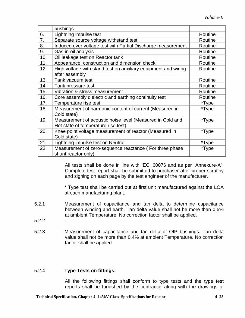
Volume-II
Technical Specification, Chapter 4- 145kV Class Specifications for Reactor 4- 28
bushings 6. Lightning impulse test Routine 7. Separate source voltage withstand test Routine 8. Induced over voltage test with Partial Discharge measurement Routine 9. Gas-in-oil analysis Routine 10. Oil leakage test on Reactor tank Routine 11. Appearance, construction and dimension check Routine 12. High voltage with stand test on auxiliary equipment and wiring
after assembly Routine
13. Tank vacuum test Routine 14. Tank pressure test Routine 15. Vibration & stress measurement Routine 16. Core assembly dielectric and earthing continuity test Routine 17. Temperature rise test *Type 18. Measurement of harmonic content of current (Measured in
Cold state) *Type
19. Measurement of acoustic noise level (Measured in Cold and Hot state of temperature rise test)
*Type
20. Knee point voltage measurement of reactor (Measured in Cold state)
*Type
21. Lightning impulse test on Neutral *Type22. Measurement of zero-sequence reactance ( For three phase
shunt reactor only) *Type
All tests shall be done in line with IEC: 60076 and as per “Annexure-A”. Complete test report shall be submitted to purchaser after proper scrutiny and signing on each page by the test engineer of the manufacturer.
* Type test shall be carried out at first unit manufactured against the LOA at each manufacturing plant.
5.2.1 Measurement of capacitance and tan delta to determine capacitance
between winding and earth. Tan delta value shall not be more than 0.5% at ambient Temperature. No correction factor shall be applied.
5.2.2 . 5.2.3 Measurement of capacitance and tan delta of OIP bushings. Tan delta
value shall not be more than 0.4% at ambient Temperature. No correction factor shall be applied.
5.2.4 Type Tests on fittings:
All the following fittings shall conform to type tests and the type test reports shall be furnished by the contractor along with the drawings of

Volume-II
Technical Specification, Chapter 4- 145kV Class Specifications for Reactor 4- 29
equipment/ fittings as per the clause no. 9.2 of the Section – GTR. The list of fittings and the type test requirement is:
1) Bushing (Type Test as IEC: 60137) 2) Buchholz relay (Type Test and protection test IP-55 of IEC 60529 on
terminal box)
3) Control cabinet (IP-55 test)
4) Pressure Relief device Test
The pressure Relief Device of each size shall be subjected to increase in oil pressure. It shall operate before reaching the test pressure specified in reactor tank pressure test. The operating pressure shall be recorded. The device shall seal off after excess pressure has been released. The terminal box / boxes of PRD should conform to degree of protection as per IP-55 of IEC 60529
5) Magnetic Oil Level gauge & Terminal Box for IP-55 degree of protection.
6) Air Cell (Flexible air separator) – Oil side coating, Air side under
Coating, Air side outer coating and coated fabric as per BS: 903.
7) OTI & WTI – Switch setting & operation, switch differential, switch rating.
55..22..44 PPrree--SShhiippmmeenntt CChheecckkss aatt MMaannuuffaaccttuurreerr''ss WWoorrkkss
5.2.4.1 Check for interchangeability of components of similar reactors for
mounting dimensions.
5.2.4.2 Check for proper packing and preservation of accessories like radiators, bushings, dehydrating breather, rollers, buchholz relay, fans, control cubicle, connecting pipes, conservator etc.
5.2.4.3 Check for proper provision for bracing to arrest the movement of core and
winding assembly inside the tank.
5.2.4.4 Gas tightness test to confirm tightness.
5.2.4.5 Derivation of leakage rate and ensure the adequate reserve gas capacity.
5.2.4.6 Measure and record the dew point of dry air /Nitrogen at the time of filling and after 24 hours in the reactor tank. Dew point of dry air / nitrogen at the
Volume-II
Technical Specification, Chapter 4- 145kV Class Specifications for Reactor 4- 30
time of reactor despatch should be better than (-) 30 deg C. Also the dew point of dry air / nitrogen cylinders attached for make up during transportation should of the order of (-) 50 deg C.
5.2.4.7 Functioning of impact recorder(s) at their works before installing on the
tank. 55..33 IInnssppeeccttiioonn aanndd TTeessttiinngg aatt SSiittee
The Contractor/Manufacturer shall carry out a detailed inspection and testing programme for field activities covering areas right from the receipt of material stage upto commissioning stage. An indicative programme of inspection as envisaged by the Employer is given below and in the document No. D-2-01-03-01-01 (or latest revision) (Pre-commissioning Procedures and Formats for substation bay equipment), which will be available in the respective sites and shall be referred by the contractor. However, it is contractor's responsibility to draw up and carry out such a programme duly approved by the Employer. Testing of oil sample at site shall be carried out as per Cl 3.4 above
55..33..11 RReecceeiipptt aanndd SSttoorraaggee CChheecckkss 5.3.1.1 Check and record condition of each package, visible part of the reactors
etc. for any damage.
5.3.1.2 Check and record the gas pressure in the reactor tank as well as in the cylinder. Measure and record the dew point of dry air /nitrogen in the reactor tank.
5.3.1.3 Visual check for wedging of core and coils before filling up with oil and also
check for condition of core and winding in general. 5.3.1.4 Check and record reading of impact recorders at receipt and verify the
allowable limits as per manufacturer's recommendation.
55..33..22 IInnssttaallllaattiioonn CChheecckkss
5.3.2.1 Check the whole assembly for tightness, general appearance & winding healthiness etc.
5.3.2.2 Oil leakage test
5.3.2.3 Visual check for Leakage on bushing before erection.
5.3.2.4 Measurement of capacitance and tan delta of the bushings before
fixing/connecting to the reactor. Contractor shall furnish these values for site reference.

Volume-II
Technical Specification, Chapter 4- 145kV Class Specifications for Reactor 4- 31
5.3.2.5 Measure and record the dew point of nitrogen in the main tank before
assembly. Manufacturer shall submit dew point acceptable limits along with temperature correction factor and shall for part of instruction manual. In case dew point values are not within permissible limit suitable drying out process shall be applied for dry out of active part in consultation with the Manufacturer.
5.3.2.6 Oil filling 5.3.2.6.1 Oil impregnation or drying under vacuum at site shall be done with the
transformer and oil at a temperature not exceeding 70 deg C. 5.3.2.6.2 The duration of the vacuum treatment shall be demonstrated as adequate
by means of water measurement with a cold trap or other suitable method. The vacuum shall be measured on the top of the transformer tank and should be less than 1mbar.
5.3.2.6.3 Vacuum shall not be broken until the reactor is oil filled up to the Buchholz
relay. Whenever the active insulation or any paper insulated HV connections, especially those from the windings to the bushings are exposed, these shall be re-impregnated under vacuum along with the complete reactor. For this purpose the reactor shall first be drained to expose all insulation material.
5.3.2.6.4 The minimum safe level of oil filling (if different from the Buchholz level) to
which the reactor shall be oil filled under vacuum, shall be indicated in the manual.
5.3.2.6.5 Procedures for site drying, oil purification, oil filling etc shall be submitted
for approval and complete instructions shall form part of the manual.
55..33..33 Commissioning Checks 5.3.3.1 Check the colour of silicagel breather.
5.3.3.2 Check the oil level in the breather housing, conservator tank, cooling system, condenser bushing etc.
5.3.3.3
5.3.3.4 Check the bushings for conformity of connection to the line etc.
5.3.3.5 Check for correct operation of all protection devices and alarms.
i) Buchholz relay
ii) Excessive winding temperature

Volume-II
Technical Specification, Chapter 4- 145kV Class Specifications for Reactor 4- 32
iii) Excessive oil temperature
iv) Low oil level indication 5.3.3.6 Check for adequate protection of electric circuit supplying the accessories.
5.3.3.7 Insulation resistance measurement for :
i) Control wiring ii) Main winding iii) Bushing current transformer 5.3.3.8 2kV/minute test between bushing CT terminal and earth.
5.3.3.9 Check for cleanliness of the reactor and the surrounding.
5.3.3.10 Measure vibration and noise level
5.3.3.11 DGA of oil sample just before commissioning and after 24 hours of
commissioning.
5.3.3.12 Capacitance and tan delta measurement of winding & bushing.
5.3.3.13 Frequency Response Analysis (FRA) at site (For 245 kV class Reactor
only) by using owner’s equipment which shall be provided free of cost.
5.3.3.14 Contractor shall prepare a comprehensive commissioning report including
all commissioning test results and forward to Employer for future record. 6 Technical Parameters
6.1 Shunt Reactor of 145 kV class 25 MVAR Three phase
6.1.1 Rated Voltage
145kV (1.0pu)

Volume-II
Technical Specification, Chapter 4- 145kV Class Specifications for Reactor 4- 33
6.1.2 Applicable standard IEC 60076-6
6.1.3 System Fault level 31.5kA
6.1.4 Connection Star with neutral brought out
6.1.5 Insulation level (for winding)
(a) Lightning impulse 1.2/50 µsec withstand voltage
550 kVp
6.1.6 Maximum temp rise over an ambient temp of 50 deg C and at 145kV voltage
(a) of winding measured by resistance method
45 deg C
(b) of top oil measured thermometer
40 deg C
(c) The temperature of the hottest spot
Shall be as per relevant standards.
6.1.7 Cooling System Natural Oil circulation (ONAN)
6.1.8 Insulation level of neutral
(a) Impulse withstand voltage 170 kVp
(b) Power frequency voltage 70 kV (rms)
(c) Whether neutral is to be brought out
Yes (through 36kV class solid core bushing
6.1.9 Ratio of zero sequence reactance to positive reactance (X0/X1)
between 0.9 & 1.0
6.1.10 Range of constant impedance Upto 1.4 pu voltage (the bidder shall furnish complete saturation characteristics of the Reactors up to 2.5 pu Voltage
6.1.11 Tolerance on current 0 to +5%
6.1.12 Harmonic content in phase current The crest value of the third harmonic component in phase current not to exceed 3% of the crest value of fundamental when reactor is energised at rated voltage with

Volume-II
Technical Specification, Chapter 4- 145kV Class Specifications for Reactor 4- 34
sinusoidal wave form
6.1.13 Permissible current unbalance among different phases
+ 2%
6.1.14 Minimum clearance in air
Rated voltage
Phase to phase
Phase to ground
145 kV 1220 mm 1050 mm
6.1.15 Noise level at rated voltage and frequency
: 75 dB
6.1.16 Bushing Line side Neutral side
(a) Rated voltage 145 kV 36 kV
(b) Creepage distance (total) 3625 mm 900 mm
(c) Mounting Tank cover Tank cover (d) 1.2/50 microsec. Lightning
impulse withstand voltage (kVp) 650 170
(e) One minute power frequency with stand voltage (kV rms)
305 77
(f) Rated current (A) 800 800
6.1.17 Vibration and stress level Not more than 200 microns peak to peak at rated voltage and frequency Average vibrations shall not exceed 60 microns peak to peak. Tank stresses shall not exceed 2.0kg/sq.mm at any point on the tank.
6.1.18 Maximum Partial Discharge 100 pC (PD) level at 1.5 pu
7.0 Bushing Current Transformer 7.1 Current transformers shall comply with IEC-60185. 7.2 It shall be possible to remove the turret mounted current transformers from
the reactor tank without removing the tank cover. Necessary precautions

Volume-II
Technical Specification, Chapter 4- 145kV Class Specifications for Reactor 4- 35
shall be taken to minimize eddy currents and local heat generated in the turret.
7.3 Current transformer secondary leads shall be brought out to a weather
proof terminal box near each bushing. These terminals shall be wired out to cooler control cabinet/ marshalling box using separate cables for each core.
7.4 Bushing Current transformer parameters indicated in this specification are
tentative and liable to change within reasonable limits. The Contractor shall obtain Employer's approval before proceeding with the design of bushing current transformers.
7.5 Technical Parameters 7.5.1 Current Transformer Parameters for 145 kV Shunt Reactor (on each
phase connection)
Line side
Core 1 Core 2 Core 3(i) Ratio 200/1A 200/1A 200/1A (ii) Accuracy class PS PS PS (iii) Minimum knee point
voltage(volts) 200 200 200
(iv) Maximum secondary resistance (ohms)
1.0 1.0 1.0
(v) Exciting current(max.) at 50V
60mA 60mA 60mA
(vi) Function Differential protection(High impedance)
Restricted Earth fault protection
Backup impedance protection
Neutral side
Core 4 Core 5 Core 6 Core CW (i) Ratio 200/1A 200/1A 200/1A Suitable for
WTI
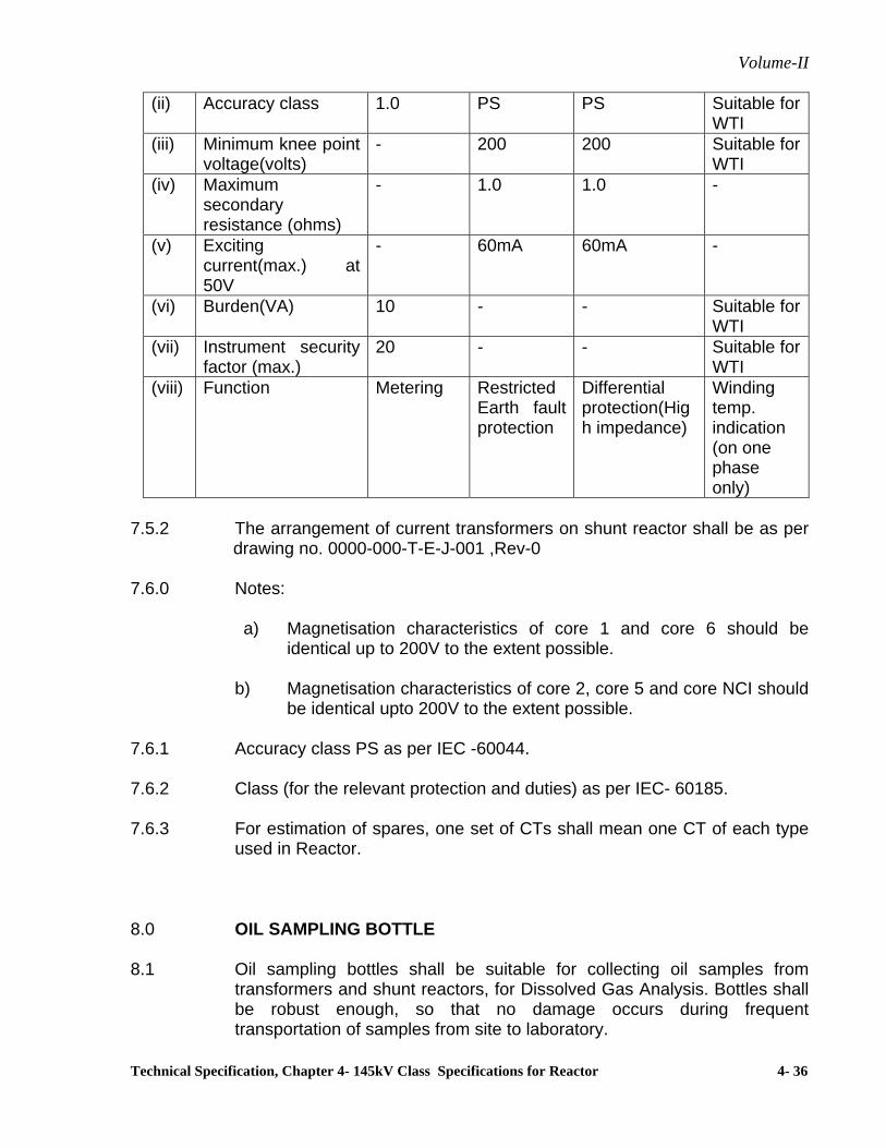
Volume-II
Technical Specification, Chapter 4- 145kV Class Specifications for Reactor 4- 36
(ii) Accuracy class 1.0 PS PS Suitable for WTI
(iii) Minimum knee point voltage(volts)
- 200 200 Suitable for WTI
(iv) Maximum secondary resistance (ohms)
- 1.0 1.0 -
(v) Exciting current(max.) at 50V
- 60mA 60mA -
(vi) Burden(VA) 10 - - Suitable for WTI
(vii) Instrument security factor (max.)
20 - - Suitable for WTI
(viii) Function Metering Restricted Earth fault protection
Differential protection(High impedance)
Winding temp. indication (on one phase only)
7.5.2 The arrangement of current transformers on shunt reactor shall be as per
drawing no. 0000-000-T-E-J-001 ,Rev-0 7.6.0 Notes:
a) Magnetisation characteristics of core 1 and core 6 should be identical up to 200V to the extent possible.
b) Magnetisation characteristics of core 2, core 5 and core NCI should
be identical upto 200V to the extent possible. 7.6.1 Accuracy class PS as per IEC -60044. 7.6.2 Class (for the relevant protection and duties) as per IEC- 60185. 7.6.3 For estimation of spares, one set of CTs shall mean one CT of each type
used in Reactor. 8.0 OIL SAMPLING BOTTLE 8.1 Oil sampling bottles shall be suitable for collecting oil samples from
transformers and shunt reactors, for Dissolved Gas Analysis. Bottles shall be robust enough, so that no damage occurs during frequent transportation of samples from site to laboratory.

Volume-II
Technical Specification, Chapter 4- 145kV Class Specifications for Reactor 4- 37
8.2 Oil sampling bottles shall be made of stainless steel having a capacity of
one litre. 8.3 Oil Sampling bottles shall be capable of being sealed gas-tight and shall
be fitted with cocks on both ends. 8.4 The design of bottle & seal shall be such that loss of hydrogen shall not
exceed 5% per week. 8.4.1 An impermeable oil-proof, transparent plastic or rubber tube of about 5
mm diameter, and of 01 meter length shall also be provided with each bottle along with suitable connectors to fit the tube on to the oil sampling valve of the equipment and the oil collecting bottles respectively.
99..00 OOiill SSyyrriinnggee
The glass syringe and three way stop cock valve shall meet the following specification
Dimensions
The tentative dimensions are given below Volume 50 ml ± 1.5 % Piston outside diameter 27.45 ± 0.20 mm Barrel Diameter (OD) 32.35 ± 0.55 mm Barrel Diameter (OD) 44.00 ± 0.75 mm Barrel Diameter (OD) 34.05 ± 0.65 mm Length (L) 178.00 mm ± 0.50 mm Increment 2.0 ml
General The syringe shall be made from Heat resistant borosilicate Glass The material and construction should be resistant to breakage from shock and sudden temperature changes Reinforced at luer lock tip Centre and barrel base. The cylinder-Plunger fit is leak proof and shall meet the requirement of IEC-60567. Plunger shall be individually ground and fitted to barrel for smooth movement with no back flow. Barrel rim should be flat on both sides tom prevent rolling and should be wide enough for convenient finger tip grip. The syringe shall be custom fit and uniquely numbered for matching. The syringe shall be clearly marked with graduations of 2.0 ml and 10.0 ml and shall be permanently fused for life time legibility.
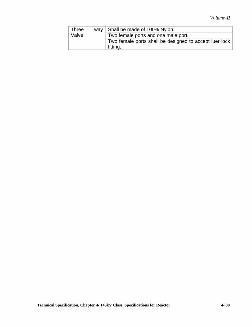
Volume-II
Technical Specification, Chapter 4- 145kV Class Specifications for Reactor 4- 38
Three way Valve
Shall be made of 100% Nylon. Two female ports and one male port. Two female ports shall be designed to accept luer lock fitting.
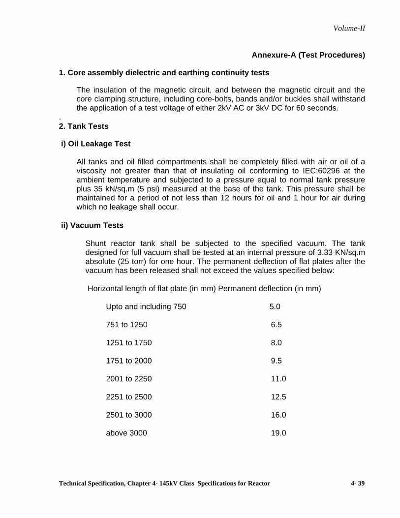
Volume-II
Technical Specification, Chapter 4- 145kV Class Specifications for Reactor 4- 39
Annexure-A (Test Procedures)
1. Core assembly dielectric and earthing continuity tests
The insulation of the magnetic circuit, and between the magnetic circuit and the core clamping structure, including core-bolts, bands and/or buckles shall withstand the application of a test voltage of either 2kV AC or 3kV DC for 60 seconds.
. 2. Tank Tests i) Oil Leakage Test
All tanks and oil filled compartments shall be completely filled with air or oil of a viscosity not greater than that of insulating oil conforming to IEC:60296 at the ambient temperature and subjected to a pressure equal to normal tank pressure plus 35 kN/sq.m (5 psi) measured at the base of the tank. This pressure shall be maintained for a period of not less than 12 hours for oil and 1 hour for air during which no leakage shall occur.
ii) Vacuum Tests Shunt reactor tank shall be subjected to the specified vacuum. The tank
designed for full vacuum shall be tested at an internal pressure of 3.33 KN/sq.m absolute (25 torr) for one hour. The permanent deflection of flat plates after the vacuum has been released shall not exceed the values specified below:
Horizontal length of flat plate (in mm) Permanent deflection (in mm) Upto and including 750 5.0 751 to 1250 6.5 1251 to 1750 8.0 1751 to 2000 9.5 2001 to 2250 11.0 2251 to 2500 12.5 2501 to 3000 16.0 above 3000 19.0

Volume-II
Technical Specification, Chapter 4- 145kV Class Specifications for Reactor 4- 40
iii) Pressure Test Shunt reactor tank of each size, its radiator, conservator vessel and other fittings
together or separately shall be subjected to an air pressure corresponding to twice the normal head of oil or normal pressure plus 35 KN/sq.m whichever is lower, measured at the base of the tank and maintained for one hour. The permanent deflection of the flat plate after the excess pressure has been released shall not exceed the figures specified above for vacuum test.
3. Temp. Rise Test as per IEC: 60076
Oil sample shall be drawn before and after heat run test and shall be tested for
dissolved gas analysis. Oil sampling to be done 2 hours prior to commencement of temperature rise test.
The acceptance norms with reference to various gas generation rates shall be
as per IEC 61181.
The test shall be done for a minimum of 24 hours with saturated temperature for at least 4 hours.
4. Routine tests on Bushings: Routine test on bushings shall be done as per IEC
60137.

Volume-II
Technical Specification, Chapter 5: Technical Data Sheet (Guaranteed Technical Particulars) 5- 1
Chapter 5
Technical Data Sheet (Guaranteed Technical Particulars)
A. Power Transformer
B. Reactor

Volume-II
Technical Specification, Chapter 5: Technical Data Sheet (Guaranteed Technical Particulars) 5- 2
Technical Data Sheet (Guaranteed Technical Particulars)
A. Power Transformer
S.N. Description Offered Data
220/132, 160 MVA
220/132, 100 MVA
220/33, 63 MVA
132/11, 10 MVA
1 Name of manufacturer 2 Normal full load single phase/three phase output:
H.V. Winding (KVA) L.V. Winding (KVA)
2.1 Temp. Rise as specified in the specification.
3 Continuous single phase/three phase output under, Site conditions as specified in the specification
H.V. Winding (KVA) L.V. Winding (KVA)
4 Type of cooling and corresponding normal Full load output
H.V. Winding (KVA) L.V. Winding (KVA)
5 Over load capacity (as per IS:6600) starting from Full load and with Temp. as specified in the Specification (KVA)
6 Normal ratio of transformation
7 Connection (including vector group reference & Symbol)
H. V. Winding L.V. Winding
8 Type of tap changer 9 Tapping
a) Number b) Range c) Location
10 Details of Automatic Voltage Regulator (a) Make (b) Model etc. (c) Short description (other)
11 Type of core construction 12 i) Temp. rise by resistance of winding (ºC)
ii) Temp. rise in oil by thermometer (ºC)
iii) Hot spot temp. for which the transformer is designed (ºC)
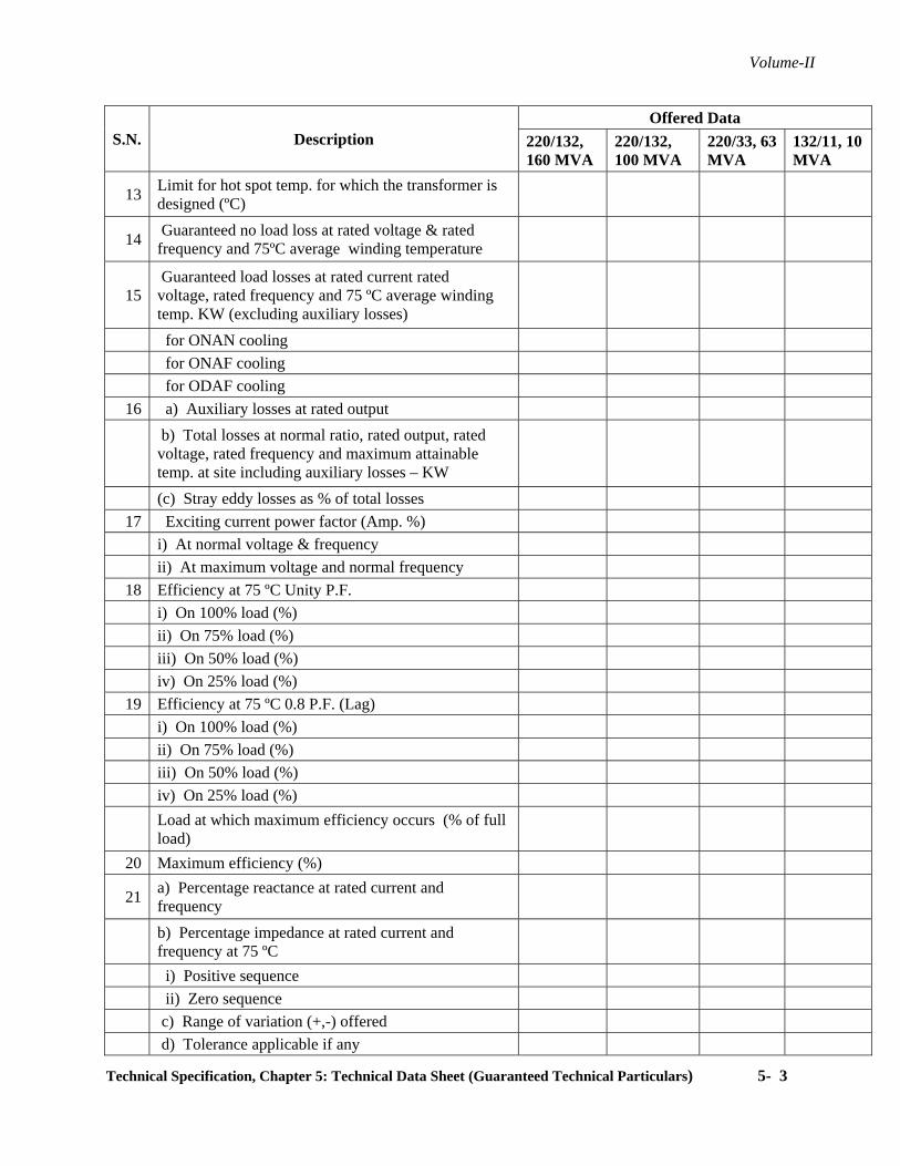
Volume-II
Technical Specification, Chapter 5: Technical Data Sheet (Guaranteed Technical Particulars) 5- 3
S.N. Description Offered Data
220/132, 160 MVA
220/132, 100 MVA
220/33, 63 MVA
132/11, 10 MVA
13 Limit for hot spot temp. for which the transformer is designed (ºC)
14 Guaranteed no load loss at rated voltage & rated frequency and 75ºC average winding temperature
15 Guaranteed load losses at rated current rated voltage, rated frequency and 75 ºC average winding temp. KW (excluding auxiliary losses)
for ONAN cooling for ONAF cooling for ODAF cooling
16 a) Auxiliary losses at rated output
b) Total losses at normal ratio, rated output, rated voltage, rated frequency and maximum attainable temp. at site including auxiliary losses – KW
(c) Stray eddy losses as % of total losses 17 Exciting current power factor (Amp. %)
i) At normal voltage & frequency ii) At maximum voltage and normal frequency
18 Efficiency at 75 ºC Unity P.F. i) On 100% load (%) ii) On 75% load (%) iii) On 50% load (%) iv) On 25% load (%)
19 Efficiency at 75 ºC 0.8 P.F. (Lag) i) On 100% load (%) ii) On 75% load (%) iii) On 50% load (%) iv) On 25% load (%)
Load at which maximum efficiency occurs (% of full load)
20 Maximum efficiency (%)
21 a) Percentage reactance at rated current and frequency
b) Percentage impedance at rated current and frequency at 75 ºC
i) Positive sequence ii) Zero sequence c) Range of variation (+,-) offered d) Tolerance applicable if any

Volume-II
Technical Specification, Chapter 5: Technical Data Sheet (Guaranteed Technical Particulars) 5- 4
S.N. Description Offered Data
220/132, 160 MVA
220/132, 100 MVA
220/33, 63 MVA
132/11, 10 MVA
22 Impedance voltage drop at normal ratio at 75ºC expressed as a percentage of normal voltage on full load (%)
23 Regulation on full load at unity P.F. at 75 ºC expressed as a percentage of normal voltage (%)
24 Regulation on full load 0.8 P.F. lagging at 75ºC expressed as a percentage in the winding
25 Maximum current density & c/s area in the winding (Guaranteed and As per SC calculation)
i) H.V. (Amp./Sq. cm.) ii) Cross sectional area iii) L.V. (Amp/Sq. cm) iv) Cross sectional area
26 Maximum flux density in the core 26.a Core details i) Material of core lamination ii) Thickness of core plates (mm) iii) Insulation of core lamination iv) Insulation of core clamping plates v) Press board material & thickness vi) Prime quality grade
27 Core joints (butt or inter leave) 28 Type of winding
i) H.V. ii) L.V.
29 Type of radial support i) High Voltage Winding ii) Lower Voltage Winding
30 Insulation of higher voltage winding 31 Insulation of lower voltage winding 32 Thickness of transformer tank plates
i) Sides (mm) ii) Bottom (mm) iii) Cover (mm) iv) Radiator (mm)
33 (A) POWER FREQUENCY WITHSTAND VOLT
i) Test voltage for 1 min. P.F. withstand test on live end of high voltage winding (KV rms)

Volume-II
Technical Specification, Chapter 5: Technical Data Sheet (Guaranteed Technical Particulars) 5- 5
S.N. Description Offered Data
220/132, 160 MVA
220/132, 100 MVA
220/33, 63 MVA
132/11, 10 MVA
ii) Test voltage for 1 min. P.F. withstand test on neutral end of high voltage winding (KV rms)
iii) Test voltage for 1 min. P.F. withstand test on live end of low voltage winding (KV rms)
(B) IMPULSE TEST
i) Test voltage for 1.2/50 micro sec. Full wave withstand test on high voltage winding (KV crest) on
ii) Test voltage for 1.2/50 micro sec. Full wave withstand test on low voltage winding (KV crest) on
34 Inter-turn Insulation i) Extent of end turns reinforcement ii) Extent of reinforcement of turns adjustment to tap
iii) Test voltage for 1 min. 50 Hz. Inter-turn insulation test on (i) (KV rms)
iv) Test voltage for 1 min. 50 Hz. inter-turn insulation test on (ii) (KV rms)
v) Test voltage for 1 min. 50 Hz. inter-turn insulation test on main body of the winding (KV rms)
35 Type of winding temperature indicator Maxi continuous ratings i) At 50 C ambient air temp. at site (KVA) ii) At 40 C ambient air temp. at site (KVA) iii) At 30 C ambient air temp. at site (KVA) iii) At 20 C ambient air temp. at site (KVA)
37 Details of Air cell Make Type Capacity Size
38 Width of track gauge (Meters) 39 Bushing Particulars
(a) HV Bushing
i) Type of high voltage bushing and creepage distance in mm
ii) Rated current iii) STC rating for 3 sec iv) Weight of high voltage bushing in Kg
v) Quantity of oil in one high voltage bushing Insulator, in litre

Volume-II
Technical Specification, Chapter 5: Technical Data Sheet (Guaranteed Technical Particulars) 5- 6
S.N. Description Offered Data
220/132, 160 MVA
220/132, 100 MVA
220/33, 63 MVA
132/11, 10 MVA
vi) Dry 1 minute power frequency test voltage value of high voltage bushing in KV
vii) Wet 10 second power frequency test voltage value of high voltage bushing in KV
viii) Impulse withstand test voltage value with 1.2/50 microsecond full wave of high voltage bushing in KV
(b) LV Bushing
i) Type of low voltage bushing and creepage distance in mm
ii) Rated current iii) STC rating for 3 sec iv) Weight of low voltage bushing in Kg
v) Quantity of oil in one low voltage bushing Insulator, in litre
vi) Dry 1 minute power frequency test voltage value of low voltage bushing in KV
vii) Wet 10 second power frequency test voltage value of low voltage bushing in KV
viii) Impulse withstand test voltage value with 1.2/50 microsecond full wave of low voltage bushing in KV
(c) NEUTRAL Bushing
i) Type of low voltage bushing and creepage distance in mm.
ii) Rated current iii) Weight of bushing insulator in kg iv) Quantity of oil in one bushing in litres
v) Dry 1 minute power frequency withstand and test voltage value of bushing in KV
vi) Wet 10 second power frequency withstand test voltage value of bushing in KV
vii) Impulse withstand test voltage with 1.2/50 microsecond fall wave of bushing in KV
40 Clearance a) Minimum clearance between phase (Mtrs.) i) In oil ii) Out of oil
b) Minimum clearance of high voltage to earth in oil (Mtrs)

Volume-II
Technical Specification, Chapter 5: Technical Data Sheet (Guaranteed Technical Particulars) 5- 7
S.N. Description Offered Data
220/132, 160 MVA
220/132, 100 MVA
220/33, 63 MVA
132/11, 10 MVA
c) Minimum clearance of high voltage to tank in oil (Mtrs)
41 Net weight of the core (Kgs.) 42 Net weight of copper (Kgs.)
a) H.V. (Kgs.) b) L.V. (Kgs.) c) Total (Kgs.)
43 Weight of core and windings 44 Weight of fittings 45 Net untanking weight(Kgs.) 46 Weight of tank and cover (Kgs.)
46.1 Tank dimensions 46.2 Guarantee against leakage for 3 years
47 Weight of oil in transformer including bushings, conservator and cooling system (Kgs.)/Quantity (Ltrs.)
48 Weight of oil in transformer (including bushings) (Kgs)
49 Weight of complete transformer with oil and all fittings (Kgs.)
50 Weight of transformer with all fittings but without oil (Kgs.)
51 Weight of the package to be transported and dimensions
52 Dimensions of the transformers i) Maximum height upto top of bushings (Mtrs.) ii) Overall length (Mtrs.) iii) Overall width (Mtrs.)
53 Minimum clear height for lifting core and windings from tank in meters
54 Details of on load tap changing gear a) Make b) Type c) Rating i) Rated Voltage ii) Rated current iii) Step Voltage iv) STC rating d) Time for complete tap change (Sec.)

Volume-II
Technical Specification, Chapter 5: Technical Data Sheet (Guaranteed Technical Particulars) 5- 8
S.N. Description Offered Data
220/132, 160 MVA
220/132, 100 MVA
220/33, 63 MVA
132/11, 10 MVA
e) Diverter selector switch transition time (Cycles) f) Control g) Auxiliary supply details h) Voltage control i) Protection devices j) Value of Maxi. Short circuit current k) Maxi. Impulse withstand test voltage value with 1.2/50 microsecond full wave between switch and ground
l) Maxi. Impulse withstand test voltage value with 1.2/50 micro sec. Full wave between the remote terminal and ground with the selector terminal at one end of the range
m) Maxi. Power frequency test voltage between switch assembly and range
n) Maxi. Impulse withstand test voltage with 1.2/50 micro sec. across the tapping range
o) Maxi. Temp. of the tap changer which must not be exceeded during operation :
p) Approximate overall weight (kg) q) Approximate overall dimensions (Mtrs) r) Approximate overall quantity of oil (Kgs.)
55 No. of operations (approx.) after which the change of oil is necessary :
56 Any other particulars which need a mention 57 Cooling calculation shall be submitted 58 OIL LOAD TAPCHANGING GEAR
i) Make ii) Type designation iii) Suitable for auto/manual operation (YES / NO ) iv) Rated voltage (KV) v) Rated current (Amps) vi) Step voltage (Volts) vii) Number of steps viii) Rated voltage of drive motor (V) ix) List of routine tests to be carried out
x) Location of the taps with respect to the terminals of the tapped winding

Volume-II
Technical Specification, Chapter 5: Technical Data Sheet (Guaranteed Technical Particulars) 5- 9
S.N. Description Offered Data
220/132, 160 MVA
220/132, 100 MVA
220/33, 63 MVA
132/11, 10 MVA
xi) Drawing or pamphlet-number of the technical and descriptive particulars of the OLTC, enclosed with the Bid.
Signed ____________________ As representative for _________________________ Address _______________________________________ Date______________________________________

Volume-II
Technical Specification, Chapter 5: Technical Data Sheet (Guaranteed Technical Particulars) 5- 10
Technical Data Sheet (Guaranteed Technical Particulars)
B. 25 MVAR 145 kV Reactor
S.N. Description Offered Data 1 Name of manufacturer 2 Governing Standard 3 Type of reactor 4 Type of cooling 5 Connection 6 a) Reactive power for continuous operation (MVAR)
I) At rated voltage II) At highest voltage ( i.e. 5% higher than rated) (MVAR) b) Rated voltage c) Temperature rise in oil above ambient temp. ºC
d) Temperature rise of winding by resistance above ambient temperature ºC
e) Rated frequency (Hz) 7 Number of Phases
8 a) Guaranteed losses at rated voltage and frequency at rated output and at 75ºC average winding temperature (KW)
b) Tolerance on above losses (%)
9 Guaranteed max. losses at rated voltage and frequency at rated output at its percentage
10 Impedance : a) Positive sequence (Ohms) b) Zero sequence (Ohms)
11 Ratio of reactor ( i.e. Q-factor)
12 Maximum remissible duration of service at 110% of rated voltage, starting from cold without exceeding permissible temperature rise(hrs.)
13 Noise level and reference standard (db). 14 Test voltage (for winding)
a) ightning impulse (1.2/50 micro-seconds) withstand voltage (KV peak)
b) Power frequency withstand voltage (KV rms.) c) Switching surge withstand voltage (KV peak)
15 Clearances: a) HV phase to Phase (mm) b) Phase to Ground (mm) c) Neutral to Ground (mm)
16 Approximate weights (kgs.) a. Core (kgs.)

Volume-II
Technical Specification, Chapter 5: Technical Data Sheet (Guaranteed Technical Particulars) 5- 11
S.N. Description Offered Data b. Winding (kgs.) c. Tank and fittings(kgs.) d. Oil (kgs.) e. Total weight (kgs.) f. Untanking weight (kgs.) (to provide access to core and coils)
17 Quantity of oil (including 10% extra) itars. 18 Conservator
a) Total volume b) Volume between highest and lowest visible oil levels.
19 (a) Size of largest package (mm x mm x mm) (b) Weight of largest package (kgs.) (c) Gross weight to be handled (kgs.) (d) Gross volume to be handled (M3)
20 Bushing as per IS : 2099 a) Type b) Maker's name and country of Manufacturer c) Momentary power Frequency withstand voltage d) One minute power frequency withstanding voltage i) Dry (KV) ii) Wet (KV) e) Power Frequency puncture voltage (KV) (d) Full wave impulse withstand and voltage (KV) (f) Impulse puncture voltage (KV) (h) Total creepage distance in air (i) Weight and dimensions of assembled Bushings. (KV)
21 Core a) Type of core b) Justification for type of core adopted c) Technical details of the core i) Material ii) Thickness in mm iii) Grade (Prime only) iv) Insulation of core lamination v) Press board material and thickness
22 Zero Sequence Reactance/ positive sequence reactance i.e. XO/XI
23 Range of voltage up to which impedance will be constant and magnetization curve up to 2.5 pu. Voltage.
24. Vibration level
25. Amount of unbalanced current in each phase whenconnected to symmetrical voltages.
26. Lifting jacks (mechanical screw jacks)

Volume-II
Technical Specification, Chapter 5: Technical Data Sheet (Guaranteed Technical Particulars) 5- 12
S.N. Description Offered Data a) Governing standards b) Number of Jacks included in one set. c) Type and make. d) Capacity e) Pitch f) Lift h) Mean diameter of thread
27 Capacitance value (Phase to Ground) 28 Type of oil preservation system 29 Harmonic content in Phase current
30 Quality of oil (please enclose separate sheet for characteristics of oil)
31 Cooling calculation shall be submitted
Signed ____________________ As representative for _________________________ Address _______________________________________ Date______________________________________

Volume-II
Technical Specification, Chapter 5: Technical Data Sheet (Guaranteed Technical Particulars) 5- 13
Statement of Deviation from Bid Specifications:
A. Power Transformer and accessories ( For each rating separately) B. Reactor and accessories