ndx matthews
DESCRIPTION
kkTRANSCRIPT
Overview of Shale Gas Stimulation Techniques*
H. Lee Matthews1
Search and Discovery Article #40335 (2008) Posted November 11, 2008
*Adapted from oral presentation at AAPG Annual Convention, San Antonio, Texas, April 20-23, 2008
1Cornerstone N.G. Engineering, LP, Fort Worth, TX ([email protected])
Abstract While shale gas has been produced in the United States for well over 100 years beginning with the Devonian Shale in the Appalachian region, explosive growth in shale gas development has occurred over the last ten years. Shale gas reservoirs represent the nation’s most significant natural gas resource which is currently economic, and they are expected to provide a substantial part of our natural gas supplies over the next 50 years. Major technological breakthroughs such as 3D seismic and horizontal drilling have played a part in the exploitation of shale resources. Stimulation techniques have also evolved over this period, demonstrating a significant impact on a well’s ultimate performance and a resource play’s economic viability. Stimulation techniques developed in the Barnett Shale of North Texas have been very successful in expanding the play beyond its early area bounds. Keys to this success are based on an understanding of the geological setting, the mineralogical description of the shale, rock mechanical properties of the shale and its bounding layers both above and below, structural geology and offset activity around the well of interest. The specific conditions related to a tract of acreage are unique and adjustments to the well plan should be made accordingly. While success in stimulating the Barnett Shale of north Texas has become somewhat commonplace, other shale resource plays have demonstrated a variation of reservoir characteristics which have required alternative stimulation techniques. This presentation briefly reviews the evolution of stimulation practices in the Barnett Shale of North Texas and expands into the current efforts that are ongoing in the other major shale plays such as the Woodford in Oklahoma, the Woodford and Barnett in West Texas, the Fayetteville in Arkansas, the Devonian and New Albany in the Appalachian region, and the Floyd in Alabama.

2008 AAPG Annual ConventionOverview of Shale Gas Stimulation Techniques
H Lee MatthewsH. Lee MatthewsCornerstone N.G. Engineering, LP
Cornerstone N.G. Engineering, LP
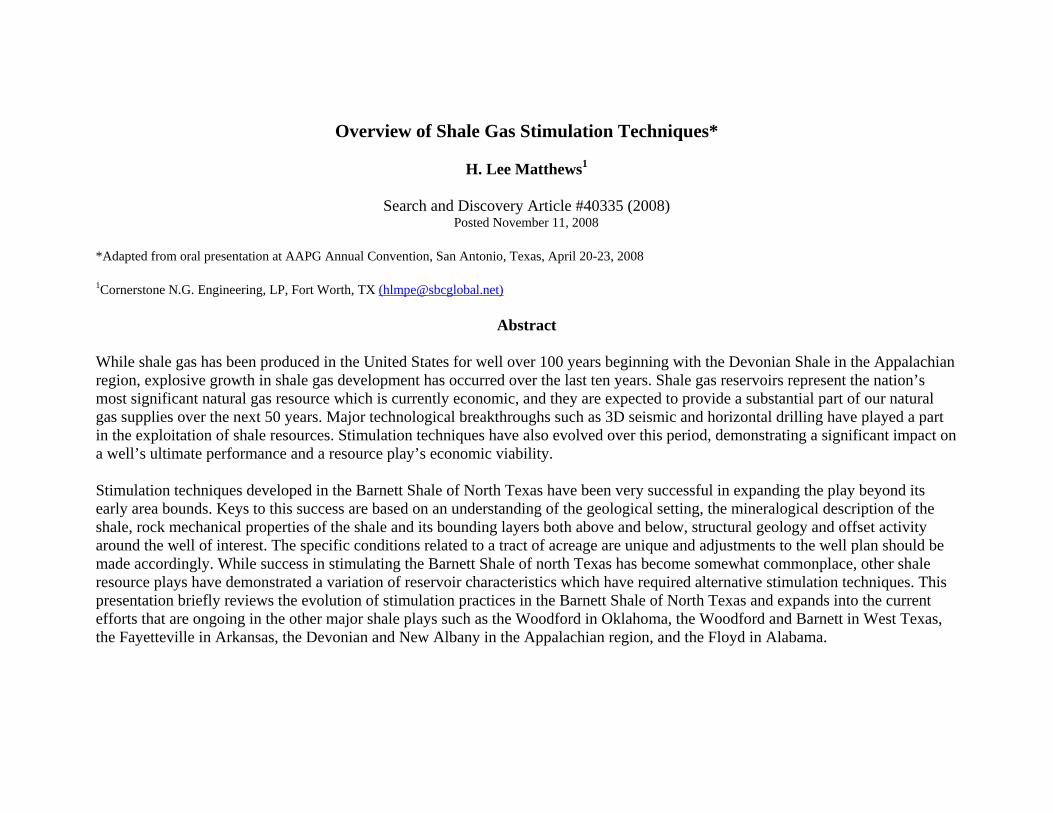
Common Questions
“What is so complicated about pumping water and sand?”
“How do you know what rate to pump at?” “How do you know what rate to pump at?”
“How do you control the direction of the frac?” How do you control the direction of the frac?
“Is simo-fracing really doing any good?g y g y g
“Why would anyone ever pump cross-linked gel again?”
“Does it matter where the lateral is placed for fracing”
Cornerstone N.G. Engineering, LP
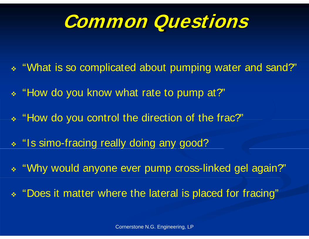
Geological Description
Geology - Stratigraphic and Structuralgy g pImpacts all phases of completion design
Shale thickness, composition, depositional environment
Bounding rock layers above and below for frac containment
Natural fractures – density, orientation, mineralization
Faulting, Karsts, formation dip and structural influences
f di tCornerstone N.G. Engineering, LP
on frac gradients
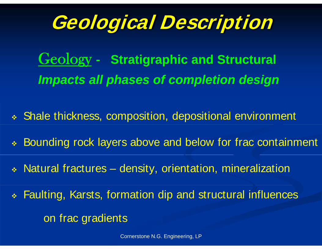
Goals for Shale Gas C l tiCompletions
Contact the maximum amount of reservoir surface area
fo p od ction pe fo mancefor production performance.
Contain the contact area to within the shale gas reservoir. Contain the contact area to within the shale gas reservoir.
Create geometrical pattern to develop the reservoir in
a consistent and predictable manner.
Optimize the completion design for economic results –
cost controls
Cornerstone N.G. Engineering, LP
cost controls.

Technological Milestones Early 1900’s: Shale gas becomes productive. N2 foam fracs
1983: Mitchell drills 1st Barnett Shale well: C W Slay No 1 1983: Mitchell drills 1 Barnett Shale well: C.W. Slay No. 1
80-90s: Evolution of X-linked gel technology in vertical wells
1991 1 t H i t l B tt ll MEC T P Si “B” 1H 1991: 1st Horizontal Barnett well MEC: T.P. Sims “B” 1H
Identified fracture azimuth – Max Principal stress
1996: Intro of slick water fracs (SWF) & Microseismic
1998: SW refracs of original gel fracs
2002: Horizontal laterals with multi-stage SWFs
2004: 3D seismic tool to avoid karsts and faultingg
2005: Shift focus to increasing recovery factor
2007: Multi well pads and cluster drilling
Cornerstone N.G. Engineering, LP
2007: Multi-well pads and cluster drilling

Vertical vs. Horizontal ?Vertical vs. Horizontal ?
Conside ations Considerations :
Total shale thickness
Number of segmented shale reservoirs
Frac barriers present and characterization
Depth of shale gas formation ept o s a e gas o at o
Stability of the shale target and overlying beds
Lease configuration and spacing requirements
Cornerstone N.G. Engineering, LP

Horizontal Development Planning
Surface use / pad sites
Wellbore layout Wellbore layout
Lateral spacing?
Drilling order
Completion order
Timing between completions Timing between completions
Load water recovery
Cornerstone N.G. Engineering, LP
y
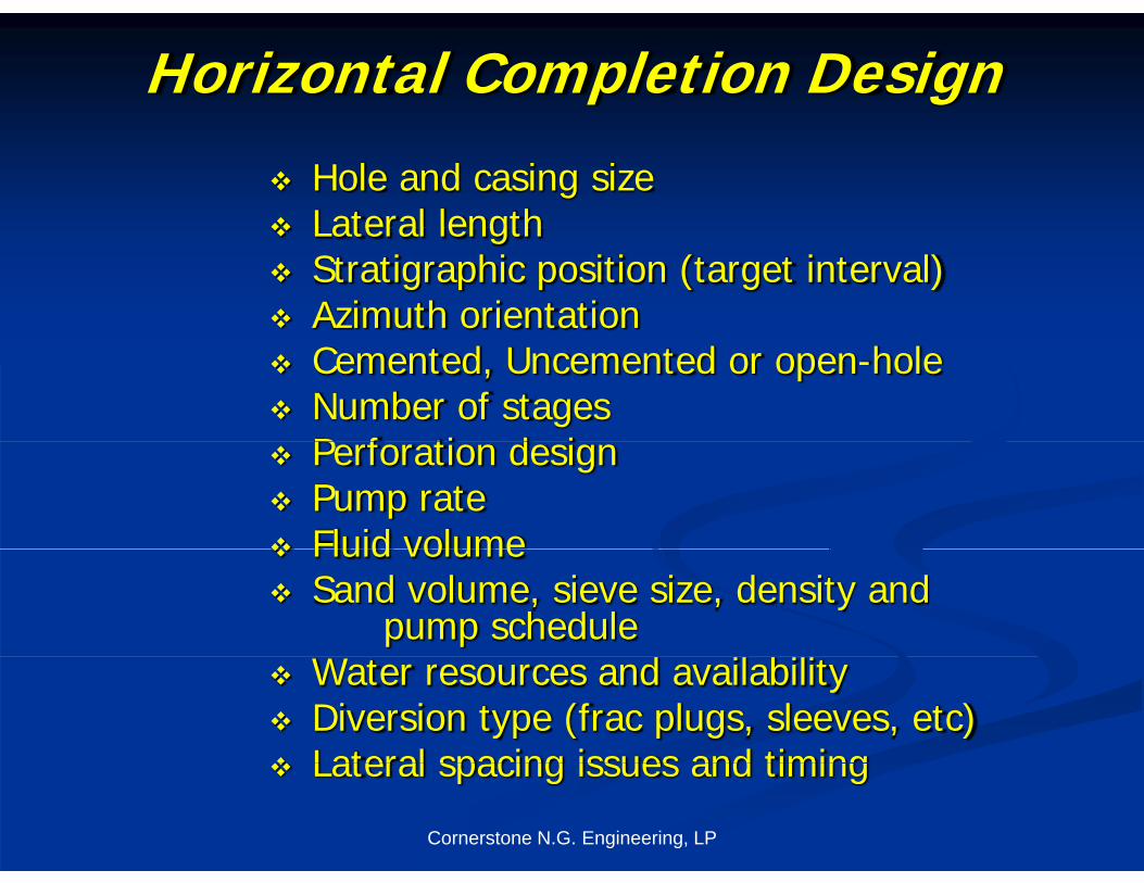
Horizontal Completion Design
Hole and casing size Lateral length Lateral length Stratigraphic position (target interval) Azimuth orientation Cemented, Uncemented or open-hole Number of stages
P f ti d i Perforation design Pump rate Fluid volume Fluid volume Sand volume, sieve size, density and
pump scheduled l b l Water resources and availability
Diversion type (frac plugs, sleeves, etc) Lateral spacing issues and timing
Cornerstone N.G. Engineering, LP
Lateral spacing issues and timing
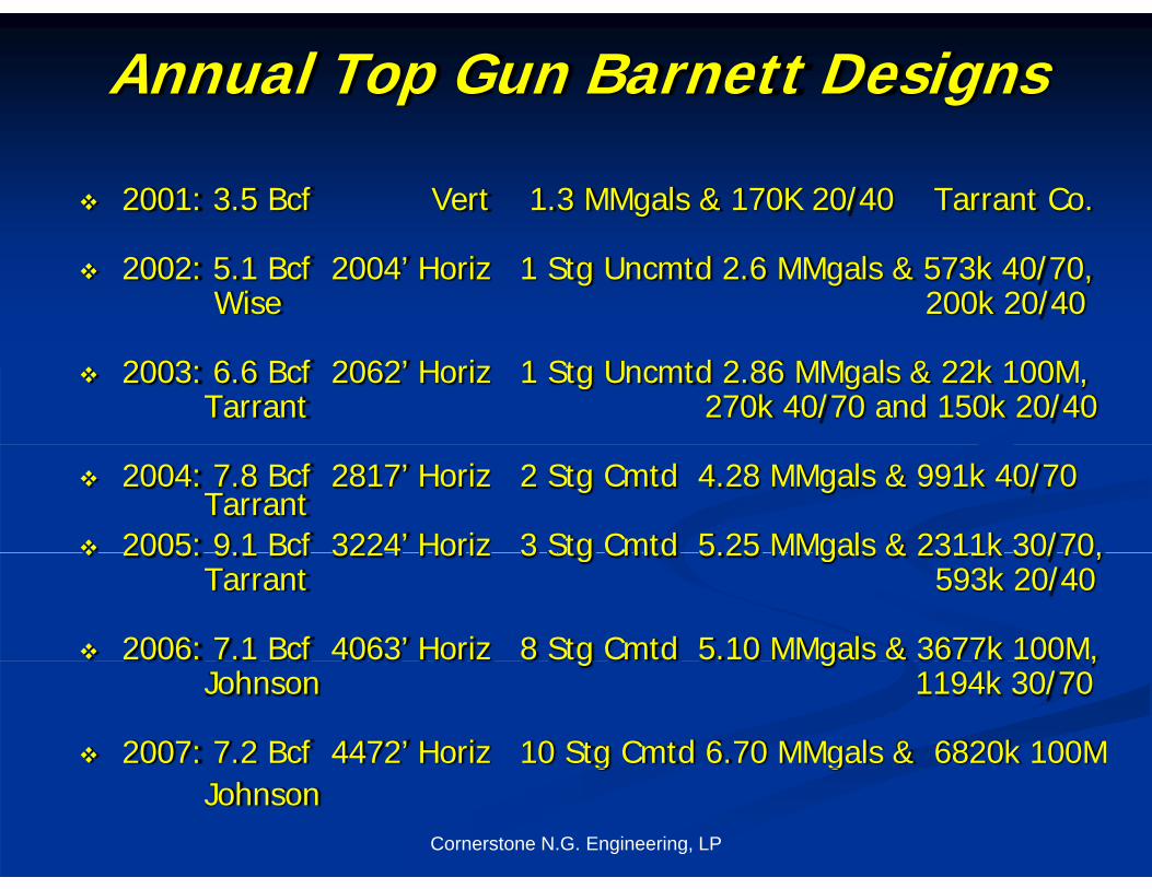
Annual Top Gun Barnett Designs
2001: 3.5 Bcf Vert 1.3 MMgals & 170K 20/40 Tarrant Co.
2002: 5.1 Bcf 2004’ Horiz 1 Stg Uncmtd 2.6 MMgals & 573k 40/70, Wise 200k 20/40
2003: 6.6 Bcf 2062’ Horiz 1 Stg Uncmtd 2.86 MMgals & 22k 100M, Tarrant 270k 40/70 and 150k 20/40
2004: 7.8 Bcf 2817’ Horiz 2 Stg Cmtd 4.28 MMgals & 991k 40/70Tarrant
2005: 9.1 Bcf 3224’ Horiz 3 Stg Cmtd 5.25 MMgals & 2311k 30/70, 2005: 9.1 Bcf 3224 Horiz 3 Stg Cmtd 5.25 MMgals & 2311k 30/70, Tarrant 593k 20/40
2006: 7.1 Bcf 4063’ Horiz 8 Stg Cmtd 5.10 MMgals & 3677k 100M,g g ,Johnson 1194k 30/70
2007: 7.2 Bcf 4472’ Horiz 10 Stg Cmtd 6.70 MMgals & 6820k 100M
Cornerstone N.G. Engineering, LP
g gJohnson

Birthplace of the Barnett – CW Slay
MontagueClay
Wise DentonJack
MontagueClay
ParkerTarrant
Palo PintoDallas
Johnson EllisHoodErath
Hill
Smrvl
Cornerstone N.G. Engineering, LP
Bosque
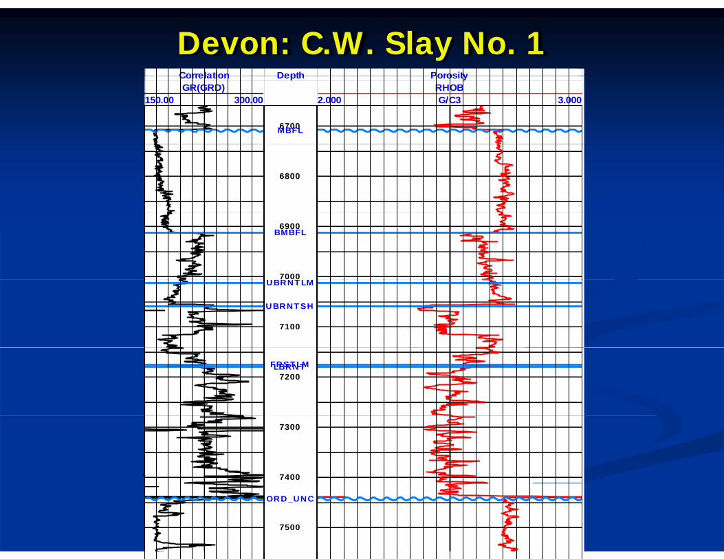
Devon: C.W. Slay No. 1Correlation Depth PorosityCorrelationGR(GRD)
150.00 300.00
Depth PorosityRHOB
2.000 3.000G/C3
6700MBFL
6800
6900
7000
BMBFL
UBRNT LM
7100
UBRNT LM
UBRNT SH
7200FRST LMLBRNT
7300
7400
Cornerstone N.G. Engineering, LP7500
ORD_UNC
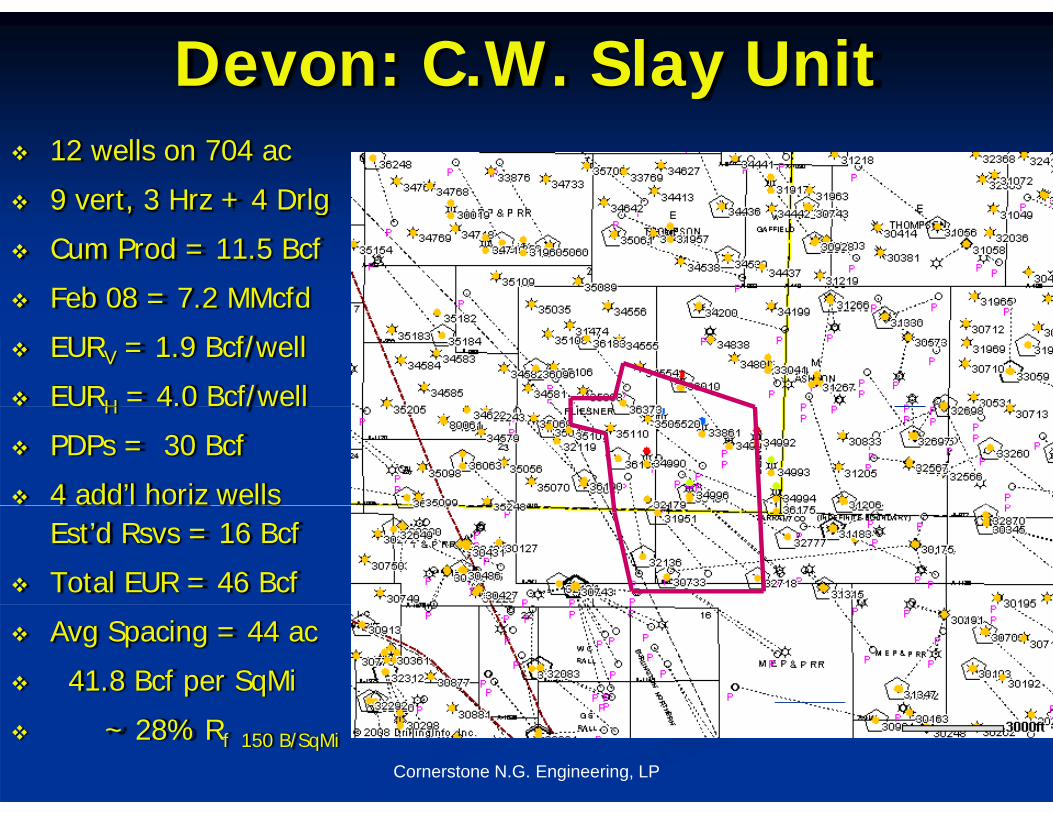
Devon: C.W. Slay Unit 12 wells on 704 ac
9 vert, 3 Hrz + 4 Drlg 9 vert, 3 Hrz 4 Drlg
Cum Prod = 11.5 Bcf
Feb 08 = 7.2 MMcfdeb 08 c d
EURV = 1.9 Bcf/well
EURH = 4.0 Bcf/wellH /
PDPs = 30 Bcf
4 add’l horiz wells Est’d Rsvs = 16 Bcf
Total EUR = 46 Bcf
Avg Spacing = 44 ac
41.8 Bcf per SqMi
Cornerstone N.G. Engineering, LP
~ 28% Rf 150 B/SqMi
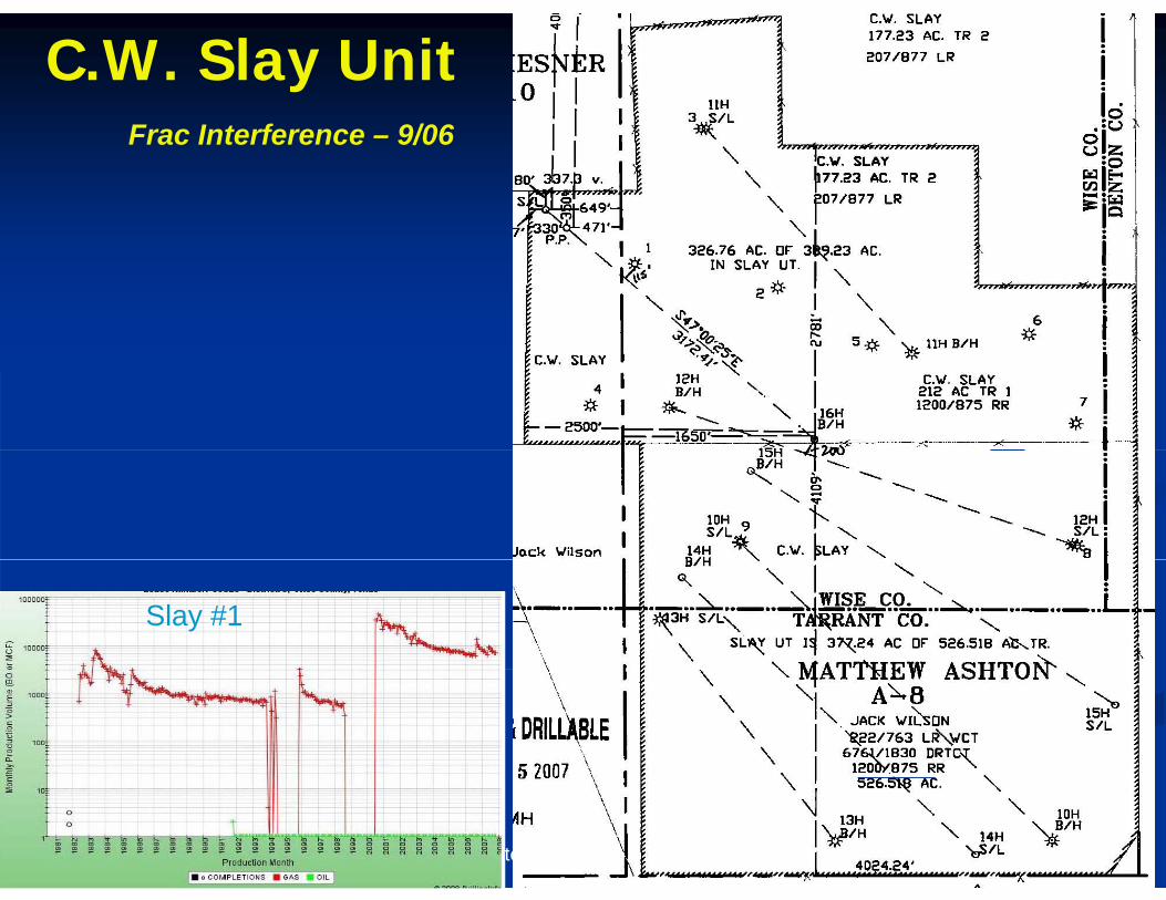
C.W. Slay UnitFrac Interference – 9/06
Slay #1
Cornerstone N.G. Engineering, LP
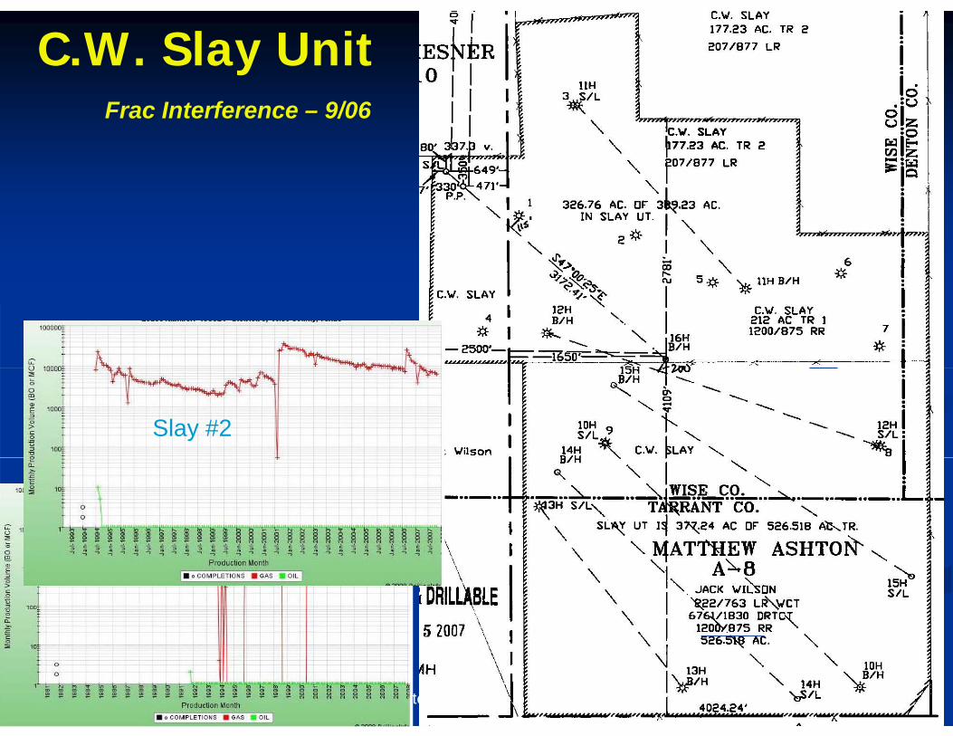
C.W. Slay UnitFrac Interference – 9/06
Slay #2
Slay #1
Cornerstone N.G. Engineering, LP
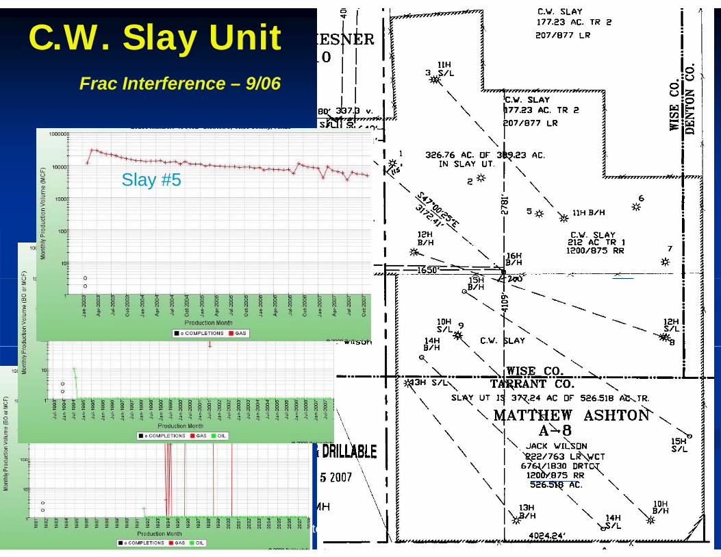
C.W. Slay UnitFrac Interference – 9/06
Slay #5
Slay #2
Slay #1
Cornerstone N.G. Engineering, LP
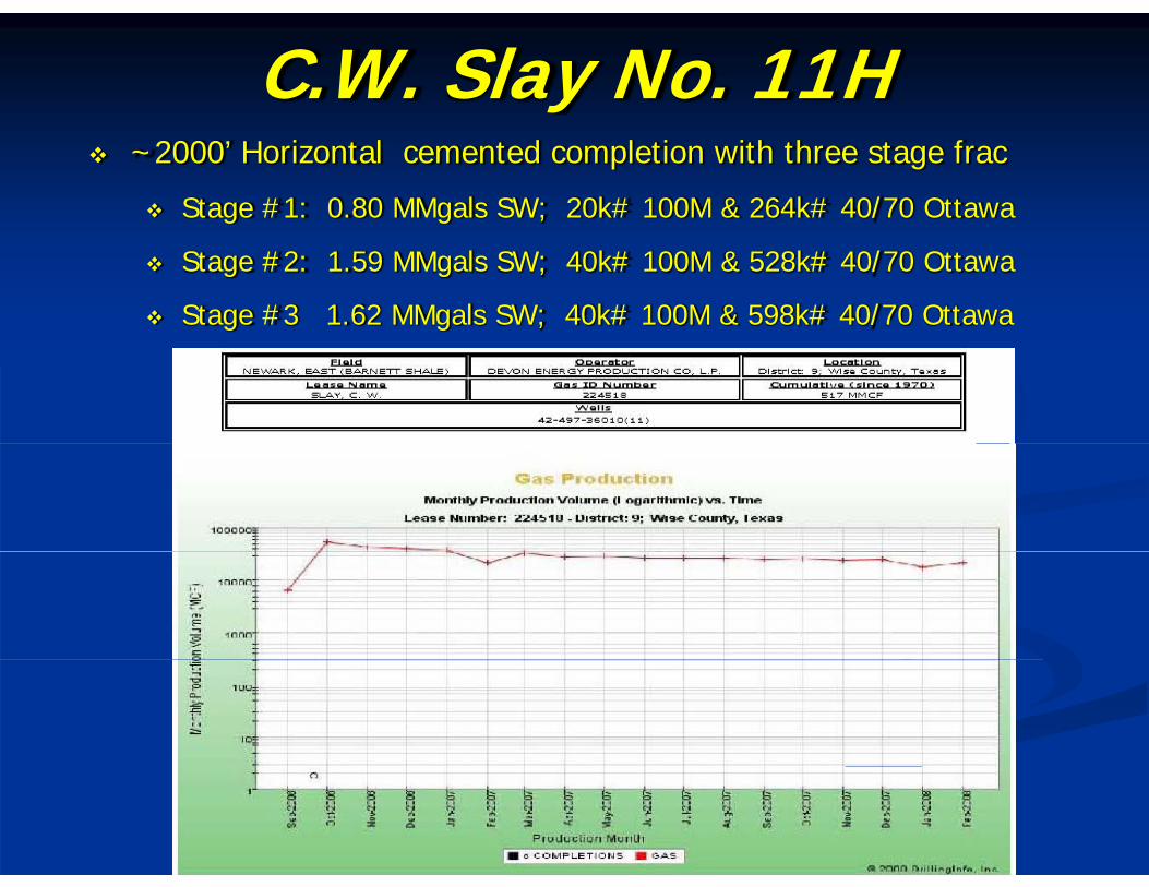
C.W. Slay No. 11H ~2000’ Horizontal cemented completion with three stage frac
Stage #1: 0.80 MMgals SW; 20k# 100M & 264k# 40/70 Ottawa
Stage #2: 1.59 MMgals SW; 40k# 100M & 528k# 40/70 Ottawa
Stage #3 1.62 MMgals SW; 40k# 100M & 598k# 40/70 Ottawa
Cornerstone N.G. Engineering, LP
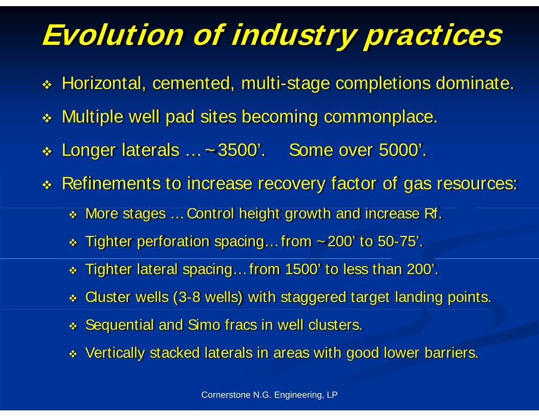
Evolution of industry practices Horizontal, cemented, multi-stage completions dominate.
Multiple well pad sites becoming commonplace.
Longer laterals … ~3500’. Some over 5000’.g
Refinements to increase recovery factor of gas resources:
M t C t l h i ht th d i Rf More stages … Control height growth and increase Rf.
Tighter perforation spacing… from ~200’ to 50-75’.
Tighter lateral spacing… from 1500’ to less than 200’.
Cluster wells (3-8 wells) with staggered target landing points.
Sequential and Simo fracs in well clusters.
Vertically stacked laterals in areas with good lower barriers.
Cornerstone N.G. Engineering, LP
y g
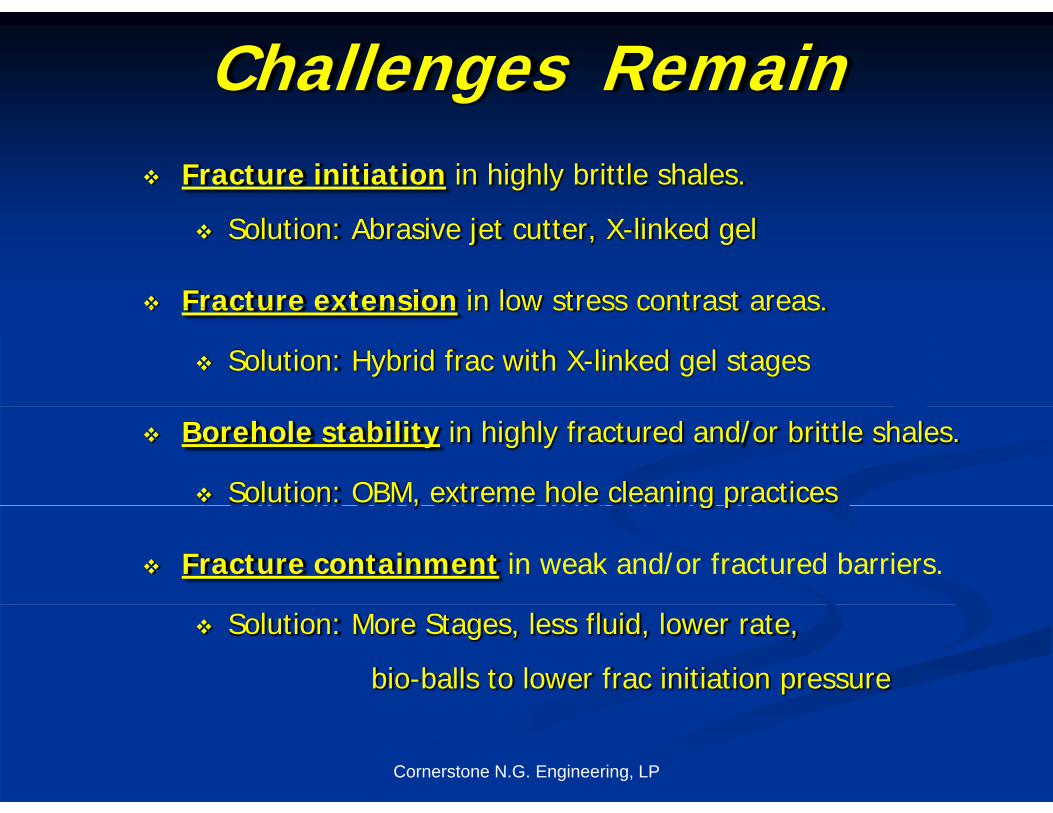
Challenges Remain Fracture initiation in highly brittle shales.
Solution: Abrasive jet cutter, X-linked gel
Fracture extension in low stress contrast areas. Fracture extension in low stress contrast areas.
Solution: Hybrid frac with X-linked gel stages
Borehole stability in highly fractured and/or brittle shales.
Solution: OBM, extreme hole cleaning practices, g p
Fracture containment in weak and/or fractured barriers.
Solution: More Stages, less fluid, lower rate,
bio-balls to lower frac initiation pressure
Cornerstone N.G. Engineering, LP

Thank you !
Cornerstone N.G. Engineering, LP