ndriveql hardwaremanual
TRANSCRIPT
J104
J105
High VoltageDANGER!
FIREWIRE
S1
DEVICE
NUMBER
ON
0
1
23
4
5
STAGE
J106
SYNC
J103
PWRENB/FLT
POWER INPUT
AC1
AC2
AUX I/O
J108
TB101
100-240V~
50/60Hz
2A MAX
ANALOG
I/O
J107
A B
Revision: 1.03.00
Ndrive QLHardware Manual

Global Technical SupportGo to www.aerotech.com/global-technical-support for information and support about your Aerotech products. The websiteprovides downloadable resources (such as up-to-date software, product manuals, and Help files), training schedules, andPC-to-PC remote technical support. You can also complete Product Return (RMA) forms and get information about repairsand spare or replacement parts. For immediate help, contact a service office or your sales representative. Have yourcustomer order number available before you call or include it in your email.
United States (World Headquarters)Phone: +1-412-967-6440Fax: +1-412-967-6870
Email: [email protected]
101 Zeta DrivePittsburgh, PA 15238-2811
www.aerotech.comUnited Kingdom Japan
Phone: +44 (0)1256 855055Fax: +44 (0)1256 855649
Email: [email protected]
Phone: +81 (0)50 5830 6814Fax: +81 (0)43 306 3773
Email: [email protected] China
Phone: +49 (0)911 967 9370Fax: +49 (0)911 967 93720
Email: [email protected]
Phone: +86 (21) 3319 7715Email: [email protected]
France TaiwanPhone: +33 2 37 21 87 65
Email: [email protected]: +886 (0)2 8751 6690Email: [email protected]
This manual contains proprietary information andmay not be reproduced, disclosed, or used in whole or in part without theexpress written permission of Aerotech, Inc. Product names mentioned herein are used for identification purposes only andmay be trademarks of their respective companies.
Copyright © 2015-2018, Aerotech, Inc., All rights reserved.
Ndrive QLHardwareManual Table of Contents
Table of Contents
Ndrive QL Hardware Manual 1Table of Contents 3List of Figures 4List of Tables 5EU Declaration of Conformity 7Agency Approvals 8Safety Procedures andWarnings 9Quick Installation Guide 11
Chapter 1: Introduction 131.1. Electrical Specifications 161.2. Mechanical Design 171.3. Environmental Specifications 18
Chapter 2: Installation and Configuration 192.1. Unpacking the Chassis 192.2. Electrical Installation 20
2.2.1. Power Input (TB101) 202.2.2. I/O and Signal Wiring Requirements 212.2.3. Communication Channel Settings 22
2.3. Stage Power and Feedback Connections (J106) 232.4. Auxiliary I/O Connector (J108) 25
2.4.1. Position Synchronized Output (PSO) 262.4.2. Opto-Isolated Outputs 0-3 282.4.3. Opto-Isolated Inputs 0-3 302.4.4. High-Speed User Inputs 4-5 322.4.5. Analog Output 0 332.4.6. Differential Analog Input 0 34
2.5. Analog I/O Connector (J107) 352.5.1. VoltageMonitor Output 362.5.2. External Voltage Command 37
2.6. Communication 382.6.1. FireWire Interface 382.6.2. SYNC Interface 40
2.7. PC Configuration andOperation Information 41
Chapter 3: Maintenance 433.1. PreventativeMaintenance 44
Appendix A: Warranty and Field Service 45Appendix B: Revision History 47Index 49
www.aerotech.com 3
Table of Contents Ndrive QLHardwareManual
List of Figures
Figure 1-1: Functional Diagram 15Figure 1-2: Dimensions 17Figure 2-1: Power Input Connections 20Figure 2-2: Connection to Third Party Stage 24Figure 2-3: PSO Interface 27Figure 2-4: Outputs Connected in Current SourcingMode (J108) 29Figure 2-5: Outputs Connected in Current SinkingMode (J108) 29Figure 2-6: Inputs Connected in Current SourcingMode (J108) 31Figure 2-7: Inputs Connected in Current SinkingMode (J108) 31Figure 2-8: High Speed User Inputs (J108) 32Figure 2-9: Analog Input 0 (J108) 34Figure 2-10: FireWire Interface 38Figure 2-11: Sync Interface 40
4 www.aerotech.com

Ndrive QLHardwareManual Table of Contents
List of Tables
Table 1-1: Configuration andOptions 14Table 1-2: Electrical Specifications 16Table 1-3: Physical Specifications 17Table 2-1: Power Supply Wiring (TB101) 20Table 2-2: I/O and Signal Wiring Specifications 21Table 2-3: Device Number Switch Settings (S1) 22Table 2-4: Power and Feedback Connector (J106) 23Table 2-5: Auxiliary I/O Interface Pin Assignment (J108) 25Table 2-6: PSOSpecifications 26Table 2-7: PSO Output Pin Assignment (J108) 26Table 2-8: Digital Output Specifications 28Table 2-9: Digital Output Connector Pin Assignment (J108) 28Table 2-10: PS2815-4 Opto-Device Specifications 30Table 2-11: Digital Input Connector Pin Assignment (J108) 30Table 2-12: High Speed Digital Input Connector Pin Assignment (J108) 32Table 2-13: High-Speed Digital Input Specifications 32Table 2-14: Analog Output Specifications (J108) 33Table 2-15: Analog Output 0 Connector Pin Assignment (J108) 33Table 2-16: Differential Analog Input Specifications (J108) 34Table 2-17: Analog Input Connector Pin Assignment (J108) 34Table 2-18: Analog I/O Connector Pin Assignment (J107) 35Table 2-19: VoltageMonitor Output Connector Pin Assignment (J107) 36Table 2-20: VoltageMonitor Output Scaling 36Table 2-21: VoltageMonitor Output Specifications 36Table 2-22: External Voltage CommandConnector Pin Assignment (J107) 37Table 2-23: External Voltage Command Scaling 37Table 2-24: External Voltage Command Specifications 37Table 2-25: FireWire Card Part Numbers 38Table 2-26: FireWire Repeaters (for cables exceeding 4.5m (15 ft) specification) 38Table 2-27: FireWire Cables (copper and glass fiber) 39Table 3-1: LED Description 43Table 3-2: Troubleshooting 43Table 3-3: PreventativeMaintenance 44
www.aerotech.com 5
Table of Contents Ndrive QLHardwareManual
6 www.aerotech.com
This page intentionally left blank.
Ndrive QLHardwareManual Declaration of Conformity
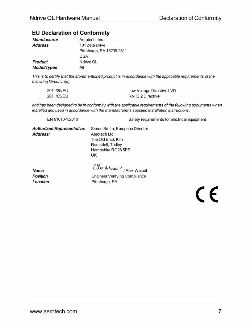
EU Declaration of ConformityManufacturer Aerotech, Inc.Address 101 Zeta Drive
Pittsburgh, PA 15238-2811USA
Product Ndrive QLModel/Types All
This is to certify that the aforementioned product is in accordance with the applicable requirements of thefollowing Directive(s):
2014/35/EU Low Voltage Directive LVD2011/65/EU RoHS 2 Directive
and has been designed to be in conformity with the applicable requirements of the following documents wheninstalled and used in accordance with themanufacturer’s supplied installation instructions.
EN 61010-1:2010 Safety requirements for electrical equipment
Authorized Representative: Simon Smith, European DirectorAddress: Aerotech Ltd
TheOld Brick KilnRamsdell, TadleyHampshire RG26 5PRUK
Name / Alex WeibelPosition Engineer Verifying ComplianceLocation Pittsburgh, PA
www.aerotech.com 7
Declaration of Conformity Ndrive QLHardwareManual
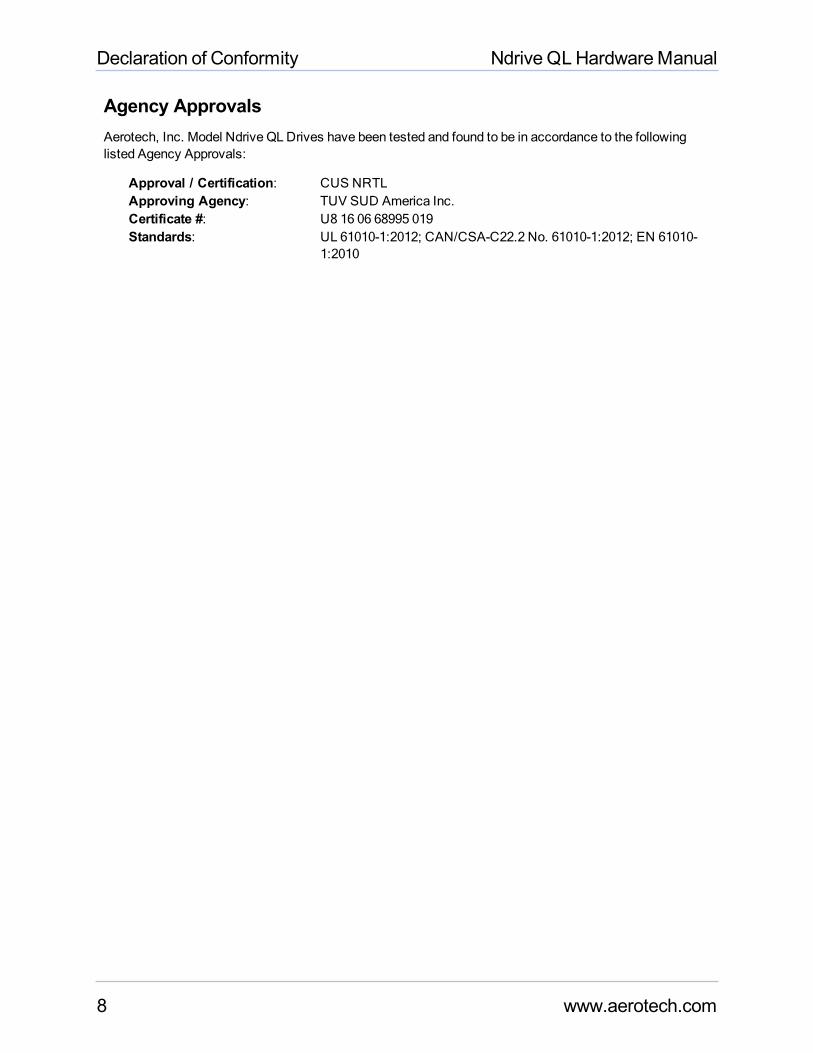
Agency ApprovalsAerotech, Inc. Model Ndrive QLDrives have been tested and found to be in accordance to the followinglisted Agency Approvals:
Approval / Certification: CUS NRTLApproving Agency: TUV SUD America Inc.Certificate #: U8 16 06 68995 019Standards: UL 61010-1:2012; CAN/CSA-C22.2 No. 61010-1:2012; EN 61010-
1:2010
8 www.aerotech.com
Ndrive QLHardwareManual Declaration of Conformity
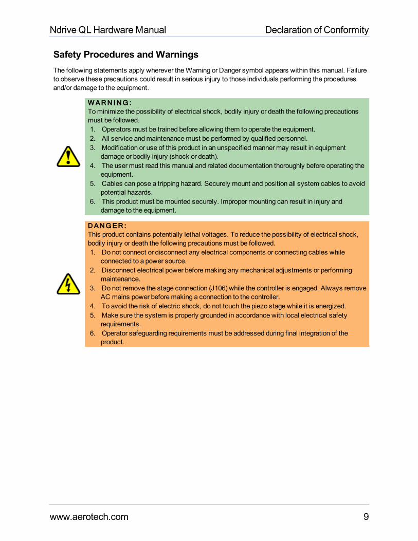
Safety Procedures and WarningsThe following statements apply wherever theWarning or Danger symbol appears within this manual. Failureto observe these precautions could result in serious injury to those individuals performing the proceduresand/or damage to the equipment.
WARN ING :Tominimize the possibility of electrical shock, bodily injury or death the following precautionsmust be followed.1. Operators must be trained before allowing them to operate the equipment.2. All service andmaintenancemust be performed by qualified personnel.3. Modification or use of this product in an unspecifiedmanner may result in equipment
damage or bodily injury (shock or death).4. The user must read this manual and related documentation thoroughly before operating the
equipment.5. Cables can pose a tripping hazard. Securely mount and position all system cables to avoid
potential hazards.6. This product must bemounted securely. Improper mounting can result in injury and
damage to the equipment.
DANGER :This product contains potentially lethal voltages. To reduce the possibility of electrical shock,bodily injury or death the following precautions must be followed.1. Do not connect or disconnect any electrical components or connecting cables while
connected to a power source.2. Disconnect electrical power beforemaking any mechanical adjustments or performing
maintenance.3. Do not remove the stage connection (J106) while the controller is engaged. Always remove
AC mains power beforemaking a connection to the controller.4. To avoid the risk of electric shock, do not touch the piezo stage while it is energized.5. Make sure the system is properly grounded in accordance with local electrical safety
requirements.6. Operator safeguarding requirements must be addressed during final integration of the
product.
www.aerotech.com 9
Declaration of Conformity Ndrive QLHardwareManual
10 www.aerotech.com
This page intentionally left blank.
Ndrive QLHardwareManual Quick Installation Guide
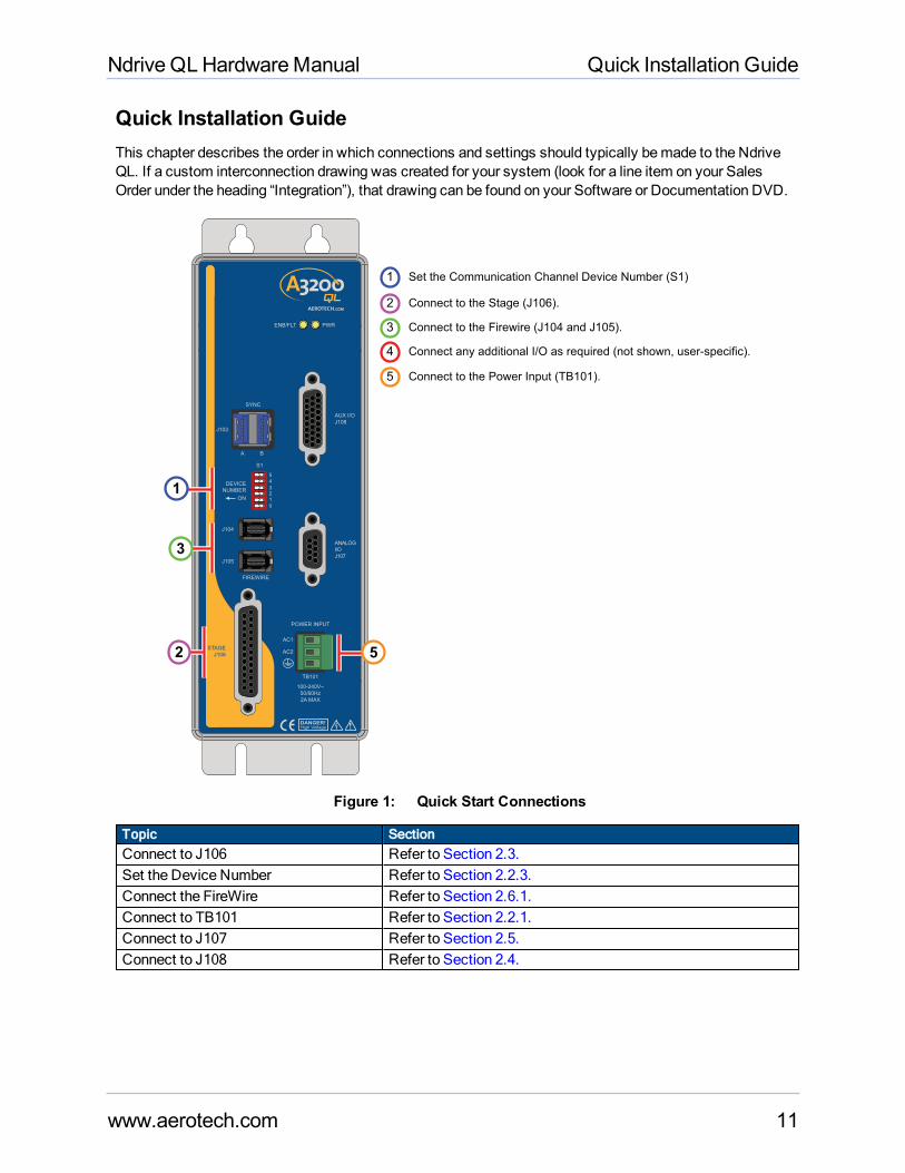
Quick Installation GuideThis chapter describes the order in which connections and settings should typically bemade to the NdriveQL. If a custom interconnection drawing was created for your system (look for a line item on your SalesOrder under the heading “Integration”), that drawing can be found on your Software or Documentation DVD.
J104
J105
High VoltageDANGER!
FIREWIRE
S1
DEVICE
NUMBER
ON
0
1
23
4
5
STAGE
J106
SYNC
J103
PWRENB/FLT
POWER INPUT
AC1
AC2
AUX I/O
J108
TB101
100-240V~
50/60Hz
2A MAX
ANALOG
I/O
J107
A B
2
3
1
5
Set the Communication Channel Device Number (S1)
Connect to the Firewire (J104 and J105).
Connect any additional I/O as required (not shown, user-specific).
Connect to the Power Input (TB101).
1
3
Connect to the Stage (J106).2
4
5
Figure 1: Quick Start Connections
Topic SectionConnect to J106 Refer to Section 2.3.Set the Device Number Refer to Section 2.2.3.Connect the FireWire Refer to Section 2.6.1.Connect to TB101 Refer to Section 2.2.1.Connect to J107 Refer to Section 2.5.Connect to J108 Refer to Section 2.4.
www.aerotech.com 11
Quick Installation Guide Ndrive QLHardwareManual
12 www.aerotech.com
This page intentionally left blank.
Ndrive QLHardwareManual Introduction
Chapter 1: IntroductionThe Ndrive QL is a panel-mount nanopositioning piezo drive that connects to any A3200 controller networkenabling a high rate of coordinatedmotion between piezo stages and servo axes.
QL drives feature a dual-core 456MHz, double-precision, floating-point DSP that provides extremeprocessing power over a wide variety of applications including point-to-point motion, linear and circularinterpolation, multi-axis error correction, and auto-focusing. High-speed interrupts and data loggingcapabilities provide a real-time link to external systems. TheQL also offers high-speed positioning latchingcapability and single-axis position synchronized output (PSO) for generation of pulses based on actualposition feedback in applications ranging from laser firing to data acquisition system triggering.
A
ENB/FLT (Enable/Fault) Indicator
PWR (Power) Indicator
J104
J105
High VoltageDANGER!
FIREWIRE
S1
DEVICE
NUMBER
ON
0
1
23
4
5
STAGE
J106
SYNC
J103
PWRENB/FLT
POWER INPUT
AC1
AC2
AUX I/O
J108
TB101
100-240V~
50/60Hz
2A MAX
ANALOG
I/O
J107
A B
A
E
G
F
B
C
DH
B AUX I/O (J108) Connector
C ANALOG I/O (J107) Connector
D POWER INPUT (TB101)
E SYNC (J103)
F DEVICE NUMBER (S1)
G FIREWIRE (J104, J105)
H STAGE (J106) Connector
www.aerotech.com Chapter 1 13
Introduction Ndrive QLHardwareManual
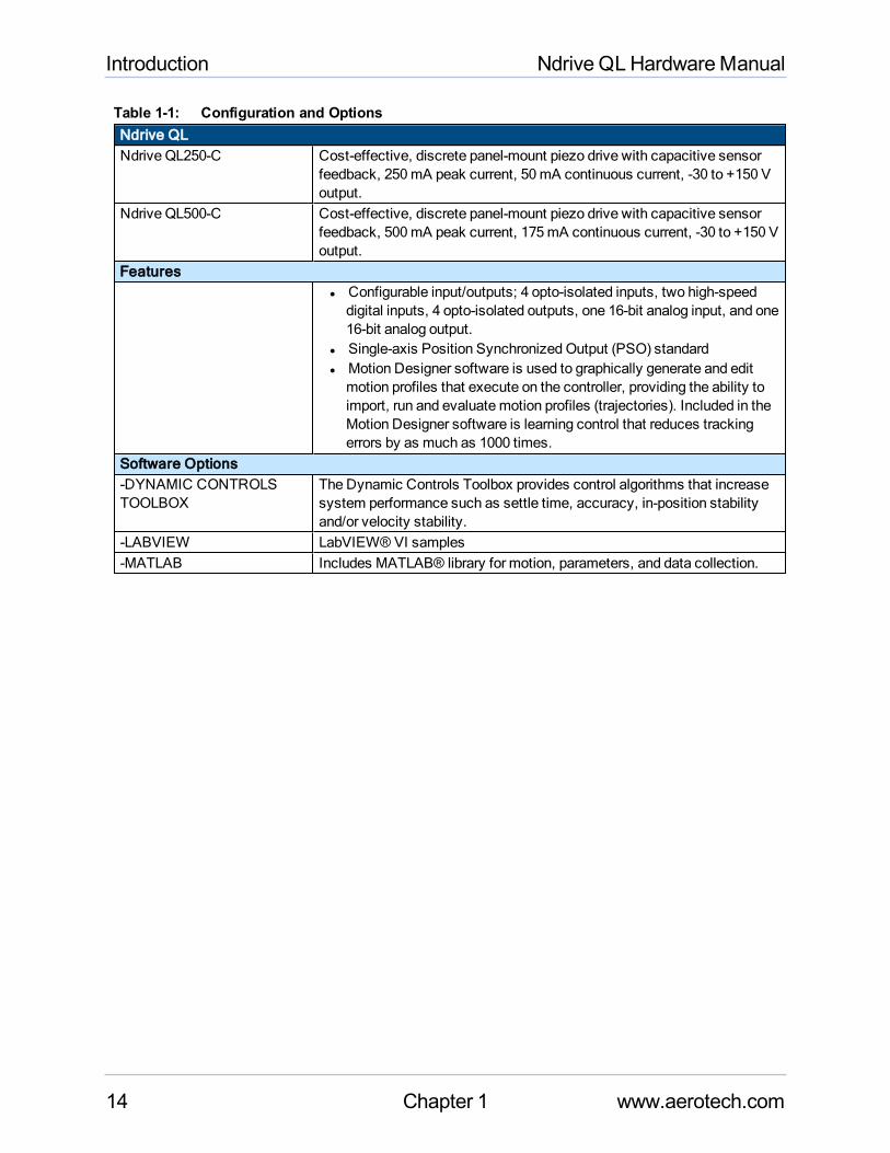
Table 1-1: Configuration and OptionsNdrive QLNdrive QL250-C Cost-effective, discrete panel-mount piezo drive with capacitive sensor
feedback, 250mA peak current, 50mA continuous current, -30 to +150 Voutput.
Ndrive QL500-C Cost-effective, discrete panel-mount piezo drive with capacitive sensorfeedback, 500mA peak current, 175mA continuous current, -30 to +150 Voutput.
Featuresl Configurable input/outputs; 4 opto-isolated inputs, two high-speeddigital inputs, 4 opto-isolated outputs, one 16-bit analog input, and one16-bit analog output.
l Single-axis Position Synchronized Output (PSO) standardl Motion Designer software is used to graphically generate and editmotion profiles that execute on the controller, providing the ability toimport, run and evaluatemotion profiles (trajectories). Included in theMotion Designer software is learning control that reduces trackingerrors by as much as 1000 times.
Software Options-DYNAMIC CONTROLSTOOLBOX
TheDynamic Controls Toolbox provides control algorithms that increasesystem performance such as settle time, accuracy, in-position stabilityand/or velocity stability.
-LABVIEW LabVIEW® VI samples-MATLAB Includes MATLAB® library for motion, parameters, and data collection.
14 Chapter 1 www.aerotech.com
Ndrive QLHardwareManual Introduction
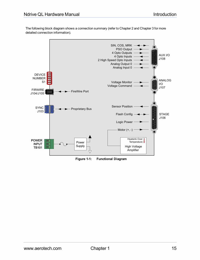
The following block diagram shows a connection summary (refer to Chapter 2 and Chapter 3 for moredetailed connection information).
STAGE
J106
Motor (+, -)
Logic Power
Sensor Position
Flash Config
Power
Supply High Voltage
Amplifier
Heatsink Over
Temperature
AUX I/O
J108
Analog Input 0
Analog Output 0
2 High Speed Opto Inputs
4 Opto Inputs
4 Opto Outputs
PSO Output
SIN, COS, MRK
SYNC
J103Proprietary Bus
ANALOG
I/O
J107Voltage Command
Voltage Monitor
POWER
INPUT
TB101
POWER
INPUT
TB101
DEVICE
NUMBER
S1
FIRWIRE
J104/J105FireWire Port
Figure 1-1: Functional Diagram
www.aerotech.com Chapter 1 15
Introduction Ndrive QLHardwareManual
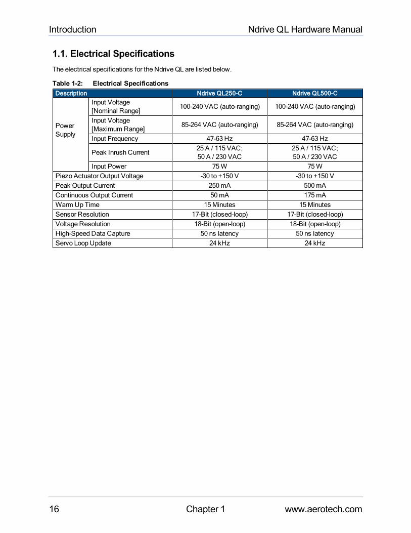
1.1. Electrical SpecificationsThe electrical specifications for the Ndrive QL are listed below.
Table 1-2: Electrical SpecificationsDescription Ndrive QL250-C Ndrive QL500-C
PowerSupply
Input Voltage[Nominal Range]
100-240 VAC (auto-ranging) 100-240 VAC (auto-ranging)
Input Voltage[Maximum Range]
85-264 VAC (auto-ranging) 85-264 VAC (auto-ranging)
Input Frequency 47-63 Hz 47-63 Hz
Peak Inrush Current25 A / 115 VAC;50 A / 230 VAC
25 A / 115 VAC;50 A / 230 VAC
Input Power 75W 75WPiezo Actuator Output Voltage -30 to +150 V -30 to +150 VPeak Output Current 250mA 500mAContinuous Output Current 50mA 175mAWarm Up Time 15Minutes 15MinutesSensor Resolution 17-Bit (closed-loop) 17-Bit (closed-loop)Voltage Resolution 18-Bit (open-loop) 18-Bit (open-loop)High-Speed Data Capture 50 ns latency 50 ns latencyServo Loop Update 24 kHz 24 kHz
16 Chapter 1 www.aerotech.com
Ndrive QLHardwareManual Introduction
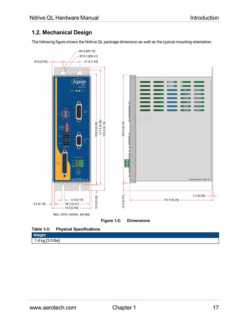
1.2. Mechanical DesignThe following figure shows the Ndrive QL package dimension as well as the typical mounting orientation.
Drawing Number: 620E1421-
J104
J105
High VoltageDANGER!
FIREWIRE
S1
DEVICE
NUMBER
ON
0
1
23
4
5
STAGE
J106
SYNC
J103
PWRENB/FLT
POWER INPUT
AC1
AC2
AUX I/O
J108
TB101
100-240V~
50/60Hz
2A MAX
ANALOG
I/O
J107
A B
157.5 [6.20]
Ø4.8 [Ø0.19]
Ø10.3 [Ø0.41]
31.8 [1.25]20.8 [0.82]
4.5 [0.18]
4.8 [0.19]
66.3 [2.61]
73.8 [2.90]
REC. MTG. HDWR.: M4 [#8]
2.3 [0.09]
14
.5 [0
.57
]
10
.9 [0
.43
]
20
3.8
[8
.02
]
21
7.4
[8
.56
]
20
9.8
[8
.26
]
23
3.0
[9
.16
]
Figure 1-2: Dimensions
Table 1-3: Physical SpecificationsWeight1.4 kg [3.0 lbs]
www.aerotech.com Chapter 1 17
Introduction Ndrive QLHardwareManual
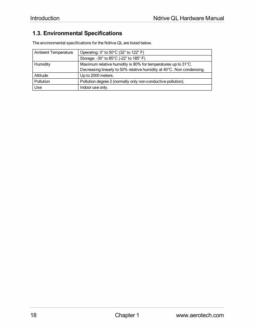
1.3. Environmental SpecificationsThe environmental specifications for the Ndrive QL are listed below.
Ambient Temperature Operating: 0° to 50°C (32° to 122° F)Storage: -30° to 85°C (-22° to 185° F)
Humidity Maximum relative humidity is 80% for temperatures up to 31°C.Decreasing linearly to 50% relative humidity at 40°C. Non condensing.
Altitude Up to 2000meters.Pollution Pollution degree 2 (normally only non-conductive pollution).Use Indoor use only.
18 Chapter 1 www.aerotech.com
Ndrive QLHardwareManual Installation and Configuration
Chapter 2: Installation and ConfigurationThis section describes theminimum hardware installation and configuration requirements for the Ndrive QL.This installation will provide information on AC power connections andmotor wiring.
DANGER : Tominimize the possibility of bodily injury or death, disconnect all electricalpower prior to performing any maintenance or making adjustments to the equipment.
2.1. Unpacking the ChassisDANGER : All electronic equipment and instrumentation are wrapped in antistatic materialand packaged with desiccant. Ensure that the antistatic material is not damaged duringunpacking.
Visually inspect the container of the QL for any evidence of shipping damage. If any such damage exists,notify the shipping carrier immediately.
Remove the packing list from theQL container. Make sure that all the items specified on the packing list arecontained within the package.
All of the documentation provided with the QL should be saved for future reference. Additional informationabout the QL system is provided on the Serial and Power labels that are placed on theQL chassis.
The system serial number label contains important information such as the:
l Customer order number (please provide this number when requesting product support)l Drawing numberl System part number
www.aerotech.com Chapter 2 19
Installation and Configuration Ndrive QLHardwareManual
2.2. Electrical InstallationThe Ndrive QL has one AC input power connector. For a complete list of electrical specifications, refer toSection 1.1. Electrical Specifications.
2.2.1. Power Input (TB101)AC input power to the QL is applied to the Input Power (TB101) connector.
The connection requires aminimum of 100 VAC input to operate properly. The AC1 and AC2 inputs areinternally fused. Figure 2-1 shows the required connections to the control power input.
POWER INPUT
AC1
AC2
TB101
100-240V~
50/60Hz
2A MAX
Figure 2-1: Power Input Connections
Table 2-1: Power Supply Wiring (TB101)Pin Description Recommended Wire Size
AC1 100 - 240 VAC Input Range 1.3mm2 (#16 AWG)
AC2 100 - 240 VAC Input Range 1.3mm2 (#16 AWG)
Protective Ground (Required for Safety) 1.3mm2 (#16 AWG)
Type Aerotech P/N Phoenix P/NScrew TorqueValue: Nm
Wire Size:AWG [mm2]
3-Pin Terminal Block ECK00213 1754465 0.5 - 0.6 12-30 [3.3 - 0.516]
20 Chapter 2 www.aerotech.com
Ndrive QLHardwareManual Installation and Configuration
2.2.2. I/O and Signal Wiring RequirementsThe I/O, communication, and encoder feedback connections are typically very low power connections. Insome applications, especially when there are significant wire distances, a larger wire sizemay be required toreduce the voltage drop that occurs along the wire. This increasemay be necessary in order to keep thevoltage within a specified range at a remote point.
Low voltage and high voltage wires should be kept physically separated so that they cannot contact oneanother. This reduces the risk of electric shock and improves system performance.
Table 2-2: I/O and Signal Wiring SpecificationsConnection Specification Value
Signal WiringCable/Wire Rating (1) 300 VMinimum Current Capacity .25 ATemperature Rating (Insulation) (2) 80°C
Low Voltage PowerCable/Wire Rating (1) 300 VMinimum Current Capacity (3) 1 ATemperature Rating (Insulation) (2) 80°C
1. ≥ 30 V if the wiring isnot in close proximity to wiring operating at voltagesabove 60 V.2. Insulation rating will need to be rated for the higher voltage if the wiring is in proximity to wiring operating at voltagesabove 60 V.3. Larger gauge wiremaybe required tominimize voltage drop due to voltage (IR) loss in the cable.
www.aerotech.com Chapter 2 21
Installation and Configuration Ndrive QLHardwareManual
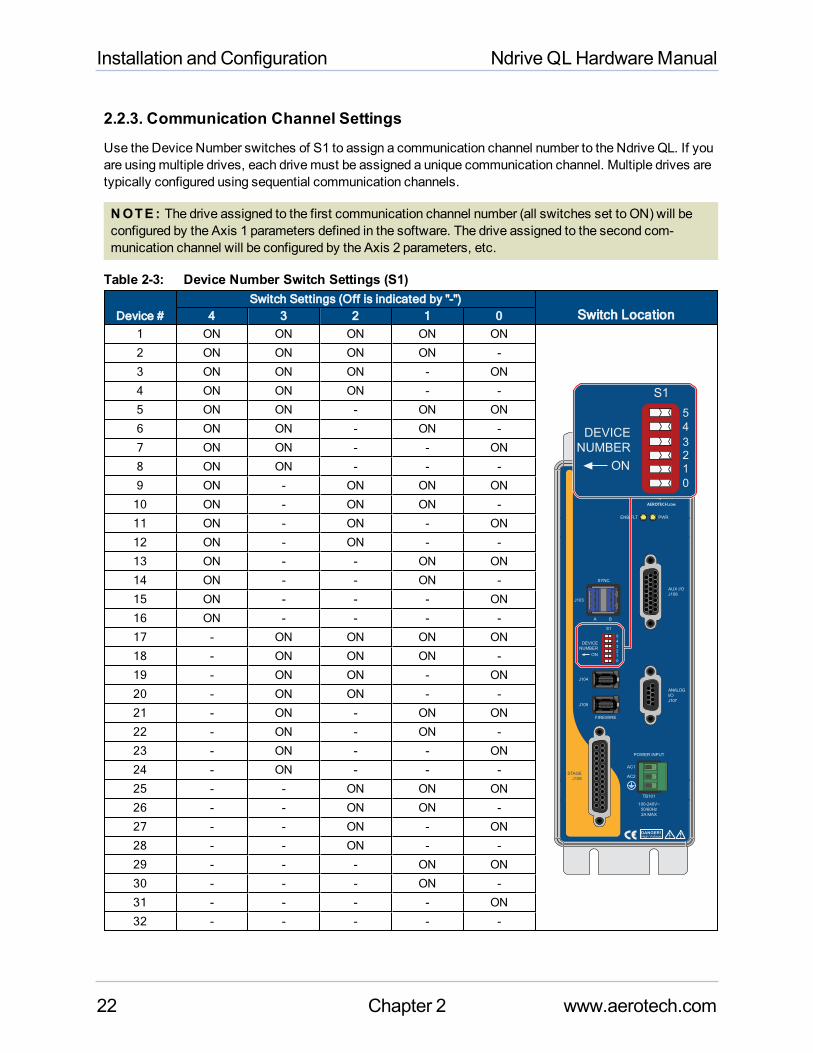
2.2.3. Communication Channel SettingsUse the Device Number switches of S1 to assign a communication channel number to the Ndrive QL. If youare usingmultiple drives, each drivemust be assigned a unique communication channel. Multiple drives aretypically configured using sequential communication channels.
NOTE : The drive assigned to the first communication channel number (all switches set to ON) will beconfigured by the Axis 1 parameters defined in the software. The drive assigned to the second com-munication channel will be configured by the Axis 2 parameters, etc.
Table 2-3: Device Number Switch Settings (S1)
Device #Switch Settings (Off is indicated by "-")
Switch Location4 3 2 1 01 ON ON ON ON ON
J104
J105
High VoltageDANGER!
FIREWIRE
S1
DEVICE
NUMBER
ON
0
1
23
4
5
STAGE
J106
SYNC
J103
PWRENB/FLT
POWER INPUT
AC1
AC2
AUX I/O
J108
TB101
100-240V~
50/60Hz
2A MAX
ANALOG
I/O
J107
A B
S1
DEVICE
NUMBER
ON
0
1
23
4
5
2 ON ON ON ON -
3 ON ON ON - ON
4 ON ON ON - -
5 ON ON - ON ON
6 ON ON - ON -
7 ON ON - - ON
8 ON ON - - -
9 ON - ON ON ON
10 ON - ON ON -
11 ON - ON - ON
12 ON - ON - -
13 ON - - ON ON
14 ON - - ON -
15 ON - - - ON
16 ON - - - -
17 - ON ON ON ON
18 - ON ON ON -
19 - ON ON - ON
20 - ON ON - -
21 - ON - ON ON
22 - ON - ON -
23 - ON - - ON
24 - ON - - -
25 - - ON ON ON
26 - - ON ON -
27 - - ON - ON
28 - - ON - -
29 - - - ON ON
30 - - - ON -
31 - - - - ON
32 - - - - -
22 Chapter 2 www.aerotech.com
Ndrive QLHardwareManual Installation and Configuration
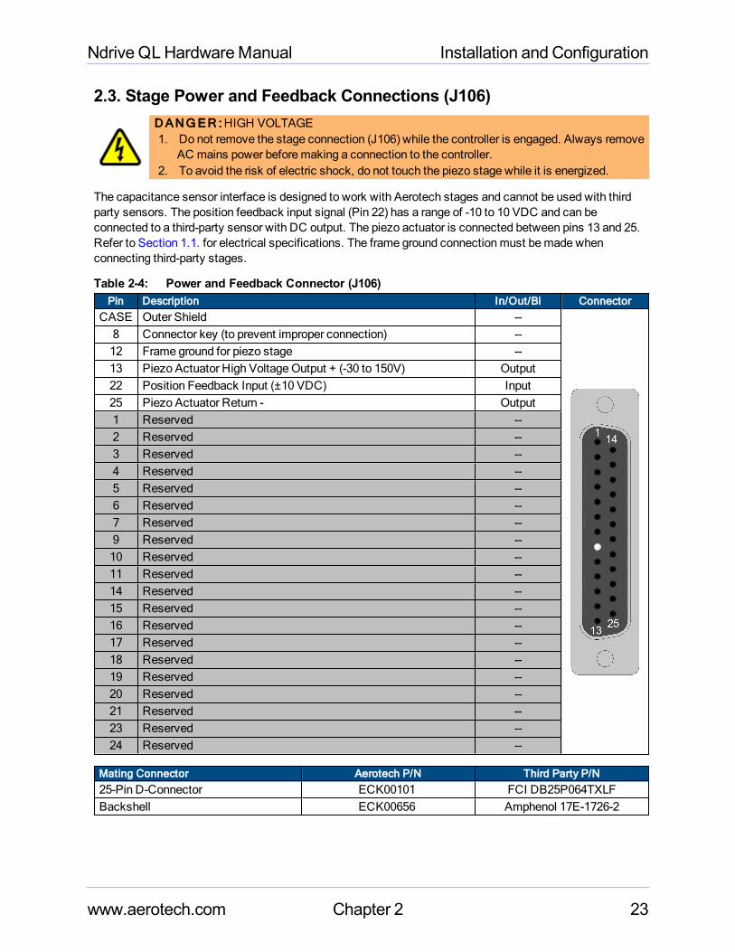
2.3. Stage Power and Feedback Connections (J106)DANGER :HIGH VOLTAGE1. Do not remove the stage connection (J106) while the controller is engaged. Always remove
AC mains power beforemaking a connection to the controller.2. To avoid the risk of electric shock, do not touch the piezo stage while it is energized.
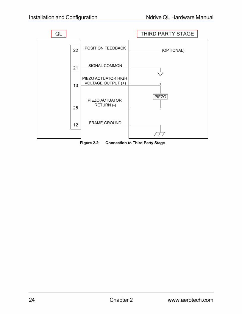
The capacitance sensor interface is designed to work with Aerotech stages and cannot be used with thirdparty sensors. The position feedback input signal (Pin 22) has a range of -10 to 10 VDC and can beconnected to a third-party sensor with DC output. The piezo actuator is connected between pins 13 and 25.Refer to Section 1.1. for electrical specifications. The frame ground connectionmust bemade whenconnecting third-party stages.
Table 2-4: Power and Feedback Connector (J106)Pin Description In/Out/Bi Connector
CASE Outer Shield --8 Connector key (to prevent improper connection) --12 Frame ground for piezo stage --13 Piezo Actuator High VoltageOutput + (-30 to 150V) Output22 Position Feedback Input (±10 VDC) Input25 Piezo Actuator Return - Output1 Reserved --2 Reserved --3 Reserved --4 Reserved --5 Reserved --6 Reserved --7 Reserved --9 Reserved --10 Reserved --11 Reserved --14 Reserved --15 Reserved --16 Reserved --17 Reserved --18 Reserved --19 Reserved --20 Reserved --21 Reserved --23 Reserved --24 Reserved --
Mating Connector Aerotech P/N Third Party P/N25-Pin D-Connector ECK00101 FCI DB25P064TXLFBackshell ECK00656 Amphenol 17E-1726-2
www.aerotech.com Chapter 2 23
Installation and Configuration Ndrive QLHardwareManual
THIRD PARTY STAGE
13
25
22
21
12
PIEZO
(OPTIONAL)POSITION FEEDBACK
SIGNAL COMMON
FRAME GROUND
PIEZO ACTUATOR HIGH
VOLTAGE OUTPUT (+)
PIEZO ACTUATOR
RETURN (-)
+
-
QL
Figure 2-2: Connection to Third Party Stage
24 Chapter 2 www.aerotech.com
Ndrive QLHardwareManual Installation and Configuration
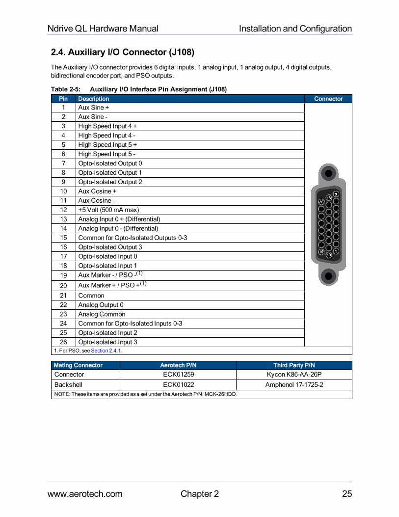
2.4. Auxiliary I/O Connector (J108)The Auxiliary I/O connector provides 6 digital inputs, 1 analog input, 1 analog output, 4 digital outputs,bidirectional encoder port, and PSO outputs.
Table 2-5: Auxiliary I/O Interface Pin Assignment (J108)Pin Description Connector1 Aux Sine +2 Aux Sine -3 High Speed Input 4 +4 High Speed Input 4 -5 High Speed Input 5 +6 High Speed Input 5 -7 Opto-Isolated Output 08 Opto-Isolated Output 19 Opto-Isolated Output 210 Aux Cosine +11 Aux Cosine -12 +5 Volt (500mA max)13 Analog Input 0 + (Differential)14 Analog Input 0 - (Differential)15 Common for Opto-Isolated Outputs 0-316 Opto-Isolated Output 317 Opto-Isolated Input 018 Opto-Isolated Input 119 Aux Marker - / PSO -(1)
20 Aux Marker + / PSO +(1)
21 Common22 Analog Output 023 Analog Common24 Common for Opto-Isolated Inputs 0-325 Opto-Isolated Input 226 Opto-Isolated Input 3
1. For PSO, see Section 2.4.1.
Mating Connector Aerotech P/N Third Party P/N
Connector ECK01259 Kycon K86-AA-26P
Backshell ECK01022 Amphenol 17-1725-2NOTE: These itemsare provided asa set under the Aerotech P/N: MCK-26HDD.
www.aerotech.com Chapter 2 25
Installation and Configuration Ndrive QLHardwareManual
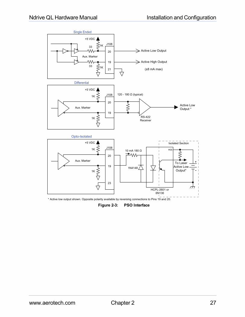
2.4.1. Position Synchronized Output (PSO)The PSO can be programmed to generate an output synchronized to the feedback position and is typicallyused to fire a laser or sequence an external device. Trigger signals may be derived from a feedback channelor a software trigger. The position synchronized output pulse is generated using high-speed hardware,allowingminimal latency between the trigger condition and the output.
The PSO output is available on the dual function AUX Marker/PSO signal lines as either a TTL or RS-422formatted signal (software configurable).
An RS-422 line receiver or opto-isolator is recommended, especially when using long cable lengths in noisyenvironments or when high frequency pulse transmission is required. It is best to locate the line receiver oropto-isolator close to the receiving electronics.
Table 2-6: PSO SpecificationsSpecification ValueMaximum Input Tracking Rate (1) Single-Axis Tracking 16.6MHzMaximumQuadrature Encoder OutputFrequency
Capacitance Sensor Feedback 16MHz
Maximum PSOOutput (Fire) Frequency (2) 12.5MHzFiring Latency Single-Axis Tracking 160 nsec1. Signals in excessof this rate will cause a lossof PSOaccuracy.2. The optocoupler that you use on the output might have an effect on this rate.
Table 2-7: PSO Output Pin Assignment (J108)Pin Description19 Aux Marker - / PSO -20 Aux Marker + / PSO +21 Common
26 Chapter 2 www.aerotech.com
Ndrive QLHardwareManual Installation and Configuration
J108
J108
+5 VDC
1K
1K
20
19
RS-422
Receiver
Active Low
Output *
* Active low output shown. Opposite polarity available by reversing connections to Pins 19 and 20.
Aux. Marker
120 - 180 Ω (typical)
10 mA 180 Ω
Differential
J108
+5 VDC
1K
1K33
33
20
19
Active Low Output
Active High Output
(±8 mA max)
Aux. Marker
Single Ended
+5 VDC Isolated Section
vcc
To Laser
Active Low
Output*
HCPL-2601 or
6N136
1N4148
1K
1K
20
19
23
21
Aux. Marker
Opto-Isolated
Figure 2-3: PSO Interface
www.aerotech.com Chapter 2 27
Installation and Configuration Ndrive QLHardwareManual
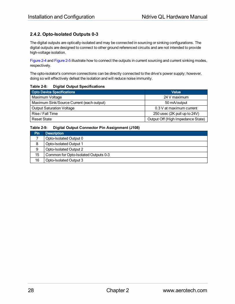
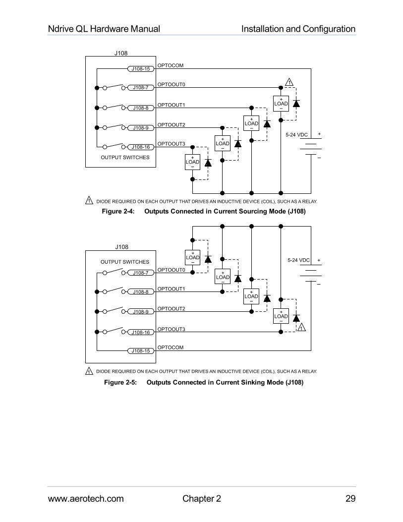
2.4.2. Opto-Isolated Outputs 0-3The digital outputs are optically-isolated andmay be connected in sourcing or sinking configurations. Thedigital outputs are designed to connect to other ground referenced circuits and are not intended to providehigh-voltage isolation.
Figure 2-4 and Figure 2-5 illustrate how to connect the outputs in current sourcing and current sinkingmodes,respectively.
The opto-isolator's common connections can be directly connected to the drive's power supply; however,doing so will effectively defeat the isolation and will reduce noise immunity.
Table 2-8: Digital Output SpecificationsOpto Device Specifications ValueMaximum Voltage 24 V maximumMaximum Sink/Source Current (each output) 50mA/outputOutput Saturation Voltage 0.3 V at maximum currentRise / Fall Time 250 usec (2K pull up to 24V)Reset State Output Off (High Impedance State)
Table 2-9: Digital Output Connector Pin Assignment (J108)Pin Description7 Opto-Isolated Output 08 Opto-Isolated Output 19 Opto-Isolated Output 215 Common for Opto-Isolated Outputs 0-316 Opto-Isolated Output 3
28 Chapter 2 www.aerotech.com
Ndrive QLHardwareManual Installation and Configuration
OPTOCOM
5-24 VDC
1
1
OUTPUT SWITCHES
J108
J108-15
J108-7
J108-8
J108-9
J108-16
DIODE REQUIRED ON EACH OUTPUT THAT DRIVES AN INDUCTIVE DEVICE (COIL), SUCH AS A RELAY.
+
-+LOAD-
+LOAD-
+LOAD-
+LOAD-
OPTOOUT0
OPTOOUT1
OPTOOUT2
OPTOOUT3
Figure 2-4: Outputs Connected in Current Sourcing Mode (J108)
OPTOCOM
5-24 VDC
1
1
OUTPUT SWITCHES
J108
J108-15
J108-7
J108-8
J108-9
J108-16
DIODE REQUIRED ON EACH OUTPUT THAT DRIVES AN INDUCTIVE DEVICE (COIL), SUCH AS A RELAY.
+
-
+LOAD-
+LOAD-
+LOAD-
+LOAD-
OPTOOUT0
OPTOOUT1
OPTOOUT2
OPTOOUT3
Figure 2-5: Outputs Connected in Current Sinking Mode (J108)
www.aerotech.com Chapter 2 29
Installation and Configuration Ndrive QLHardwareManual
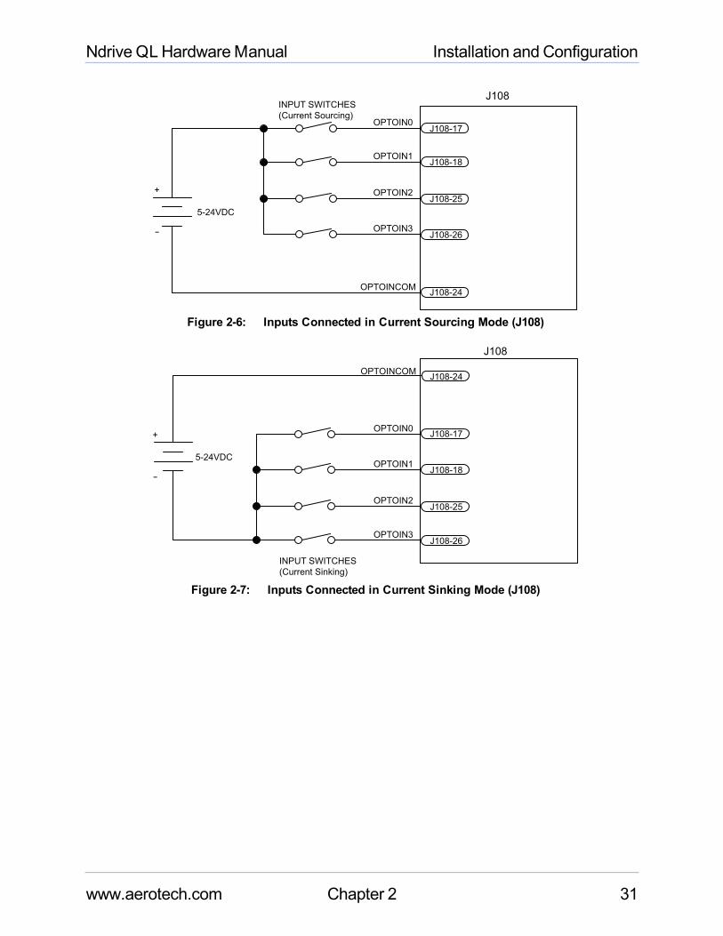
2.4.3. Opto-Isolated Inputs 0-3The digital inputs are opto-isolated andmay be connected to current sourcing or current sinking devices, asshown in Figure 2-6 and Figure 2-7. These inputs are designed to connect to other ground-referenced circuitsand are not intended for high-voltage isolation.
The opto-isolator's common connections can be directly connected to the drive's power supply; however,doing so will effectively defeat the isolation and will reduce noise immunity.
Table 2-10: PS2815-4 Opto-Device SpecificationsInput Voltage Approximate Input Current Turn On/Off Time5 to 24 V 5mA <100 usec
Table 2-11: Digital Input Connector Pin Assignment (J108)Pin Description17 Opto-Isolated Input 018 Opto-Isolated Input 124 Common for Opto-Isolated Inputs 0-325 Opto-Isolated Input 226 Opto-Isolated Input 3
30 Chapter 2 www.aerotech.com
Ndrive QLHardwareManual Installation and Configuration
INPUT SWITCHES
(Current Sourcing)
5-24VDC
OPTOINCOMJ108-24
J108-26
J108-25
J108-18
J108-17
+
-
J108
OPTOIN3
OPTOIN2
OPTOIN1
OPTOIN0
Figure 2-6: Inputs Connected in Current Sourcing Mode (J108)
INPUT SWITCHES
(Current Sinking)
5-24VDC
OPTOINCOMJ108-24
J108-26
J108-25
J108-18
J108-17+
-
J108
OPTOIN3
OPTOIN2
OPTOIN1
OPTOIN0
Figure 2-7: Inputs Connected in Current Sinking Mode (J108)
www.aerotech.com Chapter 2 31
Installation and Configuration Ndrive QLHardwareManual
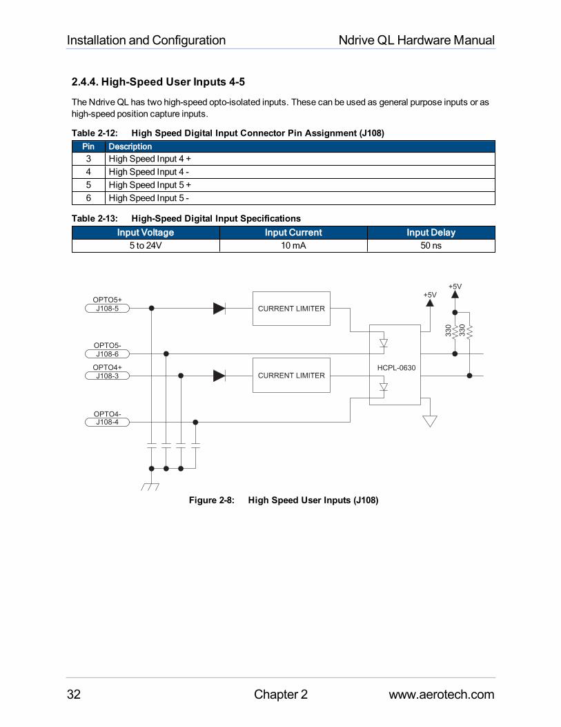
2.4.4. High-Speed User Inputs 4-5The Ndrive QL has two high-speed opto-isolated inputs. These can be used as general purpose inputs or ashigh-speed position capture inputs.
Table 2-12: High Speed Digital Input Connector Pin Assignment (J108)Pin Description3 High Speed Input 4 +4 High Speed Input 4 -5 High Speed Input 5 +6 High Speed Input 5 -
Table 2-13: High-Speed Digital Input SpecificationsInput Voltage Input Current Input Delay
5 to 24V 10mA 50 ns
J108-3
J108-4
J108-5
J108-6
HCPL-0630
330
330
CURRENT LIMITER
+5V
+5V
OPTO4+
OPTO4-
OPTO5+
OPTO5-
CURRENT LIMITER
Figure 2-8: High Speed User Inputs (J108)
32 Chapter 2 www.aerotech.com
Ndrive QLHardwareManual Installation and Configuration
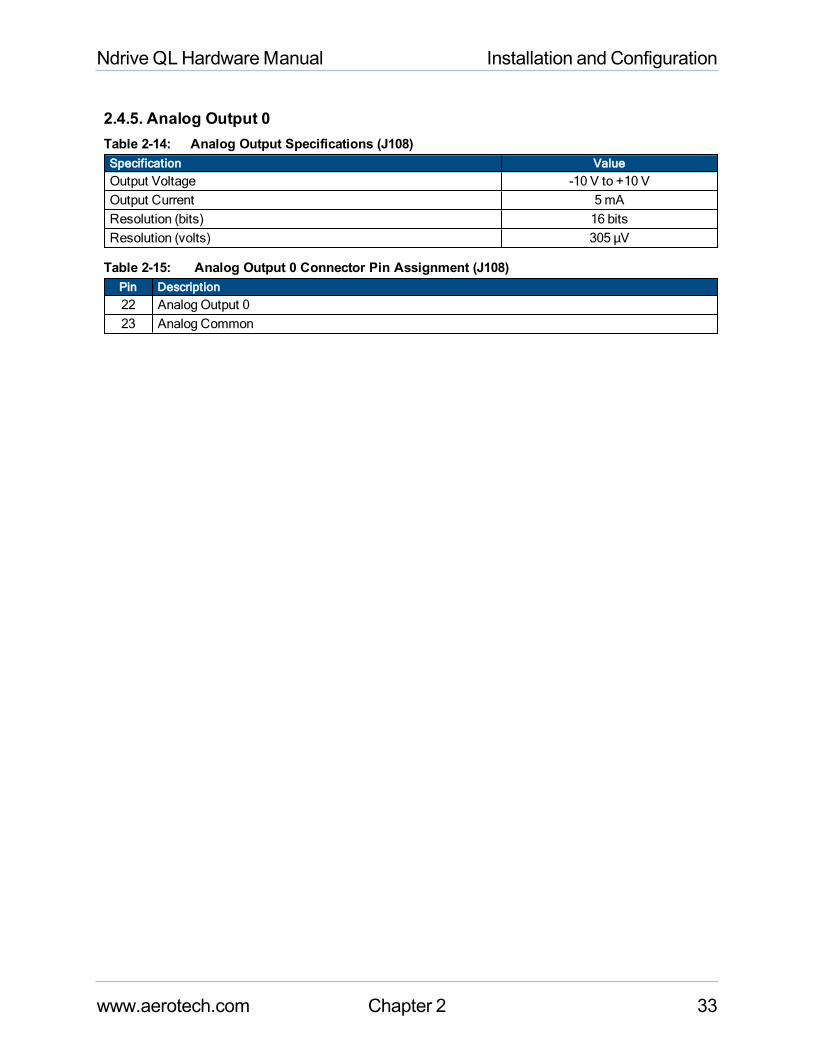
2.4.5. Analog Output 0Table 2-14: Analog Output Specifications (J108)Specification ValueOutput Voltage -10 V to +10 VOutput Current 5mAResolution (bits) 16 bitsResolution (volts) 305 µV
Table 2-15: Analog Output 0 Connector Pin Assignment (J108)Pin Description22 Analog Output 023 Analog Common
www.aerotech.com Chapter 2 33
Installation and Configuration Ndrive QLHardwareManual
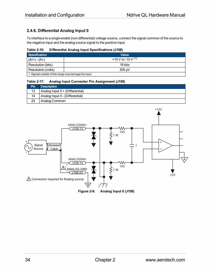
2.4.6. Differential Analog Input 0To interface to a single-ended (non-differential) voltage source, connect the signal common of the source tothe negative input and the analog source signal to the positive input.
Table 2-16: Differential Analog Input Specifications (J108)Specification Value
(AI+) - (AI-) +10 V to -10 V (1)
Resolution (bits) 16 bitsResolution (volts) 305 µV1. Signals outside of this rangemaydamage the input
Table 2-17: Analog Input Connector Pin Assignment (J108)Pin Description13 Analog Input 0 + (Differential)14 Analog Input 0 - (Differential)23 Analog Common
+
-.1
100
100
J108-14
J108-13
A
+12V
-12V
1 M
1 M
ANALOGIN0-
ANALOGIN0+
+
-
ANALOG GND
J108-23
Shielded
Cable
1
1 Connection required for floating source.
Signal
Source
A
Figure 2-9: Analog Input 0 (J108)
34 Chapter 2 www.aerotech.com
Ndrive QLHardwareManual Installation and Configuration
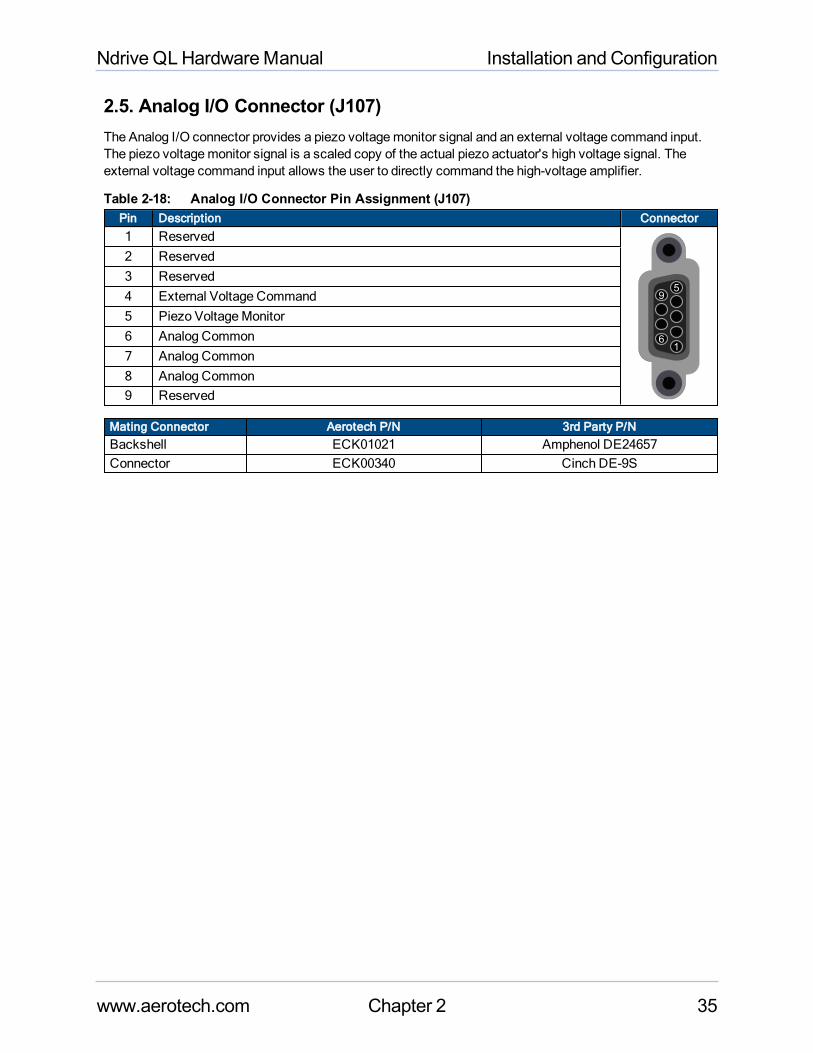
2.5. Analog I/O Connector (J107)The Analog I/O connector provides a piezo voltagemonitor signal and an external voltage command input.The piezo voltagemonitor signal is a scaled copy of the actual piezo actuator's high voltage signal. Theexternal voltage command input allows the user to directly command the high-voltage amplifier.
Table 2-18: Analog I/O Connector Pin Assignment (J107)Pin Description Connector1 Reserved
1
5
6
9
2 Reserved3 Reserved4 External Voltage Command5 Piezo VoltageMonitor6 Analog Common7 Analog Common8 Analog Common9 Reserved
Mating Connector Aerotech P/N 3rd Party P/NBackshell ECK01021 Amphenol DE24657Connector ECK00340 Cinch DE-9S
www.aerotech.com Chapter 2 35
Installation and Configuration Ndrive QLHardwareManual
2.5.1. Voltage Monitor OutputThe VoltageMonitor output provides a scaled copy of the piezo actuator's high-voltage signal. The high-voltage signal is scaled by 1/15 and buffered before being sent to the VoltageMonitor output pin.
Table 2-19: Voltage Monitor Output Connector Pin Assignment (J107)Pin Description5 Piezo VoltageMonitor8 Analog Common
Table 2-20: Voltage Monitor Output ScalingPiezo Voltage Voltage Monitor
+150 V +10 V0 V 0 V-30 V -2 V
Table 2-21: Voltage Monitor Output SpecificationsDescription
Accuracy ±3.5% NominalRecommended Load ≥10k Ω
36 Chapter 2 www.aerotech.com
Ndrive QLHardwareManual Installation and Configuration
2.5.2. External Voltage CommandThe External Voltage Command input allows the user to directly command the Ndrive QL's high voltageamplifier. This modemust be enabled using the controller software and is not active by default.
Table 2-22: External Voltage Command Connector Pin Assignment (J107)Pin Description4 External Voltage Command8 Analog Common
Table 2-23: External Voltage Command ScalingExternal Voltage Command (Input) Piezo Voltage (Output)
+10 V +150 V0 V 0 V-2 V -30 V
Table 2-24: External Voltage Command SpecificationsDescription
Input Range -2V to +10VInput Impedance 20k Ω
www.aerotech.com Chapter 2 37
Installation and Configuration Ndrive QLHardwareManual
2.6. Communication
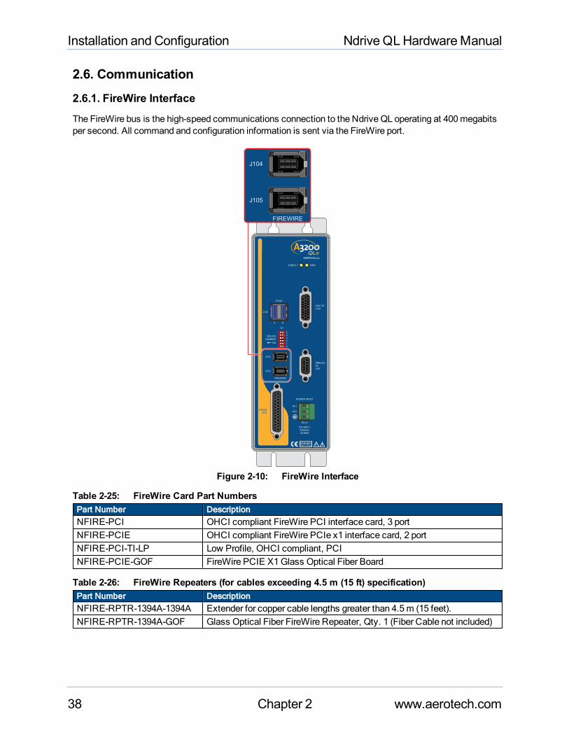
2.6.1. FireWire InterfaceThe FireWire bus is the high-speed communications connection to the Ndrive QL operating at 400megabitsper second. All command and configuration information is sent via the FireWire port.
J104
J105
High VoltageDANGER!
FIREWIRE
S1
DEVICE
NUMBER
ON
0
1
23
4
5
STAGE
J106
SYNC
J103
PWRENB/FLT
POWER INPUT
AC1
AC2
AUX I/O
J108
TB101
100-240V~
50/60Hz
2A MAX
ANALOG
I/O
J107
A B
J104
J105
FIREWIRE
Figure 2-10: FireWire Interface
Table 2-25: FireWire Card Part NumbersPart Number DescriptionNFIRE-PCI OHCI compliant FireWire PCI interface card, 3 portNFIRE-PCIE OHCI compliant FireWire PCIe x1 interface card, 2 portNFIRE-PCI-TI-LP Low Profile, OHCI compliant, PCINFIRE-PCIE-GOF FireWire PCIE X1Glass Optical Fiber Board
Table 2-26: FireWire Repeaters (for cables exceeding 4.5 m (15 ft) specification)Part Number DescriptionNFIRE-RPTR-1394A-1394A Extender for copper cable lengths greater than 4.5m (15 feet).NFIRE-RPTR-1394A-GOF Glass Optical Fiber FireWire Repeater, Qty. 1 (Fiber Cable not included)
38 Chapter 2 www.aerotech.com
Ndrive QLHardwareManual Installation and Configuration
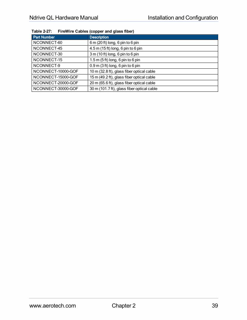
Table 2-27: FireWire Cables (copper and glass fiber) Part Number DescriptionNCONNECT-60 6m (20 ft) long, 6 pin to 6 pinNCONNECT-45 4.5m (15 ft) long, 6 pin to 6 pinNCONNECT-30 3m (10 ft) long, 6 pin to 6 pinNCONNECT-15 1.5m (5 ft) long, 6 pin to 6 pinNCONNECT-9 0.9m (3 ft) long, 6 pin to 6 pinNCONNECT-10000-GOF 10m (32.8 ft), glass fiber optical cableNCONNECT-15000-GOF 15m (49.2 ft), glass fiber optical cableNCONNECT-20000-GOF 20m (65.6 ft), glass fiber optical cableNCONNECT-30000-GOF 30m (101.7 ft), glass fiber optical cable
www.aerotech.com Chapter 2 39
Installation and Configuration Ndrive QLHardwareManual
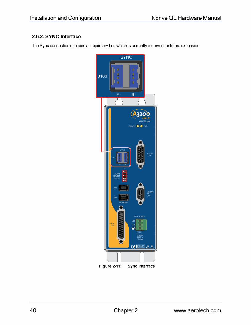
2.6.2. SYNC InterfaceThe Sync connection contains a proprietary bus which is currently reserved for future expansion.
J104
J105
High VoltageDANGER!
FIREWIRE
S1
DEVICE
NUMBER
ON
0
1
23
4
5
STAGE
J106
SYNC
J103
PWRENB/FLT
POWER INPUT
AC1
AC2
AUX I/O
J108
TB101
100-240V~
50/60Hz
2A MAX
ANALOG
I/O
J107
A B
J103
SYNC
A B
Figure 2-11: Sync Interface
40 Chapter 2 www.aerotech.com
Ndrive QLHardwareManual Installation and Configuration
2.7. PC Configuration and Operation InformationFor additional information about PC configuration, hardware requirements, programming, utilities, andsystem operation refer to the Help file.
www.aerotech.com Chapter 2 41
Installation and Configuration Ndrive QLHardwareManual
42 Chapter 2 www.aerotech.com
This page intentionally left blank.
Ndrive QLHardwareManual Troubleshooting
Chapter 3: MaintenanceDANGER : For your own safety and for the safety of the equipment, do not remove the coverof the Ndrive QL or attempt to access its internal components.
There is no reason to remove the cover or access the internal components. TheQL does not have any user-configurable switches or jumpers. Internal fuses are not user-replaceable.
NOTE : Having to replace a fuse indicates amore serious problem with the system or setup; consultAerotech for assistance.
Table 3-1: LED DescriptionLED DescriptionPWR Turns green when power is applied.ENB/FLT Turns Red during initial system start-up for approximately 20 seconds then
Green: Piezo is being controlled (Open or Closed Loop)Red: Fault ConditionOff: Piezo is not actively controlled
Table 3-2: TroubleshootingSymptom Possible Cause and SolutionNoCommunication Make sure the power LED is illuminated (this indicates that AC power is
present).Make sure the FireWire cables are fully inserted in the port.
www.aerotech.com Chapter 3 43
Troubleshooting Ndrive QLHardwareManual
3.1. Preventative MaintenanceThe Ndrive QL and external wiring should be inspectedmonthly. Inspections may be required at morefrequent intervals, depending on the environment and use of the system.
Table 3-3: Preventative MaintenanceCheck Action to be TakenVisually Check chassis for loose or damaged parts/ hardware.Note: Internal inspection is not required.
Parts should be repaired as required. If internaldamage is suspected, these parts should bechecked and repairs made if necessary.
Inspect cooling vents. Remove any accumulatedmaterial from vents.Check for fluids or electrically conductivematerialexposure.
Any fluids or electrically conductivematerial mustnot be permitted to enter the Ndrive QL.
Visually inspect all cables and connections. Tighten or re-secure any loose connections.Replace worn or frayed cables. Replace brokenconnectors.
CleaningThe Ndrive QL chassis can be wiped with a clean, dry, soft cloth. The cloth may be slightly moistened ifrequired with water or isopropyl alcohol to aid in cleaning if necessary. In this case, be careful not to allowmoisture to enter the Ndrive QL or onto exposed connectors / components. Fluids and sprays are notrecommended because of the chance for internal contamination, whichmay result in electrical shorts and/orcorrosion. The electrical powermust be disconnected from the Ndrive QLwhile cleaning. Do not allowcleaning substances or other fluids to enter the Ndrive QL or to get on to any of the connectors. Avoidcleaning labels to prevent removing the label information.
44 Chapter 3 www.aerotech.com
Ndrive QLHardwareManual Warranty and Field Service
Appendix A: Warranty and Field ServiceAerotech, Inc. warrants its products to be free from harmful defects caused by faulty materials or poorworkmanship for aminimum period of one year from date of shipment from Aerotech. Aerotech’s liability islimited to replacing, repairing or issuing credit, at its option, for any products that are returned by the originalpurchaser during the warranty period. Aerotechmakes no warranty that its products are fit for the use orpurpose to which they may be put by the buyer, whether or not such use or purpose has been disclosed toAerotech in specifications or drawings previously or subsequently provided, or whether or not Aerotech’sproducts are specifically designed and/or manufactured for buyer’s use or purpose. Aerotech’s liability onany claim for loss or damage arising out of the sale, resale, or use of any of its products shall in no eventexceed the selling price of the unit.
THE EXPRESSWARRANTY SET FORTH HEREIN IS IN LIEU OF AND EXCLUDES ALLOTHERWARRANTIES, EXPRESSED OR IMPLIED, BY OPERATION OF LAW OR OTHERWISE. IN NOEVENT SHALL AEROTECH BE LIABLE FOR CONSEQUENTIALOR SPECIAL DAMAGES.
Return Products Procedure
Claims for shipment damage (evident or concealed) must be filed with the carrier by the buyer. Aerotechmust be notified within thirty (30) days of shipment of incorrect material. No product may be returned,whether in warranty or out of warranty, without first obtaining approval from Aerotech. No credit will be givennor repairs made for products returned without such approval. A "ReturnMaterials Authorization (RMA)"numbermust accompany any returned product(s). The RMA numbermay be obtained by calling an Aerotechservice center or by submitting the appropriate request available on our website (www.aerotech.com).Products must be returned, prepaid, to an Aerotech service center (no C.O.D. or Collect Freight accepted).The status of any product returned later than thirty (30) days after the issuance of a return authorizationnumber will be subject to review.
Visit https://www.aerotech.com/global-technical-support.aspx for the location of your nearest AerotechService center.
Returned Product Warranty Determination
After Aerotech's examination, warranty or out-of-warranty status will be determined. If upon Aerotech'sexamination a warranted defect exists, then the product(s) will be repaired at no charge and shipped,prepaid, back to the buyer. If the buyer desires an expeditedmethod of return, the product(s) will be shippedcollect. Warranty repairs do not extend the original warranty period.
Fixed Fee Repairs - Products having fixed-fee pricing will require a valid purchase order or credit cardparticulars before any service work can begin.
All Other Repairs - After Aerotech's evaluation, the buyer shall be notified of the repair cost. At suchtime the buyer must issue a valid purchase order to cover the cost of the repair and freight, or authorizethe product(s) to be shipped back as is, at the buyer's expense. Failure to obtain a purchase ordernumber or approval within thirty (30) days of notification will result in the product(s) being returned as is,at the buyer's expense.
Repair work is warranted for ninety (90) days from date of shipment. Replacement components arewarranted for one year from date of shipment.
www.aerotech.com Appendix A 45
Warranty and Field Service Ndrive QLHardwareManual
Rush Service
At times, the buyer may desire to expedite a repair. Regardless of warranty or out-of-warranty status, thebuyer must issue a valid purchase order to cover the added rush service cost. Rush service is subject toAerotech's approval.
On-site Warranty Repair
If an Aerotech product cannot bemade functional by telephone assistance or by sending and having thecustomer install replacement parts, and cannot be returned to the Aerotech service center for repair, and ifAerotech determines the problem could be warranty-related, then the following policy applies:
Aerotech will provide an on-site Field Service Representative in a reasonable amount of time, providedthat the customer issues a valid purchase order to Aerotech covering all transportation and subsistencecosts. For warranty field repairs, the customer will not be charged for the cost of labor andmaterial. Ifservice is rendered at times other than normal work periods, then special rates apply.
If during the on-site repair it is determined the problem is not warranty related, then the terms andconditions stated in the following “On-Site Non-Warranty Repair” section apply.
On-site Non-Warranty Repair
If any Aerotech product cannot bemade functional by telephone assistance or purchased replacement parts,and cannot be returned to the Aerotech service center for repair, then the following field service policyapplies:
Aerotech will provide an on-site Field Service Representative in a reasonable amount of time, providedthat the customer issues a valid purchase order to Aerotech covering all transportation and subsistencecosts and the prevailing labor cost, including travel time, necessary to complete the repair.
Service Locations
http://www.aerotech.com/contact-sales.aspx?mapState=showMap
USA, CANADA, MEXICO CHINA GERMANYAerotech, Inc. Aerotech China Aerotech Germany
Global Headquarters Full-Service Subsidiary Full-Service SubsidiaryPhone: +1-412-967-6440 Phone: +86 (21) 3319 7715 Phone: +49 (0)911 967 9370Fax: +1-412-967-6870 Fax: +49 (0)911 967 93720
JAPAN TAIWAN UNITED KINGDOMAerotech Japan Aerotech Taiwan Aerotech United Kingdom
Full-Service Subsidiary Full-Service Subsidiary Full-Service SubsidiaryPhone: +81 (0)50 5830 6814 Phone: +886 (0)2 8751 6690 Phone: +44 (0)1256 855055Fax: +81 (0)43 306 3773 Fax: +44 (0)1256 855649
Have your customer order number ready before calling.
46 Appendix A www.aerotech.com
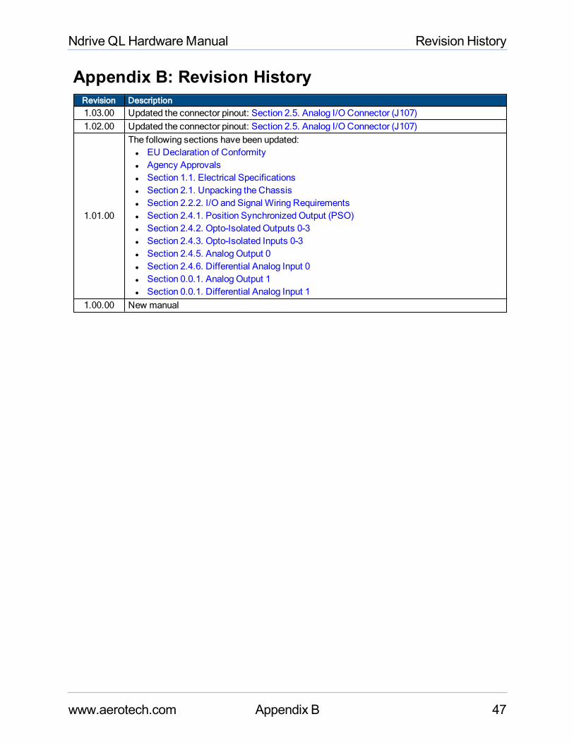
Ndrive QLHardwareManual Revision History
Appendix B: Revision HistoryRevision Description1.03.00 Updated the connector pinout: Section 2.5. Analog I/O Connector (J107)1.02.00 Updated the connector pinout: Section 2.5. Analog I/O Connector (J107)
1.01.00
The following sections have been updated:l EU Declaration of Conformityl Agency Approvalsl Section 1.1. Electrical Specificationsl Section 2.1. Unpacking the Chassisl Section 2.2.2. I/O and Signal Wiring Requirementsl Section 2.4.1. Position Synchronized Output (PSO)l Section 2.4.2. Opto-Isolated Outputs 0-3l Section 2.4.3. Opto-Isolated Inputs 0-3l Section 2.4.5. Analog Output 0l Section 2.4.6. Differential Analog Input 0l Section 0.0.1. Analog Output 1l Section 0.0.1. Differential Analog Input 1
1.00.00 New manual
www.aerotech.com Appendix B 47

Revision History Ndrive QLHardwareManual
48 Appendix B www.aerotech.com
This page intentionally left blank.
www.aerotech.com Index 49
Index2
2014/35/EU 7
A
Altitude 18
Ambient Temperature 18
C
Check chassis for loose or damaged parts /hardware 44
Check for fluids or electrically conductivematerial exposure 44
Cleaning 44
Continuous Output Current 16
D
Declaration of Conformity 7
Digital Output Specifications 28
dimensions 17
E
Electrical Specifications 16
Environmental Specifications 18
F
Functional Diagram 15
fuse 43
G
Global Technical Support 2
H
High-Speed Data Capture 16
Humidity 18
I
Input Frequency 16
Input Power 16
Input Voltage 16
inspect 19
inspect all cables and connections 44
Inspect cooling vents 44
Inspection 44
Installation and Configuration 19
M
Mechanical Design 17
P
Peak Inrush Current 16
Peak Output Current 16
Piezo Actuator Output Voltage 16
Pollution 18
Power Supply 16
PS2815-4 Opto-Device Specifications 30
PSO Output Sources 26
Q
Quick Installation Guide 11
Quick Start Connections 11
S
S1 22
Sensor Resolution 16
Servo Loop Update 16
shipping damage 19
Support 2
T
Technical Support 2
U
unit weight 17
Use 18
V
Voltage Resolution 16
W
Warm Up Time 16
Ndrive QLHardwareManual Index

Index Ndrive QLHardwareManual
50 Index www.aerotech.com
This page intentionally left blank.