navy mic primer
TRANSCRIPT
Investigation of Metastable Interstitial Composite (MIC) Materials for
Electrically Initiated Lead Free Primers
(SERDP Project Number PP 1183)
Naval Air Warfare Center Weapons Division – China Lake
Phil Dixon
15 July 2004
Approved for public release; distribution is unlimited.

This report was prepared under contract to the Department of Defense Strategic Environmental Research and Development Program (SERDP). The publication of this report does not indicate endorsement by the Department of Defense, nor should the contents be construed as reflecting the official policy or position of the Department of Defense. Reference herein to any specific commercial product, process, or service by trade name, trademark, manufacturer, or otherwise, does not necessarily constitute or imply its endorsement, recommendation, or favoring by the Department of Defense.
This report has been reviewed by the Naval Air Warfare Center Weapons Division – China Lake Public Affairs Office and is approved for public release; distribution is unlimited. This report has been reviewed and is approved for publication. Mr. George P. Dixon /S/
Head, Energetic Materials and Component Development Branch Code 478400D Mr. Ronald W. Jones /S/ Energetics Project Office Code 470000D Mr. Steven E. Fowler /S/
Associate Dept Head for Energetics, Weapons and Energetics Dept Code 470000D Mrs. Doris Lance /S/ Date: 14 July 04
Public Affairs Officer, NAVAIR China Lake Code 750000D/E
REPORT DOCUMENTATION PAGE Form Approved OMB No. 0704-0188
Public reporting burden for this collection of information is estimated to average 1 hour per response, including the time for reviewing instructions, searching existing data sources, gathering and maintaining the data needed, and completing and reviewing the collection of information. Send comments regarding this burden estimate or any other aspect of this collection of information, including suggestions for reducing this burden, to Washington Headquarters Services, Directorate for Information Operations and Reports, 1215 Jefferson Davis Highway, Suite 1204, Arlington, VA 22202-4302, and to the Office of Management and Budget, Paperwork Reduction Project (0704-0188), Washington, D.C. 20503. 1. AGENCY USE ONLY (Leave Blank) 2. REPORT DATE 3. REPORT TYPE AND DATES COVERED
10 July 2004 Final; May 2001 – April 2002 4. TITLE AND SUBTITLE 5. FUNDING NUMBERS Investigation of Metastable Interstitial Composite (MIC) Materials for Electrically Initiated Lead Free Primers (SERDP Project Number PP 1183) (U) 6. AUTHOR(S) George P. Dixon
MIPR No. W74RDV10253924
7. PERFORMING ORGANIZATION NAME(S) AND ADDRESS(ES) 8. PERFORMING ORGANIZATION REPORT NUMBER
Naval Air Warfare Center Weapons Division China Lake, CA 93555-6100
NAWCWD Informal Technical Report
9. SPONSORING/MONITORING AGENCY NAME(S) AND ADDRESS(ES) 10. SPONSORING/MONITORING AGENCY REPORT NUMBER
SERDP and ESTCP 901 N. Stuart St. Suite 303 Arlington, VA 22203-1853
11. SUPPLEMENTARY NOTES 12a. DISTRIBUTION/AVAILABILITY STATEMENT 12b. DISTRIBUTION CODE
Approved for public release; distribution unlimited
13. ABSTRACT (Maximum 200 words)
(U) The objective of Environmental Research and Development Program (SERDP) Project Number PP 1183, “Investigation of Metastable Interstitial Composite (MIC) Materials for Electrically Initiated Lead Free Primers,” was to demonstrate the feasibility of eliminating lead styphnate based energetic materials in medium caliber electric primers through the use of MIC based energetic materials.
(U) Before the end of this SERDP Exploratory Development Program (SEED), the Navy was able to demonstrate
the ability to fire 20mm ‘all up rounds’ (AURs) using these experimental MIC-based Lead Free Electric Primers (LFEPs). This adequately demonstrated the feasibility of the Navy’s proposed LFEP configuration and provided the impetus to prepare proposals for follow-on research into this technology.
14. SUBJECT TERMS 15. NUMBER OF PAGES
27 Metastable Interstitial Composite (MIC), Lead-Free Electric Primer, Nano Aluminum 16. PRICE CODE
17. SECURITY CLASSIFICATION OF REPORT
18. SECURITY CLASSIFICATION OF ABSTRACT
19. SECURITY CLASSIFICATION OF THIS PAGE
20. LIMITATION OF ABSTRACT
UNCLASSIFIED UNCLASSIFIED UNCLASSIFIED SAR NSN 7540-01-280-5500 Standard Form 298 (Rev. 2-89) Prescribed by ANSI Std. 239-18 29-102

UNCLASSIFIED SECURITY CLASSIFICATION OF THIS PAGE (When Data Entered)
Standard Form 298 Back (Rev. 2-89) Security Classification of This Page
UNCLASSIFIED
i
Table of Contents List of Acronyms . . . . . . . . . . . . . . . . . . . . . . . . . . . . . . . . . . . . . . . . . . . . . . . . . . . . . ii List of Figures / Tables . . . . . . . . . . . . . . . . . . . . . . . . . . . . . . . . . . . . . . . . . . . . . . . . iii Acknowledgements . . . . . . . . . . . . . . . . . . . . . . . . . . . . . . . . . . . . . . . . . . . . . . . . . . . iv Executive Summary . . . . . . . . . . . . . . . . . . . . . . . . . . . . . . . . . . . . . . . . . . . . . . . . . . . 1 Objective . . . . . . . . . . . . . . . . . . . . . . . . . . . . . . . . . . . . . . . . . . . . . . . . . . . . . . . . . . . . 2 Background . . . . . . . . . . . . . . . . . . . . . . . . . . . . . . . . . . . . . . . . . . . . . . . . . . . . . . . . . . 2 Materials and Methods . . . . . . . . . . . . . . . . . . . . . . . . . . . . . . . . . . . . . . . . . . . . . . . . 3 Results / Accomplishments . . . . . . . . . . . . . . . . . . . . . . . . . . . . . . . . . . . . . . . . . . . . . 15 Conclusions / Recommendations . . . . . . . . . . . . . . . . . . . . . . . . . . . . . . . . . . . . . . . . . 19

ii
List of Acronyms AUR All Up Round
BTL Ballistics Test Laboratory
DoD Department of Defense
ESD Electro-Static Discharge
ESTCP Environmental Security Technology Certification Program
FPS Feet per Second
LANL Los Alamos National Laboratory
LCAAP Lake City Army Ammunition Plant
LFEP Lead Free Electric Primer
mfd Microfarad [Unit of Electrical Capacitance]
MIC Metastable Interstitial [or Intermolecular] Composite
MT Molybdenum Trioxide (MoO3)
NAWCWD Naval Air Warfare Center Weapons Division
Pb Lead
PETN Pentaerythritol Tetranitrate
PVC Poly-Vinyl Chloride
SEED SERDP Exploratory Development
SERDP Strategic Environmental Research & Development Program
SOP Standard Operating Procedure
iii
Figures Figure 1 Conventional Electric Primer Configuration 6
Figure 2 Alternate Exploding Foil Electric Primer Configuration 8
Figure 3 Lead Free Primer Rams / Dies Tooling 9
Figure 4 Lead Free Primer Pressing Operation 10
Figure 5 Cartridge / Primer Test Firing Fixture 12
Figure 6 Lead Free Primer Fire Volts Box 13
Figure 7 Photo Transistor ‘First Light’ Detector 14
Figure 8 Flame Pictures for M52AB1 and LFEP Primers 17
Tables
Table 1 Composition of MIC Material Delivered to Navy 5
Table 2 LFEP Test Firing Data Collection Sheet 11
Table 3 LFEP Primer Electrical Impedance Measurements 18
iv
Acknowledgements
The following individuals and organizations contributed in significant ways to the successful completion of this program: Naval Air Warfare Center Weapons Division Ms. Christina Allen Mr. Al Boyack Mr. Calvin Clayson Mr. Lee Hardt Mr. Larry Johnson Dr. Shirley Kidner Mr. Pat Nalley Mr. Brent Reese Mrs. Antonella Thompson Mr. Don Thompson Mr. Danny Wooldridge Technanogy Company Dr. Chris Aumann Dr. Rob Dye Lake City Army Ammunition Plant Production Office Personnel
1
Executive Summary Through the influence and leadership of national organizations such as the Strategic Environmental Research and Development Program (SERDP) and the Environmental Protection Agency (EPA), the Department of Defense (DoD) has acknowledged the need to minimize and, where possible, eliminate the use of environmentally objectionable materials in the production and use of military weapons systems. One of the critical environmental needs associated with military ordnance is to eliminate the use of heavy metals such as lead (Pb). The U. S. Army accepted this challenge for small caliber ammunition several years ago and established the ‘Green Ammunition’ Program. One of the elements of this effort was to eliminate the use of lead (Pb) in percussion primers for small caliber gun ammunition. The U. S. Navy, which holds a key patent in the area of substituting Metastable Interstitial [or Intermolecular] Composite (MIC) materials for the environmentally objectionable lead styphnate and barium nitrate normally used as the primary energetic components of percussion primers, subsequently proposed to engage parallel problems associated with the use of lead (Pb) in electric primers for medium caliber gun ammunition. The various MIC compositions are fundamentally a mixture of nano-aluminum and an appropriate oxidizer, in this case molybdenum trioxide (MT). The SERDP Office favorably reviewed the Navy’s proposal and established the subject SERDP Exploratory Development (SEED) effort referred to in this document as the Lead Free Electric Primer (LFEP) program. This document summarizes the activities and results of this twelve month / $100K LFEP SEED program. The selected technical approach for the subject SEED effort was a relatively simple substitution of MIC materials, and other amendments, for the environmentally objectionable lead (Pb) based energetic materials currently used in the production of medium caliber electric primers. The general configuration of this experimental primer, including the metal parts, was virtually identical to that used in the fabrication of the currently operational M52A3B1 electric primer used in U. S. military 20mm ammunition. One of the earliest efforts in the SEED program was to procure MIC materials from an appropriate vendor. Following the completion of the Navy’s mandatory ‘New Material’ safety tests, the preparation of appropriate operating procedures, the fabrication of test equipment and the assembly of test items, a number of differently configured 20mm LFEP primers were test fired using typical electrical voltage / current pulses. Although it was not possible within the time and funding constraints to fully investigate all of the questions associated with the use of MIC as an energetic material in medium caliber electric primers, the results of the program did result in the development of two different and functional LFEP configurations. Before the end of the SEED effort, the Navy was able to demonstrate the ability to fire 20mm ‘all up rounds’ (AUR’s) using these experimental MIC based LFEP’s. This adequately demonstrated the feasibility of the Navy’s proposed LFEP configuration and provided the impetus to prepare proposals for follow-on research into this technology.
2
It should be noted that one of the principle outcomes of the LFEP SEED effort was the recognition of the need to more fully study and understand the basic characteristics of MIC materials and the other amendments used in the lead free primer configuration. This conclusion was based on the observation of a number of unpredictable and unexplainable behaviors of the MIC material and the test items during the loading / testing processes. Following the successful completion of the LFEP effort and the required technical briefings and documentation / planning process, the SERDP Office reviewed the follow-on proposals and elected to continue with the research by establishing a three year follow-on ‘Full’ SERDP program focused on more fully exploring the application of MIC technology for primer use.
Objective The objective of the subject program was to demonstrate the feasibility of eliminating lead styphnate based energetic materials in medium caliber electric primers through the use of MIC based energetic materials. If successful, this program would serve to significantly reduce the health and environmental issues associated with the production, test, operational use, demilitarization and disposal of military ammunition utilizing these types of components. Although it is beyond the scope of this time and funds limited SEED effort, the ultimate end product of any follow-on development program would be a safe and affordable electric primer that does not depend on the use of lead (Pb) as a component and provides equal or better performance across the full spectrum of environmental and operational conditions when compared to current electric primers.
Project Background The DoD has acknowledged that heavy metal contamination is a critical environmental problem and has accepted the responsibility for reducing the use of heavy metals, including lead (Pb), in the design, manufacture and operational use of its munitions. Approximately eight years ago, the Naval Air Warfare Center Weapons Division (NAWCWD) worked cooperatively with Dr. Joe Martin of the Los Alamos National Lab (LANL) to identify applications for the MIC materials that Dr. Martin and his co-workers were producing in their laboratory. Mr. Phil Dixon and Mr. Don Thompson, employees of the NAWCWD, and Dr. Martin subsequently demonstrated the feasibility of using the MIC material as a direct substitute for lead styphnate in percussion primers. Shortly after applying, a patent (U.S. Patent Number 5,717,159, dated 10 February 1998) was awarded for this novel approach. As the principal custodian of the patent, the Navy is currently in the process of licensing this technology to industry. Approximately five years ago the U.S. Army, in cooperation with the Strategic Environmental Research and Development Program (SERDP), the Environmental Security Technology Certification Program (ESTCP) and other sponsors, established the “Green Bullet” program, primarily focused on eliminating the use of lead (Pb) in the production of projectiles for small caliber ammunition. This effort also included the objective of eliminating the use of lead (Pb) and barium nitrate in small caliber percussion primers. The Army’s percussion primer efforts
3
have since that time been centered on the substitution of MIC materials, along with other amendments, for the normal lead styphnate / barium nitrate compounds. This program has been underway for approximately six years now and has enjoyed a reasonable measure of success. The Army predicts that they will be placing completely lead (Pb) free small caliber ammunition into operational use in the not too distant future. The NAWCWD recognized a similar need to eliminate the use of lead (Pb) in the electrically initiated family of medium caliber ammunition primers. Since all three U.S. military Services use 20mm ammunition utilizing electrically initiated primers, it was noted that this round of ammunition would be a good candidate as the focus for the proposed effort. A proposal for the establishment of a $100K / twelve month long SEED program was subsequently submitted to the SERDP Office in the spring of 2000. This proposal was favorably reviewed, and as a result the NAWCWD received supporting funds at the end of January 2001 and the Navy’s Lead Free Electric Primer (LFEP) SEED program was commenced.
Materials and Methods Due to the time and funding constraints associated with SEED efforts, it was initially decided to take a relatively simplistic approach and limit the LFEP project efforts to a direct substitution of the MIC materials for the lead styphnate based energetic material normally employed in conventional electrically initiated primers. This approach was modified during latter stages of the SEED effort to include a relatively novel approach for initiating electrical primers. Descriptions of both the conventionally configured primer and the alternate primer configuration will be described in subsequent sections of this report. The MIC materials employed in the LFEP program were purchased directly from Technanogy, a venture capitalist corporation established by Dr. Joe Martin after his retirement from LANL. This source for the MIC was chosen for several reasons. First, it was known that the nano particle aluminum being produced and sold by Technanogy was produced using the same techniques that were the basis of the original and successful Navy / LANL percussion primer patent. Second, it was noted that Technanogy enjoys an excellent reputation for producing consistently high quality materials. Third, Technanogy agreed to mix their nano-aluminum material with the MT oxidizer to produce the necessary MIC materials and ship it to us ready for use. This relieved the Navy of the necessity of bearing the cost for establishing safety approved mixing processes at China Lake. Technanogy also agreed to depart in some small ways from their conventional MIC production processes to accommodate the need to prepare electrically conductive materials. This consisted of adding an additional ingredient, either carbon black or acetylene black, to the mixture. A more complete description of this mixing requirement is included in the next paragraph. Finally, with Technanogy being located in southern California, a relatively short distance from the NAWCWD China Lake facility, shipping issues were also minimized. With a high degree of confidence, the Navy was of the opinion that the basic MIC materials that had been utilized in previous percussion primer applications, containing only nano-particle aluminum and MT, were not going to be electrically conductive, a key requirement for the conventional electrically initiated primer configuration. For this reason, the Navy provided Technanogy with several samples of carbon black material as well as a sample of acetylene black
4
that was in conformance with MIL-A-3850. This MIL-A-3850 compliant acetylene black is what is currently being used in the production of the lead styphnate based primer mix utilized in the M52A3B1 primer. The M52A3B1 electrically initiated primer is currently used in all U.S. produced 20mm ammunition. These carbon-based materials were to be mixed in with the nano-particle aluminum and the MT to provide the necessary electrical characteristics. Several different ratios of carbon black and acetylene black were tested. It was discovered early in the LFEP effort that the only carbon material that provided the needed electrical properties was the acetylene black that was in conformance with the MIL-A-3850. It should also be noted here that Technanogy observed chemical changes in the MT during the time period that they were using it to prepare the MIC for delivery to the Navy. This MT, purchased from the Climax Company, was displaying color changes from an almost pure white color to a shade of light blue / green. (Note: This phenomenon was later analyzed / studied and it was determined that such color changes could be the result of either exposure to sunlight and the resultant formation of sub-oxides or due to hydration and the subsequent shift from the monoclinic molecular form to the orthorhombic form. In this instance, the cause was likely due to the hydration of the MT.) The compositions of the various MIC materials prepared by Technanogy for delivery to the Navy are described in Table 1. For both shipping and handling purposes, the materials were classified as ‘flammable solids’ (classification 4.1.c). The products of combustion for MIC materials are primarily inert “solids”. Although it is possible to produce small amounts of gas pressure due to the heating of the surrounding atmosphere and the temporary vaporization of metal; in fact, virtually no gas is evolved during the combustion process. In comparison, the lead styphnate compounds currently used in primers, both percussion and electrically initiated, are classified as primary explosives and produce gaseous by-products capable of producing very high pressures in confined volumes. The primary hazard associated with the MIC materials is related to the extremely large release of thermal energy that can produce very serious flash burns to the eyes and exposed skin. For this reason, the materials are handled very carefully, utilizing appropriate personal protection equipment. The pre-formed metal parts and other materials required to fabricate the lead-free primer test items were obtained through the generosity of the Lake City Army Ammunition Plant (LCAAP), located in Independence, Missouri. The LCAAP is a government owned / contractor operated production facility currently being managed by the Alliant Techsystems Company. These primer components and materials included such items as: cups, buttons, insulators, coated paper, support cups and ‘dry assemblies’. A cross-sectional view illustrating the ‘design’ of the conventionally configured lead-free primer utilizing these components is shown in Figure 1. Currently operational electrical primers, such as the M52A3B1 primer, are initiated through ohmic heating of the primer mix. This heating takes place when the high voltage and high current, capacitively coupled electrical firing pulse is delivered to the primer button and travels to the ‘grounded’ primer cup through the electrically conductive primer mix. Because of the high speed with which this high-energy electrical pulse is delivered to the primer button, the temperature of the primer mix is elevated up to ignition temperatures very quickly. The specified maximum action time for an M52A3B1 primer is 0.3 milliseconds.
5
Table 1 – Composition of MIC Material Delivered to Navy
NEF Shipping Summary to NAWCWD Aluminum Oxidizer Carbon Black (CB)
Mix Designator Ingredients Type* Type Type Lot No. % CB (Wt %)
Average Reaction
Rate (m / sec)
Target** Oxidizer to Metal Ratio
Amount (Grams)
1st MIC Shipment
NEF01-1 / SF19-1 Al / MoO3 A A 0.0 312 1.2A 4.6 NEF02-1 / SF19-2 Al / MoO3 / CB A A Mogul - L GP 2882 1.2 335 1.2A 5.0 NEF01-2 / SF20-1 Al / MoO3 B A 0.0 488 1.2A 5.0
2nd MIC Shipment
NEF02-2 / SF22-1 Al / MoO3 / CB A Mogul – L GP 2882 4.1 122 1.2A 5.0 NEF02-3 / SF23-1 Al / MoO3 / CB A Mogul – L GP 2882 2.5 140 1.2A 5.4 NEF02-4 / SF24-1 Al / MoO3 / CB A Chevron - Phillips 1-146 3.3 169 1.2A 5.0 NEF03-1 / SF25-1 Al A 7.5 NEF04-1 / SF25-2 MoO3 A 7.5 NEF05-1 / SF25-3 CuO B 5.0
3rd MIC Shipment
NEF01-3 / SF26-1 Al / MoO3 C A 0.0 296 1.2A*** 5 NEF06-1 / SF27-1 Al / CuO C B 0.0 470 1.2B 5 NEF02-5 / SF28-1 Al / MoO3 / CB C A Chevron - Phillips 1-146 3.4 224 1.2A*** 5 NEF07-1 / SF29-1 Al / Cu) / CB C B Chevron - Phillips 1-146 3.4 204 1.2B 5
4th MIC Shipment
NEF03-2 / SF30-1 Al A 15 NEF04-2 / SF30-2 MoO3 C 15
* Aluminum particles were in the range of 40-50 nanometers in size ** Oxidizer to metal ratio is adjusted to account for oxide layer on aluminum particles *** Type A molybdenum trioxide appeared to be ‘aging’ (turning color from white to light blue-green)
6
Figure 1 – Conventional Electric Primer Configuration
Paper
Button
Cup
Insulator
Insulator
Cup
Support Cup
Energetic Material Shell
Propellant
Shell
Support Cup
Energetic Material Paper
Cup
Button
Insulator
7
The conventionally configured LFEP primer is similarly initiated. This explains the importance of adding the appropriate amount of acetylene black to the primer mix to enhance its electrical properties. The success of the conventionally configured LFEP partly contradicts the experience of others where they had attempted to ignite a loose ‘bed’ of MIC powder by placing a hot wire within the ‘bed’. They had reported that the MIC material was not initiated in spite of the wire reaching red-hot temperatures. One very important functional feature of any ammunition primer is the need to meet the AUR action time. Action time is defined as the time interval between the point in time at which the primer is struck; or in the case of electrical primers, the time when the firing pulse is applied to the primer, and when the projectile exits the muzzle of the barrel. According to specification MIL-P-1394, the specified action time for 20mm ammunition is 4.0 milliseconds. This is an especially important performance feature of any externally powered gun since delays in action time can result in a round being initiated after the gun bolt has unlocked and the round is being extracted from the chamber. This type of event typically destroys major components of the gun and produces seriously dangerous conditions for the aircraft and the personnel manning the aircraft. As noted earlier in this report, during the latter stages of the SEED program, it was decided to investigate an alternate configuration for the lead-free primers. This action was taken because of some difficulties that were encountered with the initiation of the conventional primer configuration. This approach utilized an exploding foil phenomenology that has been exploited in other applications. This alternate design, utilizing virtually the same metal parts used in the conventional configuration, is illustrated in Figure 2. As can be seen, a thin and narrow strip of aluminized Mylar material is added to the primer in such a way that it provides an electrically conductive path between the button and the cup of the primer. Conductive adhesives were used to attach one end of the aluminized Mylar to the button and the other end to the interior surface of the cup. The MIC material was then pressed into place over the Mylar strip in a fashion identical to that used in the conventional primer configuration. Placement of the coated paper on top of the MIC material and the pressing of the support cup to hold all of the materials in place were the final steps in the fabrication of these alternately configured items. In operation, the pulse of electrical energy used to initiate the alternately configured primer vaporizes the aluminum and discharges the molten material into the MIC, thereby igniting it. This approach offers a very robust and highly reliable method of initiating the primer mix and early indications are that it might not be as demanding as far as the condition / quality of the MIC is concerned. It should be noted here that it is not necessary that the MIC material utilized in this configuration be electrically conductive. This alternate configuration will continue to be investigated during future follow-on efforts. The tooling required to assemble the LFEP primers was designed and built at China Lake. A photograph of the various rams and dies are shown in Figure 3. Figure 4 illustrates one of the pressing operations utilized in the assembly process. All of these assembly operations were conducted in accordance with pre-existing NAWCWD Specific Operational Procedures (SOP’s). Due to the sensitive nature of the MIC materials, there were a limited number of personnel and facilities that were authorized to handle and test the primers. The assembly of the alternate aluminized Mylar configuration was accomplished through some additional handwork to prepare
8
Figure 2 – Alternate (Exploding Foil) Electric Primer Configuration
9
Figure 3 – Lead Free Primer Rams / Dies Tooling
10
Figure 4 - Lead Free Primer Pressing Operation the Mylar strips and bond them to the button and cup using electrically conductive adhesive prior to being charged with the MIC material. The initial test items were fabricated using conventional primer metal parts obtained from the LCAAP. The approach used in their fabrication consisted of a direct substitution of the MIC material for the conventional lead styphnate mix. The amount of MIC used in each of the primers and the consolidation pressure(s) used in their fabrication was based on production practices associated with the conventional M52A3B1 electric primer and preliminary data obtained from the Army on how they had constructed the small caliber percussion primers. Some of the configuration details are listed in Table 2. A test fixture to hold and fire primed cases was designed and fabricated at China Lake. A picture of this fixture is shown in Figure 5. This fixture had been built with a slot in its side to
11
Table 2 – LFEP Test Firing Data Collection Sheet
MIC Primer Configuration Details Nikon
Mylar O-Scope Files
Photo Transistor Time
To: Test No. Type Primer Mix Mix Weight
(mg) Loading
Pressure (ksi) Primer Height
(Inches) YES / NO L or R
Primer Resistance
(Ohms)
Firing Voltage (Volts)
Selected Capacitance
(mfd) Film
Speed Aperture (f / no.)
Shutter (Seconds)
Frame No. Chan 1 Chan 2 First Rise Peak
Audible Primer
FunctionNotes
1 M52 57K 348 1 160 5.6 5 3 0 1 92 596 YES 1 2 M52 43.4K 247.4 1 800 1.4 5 1 2 3 94 628 YES 1 3 M52 16.13K 247.8 1 800 1.4 5 3 4 5 92 550 YES 1 4 MIC NEF02-4 SF24-1 100 1 NO .316M 350 1 400 2.8 5 4 6 7 NO 1 5 MIC NEF02-4 SF24-1 100 1 NO .518M 351 1 400 2.8 5 5 8 9 NO 1 6 M52 16.95K 350 1 400 2.8 5 6 10 11 96 572 YES 1 7 MIC NEF02-4 SF24-1 125 6 NO 148K 350 1 400 2.8 5 3 12 13 NO 1 8 MIC NEF02-4 SF24-1 100 10 NO .600M 349 4 400 2.8 5 5 14 15 NO 1,2 9 MIC NEF02-4 SF24-1 125 10 YES ? 37.7 350 4 400 2.8 5 6 16 17 124 1026 YES 1
10 MIC NEF02-4 SF24-1 125 10 NO 89K 349 4 400 2.8 5 7 18 19 NO 1 11 MIC NEF02-3 SF24-1 125 10 NO 1.034M 350 4 400 2.8 5 20 21 NO 3 12 MIC NEF02-2 SF24-1 125 10 NO 2.199M 349 4 400 2.8 5 22 23 NO 3 13 M52 53.8K 201.7 4 400 2.8 5 11 24 25 88 564 YES 3 14 M52 10.81K 202.5 4 800 4 5 2 26 27 96 582 YES 3 15 MIC NEF02-2 SF22-1 100 ? YES R 0.5 347 4 800 4 5 3 28 29 172 908 YES 3 16 MIC NEF02-2 SF22-1 100 ? YES L 212.8 347 4 800 2.8 5 4 30 31 140 938 YES 3 17 MIC NEF02-3 SF23-1 100 ? YES R 0.2 345 4 800 5.6 5 5 32 33 NO 3 18 MIC NEF02-3 SF23-1 100 ? YES L 47.1 346 4 800 5.6 5 6 34 35 NO 3 19 MIC NEF02-3 SF23-1 100 ? YES L 23.8 346 4 800 5.6 5 7 36 37 NO 3 20 MIC NEF02-4 SF24-1 100 ? YES R 0.2 346 4 800 5.6 5 8 38 39 NO 3 21 M52 7.45K 346 4 800 5.6 5 9 40 41 78 536 YES 3
Notes: 1) Phototransistor @ 125mV/box, 500µs/box 2) Powder Dried @ 75C under Vacuum 3) Changed Phototransistor to 50mV/box
12
Figure 5 – Cartridge / Primer Test Firing Fixture facilitate the viewing of the primer flash if and when cartridge cases had been cut-off to reduce their length. However, the output of all of the primers, both the standard M52A3B1 primer and the LFEP test items, was so robust, that it was not necessary to reduce the length of the cartridge cases prior to testing. The electrical firing pulse used to initiate the primers was generated using a ‘special’ capacitive discharge fire volts box that had some extra features associated with it. It has a rheostat that enables the user to adjust the output from zero to 450 volts DC. It also offers the operator the option of five different capacitor values: 0 mfd, 1 mfd, 2 mfd, 4 mfd and 40 mfd. The LFEP firing tests typically utilized DC voltages in the range of 250 volts to 400 volts. Capacitor values were also varied during the tests. A photograph of the fire volts box is shown in Figure 6. Instrumentation used in the ’primer only’ tests was minimal. A multi-channel recording oscilloscope was used to verify that we were generating an appropriate fire volts pulse. The oscilloscope provided voltage levels and pulse duration values. It also recorded and displayed light levels and timing data received from the phototransistor described in the following paragraph.
13
Figure 6 - Lead Free Primer Fire Volts Box A phototransistor was used to ‘stare’ into the mouth of the cartridge case and provide quantitative data on the output of the primer in terms of ‘light’. This data allowed the relative comparison of the outputs of the various primer configurations as well as provide some relative timing information. This timing information is believed to be a very valuable factor in the process of optimizing the action time of the LFEP primers. A photograph of this simple measurement device is shown in Figure 7. Finally, three cameras were located in the test chamber to visually record the output of the primers. These photographic devises consisted of two single lens reflex cameras and a conventional video camera. The two film cameras were used in the ‘open shutter’ mode. Since the test chamber (room) was darkened, it was possible to remotely open the shutter of the film cameras prior to initiating the test item and have them record the overall output of the primers. The shape and duration of these primer flashes are thought to be an important factor in future efforts to optimize the outputs of the LFEP primers. These cameras were placed in two different locations to provide two different perspectives of the primer flash. One camera was located above the test set-up and looked down on the test set-up with a checkerboard pattern on the floor in view. The other camera was positioned alongside and slightly behind the test set-up. Both of these cameras functioned as expected and provided both qualitative and pseudo-quantitative data.
14
Figure 7 – Photo Transistor ‘First Light’ Detector The video camera used in the ‘primer only’ tests was conventional video device operating at the normal 30 frames / 60 field per second rate. Although the duration of the primer flash is very short, this camera was able to produce usable images that were incorporated into some of the briefing packages. This video camera was positioned above the test fixture and was looking down on the test set-up. The primer test process was conducted in phases. The initial tests were “primer only” functional tests and did not include any gun propellant or projectiles. These tests were conducted using both standard M52A3B1 primers and the various configurations of LFEP test items pressed into previously unused 20mm cartridge cases. These primed cartridge cases were taken to the appropriate test facility where an attempt was made to fire them. Efforts to validate the functionality of the test set-up by first firing conventional M52A3B1 primers were successful. Following a relatively small number of successful “primer only” / empty cartridge case tests, it was dictated by program schedules that we attempt to fire a small number of AUR’s using the sub-optimized LFEP primers. These tests were partially successful in the sense that the alternate (exploding foil) configured rounds functioned but the conventionally configured rounds did not. Moreover, due to apparent instrumentation problems at the Ballistics Test Laboratory (BTL), it was not possible to collect and record full and complete interior ballistics data for these rounds. The exploding foil rounds appeared to produce very good action times that were similar to the conventional PGU-27/B round being used for baseline comparison purposes. However, it should
15
be noted here that chamber pressures and muzzle velocities were not consistently recorded for any of the rounds. (Note: It was learned after these tests that the data collection system at the BTL was being ‘triggered’ by false signals and subsequently recording unreliable data. This data collection system has been replaced by a new automated / self checking system since that time.)
Results / Accomplishments
Due to the nature of the SEED program, testing and subsequent data collection was done on a sporadic basis. The first meaningful MIC material related tests were conducted by Technanogy prior to the delivery of the first batch of MIC materials. These tests were performed to measure the burning rate of the MIC in a non-consolidated (‘tap density’) form. Based on inputs from Technanogy, these initial materials burned at rates as low as 122 meters per second (400 FPS) and as high as 488 meters per second (1600 FPS). These same measurements were made on subsequent batches of MIC materials as they were being prepared. This reaction velocity data can be viewed in Table 1. One of the first test related LFEP activities to take place at the NAWCWD was the material safety tests. These measurements are mandated by the NAWCWD’s New Material Committee and consist of standardized friction, impact and electro-static discharge (ESD) tests. Standard Pentaerythritol Tetranitrate (PETN) is used as the basis of comparison for this series of go / no go tests. A copy of the test report documenting these safety evaluations is included as Appendix A to this report. In summary, the results of the tests indicated that the material was very sensitive to both friction and ESD. Surprisingly, the material was not found to be highly sensitive to impact. Of course the key aspect of the LFEP SEED effort was the laboratory testing of the candidate primer designs. Firing tests were conducted in three phases. The first phase was a simple effort to determine whether the LFEP primers were going to function or not. These tests were conducted by pressing the conventionally configured LFEP primers into empty cartridge cases and attempting to initiate them through electrical impulses from the fire volts box. These phase I tests were conducted without the use of any instrumentation. The second series of tests were again relatively simplistic functionality tests of the primers by themselves. The difference being that photographic and phototransistor data was collected on this series of tests. The third and final phase of testing was done on ‘AUR’s. These tests were designed to determine whether the LFEP primers were capable of adequately initiating the propellant bed of a typical 20mm round of ammunition. An equally important aspect of the third phase of testing was to begin collecting interior ballistics information on the non-optimized LFEP test items. Test firing data for both the ‘primer only’ tests and the ‘AUR’ tests are included on a single data collection sheet, a copy of which is included as Table 2. As stated above, the phase I series of tests were performed on ‘primers only’ and did not include the use of any propellant or projectiles. Attempts to initiate primers produced from the first batch of MIC were not successful. Following the delivery of the second and third batches of MIC materials, additional sets of both conventionally configured and alternate design primers were fabricated and tested. These tests,
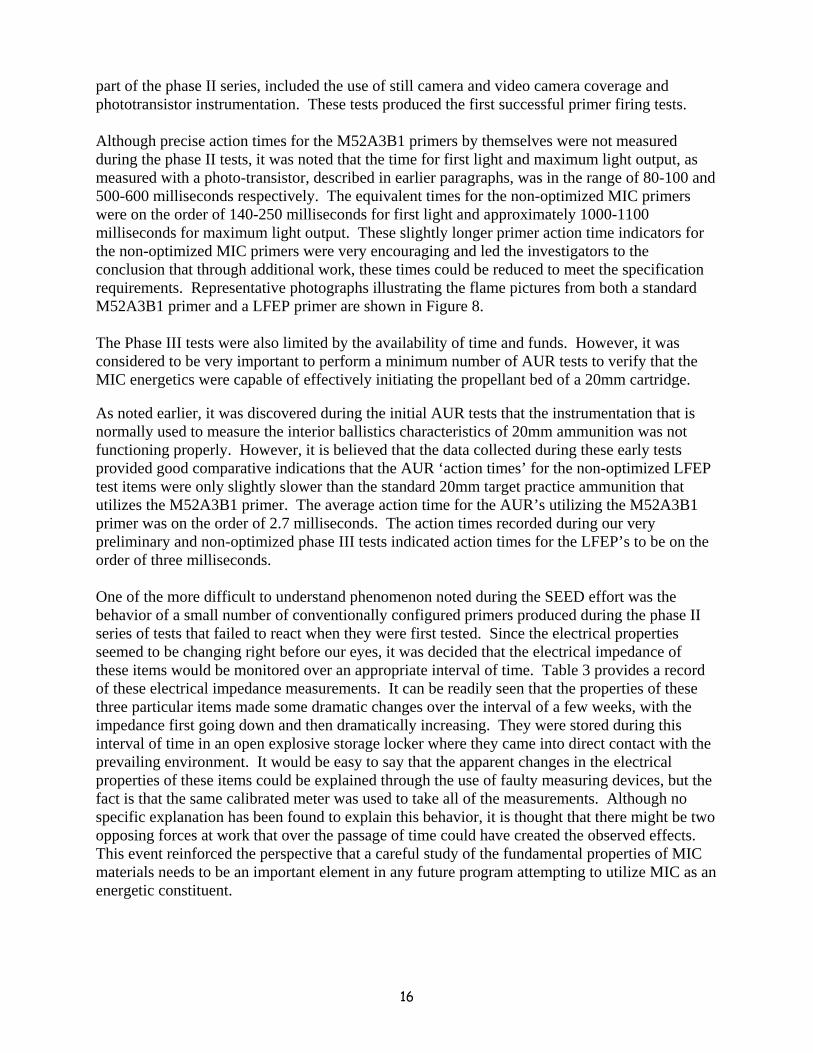
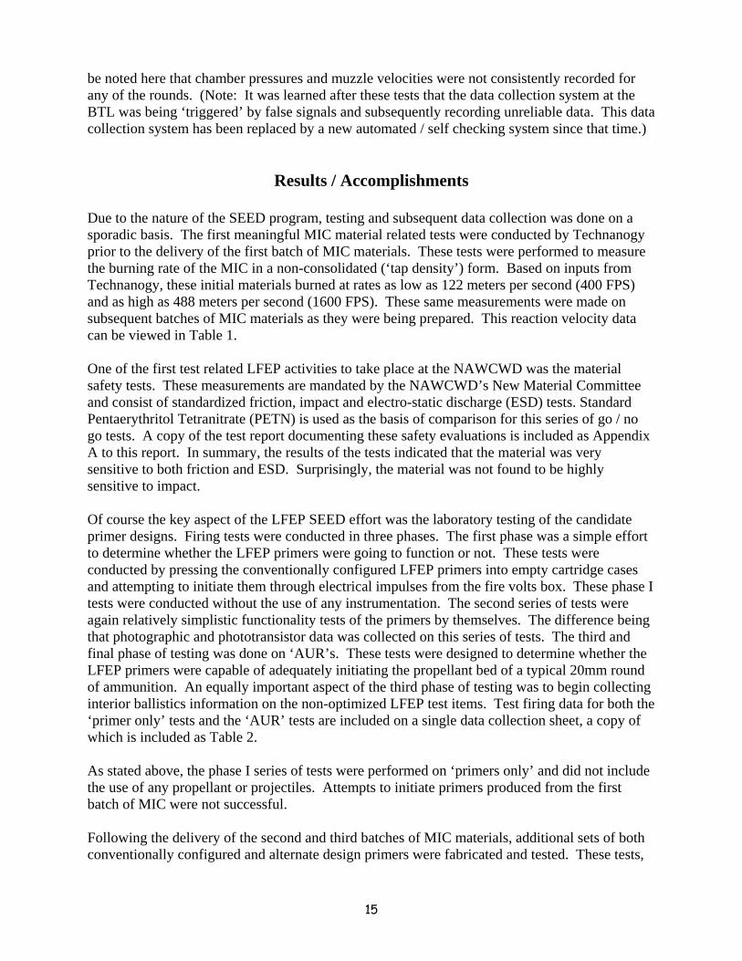
16
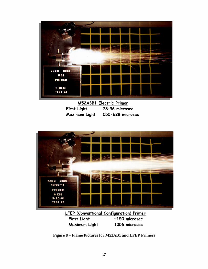
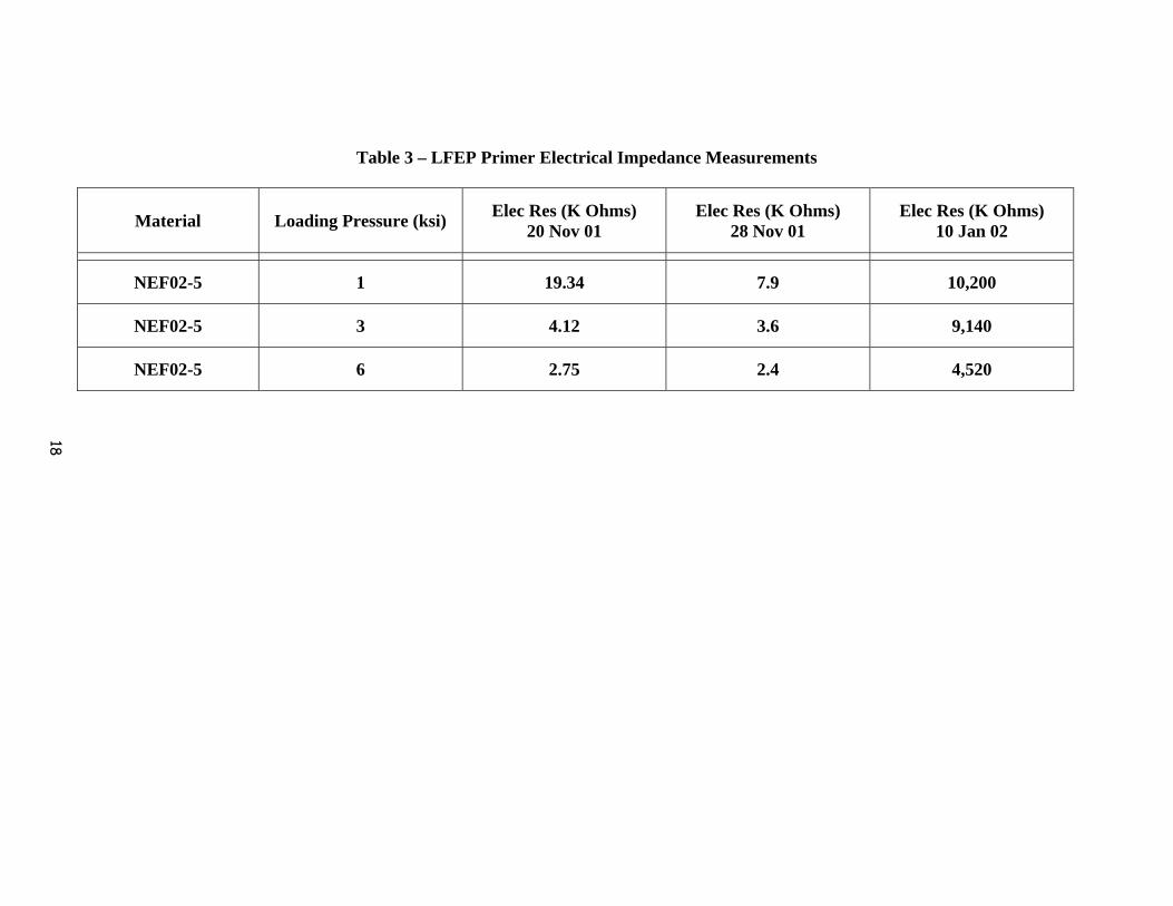
part of the phase II series, included the use of still camera and video camera coverage and phototransistor instrumentation. These tests produced the first successful primer firing tests. Although precise action times for the M52A3B1 primers by themselves were not measured during the phase II tests, it was noted that the time for first light and maximum light output, as measured with a photo-transistor, described in earlier paragraphs, was in the range of 80-100 and 500-600 milliseconds respectively. The equivalent times for the non-optimized MIC primers were on the order of 140-250 milliseconds for first light and approximately 1000-1100 milliseconds for maximum light output. These slightly longer primer action time indicators for the non-optimized MIC primers were very encouraging and led the investigators to the conclusion that through additional work, these times could be reduced to meet the specification requirements. Representative photographs illustrating the flame pictures from both a standard M52A3B1 primer and a LFEP primer are shown in Figure 8. The Phase III tests were also limited by the availability of time and funds. However, it was considered to be very important to perform a minimum number of AUR tests to verify that the MIC energetics were capable of effectively initiating the propellant bed of a 20mm cartridge. As noted earlier, it was discovered during the initial AUR tests that the instrumentation that is normally used to measure the interior ballistics characteristics of 20mm ammunition was not functioning properly. However, it is believed that the data collected during these early tests provided good comparative indications that the AUR ‘action times’ for the non-optimized LFEP test items were only slightly slower than the standard 20mm target practice ammunition that utilizes the M52A3B1 primer. The average action time for the AUR’s utilizing the M52A3B1 primer was on the order of 2.7 milliseconds. The action times recorded during our very preliminary and non-optimized phase III tests indicated action times for the LFEP’s to be on the order of three milliseconds. One of the more difficult to understand phenomenon noted during the SEED effort was the behavior of a small number of conventionally configured primers produced during the phase II series of tests that failed to react when they were first tested. Since the electrical properties seemed to be changing right before our eyes, it was decided that the electrical impedance of these items would be monitored over an appropriate interval of time. Table 3 provides a record of these electrical impedance measurements. It can be readily seen that the properties of these three particular items made some dramatic changes over the interval of a few weeks, with the impedance first going down and then dramatically increasing. They were stored during this interval of time in an open explosive storage locker where they came into direct contact with the prevailing environment. It would be easy to say that the apparent changes in the electrical properties of these items could be explained through the use of faulty measuring devices, but the fact is that the same calibrated meter was used to take all of the measurements. Although no specific explanation has been found to explain this behavior, it is thought that there might be two opposing forces at work that over the passage of time could have created the observed effects. This event reinforced the perspective that a careful study of the fundamental properties of MIC materials needs to be an important element in any future program attempting to utilize MIC as an energetic constituent.
17
Figure 8 – Flame Pictures for M52AB1 and LFEP Primers
M52A3B1 Electric Primer
First Light 78–96 microsec Maximum Light 550-628 microsec
LFEP (Conventional Configuration) Primer First Light ~150 microsec Maximum Light 1056 microsec
18
Table 3 – LFEP Primer Electrical Impedance Measurements
Material Loading Pressure (ksi) Elec Res (K Ohms) 20 Nov 01
Elec Res (K Ohms) 28 Nov 01
Elec Res (K Ohms) 10 Jan 02
NEF02-5 1 19.34 7.9 10,200
NEF02-5 3 4.12 3.6 9,140
NEF02-5 6 2.75 2.4 4,520
19
In addition to this final technical report, a number of different illustrations, viewgraph packages, photos, video clips and hardware items, including test fixtures, test item assembly tooling and miscellaneous test support equipment can be viewed as deliverables under this effort.
Conclusions / Recommendations This SEED program clearly demonstrated a number of key factors that support the concept of using MIC materials as a substitute for the heavy metal materials that are normally used in the production of electrically initiated primers. These demonstrated points include the following: - MIC materials can be made electrically conductive - MIC can be safely handled and loaded into typical electrical primer metal parts - MIC loaded primers can be initiated by ordinary aircraft gun fire volts inputs - MIC loaded primers can effectively initiate the propellant bed of 20mm cartridges
In addition: - Two different MIC loaded electrically initiated primers configurations were identified - Additional insights into the behavior of MIC materials were gained / shared - Potential technical issue areas were identified that require additional attention - Necessity of determining the reaction rate of the MIC to assure that it can meet cartridge action time requirements - Critically important that the basic chemical characteristics of MIC be thoroughly studied A proposal, prepared in accordance with existing SERDP policy, will be prepared and submitted to the Pollution Prevention pillar of the SERDP office. This proposal will provide the necessary technical and management details to allow the program to be objectively evaluated. Following a favorable review of this proposal, the follow-on program will be executed in accordance with the prescribed schedule and within the allocated budget. Following a successful completion of the follow-on ‘Full’ SERDP LFEP program, the effort will be continued; either through the transition to an ESTCP effort or to an engineering development program that will ultimately lead to a full production effort, placing these improved items in the hands of the various Service users. In summary, it is believed that all of the significant objectives of the subject SEED program were achieved. The concept of substituting MIC for the ‘normal’ lead (Pb) based energetic materials in a medium caliber electric primer was shown to be feasible. Examples of unresolved primer configuration issues include: precise composition of the MIC powder, the quantity of MIC and the consolidation pressures to be used in placing the MIC in the primer cup. The optimization of these, and other, factors is expected to produce a primer that will reliably and effectively ignite the propellant

20
bed of the subject ammunition. It is recommended that the current SEED effort be transitioned to a ‘Full’ SERDP program. This will allow the investigators to more thoroughly evaluate the concept and verify that a configuration meeting all of the functional / operational and safety requirements can be established for this fundamentally important ordnance component.