navigĀcijas sistĒma, komunikĀciju sistĒma
TRANSCRIPT
Antonijas ielā 18, LV1010, Rīga, Latvija, tālr.:+371 67332236, fax.:+371 67333670 e-mail: [email protected]
Līguma Nr.: P/2007 – 103 Contract #:
Pasūtītājs: Valsts aizsardzības militāro objektu un iepirkumu centrs
Client: State Centre for Defense Military Sites and Procurement reģ. Nr. 90009225180 Ernestīnes iela 34, Rīga, LV-1046, Latvija
Projektētājs: “PRO VIA”, SIA Designer: reģ. Nr. 40003372696 Antonijas iela 18/1, Rīga, LV-1010, Latvija
Objekts: LR AM NACIONĀLO BRUŅOTO SPĒKU GAISA Object: SPĒKU AVIĀCIJAS BĀZES REKONSTRUKCIJA
RECONSTRUCTION OF AIR FORCE BASE OF NATIONAL ARMED FORCES
Būvprojekta marka: LA Construction design mark:
Sējums LA NAV / Volume LA NAV
LIDLAUKA APRĪKOJUMS AIRFIELD FACILITIES
NAVIGĀCIJAS SISTĒMA, KOMUNIKĀCIJU SISTĒMA NAVIGATION SYSTEM, COMMUNICATIONS SYSTEM
TEHNISKĀS SPECIFIKĀCIJAS TECHNICAL SPECIFICATIONS
Rīga, 2013.
Antonijas ielā 18, LV1010, Rīga, Latvija, tālr.:+371 67332236, fax.:+371 67333670 e-mail: [email protected]
Līguma Nr.: P/2007 – 103 Contract #:
Pasūtītājs: Valsts aizsardzības militāro objektu un iepirkumu centrs
Client: State Centre for Defense Military Sites and Procurement reģ. Nr. 90009225180 Ernestīnes iela 34, Rīga, LV-1046, Latvija
Projektētājs: “PRO VIA”, SIA Designer: reģ. Nr. 40003372696 Antonijas iela 18/1, Rīga, LV-1010, Latvija
Objekts: LR AM NACIONĀLO BRUŅOTO SPĒKU GAISA Object: SPĒKU AVIĀCIJAS BĀZES REKONSTRUKCIJA
RECONSTRUCTION OF AIR FORCE BASE OF NATIONAL ARMED FORCES
Būvprojekta marka: LA Construction design mark:
Sējums LA NAV / Volume LA NAV
LIDLAUKA APRĪKOJUMS AIRFIELD FACILITIES
NAVIGĀCIJAS SISTĒMA, KOMUNIKĀCIJU SISTĒMA NAVIGATION SYSTEM, COMMUNICATIONS SYSTEM
TEHNISKĀS SPECIFIKĀCIJAS TECHNICAL SPECIFICATIONS
Valdes loceklis: Normunds Kalniņš Member of the Board: Projekta vadītāja: Inese Beitāne Project Manager: LA daļas vadītājs: Evija Leitlande Manager of LA part:
Rīga, 2013.

VISPĀRĪGĀ DAĻA
GENERAL PART
LR AM NACIONĀLO BRUŅOTO SPĒKU GAISA SPĒKU AVIĀCIJAS BĀZES REKONSTRUKCIJA
RECONSTRUCTION OF AIR FORCE BASE OF NATIONAL ARMED FORCES
LIDLAUKA APRĪKOJUMS
AIRFIELD FACILITIES
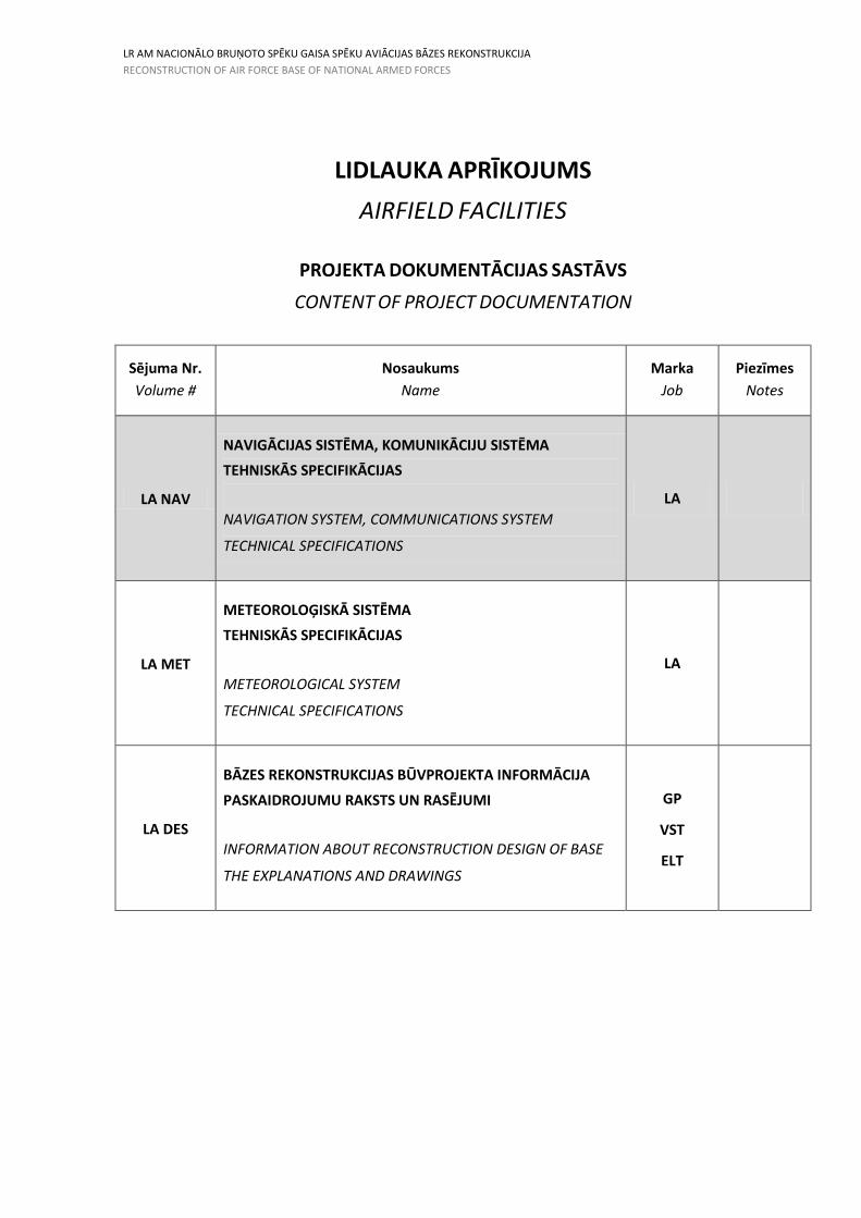
PROJEKTA DOKUMENTĀCIJAS SASTĀVS
CONTENT OF PROJECT DOCUMENTATION
Sējuma Nr.
Volume #
Nosaukums
Name
Marka
Job
Piezīmes
Notes
LA NAV
NAVIGĀCIJAS SISTĒMA, KOMUNIKĀCIJU SISTĒMA
TEHNISKĀS SPECIFIKĀCIJAS
NAVIGATION SYSTEM, COMMUNICATIONS SYSTEM
TECHNICAL SPECIFICATIONS
LA
LA MET
METEOROLOĢISKĀ SISTĒMA
TEHNISKĀS SPECIFIKĀCIJAS
METEOROLOGICAL SYSTEM
TECHNICAL SPECIFICATIONS
LA
LA DES
BĀZES REKONSTRUKCIJAS BŪVPROJEKTA INFORMĀCIJA
PASKAIDROJUMU RAKSTS UN RASĒJUMI
INFORMATION ABOUT RECONSTRUCTION DESIGN OF BASE
THE EXPLANATIONS AND DRAWINGS
GP
VST
ELT
LR AM NACIONĀLO BRUŅOTO SPĒKU GAISA SPĒKU AVIĀCIJAS BĀZES REKONSTRUKCIJA
RECONSTRUCTION OF AIR FORCE BASE OF NATIONAL ARMED FORCES
Nr.
#Nosaukums Name
Lapa / Rasējuma Nr.
Page / Drawing #
Rasējuma mērogs
Drawing Scale
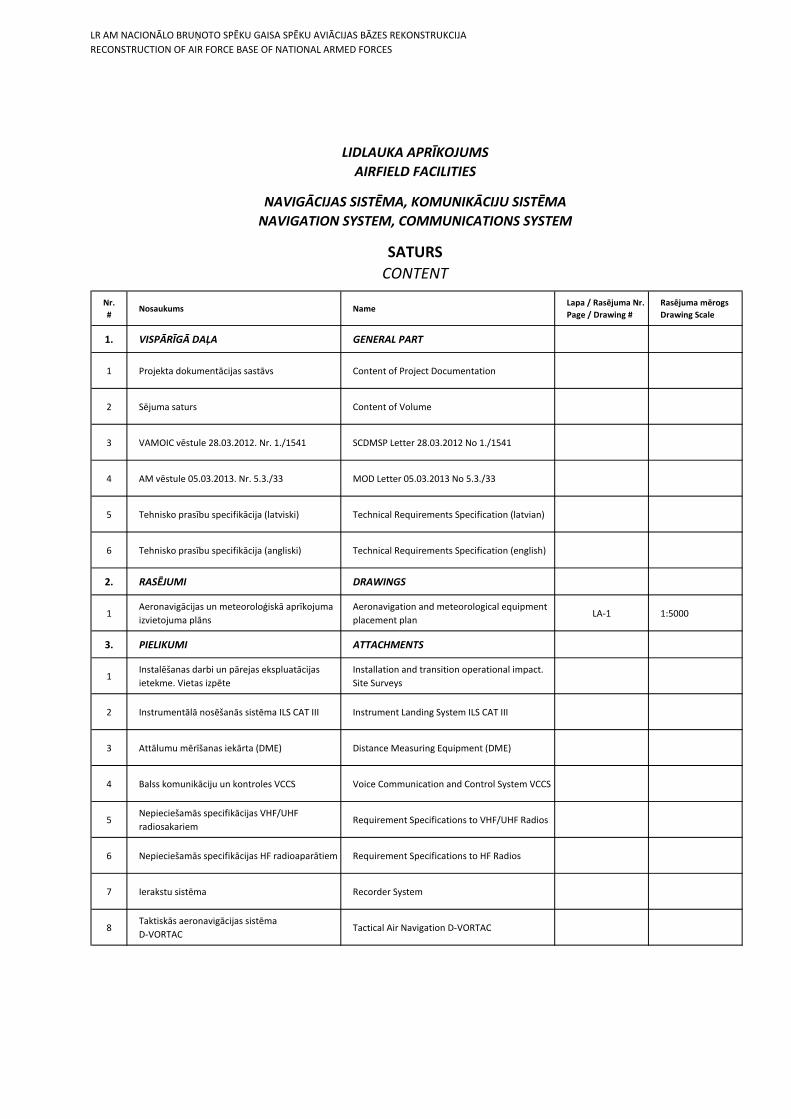
1. VISPĀRĪGĀ DAĻA GENERAL PART
1 Projekta dokumentācijas sastāvs Content of Project Documentation
2 Sējuma saturs Content of Volume
3 VAMOIC vēstule 28.03.2012. Nr. 1./1541 SCDMSP Letter 28.03.2012 No 1./1541
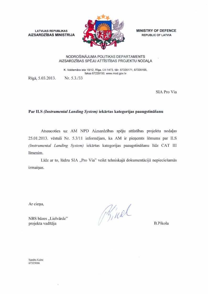
4 AM vēstule 05.03.2013. Nr. 5.3./33 MOD Letter 05.03.2013 No 5.3./33
5 Tehnisko prasību specifikācija (latviski) Technical Requirements Specification (latvian)
6 Tehnisko prasību specifikācija (angliski) Technical Requirements Specification (english)
2. RASĒJUMI DRAWINGS
1Aeronavigācijas un meteoroloģiskā aprīkojuma
izvietojuma plāns
Aeronavigation and meteorological equipment
placement planLA-1 1:5000
3. PIELIKUMI ATTACHMENTS
1Instalēšanas darbi un pārejas ekspluatācijas
ietekme. Vietas izpēte
Installation and transition operational impact.
Site Surveys
2 Instrumentālā nosēšanās sistēma ILS CAT III Instrument Landing System ILS CAT III
3 Attālumu mērīšanas iekārta (DME) Distance Measuring Equipment (DME)
4 Balss komunikāciju un kontroles VCCS Voice Communication and Control System VCCS
5Nepieciešamās specifikācijas VHF/UHF
radiosakariem Requirement Specifications to VHF/UHF Radios
6 Nepieciešamās specifikācijas HF radioaparātiem Requirement Specifications to HF Radios
7 Ierakstu sistēma Recorder System
8Taktiskās aeronavigācijas sistēma
D-VORTAC Tactical Air Navigation D-VORTAC
NAVIGĀCIJAS SISTĒMA, KOMUNIKĀCIJU SISTĒMA
NAVIGATION SYSTEM, COMMUNICATIONS SYSTEM
SATURS
CONTENT
LIDLAUKA APRĪKOJUMS
AIRFIELD FACILITIES

Prasības piedāvājumam
TEHNISKO PRASĪBU SPECIFIKĀCIJA
TECHNICAL_REQUIREMENTS NAV_LAT 2013 10 17.10.13
Lpp. 1
SATURA RĀDĪTĀJS
1. IEVADS .................................................................................................................. 3
2. KOPĒJAIS PĀRSKATS ............................................................................................... 4
2.1 LIELVĀRDES GSB KOPĒJĀ SISTĒMAS KONCEPCIJA ........................................................ 4
2.1.1 PAMATPRASĪBAS................................................................................................... 4
2.1.2 SISTĒMAS LIELVĀRDEI ........................................................................................... 4
2.2 SISTĒMAS KONCEPCIJAS PAMATA PRASĪBAS ............................................................... 5
2.2.1 NAVIGĀCIJAS SISTĒMA .......................................................................................... 5
2.2.2 KOMUNIKĀCIJU SISTĒMA ...................................................................................... 5
3. SERVISI ................................................................................................................ 13
3.1 INSTALĒŠANAS DARBI UN PĀREJAS EKSPLUATĀCIJAS IETEKME ................................ 13
3.1.1 Vispārējās prasības ............................................................................................. 13
3.2 MĀCĪBAS .................................................................................................................... 13
3.2.1 Ievads .................................................................................................................. 13
3.2.2 Vispārējas prasības. ............................................................................................ 14
3.2.3 Mācību dokumentācija ....................................................................................... 14
3.2.4 Mācību telpas un aprīkojums.............................................................................. 15
3.2.5 Operatīvā personāla mācības ............................................................................. 15
3.2.6 Tehniskā personāla mācības ............................................................................... 15
3.2.7 Piedāvājums no Pretendenta .............................................................................. 16
3.3 KVALITĀTES NODROŠINĀŠANA .................................................................................. 17
3.3.1 Vispārējās prasības ............................................................................................. 17
3.3.2 Kvalitātes kontrole un pārbaude ........................................................................ 17
3.4 PIEŅEMŠANAS PĀRBAUDES ....................................................................................... 19
3.4.1 Iekārtu pārbaude rūpnīcā (FAT) .......................................................................... 19
3.4.2 Iekārtu pārbaude uz vietas (SAT) ........................................................................ 19
3.4.3 Iekārtu pārbaude rūpnīcā (FAT) .......................................................................... 19
3.4.4 Iekārtu pārbaude uz vietas (SAT) ........................................................................ 20
3.5 GARANTIJA ................................................................................................................. 22
3.5.1 Vispārējās prasības ............................................................................................. 22
3.6 REZERVES DAĻAS ........................................................................................................ 23
3.6.1 Primārās rezerves daļas ...................................................................................... 23
3.6.2 Rezervēšanas līmenis .......................................................................................... 23
3.6.3 Rezerves daļu apraksts ....................................................................................... 23
3.6.4 Rezerves daļu saraksts ........................................................................................ 23
3.6.5 Garantijas ........................................................................................................... 23
3.7 DOKUMENTĀCIJA ....................................................................................................... 23
3.7.1 Vispārējās prasības ............................................................................................. 23
3.7.2 Iekārtu dokumentācija ........................................................................................ 24
3.7.3 Programmnodrošinājuma dokumentācijai ......................................................... 25
Prasības piedāvājumam
TEHNISKO PRASĪBU SPECIFIKĀCIJA
TECHNICAL_REQUIREMENTS NAV_LAT 2013 10 17.10.13
Lpp. 2
3.7.4 Daudzpusīga dokumentācija .............................................................................. 25
3.8 PRASĪBAS IEKĀRTĀM UN PROGRAMMNODROŠINĀJUMAM ..................................... 26
3.8.1 Prasības programmnodrošinājumam ................................................................. 26
3.8.2 Prasības iekārtām ............................................................................................... 26
3.9 BŪVDARBI .................................................................................................................. 28
3.9.1 Vispārējās prasības ............................................................................................. 28
3.10 TEHNISKĀS APKOPES PRASĪBAS .............................................................................. 28
3.10.1 Vispārīgi .............................................................................................................. 28
3.10.2 Sistēmas projektēšanas apsvērumi ..................................................................... 28
3.10.3 Uzturēšanas operācijas ....................................................................................... 29
3.10.4 Profilaktiskā apkope ........................................................................................... 30
3.10.5 Koriģējošā apkope .............................................................................................. 30
3.10.6 Apkopes nodrošināšana ...................................................................................... 31
Prasības piedāvājumam
TEHNISKO PRASĪBU SPECIFIKĀCIJA
TECHNICAL_REQUIREMENTS NAV_LAT 2013 10 17.10.13
Lpp. 3
1. IEVADS
Šis dokuments nosaka operacionālo un tehnisko prasību specifikācijas valsts komunikāciju un navigācijas (CNS) sistēmai Lielvārdes gaisa spēku bāzes (GSB) modernizācijas projektā. Šīs prasības ir obligātas un Pretendentam tās ir stingri jāievēro. Jebkura nozīmīga neatbilstība šīm pamatprasībām var kalpot par pamatu izslēgšanai no tālākas izskatīšanas.
Kopējais Lielvārdes GSB CNS/ MET sistēmas mērķis ir nodrošināt Latvijas gaisa spēku darbību NATO ietvaros. Tāpēc atbilstība piemērojamajiem ICAO un NATO standartiem ir obligāta.
Piedāvātajām sistēmām jābūt ar mūsdienīgu dizainu, sevi pierādījušām un izmantotām NATO dalībvalstīs Eiropā. Pretendentam jābūt pieredzei vismaz trīs lidostu modernizācijā NATO dalībvalstīs šajā dokumentā minētajā līmenī.
Kur tas ir iespējams, kopējai sistēmai jābūt bāzētai uz modernu, augstas kvalitātes, komerciālu darbderīgu (COTS) tehnoloģiju.
Pretendentam jānodrošina detalizētu atbilstību formu, kurā ir identificēta pilnīga atbilstība, daļēja atbilstība (ar paskaidrojumiem) vai neatbilstība prasībām, kas minētas šajā konkursa dokumentā un tam pievienotajās specifikācijās.
Pras bas pied v jumam
TEHNISKO PRAS BU SPECIFIK CIJA
TECHNICAL_REQUIREMENTS NAV_LAT 2013 nepilns.doc16.04.13
Lpp. 4
2. KOP JAIS P RSKATS
2.1 LIELV RDES GSB KOP J SIST MAS KONCEPCIJA
2.1.1 PAMATPRAS BAS
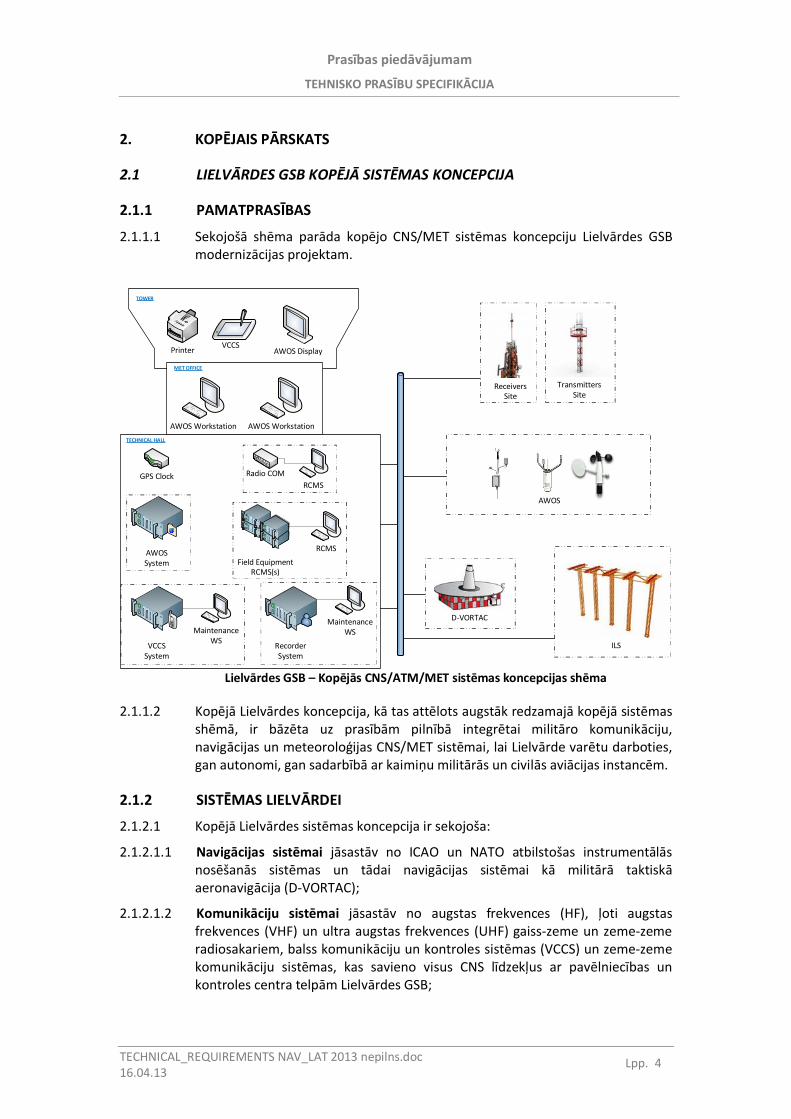
2.1.1.1 Sekojoš sh ma par da kop jo CNS/MET sist mas koncepciju Lielv rdes GSBmoderniz cijas projektam.
AWOS Workstation AWOS Workstation
Radio COMRCMS
AWOS DisplayVCCS
Printer
GPS Clock
AWOSSystem
RecorderSystem
VCCSSystem
Field EquipmentRCMS(s)
RCMS
MaintenanceWSMaintenance
WS
TOWER
MET OFFICE
TECHNICAL HALL
AWOS
TransmittersSite
D-VORTAC
ReceiversSite
ILS
Lielv rdes GSB – Kop j s CNS/ATM/MET sist mas koncepcijas sh ma
2.1.1.2 Kop j Lielv rdes koncepcija, k tas att lots augst k redzamaj kop j sist massh m , ir b z ta uz pras b m piln b integr tai milit ro komunik ciju,navig cijas un meteorolo ijas CNS/MET sist mai, lai Lielv rde var tu darboties,gan autonomi, gan sadarb b ar kaimi u milit r s un civil s avi cijas instanc m.
2.1.2 SIST MAS LIELV RDEI
2.1.2.1 Kop j Lielv rdes sist mas koncepcija ir sekojoša:
2.1.2.1.1 Navig cijas sist mai j sast v no ICAO un NATO atbilstošas instrument l snos šan s sist mas un t dai navig cijas sist mai k milit r taktiskaeronavig cija (D-VORTAC);
2.1.2.1.2 Komunik ciju sist mai j sast v no augstas frekvences (HF), oti augstasfrekvences (VHF) un ultra augstas frekvences (UHF) gaiss-zeme un zeme-zemeradiosakariem, balss komunik ciju un kontroles sist mas (VCCS) un zeme-zemekomunik ciju sist mas, kas savieno visus CNS l dzek us ar pav lniec bas unkontroles centra telp m Lielv rdes GSB;
Prasības piedāvājumam
TEHNISKO PRASĪBU SPECIFIKĀCIJA
TECHNICAL_REQUIREMENTS NAV_LAT 2013 10 17.10.13
Lpp. 5
2.1.2.1.3 Meteoroloģiskajai sistēmai jāsastāv no automātiskās laika apstākļu novērojumu sistēmas, kas var automātiski nodrošināt faktisko laika apstākļu novērojumu rezultātus, tai skaitā: vēja virzienu un vēja ātrumu, aviācijas redzamību un redzamības tālumu uz skrejceļa (RVR), mākoņu apakšējās robežas augstumu un mākoņu daudzumu, atsevišķas laika apstākļu parādības, atmosfēras spiedienu (QNH, QFE), temperatūru un relatīvo mitrumu (rasas punkta temperatūru). Ietverot vizuālos novērojumus automātiskajos ziņojumos, sistēmas operators tiks nodrošināts ar pilnīgu laika apstākļu novērojumu datu apkopojumu.
2.2 SISTĒMAS KONCEPCIJAS PAMATA PRASĪBAS
2.2.1 NAVIGĀCIJAS SISTĒMA
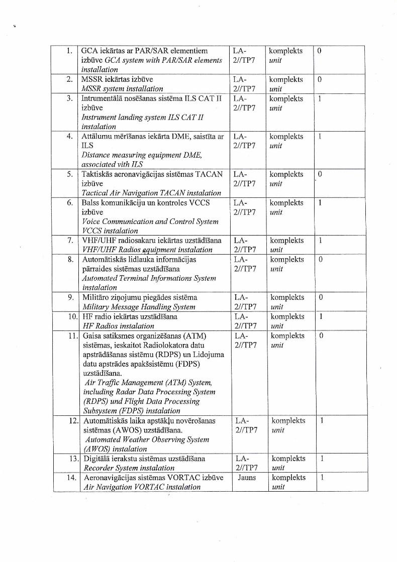
2.2.1.1 Lielvārdes GSB navigācijas sistēmai jāsastāv no sekojošām apakšsistēmām:
2.2.1.1.1 III kategorijas ILS kursa radiobāka;
2.2.1.1.2 III kategorijas ILS glisāde;
2.2.1.1.3 DME;
2.2.1.1.4 Taktiskā aeronavigācija (D-VORTAC).
Prasību specifikācijas ILS sistēmai ir detalizēti minētas 2. pielikumā. Prasību specifikācijas DME sistēmai ir detalizēti minētas 3. pielikumā. Prasību specifikācijas D-VORTAC sistēmai ir detalizēti minētas 8. pielikumā.
2.2.2 KOMUNIKĀCIJU SISTĒMA
2.2.2.1 Komunikāciju sistēmai jāietver sevī sekojošas divas apakšsistēmas:
2.2.2.1.1 Gaisa satiksmes kontroles torņa komunikāciju sistēma
2.2.2.1.2 Informatīvā komunikāciju sistēma (CIS)
2.2.2.2 Gaisa satiksmes kontroles torņa komunikāciju sistēma
2.2.2.2.1 Gaisa satiksmes kontroles torņa (ATC-T) komunikāciju sistēmai jāsastāv no sekojošām apakšsistēmām:
2.2.2.2.1.1 Balss sakaru kontroles sistēma (VCCS);
2.2.2.2.1.2 VHF/UHF radiosakari (raidītāji un uztvērēji);
2.2.2.2.1.3 Balss ziņojumu ieraksta sistēma;
2.2.2.2.1.4 GPS laika sistēma;
2.2.2.2.1.5 Lidlauka tālvadības un uzraudzības sistēma.
Prasību specifikācijas VCCS sistēmai ir detalizēti minētas 4. pielikumā.
2.2.2.2.2 Jābūt izveidotām un nodrošinātām sekojošām operatoru darba vietām:
2.2.2.2.2.1 ATC-T Torņa Kontrole
Prasības piedāvājumam
TEHNISKO PRASĪBU SPECIFIKĀCIJA
TECHNICAL_REQUIREMENTS NAV_LAT 2013 10 17.10.13
Lpp. 6
2.2.2.2.2.2 ATC-T Zemes kontrole
2.2.2.2.2.3 ATC-T Palīgpozīcija
2.2.2.2.2.4 1. Pieejas kontroles operators
2.2.2.2.2.5 2. Pieejas kontroles operators (apvienots ar vadītāju)
2.2.2.2.2.6 Tehniskā apkalpošana
2.2.2.2.3 Pretendentam jānodrošina trīs (3) gaisa satiksmes kontroles torņa konsoles, divas (2) pieejas kontroles konsoles un viena (1) tehniskās apkalpošanas konsole.
2.2.2.2.4 Izveidotajām konsolēm jānodrošina brīvas, ergonomiskas un efektīvas darbības, kas izslēdz neskaidrības un ļauj dispečeriem pievērsties tieši konkrētajā brīdī nepieciešamajiem lēmumiem. Gaisa satiksmes kontroles torņa dispečeriem paredzētajām konsolēm jābūt izvietotām nodrošinot iespējami labāko skatu no darba pozīcijām uz lidlauka apkārtni.
2.2.2.2.5 Konsolēm jābūt nodrošinātām ar sekojošo:
2.2.2.2.5.1 Iekšējiem 19” skapjiem iekārtu uzstādīšanai
2.2.2.2.5.2 Alumīnija paneļu sistēmu displeju uzstādīšanai uz kustīgiem stiprinājumiem
2.2.2.2.5.3 Vēdināmiem paneļiem
2.2.2.2.5.4 Noņemamiem paneļiem
2.2.2.2.5.5 Atsevišķu elektroenerģijas piegādes sistēmu katram skapim
2.2.2.2.6 Paneļiem zem galda jānodrošina sekojošu iekārtu piederumu uzstādīšanu:
2.2.2.2.6.1 Paneļiem jābūt atveramiem
2.2.2.2.6.2 Mikrofoni
2.2.2.2.6.3 Telefona klausules
2.2.2.2.6.4 Austiņu ligzdas
2.2.2.2.6.5 Lidojumu vadības sistēmas paneļu turētājiem
Prasību specifikācijas VHF/UHF Radiosakariem ir detalizēti minētas 5. pielikumā.
2.2.2.2.7 ATC-T ir nepieciešami sekojoši radiosakari:
2.2.2.2.7.1 Pieci (5) pamata/rezerves VHF-UHF raidītāji
2.2.2.2.7.2 Pieci (5) pamata/rezerves VHF-UHF uztvērēji
2.2.2.2.7.3 Viens (1) ārkārtas VHF-UHF raiduztvērējs ar atsevišķu elektroenerģijas dublēšanu.
2.2.2.2.8 Pieprasītajiem RF filtriem, antenām, zibens aizsardzībai, fīderiem, antenu torņiem un instalāciju materiāliem jābūt nodrošinātiem kā pamatrisinājumiem.
2.2.2.2.9 VHF-UHF raidītājiem un uztvērējiem jābūt nodrošinātiem ar tālvadības kontroli un ekspluatācijas uzraudzības sistēmu un tīkla vadības sistēmu.
2.2.2.2.10 Detalizētas prasību specifikācijas balss ziņojumu ieraksta sistēmai ir sekojošas:
Prasības piedāvājumam
TEHNISKO PRASĪBU SPECIFIKĀCIJA
TECHNICAL_REQUIREMENTS NAV_LAT 2013 10 17.10.13
Lpp. 7
2.2.2.2.10.1 Balss ziņojumu ierakstu sistēmai jāspēj aptvert visas radio, telefonu un operatoru komunikācijas. Ieraksta iespējām jābūt pārmērīgām.
2.2.2.2.10.2 Minimālajam VCSS vietnē instalēto kanālu skaitam ir jābūt četrdesmit astoņi (48). Papildus ieraksta ierīcēm ar vismaz 16 kanāliem jābūt pieejamām pēc pieprasījuma izvietošanai citās vietnēs.
2.2.2.2.10.3 Jābūt nodrošinātām vismaz sekojošām iespējām:
2.2.2.2.10.3.1 Zvanu / radio komunikāciju precīzs ieraksts un arhivēšana
2.2.2.2.10.3.2 Ātrs un viegls zvanu pārskats
2.2.2.2.10.3.3 Pēdējā ierakstītā zvana tūlītēja pieejamība un reproducēšana
2.2.2.2.10.3.4 Atskaņošana neiejaucoties notiekošajā ierakstā
2.2.2.2.10.3.5 Droša zvanu arhivēšana dažādos datu nesējos (HD, DVD, utt.)
2.2.2.2.10.3.6 Tiešsaistes uzraudzība
2.2.2.2.10.3.7 Tīklošanas iespējas
2.2.2.2.10.3.8 Paplašināšanas iespējas
Prasību specifikācijas ziņojumu ieraksta sistēmai ir detalizēti minētas 7. pielikumā.
2.2.2.2.11 Detalizētas prasību specifikācijas GPS laika sistēmai ir sekojošas:
2.2.2.2.11.1 GPS laika sistēmai jābūt izveidotai atbilstoši vai pārsniedzot visas specifikācijas, kas rekomendētas NENA (Nacionālā ārkārtas numuru asociācija) PSAP (Publiskās drošības atbilstības punkts) galvenajā laika standartā (NENA-04-002).
2.2.2.2.11.2 GPS laika sistēma var pieļaut citu NENA specifikācijām atbilstošu iekārtu sinhronizāciju ar laika informāciju, kas tiek saņemta no GPS pavadoņiem.
2.2.2.2.11.3 Galvenajam pulkstenim jāsaņem fiksētu laika un datuma informāciju no globālās pozicionēšanas sistēmas pavadoņiem un jānodrošina UTC (Koordinētais universālais laiks) sinhronizēti dati ATC-T sistēmām dažādās formās. Ir jāizmanto divpadsmit (12) kanālu uztvērējs, kas ir spējīgs sekot divpadsmit (12) pavadoņiem vienlaicīgi, lai gan tikai viena no tiem uztveršana ir nepieciešama precīzu laika datu atspoguļošanai.
2.2.2.2.11.4 Pretendentam ir jābūt atbildīgam par pieprasīto interfeisu nodrošinājumu ar sekojošām sistēmām:
2.2.2.2.11.4.1 VCCS
2.2.2.2.11.4.2 Balss ziņojumu ieraksta sistēma
2.2.2.2.11.4.3 RDPS/FDPS
2.2.2.2.11.4.4 Analogie/Digitālie pulksteņi (vismaz 10 interfeisi)
Prasības piedāvājumam
TEHNISKO PRASĪBU SPECIFIKĀCIJA
TECHNICAL_REQUIREMENTS NAV_LAT 2013 10 17.10.13
Lpp. 8
2.2.2.2.12 Prasību specifikācijas Lidlauka tālvadības kontroles un uzraudzības sistēmai (RCMS) ir sekojošas:
2.2.2.2.12.1 RCMS ir jānodrošina tālvadības uzraudzība un kontrole visām CNS/MET sistēmām, kas uzstādītas Lielvārdē. Pretendentam jāpiedāvā savs risinājums ņemot vērā, ka kopējās sistēmas uzraudzība var tikt veikta no centrālās atrašanās vietas.
2.2.2.2.12.2 Jābūt iekļautai, gan iekārtu (CNS/MET), gan to atrašanās vietu (kursa radiobāka, glisāde, D-VORTAC, MET) kontroles un ekspluatācijas uzraudzības informācijai.
2.2.2.2.12.3 Uzraudzības pozīcijai jāsastāv vismaz no šādām iespējām:
2.2.2.2.12.3.1 Temperatūras uzraudzība
2.2.2.2.12.3.2 Piedūmojuma signalizācijas uzraudzība
2.2.2.2.12.3.3 Elektroapgādes pieejamība
2.2.2.2.12.3.4 Rezerves ģeneratora darbība
2.2.2.2.12.3.5 Rezerves ģeneratora signalizācija
2.2.2.2.12.3.6 Zems degvielas līmenis rezerves ģeneratorā
2.2.2.2.12.3.7 Atvērtu durvju signalizācija
2.2.2.2.12.4 RCMS jāspēj veikt centrālo uzraudzību darbības statusam visiem uz zemes izvietotajiem aviācijas sistēmu elementiem, kas tiek izmantoti iekārtās. Tās galvenais uzdevums ir nodrošināt gaisa satiksmes vadības operatorus ar saprotamu grafisku informāciju par iekārtu saistību ar sistēmas signalizācijas stāvokli.
2.2.2.2.12.5 RCMS ir jābūt piemērojamai dotajā pozīcijā uzstādītajām iekārtām. Grafiskajam lietotāja interfeisam (GUI) jāspēj veikt darbības ar intuitīvo un interaktīvo programmnodrošinājumu.
2.2.2.3 Informatīvā komunikāciju sistēma (CIS)
2.2.2.3.1 Kopējais apraksts
2.2.2.3.1.1 Informatīvās komunikāciju sistēmas konfigurācija ir specifiska katram darbības vietas veidam. Pamatā CIS ir jānodrošina:
2.2.2.3.1.1.1 Nepārtrauktu informatīvo komunikāciju servisu lidostas personālam;
2.2.2.3.1.1.2 Sasaisti ar civilās/militārās aviācijas infrastruktūras informatīvo komunikāciju tīkliem;
2.2.2.3.1.1.3 Tehnisko atbalstu automatizētajai informācijas sistēmai;
2.2.2.3.1.2 Informatīvā komunikāciju sistēma sastāv no sekojošām apakšsistēmām:
2.2.2.3.1.2.1 Komunikāciju informācijas centrs (CIC)
2.2.2.3.1.2.2 Automatizēta informācijas sistēma (AIS)
2.2.2.3.1.2.3 Telefona centrāle (PABX tīkls)
Prasības piedāvājumam
TEHNISKO PRASĪBU SPECIFIKĀCIJA
TECHNICAL_REQUIREMENTS NAV_LAT 2013 10 17.10.13
Lpp. 9
2.2.2.3.1.2.4 Zemes – gaisa – zemes komunikācijas, tai skaitā
2.2.2.3.1.2.4.1 HF-VHF-UHF raidīšanas centrs
2.2.2.3.1.2.4.2 HF-VHF-UHF uztveršanas centrs
2.2.2.3.1.2.5 Tālvadības zeme – gaiss VHF radiosakari
2.2.2.3.1.2.6 Iekārtas (modemi,...), kas nodrošina datu pārraidi no aeronavigācijas sistēmām izmantojot rezervētā optiskā tīkla un vara kabeļa tīkla maģistrāles.
2.2.2.3.1.2.7 Vietējais tīkls (LAN), lai savienotu CIC un AIS darba stacijas ar publiskiem un/vai privātiem tīkliem
2.2.2.3.1.2.8 Optiskās šķiedras / vara kabeļu / bezvadu infrastruktūra, lai savienotu dažādas pozīcijas lidlaukā ar tīkla maģistrāli (t.s. radionavigācijas un novērošanas pozīcijas ar tīkla maģistrāli, radiosakaru radīšanas centru un/vai uztveršanas centru ar tīkla maģistrāli, meteoroloģiskās sistēmas pozīcijas ar tīkla maģistrāli, vietējo telefonu līnijas ar PABX, iekšējie savienojumi ar sistēmām kontroles torni)
2.2.2.3.2 Priekšnoteikumi
2.2.2.3.2.1 Detalizēts CIS apraksts būs pretendenta atbildībā viņa piedāvājumā pēc obligātās vietas izpētes paveikšanas. Vietas izpētes laikā Pircējs nodrošinās pretendentiem iespēju apmeklēt visas šajā projektā iesaistītās pozīcijas. Pircējs paziņos visiem pretendentiem par vietas izpētes datumiem.
Prasību specifikācijas Vietas izpētei detalizēti ir minētas 1. pielikumā.
2.2.2.3.2.2 Komunikāciju informācijas centrs (CIC) jānodrošina ar vadošajām sērijveida (COTS) darba stacijām ar specifisku konfigurāciju.
2.2.2.3.2.3 Standarta programmnodrošinājumam jāsastāv tikai no sekojošiem punktiem:
2.2.2.3.2.3.1 MS Windows Professional (pēdējā versija)
2.2.2.3.2.3.2 MS Office Standard (pēdējā versija)
2.2.2.3.2.3.3 Antivīrusa programmatūra (pēdējā versija)
2.2.2.3.2.4 Automatizētā informācijas sistēma (AIS) ir infrastruktūra, kas nodrošina pieeju informācijai un paredzēta informācijas apstrādei, glabāšanai, atspoguļošanai, pārvietošanai un raidīšanai. AIS jābūt strukturētai tā, lai būtu pieejami divi dažādu veidu pilnīgi neatkarīgi tīkli:
2.2.2.3.2.4.1 Privātais tīkls (Intranet)
2.2.2.3.2.4.2 Publiskais tīkls (Internet)
2.2.2.3.2.5 AIS jānodrošina ar vadošajiem COTS serveriem, darba stacijām, pārslēgšanas un maršrutizācijas iekārtām ar specifisku konfigurāciju.
2.2.2.3.2.6 Standarta programmnodrošinājumam jāsastāv tikai no sekojošiem punktiem:
2.2.2.3.2.6.1 MS Windows Professional (pēdējā versija)
Prasības piedāvājumam
TEHNISKO PRASĪBU SPECIFIKĀCIJA
TECHNICAL_REQUIREMENTS NAV_LAT 2013 10 17.10.13
Lpp. 10
2.2.2.3.2.6.2 MS Office Standard (pēdējā versija)
2.2.2.3.2.6.3 Antivīrusa programmatūra (pēdējā versija)
2.2.2.3.2.7 Telefona centrāle sastāv no PABX tīkla un attiecīgas infrastruktūras.
2.2.2.3.2.8 PABX specifikācijām jābūt bāzētām uz gala lietotāja nodrošināto informāciju attiecībā uz maģistrāļu veidu un skaitu, telefona līniju veidu un skaitu, pavadoņu veidu un skaitu, mezglu skaitu tīklā.
2.2.2.3.2.9 PABX jābūt nodrošinātam ar administrēšanas terminālu(-iem) ar specifisku projekta konfigurāciju.
2.2.2.3.2.10 Zemes – gaisa – zemes komunikāciju sistēma ir uzstādīta HF-VHF-UHF raidīšanas centrā un HF-VHF-UHF uztveršanas centrā.
2.2.2.3.2.11 Raidīšanas centram ir nepieciešamas sekojošas iekārtas:
2.2.2.3.2.11.1 divi (2) HF raidītāji 125W
2.2.2.3.2.11.2 divi (2) HF raidītāji 500W
2.2.2.3.2.11.3 pieci (5) VHF-UHF raidītāji
2.2.2.3.2.12 Uztveršanas centram ir nepieciešamas sekojošas iekārtas:
2.2.2.3.2.12.1 četri (4) HF uztvērēji
2.2.2.3.2.12.2 pieci (5) VHF-UHF uztvērēji
2.2.2.3.2.13 Pieprasītajiem RF filtriem, antenām, zibens aizsardzībai, fīderiem, antenu torņiem un instalāciju materiāliem jābūt nodrošinātiem kā pamatrisinājumiem.
2.2.2.3.2.14 VHF-UHF raidītājiem un uztvērējiem jābūt nodrošinātiem ar tālvadības kontroles un ekspluatācijas uzraudzības sistēmu un tīkla vadības sistēmu.
2.2.2.3.2.15 Radiosakariem jābūt lietojamiem no ATC-T uzstādītās VCCS.
Prasību specifikācijas VHF/UHF radiosakariem detalizēti ir minētas 5. pielikumā. Prasību specifikācijas HF radiosakariem detalizēti ir minētas 6. pielikumā.
2.2.2.3.2.16 Tālvadības zeme – gaiss komunikācijas (vēl zināmas kā paplašinātas amplitūdas VHF radio sistēma) ir priekšmets atsevišķām specifikācijām.
2.2.2.3.2.17 Optiskās šķiedras pamata komunikācijām jānodrošina pieprasītā sasaiste ar civilās/militārās aviācijas infrastruktūras (t.s. citu lidostu, gaisa spēku štāba, vadības un kontroles centra, gaisa spēku virspavēlniecības operatīvā centra – ASOC, utt.) komunikāciju-informācijas tīkliem.
2.2.2.3.2.18 Pamata komunikācijām jābūt savienotām ar visu kopējo CNS/MET sistēmu, lietojot modernus, augstas kapacitātes datu pārraides posmus (optiskā šķiedra, mikroviļņi, utt.).
2.2.2.3.2.19 Pretendentam jāpiedāvā pilnīgs komunikāciju risinājums pēc detalizētas vietas apskates.
Prasības piedāvājumam
TEHNISKO PRASĪBU SPECIFIKĀCIJA
TECHNICAL_REQUIREMENTS NAV_LAT 2013 10 17.10.13
Lpp. 11
2.2.2.3.2.20 Optiskās šķiedras infrastruktūrai jābūt veidotai ar pietiekamu skaitu atsevišķiem šķiedras kabeļiem, izvietotiem pazemes HDPE caurulēs (viena rezerves caurule jāiekļauj turpmākajai attīstībai).
2.2.2.3.2.21 Precīzs optiskās šķiedras kabeļu skaits tiks noskaidrots vietas izpētes laikā.
2.2.2.3.2.22 Jābūt izvietotiem rezerves optiskās šķiedras kabeļiem.
2.2.2.3.2.23 Optiskās šķiedras kabelim jābūt sadalītam optiskajās sadales daļās (ODF). Piegāde optiskās līnijas vienībām jānotiek ar optiskās šķiedras savienojuma auklām.
2.2.2.3.2.24 Katrai no iepriekš minētajām sistēmām (MW radiosakari, optiskās šķiedras līniju termināli un multiplekseri) jābūt nodrošinātām ar atbilstošiem tālvadības tīkla vadības termināliem, kas nepieciešami atbilstošās sistēmas administrēšanai un tālvadības ekspluatācijas uzraudzībai.
2.2.2.3.2.25 Vietējam tīklam (LAN) jābūt bāzētam uz „Ethernet” protokolu (IEEE 802.X). Tīkla topoloģijai jābūt zvaigznes veidā, mezglu un portu skaits katram mezglam tiks definēts vietas izpētes laikā. Centrālajam mezglam jābūt CIC ēkā.
2.2.2.3.2.26 Sasaistēm starp mezgliem jābūt nodrošinātām ar optiskās šķiedras kabeļiem. Optiskās šķiedras infrastruktūrai jābūt veidotai no šķiedras kabeļiem, izvietotiem pazemes HDPE caurulēs (viena rezerves caurule jāiekļauj turpmākajai attīstībai).
2.2.2.3.2.27 Optiskās šķiedras kabelim jābūt sadalītam optiskajās sadales daļās (ODF). Piegāde optiskās līnijas vienībām jānotiek ar optiskās šķiedras savienojuma auklām.
2.2.2.3.2.28 Piemērotām LAN maršrutēšanas iekārtām jābūt bāzētām uz tīkla izmēriem.
2.2.2.3.2.29 Optiskās šķiedras / vara kabeļu / bezvadu infrastruktūra sastāv no nepieciešamajiem kabeļiem, sadales daļām, un/vai komunikāciju iekārtām.
2.2.2.3.2.30 PABX piegādes tīkla tehnoloģijai jābūt no vara pāru kabeļiem.
2.2.2.3.2.31 Vara pāru kabeļiem jābūt sadalītiem galvenajās sadales daļās (MDF) pie ieejas katrā ēkā. Ieejai ēkā jābūt pienācīgi aizsargātai pret zibeni. Iekšējai sadalei uz centrālajām iekārtām un līnijām jābūt no vara pāru savienojuma auklām.
2.2.2.3.2.32 Visām pārējām komunikācijām starp dažādām lidostas pozīcijām jābūt no optiskās šķiedras kabeļiem vai bezvadu raidītājiem.
2.2.2.3.2.33 Optiskās šķiedras kabeļu gadījumā optiskās šķiedras infrastruktūrai jābūt veidotai no šķiedras kabeļiem, izvietotiem pazemes HDPE caurulēs (viena rezerves caurule jāiekļauj turpmākajai attīstībai). Optiskās šķiedras kabelim jābūt sadalītam optiskajās sadales daļās (ODF). Piegādei optiskās šķiedras ierīcēm jānotiek ar optiskās šķiedras savienojuma auklām.
2.2.2.3.2.34 Bezvadu komunikācijām pozīcijās jāsastāv no plaša spektra raidītājiem, izmantojot frekvenču „hopping spread” tehnoloģiju.
2.2.2.3.2.35 Visiem raidītājiem jābūt spējīgiem pārraidīt nekompresētus datus lielā ātrumā 20 jūdžu vai lielākā attālumā.
Prasības piedāvājumam
TEHNISKO PRASĪBU SPECIFIKĀCIJA
TECHNICAL_REQUIREMENTS NAV_LAT 2013 10 17.10.13
Lpp. 12
2.2.2.3.2.36 Raidītājiem jābūt spējīgiem darboties no punkta uz punktu vai no punkta uz vairākiem punktiem režīma izvēlei izmantojot asinhronu termināla programmu. Var tikt izmantoti divi pastiprinātāji, lai palielinātu darbības rādiusu, programmējot raidītāju darbībai kā saglabāšanas un pārraidīšanas ierīcei, lai sasniegtu 60 jūdžu vai lielākus attālumus.
Prasības piedāvājumam
TEHNISKO PRASĪBU SPECIFIKĀCIJA
TECHNICAL_REQUIREMENTS NAV_LAT 2013 10 17.10.13
Lpp. 13
3. SERVISI
3.1 INSTALĒŠANAS DARBI UN PĀREJAS EKSPLUATĀCIJAS IETEKME
3.1.1 Vispārējās prasības
3.1.1.1 2 (divu) nedēļu laikā kopš tendera izsludināšanas, Līguma slēdzēja pilnvarotājam jāorganizē pretendentu tikšanās Latvijā, kuras laikā Pircējs informēs Pretendentu par Latvijas gaisa spēku komunikācijas veidu.
3.1.1.2 Visu būtisko Latvijas gaisa spēku CNS/ATM līdzekļu, kas iesaistīti Lielvārdes projektā, aptuveno izvietojumu apmeklējums būs iespējams, kad Pretendents spēs veikt detalizētu vietas izpēti.
3.1.1.3 Pretendentiem jāietver savos piedāvājumos detalizēta komunikāciju sistēma, lai savienotu visus CNS līdzekļus ar gaisa spēku bāzi un citām pozīcijām.
3.1.1.4 Pretendentam jāveic padziļināta vietas izpēte trīsdesmit dienu laikā pēc Līguma noslēgšanas. Detalizēti zīmējumi kopā ar tehniskajiem ziņojumiem par katru pozīciju jāiesniedz 60 dienu laikā.
3.1.1.5 Pretendentam jāiesniedz detalizēts pozīciju instalāciju plāns, kas norādīs detalizētu iekārtu konfigurāciju katrai sistēmai un detalizēti aprakstīs visas darba vietas, kas vajadzīgas visas sistēmas pilnīgai instalācijai un rekomendēs pārejas laika iekārtu izvietojumu un konfigurāciju.
Prasību specifikācijas vietas izpētei ir detalizēti minētas 1. pielikumā.
3.2 MĀCĪBAS
3.2.1 Ievads
3.2.1.1 Pretendentam jānodrošina visaptverošs mācību apjoms atbilstoši sekojošam aprakstam:
3.2.1.1.1 Sistēmas ekspluatācijas (iekārtu un programmnodrošinājuma) mācības 10 elektronikas tehniķiem par navigācijas, komunikāciju un ATM sistēmām un iesaistītajām apakšsistēmām.
3.2.1.1.2 Uzraudzības mācības 10 galvenajiem uzraudzības speciālistiem.
Prasības piedāvājumam
TEHNISKO PRASĪBU SPECIFIKĀCIJA
TECHNICAL_REQUIREMENTS NAV_LAT 2013 10 17.10.13
Lpp. 14
3.2.1.2 Prasības mācību dokumentācijai ir ietvertas šeit.
3.2.1.3 Detalizētas tehniskā personāla mācību programmas jāapspriež tālākās sarunās.
3.2.2 Vispārējas prasības.
3.2.2.1 Katrā mācību kursā jānodrošina mācību programmas, lekciju plāni un piezīmes (izdales materiāli).
3.2.2.2 Mācības jānodrošina atsevišķi katrai sistēmai/iekārtai, ja tas nav īpaši definēts.
3.2.2.3 Lai garantētu efektīvas mācības, ir būtiski nodrošināt augsta standarta dokumentāciju.
3.2.2.4 Dokumentācijai jābūt angļu (vai latviešu) valodā un tai jānodrošina visa pieprasītā informācija skaidrā un konkrētā formā.
3.2.2.5 Visiem mācību kursiem jābūt:
3.2.2.5.1 vadītiem angļu (vai latviešu) valodā;
3.2.2.5.2 ietvertām teorētiskajām un praktiskajām nodarbībām;
3.2.2.5.3 jānodrošina negadījumu simulācija;
3.2.2.5.4 jālieto dokumentācija, kas paredzēta katrai sistēmai.
3.2.2.6 Pēc mācību kursa Pretendentam jāizdod dokuments (sertifikāts), kas apliecina mācību apgūšanu.
3.2.3 Mācību dokumentācija
3.2.3.1 Gadījumā, ja mācību dokumentācija nav pieejama mācību sākumā, ir jānodrošina informācijas un instrukciju dokumentācijas sagatavošanas versijas.
3.2.3.2 Dokumentācijā ietvertajiem aprakstiem un detalizētajiem datiem pēc iespējas tuvāk jāatbilst piegādājamo iekārtu raksturojumiem.
3.2.3.3 Mācību materiālos nedrīkst būt iekļauti reklāmas vai pārdošanas materiāli.
3.2.3.4 Pretendents apņemas:
3.2.3.4.1 Piegādāt Pircējam detalizētas kursu programmas un dokumentāciju vismaz 1 mēnesi pirms kursu sākuma;
3.2.3.4.2 Kursa sākumā nodrošināt katru dalībnieku ar pilna apjoma kursa materiāliem;
3.2.3.4.3 Kursa noslēgumā piegādāt Pircējam pilna apjoma instruktoru mācību materiālus (prezentācijas, filmas, video lentes, utt.).

Prasības piedāvājumam
TEHNISKO PRASĪBU SPECIFIKĀCIJA
TECHNICAL_REQUIREMENTS NAV_LAT 2013 10 17.10.13
Lpp. 15
3.2.4 Mācību telpas un aprīkojums
3.2.4.1 Mācībām notiekot Pretendenta rūpnīcā / mācību centrā, jābūt nodrošinātām piemērotām klašu un laboratorijas telpām.
3.2.4.2 Studentiem jābūt pieejamām atpūtas telpām un Pretendentam jānodrošina dzīves vieta, transports, pirmā palīdzība, utt.
3.2.4.3 Visām mācību laikā lietotajām mācību iekārtam jābūt tāda paša tipa kā Līgumā minētajām.
3.2.4.4 Mācību iekārtu ekspluatācija ir Pretendenta atbildībā.
3.2.5 Operatīvā personāla mācības
3.2.5.1 Atbilstoši līgumam ir jānodrošina sistēmām atbilstošas mācības operatīvajam personālam.
3.2.5.2 Pretendentam jānodrošina mācības pēc projekta uzsākšanas un atbilstoši dokumentācijai produkta specifikācijā, un pēc iespējas tuvāk iekārtu rūpnīcas pārbaudes (FAT) sākuma datumam.
3.2.5.3 Mācību kursam jāsastāv no:
3.2.5.3.1 Vispārējs kurss par sistēmas iekārtām;
3.2.5.3.2 Detalizēts kurss par sistēmas darbības principiem;
3.2.5.3.3 Sistēmas darbības dokumentācija.
3.2.5.4 Noslēdzoties kursam, katram dalībniekam jābūt:
3.2.5.4.1 Skaidram sistēmas kopskatam;
3.2.5.4.2 Zināšanām par sistēmas sastāvu un darbību;
3.2.5.4.3 Detalizētām zināšanām par operatīvajām funkcijām, ieejas funkcijām un to rezultātiem, utt., kas dod iespēju darboties ar darba staciju iekārtām atbilstoši projektētāja prasībām.
3.2.5.5 Tam jāietver:
3.2.5.5.1 Iespēju realizēt visas funkcionālās operācijas, kas ietvertas specifikācijās;
3.2.5.5.2 Iespēju izvēlēties jebkuru sistēmas konfigurāciju un spēt izpildīt sistēmas rekonfigurāciju;
3.2.5.5.3 Iespēju rīkoties ar darba stacijas iekārtam atbilstoši projektētāja prasībām.
3.2.6 Tehniskā personāla mācības
3.2.6.1 Atbilstoši līgumam ir jānodrošina sistēmām atbilstošas mācības tehniskajam personālam un sistēmu inženieriem.
3.2.6.2 Pretendentam jānodrošina mācības pēc projekta uzsākšanas un atbilstoši dokumentācijai produkta specifikācijā, un pēc iespējas tuvāk FAT sākuma datumam.
3.2.6.3 Mācību kursam jāsastāv no:
3.2.6.3.1 Detalizēts kurss par sistēmas iekārtām;
3.2.6.3.2 Sistēmas vadības kurss;
Prasības piedāvājumam
TEHNISKO PRASĪBU SPECIFIKĀCIJA
TECHNICAL_REQUIREMENTS NAV_LAT 2013 10 17.10.13
Lpp. 16
3.2.6.3.3 Instalācija, ekspluatācija un tehnisko parametru izmaiņas.
3.2.6.4 Noslēdzoties kursam, katram dalībniekam jābūt:
3.2.6.4.1 Skaidram kopskatam par pilnībā visu sistēmu;
3.2.6.4.2 Sapratnei par individuālajām apakšsistēmām;
3.2.6.4.3 Zināšanām par sistēmas sastāvu un darbību visaugstākajā līmenī;
3.2.6.4.4 Detalizētām zināšanām par operatīvajām funkcijām, ieejas funkcijām un to rezultātiem, utt., kas dod iespēju darboties ar visām apakšsistēmām un darba stacijas iekārtām;
3.2.6.4.5 Detalizētām zināšanām kā veikt preventīvo un korektīvo ekspluatāciju.
3.2.6.5 Tam jāietver:
3.2.6.5.1 Iespēju pārbaudīt izveidotos parametrus;
3.2.6.5.2 Iespēju interpretēt bojājumu apstākļus;
3.2.6.5.3 Iespēju izvēlēties un pievienot ekspluatācijas palīglīdzekļus, tādus kā: bojājumu meklēšanas procedūras, testa programmas, kontroles un uzraudzības testa iekārtas;
3.2.6.5.4 Iespēju realizēt tehniskajam personālam pieļaujamo regulēšanu;
3.2.6.5.5 Iespēju veikt nepieciešamo servisu atjaunošanu.
3.2.7 Piedāvājums no Pretendenta
3.2.7.1 Pretendentam jāizveido adaptēta tehnisko mācību kursu programma, kas bāzēta uz iepriekš minētajām vadlīnijām.
3.2.7.2 Katram kursam jābūt minētam aprakstam, ilgumam, norises vietai un pieļaujamajam dalībnieku skaitam.
3.2.7.3 Pretendentam jāatzīmē katra kursa izmaksas savā piedāvājumā, kas veidos daļu no Līguma.
3.2.7.4 Mācībām notiekot Līgumslēdzēja rūpnīcā / mācību centrā, studentu transporta izmaksas, dzīves vietas izmaksas un ikdienas izdevumi ir jānodrošina Līgumslēdzējam.
Prasības piedāvājumam
TEHNISKO PRASĪBU SPECIFIKĀCIJA
TECHNICAL_REQUIREMENTS NAV_LAT 2013 10 17.10.13
Lpp. 17
3.3 KVALITĀTES NODROŠINĀŠANA
3.3.1 Vispārējās prasības
3.3.1.1 Pretendentam jānodrošina Pircējs ar tā kvalitātes nodrošināšanas plānu (QAP). QAP jāsastāv no sekojošām vadlīnijām.
3.3.1.2 Kvalitātes sistēmas prasības
3.3.1.2.1 Lai novērstu domstarpības visās projekta fāzēs, Pretendentam jābūt ieviestai kvalitātes sistēmai atbilstoši prasībām, kuras nosaka dokuments STANDARD ISO 9000 SERIES (pēdējai pieejamajai versijai, bet ne zemākai par ISO 9001:2008).
3.3.1.2.2 Ja Pretendents lieto citu standartu nekā minēts iepriekš, atbilstībai ar to jābūt minētai atbilstības tabulā un tam jābūt atbilstošam attiecīgajam ISO 9000 sērijas standartam.
3.3.1.2.3 Visam piedāvātajam aprīkojumam jābūt ražotam atbilstoši Eiropas Savienības direktīvām un iegūstot CE simbolu (tai skaitā elektromagnētiskās atbilstības standartus (EMC) kā arī drošības noteikumus, kas ietver personāla un aprīkojuma aizsardzību).
3.3.2 Kvalitātes kontrole un pārbaude
3.3.2.1 Ievads
3.3.2.1.1 Tā kā iepriekš aprakstītās kvalitātes sistēmas mērķis ir novērst domstarpību rašanos, kvalitātes pārbaude ir svarīga darbība.
3.3.2.1.2 Pārbaudes darbības notiks procesa gaitā, kas izriet no sistēmas koncepcijas līdz un ietverot tās apstiprināšanu no Pircēja puses.
3.3.2.1.3 Pārbaudes procesā jāietver konstrukcijas pārskats, inspekcijas un attiecīgie pārbaudījumi. Pārbaudēm kā sistēmas uzlabošanas realizācijai ir jābūt visaugstākajā līmenī. Pārbaudes procedūrām jābūt izstrādātām priekš atsevišķām daļām, vienībām, apakšsistēmām un citām iekārtām.
3.3.2.2 Konstrukcijas pārskati
3.3.2.2.1 Konstrukcijas pārskatiem jānotiek atbilstošajos konstruēšanas un attīstības fāzu brīžos, lai pārbaudītu atbilstību specifikācijas prasībām.
3.3.2.2.2 Konstrukcijas pārskatiem jānoslēdzas ar sagatavošanas pārbaužu procedūru izstrādi.
3.3.2.2.3 Konstrukcijas pārskati ir jāveic Pretendentam.
3.3.2.2.4 Sagatavošanas pārbaužu procedūrām ir jābūt pieejamām Pircējam.
3.3.2.3 Kvalitātes inspekcija
3.3.2.3.1 Pretendentam jānes pilnu atbildību par pareizu un pilnīgu ražošanas procesa uzraudzību.
3.3.2.3.2 Pretendentam jānes pilnu atbildību par Līgumā minēto iekārtu kvalitāti, neskatoties uz to, ka Pircējs var izmatot savas tiesības pārbaudīt ražošanas procesu inspekcijas laikā.
3.3.2.3.3 Pircēja pārstāvim jāsniedz pilnīgs ieskats Pretendenta un jebkura apakšuzņēmēja ražošanā un kvalitātes kontroles darbībās.
Prasības piedāvājumam
TEHNISKO PRASĪBU SPECIFIKĀCIJA
TECHNICAL_REQUIREMENTS NAV_LAT 2013 10 17.10.13
Lpp. 18
3.3.2.3.4 Ja Pircēja pārstāvis izsaka šādu vēlēšanos, viņam ir jāpiedāvā iespēja veikt savas pārbaudes un apskates. Šādos gadījumos Pretendenta personālam jāsniedz pilnīgs nepieciešamais atbalsts.
3.3.2.3.5 Visiem apstiprinājumiem jābūt rakstiskā formā ar Pircēja projekta vadītāja vai tā pilnvarotā pārstāvja parakstu.
3.3.2.4 Pārbaudes
3.3.2.4.1 Oficiāla stabilitātes pārbaude pirms piegādāto iekārtu ieviešanas ekspluatācijā ir daļa no Pircēja prasībām.
3.3.2.4.2 Pircēja pārbaudes prasību mērķis ir pilnīgi pārbaudīt iekārtas, kas ir sagatavotas un uzstādītas pozīcijās, lai tās atbilstu līguma nosacījumiem kā tas ir minēts specifikācijā.
3.3.2.4.3 Pārbaudes iedalās divās kategorijās:
3.3.2.4.3.1 produkcijas pārbaudes, kas jāveic Pretendentam, lai pārbaudītu tās atbilstību specifikācijām zemākajos līmeņos;
3.3.2.4.3.2 pieņemšanas pārbaudes, kas jāveic Pretendentam, lai pārbaudītu tās atbilstību specifikācijām zemākajos līmeņos;
3.3.2.4.4 Pieņemšanas pārbaudes jāveic apakšsistēmu līmenī un augstāk, lai demonstrētu attiecīgās iekārtas specifisko funkcionalitāti.
3.3.2.4.5 Pircējam jābūt gatavam apstiprināt pārbaudes iekārtām, ja to veikšana nav pilnībā iespējama augstāka līmeņa pārbaudēs vai ir labāka atsevišķu vienību atbilstības pārbaudēs.
3.3.2.4.6 Pieņemšanas pārbaudēm ir liela nozīme Pircējam. Katra pieņemšanas pārbaude ir jāveic Pircēja klātbūtnē, kurš parakstīs atbilstības dokumentāciju pēc veiksmīgas pārbaužu noslēgšanas.
3.3.2.4.7 Visas pieņemšanas pārbaudes turpmāk jāiedala 2 kategorijās:
3.3.2.4.7.1 Iekārtu pārbaude rūpnīcā (FAT)
3.3.2.4.7.2 Iekārtu pārbaude uz vietas (SAT).
Prasības piedāvājumam
TEHNISKO PRASĪBU SPECIFIKĀCIJA
TECHNICAL_REQUIREMENTS NAV_LAT 2013 10 17.10.13
Lpp. 19
3.4 PIEŅEMŠANAS PĀRBAUDES
3.4.1 Iekārtu pārbaude rūpnīcā (FAT)
3.4.1.1 Pirms noteiktā FAT ir jāorganizē pilnīga iekšējā sagatavošanās pārbaude atbilstoši specifikācijai. Pircējs atstāj sev tiesības apmeklēt šo pārbaudi kā novērotājs. Pretendentam jāņem vērā nosakot sagatavošanās pārbaudes sākumu, ka tas nevar būt vēlāk kā vienu mēnesi iepriekš.
3.4.1.2 FAT ir pārbaude Pretendenta telpās, kas ir atbilstoši apstiprinātajai FAT specifikācijai.
3.4.1.3 Pircējam jābūt uzaicinātam piedalīties pārbaudē un jābūt informētam par FAT savlaicīgi (vismaz 3 mēnešus iepriekš). Pēc veiksmīgas FAT noslēgšanas Pircējs parakstīs pārbaudes protokolu.
3.4.2 Iekārtu pārbaude uz vietas (SAT)
3.4.2.1 Pārbaude, kas notiek Pircēja telpās atbilstoši apstiprinātajai SAT specifikācijai. Pircējam jābūt uzaicinātam piedalīties pārbaudē un pēc veiksmīgas SAT noslēgšanas Pircējs parakstīs pārbaudes protokolu.
3.4.3 Iekārtu pārbaude rūpnīcā (FAT)
3.4.3.1 Atbilstoši iepriekš minētajam, nepieciešamajai dokumentācijai jābūt Pircēja apstiprinātai. FAT ir nepieciešama sekojoša dokumentācija:
3.4.3.1.1 PĀRBAUDES PLĀNS, kuram jāsastāv no vispārējām prasībām un definīcijām, pārbaudes darbu plūsmas, kas nosaka pārbaudes kārtību un nosaka attiecīgās pārbaudes specifikācijas un procedūras, kā arī pārbaudes vispārējam aprakstam. Pārbaudes plānu jāizstrādā Pretendentam un jārada iespēju Pircējam to izvērtēt un apstiprināt vismaz trīs mēnešus pirms paredzētā FAT sākuma.
3.4.3.1.2 PĀRBAUDES SPECIFIKĀCIJA, kurā jāietver dažādu pārbaužu detalizēti apraksti, kā arī kritēriji apstiprināšanai / noraidīšanai, pārbaužu apstākļiem un interfeisiem. Papildus jābūt ietvertām prasībām pārbaudes nodrošinājumam, tai skaitā pārbaudes instrumentiem, pārbaudes aprīkojumam un pārbaudes programmatūrai. Pārbaudes specifikāciju jāizstrādā Pretendentam un kopā ar pārbaudes plānu jānosūta Pircējam izvērtēšanai vismaz divus mēnešus pirms paredzētā FAT sākuma.
3.4.3.1.3 SERTIFIKĀCIJAS PROTOKOLS, kuram jānorāda pārbaudes veids, pārbaudītie punkti un pārbaužu rezultāti, ietverot iespējamās piezīmes. Iekārtu sertifikācijas protokolam jābūt aizpildītam katras pārbaudes noslēgumā. Piezīmes var saturēt apstiprinātas atkāpes no pārbaudes procedūras. Sertifikācijas protokolam jābūt formālajam attiecīgās pārbaudes apstiprinājuma dokumentam. Sertifikācijas protokols jāparaksta abām pusēm.
3.4.3.1.4 PIEGĀDES SARAKSTS. Piegādes sarakstam jāsatur informāciju par iekārtu konfigurāciju līdz sastāvdaļu līmenim.
Prasības piedāvājumam
TEHNISKO PRASĪBU SPECIFIKĀCIJA
TECHNICAL_REQUIREMENTS NAV_LAT 2013 10 17.10.13
Lpp. 20
3.4.3.2 Pretendentam jāpilda apstiprinātā FAT programma Pircēja nozīmēto pārstāvju klātbūtnē.
3.4.3.3 FAT jāuzsāk, lai pārbaudītu vai iekārtas pirms piegādes atbilst funkcionālajām prasībām un tehniskajām specifikācijām, kas noteiktas Līgumā.
3.4.3.4 Ir pieņemams, ka FAT notiek vides apstākļos, kas ir raksturīgi Pretendenta pārbaudes vietai pārbaudes laikā.
3.4.3.5 FAT jāveic sekojot pārbaudes plānam, veiksmīgi pārbaudot punktus atbilstoši pārbaudes specifikācijai.
3.4.3.6 Pretendentam jānodrošina visi instrumenti, aprīkojums, materiāli, telpas un pakalpojumi, kas nepieciešami FAT realizācijai.
3.4.3.7 FAT laikā jābūt aizpildītam sertifikācijas protokolam. Iekārtu konfigurācijai FAT laikā jāatbilst Pircēja pieprasītajai.
3.4.3.8 Ja FAT laikā rodas problēmas vai FAT rezultāti ir neapmierinoši Pircējam jebkurā veidā, problēmas ir jāizlabo un statusam jābūt abpusēji pārbaudītam un apstiprinātam. Pretendentam jāuzņemas pilnu ekonomisko atbildību par jebkuru nepieciešamo atkārtotas pārbaudes programmu.
3.4.3.9 Sekojošs dokumentācijas apkopojums ir jāiesniedz Pircējam kā apliecinājums par veiksmīgi noslēgtu FAT:
3.4.3.9.1 Sertifikācijas protokols, kuru parakstījis Pircējs vai tā pārstāvji pirms pārbaudes noslēguma,
3.4.3.9.2 Piegādes saraksts
3.4.3.10 FAT dokumentiem, kurus parakstījuši Pretendents un Pircējs, jānorāda, ka Pircējs ir piekritis iekārtu nogādāšanai uz to pozīcijām.
3.4.4 Iekārtu pārbaude uz vietas (SAT)
3.4.4.1 Atbilstoši iepriekš minētajam, nepieciešamajai dokumentācijai jābūt Pircēja apstiprinātai. Pirms Pircēja apstiprināšanas šiem dokumentiem jābūt nogādātiem abām pusēm. SAT ir nepieciešama sekojoša dokumentācija:
3.4.4.1.1 PĀRBAUDES PLĀNS, kuram jāsastāv no vispārējām prasībām un definīcijām, pārbaudes darbu plūsmas, kas nosaka pārbaudes kārtību un nosaka attiecīgās pārbaudes specifikācijas un procedūras, kā arī pārbaudes vispārējam aprakstam. Pārbaudes plānu jāizstrādā Pretendentam un jārada iespēju Pircējam to izvērtēt un apstiprināt vismaz trīs mēnešus pirms paredzētā SAT sākuma vai pēc FAT noslēguma, atkarībā kas ir vēlākais.
3.4.4.1.2 PĀRBAUDES SPECIFIKĀCIJA, kurā jāietver dažādu pārbaužu detalizēti apraksti, kā arī kritēriji apstiprināšanai / noraidīšanai, pārbaužu apstākļiem un interfeisiem. Papildus jābūt ietvertām prasībām pārbaudes nodrošinājumam, tai skaitā pārbaudes instrumentiem, pārbaudes aprīkojumam un pārbaudes programmatūrai. Pārbaudes specifikāciju jāizstrādā Pretendentam un kopā ar pārbaudes plānu jānosūta Pircējam izvērtēšanai vismaz divus mēnešus pirms paredzētā SAT sākuma vai pēc FAT noslēguma, atkarībā kas ir vēlākais.
3.4.4.1.3 SERTIFIKĀCIJAS PROTOKOLS, kuram jānorāda pārbaudes veids, pārbaudītie punkti un pārbaužu rezultāti, ietverot iespējamās piezīmes. Iekārtu sertifikācijas
Prasības piedāvājumam
TEHNISKO PRASĪBU SPECIFIKĀCIJA
TECHNICAL_REQUIREMENTS NAV_LAT 2013 10 17.10.13
Lpp. 21
protokolam jābūt aizpildītam katras pārbaudes noslēgumā. Piezīmes var saturēt apstiprinātas atkāpes no pārbaudes procedūras. Sertifikācijas protokolam jābūt formālajam attiecīgās pārbaudes apstiprinājuma dokumentam. Sertifikācijas protokols jāparaksta abām pusēm.
3.4.4.1.4 PIEGĀDES SARAKSTS. Piegādes sarakstam jāsatur informāciju par iekārtu konfigurāciju līdz sastāvdaļu līmenim.
3.4.4.2 SAT ir nepieciešama, lai apstiprinātu, ka sistēma pēc uzstādīšanas pozīcijā ir atbilstoša visām specifikācijām.
3.4.4.3 Pilnīgai SAT ir jāietver pārbaudi par Pretendenta veikto visu punktu piegādi, ieskaitot mācības un dokumentāciju.
3.4.4.4 SAT ir jāveic vides apstākļos, kas ir raksturīgi iegādāto iekārtu normālai darbībai.
3.4.4.5 Pretendenta atbildībā pirms SAT uzsākšanas ir nodrošināt nepieciešamo dokumentāciju, pārbaudes aprīkojumu, mērinstrumentus, instrumentus, utt.
3.4.4.6 SAT ir jānotiek atbilstoši pārbaudes plānam un pārbaudes specifikācijai.
3.4.4.7 Radionavigācijas iekārtu (ILS un D-VORTAC) lidojumu pārbaudes veido daļu no SAT programmas un Pretendents ir atbildīgs par Lidojumu pārbaužu nodrošināšanu pieaicinot neatkarīgu pakalpojumu sniedzēju.
3.4.4.8 Iekārtām SAT laikā ir jāsastāv no pilnīgas sistēmas atbilstoši Līgumam.
3.4.4.9 SAT noslēguma fāzē jāietilpst ilga termiņa STABILITĀTES PĀRBAUDEI vismaz 30 dienu garumā, kuras laikā sistēmai jādarbojas nepārtrauktā režīmā bez jebkādām kļūdainu funkciju pazīmēm. Stabilitātes pārbaudes procedūrām un akceptēšanas saņemšanas kritērijiem un apstākļiem ir jābūt abpusēji apstiprinātiem.
3.4.4.10 Iekārtu konfigurācijai SAT laikā ir jābūt minētai piegādes sarakstā.
3.4.4.11 Ja SAT laikā rodas problēmas vai SAT rezultāti ir neapmierinoši Pircējam jebkurā veidā, problēmas ir jāizlabo un statusam jābūt abpusēji pārbaudītam un apstiprinātam.
3.4.4.12 Sekojošs dokumentācijas apkopojums ir jāiesniedz Pircējam kā apliecinājums par veiksmīgi noslēgtu SAT:
3.4.4.12.1 Sertifikācijas protokols, kuru parakstījis Pircējs vai tā pārstāvji pirms pārbaudes noslēguma,
3.4.4.12.2 Piegādes saraksts.
Prasības piedāvājumam
TEHNISKO PRASĪBU SPECIFIKĀCIJA
TECHNICAL_REQUIREMENTS NAV_LAT 2013 10 17.10.13
Lpp. 22
3.5 GARANTIJA
3.5.1 Vispārējās prasības
3.5.1.1 Visas sistēmas garantijas periodam jāsākas pēc Pircēja apstiprinājuma un jāturpinās 2 gadus.
3.5.1.2 Pretendentam jābūt atbildīgam par sistēmas ekspluatācijas atbalsta nodrošinājumu garantijas perioda laikā.
3.5.1.3 Pretendentam jāpiedāvā ekspluatācijas koncepcija ekspluatantiem pēc uzstādīto sistēmu apstiprināšanas.
3.5.1.4 Līgumslēdzējam jānodrošina pilnīgs ekspluatācijas piedāvājums 4 mēnešu laikā pēc līguma saņemšanas.
Prasības piedāvājumam
TEHNISKO PRASĪBU SPECIFIKĀCIJA
TECHNICAL_REQUIREMENTS NAV_LAT 2013 10 17.10.13
Lpp. 23
3.6 REZERVES DAĻAS
3.6.1 Primārās rezerves daļas
3.6.1.1 Pretendentam jānodrošina primārās rezerves daļas un tām jābūt pietiekamā daudzumā visu iekārtu ekspluatācijai trīs gadu periodā, ieskaitot garantijas periodu.
3.6.1.2 Rezerves daļām jābūt visām piegādātajām sistēmām un iekārtām, ieskaitot pārbaudes iekārtām un palīgiekārtām.
3.6.2 Rezervēšanas līmenis
3.6.2.1 Ieteicamajam rezervēšanas līmenim jābūt balstītam uz Pretendenta atbilstošajiem datiem par sistēmas nodrošināšanu un jāatspoguļo paredzamo Pircēja darbības vidi.
3.6.2.2 Pretendentam jānodrošina minētie atbilstošie dati kā daļa no atbildes uz šo tenderi.
3.6.3 Rezerves daļu apraksts
3.6.3.1 Rezerves daļām jāsastāv no LRM un LRU daļām, kā arī no maināmām daļām, kas nepieciešamas sistēmas darbībai, tai skaitā, bet ne tikai drošinātāji, lampas, printera izejvielas un specializēts printēšanas šķidrums.
3.6.4 Rezerves daļu saraksts
3.6.4.1 Ieteicamajam rezerves daļu sarakstam jābūt pilnībā uzskaitītam un ar atsevišķām izmaksu pozīcijām un tam jābūt ietvertam kā daļai no tendera dokumentācijas.
3.6.5 Garantijas
3.6.5.1 Pretendentam jāgarantē visu rezerves daļu un moduļu pieejamība COTS iekārtām vismaz 5 gadu periodam.
3.6.5.2 Pretendentam jāgarantē visu rezerves daļu un moduļu pieejamība speciālajām iekārtām vismaz 10 gadu periodam.
3.6.5.3 Iekārtu pārdevējam 20 gadu periodā jāuzrauga rezerves daļu pieejamība un jānodrošina Pircējs ar rakstisku brīdinājumu vismaz 3 mēnešus pirms piegādātājs(-i) paredzējis pārtraukt to ražošanu un informēt par datumu, kad Pircējs varēs veikt noslēguma produkcijas pasūtījumu.
3.7 DOKUMENTĀCIJA
3.7.1 Vispārējās prasības
3.7.1.1 Dokumentācijai jārod iespēja Pircējam:
3.7.1.1.1 Veikt atteiču noteikšanu un remontu ikdienas kārtībā
3.7.1.1.2 Noteikt kā iekārtu funkcijas var tikt izmainītas un izpildītas bez pārlieki detalizētas to apguves

Prasības piedāvājumam
TEHNISKO PRASĪBU SPECIFIKĀCIJA
TECHNICAL_REQUIREMENTS NAV_LAT 2013 10 17.10.13
Lpp. 24
3.7.1.2 Dokumentācijas konstrukcijai jābūt tādai, lai Pircēja personāls adekvātā laika posmā un pašu spēkiem varētu paveikt sekojošo:
3.7.1.2.1 Iegūt labas zināšanas par iekārtu struktūru un principiem un darbības veidu
3.7.1.2.2 Saprast kā dotās iekārtu daļas sadarbojas veicot dotās funkcijas
3.7.1.2.3 Saprast interfeisus starp dažādām vienībām
3.7.1.2.4 Noteikt bojātās vienības un veikt korekcijas
3.7.1.3 Sistēmas dokumentācijai jāietver pilnīgas tehniskās rokasgrāmatas katrai sistēmas iekārtai un daļai, kas sastāvētu vismaz no sistēmas apraksta un programmnodrošinājuma apraksta
3.7.1.4 Dokumentācijas datiem jābūt ierakstītiem CD/DVD mēdijos izmantojot ikdienišķu programmatūru (Excel, Word, Acrobat, Auto-Cad, utt.)
3.7.1.5 Pircējam ir tiesības līdz abpusēji apstiprinātam līmenim veikt piegādātās dokumentācijas kopēšanu un izmantošanu.
3.7.1.6 Lai sekmētu tālāko dokumentācijas modifikāciju un lietošanu, tai jābūt pieejamai arī elektroniskā formā piemērotos mēdijos.
3.7.1.7 Pretendentam jānodrošina 3 pilnīgi sistēmu darbības un ekspluatācijas rokasgrāmatu dokumentācijas komplekti katrai apakšsistēmai
3.7.2 Iekārtu dokumentācija
Iekārtu dokumentācijā jābūt ietvertiem:
3.7.2.1 Tehniskajām rokasgrāmatām:
3.7.2.1.1 Vispārējam aprakstam
3.7.2.1.2 Tehniskajām funkcijām
3.7.2.1.3 Mehāniskajam izvietojumam
3.7.2.1.4 Ekspluatācijas instrukcijām
3.7.2.2 Tehniskajiem datiem:
3.7.2.2.1 Detaļu saraksts (Izmantoto komponentu saraksts ar sērijas numuriem)
3.7.2.2.2 Komunikāciju izvietojums
3.7.2.2.3 Loģikas un maršrutu shēmas
3.7.2.2.4 Kabeļu dokumentācija
3.7.2.3 Instalācijas apraksts:
3.7.2.3.1 Izvietošanas plāns
3.7.2.3.2 Kabeļu posmi
3.7.2.3.3 Savienojumu shēmas
Prasības piedāvājumam
TEHNISKO PRASĪBU SPECIFIKĀCIJA
TECHNICAL_REQUIREMENTS NAV_LAT 2013 10 17.10.13
Lpp. 25
3.7.3 Programmnodrošinājuma dokumentācijai
3.7.3.1 Dokumentācijai jārod iespēja Pircējam:
3.7.3.1.1 Viegli atrast programmnodrošinājuma versiju
3.7.3.1.2 Veikt atteiču noteikšanu un remontu ikdienas kārtībā
3.7.3.1.3 Noteikt kā iekārtu funkcijas var tikt izmainītas un izpildītas bez pārlieki detalizētas to apguves un pārmērīgas konspektēšanas
3.7.3.2 Dokumentācijas konstrukcijai jābūt tādai, lai Pircēja personāls adekvātā laika posmā un pašu spēkiem varētu paveikt sekojošo:
3.7.3.2.1 Iegūt labas zināšanas par programmnodrošinājuma struktūru un principiem un darbības veidu
3.7.3.2.2 Saprast kā dotās programmnodrošinājuma daļas sadarbojas veicot dotās funkcijas
3.7.3.2.3 Saprast sasaisti starp dažādām programmām un interfeisiem un sasaisti starp iekārtām un programmnodrošinājumu
3.7.3.2.4 Saprast kā darbojas katra programma un programmas modulis
3.7.3.2.5 Saprast datu organizāciju un nozīmi sistēmā
3.7.3.2.6 Saprast visus kļūdu signālus no sistēmas
3.7.3.2.7 Paredzēt datoru kapacitāti, kā tā ir izmantota un noteikt rezerves kapacitāti
3.7.3.3 Programmnodrošinājuma dokumentācijai jāietver sevī vismaz sekojošais:
3.7.3.3.1 Vispārējs sistēmas apraksts
3.7.3.3.2 Visas nepieciešamās rokasgrāmatas atbilstoši programmnodrošinājuma produkcijas un ekspluatācijas prasībām
3.7.3.3.3 Pilnībā saistīta sistēma, ietverot sāknēšanas programmas ielādētāju sākotnējai sistēmas ielādei, saglabātu Pircējam pieņemamā mēdijā.
3.7.3.3.4 Jābūt iespējai atjaunot sistēmu lietojot bojātu piegādāto instalācijas mēdiju.
3.7.3.3.5 Sistēmas un darba stacijas attēliem CD/DVD mēdijā.
3.7.4 Daudzpusīga dokumentācija
3.7.4.1 Pārbaudes procedūra un pārbaudes ziņojumu dokumentācija iekārtu pārbaudei rūpnīcā.
3.7.4.2 Pārbaudes procedūra un pārbaudes ziņojumu dokumentācija iekārtu pārbaudei uz vietas.
3.7.4.3 Mācību dokumentācija
3.7.4.4 Atbilstības analīze
3.7.4.5 Ekspluatācijas plāns
3.7.4.6 Riska analīze
Prasības piedāvājumam
TEHNISKO PRASĪBU SPECIFIKĀCIJA
TECHNICAL_REQUIREMENTS NAV_LAT 2013 10 17.10.13
Lpp. 26
3.8 PRASĪBAS IEKĀRTĀM UN PROGRAMMNODROŠINĀJUMAM
Gadījumā, ja tas nav definēts dotajā dokumentā vai tā pielikumos, Pretendentam jānodrošina iekārtas un programmnodrošinājums, kas atbilst sekojošām prasībām:
3.8.1 Prasības programmnodrošinājumam
3.8.1.1 Sistēmas līmeņa serveru programmnodrošinājumam jābūt vienai no komerciāli pieejamām multi-uzdevumu, multi-lietotāju operētājsistēmām (OS). Priekšroka ir vienai no OS UNIX™ versijām vai to klonējumiem (piemēram Linux), kas atbalsta Intel® iekārtu platformu.
3.8.1.2 Sistēmas līmeņa darba pozīciju programmnodrošinājumam jābūt vienai no komerciāli pieejamām multi-uzdevumu, multi-lietotāju operētājsistēmām (OS). Priekšroka ir vienai no OS UNIX™ versijām vai to klonējumiem (piemēram Linux), kas atbalsta Intel® iekārtu platformu, jebkurā gadījumā Microsoft® Windows™ 7 vai vēlāka versija ir pieņemama kā derīga OS.
3.8.1.3 Serveriem jābūt nodrošinātiem ar COTS datu bāzes programmnodrošinājumu.
3.8.1.4 Sistēmas un tās izmantošanas programmnodrošinājumam jāatbalsta duālu serveru arhitektūra un jābūt pieejamai automātiskai un manuālai pārslēgšanai no primārā/rezerves servera bojājumu vai tehniskās apkalpošanas gadījumā.
3.8.2 Prasības iekārtām
3.8.2.1 Serveru un darba staciju iekārtām jābūt nodrošinātām ar COTS iekārtām. Priekšroka ir risinājumiem, kas balstīti uz Intel® Pentium™ platformas (Dell, HP, FUJITSU).
3.8.2.2 Serverim un komunikāciju iekārtām jābūt izvietojamām standarta 19” skapī (dimensijām jābūt vismaz: 2000mm augstumā, 600mm platumā, 1000mm dziļumā). Skapim jābūt aprīkotam ar iemontētu konsoli ar LCD monitoru, klaviatūru un peli.
3.8.2.3 Visām servera iekārtām, ieskaitot datorus, displeju, klaviatūru, utt., jābūt iemontētām skapī.
3.8.2.4 Dažādu serveru gadījumā ir nepieciešams nodrošināt COTS KVM slēdzi ar attiecīgo KVM portu skaitu.
3.8.2.5 Katram serverim jābūt ne vājākai konfigurācijai par:
3.8.2.5.1 Procesors: x86 arhitektūra ar 4 kodoliem (64 bitu) ar testu Spec_CINT2006 (http://www.spec.org) vismaz 185 punkti, 2 procesori ar 8 kodoliem kopā.
3.8.2.5.2 Atmiņa: vismaz 32GB DDR3 ar advancētu ECC (līdz 128 Gb);
3.8.2.5.3 Cietais disks: 4x300 GB 15000 RPM „Hot Swap” (SAS vai SCSI interfeiss);
3.8.2.5.4 Optiskās iekārtas: CD-RW/DVD-RW draivs (EIDE vai SCSI interfeiss);
3.8.2.5.5 Tīkla interfeisa karte(s), BAse-T Dual Gigabit „Ethernet”, ar RJ-45 ligzdu;
3.8.2.5.6 Skapī (19”) iemontēta kārba ar pietiekamu elektroenerģijas nodrošinājumu ar pietiekamiem raksturojumiem un atbilstošu dzesēšanu;
3.8.2.5.7 USB 2.0: 2 USB 2.0
3.8.2.5.8 Video karte, kas atbalsta 1280x1024 izšķirtspēju
Prasības piedāvājumam
TEHNISKO PRASĪBU SPECIFIKĀCIJA
TECHNICAL_REQUIREMENTS NAV_LAT 2013 10 17.10.13
Lpp. 27
3.8.2.5.9 17” augstas izšķirtspējas LCD displejs;
3.8.2.5.10 Ir jānodrošina papildus komponenti, tādi kā multi-portu sērijveida interfeisi, magnētiski optiskas vai lentes veida uzglabāšanas ierīces ilglaicīgai datu arhivēšanai vai DVD/CD rakstītājs, modemi, utt.
3.8.2.6 Serveriem jābūt nodrošinātiem ar pietiekamu iebūvētu funkcionalitāti, tai skaitā duālu elektroenerģijas nodrošinājumu, spoguļveida „hard drives” (RAID 0/1/5), utt.
3.8.2.7 Katrai CWP jābūt ne vājākai konfigurācijai par:
3.8.2.7.1 Procesors: X86 arhitektūra ar testu PassMark CPU (http://www.cpubenchmark.net) vismaz 2550 punkti (paplašināms līdz 2 procesoriem);
3.8.2.7.2 RAM: 4 GB DDR3 (paplašināms līdz 8 GB);
3.8.2.7.3 160 GB HDD (PATA/SATA vai SCSI interfeiss);
3.8.2.7.4 CD/DVD ierīce (PATA/SATA vai SCSI interfeiss);
3.8.2.7.5 Tīkla interfeisa karte(s), „Ethernet” 10/100/1000 Base-T ar RJ-45 ligzdu;
3.8.2.7.6 Video karte, kas atbalsta 1920x1080 izšķirtspēju, ( 2K x 2K Torņa pozīcijām);
3.8.2.7.7 24” LCD displejs (Torņa pozīcijām ar dienasgaismas ietvariem). Radiolokatora displejs var būt ar citiem parametriem, bet ne vājākiem kā iepriekš aprakstītie
3.8.2.7.8 Ja nepieciešams, ir jānodrošina papildus komponenti, tādi kā multi-portu sērijveida interfeisi, magnētiski optiskas vai lentes veida uzglabāšanas ierīces ilglaicīgai datu arhivēšanai vai DVD/CD rakstītājs, modemi, utt.
3.8.2.8 Darba stacijām jābūt nodrošinātām ar spoguļveida „hard drives” (RAID 0/1/5)
3.8.2.9 Katrai darba stacijai jābūt aprīkotai ar visiem nepieciešamajiem spēka kabeļiem, komunikāciju kabeļiem, ieejas/izejas ierīcēm (pele, klaviatūra, utt.).
3.8.2.10 Jābūt nodrošinātam atbilstošam skaitam īsas amplitūdas modemu, kas paredzēti sistēmām ar prasībām sērijveida asinhronam savienojumam.
3.8.2.11 Sistēmai jābūt aprīkotai ar vienu vai vairākiem tīkla paketes slēdžiem (vai hubiem), kas pieļautu tīkla komunikāciju starp sistēmas komponentiem (serveriem, darba stacijām) un papildus iekārtām.
3.8.2.12 Tīkla slēdžiem (vai hubiem) jānodrošina savienojums ar iekārtām ar nozīmi „1000BaseT Category 6” vītā kabeļu pārī vai augstāk.
3.8.2.13 Sistēmai jābūt aprīkotai ar nepieciešamo printeru skaitu. Tiem jābūt tīkla vai vietējiem printeriem, atkarībā no konfigurācijas.
3.8.2.14 Priekšroka ir lāzerprinteriem, bet īpašos gadījumos un īpašiem mērķiem matricu printeri var tikt pieņemti kā derīgs risinājums.
Prasības piedāvājumam
TEHNISKO PRASĪBU SPECIFIKĀCIJA
TECHNICAL_REQUIREMENTS NAV_LAT 2013 10 17.10.13
Lpp. 28
3.9 BŪVDARBI
3.9.1 Vispārējās prasības
3.9.1.1 Pretendentam jānovērtē Lielvārdes GSB teritorijā esošā situācija un rekonstrukcijas laikā izpildītie būvniecības darbi un jāiepazīstas ar visu pieejamo informāciju (būvprojekts, izpildshēmas, uzmērījumi utt.).
3.9.1.2 Ja informācija ir nepietiekoša, Pretendentam jānodrošina nepieciešamo papildus datu iegūšana, kas nepieciešama piedāvāto iekārtu uzstādīšanas vajadzībām (topogrāfiskā uzmērīšana, ģeotehniskā izpēte utt.).
3.9.1.3 Pretendentam jānodrošina visi nepieciešamie būvdarbi, lai veiktu piedāvāto iekārtu uzstādīšanu, ieskaitot pamatu izbūvi, pievadceļu un laukumu izbūvi, komunikāciju izbūvi, ūdens atvades nodrošināšanu.
3.9.1.4 Pretendentam jānodrošina atbilstoša būvprojekta izstrāde būvdarbu veikšanai.
3.10 TEHNISKĀS APKOPES PRASĪBAS
3.10.1 Vispārīgi
3.10.1.1 ILS / DME un DVORTAC sistēmām jāietver tehniskās apkopes (uzturēšanas) funkcijas, kas nodrošina sistēmu operatorus un apkopes personālu ar pilnu informāciju par sistēmas stāvokli visu laiku. Turklāt, lai apmierinātu pieejamības prasības, pārtraukumu laiku jāsamazina, izmantojot funkcijas un iespējas, kas nodrošina ātru traucējumu diagnostiku, identificēšanu un bojātās vienības aizstāšanu.
3.10.1.2 Pretendentam jāiesniedz pilnīgu apkopes dokumentāciju ietverot sarakstu ar visām nepieciešamajām apkopes procedūrām, visu mērījumu aprīkojumu un instrumentiem, kas nepieciešami, lai veiktu šo apkopi.
3.10.1.3 Apkopes un uzturēšanas veids un plānotās operācijas ir līguma pamatā, bet tomēr, ja Pretendents domā, ka viņš var piedāvāt labāku risinājumu, viņš to var darīt.
3.10.1.4 Ir jāapskata šādi elementi:
sistēmas projektēšanas apsvērumi;
uzturēšana koncepcija;
sistēmas pārvaldība;
profilaktiskās apkopes;
koriģējošās apkopes;
uzturēšanas atbalsts;
tehniskā uzraudzība un kontrole.
3.10.2 Sistēmas projektēšanas apsvērumi
3.10.2.1 Projektēšanas apsvērumiem jāietver vismaz, bet ne tikai:
iekārtu maksimāla uzticamība;
Prasības piedāvājumam
TEHNISKO PRASĪBU SPECIFIKĀCIJA
TECHNICAL_REQUIREMENTS NAV_LAT 2013 10 17.10.13
Lpp. 29
iekārtas maksimāla pieejamība;
iekārtu un / vai moduļu dublēšanas iespēja.
3.10.2.2 Funkcijas, kas pieļauj iekšējās tiešsaistes diagnostiku kļūdaino moduļu izolēšanu un sistēmas atjaunošanu, pārkonfigurējot sistēmu, izmantojot citus moduļus.
3.10.2.3 Modulāra konstrukcija, kas ļauj viegli piekļūt un vienkārši nomainīt bojātos moduļus un mezglus.
3.10.2.4 Standartizēti moduļi un vienības, lai samazinātu to darbības izmaksas, ieskaitot mācības, rezerves daļu glabāšanu u. c.
3.10.2.5 Uzturēšanas projekta īpašībām jāietver tiešsaistes un bezsaistes diagnostiku, kam kopā ar iebūvētām testa iekārtām, testa punktiem un defektu rādītājiem jābūt ātri konstatējamai, lai precīzi noteiktu kļūmes avotu.
3.10.2.6 Diagnostikas, stāvokļa informācijas un sistēmas kontroles informācijai jābūt apstrādājamai caur termināliem, kam jāatrodas tehniskās uzraudzības un kontroles (TMC) ēkā.
3.10.2.7 Lietošanai jānodrošina nepieciešamie speciālie instrumenti, lai varētu izņemt, labot, nomainīt un regulēt iekārtu vienības.
3.10.2.8 Visiem nomaināmiem moduļiem (LRM), mezglu daļām, daļām, testēšanas punktiem un termināliem jābūt viegli pieejamiem regulēšanai un apkopei. Katra vienība ir tā jāuzstāda, lai varētu izdarīt tās nomaiņu nenoņemot daļēji vai pilnīgi jebkuru citu.
3.10.2.9 Pretendentiem jāapraksta galveno LRM nomaiņas metodes. Karstā LRM nomaiņa ir vēlama.
3.10.2.10 Regulēšanai un apkalpošanai, piemēram, eļļošanai, regulēšanai ar skrūvgriežiem, utt. statnēs iemontētām iekārtām ir jābūt iespējamai neizņemot iekārtu no statnes, kurā tā ir uzstādīta.
3.10.2.11 Aparatūra ir jāprojektē tā, lai samazinātu atsevišķu daļu nepilnību ietekmi uz to. Projektam jānovērš kļūdu seku izplatīšanos.
3.10.2.12 Pretendentam jāiesniedz Pasūtītājam iekārtas kļūdu atklāšanas procentuālo vērtību un MTBF par DVORTAC, ILS, DME un IT komponentiem.
3.10.3 Uzturēšanas operācijas
3.10.3.1 Vispārīgi
3.10.3.1.1 Uzturēšanas operāciju darbība ir balstīta uz pieņēmumu par ļoti uzticamu aparatūras projektu ar saprātīgu dublēšanas iespēju sistēmas līmenī. Tāpēc iekārtas jāprojektē tā, lai samazinātu apkopes prasības līdz minimumam.
3.10.3.1.2 Uzturēšanas darbības jāklasificē piecās pozīcijās:
sistēmas pārvaldība;
sertifikācija;
profilaktiskā apkope;
koriģējošā apkope;
tehniskais atbalsts.
Prasības piedāvājumam
TEHNISKO PRASĪBU SPECIFIKĀCIJA
TECHNICAL_REQUIREMENTS NAV_LAT 2013 10 17.10.13
Lpp. 30
3.10.3.1.3 Pretendentam jāiesniedz saraksts ar visām mērīšanas ierīcēm, piederumiem un instrumentiem u. c., kas nepieciešami, lai veiktu vietas izpēti, iekārtu uzstādīšanu, nodošanu un visu veidu uzturēšanu. Viss šajā sarakstā ietvertais ir jāpiedāvā kā atsevišķas pozīcijas. Visas piegādātās mērierīces jākalibrē un tām jābūt kalibrēšanas sertifikātam (derīgs vismaz 1 gadu pēc piegādes datuma) ar veikto pārbaužu sarakstu un datiem, kā arī ar ierīču kalibrēšanas datumiem. Visi nepieciešamie kabeļu, adapteru, savienotāju u. c. komplekti jāpiegādā kopā ar DVORTAC un ILS / DME iekārtām.
3.10.3.1.4 Visi piederumi un mērīšanas instrumenti jāpiegādā kopā ar kalibrēšanas sertifikātiem un iepakotiem izturīgās kastēs (vēlamas ir metāla kastes) drošai transportēšanai un uzglabāšanai. Priekšroka jādod labi zināmiem ierīču ražotājiem, piemēram, Tektronix, Rochde&Schwarz, Agilent, IFR, Radial, Spinner vai ekvivalentiem.
3.10.3.1.5 Rezerves daļas
3.10.3.1.6 Pretendentam jāizstrādā divus sarakstus ar LRM: vienu, pamatojoties uz pašu pieredzi un otru - par katru DVORTAC, ILS, DME un RCM iekārtu. Pretendentam piedāvājumā jāietver izmaksas katram rezerves daļas komplektam kā atsevišķas pozīcijas. Abu nepieciešamo rezerves daļu komplektu sastāvi jāapraksta tehniskajās specifikācijās. Pasūtītājs var papildināt šo sarakstu pēc pretendenta piedāvājuma analīzes vai vēlāk, garantijas laikā.
3.10.3.1.7 Pretendentam jāpiedāvā LRM labošanas kārtība.
3.10.3.1.8 Pretendentam jāgarantē piegādāto rezerves daļu pareizu darbību.
3.10.3.1.9 Katrs nomaināmais modulis (LRM) un rezerves daļas ir jāpiegādā atsevišķā aizsargātā iepakojumā drošai transportēšanai un uzglabāšanai.
3.10.4 Profilaktiskā apkope
3.10.4.1 Pretendentam jāiesniedz priekšlikumu programma un sīki izstrādātas profilaktisko apkopju instrukcijas, ņemot vērā šo nodaļu, kā arī drošības un pieejamības prasības.
3.10.4.2 Pretendentam jāiesniedz priekšlikumi par visiem vajadzīgajiem resursiem, kas var būt nepieciešami, lai veiktu plānoto profilaktisko apkopi.
3.10.5 Koriģējošā apkope
3.10.5.1 Pirmais līmenis
3.10.5.1.1 Iekārtu dublēšanai kopā ar tiešsaistes diagnostikas iespēju jānodrošina bojāto vienību automātisku pārkonfigurēšanu uz dublēto vienību.
3.10.5.1.2 Nomaināmā moduļa (LRM) izolācijas kļūda ir jānosaka izmantojot iebūvēto testa aprīkojumu (BITE), un/vai tiešsaistes diagnostikas programmas.
3.10.5.1.3 Laika patēriņu LRM noņemšanai un apmainīšanai Pretendentam jāuzrāda savā piedāvājumā.
3.10.5.1.4 Pretendentam ir jāiesniedz paredzamais vidējais biežums (Mean Time To Repair - MTTR) visu piedāvātās sistēmas LRM vienību apkopes pirmajam līmenim, kas balstīts uz aprēķiniem un agrāko MTTR pieredzi.
3.10.5.1.5 Paredzēto MTTR lielumu atbilstība jāizvērtē iekārtu garantijas perioda laikā.
Prasības piedāvājumam
TEHNISKO PRASĪBU SPECIFIKĀCIJA
TECHNICAL_REQUIREMENTS NAV_LAT 2013 10 17.10.13
Lpp. 31
3.10.5.1.6 Ievērojamas negatīvas novirzes no paredzētajiem lielumiem, kas ietekmē iekārtas ekspluatācijas izmaksas, ir jāuzskata par pamatotu garantijas prasību.
3.10.6 Apkopes nodrošināšana
3.10.6.1 Tiešsaistes diagnostika
3.10.6.1.1 Vispārīgi
3.10.6.1.1.1 Tiešsaistes diagnostikas uzdevums ir pārbaudīt sistēmas aparatūras pareizu darbību un uzsākt darbības traucējumu reģistrēšanu, ja rodas kļūda.
3.10.6.1.1.2 Lai sistēmu operatīvi izmantotu, tiešsaistes diagnostikai ir jānodrošina ļoti augsta ticamības pakāpe, norādot apkopes personālam traucējumu būtību un atrašanās vietu.
3.10.6.1.2 Projektēšanas apsvērumi
3.10.6.1.2.1 Projektējot uzsvars pirmkārt ir jāliek uz bojājuma esamības noteikšanu, un otrkārt uz bojājuma atrašanās vietas noteikšanu. Darbības traucējumu ziņojumā ir jāiekļauj visa pieejamā informācija.
3.10.6.1.2.2 Šai informācijai jābūt tādai, lai tehniskās apkopes personālam tā ir viegli pieejama no dažādiem sistēmas blokiem.
3.10.6.1.2.3 Tiešsaistes diagnostikas uzdevumi ir neatņemama sistēmas projekta daļa un ir jāveic regulāri.
3.10.6.1.2.4 Diagnostika jāatkārto noteiktā laikā atkarībā no katras iekārtas svarīguma. Diagnostikas kārtība jāparedz katram aparatūras funkcionālam elementam un ir jāpielāgo aparatūras arhitektūrai un interfeisa konfigurācijai.
3.10.6.1.3 Aparatūras kļūdu atklāšana
3.10.6.1.3.1 Visas funkcijas aparatūras kļūdu atklāšanai ir jāveic ar tiešsaistes diagnostiku tādā mērā, ka tās neizjauc operāciju sistēmas integritāti.
3.10.6.1.4 „Sargsuņa” funkcija
3.10.6.1.4.1 Iekārtām jābūt iespējai, lai pārbaudītu, vai diagnostika un operatīvās darbības ir izpildītas paredzētā līmenī.
3.10.6.1.5 Dokumentācija
3.10.6.1.5.1 Jāiesniedz tiešsaistes diagnostikas programmu paskaidrojuma dokumentācija.
3.10.6.1.6 Iebūvētais testa aprīkojums (BITE)
3.10.6.1.6.1 BITE jāprojektē tā, lai ātri iegūtu pārbaudes rezultātus un novērstu bojājumus līdz pat LRM līmenim.
3.10.6.1.6.2 Iebūvētās testēšanas iekārtas vai diagnostikas programmas ir jāizmanto arī perifēro iekārtu bojājumu noteikšanai līdz pat LRM līmenim. Vietās, kur tas nepieciešams, jābūt aprīkojumam kalibrēšanai, bojājumu un to atrašanās vietas noteikšanai un darbības uzraudzībai.
3.10.6.1.6.3 BITE nedrīkst izraisīt sistēmas bojājumus vai viltus trauksmes, un tai ir jābūt paštestējošai, lai nodrošinātu derīgu izejas informāciju. Ir jābūt iespējai atslēgt BITE funkciju.
Prasības piedāvājumam
TEHNISKO PRASĪBU SPECIFIKĀCIJA
TECHNICAL_REQUIREMENTS NAV_LAT 2013 10 17.10.13
Lpp. 32
3.10.6.1.6.4 Uz katras galvenās vienības priekšējās malas jābūt indicētam lokālam kopējam signāls „derīgs/nederīgs” piemēram, ar LED.
3.10.6.1.6.5 Iekšējai diagnostikai automātiski jāaktivizējas paaugstinoties jaudai. Šai gadījumā diagnostikas izpildes laiku jānorāda katrai galvenajai vienībai. Ar to saistītās darbībās jāiekļauj visu LRM pārbaudes un to rezultātus jāparāda līdzīgi, kā aprakstīts iepriekšējā punktā.
3.10.6.1.6.6 Kad BITE ir aktivizēta, ziņojumiem ir jāparādās uz displeja un log failā.
3.10.6.1.7 Bezsaistes diagnostika
3.10.6.1.7.1 Jābūt pieejamai bojātās iekārtas bezsaistes diagnostikas lejupielādei.
3.10.6.1.7.2 Ir jābūt iespējai veikt diagnostiku vai nu virknes režīmā ar pēc noklusējuma iestādītām parametru vērtībām, vai arī pēc individuālas izvēles, lai veiktu detalizētu defektu analīzi specifiskās vietās. Parametru vērtībām jābūt viegli maināmām ievietojamām diagnostikas procesos.
Request for proposal
TECHNICAL REQUIREMENTS SPECIFICATION
TECHNICAL_REQUIREMENTS NAV_ENG 2013.doc16.04.13
Page 1
TABLE OF CONTENTS
1. INTRODUCTION ............................................................................................................. 3
2. SYSTEM OVERVIEW ....................................................................................................... 4
2.1 LIELVARDE AFB TOTAL SYSTEMS CONCEPT ............................................................... 4
2.1.1 GENERAL .......................................................................................................... 4
2.1.2 SYSTEMS FOR LIELVARDE .................................................................................. 4
2.2 SYSTEM CONCEPT BASIC REQUIREMENTS ................................................................ 5
2.2.1 NAVIGATION SYSTEM ....................................................................................... 5
2.2.2 COMMUNICATIONS SYSTEM ............................................................................. 5
3. SERVICES ...................................................................................................................... 13
3.1 INSTALLATIONS AND TRANSITION OPERATIONAL IMPACT...................................... 13
3.1.1 General .......................................................................................................... 13
3.2 TRAINING .............................................................................................................. 13
3.2.1 Introduction ................................................................................................... 13
3.2.2 General .......................................................................................................... 14
3.2.3 Training Documentation ................................................................................. 14
3.2.4 Training Facilities and Equipment ................................................................... 15
3.2.5 Training of Operational Personnel .................................................................. 15
3.2.6 Training of Maintenance Personnel ................................................................ 15
3.2.7 Proposal from the Bidder ................................................................................ 16
3.3 QUALITY ASSURANCE ............................................................................................ 17
3.3.1 General Requirements .................................................................................... 17
3.3.2 Quality Control and Verification ...................................................................... 17
3.4 ACCEPTANCE TESTING ........................................................................................... 19
3.4.1 Factory Acceptance Test (FAT) ........................................................................ 19
3.4.2 Site Acceptance Test (SAT) .............................................................................. 19
3.4.3 Factory Acceptance Test (FAT) ........................................................................ 19
3.4.4 Site Acceptance Test (SAT) .............................................................................. 20
3.5 WARRANTY ........................................................................................................... 22
3.5.1 General .......................................................................................................... 22
3.6 SPARES .................................................................................................................. 23
3.6.1 Initial Spares................................................................................................... 23
3.6.2 Sparing Level .................................................................................................. 23
3.6.3 Description of Spares ...................................................................................... 23
3.6.4 Spares List ...................................................................................................... 23
3.6.5 Guarantees .................................................................................................... 23
3.7 DOCUMENTATION................................................................................................. 23
3.7.1 General .......................................................................................................... 23
3.7.2 Hardware documentation............................................................................... 24
3.7.3 Software documentation ................................................................................ 25
Request for proposal
TECHNICAL REQUIREMENTS SPECIFICATION
TECHNICAL_REQUIREMENTS NAV_ENG 2013.doc16.04.13
Page 2
3.7.4 Miscellaneous documentation ........................................................................ 25
3.8 HARDWARE AND SOFTWARE REQUIREMENTS ....................................................... 26
3.8.1 Software Requirements .................................................................................. 26
3.8.2 Hardware Requirements ................................................................................. 26
3.9 CIVIL WORKS ......................................................................................................... 28
3.9.1 General Requirements .................................................................................... 28
3.10 MAINTENANCE REQUIREMENTS ............................................................................ 28
3.10.1 General .......................................................................................................... 28
3.10.2 System design Consideration .......................................................................... 28
3.10.3 Maintenance Operation ................................................................................. 29
3.10.4 Preventive Maintenance ................................................................................. 30
3.10.5 Corrective Maintenance ................................................................................. 30
3.10.6 Maintenance Support ..................................................................................... 31
Request for proposal
TECHNICAL REQUIREMENTS SPECIFICATION
TECHNICAL_REQUIREMENTS NAV_ENG 2013.doc16.04.13
Page 3
1. INTRODUCTION
This document sets forth the operational and technical requirementspecifications for a national Communications, Navigation, and Air TrafficManagement (CNS/ATM) system for the modernization of Lielvarde Air ForceBase (AFB) project. These requirements are mandatory and must be adhered toby the Bidder. Any significant noncompliance with this fundamentalrequirement would result in disqualification from further consideration.
The overall objective of the Lielvarde AFB CNS/ATM/MET system is to providethe Latvian Air Force (LAF) inter-operability with NATO. Therefore, compliancewith applicable ICAO and NATO standards is mandatory.
The systems proposed must be of modern design, demonstrable and whoseoperation has been field-proven in a NATO-member country in Europe. TheBidder must have upgraded at least three airports in NATO-member countriesessentially to the level specified in this document.
Where possible, the total system will be based on modern, high quality,commercial off-the-shelf (COTS) technology.
The Bidder will provide a detailed compliance matrix identifying full compliance,partial compliance (with explanation) or non-compliance based onrequirements identified within this tender document and the attachedspecifications.
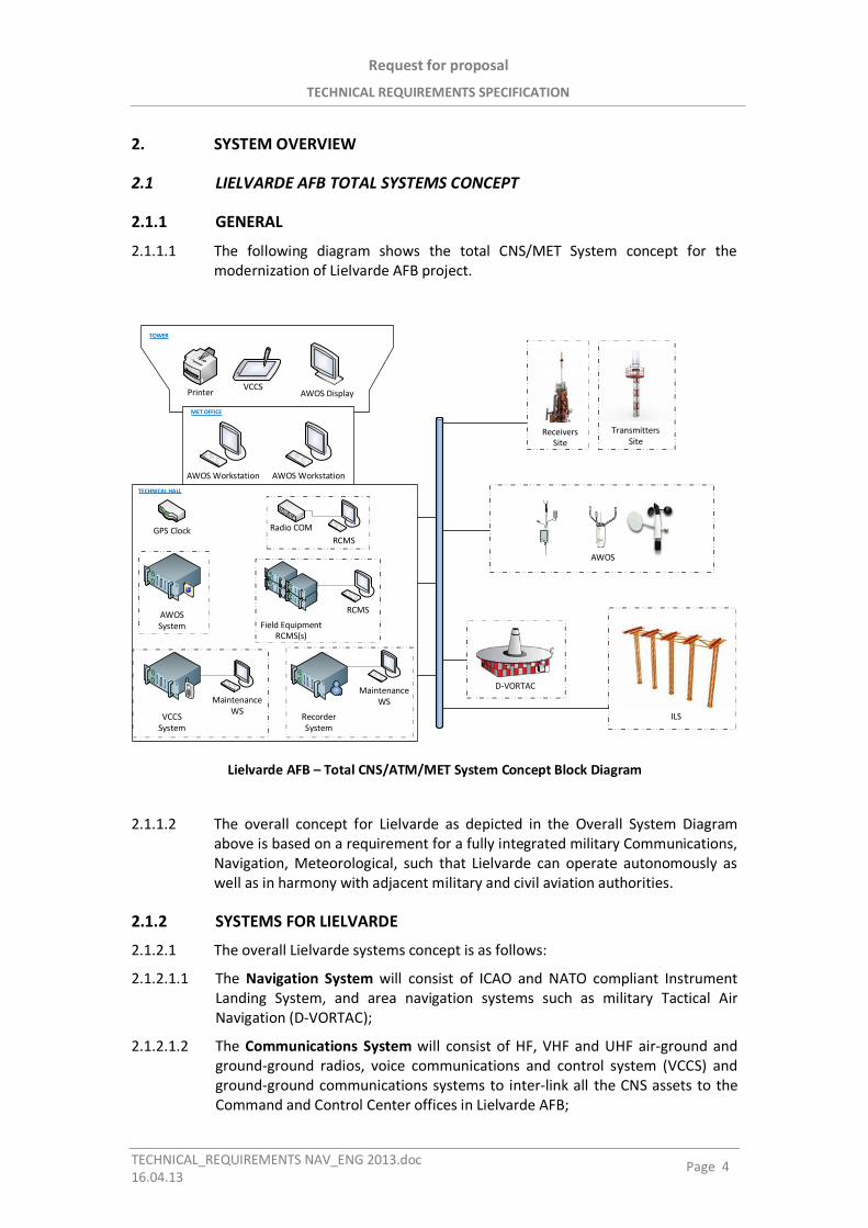
Request for proposal
TECHNICAL REQUIREMENTS SPECIFICATION
TECHNICAL_REQUIREMENTS NAV_ENG 2013.doc16.04.13
Page 4
2. SYSTEM OVERVIEW
2.1 LIELVARDE AFB TOTAL SYSTEMS CONCEPT
2.1.1 GENERAL
2.1.1.1 The following diagram shows the total CNS/MET System concept for themodernization of Lielvarde AFB project.
AWOS Workstation AWOS Workstation
Radio COMRCMS
AWOS DisplayVCCS
Printer
GPS Clock
AWOSSystem
RecorderSystem
VCCSSystem
Field EquipmentRCMS(s)
RCMS
MaintenanceWSMaintenance
WS
TOWER
MET OFFICE
TECHNICAL HALL
AWOS
TransmittersSite
D-VORTAC
ReceiversSite
ILS
Lielvarde AFB – Total CNS/ATM/MET System Concept Block Diagram
2.1.1.2 The overall concept for Lielvarde as depicted in the Overall System Diagramabove is based on a requirement for a fully integrated military Communications,Navigation, Meteorological, such that Lielvarde can operate autonomously aswell as in harmony with adjacent military and civil aviation authorities.
2.1.2 SYSTEMS FOR LIELVARDE
2.1.2.1 The overall Lielvarde systems concept is as follows:
2.1.2.1.1 The Navigation System will consist of ICAO and NATO compliant InstrumentLanding System, and area navigation systems such as military Tactical AirNavigation (D-VORTAC);
2.1.2.1.2 The Communications System will consist of HF, VHF and UHF air-ground andground-ground radios, voice communications and control system (VCCS) andground-ground communications systems to inter-link all the CNS assets to theCommand and Control Center offices in Lielvarde AFB;
Request for proposal
TECHNICAL REQUIREMENTS SPECIFICATION
TECHNICAL_REQUIREMENTS NAV_ENG 2013.doc16.04.13
Page 5
2.1.2.1.3 The Meteorological System will consist of an Automatic Weather ObservationSystem, which will provide current weather observation parameters inautomatic mode, including: wind direction and wind speed, aeronauticalvisibility and Runway Visual Range (RVR), height of the cloud base and cloudamount, some present weather phenomena, atmospheric pressure (QNH, QFE),temperature and relative humidity (dew point temperature). It will allowincorporating of visual observations into automated reports, to provide systemoperator with complete weather observation data set.
2.2 SYSTEM CONCEPT BASIC REQUIREMENTS
2.2.1 NAVIGATION SYSTEM
2.2.1.1 The Lielvarde AFB navigation system will consist of the following subsystems:
2.2.1.1.1 Cat III ILS Localizer;
2.2.1.1.2 Cat III ILS Glidepath;
2.2.1.1.3 DME;
2.2.1.1.4 Tactical Air Navigation (D-VORTAC).
Refer to Attachment 2 for the detailed Requirement Specifications for the ILS System.Refer to Attachment 3 for the detailed Requirement Specifications for the DME System.Refer to Attachment 8 for the detailed Requirement Specifications for the D-VORTAC System.
2.2.2 COMMUNICATIONS SYSTEM
2.2.2.1 The Communication System shall include the following two subsystems:
2.2.2.1.1 Air Traffic Control Tower Communications System
2.2.2.1.2 Communications Information System (CIS)
2.2.2.2 2.2.2.2 Air Traffic Control Tower Communications System
2.2.2.2.1 2.2.2.2.1 The Air Traffic Control Tower (ATC-T) Communications System shallconsist of the following subsystems:
2.2.2.2.1.1 Voice Communication Control System (VCCS);
2.2.2.2.1.2 VHF/UHF Radios (transceivers and receivers);
2.2.2.2.1.3 Voice Logging Recorder System;
2.2.2.2.1.4 GPS Clock System;
2.2.2.2.1.5 Airfield Remote Control and Monitoring System.
The Requirement Specifications for the VCCS are detailed in the Attachment 4
2.2.2.2.2 The following operator workplaces shall be designed and provided:
2.2.2.2.2.1 ATC-T Tower Control
2.2.2.2.2.2 ATC-T Ground Control
2.2.2.2.2.3 ATC-T Auxiliary Position
Request for proposal
TECHNICAL REQUIREMENTS SPECIFICATION
TECHNICAL_REQUIREMENTS NAV_ENG 2013.doc16.04.13
Page 6
2.2.2.2.2.4 Approach Control Operator 1
2.2.2.2.2.5 Approach Control Operator 2 (combined with Supervisor)
2.2.2.2.2.6 Technical Maintenance
2.2.2.2.3 The Bidder shall provide three (3) ATC consoles, two (2) APP consoles and one(1) Technical Maintenance console.
2.2.2.2.4 The design of the consoles shall provide flexible, ergonomic and efficientoperation that eliminate distractions and allow controllers to focus strictly onthe decisions of the moment. For the ATC-T, the consoles shall be designed toprovide the best possible view from a working position towards the outside ofthe airfield.
2.2.2.2.5 The consoles shall be provided with the following features:
2.2.2.2.5.1 Internal 19”rack cabinets for mounting equipment
2.2.2.2.5.2 Aluminum rail systems for mounting displays on flexible arms
2.2.2.2.5.3 Vent panels
2.2.2.2.5.4 Removable panels
2.2.2.2.5.5 Individual power distribution system for each cabinet
2.2.2.2.6 Under table rails shall permit mounting of the following equipment accessories:
2.2.2.2.6.1 Jack panels
2.2.2.2.6.2 Microphones
2.2.2.2.6.3 Handsets
2.2.2.2.6.4 Headset plugs
2.2.2.2.6.5 Flight strip tray holders
The Requirement Specifications for the VHF/UHF Radios are detailed in the Attachment 5
2.2.2.2.7 The following radios are requested for the ATC-T:
2.2.2.2.7.1 Five (5) main/standby VHF-UHF transmitters
2.2.2.2.7.2 Five (5) main/standby VHF-UHF receivers
2.2.2.2.7.3 One (1) emergency VHF-UHF transceiver with independent power backup.
2.2.2.2.8 The requested RF filters, antenna, lightning protection, feeders, antennatowers, and installation materials shall be provided, as a turn-key solution.
2.2.2.2.9 The VHF-UHF transmitters and receivers shall be provided with remote controland maintenance monitoring system and network management system.
2.2.2.2.10 The detailed Requirement Specifications for the Voice Logging RecorderSystem are as follows:
2.2.2.2.10.1 The Voice Logging Recorder shall have the capability to cover all the radio,telephone and inter operator communications. The recording capability shall beredundant.
Request for proposal
TECHNICAL REQUIREMENTS SPECIFICATION
TECHNICAL_REQUIREMENTS NAV_ENG 2013 07.doc 05.07.13
Page 7
2.2.2.2.10.2 The minimum number of channels installed at the VCCS site shall be forty-eight (48). Additional recorders with minimum 16 channels shall be available for other locations upon request.
2.2.2.2.10.3 As a minimum the following features shall be provided:
2.2.2.2.10.3.1 Accurate recording and archiving of calls / radio communications
2.2.2.2.10.3.2 Quick and easy call retrieval
2.2.2.2.10.3.3 Immediate reproduction and availability of the last recorded call
2.2.2.2.10.3.4 Playback without interruption of ongoing recording
2.2.2.2.10.3.5 Reliable archiving of calls on a variety of storage media (HD, DVD, etc.)
2.2.2.2.10.3.6 On-line monitoring
2.2.2.2.10.3.7 Networking capability
2.2.2.2.10.3.8 Expandability
The Requirement Specifications for the Recorder system are detailed in the Attachment 7.
2.2.2.2.11 The detailed Requirement Specifications for the GPS Clock System are as follows:
2.2.2.2.11.1 The GPS Clock System shall be designed and built to meet or exceed all specifications recommended in the NENA (National Emergency Number Association) PSAP (Public Safety Answering Point) Master Clock Standard (NENA-04-002).
2.2.2.2.11.2 GPS Clock System shall allow other equipment designed to meet NENA specifications to be synchronized to the time information as received from the GPS satellites.
2.2.2.2.11.3 The Master Clock shall receive legally traceable time and date information from Global Positioning System satellites and shall supply UTC (Coordinated Universal Time) synchronized data to the ATC-T systems in a variety of forms. A twelve-channel receiver shall be employed, which is capable of tracking up to twelve (12) satellites simultaneously, although reception of only one is required for accurate time data to be output.
2.2.2.2.11.4 The Bidder shall be responsible for the provision of the required interfaces for the following systems:
2.2.2.2.11.4.1 VCCS
2.2.2.2.11.4.2 Voice Logging Recorder
2.2.2.2.11.4.3 RDPS/FDPS
2.2.2.2.11.4.4 Analogue/Digital clocks (minimum 10 interfaces)
2.2.2.2.12 The Requirement Specifications for the Airfield Remote Control and Monitoring System are as follows:
Request for proposal
TECHNICAL REQUIREMENTS SPECIFICATION
TECHNICAL_REQUIREMENTS NAV_ENG 2013.doc16.04.13
Page 8
2.2.2.2.12.1 The RCMS shall provide the remote monitoring and control of the entireCNS/MET system assets at Lielvarde. The Bidder shall propose his concept suchthat the total system can be monitored from a central location.
2.2.2.2.12.2 Both equipment (CNS/MET) and site (Localizer, Glide Path, D-VORTAC, MET)control and maintenance monitoring information shall be included.
2.2.2.2.12.3 The site monitoring shall consist of, but not limited to the following features:
2.2.2.2.12.3.1 Temperature monitoring
2.2.2.2.12.3.2 Smoke alarm monitoring
2.2.2.2.12.3.3 AC power availability
2.2.2.2.12.3.4 Backup generator on
2.2.2.2.12.3.5 Backup generator alarm
2.2.2.2.12.3.6 Backup generator low fuel
2.2.2.2.12.3.7 Open door alarm
2.2.2.2.12.4 The RCMS shall have the capability of central supervision of the operationalstatus of all the ground based aviation system elements used by the facility. Itsmain purpose is to provide the Air Traffic Management operators with acomprehensive graphic representation of the equipment interfacing thesystem’s alarm conditions.
2.2.2.2.12.5 The RCMS shall be specifically customized for the equipment installed at a givenlocation. The Graphical User Interface (GUI) shall make the operation of thesoftware intuitive and interactive.
2.2.2.3 Communications Information System (CIS)
2.2.2.3.1 General Description
2.2.2.3.1.1 The configuration of the Communication Information System is specific for eachtype of operational environment. Basically the CIS shall provide:
2.2.2.3.1.1.1 Continuous communication-information service to the airport personnel;
2.2.2.3.1.1.2 Links to the communication-information networks of the civilian/military aviationinfrastructure;
2.2.2.3.1.1.3 Technical support for the Automated Information System;
2.2.2.3.1.2 The Communication Information System consists of the following subsystems:
2.2.2.3.1.2.1 Communications Information Center (CIC)
2.2.2.3.1.2.2 Automated Information System (AIS)
2.2.2.3.1.2.3 Telephone Centre (PABX network)
2.2.2.3.1.2.4 Ground – Air – Ground Communications, including
Request for proposal
TECHNICAL REQUIREMENTS SPECIFICATION
TECHNICAL_REQUIREMENTS NAV_ENG 2013 07.doc 05.07.13
Page 9
2.2.2.3.1.2.4.1 HF-VHF-UHF Transmitting Center
2.2.2.3.1.2.4.2 HF-VHF-UHF Receiving Center
2.2.2.3.1.2.5 Remote Ground – Air VHF Radio Communications
2.2.2.3.1.2.6 Network equipment (modems, …) to transmit signals from field equipment over redundant Fiber Optic communications backbone (main) and copper communication backbone (standby)
2.2.2.3.1.2.7 Local Area Network (LAN) for connecting the CIC and AIS workstations to public and/or private networks
2.2.2.3.1.2.8 Fiber Optic / Copper Cable / Wireless infrastructure for interconnecting different sites of the airport to the backbone (e.g. Radio Navigation and Surveillance sites to the backbone, Radio Transmitting Center and/or Receiving Center to the backbone, Meteorological System sites to the backbone, local telephone extensions to the PABX, internal interconnections of the systems at control tower)
2.2.2.3.2 Prerequisites
2.2.2.3.2.1 The CIS will be the responsibility of the bidder to describe in detail in his proposal after conducting a mandatory site survey. During the site survey, the Buyer will provide the bidders the opportunity to visit all the locations involved in this project and their roles. The Buyer will advise all the bidders about the dates for the Site Surveys.
The Requirement Specifications for the Site Surveys detailed in the Attachment 1.
2.2.2.3.2.2 The Communications Information Center (CIC) shall be equipped with top of the line Commercial-On-The-Shelf (COTS) workstations, based on specificē operational configuration.
2.2.2.3.2.3 The standard software shall consist exclusively of the following items:
2.2.2.3.2.3.1 MS Windows Professional (latest edition)
2.2.2.3.2.3.2 MS Office Standard (latest edition)
2.2.2.3.2.3.3 Antivirus software (latest edition)
2.2.2.3.2.4 The Automated Information System (AIS) is an infrastructure that provides access to information, and means for information processing, storing, displaying, transferring, and broadcasting. The AIS is structured so that two different types of networks are available, and completely independent:
2.2.2.3.2.4.1 Private Network (Intranet)
2.2.2.3.2.4.2 Public Network (internet)
2.2.2.3.2.5 AIS shall be equipped with top of the line COTS servers, workstations, switching and routing equipment based on specific operational configuration.
2.2.2.3.2.6 The standard software shall consist exclusively of the following items:
Request for proposal
TECHNICAL REQUIREMENTS SPECIFICATION
TECHNICAL_REQUIREMENTS NAV_ENG 2013.doc16.04.13
Page 10
2.2.2.3.2.6.1 MS Windows Professional (latest edition)
2.2.2.3.2.6.2 MS Office Standard (latest edition)
2.2.2.3.2.6.3 Antivirus software (latest edition)
2.2.2.3.2.7 The Telephone Center consists of a PABX network and correspondinginfrastructure.
2.2.2.3.2.8 The PABX specifications shall be based on the end user provided informationregarding the type and number of trunks, type and number of telephone setsfor extensions, type and number of attendants, number of the nodes within thenetwork.
2.2.2.3.2.9 The PABX shall be provided with administration terminal(s) based on thespecific project configuration.
2.2.2.3.2.10 The Ground – Air – Ground Communication System is installed in the HF-VHFUHF Transmitting Center and HF-VHF-UHF Receiving Center.
2.2.2.3.2.11 The following radios are requested for the Transmitting Center:
2.2.2.3.2.11.1 Two (2) HF Transmitters 125W
2.2.2.3.2.11.2 Two (2) HF Transmitters 500W
2.2.2.3.2.11.3 Five (5) VHF-UHF Transmitters
2.2.2.3.2.12 The following radios are requested for the Receiving Center:
2.2.2.3.2.12.1 Four (4) HF Receivers
2.2.2.3.2.12.2 Five (5) VHF-UHF Receivers
2.2.2.3.2.13 The requested RF filters, antennae, lightning protection, feeders, antenatowers, and installation materials shall be provided, as a turn-key solution.
2.2.2.3.2.14 The VHF-UHF transmitters and receivers shall be provided with remote controland maintenance monitoring system and network management system.
2.2.2.3.2.15 The radios shall be operated from the VCCS installed in the ATC-T.
The Requirement Specifications for the VHF/UHF Radios are detailed in the Attachment 5.The Requirement Specifications for the HF Radios are detailed in the Attachment 6.
2.2.2.3.2.16 The Remote Ground – Air Communications (also known as Extended Range VHFRadio System) is subject of separate specifications.
2.2.2.3.2.17 High capacity communications backbone shall provide the requested links tothe communication-information networks of the civilian/military aviationinfrastructure (e.g. other airports, aviation headquarters, Command andControl Center, remote ground – air communication system, Air SovereigntyOperative Center – ASOC, etc.).
2.2.2.3.2.18 A communication backbone to be interconnect all the CNS/MET systemtogether using modern, high capacity data links (fiber optic, microwave, etc.).
Request for proposal
TECHNICAL REQUIREMENTS SPECIFICATION
TECHNICAL_REQUIREMENTS NAV_ENG 2013.doc16.04.13
Page 11
2.2.2.3.2.19 The Bidder shall propose a total communication backbone after conducting adetailed site survey.
2.2.2.3.2.20 The Fiber Optic infrastructure shall be built with sufficient number of SM (SingleMode) fiber cables, installed underground in HDPE pipes (one spare pipe to beincluded for further development).
2.2.2.3.2.21 The precise number of FO cables shall be determined during the site surveys.
2.2.2.3.2.22 The spare FO cables shall be installed.
2.2.2.3.2.23 The fiber optical cable shall be terminated in Optical Distribution Frames (ODF).The distribution to the fiber optic line units shall be made with fiber-optic patchcords.
2.2.2.3.2.24 Each no systems defined above (MW communications, FO terminals andmultiplexors) shall be equipped with remote control terminals, which arenecessary for system administration and remote monitoring.
2.2.2.3.2.25 The Local Area Network (LAN) shall be based on the Ethernet protocol(IEEE 802.X). The network topology shall be star, with number of nodes andports for each node (be defined during the site survey). The central node shallbe assigned to the CIC building.
2.2.2.3.2.26 The links between the nodes shall be provided with fiber optic cables. The fiberoptic infrastructure shall be built with fiber cables, installed underground inHDPE pipes (one spare pipe to be included for further development).
2.2.2.3.2.27 The fiber optical cable shall be terminated in Optical Distribution Frames (ODF).The distribution to the fiber optic line units shall be made with fiber-optic patchcords.
2.2.2.3.2.28 The proper LAN routing equipment shall be used based on the network size.
2.2.2.3.2.29 The Fiber Optic / Copper Cable / Wireless infrastructure consists of the requiredcables, distribution frames, and/or communications equipment.
2.2.2.3.2.30 The technology for the PABX distribution network shall be copper pair cables.
2.2.2.3.2.31 The copper pair cables shall be terminated in Main Distribution Frames (MDF)installed at the entrance in each building. The entrance in the building shall beproperly protected against lightning. The internal distribution to the centralequipment and extension sets shall be made with copper-pair patch cords.
2.2.2.3.2.32 All the other communications between different sites of the airport shall bemade with either fiber optic cables, or wireless transceivers.
2.2.2.3.2.33 In case of fiber optic cables, the fiber optic infrastructure shall be built withfiber cables, installed underground in HDPE pipes (one spare pipe to beincluded for further development). The fiber optical cable shall be terminated inOptical Distribution Frames (ODF). The distribution to the fiber optic equipmentshall be made with fiber-optic patch cords.
2.2.2.3.2.34 In case of wireless communications between sites, the equipment shall consistof spread spectrum transceivers, using the frequency hopping spreadtechnology.
2.2.2.3.2.35 The transceivers shall be capable of uncompressed data rates at high speedover distances of 20 miles or more.
Request for proposal
TECHNICAL REQUIREMENTS SPECIFICATION
TECHNICAL_REQUIREMENTS NAV_ENG 2013.doc16.04.13
Page 12
2.2.2.3.2.36 The transceivers shall be able to operate point to point or point to multipoint,mode selectable using an asynchronous terminal program. Up to two repeatersmay be used to extend the range by programming the transceiver to operate asa store and forward unit, in order to reach distances of 60 miles, or more.
Request for proposal
TECHNICAL REQUIREMENTS SPECIFICATION
TECHNICAL_REQUIREMENTS NAV_ENG 2013.doc16.04.13
Page 13
3. SERVICES
3.1 INSTALLATIONS AND TRANSITION OPERATIONAL IMPACT
3.1.1 General
3.1.1.1 Within about 2(two) weeks of the issuing of the Tender, the ContractingAuthority shall hold a Bidder’s Meeting in Latvia at which time the Buyer shallbrief the Bidder on the LAF Communication concept.
3.1.1.2 Visits of their approximate locations all the relevant LAF CNS assets associatedthe Lielvarde project will be facilitated, where the Bidders can conduct detailedsite survey.
3.1.1.3 The Bidders shall submit as a part of their proposals, detailed communicationsystem to interconnect all the CNS assets within the AirForce Base and to withother agencies.
3.1.1.4 The Bidder shall perform an in-depth Site Survey within thirty days of Contractaward. Detail drawings along with engineering reports of each site will be givento the Buyer within 60 days.
3.1.1.5 The Bidder shall propose a Detailed Site Installation Plan that will identifydetailed equipment configuration for each system and describe in details allareas of work needed to fully install the total system and recommend transitionhardware placement and configuration.
Refer to Attachment 1 for the detailed Requirement Specifications for the Site Surveys.
3.2 TRAINING
3.2.1 Introduction
3.2.1.1 The Bidder shall propose a comprehensive training package as described below:
3.2.1.1.1 System Maintenance (hardware/software) training for 10 electronic techniciansfor Navigation and Communication systems and associated subsystems.
3.2.1.1.2 Supervisory training for 10 senior supervisory staff.
Request for proposal
TECHNICAL REQUIREMENTS SPECIFICATION
TECHNICAL_REQUIREMENTS NAV_ENG 2013.doc16.04.13
Page 14
3.2.1.2 Training documentation requirements are included here.
3.2.1.3 Detailed training programs for the technical personnel shall be negotiated
3.2.2 General
3.2.2.1 Syllabus, lesson’s plans and lecture notes (handouts) shall be provided for theeach training course.
3.2.2.2 The Training shall be provided separately for every system/equipment, if it wasnot specially defined.
3.2.2.3 To ensure efficient training, it is essential that a high standard ofdocumentation is provided.
3.2.2.4 The documentation shall be in the English (or Latvian) language, provide allinformation required, and be presented in a clear, and concise format.
3.2.2.5 All training courses shall:
3.2.2.5.1 be conducted in the English (or Latvian) language;
3.2.2.5.2 involve theoretical and practical training;
3.2.2.5.3 provide simulation of faults;
3.2.2.5.4 use documentation provided for the each system.
3.2.2.6 After training course the Bidder shall give a document (Certificate) whichconfirms training completion.
3.2.3 Training Documentation
3.2.3.1 In case final training documentation is not available at the beginning of thetraining, preliminary versions of both the information and instructionaldocuments shall be provided.
3.2.3.2 Descriptions and detailed data included in the documentation shall comply withthe characteristics of the delivered equipment as closely as possible.
3.2.3.3 Any advertising or sales promoting material shall not be included in the trainingmaterial.
3.2.3.4 The Bidder shall:
3.2.3.4.1 deliver to the Buyer detailed course programs and documentation at least 1month before the beginning of the course;
3.2.3.4.2 provide each participant with a complete set of course material at thebeginning of the course;
3.2.3.4.3 at the end of the course deliver a complete set of instructor's training material(presentations, transparences, films, video tapes etc.) to the Buyer.
Request for proposal
TECHNICAL REQUIREMENTS SPECIFICATION
TECHNICAL_REQUIREMENTS NAV_ENG 2013.doc16.04.13
Page 15
3.2.4 Training Facilities and Equipment
3.2.4.1 When training takes place at the Bidder´s factory/training center suitableclassrooms and laboratory facilities shall be provided.
3.2.4.2 Students shall have access to rest areas, and the Bidder shall arrange foraccommodation, transportation, first aid service, etc.
3.2.4.3 All test equipment used under training shall be of the same kind as Contracted.
3.2.4.4 Maintenance of training test equipment is the Bidder´s responsibility.
3.2.5 Training of Operational Personnel
3.2.5.1 Under the Contract, system-related training for operational personnel shall beprovided.
3.2.5.2 The Bidder shall provide the training after the project has been defined anddocumented in the Product Specification and prior to, but as close as possibleto the FAT starting date
3.2.5.3 The training course shall include:
3.2.5.3.1 general course on system hardware;
3.2.5.3.2 detailed course on rules of the system operating;
3.2.5.3.3 documentation on the system operation.
3.2.5.4 At the completion of the course each participant shall have:
3.2.5.4.1 clear overview of the system;
3.2.5.4.2 knowledge of the functional design and operation of the system;
3.2.5.4.3 detailed knowledge of operational functions, input functions and their results,etc. enabling to operate the work station equipment in accordance with thedesigner's requirements.
3.2.5.5 This shall include to:
3.2.5.5.1 carry out all the functional operations envisaged by the specifications;
3.2.5.5.2 select any configuration of the system and to be able to accomplishreconfiguration of the system;
3.2.5.5.3 to operate the workstation equipment in accordance with the designer'srequirements.
3.2.6 Training of Maintenance Personnel
3.2.6.1 Under the Contract, system-related training shall be provided for maintenancepersonnel and system engineers.
3.2.6.2 The Bidder shall provide the training after the project has been defined anddocumented in the Product Specification and prior to, but as close as possibleto the FAT starting date
3.2.6.3 The training course shall include:
3.2.6.3.1 detailed system hardware course;
3.2.6.3.2 system operating course;
Request for proposal
TECHNICAL REQUIREMENTS SPECIFICATION
TECHNICAL_REQUIREMENTS NAV_ENG 2013.doc16.04.13
Page 16
3.2.6.3.3 installation, maintenance and technical parameter changes.
3.2.6.4 At the completion of the course each participant shall have:
3.2.6.4.1 clear overview of the complete system;
3.2.6.4.2 a sound understanding of individual sub-systems;
3.2.6.4.3 knowledge of the functional design and operation of the system down to boardlevel;
3.2.6.4.4 detailed knowledge of operational functions, input functions and their results,etc. enabling the operation of all sub-systems and work station equipment;
3.2.6.4.5 detailed knowledge of how to perform preventive and corrective maintenance.
3.2.6.5 This shall include to:
3.2.6.5.1 check performance parameters;
3.2.6.5.2 interpret fault conditions;
3.2.6.5.3 select and apply maintenance aids such as fault finding procedures, testprograms, control and monitoring test equipment;
3.2.6.5.4 carry out adjustments allowable for maintenance personnel;
3.2.6.5.5 perform necessary restoration of service.
3.2.7 Proposal from the Bidder
3.2.7.1 The Bidder shall, based on the guidelines given above, compose an adaptedtechnical training course program.
3.2.7.2 Each course shall have a description, duration, location and an allowedmaximum number of participants.
3.2.7.3 The Bidder shall state the price for each of the courses in his proposal whichshall also form a part of the Contract.
3.2.7.4 When training takes place at the Contractor´s factory/training center travelcost, accommodation and daily expenses for trainees shall be provided by theContractor.
Request for proposal
TECHNICAL REQUIREMENTS SPECIFICATION
TECHNICAL_REQUIREMENTS NAV_ENG 2013.doc16.04.13
Page 17
3.3 QUALITY ASSURANCE
3.3.1 General Requirements
3.3.1.1 The Bidder shall provide its Quality Assurance Plan to the Buyer. The QAP shallconform to the following guidelines
3.3.1.2 Quality System Requirements
3.3.1.2.1 To prevent nonconformity at all stages of the project, Bidder shall haveestablished a quality system in accordance with the requirements in thedocument: STANDARD ISO 9000 SERIES (the latest version available, but notlower than ISO9001:2008).
3.3.1.2.2 If the Bidder uses a standard other than stated above compliance with it shallbe stated in the compliance table and a correspondence with the ISO 9000series standards shall be stated.
3.3.1.2.3 All of the offered equipment shall be produced in accordance with theEuropean Union Directives to obtain the CE symbol (including the standards forelectromagnetic compliance (EMC) as well as the safety regulations, whichensure the protection of personnel and equipment).
3.3.2 Quality Control and Verification
3.3.2.1 Introduction
3.3.2.1.1 Although the objective of the prescribed quality system is to preventnonconformity to materialize, verification shall be an important activity.
3.3.2.1.2 The verification activities shall be an on-going process that extends from theconception of the system up to and including its acceptance by the Buyer.
3.3.2.1.3 The verification process shall include design reviews, inspections, and relevanttests. As the realization of the system progresses, tests shall be performed atincreasingly higher levels of items. Test procedures shall be worked out forassemblies, units, sub-systems and other equipment.
3.3.2.2 Design Reviews
3.3.2.2.1 Design reviews shall be held at appropriate points in the design anddevelopment phase in order to verify compliance with the requirements in theSpecification.
3.3.2.2.2 Completion of the design reviews shall result in the release of preliminaryacceptance test procedures.
3.3.2.2.3 Design reviews shall be performed by the Bidders own organization.
3.3.2.2.4 Preliminary acceptance test procedures shall be made available to the Buyer.
3.3.2.3 Quality Inspection
3.3.2.3.1 The Bidder shall have the full responsibility for a proper and thoroughsupervision of the manufacturing process.
Request for proposal
TECHNICAL REQUIREMENTS SPECIFICATION
TECHNICAL_REQUIREMENTS NAV_ENG 2013.doc16.04.13
Page 18
3.3.2.3.2 The Bidder shall have full responsibility for quality of the equipment under theContract even if the Buyer has made use of his right to verify the manufacturingprocess through inspection activities.
3.3.2.3.3 The Buyer's representative shall be given complete insight in the Bidder's andany Sub-Supplier's manufacturing and QA activities.
3.3.2.3.4 Should the Buyer's representative so wish, he shall be entitled to carry out hisown verification tests and reviews. In such cases he shall be given full assistancefrom the Bidder's staff.
3.3.2.3.5 All approvals shall be in written form and signed by the Buyer's ProjectManager or his authorized representative.
3.3.2.4 Testing
3.3.2.4.1 A formal stability verification test before commissioning of the contractedequipment is part of the Buyer's requirements.
3.3.2.4.2 The objective of the Buyer's testing requirements is a full verification that theequipment, when completed and installed on site, meets the contractualspecifications, as laid down in the Specification.
3.3.2.4.3 Tests are divided into two categories:
3.3.2.4.3.1 production tests, which shall be performed by the Bidder in order to verifycompliance to specifications of items at lower levels;
3.3.2.4.3.2 acceptance tests, which shall be performed by the Bidder in order to verifycompliance to specifications of items at lower levels.
3.3.2.4.4 Acceptance tests shall be performed on items at sub-system level and higher, inorder to demonstrate that the item concerned meets the specified functionalperformance.
3.3.2.4.5 The Buyer shall be prepared to accept such tests being applied to units if theperformance or capabilities of such units cannot be demonstrated properlyunder higher level tests, or if testing of units will give a better verification ofcompliance.
3.3.2.4.6 Acceptance tests are of important significance for the Buyer. Every acceptancetest shall be performed in the presence of the Buyer, who will sign theacceptance documentation upon successful completion of the tests.
3.3.2.4.7 All Acceptance tests shall be further divided into 2 categories:
3.3.2.4.7.1 Factory Acceptance Tests (FAT)
3.3.2.4.7.2 Site Acceptance Tests (SAT).
Request for proposal
TECHNICAL REQUIREMENTS SPECIFICATION
TECHNICAL_REQUIREMENTS NAV_ENG 2013.doc16.04.13
Page 19
3.4 ACCEPTANCE TESTING
3.4.1 Factory Acceptance Test (FAT)
3.4.1.1 Before the actual Factory Acceptance test a full-scale internal preliminary testshall be arranged according to the specification. The Buyer reserves the right toattend this test as an observer. The Bidder shall notice in due time the start ofthis preliminary test, however not later than one month in advance.
3.4.1.2 FAT is a test in the Bidder's facilities, which is conducted in accordance with theagreed FAT specification.
3.4.1.3 The Buyer shall be entitled to witness the test and shall be notified about theFAT in due time (at least 3 months in advance). Upon successful completion ofthe FAT the Buyer will sign the test protocol.
3.4.2 Site Acceptance Test (SAT)
3.4.2.1 A test at the Buyer's premises which is conducted in accordance with theagreed SAT specification. The Buyer shall witness the test and will sign the testprotocol upon successful completion of the test.
3.4.3 Factory Acceptance Test (FAT)
3.4.3.1 A selection of the required documentation shall be approved by the Buyer, asindicated below. The following documentation is relevant for the FAT:
3.4.3.1.1 TEST PLAN, which shall contain the general conditions and definitions, a testwork flow which defines the test sequence and identifies the related testspecifications and test procedures, and a general description of the tests. TheTest Plan shall be worked out by the Bidder and shall be made available for theBuyer for review and approval latest three months prior to the expected startof the FAT.
3.4.3.1.2 TEST SPECIFICATION, which shall include detailed descriptions of the varioustests and also include criteria for acceptance/rejection, conditions andinterfaces. In addition, requirements for test provisions such as test tools, testequipment and test software shall be included. The Test Specification shall beworked out by the Bidder and sent, together with the Test Plan, to the Buyerfor review latest two months prior to the expected start of the FAT.
3.4.3.1.3 CERTIFICATION RECORD, which shall indicate the type of test, the items testedand test result, including possible remarks. After completion of eachacceptance test an equipment certification record shall be filled in. Remarksmay include agreed deviations from the test procedure. The CertificationRecord shall be the formal document for recording of approval of the relevanttest. Both the Employer and the Supplier shall sign the Certification Record.
3.4.3.1.4 LIST OF DELIVERY. The list of delivery shall contain information about theconfiguration of the equipment down to sub-assembly level.
Request for proposal
TECHNICAL REQUIREMENTS SPECIFICATION
TECHNICAL_REQUIREMENTS NAV_ENG 2013.doc16.04.13
Page 20
3.4.3.2 The Bidder shall accomplish the agreed Factory Acceptance Test (FAT) programin the presence of the Buyer's appointed representatives.
3.4.3.3 The FAT shall be run to verify whether the equipment, before delivery, satisfiesthe functional requirements and technical specifications defined in theContract.
3.4.3.4 It is accepted that factory acceptance tests are performed under theenvironmental conditions that prevail in the Bidder's test department at thetime of the test.
3.4.3.5 The FAT shall be performed following the Test Plan, successively checking theitems for compliance with the Test Specification.
3.4.3.6 The Bidder shall provide all instruments, equipment, materials, facilities andservices required for an appropriate realization of the FAT.
3.4.3.7 During the FAT the Certification Record shall be completed. The configuration ofthe equipment during the FAT shall correspond to the one requested by theBuyer.
3.4.3.8 Should problems arise during the FAT or should the FAT test results be deemedunsatisfactory in any major way by the Buyer, the problems shall be correctedand the status shall be mutually verified and agreed. The Bidder shall take fulleconomic responsibility for any required re-testing program.
3.4.3.9 The following set of documentation shall be handed over to the Buyer asevidence of a successfully completed FAT:
3.4.3.9.1 the Certification Record, signed by the Buyer or their representatives uponcompletion of the test,
3.4.3.9.2 the List of Delivery
3.4.3.10 These Factory Acceptance Test documents, properly signed by the Bidder andthe Buyer, shall imply that the equipment is accepted by the Buyer for deliveryto the site.
3.4.4 Site Acceptance Test (SAT)
3.4.4.1 A selection of the required documentation shall be approved by the Buyer, asindicated below. Upon approval by the Buyer these documents shall be bindingon both parties. The following documentation is relevant for the SAT:
3.4.4.1.1 TEST PLAN, which shall contain the general conditions and definitions, a testwork flow which defines the test sequence and identifies the related testspecifications and test procedures, and a general description of the tests. TheTest Plan shall be worked out by the Bidder and shall be made available for theBuyer for review and approval latest three month prior to the expected start ofthe SAT or after completion of the FAT, whichever is the latest.
3.4.4.1.2 TEST SPECIFICATION, which shall include detailed descriptions of the varioustests and also include criteria for acceptance/rejection, conditions andinterfaces. In addition, requirements for test provisions such as test tools, testequipment and test software shall be included. The Test Specification shall beworked out by the Bidder and sent, together with the Test Plan, to the Buyerfor review latest two months prior to the expected start of the SAT or aftercompletion of the FAT, whichever is the latest.
Request for proposal
TECHNICAL REQUIREMENTS SPECIFICATION
TECHNICAL_REQUIREMENTS NAV_ENG 2013.doc16.04.13
Page 21
3.4.4.1.3 CERTIFICATION RECORD, which shall indicate the type of test, the item testedand the test result, including possible remarks. After completion of eachacceptance test, an equipment certification record shall be filled in. Remarksmay include agreed deviations from the test procedure. The CertificationRecord shall be the formal document for recording the approval of the relevanttest. Both the Buyer and the Bidder shall sign the Certification Record.
3.4.4.1.4 LIST OF DELIVERY. The list of delivery shall contain information about theconfiguration of the equipment down to sub-assembly level.
3.4.4.2 The objective of the Site Acceptance Test is to confirm that the system, afterinstallation on site, is compliant with all the specifications.
3.4.4.3 A complete Site Acceptance Test shall include verification of all items deliveredin accordance with the Bidder including training and documentation
3.4.4.4 The Site Acceptance Tests will be performed under the environmentalconditions that will exist under normal operation for the equipment contracted.
3.4.4.5 It shall be the responsibility of the Bidder to provide required documentation,test equipment, measuring instruments, tools etc. prior to the start of the SAT.
3.4.4.6 The SAT shall be performed following the Test Plan and the Test Specification.
3.4.4.7 Flight Inspection (Check) for navigation systems (ILS and D-VORTAC) shall beconsidered as a part of SAT and shall be the responsibility of Bidder to ordernecessary Installation and Commissioning Flight Check from neutral Provider.
3.4.4.8 Equipment under SAT shall consist of the complete system in accordance withthe Contract.
3.4.4.9 The final phase of the SAT shall include a long term STABILITY TEST, lasting forminimum 30 days, during which the system shall run under continuous relevantoperation without any signs of anomalous function. The procedures of thestability test and the criteria and conditions to be granted acceptance shall bemutually agreed.
3.4.4.10 The configuration of the equipment, as it is during the SAT shall be laid down inthe List of Delivery.
3.4.4.11 Should problems arise during the SAT or should the SAT test results be deemedunsatisfactory in any major way by the Buyer, the problems shall be correctedand the status shall be mutually verified and agreed.
3.4.4.12 The following set of documentation shall be handed over to the Buyer asevidence of a successfully completed SAT:
3.4.4.12.1 the certification record, signed by the Buyer or their representative uponcompletion of the test,
3.4.4.12.2 the list of delivery.

Request for proposal
TECHNICAL REQUIREMENTS SPECIFICATION
TECHNICAL_REQUIREMENTS NAV_ENG 2013 10 17.10.13
Page 22
3.5 WARRANTY
3.5.1 General
3.5.1.1 The warranty period for the entire system shall commence after Buyer acceptance and last for 2 year.
3.5.1.2 The Bidder shall be responsible to provide system maintenance support during the warranty period.
3.5.1.3 The Bidder shall propose a maintenance concept for the on-going management of the installed systems after acceptance.
3.5.1.4 A fully covered contractor maintenance proposal shall be provided within 4 months after contract award.
Request for proposal
TECHNICAL REQUIREMENTS SPECIFICATION
TECHNICAL_REQUIREMENTS NAV_ENG 2013.doc16.04.13
Page 23
3.6 SPARES
3.6.1 Initial Spares
3.6.1.1 Initial spare parts shall be provided by the Bidder and shall be sufficient formaintaining all hardware items for a three-year period, including the warrantyperiod.
3.6.1.2 The spare parts will be for all delivered systems and equipment including testand ancillary equipment.
3.6.2 Sparing Level
3.6.2.1 The recommended sparing level shall be based upon the Bidder’s reliability datafor the system being provided and reflect the reliability expected in the Buyer’soperational environment.
3.6.2.2 The Bidder shall provide these reliability data as part of the response to thistender.
3.6.3 Description of Spares
3.6.3.1 Spares will consist of LRM and LRU spares, as well as consumable itemsrequired for system operation, including, but not limited to, fuses, lamps,printer supplies, and specialized print medium.
3.6.4 Spares List
3.6.4.1 The recommended spares list shall be fully itemized and individually priced andshall be included as part of the tender documentation.
3.6.5 Guarantees
3.6.5.1 The Bidder shall guarantee the availability of all spare parts and modules for theCOTS equipment offered for a period of at least 5 years.
3.6.5.2 The Bidder shall guarantee the availability of all spare parts and modules for thespecial equipment offered for a period of at least 10 years.
3.6.5.3 The equipment vendor shall, for a period of 20 years, monitor the availability ofrepair parts, and shall provide the Buyer at least 3 months’ notice in writing ofsupplier(s) intending to terminate their manufacture and the date by which theBuyer may place orders for the final production run.
3.7 DOCUMENTATION
3.7.1 General
3.7.1.1 The documentation shall make it possible to the Buyer to:
3.7.1.1.1 Perform fault detection and repairing on a routine basis
3.7.1.1.2 Estimate how functions in hardware may be changed and completed withouttedious studying of details
Request for proposal
TECHNICAL REQUIREMENTS SPECIFICATION
TECHNICAL_REQUIREMENTS NAV_ENG 2013.doc16.04.13
Page 24
3.7.1.2 The design of documentation shall be such that the Buyer's staff in appropriatelength of time and by themselves shall be able to:
3.7.1.2.1 Reach good knowledge of principles of hardware structure and way ofoperation
3.7.1.2.2 Understand how certain hardware parts cooperate to perform certain functions
3.7.1.2.3 Understand interfaces between different units
3.7.1.2.4 Locate erroneous units and make corrections
3.7.1.3 The system documentation shall include complete technical manuals for eachequipment and part of the system consisting at least the System descriptionand Software description
3.7.1.4 Documentation data must be recorded to the CD/DVD media in commonsoftware like (Excel, Word, Acrobat, Auto-Cad, etc.)
3.7.1.5 The Buyer shall have the right up to mutually agreed level to copy and usedelivered documentation.
3.7.1.6 To assist any further modification and use of the documentation it should beavailable also in electronic data form with suitable media.
3.7.1.7 The Bidder shall provide 3 complete sets of system operations and maintenancemanuals for each subsystem
3.7.2 Hardware documentation
The documentation of hardware shall include:
3.7.2.1 Technical manuals:
3.7.2.1.1 General description
3.7.2.1.2 Technical functions
3.7.2.1.3 Mechanical lay-out
3.7.2.1.4 Maintenance instructions
3.7.2.2 Technical data:
3.7.2.2.1 Parts lists (List of used components with serial numbers)
3.7.2.2.2 Communication settings
3.7.2.2.3 Logic and circuit schematics
3.7.2.2.4 Cabling documentation
3.7.2.3 Installation description:
3.7.2.3.1 Distribution plan
3.7.2.3.2 Cable runs
3.7.2.3.3 Interconnection schematics
Request for proposal
TECHNICAL REQUIREMENTS SPECIFICATION
TECHNICAL_REQUIREMENTS NAV_ENG 2013.doc16.04.13
Page 25
3.7.3 Software documentation
3.7.3.1 The documentation shall make it possible for the Buyer to:
3.7.3.1.1 To find out easily version of software
3.7.3.1.2 Perform fault detection and repairing on a routine basis
3.7.3.1.3 Estimate how functions and software may be changed and completed withouttedious studying of the details and making excessive summaries
3.7.3.2 The design of the documentation shall be such that the members of the Buyer'sstaff in appropriate length of time and by themselves shall be able to:
3.7.3.2.1 Reach good knowledge of the principles of software structures and way ofoperation
3.7.3.2.2 Understand how certain software parts cooperate to perform certain functions
3.7.3.2.3 Understand interfaces between different programs and interfaces betweenhardware and software
3.7.3.2.4 Understand how every single program and program module operate
3.7.3.2.5 Understand organization and meaning of data in the system
3.7.3.2.6 Understand all error signals from the system
3.7.3.2.7 Estimate computer capacity, how it is used and determine reserve capacity
3.7.3.3 The documentation of the software shall at least include:
3.7.3.3.1 An overall system description
3.7.3.3.2 All necessary manuals to meet the requirements of software production andmaintenance
3.7.3.3.3 The complete linked system, including the bootstrap loader for initial systemloading, stored on media acceptable to the Buyer.
3.7.3.3.4 It shall be possible to restore the system from scratch using the providedinstallation media.
3.7.3.3.5 System and workstation images on a CD/DVD media
3.7.4 Miscellaneous documentation
3.7.4.1 Test procedure and test report documentation for Factory Acceptance Test.
3.7.4.2 Test procedure and test report documentation for Site Acceptance Test
3.7.4.3 Training documentation
3.7.4.4 Reliability analysis
3.7.4.5 Maintenance plan
3.7.4.6 Risk analysis
Request for proposal
TECHNICAL REQUIREMENTS SPECIFICATION
TECHNICAL_REQUIREMENTS NAV_ENG 2013.doc16.04.13
Page 26
3.8 HARDWARE AND SOFTWARE REQUIREMENTSIn case if it is not specially defined in the current document or its attachments,the Bidder should provide the hardware and software, which fulfils thefollowing requirements:
3.8.1 Software Requirements
3.8.1.1 System-level software for servers shall be one of the commercially availablemulti-tasking, multi-user Operating System (OS). One of the OS UNIX™ versionsor their clones (such as Linux), which supports Intel® hardware platform arepreferred.
3.8.1.2 System-level software for Working Positions shall be one of the commerciallyavailable multi-tasking, multi-user Operating System (OS). One of the OS UNIX™versions or their clones (such as Linux), which supports Intel® hardwareplatform are preferred, however Microsoft® Windows™ 7 or later version willbe considered as a suitable OS
3.8.1.3 Off-the-shelf (COTS) database software shall be provided for servers.
3.8.1.4 System and application software shall support dual server architecture andallow automatic and manual switching of the primary/standby server, in case offailure or for the maintenance purposes.
3.8.2 Hardware Requirements
3.8.2.1 Off-the-shelf (COTS) equipment shall be provided for server and workstationsequipment. Solutions, based on Intel® Pentium™ platform (Dell, HP, FUJITSU)are preferred.
3.8.2.2 The server and communication equipment should reside in standard 19” rack(the dimension should be at least: 2000mm height, 600mm width, 1000mmdepth). Rack shall be equipped with rack-mounted console including LCDmonitor, keyboard and mouse.
3.8.2.3 All the server equipment, including computers, display, keyboard, etc., shouldbe rack-mounted.
3.8.2.4 In case of several servers, it shall be necessary to provide an Off-the-shelf(COTS) KVM switch with correspondent number of KVM ports.
3.8.2.5 Each server should have the configuration, not worse that:
3.8.2.5.1 Processor: X86 architecture with 4 cores (64 bit support). 2 processors with 8cores total. Min. 185 point benchmark by SPECint_rate2006 test(http://www.spec.org);
3.8.2.5.2 Memory: At least 32 GB DDR3 with Advanced ECC with possibility to extend till128 Gb;
3.8.2.5.3 HDD: 4x300 GB 15000 RPM, Hot Swap(SAS or SCSI interface);
3.8.2.5.4 Optical equipment: CD-RW/DVD-RW drive (EIDE or SCSI interface);
3.8.2.5.5 Network Interface Card(s), Base-T Dual Gigabit Ethernet with RJ-45 socket;
3.8.2.5.6 Rack-mount (19”) case with the redundant power supply of sufficientcharacteristics and appropriate cooling;
Request for proposal
TECHNICAL REQUIREMENTS SPECIFICATION
TECHNICAL_REQUIREMENTS NAV_ENG 2013.doc16.04.13
Page 27
3.8.2.5.7 USB 2.0: 2 USB 2.0
3.8.2.5.8 Video card, which supports resolution of 1280x1024,
3.8.2.5.9 17” High Resolution LCD display;
3.8.2.5.10 Additional components, like multi-port serial interfaces, magneto optical ortape
3.8.2.5.11 storage device for long-term data archiving or DVD/CD-writer, modems, etc.,shall be provided.
3.8.2.6 The servers shall be provided with embedded redundancy functionalityincluding dual power supplies, mirrored hard drives (RAID 0/1/5), etc.
3.8.2.7 Each CWP should have the configuration, not worse that:
3.8.2.7.1 Processor: Processor: X86 architecture with min. 2550 point benchmark byPassMark CPU test (http://www.cpubenchmark.net) with possibility extend for2 processors;
3.8.2.7.2 Memory: At least 4 GB DDR3 expandable till 8 GB;
3.8.2.7.3 HDD: 160 GB (PATA/SATA or SCSI interface);
3.8.2.7.4 CD/DVD drive (PATA/SATA or SCSI interface);
3.8.2.7.5 Network Interface Card(s), Ethernet 10/100/1000 Base-T with RJ-45 socket;
3.8.2.7.6 Video card, which supports resolution of 1920x1080 min (for Tower positions2K x 2K);
3.8.2.7.7 24” LCD display (for Tower positions with daylight settings). The other displayscould have another parameters, but not worse than described above
3.8.2.7.8 Additional components, like multi-port serial interfaces, magneto opticalstorage device for long-term data archiving or DVD/CD-writer, modems, etc.,shall be provided as necessary.
3.8.2.8 The workstations shall be provided with mirrored hard drives (RAID 0/1/5)
3.8.2.9 Every workstation shall be equipped with all necessary power cables,communication cables, input\output devices (mouse/trackball, keyboard, etc.).
3.8.2.10 Sufficient number of short-range modems shall be provided for the systems,which requires serial asynchronous connection.
3.8.2.11 The system should be equipped with one or more network packet switches toallow network communication between system components (servers,workstations) and external equipment.
3.8.2.12 Network switches should allow connection of the equipment by means of1000BaseT Category 6 twisted pair cabling or higher.
3.8.2.13 The system should be equipped with number of printers. It should be networkor local printers depending on the configuration.
3.8.2.14 The laser printers are preferable, however in special cases and for specialpurposes the matrix printers will be considered as suitable solution.

Request for proposal
TECHNICAL REQUIREMENTS SPECIFICATION
TECHNICAL_REQUIREMENTS NAV_ENG 2013.doc16.04.13
Page 28
3.9 CIVIL WORKS
3.9.1 General Requirements
3.9.1.1 The Bidder shall evaluate existing situation at the Lielvarde AFB as well as theworks performed during the reconstruction and review all available information(design, surveys of performed works etc.).
3.9.1.2 If the information is insufficient the Bidder shall obtain additional data that isrequired for installation of proposed equipment (topographical survey,geological survey etc.).
3.9.1.3 The Bidder shall provide all the required construction works for installation ofproposed equipment including construction of foundations, access roads,communication networks and providing the water drainage.
3.9.1.4 The Bidder shall provide development of appropriate design to perform the civilworks.
3.10 MAINTENANCE REQUIREMENTS
3.10.1 General
3.10.1.1 The ILS/DME and DVORTAC systems shall include maintenance features, whichprovide system operators and maintenance personnel with full informationabout system status all the time. Moreover, to satisfy availability requirements,outage time shall be minimised by functions and facilities, which enable rapiddiagnosis of malfunction, identification and replacement of the failed unit.
3.10.1.2 The Bidder shall present complete set of maintenance documentation includelist of all required maintenance procedures and all measurement equipment’sand tools required to carry out those maintenance.
3.10.1.3 The maintenance philosophy and planned operations herein after are the basisfor the Contract, but however, if the Bidder thinks he can evaluate and state acorresponding or better solution, he shall do so.
3.10.1.4 Following items are considered:
system design considerations;
maintenance concept;
system management;
preventive maintenance;
corrective maintenance;
maintenance supports;
technical monitoring and control.
3.10.2 System design Consideration
3.10.2.1 Design considerations shall include at least, but not be limited to:
maximum reliability of equipment;
Request for proposal
TECHNICAL REQUIREMENTS SPECIFICATION
TECHNICAL_REQUIREMENTS NAV_ENG 2013.doc16.04.13
Page 29
maximum availability of equipment;
redundancy of equipment and/or modules.
3.10.2.2 Features that will allow internal on-line diagnostics for isolating failed modulesand effect system restoration by reconfiguring the system by using redundantmodules.
3.10.2.3 Modular design that permits an easy access to and simple replacement ofdefective modules and subassemblies.
3.10.2.4 Standardisation of modules or units, to the extent practicable, to reduce lifecycle costs including training, spare-keeping, etc.
3.10.2.5 The maintenance design features shall include on-line and off-line diagnostics,which together with built-in test equipment, test points and fault indicators,should quickly detect the existence of pinpoint and the source of a failure.
3.10.2.6 Diagnostics, status information and control of system are required to behandled via terminals, which should be located in the Technical Monitoring &Control (TMC) facility.
3.10.2.7 Special tools to remove, repair, replace and adjust units shall be minimum forusing.
3.10.2.8 All Lowest Replaceable Modules (LRM), subassemblies, parts, test points andterminals shall be readily accessible for adjustment and maintenance. Each unitshall be so mounted as to permit its replacement without the partial orcomplete removal of any other.
3.10.2.9 The Bidders shall describe the method of the main LRM replacement. The hotswap of LRM is preferable.
3.10.2.10 Adjustments and routine servicing such as lubrication, screwdriver adjustments,etc., for rack mounted equipment, shall be possible without removing theequipment from the rack in which it is installed.
3.10.2.11 The hardware shall be designed to minimise the effects of individual partfailures. The design shall prevent the propagation of the effects of an error.
3.10.2.12 The Bidders shall present to the Buyer the equipment failure detection ratioand MTBF for DVORTAC, ILS, DME and it components.
3.10.3 Maintenance Operation
3.10.3.1 General
3.10.3.1.1 The maintenance operation is based on the premise of a highly reliablehardware design with a reasonable amount of redundancy at the system level.Therefore necessary design features to keep maintenance requirements to aminimum shall be incorporated.
3.10.3.1.2 Maintenance activities are classified into five items:
system management;
certification;
preventive maintenance;
corrective maintenance;
Request for proposal
TECHNICAL REQUIREMENTS SPECIFICATION
TECHNICAL_REQUIREMENTS NAV_ENG 2013.doc16.04.13
Page 30
technical support.
3.10.3.1.3 The Bidder shall present to the Buyer the list off all measurement devices,accessories, tools and etc., required for site survey, installation, commissioningand all kind of maintenance. All items of this list shall be included to offer asseparate items, but the list of units, which cost presented shall be presentinside proposal. All delivered measurement devices shall be calibrated andinclude calibration certificate (valid at least 1 year at the delivery date) with listand data of performed tests, as well as with list of devices utilised duringcalibration and it calibration dates. All required sets of cables, adapters,connectors and etc. shall be delivered together with DVORTAC and ILS/DMEbeacons.
3.10.3.1.4 All supplied tool, measurement instruments, as well as extension boards shallbe delivered with manufactures calibration certificates and within hard cases(metallic cases are preferable) for safety transportation and storage. The well-known device manufacture such as Tektronix, Rochde&Schwarz, Agilent, IFR,Radial, Spinner or equivalents shall be preferred.
3.10.3.2 Spares
3.10.3.2.1 The Bidder shall suggest the two lists of LRM: first one based on ownexperience and second – one of each unique board for DVORTAC, ILS, DME andRCMS. The Bidder offer shall include cost for both spares sets as separate items.The list of both spares set shall be specified within technical specification. TheBuyer could extend this list after Bidder offer analysis and later during ofwarranty time.
3.10.3.2.2 The Bidder shall propose routines for repairing the LRM.
3.10.3.2.3 The Bidder shall guarantee the correct operation of delivered spares.
3.10.3.2.4 Each delivered lowest replaceable module (LRM) spares shall be supplied insideseparate protection packing for successful transportation and storage.
3.10.4 Preventive Maintenance
3.10.4.1 The Bidder shall propose a program and detailed instructions for preventivemaintenance, taking into account this chapter and operational as well asreliability and availability requirements.
3.10.4.2 The Bidder shall propose all necessary resources to be needed to carry out theproposed preventive maintenance.
3.10.5 Corrective Maintenance
3.10.5.1 Level 1
3.10.5.1.1 The redundancy of the equipment together with the on-line diagnosticcapability shall permit automatic reconfiguration of a defective unit to aredundant one.
3.10.5.1.2 Fault isolation to the defective lowest replaceable module (LRM) will beaccomplished using built-in test equipment (BITE) and/or off-line diagnosticprograms.
3.10.5.1.3 The time consumption of removal and replacement to accomplish of an LRMshall be determined by the Bidder and presented within offer.

Request for proposal
TECHNICAL REQUIREMENTS SPECIFICATION
TECHNICAL_REQUIREMENTS NAV_ENG 2013.doc16.04.13
Page 31
3.10.5.1.4 The Bidder is requested to submit predicted Mean Time To Repair (MTTR) onmaintenance level 1 for all the LRM-units contained in the proposed system andto calculate on this basis and on the Contract previous experience the MTTR.
3.10.5.1.5 Compliance with the predicted MTTR figures will be evaluated during theequipment guarantee period.
3.10.5.1.6 Considerable negative deviations from predicted values affecting the expectedmagnitude of the life cycle cost of the equipment should be considered as anacceptable guarantee claim.
3.10.6 Maintenance Support
3.10.6.1 On-line Diagnostics
3.10.6.1.1 General
3.10.6.1.1.1 The purpose of the on-line diagnostic task is to check the system hardware forcorrect operation and to initiate a malfunction report when an error occurs.
3.10.6.1.1.2 On-line diagnostics should provide a very high level of confidence foroperational use of the system, a sound basis for automatic and manualreconfiguration decisions, and an indication to maintenance personnel of thenature and location of the malfunction.
3.10.6.1.2 Design Considerations
3.10.6.1.2.1 Design emphasis should be placed on fault detection primarily and on faultlocation secondly. The design should take advantage of all availablesupplementary and status information which is to be included in themalfunction report.
3.10.6.1.2.2 In addition, this information should be easily accessible from different systemblocks by maintenance personnel.
3.10.6.1.2.3 The on-line diagnostic tasks should form an integral part of the system design,and should be executed on a regular basis by means of a clock call.
3.10.6.1.2.4 Diagnostic routines should be repeated within adjusted time depending uponthe criticality of the individual equipment. Diagnostic routines should beprovided for each hardware functional element, such as processing elements,memory/storage elements, interfaces, communication links and user interfacesand should be properly tailored to the hardware architecture and interfaceconfigurations.
3.10.6.1.3 Hardware Error Detection
3.10.6.1.3.1 All features for hardware error detection should be exercised by the on-linediagnostics to the extent that they do not degrade the operational systemintegrity.
3.10.6.1.4 Watch-dog-function
3.10.6.1.4.1 The design should include the capability of verifying that the diagnostic andoperative routines have been executed at the specified rate.
3.10.6.1.5 Documentation
3.10.6.1.5.1 Explanatory documentation for on-line diagnostic programs should be supplied.
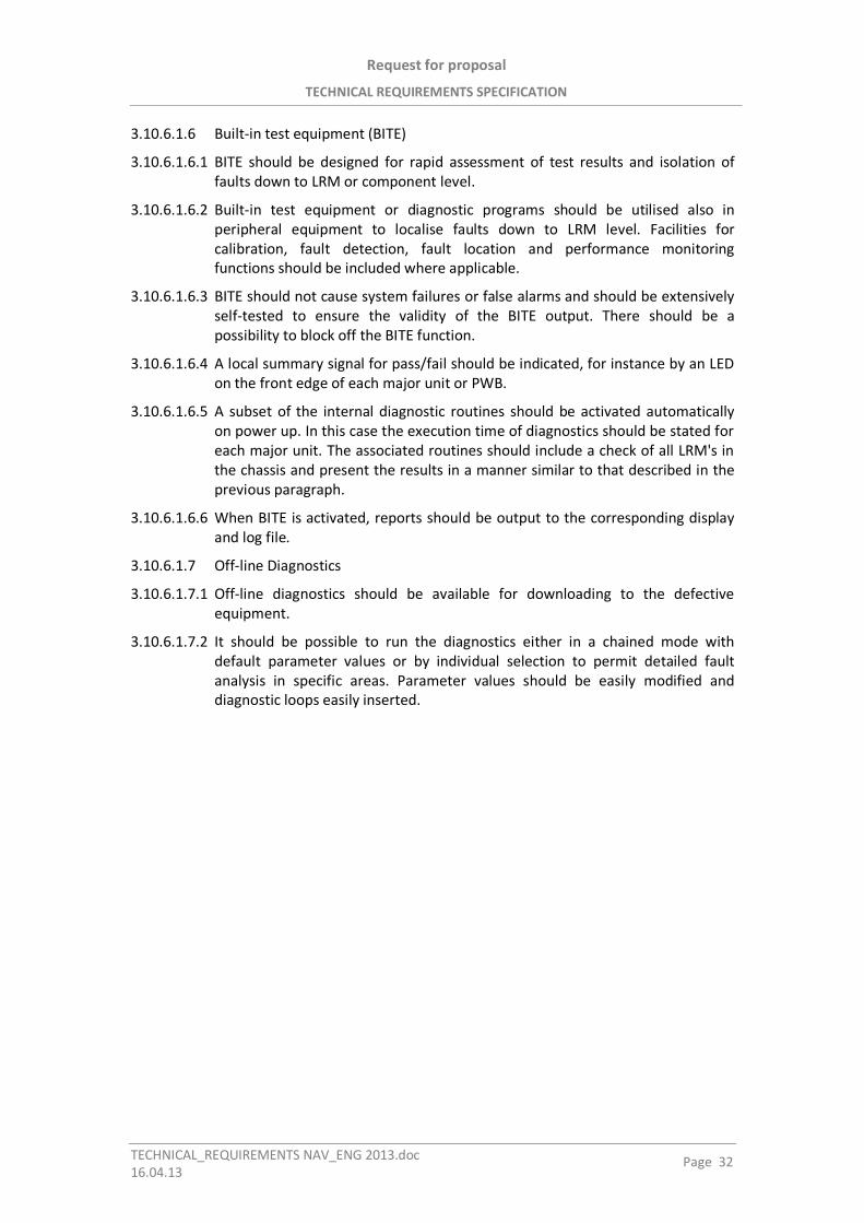
Request for proposal
TECHNICAL REQUIREMENTS SPECIFICATION
TECHNICAL_REQUIREMENTS NAV_ENG 2013.doc16.04.13
Page 32
3.10.6.1.6 Built-in test equipment (BITE)
3.10.6.1.6.1 BITE should be designed for rapid assessment of test results and isolation offaults down to LRM or component level.
3.10.6.1.6.2 Built-in test equipment or diagnostic programs should be utilised also inperipheral equipment to localise faults down to LRM level. Facilities forcalibration, fault detection, fault location and performance monitoringfunctions should be included where applicable.
3.10.6.1.6.3 BITE should not cause system failures or false alarms and should be extensivelyself-tested to ensure the validity of the BITE output. There should be apossibility to block off the BITE function.
3.10.6.1.6.4 A local summary signal for pass/fail should be indicated, for instance by an LEDon the front edge of each major unit or PWB.
3.10.6.1.6.5 A subset of the internal diagnostic routines should be activated automaticallyon power up. In this case the execution time of diagnostics should be stated foreach major unit. The associated routines should include a check of all LRM's inthe chassis and present the results in a manner similar to that described in theprevious paragraph.
3.10.6.1.6.6 When BITE is activated, reports should be output to the corresponding displayand log file.
3.10.6.1.7 Off-line Diagnostics
3.10.6.1.7.1 Off-line diagnostics should be available for downloading to the defectiveequipment.
3.10.6.1.7.2 It should be possible to run the diagnostics either in a chained mode withdefault parameter values or by individual selection to permit detailed faultanalysis in specific areas. Parameter values should be easily modified anddiagnostic loops easily inserted.

RASĒJUMI
DRAWINGS
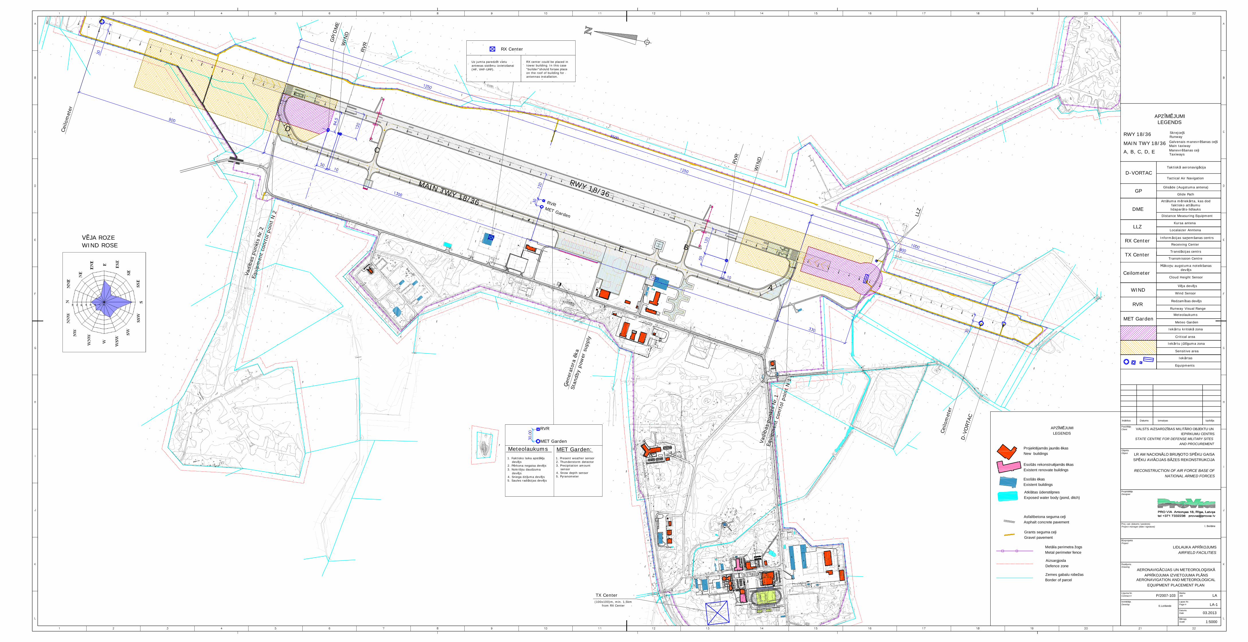
Ceilometer
M ko u augstuma noteikšanasdev js
Cloud Height Sensor
WINDV ja dev js
Wind Sensor
RVRRedzam bas dev js
Runway Visual Range
MET GardenMeteolaukums
Meteo Garden
RX CenterReceiving Center
Inform cijas sa emšanas centrs
TX CenterTransmission Centre
Transl cijas centrs
APZ JUMILEGENDS
RWY 18/36 Skrejce šRunway
MAIN TWY 18/36 Galvenais manevr šanas ce šMain taxiway
A, B, C, D, E Manevr šanas ce iTaxiways
D-VORTACTaktisk aeronavig cija
Tactical Air Navigation
GPGlis de (Augstuma antena)
Glide Path
DME
Att luma m riek rta, kas dodfaktisko att lumulidapar ts-lidlauks
Distance Measuring Equipment
LLZLocalaizer Anntena
Kursa antena
Iek rtu kritisk zona
Critical area
Iek rtu j t guma zona
Sensitive area
Iek rtas
Equipments
GP/
DM
E
MET Garden
RVR
RVR
Cei
lom
eter
MET Garden
RVR
Meteolaukums
1. Faktisko laika apst k udev js
2. P rkona negaisa dev js3. Nokriš u daudzuma
dev js4. Sniega dzi uma dev js5. Saules radi cijas dev js
MET Garden:
Uz jumta paredz t vietuantenas sist mu izvietošanai(HF, VHF-UHF).
RX center could be placed intower building. In this case"builder"should forsee placeon the roof of building forantennas installation.
RX Center
A
B
C
D
TX Center(100x100)m, min. 1,5km
from RX Center
RWY 18/36MAIN TWY 18/36
WIN
D
WIN
D
RVR
Cei
lom
eter
LLZ
D-V
ORTA
C
Vad
bas
pun
kts
Nr.
2
Equ
ipm
ent
conr
tol poi
nt N
2
Vad
bas
pun
kts
Nr.
1
Equ
ipm
ent
conr
tol poi
nt N
1
E
ener
ator
a ka
Sta
ndby
pow
er s
uppl
y
1. Present weather sensor2. Thunderstorm detector3. Precipitation amount
sensor4. Snow depth sensor5. Pyranometer
LA
E.Leitlande LA-1
1:5000
AERONAVIG CIJAS UN METEOROLO ISKAPR KOJUMA IZVIETOJUMA PL NS
AERONAVIGATION AND METEOROLOGICALEQUIPMENT PLACEMENT PLAN
V JA ROZEWIND ROSE
Projekt jam s jaun s kasNew buildings
Esoš s rekonstru jam s kasExistent renovate buildings
Esoš s kasExistent buildings
Asfaltbetona seguma ce iAsphalt concrete pavement
Grants seguma ce iGravel pavement
Met la perimetra žogsMetal perimeter fence
Atkl tas denstilpnesExposed water body (pond, ditch)
APZ JUMILEGENDS
Zemes gabalu robežasBorder of parcel
AizsargjoslaDefence zone
LR AM NACION LO BRU OTO SP KU GAISASP KU AVI CIJAS B ZES REKONSTRUKCIJA
RECONSTRUCTION OF AIR FORCE BASE OFNATIONAL ARMED FORCES
LIDLAUKA APR KOJUMSAIRFIELD FACILITIES
Pas jsClient
ObjektsObject
Projekt jsDesigner
vprojektsProject
Ras jumsDrawing
03.2013
P/2007-103
I. Beit ne
Izmai asDatumsIndekss Izpild ja
Proj. vad. (datums / paraksts)Project manager (date / signature)
guma Nr.Contract #
Izstr jaDevelop
MarkaJob
Lapas Nr.Page #
DatumsDate
rogsScale
VALSTS AIZSARDZ BAS MILIT RO OBJEKTU UNIEPIRKUMU CENTRS
STATE CENTRE FOR DEFENSE MILITARY SITESAND PROCUREMENT

PIELIKUMI
ATTACHMENTS
Request for proposal
ATTACHMENTS. NAVIGATION SYSTEM, COMMUNICATIONS SYSTEM
Attachment NAV_ENG 2013_1.docx - 1 - 30.04.13
TABLE OF CONTENTS
1. INSTALLATION AND TRANSITION OPERATIONAL IMPACT .............................. 5
1.1 SITE SURVEYS ................................................................................................................... 5 1.1.1 General.................................................................................................................. 5 1.1.2 The distance from the runway, taxiways and apron ............................................ 5 1.1.3 The complexity of the landmark ........................................................................... 5 1.1.4 The presence of the other obstacles ..................................................................... 5 1.1.5 The interference with other equipment ................................................................ 5 1.1.6 The establishing of the infrastructure ................................................................... 6
1.2 SURVEY’S PRIORITY ........................................................................................................... 6 1.2.1 General.................................................................................................................. 6
1.3 REQUIREMENTS TO THE NAVIGATIONAL EQUIPMENT .............................................................. 7 1.3.1 ILS .......................................................................................................................... 7
1.4 SCHEMATIC DRAWING OF THE PLACEMENT ................................................................ 8
2. INSTRUMENT LANDING SYSTEM ILS CAT III.................................................. 10
2.1 SCOPE .......................................................................................................................... 10 2.1.1 ILS CAT III according ICAO Annex 10 ................................................................... 10 2.1.2 Auxiliary Services ................................................................................................ 10 2.1.3 References ........................................................................................................... 10
2.2 ICAO STANDARDS .......................................................................................................... 10 2.2.1 ICAO- Annex 10, Volume 1, Part 1 ...................................................................... 10 2.2.2 ICAO- Annex 10, Volume 1, Part 2 ...................................................................... 11 2.2.3 ICAO- Annex 14, Volume 1 .................................................................................. 11 2.2.4 ICAO- DOC 8071, Volume 11 ............................................................................... 11
2.3 EQUIPMENT REQUIREMENTS ............................................................................................ 11 2.3.1 General Requirements ........................................................................................ 11 2.3.2 Special Requirements .......................................................................................... 16
2.4 SUPPORTING SERVICES .................................................................................................... 29 2.4.1 Site Survey ........................................................................................................... 29 2.4.2 Installation/Commissioning ................................................................................ 29 2.4.3 Acceptance Testing ............................................................................................. 29 2.4.4 Flight Testing ...................................................................................................... 29 2.4.5 Technical Manuals .............................................................................................. 30 2.4.6 Maintenance Philosophy/ Spare Parts/ Test Equipment .................................... 30 2.4.7 After sales Service ............................................................................................... 30 2.4.8 Configuration Control ......................................................................................... 30
3. DISTANCE MEASURING EQUIPMENT (DME) ................................................. 32
3.1 SCOPE .......................................................................................................................... 32 3.1.1 DME according ICAO Annex 10 ........................................................................... 32 3.1.2 Basic Versions ..................................................................................................... 32 3.1.3 Auxiliary Services, ............................................................................................... 32 3.1.4 References ........................................................................................................... 32
3.2 STANDARDS ................................................................................................................... 32 3.2.1 Standards of General Application ....................................................................... 32 3.2.2 Standards of Special Application ........................................................................ 33
3.3 EQUIPMENT REQUIREMENT .............................................................................................. 33 3.3.1 General Requirement .......................................................................................... 33
Request for proposal
ATTACHMENTS. NAVIGATION SYSTEM, COMMUNICATIONS SYSTEM
Attachment NAV_ENG 2013_1.docx - 2 - 30.04.13
3.3.2 Engineering ......................................................................................................... 38 3.3.3 Reliability ............................................................................................................ 39 3.3.4 Manufacturing, Testing and Quality Assurance ................................................. 39 3.3.5 Technical Documentation ................................................................................... 39 3.3.6 Installation .......................................................................................................... 39 3.3.7 Operation ............................................................................................................ 39 3.3.8 Maintenance ....................................................................................................... 40
3.4 FUNCTIONAL REQUIREMENTS ........................................................................................ 40 3.4.1 General................................................................................................................ 40 3.4.2 Control and Monitor System ............................................................................... 41 3.4.3 Remote Control and Monitoring System ............................................................ 47 3.4.4 Technical Specifications ...................................................................................... 48
3.5 ANTENNA SYSTEM ...................................................................................................... 49
4. VOICE COMMUNICATION SYSTEM .............................................................. 51
4.1 TECHNICAL SPECIFICATIONS REQUESTED FOR VCCS .............................................................. 51 4.1.1 System Configuration (Tentative) ....................................................................... 51 4.1.2 System Management & Maintenance ................................................................ 51 4.1.3 Operational Capabilities ..................................................................................... 52 4.1.4 Performance Capabilities .................................................................................... 52 4.1.5 Functional Capabilities ........................................................................................ 54
5. REQUIREMENT SPECIFICATIONS TO VHF/UHF RADIOS ................................. 60
5.1 TECHNICAL SPECIFICATIONS REQUESTED FOR VHF/UHF RADIOS ............................................ 60 5.1.1 Equipment’s Requirements ................................................................................. 60 5.1.2 VHF-UHF Wideband Antenna ............................................................................. 62
6. REQUIREMENT SPECIFICATIONS TO HF RADIOS ........................................... 64
6.1 TECHNICAL SPECIFICATIONS REQUESTED FOR HF RADIOS ....................................................... 64 6.1.1 Equipment’s Requirements ................................................................................. 64 6.1.2 HF Antenna Requirements .................................................................................. 65
7. RECORDER SYSTEM ..................................................................................... 67
7.1 TECHNICAL REQUIREMENTS TO THE RECORDING SYSTEM ...................................................... 67 7.1.1 Preamble ............................................................................................................. 67 7.1.2 General requirements ......................................................................................... 67 7.1.3 Required Input/Output Interfaces....................................................................... 69
8. TACTICAL AIR NAVIGATION D-VORTAC........................................................ 71
8.1 INTRODUCTION .............................................................................................................. 71 8.1.1 Objectives ............................................................................................................ 71 8.1.2 Bidder’s Responsibility ........................................................................................ 71
8.2 SCOPE OF WORK AND SUPPLY ........................................................................................... 72 8.2.1 Systems Engineering ........................................................................................... 72 8.2.2 Cabinets and Antenna System ............................................................................ 72 8.2.3 Site Survey ........................................................................................................... 72 8.2.4 Flight Trials (inspection) and Assistance during Flight Trials .............................. 73 8.2.5 D-VORTAC Site .................................................................................................... 73 8.2.6 Site Services Requirements ................................................................................. 73 8.2.7 Mains Supply ....................................................................................................... 74
Request for proposal
ATTACHMENTS. NAVIGATION SYSTEM, COMMUNICATIONS SYSTEM
Attachment NAV_ENG 2013_1.docx - 3 - 30.04.13
8.2.8 Telecommunication Services ............................................................................... 75 8.2.9 Maintenance Adjustments and Test Points ........................................................ 76 8.2.10 Maintenance Actions during Operation ............................................................. 76 8.2.11 Exact Site Co-ordinates and Heights ................................................................... 76
8.3 D-VORTAC TECHNICAL SPECIFICATIONS ............................................................................ 77 8.3.1 Specification and Standards ............................................................................... 77 8.3.2 Alternatives ......................................................................................................... 77 8.3.3 General Requirements ........................................................................................ 77 8.3.4 Technical Requirements for D-VORTAC equipment ............................................ 78 8.3.5 Operator position of D-VORTAC equipment ....................................................... 80 8.3.6 Control and Monitoring System (CMS) ............................................................... 80 8.3.7 D-VORTAC Control interrogator and Antenna .................................................... 83 8.3.8 Antenna System .................................................................................................. 83

Request for proposal
ATTACHMENT 1. SITE SURVEYS
Attachment NAV_ENG 2013.doc - 4 -16.04.13
1. PIELIKUMS / ATTACHMENT 1
Instal šanas darbi un p rejas ekspluat cijasietekme
Vietas izp te
Installation and transition operational impactSite Surveys
Request for proposal
ATTACHMENT 1. SITE SURVEYS
Attachment NAV_ENG 2013.doc - 5 -16.04.13
1. Installation and Transition Operational Impact
1.1 Site surveys
1.1.1 General
1.1.1.1 The main task of the site survey is to define the right type, number and positionfor the equipment’s placement on the airfield.
1.1.1.2 The site survey should be performed by the Bidder for each type of theequipment separately.
1.1.1.3 There are a lot of factors, which could affect to the right placement of thedifferent types of the equipment.
1.1.1.4 At least the following factors should be taken into account:
1.1.1.4.1 Distance from the runway, taxiways and apron;
1.1.1.4.2 The complexity of the landmark for the installation and cabling works;
1.1.1.4.3 The presence of the other obstacles in the proximity to the equipment;
1.1.1.4.4 The interference between the different types of the equipment;
1.1.1.4.5 The necessity to create the infrastructure for the proper maintenance of theequipment in the future.
1.1.2 The distance from the runway, taxiways and apron
1.1.2.1 The placement of the equipment should be done strictly in according with theICAO, WMO and NATO rules.
1.1.3 The complexity of the landmark
1.1.3.1 The necessity of the civil works including ground levelling, drainage, cutting oftrees and bushes, etc. should be taken into account for the each type of theequipment according to the requirements.
1.1.4 The presence of the other obstacles
1.1.4.1 There are a number of rules defined for the objects on the airfield. These rulesare described in the corresponding documents.
1.1.4.2 There are the number of the parameters such as height, for example, whichshould not exceed the certain limits depending on distance from runway andtaxiways.
1.1.5 The interference with other equipment
1.1.5.1 It should be taken into account the possible interference with other type of theequipment installed on the airfield.
1.1.5.2 There is the number of rules for each type of the equipment. These rules areprescribed in the corresponding documents/attachments.
Request for proposal
ATTACHMENT 1. SITE SURVEYS
Attachment NAV_ENG 2013.doc - 6 -16.04.13
1.1.6 The establishing of the infrastructure
1.1.6.1 The each type of the equipment should be connected to the power andcommunication network (there are a few exceptions exist)
1.1.6.2 The power network infrastructure should be created to provide the adequateand suitable power mains for each object on the airfield.
1.1.6.3 The reasonable number of the power distribution units and diesel-generatorsshould be installed.
1.1.6.4 It is possible to share the one power distribution unit for several objects on theairfield.
1.1.6.5 The communication network should be built based on 2 major criteria:
1.1.6.5.1 It should be redundant for every object;
1.1.6.5.2 The topology of the network should be optimized. For example, it is possible touse one cable trench for the communication network provision till severalobjects. The pipes will be shared in that case.
1.1.6.6 The area around every object should be prepared for the further maintenance.It should be possible to make every object accessible by car all year round.
1.2 Survey’s priority
1.2.1 General
1.2.1.1 It is very important to define the priority of the surveys.
1.2.1.2 The every next survey should take into account the results from the previoussurveys.
1.2.1.3 The sequence of the surveys is described below:
1.2.1.3.1 The navigation Aids – ILS, D-VORTAC;
1.2.1.3.2 The meteorological equipment – Wind/Visibility/Clouds Sensors, etc.;
1.2.1.3.3 Communication (Transmitters/Receivers) center.
1.2.1.4 It should be necessary to create a map/detailed scheme of the airfield, whereall the survey’s results should be reflected.
1.2.1.5 This map should be up to date.
Request for proposal
ATTACHMENT 1. SITE SURVEYS
Attachment NAV_ENG 2013.doc - 7 -16.04.13
1.3 Requirements to the Navigational Equipment
1.3.1 ILS
1.3.1.1 The instrument landing system (ILS) The ILS uses a line-of-sight signal from thelocalizer antenna and marker beacons and a reflected signal from the groundplane in front of the glide slope antenna.
1.3.1.2 ILS antenna systems are susceptible to signal interference sources such aspower lines, fences, metal buildings, etc.
1.3.1.3 Since ILS uses the ground in front of the glide slope antenna to develop thesignal, this area should be graded to remove surface irregularities.
1.3.1.3.1 The Localizer Antenna (LLZ) signal is used to establish and maintain theaircraft's horizontal position until visual contact confirms the runway alignmentand location. The LLZ antenna is sited on the extended runway centerline 1,000to 2,000 feet (300 to 600 m) beyond the stop end of the runway. The LLZequipment shelter is placed at least 250 feet (75 m) to either side of theantenna array and within 30 degrees of the extended longitudinal axis of theantenna array.
1.3.1.3.2 The Glide Slope Antenna (GP) signal is used to establish and maintain theaircraft's descent rate until visual contact confirms the runway alignment andlocation. A GP differentiates precision from non-precision approaches. The GPantenna may be located on either side of the runway. The most reliableoperation is obtained when the GP is located on the side of the runway offeringthe least possibility of signal reflections from buildings, power lines, vehicles,aircraft, etc.
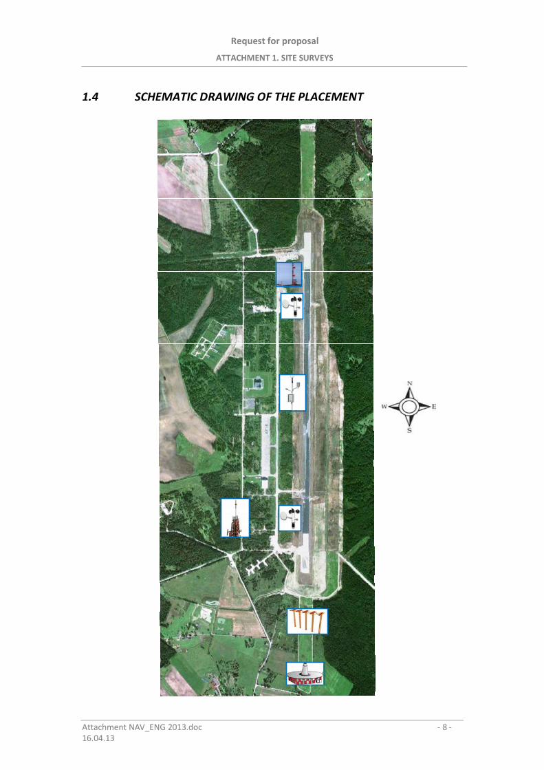
Request for proposal
ATTACHMENT 1. SITE SURVEYS
Attachment NAV_ENG 2013.doc - 8 -16.04.13
1.4 SCHEMATIC DRAWING OF THE PLACEMENT

Request for proposal
ATTACHMENT 2. INSTRUMENT LANDING SYSTEM ILS CAT III
Attachment NAV_ENG 2013.doc - 9 -16.04.13
2. PIELIKUMS / ATTACHMENT 2
Instrument l nos šan s sist ma ILS CAT III
Instrument Landing System ILS CAT III
Request for proposal
ATTACHMENT 2. INSTRUMENT LANDING SYSTEM ILS CAT III
Attachment NAV_ENG 2013_1.docx - 10 - 30.04.13
2. INSTRUMENT LANDING SYSTEM ILS CAT III
2.1 Scope
2.1.1 ILS CAT III according ICAO Annex 10
This Specification covers all items required to procure an ILS in terms of the relevant ICAO Annex 10 Specifications (section 3.1) for Category III service level.
2.1.1.1 Basic Equipment
Two Frequency Localizer Station (LOC)- System (2F)
Two Frequency M - Type System (M-Type)
Remote Maintenance Management Configuration (RMMC)
Far Field Monitoring (FF- Monitor)
2.1.1.2 Additional Equipment
Omni directional DME for Marker Substitution
Note: The DME and the remote control versions are subject to separate specifications
2.1.2 Auxiliary Services
such as:
Mains- and Battery Power Supply
Signaling line interfaces
Shelters
Frame work, masts and poles
RF- cabling
are specified in brief terms.
2.1.3 References
The Tenderer is requested to make proof in his proposal to manufacture at least ILS, DME and DVOR equipment in his own premises and shall include references on worldwide installations performed.
2.2 ICAO Standards
The following ICAO Standards shall be met as applicable to the ILS configuration class, in their latest edition and including latest amendments:
2.2.1 ICAO- Annex 10, Volume 1, Part 1
Chapter 3, Section 3.1: Specification for ILS
Chapter 3, Section 3.6: Specification for en- route VHF marker beacons (75MHz)
Request for proposal
ATTACHMENT 2. INSTRUMENT LANDING SYSTEM ILS CAT III
Attachment NAV_ENG 2013.doc - 11 -16.04.13
Attachment C to Part 1: Section 1 and 2- Material concerning ILSinstallations
Attachment C to Part 1: Section 8- Material concerning power supply switchover times
Attachment F to Part 1: Guidance material concerning reliability andavailability of radio communications andnavigation aids
2.2.2 ICAO- Annex 10, Volume 1, Part 2
Chapter 4, Section 4.2.- (Frequency-) Utilisation in the band 108-117,995MHz
2.2.3 ICAO- Annex 14, Volume 1
Chapter 4, Section 4. 1: Obstacle limitation surfaces
2.2.4 ICAO- DOC 8071, Volume 11
Manual on Testing of Radio Navigation Aids, ILS
2.3 Equipment Requirements
The equipment proposed by the Tenderer shall comply with the requirementsdescribed below. The compliance shall be supported by a point- to - pointstatement to be included in the Tenderers proposal.
2.3.1 General Requirements
2.3.1.1 Electrical Requirements
2.3.1.1.1 Input Voltage
The AC input voltage shall be:
230 Volts or 115 Volts nominal
Tolerance: +10%, -15%
Frequency: 48 to 64 Hz
2.3.1.1.2 Battery Protection
Automatic protection against battery overcharging shall be incorporated in thepower supply.
2.3.1.1.3 Stray Radiation
The power supply/charger unit shall not emit any stray radiation causinginterference to radio environment. The radio interference classification shall belisted in the Tenderer's proposal.
2.3.1.1.4 DC Supply Voltage
The DC output shall provide a nominal voltage below or equal to +48 Volt at acurrent sufficient to operate the equipment and charge batteries at the sametime. Interdependent voltage and current regulation shall be provided.
2.3.1.1.5 Battery Charging Power Supply Configuration

Request for proposal
ATTACHMENT 2. INSTRUMENT LANDING SYSTEM ILS CAT III
Attachment NAV_ENG 2013.doc - 12 -16.04.13
Independent power supply units shall share the charging of the commonbattery set and the equipment load from a common bus bar. The arrangementshall be a dual configuration; i.e. for a dual equipment configuration 2 powersupply units shall share the load. In case of removal or failure of one unit theequipment supply shall not be interrupted, the remaining power supply unitshall still be capable to supply the dual equipment, only the battery chargingperiod is allowed to be increased. The charging time (from 10%-90% batterycapacity) shall not exceed:
10 hours for full power supply configuration
2.3.1.2 Mechanical Requirements
2.3.1.2.1 Configuration
The electronic equipment shall be mounted in a 19" cabinet installed in ashelter. The frame work shall be of galvanised steel or anodised aluminium.
2.3.1.2.2 Modular Construction
For rapid replacement of units, the cabinet shall contain equipment carriers, inwhich individual plug in units and modules shall be inserted. Drawers will not beaccepted.
All plug-in units and modules (including RF-modules) shall fit on slide rails andshall be removable from the front of the cabinet. Connectors shall be keyed toprevent insertion of units in the wrong way or into a wrong slot. Also the RF-Connectors of the modules shall be plug-in type.
2.3.1.2.3 Plug-In Units
2.3.1.2.3.1 Printed Circuit Boards
Printed circuit boards shall be used exclusively, also for inter wiring betweencircuits inside of plug-in units (printed mother boards). For reliability reasonsprinted mother boards shall also be used for cabinet and sub-assembly interwiring.
2.3.1.2.3.2 Coatings
Printed circuits shall be coated by a photo solder resistant material in order toincrease the electrical resistance of the surface, and to decrease the surgingeffect of moisture and fungus on unprotected insulating surfaces.
The printed circuit board coating shall permit the replacement of componentsby soldering techniques without destroying the coating or the board surface.
2.3.1.2.3.3 Controls
In order to avoid ware and tare, no mechanically operating control elementsshall be accepted for direct signal adjustment. There shall be no potentiometersin the direct path of signal generation. The number of potentiometers shall belimited to DC alignments.
In case of variable inputs, potentiometers shall be located on the front of theboard, as to permit setting without removing the board or needing a cardextender. Push buttons for input/output control and men/machine dialogueshall be sealed and protected against environmental effects.
2.3.1.2.3.4 Radio-Frequency Connections
Request for proposal
ATTACHMENT 2. INSTRUMENT LANDING SYSTEM ILS CAT III
Attachment NAV_ENG 2013.doc - 13 -16.04.13
RF cable connections within the electronic equipment shall be effected bymeans of coaxial connectors, throughout. RF cabling and interconnectionsbetween plug-in units and modules shall be located at the rear of the cabinet orsubrack by plug-in type connectors for the RF-modules. RF connections to thetransmitting antenna system shall be accessible on RF output connectorslocated on the top of the cabinet.
2.3.1.2.4 Wiring
Inter wiring of units within subassemblies shall be made via mother boards(printed circuits).
2.3.1.2.5 Ventilation
Cooling inside the cabinet shall be effected by convection exclusively and shallassure all components to operate well within their individual temperatureratings within the specified equipment ambient temperature range. Cooling byfans is not accepted. Heat sinks for power components and power circuits shallbe separated from low-power circuits to avoid unnecessary heat stress tolow-power circuits.
2.3.1.2.6 Shelter
Equipment shelters shall be compact and completely fitted in a way, that plug-in units and modules need to be inserted and exterior cabling have to beconnected to the respective distribution panels to assure a short installationtime on site. Shelters shall be light-weight and shall be designed to serve as aself-supporting container for transportation. Shelter material shall be noncorrosive.
Wall and ceiling elements shall be sandwich panels made of 1,2 mm thickAlMgSi sheeting on the inner and outer side. Between the two sheets thermalinsulation of 40 mm thick polyurethane hard-foam shall be provided. Thedimensions of the shelter shall be according to container standards, the lengthshall be at least 15 feet. The shelter shall be complete with all electricalinstallation, power distributors and signal and RF- distribution boxes. A built-inbattery compartment shall be provided. The dual set of heaters and airconditioning equipment shall integrated, the respective openings and supportsshall be provided. The outside shelter surfaces shall be coated with warningpaint acc. to RAL 2002. Foundation drawings with static calculation shall beprovided after contract award.
2.3.1.2.7 Localiser Antenna Array
2.3.1.2.7.1 Support Construction
The construction shall be self- supported comprising supports. The RF- powerdistribution network shall be housed in a weather-proof metal box.
2.3.1.2.7.2 Dual Frequency Antenna Concept
In a two frequency antenna system course and clearance antennae shall beintegrated.
2.3.1.2.7.3 Height
In order to maintain obstruction clearances in terms of ICAO- Annex 14, theheight of the localiser antenna shall be adopted for installation place. The
Request for proposal
ATTACHMENT 2. INSTRUMENT LANDING SYSTEM ILS CAT III
Attachment NAV_ENG 2013.doc - 14 -16.04.13
structure shall be light weight and frangible to prevent hazardous damage to airmobiles in case of collision.
2.3.1.2.7.4 Dual Frequency Antenna Concept
In a two frequency antenna system course and clearance antennae shall beintegrated.
2.3.1.2.7.5 Course Clearance Isolation
Isolation of course and clearance systems shall be >30 dB to minimiseinteractions.
2.3.1.2.8 Glide Slope Antenna Array
2.3.1.2.8.1 GS Mast
The Glide Slope antenna mast shall be adopted to ICAO frangibilityrequirements, to avoid severe damages to air mobiles in case of collision.
2.3.1.2.8.2 Antenna Array
The glide-slope antenna array shall be designed for use in M- Type mode(capture effect clearance) configuration, without requiring adjustment ormodification.
2.3.1.2.9 RF- Cabling
2.3.1.2.9.1 Antenna Feeding Cables
The RF feeder cables between antenna elements and power distributionnetwork should have the same length and the connections shall be made viaplugs and sockets of the N-type. Adequate protection shall be provided againstmechanical damage.
2.3.1.3 Environmental Requirements
2.3.1.3.1 Windage
The ILS antenna structures shall withstand wind velocities up to 160 km/h foroperation (survival 200 km/h, survival 144 km/h with 1.5cm ice load).
2.3.1.3.2 Ice Loading
Ice loads up to 5cm thickness shall not cause any damage to shelters andantenna structures.
2.3.1.3.3 Antenna Cover
Antenna elements shall be protected by glassfiber- reinforced polyester covers
2.3.1.3.4 Indoor Temperature
Indoor equipment shall operate within their specifications:
Ambient temperature -10°C to + 55°C
Relative humidity <95% in the range of –10°C to +35°C
<60% in the range of + 35°C to 55°C
2.3.1.3.5 Outdoor Temperature
Outdoor equipment and material shall withstand without any damage ordeformation:
Request for proposal
ATTACHMENT 2. INSTRUMENT LANDING SYSTEM ILS CAT III
Attachment NAV_ENG 2013.doc - 15 -16.04.13
Ambient temperature -40°C to + 70°C
Relative humidity up to 100%
2.3.1.3.6 Outdoor Cabinets
Electronic equipment shall be housed in suitably designed compartments, whichshall be sealed against access of water, salt, vermin and shall be of noncorrosive material.
2.3.1.3.7 Environmental Requirements
Outdoor elements, structures, shelters and others shall be designed andconstructed to withstand site typical effects as salt, rain, hail, thunderstorms,attacks of small to medium animals (e.g. dogs, rabbits), without damage ornoticeable deformation.
2.3.1.3.8 Temperature Variation
All equipment shall operate within their specifications (without damage ormalfunction) during Temperature variation of up to 20°C within 24 hrs.
2.3.1.4 System Configuration
2.3.1.4.1 Equipment Cabinet
The system concept shall be such as to accommodate at least two independentequipment sections (either dual version) in a single 19" standard size cabinet.The power supply and charger units shall be integrated into the electronicequipment, and shall be housed in the same cabinet. The respective safetyregulations shall be observed. Heat protections between the power supply andthe electronic equipment shall prevent heat dissipation from penetrating theelectronic part.
2.3.1.4.2 Monitoring
The monitoring system shall be modular and shall allow for ICAO- Cat. I to Cat.III alarm threshold settings by Portable Maintenance Data Terminal (PMDT –Laptop) entry only. Upgrading from Cat. I monitoring up to ICAO- Cat. IIImonitoring shall be effected by adding modules, only.
2.3.1.4.3 Antenna Concept
The antenna concept shall be modular; i.e. antenna elements shall be identical,irrespective of their use in Cat. I, II, III configuration or in single or twofrequency versions.
2.3.1.5 Quality Assurance
2.3.1.5.1 Certifications
The Tenderer shall be an ISO 9000 certified manufacturer. The production ofthe proposed NAVAIDS shall fall under the ISO 9000 certificate.
Hardware and software design, quality assurance in the production process, aswell as documentation shall be in line with ISO 9000 series.
2.3.1.5.2 Burn-In
Components and sub units shall undergo "burn- in" tests during production.
Request for proposal
ATTACHMENT 2. INSTRUMENT LANDING SYSTEM ILS CAT III
Attachment NAV_ENG 2013.doc - 16 -16.04.13
The complete system shall be subject to "burn- in" testing at a temperature of50°C at least 48 hrs.
2.3.1.6 MTBF (Mean Time Between Failure)
2.3.1.6.1 Reliability Prediction
Reliability predictions shall be included in the Tenderer's proposal. They shall bein line with the procedures of MIL-Handbook 217 F2 and the specifications givenin the ICAO, Annex 10, Attachment F to Part 1, Edition 1985.
2.3.1.6.2 MTBF Calculation
The calculation of the MTBF value shall be performed by means of a finalreliability prediction. Only calculations will be accepted which are in accordancewith the corresponding sections of the MIL-Handbook 217 F2 (Paragraphs 5, 6,7, 8, 9). The calculation shall be based upon the worst environmental conditionsgiven in paragraph 2.2 of this specification.
For the purpose of calculating the MTBF, a failure shall be defined as anycondition wherein the radiated signal fails to meet all the requirements of thisspecification as given by indication on the monitor system.
For the MTBF calculation the equipment configuration shall be as the proposedsystem including antennae and monitors.
2.3.1.6.3 MTBF Figures
The ambient temperature shall be + 50°C. The mean time to repair (MTTR) shallbe 0.5 hours.
The MTBF figures for equipment, dual channel, as specified above shall bebelow :
LOC-2F 18 000 hrs
GS -2F 26 000 hrs
based upon continuous operation under the worst combination of theoperation conditions.
2.3.2 Special Requirements
2.3.2.1 Design Concept and Circuit Philosophy
2.3.2.1.1 Equipment Category
The equipment characteristics and signal quality (accuracy and stability) shallmeet the
ICA0- Annex 10 requirement for Cat III equipment performance,
2.3.2.1.2 Signal Generation
The control of signal generation shall be digital throughout.
2.3.2.1.3 Monitor Processing
The monitor system shall be based on digital signal processing throughout.Signal analysis shall be based on discrete Fourier analysis techniques.
2.3.2.1.4 Transmitter Processing
Request for proposal
ATTACHMENT 2. INSTRUMENT LANDING SYSTEM ILS CAT III
Attachment NAV_ENG 2013.doc - 17 -16.04.13
The feedback loop for sideband control shall be digital.
2.3.2.1.5 Monitor Alarm Settings
Since the ILS shall meet category III equipment performance, alarm thresholdssetting for lower categories shall be effected digitally by Portable MaintenanceData Terminal (PMDT – Laptop) settings.
2.3.2.1.6 2F System Capability
2.3.2.1.6.1 Localizer 2F with Out-Of-Phase Clearance
In order to reduce effects of multipath reflections from existing or futurehangars and buildings, and from aircraft on taxiways and aprons, the localisertransmitter and the corresponding antenna system are to be offered as a twofrequency version.
Out of phase clearance shall be offered optionally.
2.3.2.1.6.2 Glide Slope System:
To reduce the effects on GS signals of terrain irregularities in the near andmedium distance of the approach, the GS shall be offered as a two frequencyversion (M-type).
2.3.2.1.7 Transmitter Design
2.3.2.1.7.1 RF-Transmitter Design
Wide band design operating from 108 to 112 MHz for localiser and 329 to 335MHz for glide slope transmitters without tuning shall be provided.
The CSB output power of two the frequency localiser transmitter shall be 25 Weach for course - and for clearance signal.
The CSB output power of the two frequency glide slope transmitter shall be 5 Wfor course transmitter and 3 W for clearance signal.
The Glide Slope M-Type transmitter shall have the capability to generate thecourse signals for the antennas A1, A2 and A3 individually.
2.3.2.1.7.2 Frequency Synthesizer
The channel frequency of the ILS transmitters shall be provided by a digitallycontrolled synthesiser in increments of 50 kHz. A Direct Digital Synthesis (DDS)Concept shall be used. To reduce the number of spare parts, the synthesizershall be capable to be used for the localizer as well for the glide slopetransmitter
2.3.2.1.7.3 Carrier (CSB) – and Sideband Only (SBO) Signal Generation
In order to facilitate the necessary field adjustment of course width, both LOC-and GS-transmitter RF-signal generation shall be based on individualmodulation circuits for the CSB- and SBO signals, combined with the respectivephase control between CSB and SBO signals.
2.3.2.1.7.4 RF Impedance and Mismatching
The power amplifiers shall operate into a 50 Ohm load. They shall withstandwithout damage any open or short circuit at the transmitter output or withinthe antenna system (infinite VSWR). In case of short or open circuit a warningindication shall be provided.
Request for proposal
ATTACHMENT 2. INSTRUMENT LANDING SYSTEM ILS CAT III
Attachment NAV_ENG 2013.doc - 18 -16.04.13
2.3.2.1.8 Modulator
2.3.2.1.8.1 CSB Modulation
The CSB-modulation which is essential for course stability shall be derived froma digital modulation signal source. The signal amplitude and signal phasestability shall be controlled by an envelope feedback circuit.
2.3.2.1.8.2 SBO Modulation
The SBO-modulation shall be derived from a digital modulation source. The SBOgeneration shall consist of two analog signals, the I (in phase) and Q(quadrature) component that control RF phasing. It provides modulationtechniques with very low phase modulation. In order to generate coherentsignals on CSB and SBO both signal memories shall use identical addresses forthe digital signal readout.
2.3.2.1.8.3 SBO Carrier Suppression
The carrier suppression at the SBO output shall be at least 30 dB.
2.3.2.1.8.4 Morse Code
The generation of 1020 Hz Morse code characters for identification modulationfor the localizer shall be digitally controlled and shall be programmable viaPMDT. It shall be possible to select either keyed or not keyed modulation or toremove the identity modulation from the LOC-transmitter.
2.3.2.1.8.5 DDM Settings
For test purposes it shall be possible to modulate the CSB LOC transmitterwithin a DDM range of 0 % to ±9.9% at least in steps of 0.1 % at the nominaldepth of modulation (40%).
For test purposes it shall be possible to modulate the CSB GS transmitter withina DDM range of 0 % to ±19.9% at least in steps of 0. 1 % at the nominal depth ofmodulation (80%).
2.3.2.1.8.6 M-Type Clearance DDM setting
In a two-frequency GS-installation the depth of modulation of the clearancetransmitter shall be selectable.
Modulation frequencies of the clearance transmitter shall be either 90 Hz and150 Hz or 150 Hz only.
2.3.2.1.9 Monitoring
2.3.2.1.9.1 Monitor Design
For precise reproduction of monitor calibrations and of transmitter data themonitor shall have following characteristics:
Digital design and layout of circuitry
Digital setting of alarm limits and thresholds. No passive or active AFfiltering by application of analogue filtering techniques.
Signal analysis by use of a Discrete Fourier Transformation which allows adirect digital measurement of ILS-characteristics such as DDM, SDM andRF-level
Request for proposal
ATTACHMENT 2. INSTRUMENT LANDING SYSTEM ILS CAT III
Attachment NAV_ENG 2013.doc - 19 -16.04.13
Absolute calibration of monitor in depth of modulation, phase, andfrequency in order to use the monitor as a measuring instrument formaintenance and equipment calibration.
The basic monitor system of the ILS offered shall comprise a dualisedmonitoring system.
2.3.2.1.9.2 Monitor Sensors
Each monitoring system shall take its inputs from all of the following sensors:
Field sensor:
- Position of course transmitter
Integral sensors:
- Position of course signal
- Width of course signal
- Width of clearance signal (2F only)
Internal sensors:
- Width of standby course signal
- Width of standby clearance signal (2F only)
Test generator:
- Position of test generator signal (DDM > 0)
2.3.2.1.9.3 Monitor Parameter
Each of the above sensor inputs shall monitor the following signals:
DDM (Difference of depth of modulation)
SDM (Sum of depth of modulation)
RF-level (Radio frequency signal level)
2.3.2.1.9.4 Executive Monitor Parameter
Executive monitor parameters shall be:
Field position of course transmitter
Integral position of course transmitter
Integral width of course transmitter
Integral width of clearance transmitter
transmitter frequency
Warning monitor parameters shall be:
Test Generator position
Internal width of standby course transmitter
Internal width of standby clearance transmitter
Pre alarm of all monitor parameter
2.3.2.1.9.5 Alarm Memory
Request for proposal
ATTACHMENT 2. INSTRUMENT LANDING SYSTEM ILS CAT III
Attachment NAV_ENG 2013.doc - 20 -16.04.13
Memory circuits shall be included in the monitor system to indicate whichparameter beyond the alarm limits has caused a ´change over´ or ´shut down´.
Memory circuits for change-over or shut-down parameters shall be accessiblevia telephone line through the remote control and monitoring device.
2.3.2.1.9.6 Integrity Check
An automatic end-to-end integrity check during monitor operation shall beincluded with a minimum repetition rate of 2 seconds for testing and calibrationof the individual monitors.
A monitor unit shall be considered to be faulty if the test generator signalproduces a fault in only one of the monitors. A simultaneous fault in bothmonitors shall define a faulty test generator. One faulty monitor shall cause adowngrading of the equipment category and a warning signal but not ashutdown of the system shall be effected.
2.3.2.1.10 ILS Remote Control
2.3.2.1.10.1 Design Characteristics
The remote control system shall permit remote equipment operation andmaintenance. It shall be designed to operate 2 complete ILS systems eachincluding DME.
The remote control system shall be microprocessor controlled. The transfer ofinformation shall be possible via fibre optic line. The modems shall be includedin both, the transmitter and the remote control cabinets.
2.3.2.1.10.2 Status Display
The remote control display shall indicate the operational status of the ILSsubsystems.
The remote control equipment shall have the capability to indicate theindividual monitor - and transmitter data of the ILS subsystem selected.
2.3.2.1.10.3 Access of a Personal Computer
A remote control input device shall allow the change of monitor- andtransmitter- parameters.
The remote control system shall have access to the results of the transmitterBIT and shall provide the capability of a remote trend analysis and a remotefault analysis.
The remote control equipment shall have interfaces for external readout andexternal input of data.
The following monitoring and print-out operation shall be available
Mains status indication and recording
Subsystem status indication and recording
Transmitter data indication and recording
Monitor data indication and recording
Automatic access documentation
Automatic recording of main status changes
Request for proposal
ATTACHMENT 2. INSTRUMENT LANDING SYSTEM ILS CAT III
Attachment NAV_ENG 2013.doc - 21 -16.04.13
2.3.2.1.10.4 Control Tower Unit (CTU)
Interfaces for Slave Indicators in ATC- departments (tower) shall be included.
2.3.2.1.10.5 Remote Maintenance Centre (RMC) Interface
A serial interface shall be available for communication with an AutomaticDialling System for central data collection and central operation surveillancewith data-, deviation-, and failure- recording.
2.3.2.2 Localiser Antenna
2.3.2.2.1 Polarization
The radiation of the localiser antenna shall be horizontally polarised. When anaircraft is in a bank angle of 20 degrees from horizontal, the vertically polarisedcomponent shall not cause an error value of more then 0,005 DDM within asector of +/- 0.02 DDM (either side of the course line).
2.3.2.2.2 Antenna Concept
Two-frequency localiser systems shall superimpose the clearance pattern ontothe main radiation by feeding an integrated antenna arrays.
2.3.2.2.3 Antenna Element
The Localiser antennas elements shall be log-periodical dipole arrays. Eachradiating element should be provided with a probe to pick-up a part of theundisturbed radiated signal. The feedback to a combination network shall formthe signals for the integral monitor.
Signal processing should be such that the content of the signal corresponds tofar field conditions in the course sector. Thus avoiding occasional changeoversor shutdowns caused by dynamic interferences from overflying or taxiingaircrafts.
2.3.2.2.4 Antenna Systems General Design Characteristics
Mechanical design The mechanical design shall be a buildingblock system, so that expansion is possible byincreasing number of radiator elements.
Frangibility Supporting elements shall be in lightweightdesign, so that they can be run over in anemergency without serious damage to aircraft.
Weatherprotection
The radiator elements shall be protectedagainst the weather by fibre glass reinforcedpolyester covers.
Wind Load Antennas shall resist wind speeds up to 160km/h,
additional guy robes shall be available forhigher wind speeds.
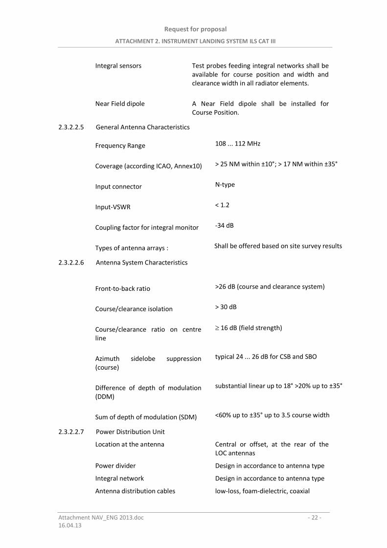
Request for proposal
ATTACHMENT 2. INSTRUMENT LANDING SYSTEM ILS CAT III
Attachment NAV_ENG 2013.doc - 22 -16.04.13
Integral sensors Test probes feeding integral networks shall beavailable for course position and width andclearance width in all radiator elements.
Near Field dipole A Near Field dipole shall be installed forCourse Position.
2.3.2.2.5 General Antenna Characteristics
Frequency Range 108 ... 112 MHz
Coverage (according ICAO, Annex10) > 25 NM within ±10°; > 17 NM within ±35°
Input connector N-type
Input-VSWR < 1.2
Coupling factor for integral monitor -34 dB
Types of antenna arrays : Shall be offered based on site survey results
2.3.2.2.6 Antenna System Characteristics
Front-to-back ratio >26 dB (course and clearance system)
Course/clearance isolation > 30 dB
Course/clearance ratio on centreline
16 dB (field strength)
Azimuth sidelobe suppression(course)
typical 24 ... 26 dB for CSB and SBO
Difference of depth of modulation(DDM)
substantial linear up to 18° >20% up to ±35°
Sum of depth of modulation (SDM) <60% up to ±35° up to 3.5 course width
2.3.2.2.7 Power Distribution Unit
Location at the antenna Central or offset, at the rear of theLOC antennas
Power divider Design in accordance to antenna type
Integral network Design in accordance to antenna type
Antenna distribution cables low-loss, foam-dielectric, coaxial
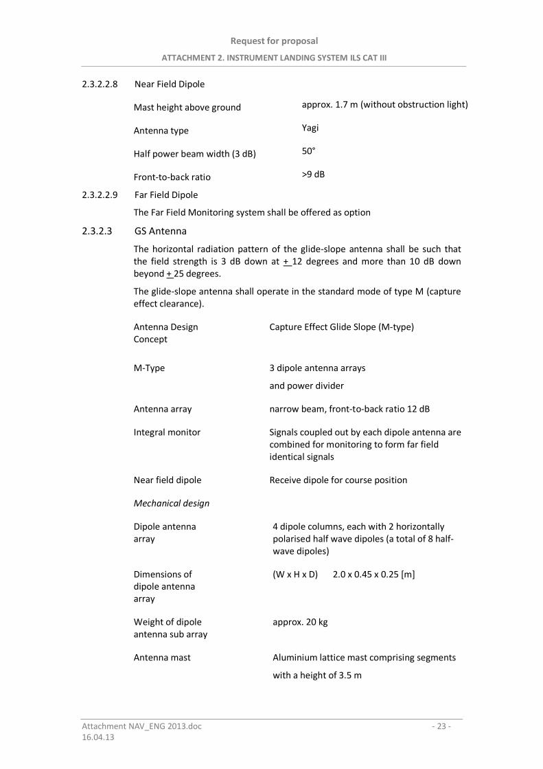
Request for proposal
ATTACHMENT 2. INSTRUMENT LANDING SYSTEM ILS CAT III
Attachment NAV_ENG 2013.doc - 23 -16.04.13
2.3.2.2.8 Near Field Dipole
Mast height above ground approx. 1.7 m (without obstruction light)
Antenna type Yagi
Half power beam width (3 dB) 50°
Front-to-back ratio >9 dB
2.3.2.2.9 Far Field Dipole
The Far Field Monitoring system shall be offered as option
2.3.2.3 GS Antenna
The horizontal radiation pattern of the glide-slope antenna shall be such thatthe field strength is 3 dB down at + 12 degrees and more than 10 dB downbeyond + 25 degrees.
The glide-slope antenna shall operate in the standard mode of type M (captureeffect clearance).
Antenna DesignConcept
Capture Effect Glide Slope (M-type)
M-Type 3 dipole antenna arrays
and power divider
Antenna array narrow beam, front-to-back ratio 12 dB
Integral monitor Signals coupled out by each dipole antenna arecombined for monitoring to form far fieldidentical signals
Near field dipole Receive dipole for course position
Mechanical design
Dipole antennaarray
4 dipole columns, each with 2 horizontallypolarised half wave dipoles (a total of 8 half-wave dipoles)
Dimensions ofdipole antennaarray
(W x H x D) 2.0 x 0.45 x 0.25 [m]
Weight of dipoleantenna sub array
approx. 20 kg
Antenna mast Aluminium lattice mast comprising segments
with a height of 3.5 m
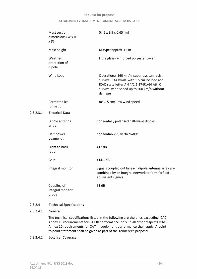
Request for proposal
ATTACHMENT 2. INSTRUMENT LANDING SYSTEM ILS CAT III
Attachment NAV_ENG 2013.doc - 24 -16.04.13
Mast sectiondimensions (W x Hx D)
0.45 x 3.5 x 0.65 [m]
Mast height M-type: approx. 15 m
Weatherprotection ofdipole
Fibre glass-reinforced polyester cover
Wind Load Operational 160 km/h, subarrays can resistsurvival 144 km/h with 1.5 cm ice load acc. IICAO state letter AN 4/1.1.37-91/64 Att. Csurvival wind speed up to 200 km/h withoutdamage
Permitted iceformation
max. 5 cm; low wind speed
2.3.2.3.1 Electrical Data
Dipole antennaarray
horizontally polarised half-wave dipoles
Half-powerbeamwidth
horizontal=25°; vertical=80°
Front to backratio
>12 dB
Gain >14.1 dBi
Integral monitor Signals coupled out by each dipole antenna array arecombined by an integral network to form farfield-equivalent signals
Coupling ofintegral monitorprobe
31 dB
2.3.2.4 Technical Specifications
2.3.2.4.1 General
The technical specifications listed in the following are the ones exceeding lCA0-Annex 10 requirements for CAT III performance, only. In all other respects ICAO-Annex 10 requirements for CAT III equipment performance shall apply. A point-to point statement shall be given as part of the Tenderer's proposal.
2.3.2.4.2 Localiser Coverage
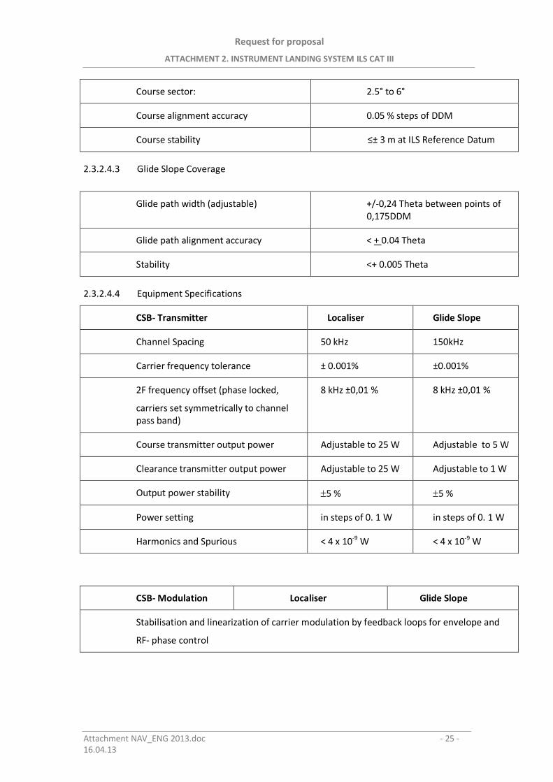
Request for proposal
ATTACHMENT 2. INSTRUMENT LANDING SYSTEM ILS CAT III
Attachment NAV_ENG 2013.doc - 25 -16.04.13
Course sector: 2.5° to 6°
Course alignment accuracy 0.05 % steps of DDM
Course stability ± 3 m at ILS Reference Datum
2.3.2.4.3 Glide Slope Coverage
Glide path width (adjustable) +/-0,24 Theta between points of0,175DDM
Glide path alignment accuracy < + 0.04 Theta
Stability <+ 0.005 Theta
2.3.2.4.4 Equipment Specifications
CSB- Transmitter Localiser Glide Slope
Channel Spacing 50 kHz 150kHz
Carrier frequency tolerance ± 0.001% ±0.001%
2F frequency offset (phase locked,
carriers set symmetrically to channelpass band)
8 kHz ±0,01 % 8 kHz ±0,01 %
Course transmitter output power Adjustable to 25 W Adjustable to 5 W
Clearance transmitter output power Adjustable to 25 W Adjustable to 1 W
Output power stability 5 % 5 %
Power setting in steps of 0. 1 W in steps of 0. 1 W
Harmonics and Spurious < 4 x 10⁻⁹ W < 4 x 10⁻⁹ W
CSB- Modulation Localiser Glide Slope
Stabilisation and linearization of carrier modulation by feedback loops for envelope and
RF- phase control
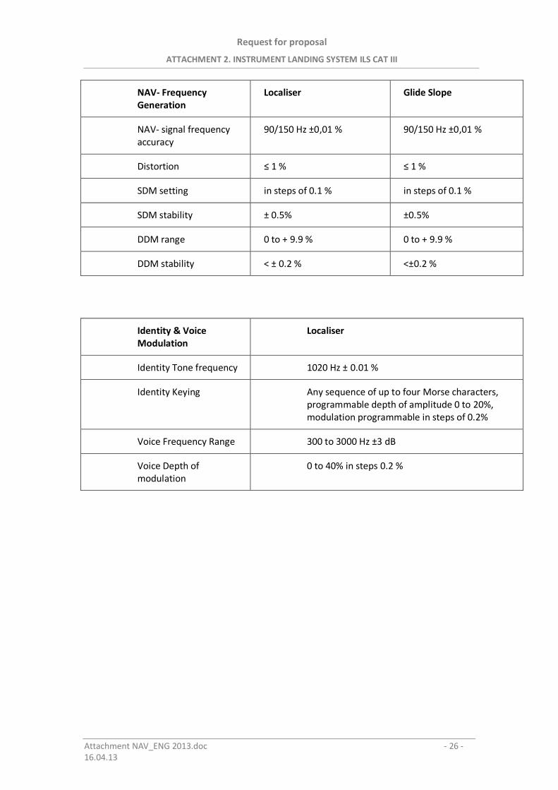
Request for proposal
ATTACHMENT 2. INSTRUMENT LANDING SYSTEM ILS CAT III
Attachment NAV_ENG 2013.doc - 26 -16.04.13
NAV- FrequencyGeneration
Localiser Glide Slope
NAV- signal frequencyaccuracy
90/150 Hz ±0,01 % 90/150 Hz ±0,01 %
Distortion 1 % 1 %
SDM setting in steps of 0.1 % in steps of 0.1 %
SDM stability ± 0.5% ±0.5%
DDM range 0 to + 9.9 % 0 to + 9.9 %
DDM stability < ± 0.2 % <±0.2 %
Identity & VoiceModulation
Localiser
Identity Tone frequency 1020 Hz ± 0.01 %
Identity Keying Any sequence of up to four Morse characters,programmable depth of amplitude 0 to 20%,modulation programmable in steps of 0.2%
Voice Frequency Range 300 to 3000 Hz ±3 dB
Voice Depth ofmodulation
0 to 40% in steps 0.2 %
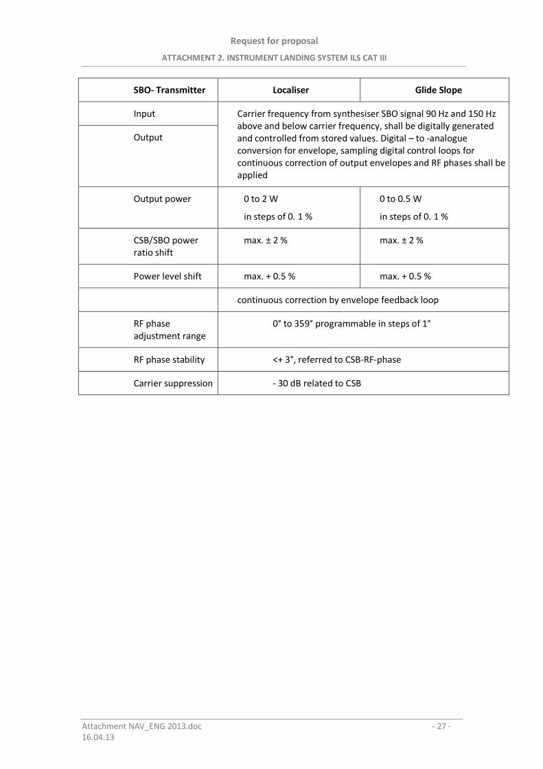
Request for proposal
ATTACHMENT 2. INSTRUMENT LANDING SYSTEM ILS CAT III
Attachment NAV_ENG 2013.doc - 27 -16.04.13
SBO- Transmitter Localiser Glide Slope
Input Carrier frequency from synthesiser SBO signal 90 Hz and 150 Hzabove and below carrier frequency, shall be digitally generatedand controlled from stored values. Digital – to -analogueconversion for envelope, sampling digital control loops forcontinuous correction of output envelopes and RF phases shall beapplied
Output
Output power 0 to 2 W
in steps of 0. 1 %
0 to 0.5 W
in steps of 0. 1 %
CSB/SBO powerratio shift
max. ± 2 % max. ± 2 %
Power level shift max. + 0.5 % max. + 0.5 %
continuous correction by envelope feedback loop
RF phaseadjustment range
0° to 359° programmable in steps of 1°
RF phase stability <+ 3°, referred to CSB-RF-phase
Carrier suppression - 30 dB related to CSB
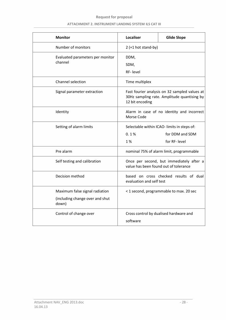
Request for proposal
ATTACHMENT 2. INSTRUMENT LANDING SYSTEM ILS CAT III
Attachment NAV_ENG 2013.doc - 28 -16.04.13
Monitor Localiser Glide Slope
Number of monitors 2 (+1 hot stand-by)
Evaluated parameters per monitorchannel
DDM,
SDM,
RF- level
Channel selection Time multiplex
Signal parameter extraction Fast fourier analysis on 32 sampled values at30Hz sampling rate. Amplitude quantising by12 bit encoding
Identity Alarm in case of no identity and incorrectMorse Code
Setting of alarm limits Selectable within ICAO- limits in steps of:
0. 1 % for DDM and SDM
1 % for RF- level
Pre alarm nominal 75% of alarm limit, programmable
Self testing and calibration Once per second, but immediately after avalue has been found out of tolerance
Decision method based on cross checked results of dualevaluation and self test
Maximum false signal radiation
(including change over and shutdown)
< 1 second, programmable to max. 20 sec
Control of change over Cross control by dualised hardware and
software
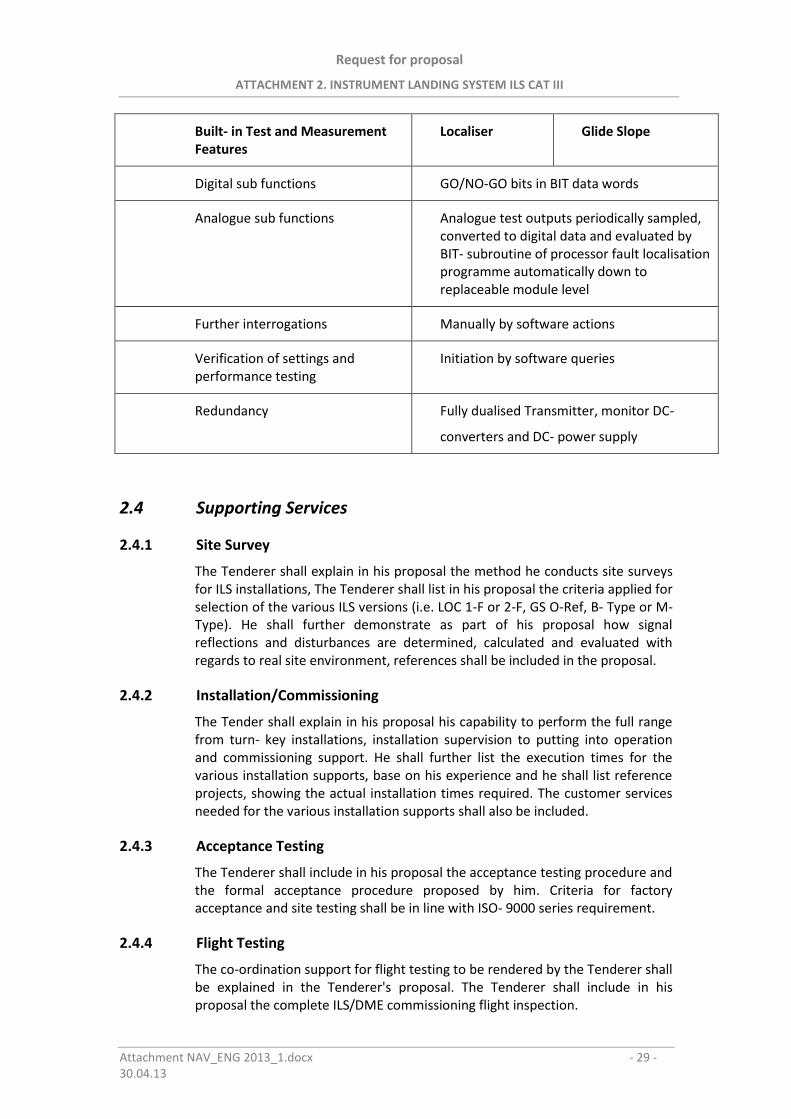
Request for proposal
ATTACHMENT 2. INSTRUMENT LANDING SYSTEM ILS CAT III
Attachment NAV_ENG 2013_1.docx - 29 - 30.04.13
Built- in Test and Measurement Features
Localiser Glide Slope
Digital sub functions GO/NO-GO bits in BIT data words
Analogue sub functions Analogue test outputs periodically sampled, converted to digital data and evaluated by BIT- subroutine of processor fault localisation programme automatically down to replaceable module level
Further interrogations Manually by software actions
Verification of settings and performance testing
Initiation by software queries
Redundancy Fully dualised Transmitter, monitor DC-
converters and DC- power supply
2.4 Supporting Services
2.4.1 Site Survey
The Tenderer shall explain in his proposal the method he conducts site surveys for ILS installations, The Tenderer shall list in his proposal the criteria applied for selection of the various ILS versions (i.e. LOC 1-F or 2-F, GS O-Ref, B- Type or M- Type). He shall further demonstrate as part of his proposal how signal reflections and disturbances are determined, calculated and evaluated with regards to real site environment, references shall be included in the proposal.
2.4.2 Installation/Commissioning
The Tender shall explain in his proposal his capability to perform the full range from turn- key installations, installation supervision to putting into operation and commissioning support. He shall further list the execution times for the various installation supports, base on his experience and he shall list reference projects, showing the actual installation times required. The customer services needed for the various installation supports shall also be included.
2.4.3 Acceptance Testing
The Tenderer shall include in his proposal the acceptance testing procedure and the formal acceptance procedure proposed by him. Criteria for factory acceptance and site testing shall be in line with ISO- 9000 series requirement.
2.4.4 Flight Testing
The co-ordination support for flight testing to be rendered by the Tenderer shall be explained in the Tenderer's proposal. The Tenderer shall include in his proposal the complete ILS/DME commissioning flight inspection.
Request for proposal
ATTACHMENT 2. INSTRUMENT LANDING SYSTEM ILS CAT III
Attachment NAV_ENG 2013_1.docx - 30 - 30.04.13
2.4.5 Technical Manuals
Technical documentation shall comply with ISO- 9000 series criteria. The technical manuals shall cover maintenance and field repair, including parts break down to the lowest replaceable item. The manuals shall also include as- built documentation, system interfaces and preventive maintenance instructions. The Tenderer shall list in his proposal a summary of documentation he intends to deliver as part of the project.
2.4.6 Maintenance Philosophy/ Spare Parts/ Test Equipment
The Tenderer shall explain in detail the operation, maintenance and repair philosophy, the equipment design has been based on. A spare parts and all maintenance required test equipment list (with itemised prices) matching with the philosophy shall be included in the Tenderer's proposal.
2.4.7 After sales Service
The Tenderer shall include the scope of after sales services available at his premises to solve customer problems during equipment life time.
2.4.8 Configuration Control
Configuration control shall be in line with ISO- 9000 series procedures. The Tenderer is required to describe in brief terms the method and procedures executed by his company.
Request for proposal
ATTACHMENT 3. DISTANCE MEASURING EQUIPMENT (DME)
Attachment NAV_ENG 2013.doc - 31 -16.04.13
3. PIELIKUMS / ATTACHMENT 3
Att lumu m r šanas iek rta (DME)
Distance Measuring Equipment (DME)
Request for proposal
ATTACHMENT 3. DISTANCE MEASURING EQUIPMENT (DME)
Attachment NAV_ENG 2013.doc - 32 -16.04.13
3. Distance Measuring Equipment (DME)
3.1 Scope
3.1.1 DME according ICAO Annex 10
This Specification covers all items required to implement an DME in terms ofthe relevant ICAO- Specifications, listed as item 2:
3.1.2 Basic Versions
The DME equipment shall be available in a lower power version - 100 W solid-state DME to be installed in co-location with ILS.
3.1.3 Auxiliary Services,
such as:
Mains- and Battery Power Supply
Signalling line interfaces
Shelters
Frame work, masts and poles
RF- cabling
are specified in brief terms.
3.1.4 References
The Tenderer is requested to make proof in his proposal to manufacture at leastDME, ILS, and DVOR equipment in his own premises and shall includereferences on worldwide installations performed.
3.2 Standards
The following Standards shall be applicable in their latest edition, includingthe latest amendments and additions, in all respects:
3.2.1 Standards of General Application
International Civil Aviation Organisation (ICAO) - Annexes, Documents andManuals
Eurocae MPS Ed. 57, standard 1 as applicable;
Comité Consultatif International Télégraphique et Téléphonique (CCITT)
Comité Consultatif International Radio (CCIR)
International Standardisation Organisation (ISO)
International Electrotechnical Commission (IEC)
International Colour Coding (ICC)
Request for proposal
ATTACHMENT 3. DISTANCE MEASURING EQUIPMENT (DME)
Attachment NAV_ENG 2013.doc - 33 -16.04.13
Euro- Norm (EN) or equivalent
Deutsche Industrie- Norm (DIN) or equivalent
Verband Deutscher Elektroingenieure (VDE) or equivalent
3.2.2 Standards of Special Application
Note: The thereafter mentioned Standards shall be met for the DMEEquipment Performance Requirements
3.2.2.1 ICAO- Annex 10, Volume 1, Part 1
Chapter 3, Section 3.5: Specification for DME
Attachment C to Part 1: Section 1 and 2- Material concerning DMEinstallations
Attachment C to Part : Section 8- Material concerning power supply switch over times
Attachment F to Part 1: Guidance material concerning reliability andavailability of radio communications andnavigation aids
3.2.2.2 ICAO- Annex 10, Volume 1, Part 2
Chapter 4, Section 4.2.- (Frequency-) Utilisation in the band 108- 117,995MHz
3.2.2.3 ICAO- Annex 14, Volume 1
Chapter 4, Section 4. 1: Obstacle limitation surfaces
3.2.2.4 ICAO- DOC 8071, Volume 11
Manual on Testing of Radio Navigation Aids, DME (ILS)
3.3 Equipment Requirement
The equipment proposed by the Tenderer shall comply with the Requirementlisted below. The compliance shall be supported by a point- to - pointstatement to be included in the Tenderer's proposal.
The DME shall consist of a 100W ground beacon housed in a 19' cabinet withtwo transponder and a dual microprocessor-controlled monitoring system withbuilt-in test equipment.
The DME shall be compatible with DME/P airborne interrogators for IAM only. Itshall operate as a COLOCATED with with ILS.
3.3.1 General Requirement
3.3.1.1 Electrical
3.3.1.1.1 Input Voltage
The AC- input voltage shall be:
Request for proposal
ATTACHMENT 3. DISTANCE MEASURING EQUIPMENT (DME)
Attachment NAV_ENG 2013.doc - 34 -16.04.13
230 Volts or 115 Volts nominal
Tolerance: +15%, -15%
Frequency: 48 to 64 Hz
3.3.1.1.2 Battery Protection
Automatic protection against battery overcharging shall be incorporated in thepower supply by means of a constant voltage circuit.
3.3.1.1.3 Stray Radiation
The power supply/charger unit shall not emit any stray radiation causinginterference to radio environment. The radio interference classification shall belisted in the Tenderer's proposal.
3.3.1.1.4 DC Supply Voltage
The D.C. output shall provide a nominal voltage below or equal 48 Volts at acurrent sufficient to operate the equipment and charge batteries at the sametime. Interdependent voltage and current regulation shall be provided.
3.3.1.1.5 Battery Charging Power Supply Configuration
Independent power supply units shall share the charging of the commonbattery set and the equipment load from a common bus bar. The arrangementshall be a dual configuration; i.e. for a dual equipment configuration 2 powersupply units shall share the load.
In case of removal or failure of one unit the equipment supply shall not beinterrupted, the remaining power supply unit shall still be capable to supply thedual equipment, the battery charging period shall be increased, only. Thecharging time (from 10%-90% battery capacity) shall not exceed:
10 hours for full power supply configuration
36 hours for single power supply configuration
3.3.1.2 Mechanical
3.3.1.2.1 Configuration
The electronic equipment shall be mounted in a 19" cabinet installed in ashelter. The frame work shall be of galvanised steel or anodised aluminium.
3.3.1.2.2 Modular Construction
For rapid replacement of units, the cabinet shall contain equipment carriers, inwhich individual plug in units and modules shall be inserted.
Drawers will not be accepted.
All the plug-in units and modules (including RF-modules) shall fit on slide railsand shall be removable from the front of the cabinet. Connectors shall be keyedto prevent insertion of units in the wrong way or into a wrong slot. Also the RF-Connectors of the modules shall be plug-in type.
3.3.1.2.3 Plug-In Units
Request for proposal
ATTACHMENT 3. DISTANCE MEASURING EQUIPMENT (DME)
Attachment NAV_ENG 2013.doc - 35 -16.04.13
3.3.1.2.3.1 Printed Circuit Boards
Printed circuit boards shall be used exclusively, also for inter wiring betweencircuits inside of plug-in units (printed mother boards). For reliability reasonsprinted mother boards shall also be used for cabinet and sub-assembly interwiring.
3.3.1.2.3.2 Coatings
Printed circuits shall be coated by a photo solder- resistant material in order toincrease the electrical resistance of the surface, and to decrease the surgingeffect of moisture and fungus on unprotected insulating surfaces.
The printed circuit board coating shall permit the replacement of componentsby soldering techniques without destroying the coating or the board surface.
3.3.1.2.3.3 Controls
In order to avoid ware and tare, no mechanically operating control elementsshall be accepted for direct signal adjustment. There shall be no potentiometersin the direct path of signal generation. The number of potentiometers shall belimited to dc- alignments.
In case of variable inputs, potentiometers shall be located on the front of theboard, as to permit setting without removing the board or needing a cardextender. Push buttons for input/output control and men/machine dialogueshall be sealed and protected against environmental effects.
3.3.1.2.3.4 Radio-Frequency Connections
RF cable connections within the electronic equipment shall be effected bymeans of coaxial connectors, throughout. RF cabling and interconnectionsbetween plug-in units and modules shall be located at the rear of the cabinet orsubrack by plug-in type connectors for the RF-modules. RF connections to thetransmitting antenna system shall be accessible on RF output connectorslocated on a separate panel inside the cabinet.
3.3.1.2.4 Wiring
Inter wiring of units within subassemblies shall be made via mother boards(printed circuits).
3.3.1.2.5 Ventilation
Cooling inside the cabinet shall be effected by convection exclusively and shallassure all components to operate well within their individual temperatureratings within the specified equipment ambient temperature range. Cooling byfans is not accepted. Heat sinks for power components and power circuits shallbe separated from low-power circuits to avoid unnecessary heat stress tolow-power circuits.
3.3.1.2.6 Shelter
Equipment shelters shall be compact and completely fitted in a way, that plug-in units and modules need to be inserted and exterior cabling have to beconnected to the respective distribution panels to assure a short installationtime on site. Shelters shall be light-weight and shall be designed to serve as aself-supporting container for transportation. Shelter material shall be noncorrosive.
Request for proposal
ATTACHMENT 3. DISTANCE MEASURING EQUIPMENT (DME)
Attachment NAV_ENG 2013.doc - 36 -16.04.13
Wall and ceiling elements shall be sandwich panels made of 1,2 mm thickAlMgSi sheeting on the inner and outer side. Between the two sheets thermalinsulation of 40 mm thick polyurethane hard-foam shall be provided. Thedimensions of the shelter shall be according to container standards, the lengthshall be at least 10 feet. The shelter shall be complete with all electricalinstallation, power distributors and signal and RF- distribution boxes. A built-inbattery compartment shall be provided. For air conditioning equipment,respective openings and supports shall be provided. The outside sheltersurfaces shall be coated with warning paint acc. to RAL 2002. Foundationdrawings with static calculation shall be provided after contract award.
3.3.1.3 Environmental Requirements
3.3.1.3.1 Windage
The DME antenna structures shall withstand wind velocities up to 160 km/h foroperation (survival 200 km/h, survival 144 km/h with 1.5cm ice load).
3.3.1.3.2 Ice Loading
Ice loads up to 5cm thickness shall not cause any damage to shelters andantenna structures.
3.3.1.3.3 Antenna Cover
Antenna elements shall be protected by glassfiber- reinforced polyester covers
3.3.1.3.4 Indoor Temperature
Indoor equipment shall operate within their specifications:
Ambient temperature -10°C to + 55°C
Relative humidity <95% in the range of –10°C to +35°C
<60% in the range of + 35°C to 55°C
3.3.1.3.5 Outdoor Temperature
Outdoor equipment and material shall withstand without any damage ordeformation:
Ambient temperature -40°C to + 70°C
Relative humidity up to 100%
3.3.1.3.6 Environmental Requirements
Outdoor elements, structures, shelters and others shall be designed andconstructed to withstand site typical effects as salt, rain, hail, thunderstorms,attacks of small to medium animals (e.g. dogs, rabbits), without damage ornoticeable deformation.
3.3.1.3.7 Temperature Variation
All equipment shall operate within their specifications (without damage ormalfunction) during Temperature variation of up to 20°C within 24 hrs.
Request for proposal
ATTACHMENT 3. DISTANCE MEASURING EQUIPMENT (DME)
Attachment NAV_ENG 2013.doc - 37 -16.04.13
3.3.1.4 System Configuration
3.3.1.4.1 Equipment Cabinet
The system concept shall be, to accommodate at least two independentequipment sections in a single 19" standard size cabinet. The power supply andcharger units shall be integrated into the electronic equipment, and shall behoused in the same cabinet. The respective safety regulations shall beobserved. Heat protections between the power supply and the electronicequipment shall prevent heat dissipation from penetrating the electronic part.
3.3.1.4.2 Monitoring
The monitoring system shall be modular and shall allow alarm thresholdsettings by Portable Maintenance Data Terminal (PMDT – Laptop) entry only.
3.3.1.5 Quality Assurance
3.3.1.5.1 Certifications
The Tenderer shall be an ISO 9000 certified manufacturer. The production ofthe proposed NAVAIDS shall fall under the ISO 9000 certificate.
Hardware and software design, quality assurance in the production process, aswell as documentation shall be in line with ISO 9000 series.
3.3.1.5.2 Burn-In
Components and sub units shall undergo "burn- in" tests during production.
The complete system shall be subject to "burn- in" testing at a temperature of50°C at least 48 hrs.
3.3.1.6 Main Features of the Equipment
It shall comply with the ICAO specifications in Annex 10, 5th ed. July 2006 andEurocae MPS Ed. 57, standard 1 as applicable; also refer to the FAA – E-2721/13specifications.
It shall be housed in a single 19" cabinet (standard height 1730 mm, width 580mm, depth 61Omm.
It shall be powered both from mains and from standard 48 V batteries, withbuilt - in battery charger as an option.
The equipment shall have the capability to be powered from a collocated ILSbeacon with +48 V DC.
It shall be fully dual, being composed of two 100W transponders and twomicroprocessor-controlled monitoring systems.
It shall be completely modular.
Its distance information shall be accurate: up to ± 15 m.
Its output pulse shape shall be digitally controlled by a microprocessor to thetransponder itself.
Its monitoring shall be dualized and microprocessor-controlled.
Request for proposal
ATTACHMENT 3. DISTANCE MEASURING EQUIPMENT (DME)
Attachment NAV_ENG 2013.doc - 38 -16.04.13
It shall automatically provide ICAO performance checks at programmableintervals and results shall be stored/displayed/printed at operator's choice.
It shall be capable of executing a resident diagnostic program to help theoperator in locating a failure.
It shall be controlled through a Personal Computer (PC) at beacon site, whichcan be duplicated at remote site; the PC can also be a portable unit to beconnected only when required for maintenance reasons.
It shall be possible to connect it to a Remote Control and Monitoring NetworkSystem, for interfacing and controlling different navaids facilities.
3.3.2 Engineering
MODULARITY: all circuits shall be divided into functional modules, all modulesshall be accessible from the front of the equipment.
INTERCONNECTIONS: extensive use shall be made of printed board back planes,flat cables and semi-rigid coaxial cables.
IDENTIFICATIONS: all modules shall be easily recognizable by their P/N and athree-letter code permanently marked on easily readable surfaces. All modules,cables and connectors shall be marked and keyed to prevent incorrectconnection.
COOLING: no blowers shall be required to remove heat from the equipment,extensive use shall be made of aluminium extruded heat sinks
PRINTED BOARDS: two-or multilayer printed boards with plated-through holesshall be used throughout the equipment; high frequency circuits shall beimplemented in microstrip technique.
RF SHIELDING: all RF circuits shall be accurately shielded in casting or extrusionboxes.
CORROSION: protection against corrosion and fungus shall be obtained bymeans of suitable materials, finishes and coating.
SAFETY: the equipment shall be designed in order to be intrinsically safe for theuser. No dangerous voltages except mains shall be used. All modules or places,where a dangerous voltage may be accessible, shall be firmly protected bycovers not removable without use of tools and clearly marked with warningreadouts.
PROTECTIVE DEVICES: special protective circuits shall be built-in in order toensure that any failure in the equipment does not cause further damage toother parts or components.
COMPONENTS: only high-quality components shall be used, in order to meetthe reliability requirements.
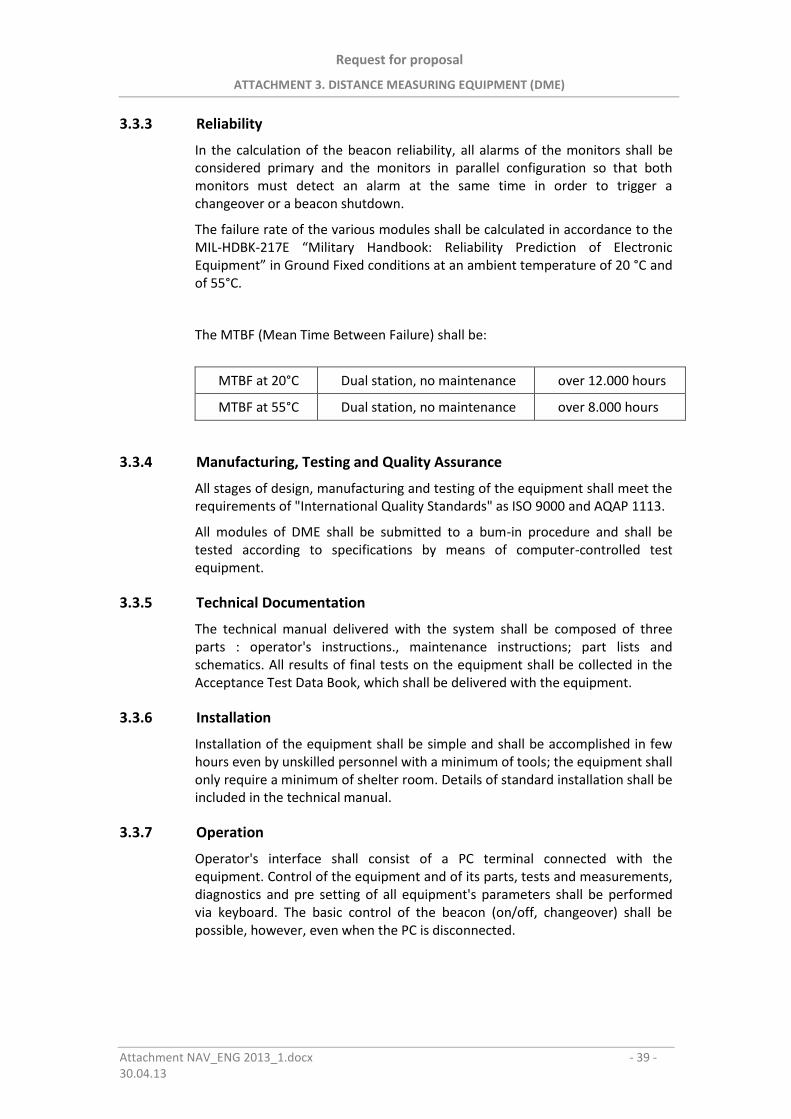
Request for proposal
ATTACHMENT 3. DISTANCE MEASURING EQUIPMENT (DME)
Attachment NAV_ENG 2013_1.docx - 39 - 30.04.13
3.3.3 Reliability
In the calculation of the beacon reliability, all alarms of the monitors shall be considered primary and the monitors in parallel configuration so that both monitors must detect an alarm at the same time in order to trigger a changeover or a beacon shutdown.
The failure rate of the various modules shall be calculated in accordance to the MIL-HDBK-217E “Military Handbook: Reliability Prediction of Electronic Equipment” in Ground Fixed conditions at an ambient temperature of 20 °C and of 55°C.
The MTBF (Mean Time Between Failure) shall be:
MTBF at 20°C Dual station, no maintenance over 12.000 hours
MTBF at 55°C Dual station, no maintenance over 8.000 hours
3.3.4 Manufacturing, Testing and Quality Assurance
All stages of design, manufacturing and testing of the equipment shall meet the requirements of "International Quality Standards" as ISO 9000 and AQAP 1113.
All modules of DME shall be submitted to a bum-in procedure and shall be tested according to specifications by means of computer-controlled test equipment.
3.3.5 Technical Documentation
The technical manual delivered with the system shall be composed of three parts : operator's instructions., maintenance instructions; part lists and schematics. All results of final tests on the equipment shall be collected in the Acceptance Test Data Book, which shall be delivered with the equipment.
3.3.6 Installation
Installation of the equipment shall be simple and shall be accomplished in few hours even by unskilled personnel with a minimum of tools; the equipment shall only require a minimum of shelter room. Details of standard installation shall be included in the technical manual.
3.3.7 Operation
Operator's interface shall consist of a PC terminal connected with the equipment. Control of the equipment and of its parts, tests and measurements, diagnostics and pre setting of all equipment's parameters shall be performed via keyboard. The basic control of the beacon (on/off, changeover) shall be possible, however, even when the PC is disconnected.
Request for proposal
ATTACHMENT 3. DISTANCE MEASURING EQUIPMENT (DME)
Attachment NAV_ENG 2013.doc - 40 -16.04.13
3.3.8 Maintenance
Automatic routine check of beacon performances according to ICAOspecifications shall be obtained through the control system both from site andfrom the remote control location, and shall be programmed to be automaticallyperformed and recorded at fixed intervals. In both cases, the results shall beprinted on request.
Troubleshooting and repair shall be based on the following concepts :
on-equipment on-site maintenance involves fault isolation down to modulelevel and replacement of the faulty module. It shall be performed bylow-level repairman by means of the built-in diagnostic capability of themonitoring system; in most cases the failure shall be traced down tomodule level even from remote site. Repair shall require standard toolsonly.
Mean Time to Repair (MTTR) shall be below 25 minutes; no single repair shallexceed 90 minutes.
Off-equipment off-site maintenance shall involve troubleshooting andrepair on the faulty modules down to component level. A higher skill levelshall be required and work shall be executed in a suitable equippedTechnical Center.
3.4 FUNCTIONAL Requirements
3.4.1 General
The DME shall consist of the following main parts.
In/Out system
control system
monitoring system
transponder system
RF path
external connection interface system
power supply system
The DME In/Out system shall be totally modular, it shall be able to meet anytype of requirement that may arise in an installation; this system shall make itpossible to control and monitor the beacon using a Personal Computer and/orControl Panel.
The main parts of the In/Out system shall be
Control & Status Board
Personal Computer

Request for proposal
ATTACHMENT 3. DISTANCE MEASURING EQUIPMENT (DME)
Attachment NAV_ENG 2013.doc - 41 -16.04.13
At the local site, the beacon-operator interface shall consist of:
Control Panel
Personal Computer (optional), which allows the operator to completelycontrol and monitor the beacon
The In/Out system shall be handled by the Control & Status Board unit whichshall control and handle the communication with remote monitoring andcontrol sites which takes place through communication line(s).
The I/O devices which interface the operator in a remote site shall be a RemoteMonitoring and Maintenance System with Personal Computer.
The remote Personal Computer shall allow the operator to completely controland monitor the beacon. It shall perform the same operations of the local sitePersonal Computer.
The Control Panel shall consist of three sections: the first section carrying thebeacon operating status LED´s and the buzzer (engaged when the beacon shut-down occurs), the second section carrying the beacon commands, and finallythe third section carrying additional indications.
The interface terminal with the operator used for equipment control,monitoring and maintenance shall consist of an IBM compatible PersonalComputer.
At the local site the communication between the PC and the equipment shalltake place through a serial RS-232C or USB or LAN connection by means of theControl & Status Board unit.
The PC shall communicate directly with the local site equipment through acommunication line by means of a modem or through a Remote Monitoring andMaintenance System. The RMMS-System shall communicate with the local siteby means of a communication line and the PC shall be linked to the RMMSthrough an RS-232C or USB or LAN interface.
3.4.2 Control and Monitor System
The Control and Monitor System of DME shall be designed to achieve the goalsof maximum integrity, versatility and performance. It shall be composed of two(dualised) monitor boards, each equipped with a microprocessor.
Each monitor shall be a complete programmable DME instrumentation set initself composed by an interrogator and a Signal Analyzer capable to perform alltests and checks required for routine maintenance and for automaticdiagnostics.
The transponder control shall take actual control of the beacon by means oftwo independent microprocessors with dualized data buses, connected with theother circuits through suitable interface cards.
The structure shall be conceived such as to avoid that any single failurewhatever impair the system capability of providing correct DME service toaircraft.
Request for proposal
ATTACHMENT 3. DISTANCE MEASURING EQUIPMENT (DME)
Attachment NAV_ENG 2013.doc - 42 -16.04.13
Multiple failures in dual units, or failures whose origin cannot be assessed withcertainty, shall bring to equipment shut down.
The microprocessors of the dualized monitor system and of both transpondersshall also communicate by means of the CSB unit, with the 1/0 devices (Localand Remote) and shall provide the Operator with complete control over theequipment, fully automatic pre-setting of all operational parameters andcontinuous updating about equipment status, measurement, results etc.
The software program resident in the microprocessors shall be responsible ofthe total equipment management.
Its structure shall be shared in elementary activities; each of them dedicated toa particular task.
3.4.2.1 Routine Check
When the ROUTINE CHECK is launched the monitors shall perform a series ofmeasurements on all parameters relating to the transponder connected to theantenna, to the dummy load or to the monitors, depending on which one wasselected by the operator. The results of these measurements shall then bedisplayed on the PC.
The measurement list shall come after the list of the main parameters preset forcorrect interpretation of the Routine Check.
These parameters shall be:
CHANNEL AND MODE
REPLY DELAY
DEAD TIME
SHORT ECHO SUPPRESSION
THRESHOLD LONG DISTANCE ECHO
SENSITIVITY N
The Number of Samples for Average calculation (NSFA) shall depend on theparameter to be measured; usually, its value ranges between 1 and 1000. Thetests that shall be selected for the transponder connected to the antenna arelisted below with the messages which shall be displayed on the screen:
PULSE SPACING: spacing between the pulses in a pair measured using the halfamplitude points on the rising edge of the two individual pulses in the pair asreference. The final result of the measurement shall be obtained by averaging100 measurements, with an accuracy of ±20ns.
PEAK POWER OUTPUT: peak power output of both the pulses making up thereply or squitter pair; the final result, shall be the average of 100 singlemeasurements, has an accuracy of +1- 0.5 dB.
TRANSMISSION RATE: transmission rate is defined as the number of pulse pairstransmitted per second (pp/s); it shall be selected to cover a range of valuesfrom 800 ± 50 pp/s up to 4800 ± 150 pp/s or from 2700 ±90 pp/s up to 4800
Request for proposal
ATTACHMENT 3. DISTANCE MEASURING EQUIPMENT (DME)
Attachment NAV_ENG 2013.doc - 43 -16.04.13
±150 pp/s. The final result, obtained by averaging 10 single measurements, hasan accuracy of ±20 pp/s.
PEAK POWER DROOP: maximum power output droop with respect to theaverage power value the result shall be obtained by averaging the results of1000 measurements performed on the transmitted pulses.
REPLY EFFICIENCY: reply efficiency defined as the percentage ratio between thenumber of interrogation pulse pairs and the number of reply interrogation pulsepairs. The measurement shall be performed by counting the replies to 50interrogations per second with an interrogation level of 6 dB above thesensitivity threshold; the final result shall be obtained by averaging 100 singlemeasurements, with an accuracy of ± 2%.
TRANSMITTER FREQUENCY: the value of the transmission frequency relating tothe set channel shall be measured by a counter; the final result, shall beobtained by averaging 10 single measurements, with an accuracy of ±50 ppm(parts per million).
PULSE SHAPE: the shape of the individual pulses making up the replypair shall be obtained by measuring the rise time, decay time andduration; the result shall be obtained by averaging the results of 50 singlemeasurements.
REPLY DELAY VARIATION WITH LEVEL: reply delay variation in relation to theinterrogation level, where the reply delay is the interval of time between theinterrogation pulses, generated by the interrogator (MIN), and the replies. Themeasurements shall be performed for an interrogating level of -10 dBm, -30dBm, -50 dBm, -71 dBm and 3 dB above the sensitivity threshold set for thereceiver, the final result shall be obtained by averaging 100 single interrogationswith an accuracy of ±20 ns.
SENSITIVITY N: receiver sensitivity shall be obtained by measuring the replyefficiency with an interrogation level of ±3 dB, ±2 dB and ±1 dB above andbelow the sensitivity threshold set for the receiver; the final result shall beobtained by averaging the results of 100 single measurements.
BANDWIDTH: bandwidth shall be obtained by measuring the reply efficiency ata frequency which differs from the nominal frequency of the operating channelby ±200 kHz and by using the pulses with an interrogation level of 3 dB abovethe sensitivity threshold set for the receiver; the final result shall be obtained byaveraging the results of 100 single measurements.
ADJACENT CHANNEL REJECTION: adjacent channel rejection shall beobtained by measuring the reply efficiency at a frequency which differsfrom the nominal frequency of the operating channel by ±900 kHz, usingpulses with an interrogation level of -10 dBm. the final result shall beobtained by averaging the results of 100 single measurements.
DECODER: the correctness of the decoding operations performed by theprocessor module shall be ascertained by measuring the reply efficiency forpulse pairs with a spacing that differs from the nominal value by ±1 µs with aninterrogating level 1 dB above the sensitivity threshold set for the receiver, thereply efficiency for pulse pairs with spacing that differs from the nominal valueby ±2 µs with an interrogating level of -10 dBm and the reply efficiency for
Request for proposal
ATTACHMENT 3. DISTANCE MEASURING EQUIPMENT (DME)
Attachment NAV_ENG 2013.doc - 44 -16.04.13
individual pulses with an interrogating level of -10 dBm the final result shall beobtained by averaging the results of 100 single measurements.
DEAD TIME: dead time shall be obtained by measuring the reply efficiency forthe interrogations which fall 2 µs before and 14 µs after the end of the deadtime activated by a previous interrogation with an interrogation level of -70dBm. The final result shall be obtained by averaging the results of 100 singlemeasurements.
RECOVERY TIME: recovery time shall be obtained by measuring the replyefficiency relating to an interrogation, with an interrogation level 1 dB abovethe sensitivity threshold set for the receiver, that falls 9 µs after a single pulseinterrogation, with an interrogating level 60 dB above the sensitivity threshold.The results of this test shall not be significant if the short echo suppressioncircuits are activated. The final result shall be obtained by averaging the resultsof 100 single measurements.
ECHO SUPPRESSION: echo suppression shall be estimated for both long andshort echo suppression. To check that the long echo suppression circuitsfunction correctly, an interrogation with a level 3 dB above the anti-echoactivation threshold set shall be used to trigger the anti-echo circuits and thereply efficiency (NSFA of the measurement equal to 1) shall be measured in thefollowing three ways:
with interrogations that simulate the presence of echo pulses with aninterrogation level 10 dB above the anti-echo circuit activation thresholdset and a delay with respect to the trigger equal to: (Nominal InterrogationSpacing)+ (Anti-echo Duration)- 6 µs. The final result shall be obtained byaveraging the results of 100 single measurements.
with interrogations that simulate the presence of echo pulses with aninterrogation level 2 dB greater than the anti echo activation threshold setand delay, with respect to the trigger, which is the same as the delayabove.
with interrogations that simulate the presence of echo pulses with aninterrogation level 2 dB greater than the anti-echo circuits activationthreshold set, and with a delay, with respect to the trigger, equal to(Nominal Interrogation Spacing)+ (Anti-echo Duration)+ 6 us
IDENTITY CODE: identity code set for the beacon expressed in Morse code.,NSFA of the measurement equal to one.
IDENTITY TIMING: identity code timing shall be obtained by measuring theduration of the dots, dashes and spaces in the character, the interval betweentwo characters, the repetition rate and the code period (1350 Hz frequency)between two pairs which identify the code.
3.4.2.2 Presetting
All equipment functional parameters shall be stored in the controllers EEPROMAlmost all parameters shall have default values, with the exception of thefollowing ones:
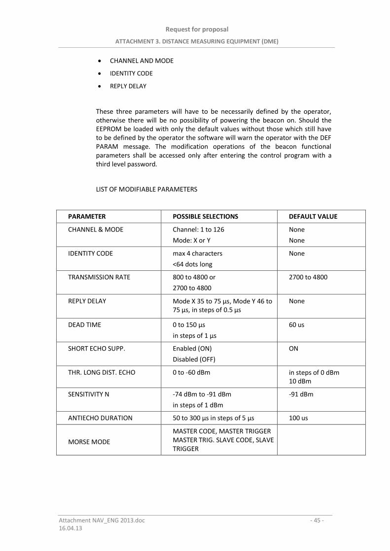
Request for proposal
ATTACHMENT 3. DISTANCE MEASURING EQUIPMENT (DME)
Attachment NAV_ENG 2013.doc - 45 -16.04.13
CHANNEL AND MODE
IDENTITY CODE
REPLY DELAY
These three parameters will have to be necessarily defined by the operator,otherwise there will be no possibility of powering the beacon on. Should theEEPROM be loaded with only the default values without those which still haveto be defined by the operator the software will warn the operator with the DEFPARAM message. The modification operations of the beacon functionalparameters shall be accessed only after entering the control program with athird level password.
LIST OF MODIFIABLE PARAMETERS
PARAMETER POSSIBLE SELECTIONS DEFAULT VALUE
CHANNEL & MODE Channel: 1 to 126
Mode: X or Y
None
None
IDENTITY CODE max 4 characters
<64 dots long
None
TRANSMISSION RATE 800 to 4800 or
2700 to 4800
2700 to 4800
REPLY DELAY Mode X 35 to 75 µs, Mode Y 46 to75 µs, in steps of 0.5 µs
None
DEAD TIME 0 to 150 µs
in steps of 1 µs
60 us
SHORT ECHO SUPP. Enabled (ON)
Disabled (OFF)
ON
THR. LONG DIST. ECHO 0 to -60 dBm in steps of 0 dBm10 dBm
SENSITIVITY N -74 dBm to -91 dBm
in steps of 1 dBm
-91 dBm
ANTIECHO DURATION 50 to 300 µs in steps of 5 µs 100 us
MORSE MODE
MASTER CODE, MASTER TRIGGERMASTER TRIG. SLAVE CODE, SLAVETRIGGER
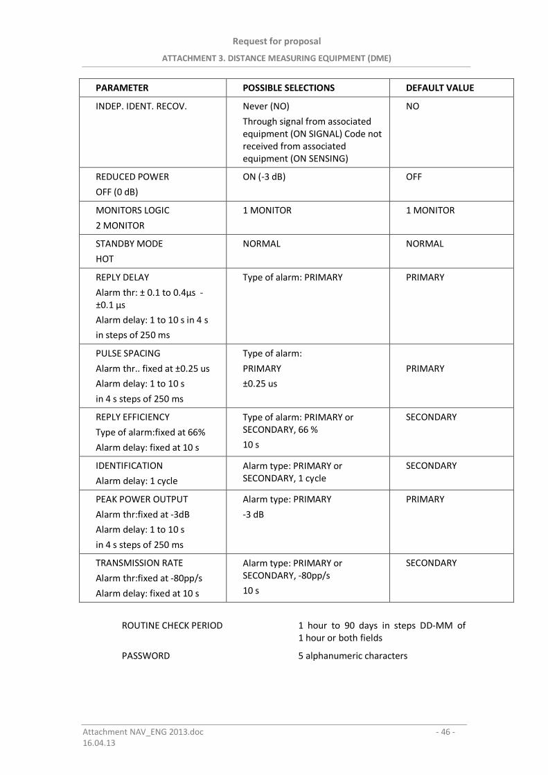
Request for proposal
ATTACHMENT 3. DISTANCE MEASURING EQUIPMENT (DME)
Attachment NAV_ENG 2013.doc - 46 -16.04.13
PARAMETER POSSIBLE SELECTIONS DEFAULT VALUE
INDEP. IDENT. RECOV. Never (NO)
Through signal from associatedequipment (ON SIGNAL) Code notreceived from associatedequipment (ON SENSING)
NO
REDUCED POWER
OFF (0 dB)
ON (-3 dB) OFF
MONITORS LOGIC
2 MONITOR
1 MONITOR 1 MONITOR
STANDBY MODE
HOT
NORMAL NORMAL
REPLY DELAY
Alarm thr: ± 0.1 to 0.4µs -±0.1 µs
Alarm delay: 1 to 10 s in 4 s
in steps of 250 ms
Type of alarm: PRIMARY PRIMARY
PULSE SPACING
Alarm thr.. fixed at ±0.25 us
Alarm delay: 1 to 10 s
in 4 s steps of 250 ms
Type of alarm:
PRIMARY
±0.25 us
PRIMARY
REPLY EFFICIENCY
Type of alarm:fixed at 66%
Alarm delay: fixed at 10 s
Type of alarm: PRIMARY orSECONDARY, 66 %
10 s
SECONDARY
IDENTIFICATION
Alarm delay: 1 cycle
Alarm type: PRIMARY orSECONDARY, 1 cycle
SECONDARY
PEAK POWER OUTPUT
Alarm thr:fixed at -3dB
Alarm delay: 1 to 10 s
in 4 s steps of 250 ms
Alarm type: PRIMARY
-3 dB
PRIMARY
TRANSMISSION RATE
Alarm thr:fixed at -80pp/s
Alarm delay: fixed at 10 s
Alarm type: PRIMARY orSECONDARY, -80pp/s
10 s
SECONDARY
ROUTINE CHECK PERIOD 1 hour to 90 days in steps DD-MM of1 hour or both fields
PASSWORD 5 alphanumeric characters
Request for proposal
ATTACHMENT 3. DISTANCE MEASURING EQUIPMENT (DME)
Attachment NAV_ENG 2013.doc - 47 -16.04.13
3.4.3 Remote Control and Monitoring System
The Remote Control Maintenance and Monitoring Network System (RMMS)shall consist of modular elements that shall allow:
to monitor and control a main equipment (for example: DME) and associatedequipment (for example: ILS), through a Personal Computer and by means ofRemote Status Indicator (RSI).
To communicate with one or more Remote Control Sites through leased anddial-up lines.
The RCMS shall be composed essentially of the following elements:
DME CSB UNIT (I/O Manager)
PERSONAL COMPUTER WITH SOFTWARE
CTU (Status Indicator for Control Tower)
RCSE (Remote Control & Status Equipment)
REMOTE PERSONAL COMPUTER
The RMMS shall be designed and manufactured in order to provide a standardmean suitable to locally and remotely control of main equipment which shall beprovided with RS-232C port or USB or LAN to transfer outside some informationand to acquire from outside some controls.
These signals, managed by a processor, shall be ruled by software inserted in alocal PC, or by PC placed in remote sites and connected to leased or dial-uplines.
Besides the above mentioned digital signals, the RMMS shall be able to manageother parallel ON/OFF (I/O) signals coming from associated (either local orremote) that can be used to operate indicators and to send commands.
The RMMS operation shall be based on the components modularity, to make iteasy to modify and implement the network in the future (Centralized RemoteControl System) and to use it through standard interfaces and procedures, inorder to control a main equipment an/or associated equipment.
The digital information exchange among the various sites (consisting ofindications and commands) shall be made on normal lines of the leased ordial-up type.
The connection through leased lines shall be of the point to point type,therefore the remote site provided with this connection shall be in directtouch with the CSB unit.
The connection of remote sites on dial-up lines shall be established by means ofthe software program that automatically shall provided to up-date in sequencethe memories of the RSI unit when an event occurs.
The up-dating of the archive of the Personal Computer shall take placeautomatically every time the PC is switched-on and the program starts, or whenthe operator enters the "control" option of the program by means of the
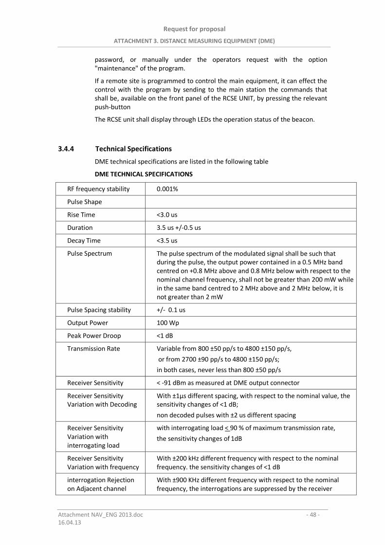
Request for proposal
ATTACHMENT 3. DISTANCE MEASURING EQUIPMENT (DME)
Attachment NAV_ENG 2013.doc - 48 -16.04.13
password, or manually under the operators request with the option"maintenance" of the program.
If a remote site is programmed to control the main equipment, it can effect thecontrol with the program by sending to the main station the commands thatshall be, available on the front panel of the RCSE UNIT, by pressing the relevantpush-button
The RCSE unit shall display through LEDs the operation status of the beacon.
3.4.4 Technical Specifications
DME technical specifications are listed in the following table
DME TECHNICAL SPECIFICATIONS
RF frequency stability 0.001%
Pulse Shape
Rise Time <3.0 us
Duration 3.5 us +/-0.5 us
Decay Time <3.5 us
Pulse Spectrum The pulse spectrum of the modulated signal shall be such thatduring the pulse, the output power contained in a 0.5 MHz bandcentred on +0.8 MHz above and 0.8 MHz below with respect to thenominal channel frequency, shall not be greater than 200 mW whilein the same band centred to 2 MHz above and 2 MHz below, it isnot greater than 2 mW
Pulse Spacing stability +/- 0.1 us
Output Power 100 Wp
Peak Power Droop <1 dB
Transmission Rate Variable from 800 ±50 pp/s to 4800 ±150 pp/s,
or from 2700 ±90 pp/s to 4800 ±150 pp/s;
in both cases, never less than 800 ±50 pp/s
Receiver Sensitivity < -91 dBm as measured at DME output connector
Receiver SensitivityVariation with Decoding
With ±1µs different spacing, with respect to the nominal value, thesensitivity changes of <1 dB;
non decoded pulses with ±2 us different spacing
Receiver SensitivityVariation withinterrogating load
with interrogating load < 90 % of maximum transmission rate,
the sensitivity changes of 1dB
Receiver SensitivityVariation with frequency
With ±200 kHz different frequency with respect to the nominalfrequency. the sensitivity changes of <1 dB
interrogation Rejectionon Adjacent channel
With ±900 KHz different frequency with respect to the nominalfrequency, the interrogations are suppressed by the receiver
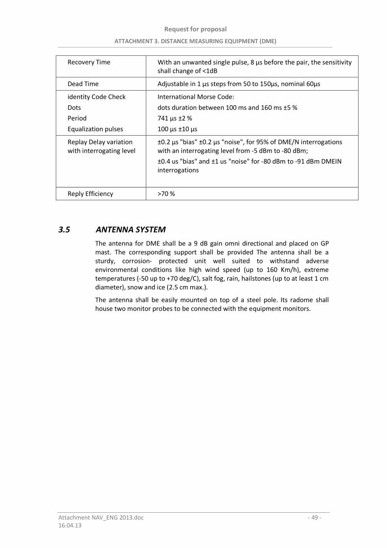
Request for proposal
ATTACHMENT 3. DISTANCE MEASURING EQUIPMENT (DME)
Attachment NAV_ENG 2013.doc - 49 -16.04.13
Recovery Time With an unwanted single pulse, 8 µs before the pair, the sensitivityshall change of <1dB
Dead Time Adjustable in 1 µs steps from 50 to 150µs, nominal 60µs
identity Code Check
Dots
Period
Equalization pulses
International Morse Code:
dots duration between 100 ms and 160 ms ±5 %
741 µs ±2 %
100 µs ±10 µs
Replay Delay variationwith interrogating level
±0.2 µs "bias" ±0.2 µs "noise", for 95% of DME/N interrogationswith an interrogating level from -5 dBm to -80 dBm;
±0.4 us "bias" and ±1 us "noise" for -80 dBm to -91 dBm DMEINinterrogations
Reply Efficiency >70 %
3.5 ANTENNA SYSTEM
The antenna for DME shall be a 9 dB gain omni directional and placed on GPmast. The corresponding support shall be provided The antenna shall be asturdy, corrosion- protected unit well suited to withstand adverseenvironmental conditions like high wind speed (up to 160 Km/h), extremetemperatures (-50 up to +70 deg/C), salt fog, rain, hailstones (up to at least 1 cmdiameter), snow and ice (2.5 cm max.).
The antenna shall be easily mounted on top of a steel pole. Its radome shallhouse two monitor probes to be connected with the equipment monitors.
Request for proposal
ATTACHMENT 4. VCCS
Attachment NAV_ENG 2013.doc - 50 -16.04.13
4. PIELIKUMS / ATTACHMENT 4
Balss komunik ciju un kontroles VCCS
Communication and Control System VCCS
Request for proposal
ATTACHMENT 4. VCCS
Attachment NAV_ENG 2013.doc - 51 -16.04.13
4. VOICE COMMUNICATION SYSTEM
4.1 Technical Specifications requested for VCCS
4.1.1 System Configuration (Tentative)
4.1.1.1 VCCS network shall provide flexibility for sharing of radio and telephoneresources.
4.1.1.2 The VCCS system shall have the following configuration:
4.1.1.2.1 Six (6) operator positions, with capacity for future upgrade to twenty (20)operators
4.1.1.2.2 Eight (8) radio channels, with capacity for future upgrade to twenty (20)channels
4.1.1.2.3 Twenty (20) telephone channels, with capacity for future upgrade to forty (40)channels
4.1.2 System Management & Maintenance
4.1.2.1 The VCCS shall provide non-intrusive maintenance capabilities, so that thesystem can be serviced and managed without impacting day-to-day operations,including:
4.1.2.1.1 Easy interconnection
4.1.2.1.2 Automatic system configuration on start-up
4.1.2.1.3 Diagnostics capability: Automatic fault detection and isolation provided byBuilt-In-Test-Equipment (BITE).
4.1.2.1.4 Troubleshooting to LRU capability: Failure of a component or module isautomatically identified by front panel LEDs and the software maintenanceapplication.
4.1.2.1.5 Hot swapping capability: Central equipment modules can be replaced withoutaffecting the operation of the system.
4.1.2.2 System Administration and Reconfiguration Terminal
4.1.2.2.1 The System Administration and Reconfiguration Terminal shall provide the toolsto effectively perform maintenance, including:
4.1.2.2.1.1 Create or alter system database files
4.1.2.2.1.2 Upload software to the switching node
4.1.2.2.1.3 Track system diagnostics
Request for proposal
ATTACHMENT 4. VCCS
Attachment NAV_ENG 2013.doc - 52 -16.04.13
4.1.3 Operational Capabilities
4.1.3.1 Core Tasks
4.1.3.1.1 The operators shall be able to perform core tasks such as:
4.1.3.1.1.1 Communicate over HF, VHF, UHF, telephone
4.1.3.1.1.2 Key radios using tone keying, E&M leads and relay closures
4.1.3.1.1.3 Control gain and squelch
4.1.3.1.1.4 Toggle between main and stand-by radios
4.1.3.1.1.5 Perform intercoms between positions
4.1.3.2 Advanced Operations
4.1.3.2.1 The operators shall be able to perform advanced operations by providing accessto:
4.1.3.2.1.1 Record and Playback capability (optional)
4.1.3.2.1.2 Centralized databases for individual profiles
4.1.3.2.1.3 Diagnostics
4.1.3.2.1.4 Video (optional)
4.1.3.2.1.5 Instant messaging between supervisors (optional)
4.1.3.3 System Administration
4.1.3.3.1 In addition, supervisors (or system administrators) shall be able to:
4.1.3.3.1.1 Modify the touch interface (look and feel)
4.1.3.3.1.2 View system diagnostics
4.1.3.3.1.3 Modify user profiles
4.1.3.3.1.4 Notify operators of configuration changes
4.1.3.3.1.5 Instant Message to operators
4.1.3.3.1.6 Activate or deactivate user features
4.1.3.3.1.7 Monitor up to 12 operators
4.1.4 Performance Capabilities
4.1.4.1 Automatic Fault Diagnosis and Correction
4.1.4.1.1 The VCCS shall be able to generate diagnostic messages that can be viewedwith the maintenance software, in all cases of fault detection.
4.1.4.2 Position Test
4.1.4.2.1 The operators shall be able to perform position tests and adjustments usingmanual tests that are available at the positions.
4.1.4.2.2 Tests include verifying button assignments, checking indicator functionality,testing headset and speaker operation, adjusting chime and volume settings.
Request for proposal
ATTACHMENT 4. VCCS
Attachment NAV_ENG 2013.doc - 53 -16.04.13
4.1.4.3 Reliability and Availability
4.1.4.3.1 The Mean Fault Isolation Time (MFIT) and Mean Time to Repair (MTTR) has tobe less than 20 minutes.
4.1.4.3.2 The VCCS has to be 100 percent non-blocking, and all positions have access toall system resources at all times.
4.1.4.3.3 The redundant design of the system shall provide a system availability of99.9999%.
4.1.4.4 End-to-End Delay
4.1.4.4.1 The nominal voice delay through the system shall be less than 200 milliseconds.
4.1.4.4.2 PTT response time shall be less than 25 milliseconds.
4.1.4.4.3 This time shall be measured from the instant of closure of foot switch (or otherkeying device) to the availability of PTT signal at the radio interface.
4.1.4.5 Maintainability
4.1.4.5.1 The maintenance software shall offer functions that include status display,audible alarms, logging functions, system hardware configuration, softwareupdates, diagnostics, system troubleshooting to LRU, and verify restored LRUs.
4.1.4.5.2 Automatic fault detection and isolation shall be provided by Built-In-Test-Equipment (BITE).
4.1.4.5.3 Any central equipment module shall be able to be replaced without affectingthe operation of the system.
Request for proposal
ATTACHMENT 4. VCCS
Attachment NAV_ENG 2013.doc - 54 -16.04.13
4.1.5 Functional Capabilities
4.1.5.1 The VCCS shall provide full air-to-ground and ground-to-groundcommunications capabilities coupled with flexible system maintenance andsupervisory controls.
4.1.5.2 The operator Touch Entry Device (TED) shall be built around therecommendations of ICAO Computer Human Interface (CHI) specifications.
4.1.5.3 The operation shall be based on touching the screen to activate iconsrepresenting the action to be performed.
4.1.5.4 Visual and audible alerts shall be presented to the operator confirming actionsperformed and the results on other affected positions, as appropriate.
4.1.5.5 Access to circuits, frequencies, and features shall be configurable at theMaintenance and Supervisor position.
4.1.5.6 These resource assignments shall be stored at the server as system maps(operator layout configurations) and assigned on an operator / group basis.
4.1.5.7 Upon login, the operator shall be presented with a set of available system mapsassigned to him/her.
4.1.5.8 When logged in, the operator shall be able to save his/her individualpreferences to the assigned system maps.
4.1.5.9 The function buttons of the CHI shall be able to be configured as latching ornon-latching, switching between states (such as on/off and headset /loudspeaker / mute) via single, momentary touch action or sustained touchaction.
4.1.5.10 Unique eight-character alphanumeric identifiers and icons shall label theselector’s functions (frequency, location identification, feature, etc.).
4.1.5.11 Air-to-ground features (radio-specific functions)
4.1.5.11.1 A/G channel controls
4.1.5.11.1.1 The VCCS shall provide the following A/G channel controls: TX select, RX select, TXMain/Stby, RX Main/Stby, HEADSET/SPEAKER, volume control and mute.
4.1.5.11.2 A/G headset/speaker selection
4.1.5.11.2.1 The operator shall be able to direct incoming A/G calls, to the headset or to the speaker,for each channel.
4.1.5.11.3 A/G PTT activation
4.1.5.11.3.1 Activating the PTT footswitch or hand-switch shall cause transmission on all radiochannels that are enabled to transmit.
4.1.5.11.4 A/G PTT lockout
4.1.5.11.4.1 It shall not be possible for more than one operator to transmit on a given radio circuit atany given time.
4.1.5.11.5 Broadcast feature
4.1.5.11.5.1 When enabled, the broadcast button shall select all non-emergency radio channels fortransmitting and all emergency channels for monitoring.
4.1.5.11.6 Emergency channels
Request for proposal
ATTACHMENT 4. VCCS
Attachment NAV_ENG 2013.doc - 55 -16.04.13
4.1.5.11.6.1 One or more channels shall be possible to be defined as emergency channels. On anemergency channel, the “Tx select” button shall be the “PTT” button.
4.1.5.11.7 Frequency add and drop
4.1.5.11.7.1 Operators shall be able to assign or remove channels on their own positions.
4.1.5.11.8 Main/standby Transfer (coupled or independent)
4.1.5.11.8.1 The operator shall be able to switch between main and standby receivers andtransmitters, either coupled or independent.
4.1.5.11.9 Receiver volume control
4.1.5.11.9.1 The operator shall be able to adjust the volume of an individual incoming A/G call.
4.1.5.11.10 Select/deselect receiver and transmitter
4.1.5.11.10.1 The operator shall be able to select and deselect the receiver and transmitter associatedwith a channel.
4.1.5.11.11 Squelch break
4.1.5.11.11.1 A visual indication shall alert the operator that there is audio on the Rx channels.
4.1.5.11.12 VOX keying (on patch)
4.1.5.11.12.1 The operator shall be able to key a channel (in order for telephone to talk to radio) bypressing the push-to-talk (PTT) button on the headset whenever the person on thetelephone wants to speak, or activate the VOX feature.
4.1.5.11.12.2 VOX keying shall be voice activated keying (the channel keys when the operator or theperson on the telephone talks).
4.1.5.11.13 Zone monitor
4.1.5.11.13.1 The operator shall be able to assign consoles to zones.
4.1.5.11.13.2 One of the positions in a zone shall have the zone monitor speaker.
4.1.5.11.13.3 The zone monitor speaker shall play the audio for all the unselected channels that aremapped to positions in the zone.
4.1.5.12 Linked Air-to-ground and Ground-to-ground features
4.1.5.12.1 AG/GG coupling (Patch)
4.1.5.12.1.1 The VCCS shall be able to provide A/G-G/G coupling for a three A/G channels and oneG/G circuit per position, depending on system configuration.
4.1.5.12.2 AG/GG transfer (Headset/speaker override)
4.1.5.12.2.1 At each position, a direct access (DA) selector shall be assigned to provide automatictransfer of A/G calls to the speaker during a G/G call.
4.1.5.12.3 Simultaneous G/G and A/G calls
4.1.5.12.3.1 The operator shall be able to place or receive A/G calls at any time during any G/G callwithout interrupting the G/G call.
4.1.5.13 Ground-to-ground features (telephone-specific features)
4.1.5.13.1 Call forwarding
4.1.5.13.1.1 G/G calls shall be able to be forwarded from one position to another, depending onsystem configuration.
Request for proposal
ATTACHMENT 4. VCCS
Attachment NAV_ENG 2013.doc - 56 -16.04.13
4.1.5.13.1.2 Call hold
4.1.5.13.1.3 The operator shall be able to put an active G/G call on hold (unless the circuit is definedas non-holdable).
4.1.5.13.2 Caller identification
4.1.5.13.2.1 If a call comes from a Public Switch Telephone Network (PSTN) or Private BranchExchange (PBX) that provides the service, the name of the caller shall appear on theoperator panel when the call comes in (dependent on system configuration).
4.1.5.13.3 Call transfer
4.1.5.13.3.1 G/G circuits shall be able to be transferred from one VCCS position to another(dependent on system configuration).
4.1.5.13.4 G/G call placement
4.1.5.13.4.1 The operator shall be able to place a variety of G/G calls (intercom, ringdown, voice call,loopstart, etc).
4.1.5.13.5 G/G call privacy
4.1.5.13.5.1 G/G circuits shall be able to be defined as private or non-private.
4.1.5.13.5.2 A private G/G circuit allows one operator to answer an incoming call.
4.1.5.13.5.3 If others pick up the line after it has been answered, they shall receive a busy signal.
4.1.5.13.6 G/G call release and termination
4.1.5.13.6.1 The operator shall be able to answer and release G/G calls.
4.1.5.13.7 Headset/speaker transfer of G/G calls
4.1.5.13.7.1 The operator shall be able to direct all incoming G/G calls to the headset or to thespeaker.
4.1.5.13.8 Hook flash
4.1.5.13.8.1 The operator shall be able to press a button to send a hook flash (a brief on-hook/off-hook) signal to the CO.
4.1.5.13.9 Incoming call chime
4.1.5.13.9.1 A distinctive chime shall be able to be assigned to each position to alert the operator ofincoming G/G calls.
4.1.5.13.10 Incoming G/G call alerting
4.1.5.13.10.1 In addition to the call chime, an indicator shall alert the operator that there is anincoming call.
4.1.5.13.11 Internal hotline (position-to-position)
4.1.5.13.11.1 The operator shall be able to initiate or receive hotline intercom calls to and from otherVCCS positions.
4.1.5.13.12 Intercom (position-to-position)
4.1.5.13.12.1 The operator shall be able to initiate or receive normal intercom calls to and from otherVCCS positions.
4.1.5.13.13 Last number re-dial
4.1.5.13.13.1 Last number re-dial shall be supported for CO lines (dependent on systemconfiguration).
Request for proposal
ATTACHMENT 4. VCCS
Attachment NAV_ENG 2013.doc - 57 -16.04.13
4.1.5.13.14 Manual and automatic ringdown
4.1.5.13.14.1 The VCCS shall provide manual and automatic ringing for ringdown circuits.
4.1.5.13.15 Preset conference
4.1.5.13.15.1 The preset conference feature shall automatically produce a conference with apredetermined group of participants.
4.1.5.13.15.2 The operator shall be able to add and remove parties while a preset conference is inprogress.
4.1.5.13.16 Progressive Conference
4.1.5.13.16.1 The progressive conference call feature shall allow operators to place G/G calls, one-by-one, into a conference.
4.1.5.13.16.2 When a conference is active, the operator who initiated the conference shall be able toadd and remove G/G calls to and from the conference at any time.
4.1.5.13.17 Speed dial
4.1.5.13.17.1 The speed dial feature shall allow operators to place CO calls without having to dial thenumber themselves.
4.1.5.13.17.2 A pre-defined sequence of digits shall be able to be assigned to a speed dial button forspeed dialing on CO-type circuits.
4.1.5.14 Four-wire features
4.1.5.14.1 The VCCS shall have available the following types of four-wire circuits:
4.1.5.14.1.1 Voice page (4-wires)
4.1.5.14.1.2 E&M
4.1.5.15 Two-wire features
4.1.5.15.1 The VCCS shall have available the following types of two-wire circuits:
4.1.5.15.1.1 Voice page (two-wires)
4.1.5.15.1.2 Loop start (central battery)
4.1.5.15.1.3 Ringdown (local battery)
4.1.5.15.1.4 Digital T1 interface
4.1.5.16 Supervisor Features
4.1.5.16.1 Relief briefing
4.1.5.16.1.1 The VCCS shall have a latching button to be assigned for relief briefing at each position.
4.1.5.16.2 Supervisor monitoring
4.1.5.16.2.1 The VCCS shall allow operators to monitor the audio of up to 12 other operators.
4.1.5.16.2.2 A single operator shall be monitored by up to three supervisors.
4.1.5.16.2.3 The following states shall be possible: monitor, barge in, and barge over (dependent onsystem configuration).
Request for proposal
ATTACHMENT 4. VCCS
Attachment NAV_ENG 2013.doc - 58 -16.04.13
4.1.5.17 Additional Features
4.1.5.17.1 Direct access buttons
4.1.5.17.1.1 Direct access (DA) buttons shall be provided for initiating and receiving G/G calls, andfor activating special functions.
4.1.5.17.1.2 Each DA shall have identification and visual status indicators.
4.1.5.17.2 Footswitch operation
4.1.5.17.2.1 Each position shall be equipped with a removable pedal-type PTT footswitch.
4.1.5.17.3 Hand microphone
4.1.5.17.3.1 Each position shall be equipped with a handheld microphone.
4.1.5.17.4 Handset jack modules
4.1.5.17.4.1 A position shall be able to accommodate two headsets or handsets.
4.1.5.17.4.2 One jack shall be for the trainee, and the second for the instructor.
4.1.5.17.4.3 The instructor shall be able to pre-empt the trainee.
4.1.5.17.5 Headset volume controls
4.1.5.17.5.1 Each headset jack shall have a separate volume control (i.e. operator and supervisor).
4.1.5.17.6 Incoming call notification
4.1.5.17.6.1 The operator shall hear the incoming call chime at the current level on the speaker orheadset (if not muted).
4.1.5.17.6.2 There shall be a visible incoming call notification (i.e. a ringing bell symbol or LED).
4.1.5.17.7 Legal voice recording
4.1.5.17.7.1 The VCCS shall connect to a voice-logging recorder to record all A/G and G/G calls, andrelief briefings, at each position.
4.1.5.17.8 Netclock (external clock)
4.1.5.17.8.1 The VCCS shall provide a port to connect to an external time synchronization device (i.e.GPS clock source).
4.1.5.17.9 Position confidence test
4.1.5.17.9.1 Position tests shall be provided for each position that can be invoked on demand by theoperator.
4.1.5.17.9.2 This feature shall be used to verify the proper operation of all controls, displays,indicators and audio circuits.
4.1.5.17.10 Position loudspeakers
4.1.5.17.10.1 Two separate loudspeakers shall be provided for each position.
4.1.5.17.10.2 Each loudspeaker shall have its own volume control.
Request for proposal
ATTACHMENT 5. VHF/UHF RADIOS
Attachment NAV_ENG 2013.doc - 59 -16.04.13
5. PIELIKUMS / ATTACHMENT 5
Nepieciešam s specifik cijas VHF/UHFradiosakariem
Requirement Specifications to VHF/UHFRadios
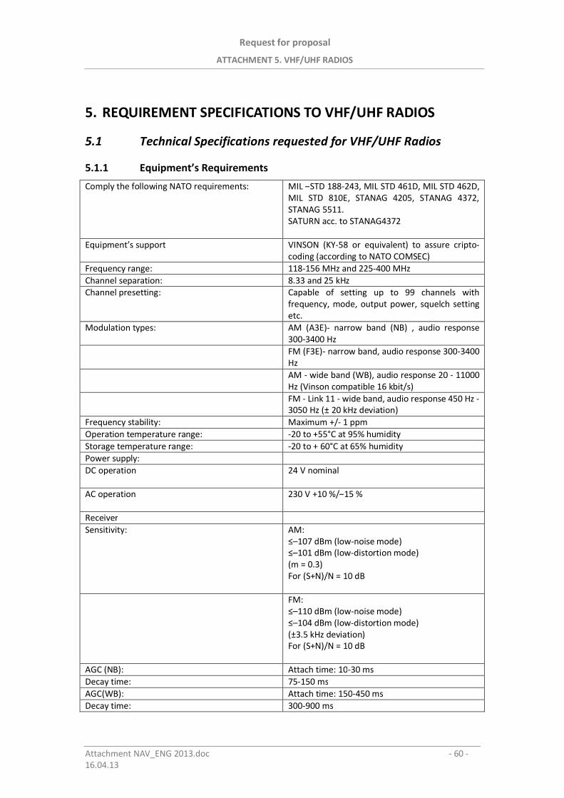
Request for proposal
ATTACHMENT 5. VHF/UHF RADIOS
Attachment NAV_ENG 2013.doc - 60 -16.04.13
5. REQUIREMENT SPECIFICATIONS TO VHF/UHF RADIOS
5.1 Technical Specifications requested for VHF/UHF Radios
5.1.1 Equipment’s Requirements
Comply the following NATO requirements: MIL –STD 188-243, MIL STD 461D, MIL STD 462D,MIL STD 810E, STANAG 4205, STANAG 4372,STANAG 5511.SATURN acc. to STANAG4372
Equipment’s support VINSON (KY-58 or equivalent) to assure cripto-coding (according to NATO COMSEC)
Frequency range: 118-156 MHz and 225-400 MHzChannel separation: 8.33 and 25 kHzChannel presetting: Capable of setting up to 99 channels with
frequency, mode, output power, squelch settingetc.
Modulation types: AM (A3E)- narrow band (NB) , audio response300-3400 HzFM (F3E)- narrow band, audio response 300-3400HzAM - wide band (WB), audio response 20 - 11000Hz (Vinson compatible 16 kbit/s)FM - Link 11 - wide band, audio response 450 Hz -3050 Hz (± 20 kHz deviation)
Frequency stability: Maximum +/- 1 ppmOperation temperature range: -20 to +55°C at 95% humidityStorage temperature range: -20 to + 60°C at 65% humidityPower supply:DC operation 24 V nominal
AC operation 230 V +10 %/–15 %
ReceiverSensitivity: AM:
–107 dBm (low-noise mode)–101 dBm (low-distortion mode)
(m = 0.3)For (S+N)/N = 10 dB
FM:–110 dBm (low-noise mode)–104 dBm (low-distortion mode)
(±3.5 kHz deviation)For (S+N)/N = 10 dB
AGC (NB): Attach time: 10-30 msDecay time: 75-150 msAGC(WB): Attach time: 150-450 msDecay time: 300-900 ms
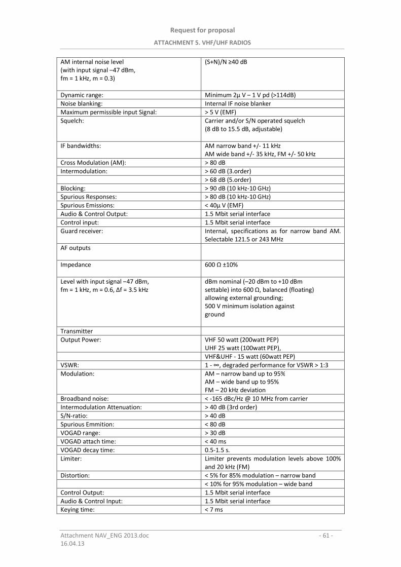
Request for proposal
ATTACHMENT 5. VHF/UHF RADIOS
Attachment NAV_ENG 2013.doc - 61 -16.04.13
AM internal noise level(with input signal –47 dBm,fm = 1 kHz, m = 0.3)
(S+N)/N 40 dB
Dynamic range: Minimum 2 V – 1 V pd (>114dB)Noise blanking: Internal IF noise blankerMaximum permissible input Signal: > 5 V (EMF)Squelch: Carrier and/or S/N operated squelch
(8 dB to 15.5 dB, adjustable)
IF bandwidths: AM narrow band +/- 11 kHzAM wide band +/- 35 kHz, FM +/- 50 kHz
Cross Modulation (AM): > 80 dBIntermodulation: > 60 dB (3.order)
> 68 dB (5.order)Blocking: > 90 dB (10 kHz-10 GHz)Spurious Responses: > 80 dB (10 kHz-10 GHz)Spurious Emissions: < 40 V (EMF)Audio & Control Output: 1.5 Mbit serial interfaceControl input: 1.5 Mbit serial interfaceGuard receiver: Internal, specifications as for narrow band AM.
Selectable 121.5 or 243 MHzAF outputs
Impedance 600 ±10%
Level with input signal –47 dBm,fm = 1 kHz, m = 0.6, f = 3.5 kHz
dBm nominal (–20 dBm to +10 dBmsettable) into 600 , balanced (floating)allowing external grounding;500 V minimum isolation againstground
TransmitterOutput Power: VHF 50 watt (200watt PEP)
UHF 25 watt (100watt PEP),VHF&UHF - 15 watt (60watt PEP)
VSWR: 1 - , degraded performance for VSWR > 1:3Modulation: AM – narrow band up to 95%
AM – wide band up to 95%FM – 20 kHz deviation
Broadband noise: < -165 dBc/Hz @ 10 MHz from carrierIntermodulation Attenuation: > 40 dB (3rd order)S/N-ratio: > 40 dBSpurious Emmition: < 80 dBVOGAD range: > 30 dBVOGAD attach time: < 40 msVOGAD decay time: 0.5-1.5 s.Limiter: Limiter prevents modulation levels above 100%
and 20 kHz (FM)Distortion: < 5% for 85% modulation – narrow band
< 10% for 95% modulation – wide bandControl Output: 1.5 Mbit serial interfaceAudio & Control Input: 1.5 Mbit serial interfaceKeying time: < 7 ms
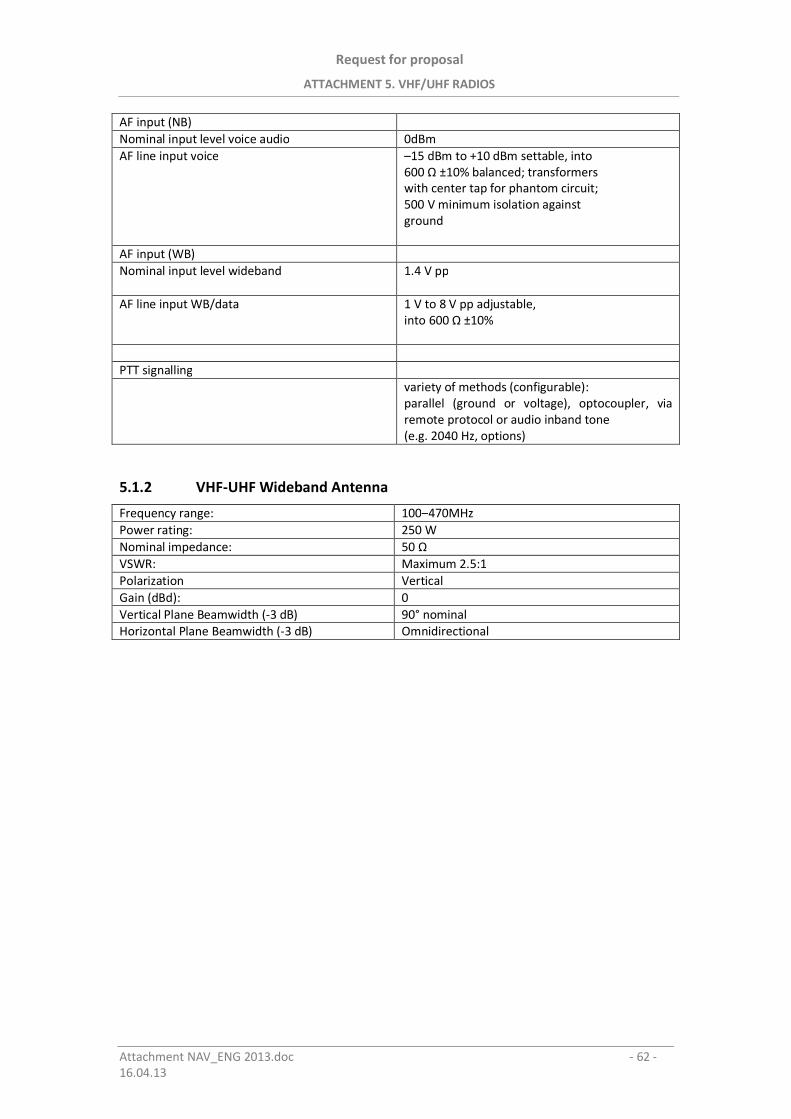
Request for proposal
ATTACHMENT 5. VHF/UHF RADIOS
Attachment NAV_ENG 2013.doc - 62 -16.04.13
AF input (NB)Nominal input level voice audio 0dBmAF line input voice –15 dBm to +10 dBm settable, into
600 ±10% balanced; transformerswith center tap for phantom circuit;500 V minimum isolation againstground
AF input (WB)Nominal input level wideband 1.4 V pp
AF line input WB/data 1 V to 8 V pp adjustable,into 600 ±10%
PTT signallingvariety of methods (configurable):parallel (ground or voltage), optocoupler, viaremote protocol or audio inband tone(e.g. 2040 Hz, options)
5.1.2 VHF-UHF Wideband Antenna
Frequency range: 100–470MHzPower rating: 250 WNominal impedance: 50 VSWR: Maximum 2.5:1Polarization VerticalGain (dBd): 0Vertical Plane Beamwidth (-3 dB) 90° nominalHorizontal Plane Beamwidth (-3 dB) Omnidirectional

Request for proposal
ATTACHMENT 6. HF RADIOS
Attachment NAV_ENG 2013.doc - 63 -16.04.13
6. PIELIKUMS / ATTACHMENT 6
Nepieciešam s specifik cijas HFradioapar tiem
Requirement Specifications to HF Radios
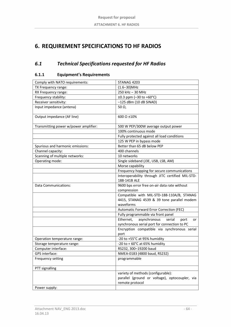
Request for proposal
ATTACHMENT 6. HF RADIOS
Attachment NAV_ENG 2013.doc - 64 -16.04.13
6. REQUIREMENT SPECIFICATIONS TO HF RADIOS
6.1 Technical Specifications requested for HF Radios
6.1.1 Equipment’s Requirements
Comply with NATO requirements: STANAG 4203TX Frequency range: (1.6–30)MHzRX Frequency range: 250 kHz – 30 MHzFrequency stability: ±0.3 ppm (–30 to +60°C)Receiver sensitivity: –125 dBm (10 dB SINAD)Input impedance (antena) 50 ,
Output impedance (AF line) 600 ±10%
Transmitting power w/power amplifier: 500 W PEP/300W average output power100% continuous modeFully protected against all load conditions125 W PEP in bypass mode
Spurious and harmonic emissions: Better than 65 dB below PEPChannel capacity: 400 channelsScanning of multiple networks: 10 networksOperating mode: Single sideband (J3E, USB, LSB, AM)
Morse capabilityFrequency hopping for secure communicationsInteroperability through JITC certified MIL-STD-188-141B ALE
Data Communications: 9600 bps error free on-air data rate withoutcompressionCompatible with MIL-STD-188-110A/B, STANAG4415, STANAG 4539 & 39 tone parallel modemwaveformsAutomatic Forward Error Correction (FEC)Fully programmable via front panelEthernet, asynchronous serial port orsynchronous serial port for connection to PCEncryption compatible via synchronous serialport
Operation temperature range: -20 to +55°C at 95% humidityStorage temperature range: -20 to + 60°C at 65% humidityComputer interface: RS232, 300–19200 baudGPS interface: NMEA-0183 (4800 baud, RS232)Frequency setting programmable
PTT signallingvariety of methods (configurable):parallel (ground or voltage), optocoupler, viaremote protocol
Power supply:
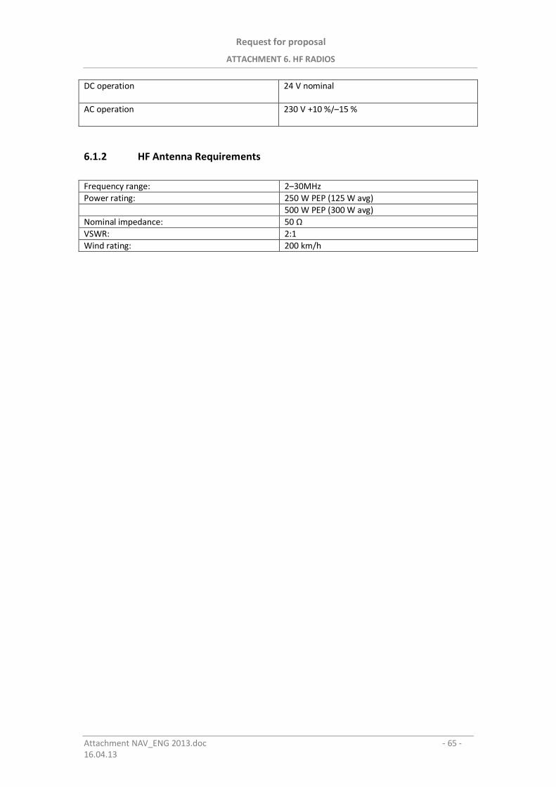
Request for proposal
ATTACHMENT 6. HF RADIOS
Attachment NAV_ENG 2013.doc - 65 -16.04.13
DC operation 24 V nominal
AC operation 230 V +10 %/–15 %
6.1.2 HF Antenna Requirements
Frequency range: 2–30MHzPower rating: 250 W PEP (125 W avg)
500 W PEP (300 W avg)Nominal impedance: 50 VSWR: 2:1Wind rating: 200 km/h
Request for proposal
ATTACHMENT 7. RECORDER SYSTEM
Attachment NAV_ENG 2013.doc - 66 -16.04.13
7. PIELIKUMS / ATTACHMENT 7
Ierakstu sist ma
Recorder System
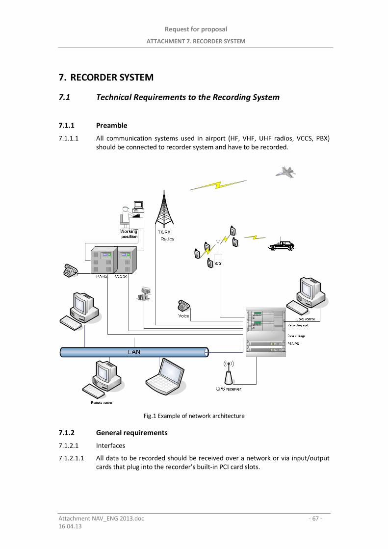
Request for proposal
ATTACHMENT 7. RECORDER SYSTEM
Attachment NAV_ENG 2013.doc - 67 -16.04.13
7. RECORDER SYSTEM
7.1 Technical Requirements to the Recording System
7.1.1 Preamble
7.1.1.1 All communication systems used in airport (HF, VHF, UHF radios, VCCS, PBX)should be connected to recorder system and have to be recorded.
Fig.1 Example of network architecture
7.1.2 General requirements
7.1.2.1 Interfaces
7.1.2.1.1 All data to be recorded should be received over a network or via input/outputcards that plug into the recorder’s built-in PCI card slots.
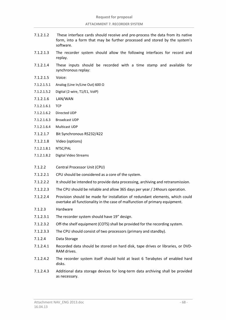
Request for proposal
ATTACHMENT 7. RECORDER SYSTEM
Attachment NAV_ENG 2013.doc - 68 -16.04.13
7.1.2.1.2 These interface cards should receive and pre-process the data from its nativeform, into a form that may be further processed and stored by the system’ssoftware.
7.1.2.1.3 The recorder system should allow the following interfaces for record andreplay.
7.1.2.1.4 These inputs should be recorded with a time stamp and available forsynchronous replay:
7.1.2.1.5 Voice:
7.1.2.1.5.1 Analog (Line In/Line Out) 600
7.1.2.1.5.2 Digital (2-wire, T1/E1, VoIP)
7.1.2.1.6 LAN/WAN
7.1.2.1.6.1 TCP
7.1.2.1.6.2 Directed UDP
7.1.2.1.6.3 Broadcast UDP
7.1.2.1.6.4 Multicast UDP
7.1.2.1.7 Bit Synchronous RS232/422
7.1.2.1.8 Video (options)
7.1.2.1.8.1 NTSC/PAL
7.1.2.1.8.2 Digital Video Streams
7.1.2.2 Central Processor Unit (CPU)
7.1.2.2.1 CPU should be considered as a core of the system.
7.1.2.2.2 It should be intended to provide data processing, archiving and retransmission.
7.1.2.2.3 The CPU should be reliable and allow 365 days per year / 24hours operation.
7.1.2.2.4 Provision should be made for installation of redundant elements, which couldovertake all functionality in the case of malfunction of primary equipment.
7.1.2.3 Hardware
7.1.2.3.1 The recorder system should have 19” design.
7.1.2.3.2 Off-the shelf equipment (COTS) shall be provided for the recording system.
7.1.2.3.3 The CPU should consist of two processors (primary and standby).
7.1.2.4 Data Storage
7.1.2.4.1 Recorded data should be stored on hard disk, tape drives or libraries, or DVD-RAM drives.
7.1.2.4.2 The recorder system itself should hold at least 6 Terabytes of enabled harddisks.
7.1.2.4.3 Additional data storage devices for long-term data archiving shall be providedas necessary.
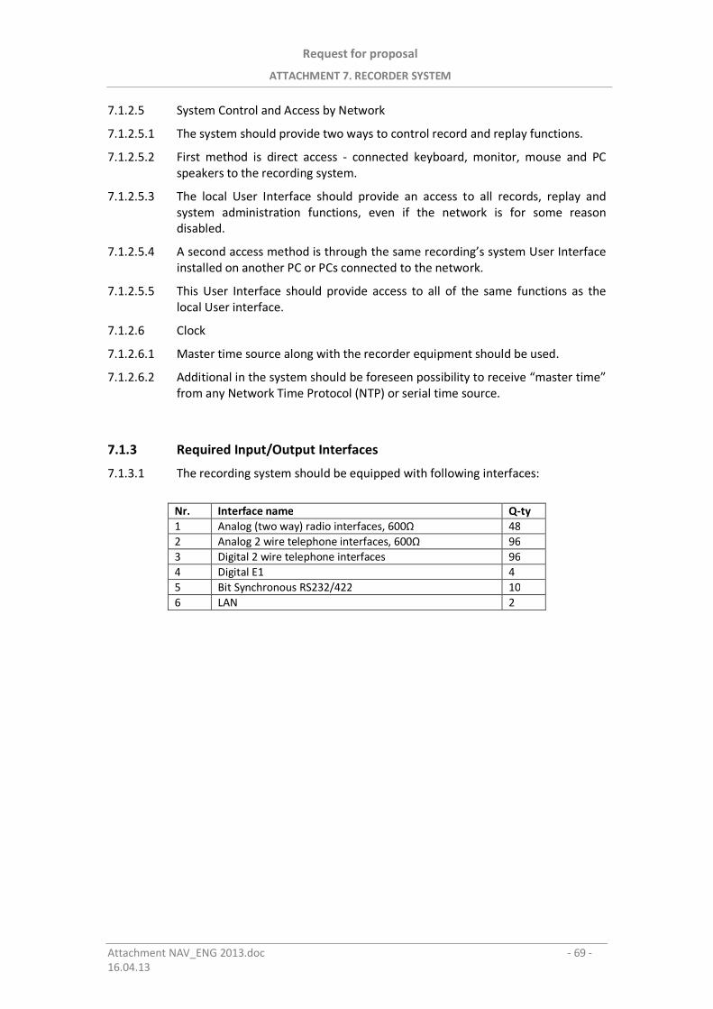
Request for proposal
ATTACHMENT 7. RECORDER SYSTEM
Attachment NAV_ENG 2013.doc - 69 -16.04.13
7.1.2.5 System Control and Access by Network
7.1.2.5.1 The system should provide two ways to control record and replay functions.
7.1.2.5.2 First method is direct access - connected keyboard, monitor, mouse and PCspeakers to the recording system.
7.1.2.5.3 The local User Interface should provide an access to all records, replay andsystem administration functions, even if the network is for some reasondisabled.
7.1.2.5.4 A second access method is through the same recording’s system User Interfaceinstalled on another PC or PCs connected to the network.
7.1.2.5.5 This User Interface should provide access to all of the same functions as thelocal User interface.
7.1.2.6 Clock
7.1.2.6.1 Master time source along with the recorder equipment should be used.
7.1.2.6.2 Additional in the system should be foreseen possibility to receive “master time”from any Network Time Protocol (NTP) or serial time source.
7.1.3 Required Input/Output Interfaces
7.1.3.1 The recording system should be equipped with following interfaces:
Nr. Interface name Q-ty1 Analog (two way) radio interfaces, 600 482 Analog 2 wire telephone interfaces, 600 963 Digital 2 wire telephone interfaces 964 Digital E1 45 Bit Synchronous RS232/422 106 LAN 2
Request for proposal
ATTACHMENT 8. D-VORTAC
Attachment NAV_ENG 2013.doc - 70 -16.04.13
8. PIELIKUMS / ATTACHMENT 8
Taktisk s aeronavig cijas sist ma D-VORTAC
Tactical Air Navigation D-VORTAC
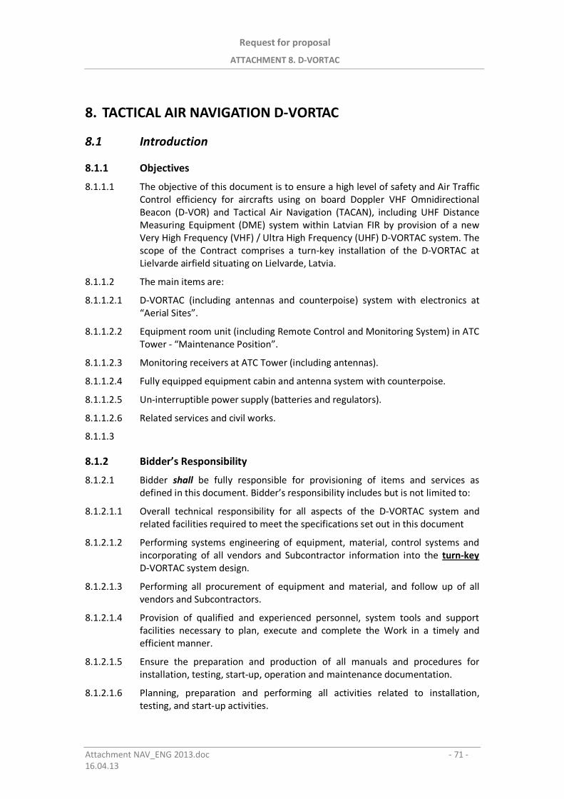
Request for proposal
ATTACHMENT 8. D-VORTAC
Attachment NAV_ENG 2013.doc - 71 -16.04.13
8. TACTICAL AIR NAVIGATION D-VORTAC
8.1 Introduction
8.1.1 Objectives
8.1.1.1 The objective of this document is to ensure a high level of safety and Air TrafficControl efficiency for aircrafts using on board Doppler VHF OmnidirectionalBeacon (D-VOR) and Tactical Air Navigation (TACAN), including UHF DistanceMeasuring Equipment (DME) system within Latvian FIR by provision of a newVery High Frequency (VHF) / Ultra High Frequency (UHF) D-VORTAC system. Thescope of the Contract comprises a turn-key installation of the D-VORTAC atLielvarde airfield situating on Lielvarde, Latvia.
8.1.1.2 The main items are:
8.1.1.2.1 D-VORTAC (including antennas and counterpoise) system with electronics at“Aerial Sites”.
8.1.1.2.2 Equipment room unit (including Remote Control and Monitoring System) in ATCTower - “Maintenance Position”.
8.1.1.2.3 Monitoring receivers at ATC Tower (including antennas).
8.1.1.2.4 Fully equipped equipment cabin and antenna system with counterpoise.
8.1.1.2.5 Un-interruptible power supply (batteries and regulators).
8.1.1.2.6 Related services and civil works.
8.1.1.3
8.1.2 Bidder’s Responsibility
8.1.2.1 Bidder shall be fully responsible for provisioning of items and services asdefined in this document. Bidder’s responsibility includes but is not limited to:
8.1.2.1.1 Overall technical responsibility for all aspects of the D-VORTAC system andrelated facilities required to meet the specifications set out in this document
8.1.2.1.2 Performing systems engineering of equipment, material, control systems andincorporating of all vendors and Subcontractor information into the turn-keyD-VORTAC system design.
8.1.2.1.3 Performing all procurement of equipment and material, and follow up of allvendors and Subcontractors.
8.1.2.1.4 Provision of qualified and experienced personnel, system tools and supportfacilities necessary to plan, execute and complete the Work in a timely andefficient manner.
8.1.2.1.5 Ensure the preparation and production of all manuals and procedures forinstallation, testing, start-up, operation and maintenance documentation.
8.1.2.1.6 Planning, preparation and performing all activities related to installation,testing, and start-up activities.
Request for proposal
ATTACHMENT 8. D-VORTAC
Attachment NAV_ENG 2013.doc - 72 -16.04.13
8.1.2.1.7 Ensure the evaluation and implementation of standardised items into theD-VORTAC to the extent practicable.
8.1.2.1.8 Present and review key documents and drawings with Purchaser as part ofBidder’s own approval system.
8.2 Scope of work and supply
8.2.1 Systems Engineering
8.2.1.1 Bidder shall conduct all systems engineering activities in accordance withestablished practices within Bidder’s organisation.
8.2.1.2 Draft drawings, reports and other documents developed as a result of systemsengineering activities performed particularly shall be provided for Purchaser’sacceptance.
8.2.2 Cabinets and Antenna System
8.2.2.1 Bidder shall deliver, install and set into operation a “VHF/UHF-band” D VORTAC-system in compliance with (latest releases):
8.2.2.1.1 All related requirements set out in ICAO Annex 10, Volume I, II, V and relatedAttachments
8.2.2.1.2 All related requirements set out in ICAO Annex 14, Volume I
8.2.2.1.3 All related requirements set out in ICAO Doc 9157 (Part 5, Part 6)
8.2.2.1.4 All related requirements set out in ICAO Doc 8071, Volume I
8.2.2.1.5 All related requirements set out in NATO STANAG 5034 Ed 3, Mil Std 291C.
8.2.2.1.6 All related requirements set out in European and International Standards andPractices.
8.2.2.1.7 Additional requirements as set out in this document.
8.2.3 Site Survey
8.2.3.1 Bidder shall conduct a site survey and prepare a site survey report.
8.2.3.2 The Site Survey Report shall at least contain:
8.2.3.2.1 Recommendations for location of D-VORTAC equipment cabin and antennasystem
8.2.3.2.2 Draft drawings for D-VORTAC equipment cabin and antenna system
8.2.3.2.3 Draft equipment installation layout drawings (including Tower equipment)
8.2.3.2.4 Installation plans (including Tower equipment)
8.2.3.2.5 Identification of all physical and electrical interfaces
Request for proposal
ATTACHMENT 8. D-VORTAC
Attachment NAV_ENG 2013.doc - 73 -16.04.13
8.2.3.2.6 Coverage diagrams
8.2.3.2.7 Updated list of Purchaser provided items
8.2.3.3
8.2.4 Flight Trials (inspection) and Assistance during Flight Trials
8.2.4.1 Flight Trials shall be considered as a part of SAT and be the responsibility ofBidder to order necessary Installation and Commissioning Flight Check fromneutral provider.
8.2.4.2 Bidder shall also make qualified personnel available for assistance ininterpreting results and if needed, further optimization of the equipment.
8.2.5 D-VORTAC Site
8.2.5.1 The D-VORTAC site will be located at the selected position near the Lielvardeairfield, central part of Latvia, near city of Lielvarde (~5 km). The height abovemean sea level is about 53 metres. The environment consists mainly of flatlandscape, fields and some forests. There is candidate for site:
8.2.5.2 D-VORTAC on the runway centre line extension, approximately 1000 metresfrom threshold RWY 36.
8.2.5.3 Approximate site co-ordinates: 56°45'32.34"N 24°50'57.58"E.
8.2.5.4 The Bidder shall mount to the cabin all necessary power and communicationlines depending of exact site position.
8.2.5.5 Earthing networks shall be installed by the Bidder.
8.2.5.6 Bidder shall be responsible for the final sitting of the equipment and specifyingall related civil works such as concrete bases for cabins and antennas, the cableducting and technical roads.
8.2.6 Site Services Requirements
8.2.6.1 Equipment Cabin
8.2.6.1.1 The D-VORTAC system shall be mounted in 19 inch racks and housed in anequipment cabin, which shall be delivered and installed by Bidder.
8.2.6.1.2 The cabin shall be equipped with a heating, ventilation and air conditioningsystem sufficient for keeping the indoor temperature within acceptabletolerances for operation of the D VORTAC and its ancillaries.
8.2.6.1.3 Estimated rate of outdoor temperature range shall be from - 35 °C to + 40 °C.
8.2.6.1.4 The cabins should in addition to equipment delivered under this deliveryinclude space for one extra full height 19 inch rack.
8.2.6.1.5 The cabin shall have sufficient space for instruments and tools needed formaintenance and repair activities.
8.2.6.1.6 The cabin construction shall be of a quality which is adapted to the climaticconditions in the region of the D VORTAC site.
Request for proposal
ATTACHMENT 8. D-VORTAC
Attachment NAV_ENG 2013.doc - 74 -16.04.13
8.2.6.1.7 It shall be designed for a life time of minimum 15 years.
8.2.6.1.8 Bidder shall provide instructions for preventive maintenance of the cabin.
8.2.6.2 Antenna System
8.2.6.2.1 The antenna system for D-VORTAC in position should have a height ofapproximately 5-7 meters for D-VOR counterpoise and co-axial mounting forTACAN/DME antennas, the real height shall be determined after site survey.
8.2.6.2.2 It is assumed that optimum height shall be decided in co-operation betweenBidder and Purchaser as result of the site survey.
8.2.6.2.3 The antenna system D-VORTAC shall be constructed so that it will meet all therequirements for maximum allowed range for D-VORTAC up to 100 NM and theconstruction shall meet requirements for frangibility (ICAO Doc 9157 AirportDesign Manual, Part 6) and all this in given wind conditions, steady and gustingup to 75 knots.
8.2.6.2.4 The antenna shall be equipped with LED obstruction lights (ICAO Type B,33 cd).
8.2.7 Mains Supply
8.2.7.1 AC Power Sub-station and standby generator system
8.2.7.1.1 Purchaser will establish output from a power sub-station and a standby dieselgenerator system for the Lielvarde Tower Building distribution box and at thedistribution box at D-VORTAC site.
8.2.7.1.2 Distribution from the distribution boxes shall be Bidder’s responsibility.
8.2.7.1.3 Bidder shall establish power cable for D-VORTAC remote equipment inside theControl Tower and to the D-VORTAC site.
8.2.7.1.4 The D-VORTAC electronic equipment at site and at tower rooms shall havepossibility to be connected to: 230 V AC and 48 V DC or 24 V DC (negative toground).
8.2.7.2 Power Consumption
8.2.7.2.1 In order to enable Purchaser to dimension the sub-station and the standbygenerator systems output Bidder shall specify the total power consumption ofthe whole installation.
8.2.7.2.2 In addition, the power consumption for major units shall be stated individually.
8.2.7.3 Un-interruptible Power Supplies
8.2.7.3.1 Uninterruptible Power Supplies (UPS’s) consisting of rectifier/charger, battery,automatic and manual bypass switches, etc. shall be dimensioned to providepower for the D-VORTAC, including antenna system, Controlling and monitoringsystem, heating, ventilation and air conditioning system and ancillariesnecessary for system operation in 90 minutes at “Aerial Site” and 30 minutesfor D-VORTAC remote equipment at Tower building.
Request for proposal
ATTACHMENT 8. D-VORTAC
Attachment NAV_ENG 2013.doc - 75 -16.04.13
8.2.7.3.2 In addition to the D-VORTAC system the UPS at “Aerial Site” shall conservativelyrated to 20% to minimum reserve capacity.
8.2.7.3.3 Bidder should state the reserve capacity of the UPS’s.
8.2.7.3.4 Further, Bidder shall state the power rating of the UPS’s under full loadconditions.
8.2.7.3.5 Bidder shall state voltage output stability given:
8.2.7.3.5.1 ±10% variation in the input voltage, and
8.2.7.3.5.2 ±20% variation in the input voltage
8.2.7.3.6 The UPS’s shall not cause any feedback harmonics to the incoming powersupply.
8.2.7.3.7 The UPS’s shall provide warnings and alarms to technical centre on:
8.2.7.3.7.1 mains failure and
8.2.7.3.7.2 “battery low”
8.2.7.3.8 The UPS’s output shall be shut down automatically under a “battery low”condition.
8.2.7.3.9 An automatic bypass facility shall be provided to allow for transfer of mainsdirectly to the incoming power supply (AC mains).
8.2.7.3.10 The UPS’s shall also incorporate a manual bypass facility.
8.2.7.3.11 Current/voltage limiters shall be provided at the output of the UPS’s forprotection of connected equipment against current/voltage surges or thelimiters shall be incorporated in the UPS’s.
8.2.7.3.12 The UPS’s shall have built-in self-protection against over-voltage, under-voltageand over-current introduced by the primary AC source.
8.2.7.3.13 The UPS’s shall have built-in self-protection against voltage surges introducedby load switching and circuit breaker operation in the distribution system
8.2.7.3.14 The battery of the UPS systems shall be of sealed type and maintenance freewith a service life of not less than 5 years.
8.2.7.3.15 The Charger of the UPS’s shall be capable of supplying full load while thebatteries are float charged or being charged from “battery low” condition.
8.2.7.3.16 Quick charge of unloaded battery within a 4-hour period while supplying 80%load should be provided.
8.2.7.3.17 Bidder shall state nominal time for quick charge under above conditions.
8.2.8 Telecommunication Services
8.2.8.1 Bidder shall establish telecommunication lines (cable) for D-VORTAC remoteequipment inside the Control Tower and to the D-VORTAC site.
Request for proposal
ATTACHMENT 8. D-VORTAC
Attachment NAV_ENG 2013.doc - 76 -16.04.13
8.2.9 Maintenance Adjustments and Test Points
8.2.9.1 Maintenance adjustments in form of easily accessible adjustment control shallbe provided for adjustment of equipment operating parameters.
8.2.9.2 Easily accessible test points without using extension cards etc shall be providedfor adjustments and measurement observation of operating parameters.
8.2.9.3 Also, test points for check of major wave forms and voltages, used for testingthe equipment shall be provided.
8.2.9.4 All test points shall be provided with a “TP” number or similar sign.
8.2.9.5 The system should be designed to provide for connections for such testequipment as may be required for installation, maintenance, calibration andrepair.
8.2.9.6 System operation shall not be degraded as a result of connection of testequipment to any test point.
8.2.9.7 Short circuit of any of test points shall not cause component failure.
8.2.10 Maintenance Actions during Operation
8.2.10.1 With due observance of the safety regulations, it shall be possible to carry outmaintenance work on one part of the equipment while the rest is operating.
8.2.10.2 It shall also be possible to switch off all power in one part of the equipment formaintenance work.
8.2.11 Exact Site Co-ordinates and Heights
8.2.11.1 After antenna installation, but before the Commissioning Flight Trials Biddershall, using Subcontractors, organise measurements of all site geographical co-ordinates and heights (including also all monitor and control antennas)according to Latvian Civil Aviation Administration (LCAA) requirements.
Request for proposal
ATTACHMENT 8. D-VORTAC
Attachment NAV_ENG 2013.doc - 77 -16.04.13
8.3 D-VORTAC Technical specifications
8.3.1 Specification and Standards
8.3.1.1 The D-VORTAC shall comply with, or exceed where so indicated, thespecifications applicable to D-VORTAC at standards listed in Paragraph 2.2.1.
8.3.1.2 All materials, workmanship and tests shall be in accordance with the bestaccepted standards for this class of equipment, to fulfil requirements of ICAOAnnex 10, Volume I for the ILS CAT II.
8.3.2 Alternatives
8.3.2.1 Bidder is free to offer any design of equipment, which in his opinion, will beequal to or better than the requirements of this specification.
8.3.2.2 Bidder shall state the performance he is prepared to guarantee.
8.3.3 General Requirements
8.3.3.1 The equipment shall be constructed as appropriate of modular plug-in sub-assemblies,each of which shall be easily and quickly replaced by one person.
8.3.3.2 Plug-in modular construction is essential to insure rapid return to service aftermaintenance.
8.3.3.3 The service life of the D-VORTAC equipment shall be approximately 12 years.The degree to which current technology is used should therefore be a factor inthe evaluation process.
8.3.3.4 The D-VORTAC equipment shall be designed to operate under the strongatmospheric and topographical conditions.
8.3.3.5 The stability of adjustments, the circuit techniques and the components usedshall be such that the equipment requires routine inspection only at longintervals.
8.3.3.6 Bidder shall state the calculated MTBF and MTTR of the proposed D-VORTACand MTBCF - Mean Time Between Critical Failure during peace time and wartime, where appropriate.
8.3.3.7 Quotations Proposal shall be supported by adequate technical documentation(hard&soft copy) comprising equipment lists and illustrations, technicalbrochures, layout drawings, dimensional sketches, etc. to facilitate full andcomplete understanding of the equipment under offer and a comparativeevaluation of the equipment against all specified parameters.
Request for proposal
ATTACHMENT 8. D-VORTAC
Attachment NAV_ENG 2013.doc - 78 -16.04.13
8.3.4 Technical Requirements for D-VORTAC equipment
8.3.4.1 The dual electronic cabinets (preferably 19’’ inch) shall include fully solid statecomponents.
8.3.4.2 The transmitters of the D-VORTAC shall be easily adjustable to any frequency atD-VOR “VHF band”: 111,075 MHz – 117,975 MHz
8.3.4.3 The D-VOR shall have preset channels with step 50 kHz (frequency channels).
8.3.4.4 The frequency tolerance applicable to D-VOR shall be at least ±0.002 per centand to TACAN shall be ±0.001 per cent.
8.3.4.5 The D-VORTAC output power radiated shall be such as permit satisfactoryoperation of a typical aircraft installation at the required flight levels – 60 000 ftand distances 100 NM and up to elevation angle of 40 degrees.
8.3.4.6 The normal transmitter module for D-VOR shall be 100W, programmable, withlow harmonic level and for TACAN Peak Output Power - 1-5 kW (DME 1 kW),programmable
8.3.4.7 The D-VOR radio frequency carrier shall be amplitude modulated (AM) by twosignals:
8.3.4.7.1 a subcarrier of 9960 Hz of constant amplitude, frequency modulated at 30 Hzand having a deviation ratio of 16 plus or minus 1 (i.e. 15 to 17), where thephase of the 30 Hz component varies with azimuth and is termed “the variablephase”.
8.3.4.7.2 a 30 Hz AM component of constant phase with relation to azimuth and constantamplitude is radiated omnidirectionally and is termed the “reference phase”.
8.3.4.7.3 The depth of modulation of the radio frequency carrier due to the subcarrier of9960 Hz shall be within the limits of 28 to 32 percent.
8.3.4.7.4 The depth of modulation of the radio frequency carrier due to the 30 Hz or9960 Hz signals, as observed at any angle of elevation up to 5 degrees, shall bewithin the limits of 28 to 32 percent.
8.3.4.7.5 The variable and reference phase modulation frequencies shall be 30 Hz withinplus or minus 1 percent,
8.3.4.7.6 The subcarrier modulation mid frequency shall be 9960 Hz within plus or minus1 percent,
8.3.4.7.7 The percentage of AM of te 9960 Hz subcarrier shall not exceed 40 per-centwhen measured at point at least 300 metres from the D-VOR,
8.3.4.7.8 The sideband level of the harmonics of the 9960 Hz component in the radiatedsignal shall not exceed the following levels referred to the level of the 9960 Hzsideband:
Subcarrier Level9960 Hz 0 dB reference2nd harmonic -30 dB3rd harmonic -50 dB4th harmonic -60 dB
Request for proposal
ATTACHMENT 8. D-VORTAC
Attachment NAV_ENG 2013.doc - 79 -16.04.13
8.3.4.8 The TACAN radio frequency (RF) Pulse Spectrum, Spurious Outputs andharmonics shall be relevant to International standards.
8.3.4.9 The TACAN Pulse Rise Time, Pulse Fall Time and Pulse Duration shall be relevantto International standards.
8.3.4.10 The TACAN Ident rate shall be relevant to International standards.
8.3.4.11 The TACAN transponder Pulse Pair Spacing shall be:
8.3.4.11.1 for X channel – 12 s ± 0.1 s;
8.3.4.11.2 for Y channel – 30 s ± 0.1 s.
8.3.4.12 The TACAN Auxiliary Reference Pulse Group shall be:
8.3.4.12.1 for X channel – 6 pairs of pulses at 24 s ± 0.1 s;
8.3.4.12.2 for Y channel – 13 single pulses at 30 s ± 0.1 s.
8.3.4.13 The TACAN Pulse Repetition Rate shall be not less than 2700 ± 90 pulse pairsper second and up to 5400 pulse pairs per second.
8.3.4.14 The TACAN Pulse Coding Precedence shall be:
8.3.4.14.1 main reference group;
8.3.4.14.2 auxiliary reference group;
8.3.4.14.3 identity signal;
8.3.4.14.4 distance replies,
8.3.4.14.5 random pulse pairs.
8.3.4.15 The TACAN Distance Reply Signal shall be for X Mode – 50 s, for Y Mode – 56s, it should be capable of being to set from nominal value up to plus or minus
15 s, to permit aircraft interrogators to indicate zero distance at a specificpoint remote from the transponder site.
8.3.4.16 The TACAN Distance Accuracy shall be ± 15 metres (± 50 feet)
8.3.4.17 The TACAN Reply Delay Time Stability shall be:
Input Signal Delay Signal0 to -10 dBm ± 0.5 s-10 to -70 dBm ± 0.1 s-70 to -91 dBm ± 0.8 s
8.3.4.18 The D-VOR system voice and identification shall be relevant to ICAO Annex 10.
8.3.4.19 The TACAN (DME) identification shall be „associated” with D-VOR and relevantto International standards
8.3.4.20 Equalising pair should be transmitted 100 s ± 10 s after each Identity pulse.
8.3.4.21 The dual TACAN shall be capable to operate in TACAN, demand and DME onlymodes.
8.3.4.22 The TACAN transponder receiver sensitivity with minimum power densitiesminus 103 dBW/m2 shall cause the transponder to reply with an efficiency of atleast 70 per cent.
Request for proposal
ATTACHMENT 8. D-VORTAC
Attachment NAV_ENG 2013.doc - 80 -16.04.13
8.3.4.23 Dummy Load in transmitters’ cabinets shall be in order to enable theadjustment of the transmitters.
8.3.4.24 For the maintenance of the D-VORTAC according to the requirements in Doc8017 Manual of Testing Radio Navigation Aids shall be supplied with necessarymeasurement hardware: (multimeters’, field intensity meter, frequency meter(carrier), oscilloscope, RF thermocouple ammeter).
8.3.5 Operator position of D-VORTAC equipment
8.3.5.1 The Operator position shall be capable to control via the interrogator theoperation of TACAN transponder and via receiver the D-VOR bearing and radialsignals.
8.3.5.2 The Operator position should be capable to change the operation of TACAN in –silent, demand and DME only modes.
8.3.6 Control and Monitoring System (CMS)
8.3.6.1 A local maintenance position (Local CMS or Local Maintenance Monitor LMM)shall be installed at “Aerial Site”
8.3.6.2 Two remote maintenance positions (Remote CMS or Remote MaintenanceMonitor RMM – PC based and remote control and status indicator) withEMCON switch shall be installed at tower Technical Room.
8.3.6.3 The TACAN Control and Monitoring System (CMS) shall be on the site dual (twoidentical control modules and monitors) and capable to perform on the local orremote PC display via communication cable with communication system:
8.3.6.3.1 the following functions:
8.3.6.3.1.1 Overall system status
8.3.6.3.1.2 Show operating parameters
8.3.6.3.1.3 Line Replaceable Units (LRU) status
8.3.6.3.1.4 Alarm limits
8.3.6.3.1.5 Diagnostic
8.3.6.3.1.6 Test Information
8.3.6.3.1.7 Amplifier Status
8.3.6.3.1.8 Transmitter control Status, etc.
8.3.6.3.2 the monitor shall cause following action to take place:
8.3.6.3.2.1 A suitable indication shall be given at control point;
8.3.6.3.2.2 The operating transponder shall be switched off, and
8.3.6.3.2.3 Standby transponder shall be automatically placed in operation;
8.3.6.3.2.4 Means shall be provided so that any conditions and malfunctioning which aremonitored can persist for a certain period before the monitor takes action. This periodshall be as low as possible, but shall not exceed 10 seconds;
Request for proposal
ATTACHMENT 8. D-VORTAC
Attachment NAV_ENG 2013.doc - 81 -16.04.13
8.3.6.3.2.5 The transponder shall not be triggered more than 120 times per second for eithermonitoring or automatic frequency control purposes, or both.
8.3.6.4 The Control and Monitoring System (and BITE system) shall be capable toperform the following checking functions on the TACAN in hereinafter casesand transfer signalisation of alarm from the TACAN position to the towerbuilding technical room to in the event of module failure, system transfer orshutdown:
8.3.6.4.1 The transponder delay differs from the assigned value by 0.5 microsecond ormore;
8.3.6.4.2 The spacing between the first and second pulse of the transponder pulse pairdiffers from the nominal value;
8.3.6.4.3 A fall of 3 dB or more in transponder transmitted power output;
8.3.6.4.4 A fall of 6 dB or more in the minimum transponder receiver sensitivity(provided that this is not due to the action of the receiver automatic gainreduction circuits),
8.3.6.4.5 The spacing between the first and second pulse of the transponder reply pulsepair differs from the normal value;
8.3.6.4.6 Variation of the transponder receiver and transmitter frequencies beyond thecontrol range of the reference circuits (if the operating frequencies are notdirectly crystal controlled)
8.3.6.4.7 Absence of mains;
8.3.6.4.8 Operation on standby
8.3.6.4.9 Automatic or manual operation
8.3.6.4.10 Faulty rectifier
8.3.6.5 A feedback control loop shall be used at the TACAN to provide control of thePulse shape and Spectrum and to keep them within permissible limits, over alloperating conditions and providing self correction wherever possible.
8.3.6.6 The D-VOR Remote Maintenance and Monitoring (RMM/R-CMS) systemstations on the D-VORTAC site and at the Tower building technical room shallbe connected via fibre optic line, using communication system.
8.3.6.7 The RMM (R-CMS) system shall provide:
8.3.6.7.1 Fault diagnostic to LRU level,
8.3.6.7.2 Remote display of operating parameters,
8.3.6.7.3 Monitoring of test functions,
8.3.6.7.4 Event logging/trend analysis and
8.3.6.7.5 A field monitor self-test facility.
8.3.6.8 The RMM (R-CMS) system shall display on screens:
8.3.6.8.1 Operating parameters,
8.3.6.8.2 Overall system status,
8.3.6.8.3 LRU status,
Request for proposal
ATTACHMENT 8. D-VORTAC
Attachment NAV_ENG 2013.doc - 82 -16.04.13
8.3.6.8.4 Alarm limits,
8.3.6.8.5 Diagnostics and test,
8.3.6.8.6 Amplifier status,
8.3.6.8.7 Transmitter control status
8.3.6.8.8 Transmitter power level
8.3.6.8.9 9960 Hz modulation depth
8.3.6.8.10 30 Hz modulation depth
8.3.6.8.11 Ident.
8.3.6.9 The status information in the technical room in the tower building shall beupdated from D-VORTAC site at regular intervals and presented on eachconnection:
8.3.6.9.1 as a list panel during the inquiry;
8.3.6.9.2 in the “Historical File” associated with each set D-VORTAC;
8.3.6.9.3 in a synthetic file system ”Last States Received”.
8.3.6.9.4 LRU status screen indicates which module is faulty.
8.3.6.10 If this update fails the Communication Link Shut-Down information shall beactivated.
8.3.6.11 The D VORTAC CMS shall have the function to:
8.3.6.11.1 to switch ON or OFF the D-VORTAC operation,
8.3.6.11.2 to switch over transmitters 1 to 2 or inversely;
8.3.6.11.3 reset of the equipment (software),
8.3.6.11.4 to change the mains.
8.3.6.12 On the technical room of Tower building shall be possibility through the tele-control system, based on PC (with operational system WINDOWS 7, XP, VISTAor LINUX) to remotely collect the information regarding the operation of thisequipment for each (but is not limited to):
8.3.6.12.1 Configuration:
8.3.6.12.1.1 code signal;
8.3.6.12.1.2 Automatic or manual operation;
8.3.6.12.2 Parameters:
8.3.6.12.2.1 Active transmitter;
8.3.6.12.2.2 Direct power;
8.3.6.12.2.3 Power supply voltage
8.3.6.12.3 External signaling (worded by user, like as example):
8.3.6.12.3.1 faulty mains
8.3.6.12.3.2 faulty rectifier
8.3.6.12.3.3 faulty diesel engine generator
Request for proposal
ATTACHMENT 8. D-VORTAC
Attachment NAV_ENG 2013.doc - 83 -16.04.13
8.3.6.12.3.4 fire extinguisher system alarm
8.3.6.13 Telecontrol system should be connected with site additionally through the GSMnetwork.
8.3.7 D-VORTAC Control interrogator and Antenna
8.3.7.1 The TACAN control interrogator module (based on airborne type) and itsantenna shall be proposed for TACAN functioning remote control purposes inthe absence of aircrafts at the Technical room of the Tower.
8.3.7.2 For interrogator antenna - shall be proposed necessary antenna with cabling.
8.3.7.3 The PC screen or annunciator shall be supplied by the associated interrogatorand transmit for Operator signals:
8.3.7.3.1 Bearing
8.3.7.3.2 From, To,
8.3.7.3.3 Distance in NM,
8.3.8 Antenna System
8.3.8.1 The D-VOR antenna system (aerial) shall be with 1 + 48 sideband aerials (AlfordLoop) and shall be designed as a double sideband system having a minimum ofdistortion on the 9960 Hz sub-carrier.
8.3.8.2 The D-VOR shall have two monitor antennas.
8.3.8.3 The TACAN E-Scan antenna system (electronically modulated) shall be coaxiallycollocated with D-VOR antenna system (at the same vertical axis).
8.3.8.4 The emission from the D-VOR antenna shall be horizontally polarised and thevertically polarised component of the radiation shall be as small as possible.
8.3.8.5 The accuracy of the bearing information conveyed by the horizontally polarizedradiation from the D-VOR at a distance of approximately four wavelength for allelevation angles between 0 and 40 degrees, measured from the centre of theD-VOR antenna system, shall be within plus or minus 2 degrees.
8.3.8.6 The counterpoise shall be a hot dip galvanised metal support and framestructure with galvanised steel wire lattice of which the material andconstruction is robust and strong enough to withstand wind speeds of up to 200km/h.
8.3.8.7 The height of counterpoise shall be decided after Bidders site visit.
8.3.8.8 The antenna coaxial connectors shall be preferably of the “N” type, withimpedance 50 ohms.
Request for proposal
ATTACHMENT 8. D-VORTAC
Attachment NAV_ENG 2013.doc - 84 -16.04.13
8.3.8.9 The antenna shall withstand a wind velocity of at least 150 km/h.
8.3.8.10 The antenna shall be capable to operate within the temperature range -30°C to+60°C and tolerate relative humidity up to 95%.
8.3.8.11 The supplied DVOR station main principle shall be based on double sidebandmethod.
8.3.8.12 To achieve best DVOR performance the antenna system shall implement atleast 48 sideband antennas.
8.3.8.13 The DVOR antennas, which installed close together must be activated and fedconsecutively to reduce parasitic radiation coupled in from neighbouringantennas. The parasitic excitation of the sideband antennas caused by coupledradiation should be reduced to -20 dB.
8.3.8.14 The spurious 60 Hz modulation caused by the rotation of the radiation shall bereduced to a negligible value by feeding antennas which are not directlyadjacent.
8.3.8.15 A failure of one, two or three sideband antennas shall not lead the failure ofantenna system, but shall cause merely a minor fault in the 30 Hz FM.
8.3.8.16 The DVOR shall be equipped by two next field antenna system and far fieldantenna system. The far field antenna cost should be separated presentedseparately as option.
8.3.8.17 The DVOR supports and counterpoise shall be manufactured from hot-dip-galvanized steel. The Bidder shall guarantee it anticorrosive for at least 15years.
8.3.8.18 The DVOR antenna shall be supplied with stairs equipped by hand-rail. Thestairs width shall be not less than 1 meter. The stairs shall include at least twoplatforms at 4 and 7 meters (for 8 meters height counterpoise) height forpersonal rest during get up to counterpoise. The platforms square shall not beless than 1.5 m2. The stairs shall be developed from grid to avoid ice and snowsticking. The grid side shall be not more than 1 sm. The counterpoise openingshall inside sideband antennas ring and be secured from intruders by keyedlock. The opening shall be fasten to counterpoise by stitches. The weight of theopening shall be not more than 15 kilograms.
8.3.8.19 The counterpoise shall be developed from grid to avoid ice and snow sticking.The 1 meter grid ring from both sides of the side band antennas shall bedeveloped from 1 sm. side grid. The 1 meter width radius from sidebandantennas ring to central antenna, next field antennas and to the DME antennashall be developed from the same grid. The edge of grid to the DME antennashould be equipped with safe rail. The DME antenna position at the edge ofcounterpoise should be secured by 1 meter height fibroblastic fence.
8.3.8.20 The DME antenna placed on the counterpoise shall be equipped by obstructionlights and shall be foldable. The all counterpoise surface where DME antennaplaced after it sinking shall be developed from 1 sm. side grid with width 1meter.