navfac p-1010 october 1985 - wbdg · pdf files1 4- ceramic insulators for tower base, e....
TRANSCRIPT

NAVFAC P-1010October 1985
DM-Distribution updated 5/6/85 (CRW)DISTRIBUTION: (1 copy each unless otherwise specified)SWDL39B42L249A2AA3A5A6B2AB5C7C37A2CC37A2BC37F7E3AFA6
COMCBFIGHTER SQ (VF l54 only)ADMSUPPUNAVY STAFF (ONR only)CHIEF OF NAVAL OPERATIONSCHNAVPERSCOMMANDANT MC (code LFF)(JCS, NSA, DLA, DNA only)USCG only)DEFATTOFF (Brazil & Chile only)SUFWPNCENDET[Silver Spring only)R&D CTR(Annapolis only)NAVWPNSTA ANNEX (Fallbrook only)LAB ONR(Wash.DC only)NAS LANT(Bermuda, Brunswick,Cecil Field, Jacksonville, Key West,Norfolk, Virginia Beach only)NAVSTA LANT(Brooklyn, Guantanamo,Keflavik, Mayport, Panama Canal,Philadelphia, Roosevelt Rds only)SUB BASE LANTPHIBASE LANTFAC LANT(Antigua, Argentia,Brawdy, only)CINCLANT CBUNAF PAC (Atsugi, El Centro,Midway, Misawa only)NAS PAC(Alameda, Fallon,Lemoore, Miramar,Moffett Field, Oak Harbor only)NAVSTA PAC (Seattle only)SUBASE PAC (Bangor only)PHIBASE PACFLEACT PAC (Kadena, Sasebo only)FAC PAC (Big Sur, Coos Head,Ferndale, and Pacific Beach only)SUPPFAC PACACTIVITY EUR (London only)SUPPORT ACTIVITY EURNAVAL STATIONSUPPORT OFFICENAVAIRSTANAVAL OCEAN. COMMSECGRPHQSECURITY STATIONSECGRUACT (Edzell,Hanza, Homestead, Sabana Seca,Sonoma, Winter Harbor only)COMNAVDISTNAVAL OBSERVATORYNAVAL ACADEMY
FA7
FAl0FA18FA23
FA32
FB7
FB10FBl3FB21FB34FB36
FF1FF6FF38
COMSTA (Balboa, Harold Holt,Nea Makri, Thurso, Stockton,Yokosuka,San Miguel only)COMM UNIT (East Machias only)CA MASTER STAS (Norfolk only)COMNAVMEDCOMAIR SYSTEMS COMMSYSCOMM, ELEX(Code O4M2, 20 copies)SYSCOMM, SUPSYSCOM, SEA
FKA6Al
FKA6A3AFKA6A3BFKA6A9FKA6Al2FKA6Al5FKA9FKM8FKM9FKM13FKM15FKNl
FKN2FKN3FKN5FKN7FKN10FKNllFKPlBFKPlEFKPlJFKP1MFKP7FKQ3FKRlAFKRlBFKR3AFKR3HFKR4BFKR5FKR7EFRlFR3FR4FRl5FTlFT2FT6FTl8FTl9FT22
FT28FT31FT37FT55FT74AFT78V2V3V5V8V12V14Vl5V17V22V23V25
AIR DEVELOPMENT CENTERNAVAL WEAPONS CENTERSHIP RESEARCH & DEV.CEN.COASTAL SYSTEMS CENTERSURFACE WEAPONS CENTEROCEAN SYSTEMS CENTERUNDERWATER SYSTEMS CENTERSUBSUPPBASESUPPLY ANNEXMSC (Oakland only)SHIPS PARTS & CONTROL CENASO (Philadelphia only)LANTDIV (100 copies)CHESDIV (50 copies)NORTHDIV (200 copies)PACDIV (200 copies)SOUTHDIV (200 copies)WESTDIV (200 copies)CBCOICC (6 copies each)PWC (5 copies each)ENERGY ENVIRON SUPP ACTSUPPORT ACT, NAV FACCELWPNSTAUNDERSEA WARFARE ENGR STANAVAL ORDNANCE STATIONWEAPONS SUPPLY CENTERNAVAL SHIPYARDSELECTRONIC STMS ENGR CENAIR STATIONS R&DAIR REWORK FACILITYAIR ENGINEERING CENTERAIR PROPULSION CENTERMISSILE RANGE FACILITYAVIONICS CENTERAVIATION LOGISTICS CENTERCHIEF OF NAVAL RESERVESAIR STATIONSAIR FACILITIESSUPPACTCHIEF NAVAL ENGR. TRAININGCHIEF NAVAL AIR TRAININGAIR STATIONSCONSTR. BATTALION UNIT CBCADMINCOM (San Diego only)FLECOMATRACEN (VirginiaBeach only)EDUCATION & TRAINING CENTRAINING CENTERSCHOOL CBC OFFICERSSCHOOL SUPPLY CORPS(MIT ONLY)ED & TRNG PGM DEV CENMARCORPS BARRACKS SUPPORTMC AIR BASE COMMANDMC AIR BASEMC RECRUIT DEPOTMC DEVELOP & EDUCATION CENMC HEADQUARTERS BATTALIONMC DISTRICTMC CAMPGLENVIEW, Ill. only, 2 cy.)MC LOGISTICS BASEMC AIR GROUND COMBAT CEN
STOCKED: Naval Publications and Forms Center5801 Tabor AvenuePhiladelphia, Pa. 19120

EDITED BY:
DR. MICHAEL YACHNIS, CHIEF ENGINEER
NAVAL FACILITIES ENGINEERING COMMAND
i

Contributors
1. Michael Yachnis, Chief Engineer and Consultant of Special Structures (Code04B), Special Advisor for Engineering, (Code O9T).
2. Joseph Tyrrell, Consultant) Earthquake Engineering and Weapons Effects(Code 04BA)
3. Michael Jones, Consultant, Geotechnical and Paving (04Bl)
4. Richard Thomas, Consultant, POL Facilities (04B3)
5. John Cecilio, Consultant, Material Engineering (04B4)
6. Donald Potter, Specialist, Waterfront Structures (04B5)
7. Robert Johnston, Specialist, Hyperbaric Support System (04Ba)
8. Terry Hayes, Specialist, Hyperbaric, Electrical-Electronic Systems (04Bb)
9. Edward Mifflin, Specialist, Antenna Systems (04Bc)
10. Lajos Wernigg, Specialist, Environmental Engineering (04Bd)
11. Arthur Wu, Specialist, Geotechnical and Paving (04Be)
12. Percy Malone, Specialist, Weight Handling Equipment (O4Bf)
13. Columbus Key, Specialist, Roofing Systems (04Bg)
The authors wish to thank Commodore F. G. Kelley, Vice Commander, NAVFACand Captain J. R. Ives, Deputy Commander for Facilities Acquisition, NAVFAC,for their superb support and encouragement during the preparation of thiswork. They also wish to acknowledge the excellent typing and assembly by Ms.Patricia Ferguson, Chief Engineer's secretary and the splendid guidance andhelp received from Mr. Brad Clark, NAVFAC Documentation Division.
ii
CONTENTS
STRUCTURAL
Sl - Failure of Precast Concrete Lintels, M. YachnisS2 - Overload of Roof Trusses, M. YachnisS3 - Anchorage Failure of Wall Panels, M. YachnisS4 - Distress in Floor, Naval Academy, M. YachnisS5 - Construction & Test of Pressure Vessels, J. V. TyrrellS6 - Seismic Codes, J. V. TyrrellS7 - Seismic Soft Story, J. V. TyrrellS8 - Safe Design for Blast Loading, J. V. TyrrellS9 - Structural Adequacy, J. V. TyrrellSl0 - Precast Concrete Arch/ Structural Details, J. V. TyrrellSll - Bolt Failures, J. Cecilio & E. MifflinS12 - Sheetpiling, J. CecilioSl3 - Excessive Welding in Guyed Tower, E. MifflinS14 - Ceramic Insulators for Tower Base, E. MifflinSl5 - Glass Reinforced Plastic Guy Insulators-Towers, E. MifflinS16 - Spherical Bearing for Guyed Towers, E. MifflinS17 - Drydock Analysis, A. WuS18 - Concrete Repair, P. Malone
METALLURGICAL
ML1 - Weathering Steel, J. CecilioML2 - Use of Special Materials-Antennas, E. MifflinML3 - Galling of Sluice Gates, J. Cecilio
FATIGUE
Fl - Connections of Struts for Grading Rings-Antennas, E. MifflinF2 - Eyebolt Failures - Antennas, E. Mifflin
CORROSION
CR1 - Piping Corrosion, J. CecilioCR2 - Corrosion of Aluminum in Wood, J. CecilioCR3 - Corrosion of Galvanized Guy Cables, E. MifflinCR4 - Steel Conduit, T. HayesCR5 - Improper Ventilation in Sump Areas, T. HayesCR6 - Galvanized Piping System for Hyperbaric Chambers, R. JohnstonCR7 - Mariner Steel Fender Piling, J. Cecilio
WFLDING & NON-DESTRUCTIVE TESTING
Wl - Distortions in Welded Structures, J. CecilioW2 - Acceptance & Inspection Criteria, J. V. Tyrrell
iii
PAGE
123
121316161717181920202121212232
33333 4
353 5
363 63737373838
4041
CIVIL
C1 - Industrial Waste Treatment, L. Wernigg & J. Yacoub
PAVING
P1 - Concrete Overlays on Concrete Pavements, M. JonesP2 - Granular Interlayers in Pavement Overlays, M. JonesP3 - Steel Fiber Reinforced Concrete-Airfield Pavements, M. JonesP4 - Asphalt Slurry Seals on Airfield Pavements, M. Jones
SOILS & FOUNDATIONS
G1 - Subsidence of Soil at the Naval Research Laboratory, M. YachnisG2 - Failure of Concrete Caissons at Naval Medical Ctr., M. YachisG3 - Failure of Steel Fuel Task, Sigonella, Italy, M. YachnisG4 - A Foundation Failure in Compressible Soils, M. JonesG5 - Expansive Soils, M. JonesG6 - Sheet Piling/Bulkheads Replacement, A. Wu
42
66686868
707171737575
G7 - Lateral Earth Pressure & Structural Adequacy of Drydock Wall,A. Wu 83G8 - Pile Driving Problems, A. WuG9 - Landfill Stabilization. Naval Academy, A. WuG10 - Foundation on Compacted Fill, A. WuG11 - Failure of Timber Pile Foundation, NRL, M. Yachnis
POL FACILITIES/ENERGY
POL 1 - POL Storage Tanks-Spark Generating Equipment, R. Thomas 97POL 2 - Thermal Expansion of Fuel, R. Thomas 97POL 3 - Tires for Refueling Vehicles/FOD Hazard, R. Thomas 98POL 4 - Failure of Filter/Separators, R. Thomas 98POL 5 - Pressure Relief Valve (PRV), R. Thomas 99POL 6 - Spring Loaded Check Valve, R. Thomas 99POL 7 - Latex Lining System for Concrete Fuel Tanks, R. Thomas 99POL 8 - Explosive Clearance fur Fuel Facilities, R. Thomas 100POL 9 - Flow Control at Direct Fueling Stations, R. Thomas 100POL 10 - Pressure Control at Direct Fueling Stations, R. Thomas 100POL 11 - Pantograph Stops, R. Thomas 101POL 12 - Static Electricity at Direct Fueling Stations, R. Thomas 101POL 13 - Corroded Fuel Tank Bottom, R. Thomas 102POL 14 - MIL Specification Fueling Hose, R. Thomas 102POL 15 - Petroleum Fuels/Energy, R. Thomas 102
MECHANICAL & HYPERBARICS
M1 - Raceway Tubing for Hyperbaric Complex, T. Hayes 104M2- Submersible Pump for Fire (Hyperbaric Chamber), T. Hayes 104M3- Air for Manned Chambers, T. Hayes 104M4 - Oxygen Enriched Testing of Materials, T. Hayes 105M5 - Drain Plugs for Recompression Chambers, T. Hayes 105M6 - Drywall Nails for Hyperbaric Facilities, T. Hayes 105M7- Bypasses for Gas Piping Systems (Hyperbaric), R. Johnston 105M8 - Oxygen Dump System, R. Johnston 106M9 - Materials for Oxygen Systems, T. Hayes 106
iv
M10 - Volume of Ventilation Air-Hyperbarics, T. HayesM11 - Selection of Filters-Breathing Air System, R. JohnstonM12 - Freeze-up of Dome Pressure Regulators, R. JohnstonM13 - Manned Chambers - Pressurization Problems (Doors), R. JohnstonM14 - Air System Drying After Hydro Test, R. JohnstonM15 - Location of Intake for Air Supply, R. JohnstonM16 - Pressurization of Chamber Fire Extinguishers, R. JohnstonM17 - Hyperbaric Chamber BIB System, R. JohnstonM18 - Hyperbaric Recompression Chamber, R. JohnstonM19 - Hyperbaric Pressure Relief/Safety Valve, R. Johnston
CRANES
CN1 - Floating Cranes; Free-fall Restraint, P. MaloneCN2 - Non-destructive Testing of Crane Hooks, P. Malone/D. PotterCN3 - Safety of Booms for Mobile Cranes, P. MaloneCN4 - Safety of Slings & Fittings, P. MaloneCN5 - Capacity of Barge Mounted Mobile Cranes, P. MaloneCN6 - Float Requirements for Portal Cranes, P. MaloneCN7 - Rotate Structures on Portal and Floating Cranes, P. Malone
PHYSICAL SECURITY
PS1 - Failure of Barbed Ribbon Tape, J. CecilioPS2 - Vehicle Barriers, J. TyrrellPS3 - Failure of Barbed Tape Obstacle, J. Cecilio
ARCHITECTURAL
A1 - Leaking Ammunition Storage Magazines, C. KeyA2 - Slippage of Roofing Membrane, C. KeyA3 - Alligatoring of Aluminum Pigmented Roofing Coating, C. KeyA4 - Wind Blown Aggregate Surfacing on Roofing, C. KeyA5 - Poor Adhesion & Blistering of Roofing, C. KeyA6 - Blistering of Built-up Roofing, C. KeyA7 - Temperature for Asphaltic Roofing, C. KeyA8 - Vapor Retarders for Roofing, C. KeyA9 - Lack of Information on Roofing Materials for Constn., C. KeyA10 - Interior Roof Drain Problems, C. KeyA11 - Roofing Flashing Failures, C. Key
CONTRACTS & CONSTRUCTION
CC1 - Failure of Wall, M. YachnisCC2 - Contractual Dispute - Light Pole, M. YachnisCC3 - Substitution for Design Requirements, J. V. TyrrellCC4 - Acceptance of Off-the-Shelf Structures, J. V. TyrrellCC5 - Erection of Cantilever Hangar, J. V. TyrrellCC6 - Tower Base Plate, E. Mifflin
106107107107108108108109109109
110110111111111112113
114114115
116116117117117118118119119119120
122123123124124125
CC7CC8 -
Specification Definition for Fill, A. WuSewer Pipes, A. Wu
CC9 - Failure of the Outlooker-Handrail System, Henderson Hall,M. Yachnis
MA1- Shipyard Items Requiring Maintenance, T. HayesMA2- Maintenance for Roofs, C. Key
PAINTS & COATINGS- -
PS1 - Flour Paint, P. Malone
vi
125125
126
130130
131
STRUCTURAL & METALLURGICAL
CASE S1 - Failure of Precast Concrete Lintels, M. Yachnis
Problem: Failure of precast reinforced concrete lintels in a building whichresulted in a great loss of money and construction time.
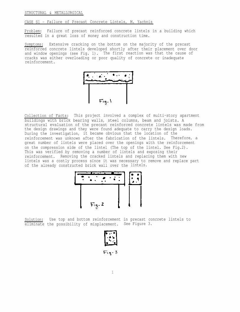
Symptoms: Extensive cracking on the bottom on the majority of the precastreinforced concrete lintels developed shortly after their placement over doorand window openings (see Fig. 1). The first reaction was that the cause ofcracks was either overloading or poor quality of concrete or inadequatereinforcement.
Collection of Facts: This project involved a complex of multi-story apartmentbuildings with brick bearing walls, steel columns, beam and joists. Astructural evaluation of the precast reinforced concrete lintels was made fromthe design drawings and they were found adequate to carry the design loads.During the investigation, it became obvious that the location of thereinforcement was unknown after the fabrication of the lintels. Therefore, agreat number of lintels were placed over the openings with the reinforcementon the compression side of the lintel (The top of the lintel. See Fig.2).This was verified by removing a number of lintels and exposing theirreinforcement. Removing the cracked lintels and replacing them with newlintels was a costly process since it was necessary to remove and replace partof the already constructed brick wall over the lintels.
Solution: Use top and bottom reinforcement in precast concrete lintels toeliminate the possibility of misplacement. See Figure 3.
1
CASE S2 - Overload of Roof Trusses, M. Yachnis
Problem: Overloading of roof trusses-storage building, Patuxent River.
Symptoms: A visual inspection showed excessive deflection of the roof trusseswith indications of cracks and torsion at the bottom elements of the trusses.Measurements taken indicated deflections in excess of 2 inches.
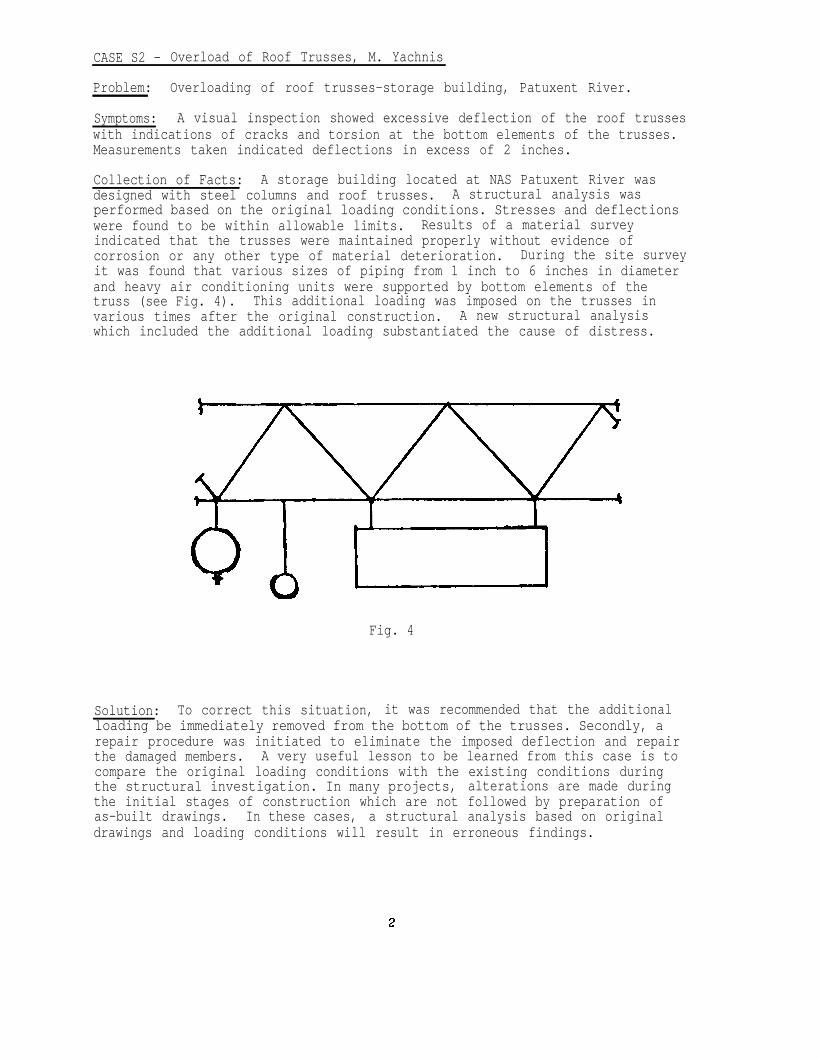
Collection of Facts: A storage building located at NAS Patuxent River wasdesigned with steel columns and roof trusses. A structural analysis wasperformed based on the original loading conditions. Stresses and deflectionswere found to be within allowable limits. Results of a material surveyindicated that the trusses were maintained properly without evidence ofcorrosion or any other type of material deterioration. During the site surveyit was found that various sizes of piping from 1 inch to 6 inches in diameterand heavy air conditioning units were supported by bottom elements of thetruss (see Fig. 4). This additional loading was imposed on the trusses invarious times after the original construction. A new structural analysiswhich included the additional loading substantiated the cause of distress.
Fig. 4
Solution: To correct this situation, it was recommended that the additionalloading be immediately removed from the bottom of the trusses. Secondly, arepair procedure was initiated to eliminate the imposed deflection and repairthe damaged members. A very useful lesson to be learned from this case is tocompare the original loading conditions with the existing conditions duringthe structural investigation. In many projects, alterations are made duringthe initial stages of construction which are not followed by preparation ofas-built drawings. In these cases, a structural analysis based on originaldrawings and loading conditions will result in erroneous findings.
CASE S3 - Anchorage Failure of Wall Panels, M. Yachnis
Problem: Movement of precast concrete panels attached to the structuralmembers.
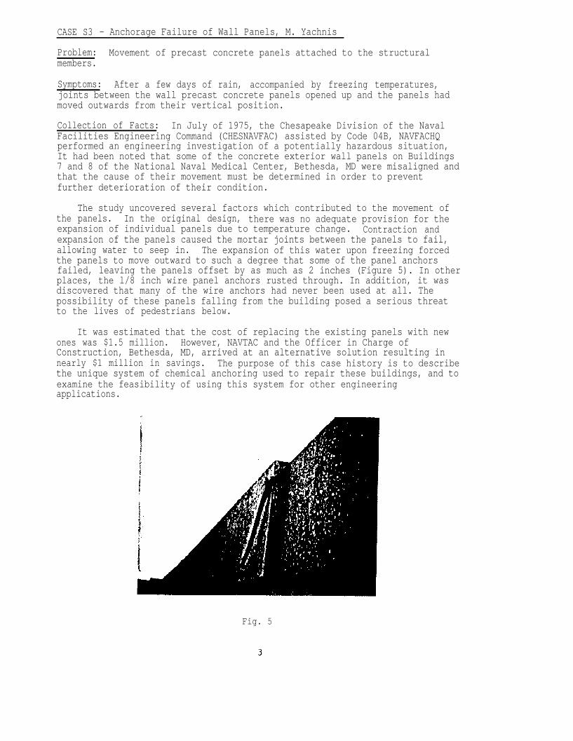
Symptoms: After a few days of rain, accompanied by freezing temperatures,joints between the wall precast concrete panels opened up and the panels hadmoved outwards from their vertical position.
Collection of Facts: In July of 1975, the Chesapeake Division of the NavalFacilities Engineering Command (CHESNAVFAC) assisted by Code 04B, NAVFACHQperformed an engineering investigation of a potentially hazardous situation,It had been noted that some of the concrete exterior wall panels on Buildings7 and 8 of the National Naval Medical Center, Bethesda, MD were misaligned andthat the cause of their movement must be determined in order to preventfurther deterioration of their condition.
The study uncovered several factors which contributed to the movement ofthe panels. In the original design, there was no adequate provision for theexpansion of individual panels due to temperature change. Contraction andexpansion of the panels caused the mortar joints between the panels to fail,allowing water to seep in. The expansion of this water upon freezing forcedthe panels to move outward to such a degree that some of the panel anchorsfailed, leaving the panels offset by as much as 2 inches (Figure 5). In otherplaces, the l/8 inch wire panel anchors rusted through. In addition, it wasdiscovered that many of the wire anchors had never been used at all. Thepossibility of these panels falling from the building posed a serious threatto the lives of pedestrians below.
It was estimated that the cost of replacing the existing panels with newones was $1.5 million. However, NAVTAC and the Officer in Charge ofConstruction, Bethesda, MD, arrived at an alternative solution resulting innearly $1 million in savings. The purpose of this case history is to describethe unique system of chemical anchoring used to repair these buildings, and toexamine the feasibility of using this system for other engineeringapplications.
Fig. 5
5
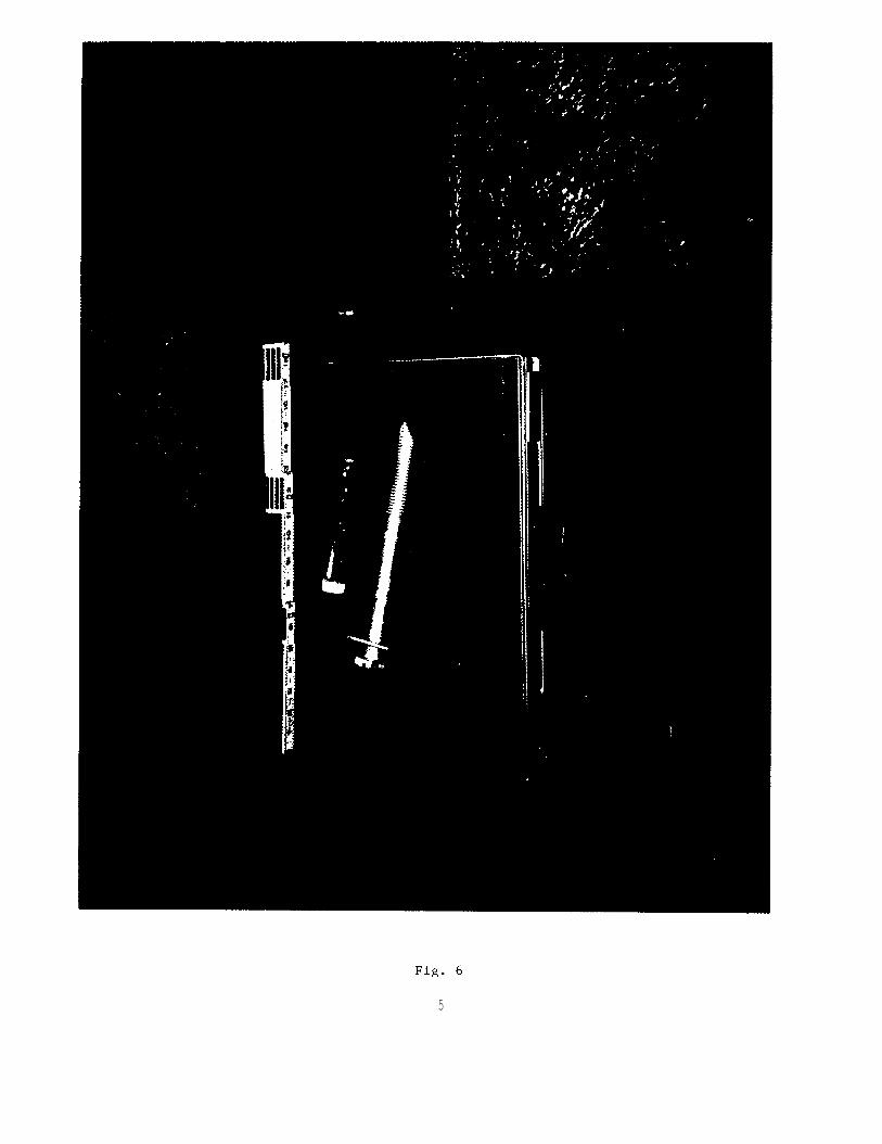
Fig. 7
Fig. 9
8
1. Advantages of the System
The chemical epoxy anchoring system was chosen because of the followingdistinct advantages it has over typical anchoring systems:
a. When an expansion anchor is used, the torquing required to fasten theanchor introduces stress into the panel which may result in damage orfailure. The chemical anchor does not expand and therefore does notproduce this excessive stress in the concrete.
b. Placement of the chemical anchor is unaffected by wet conditions. Itmay even be installed under water and the steel stud will not corrodein the bore hole.
C. The epoxy bonds effectively in a diamond bit drilled hole and pulloutvalues of up to 55 kips (with dynamic invariance) may be obtained.
The above reasons combined with the fact that the installation of thesystem is fast and simple (the epoxy components are guaranteed to be correctlyproportioned and will set in 30 minutes at 20°C (68°F)) made it desirableover all other systems considered.
2. Other Applications
The advantages of this unique system also make it useful for otherapplications. The resin cartridges were originally developed for use in mineroof bolting. A mining company in Pennsylvania has found that by using thechemical anchoring system, the time required for overcast construction in itsmine advancing operations was reduced. The resin-grouted anchor bolt is usedin combination with a spin-in bolt to assure horizontal control duringblasting and to eliminate the need for rebolting the mine roof afterblasting. Because of the strong bond developed between the bolt and the rock,the roof bolts are insensitive to blasting damage which may ordinarily resultin the loss of bolt tension. Further, the chemical anchoring system does nothave the problems of anchor creep and rock breakage around the bearing platethat mechanically anchored systems have.
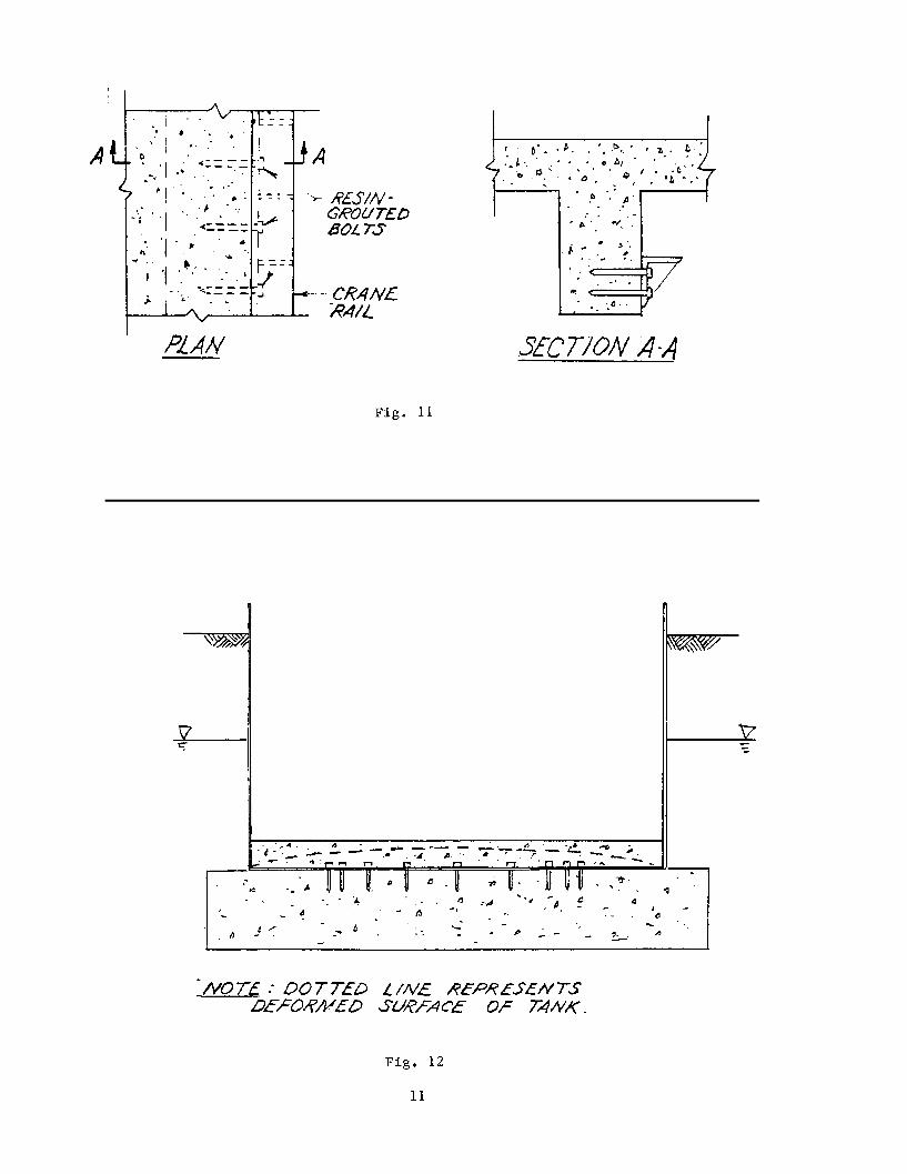
The resin-grouted bolts may also be useful in anchoring the rails ofOverhead Electric Traveling (OET) Cranes. Typically, the crane rails aresupported by steel or concrete columns. However, an angle with stiffenerplates could be anchored to a spandrel beam to achieve the same result at alower cost (Figure 11). In situations where excessive crane loads wouldrequire impractical bolting schemes, the anchors may be used in combinationwith columns to substantially reduce the cost of the columns. This railingsystem would be very reliable because of the anchor bolt's extremely highpullout values and because it is unaffected by dynamic loading.
Underground steel fuel tanks subject to uplift due to hydrostatic pressurecan be anchored by using the chemical anchoring system. Holes may be drilledthrough the bottom of the tank to grout the bolts into the concrete foundationbelow (Fig. 12).
10
On a smaller scale, the epoxy grouted bolts could be used to anchorretrofit signs, flag poles, or lighting systems. Its high pullout valuesmight be used in suspending equipment from ceilings to save floor space. Itsquality of being shock and vibration proof would be advantageous in securingheavy machinery.
3. Conclusions
During the 1978 Annual Meeting of the Minnesota Section, AmericanInstitute of Mining Engineers, J. Holmes of the University of Minnesotadetermined that resin-grouted bolts are more effective than mechanicallyanchored rock bolts. However, he cited several safety precautions whichshould be taken to insure their dependability. Among his comments, he statedthat holes must be drilled to the proper depth to assure full bonding, andthat care should be taken to store and install the bolts within the range oftemperatures specified by the manufacturer.
Despite these potential problems, the chemical anchoring system possessesmany characteristics which are often needed in various engineeringapplications. Its effectiveness in remedial work was evidenced in theeconomical repair work performed on Buildings 7 and 8 at the National NavalMedical Center, but perhaps the system's broadest and most valuableapplications are in the area of retrofitting existing structures. It seemsclear that given more examination, experimentation, and exposure to theengineering community, the chemical anchoring system will provide sound andeconomical solutions to many future engineering challenges.
CASE S4 - Distress in Floor, M. Yachnis
Problem: Distress on the floor of Bancroft Hall, at the U.S. Naval. Academy,Annapolis, Maryland.
Symptoms: Excessive vibration of floor due to live loading.
Collection of Facts: A/E performed a structural engineering investigation andconcluded that the floor was adequate to carry only 3 P.S.F. live load. Byobserving the midshipmen marching in formation on the floor, it was obviousthat the floor was adequate to carry more than 3 P.S.F. live load. A test wasperformed in accordance with ACI code requirements and the floor was found tobe adequate for 180 P.S.F.
Solution: When the results of computations are disputed, perform a test withadequate instrumentation.
12
CASE S5 - Construction & Test of Pressure Vessels, J. V. Tyrrell
Problem: Safety of Pressure Test of Vessels with Defects.
Background: The Naval Air Propulsion Center, W. Trenton, N.J. has a number oftest cells for turbo prop and jet engines. Three of these for jet engineshave the ability to simulate operating conditions at altitude. While thesefacilities are not the largest of their kind, they are still (in 1985) some ofthe most sophisticated. Intake air is fed into the system severing all cellsby a bank of very large blowers in a parallel configuration.
The air passes through heaters or refrigeration units into one of the testchambers containing the engine to be tested. Each test chamber is served byan exhaust gas cooler. The engine drives the exhaust and augmentation airthru the system but it is also drawn out of the gas coolers by a bank ofexhaust blowers similar to but smaller than the intake blowers. The system isnot only subject to high and low temperatures but operating pressures may varyfrom 60 psig to minus 15 psig.
Problem: S5a - Welding repair/stress relief.
Symptoms: Excessive deformation, jammed doors.
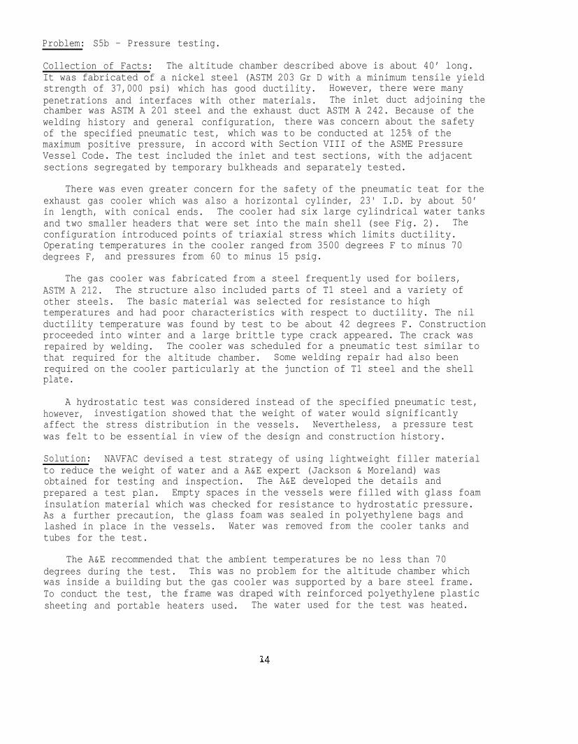
Collection of Facts: The newest of the altitude test chambers is a cylinderwith its longitudinal axis horizontal and with truncated cones at each end astransitions to the intake and exhaust (see Fig. 1). The chamber may besubjected to temperatures ranging from 400 degrees F to minus 70 degrees F,and pressures from 60 to minus 15 psig. Jet engines are moved in and outthrough a large clam shell type door. The basic cylinder and the door areboth reinforced by series of circumferential stiffeners.
Radiographic inspection of the welds joining the stiffeners to the shellrevealed that over 90% were defective. Consequently a large amount of thewelding was repaired. Because of the temperature and pressure conditions andthe triaxial stress at the junction of the shell and stiffeners, stress reliefof repaired welds was recommended. The contractor then attempted toaccomplish this by heating the whole chamber. The chamber was supported ontwo concrete piers. As the temperature rose, the chamber sagged under its ownweight.
Solution: In the case in question, it was feasible to repair or replace thedamaged chamber. Fortunately, the distortion was not significant for the airflow. The door was modified to permit proper closure, and supports for theinternal working platform were adjusted.
Stress relief (particularly in the field) must be carefully considered andplanned or it may do more harm than good.
13
Problem: S5b - Pressure testing.
Collection of Facts: The altitude chamber described above is about 40’ long.It was fabricated of a nickel steel (ASTM 203 Gr D with a minimum tensile yieldstrength of 37,000 psi) which has good ductility. However, there were manypenetrations and interfaces with other materials. The inlet duct adjoining thechamber was ASTM A 201 steel and the exhaust duct ASTM A 242. Because of thewelding history and general configuration, there was concern about the safetyof the specified pneumatic test, which was to be conducted at 125% of themaximum positive pressure, in accord with Section VIII of the ASME PressureVessel Code. The test included the inlet and test sections, with the adjacentsections segregated by temporary bulkheads and separately tested.
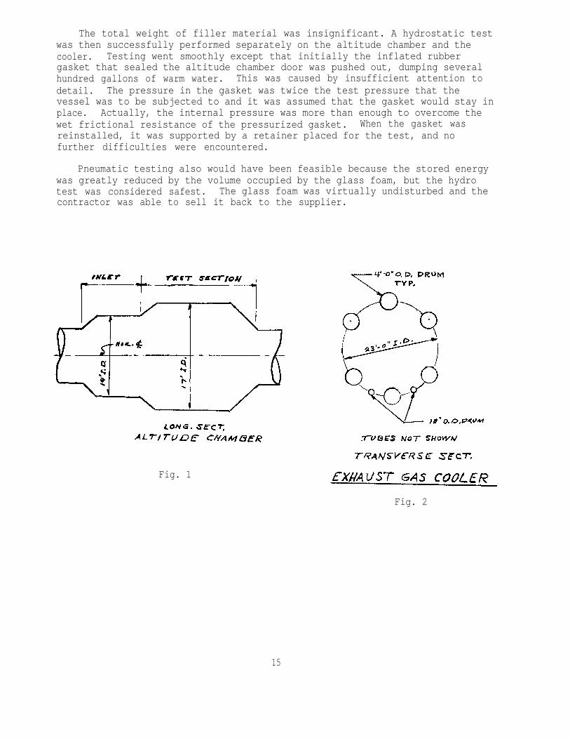
There was even greater concern for the safety of the pneumatic teat for theexhaust gas cooler which was also a horizontal cylinder, 23' I.D. by about 50’in length, with conical ends. The cooler had six large cylindrical water tanksand two smaller headers that were set into the main shell (see Fig. 2). Theconfiguration introduced points of triaxial stress which limits ductility.Operating temperatures in the cooler ranged from 3500 degrees F to minus 70degrees F, and pressures from 60 to minus 15 psig.
The gas cooler was fabricated from a steel frequently used for boilers,ASTM A 212. The structure also included parts of T1 steel and a variety ofother steels. The basic material was selected for resistance to hightemperatures and had poor characteristics with respect to ductility. The nilductility temperature was found by test to be about 42 degrees F. Constructionproceeded into winter and a large brittle type crack appeared. The crack wasrepaired by welding. The cooler was scheduled for a pneumatic test similar tothat required for the altitude chamber. Some welding repair had also beenrequired on the cooler particularly at the junction of T1 steel and the shellplate.
A hydrostatic test was considered instead of the specified pneumatic test,however, investigation showed that the weight of water would significantlyaffect the stress distribution in the vessels. Nevertheless, a pressure testwas felt to be essential in view of the design and construction history.
Solution: NAVFAC devised a test strategy of using lightweight filler materialto reduce the weight of water and a A&E expert (Jackson & Moreland) wasobtained for testing and inspection. The A&E developed the details andprepared a test plan. Empty spaces in the vessels were filled with glass foaminsulation material which was checked for resistance to hydrostatic pressure.As a further precaution, the glass foam was sealed in polyethylene bags andlashed in place in the vessels. Water was removed from the cooler tanks andtubes for the test.
The A&E recommended that the ambient temperatures be no less than 70degrees during the test. This was no problem for the altitude chamber whichwas inside a building but the gas cooler was supported by a bare steel frame.To conduct the test, the frame was draped with reinforced polyethylene plasticsheeting and portable heaters used. The water used for the test was heated.
The total weight of filler material was insignificant. A hydrostatic testwas then successfully performed separately on the altitude chamber and thecooler. Testing went smoothly except that initially the inflated rubbergasket that sealed the altitude chamber door was pushed out, dumping severalhundred gallons of warm water. This was caused by insufficient attention todetail. The pressure in the gasket was twice the test pressure that thevessel was to be subjected to and it was assumed that the gasket would stay inplace. Actually, the internal pressure was more than enough to overcome thewet frictional resistance of the pressurized gasket. When the gasket wasreinstalled, it was supported by a retainer placed for the test, and nofurther difficulties were encountered.
Pneumatic testing also would have been feasible because the stored energywas greatly reduced by the volume occupied by the glass foam, but the hydrotest was considered safest. The glass foam was virtually undisturbed and thecontractor was able to sell it back to the supplier.
Fig. 1
Fig. 2
15
CASE S6 - Seismic Codes, J. V. Tyrrell
Problem: Unacceptable Seismic Design
Symptoms: Distress in structures; requests for criteria waivers
Collection of Facts: One of the most common mistakes, made in connection withearthquake design, is the assumption that a structure which can resist codelateral forces is OK, even though it does not meet the detailed requirementsof the code. These requirements are put in the code on the basis ofexperience. Many are necessary to insure ductility. The philosophy ofseismic codes has been to use lateral forces which are considerably less thanthe maximum forces that would be associated with the largest earthquakemotions expected to be seen at the site. It is expected that structures sodesigned will be undamaged by a moderate earthquake and will not collapseunder the maximum earthquake.
Solution: The detailed provisions of the code are necessary to provide theductility to meet performance expectations. Do not attempt to use portions ofa design code selectively. Good details and adequate connections are asimportant to earthquake performance as the forces applied as design loads.
CASE S7 - Seismic Soft Story J. V. Tyrrell
Problem: Earthquake damage.
Symptoms: Damage to columns; discontinuous shear walls; failures.
Collection of Facts: In the late 1950's and 60's, a seismic design conceptwas introduced which utilized shear walls except for one story, usually thefirst floor, where a moment resisting frame was used. The idea was to absorbenergy by inelastic deformations at this story. In practice, a number ofserious failures have resulted, such as the Olive View hospital which wasdamaged in the 1971 San Fernando quake. In other cases, the same sort ofproblem has sometimes occurred unintentionally where discontinuities in shearwalls have been used to accommodate architectural purposes.
Solution: It is evident that it is highly desirable to carry shear walls downto the foundation level.
16
CASE S8 - Safe Design for Blast Loading, J. V. Tyrrell
Problem: Structures just beyond explosives safety distances
Symptom: Unexpected damage.
Collection of Facts: Usually no consideration of blast loading is given tostructures located outside the explosive safety arc for inhabited buildings.Although there is seldom significant damage outside of this arc, it ispossible that the blast environment could be important for certainstructures. Failure to consider this loading could result in damage rangingfrom broken glass to serious structural effects.
Solution: For important structures which are to be sited just outside theexplosive safety arc for inhabited buildings, it is worthwhile to consider theblast environment that the structure may see.
CASE S9 - Structural Adequacy, J. V. Tyrrell
Problem: Structures not designed by engineers.
Symptom: Structural failures/unsatisfactory performance.
Collection of Facts: A large dead-end structure was designed for anelectrical distribution line terminating at a transformer substation. Becausethe drawings were prepared by a well known manufacturer of electricalequipment, it was assumed that the structural design was adequate. It turnedout that the structure was inadequate for the loading imposed.
Solution: Whenever a structure is a part of a manufacturer's package, requirethat the design drawings bear the seal of a professional engineer.
17
CASE S1O - Precast Concrete Arch/ Structural Details, J. V. Tyrrell
Problem: Inattention to structural details
Symptoms: Structural failures
Collection of Facts: A large precast concrete arch with a steel tie rod wasdesigned to be supported by concrete piers. The arch was cast in two segmentsto be connected at the crown during erection. The piers were designed ascantilever members with spread footings proportioned to take lateral thrust onthe piers during erection, before the tie was connected. Although the soilbearing capacity was adequate, no consideration was given to the effect that asmall settlement might have on the position of the arch seats.
The tie was designed as a tension member and a rod of minimum size wasselected. The rod was strong enough to resist the maximum load but again noconsideration was given the effect of elastic stretch on the piers. Thecontractor devised an erection scheme that called for several arches to beerected before the first tie rod was placed. This work was performed withoutshoring, and the process was observed by the A&E when about three arches werein place without the tie. The ROICC mentioned that the piers appeared to havemoved outward slightly and a check showed a movement a little over one inch.The A&E said that this was not a problem but should be watched.
The next day, a failure during erection caused injury to the constructioncrew and extensive structural damage. The primary cause was determined to bethe failure to immediately connect the tie rods or alternatively provideadequate shoring. The structural calculations were then reviewed and it wasfound that even with erection completed and the tie in place, the stabilitywas only marginal.
Solution: There are no complete solutions to these problems. Designers musttry to think about the function of the entire system and not just crank outdesign for the major factors such as shear and moment. The designer shouldtry to foresee potential problems in erection. When erection is complicated,unusual, or involves major structures, the contractor should submit anerection plan which is structurally checked. As you can see, not payingattention to details continues to be a principal cause of structural failures.
18
CASE S11 - Bolt Failures, E. L. Mifflin & J. J. Cecilio
Problem: S11a - Failure of ASTM A-325 bolts. ASTM A-325 bolts hot dippedgalvanized can produce cracks or cracks can be produced at a later time whenthey are exposed to a marine environment, if their hardness exceeds Rockwell"C-32". Stress corrosion or other brittle type failure is likely.
Symptoms: Cracks can develop in the annular space around the bolts and in theroots of the threads; consequently, heads of bolts may fall off.
Collection of Facts: Hot dipped galvanizing can release atomic hydrogen (H)which permeates the ASTM A-325 bolts. This can result in hydrogen inducedcracking. This has been experienced in several situations including stitchbolts for a 1500 foot guyed tower where the heads fell creating a hazard topersons on the ground.
Solution: Do not dip galvanized ASTM A-325 bolts if their hardness exceedsRockwell "C-32”. If galvanizing is necessary, hardness should not exceed C-32,For stitch bolts, A-307 should be adequate and less costly than A-325.
CASE S11 - Continued
Problem: S11b - Failure of ASTM A-490 bolts. ASTM A-490 bolts hot dippedgalvanized can produce cracks and fail.
Symptoms: Cracks can develop in the annular space around the bolts and in theroots of the threads.
Collection of Facts: The problem of galvanized A-490 bolts is similar to thatexperienced with A-325 bolts. Hot dipped galvanizing can release atomichydrogen (H) which permeates the ASTM A-490 bolts. This can result inhydrogen induced cracking.
Solution: ASTM A-490 bolts should never be galvanized.
Problem: S11c - Failure of non-galvanized ASTM A325 and ASTM A490 bolts. Ifnon-galvanized ASTM A325 and ASTM A490 bolts are attached to galvanizedplates, the non-galvanized bolts may develop cracks and fail, if theirhardness exceeds Rockwell "RC-32".
Symptoms: Cracks can develop in the annular space of the bolts.
Collection of Facts: Bolts that are nut galvanized, if put into contact withmetal which is galvanized, may develop cracks. ASTM A325 or ASTM A490 boltswith a hardness of RC-32 or greater are subject to this problem, and potentialfailure.
Solution. Do not place ASTM A325 or ASTM A490 bolts, which have a hardnessequal or in excess of Rockwell C-32, in contact with a galvanized surface.
19
CASE 512 - Sheet Piling, J.J. Cecilio
Problem: Inadequate dimensional control of welded and extruded "Y's".
Symptom: Cracks/tears/failures.
Collection of Facts: ASTM A328 "Steel Sheetpiling" and A690 "High StrengthLow-Alloy Steel Piles and Sheetpiling" for use in marine environments dependon specification A-6 for dimensions control and markings. The markings in12.3 is quite adequate; however, the dimensional control is inadequate relatedto the interlock dimension variation. This is especially true of riveted,welded and extruded "Y's".
Solution: The specification for the specific application should specify notonly interlock strength, but also specific interlock dimensions with limitedvariations. It is noted here that the dimensions vary up and down the lengthof the sheetpiles and "Y's", especially the extruded ones. The weakest pointon these piles from available data appears to be at approximately 75% of thelength from the lead of hook-end as they pass through the dies or rolls.Hence dimensional variation is important.
Additional data is available from the NAVFAC library in NRL Memorandum Report3869 "Trident Cofferdam Analysis" by C. D. Beachem dated January 2, 1979.
CASE S13 - Excessive Welding for a Guyed Tower, E. L. Mifflin
Problem: Unnecessary cost of welds for vertical member splices.
Symptom: In one case, approximately 70% of the welded fabrication of a towerwas in the flange plates used to splice the vertical members.
Collection of Facts: Usually the vertical members and legs of a guyed towerare solid round bars. The legs are compression members that must be veryaccurately finished on the ends for true alignment in the field. The onlytime the member is in tension is in the erection of the mast or when it is ina cantilevered top. Many of the splice designs use a donut shaped platecontinuously welded to the solid round bar to connect one leg to another. Themain compressive force is transmitted through bearing of solid round ends.These donut shaped plates tend to be very thick.
In one specific design, the plates were three (3) to four (4) inches thick.The designer called for full penetration continuous welds. This was excessiveand amounted to seventy (70) percent of the shop welding of the tower. Thisexcessive amount of welding, coupled with the complex welding procedures forthe material used in design (90,000 psi yield heat treated alloy steel),resulted in a very expensive structure. Continuous welding was required for afatigue resistant design, but full penetration welds were not needed.
Solution: This is a special case where it would have paid to economize on aconnection by careful design that would have considered or even specifiederection procedures and actual stress requirements. Of course, it isnecessary to consider the nature of the connection, the type of material, andthe service conditions in designing the weld. In the case cited, the designwas adequate but involved unnecessary expense.
20
CASE S14 - Ceramic Insulators for Tower Base, E. L. Mifflin
Problem: High cost of ceramic insulators for guys in tall guyed towers.
Symptom: Excessive bids.
Collection of Facts: Studies of the cost of "fail safe" guy insulators for600 foot low frequency radiators showed 40 percent of material cost went for"failsafe" insulators. These insulators represented a significant part ofthe total cost. The cost was reduced by switching to non-fail safe insulatorsfor the top radial systems where additional safety was not needed. The lasttwo Omega towers designed by the government showed that using a 200 foothigher (1400 feet) grounded tower was less expensive because base and guyinsulators could be eliminated.
Solution: Design VLF/LF antenna systems around available insulators whenpossible and consider alternatives to base insulated towers.
CASE S15 - Glass-Reinforced Plastic Guy Insulators, E. Mifflin
Problem: Use of lightweight glass reinforced plastic guy insulators astension members. (In high voltage antennas).
Symptom: Failures in insulation due to tracking, electrical internalpuncture, burning and explosive type disintegration.
Collection of Facts: In most cases of use of this type of insulators in highvoltage application, one or more of the above symptoms occurred rendering theinsulator useless. Only one type of insulator has passed a radio frequencyhigh voltage test and has a five (5) year in-service record. This successfulinsulator is a fiberglass core reinforced cycloaliphatic epoxy cast productmanufactured by TDL, Transmission Developments Limited, of Gloucester, England.
Solution: Use only TDL manufactured plastic insulators in high voltage guyinsulator application, or, thoroughly test other candidates mechanically andin an RF environment.
CASE s16 - Spherical Bearing for Guyed Towers, E. Mifflin
Problem: Spherical bearing for base of tall guyed towers.
Symptom: Investigations into a cracked base insulator revealed that thedifference in radii of the spherical seat was not sufficient for requiredrotation.
Collection of Facts: Although the difference in radii in the bearing wasinsufficient, the strength of the insulator was sufficient enough for theresulting bending moment. However, the replacement insulator available atthat time was not sufficient for the extra bending. A new spherical seat wasdesigned using high strength steel and special surface preparation to insurethe required rotation under loading.approximately $40,000.
The cost for this bearing was
After the contract for the new metal bearing had been initiated, anotherbearing was investigated. This bearing is a rubber pad in a "pot" used underbridge girders. The specific bearing investigated was manufactured by theAndre Rubber Company Limited, and the bearing was called "Andre Rota BridgeBearing". An estimated cost at that time for a bearing equivalent to thesteel bearing used under the tower would have been approximately $4000. As aresult of these possible big savings, some research work was done at NCEL tocheck the claims of the bearing manufacturer. Results were promising.
Two recent towers, one a new 600 foot radiator design and the other anexisting 1200 foot radiator have had rubber "pot" bearings placed under them.Before installing these bearings, a test under high voltage radio frequencywas made at the Navy-Air Force test facility at Forestport, NY. The bearingperformed satisfactorily. The particular bearings used were manufactured bySpencer Dynamics Corporation of Providence, Rhode Island. The antennas havebeen in operation, one for about a year and a half and the other for over sixmonths. Both appear to be operating okay.
Solution: The "pot bearing" is the choice over a spherical metal bearing forthe base of a "hinged" base, guyed tower.
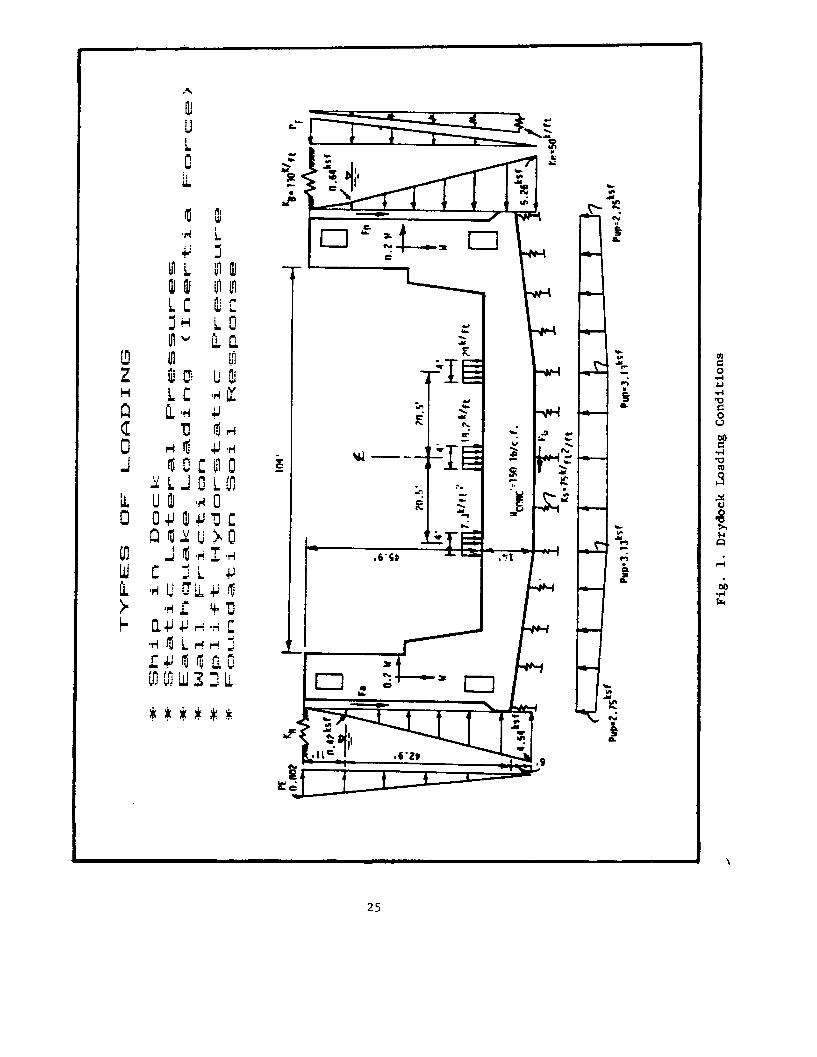
CASE S17 - Drydock Analysis, A. Wu
Problem: In the U. S., there are over 50 graving drydocks which need to becertified at a certain point in time. Naval shipyards are usually located inareas with unfavorable soil conditions. There have been many hydraulic fillswhich utilize uniform, fine sands which are subject to liquefaction. Thesedrydocks were mostly built during the past 20 to 50 years.
Loose, uniform, fine grained sands are subject to liquefaction when exposed toearthquake motions. Because of the upgraded seismic criteria, there isconcern about drydock failures resulting from soil liquefaction. In the eventof liquefaction, the drydock may float and/or tilt. Liquefaction alsocombined with high seismic inertia force may overstress or overturn thedrydock wall. All of these possibilities of failure are not acceptable to theNavy.
The drydocks need an adequate structural analysis. One obvious reason is thesafety requirements. A graving drydock is a stationary drydock which is builtbelow the ground surface. The drydock is used to maintain or repair the Navyships which include nuclear powered aircraft carriers or submarines. Theseismic criteria also has been upgraded recently and a higher seismic load isconsidered in the analysis. Absolute safety of the ship while in dock isnecessary.
Symptoms: Analysis indicating structural distress may occur under largeearthquake loads.
Collection of Facts:
The drydock can be classified according to the hydrostatic pressure conditionswhen the dock is dry. These are: (1) full hydrostatic, meaning that thehydrostatic pressure is acting both to the floor and to the wall; (2) fullyrelieved type, meaning that no hydrostatic pressure to the floor and wall; and(3) partially relieved type which has only hydrostatic uplift pressure actingto the floor.
22
The types of loading include ship weight, static pressures, and seismicforce. The soil-structure interaction, such as wall friction and subgraderesponse, are also included in the loading conditions.
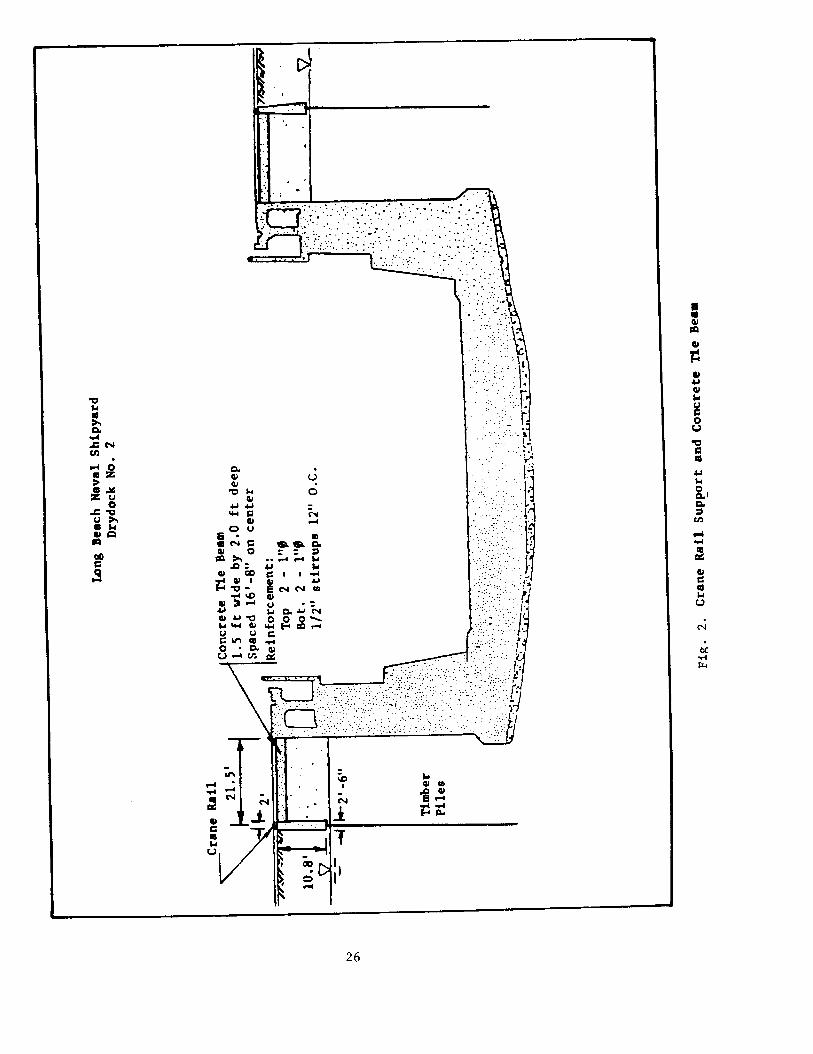
To analyze the effects of loading, we use some loading combination as shown inFig. 1. They may include ship load, different earthquake magnitudes, andlateral restraint provided by the crane rail tie beams which connect to thetop of the drydock wall. In most cases, we use six (6) combination cases inthe analysis.
Solution: An advanced and complete structural analysis using the finiteelement method was therefore implemented by the Navy. The analysis began withthe establishment of the structural and geotechnical parameters. Once thestructural configuration is set up by the structural engineer, thegeotechnical engineer develops the static loads, earthquake loads,soil-structure interaction, and the possible lateral restraint provided by theadjacent structures.
In most of the cases, the concrete tie beams which connect to the drydock wallmust be included in the analysis because of the lateral restraint to the walldisplacement and the added rigidity to the drydock wall. See Fig. 2.
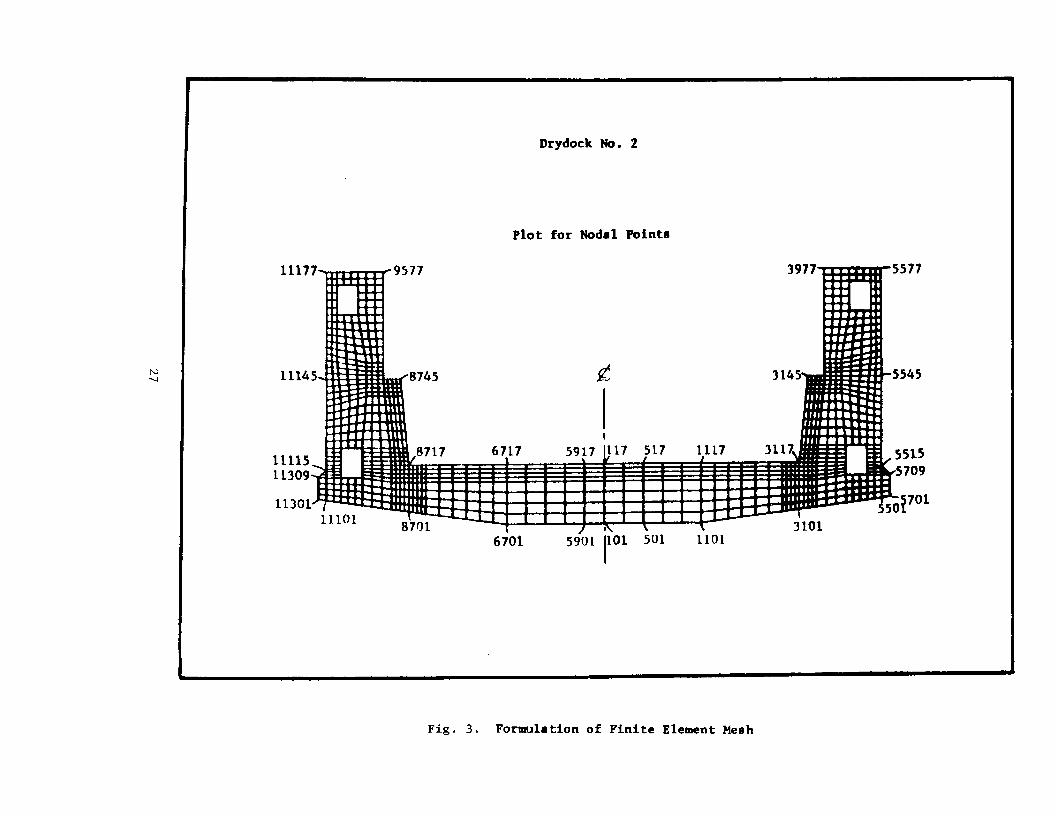
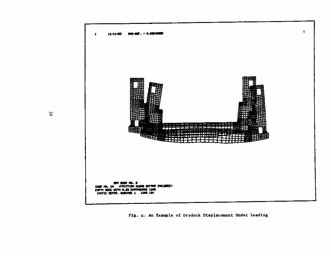
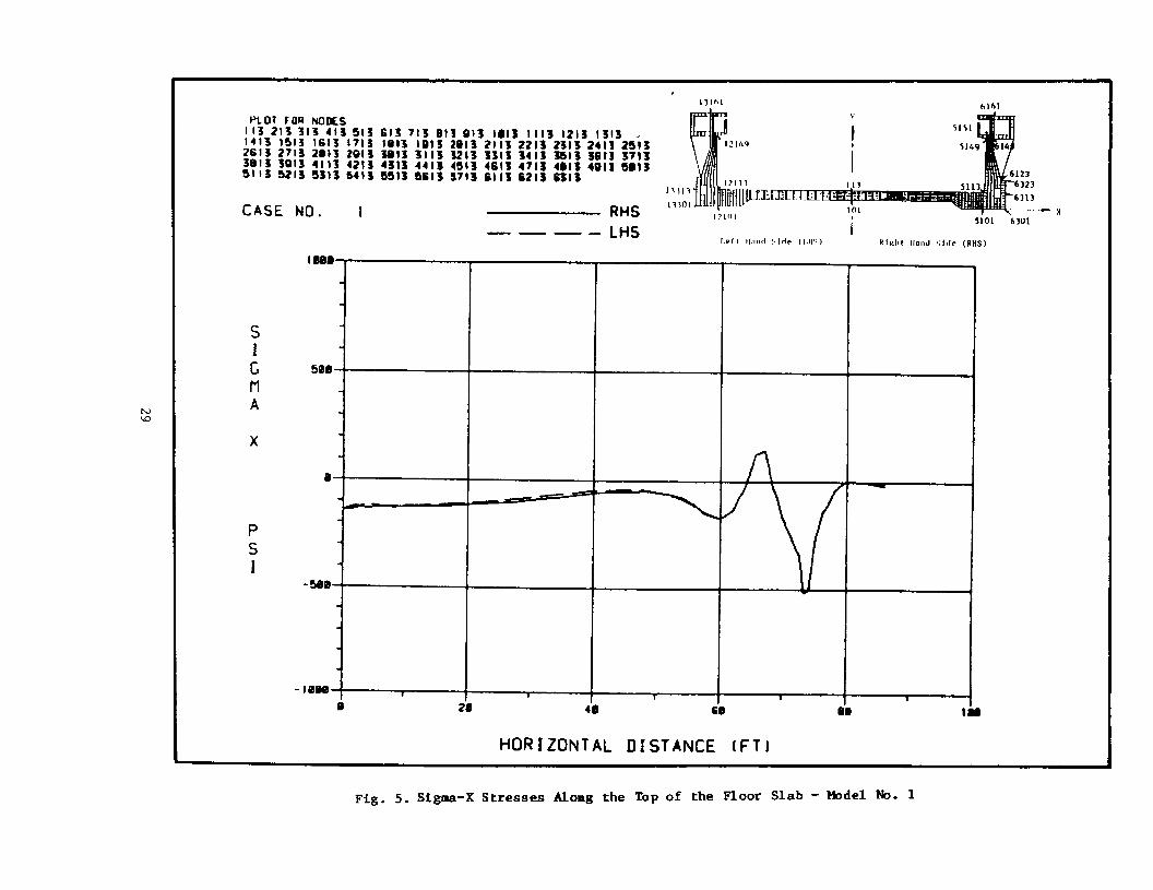
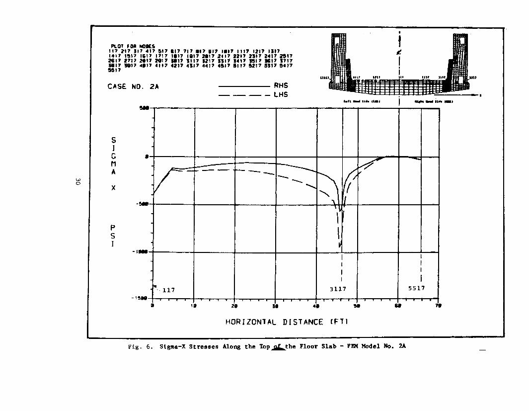
The numerical analysis is performed by the NASTRAN computer programs, whichare widely used in the Naval Ship Research and Development Center, inWashington, D. C. The first step of the analysis is to formulate the finiteelement mesh which is most suitable to the analysis. About six finite elementmodels, meaning six (6) loading cases, are generally selected for theanalysis. Some of the results are shown by Figs. 3 through 6. Fig. 3 showsthe formulation of a finite element mesh, Fig. 4 shows a displacement patternof the drydock subjected to a loading case, Figs. 5 and 6 show stress profilesof the floor slab.
From the experience of drydock structural analyses, we have learned that: (1)we cannot use the elementary strength of material concepts (i.e. f=My/Iequation); (2) we cannot use the equilibrium of free body concepts; (3) we canuse two dimensional finite element method, considering linear or non-linearmaterial properties; and (4) we may use Navy's earthquake loading criteria andcomputation. The method of computations are described in the Navy's designmanuals DM-7.2 and DM-7.3. The Navy's DM-7.3 discusses the factors affectingliquefaction and the empirical method of liquefaction potential evaluation.
The soil liquefaction problem during earthquake is still a great uncertainfield. Many difficulties arise when assessing the liquefaction potential.Some methods have been used, but the methods are still incomplete orquestionable. To evaluate liquefaction potential quickly, a simple flow chartis developed to check the problem, as shown on Fig. 7. The flow chart givesan idea whether a more sophisticated evaluation is warranted.
23

In conclusion, it was found that: (1) we can use geotechnical mechanicsprinciples to model the soil-structure interaction; (2) we cannot use
boundary restraint, (4) it needs adequate models to compare the results toassure the accuracy of the analysis; and (5) the last but not the least, thatthe analytical results must be checked by experienced structural andgeotechnical engineers. This is to assure that the results are dependable and
24
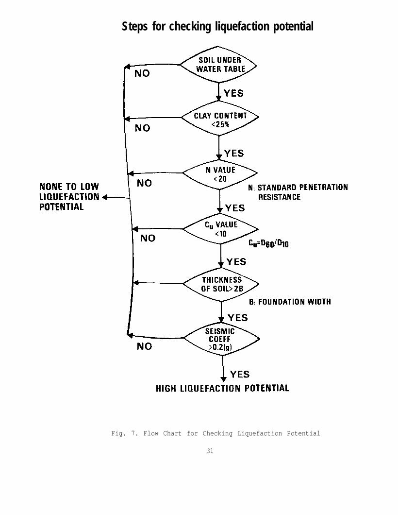
Steps for checking liquefaction potential
Fig. 7. Flow Chart for Checking Liquefaction Potential
31
CASE S18 - Concrete Repair, P. Malone
Problem: Failure of concrete patches.
Symptoms: The repairs made to concrete walls were not lasting a reasonablelength of time. Poor bonding to the old surface was apparent in most cases.
Collection of Facts: A review of the procedure indicated that not all thepersonnel involved in the concrete repair process were aware of the importanceof a clean rough surface as well as other factors in good concrete repairprocedures.
Solution: The engineering staff and the maintenance staff shall train thework crews before they are sent out to undertake repair projects on concrete.
32
METALLURGICAL
CASE ML1 - Weathering Steel, J. J. Cecilio
Problem: Failure of weathering steel ASTM A-690, A-588 and A-242.
Symptoms: Reoccurring cycle of rusting and flaking off under failure of thesection.
Collection of Facts: The copper bearing low alloy steels defined aboveCORRODE RAPIDLY IF NOT BOLDLY EXPOSED TO THE ELEMENTS OF SUN, RAIN AND WIND.These steels are marketed under ASTM A-690, A-588 and A-242. Their tradenames are Corten, Marten and Mariner. To prevent buildup of salt or othercontaminants during the wetting and drying cycle, any portions of a structurenot boldly exposed to the elements must be protected by painting or by theapplication of a barrier.
Solution: Structural elements made of weathering steel that may build upsalts and other contaminants shall be painted with a transparent varnish.Further information can be obtained from U.S. Steel Company.
ASTM-A-609 Mariner steel piling, wetting and drying portions should be blastedclean to near white metal and then coated by a 40 mil-carboglass 1601polyester glass flake. Source is the Carboline Company.
CASE ML2 - Use of Special Materials - Antennas, E. L. Mifflin
Problem: Selection of special high strength material.
Symptom: Contractors declined to bid on project.
Collection of Facts: A design for a tall tower utilized 90,000 psi heattreated alloy steel in order to reduce the size and weight of members. Thematerial required special welding specifications and resulted in a structurewhich contractors declined to bid on. There were only three well qualifiedpotential bidders and all initially declined to bid. Two bidders flatlyrefused to consider undertaking the project. The third bidder finally agreedto a negotiated contract. The use of the material selected increased the costby an estimated 2.5 million dollars and the total cost was undoubtedlyincreased because it was not possible to obtain competitive bids. Needless tosay, the negotiated price was not favorable to the government.
Solution: Investigate all aspects of cost and availability before usingspecial materials. Material that requires welding should be avoided for towerconstruction.
33
CASE ML3 - Galling of Sluice Gates, J. Cecilio
Problem: Galling of Sluice Gates
Collection of Facts: It was reported that the trim for the sluice gate ofDrydock No. 3 at Pearl Harbor was experiencing severe galling. The new sluicegate was trimmed with monel metal. Complete elimination of galling of theseating surfaces is very difficult to achieve. A survey of Naval Shipyardswas performed for evaluating galling of sluice gate which is as follows:
a. San Diego Naval Shipyard: Sluice gates, manufactured by Armco arecast iron with monel trim. Minor problems with galling.
b. Portsmouth Naval Shipyard: Sluice gates, manufactured by Rodney Hunt,are cast iron with bronze trim. The gates on one dock have no trim with castiron seating surfaces. They have experienced no galling.
C. Long Beach Naval Shipyard: Sluice gate cast iron with bronze trim.Some minor problems with galling. They repaired the trim on the gates of onedock by spray metalizing with bronze and remachining.
d. Puget Sound Naval Shipyard: Sluice gates, manufactured by RodneyHunt, are cast iron gates and frames trimmed with monel on one dock. Theyhave one set of gates yard-manufactured. They have experienced minor problemswhere the seating surfaces were of like material.
e. Norfolk Naval Shipyard: Sluice gates are cast iron trimmed as follows:Dock #2-cast iron with CUNI trim ASTM B-122 alloy 715; Dock #4-cast iron withphosphor bronze trim built by Armco-ASTM B-139 alloy 510; Dock #8-cast ironwith either monel or bronze. They have experienced no galling problem.
f. Mare Island Naval Shipyard: Sluice gates for two docks are cast ironwith the exception of those for Drydock #l which are stainless steel type 304purchased in 1958. Some galling has been experienced. One cast iron gate istrimmed with monel purchased in 1938. On this gate, some galling has beenexperienced. The gates purchased in 1938 are trimmed in bronze. Galling hasbeen noted on this gate's matting surface.
g. Newport News Shipbuilding and Drydock Company: On their docks forcarriers, they are using stainless steel trim. They are in the process ofreplacing the other gates at this time.
Solution: The following guidance was developed:
1. Like metals such as 400 monel to 400 monel may be successfully usedfor trim when the unit pressure from the water head is low-below 2,000 psi.
2. The normal surface finish should be 63 micro inches or better.
3.hardness
When pressure exceeds 2,000 psi, ARMCO used materials of differentialor dissimilar metal for the gate trim and the frame trim. As an
example, for high water head cover 2,000 psi it was common for one side of thesealing surface to be made of 304 stainless steel while the other side wasmade of Phosphor Bronze.
34
FATIGUE
CASE F1 - Connections of Struts for Grading Rings - Antennas, E. Mifflin
Problem: Failure of end connections of tubular struts supporting anti-coronaand grading rings.
Symptom: Connection failed.
Collection of Facts: Though the connection was eccentric, the calculated staticstresses were well within acceptable limits. Since the member was tubular,approximately three (3) inches round, aeolian vibrations were suspected.
Solution: A coiled cable was inserted in one end of the tubular member. Thecable was attached at that end and the end was sealed to the weather. Thiscable, which was slightly longer than the tube, damped any vibrations in thetube. No end connection failures have occurred since installation of the dampercable.
CASE F2 - Evebolt Failures - Antennas, E. Mifflin
Problem: Eyebolt failure in "fail safe" insulators.
Symptom: Eyebolts in compression cone "fail safe" insulators failed resultingin loss of guy support. Failures occurred in both types of connectors generallyused. One type a threaded rod with ball nut failed in the threads. The othertype failed at the junction of the shank and bolt head. (None failed in theeye). Bolts were in tension and bending.
Collection of Facts: Failures were initiated at cracks and/or areas of highstress concentration. First, a gradual fatigue failure developed until thecross section of the member was reduced sufficiently for a tension failure.Analysis of the bolt revealed very high bending stresses as well as the designtensile stress. The geometry of the area of failure is such that high stressesare generated at reentrant corners. The material is a heat treated forged highcarbon steel. (AISI numbers 1035 and 1040). In the threaded bolts, cracks werefound in the threads of some that had not failed. Improper weld repair toforged areas that were threaded also may have been a factor in initiating thefatigue crack. The Navy, Air Force and Coast Guard, as well as privateindustry, have many of these members in place functioning today. Replacement ofthem would be a very costly undertaking. In most cases, the failure of a guywould not endanger life.
Solution: In some cases, we have reduced the stresses by reducing tension inthe guys and consequently the likelihood of bolt failure. For the Navystructures where failures had occurred, the eyebolts were inspected and oneswith cracks were discarded. An investigation of a later failure at one siterevealed that for certain guys, the tensions had not been reduced and thefailure occurred at such a location. A completely new design for an eyebolt hadbeen developed and is in use. The metallurgy has been improved greatly for thisbolt. The geometry and stress level have been vastly improved also by having anupset threaded end and a special rounded thread. However, the originalmanufacturer has gone out of this business, and the other manufacturer hasdestroyed all of his casting and forging patterns.
35
CORROSION
CASE CR1 - Piping Corrosion, J. Cecilio
Problem: Building corrosion into your piping systems.
Symptom: High maintenance cost and early failure.
Collection of Facts: Define the purpose of the design. Define itsenvironment.
Solution: Use basic engineering design considerations to evaluate the designfor corrosion.
a. Design for easy cleaning and drainage.b. Design for easy component replacement where service failure is
anticipated.c. Avoid high localized stress concentrations.d. Avoid dissimilar metal contacts.e. Minimize or exclude air.f. Avoid heat transfer hot spots.g. Join by welding rather than bolts or rivets.h. Use smooth wide radius bends in piping systems.i. Avoid metallic contact with absorptive materials.g. Avoid high velocities.
CASE CR2 - Aluminum Corrosion in Wood, J. Cecilio
Problem: Corrosion of Aluminum in wood-aluminum assemblies.
Symptom: Corrosion of aluminum fasteners in fender pilings.
Collection of Facts: Corrosion of aluminum in wood-aluminum assemblies can beprevented by using well seasoned wood, coating aluminum with bitumen or otherelectrically neutral barriers and avoiding woods that produce a pH 5.0 orabove 7.O as well as bi-metallic action.
Solution: If aluminum fasteners are specified use bitumen paint or otherelectrically neutral barrier and avoid woods that produce a pH below 5.0 orabove 7.0.
36
CASE CR3 - Corrosion of Galvanized Guy Cables, E. Mifflin
Problem: Rapid corrosion.
Symptom: Corrosion and possible loss of strength.
Collection of Facts: Cables had a Class A galvanizing and were subject to avery hostile corrosive environment. To preserve longevity of the guys theyhad to be coated to resist rusting further. The cables range from one inchround to three and one eight inch round, and it is very costly to replace them.
Solution: A solution of on site conditions was to develop a coating mechanismand rigging to place a protective grease coating on the cables. For newconstruction, it is recommended that the designer specify a Class C galvanizedcoating on the outer wires of the cables. Life expectancy is three times thatof Class A.
CASE CR4 - Steel Conduit, T. Hayes
Problem: Rigid steel conduit installed on self-propelled craft.
Collection of Facts: The steel corroded at an accelerated rate.
Solution: Avoid steel conduit in a marine environment. Use PVC conduit.
CASE CR5 - Improper Ventilation in Sump Areas, T. Hayes
Problem: Improper ventilation in sump area of pumphouses and pump wellscauses rapid deterioration of mechanical equipment.
Collection of Facts: In the sump area of many pump wells, there is anaccumulation of moisture resulting from leaking, packing from drainage pumps,water seeping though the pump well walls and numerous other sources. Becauseof the damp condition that exists, mechanical equipment such as pumps, valvesand piping corrode at an accelerated rate. In most of these areas,ventilation is inadequate.
Solution: In the design of future pump wells, insure that adequateventilation is provided in the sump pit area.
37
CASE CR6 - Galvanized Piping System for Hyperbaric Systems, R. Johnston
Problem: Problem with Galvanized Piping System.
Symptom: Internal corrosion in piping system.
Collection of Facts: In the past, some L.P. air systems for hyperbaricchambers have utilized galvanized piping while performance has beensatisfactory. The use of trisodium phosphate (TSP) as a cleaning agent couldpotentially dissolve the zinc and leave the pipe vulnerable to corrosion.
Solution: Avoid galvanized piping on new systems. On existing systems ensurethat TSP is not used to clean the system.
Problem: Corrosion of Mariner Steel Fender Piling
Collection of Facts: The 132 H steel piles located at the Trident Wharf areeighty feet long and conform to the HP 14x102 shape. The material specifiedis of the ASTM A690 chemical composition and is commonly known as MarinerSteel. These pilings were driven into clay bottom approximately twenty feet,The remaining sixty feet includes forty feet in the immersed zone and thefinal twenty feet above water. Tidal fluctuation in the basin causes aboutfour feet of the pile to be alternately wetted and dried twice daily. Thepiles have been in place since the facility was built in 1975.
Portions of the piling subject to tidal fluctuations sustained the mostdamage. Close observation revealed that 1arge sheets of corrosion productwere easily removed exposing pitted steel underneath.
Measurements were made to calculate percent reduction in thickness offlange and corrosion rate of the H piling. The corrosion product was firstchipped off and then scraped to reveal the underlying steel for obtainingaccurate measurements. In addition to the uniform corrosion, many severe pitswere observed with depths estimated at 50 mils (0.050") or more. The pitdepth would be subtracted to determine the resulting thickness at the H pilingHP 14x102 AST, A690.
Flange thickness before corrosion 0.704”Flange thickness after corrosion 0.550”Decrease in thickness due to pitting 0.050”Resulting thickness at area of pit 0.500”
Percent reduction due to corrosion (at area of pit):
Therefore, in four years of services, 29% of original material has beenlost due to corrosion.
38
Case CR7 - Mariner Steel Fender Piling, J. Cecilio
Corrosion rate (inches penetration per year):
(0.704”-0.500”)/4 = 0.051 ipy
51 mils/year (1 mil = .OOl inches)
Subsequent to thickness measurements, a detailed diver report andphotographs were made. The diver inspection included observations starting atthe surface and concluded at the mud line. Below water, the surface conditionchanged and was observed to be covered by a soft powdery corrosion productthat was black in color. This film was easily removed to reveal theunderlying steel which seemed in good shape. This condition persisted all theway to the mud line indicating uniform corrosion beneath the water. Althoughno thickness measurements were made below water, the divers indicated thepiling appears to be sustaining leas damage below water than in the tidal zone.
Solution: The corrosion rate and damage to the pilings was unacceptable. Twomethods were recommended to control the corrosion rate:
a. The system providing the best protection was a near white blast ofthe steel followed by a 40 mil coat of carboglass 1601 polyesterglassflake manufactured by Carboline Company. Several other coatingsystems performed well, but the glassflake received the highest evaluationin the atmospheric, immersed, and sand-swept zones. The system alsoprovided excellent abrasion resistant and would hold up to the abrasionproduced by the camel mooring system used for the submarines. The problemwith using this system would be the cost of removing and reinstalling thepilings. However, this would be protection recommended for any fenderpile system during initial construction or installation.
b. A second method that would afford protection could be applied withpilings in place. It is a system of epoxy encasement of the steel pilingin the tidal zone. A fiberglass form is placed around the piling and theepoxy mortar is poured to seal out the corrosive environment. The firmthat provided this information is Logan Engineering Contracting Company inJacksonville, Florida. Since encasement of the piling all the way to themud line would be extremely expensive, catholic protection could be usedin conjunction with this system to yield acceptable results. However,there is no documented corrosion performance data available on thisencasement system.
39
WELDING & NON-DESTRUCTIVE TESTING
CASE W1 - Distortions in Welded Structures, J. Cecilio
Problem: Structures such as POL tanks and radio shielded rooms require largeareas to be covered by steel plates and connected by welding to insuretightness. These facilities require a great deal of planning, preparation,and care in fabrication to insure proper fit and to minimize warpage anddistortion.
Collection of Facts: When improper welding methods are used excessivebuckling and warpage occur requiring additional rework and increased cost.
Solution: Distortions and warpage in welded plates can be minimized andsatisfactory results can be obtained, if the proper methods are used.Distortion and warpage can be minimized by adherence to the following:
a.b.c.d.
Don't overweld.Control fitup.Use intermitted welds where possible.Use the smallest size of weld permissible.Use minimum root opening, including angle and reinforcement.Select joints that require minimal weld metal, for example, adouble "V" joint instead of single "V" joint.Weld alternately on either side of the joint when possible withmultiple pass welds.
e.f.
h.i.
j.
k.
l.m.
n.o.
p.
s.
Use fewer weld passes/ high deposition rate.Use higher speed welding methods (iron powder coated electrodesor mechanized welding, etc.)Use welding methods that give deeper penetration and thus reducethe amount of weld metal and heat needed for the same strength.Use welding positioners to achieve maximum amount of downhandwelding, allowing the use of larger diameter electrodes or higherdeposition rate welding procedures with faster welding speeds.Balance welds about the neutral axis of the member.Distribute the welding heat as evenly as possible through plannedwelding sequence and weld position.Weld toward the unrestrained part of the member.Use clamps, fixtures and strongbacks to maintain fitup andalignment.Prebend the members or preset the joint to let shrinkage pullthem back into alignment.Weld those joints that cause the most contraction first.Weld the more flexible section first so they can be strengthened,if necessary, before final assembly.Sequence subassemblies and final assemblies so that the weldsbeing made continually balance each other around the section'sneutral axis.
40

CASE W2 - Acceptance & Inspection Criteria. J. V. Tyrrell
Problem: Inspection & Acceptance Criteria
Collection of Facts: Often disputes arise over whether or not an item meetsthe contract requirements. This is particularly true where performancespecifications are used. However, it also is a problem for contracts whereexplicit specifications are used. Some of the common causes are: conflicts orerrors in the plans and specifications, vagueness, insufficient, definition,reliance on references to standards or codes without knowing enough abouttheir content, failure to state essential inspection requirements (methods andtiming), failure to specify how acceptance tests will be evaluated and howdeficiencies are to be resolved, deviations from plans or specificationspermitted by field personnel without design consultation.
One example of such a dispute involved welding of a gas cooler for a jetengine test cell. This unit was designed for both positive and negativepressure and for temperatures ranging from minus 67 degrees to 3500 degreesfahrenheit. The specification required radiographic inspection of welding inaccord with Section 8 of the ASTM Pressure Vessel Code.
The referenced code, at that time, required a sampling of welding and,where defects were found, the sample was to be extended a certain distanceeach side of the original sample. Then all the defective areas were to beremoved and rewelded. Under this code, unacceptable defects included cracks,lack of fusion, and incomplete penetration. There was no standard forporosity.
When the welds were examined, the laboratory performing the inspectionrecommended rejection of 95% of the sampling. Most of the welds contained allthe defects listed, however, about 20% were cited principally for porosity,undercut, and other things not specifically covered in the referenced code.On the basis of these results and to avoid delay in construction, the ResidentOfficer in Charge of Construction ordered radiographic inspection of thewelding. This resulted in repair of over 90% of the welds.
The contractor subsequently claimed that some welds were rejected thatwere actually not unsatisfactory according to the specification. He alsoclaimed that if the inspection procedure specified had been followed, somewelds containing defects would have been accepted. The government assertedthat it had the right to extend inspection under the general provisions of thecontract and that the rejected welds all failed to show acceptableworkmanship. In the end a compromise settlement was reached, but thecontractor got the lion’s share.
Solution: There is no sure way to avoid all the pitfalls which are inherentin design and construction. It helps to know the content of referencedmaterial particularly for important, unusual, or complex construction. Itis, of course, necessary to thoroughly check the plans and specifications andconsider the possible need for a constructibility review. Also think aboutthe things that you do not want as well as those that you intend to have inthe finished product, and how a third party would evaluate the constructionagainst the contract documents. Always make sure that the acceptance criteriais clear.
41
CIVIL
CASE C1 - Industrial Waste Treatment & Electroplating Facilities, L. Wernigg &J. Yacoub
Problem: The Navy is operating a large number of industrial waste treatment(IWT) and electroplating (EP) facilities with varying degrees ofeffectiveness, with several plants having difficulties meeting effluentlimitations and having excessive operations and maintenance problems.
Symptom: Several IWT plants do not meet toxic heavy metal dischargerequirements imposed by Federal and State regulatory authorities (Nov. 1984).Furthermore, there are serious problems with inoperative instrumentation andcontrol systems, with excessive maintenance requirements for some of theinstalled equipment and other difficulties.
Collection of Facts: A review of the project histories of several IWT plantsand electroplating shops and post-occupancy evaluation reports revealed thatproblems are not reducible to one or two major causes. They derive from awide range of factors relating to preliminary engineering studies, thegovernment contracting process, A/E selection, design, project funding,construction inspection, staff selection and training, changing environmentalregulations, high rate of inflation of the 70's, and the very nature ofindustrial waste control itself.
Solution:
Background: Under the Post Occupancy Evaluation Program, four IWT and oneEP facilities have been evaluated to date. These IWT facilities are locatedat: NWSC Crane, NAS North Island, NAS Jacksonville, and NARF Norfolk. The EPfacility is at Norfolk NSY Portsmouth, VA. An additional IWT facility atMCLSBA, Albany, GA had a detailed review prior to including IWT in the POEprogram.
These evaluated facilities represent twelve years of project planning andacquisition efforts. During this period of time, the country progressed fromdumping (to oceans, streams, lakes or land disposal sites) much of itspollution generated at industrial facilities to collection and treatmentplants to meet very strict Federal and state discharge criteria. As a directresult of the Federal Laws and Executive Orders mandating this major change, alarge number of projects were initiated to implement these requirements. Allof this happened at a time when we were not staffed to handle the planning,design, construction and operation of these facilities. The A/E community wasalso unprepared.
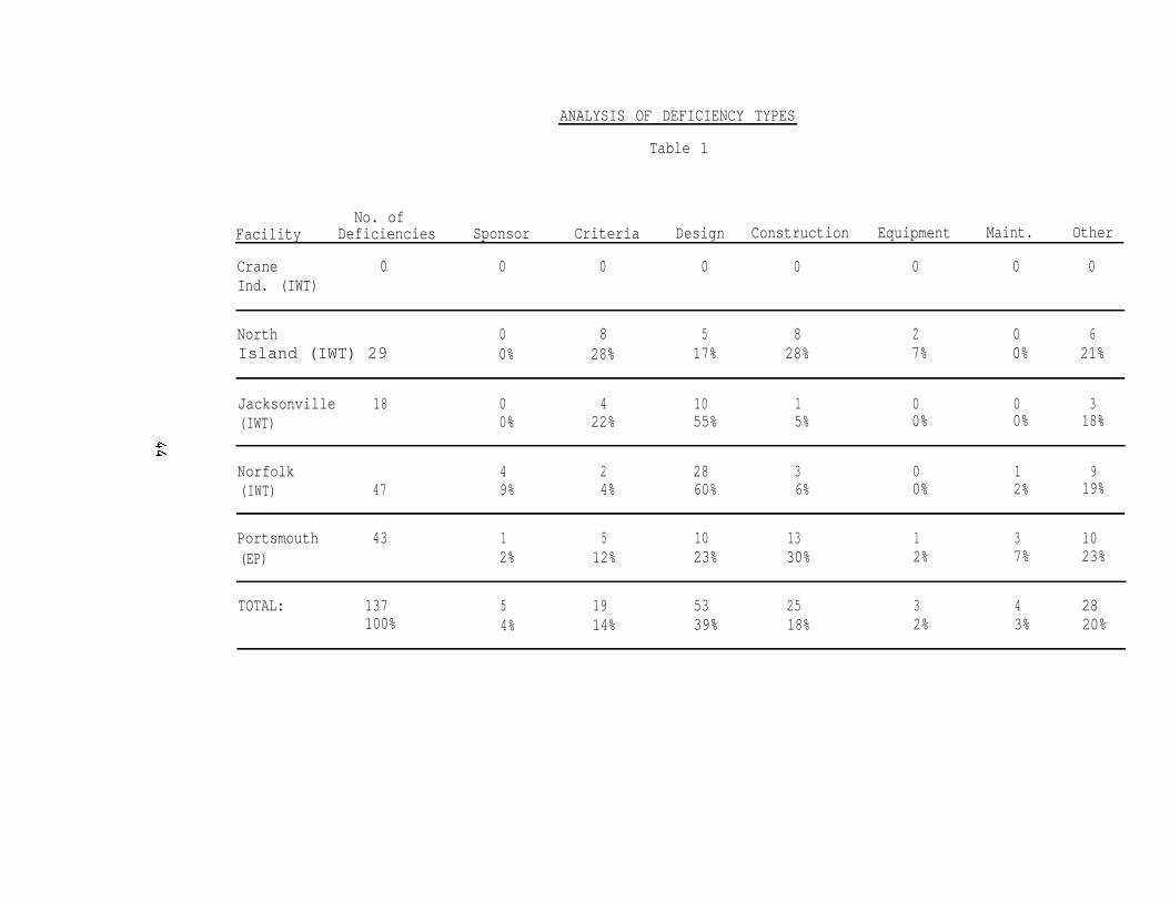
Summary of POE Findings: Table 3 on page 44 provides an analysis ofdeficiency types for five post occupancy evaluations conducted in theindustrial waste treatment and electroplating category. All of these IWTplants are first generation or upgraded first generation plants, thereforeidentifying trends would be premature. In addition, one of the POEs, atCrane, was unique, because basically it was designed, built and operated byone small private firm. Because of the operation by a private contractor, itwas difficult to evaluate it on the same basis as a Navy-run facility.
42
The majority of the deficiencies (39%) are design deficiencies. Asmentioned earlier, most of the consulting engineering firms hired to designthese facilities were inexperienced in this field. Even when a second A/E(consultant) was hired to critique the design A/E's submission (NARF, Norfolkproject), the majority of the deficiencies were still design related. Thisshows how important it is to select a highly qualified firm to design thesefacilities.
The next highest categories of deficiencies are related to construction(18%) and design criteria (14%). Adequate design criteria is lacking in theexisting DM 5.8 Pollution Control Systems. However, it is being revised, witha probable project completion of June 1985. In addition, electroplatingdesign criteria is under development.
The construction of some of these complex facilities has been a problem.These projects require close inspection and careful control of material andequipment substitution change orders. Title II inspection procedure, usingthe design engineers or another engineering firm, should be requested by theEFD. Also, equipment acceptance tests should be coordinated with the designA/E and EFD.
Based on the lessons learned on these projects evaluated under the POEProgram and some others evaluated previously, Guidelines for IndustrialFacilities Projects (Encl (1) to NAVFACINST 4862.5B) were prepared. Theseattachment (1) guidelines should be followed from the initial conception ofthe project in the planning stage through design, construction, shake-downperiod, monitoring and certification.
43
ANALYSIS OF DEFICIENCY TYPES
Table 1
No. ofFacility Deficiencies Sponsor Criteria Design Construction Equipment Maint. Other
Crane 0 0 0 0 0 0 0 0Ind. (IWT)
North 0 8 5 8 2 0 6Island (IWT) 29 0% 28% 17% 28% 7% 0% 21%
Jacksonville 18 0 4 10 1 0 0 3(IWT) 0% 22% 55% 5% 0% 0% 18%
Norfolk 4 2 28 3 0 1 9(IWT) 47 9% 4% 60% 6% 0% 2% 19%
Portsmouth 43 1 5 10 13 1 3 10(EP) 2% 12% 23% 30% 2% 7% 23%
TOTAL: 137 5 19 53 25 3 4 28100% 4% 14% 39% 18% 2% 3% 20%
Analysis of Findings: To view these projects from the rightperspective, the project POE teams looked at not just the deficienciesidentified during the POE of the project, but the whole project history.Same of the major problem areas identified are described here.
o Cost Analysis: It appears, that the single most troublesomefactor causing problems in these facilities is theunrealistically low cost estimate made in the early stages ofthese projects.
For example:
NARF, Norfolk IWT Plant:Originally Programmed: $1,009,000Spent on Original Plant: 2,100,000Upgrade Cost to Date: 5,200,000
Total to Date: $8,309,000
MCLSBA, Albany, GA IWT Plant:Planning Study Cost Estimate: $ 253,000PCE Cost Estimate: 383,000Designer Estimate: 457,000Contractor Takeoff: 700,000Low Bid: 926,000*
* After eliminating key elements of the plant, such as equipmentredundancy, laboratory and office space.
When we underestimate the cost by a factor of four, we are actuallyasking the A/E to design the facility for 1 1/2% of the project cost when6% is allowed and still unrealistic. In private industry, the design costof an IWT plant is often 10-15% of the project cost.
o Automation
One persistent technical problem, common in many Navy facilities,needs to be singled out. It is the degree of automation providedin the system. The rationale for a high degree of automation isusually that it reduces operator requirements at the plant. Asindicated in the lessons learned part of this report, just theopposite appears to be the case. It was found at government andprivate industry facilities, that computerized control systemsare costly, require constant attention, constant maintenance, andconstant trouble shooting. Highly paid specialists are necessaryto maintain both control and data-acquisition systems. A verycommon source of failure is the instrumentation that feedsprocess data to the computer. Therefore, total automation shouldnot be attempted. What is needed is to automate (with completemanual back-up) time-consuming tasks, such as opening and closingvalves, monitoring pH, ORP, change in pressure, operation ofchemical feed systems, etc.
45
o Metal Recovery in Plating Shops
One means of environmental control which the Navy has attemptedto use on its hard chrome electroplating lines is asub-atmospheric evaporative recovery unit. Simply stated, theunit is designed to recover chrome from the plating process andreturn it to the plating bath for further use. The Navy's firsttest evaluation took place at NARF Pensacola. The experienceprovided NAVFAC with valuable insight concerning the installationof environmental controls within a production shop. Among thelessons learned:
o If an environmental control requires attention fromproduction personnel, the Navy must have an up-frontcommitment from management that personnel will be dedicatedto the task.
o If environmental controls require changes in productionmethods, expect resistance. The Navy must demonstrate thatthe "new way" will benefit production as well as theenvironment.
o The production side of the Navy does not necessarily feeldirect responsibility for environmental protection. Many,though not all, Navy activities are shielded from the Navy'senvironmental requirements by public works departments and afinancial structure which does not always recognizeindividual liabilities/responsibilities. For example, anactivity can cause a Navy treatment plant to violate aneffluent standard. However, even if the Navy pays a fine,the public works department accepts responsibility, and theactivity is not held liable.
The Navy has reinstalled the equipment at Charleston NavyShipyard. At this time, the unit is functioning on theshipyard's chrome plating line, and is returning chrome to theplating bath. Since the unit is functioning, we have been ableto evaluate its applicability and economic impacts. Preliminaryresults indicate the following:
The unit requires regular operator attention. We have hadto replace worn valves, gaskets, and seals, and the SouthernDivision has developed a preventive maintenance and spareparts inventory to minimize down time.
The equipment appears to be economically unjustified, due inpart to the relatively small amount of production at Navyactivities, and the remaining need for end-of-pipe treatmentfor other wastes.
The availability of simpler, less expensive systems toachieve improved production and enhanced environmentalcontrols.
46
In summary, the Navy's first attempt at metal recovery in a platingshop, though unsuccessful, did pave the way for future installation ofalternate environmental systems. The Navy is now installing alternatesystems in NARF Jacksonville, and is planning to install them in newplating shops.
o Design. Often, as indicated earlier, the design of thesefacilities has not been totally satisfactory. It appears thatthis problem is often caused by the practice of hiring A/E firmswithout relevant experience. Therefore, we recommend that theEngineer qualification-A/E selection process described inattachment (1) be closely followed on IWT and EP projects.
Lessons Learned:
The following paragraphs summarize lessons learned from previousprojects that need to be considered for all future projects. Theselessons learned have been grouped into five categories: design factors,operational factors, equipment selection, material selection, andmanagement.
1. Design Factors. The following points should be considered:
a. Effluent discharge limits set by regulatory agencies shouldbe evaluated closely and renegotiated with the issuing agency (ifthere is sufficient justification) prior to proceeding onfacility plant design.
b. Treatment operational requirements should be kept as simpleas possible. Use instrumentation and controls only to reduceoperating manpower requirements or hazard exposure. Highlyautomated control systems have not been successful at Navyfacilities. The degree of automation should be optimized bybalancing specific project factors. For example, a highlyautomated system which requires a few well-trained operators andconsiderable instrument maintenance must be compared against asystem with less automation but greater operator attention. Thedegree of automation must reflect the specific Navy facilitiesstaffing capabilities. In most instances, this will includeautomatic feed system, motorized valves, and other systems whichminimize relatively simple treatment tasks.
c. Operational considerations must be closely coordinated withwaste treatment plant design in order to achieve an efficient andreliable facility.
d. Collection sewers, pumping facilities, and all treatmenttanks for acids and cyanides should be located completelyseparate from each other to avoid mixing and severe safetyhazards. Facilities should be separate and designed so thatspills or leaks could not result in cross connection between theacid and cyanide operations.
47
e. Leakage of industrial wastes or sludges from any container orvessel such as tanks, pipes, or sand drying beds must beavoided. Emergency drains and spill containment area drainsshould be provided.
f Waste treatment from plating operations should providesufficient on-site storage capacity to allow for a minimum ofeight (8) hours of plating operation during waste treatmentshutdown periods.
Ventilation design must provide adequate air flow duringnormal and emergency conditions to assure a safe environment foroperating personnel. This is particularly crucial in plant areasthat generate chemical fumes and vapors. Covers for large volumereactors and equalization basins should be considered.
h. Provide positive head on all pump suctions.
i. Particular caution should be observed with chemical pipinglayout; for example, avoid entrapment areas for hydrogen peroxidewhich may cause valve and pipe eruption. Provide vacuum breaksin piping design to avoid undesirable back siphonage to pumps andtanks.
Provide adequate design of piping and equipment supports toavoid vibration which may lead to failure.
k. Provide for storage of process treatment chemicals intemperature controlled area.
l. Consider use of pneumatically controlled valves (rather thanelectric) in corrosive environments.
m. In the future, a much tighter and much more detailedspecification for scrubbers and demisters is required to avoidnaming manufacturers. The specifications should include thefollowing:
o Requirement for packed tower type not for cross flow
o Requirement for minimum scrubber packing depth
o Requirement for minimum demister pad depth
o Maximum static pressure drop for scrubbers and demisters
o Requirements for access manholes for inspection andmaintenance
o Liquid to gas flow rate
o Recycle water flow
48
o Sump size
o Spray nozzle location and size
o Reference to IGCI (Industrial Gas Cleaning Institute)Guideline Manuals for scrubbers and demisters
n. Design criteria for electroplating shop layouts, tankdesign, ventilation system design, etc. are badly needed.In-shop source control (segregation, recycle, reuse and goodhousekeeping) must be a major part of the design criteria.A design that facilitates maintenance and good housekeepingis very important.
2. Operational Factors. The following points should be considered:
a. Adequate operator training at facilities is mandatory. Anoperation and maintenance manual which specifically reflects theplant's requirements is also necessary. On-the-job trainingshould be conducted at plant's startup and continued until theentire treatment process runs continuously and satisfies effluentdischarge criteria.
b. Operation and maintenance manuals should be prepared for eachequipment component in the plant. A system O&M manual should beprepared to integrate and demonstrate how each component relatesto the system. Operation and equipment manuals should be updatedafter performance demonstration period to include equipment andplant modifications and new operational requirements implementedduring startup or performance demonstration period. Contingencyplans should be developed for plant shutdown and chemical spills.
c. Plant equipment should be operated immediately uponinstallation. Equipment should not be allowed to sit idle anddeteriorate from lack of usage. Equipment performance should bein demonstrated compliance with specifications and testingprocedures.
d. Operator work requirements should be minimized by designingfor use of treatment chemicals in liquid form to be pumped orpowder form to be automatically fed.
e. Use of computer control systems with total manual backupshould be considered for larger installations.
f. A steam line/wand, or air supply, should be provided forcleaning filter press gaskets and flanges after removing solidsfrom the units.
g. There is no reason for periodic dumping of plating baths.Normal contamination can be filtered out. The only way iron willcontaminate a bath is when the current is reversed on the part
49
being plated causing dissolution. That should never happen. Forexample, a chrome bath contaminated with iron can cost $20,000 toreplace. In addition, the solution is highly toxic requiringspecial costly disposal, and chrome is a resource that isdifficult to obtain.
3. Equipment Selection. The following points should be considered:
a. For solids separation following chemical precipitation(particularly plating waste), parallel plate or tube separatorsshould be evaluated. Means of cleaning plugged plates or tubesmust be provided.
b. Plate and frame filter presses have been particularlysuccessful for dewatering chemical sludges for direct disposaland should be used unless special circumstances dictate otherwise.
c. Electrically powered agitators are preferred over airspargers. Mixer shafts should be constructed of solidcorrosion-resistant materials rather than coated.
4. Material Selection. One of the most critical factors that hascaused unfavorable conditions at industrial waste facilities operated bythe Navy has been material selection and/or protection from the corrosiveenvironments. Careful selection of materials is necessary. The followingpoints should be considered:
a. Concrete block or masonry buildings are preferred over steelto resist corrosion.
b. Exhaust and ventilation ductwork must be structurally sound.Ductwork must have the proper materials to resist corrosive fumesvented or a corrosive atmosphere on the exterior side.
c. All piping and conduit material should be resistant to thecorrosive agents and operating conditions to which it may beexposed. All exposed metal which is nonresistant to corrosionmust be painted with a corrosion resistant paint. Effect ofcorrosive atmosphere on building interior roof and walls must beconsidered.
d. Tank materials (or liners) should be of proper corrosionresistant material.
e. Materials for seals, connectors, and gaskets on piping andpumps exposed to corrosive materials should be carefully selectedto avoid damage.
f. All pump housing should be corrosion resistant.
g. All overhead piping which carries corrosive-type materialsshould be provided with a corrosion-resistant sleeve and directedto a safe area to avoid safety hazards from 1eaky piping.Provide emergency area floor drains.
50
5 l
h. Proper welding specifications and materials are necessary forconstructing and/or repairing tanks and equipment which areexposed to corrosive materials.
i. Electrical boxes should be located away from corrosiveenvironments. If located in corrosive operating areas, theyshould be sealed gasket types and corrosion resistant.
j. All other instruments and electrical equipment which may beexposed to corrosive environment should be protected. Controlconsoles, panel-boards, and transformers should be located withina closed and vented control room out of any corrosive atmosphere.
k. Concrete tanks or sewers exposed to corrosive materialsshould be constructed of acid-resistant concrete or provided withsuitable liners.
Management. The following lessons should be considered:
a.
b.
c.
d.
An electroplater's job, of considerable complexity, is a lowpaying job requiring constant handling of hazardous andtoxic substances in a hazardous environment. These platers,after taking considerable training on government expense,often leave their jobs for better paying positions.Therefore, it would be an advantage to the government toupgrade the job description and pay of the electroplatersthat would result in a lower turnover rate; people with moremotivation would stay in these jobs who would be more likelyto comply with the important energy conservation andenvironment protection guidelines; and would reduce trainingcost.
In locations like an electroplating shop, the ventilationand lighting systems, and shop machinery create a very noisyenvironment. Therefore, there should be a noise abatementstudy as part of the Preliminary Engineering Study (PES).
Title II Inspection is not always the answer to inadequateinspection. There is always a chance that an unqualifiedperson may be assigned to the job, or high turnover ofpersonnel provides no continuity. It may be better to getthe designer or project consultant to inspect the projectconstruction on a once or twice a month basis and, in caseof an upgrade project, to keep in touch with the operatingpersonnel. As it was demonstrated on Norfolk NSYelectroplating project, it pays to have good coordinationbetween the electroplating consultant and operatingpersonnel.
Repair and maintenance of an electroplating shop during thefirst year of operation can be a major problem. Often,complex and costly equipment, will not get the necessaryadjustment, calibration, lubrication and repair because it
is "under warranty". There is an attitude that themanufacturer is responsible to take care of this equipmentduring the first year of operation. Therefore, it isrecommended that at least one mechanic be permanentlyassigned to the plating shop for preventive maintenance andrepair. Also, the platers should do some of the simplemaintenance tasks during low production times.
e. Because of recent major advances made in outfitting ofelectroplating shops and because of these shops handlinghazardous and toxic materials to some very strict newregulations, "old" plating shops should not be upgraded.They should be replaced instead with new state-of-the-artdesigns.
f. For future plating shops, the type of air pollution controlequipment and the degree of air pollution control must beaddressed by the Navy. Since federal and state regulationsdo not address specific emissions limits for plating shops,the navy must direct the design engineer as to the level ofcontrol. NAVENENVSA Code 111C has recent stack tests fromLong Beach Shipyard plating shop, which will help withidentification of the quantity and quality of air emissionsto decide the level of air pollution control for specificplating lines.
Conclusion: It is evident from the above that the acquisition ofIndustrial Waste Control Facilities and Electroplating Facilities has beena difficult process. To improve our record, the following is recommended:
1. Follow the Guidelines for Industrial Facilities Projects of:NAVFACINST 4862.5B.
2. Consider innovative acquisition routes, such as:
a. Design, build and operate by contract.
b. Request technical proposals from highly qualified firms.Accept bids only from those firms which submitted approvedproposals.
3. Consider all the lessons learned, as summarized here.
4. Use the revised DM 5.8. For pre-publication copies, contact CodeO4Bd, NAVFACENGCOMHQ.
5. Pay attention to detail:
52

Category Code of Facilities Affected:
831-09 211-14831-14 211-24831-15 211-31832-30 211-41832-40 211-51227-35 211-61213-49 211-73
Keywords:
Industrial waste, automation, control, design, operation, material,selection, material recovery, electroplating
53
NAVFACINST 4862.5B
GUIDELINES FOR INDUSTRIAL FACILITIES PROJECTS
I. INTRODUCTION
References: (a) NAVFACINST 11010.44D(b) CNO ltr Ser 454C/34394544 of 14 Dec 1983(c) NAVFACINST 5100.11E(d) NAVFACINST 11010.32F(e) NAVFAC DN-5.8(f) NAVFAC DM-3.15(g) MIL-H-46855B(h) NAVFACINST 11010.14N(i) NAVFAC P-68(j) NAVFACINST 11013.39
A. INDUSTRIAL FACILITIES
Construction projects at shore facilities are initiated by theactivities. The early investigations and preliminary engineering studiesto define the needs and provide documentation for the Facility Study andDD Form 1391 development are the responsibility of the activity and itsmajor claimant. From this point, after the project is included in aspecific fiscal year program, Naval Facilities Engineering Command(NAVFACENGCOM) takes over and carries it through design andconstruction. After construction is complete, the facility is turnedover to the user. This typical procedure proved to be inadequate for themore complex industrial projects. Therefore, to better serve the needsof the facility users, to ascertain that all aspects of the project areconsidered and to ensure that the facility is functioning as intended, amodified approach will be followed for industrial projects which involvecomplex processes or hazardous/toxic materials subject to regulation.This modified approach is described in the following guidelines. For aschematic, showing the sequence of events for projects which involvecomplex processes, see Figure 1.
B. These guidelines are intended for MCON projects; however, theyalso can be followed for non-MCON projects. The described team approach,with representatives from the activity, Engineering Field Division (EFD)and NAVFACENGCOMHQ, if needed, will be implemented. In addition, a fewkey projects, identified by NAVFACENGCOMHQ, will either be reviewed atNAVFACENGCOMHQ, or by a formally established acquisition team. For theseprojects, the guidelines provide submission requirements.
C. NAVFACENGCOM will execute a Memorandum of Understanding (MOU)with claimants to identify management procedures, specific projectresponsibilities and coordination procedures to be followed. As part ofthe MOU, the claimants will notify NAVFACENGCOM at a very early stage ofthe projects addressed here to allow the formation of the project teamsafter submission of Preliminary DD Form 1391 and inclusion of the projectin the 5-year program. The formation of these teams and scheduling thepreliminary engineering studies are EFD responsibilities. The majortasks of the project teams are shown on Figure 2. Also, this figure canbe used to keep track of each project until completion.
Attachment (1)
54
NAVFACINST 4862.5B
D. Certain projects may not require or lend themselves to all of theprovisions described below. Where doubt exists, guidance should besought from NAVFACENGCOMHQ, Code 04B.
II. TECHNICAL CONSIDERATIONS
A. PRELIMINARY DD FORM 1391 SUBMISSION
The Preliminary DD Form 1391 Submission (PRELIM 1391) identifiesand describes facilities required in support of an activity's assignedmission. The PRELIM 1391 is a predecessor of the 1391/Facility Studysubmission. The project submission includes the Preliminary DD Form 1391and Supplemental Sheets (1391C) to provide essential Shore FacilitiesPlanning System (SFPS) and programming information required for review,certification and entry of the project into the Military ConstructionRequirements List (MILCON RL). There are five additional components inthe Preliminary DD Form 1391 Submission package. They are the pertinentFacility Planning Documents, an Economic Analysis, a site plan, anenviromental review and a cost estimate. See reference (a) series forguidance on the preparation of the PRELIM 1391 as well as on the criteriaused in its validation for entry into the MILCON RL.
B. PRELIMINARY ENGINEERING STUDY
1. Close internal coordination on projects dealing withhazardous/toxic materials is essential. Therefore, beginning withdevelopment of a Preliminary Engineering Study (PES), which is required,a "team" concept shall be implemented. Members of the team shall bethe activity, EFD, and, if necessary, NAVFACENGCOMHQ. Timely review ofall project documentation by these team members is essential. As aminimum, codes familiar with design, construction and environmentalregulations must be included as project team members.
2. After selection of project team members, the EFD shallconduct a PES for project definition and basis of design. A PreliminaryHazard Analysis (PHA), as required by reference (b), "System SafetyEngineering for Facilities Acquisition", is to be conducted concomitantlyand in conjunction with the PES. The PHA shall be considered as part ofthe PES. The PES, including the PHA, is a critical step in identifyingand documenting deficiencies and problems and in developing firm costestimates and viable alternatives. Timeliness is of the essence, sinceit will provide information needed for development of Form 1391.
3. As part of the PES,given to source control,
it is essential that consideration beincluding the possibility of substantially
altering a process or plant operation to reduce pollutant loading. Byreducing the volume of controlled waste and the amount of contaminant,treatment units can be made smaller, and capital, labor and materialcosts can be reduced. Consequently, it is often economical to eliminateor reduce the quantity of controlled waste at its source prior totreatment or in lieu of treatment. Several possible techniques exist,
Attachment (1)
55
NAVFACINST 4862.5B
including improved housekeeping, process changes, material recovery andsubstitution, waste segregation and water recycle/reuse. Sometimes, withonly partial purification, spent water can be reused in the industrialprocess. Water unsuitable for direct reuse may be serviceable for adifferent purpose in which quality requirements are less restrictive.Certain types of wastes should be kept separate until they reach thetreatment plant, or even some advanced stage of treatment. For example,acid and cyanide wastes must be segregated for the sake of safety. Onthe other hand, the mixing of wastes may provide partial treatment, suchas partial neutralization by mixing acid and alkaline wastes.
4. Preliminary estimates of additional staffing requirementsfor the proposed facility should be made as early as possible andfurnished to the activity for budget and management purposes. Staffingestimates should be refined during the final design stage as discussedunder IV.A.1.
5. There are often a number of alternatives which can achievethe desired result. Therefore, the major objective of the PES should beto determine what combinations of actions will be the mostcost-effective, safest, and technically and operationally feasible,including whether process or plant alteration, or remedial treatment, orboth, is the best course of action.
6. The PES shall be comprised of the following:
a. Description of industrial shop or treatment plantincluding processes employedLocation mapIndustrial shop or treatment plant layoutProcess flow sheets
b. Process and production dataRaw materials, chemicals, etc.ProductionPresent: average, maximum, minimumFuture: average, maximum, minimumProduction patterns: daily and seasonal
c. Water Supply Survey: Identify water quality andquantity used in the specific industrial activity,including description, and water supply piping systemlayout. Water quality requirements (if known) forthis specific industry should also be reported. Thisinformation may be used for wastewater recycle/reuseplanning.
Attachment (1)
56
NAVFACINST 4862.5B
d.
e.
f.
g.
h.
i.
Waste Source Survey: If possible, identify sourcesaccording to the Standard Industrial Classification (SIC)Code, as identified by the Clean Water Act and the CleanAir Act.
(1) Waste sourcesDescriptionFlow sheetsIndustrial wastewater piping system layout
(2) Waste volumes and variationsSurvey dataEstimated volume under conditions of average,maximum and minimum production, present and future
(3) Waste characteristics - physical, chemical, biologicalVariations during a day, week, and season
Present, future
Air Emission Survey: Determine what air pollutants will beemitted by the proposed process and make a preliminaryquantitative assessment of these emissions. Based on thisdata, establish the requirements of the preconstructionregulatory reviews, degree of emission controls needed andthe monitoring/reporting requirements, if applicable.
Preliminary Hazard Analysis (PHA): See references (c) and(e).
Existing treatment/disposal methods.Description of methods now in use.Evaluation of these methods.
Effluent/emissions criteria applicable to discharge from aproposed industrial shop or treatment plant. Document theeffluent standards necessary to meet NPDES permitrequirements, pretreatment limitations and air emissioncriteria. When state or local limitations are much morestringent than Federal standards, the Navy (EFD Code 114)and regulatory agency should negotiate to achieve limitswhich are essentially consistent with the Federal program.Any deviations from the Federal program must be justifiedand fully documented. A copy of the standards and anyresulting agreements should be included in the projectdocumentation.
Source Control. Describe results of the investigationsinto the following:
Improved housekeepingProcess change(s)Operation change(s)
Attachment (1)
NAVFACINST 4862.5B
Materials substitutionMaterial recoveryWater re-useWaste segregation
j. Alternatives - compare using life cycle costs. Dischargeto the base or publicly owned wastewater treatment plantshould consider pretreatment requirements. Also, anassessment of contracted O&M should be included.Possibilities of air emissions trading or the bubbleconcept should be investigated.
k. Recommended solution(s) with rationale. Describealternatives evaluated. Sludge generation and disposalmust be a part of and may be a key factor in therecommendation. Include staffing and other logisticsrequirements for the activity. State whether a solutioncan be recommended without conducting treatability (seeSection C) studies.
7. For selected projects,team review,
identified for NAVFACENGCOM or acquisitionsend three copies of the draft final PES to NAVFACENGCOMHQ
Code 04B for review. A 30 calendar day review period should be provided.
C. TREATABILITY STUDIES
1. It may be necessary to perform treatability studies (TS) toconfirm the effectiveness of the proposed physical, chemical orbiological unit processes. Pilot tests should be conducted prior to achemical process design in order to determine the most cost-effectivesolution. The life cycle cost analysis for each viable alternativeshould include sludge handling, treatment and disposal requirements.More extensive TS, which may vary from bench-scale testing to on-sitepilot plant operations, should be conducted when the PS justifies it.Justification for further TS may include:
a. When the PES recommended solution, or the feasiblealternative, is not a proven "off-the-shelf" process.
b. When more than one unrelated process contributes pollutantsto the effluent.
c. When unusual wastes are treated.
d. When wastes containing numerous interfering substances,such as stripping wastes, are to be treated.
e. When discharge limits are exceptionally restrictive.
Attachment (1)
58

NAVFACINST 4862.5B
D. PROJECT DOCUMENTATION
For Military Construction, Navy (MCON) projects, the PES, and TSif applicable, is to be included as a part of the facility studysubmitted with a DD 1391. For non-MCON construction projects, the PESshall be included with the step II submission. See reference (d) forguidance on the preparation of DD 1391.
E. PROJECT DESIGN
1. After the design is authorized but before synopsizing forCBD, the project team members will review all project documentation forcurrent applicability and to ascertain that the project scope issufficient to meet the latest applicable discharge/emissionrequirements. If revisions of the PES and TS are necessary, or if costlimitations indicate that no acceptable solution can be provided withinbudget, the project team will notify NAVFACHQ Code 05 without delay.
2. The scope of work for subject projects may require equipmentredundancy and operation flexibility to provide continuing operation incase of equipment failure and to accommodate future changes resultingfrom new treatment standards, or variation in type, volume, andconcentration of waste due to workload or process changes. Full in-placeor stand-by duplicate systems or spare parts should be provided for allcritical components, (e.g. determination based on the impact of the lossof the component on effluent quality) including reactors, tanks, valves,pumps, and piping, and if so indicated by specific hazard analyses.(Note reference (e). Holding and process tank sizing should provide aneight hour capacity allowance for storage during process flowinterruptions. Flexibility should be increased by adding appropriatebypass lines. Proven technology and batch treatment should be chosenover continuous processes in accordance with reference (e), section5.1.b.7. Air pollution control equipment will be provided in accordancewith reference (f). Provisions shall be made for operator facilitiessuch as lockers, male and female showers, lavatories, etc. Allindustrial shops and treatment plants will have office facilities, shopspace, and assigned space for spare parts inventory and chemicalstorage. The control/operations building at treatment plants will alsoinclude a laboratory. To ensure that the safety and healthconsiderations as well as operational failures and problems are addressedall through the project from concept development to disposal of thefacility, additional and updated hazard analyses, as determined from thePHA, are to be conducted during the design phase. The design shall meetthe applicable NAVOSH and reference (g) requirements. As indicated inthe basic instruction, the Best Available Technology (BAT) requirementsapply to these facilities.
3. The design phase will include preparation of conceptualdesign and project engineering documentation (PED) in accordance withreference (h) for projects in the MCON program. Submission ofdocumentation, plans, estimates and specifications is also required atthe pre-final and final stages of design.
Attachment (1)
59
NAVFACINST 4862.5B
4. At a minimum, the EFD Code 114 should review the conceptualdesign, the 35%, pre-final and final submissions. Also, as indicated insection I, a few selected projects will either be reviewed atNAVFACENGCOMHQ or by a formally established acquisition team. For theseselected projects, the following sequence of submissions and reviews willbe followed:
a. Concept Design submission. This submission willinclude: Design rationale, major equipment list,process flow diagram, proposed unit process sizing,material balances and applicable hazard analyses.Send three copies to NAVFACENGCOMHQ Code 043 forreview and comment. The comments will be provided atthe EFD review meeting.
b. 35% Design Submission. Send three copies toNAVFACENGCOMHQ Code 04B. Allow a 30 calendar dayreview period for this review, which is to beconducted concurrent with EFD and activity reviews.
c. Pre-final Design Submission. Same as for the 35%submission.
F. POST CONSTRUCTION AWARD SURVEILLANCE AND SUPPORT
1. Due to technical complexity, these projects will beinspected during construction by the design A/E or another qualified A/E(Title II inspection).
2. Construction support tasks for the design contractor willinclude all of the following:
a. Reviewing and providing comments on all proposeddesign changes to ensure consistency with process andmaterial selection.
b. Conducting "change analyses" for all design changes,and for field changes, as applicable.
c. Providing assistance to ROICC during construction.
(1) Review and comment on shop drawings.
(2) Inspect field construction (Title II), unlessanother A/E is retained for inspection.
(3) Participate in acceptance tests for all majorequipment items.
(4) Review construction change orders.
60
b.
G l OPERATION
NAVFACINST 4862.5B
d. Observing and assisting the construction contractor ininitial start-up for testing of the entire system, andproviding necessary consultation to operatingpersonnel for 90 days after completion of start-up andtesting. This 90 day period applies to all projectsexcept industrial waste treatment plants. (Seeparagraph I.l. for such plants)
e. Assisting the activity in the selection ofqualifications/numbers of operators, providingtraining, and assisting the activity with orderinginitial stock of spare parts and chemicals.
3. The EFD construction support tasks will include:
a. Assisting with construction.
(1) The project team will be provided documentationon all significant process and engineeringchanges and will be available for consultation.
(2) The project team will assist the ROICC withsetting up component testing during construction.
(3) The project team will consult with NAVFACENGCOMHQCode 051 on changes with significant cost impact.
Assisting with final inspection, and plant start-upusing actual flows.
1. Because of the complexity of the equipment, instrumentationand control systems, the IWT plants will be operated by the constructioncontractor personnel during a one year (365 days) shake-down period afterthe Beneficial Occupancy Date (BOD). The operation of these facilitieswill include all of the following:
a. Setting up a Records Management System to handlerecords related to process control, effluent qualitymonitoring, reporting requirements, inventories forchemical supplies and spare parts, etc.
b. Setting up a Maintenance Management System, includingschedules and procedures for routine adjustments,filter changes, and other preventive and correctivemaintenance procedures as well as a spare partsinventory.
Attachment (1)
61
NAVFACINST 4862.5B
c. Setting up Laboratory Test Procedures and Schedulesnecessary to control the treatment works and complywith local, state and federal regulatory agencyreporting requirements.
2. The contractor, after consultation with the design A/E, willmake all routine adjustments and modifications necessary to make theplant operational. All changes will be documented and made available tothe design A/E.
3. The contract for this one-year operation period willnormally be bid as a portion of, or an option to, the constructioncontract, but is to be funded by activity O&M,N or NIF funds, asappropriate.
H. MONITORING
1. The operation of industrial facilities which generate ortreat controlled wastes shall be monitored for the following:
a. To insure proper operation.
b. To gather data to satisfy control agencies as tocompliance with requirements.
c. To gather backup data to be used with performancecertification of a treatment plant.
d. To collect information which forms the basis forfuture improvements/additions to the industrial shopor treatment plant.
e. To validate/revise design criteria.
2. Certain industrial facilities require monitoring to complywith pretreatment standards if discharging to publicly-owned treatmentworks.
3. During the first year of operation, (the shake-down period),the cognizint EFD (Code 114) should request summaries of the operationalproblems and remedial actions taken at the industrial facility along withthe monthly submittal of sampling and analysis data required by the localregulatory authorities. This information will assist the EFD inproviding corrective actions, if required, and will also helpNAVFACENGCOMHQ during a post-occupancy evaluation.
I. PERFORMANCE CERTIFICATION
1. In case of an Industrial Waste Treatment (IWT) plant,instead of the 90-day period for providing consultation to operatingpersonnel, the design A/E shall provide observation and consultation toplant operating personnel for 365 days after the BOD. After the 365days, the A/E shall:
Attachment (1)
62
NAVFACINST 4862.5B
a. Provide revised Operations and Maintenance Manualsindicating all the changes made at the plant andreflecting actual operating experience during thefirst year of operation.
b. Provide Performance Certification to the claimant/userstating that the plant will meet the applicableproject performance criteria if the collected data soindicates.
c. Submit a corrective action report to the claimant/userif the project is not capable of meeting applicableperformance criteria. The report shall include aschedule for undertaking in a timely manner thecorrective action necessary to bring the project intocompliance.
III. ENGINEER QUALIFICATIONS - A/E SELECTION
A. Design of adequate industrial facilities, includingcost-effective treatment of wastewaters, requires the services of ahighly competent professional familiar with industrial processes, andpossessing the specialized knowledge of chemical, physical and biologicalprinciples applicable to the project. In addition, the ability totranslate these principles into engineering plans and specifications isneeded in order to arrive at a cost-effective solution.
B. To ensure that the A/E conducting the required studies, orperforming the design has the above stated qualifications, theprospective A/E's must be screened for relevant experience and successfulpractice. The following steps are recommended, with selection to be instrict accord with reference (i), 5-303.
1. Ascertain that the synopsis prepared for publication in theCommerce Business Daily adequately describes the proposed project andspells out all special qualifications, including system safetyengineering, and performance data which will be used as importantevaluation factors. Commerce Business Daily Note 62 prescribes generalselection criteria only. The drafting of particular evaluation criteriamust be carefully done, tailored to the specific project.
2. The final selection should be based on a review ofqualifications including performance data; interviews with the bestqualified firms; availability of key individuals who will be assigned tothe work; canvassing of past customers to determine their facilities'actual performance; and other relevant factors.
IV. OPERATIONS SUPPORT PLAN
A. An effective and economical support for these projects isnecessary for their programmed life cycle. This includes responsibilityfor preserving continuity in the systematic planning, acquisition, and
Attachment (1)
63

NAVFACINST 4862.5B
operation of the systems and equipment involved. Therefore, theOperations Support Plan for each industrial facility should include:
1. Activity Support
a. Staffing Requirements. As described under PreliminaryEngineering Studies, Section II.A.4.,) staffingrequirements for the proposed facility shall bedetermined as early as possible so that the activitywill have time to program for them. Staffingrequirements (number and grade/job levels, trainingand certification requirements peculiar to the system)shall be modified/confirmed during the design stage.
b. Funding Requirements. An estimate of funding supportrequired by the activity (required in addition topersonnel support in order to operate and maintain theproposed facility) shall be made by the design A/E asearly as possible and furnished to the activity forbudgeting purposes.
2. Collateral Equipment List. Concurrent with the design, acollateral equipment list shall be developed by the design A/E.
3. Operator Manuals/Instructions. Draft Operator Manuals/Instructions shall be prepared during the design and construction stageand shall be available prior to initial start-up of the facility. Thefinal detailed Manuals/Instructions will include sections ontroubleshooting, emergency operations, taking samples, and identificationof analysis procedures. The final Manuals/Instructions shall suit exactequipment furnished under contract.
4. Maintenance Manuals. Detailed Maintenance Manuals,including preventive maintenance procedures shall be prepared.
5. Operator Training. Hands-on operator training shall beprovided by the construction contractor to the extent needed.
6. Contingency Plans. Specific procedures shall be prepared bythe design A/E to deal with the event of a chemical spill or plantshutdown and shall be incorporated into the operations manual and thelocal activity spill contingency plan.
7. Spare Parts List. A spare parts (equipment) list shall bepart of the project specifications when stand-by duplicate equipment isdetermined to be required but will not be connected in place.
B. The O&M Manual, Collateral Equipment List, Spare Parts List andOperator Training requirements shall be identified in project developmentstage and specifically listed in the project documentation.
Attachment (1)
64
NAVFACINST 4862.5B
V. OPERATING AND MAINTENANCE SUPPORT INFORMATION (OMSI) FOR MILITARYCONSTRUCTION PROJECTS
As stated by reference (j): "OMSI is a product, developed during thedesign and construction of a facility, needed to promote and maximize theefficiency, economy, safety and effectiveness of life cycle operation andmaintenance of that facility." Among other complex projects, OMSI shouldbe considered for heating and power plants, drydocks, maintenance shops,POL facilities and industrial waste treatment facilities. As stated bythe instruction, any requirement for OMSI should be clearly indicated inthe Military Construction Project Data, DD Form 1391, for MCON projects.OMSI will be prepared by the design A/E and amended during construction,as needed.
VI. FUNDING SUPPORT
Normally, the major claimant provides funding support for thePreliminary Engineering Study (including PHA) and for the TreatabilityStudy which together define the project requirements. For some projects,pollution abatement funding may also be available for the PES and TSthrough the EFD. For MCON projects, MCON design funds are used toprepare plans and specifications after a project is included in aspecific fiscal year program. Also, for MCON projects it is appropriateto use MCON project funds for OMSI, Collateral Equipment and initialsupply of Spare Parts, and any design effort required after constructioncontract award, and for the preparation of operation and maintenancemanuals where they are included in the project scope, and for specializedon-the-job operator training.
During the first year of operation of an IWT plants activity O&M,N orNIF funds, as appropriate,and A/E support.
will be used for contractor operation costs
Attachment (1)
65
PAVING
CASE P1 - Concrete Overlays on Concrete Pavements, M. Jones
Problem: Premature cracking of the overlay.
Symptoms: Corner cracking in aircraft wheel paths.
Collection of Facts: Concrete overlays on concrete pavements are designedusing empirical procedures established by an American Concrete Institute (ACI)committee. Three types of concrete overlays are commonly recognized: fullybonded, partially bonded and unbonded. The required thickness of the overlayand consequently its performance under traffic is strongly dependent on thedegree of bond established with the base pavement.
An unbonded overlay normally requires the use of a bond breaking coursesuch as asphalt concrete or polyethylene sheeting between the base pavementand the overlay. This is intended to prevent the reflection of joints andcracks from the base slab into the overlay. The properties of the bondbreaking course and its thickness are not taken into account when calculatingthe thickness of the overlay. The assumptions of the design procedure,however, require that the bond breaking course be kept very thin in order toobtain maximum structural advantages from the base slab.
In the design of a concrete overlay for a runway at NAS North Island, itwas necessary to place a thick (greater than 1 foot) bond breaking coursealong the center lanes in order to raise grade. The bond breaking courseselected was cement treated aggregate. The design agency calculated therequired thickness of the concrete slab to be 6 inches using the unbondedoverlay formula. The slabs were lightly reinforced and were 12 l/2 ft. by 20ft. in size. The design loading was an Air Force C-141 having a gross weightof 320,000 pounds on a twin tandem landing gear.
Within 6 months of completion of construction, random cracking of theconcrete was reported. Cracking was more pronounced in the aircraft wheelpaths and was concentrated at the slab corners. A survey of the runwayindicated that the cracking was predominantly in the aircraft traffic lanes.Slab warping measurements were also made which revealed that the slabs hadtaken a "dish effect". Slab corners were warped up and had lost contact withthe underlying course.
Solution/Alternatives: An investigation of the cracking distress yielded thefollowing conclusions:
1.
2.
Cracking occurred in the 12.5 ft. by 20 ft. slabs (length to widthratio of 1.6) primarily as a result of warping of the slab during thecuring process.
The formula used to develop the thickness of a rigid unbonded overlayto an existing pavement may yield a slab thickness which hasn't theinherent strength or weight to resist significant warping, and thatthe warping leaves some exterior portions of the pavement unsupported.
66
3. The unsupported sections of the slab could not support the imposedaircraft loads and resulted in the cracking.
In order to prevent a reoccurrence of this type of distress the followingguidance was issued:
1.
2.
3.
The minimum thickness of separated unbonded overlays should be eightinches.
Joint spacing in unbonded, plain concrete overlays will be 12.5 feetby 15 feet.
When designing separated, unbonded overlays, rigid type separationcourses such as lean concrete or cement treated aggregate should notbe used.
4. When the thickness of the bond breaking course, due to levelingrequirements, exceeds approximately four inches, the design equationfor an unbonded overlay is not valid and the new pavement must bedesigned as a new slab on grade using a subgrade modulus (k value)not exceeding 500 pci.
67
CASE P2 - Granular Interlayers in Pavement Overlays, M. Jones
Problem: Improper use of granular interlayers in construction of overlays.
Symptoms: Pavement cracking.
Collection of Facts: When thick overlays have been required for increasedload capacity, or where pavement grade must be raised, an interlayer of sandor gravel was frequently used between the existing and the new pavementwearing surface. Many pavements which were constructed this way cracked verybadly due to water entrapment and high pore water pressure in the interlayer.
Solution/Alternative: The use of granular interlayers should be avoided whendesigning pavement overlays. When, for economy, their use is desirable, anopen graded interlayer, with subdrains should be used. A preferredalternative is to stabilize the granular material with either asphalt orcement.
CASE P3 - Steel Fiber Reinforced Concrete - Airfield Pavements, M. Jones
Problem: Excessive cracking in new SFRC overlay pavements.
Symptoms: Corner cracking.
Collection of Facts: Steel fiber reinforced concrete costs from 30% to 50%higher than plain concrete. In order to be competitive with plain concrete ona square yard basis, SFRC airfield pavements have been designed to a thicknessof three-fourths the thickness of plain pavements. Joint spacing has rangedfrom 25 to 50 feet.
Field surveys of SFRC overlay pavements has indicated that extensive cornercracking is occurring under load.
Solution/Alternative: When thin overlay pavements with long joint spacingsare placed on rigid foundations, the corners tend to warp and lose contactwith the base slab. Cracking then occurs under the aircraft wheel loads.
Indications are that the thickness design criteria is unsatisfactory. Thethickness of SFRC pavements should not be reduced from that given byWestergaard theory and conventional overlay design methods. In no case shouldan unbonded concrete overlay of a concrete airfield pavement be thinner than 6inches.
CASE P4 - Asphalt Slurry Seals on Airfield Pavements, M. Jones
Problem: Loss of cohesion in asphalt slurry seal mix.
Symptoms: Loose aggregate on pavement surface.
Collection of Facts: In August of 1976 the Atlantic Division of the NavalFacilities Engineering Command awarded a contract for approximately 1.4million square yards of asphalt slurry seal on runways and taxiways at the
68
Marine Corps Air Station in Cherry Point, NC. Within about 8 weeks of thestart of construction, and after 3 runways had been completed, aircraftoperations reported the pick-up of slurry seal material on the undercarriageof the AV-8A (Harrier) aircraft. Shortly thereafter were reports of large“dust storms" whenever the Harrier operated near the surface.
Investigation by LANTNAVFACENGCOM engineers revealed that the slurry seals hadlost cohesion and that wide spread raveling was occurring. The slurry sealwas also stripping off the runway ends where it had been placed over rubberdeposits.
Solution/Alternatives: One lesson learned from this project was that built-uprubber deposits must be removed before slurry sealing. Failure to removerubber deposits may result in sheet-like stripping of the slurry from thepavement. After rubber removal a tack coat of emulsified asphalt must beapplied.
Although the specification requirements appeared to have been met, asevidenced by submitted mix design information, no sampling and testing of theslurry mix had actually been accomplished during the construction process.The failure to exercise the quality assurance requirements of thespecifications made it virtually impossible to know what actual mixproportions were applied to the pavements. The failure to sample and test thematerials, or to merely retain samples for possible testing at a later date,made investigation of the raveling failures very difficult.
Under the direction of a consultant to the Navy, Mr. B. A. Vallerga, a numberof cores were cut from the pavements and the aggregate stockpiles were sampledand tested. Based upon these tests as well as a review of other agency'sexperience with slurry seal, the most probable causes of the disintegrationmode of failure were determined to be insufficient asphalt in the slurrymixture and a deficiency in the coarse and fine aggregate fractions.
In order to correct the raveling problem, a series of trial fog sealapplications with varying application rates was undertaken. The remedialtreatment which was eventually applied consisted of 0.10 gal/sq.yd. of a 1:1dilution of SS-1h asphalt emulsion. The emulsion application was followed by3 passes of a rubber tired roller with 90 psi tire pressure. The fog seal wassuccessful in preventing any further raveling.
69
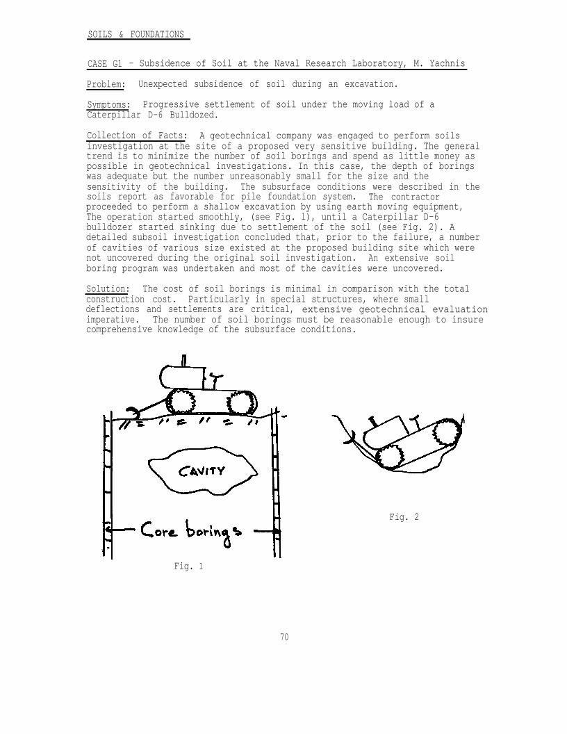
SOILS & FOUNDATIONS
CASE G1 - Subsidence of Soil at the Naval Research Laboratory, M. Yachnis
Problem: Unexpected subsidence of soil during an excavation.
Symptoms: Progressive settlement of soil under the moving load of aCaterpillar D-6 Bulldozed.
Collection of Facts: A geotechnical company was engaged to perform soilsinvestigation at the site of a proposed very sensitive building. The generaltrend is to minimize the number of soil borings and spend as little money aspossible in geotechnical investigations. In this case, the depth of boringswas adequate but the number unreasonably small for the size and thesensitivity of the building. The subsurface conditions were described in thesoils report as favorable for pile foundation system. The contractorproceeded to perform a shallow excavation by using earth moving equipment,The operation started smoothly, (see Fig. l), until a Caterpillar D-6bulldozer started sinking due to settlement of the soil (see Fig. 2). Adetailed subsoil investigation concluded that, prior to the failure, a numberof cavities of various size existed at the proposed building site which werenot uncovered during the original soil investigation. An extensive soilboring program was undertaken and most of the cavities were uncovered.
Solution: The cost of soil borings is minimal in comparison with the totalconstruction cost. Particularly in special structures, where smalldeflections and settlements are critical, extensive geotechnical evaluationimperative. The number of soil borings must be reasonable enough to insurecomprehensive knowledge of the subsurface conditions.
Fig. 2
Fig. 1
70
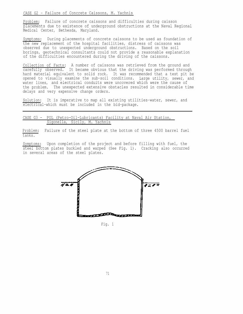
CASE G2 - Failure of Concrete Caissons, M. Yachnis
Problem: Failure of concrete caissons and difficulties during caissonplacements due to existence of underground obstructions at the Naval RegionalMedical Center, Bethesda, Maryland.
Symptoms: During placements of concrete caissons to be used as foundation ofthe new replacement of the hospital facilities, distress of caissons wasobserved due to unexpected underground obstructions. Based on the soilborings, geotechnical consultants could not provide a reasonable explanationof the difficulties encountered during the driving of the caissons.
Collection of Facts: A number of caissons was retrieved from the ground andcarefully observed. It became obvious that the driving was performed throughhard material equivalent to solid rock. It was recommended that a test pit beopened to visually examine the sub-soil conditions. Large utility, sewer, andwater lines, and electrical conduits were uncovered which were the cause ofthe problem. The unexpected extensive obstacles resulted in considerable timedelays and very expensive change orders.
Solution: It is imperative to map all existing utilities-water, sewer, andelectrical-which must be included in the bid-package.
CASE G3 - POL (Petro-Oil-Lubricants) Facility at Naval Air Station,Sigonella, Sicily, M. Yachnis
Problem: Failure of the steel plate at the bottom of three 4500 barrel fueltanks.
Symptoms: Upon completion of the project and before filling with fuel, thesteel bottom plates buckled and warped (See Fig. 1). Cracking also occurredin several areas of the steel plates.
Fig. 1
71
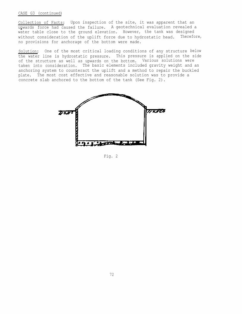
CASE G3 (continued)
Collection of Facts: Upon inspection of the site, it was apparent that anupwards force had caused the failure. A geotechnical evaluation revealed awater table close to the ground elevation. However, the tank was designedwithout consideration of the uplift force due to hydrostatic head. Therefore,no provisions for anchorage of the bottom were made.
Solution: One of the most critical loading conditions of any structure belowthe water line is hydrostatic pressure. This pressure is applied on the sideof the structure as well as upwards on the bottom. Various solutions weretaken into consideration. The basic elements included gravity weight and ananchoring system to counteract the uplift and a method to repair the buckledplate. The most cost effective and reasonable solution was to provide aconcrete slab anchored to the bottom of the tank (See Fig. 2).
Fig. 2
72
CASE G4 - A Foundation Failure in Compressible Soils, M. Jones
Problem: Inadequate foundation design and improper pile placement.
Symptoms: Differential settlement
Collection of Facts: In designing and building a structure on softcompressible soil, a number of errors were made. Some of these errors were:
1. Designing and building a 4 inch non-structural floor slab on top of 7feet of densely compacted fill overlying a deposit of soft silt andclay varying in thickness from 4 feet to 70 feet.
2. Failure to consider negative skin friction in determining requiredpile capacity.
3. Piles were permitted to bear in the compressible clay soil ratherthan being driven to underlying limestone.
As a result of these errors, large differential settlements were experiencedin the floor and in the columns. The distress was so severe that part of thestructure ultimately had to be demolished and rebuilt.
The seven feet of compacted fill on this site surcharged the compressiblesoils and induced differential settlements. Within two years, 8 inches ofdifferential settlement was observed. Although the Architect-Engineer hadspecified "Fill material shall be placed as soon as possible to consolidatethe subsoil---", the plans did not call for an engineered surcharge withsettlement plates and a formal monitoring program. Settlement resulting fromthe fill also induced a negative skin friction on the piles which exceeded thespecified pile capacity.
The plans required eight piles to be test driven with capacities calculated bypile driving formula. Six piles failed to meet the required drivingresistance; thus additional length of pile and pile splicing packages had tobe ordered. The A/E permitted the 65 foot long piles which were on site to bedriven full length while awaiting delivery of the additional piles andsplicing kits. Upon resumption of driving, two to three weeks later, thepiles could not be driven deeper due to a soil freeze effect. Drivingresistances were very high and consequently the A/E accepted the frozen pilesand approved the driving records.
Solution/Alternative: For this site, a structurally supported floor wasnecessary. Another alternative may have been an engineered surcharge withsand drains.
Negative skin friction on piles results from the downward movement of the soil,relative to the pile. Failure to recognize the presence of negative skinfriction can result in overloaded piles and unacceptable settlement. Methodsfor assessing this "downdrag" are given in DM 7.2. For this structure, thedowndrag loads could have been accommodated in the design, however, the A/Efailed to recognize its presence.
73

74
CASE G5 - Expansive Soils, M. Jones
Problem: Expansive clay subgrades.
Symptoms: Heaved floor slabs.
Collection of Facts: Expansive clay soils, if not properly controlled, canswell and cause significant damage to structures. In one project, which was"over the money", the lime stabilization of the subgrade was deleted as a costreducing measure. The decision was made without review of the geotechnicalengineering study. Soon after construction, after an extended rainfall, floorslabs heaved and were substantially damaged. The cost of repair was manytimes the amount saved by deleting the lime stabilization.
Solution/Alternative: Identify expansive characteristics with AtterburgLimits, soil activity, and consolidometer tests during the geotechnicalinvestigation. For limited areas such as directly under building slabs andshallow foundations, the most effective control is through removal and throughreplacement of the expansive soil with compacted granular fill. The depth ofremoval can be determined by plotting a profile of the percent expansionagainst depth (see DM 7.1). For areas of wide extent, such as highway andairfield pavements, lime stabilization is the preferred method of treatment.The tendency to swell can also be partially controlled by increasing the soilmoisture to near saturation and reducing the compactive effort.
CASE G6 - Sheetpiling/Bulkhead Replacement, A. H. Wu
Problem: Sheetpile bulkheads are extensively used in the Navy's shorelineenvironment. Many bulkheads have markedly deteriorated. Some of them arebeyond repair, while in other cases, the deterioration has been more moderate.
When a bulkhead shows extensive corrosion and deterioration, remedial workis required. Repair could be accomplished by either welding steel plates tothe corroded sheetpiles, or covering them with cast-in-place concrete panels.However, installing a new sheetpile in front of the existing one, and joiningthe two by a tie-rod, is probably more cost effective. This bulkheadreplacement method can be employed if the existing bulkhead has moderatedeterioration, and the structure is in stable condition.
In the NAVFAC DM-7.2 [2], Chapter 3, Analysis of Walls and RetainingStructures, a free-earth support method is described. Fig. 1 shows thefree-earth support method adopted by the Navy.
Until now, the free-earth support method has been generally used inbulkhead replacement design. However, there are some difficulties with thisapproach: (a) it commonly assumes that the existing bulkhead has neitherusable value nor supporting capacity even though the structure is to remainin-place, (b) values of the soil strength parameters are conservativelyassumed, with the common result of an overdesign calling for excessivesheetpile length, unnecessarily large steel section modules, and an anchorspacing closer than necessary. If the soil is a weak soil, replacement ofbulkhead by the free-earth method is impractical and uneconomical.
75
Symptoms: Corrosion, deterioration, subsidence and failure of bulkhead.
Collection of Facts: To determine the extent of bulkhead deterioration, fieldinspections were conducted by the Navy at many Naval Stations. Some importantfindings were:
(1) Corrosion of sheetpiling occurred mainly in the low tide range,between El. 0.0 to -3.O ft.
(2) Evidence of deterioration was seen on the side faces and webs ofthe Z-sections, where honeycomb type cavities and large holeshad developed. In most cases, there was a clear and consistentpattern. A band of heavy corrosion appeared in the low tiderange, from below the mean low water line to 3 ft below.
(3) Below the low tide range and down to the mud line, corrosionappeared to be relatively light. Corrosion in the upper tiderange and splash zone was moderate.
(4) Anchor-rod and wales generally showed very little corrosion.
Fig. 2 shows the condition of an anchored bulkhead after 25 years inservice. Fig. 3 shows the corrosion on a sheetpile 28 years of age. As aresult of the field inspection findings, the Navy has designed and constructedreplacement bulkheads by driving a new sheetpile in front of the old sheetpileand connecting the two by a tie-rod. This design method was used recently atthe U. S. Naval Station, Annapolis, Maryland. In 1942, a bulkhead was built,consisting of 232 section sheetpiling, double channel wales, steel tie-rod,and timber pile anchorage. In 1976, it was found that deterioration hadoccurred in the intervening 34 years. The damaged bulkhead was replaced byinstallation of new 227 sheetpiles in front of the old sheetpiles. Fig. 4shows the actual bulkhead replacement.
Solution: Rather than replace corroded sheetpiles, it may be more economicalto drive new sheetpiles a short distance, say, 3 to 4 ft, in front of theexisting sheetpiles. To calculate the supporting effect of the old sheetpile,the method of stability analysis can be modified. Fig. 5 shows a scheme ofthe bulkhead replacement. The modified stability analysis and designprocedures are presented as follows:
(1) Calculate the active earth pressure, Pa, to a depth of Dmin
which is about 20% shorter than the depth D.
(2) Assume 60% of the anchor-rod's yield strength will be availableto resist an overturning force, or use the anchor rod pull forcecalculated from the free-earth support method. If earthquakeinduced dynamic loading is to be included in the design, then75% of the anchor-rod yield strength may be used.
(3) Calculate the weight of backfill, W, placed between the new andexisting sheetpiles.
(4) Calculate the passive earth pressure, Pp, from the assumedpenetration depth D' which is equal to Dm i n.
76
(5) Use Equation (1) to determine the stability against overturningabout Point B. If the factor of safety is less than 1.50,increase the depth D'. The stability safety factor can be alsoincreased by increasing the new sheetpile distance d.
(6) Use the same type of sheetpile and the same size of anchor-rodfor the new structures.
(7) Connect the top of the existing sheetpile to the new concretedeck.
The following steps are recommended to assure a proper design.
(1) Take enough soil borings to accurately estimate the subsoilconditions. Preferably, the spacing of the soil borings along thebulkhead line should nut exceed 50ft.
(2) Perform soil laboratory tests on undisturbed soil samples to determineshear strength parameters accurately, as they are essential to thebulkhead design. Consolidated undrained triaxial shear tests arerecommended, if there is no dredging.
(3) Inspect the existing structures, i. e. sheetpiles, wales, tie-rods,and anchorage system by diver and by excavation of test pits to verifythat the supporting capacity of the existing structures can beincluded in the design. The validity of this depends on an accurateassessment in this regard.
(4) Check earthquake loading requirements. If the bulkhead is animportant structure and the earthquake induced loading is critical tothe bulkhead, the earthquake load should be included. One approachfor this case is to use the total stresses, in lieu of the effectivestresses, to compute the active earth pressure against the sheetpile.In this dynamic loading case, the anchor-rod working stress may beincreased to 75% of the yield strength and the required safety factoragainst overturning may be assumed somewhere between 1.3 and 1.2.
COMMENTS:
If an anchored bulkhead has corroded after many years of service, but isstructurally stable and field inspection revealed that the anchorage system isin good condition, then a cost effective replacement method may be adoptedusing the above method. The new sheetpile need not be installed deeper thanthe existing sheetpile unless dredging in front of the new wall is needed.
77
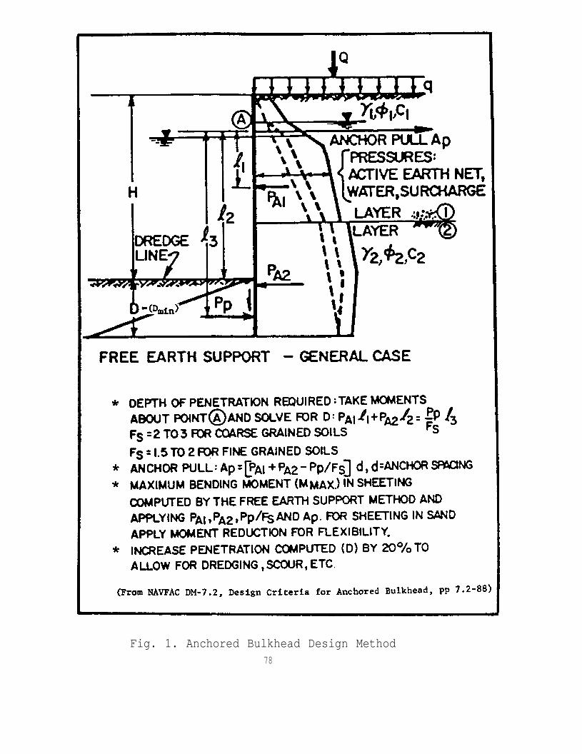
Fig. 1. Anchored Bulkhead Design Method78
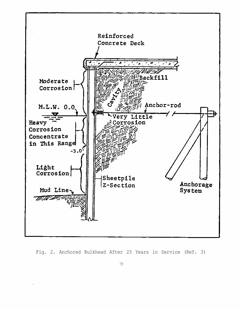
Fig. 2. Anchored Bulkhead After 25 Years in Service (Ref. 3)
79
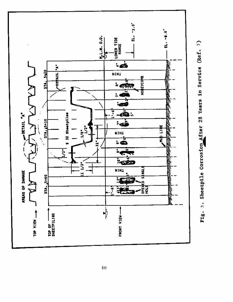
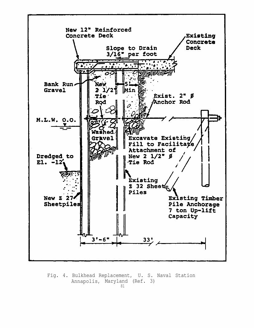
Fig. 4. Bulkhead Replacement, U. S. Naval StationAnnapolis, Maryland (Ref. 3)
81
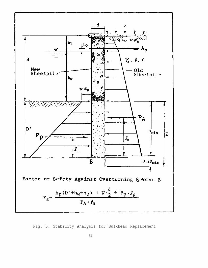
Fig. 5. Stability Analysis for Bulkhead Replacement
82
CASE G7 - Lateral Earth Pressure and Structural Adequacy of Drydock Wall, A. H. Wu
Problem: Determination of earth pressure and the structural adequacy of the wallsof an existing drydock (Mare Island Naval Shipyard, Drydock No. 3)
Symptoms: Elementary analysis indicating structural inadequacy.
Collection of Facts:
1. The methodology for determining dynamic loading acting on a massive drydockwall, which retains submerged backfill, has not been well established or verified.
2. Previous analyses did not consider the following which affect the stabilityof the wall against lateral pressure:
a. Two rows of closely spaced timber piles support the outer crane railsurrounding the dock. The configuration of these piles should attenuate the effectof the postulated seismic induced dynamic earth pressure.
b. The rail support beam of the outer rail is tied to the top of the wallby a series of struts. The rail support beam, pile caps, struts and pilesconstitute a system which will restrain the top of the wall and resist lateralmovement and overturning.
c. Total liquefaction of the soil behind the walls is not likely to occurand therefore, it should not control the analysis of the structure.
d. It is reasonable to assume tension potential in concrete, when aseismic safety evaluation against a postulated risk of an existing concretestructure is made.
Solution:
1. Take concrete core samples at the critical plane to determine the tensileand compressive strength of concrete.$15k)
(Approximate cost of sampling and testing is
2. Conduct field check to determine if reinforcing steel exists around theflooding tunnel by using a pachometer (reinforcing steel locator).
3. Install two strong-motion accelographs;a free field location in the Navy Yard.
one on the drydock and the other at
is $6k)(Approximate cost of installation by NCEL
4. Perform periodic surveys of wall movement and rotation during the dockflooding and dewatering cycles. (May use tiltmeter)
5. Annually and after each earthquake of magnitude five or greater on theRichter Scale, record cracks, if any, in the wall and floor of the drydock,pumphouse and tunnels equal to or greater then l/8 inch in width.
The above methodology was implemented and it was verified that the drydock wallwas structurally adequate.
83
CASE G8 - Pile Driving Problems, A. H. Wu
Problem: Difficulty in driving piles as required by the specification.
Symptoms: The following difficulties were encountered during installation ofcast-in-place pipe pile at Physical Education Center, U.S. Naval Academy.
1. Pile damage resulting from overdriving.
2. Piles cannot be driven to anticipated depth.
3. Piles do not achieve anticipated resistance.
Collection of Facts:
1. The pile driving criteria was excessive and resulted in overdriving ofthe piles. Consequently, damage occurred in some piles.
2. There were three pile load tests available for this project. However,the load test results and the associated pile driving records were not fullyused to develop the driving criteria. The existing criteria relied heavily onvery high dynamic blow counts. This tends to overstress the shell pile duringdeep driving which causes pile deformations and driving difficulties.
3. The pile driving criteria, even though it is excessive, wasestablished for a pile to carry 60 ton allowable bearing capacity. However,it appears that only a few of the piles are requiring 60 ton bearing capacity(many of them require between 40 to 50 ton capacities. Tension piles in thepool areas to resist uplift force are believed to need lesser capacity). Itis incorrect to use a 60 ton pile driving criteria to control all the pileinstallation when many of the piles do not require 60 ton capacity.
Causes:
1. Excessive pile driving criteria.
2. Unusual and/or inhomogeneous site conditions.
3. Improper test pile program and interpretation of test results.
Solution: It is important to correct the pile driving criteria so thatoverdriving can be avoided and pile damage can be eliminated. This, ofcourse, will result in a government cost saving. In this regard, it issuggested that:
a. Driving criteria should be adjusted to accommodate actual bearingcapacity needed. Namely, different driving criteria for 40, 50, and 60 tonpiles can be used.
b. For 60 ton pile capacity,read that:
the driving criteria should be modified to"Piles shall be driven to a depth where the dynamic blow counts
shall be greater than 10 blows per foot for at least 20 feet."
84

CASE G9 - Landfill Stabilization, Naval Academy, A. H. Wu
Problem: The U.S. Naval Academy is engaged in modernization and expansion ofits educational facilities which included construction of the multimilliondollar Nimitz Library and Rickover Hall. To Support the Nimitz Library, alandfill of about 3.5 acres was constructed along the Dorsey Creek in 1970.The Nimitz Library is founded on cast-in-place concrete pipe piles which arepartially embedded in the landfill.
Before the filling, the elevation of the area ranged from -3 to -20 ft.Soil borings showed a deep layer of soft organic clay averaging about 55 ftthick underlying the fill site. Analysis indicated that this clay soil, whichhas low shear strength and high compressibility characteristics, would notsafely sustain the weight of ordinary fill necessary to raise the grade toabout +5 ft. The measured shear strength of the clay was 150 to 350 psf.
To complete the expansion on schedule, the landfill material used waslightweight oyster shell to lessen instability of the embankment and to reducesettlement. Vertical sand drains were then installed to accelerateconsolidation of the underlying clay material. The landfill was completed inSeptember 1971.
Symptoms: The fill surface showed large and rapid subsidence. The rate ofsubsidence was far greater than the settlement anticipated from consolidationof the soft clay soil. A careful inspection of the Nimitz Library structurerevealed cracks in some of the pile caps and girders.
Collection of Facts: Subsequent investigation of the problem revealed thatexcessive fill movements were aggravated by overloading of the upland areaduring construction of Nimitz Library and Rickover Hall. The lateral movementappeared to have caused additional earth pressure to the piles embedded in thefill area, thus creating a potential for structural damage to the librarybuilding. The large settlement which occurred in the landfill made the areaunusable. Fig. 1 shows the potential of instability with existing siteconditions.
As an emergency solution, about 2 to 3 ft of upland fill was removed inMarch 1974 to prevent general slide of the landfill embankment. After removalof the fill, the vertical settlement declined from about 1.25 inches a monthto 0.25 inches a month, while the maximum lateral displacement slowed fromabout 0.30 inch/month to 0.10 inch/month. The rate of movement, however,remained the same through 1975.
Lowering the fill grade resulted in the area being flooded whenever a hightide in the creek occurred, and vehicle access was lost. However, withoutfirst improving the stability of the entire landfill, it could not be restoredto its original level.
Solution: In February, 1977, remedial work to stabilize the landfillstarted. The stabilization method included application of several techniques:
1. A counterweight was applied at the tow of the fill slope and the slopewas flattened to confine the entire fill area. A stone berm was constructed
86
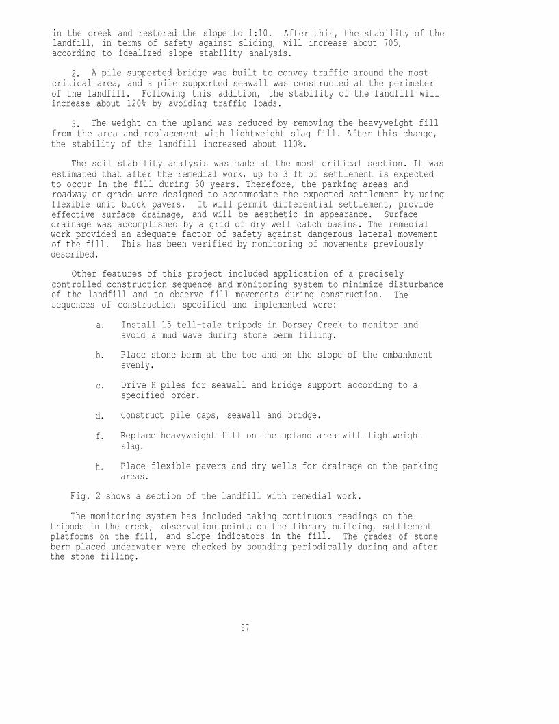
in the creek and restored the slope to l:10. After this, the stability of thelandfill, in terms of safety against sliding, will increase about 705,according to idealized slope stability analysis.
2. A pile supported bridge was built to convey traffic around the mostcritical area, and a pile supported seawall was constructed at the perimeterof the landfill. Following this addition, the stability of the landfill willincrease about 120% by avoiding traffic loads.
3. The weight on the upland was reduced by removing the heavyweight fillfrom the area and replacement with lightweight slag fill. After this change,the stability of the landfill increased about 110%.
The soil stability analysis was made at the most critical section. It wasestimated that after the remedial work, up to 3 ft of settlement is expectedto occur in the fill during 30 years. Therefore, the parking areas androadway on grade were designed to accommodate the expected settlement by usingflexible unit block pavers. It will permit differential settlement, provideeffective surface drainage, and will be aesthetic in appearance. Surfacedrainage was accomplished by a grid of dry well catch basins. The remedialwork provided an adequate factor of safety against dangerous lateral movementof the fill. This has been verified by monitoring of movements previouslydescribed.
Other features of this project included application of a preciselycontrolled construction sequence and monitoring system to minimize disturbanceof the landfill and to observe fill movements during construction. Thesequences of construction specified and implemented were:
a. Install 15 tell-tale tripods in Dorsey Creek to monitor andavoid a mud wave during stone berm filling.
b. Place stone berm at the toe and on the slope of the embankment
c.
d.
f.
h.
evenly.
Drive H piles for seawall and bridge support according to aspecified order.
Construct pile caps, seawall and bridge.
Replace heavyweight fill on the upland area with lightweightslag.
Place flexible pavers and dry wells for drainage on the parkingareas.
Fig. 2 shows a section of the landfill with remedial work.
The monitoring system has included taking continuous readings on thetripods in the creek, observation points on the library building, settlementplatforms on the fill, and slope indicators in the fill. The grades of stoneberm placed underwater were checked by sounding periodically during and afterthe stone filling.
87

The main landfill stabilization work was essentially complete in March1977. The stabilization method used in this project has, so far, provensuccessful. The progressive lateral movement of the fill toward the creek hasbeen arrested. The danger of such movement, which occurred particularly tothe library building, has been eliminated. The landfill area has beenrestored as a fire vehicle access route and as an aesthetically pleasant siteconforming to the surroundings of the Naval Academy environment.
88
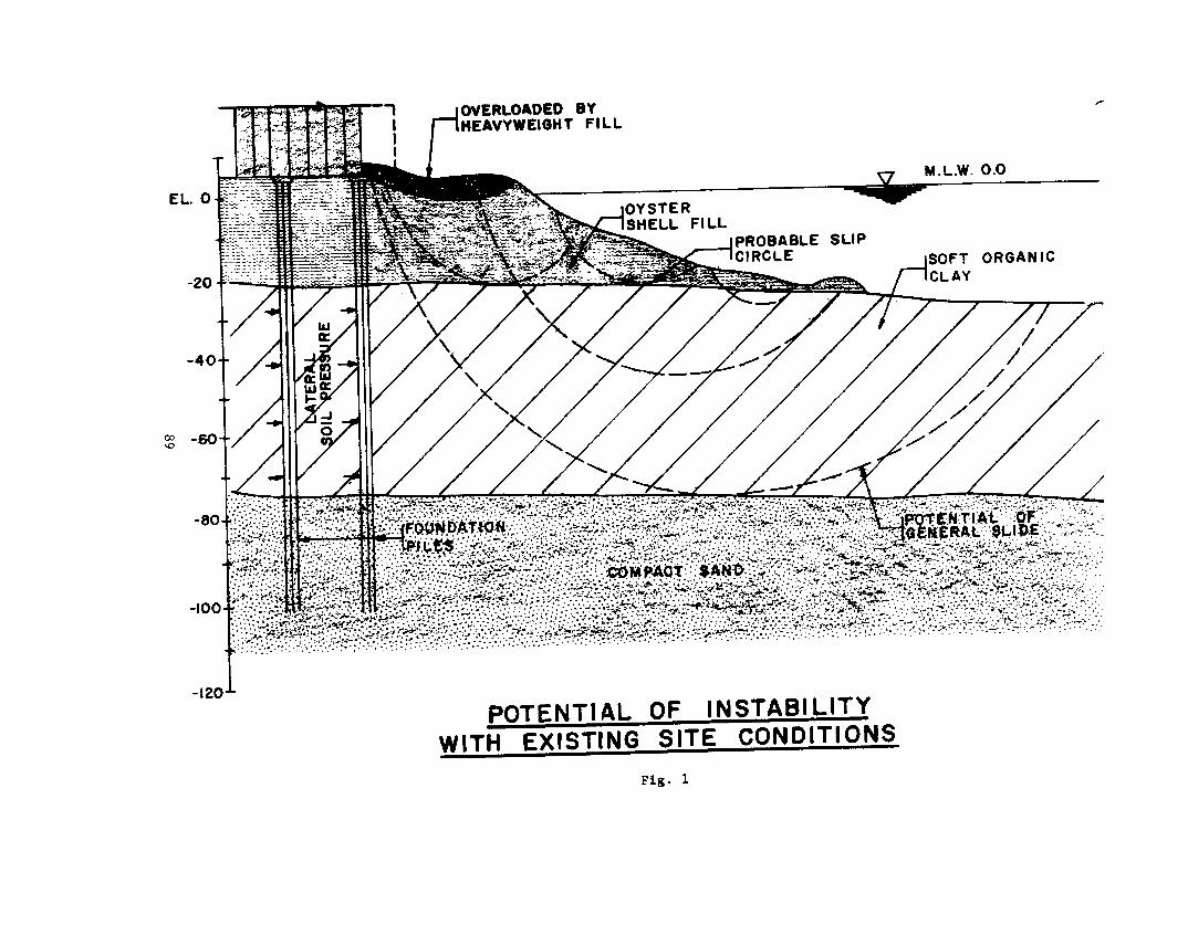
CASE G10 - Foundation on Compacted Fill, A. H. Wu
Problem: Economic design of foundation for buildings located at the AnacostiaNaval Station.
Background: In 1976, a $2.2 million automotive maintenance facility wasconstructed on a compacted structural fill placed over a very thickcompressible clay layer. The facility, designed by the Naval FacilitiesEngineering Command, is located east of where the Anacostia River meets thePotomac River.
A large land area has been reclaimed here since 1884. The subsoil conditionsof this filled land consist of deep deposits of soft silty clay extendingtypically to a depth of 60 ft. Because of the weak soil conditions, pilefoundations had been used exclusively to support structures built in the fillareas in the past.
Use of conventional pile foundations at the new facility would have been verycostly. Furthermore, they would have resulted in the recurring operationaland maintenance problems associated with the differential settlement betweenthe pile-supported buildings and the adjacent fill supported side-walks,driveways, and landscaping.
The project consisted of three separate one-story buildings. The maximum wallload was 5 kips per linear foot, and the maximum bearing wall span is about140 ft. Since the project site is located in a flood plain area, the masterplan required the building sites to have a finish grade at about 6 ft abovethe original surface, which was at about elev, +4.0. Parts of the buildingareas were located over an old concrete pavement.
At first, the project faced two major foundation problems: (1) theprobability of large overall settlements along with differential settlements,and (2) the possibility of excessive foundation cost.
Symptoms: High cost of foundation.
Collection of Facts: The soil boring indicated that the site subsoilsconsisted of 4 ft of recent medium dense silty sand fill, 55 to 60 ft of softsilty clay with slight organic content, and then a dense silty sand extendingto 120 ft depth. The results of soil testing showed the silty clay materialto have been normally consolidated and to have high compressibilitycharacteristics.
Consolidation test results were used to predict the rate and magnitude of thesettlement which would occur from the weight of the fill required to raise thegrade. Computer settlement analyses indicated that the ultimate settlementresulting from the fill load alone was approximately equal to 33% of theheight of the fill placed. In other words, to raise the grade 6 ft, about 9ft of fill would be necessary (allowing up to 3 ft of settlement). The rateof consolidation would be so slow that preloading the site with surcharge toaccelerate the consolidation settlement would not have been an effectivesolution.
91
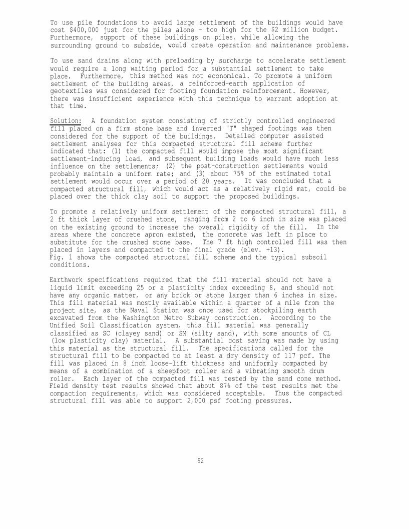
To use pile foundations to avoid large settlement of the buildings would havecost $400,000 just for the piles alone - too high for the $2 million budget.Furthermore, support of these buildings on piles, while allowing thesurrounding ground to subside, would create operation and maintenance problems.
To use sand drains along with preloading by surcharge to accelerate settlementwould require a long waiting period for a substantial settlement to takeplace. Furthermore, this method was not economical. To promote a uniformsettlement of the building areas, a reinforced-earth application ofgeotextiles was considered for footing foundation reinforcement. However,there was insufficient experience with this technique to warrant adoption atthat time.
Solution: A foundation system consisting of strictly controlled engineeredfill placed on a firm stone base and inverted "T" shaped footings was thenconsidered for the support of the buildings. Detailed computer assistedsettlement analyses for this compacted structural fill scheme furtherindicated that: (1) the compacted fill would impose the most significantsettlement-inducing load, and subsequent building loads would have much lessinfluence on the settlements; (2) the post-construction settlements wouldprobably maintain a uniform rate; and (3) about 75% of the estimated totalsettlement would occur over a period of 20 years. It was concluded that acompacted structural fill, which would act as a relatively rigid mat, could beplaced over the thick clay soil to support the proposed buildings.
To promote a relatively uniform settlement of the compacted structural fill, a2 ft thick layer of crushed stone, ranging from 2 to 6 inch in size was placedon the existing ground to increase the overall rigidity of the fill. In theareas where the concrete apron existed, the concrete was left in place tosubstitute for the crushed stone base. The 7 ft high controlled fill was thenplaced in layers and compacted to the final grade (elev. +13).Fig. 1 shows the compacted structural fill scheme and the typical subsoilconditions.
Earthwork specifications required that the fill material should not have aliquid limit exceeding 25 or a plasticity index exceeding 8, and should nothave any organic matter, or any brick or stone larger than 6 inches in size.This fill material was mostly available within a quarter of a mile from theproject site, as the Naval Station was once used for stockpiling earthexcavated from the Washington Metro Subway construction. According to theUnified Soil Classification system, this fill material was generallyclassified as SC (clayey sand) or SM (silty sand), with some amounts of CL(low plasticity clay) material. A substantial cost saving was made by usingthis material as the structural fill. The specifications called for thestructural fill to be compacted to at least a dry density of 117 pcf. Thefill was placed in 8 inch loose-lift thickness and uniformly compacted bymeans of a combination of a sheepfoot roller and a vibrating smooth drumroller. Each layer of the compacted fill was tested by the sand cone method.Field density test results showed that about 87% of the test results met thecompaction requirements, which was considered acceptable. Thus the compactedstructural fill was able to support 2,000 psf footing pressures.
92

The footings were designed as inverted "T" shaped grade beams. These inverted"T" shaped footings were sized and reinforced to provide the strength requiredto carry the superstructure. The structural system for the superstructure isload-bearing masonry walls and open-web joists for the partial second floorand the roof. This structural system was selected as the most economical inlight of the aesthetic constraints on the exterior finishes imposed by thefacility master plan.
The masonry walls are not flexible in terms of accommodating differentialsettlements. The wall footings, however, were designed to be rigid enough tobridge over or otherwise resist differential settlements in the event that thefooting lost support for a span of 10 ft such as at a building corner.Considering the potential footing subgrade problems, the inverted "T" beamfooting size and reinforcing were selected so as to provide the strength andeffective moments of inertia required to resist footing deflections. Thisdesign limits the differential settlements experienced by the masonry walls toa tolerable range. The floor slab was reinforced both in the top and in thebottom of the slab. It was cast directly on the surface of the compactedfill, and was set on and tied to the inverted "T" shaped grade beams at theedges. This was done to ensure that the floor slab would continue to settleat the same rate as the building walls, and to prevent the slab from remainingsomewhat buoyant while the building footings and superstructure settled.
To control the quality of the compacted fill work and to monitor theconsolidation of the soft, silty clay stratum, 15 settlement plates wereinstalled on the existing ground surface to monitor the settlements during thecompacted structural fill work. The settlement plates were observed weeklythroughout the two-month compacted fill placement, and monthly during the18-month facility construction period. After construction, settlementreadings were made at a lesser frequency ranging from three months to yearlyby March 1981. Observations were made by reading elevations on steel platesand pipes placed on original grade.
Four pneumatic piezometers, consisting of wellpoint and pore water pressuresensing elements, were installed after completion of the compacted structuralfill to evaluate the pore water pressures developed in the clay material fromthe fill and building loads. The piezometer readings showed that the porewater pressures dissipated slowly, and were leveling off at a rate which wasconsistent with the rate of settlement. They provided a good correlationbetween the actual and predicted rate of settlement.
The construction of this project began in August 1976. The average settlementwhich had occurred by the completion of the compacted fill work was about 2inches. Construction of the building was completed in June 1978. The averagerate settlement measured after completion of the buildings was about 3 inchesper year, about 16% higher than predicted by analytical results. From thebeginning of the project to March 1981, the average and maximum settlementswere about 1.3 and 1.5 ft respectively. No wall cracks or structural distressof the buildings have occurred to this date.
Designing structural foundations to accommodate the effects of largesettlements is a real challenge to engineers. The risk of foundation failureor building damage can be minimized if the foundation system is designed insuch a way that it can promote a uniform settlement over the building area.
93

94
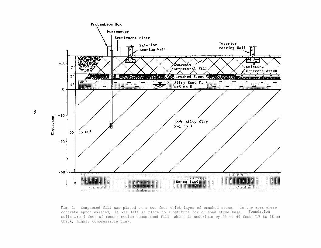
Fig. 1. Compacted fill was placed on a two feet thick layer of crushed stone. In the area whereconcrete apron existed, it was left in place to substitute for crushed stone base. Foundationsoils are 4 feet of recent medium dense sand fill, which is under1ain by 55 to 60 feet (17 to 18 m)thick, highly compressible clay.

CASE G11 - Failure of Timber Pile Foundation, NRL, M. Yachnis, & J. V. Tyrrell
Problem: Distress in structure, failure of timber pile foundation at Bldg. 43,Naval Research Laboratory.
Symptoms: Gradually diagonal shear cracks and tension cracks developed inreinforced concrete beams and horizontal tension cracks in columns. Differentialsettlement became evident.
Collection of Facts: Observation of the cracks indicated that the cracks on thebeams were generated by reversal of stress - Fig. 1. The cracks in columns werecaused by lack of pile support which resulted in the adjacent framing supportingthe column instead of the column supporting the structure with the lower column andpile caps creating a tension load - Fig. 2.
Exploratory pits were opened to check the timber piles and concrete pile caps. Thetimber piles under the structural members which had experienced cracks were founddeteriorated and in some cases the upper portion was completely decayed. After anextensive exploration at various locations of the piles, the problem area wasisolated. A large diameter sewer pipe runs along the deteriorated piles. Theleakage from and infiltration to the pipe was the apparent cause of thedeterioration.
Fig. 1 Fig. 2
Solution: Possible causes of reinforced concrete beam and column cracking areoverloading, underdesign, material deterioration and poor quality of materials. Inaddition, such in the above case, investigators should check for foundationsettlement, pile deterioration and failure in caps.
96

POL FACILITIES/ENERGY
CASE POL 1 - POL Storage Tanks, Spark Generating Equipment, R. Thomas
Problem: Perpetuated myths in and around full storage tanks concerning sparkgenerating equipment.
Symptom: Unnecessary costs and job delays while trying to obtain specializedequipment. Injuries from using non-ferrous tools with less strength.
Collection of Facts: The American Petroleum Institute (API) has issued 3safety documents covering the most commonly misunderstood areas concerningspark generation:
1. API-PSD2214 - So called "non-sparking" (non-ferrous) tools offer nomore degree of safety over ordinary ferrous tools.
2. API-PSD2213 - Subscriber type (Bell) telephone systems cannotgenerate enough power for fuel ignition and therefore are suitablefor Class 1, Group D atmospheres.
3. API-PSD2212 - Flashlights containing 3-cells and less cannot generateenough power for ignition and therefore do not need to be explosionproof.
Solution: The API safety documents are endorsed by NAVFAC and can bereferenced along with NAVFAC MO-230 when performing maintenance around fuelfacilities.
CASE POL 2 - Thermal Expansion of Fuel, R. Thomas
Problem: Excessive pressures from thermal expansion of fuel downstream ofpressure control valve even though system contains a pressure relief valve(PRV).
Symptom: Bulging or bursting of pantograph fueling hose and leaking swivels.
Collection of Facts: When an angle pattern PRV is used to relieve thermalpressure buildup from downstream to upstream around a block valve, the springrelief setting on the valve can be misleading if the upstream piping remainsunder pressure. The actual relief pressure becomes the value of the springplus the upstream pressure which is also acting on top of the valve. Forexample, if the PRV has a 150 psi spring setting and the upstream pressureholds at 170 psi, relief will not occur until 150 + 170 = 320 psi is obtained,which may damage the hose.
Solution: Either relieve to an unpressurized line (return line) with the PRV,or incorporate a thermal relief check valve around the shut-off valve torelieve upstream. In stainless steel, the relief valve runs about $400 whilethe thermal relief check is about $50.
97
CASE POL 3 - Tires for Refueling Vehicles/ FOD Hazard, R. Thomas
Problem: Stones being picked up in the tire treads of aircraft refuelertrucks and dropped on the aircraft parking apron, creating a F.O.D. (ForeignObject Debris) hazard.
Symptom: Engine damage to aircraft and G.S.E. (Ground Support Equipment)turbine engines due to F.O.D. pickup by air intake.
Collection of Facts: Due to the location of many Navy refueler fill stands,and the roads traveled by refuelers, stones are picked up in the truck tiretreads. When anti-F.O.D. tires are used, tread life is short, and there isstill some stone pickup which must be removed.
Solution: Field tests have been initiated and completed at NATC PatuxentRiver using "racing slick" type recap tires on refuelers. They carry noF.O.D. and results show about l/3 more tire life than threaded tires.Traction has proven to be excellent in all types of weather-rain, ice andsnow. Stations and contract refuelers now have the option to go to "slick"tires and feed-back from the field is showing similar good results.Commercially, Dulles Airport is now using "slick" tires on their "peoplemovers" to transfer passengers from the terminal to the aircraft out on theflight line.
CASE POL 4 - Failure of Filter/ Separators, R. Thomas
Problem: Failure of filter/separators (F/S) to coalesce water at aviationrefueler fill stands.
Symptom: Premature shut-down of fuel flow by fuel contamination monitorsduring water overload.
Collection of Facts: During recent fuel facility surveys at Navy and Marineair stations, it was noted that when stations converted from top loading tobottom loading fill stands, lubricated swivels and valves were reused. Due totheir age, some had leaks and a way to stop the leak was to pump grease intothe fitting. Unfortunately, some grease works its way into the fuel and ineffect "wets" the coalescencers and prevents the "beading" or "coalescing" ofwater droplets. With a faulty or slow acting slug, valve water can then passthrough the F/S and cause premature shutdown of fuel monitors at the fillstand or on the refueler trucks.
Solution: Replace all lubricated valves and swivels at aviation refueler fillstands with non-lubricated type. (As required by NAVFAC DM-22).
98
CASE POL 5 - Pressure Relief Valve (PRV), R. Thomas
Problem: Difficulty in determining whether a Pressure Relief Valve (PRV) isopening or is stuck in the open position when relief piping is hard connectedinto remote waste tank.
Symptom: Premature filling of waste fuel holding tank with good fuel.
Collection of Facts: Frequently Filter Separator (F/S) water discharge pipingand PRV piping from F/S and distribution piping is hard piped into a wasteholding tank. When waste tank starts filling with fuel prematurely, itbecomes almost impossible to determine where the fuel is coming from.
Solution: Install sight glass fittings with visual paddle wheel in all PRVdischarge piping that goes to a holding tank. Spinning paddle can be used tolocate leaking PRV or to adjust spring compression on PRV so that dischargerelief pressure is set correctly.
CASE POL 6 - Spring Loaded Check Valve, R. Thomas
Problem: Use of spring loaded check valve as a deadman control valve at truckfill stands when converting from top loading to bottom loading.
Symptom: High surge pressure when spring valve is released and duringfueling, overfilled trucks due to "tying open" of loading valve during fillingoperations.
Collection of Facts: In a top loading configuration, a spring loaded checkvalve with a pull chain attached was used as the main fuel loading valve.When many top loading fill stands were converted to bottom loading, the springloaded check valve was reused as a deadman valve. Because of itsconfiguration and ease to wire open, several truck overfills have resulted.
Solution: Replace spring loaded check with hand held electronic type deadmanand incorporate "Scully" or similar high level shut-off system.
CASE POL 7 - Latex Lining System for Concrete fuel storage tanks, R. Thomas
Problem: NFGS 09871, latex lining system for concrete fuel storage tanks,requires the latex blend to be used within 45 days of manufacture. For mostcontracts, this time limitation is too restrictive.
Symptom: Rejection by ROICC of latex paint because its age exceeds 45 days,causing contract delays and reordering problems.
Collection of Facts: The Naval Research Lab has shown that paint as much as 1year old can still perform good as new if it has been stored at temperaturesnot less than 40°F nor more than 110°F and that it still has a smooth,paint like consistency.
Solution: Examine the paint for consistency and smoothness rather than dateof manufacture. A revision to the specification will be recommended.
99
5 psi at the skin of the aircraft. Flow rate into an aircraft is governed b ythe internal plumbing restrictions and the number of empty tanks fuel isflowing into. The rate which fuel is accepted by an aircraft varies fromstart to finish, with highest flows occurring initially and a steady declinein fueling rate to zero as the aircraft fills up.
Solution: Design aircraft direct fueling station to provide pressure controland let the aircraft control the rate at which it will accept fuel. This ratewill vary from aircraft to aircraft and fueling will be accomplished as fastas possible for each aircraft.
CASE POL 10 - Pressure Control at Direct Fueling Stations, R. Thomas
Problem: Over pressurizing aircraft fuel tanks.
Symptom: Ruptured aircraft fuel tanks.
Collection of Facts: As configured, several Navy and Marine Corps aircraftdirect fueling stations cannot limit the pressure at the fueling nozzle to therequired 50±5 psi. The provision of a hose-end pressure regulator is only aback-up or secondary device for limiting the pressure to aircraft. Theprimary pressure control should come from the hydrant fuel control valve.
However, without a venturi, this valve must be set for 50 psi so as not tooverpressure the aircraft at no flow conditions. This means that when fuel isflowing, the nozzle pressure may be down to 25 psi or less reducing the flow.If the pressure control valve is set up to 75 psi to compensate for the dropduring flow conditions, the plane will see 75 psi at no flow conditions. Thisis a dangerous situation.
Solution: Install a hose end regulator for secondary protection and provide aventuri controller for the hydrant fuel control valve so that it becomes theprimary pressure control valve. With a venturi, both conditions will besatisfied--the aircraft will be protected at no flow conditions, and thecontrol valve will be "tricked" into opening wide during maximum flowconditions.
CASE POL 11 - Pantograph Stops, R. Thomas
Problem: Most existing pantograph stops are made from steel posts with rubberpads. The problem with this is that when pantographs are folded shut, theswivels can clash together, causing damage and leaks.
Collection of Facts: Definitive drawings call for padded posts as pantographstops. Field surveys revealed that even with pads on pantograph piping, theimpact of a folding pantograph causes damage to the swivels.
Solution: A simple yet effective means to prevent pantograph clash and swiveldamage was observed at several MCAS's. The idea is to provide stops for thecastors before the piping and swivels have a chance to contact each other.Castor stops are shown below and can be provided for as many castors asrequired.
CASE POL 12 - Static Electricity Relaxation at Direct Fueling Stations,R. Thomas
Problem: Providing static electricity relaxation capability at existingaircraft direct fueling stations while keeping below the 3 foot heightlimitations.
Symptom: Most static relaxation tanks are of the vertical type, and when usedat aircraft direct fueling stations, can cause wing tip damage to aircraft.
Collection of Facts: Older direct aircraft fueling systems and some newlymodified systems which have the filtration equipment near the dispensing pointare required to provide 30 seconds fuel retention time between the last pieceof filtration equipment (the fuel contamination monitor) and the refuelingnozzle. In most cases a vertical tank will violate the 3 foot heightlimitation and there is not room to install a horizontal tank.
Solution: A simple solution, observed at one air station and which saves theapproximate $4,000 cost of a non-ferrous relaxation tank, uses little spaceand provides the required low profile. It is to increase the pipe diameter upto 10" or 12" and to install a large aluminum pipe "U" bend in the pipingsystem. The "U" bend is fabricated from standard elbows or "U" bends andstraight pipe and the slower velocity (FT/SEC) times 30 seconds retention time= required length (FT).
CASE POL 13 - Corroded Fuel Tank Bottom, R. Thomas
Problem: Trying to decide whether to replace a corroded fuel tank bottom.
Symptom: 40 year and older fuel tanks with what appears to be a badlycorroded and pitted tank bottom with possible leaks.
Collection of Facts: An A/E had decided that the bottoms in several pre-WWIIfuel tanks were corroded to the point where the entire bottoms would have tobe replaced with new steel. A sight visit and ultrasonic inspection of thebottoms revealed that the bottom plates were made from l/2" steel plate and ahole saw cut indicated that all corrosion was occurring on the inside of thetank and that the underside looked like new steel. Furthermore, corrosion waslimited to certain low point areas in the tank. The new tank bottom was to bel/4" steel plate in accordance with latest standards (only l/2 as thick as 97%of the old tank floor).
Solution: Even though some parts of the floor were badly pitted (some pitswere as much as 3/l6" deep), there was still more steel left than would be ina brand new floor. All corrosion was interior, therefore, the isolated deeppits were fill welded and new plates were welded over the corroded areas andthe edges ground smooth. The entire tank was then coated, producing a tankbetter than new and at a fraction of the cost.
CASE POL 14 - MIL Specification Fueling Hose, R. Thomas
Problem: Failures with various MIL Specification fueling hoses.
Symptom: Short life, blisters, bulges, cracks and pin holes are just some ofthe problems experienced with several different MIL specification hoses.
Collection of Facts: For years, the Navy and Air Force have had difficulty inobtaining a good aircraft refueling hose, even though we were buying NIL spechoses. The problems with the MIL specs seem to be that the manufacturer isbeing told exactly how to construct his hose and, because of that he cannottake advantage of new advancements in materials and fabrication methods. Wehave now switched to referencing commercial API hose specifications. Thesespecs are performance oriented versus telling the manufacturer how toconstruct the hose. The result has been dramatic and we are now gettingbetter fueling hoses.
Solution: Reference API 1529 for aircraft refueling hose, and you will getthe performance you want without telling a manufacturer how to construct hishose.
CASE POL 15 - Petroleum Fuels/Energy, R. Thomas
Problem: Incorrect application of the shear-pin type emergency, dry breakawaycoupling on aircraft direct fueling pantograph stations.
Symptom: Ruptured aircraft fuel cells if breakaway is attempted withincorrect type of breakaway coupling in place.
102

Collection of Facts: There are two different types of emergency, drybreakaway couplings used by the Navy in fueling aircraft each with adesignated application and they are not interchangeable. The "shear pin" typebreakaway is used only on refueler trucks and requires an angle pull forbreakaway. The spring loaded detent ball type requires an axial pull forbreakaway and is used on pantographs or other swivel type dispensing systemswhich allow axial pull.
Solution: Insure that the proper type breakaway coupling fits the serviceapplication. Otherwise, there may be no protection at all.
103
MECHANICAL & HYPERBARICS
CASE M1 - Raceway Tubing for Hyperbaric Complex, T. Hayes
Problem: Thin walled stainless steel tubing used as electrical raceway inhyperbaric facility complex.
Collection of Facts: In an effort to keep carbon steel out of the hyperbaricenvironment, the contractor installed thin walled stainless steel tubing aselectrical raceway. When bends were made in the tubing, it crimped. Cablewas pulled anyway causing it to chafe. Rigid steel conduit or EMT should havebeen installed. Neither creates a hazard in a hyperbaric environment.
Solution: The stainless steel tubing was removed and replaced with rigidmetallic conduit.
CASE M2 - Submersible Pump for Fire Protection (Hyperbaric), T. Hayes
Problem: 220 volt submersible fire pump installed in bilge area of hyperbaricchamber complex.
Collection of Facts: As a solution to fire protection requirements, the bilgearea of the chamber complex was filled with water, and submersible fire pumpswere installed. This was the supply for the deluge system within thechamber. The fire pumps posed a hazard as a shock and fire hazard, andstagnant water pose a health hazard.
Solution: The deluge system should be supplied by a pressurized water tanklocated outside of the chamber.
CASE M3 - Air of Manned Chambers, T. Hayes
Problem: Large volumes of air are required for ventilating manned hyperbaricfacilities.
Collection of Facts: For standard recompression chambers, 48,502 SCF of airis required by the U.S. Diving Manual for ventilation to remove CO2 and O2
build-up when the complex is used for the most severe diving requirements.Usually this air is provided by charged high pressure air flask. These flasksthemselves are expansive, costly to maintain, and utilize valuable buildingspace. The required number of flasks could be reduced, if the CO2 and O2
build-up in the chamber could be reduced. One method to accomplish thisreduced build-up would be to pass CO2 and excess O2 directly out of thechamber through the inhalator which is provided with an overboard discharge.The Navy has recently approved use of such an inhalator which is manufacturedby Scottato.
Solution: Activities having hyperbaric facilities and wishing to reduce airflask procurement and maintenance costs should consider installing theapproved overboard discharge systems.
104
CASE M4 - Oxygen Enriched Testing of Materials, T. Hayes
Problem: Facilities for testing flamability and toxicity of a variety ofmaterials, both atmospheric conditions, and at elevated pressures.
Symptoms: Lack of testing capability
Collection of Facts: There are very few organizations which conduct aflamability test of a variety of materials in 100% oxygen or oxygen atelevated partial pressures. One such organization is NASA at their ClearLake, Texas laboratory.
Solution: If one desires a certain material to be tested in an oxygenenriched environment, he should contact NASA at (713) 483-5231. Samples ofthe material will have to be provided and the cost will be approximately$1,000 per sample.
CASE M5 - Drain Plugs for Recompression Chambers, T. Hayes
Problem: Steel drain plugs installed in diver recompression chambersfrequently corrode and become frozen in place.
Solution: Use bronze plugs instead of steel.
CASE M6 - Drywall Nails for Hyperbaric Facilities, T. Hayes
Problem: Standard length drywall nails are too long for normal installationof drywall over framing for pocket doors. The exposed nail tip will scar thedoor when it is slipped into the pocket.
Solution: Use construction adhesive on the framing instead of nails. Nailscan be used at the top and bottom plate but not on the framing for the door.
CASE M7 - By-pass for Gas Piping Systems (Hyperbaric), R. Johnston
Problem: Designers often do not plan for by-passes around regulators, dryers,filters and other components of gas piping systems.
Collection of Facts: In the review of many design drawings for hyperbaricfacilities, it has been noted that no provisions have been made by designersfor by-passes around such piping components as regulators and filters. Ifthese components should fail, there would be no way of providing breathing gasto chamber occupants.
Solution: Provide by-passes around piping components such as regulators andfilters.
105
CASE M8 - Oxygen Dump System, R. Johnston
Problem: Chamber O2 Overboard Dump Systems lacking differential pressureregulators.
Symptom: Potentially hazardous pressure differential between Bibs mask andoutside ambient.
Collection of Facts: Some early O2 dump systems were installed, inaccordance with manufacturers’ recommendations, without negative biasdifferential pressure regulators in the exhaust line. Although no failureshave been identified, a failure of the mask vacuum regulator could result in apotentially hazardous suction on the mask due to the pressure differencebetween the chamber and ambient.
Solution: Install a negative bias differential pressure regulator in all O2
overboard dump systems and set the differential to approximately 15 psig.
CASE M9 - Materials for Oxygen System, T. Hayes
Problem: Use of Buna-N as seat material for O2 valve resulted in O2 fire.
Collection of Facts: Buna-N was used as seating material in an O2 valve.When the valve was opened, the adiabetic heat of compression caused the Buna-Nto ignite resulting in an O2 fire.
Solution: Do not use Buna-N as seating material in O2 valves. Use Kel-F orteflon as valve seating material.
CASE M10 - Volume of Ventilation Air - Hyperbaric, T. Hayes
Problem: It is difficult to determine the volume of air actually being usedfor ventilation of a chamber.
Collection of Facts: The standard procedure is to try to calibrate theexhaust valve using the procedure described in the U.S. Diving Manual.
Solution: Install a flow meter in the exhaust line to determine the exactrate of ventilation.
106
CASE M11 - Selection of Filters - Breathing Air System, R. Johnston
Problem: Incorrect piping of Pall Trinity particulate filters in breathingair systems.
Symptoms: Excessive pressure drop; premature failure of filter elements.
Collection of Facts: Pall Trinity produces both coalescing type moistureSeparator (reverse Ultipor) and particulate filter (Epocel) elements. Thehousing for these elements is identical, but the direction of flow is oppositefor each.
Solution: Correct piping configuration is as follows:
Reverse Ultipor - top inlet/side outletEpocel - side inlet/top outlet
CASE M12 - Freeze-up of Dome Pressure Regulators, R. Johnston
Problem: Freeze-up of dome loaded pressure regulators at several facilities.
Symptoms: Icing up of regulators; little or no air flow to low pressure side.
Collection of Facts: At least 2 installations have experienced freeze-upproblems. In each case, moisture content of the air was high but withinacceptable limits.
Solution: a. Install 2 regulators in series to "step down" pressure intwo stages, or replace regulator with one having higherflow capacity.
b. If possible, replace orifice with one of larger diameter.
c. As a last resort, add a refrigerated air dryer to system.
CASE M13 - Manned Chambers-Pressure Problem (Door), R. Johnston
Problem: The inner doors of some chambers are equipped with dogs. Thispermits the outer lock to be pressurized higher than the inner lock.
Symptoms: If door dogs fail, inner door may swing open violently.
Collection of Facts: Chamber doors were designed only to withstand pressurefrom the inside. If subject to a greater outside pressure, i.e. from theouter lock, the dogs could fail causing the door to swing open. This couldpresent a serious personnel hazard.
Solution: Remove dogs from inner lock; in the interim, post sign on chamberto warn against pressurizing outer lock greater than inner lock.
107
CASE M14 - Air System Drying After Cleaning or Hydro-test, R. Johnston
Problem: Inadequate or time consuming drying of chamber air piping systems.
Symptom: Moisture in system which may lead to corrosion.
Collection of Facts: Various cleaning procedures have been developed whichrely on forcing dry, warm air to dry the piping system. Not only is this verytime consuming, but water may not be thoroughly removed from recesses or "deadends" of the system.
Solution: After purging system with air for approximately 4 hours, pull avacuum on the system for at least 4 hours. A vacuum of 10 inches of water(.73 inches Hg) should be sufficient to boil off any water left in the system.
CASE M15 - Location of Intake for Air Supply, R. Johnston
Problem: Improper location of compressor air intake for chamber air supplysystem.
Symptom: Carbon monoxide contamination of supply air system.
Collection of Facts: The compressor air intake and filter should ideally belocated above the roof outside of the building. In some instances, the intakehas been located at ground level in proximity to vehicle exhaust.
Solution: Extend compressor air intake and filter through the roof using alength of PVC pipe appropriately sized. Care should be taken to avoid placingthe intake near diesel exhaust stacks, toilet vents, etc.
CASE M16 - Pressurization of Chamber Fire Extinguisher, R. Johnston
Problem: Inadequate pressurization of chamber fire extinguishers.
Symptom: Ineffectual spray pattern in the event that extinguisher is operatedat depth.
Collection of Facts: While most chambers are now equipped withgas-pressurized water extinguishers, inspections have indicated that someextinguishers are charged to only 100 psig. Research has shown that a chargeof 200 psig is necessary to provide adequate flow when the chamber is at depth.
Solution: Regularly inspect chamber fire extinguisher to ensure that it ischarged to 200 psig.
108
CASE M17 - Hyperbaric Chamber BIB System, R. Johnston
Problem: Potential loss of O2 breathing capability.
Symptom: No oxygen to chamber BIB system.
Collection of Facts: Some chamber O2systems are built with a single
in-line regulator. In the event that the regulator fails, there is often nobypass or system redundancy to permit continued O2 treatment. The onlyalternative would then be to shift to a less effective Air Treatment Table.
Solution: Design O2 systems with redundant regulators and valves permittingshifting of O2 supply from one bank to another, or provide a bypass withneedle valve around the regulator.
CASE M18 - Hyperbaric Recompression Chambers, R. Johnston
Problem: Recompression chambers lacking Ground Fault Protectors.
Symptom: Fire or shock due to possibility of electrical spark in the event ofline-to-ground fault in the chamber electrical system.
Collection of Facts: Recent inspections have revealed that some chambers lackground fault protection. Chamber grounding systems may be vulnerable tomoisture or other deterioration.
Solution: Require that Ground Fault Circuit interruption be installed onchamber electrical systems.
CASE M19 - Hyperbaric Pressure Relief/Safety Valves, R. Johnston
Problem: Poor location of pressure relief/safety valves.
Symptom: Personnel injury resulting from high pressure air.
Collection of Facts: Pressure relief valves are occasionally installed withtheir discharge ports inadvertently oriented so that high pressure air may bedirected towards operating personnel.
Solution: Exercise care in installation of pressure relief valves. Ifpossible, orient discharge ports away from personnel traffic or providedeflectors to harmlessly direct air away from personnel.
109
CRANES
CASE CN1 - Floating Cranes; Free-Fall Restraint, P. Malone
Problem: Dropping a torpedo while transferring from one area to another usinga 60 ton floating crane which could have resulted in great loss of lives aswell as equipment.
Symptom: While using 60 ton floating crane to off-load torpedoes, the craneoperator lost control of the load dropping it onto a barge.
Collection of Facts: Review of the original crane's design revealed that thecrane was designed so the load could be lowered in a free fall condition. Theoperation procedures provided a method to prevent such an occurrence; however,this procedure was not always followed by crane operators. The history ofaccidents with this model crane indicated that a number of similar accidentshad also occurred.
Solution: Design and install modification that prevented the operator fromusing the free fall capability design of the floating crane.
CASE CN2 - Non-destructive Testing of Crane Hooks, P. Malone and Don Potter
Problem: The requirement for annual disassembly and nondestructiveexamination of crane hooks was questioned by end users.
Symptom: The end user (Naval Shipyards) felt that it was not a cost effectivemethod of insuring crane safety and that NAVFAC should do something to providea more cost effective method for accomplishing this requirement.
Collection of Facts: The history of crane accidents was reviewed and itindicated that the only accidents involving hook failure were due to grossover-loads. An engineering investigation project was conducted to study theeffect of crack location and fatigue on hook failure.
Solution: The results of the Engineering Investigation indicated that thecritical area for hook failure could be examined while the hook was on thecrane.
110

CASE CN3 - Safety Booms for Mobile Cranes, P. Malone
Problem: Failures of mobile crane booms.
Symptom: Mobile crane had a history of failing when an examination revealedonly minor damage that on the WW II vintage cranes presented no problems.
Collection of Facts: The review of mobile crane boom design indicates thatthe new booms were designed using high strength steel (in the 100,000 psiyield range). This high strength steel allowed the l/r ratio support to beincreased to maximum ratio. This higher l/r ratio means that if support(diagonals) is lost any where along the boom cord, the l/r ratio will reachcritical proportion there by causing boom failure at very low loads.
Solution: Retire booms made of high strength steel from service if secondarymembers such as diagonals as well as the main cord are damaged.
CASE CN4 - Safety of Slings and Fittings, P. Malone
Problem: Failure of wire rope sling while lifting a rigid load (barge)resulting in damage to the crane and other equipment.
Symptom: While relocating a barge, the wire rope sling broke at an estimatedload that was well below the breaking strength of the wire rope.
Collection of Facts: Published breaking strength of the wire rope indicatedthe wire rope size was correct, the sling was constructed properly, and thesling was maintained in accordance with prescribed procedures, etc. Furtherinvestigation revealed that the wire rope was on a fitting that reduced theeffective breaking below the safe working level.
Solution: Insure that individuals who have the responsibility for lifts aretrained in the limitations of the equipment and the fitting used in anylifting operation.
CASE CN5 - Capacity of Barge Mount Mobile Cranes, P. Malone
Problem: The swing gear broke during normal operation of a mobile crane whileoperating a barge in moderate sea conditions.
Symptom: Routine preventive maintenance uncovered that the pinion gear of therotate mechanism had one tooth broken and several other damaged.
Collection of Facts: The mobile crane handbook and other pertinent documentswere reviewed. Mobile cranes are designed to operate on level ground and theyare not designed to meet AISC or other standards of this type. This meansthat the normal safety factors of design are not applicable and thereforespecial precaution must be undertaken when these cranes are employed otherthan as specified by the manufacturer of the crane.
Solution: For mobile cranes mounted on a barge, the capacity chart must berevised to reflect the characteristics of the barge or floating platform onwhich it is to be mounted. This chart will be different for each type ofplatform the crane is mounted on and also different for each crane.
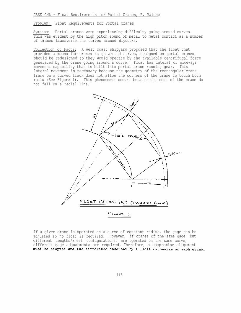
CASE CN6 - Float Requirements for Portal Cranes, P. Malone
Problem: Float Requirements for Portal Cranes
Symptom: Portal cranes were experiencing difficulty going around curves.This was evident by the high pitch sound of metal to metal contact as a numberof cranes transverse the curves around drydocks.
Collection of Facts: A west coast shipyard proposed that the float thatprovides a means for cranes to go around curves, designed on portal cranes,should be redesigned so they would operate by the available centrifugal forcegenerated by the crane going around a curve. Float has lateral or sidewaysmovement capability that is built into portal crane running gear. Thislateral movement is necessary because the geometry of the rectangular craneframe on a curved track does not allow the corners of the crane to touch bothrails (See Figure 1). This phenomenon occurs because the ends of the crane donot fall on a radial line.
If a given crane is operated on a curve of constant radius, the gage can beadjusted so no float is required. However, if cranes of the same gage, butdifferent lengths/wheel configurations, are operated on the same curve,different gage adjustments are required. Therefore, a compromise alignment
112

CASE CN7 - Rotate Structures on Portal and Floating Cranes, P. Malone
Problem: Stability of Rotate Structures on Portal and Floating Cranes forhandling critical loads.
Symptom: Some of the rollers that provided support under all loadingconditions lifted off the supporting structure during load test andevaluations.
Solution: A finite element model of typical portal frame was analyzed. Theresults of this analysis indicated that the portal frame was flexible and thatthe rollers carried load in proportion to the stiffness of the supportingmember. The rotate structure (upper structure) housed all of the machineryincluding the power plant. Because of the requirement to maintain alignmentof installed equipment, the rotate structure is constructed very rigid andtherefore when loaded, does not deflect to the same degree as the portalframe.
Based on the above information and varied field trips a procedure was set upto evaluate existing portal and floating cranes with key points of evaluationas follows:
1. Park the crane on the level section of the track with the boomparallel to the track (this provides the most stable conditions forstability analysis).
2. For NAVFAC designed portal cranes with the 125% test load,check rollers of the least loaded quadrant for contact with therotate structure and portal frame. If rollers make contact withboth structures, stability is satisfactory.
3. If rollers do not make contact with the rotate structure or theportal frame check the center steadment nut for contact with theportal frame. If clearance is maintained between steadment nut andportal frame, stability is satisfactory.
4. If contact is made between center steadment nut and portalframe, an engineering evaluation is required to determine thesuitability of the crane for service at the existing rated load.
113
CASE PS1 - Failure of Barbed Ribbon Tape, J. Cecilio
Problem: Failure of Barbed Ribbon Security Tape
Symptom: Failure-breaking apart of barbed ribbon security tape.
Collection of Facts: Specification MIL-B-52775 general purpose barbed tapeobstacle (GPBTO) specified 3 types of material for the manufacture of thetape. Of these, the Navy has been specifying Type III. This allowed the useof 201 and 301 stainless steel. The cold working of the ribbon by crimpingthe edge to obtain a curve in the plain of the ribbon suffered stresscorrosion cracking in these crimps. Fatigue propogated the cracks across theribbon, causing failure.
Solution: Laboratory evaluation (NRL) showed that 316 stainless steel wouldperform satisfactorily if manufactured by the same process. The laboratory atKeyport, WA. (NUWFS) showed that proper care in installation wouldsatisfactorily extend the fatigue life.
Specification MIL-B-52775 has been revised adding a Type VI material 316SS forNavy use when exposed to a marine or evergreen acid environment.
CASE PS2 - Vehicle Barriers, J. V. Tyrrell
Problem: Providing adequate vehicle barriers to prevent unauthorized entry.
Symptoms: Unsatisfactory performance, excessive costs.
Collection of Facts: Terrorism and overt unauthorized entry are becoming anincreasingly common problem. There are many patented and proprietary systemsbeing offered to capitalize on the sudden demand (5/85).
Solution: In order to design an effective barrier, the size, weight, andspeed of the vehicle must be considered. A simple trench or a berm cansometimes be very effective. Heavy blocks (concrete, etc.) or planters can beused. For new facilities, it may be possible to provide a grade separation bymeans of a low retaining wall along the perimeter to be protected. There isno value in providing an expensive gate control if the adjacent perimeter isnot equally resistant.
114
CASE PS3 - Failure of Barbed Tape Obstacle, J. Cecilio
Problem: Failure of Barbed Tape Obstacle from SWEF PACSUB Base, Bangor
Collection Of Facts: The perimeter fence at the main limited area andremote magazine area approximately 1,800 feet in length. There was over400 breaks in the barbed tape in the main limited area. All the breaksoccurred in the inner coil.
The installation uses a dual coil of 30/24 barbed tape fastened betweenthe "Y" Outriggers on a chain link fence. Breaking and failure of thestainless steel barbed tape fence topping has occurred at several othersites where high winds have been encountered. Corrosion and pitting ofthe stainless steel has also been observed where the material wasinstalled in a marine atmosphere.
Laboratory analysis has indicated that failure appeared to be caused byfatigue in the defamed areas in the barbed tape. Stress concentrationwas set up in the deformed area due to crimping and cracks were initiatedin this area when the tape was subjected to service load induced by winds,temperature and vibration. In addition, improper installation andfastening of the barbed tape to the fence structures was reported to havecaused excessive flexing and movement resulting in acceleration of thefatigue and breakage. The black plastic strapping has also been found todeteriorate and break, which then leads to excessive movement and flexingof the barbed tape under wind conditions.
Solution: Based on the above problem, type specification was modified.Plastic strapping was replaced with steel wire rope. Formalize andprovide installation procedures for the barbed tape fence topping.Specify types of stainless steel and manufacturing procedures to insure amore uniform product with better fatigue and corrosion resistance.
115
ARCHITECTURAL
CASE A1 - Roofing and Waterproofing, C. B. Key
Problem: Leaking Ammunition Storage Magazines
Collection of Facts: The structures are corrugated steel, sectionsdesigned to be constructed at grade level and covered with earth to resistpromulgation of exploding adjacent magazines in the event the contents ofone or more magazines were exploded. The design was considered to beeconomically feasible for construction in remote locations. However, theyhave never been absolutely water tight. It was expected that some rainwater would perk through the soil cover and find it's way into themagazines. With the advent of new weapons and missiles that are water andhumidity sensitive, it was required that magazines be absolutely watertight.
Solution: A fluid applied elastomeric waterproofing system was applied tothe outer surface of the corrugated steel magazines. A protection fabricwas placed over the waterproofing membrane to preclude damage to themembrane. A six inch thick aggregate drainage course was placed over theprotection fabric. This allowed water to drain down each side of thebarrel shaped structure and be collected by drain tiles parallel to eachside of the structure. The drain tiles carried the water out through thehead wall to a storm drain.
CASE A2 - Roofing and Waterproofing, C. B. Key
Problems: Slippage of built-up roofing
Collection of Facts: A built-up roofing membrane show signs of slippage.This was evident by the appearance of breaks in the aggregate surfacingparallel to the felts. Slippage is caused by using a type of bitumenhaving a softening point too low for the slope of the roof on which it isused. This roofing membrane was installed over roof insulation as are 90%of all built-up roofs. Since the slope did not exceed one inch per foot,wood nailers for backnailing the felts were not provided.
Solution: Aggregate was removed in lines approximately sixteen incheswide, eight feet apart, parallel to the slope of the roof. Nails weredriven through the roofing felts approximately twelve inches on centerdown the center of each line where aggregate had been removed. Strippingfelts four inches and twelve inches respectively were installed in bitumenover the nails up each line. Bare areas were then flood coated with hotbitumen and aggregate embedded. The nails served as shear pins andstopped the slippage of the felts.
116
CASE A3 - Roofing and Waterproofing, C. B. Key
Problem: Alligatoring of aluminum pigmented asphaltic roof coating
Collection of Facts: Within three months after an aluminum pigmentedasphaltic coating was applied on a smooth surfaced built-up roof, it beganalligatoring. This was a new built-up roof. A glaze coat of asphalt hadbeen applied to the surface of the built-up roof as a temporary protectionof the felts during construction. The glaze coat of asphalt had not beenleft exposed to the weather long enough to oxidize and still possess coldflow properties. This is what caused the alligatoring in the aluminumpigmented asphaltic coating.
Solution: The roof coating was allowed to continue alligatoring forapproximately six months, at which time the alligatoring stopped. This isbecause the asphalt was allowed to oxidize. The roof was recoated withaluminum pigmented asphaltic coating and there were no subsequent problems.
CASE A4 - Roofing and Waterproofing, C. B. Key
Problem: Wind blown aggregate surfacing on built-up roofing
Collection of Facts: Wind blown aggregate on built-up roofing in Guamcaused damage to automobiles and other structures during typhoons.Membrane felts were left bare and unprotected from ultraviolet rays of thesun which deteriorate the felts.
Solution: Double aggregate surfacing was used. The gravel was coatedwith a fine spray of kerosene to improve adhesion. The aggregate wasapplied in two layers. The first layer consisted of four hundred poundsof gravel embedded in sixty pounds of hot asphalt per one hundred squarefeet. The second layer consisted of three hundred pounds of gravelembedded in eighty pounds of hot asphalt per one hundred square feet. Allloose gravel was removed.
CASE A5 - Roofing and Waterproofing, C. B. Key
Problem: Poor adhesion and blistering of built-up roofing on highmoisture content decks.
Collection of Facts: When built-up roofing is hot-mopped to high moisturecontent decks, e.g., gypsum, lightweight insulating concrete, the roofingsystem resulted in poor adhesion to the deck and often resulted inblistering.
Solution: Mechanical fastening of an inorganic base sheet or vented basesheet was found to eliminate this problem. Subsequent plies of roofingfelt were hot-mopped to the base sheet.
CASE A6 - Roofing and Waterproofing, C. B. Key
Problem: Blistering of built-up roofing when applied over polyurethane roofinsulation.
Collection of Facts: In the latter seventies, many built-up roofs appliedover polyurethane insulation were noted to produce blisters at the interfacebetween the insulation and the first layer of felt. The blistering wasbelieved to be caused by moisture in the facing felt of the insulation oroffgasing of the polyurethane insulation. None of these theories were everproven.
Solution: This problem is eliminated by placing a thin layer of fiberousglass, perlite board, or mineral fiber board insulation between thepolyurethane insulation and the first layer of roofing felt. It is purelyacademic to prove whether the cause of blistering is offgasing or moisturevapor. However, a porous insulation, in contrast to a closed cell insulationlike polyurethane, allows any gaseous or vapor pressures to dissipatelaterally and reduce the concentrated effect that caused the blistering.
CASE A7 - Roofing and Waterproofing, C. B. Key
Problem: Determining the correct temperature for heating asphalt used inbuilt-up roofing.
Collection of Facts: Until the oil embargo in the early seventies, imperialtemperatures specified in ASTM D-312 were satisfactory for heating asphalt foruse in built-up roofing without producing any adverse effects. However, whenwe began acquiring oil from different sources, the asphalt derived from thesecrudes produced unreliable characteristics when heated in accordance withthese imperial temperatures. This often resulted in lowering the softeningpoint of the asphalt because it was heated above the actual temperaturerequired. The results were that the asphalt and roofing membrane would slidedown the roof. Some asphalts also required hotter temperatures thanrecommended in ASTM D-312 to obtain proper adhesion.
Solution: It was determined in the roofing industry that a more reliablemethod of obtaining the right temperature at which asphalt should be heatedfor proper application was based on viscosity. The concept of EquiviscousTemperature (EVT) has replaced the use of imperial temperatures in the roofingindustry. The EVT is the temperature at which the viscosity is 125centistokes when tested in accordance with the requirements of ASTM D-2170.The proper temperature for application of asphalt is a range betweentwenty-five degrees Fahrenheit above the EVT and twenty-five degreesFahrenheit below the EVT. Asphalt manufacturers' labels or bill of lading arenow required to provide the EVT.
118

CASE A8 - Roofing and Waterproofing, C. B. Key
Problem: Retarders for roofing.
Collection of Facts: Vapor drive is always from hot to cold. A vapor retardershould not be used in a roof assembly unless it is necessary. If moisture istrapped between a vapor retarder and the roofing membrane, it could causeblistering of the membrane, delamination of the felt plies, and premature rooffailure. If a vapor retarder is needed and not used, the vapor drive couldforce moisture into the insulation reducing the "R" value of the insulationand if organic felts are used, moisture can be wicked into the felt plies.This could result in early roof failure.
Solution: Only use a vapor retarder when the average January temperature is40 degrees Fahrenheit or below, and the inside relative humidity is 45% orhigher. Never use a vapor retarder in a roof assembly over a cold storagefacility.
CASE A9 - Roofing and Waterproofing, C. B. Key
Problem: Lack of information on roofing materials used on construction.
Collection of Facts: Roof maintenance personnel, inspectors, consultants, andcontractors performing work on roofs after original construction need to knowwhat types of materials the roofs are constructed of, to assure use ofcompatible materials. If the wrong materials are used, it could cause damageto the roofing. The contract specifications require that the Contractorprovide an information card near the roof access describing the types ofmaterials used in the roof construction. However, this is not being enforced,e.g., roofing inspections at TRIDENT Base, Kings Bay revealed that not onebuilding inspected had the required information posted.
Solution: Enforce the requirements of the contract. Make this a standarditem on the ROICC punch list.
CASE A10 - Roofing and Waterproofing, C. B. Key
Problem: Interior roof drain problems.
Collection of Facts: Leaks through the ceiling that are often thought to beroof leaks are frequently caused by leaks from roof drain piping above theceiling. In cold climates, interior roof drain piping systems provide thermalbridging in the building envelop which allows warm humid air to condensate onthe cold surface of the drain pipe system, causing moisture problems withinthe building. The effects of this phenomena are often confused with that of aroof leak. An attempt to rout-out roof drain piping above the ceiling maycause additional leaks due to vibration as these pipes are supported by pipehangers. Occasionally ceilings, walls and floor slabs have to be removed toprovide accessibility to the roof drain piping system to make repairs.Interior roof drain piping systems are more expensive to install and maintainthan perimeter roof drain systems.
119
Solution: Perimeter roof drain systems are preferred. As a general rule, allbuildings having a width of 100 feet or less should use perimeter roofdrains. For buildings that use interior roof drains, consideration should begiven to provide the following:
o Accessibility for future maintenance.o In cold climates insulating roof drain piping above the ceiling.o Securing of roof drain piping above the ceiling adequately to prevent
leaks caused by vibration during routing-out.
CASE All - Roofing and Waterproofing, C. B. Key
Problem: Roofing Flashing Failures.
Collection of Facts: Experience has shown that the majority of leaks inroofing systems occur at flashings. If the problem is not detected andrepaired soon enough, it could result in serious and costly damage to the roofassembly, building structure, and interior finishes and contents. Theinconvenience and frustrations of building users are transformed into lowmorale and lost productivity of the organization. Although the roofinggenerally represents only 2% of the total building cost, over 50% of alldesign and construction contract litigation results from roofing problems.There is nothing more embarrassing to a designer, contractor, or buildingowner than to have a roof leak in what otherwise appears to be a well designedand constructed building, representing a tremendous capital investment. Thenthere is repair or replacement cost for the roofing system and relateddamages. The cost of roofing replacement alone can run from $250 to $500 asquare (100 sq.ft.) depending on the type of roofing and complexity of thejob. The Lessons Learned are that flashings fail generally for one of tworeasons: (1) failure to incorporate provisions to accommodate differentialmovement resulting from thermal expansion and contraction or deflection; and(2) failure to incorporate the most maintenance free design concepts.Preventative maintenance is very seldom accomplished and is generally onlyprovided in a crisis when the roof leak is visible and disturbing within thebuilding.
Solution: It is the design philosophy of the Naval Facilities EngineeringCommand to incorporate features in flashing details that will accommodatedifferential movement and provide the most maintenance free design concepts.Specific examples are provided as follows:
a. Minimize the number of penetrations through the roof by groupingpipes and conduits into fewer strategic locations. See attachment 1.
b. Assure that penetrations do not occur at low points of the roof.
c. Do not use pitch pockets. See attachments 2 and 3. Pitch pocketsrequire frequent inspection and maintenance to maintain a waterproofseal. Use flashing collars with umbrella flashings. See attachment4.
d.
e.
f.
g.
h.
i.
Do not use surface applied cap flashings. See attachment 5. Surfaceapplied cap flashings have a high rate of failure. Install all capflashings in reglets raked in masonry or cut or cast into concrete.See attachment 6.
Locate vent, stacks and other individual penetrations through the roofnot less than 18 inches apart, and from walls and other verticalsurfaces. See attachment 7. Flashings for vent stacks should be asillustrated in attachment 8.
Use perimeter roof drains in lieu of interior roof drains whenpossible. See attachment 9. If interior roof drains are absolutelynecessary, provide a means of expansion between roof drains andleaders to allow the roof drain to move with the roof assembly whensubjected to allowable deflection. When this movement is restricted,it can break flashing connections between the roof drain and roofingmembrane, allowing water to enter.
Elevate metal roof edges to keep metal work above the water line.See attachments 10 and 11. Do not strip flash metal items longerthan 2 feet into the roofing membrane. See attachment 12.
Install roofing expansion joint covers above the water line. Seeattachments 13 and 14.
Where there is potential for deflection of the roof assembly atabutting non-supporting walls and penetrations, design flashings toallow for differential vertical movement. See attachments 15, 16 and17.
121
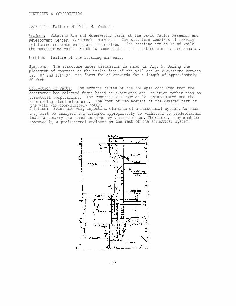
CONTRACTS & CONSTRUCTION
CASE CC1 - Failure of Wall, M. Yachnis
Project: Rotating Arm and Maneuvering Basin at the David Taylor Research andDevelopment Center, Carderock, Maryland. The structure consists of heavilyreinforced concrete walls and floor slabs. The rotating arm is round whilethe maneuvering basin, which is connected to the rotating arm, is rectangular.
Problem: Failure of the rotating arm wall.
Symptoms: The structure under discussion is shown in Fig. 5. During theplacement of concrete on the inside face of the wall and at elevations between128'-0" and 131'-9", the forms failed outwards for a length of approximately20 feet.
Collection of Facts: The experts review of the collapse concluded that thecontractor had selected forms based on experience and intuition rather than onstructural computations. The concrete was completely disintegrated and thereinforcing steel misplaced. The cost of replacement of the damaged part ofthe wall was approximately $500K.Solution: Forms are very important elements of a structural system. As such,they must be analyzed and designed appropriately to withstand to predeterminedloads and carry the stresses given by various codes. Therefore, they must beapproved by a professional engineer as the rest of the structural system.
CASE CC2 - Contractual Dispute-Light Pole, M. Yachnis
Problem: Contractual dispute on flood lighting pole section at Naval Academy,Annapolis, Maryland.
Symptoms: Aggravation.
Collection of Facts: Specification calls for a tubular section for a floodlighting pole. Drawings were shown a tubular pipe section. Contractorprovided an octagonal section which met the specifications.
Solution: Be careful that there is a complete agreement between plans andspecifications.
CASE CC3 - Substitution for Design Requirements, J. V. Tyrrell
Problem: Improper substitution for design requirements.
Collection of Facts: This problem is one that is continually repeated whenfield personnel approve substitutions without first checking with thedesigner. One instance involved a 1.5 million gallon water sphere indicatedat the Naval Oceangraphic Research Station, Lewis, Del. The design gaveapproximate dimensions and specified the section modulus and moment of inertiaof the stem. A manufacturer proposed a substitution using a smaller diameterstem which provided a section modulus very close to that specified but amoment of inertia considerably less. The substitution was accepted by theROICC. The construction was substantially completed and the system was beingtested when a hurricane passed close to the activity. When the main force ofthe stem was about 1 hour from the activity, the ROICC called to report thatthe sphere was swaying as much as 15 feet and wanted to know if he shouldattempt to empty it. He was told to clear the area and hope for the best.Fortunately, the structure survived and has been in operation for over 20years.
Solution: Many cases do not have a happy ending like the one cited. Fieldpersonnel should not approve any substantial changes in design withoutconsulting the designer. Often it is not apparent that the chance is"substantial", therefore it is advisable to contact the designer about changewhenever possible. For a MCON project, the contact should be with the EIC atthe NAVFAC Engineering Field Division.
123
CASE CC4 - Acceptance of Off-the-Shelf Structures, J. V. Tyrrell
Problem: Acceptance of structures not designed for the site.
Symptoms: Structural distress; change orders; increases in contract cost.
Collection of Facts: Sometimes off-the-shelf items will provide the mosteconomical solution to a design problem. Some of these items are actuallypre-engineered but not stockpiled in great quantities and instead fabricatedwhen ordered. For this type of structure, manufacturer's data is usuallyavailable showing what loadings were considered in design. If the designloading is not carefully checked against the intended use and the prevailingsite conditions, the structure may prove unsatisfactory.
The need for verifying the design may seem self-evident, but we have manycases where inadequate structures were acquired or contracted for before theinadequacies were discovered. Apparently there is some inclination to acceptwhatever is commercially available without carefully considering therequirement.
Solution: When using off-the-shelf or pre-engineered structures, check themfor the loadings intended including environmental loadings at the site (wind,snow, earthquake, soil conditions, etc.). If the structure is not adequate,do not use it unless the manufacturer modifies it or you expect to reinforceit separately. The cost of modification should be included in the project.
CASE CC5 - Erection of Cantilever Hangar, J. V. Tyrrell
Problem: Collapse during erection.
Collection of Facts: A typical cantilever type hangar with tension strutsuspender was being erected, at NAS Miramar, using scaffolding and jacks toposition the cantilever ends at the correct elevation before connecting thesuspender. This process had apparently been successfully used previously. Inthis case, one of the trusses slipped off of the jack creating a dominocollapse and resulting in injury to personnel. Several causes were possible.This method inherently involves lateral forces when two adjacent trusses arejacked to different elevations. The scaffolding is designed to minimizeweight and has little reserve strength. It was not capable of sustaining thetruss when it toppled and, consequently, massive collapse followed.
Solution: This method of erection is not recommended. Instead, it issuggested that the tension suspenders be connected immediately with aprovision for adjustment in the splice. The trusses can then be jacked toproper elevation without the possibility of dropping the structure. Erectionmethods are usually the contractor's domain; however, at a minimum, anycontractor should be made aware of the potential difficulties and at least berequired to submit a detailed plan and sequence for approval. If jacking isattempted before connection of the suspenders, the scaffolding should becarefully checked, provision should be made to brace the scaffolding and thejacks, and the maximum difference in elevation permitted should be establishedby structural calculations.
124
CASE CC6 - Tower Base Plate, E. Mifflin
Problem: Excessive machining.
Symptom: A base plate in an insulator replacement assembly was found to beinadequate.
Collection of Facts: Another plate of much better strength was procured by agovernment official. This higher strength plate was one (1) inch thicker thanthe original, so the procurer specified the plate be machined to the thinnerthickness. Had the official and/or his agent consulted with the engineer whodiscovered the original deficiency, the extra machining could have beenomitted. The extra machining at least tripled the cost of the material.
Solution: Keep the technical people informed. They may be able to help savesome money.
CASE CC7 - Specification Definition for Fill, A. H. Wu
Problem: Interpretation of 4 inches of "porous fill" to be installed under a5 inches concrete slab. Contractor interpreted the porous fill as being aborrow sand or clean sand in his bid, and he is claiming $8,600 for a changeorder for using concrete sand as porous fill as directed by the ROICC.
Collection of Facts: The spec did not specify the requirement for "porousfill." However, the legend and symbol used in contract drawings indicate theporous fill is coarse gravel.
ASTM C 33 No. 57 size material should have been defined as "concrete gravel",not “concrete sand". This was an error in the specification. The barrowmaterial (SM or SC) which the contractor planned to use as compacted fill wasalso planned for use as porous fill. Such a deviation is not permissiblebecause it would not comply with the requirements on the contract drawings.
Solution: The porous fill should be interpreted as gravel material, andspecified as such, with the size ranging from l/4" to 2-l/2" or other similarmaterial selected by the designer. Be careful in specifying porous fill.ROICC's should check with design EIC when interpreting contract requirements.
CASE CC8 - Sewer Pipes, A. H. Wu
Problem: There was a contract dispute regarding requirements for a stormdrain placed at the Anacostia Naval Station. The contractor argues that waterwas not a problem at the Anacostia jobsite.
Symptoms: The contractor contends that the specification requirement for adewatering system is to prevent the sides and surface of the excavation frombecoming soft. Since this did not happen, he felt he had fulfilled the intentof the contract. Furthermore, the contractor contended that the requirementto remove water to one foot below the trench floor is unrealistic since thesoil is clay-like and impervious. The contractor argued that the conditionsin the trench bottom were abnormally soft, not due to water content, and that
125
a change order and direction from the government were required to allow him toproceed. The contractor stated that the contract requires him to useexcavated material for backfill. The contract does not state that he musttreat or dry the soil in any special way. Therefore, he is not responsible ifcompaction requirements are not met and if the pipe is bowed and misaligned.The contractor felt he has performed his work in fulfillment of the intent ofthe contract and since the work is unsatisfactory to the Government, a changeorder should be executed for time and money for him to proceed.
Collection of Facts: The Government's position was that the contractor hasnot fulfilled the requirements of the contract and has not fulfilled theintent of the contract by not producing useable, satisfactory work. Thecontract states that a dewatering system is to be in place and operatingbefore excavation. This has not happened. The Government felt that adewatering system before excavation would render the excavated materialsuitable for backfill and allow it to meet compaction requirements. Adewatering plan would affect the softness of the trench floor, and inconjunction with excavation methods described in the contract, will provide amore stable bed for the pipeline and reduce the additional gravel bed thecontractor claims is required. The contractor has not excavated the trench inconformance with the contract specifications.
Solution: Fill the open trench area as soon as possible and provide floodprotection from the river. Leaving the trench open was viewed as a safetyhazard endangering the lives of personnel working on the base, as well as apotential risk to property.
The contractor was directed several times to fulfill the requirements of thecontract. He has been reminded that the contract does not specify that hemust use a wellpoint system and that the selection of another system is hischoice as long as the dewatering and compaction requirements are met. To thetime of this writing, the matter has not been resolved.
It is felt that the specification was clear and adequate. Therefore, theGovernment may initiate default proceedings for non-performance. Allrequirements and provisions of Clause 5 of the General Provisions should befollowed.
CASE CC9 - Failure of the Outlooker-Handrail System, M. Yachnis
Problem: Failure of the Outlooker-Handrail System, on BEQ at Henderson Hall
Symptoms: Cracks in concrete in the area of the anchoring studs.
Collection of Facts: At 2:OO p.m. on August 24, 1981, the connections betweenthe balcony cantilever beams - outlookers - and the concrete handrails failedcatastrophically causing the third floor handrails on the outside balcony ofthe south building (Fig. 20) to fall on the handrails of the second floorwhich in turn fell on the ground. Ten of the outlookers totally failed andfifteen others suffered damage of various magnitude.
An engineering investigation, which included destructive andnon-destructive testing, was performed.
126
The Bachelor Enlisted Men Quarters at Henderson Hall consist of a twolevel parking garage and a multi-story barracks and dining facility. Theconfiguration of the total structure is such that the North Building and SouthBuilding enclose a central plaza which is located directly above the garage.
The structural framing of the garage consists of a reinforced concreteslab, beam and column system. The barracks structural system consists ofprecast prestressed concrete hollow core planks supported on bearing concretemasonry unit walls. Cantilevered beams (out lookers) support the balconyslabs. These beams were poured integrally with the exterior columns. Precastconcrete panels 5' -9" high and with thickness varying from 4” to 6 l/2"constitute the handrails which are supported by the outlookers. The handrailsare connected to the outlookers by two steel angles welded to plates which areanchored to both the handrails and outlookers by steel studs.
An extensive test program was initiated which included:
1. Destructive Testing
Concrete cores were taken from the damaged beams and were subjected tocompressive tests. The dimensions of the cores are as follows: Diameter:3.7 "; Height 7.4"; Area: 1O.75 sq. inches. It was found that the T-daycompressive strength was approximately 4,600 psi which exceeded the designstress of 4,000 psi. The steel of #3 stirrups was tested with resultsexceeding 100,000 psi.
2. Non-Destructive Testing
Compressive strength tests were performed on the structural members byusing the rebound (Swiss) hammer. The average compressive strength wasapproximately equal to 4,000 psi. Core tests, however, demonstratedcompressive strength greater than 4,000 psi.
The outlookers were measured to be 2 5/8" longer than the constructiondrawings required. Even though this increase in length of the outlookersresults in overstressing of the tensile reinforcement, it is not related tothe subject failure.
The exact location of the stirrups in the outlookers was found by using areinforcement locator (Magnetometer). Some of the stirrups were not locatedin accordance with the construction drawings. However, this condition did notreduce the loading capacity of the outlookers.
The welds at the connections between the outlookers and the handrails werevisually inspected. Magnetic Particle Inspection (MT) or Dye PenetrantInspection (PT) were recommended for some suspect welds.
Computations demonstrated that the tensile reinforcement is slightlyoverstressed while the web reinforcement does not meet the applicable ACICode. The Code allows a waiver under the condition of performing a strengthevaluation (Load Test).
127
3. Test Loading
The test loading was performed in accordance with part 6, Chapter 20"Strength Evaluation of Existing Structures“ of the American ConcreteInstitute Building Code (ACI 318-77). At section 20.4.3, the Code states“That portion of the structure selected for loading shall be subject to atotal load, including dead loads already acting, equivalent to 0.85 (1.4 D +1.7 L) where D = Dead Load and L = Live Load.
(1) Method of Loading
Falsework was used for safety precautions (Fig. 21). A schematic of themethod of loading is shown in Fig. 22 and the various increments in Fig.23. Deflections were measured by using deflection gages capable ofmeasuring from .001" to 1.0". The deflection measurements are as follows:
Increment Deflection in Inches
1 .00122 .0033 .0036
Full Load .084After 36 Hours .O996Unloaded .0072
Total predicted deflection was .095" which was greater than the deflectionunder full load. Creep was observed 36 hours after completion of testing.The deflection differential was 0.0156" within accepted limits. Almost fullrecovery of the outlooker demonstrated that no yield occurred in the maintensile reinforcement. Visual inspection showed no shear cracks or diagonaltension cracks during testing. Few hairline cracks in the tension areaappeared during maximum loading which were closed totally during the reboundperiod.
Solution:
1. Anchoring Studs.
Symptom: The separation of anchoring studs from the concrete shown inEnclosure 2 is evidence of lack of sufficient embedment or concrete cover.
Remedy: Provide additional embedment and concrete cover.
2. Bars at the end of outlooker (Nose Bars).
Symptom: Lack of nose bars.
Remedy: Add nose bars.
3. Beams which will not be restored.
Symptom: Hairy shear cracks.
Remedy: Seal cracks with mortar to prevent moisture and corrosion of steel.
128
4. Reinforcing Steel.
Symptom: Small cracks may be evidence that stirrups and tensile steel may beinadequate.
Remedy: Perform a load test on an outlooker and measure deflections. If loadtest demonstrates inadequacy of the outlooker, increase the strength byappropriate methods.
Based on the test results, it was determined that the outlooker wasadequate to carry the design load. It is noted that the outlooker-handrailsystem is anchored without any allowance for expansion and contraction. It ispredicted that during periods of large temperature differentials, expansioncracks will appear. For this reason, it is strongly recommended that amonitoring system be instituted which will report unusual movements andsubsequent cracks.
129
CASE MA1 - Shipyard Items Requiring Maintenance, T. Hayes
Problem: Maintenance of equipment at most Naval shipyards is poor.
Collection of Facts: Very little effort has been devoted by shipyards tomaintenance of equipment. At almost every shipyard visited, especially inthe area of drydocks, there is blatant evidence of neglect of equipment.Utility lines are excessively corroded, capstan pits are filled with waterpacking glands on valves and pump leak, valves and pumps are excessivelycorroded, flange bolts and nuts are excessively corroded, pumps are in need of
opened or missing, large chunks of concrete ark hanging loose on-drydockwalls, atlas, galleries or coping. These items are not included in thedrydock safety certification program because they do not directly affect thesafety of ships in the drydock. However, neglect of these items results inhazards to personnel or in costly replacements. In many cases, the shipyardshave a preventative maintenance program. However, care for the aforementioned
greasing or changing of oil for mechanical equipment.
in the drydock area.
CASE MA2 - Maintenance for Roofs, C. B. Key
Problem: Roof failure due to lack of maintenance.
Collection of Facts: Many roofs fail prematurely due to lack of maintenance,"out of sight, out of mind until they leak". Field investigations of roofingat TRIDENT Base Bangor in June of 1984 revealed many roofs in need ofmaintenance, e.g., punctured base flashings, erosion of aggregate surfacing,roof drain sumps filled with debris. These things start out as minor problemsbut, left unattended, result in major roof problems.
Solution: More frequent routine maintenance by qualified maintenancepersonnel. Each roof should be inspected not less than twice a year bypersonnel equipped to perform the necessary routine maintenance during theinspection. Maintenance that will require more planning and preparationshould be accomplished as soon as possible.
130

PAINTS AND COATINGS
CASE PS1 - Floor Paint, P. Malone
Problem: Poor performance of a product recommended by a salesman.
Symptom: Life of the special floor paint was well below that promised by theproduct salesman.
Collection of Facts: The floor paint was applied in accordance with theinstruction provided by the manufacturer. The salesman's classic comment was,"I did not know you were going to use it in that shop area," although hepersonally toured the area when the recommendation was made.
Solution: Use no new product until proof of performance has been established.
131
*U.S. GOVERNMENT PRINTING OFFICE: 1985 0 - 488-384