natural convection flows in porous trapezoidal enclosures with
TRANSCRIPT

International Journal of Heat and Mass Transfer 52 (2009) 4612–4623
Contents lists available at ScienceDirect
International Journal of Heat and Mass Transfer
journal homepage: www.elsevier .com/locate / i jhmt
Natural convection flows in porous trapezoidal enclosures with variousinclination angles
Tanmay Basak a, S. Roy b, Amit Singh b, A.R. Balakrishnan a,*
a Department of Chemical Engineering, Indian Institute of Technology Madras, Chennai 600036, Indiab Department of Mathematics, Indian Institute of Technology Madras, Chennai 600036, India
a r t i c l e i n f o
Article history:Received 14 May 2008Received in revised form 19 January 2009Accepted 22 January 2009Available online 4 May 2009
Keywords:Penalty finite element methodNatural convectionPorous mediumTrapezoidal cavityVarious anglesUniform and non-uniform heating
0017-9310/$ - see front matter � 2009 Elsevier Ltd. Adoi:10.1016/j.ijheatmasstransfer.2009.01.050
* Corresponding author. Tel.: +91 0442257 4154; faE-mail addresses: [email protected] (T. Basak)
[email protected] (A.R. Balakrishnan).
a b s t r a c t
Simulations were carried out using penalty finite element analysis with bi-quadratic elements to inves-tigate the influence of uniform and non-uniform heating of bottom wall within a trapezoidal enclosure ofvarious inclination angles ðuÞ. Parametric study has been carried out for a wide range of Rayleigh numberðRaÞ ð103
6 Ra 6 106Þ, Prandtl number ðPrÞ ð0:026 6 Pr 6 988:24Þ and Darcy number ðDaÞ ð10�36
Da 6 10�5Þ. Numerical results are presented in terms of stream functions, isotherm contours and Nusseltnumbers. The heat transfer is primarily due to conduction at lower values of Darcy number ðDaÞ and con-vection dominant heat transfer is observed at higher Da values. The intensity of circulation increases withincrease in Darcy number. Increase in the intensity of circulations and larger temperature gradient arealso observed with increase in u from 0� to 45� especially at larger Pr and Ra. Non-uniform heating ofthe bottom wall produces greater heat transfer rate at the center of the bottom wall than uniform heatingat all Rayleigh and Darcy numbers, but average Nusselt number is lower for non-uniform heating. Localheat transfer rates are found to be relatively greater for u ¼ 0�. It is observed that the local heat transferrate at the central portion of bottom wall is larger for non-uniform heating case. Average Nusselt numberplots show higher heat transfer rates at the bottom wall for u ¼ 0� as compared to u ¼ 45� and u ¼ 30�.It is observed that the average heat transfer rate at the bottom wall is found to be invariant with respectto u at higher Ra for non-uniform heating. Critical Rayleigh numbers for conduction dominant heattransfer cases have been obtained and the power law correlations between average Nusselt numberand Rayleigh numbers are presented for convection dominated regimes.
� 2009 Elsevier Ltd. All rights reserved.
1. Introduction
The convective motion driven by buoyancy forces is well-known natural phenomena, and has attracted much attention[1–11]. The phenomena of natural convection in enclosures canbe classified into two main groups – rectangular enclosures andnon-rectangular enclosures. However, the number of studies onnatural convection in porous non-rectangular geometries is verylimited. In this context, buoyancy driven phenomena in porousmedia are actively under investigation. Natural convection flowsare however particularly complex as they depend on severalparameters among which the geometry and thermophysical char-acteristics of the fluid are the most important. Also, various appli-cations depend on the product specification, shape of the containerand heating characteristics. Numerical modeling offers a way to re-duce expensive experiments. Most of the earlier modeling studies
ll rights reserved.
x: +91 0442257 0509., [email protected] (S. Roy),
were carried out with conductive heating because of the simplicityof analytical and numerical solutions.
A significant amount of literature is available on the convectionpatterns in enclosures filled with porous media [12–15]. Naturalconvection in an enclosure filled with two layers of porous mediawas investigated numerically by Merrikh and Mohamad [16]. Thefocus of this work is on the validity of the Darcy model. Tongand Subramanian [17] and Lauriat and Prasad [18] consideredBrinkman-extended Darcy model to examine the buoyancy effectson free convection in a vertical cavity. Brinkman-extended Darcymodel has been introduced by Brinkman [19] in order to accountfor the transition from Darcy flow to highly viscous flow at highpermeability values. However, Brinkman-extended Darcy modeldoes not provide adequate description for the transition from theporous medium flow to pure fluid flow. A model that bridges thegap between the Darcy and Navier–Stokes equations is theDarcy–Forchheimer model developed by Vafai and Tien [20]. Inaddition, Darcy–Forchheimer model also describes the effect ofinertia and viscous forces in the porous media and was usedby Poulikakos and Bejan [21] and Lauriat and Prasad [22] to

Nomenclature
Da Darcy numberg acceleration due to gravity, m s�2
k thermal conductivity, W m�1 K�1
H length/height of the trapezoidal cavity, mN total number of nodesNu local Nusselt numberp pressure, PaP dimensionless pressurePr Prandtl numberR Residual of weak formRa Rayleigh numberT temperature, KTh temperature of hot bottom wall, KTc temperature of cold inclined wall, Ku x component of velocityU x component of dimensionless velocityv y component of velocityV y component of dimensionless velocityX dimensionless distance along x coordinateY dimensionless distance along y coordinate
Greek symbolsa thermal diffusivity, m2 s�1
b volume expansion coefficient, K�1
c penalty parameterh dimensionless temperaturem kinematic viscosity, m2 s�1
q density, kg m�3
U basis functionsw stream functionn horizontal coordinate in a unit squareg vertical coordinate in a unit squareu angle of inclination of side walls
Subscriptsb bottom walll left wallr right walls side wall
T. Basak et al. / International Journal of Heat and Mass Transfer 52 (2009) 4612–4623 4613
investigate the natural convection in a vertical enclosure filledwith a porous medium.
A few earlier works have been carried out on natural convectionin complex porous geometries. Bortolozzi and Deiber [23] studiedthe two-field model for natural convection in porous media in rela-tion to the one-field model, based on the assumption of local ther-mal equilibrium. These models are used to evaluate heat transferthrough a porous medium of relatively high permeability containedin a vertical annulus. Numerical calculations are carried out for var-iable porosity and various correlations for the heat transfer coeffi-cient between solid and fluid phases are analyzed. Badruddinet al. [24] have studied the steady state heat transfer in a porousmedium fixed in a vertical annular cylinder. The Darcy model offlow was employed and heat transfer was assumed to take placeby natural convection and radiation. The governing equations weresolved using the finite element method. They found that if inter-phase heat transfer coefficient and modified conductivity ratio aremaintained at high values, then thermal equilibrium is approachedwith both solid and fluid phases having similar temperatures.
A few recent works are also based on various complex situa-tions in porous medium [25–27]. The effect of viscous dissipationhas been considered for Darcy model by Saeid and Pop [25]. Theirstudies show that the viscous dissipation effect reduces the heattransfer rate and the average Nusselt number in porous cavity de-creases with the increase of the viscous dissipation parameter. Re-cently, Basak et al. [26] studied numerically the natural convectionflows in a square cavity filled with a porous matrix for variousboundary conditions and wide range of parameters. Resultsshowed that non-uniform heating of the bottom wall producesgreater heat transfer rate at the center of the bottom wall than uni-form heating case for all Ra, but average Nu shows overall lowerheat transfer rates for non-uniform heating case.
Baytas and Pop [27] have studied natural convection on trape-zoidal porous enclosure with situations such as top enclosurebeing cooled, bottom surface being heated and the remainingtwo non-parallel plane sidewalls of the enclosure being adiabatic.Although their study deals with heat transfer analysis on variousapplication in trapezoidal porous spaces, a comprehensive analysison heat transfer and flow circulations for applications on extrac-tion of molten metals, salt water and olive oil confined within aporous bed is yet to appear in literature for various tilt angles.
The objective of the present study is to investigate the circula-tion and temperature distributions in various enclosures (trapezoi-dal or square) with uniformly and non-uniformly heated bottomplate and cooled side walls. The effect of geometry has been illus-trated for various angle of the sidewall varying within 0–45�. Theanalysis has been carried out for various materials with a rangeof Prandtl number ðPrÞ, e.g., molten metals ðPr ¼ 0:004—0:026Þ,gases ðPr ¼ 0:7—1Þ, salt water ðPr ¼ 1:7—13:7Þ, oils ðPr ¼50—103Þ, etc. whereas earlier literature primarily involve air andwater only. The thermal processing of various materials within aporous enclosure is quite important especially for separation orextraction purposes. The motivation of this study is to analyzethe practical situation where the vertical wall is at ambient tem-peratures and inside temperature is maintained high using anyheating system, while the top wall is insulated. The boundary con-ditions due to uniform heating correspond to jump discontinuitiesat corner points and similar boundary conditions were also used inearlier works on natural convection in square cavities [5,26]. Theboundary condition due to non-uniform heating has been repre-sented by sinusoidal distribution of temperature and this type ofboundary condition is particularly useful for processing moltenglass [28].
The geometry of the trapezoidal enclosure with boundary con-ditions is shown in Fig. 1a–c. In the current study, the Galerkin fi-nite element method is used with penalty parameter to solve thenon-linear coupled partial differential equations governing flowand temperature fields for both uniform and non-uniform heatingof the bottom wall. The Darcy–Forchheimer model without theForchheimer’s inertia term has been adopted. The jump disconti-nuities in Dirichlet type of wall boundary conditions at the cornerpoints correspond to computational singularities. In particular, thesingularities at the bottom corner nodes need special attention.Non-orthogonal grid generation has been done with iso-paramet-ric mapping [29,30]. An overview on grid generation usingiso-parametric mapping is given in Appendix A. The Galerkin finiteelement with iso-parametric mapping has been used based on thefact that automatically generated grid in a pseudo-square domainmakes the method robust for any complex geometry. Numericalresults are obtained to describe the circulation and temperaturedistributions within the domain and the heat transfer rate for boththe walls in terms of local and average Nusselt numbers. Local and

(a)
(b)
(c)
A B
CD
A B
CD
C D
ϕ
H
H
H
H
H
HA B
ϕ
Fig. 1. Schematic diagram of the physical system for (a) u ¼ 45� , (b) u ¼ 30� and(c) u ¼ 0� .
4614 T. Basak et al. / International Journal of Heat and Mass Transfer 52 (2009) 4612–4623
average Nusselt numbers have been evaluated using bi-quadraticbasis functions. The heat transfer effects have been illustratedbased on two cases: uniformly heated bottom wall and non-uni-formly heated bottom wall.
2. Mathematical formulation
Consider a trapezoidal cavity, filled with a porous medium, withthe left wall inclined at an angle u ¼ 45�;30� and 0� with the y-axisas seen in Fig. 1a, b and c, respectively. Thermophysical propertiesof the fluid in the flow field are assumed to be constant except thedensity variations causing a body force term in the momentumequation. The Boussinesq approximation is invoked the variationof fluid density with temperature and to couple in this way thetemperature field to the flow field. Further, it is assumed that thetemperature of the fluid phase is equal to the temperature of thesolid phase everywhere in the porous region and local thermalequilibrium (LTE) is applicable in the present investigation [13].Also, a velocity square term could be incorporated in the momen-tum equations to model the inertia effect which is more importantfor non-Darcy convective boundary layer flow over the surface of abody embedded in a high porosity media. However, this term hasbeen neglected in the present study because this study involvesthe natural convection flow in a cavity filled with a porous med-ium. Under these assumptions and following the earlier works[20,4] with the Forchheimer’s inertia term being neglected, thegoverning equations for steady two-dimensional natural convec-tion flow in the porous cavity using conservation of mass, momen-tum and energy in dimensionless form can be written as:
@U@Xþ @V@Y¼ 0 ð1Þ
U@U@Xþ V
@U@Y¼ � @P
@Xþ Pr
@2U
@X2 þ@2U
@Y2
!� Pr
DaU ð2Þ
U@V@Xþ V
@V@Y¼ � @P
@Yþ Pr
@2V
@X2 þ@2V
@Y2
!� Pr
DaV þ RaPrh ð3Þ
U@h@Xþ V
@h@Y¼ @2h
@X2 þ@2h
@Y2 ð4Þ
where
X ¼ xH; Y ¼ y
H; U ¼ uH
a; V ¼ vH
a; h ¼ T � Tc
Th � Tc
P ¼ pH2
qa2 ; Pr ¼ ma; Da ¼ K
H2 ; Ra ¼ gbðTh � TcÞH3
mað5Þ
The dimensionless form of the boundary conditions are:
U¼0; V ¼0; h¼1; or h¼ sinðpXÞ;8Y ¼0; 06X61U¼0; V ¼0; h¼0; 8XcosðuÞþYsinðuÞ¼0;06Y 61U¼0; V ¼0; h¼0; 8XcosðuÞ�YsinðuÞ¼ cosðuÞ;06Y 61
U¼0; V ¼0;@h@Y¼0; 8Y ¼1;�tanðuÞ6X61þ tanðuÞ: ð6Þ
3. Solution procedure
The momentum and energy balance equations (Eqs. (2)–(4))are solved using the Galerkin finite element method. The continu-ity equation (Eq. (1)) is used as a constraint due to mass conser-vation and this constraint may be used to obtain the pressuredistribution. In order to solve Eqs. (2) and (3), the penalty finiteelement method is used where the pressure P is eliminated bya penalty parameter c and the incompressibility criteria givenby Eq. (1) results in
P ¼ �c@U@Xþ @V@Y
� �ð7Þ
The continuity equation (Eq. (1)) is automatically satisfied forlarge values of c. Typical values of c that yield consistent solutionsare 107. Using Eq. (7), the momentum balance equations (Eqs. (2)and (3)) reduce to
U@U@Xþ V
@U@Y¼ c
@
@X@U@Xþ @V@Y
� �þ Pr
@2U
@X2 þ@2U
@Y2
!� Pr
DaU ð8Þ
and
U@V@Xþ V
@V@Y¼ c
@
@Y@U@Xþ @V@Y
� �þ Pr
@2V
@X2 þ@2V
@Y2
!� Pr
DaV
þ RaPrh ð9Þ
The system of equations (Eqs. (4), (8) and (9)) with boundaryconditions (Eq. (6)) are solved using Galerkin finite element meth-od [29]. Since the solution procedure is explained in an earlierwork [26], the detailed description is not included in this paper.The numerical solutions are obtained in terms of the velocity com-ponents ðU; VÞ and stream function ðwÞ is evaluated using the rela-tionship between the stream function ðwÞ and the velocitycomponents [31], where the stream function ðwÞ is defined in theusual way as U ¼ @w
@Y and V ¼ � @w@X. It may be noted that, the positive
sign of w denotes anti-clockwise circulation and the clockwise cir-culation is represented by the negative sign of w. The no-slip con-dition is valid at all boundaries as there is no cross flow, hencew ¼ 0 at the boundaries. For steady flow, stream lines are equiva-lent to the paths followed by the individual particles in the fluid.

X
Y
Y
Mapping
Mapping
1 4 7
2
3
6
9
85
1
2
3
4
5
6
7
8
9
X
η
η
(a)
(b)ξ
ξ
Global co−ordinate system Local co−ordinate system
Fig. 2. (a) The mapping of trapezoidal domain to a square domain in n—gcoordinate system and (b) the mapping of an individual element to a singleelement in n—g coordinate system.
T. Basak et al. / International Journal of Heat and Mass Transfer 52 (2009) 4612–4623 4615
The heat transfer coefficient in terms of the local Nusselt num-ber ðNuÞ is defined by
Nu ¼ � @h@n
ð10Þ
where n denotes the normal direction on a plane. The local Nusseltnumbers at bottom wall ðNubÞ, left wall ðNulÞ and right wall ðNurÞare defined as
Nub ¼X9
i¼1
hi@Ui
@Yð11Þ
Nul ¼X9
i¼1
hi cosu@Ui
@Xþ sinu
@Ui
@Y
� �ð12Þ
and
Nur ¼ �X9
i¼1
hi cosu@Ui
@X� sinu
@Ui
@Y
� �ð13Þ
The average Nusselt numbers at the bottom, left and right walls are
Nub ¼R 1
0 NubdX
Xj10¼Z 1
0NubdX ð14Þ
Nul ¼ cosuZ 1
cosu
0Nulds1 ð15Þ
and
Nur ¼ cosuZ 1
cosu
0Nurds2 ð16Þ
where ds1;ds2 is the small elemental lengths along the left and rightwalls, respectively.
4. Results and discussion
4.1. Numerical tests
The grid generation has been carried out by iso-parametricmapping and the detailed explanation is given in Appendix A.The computational domain consists of 20� 20 bi-quadratic ele-ments which correspond to 41� 41 grid points in n—g domain asseen in Fig. 2. The bi-quadratic elements with lesser number ofnodes smoothly capture the non-linear variations of the field vari-ables which are in contrast with finite difference solutions avail-able in the literature [27]. In order to assess the accuracy of thenumerical procedure, the algorithm has been benchmarked basedon the grid size for the fluid filled trapezoidal cavity [32]. Further,the result is in agreement with an earlier work [22] for poroussquare enclosure with heated side wall.
Numerical solutions are obtained for Ra ¼ 103—106; Pr ¼0:026—988:24 and Da ¼ 10�5—10�3 with uniform and non-uni-form heating of the bottom wall where two vertical walls arecooled and the top wall is well insulated. The jump discontinuityin Dirichlet type of boundary conditions at the corner point onthe bottom wall (see Fig. 1) corresponds to computational singu-larity. To ensure the convergence of the numerical solution to theexact solution, the grid sizes have been optimized and the resultspresented here are independent of grid sizes. In particular, the sin-gularity at the corner nodes of the bottom wall needs special atten-tion. The grid size dependent effect of the temperaturediscontinuity at the corner points on the local (and the overall)Nusselt numbers tend to increase as the mesh spacing at the corneris reduced. One of the ways for handling the problem is assumingthe average temperature of the two walls at the corner and keepingthe adjacent grid-nodes at the respective wall temperatures. How-ever, according to earlier work by Ganzarolli and Milanez [33], this
procedure is still grid dependent unless a sufficiently refined meshis implemented. Hence, once any corner formed by the intersectionof two differently heated boundary walls is assumed at the averagetemperature of the adjacent walls, the optimal grid size obtainedfor each configuration corresponds to the mesh spacing over whichfurther grid refinements lead to grid invariant results in both heattransfer rates and flow fields.
In the current investigation, Gaussian quadrature based finiteelement method provides the smooth solutions at the interior do-main including the corner regions as evaluation of residuals de-pends on interior Gauss points and thus the effect of cornernodes is less pronounced in the final solution. The present finiteelement approach offers special advantages on evaluation of localNusselt number at the bottom and side walls as the element basisfunctions are used to evaluate the heat flux.
4.2. Effects of Darcy number: uniform heating at bottom wall
Figs. 3–7 illustrate the stream function and isotherm contoursfor various Ra ¼ 103—106;Da ¼ 10�5—10�3 and Pr ¼ 0:026(molten metal), 7.2 (salt water) and 988.24 (olive oil) whenthe bottom wall is uniformly heated and the side walls arecooled while the top wall is well insulated. Due to the hot bot-tom wall, the fluid near that wall is hotter than the fluid nearthe cold wall and hence fluid near the hot bottom wall havelower density than that near the vertical wall. As a result, fluidmoves upward from the middle portion of the bottom walland flows down along the two cold side walls resulting in oppo-sitely rotating circulations inside the cavity. Results indicate thatthe streamlines and isotherms are strongly dependent on Darcynumber.
Fig. 3 displays the temperature and stream function contoursfor Da ¼ 10�5 and Ra ¼ 106 with Pr ¼ 7:2. In this case, the flow isseen to be very weak as observed from the stream function con-tours. The temperature contours are smooth and monotonic andthis indicates that heat transfer is primarily due to conduction. Iso-therms with h ¼ 0:1—0:4 occur symmetrically near the side wallsof the enclosure for u ¼ 45� (Fig. 3a). The other temperature con-tours with h P 0:5 are smooth curves symmetric with respect tovertical symmetrical line at the center. For u ¼ 30�, the isothermswith h ¼ 0:1—0:3 occur symmetrically near the side walls of the

0.5
0.7
0.9
0.3
0.2
0.1
0.1
0.2 0.3
(a)TEMPERATURE, θ
0.05 −0.05
0.25 −0.250.34 −0.34
0.12 −0.12
STREAM FUNCTION, ψ
0.4
0.6
0.8
0.2 0.2
(b) 0.05 −0.05
0.25 −0.250.32 −0.32
0.12 −0.12
0.2
0.4
0.6
0.9
0.1 0.1
(c)0.02 −0.02
0.1 −0.1
0.2 −0.2
0.05−0.05
Fig. 3. Contour plots for uniform bottom heating, hðX;0Þ ¼ 1, with Pr ¼ 7:2 (salt water), Ra ¼ 106 and Da ¼ 10�5 for (a) u ¼ 45� , (b) u ¼ 30� and (c) u ¼ 0� . Clockwise andanti-clockwise flows are shown via negative and positive signs of stream function, respectively.
0.5
0.70.9
0.40.2
0.3
0.1
(a) TEMPERATURE, θ
0.34 −0.34−0.25
0.05 0.15
−0.15
−0.05
0.25
STREAM FUNCTION, ψ
0.4
0.60.8
0.3
0.1
0.3 0.1
(b)
0.32
0.14 −0.14
−0.32
0.25−0.25
−0.050.05
0.2
0.4
0.60.8
0.1
0.1
(c)
0.6
0.40.2 −0.2
−0.5
−0.6
0.1
0.5
−0.4
−0.1
Fig. 4. Contour plots for uniform bottom heating, hðX;0Þ ¼ 1, with Pr ¼ 7:2 (salt water) and Da ¼ 10�3 for (a) u ¼ 45�; Ra ¼ 104, (b) u ¼ 30�; Ra ¼ 104 and (c)u ¼ 0�; Ra ¼ 3� 104. Clockwise and anti-clockwise flows are shown via negative and positive signs of stream function, respectively.
4616 T. Basak et al. / International Journal of Heat and Mass Transfer 52 (2009) 4612–4623
enclosure (Fig. 3b) whereas h P 0:4 are smooth curves symmetricwith respect to vertical symmetric line. For square cavityðu ¼ 0�Þ; h ¼ 0:1 is symmetric along the side walls and h P 0:2are smooth curves symmetric with respect to the central symmet-ric line (Fig. 3c). Increase in the intensity of circulations and largertemperature gradient are observed with increase in u from 0� to45�.
During conduction dominant heat transfer, the temperatureprofiles are almost invariant with respect to Ra and it is observedthat the significant convection is initiated corresponding to a crit-ical Ra. The critical Rayleigh number for the conduction dominantmode is found as Ra ¼ 104 for u ¼ 45�;30� and Ra ¼ 3� 104 foru ¼ 0� with Da ¼ 10�3 and Pr ¼ 7:2. At critical Ra, the distortionof the isotherm gradually increases and convection becomes
0.6
0.5 0.5
0.8
0.40.4
0.1 0.2
(a)TEMPERATURE, θ
1 −1
812
14 −14−12
−8
5 −5
STREAM FUNCTION, ψ
0.6
0.8
0.5 0.5
0.3 0.3
(b) 1 −18 −8
1412 −12
−14
5 −5
0.6
0.8
0.5 0.5
0.3
0.30.1
0.1
(c)15
101214 −14
−12−10−5
−1
1
−1
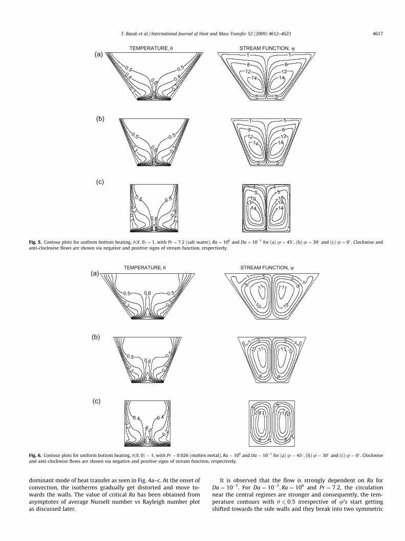
Fig. 5. Contour plots for uniform bottom heating, hðX; 0Þ ¼ 1, with Pr ¼ 7:2 (salt water), Ra ¼ 106 and Da ¼ 10�3 for (a) u ¼ 45� , (b) u ¼ 30� and (c) u ¼ 0� . Clockwise andanti-clockwise flows are shown via negative and positive signs of stream function, respectively.
0.6
0.8
0.5 0.50.3 0.3
(a)TEMPERATURE, θ
11 −11
10
−10
8 −8
5 −51 −1
STREAM FUNCTION, ψ
0.6
0.8
0.5 0.5
0.3 0.3
(b)
11 −1110
−10
8 −8
−551 −1
0.5
0.7
0.40.2
0.4
0.2
(c)11 −1110
5 −5 −10
8 −8 −22
Fig. 6. Contour plots for uniform bottom heating, hðX; 0Þ ¼ 1, with Pr ¼ 0:026 (molten metal), Ra ¼ 106 and Da ¼ 10�3 for (a) u ¼ 45� , (b) u ¼ 30� and (c) u ¼ 0� . Clockwiseand anti-clockwise flows are shown via negative and positive signs of stream function, respectively.
T. Basak et al. / International Journal of Heat and Mass Transfer 52 (2009) 4612–4623 4617
dominant mode of heat transfer as seen in Fig. 4a–c. At the onset ofconvection, the isotherms gradually get distorted and move to-wards the walls. The value of critical Ra has been obtained fromasymptotes of average Nusselt number vs Rayleigh number plotas discussed later.
It is observed that the flow is strongly dependent on Ra forDa ¼ 10�3. For Da ¼ 10�3;Ra ¼ 106 and Pr ¼ 7:2, the circulationnear the central regimes are stronger and consequently, the tem-perature contours with h 6 0:5 irrespective of u’s start gettingshifted towards the side walls and they break into two symmetric

0.6
0.40.4
0.50.5
0.2
0.2
(a)TEMPERATURE, θ
15
8
13
15 −15
−13
−8−5
−1
STREAM FUNCTION, ψ
0.6
0.5 0.5
0.3
0.4
0.1 0.2
(b)
15
128 5 −5
−8−12
−15
−11
0.6
0.40.2
0.4
0.2
0.50.5
(c)
15 −15
−12
−51 −1
5
12
10 −10
Fig. 7. Contour plots for uniform bottom heating, hðX; 0Þ ¼ 1, with Pr ¼ 988:24 (olive oil), Ra ¼ 106 and Da ¼ 10�3 for (a) u ¼ 45� , (b) u ¼ 30� and (c) u ¼ 0� . Clockwise andanti-clockwise flows are shown via negative and positive signs of stream function, respectively.
0.3
0.5
0.8
0.1 0.1
(a)TEMPERATURE, θ
0.0250.02
0.0120.005 −0.005−0.012−0.02
−0.025
STREAM FUNCTION, ψ
0.3
0.50.7
0.1 0.1
(b)
0.023
0.0150.008
0.002 −0.002−0.008−0.015
−0.023
0.1
0.30.50.8
(c)
0.0140.01
0.0050.001 −0.001
−0.005
−0.01−0.014
Fig. 8. Contour plots for non-uniform bottom heating, hðX; 0Þ ¼ sinðpXÞ, with Pr ¼ 7:2 (salt water), Ra ¼ 103 and Da ¼ 10�3 for (a) u ¼ 45� , (b) u ¼ 30� and (c) u ¼ 0� .Clockwise and anti-clockwise flows are shown via negative and positive signs of stream function, respectively.
4618 T. Basak et al. / International Journal of Heat and Mass Transfer 52 (2009) 4612–4623
contour lines (see Fig. 5). The presence of significant convection isalso exhibited in isotherms which start getting deformed andpushed towards the side walls. The intensity of flow circulationsfor Da ¼ 10�3 is represented with jwjmax ¼ 14 irrespective of u’sand the intensity is significantly greater than that at Da ¼ 10�5
which corresponds to jwjmax ¼ 0:34 for u ¼ 45�; jwmaxj ¼ 0:32 for
u ¼ 30� and jwmaxj ¼ 0:2 for u ¼ 0�. The greater circulation in eachhalf of the box follows a progressive wrapping around the centersof rotation, and a more pronounced compression of isotherms to-wards the boundary surfaces of the enclosures occur. Conse-quently, the formation of thermal boundary layers is observed atthe side walls as well as at the bottom wall whereas small temper-

T. Basak et al. / International Journal of Heat and Mass Transfer 52 (2009) 4612–4623 4619
ature gradients are present from the central core towards the tophalf of the cavity.
Comparative study for two limits of Prandtl numbers is shownin Figs. 6 and 7. At Ra ¼ 106 for Pr ¼ 0:026 and Da ¼ 10�3
(Fig. 6), the isotherm contours are less compressed towards theside and bottom walls forming weaker temperature gradient with-
0.5
0.3
0.1 0.2
0.4
(a)TEMPERATURE, θ
0.5
0.30.1 0.
1
0.3
(b)
0.50.30.1
0.10.3
(c)
Fig. 9. Contour plots for non-uniform bottom heating, hðX;0Þ ¼ sinðpXÞ, with Pr ¼ 7:2Clockwise and anti-clockwise flows are shown via negative and positive signs of stream
0.5
0.4 0.4
0.20.2
(a)TEMPERATURE, θ
0.5
0.4 0.4
0.2 0.2
(b)
0.4
0.6
0.30.1
0.3
0.1
(c)
Fig. 10. Contour plots for non-uniform bottom heating, hðX; 0Þ ¼ sinðpXÞ, with Pr ¼ 0:026Clockwise and anti-clockwise flows are shown via negative and positive signs of stream
in the thermal boundary layer. Hence, the thicknesses of the ther-mal boundary layers are greater for Pr ¼ 0:026 as compared toPr ¼ 7:2. For Pr ¼ 988:24 at Ra ¼ 106 (Fig. 7), temperature contoursalong the walls are highly compressed and thickness of the thermalboundary layer is reduced. The intensity of flow circulations forPr ¼ 988:24 is represented with jwjmax ¼ 15 whereas it is observed
1210
62 −2
−6
−10−12
STREAM FUNCTION, ψ
1210
62 −2
−6
−10−12
1210
862 −2
−6−8−10−12
(salt water), Ra ¼ 106 and Da ¼ 10�3 for (a) u ¼ 45� , (b) u ¼ 30� and (c) u ¼ 0� .function, respectively.
9.5 −9.5
−99
7
4 −7 −42−2
STREAM FUNCTION, ψ
9.5 −9.572
−2−7
−994 −4
109−10
−9−774
−4
2 −2
(molten metal), Ra ¼ 106 and Da ¼ 10�3 for (a) u ¼ 45� , (b) u ¼ 30� and (c) u ¼ 0� .function, respectively.

0.2 0.4 0.6 0.8Distance
0
5
10
15
20
Loc
al N
usse
lt N
umbe
r,N
u b
Loc
al N
usse
lt N
umbe
r,N
u s
ϕ=45°
Bottom Wall(a)
ϕ=0°
ϕ=30°
0.1 0.2 0.3
8
12
16
20
ϕ=45°ϕ=30°
ϕ=0°
0.1 0.2 0.3
8
12
ϕ=0°
ϕ=30°, ϕ=45°
0.2 0.4 0.6 0.8 1 1.2 1.4Distance
0
4
8
12
16
20
ϕ=0°
Side Wall(b)
ϕ=45°ϕ=30°
0.2 0.4 0.60
2
4
6
ϕ=0°
ϕ=45°ϕ=30°
0.2 0.4 0.6
0
2
4
6
ϕ=0° ϕ=45°
ϕ=30°
Fig. 12. Variation of local Nusselt number with distance involving Pr ¼ 7:2 (saltwater), Da ¼ 10�3 and Ra ¼ 106 for (a) the bottom wall, (b) the side wall in presenceof uniform heating (—) and non-uniform heating (- - -) cases. Inset plots show heattransfer rates for selected regimes with uniform heating (—) and non-uniformheating (- - -).
4620 T. Basak et al. / International Journal of Heat and Mass Transfer 52 (2009) 4612–4623
that jwjmax ¼ 11 for Pr ¼ 0:026 and jwjmax ¼ 14 for Pr ¼ 7:2 for alltilt angles. These values further illustrate higher intensity of con-vection with higher Prandtl numbers. It may also be remarked thatthe larger intensity of circulations for higher Pr fluid causes theshapes of stream functions almost trapezoidal near the walls andthat signifies enhanced mixing effects.
4.3. Effects of Darcy number: non-uniform heating at bottom wall
Figs. 8–11 show the effects for Ra ¼ 103—106;Da ¼ 10�5—10�3
and Pr ¼ 0:026—988:24 when the bottom wall is non-uniformlyheated following sinusoidal variation. As seen in Figs. 3–7, uniformheating of bottom wall causes a finite discontinuity in Dirichlettype boundary conditions for the temperature distribution at bothedges of the bottom wall. In contrast, the non-uniform heating re-moves the singularity at the edges of bottom wall and provides asmooth temperature distribution in the entire cavity. ForDa ¼ 10�5;Ra ¼ 106 and Pr ¼ 7:2, the isotherms (figure not shown)are similar to that with uniform heating case as seen in Fig. 3 andhence the heat transfer is primarily due to conduction. It may benoted that the temperature at the bottom wall is non-uniformand the maximum in temperature occurs at the center. Thus, heattransfer rate is maximum at the center and the detailed analysis isillustrated in the following section.
During conduction dominant mode ðRa ¼ 103Þ for Pr ¼ 7:2 andDa ¼ 10�3 with u ¼ 45�, the temperature contours withh ¼ 0:1—0:2 occur symmetrically near the side walls of the enclo-sure as seen in Fig. 8a whereas the contours with h 6 0:3 was foundto occur symmetrically near the side walls for uniform heating case(figure not shown). Similarly for u ¼ 30�, temperature contourswith h ¼ 0:1� 0:2 occur symmetrically near the side walls of theenclosure (Fig. 8b). In contrast, for u ¼ 0�, temperature contoursare smooth curves symmetric with respect to the vertical symmet-ric line (Fig. 8c). It is observed that the significant convection forPr ¼ 7:2 and Da ¼ 10�3, is initiated at critical Ra ¼ 2� 104 foru ¼ 45� and 30� and Ra ¼ 3� 104 for u ¼ 0� (figure not shown).
0.5
0.4 0.4
0.2
0.2
(a)TEMPERATURE, θ
2 −2
11 −11
−1313
6−6
STREAM FUNCTION, ψ
0.5
0.4
0.2
0.2
0.4
(b)
13
10
2 −2
−10
−13
−66
0.5
0.4 0.4
0.2
0.2
(c)
13
82
611 −11
−13
−8−6−2
Fig. 11. Contour plots for non-uniform bottom heating, hðX; 0Þ ¼ sinðpXÞ, with Pr ¼ 988:24 (olive oil), Ra ¼ 106 and Da ¼ 10�3 for (a) u ¼ 45� , (b) u ¼ 30� and (c) u ¼ 0� .Clockwise and anti-clockwise flows are shown via negative and positive signs of stream function, respectively.

T. Basak et al. / International Journal of Heat and Mass Transfer 52 (2009) 4612–4623 4621
Similar to uniform heating, streamlines show stronger convectionfor u ¼ 45� than that with u ¼ 30� and 0�. However, the strengthof convection is less than that of uniform heating case.
At Ra ¼ 106;Da ¼ 10�3 and Pr ¼ 7:2, isotherms are compressedtowards the side walls. The isotherms with h 6 0:4 occur symmet-rically near the side walls (Fig. 9). The isotherms are highly com-pressed near the bottom wall for all u’s (Fig. 9a–c). It is observedthat jwjmax ¼ 12 for all tilt angles which is greater than that atDa ¼ 10�5.
Comparative study for two limits of Prandtl numbers(Pr ¼ 0:026 and Pr ¼ 988:24) is shown in Figs. 10 and 11. Similarto uniform heating case, the stronger effect on convection occursfor Pr ¼ 988:24. The boundary layer thickness is much reducedfor Pr ¼ 988:24 compared to Pr ¼ 0:026. However, temperaturegradient within the boundary layer is less compared with uniformheating. It may be noted that h ¼ 0:1—0:5 are confined within theboundary layer for uniform heating case whereas h ¼ 0:1—0:4 areconfined within the boundary layer for non-uniform heating casefor Pr ¼ 988:24 with all tilt angles. It may also be noticed thatthe strength of convection is less in non-uniform heating case. Itmay be noted that for all tilt angles, jwjmax ¼ 15 uniform heatingcase (Fig. 7) whereas jwjmax ¼ 13 non-uniform case (Fig. 11). Thestreamlines are almost trapezoidal near the walls for highPrðPr ¼ 988:24Þ which was also observed even for uniform heatingcase.
103 104 105 106
103 104 105 106
Rayleigh Number,Ra
4
8
12
Ave
rage
Nus
selt
Num
ber
(Nu b
)−−
Ave
rage
Nus
selt
Num
ber
(Nu b
)−−
ϕ=0°
ϕ=30°
ϕ=45°
Bottom Wall(a)
Rayleigh Number,Ra
2
4
6
8
ϕ=0°
ϕ=30°
ϕ=45°
Bottom Wall(c)
Fig. 13. Variation of average Nusselt number with Rayleigh number for Pr ¼ 7:2 (salt wa(d).
4.4. Heat transfer rates: local and average Nusselt numbers
Fig. 12 shows the effects of tilt angles ðuÞ, for salt waterðPr ¼ 7:2Þ on the local heat transfer rates or Nusselt numbers atthe bottom and side walls ðNub;NusÞ. Fig. 12a illustrates local Nus-selt number distribution at the bottom wall ðNubÞ for Ra ¼ 106 andDa ¼ 10�3. As a result of symmetry in the temperature field, heattransfer at the bottom wall is symmetric with respect to themid-length ðX ¼ 1=2Þ. Common to all cases ðu ¼ 0—45�Þ with uni-form heating, the temperature contours are widely dispersed at thecenter of the bottom wall and therefore local Nusselt number has aminimum at X ¼ 1=2 for all u’s. The left inset plot within a distance0:1—0:3 along the bottom wall shows that heat transfer rate ishigher for u ¼ 0� than that for u ¼ 45� and u ¼ 30� with uniformheating.
The non-uniform heating provides a sinusoidal type of localheat transfer rate symmetric with respect to mid-length X ¼ 1=2and shows also a minimum value of Nub at X ¼ 1=2 and edges.Two maxima in Nub is obtained at X ¼ 0:4 and 0.6. This is due tofact that the circulations locally compress the isotherms atX ¼ 0:4 and X ¼ 0:6 due to non-uniform heating. It may be notedthat, the local Nusselt numbers are found to be almost identicalirrespective of u’s. The right inset plot illustrates Nub distributionsfor non-uniform heating. The increasing trend of Nub is observed
103 104 105 106
103 104 105 106
Ave
rage
Nus
selt
Num
ber
(Nu s
)−−
Ave
rage
Nus
selt
Num
ber
(Nu s
)−−
Rayleigh Number,Ra
2
4
6
8
ϕ=0°
ϕ=30°
ϕ=45°
Side Wall(b)
Rayleigh Number,Ra
0
1
2
3
4
5
ϕ=0°
ϕ=30°
ϕ=45°
Side Wall(d)
ter) and Da ¼ 10�3 for uniform heating (a) and (b) and non-uniform heating (c) and

Table 1Correlations for average Nusselt number for Pr ¼ 7:2 and Da ¼ 10�3.
u Nub Nus
Uniform heating Non-uniform heating Uniform heating Non-uniform heating
45� 0:2885Ra0:2592 0:0437Ra0:3746 0:1079Ra0:2603 0:0181Ra0:3648
30� 0:4469Ra0:2292 0:0591Ra0:3533 0:1932Ra0:2319 0:0263Ra0:3521
0� 1:0006Ra0:1746 0:1112Ra0:3073 0:5065Ra0:1727 0:0574Ra0:3032
4622 T. Basak et al. / International Journal of Heat and Mass Transfer 52 (2009) 4612–4623
irrespective of u and Nub at u ¼ 0� is slightly larger within0:1 6 X 6 0:3.
Heat transfer rates for uniform and non-uniform heating at theside walls are shown in Fig. 12b. At the bottom corner points, Nus islarger due to discontinuity in temperature for uniform heating casewhereas due to dispersed isotherms or lower thermal gradients,the heat transfer rate for non-uniform case is lower than that foruniform heating case irrespective of Pr;Da and u. At Ra ¼ 106
and Da ¼ 10�3, the heat transfer rates for u ¼ 0� are larger exceptat the bottom corner points due to uniform heating as can be ob-served from the inset plot. It may be noted that, Nus increases withthe vertical distance except near the top corner point for all u. Thelarger thickness of the boundary layer at the top corner point leadsto smaller Nus. The qualitative trend of Nus for non-uniform heat-ing is similar to that with uniform heating.
The local heat transfer rates were also computed for olive oilðPr ¼ 988:24Þ and the qualitative trends obtained are similar tothose for salt water ðPr ¼ 7:2Þ.
4.5. Overall heat transfer rate and average Nusselt numbers
The overall heat transfer rates for the sample fluid (salt water:Pr ¼ 7:2) with various angles are displayed in Fig. 13a–d, wherethe distributions of the average Nusselt number of bottom and sidewalls, are plotted vs the logarithmic Rayleigh number. The averageNusselt numbers are obtained using Eqs. (14)–(16) where the inte-gral is evaluated using Simpson’s 1/3 rule. Fig. 13a and b illustratesuniform heating cases and Fig. 13c and d illustrates non-uniformheating cases. The average Nusselt numbers are found to be higherfor u ¼ 0� than that for u ¼ 45�;30� along the bottom and sidewalls of the enclosure. The average Nusselt numbers for non-uni-formly heated bottom wall (Fig. 13c and d) are very close foru ¼ 45�;30�;0� and the effect of the angle u has less significance.The values of the average Nusselt numbers along the side wallsare less compared to the bottom wall irrespective of the tilt angleu. This is due to the fact that the length of the bottom hot wall islower than the length of side or cold walls and also based on over-all heat balance; Nub � lb ¼ 2Nusls, where lb= length of the bottomwall and ls= length of the side walls.
The average Nusselt numbers show that the overall heat trans-fer rate decreases with increase in angle for most of the cases. Itmay also be noted that average Nusselt number increases withRa for convection dominated heat transfer. The conduction domi-nant regime is shown as asymptotes in Fig. 13. The correlationsfor Nusselt number as function of Rayleigh number within convec-tion dominated regime for various angles u ¼ 45�;30� and 0� areshown in Table 1. It may be noted that the convection dominantheat transfer is observed at high Darcy number ðDa ¼ 10�3Þwhereas average Nusselt numbers do not vary significantly withRa for lower Darcy number ðDa ¼ 10�5Þ irrespective of Ra.
5. Conclusion
Role of uniform and non-uniform heating of the bottom walland heat transfer characteristics due to natural convection flowin the porous trapezoidal enclosure has been studied. The penalty
finite element method has been used and smooth solutions areobtained in terms of stream function and isotherm contours forwide ranges of Pr;Ra and Da. Numerical simulations were per-formed for molten metal ðPr ¼ 0:026Þ, salt water ðPr ¼ 7:2Þ andolive oil ðPr ¼ 988:24Þ with various values of Rayleigh numbersand Darcy numbers in the range 103
6 Ra 6 106 and 10�56
Da 6 10�3 including side wall inclination angle u ¼ 45�;30� and0� (square). At low Da, the heat transfer is mostly due to conduc-tion irrespective of Ra and Pr. As Darcy number increases, the iso-therms are highly compressed near the bottom and side walls forRa ¼ 106. The intensity of circulation also increases as Darcynumber increases. Increase in the intensity of circulations and lar-ger temperature gradients are observed with increase in u from0� to 45� especially at larger Pr and Ra. However, the strengthof convection is lower for the non-uniform heating case as com-pared to uniform heating. It may also be remarked that the largerintensity of circulations for higher Pr fluid (olive oil) causes theshapes of stream functions to be almost trapezoidal near thewalls and this signifies enhanced mixing effects.
The heat transfer effects are analyzed with local and averageNusselt numbers. It may be noted that, Nub for u ¼ 45� andu ¼ 30� are found to be identical whereas they are slightly largerfor u ¼ 0� at Ra ¼ 106 except near the corner points for uniformheating. It may be observed that Nub is larger at 0:25 6 X 6 0:75irrespective of u’s for non-uniform heating. On the other hand,Nus is largest for u ¼ 0� throughout the wall except the bottomcorner point for uniform heating. Due to dispersed temperaturecontours or lower thermal gradients, the heat transfer rate fornon-uniform heating is lower than that for uniform heating irre-spective of Pr;Da and u. However, Nus for non-uniform heating fol-lows similar qualitative trends to that for uniform heating. It maybe observed that the average Nusselt numbers are higher foru ¼ 0� compared to u ¼ 45�;30� along the bottom and side wallsof the enclosure. The average Nusselt number for bottom wall dur-ing non-uniform heating is almost invariant with respect to u forhigher Ra. The values of the average Nusselt numbers along theside walls are less compared to the bottom wall irrespective ofthe tilt angle u. Finally, the correlations between average Nusseltnumber and Rayleigh numbers are presented for the convectiondominant regime.
Appendix A
The name ‘iso-parametric’ derives from the fact that the sameparametric function describing the geometry may be used forinterpolating spatial variable within an element. Fig. 2 shows atrapezoidal domain mapping to a square domain. The transforma-tion between ðx; yÞ and ðn;gÞ coordinates may be defined via fol-lowing relationship:
X ¼X9
k¼1
Ukðn;gÞxk and Y ¼X9
k¼1
Ukðn;gÞyk
where ðxk; ykÞ are the X;Y coordinates of the k nodal points as seenin Fig. 2a and b and Ukðn;gÞ is the basis function. The nine basisfunctions are:

T. Basak et al. / International Journal of Heat and Mass Transfer 52 (2009) 4612–4623 4623
U1 ¼ ð1� 3nþ 2n2Þð1� 3gþ 2g2ÞU2 ¼ ð1� 3nþ 2n2Þð4g� 4g2ÞU3 ¼ ð1� 3nþ 2n2Þð�gþ 2g2ÞU4 ¼ ð4n� 4n2Þð1� 3gþ 2g2ÞU5 ¼ ð4n� 4n2Þð4g� 4g2ÞU6 ¼ ð4n� 4n2Þð�gþ 2g2ÞU7 ¼ ð�nþ 2n2Þð1� 3gþ 2g2ÞU8 ¼ ð�nþ 2n2Þð4g� 4g2ÞU9 ¼ ð�nþ 2n2Þð�gþ 2g2Þ
The above basis functions are used for mapping the trapezoidal do-main into square domain and the evaluation of integrals ofresiduals.
References
[1] M. Prud’homme, S. Jasmin, Inverse solution for a biochemical heat source in aporous medium in the presence of natural convection, Chem. Eng. Sci. 61(2006) 1667–1675.
[2] L.B. Wang, N.I. Wakayama, Control of natural convection in non- and low-conducting diamagnetic fluids in a cubical enclosure using inhomogeneousmagnetic fields with different directions, Chem. Eng. Sci. 57 (2002) 1867–1876.
[3] D. Hirsch, A. Steinfeld, Radiative transfer in a solar chemical reactor for the co-production of hydrogen and carbon by thermal decomposition of methane,Chem. Eng. Sci. 59 (2004) 5771–5778.
[4] Z.G. Du, E. Bilgen, Natural convection in vertical cavities with internal heatgenerating porous medium, Warme Stoffubertrag. 27 (1992) 149–155.
[5] T. Basak, S. Roy, A.R. Balakrishnan, Effects of thermal boundary conditions onnatural convection flows within a square cavity, Int. J. Heat Mass Transfer 49(2006) 4525–4535.
[6] O. Laguerre, S.B. Amara, D. Flick, Experimental study of heat transfer by naturalconvection in a closed cavity: application in a domestic refrigerator, J. FoodEng. 70 (2005) 523–537.
[7] M.M. Al-Hazmy, Analysis of coupled natural convection–conduction effects onthe heat transport through hollow building blocks, Energy Buildings 38 (2006)515–521.
[8] D. Jain, G.N. Tiwari, Effect of greenhouse on crop drying under natural andforced convection. I: Evaluation of convective mass transfer coefficient, EnergyConvers. Manage. 45 (2004) 765–783.
[9] A. Omri, Numerical investigation on optimization of a solar distillerdimensions, Desalination 206 (2007) 373–379.
[10] A. Nakano, H. Ozoe, S.W. Churchill, Numerical computation of naturalconvection for a low-Prandtl-number fluid in a shallow rectangular regionheated from below, Chem. Eng. J. 71 (1998) 175–182.
[11] T. Basak, S. Roy, S.K. Babu, A.R. Balakrishnan, Finite element analysis of naturalconvection flow in a isosceles triangular enclosure due to uniform and non-
uniform heating at the side walls, Int. J. Heat Mass Transfer 51 (2008) 4496–4505.
[12] A. Bejan, D. Poulikakos, The nonDarcy regime for vertical boundary layernatural convection in porous medium, Int. J. Heat Mass Transfer 27 (1984)717–722.
[13] D.A. Nield, A. Bejan, Convection in Porous Media, second ed., Springer, NewYork, 1999.
[14] D.B. Ingham, I. Pop, Transport Phenomena in Porous Media, Pergamon, 1998.[15] D. Poulikakos, A. Bejan, B. Selimos, K.R. Blake, High Rayleigh number
convection in the fluid overlaying a porous bed, Int. J. Heat Mass Transfer 7(1986) 109–116.
[16] A.A. Merrikh, A.A. Mohamad, Non-Darcy effects in buoyancy driven flows in anenclosure filled with vertically layered porous media, Int. J. Heat Mass Transfer45 (2002) 4305–4313.
[17] T.W. Tong, E. Subramanian, A boundary layer analysis for natural convection invertical porous enclosures: use of Brinkman-extended Darcy model, Int. J. HeatMass Transfer 28 (1985) 563–571.
[18] G. Lauriat, V. Prasad, Natural convection in a vertical porous cavity: anumerical study for Brinkman-extended Darcy formulation, Trans. ASME J.Heat Transfer 109 (1987) 688–696.
[19] H.C. Brinkman, On the permeability of media consisting of closely packedporous particles, Appl. Sci. Res. 1 (1949) 81–86.
[20] K. Vafai, C.L. Tien, Boundary and inertia effects on flow and heat transfer inporous media, Int. J. Heat Mass Transfer 24 (1981) 195–203.
[21] D. Poulikakos, A. Bejan, The departure from Darcy flow in natural convection ina vertical porous layer, Int. J. Heat Mass Transfer 28 (1985) 3477–3484.
[22] G. Lauriat, V. Prasad, Non Darcian effects on natural convection in a verticalporous enclosure, Int. J. Heat Mass Transfer 32 (1989) 2135–2148.
[23] R.A. Bortolozzi, J.A. Deiber, Comparison between two- and one-field models fornatural convection in a porous media, Chem. Eng. Sci. 56 (2001) 157–172.
[24] I.A. Badruddin, Z.A. Zainal, P.A.A. Narayana, K.N. Seetharamu, Thermal non-equilibrium modeling of heat transfer through vertical annulus embeddedwith porous medium, Int. J. Heat Mass Transfer 49 (2006) 4955–4965.
[25] N.H. Saeid, I. Pop, Viscous dissipation effects on free convection in a porouscavity, Int. Commun. Heat Mass Transfer 31 (2004) 723–732.
[26] T. Basak, S. Roy, T. Paul, I. Pop, Natural convection in a square cavity filled witha porous medium: effects of various thermal boundary conditions, Int. J. HeatMass Transfer 49 (2006) 1430–1441.
[27] A.C. Baytas, I. Pop, Natural convection in a trapezoidal enclosure filled with aporous medium, Int. J. Eng. Sci. 39 (2001) 125–134.
[28] I.E. Sarris, I. Lekakis, N.S. Vlachos, Natural convection in a 2D enclosure withsinusoidal upper wall temperature, Numer. Heat Transfer Part A Appl. 42 (5)(2002) 513–530.
[29] J.N. Reddy, An Introduction to the Finite Element Method, McGraw-Hill, NewYork, 1993.
[30] T.J. Chung, Computational Fluid Dynamics, Cambridge University Press,London, 2002.
[31] G.K. Batchelor, An Introduction to Fluid Dynamics, Cambridge University Press,1993.
[32] E. Natarajan, T. Basak, S. Roy, Natural convection flow in a trapezoidalenclosure with uniform and non-uniform heating of bottom wall, Int. J. HeatMass Transfer 51 (2008) 747–756.
[33] M.M. Ganzarolli, L.F. Milanez, Natural convection in rectangular enclosuresheated from below and symmetrically cooled from the sides, Int. J. Heat MassTransfer 38 (1995) 1063–1073.