national aeronautics and space administration nasa program ... · national aeronautics and space...
TRANSCRIPT
i oi.8NATIONAL AERONAUTICS AND SPACE ADMINISTRATION
NASA PROGRAM APOLLO WORKING PA]2ER
LUNAR MODULE REACTION CONTROL SYSTEM-
ENGINE EXHAUST-PLUME EVALUATION TEST IN THE
SPACE-ENVIRONMENT SIMULATION LABORATORY
https://ntrs.nasa.gov/search.jsp?R=19700024908 2018-06-11T08:51:22+00:00Z
MSC-00153
NASA PROGRAM APOLLO WORKING PAPER
LUNAR MODULE REACTION CONTROL SYSTD4
ENGINE EXHAUST-PLUME EVALUATION TEST IN THE
SPACE ENVIRONMENT SIMULATION LABORATORY
PREPARED BY
Space Environment Test Division
AUTHOPJ.ZED-FOR DISTRIBUTION
• _. Maxime A. F_et " #Director_6f Engineering smd Development
NATIONAL-AERONAUTICS AND SPACE ADMINISTRATION
MANNED SPACECRAFT CENTER
HOUSTON, TEXAS
September l_, 196 9
00000001-TSA03
I_IIECED1NGPAGE BLANK NOT FILMED.
iii
CONTENTS
Section Page
INTRODUCTION .......................... i
TEST CONFIGURATION ....................... 2
Chsmber A ........................... 3
Test-Article Support Structure ................ 3
Test Articles ......................... 3
Reaction Control System Engine Pallet ............. 5
Instrumentation System .................... 6
'ZEST OPERATIONS ........................ 7
TEST RESULTS .......................... 9
; Chamber A Performance Evaluation ............... 9
Test-Article EvaluJ_ ion .................... ll
' /i Reaction Control System Engine-Pallet Performance ....... 13
Instrumentation System Performance .............. 13
REFERENCES ........................... 14
.... _ _ _ _ _ . . i_I
00000001-TSA04
iv
TABLES
Table Page
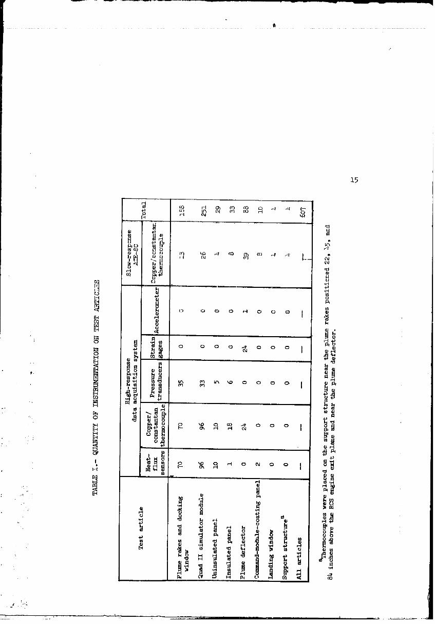
I QUANTITY OF INSTRUMENTATION ON TEST ARTICLES ...... 15
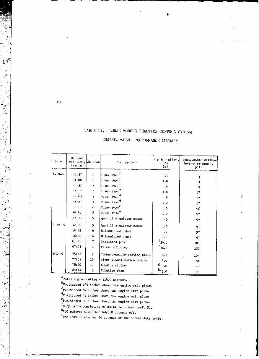
II LUNAR MODULE REACTION CONTROL SYSTEM ENGINE-PALLET
PERFORMANCE SOT_4ARY ................. 16
' FIGURES
Figure Page
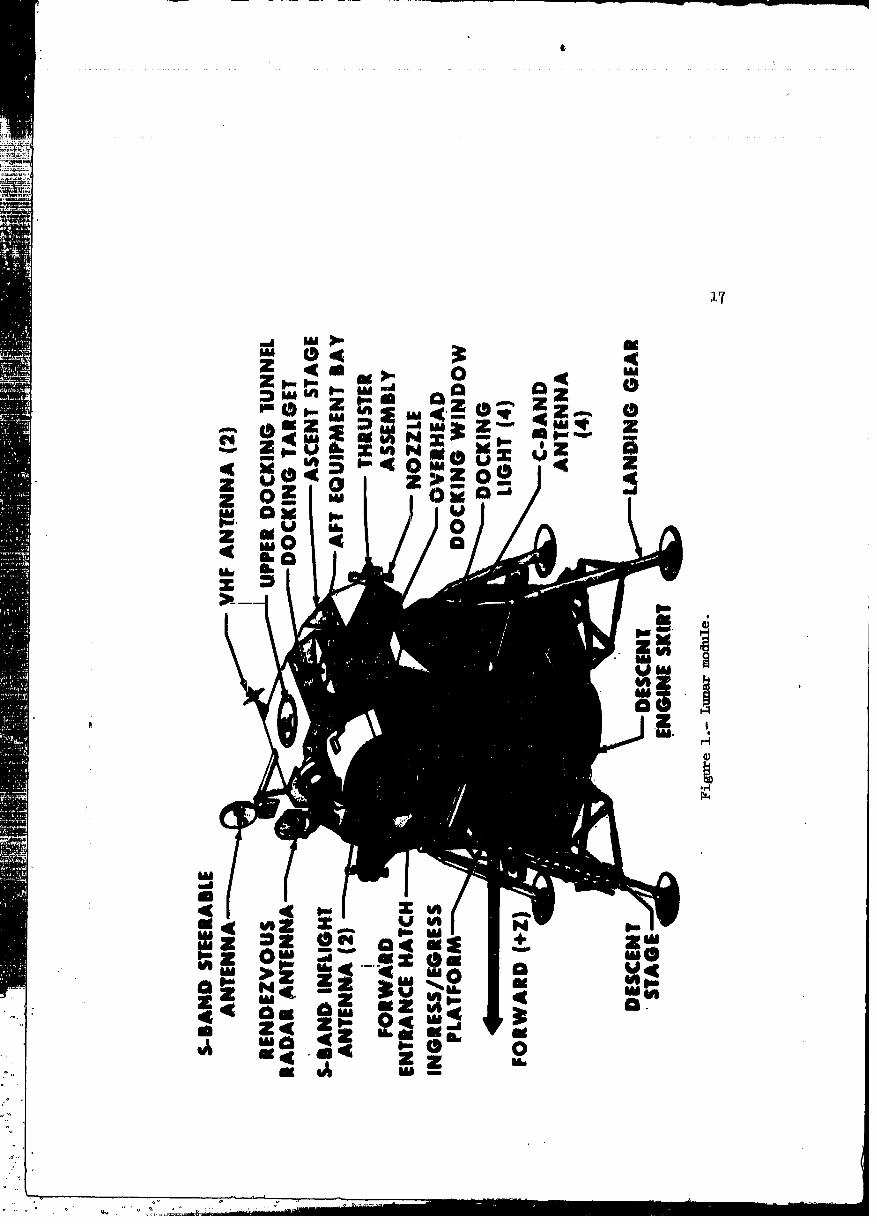
1 Lunar module .............................. _7
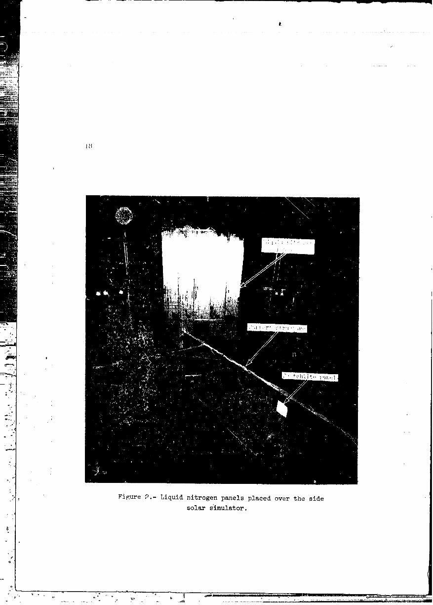
2 Liquid n_trogen panels placed over the sidesolar simulator ................... 18
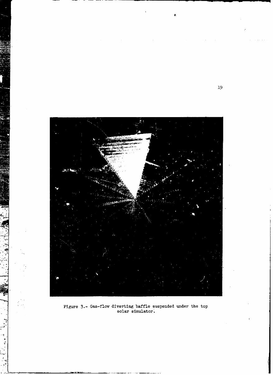
3 Gas-flow diverting baffle suspended under the top, solar simulator ....................... 19
I h Cross section, chamber A ................ 20
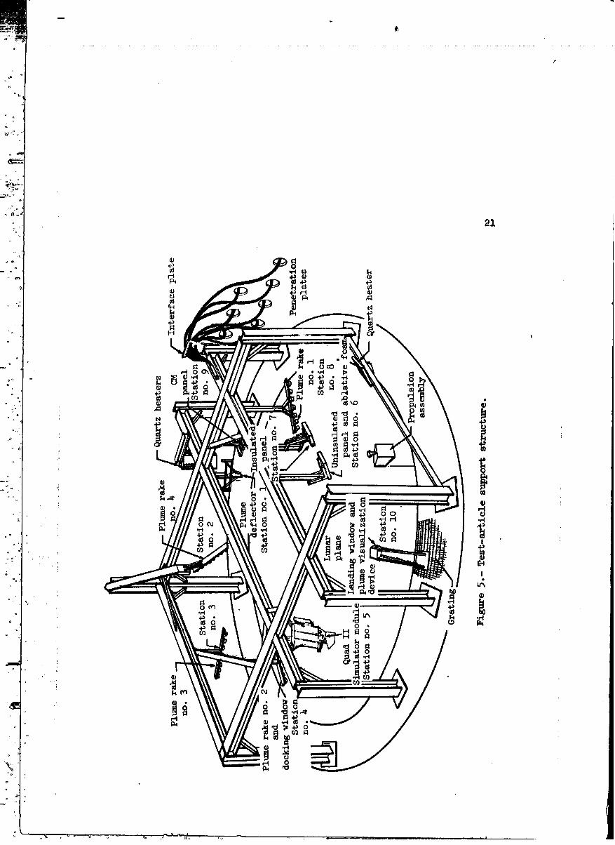
5 Test-article support structure ............. 21
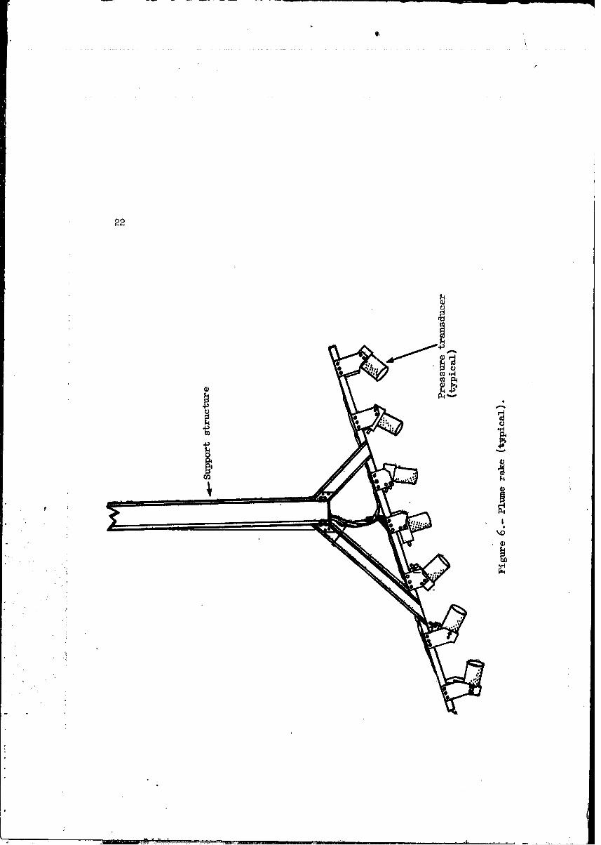
6 Plume rake (typical) .................. 22
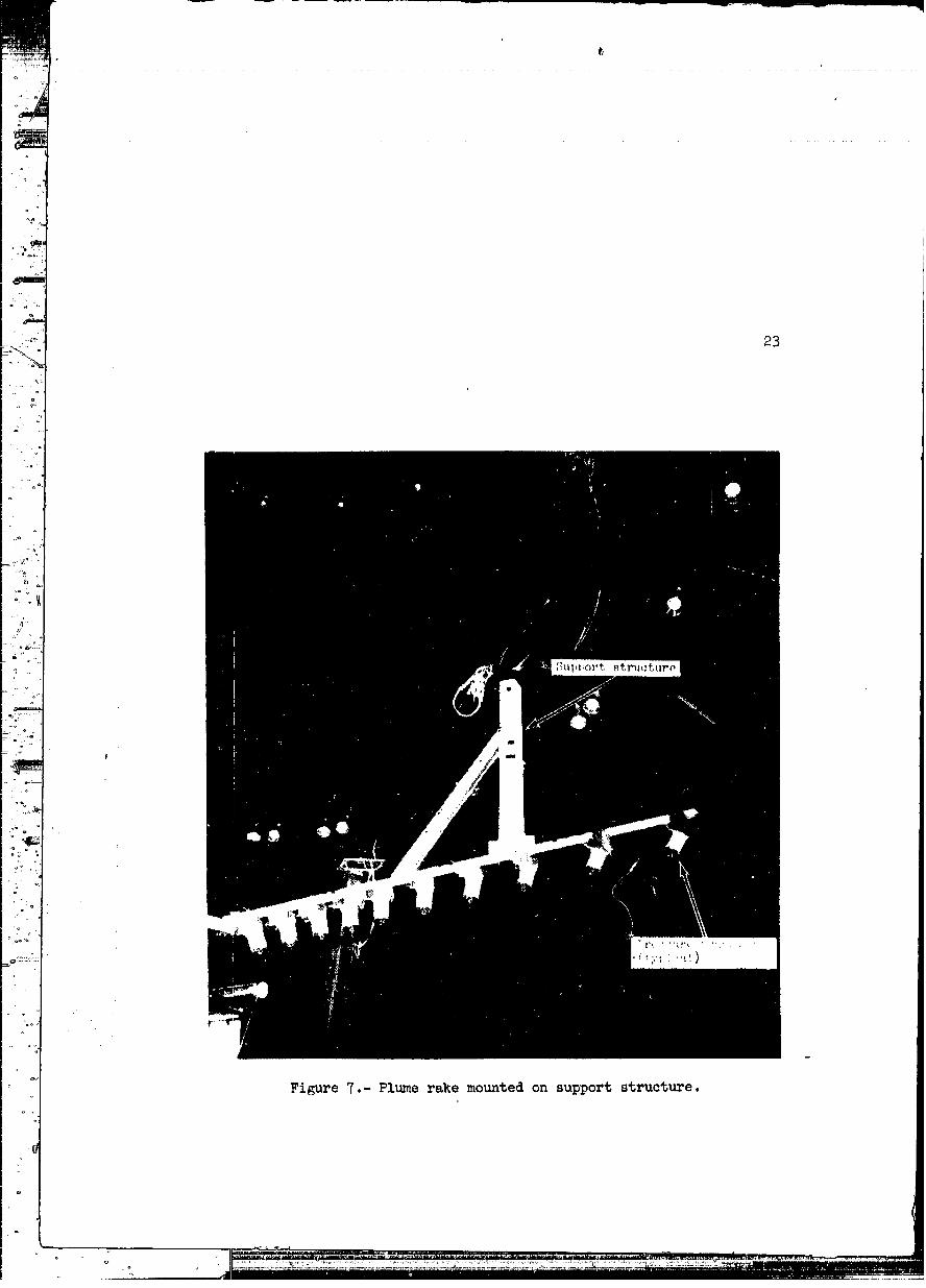
:, 7 Plume rake mounted on support structure ........ 23
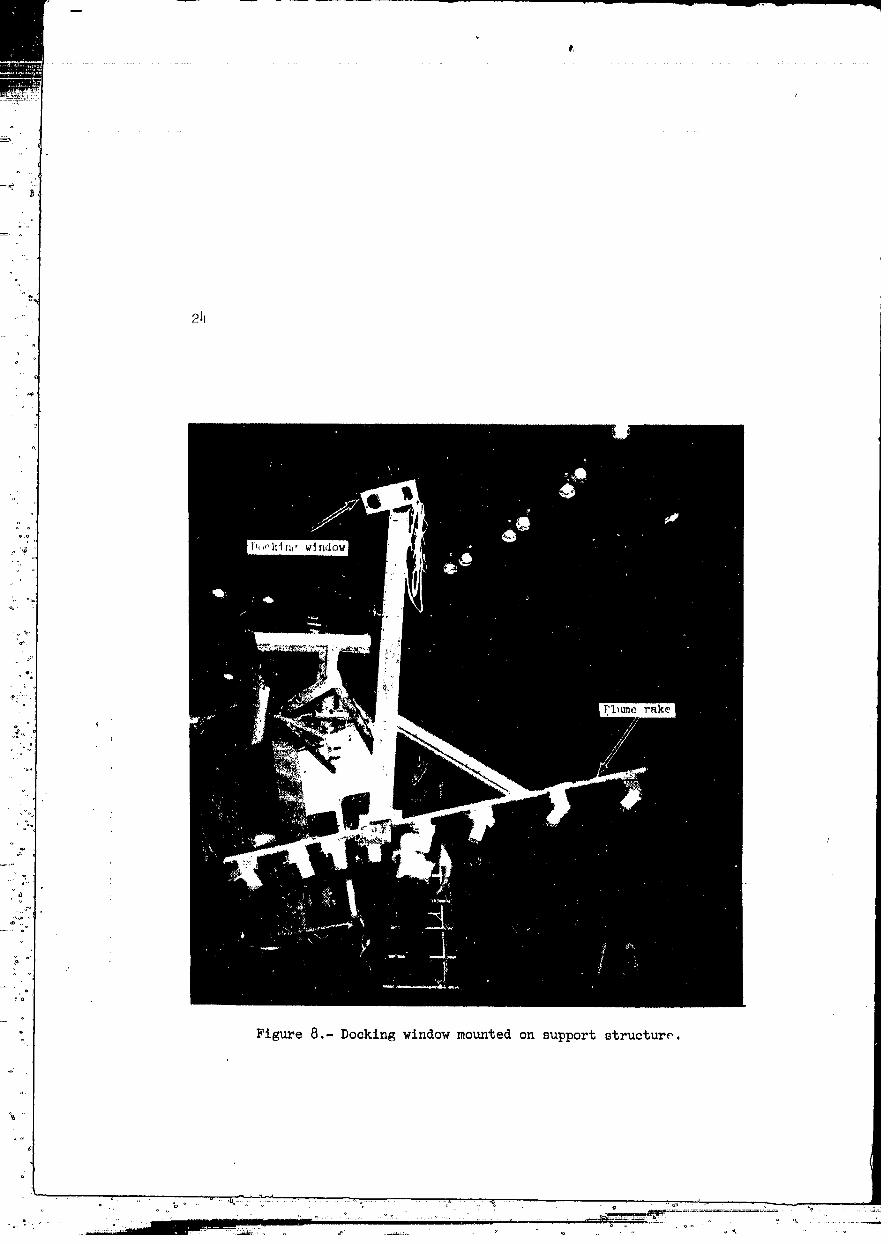
8 Docking window mounted on support structure ...... 2_
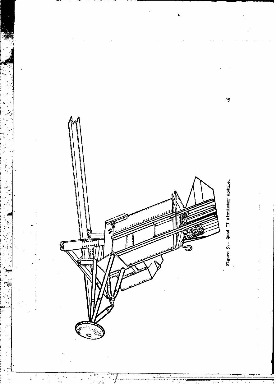
9 Quad II simulator module ................ 25
lO Quad II simulator module mounted on supportstructure ..................... 26
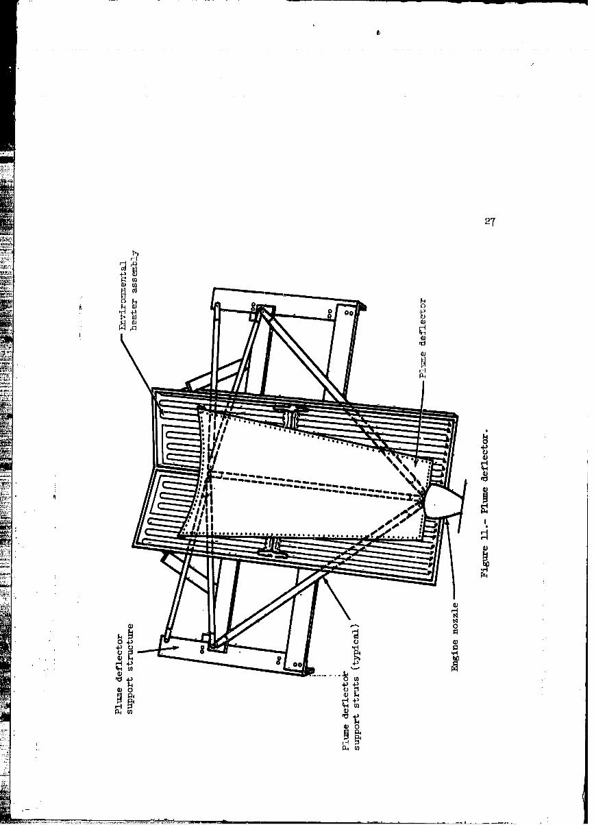
ll Plume deflector .................... 27
12 Plume deflector mounted on support structure ...... 28
13 Uninsulated panel and ablative foam .......... 29
lh Command module coating test panel mounted onsupport structure .................. 30
v
_ure Page
15 Insulated panel mounted on support structure ...... 31
16 Landing window and plume visualization device ..... 32
17 Engine pallet, exterior .............. . . 33
18 Engine pallet, interior ................ 34
19 Schematic diagram of the reaction control system
ensine-pallet propellant and pressurant systems • . • 35
20 Engine-firing console ................. 36
21 Data acquis,tion system ................ 37
22 Data acquisition system data flow ........... 38
23 Acceptance Checkout Equipment-Spacecraft, block
diagram ........................ 39
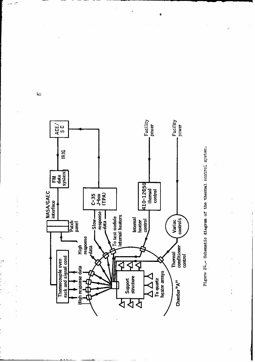
24 Schematic diagram of the thermal control system .... 40
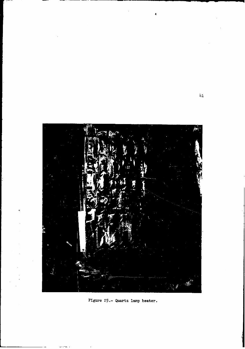
25 Quartz lamp heater ................... 41
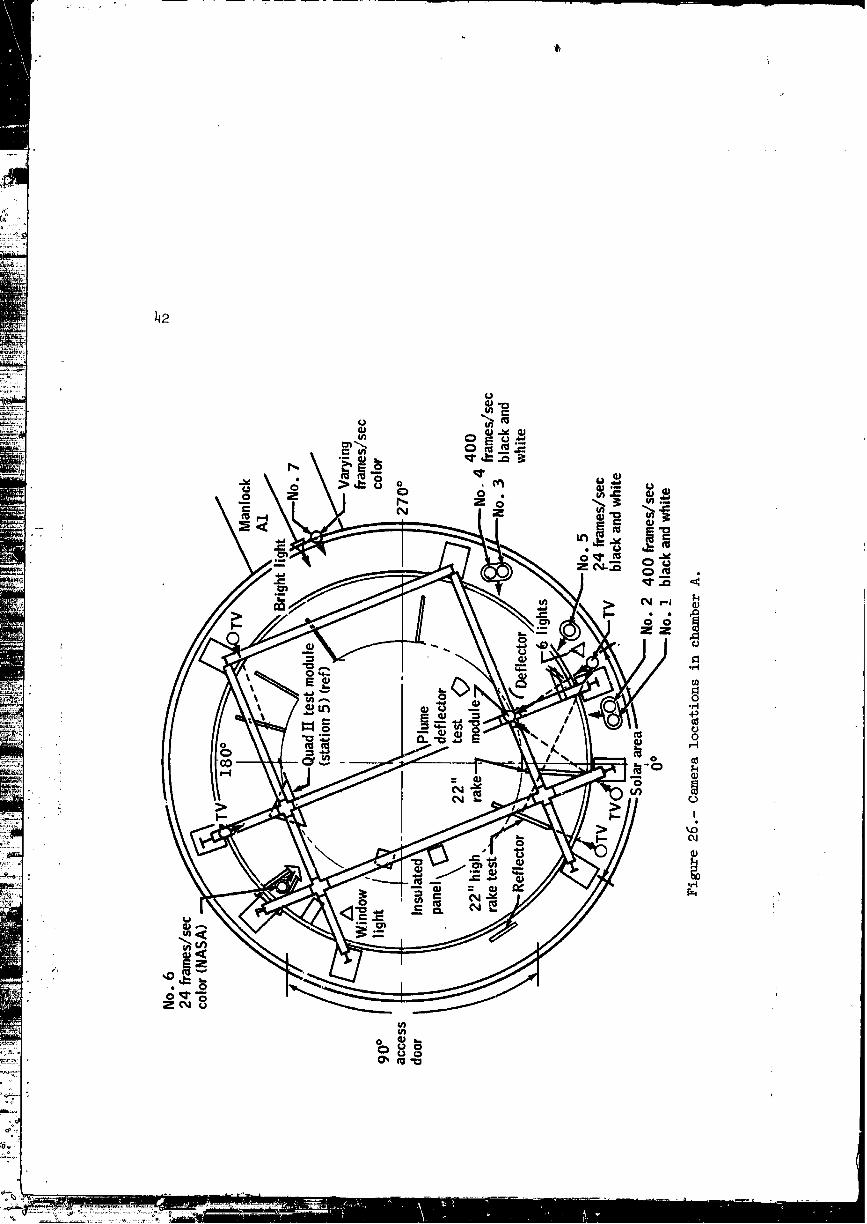
26 Camera locations in chamber A ............. 42
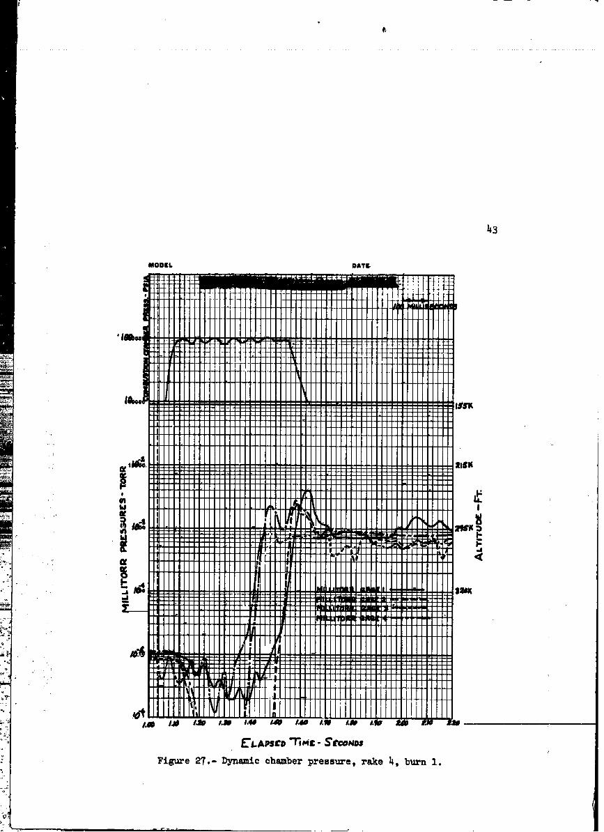
27 Dynamic chamber pressure, rake 4, burn 1 ........ 43
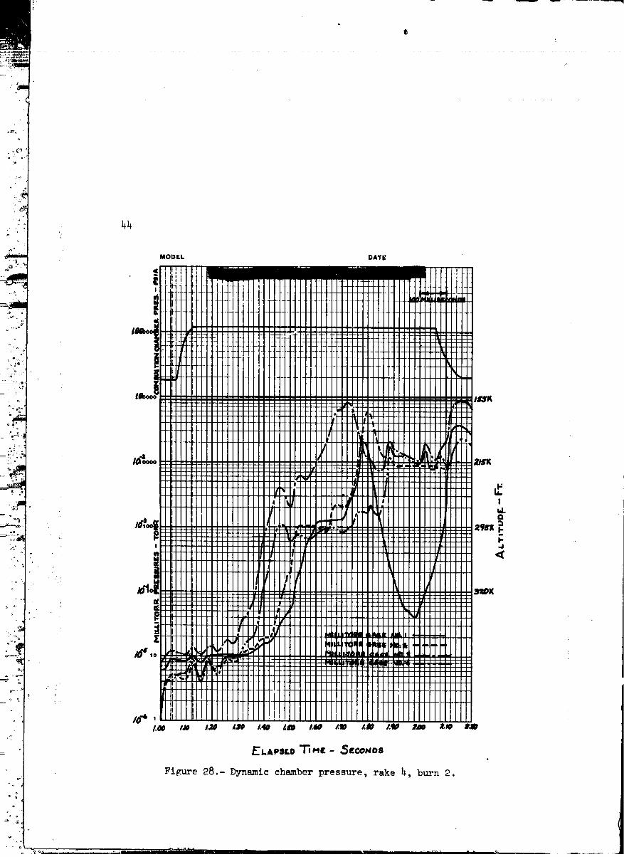
28 Dynamic chamber pressure, rake 4, burn 2 ........ 44
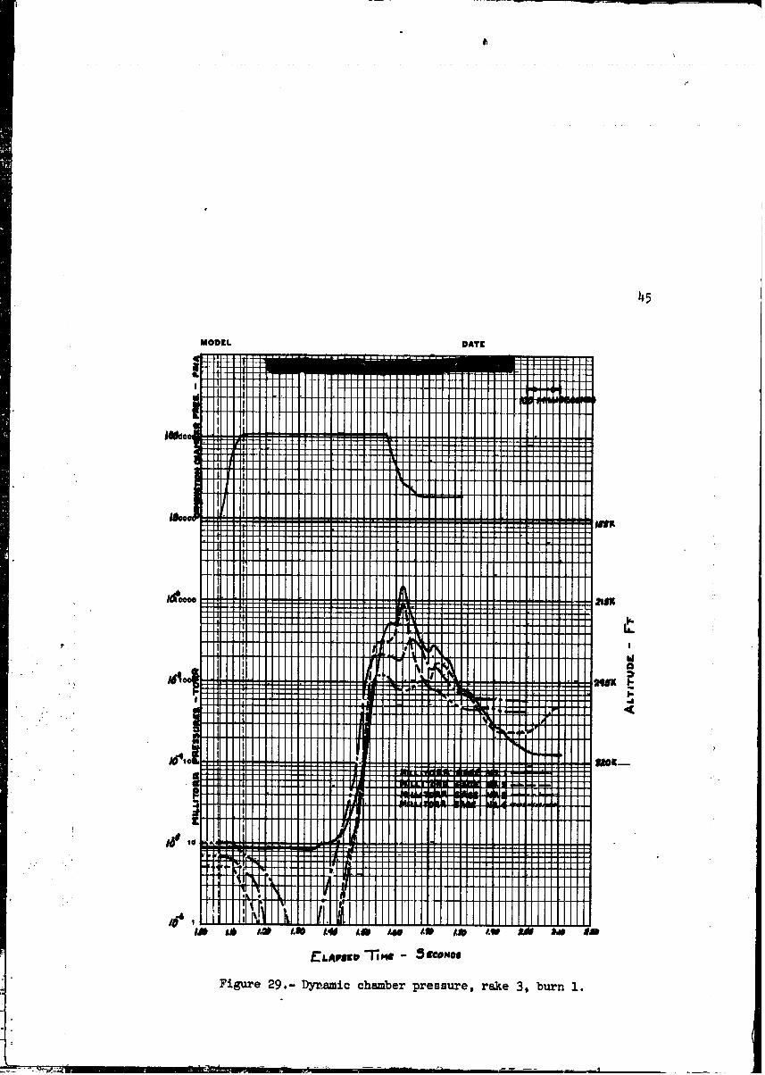
29 Dynamic chamber pressure, rake 3, burn 1 ........ 45
30 Dynamic chamber pressure, rake 3, burn 2 . . . ..... 46
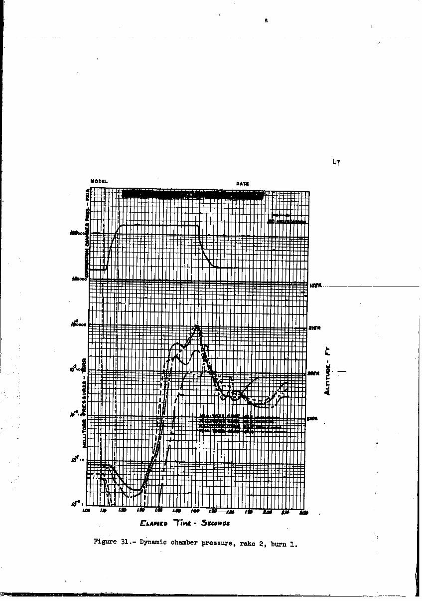
31 Dynamic chamber pressure, rake 2, burn 1 ........ 47
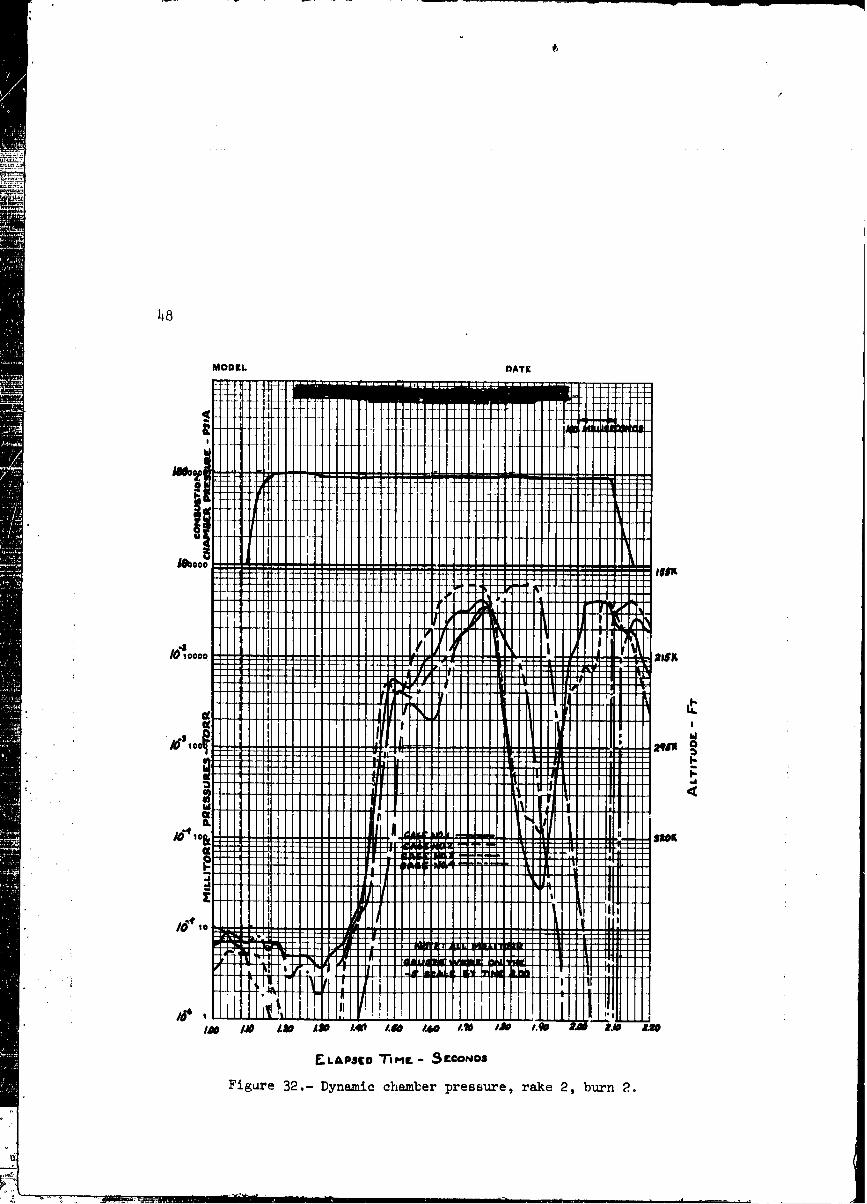
32 Dynamic chamber pressure, rake 2, burn 2 ..... 48• • •
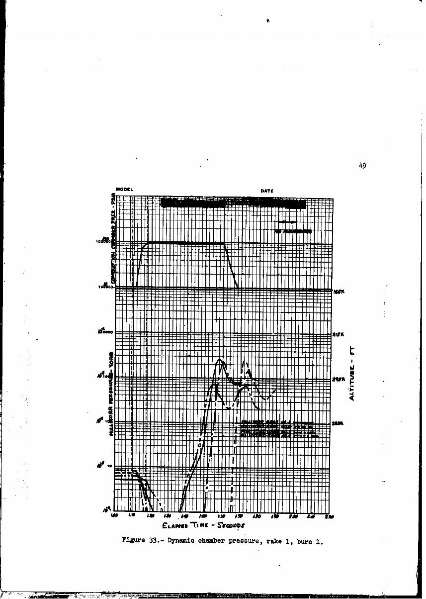
4933 Dynamic chamber pressure, rake i, burn I ........
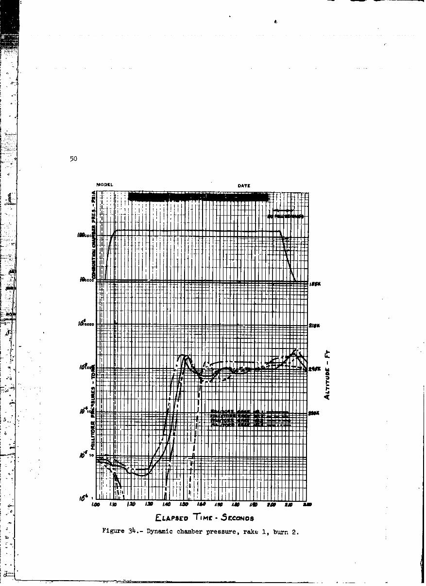
34 Dynamic chamber pressure, rake i, burn 2 ........ 50
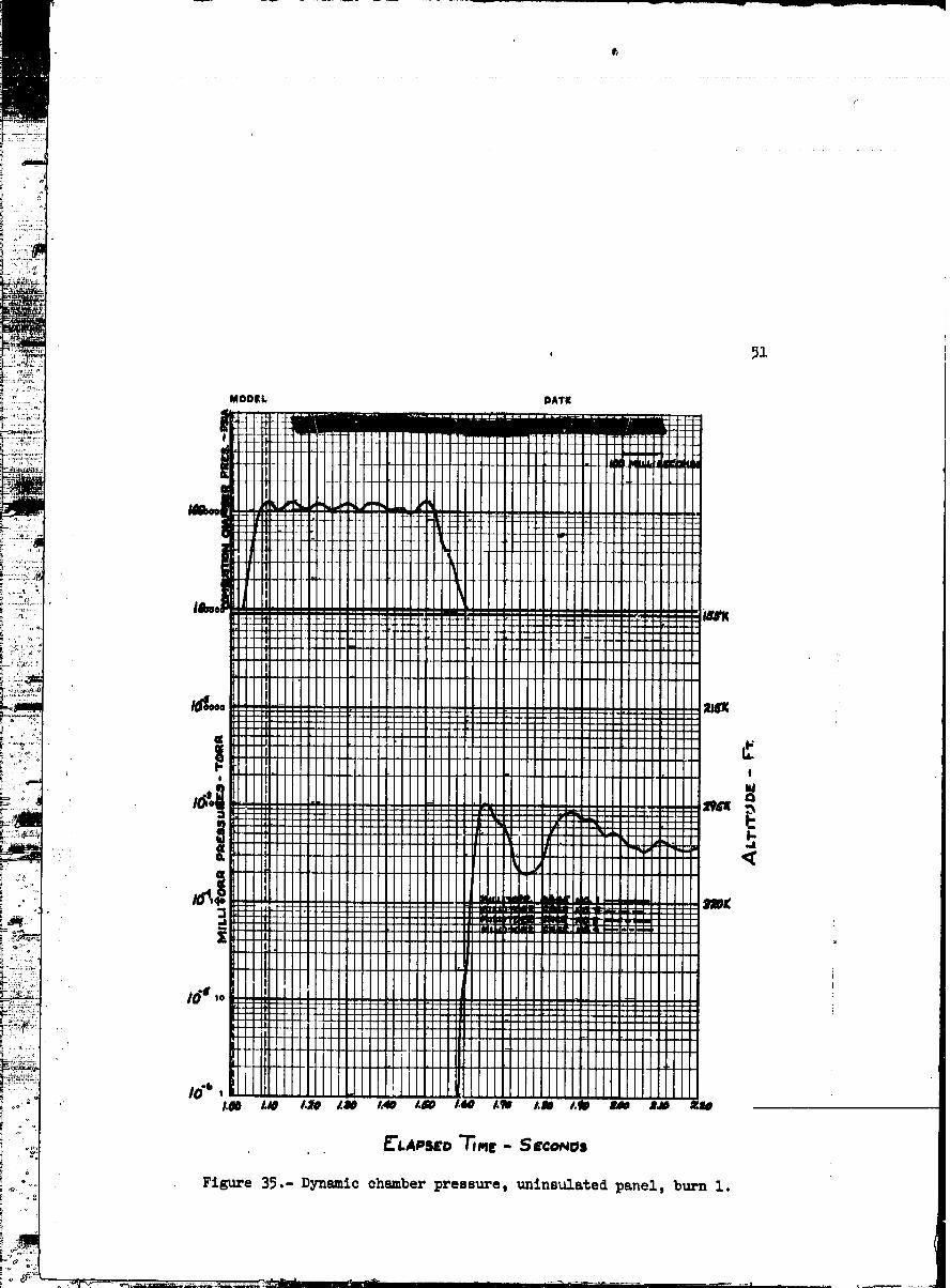
35 Dynamic chamber pressure, uninsulated panel,
burn 1 ........................ 51
00000001-TSA06
vi
Figure Page
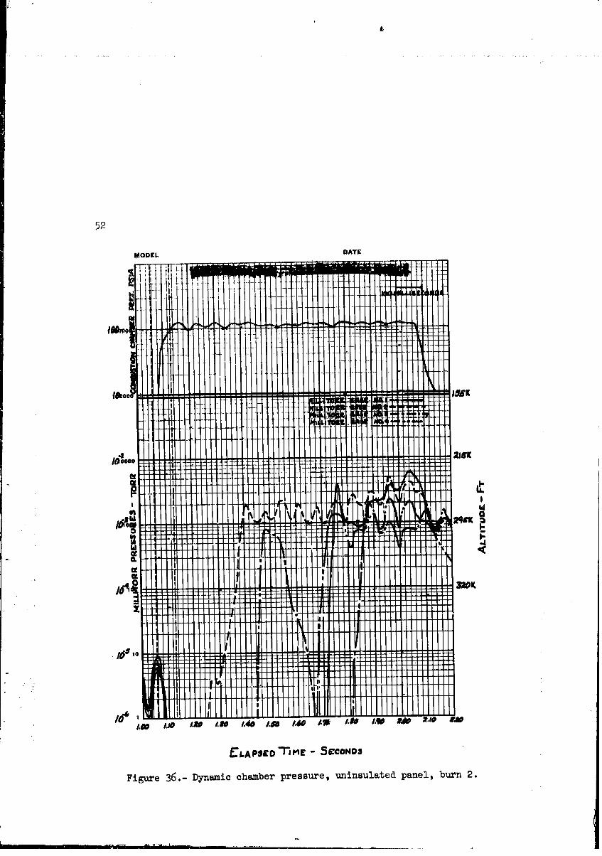
36 Dynamic chamber pressure, uninsulated panel,burn 2 . . . , ................. , . . 52
37 Dynamic chamber pressure, insulated panel burn ..... 53
38 Dynamic chamber prcssure, plume deflector burn ..... 5h
39 Dynamic chamber pressure, command module _oating
te:_t panel burn ................... 55
40 Dynamic chamber pressure, ablative foam burn ...... 56
41 Docking window, post-test ............... 57
42 Plume deflector, post-test .............. 58
43 Support-structure insulation damage .....--. ...... 59
44 Ablative foam, post-test ................ 60
45 Insulated panel, post-test ............... 6]
46 Landing window, post-test ................ 62
47 Scotchlite panel .................... 63
o., .% _ "_..:[_',._'._ llVlliililiiI .......... IIIIIIII IIIIII Ii
O0000001-TSA07
rl _I ,LUNAR MODULE [_EACTION CONTROL uYoT,I@I
ENGINE EXIIAUST PLUME EVALUATION TEST IN THE
SPACE ENV]]IOI_MENTSIMULATION LABORATORY
By the Space Envir(,nment Tost Division
INTRODUCTION
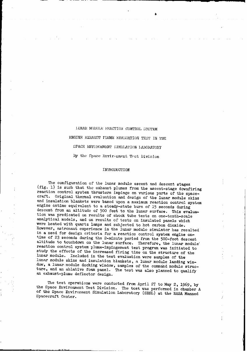
The configuration of the lunar module ascent and descent stages
(fig. l) is such that the exhaust plumes from the ascent-stage downfiring
reaction control system thrusters impinge on various parts of the space-craft. Original thermal evaluation and design of the lunar module skins
and insulation blankets were based upon a msximum reaction control system
engine ontime equivalent to a steady-state burn of 15 seconds duringdescent from an altitude of 500 feet to the lunar surface. This evalua-
tion was predicated on results of shock tube tests on one-tenth-scaleanalytical models, and on results of tests on insulated panels which
were heated with quartz lamps and subjected to hot carbon dioxide.
However, astronaut experience in the lunar module simulator has resulted
.:. in a need for design criteria for a reactioz control system engine on-, time of 23 seconds during the 2-minute period from the 500-foot descent
altitude to touchdown on the lunar surface. Therefore, the lunar module'
reaction control system plume-impingement test program was initiated tostudy the effects of the increased firing time on the structure of the
lunar module. Included in the test evaluation were samples of the
lunar module skins and insulation blankets, a lunar module landing win-dow, a lunar,module docking window, samples of the comm/nd module struc-
ture, and an ablative foam panel. The test was also planned to qualifyan exhaust-plume deflector design.
The test operations were conducted from April 27 to May 2, 1969, by
the Space Environment Test Division. The test was performed in chamber Aof the Space Enviromnent Simulation Laboratory (SESL) at the NASA MannedSpacecraft Center.
00000001-TSA08
2
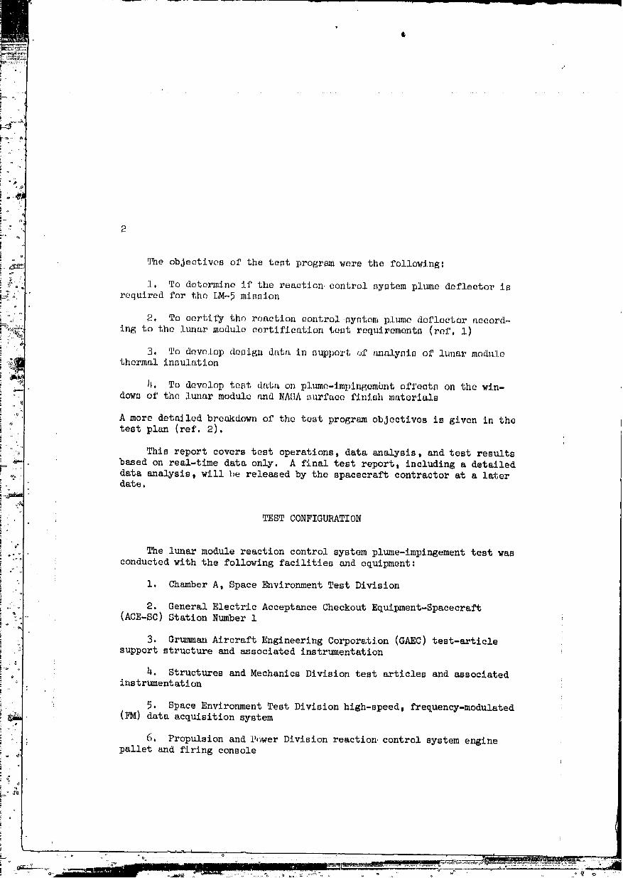
_e objectives of the test program were the following:
], To determine if the reactiGn control system plume deflector isrequired for the LM_5 mission
2. To certify the reaction control system plume deflector accord-
ing to the lunar module certification test requirements (ref. i)
3. To develop design data in support of _alysis of luuar modulethermal insulation
)_. To develop test data on plume-impingombnt effects on the win-dows of the lunar module and NASA surface finish materials
A more detailed breakdown of the test program objectives is given in thetest plan (ref. 2).
This report covers test operations, data analysis, and test results
based on real-time data only. A final test report, including a detaileddata analysis, will be released by the spacecraft contractor at a laterdate.
TEST CONFIGURATION
The lunar module reaction control system plume-impingement test wasconducted with the following facilities and equipment:
1. Chamber A, Space Environment Test Division
2. General Electric Acceptance Checkout Equipment-Spacecraft(ACE-SC) Station Number 1
3. Grumman Aircraft Engineering Corporation (GAEC) test-articlesupport structure and associated instrumentation
_. Structures and Mechanics Division test articles and associatedinstrumentation
5. Space Environment Test Division high-speed, frequency-modulated(FM) data acquisition system
; 6. Propulsion and Power Division reaction control system enginepallet and firing console
L ...... *' L• _ll
00000001 -TSA09
¢,
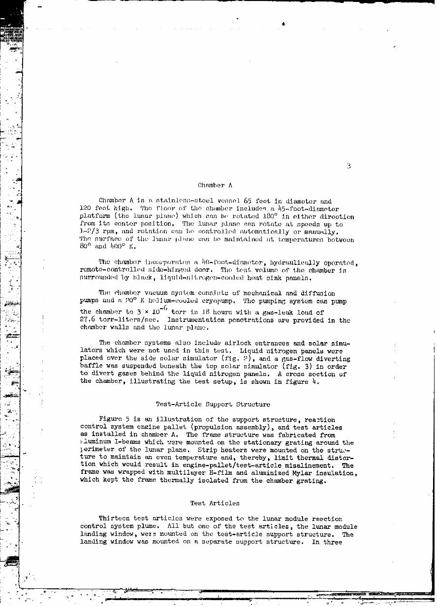
Chamber A
Chamber A is a nt_,inlo_f_tool vessel 65 foot in diameter and
120 foot high. The f]oc_rof the ehl_nbcr include_ t__5-foot-di0_eter
platform (the lunar planf_) which can b,,rott_tod 180° in olthor direction
from its center position. The lunar }dane can rotate at speeds up to
i_2/3 rpm) s,nd rotation san 'l-mcontro].].odautomatically or manually.The stiff,co of the lumbar ],]_,nocan be maJntrdnod at temperatures between80 ° and })00 ° K.
_[_qo(;h_nbor :Iz)e()r_)or_,,t(m I,,)iO-f(>ot-di_1_)_{_to_,, hydra1_lie_lly operated,remote-controlled _ide-hlnt_,_,ddoor. The t_,st vol_no of the chamber is
nurro_ndod by '|)] at;k, ],:Iquiil-)11'l,r<.>g(,)-)-(;ool(._dhe_t sink panels.
The eh_,mber w_cuum syl)t,c.mconsJ_)ts of mechanictL1 and di_'_k_sion
pumps and a 90° K ho]_um-(:ool_d cryoptm,p. The pumping system can pump
the chamber to 3 × lO"6 torr in ]8 hours with a gas-]e_k lo_d of
27.6 tort-liters/see. Instrt_,,entationpenetrations are provided in thechamber walls and the lunar i)](u_e.
The chamber systems also include airlock entrances and solar simu-
lators which were not used in this test. Liquid nitrogen panels wereplaced over the side solar simulator (fig. 2), and a gas-flow diverting
baffle was suspended beneath the top solar simulator (fig. 3) in order
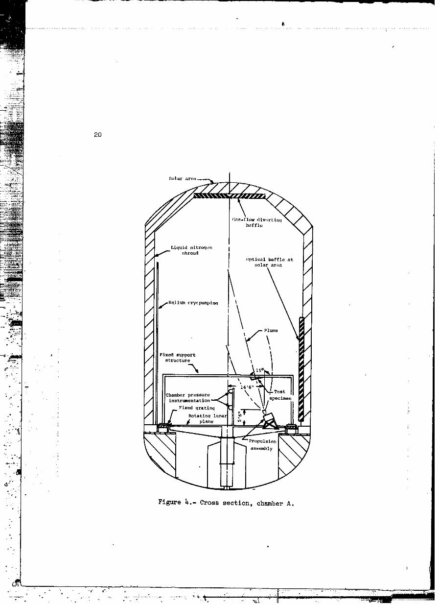
to divert gases behind the liquid nitrogen panels. A cross section ofthe chamber, illustrating the test setup, is shown in figure h.
Test-Article Support Structure
Figure 5 is an illu._tration of the support structure, reactioncontrol system engine pallet (propulsion assembly), and test articlesas installed in chamoer A. The frame structure was fabricated from
_luminum I-beams which _.'eremo_mted on the stationary grating around the_erimeter of the lunar plane. Strip heaters were mounted on the struc-
ture to maintain an even temperature and, thereby, limit thermal distor-tion which would result in engine-pallet/test-artlcle misalinement. The
frame was wrapped with multilayer H-film and aluminized Mylar insulation,
which kept the frame thermally isolated from the chamber grating,
Test Articles
Thirteen test articles were exposed to the lunar module resction
control system plume. All but one of the test articles, the lunar module
landing window, wez_ mounted on the test-smticle support structure. Thelanding window was mounted on a separate support structure. In three
O0000001-TSAI 0
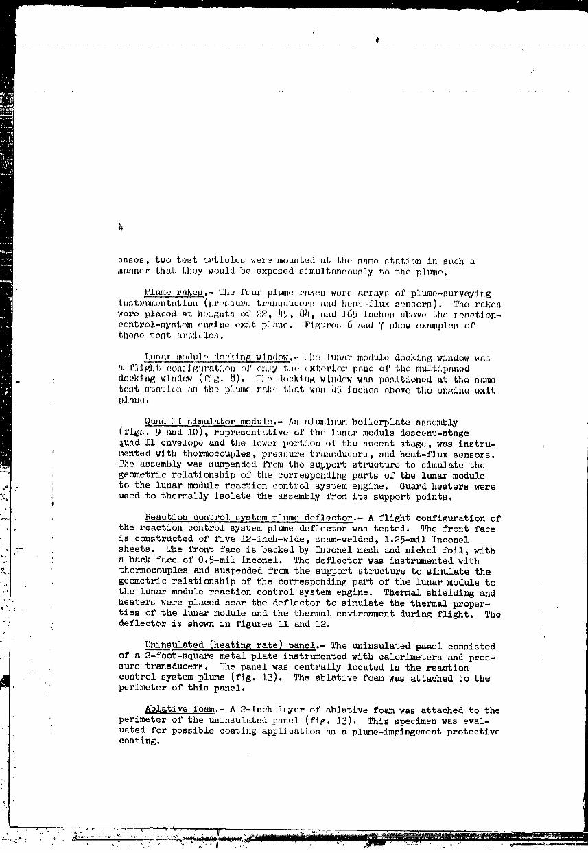
eases, two test articles were mounted at the same station in such m
manner that they would be exposed slmultanooucly to the plume,
Plume rsken,_ The four plume rrLkonwere array_ of plumo_survoy_ngi,lstrumentation (pressure. tranfJdueerf_and hoat_flux sensors), The rakeswere platted at huightf_ of 22, )15,_)i, and 165 inches above the roactio_-
contro]-syntom rmg_ne oxlt piano. F:l.guro_6 and,7 show ex1_mples ofthose test a_'tlel(:;_.
,!Lun_jt3__mod_U_]odockj_n_ggWindow,- 'J'hu]unnr modul(_ do(:!klngwindow wt_s
a f'li_hl,con£1HuratJ.on of on;ly the (,xtorior pnne oi}the multip_med
_ sloe,king window (.r:Ig,8), Th(,_ dock'Lnfg window was ponl.tioned at the same
test stati_,n rm tim p]_n(: r_:: theftwas h5 inches above the engine exit'0.1.an_,
.._uad]I 0im.u:1,_;tormodule,- An t_l_llinumboilerplate assembly
(figs. 9 and lO), representatiw., of the ltm_r module descent-stage_uad II envelope _nd the lower portion of the ascent stage, was instru-
laented with thermocouples, pressure transducers, and heat-flux sensors•
The assembly was suspended from the support structure to simulate thegeometric relationship of the corresponding parts of the lunar module
to the lunar module reaction control system engine Guard heaters were
., used to thermally isolate the assembly from its support points,
Reaction control s_stem plume deflector.- A flight configuration ofthe reaction control system plume deflector was tested. The front face
is constructed of five 12-1rich-wide, seam-welded, 1.25-mil Inconel
-- sheets. The front face is backed by Inconel mesh and nickel foil, with. a back face of 0.5-mil Inconel. The deflector was instrumented with
thermocouples and suspended from the support structure to simulate the
geometric relationship of the corresponding part of the lunar module to
the lunar module reaction control system engine. Thermal shielding and
• heaters were placed near the deflector to simulate the thermal proper-
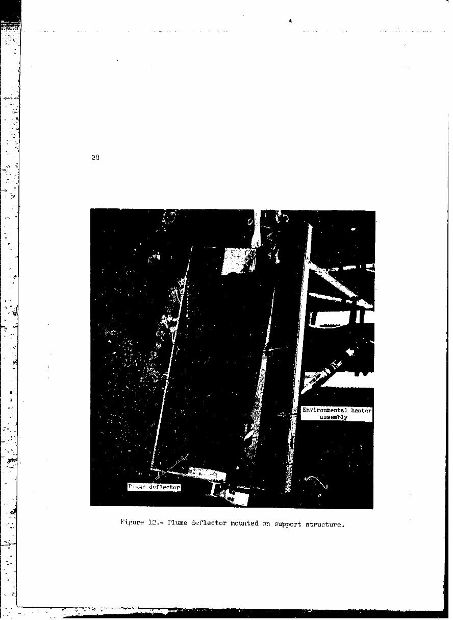
ties of the lunar module and the thermal environment during flight. Thedeflector is shown in figures ll and 12.
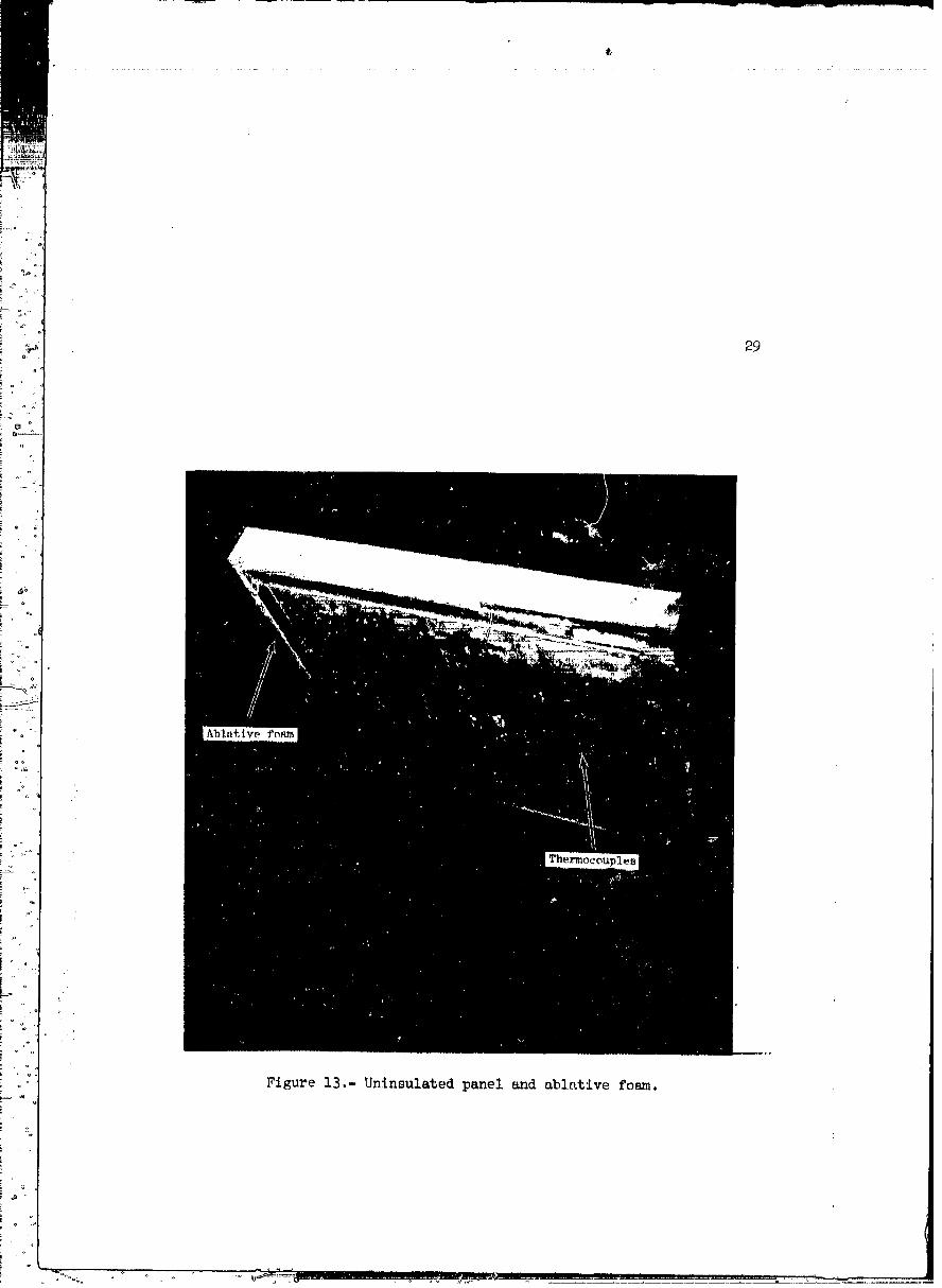
Uninsulated (heating rate) panel.- The uninsulated panel consisted
of a 2-foot-squa_e metal plate instrumented with calorimeters and pres-.. sure transducers. The panel was centrally located in the reaction
control system plume (fig. 1B). The ablative foam was attached to the
perimeter of this panel.
Ablative foam.- A 2-inch layer of ablative foam was attached to the
perimeter of the unlnsulated panel (fig. 13). This specimen was eval-
uated for possible coating application as a plume-implngement protectivecoating.
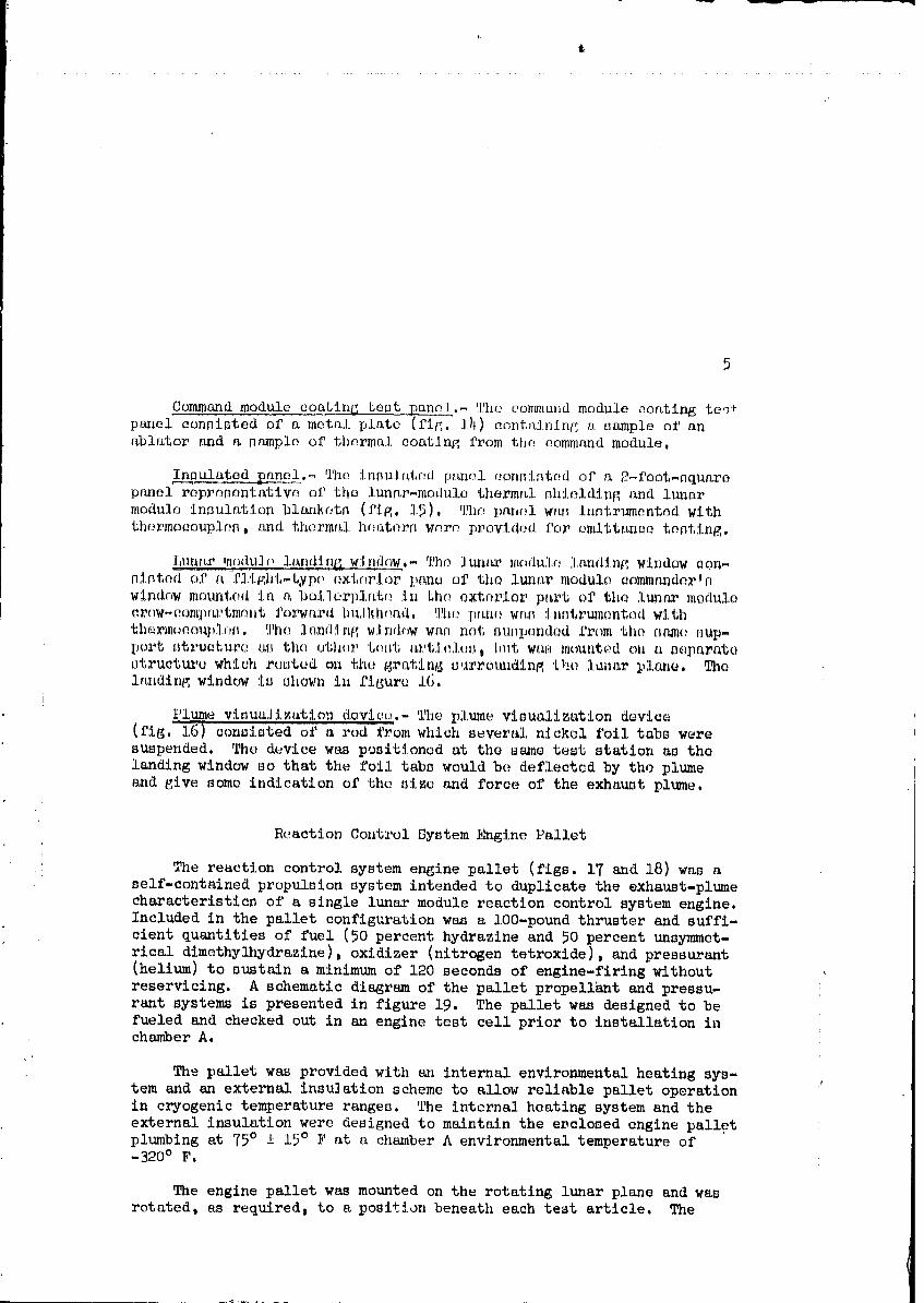
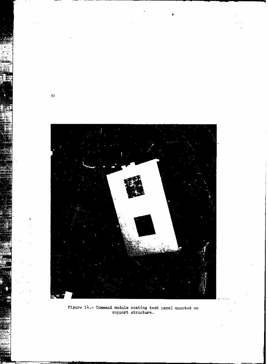
Command module coating teat panel._ The co_imld module seating te,?'_
p_el consisted of a metal plate (fig. i)I)eontainlng a sample of anablator and a sample of thermal coating from the command module.
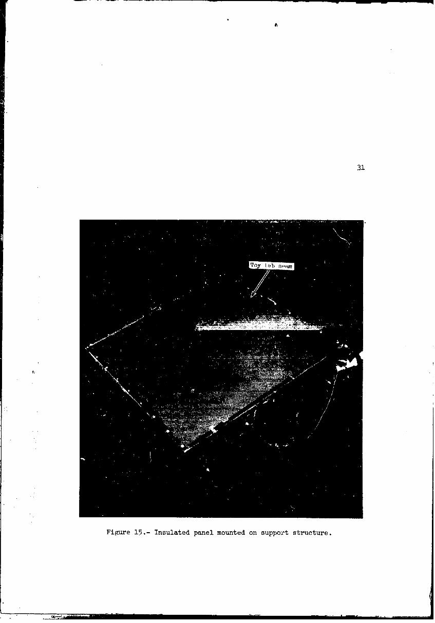
Insulated _panel.- The _nsu]1_tod p_ol c_,onsintedof a 2_foot-squaro
panel representative of the lun_r-modulo thermal shielding t_ndlunarmodulo insulation blank_ts (f_g. 15). The panel was instrumentnd with
thermo_ouplen, lindthermal hnators wnro pl_ovided for omitt_nee testing.
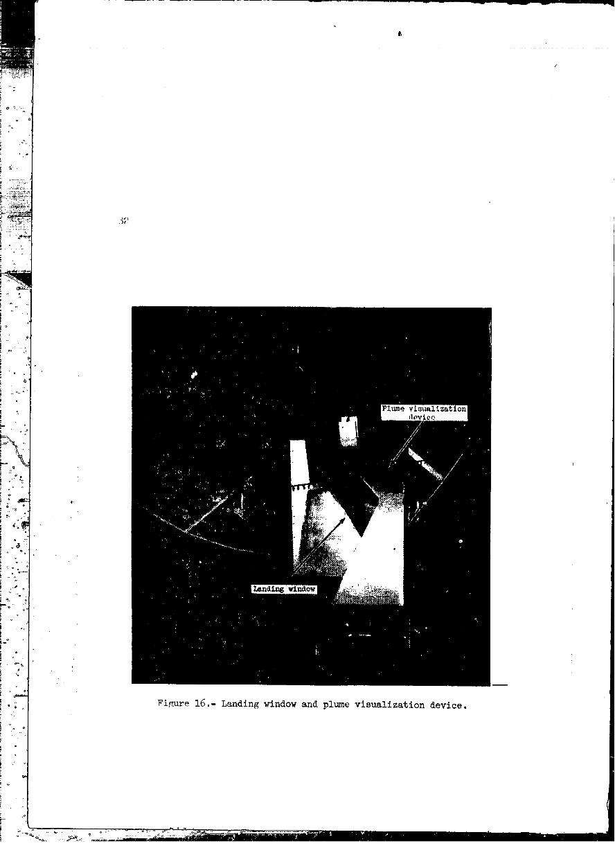
Lunt_ moduJo landin_ w:l!!dow.-']'he]t_m? m_,dul_,l[_nding window con-nlnted of a-fl{_ht-typ_ oxtorlor l,_no of the luaar modulo commandertn
windc,w mounted In a bo_Ior]?lato in Lho oxtorlor pf_rt of the l_n_ modulocr(_w-eomprLtltmontforward |)1_]lch(_n,d.']!hepans was inntrtunonted w;lth
th(_rmoc.mu],.l,_.!l'holnnd:In{;window waf_ not s_pondod from the [_am_ sup-
port _tructurc a_ the uti,or 'l,et_t _L_'t;l.O.lu_.hut wa_ mount(_,don a separatestructtu,o which r[mtud on the 6r_tln6 uurro_mdln_ the isnar plane. Thelandln_ window Is shown in figure 16.
1'lume visualization device,s.-The plt_e visualization device(fig. l_) consisted of a rod i'romwhich seversl nickel foil tabs were
suspended. The d_vice was positioned at the same test station as the
landing window so that the foil tabs would be deflected by the plume
8_ndgive some indication of the size and force of the exhaust plume.
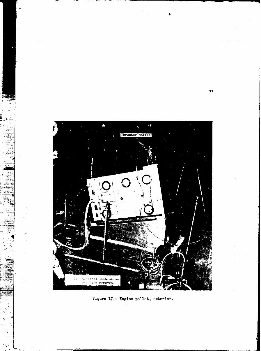
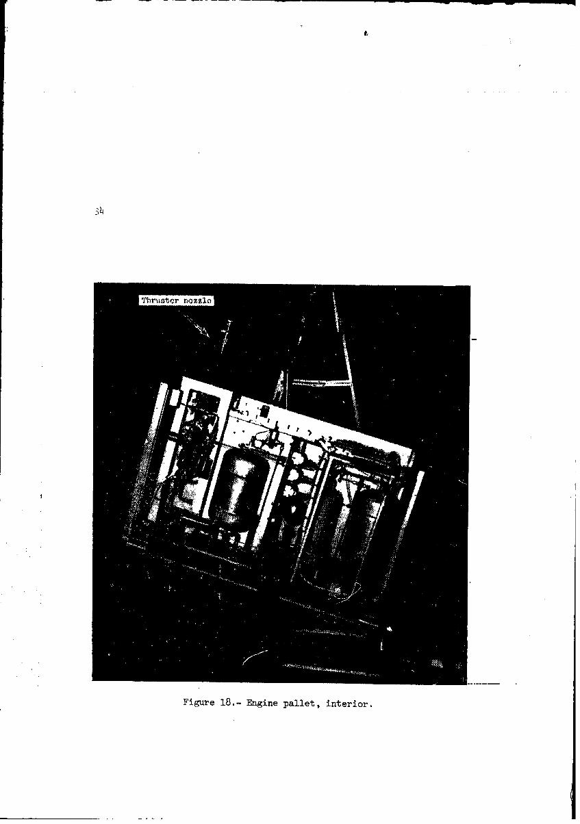
Reaction Control System Engine Pallet
.' The reaction control system engine pallet (figs. 17 and 18) was a
self-contained propulsion system intended to duplicate the exhaust-plumecharacteristics of a single lunar module reaction control system engine.
Included in the pallet configuration was a lO0-pound thruster and suffi-
cient quantities of fuel (50 percent hydrazine and 50 percent unsymmet-rical dimethylhydrazlne), oxidizer (nitrogen tetroxlde), and pressu__ant(helium) to sustain a minimum of 120 seconds of engine-flrlng without
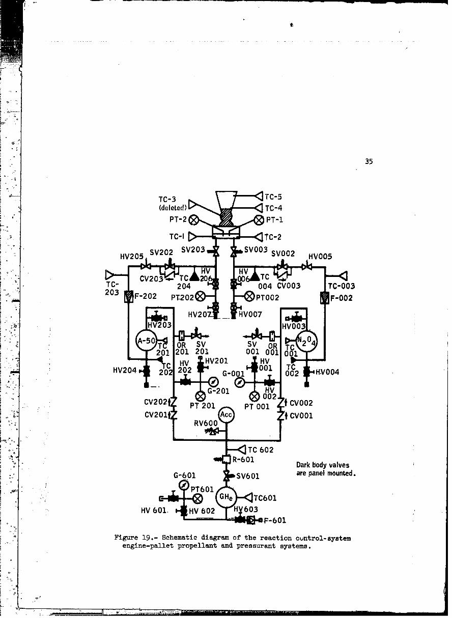
reservicing. A schematic diagram of the pallet propellant and pressu-rant systems is presented in figure 19. The pallet was designed to be
fueled and checked out in an engine test cell prior to installation Anchamber A.
The.pallet was provided with an internal environmental heating sys-
tem and an external insulation scheme to allow reliable pallet operationin cryogenic temperature ranges, The internal heating system and the
external insulation were designed to maintain the eDclosed engine palletplumbing at 75° ± 15° F at a chamber A environmental temperature of-320 ° F.
The engine pallet was mounted on the rotating lunar plane and wasrotated, as required, to a position beneath each test article. The
00000001-TSA12
6
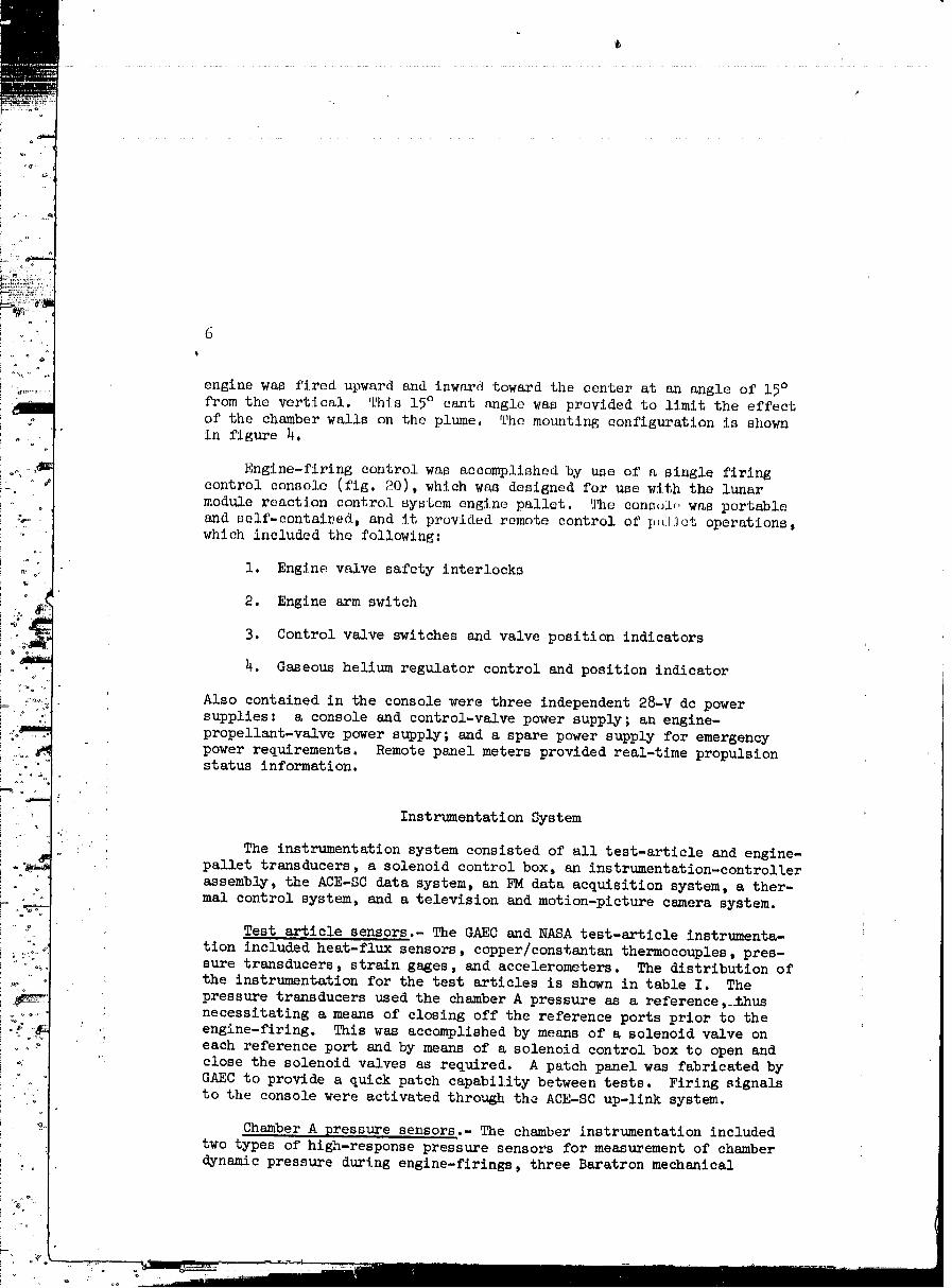
engine was fired upward and inward toward the center at an angle of 15°from the vertical. This 15° cant angle was provided to limit the effect
of the chamber walls on the plume. The mounting configuration is shown
in figure 4.
Engine-firing control was accomplished by use of a single firing
control console (fig. 20), which was designed for use with the lunar
module reaction control system engine pallet. The consolr, was portableand self-contai:!ed, and it provided remote control of I"']lot operations,which included the following:
1. Engine valve safety interlocks
2. Engine arm switch
3. Control valve switches and valve position indicators
4. Gaseous helium regulator control and position indicator
Also contained in the console were three independent 28-V dc power
supplies: a console and control-valve power supply ; an engine-
propellant-valve power supply; and a spare power supply for emergencypower requirements. Remote panel meters provided real-time propulsionstatus information.
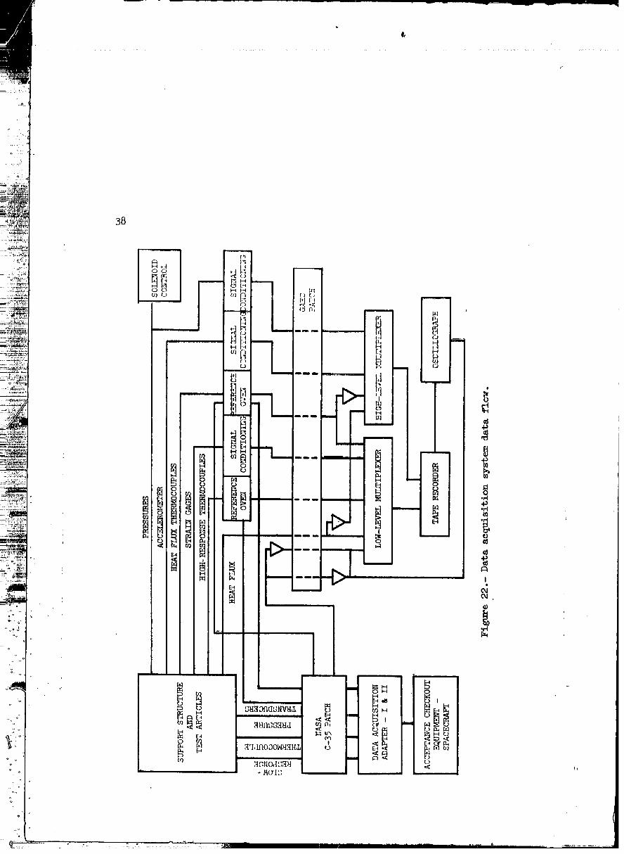
Instrumentation System
_ The instrumentation system consisted of all test-article and engine-
pallet transducers, a solenoid control box, an instrumentation-controller
assembly, the ACE-SC data system, an FM data acquisition system, a ther-
mal control system, and a television and motion-picture camera system.
Test article sensors.- The GAEC and NASA test-article instrumenta-
tion included heat-flux sensors, copper/constantan thermocouples, pres-sure transducers, strain gages, and accelerometers. The distribution ofthe instrumentation for the test articles is shown in table I. The
pressure transducers used the chamber A pressure as a reference, _hus
necessitating a means of closing off the reference ports prior to theengine-firing. This was accomplished by means of a solenoid valve oneach reference port and by means of a solenoid control box to open and
close the solenoid valves as required. A patch panel was fabricated byGAEC to provide a quick patch capability between tests. Firing signals
to the console were activated through the ACE-SC up-llnk system.
Chamber A pressure sensors .- The chamber instrumentation includedtwo types of high-response pressure sensors for measurement of chamber
_ynamic pressure during englne-firlngs, three Baratron mechanical
00000001-TSB01
' TEST OI'EI{ATION[I
t
On April 27, 1969, the rr:act:l()n c.ont.:r'(,J iiylvl,,qil i,iigl.li,, pl,.I.l,,l, w,l.lltransported from the Thermo(.'iitml:i cti,.l [l'_ltl, At'(,l_ t,o I,h,; l ll,l:ll, w l.l,ti lt,iil,hl_i'l ,/,t,d
safety procedures in force, 'i%_-_ 1,;_];t_'t; wtl,ll llliiLtl, IJl!ll ti.lllt tl..tllil,_l Ill
cliamber A in accordance with llpprovud In l,i:rJ'tl.i!l;(JimLr,i] lJr,f!um,,lil,l,i',,vl-
slons. Pumpdown was initiated _t (iO;!Ohourli ,,ilAl)rlJ ;_lJ,]Uf,9.
8
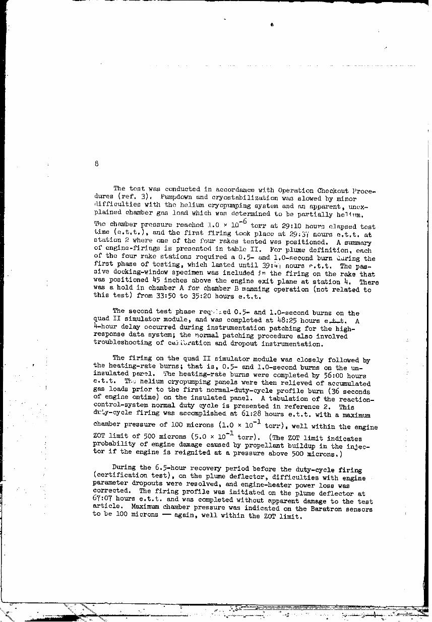
The test was conducted in accordance with Operation Checkout Proce-
dures (ref. 3). Pumpdown and eryostabilization was slowed by minor
_lifficulties with the helium cryopumping system and an apparent, unex-
plained chamber gas load which was determined to be partially he1_m.
The chamber pressure reaehod 1.0 _ l0-6 torr at 29:10 hou_ elapsed test
time (e.t.t.), and the first firing took place at 29_3_inours e.t.t, at
station 2 where one of the four rakes tested wss positioned. A summary
of engine-firings is presented in table II. For plume definition, eachof the four rake stations required a 0.5- and 1.0-second burn aarlng the
first phase of testing, which lasted until 39:4] nours _.t.t. The pas-sive docking-window specimen was included ._ the firing on the rake that
was positioned 45 inches above the engine exit plane at station 4. There
was a hold in chamber A for chamber B manning operation (not related tothis test) from 33:50 to 35:20 hours e.t.t.
The second test phase req,_ed 0.5- and 1.0-second burns on thequad II simulator module, and was completed at 48:25 hours e._.t. A
h-hour delay occurred during instrumentation patching for the high-
response data system; the normal patching procedure also involvedtroubleshooting of c_ilb_ation and dropout instrumentation.
The firing on the quad II simulator module was closely followed by
, the heating-rate burns; that is, 0.5- and 1.0-second burns on the un-
insulated panel. '_aeheating-rate burns were completed by 56:00 hours
e.t.t. T%,_ helium cryopumplng panels were then relieved of accumulated
! gas loads prior to the first normal-duty-cycle profile burn (36 seconds
of engine ontime) on the insulated panel. A tabulation of the reaction-
, control-system normal duty cycle is presented in reference 2. This
duty-cycle firing was accomplished at 61:28 hours e.t.t, with a maximum
chamber pressure of 100 microns (1.0 x l0-1 torr), well within the engine
ZOT limit of 500 microns (5.0 × l0-1 tort). (The ZOT limit indicates
probability of engine damage caused by propellant buildup in the injec-tor if the engine is reignited at a pressure above 500 microns.)
During the 6.5-hour recovery period before the duty-cycle firing(eertificatiou test), on the plume deflector, difflcultie_ with engine
._ parameter dropouts were resolved, and engine-heater power loss was.. corrected. The firing profile was initiated on the plume deflector at
67:07 hours e.t.t, and was completed without s,pparent damage to the testarticle. Maximum chamber pressure was indicated on the Baratron sensorsto be 100 microns _ again, well within the Z0T limit.
00000001-TSB03
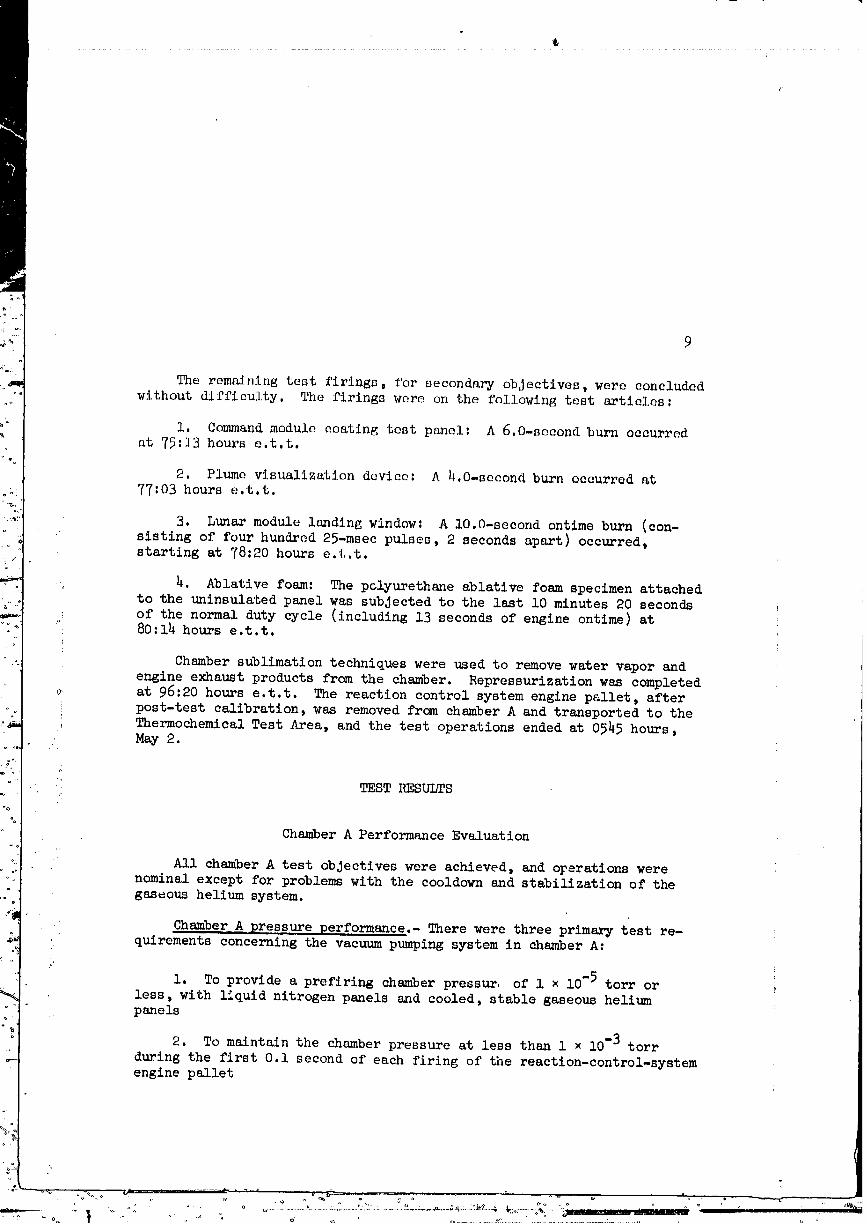
The remaining test firings, for secondary objectives, were concluded
without diffiaulty. The firings were on the following test articles:
i. Command module coating test panel: A 6.0-second burn occurredat 75:13 hours e.t.t,
2. Plume visualization dovieo: A 4.0-second burn occurred at
77:03 hours e.t.t.
B. Lunar module lauding window: A 10.0-second ontlme burn (con-
sisting of four hundred 25-msec pulses, 2 seconds apart) occurred,
starting at 78:20 hours e.t.t.
. 4. Ablative foam: The polyurethane ablative foam specimen attached
to the uninsulated panel was subjected to the last i0 minutes 20 seconds iof the normal duty cycle (including 13 seconds of engine ontime) at80:14 hours e.t.t.
Chamber sublimation techniques were used to remove water vapor andz
engine exhaust products from the chamber. Repressurization was completed
_> at 96:20 hours e.t.t. The reaction control system engine pallet, after
post-test calibration, was removed from chamber A and transported to the
Thermochemical Test Area, and the test operations ended at 0545 hours,May 2.
TEST RESULTS
Chamber A Performance Evaluation
All chamber A test objectives were achieved, and orerations were
nominal except for problems with the cooldown and stabilization of thegaseous helium system.
Chamber A pressure performance.- There were three primary test re-
quirements concerning the vacuum pumping system in chamber A:
1. To provide a prefiring chamber pressur, of 1 × l0"5 torr or
less, with liquid nitrogen panels and cooled, stable gaseous heliumpanels
2. To maintain the chamber pressure at less than 1 × l0-3 torr
during the first O.1 second of each firing of the reactlon-control-systemengine pallet
t,
lO
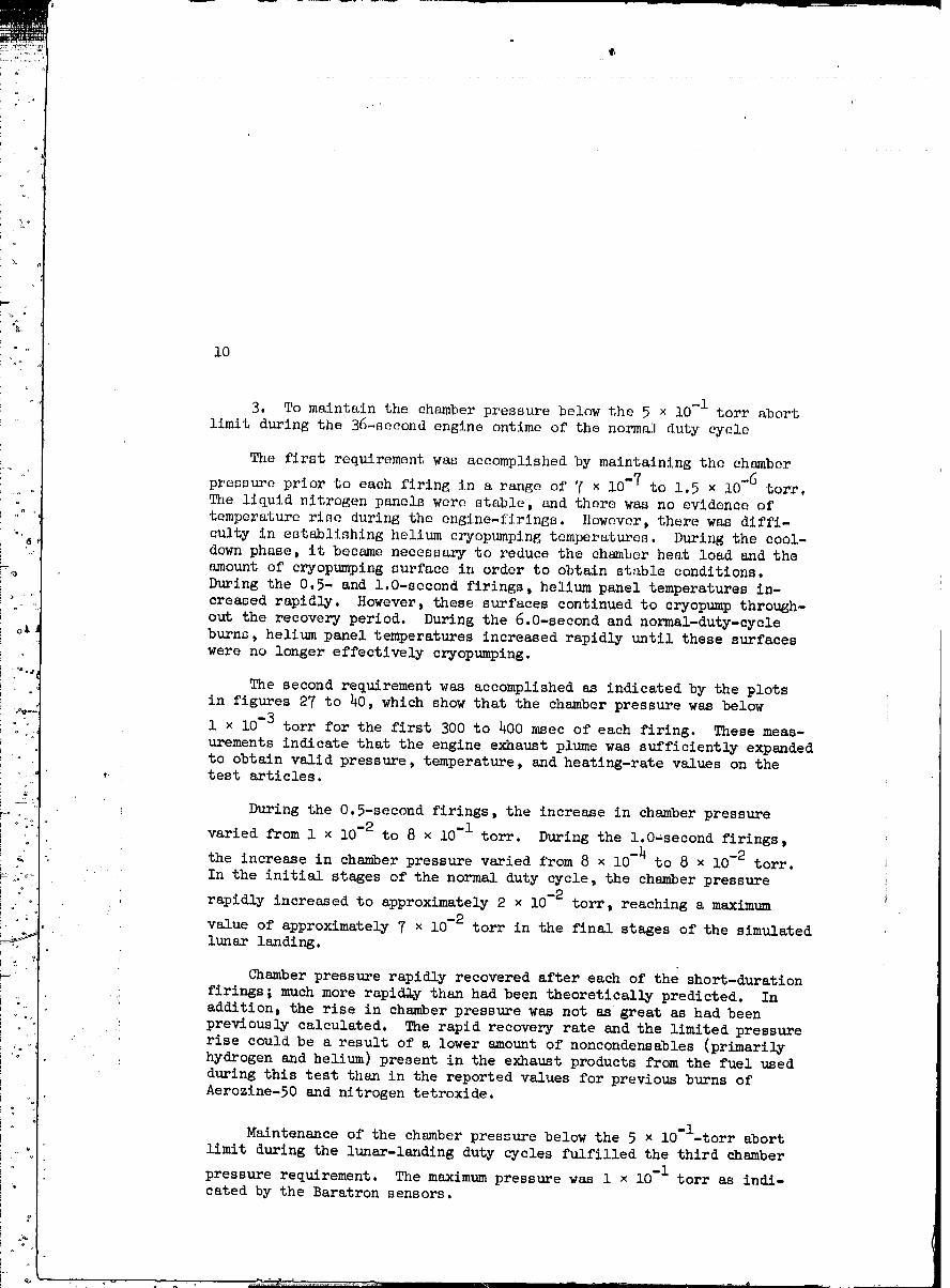
3. To maintain the chamber pressure below the 5 × i0"I torr abort
limit during the 36-second engine ontlme of the normal duty cycle
The first requirement was accomplished by maintaining the chamber
pressure prior to each firing in a range of 7 × 10⁻⁷ to 1.5 × 10⁻⁶ tort.The liquid nitrogen panels were stable, and there was no evidence of
temperature rise during the engine-firings. }lowever, there was diffi-
culty in establishing helium cryopumping temperatures. During the cool-
down phase, it became necessary to reduce the chamber heat load and the
amount of cryopumping surface in order to obtain stable conditions.During the 0.5- and l,O-socond firings, helium panel temperatures in-
creased rapidly. However, these surfaces continued to cryopump through-
out the recovery period. During the 6.0-second and normal-duty-cycle
burns, helium panel temperatures increased rapidly until these surfaces
were no longer effectively cryopumping.
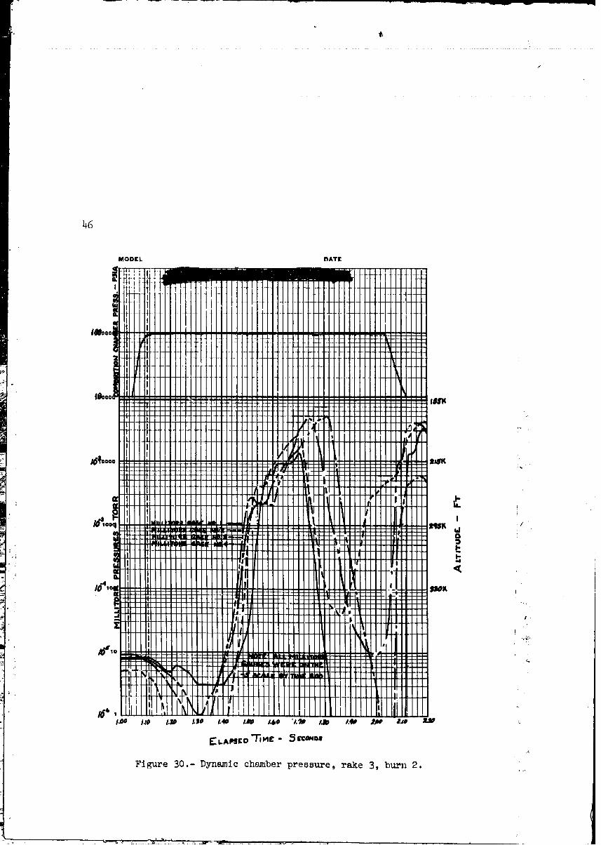
The second requirement was accomplished as indicated by the plotsin figures 27 to 40, which show that the chamber pressure was below
1 × l0-3 torr for the first 300 to 400 msec of each firing. These meas-
urements indicate that the engine exhaust plume was sufficiently expanded
to obtain valid pressure, temperature, and heating-rate values on the, test articles.
During the 0.5-second firings, the increase in chamber pressure
varied from 1 × 10⁻² to 8 × i0-I torr. During the l.O=second firings,
- the increase in chamber pressure varied from 8 × i0-_ to 8 x 10⁻² torr.
t
In the initial stages of the normal duty cycle, the chamber pressure
rapidly increased to approximately 2 × l0-2 torr, reaching a maximum
value of approximately 7 × lO-2 tort in the final stages of the simulated
lunar landing.
Chamber pressure rapidly recovered after each of the short-duration
firings ; much more rapid.%y than had been theoretically predicted. Inaddition, the rise in chamber pressure was not as great as had been
previously calculated. The rapid recovery rate and the limited pressure
rise could be a result of a lower amount of noncondensables (primarily
hydrogen and helium) present in the exhaust products from the fuel used
during this test than in the reported values for previous burns ofAerozine-50 and nitrogen tetroxide.
Maintenance of the chamber pressure below the 5 × lo'l-torr abort
limit during the lunar-landing duty cycles fulfilled the third chamber
pressure requirement. The maximum pressure was 1 × lO-1 torr as indi-cated by the Baratron sensors.
ll
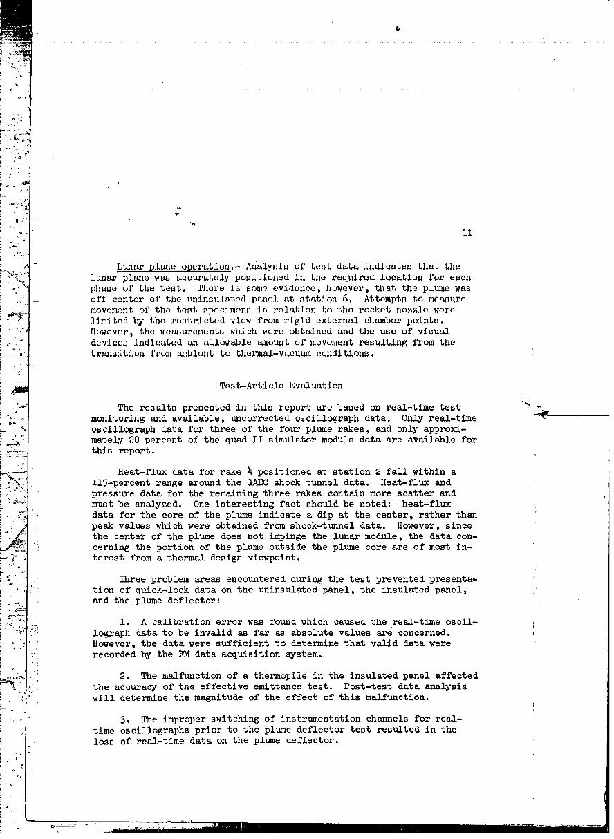
Lunar plane operation._ Analysis of test data indicates that thelunar plane was accurately positioned in the required location for each
phase of the test. There is some evidence, however, that the plume was
off center of the uninnulatnd panel at station 6. Attempts to measure
movement of the test specimens in relation to the rocket nozzle were
limited by the restricted view from rigid external chamber points.
However, the measurements which were obtained and the use of visualdevices indicated an allowable _mount of movement resulting from thetransition from ambient to thermal-vacuum conditions.
Test-Arti cle Evaluation
The results presented in this report are based on real-time test _--
monitoring and available, uncorrected oscillograph data. Only real-time
oscillograph data for three of the four plume rakes, and only approxi-mately 20 percent of the quad II simulator module data are available for
this report.
Heat-flux data for rake _ positioned at station 2 fall within a
-+15-percent range around the GAEC shock tunnel data. Heat-flux and
_ pressure data for the remaining three rakes contain more scatter andmust be analyzed. One interesting fact should be noted: heat-flux
data for the core of the plume indicate a dip at the center, rather than _peak values which were obtained from shock-tunnel data. However, since i
the center of the plume does not impinge the lunar module, the data con-
!i cerning the portion of the plume outside the plume core are of most in-terest from a thermal design viewpoint.
Three problem areas encountered during the test prevented presenta-"_ tlon of quick-look data on the uninsulated panel, the insulated panel,
and the plume deflector:
1. A calibration error was found which caused the real-tlme oscil-
_;_ lograph data to be invalid as far as absolute values are concerned.• However, the data were sufficient to determine that valid data were
! recorded by the FM data acquisition system.
2. The malfunction of a thermopile in the insulated panel affectedi
, the accuracy of the effective emittance test. Post-test data analysis" will determine the magnitude of the effect of this malfunction.
3, The improper switching of instrumentation channels for real-time oscillographs prior to the plane deflector test resulted in theloss of real-time data on the plume deflector.
'_ ......... ' r ' " -- -- ' _]1_ I '_d_ ............ _ " I I ' ' ill 1[ f ......
00000001-TSB06
12
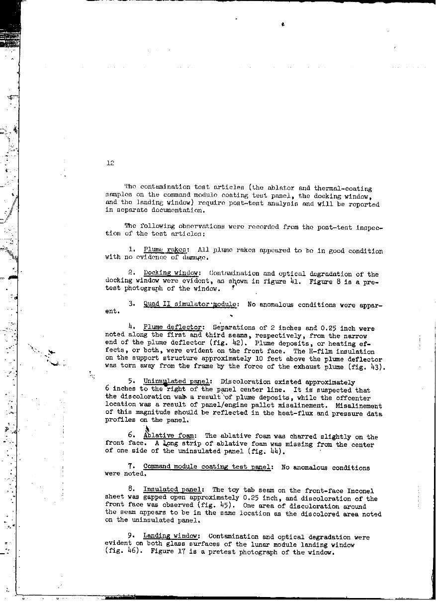
The contamination test articles (the ablator and thermal-coating
samples on the command module coating test panel, the docking window,
and the landing window) require post-test analysis and will be reportedin separate documentation.
The following observations were recorded from the post-test inspec-tion of the test articles:
i. Plume ra_c_: All plume rakes appeared to be in good conditionwith no evidence of dr_age.
2. Doc!_ing window: Contmninatlon and optical degradation of the
docking window were evident, as s_own in figure 41. Figure 8 is a pre-test photograph of the window.
3. Quad II simulator'_odule: No anomalous conditions were appar-ent.
4. Plume deflector: Separations of 2 inches and 0.25 inch were
noted along the first and third seams, respectively, from the narrow
end of the plume deflector (fig. 42). Plume deposits, or heating ef-
t::..._, fects, or both, were evident on the front face. The H-film insulation. on the support structure approximately lO feet above the plume deflector
"_'--,,. was torn awsy from the frame by the force of the exhaust plume (fig. 43).
5. Unlns_lated panel: Discoloration existed approximately
6 inches to the'right of the panel center llne. It is suspected thatthe discoloration wa_ a result 'of plume deposlts, while the offcenter
location was a result of panel/engine pallet misalinement. Misalinement
of this magnitude shottld be re_lected in the heat-flux and pressure data
profiles on the panel.
6. A_lative--foam: The ablative foam was charred slightly on the
front face. A _ng strip of ablative foam was missing from the centerof one side of the uninsulated panel (fig. 44).
7. Command module coating test pareel: No _nomalous conditionswere noted.
8. Insulated panel: The toy tab seam on the front-face Inconel
sheet was gapped open approximately 0.25 inch, and discoloration of thefront face was observed (fig. 45). One area of discoloration around
the seam appears to be in the same location as the discolored area notedon the uninsulated psmel.
9. Landing window: Contamination and optical degradation wereevident on both glass surfaces of the lunar module landing window
(fig. 46). Figure 17 is a pretest photograph of the window.
O0000001-TSB07
13
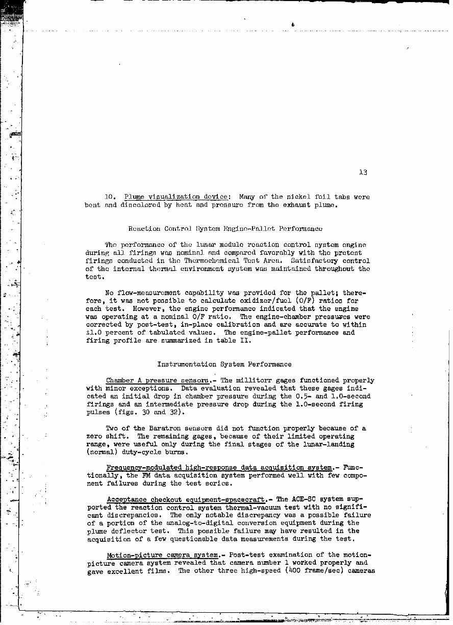
10. Plume visualization devine: Many of the nickel foil tabs were
bent and discolored by heat and pressure from the exhaust plume.
Reaction Control Gystem Englne-Pallet Performanca
The performance of the lunar module reaction control system engine
during all firings was nominal and compared favorably with the pretest
firings conducted in the Thermochemical Test Area. Satisfactory control
of the internal thermal environment system was maintained throughout thetest.
No flow-measurement capability was provided for the pallet; there-
fore, it was not possible to calculate oxldlzer/fuel (O/F) ratios for
each test. However, the engine performance indicated that the enginewas operating at a nominal O/F ratio. The englne-chamber pressures were
corrected by post-test, In-place calibration and are accurate to within
±l.O percent of tabulated values. The englne-pallet performance andfiring profile are summarized in table II.
Instrumentation System Performance
Chamber A pressure sensors.- The millitorr gages functioned properlywith minor exceptions. Data evaluation revealed that these gages indi-cated an initial drop in chamber pressure during the 0.5- and l.O-second
firings and an intermediate pressure drop during the l.O-second firing
pulses (figs. 30 and 32).
Two of the Baratron sensors did not fumction properly because of azero shift. The remaining gages, because of their limited operating
range, were useful only during the final stages of the lunar-lsmding
(normal) duty-cycle burns.
Frequency-modulated hi_h-response data acquisition system.- Func-tionally, the FM data acquisition system performed well with few compo-
: nent failures during the test series.J
i Acceptance checkout equlpment-spacecraft.- The ACE-SC system sup-ported the reaction control system thermal-vacuum test with no signifi-cant discrepancies. The only notable discrepancy was a possible failure
of a portion of the analog-to-digital conversion equipment during the
plume deflector test. This possible failure m_y have resulted in theacquisition of a few questionable data measurements during the test.
Motion-picture camera system.- Post-test examination of the motion-picture camera system revealed that camera number 1 worked properly and
gave excellent films. The other three high-speed (400 frame/see) cameras
/
% Q
00000001-TSBO8
.1h
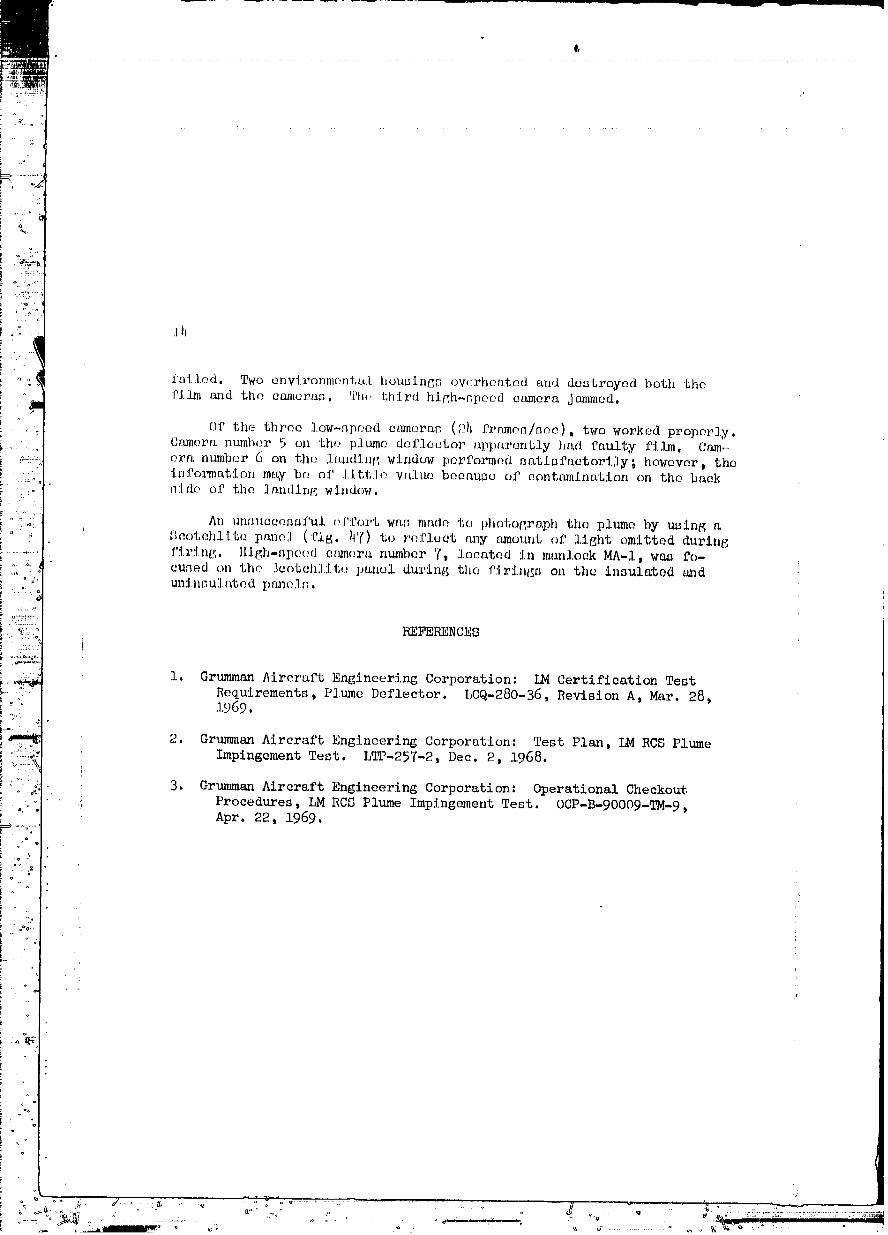
fa_led, Two environmental housing_ ovf:rheatcd and destroyed both thefilm a_id flhe eanlera_, The third high_npeod ea_nera jam_ned,
Of the throe low_.qDeed et_mera_ (P_ frame_/_oe), two worked properly.C_umera number 5 on the _)lume deflector t_pparcntly ht_d faulty film. Cam_
c_ranumber 6 on the landing window performed satisfactorily; however, theinformation may be of little value because of contamination on the backn:Ido of the ]an(ling window.
An unnueeen_ful r_f:t'ortwas made to photograph the plume by using aUcotchllto pauol (fig. I)7)to refluet any _mount of light omitted during
'. firing, High-_pe(M enmo.ra number 7, located, in mon].ock MA-I, was fo-euned on the ]cotchlite panel during the firings on the insulated a_dtu_insuS, ated I)m_e]t_.
REFERENCES
i. Grumman Aircraft Engineering Corporation: LM Certification Test
Requirements, Plume Deflector. LCQ-280-36, Revision A, Mar. 28,1_69.
2. Grumman Aircraft Engineering Corporation: Test Plan, LM RCS Plume
Impingement Test. LTP-257-2, Dec. 2, 1968.
ii' 3. Grumman Aircraft Engineering Corporation: Operational Checkout_ Procedures, LM RCS Plume Impingement Test. OCP-B-90OO9-TM-9,Apr. 22, 1969.
°+ d: d ........ _ ..........<_.... +".°"-_-o+-...... =._....... _-= ......... .. H "_q - ' 4. °," ...............,::..::......................., .-,=+_,
00000001 -TSB09
t,
15
........ _ ',',i,_,_ If .... I I I i '
O0000001-TSBIO
15
TABJ,E II,_, LUHAI/ MODULE REACTION CONTROL SYSTEM
ENdlNI%]'ALLET PERFOI{MAN.O,E gl_f_j_Y
E laj.l.'_d l",ll_.tlm c,lit:lm(+ ,i {_t+mdy-I+t_t+_ _np,] im-Ju, l+_ 1.+,lit. i,:[.11' I '.1,utJt,l+l 'Pr,l]l+ uI'i,l(,l+, 111"+_ o|If%J]1_|" ]II'(Illll_Pi) l
h,'zm.l. (a) |ml.a
+_-:+t+-(.,!l :"): ,_'( P l'tm.. I'ILI_tJb () *.+I !)'_
I.I tt)t_ t' l'Imtt<' Pl_kl 'I' i.O _)'(
+;.+t .'_t+ "S l)_l NIIIt+ I'{£J_tP _' ,9 (+)+(
+_+,ly 3 I'lmm r_t,+ J .0 97 i+,_',.: h J h l']tLlm, _'tdm d .5 9"1' '
.+y:t)() l_ l"im.,, r+_<_,d i.U t)'(
+81]') 8 I'tum(, rl+(: ,e ,5 9(,
_';() ; |I'( {_ I'_U+IIIt' l'{l_e 12 ]. 0 +[)'(I
ll'(:3j 5 _.uad 11 utAtulator IllodUJe ._ 99
h-.+O-t,9 h_'_,'25 5 quad I] _tmulator moduh., l.O 97
50:31 6 Ullflmulatvd pal_el .) 97
56:00 6 Unlnsulatud pamel 1.0 97
61128 7 Insulated panel f36.0 i01
67:07 1 l'l_:e deflector f36.0 102
5-i-69 75 t 13 9 Command-module-coatlnc panel 6,0 103
7?:O3 i0 PlUme visualization device h.O iO1
78120 I0 Landing window • glO.0 --
80tlh 6 Ablative foam h13.0 102
a_otal engine ontime = llh.O s,:conds.
bpositioned 165 inches above the engine exit plane.
' Cposltioned 84 inches above the engine exit plane.
• d?ositioned h5 inches above the engine exit plane.
t'Positioned 22 inches above the engine exit plane,
fDuty cycle consisting of multiple pulses (ref. 2).
MhO0 pulses_ 0.029 second/P00 seconds off.
h_he laSt i0 minutes _0 seconds of the normal duty cycle.
O0000001-TSB11
17
O0000001-TSB12
1_
Figure 2.- Liquid nitrogen panels placed over the side
solar s'imulator.
00000001-TSC01
17
" Figure 3.- Gas-flow diverting baffle suspended under the topsolar simulator.
00000001-TSC02
2O
r,oB.f10w dlv(,rtlnq\/ k
/_ \ /baffl_
/ Liquid.It_,,. /flhroud
/ optlcal baffle at /nolar area
/ /
/ cry¢ pumpinq _ /
/ /_: Fixed support
structure
/ /, /
- / _ 'i4,6,,Chamber pressure/a _I _ _ /
Fixed qratlnq kk specimen
; / Rotating lunar _T"'" /
; , _ plane I :,
:" _ assemblyi
Figure 4.- Cross section, chamber A.
• , o
00000001-TSC03
21
00000001-TSC04
\
22
00000001-TSC05
23
Figure 7.- Plume rake mounted on support structure.
00000001-TSC06
2_
Figure 8.- Docking window mounted on support structure.
00000001-TSC07
00000001-TSC08
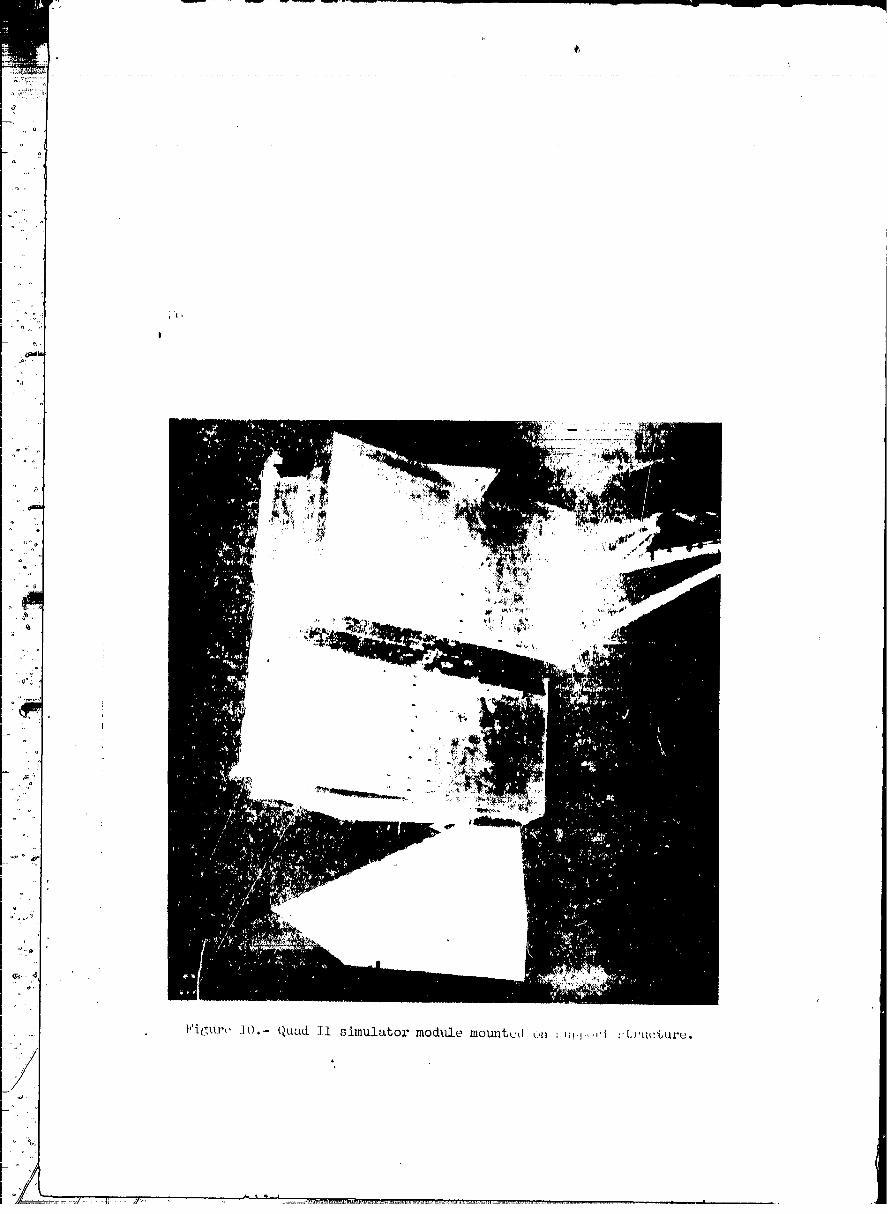
]'igurt, ]0.- Quad II simulatol" modlLle mounted oti ;:tql ,I : t,l'uc%uce.
00000001-TSC09
27
m
O0000001-TSCIO
o
_'i_ure12.- Plume deflector mounted on support structure.
Q
o i
O0000001-TSC11
29
Figure 13.- Uninsulated panel and ablative foam.
00000001-TSC12
3O
Figure 14.- Command module coating test panel mounted onsupport structure.
.........'_ ....._.........."_............"' _" " ....... °'O000-'--0001-TSD01.......
31
Figure 15.- Insulated panel mounted on support structure.
_ " ,_-_,a,...............,r'll F..... III I I i _ lit lIIri i " r--_......
00000001-TSD02
/
Figure 16.- Landing window and plume visualization device.
00000001-TSD03
33
Figure 17.- En@ine pallet, exterior.
000000U1-TSD04
3h
Figure 18.- Engine pallet, interior.
00000001-TSD05
35
TC-I [>_::Z=___TC 25V202 SV203em_' _SVO03 _,,^^_
_- oo4croci I TC-O03
HV20
OR SV SV OR
'--1"-<._1Hv _,HV2OZ IHV ItkLh -'_
o-o t.voo
TC 602R-601
DarkbodyvalvesG-601 SV601 arepanelmounted.
• i PT601_'_, TC601
HV 601. HV 602 603:-601
Figure19.- Schematicdiagramof the reactioncontrol-systemengine-palletpropellantand pressurantsystems.
00000001-TSD06
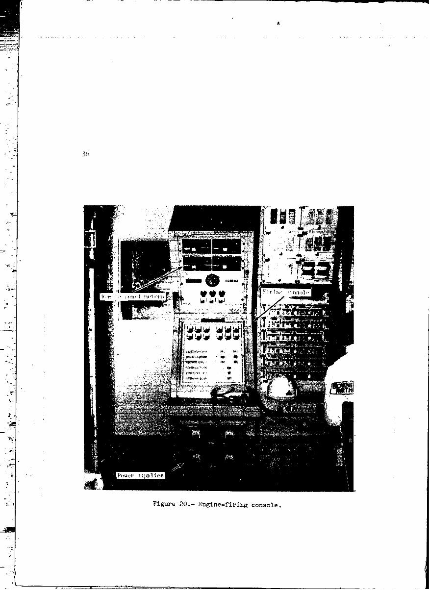
Fi_2e 20.- Englne-firing console.
00000001-TSD07
::7
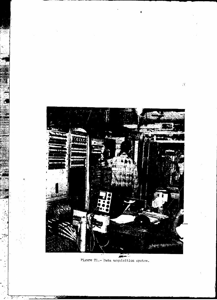
Figure 21.- Data acquisition system.
00000001-TSD08
_t
38
.... : ......... :_;_' ........... L...... _ ........................... T I'TII" _1 1111 r,,'" ,,,. "................
00000001-TSD09

39
II _ A_E-ScEQUII_IF,HTII lI _ CQl_mObI I Rc_oX .
I ______(]_.__,___ _ DIa:_T_. tI _Om_ZTZONF,R I I l _(_r>_RT_ l
I _w DATA MOPUbA'Z'_i ,.,T_ r_--l_ (PeM)DATAtl ' I
l E(_OlVgV_ATOR !/ A,NAXXX}DATA
'Z_T tR_Z.,-TZ_DATA 'wlnEOO_nB IASTXCZ,,Se ,TASU',..aTZOaVZA I (UWSFa'T'a_IJ_UDD.
[ DATAiI (DOW_-LZmC)tI c_tr_,_ ,, l
PALI._T 'II. _J_ (cm_) I
" I z,z_ , ..lt tmz_ DZSr_l
(_-L%mC) C-STA_T0C141_I._ MODULE
AG'TIVA_.... " REQUIREDI_IRINO
] PPD FIRIN_ L I DIGITAL TEST-I PROFILE '
COBOL III _THERMAL UP-LINK
t DATA DISPLAY 8UB-PROGP_M
,... Figure _3.- Acceptance Checkout Equipment-Spacecraft,block diagram.
O0000001-TSDIO
4o
O0000001-TSD11
41
Figure 25.- Quartz lamp heater.
00000001-TSD12
h2
00000001-TSE01
43
MODEL DATE-
• !
I_ tii_, II|K
J
00000001-TSE02
44
MODEL DATE
I_rK
lrlo
00000001-TSE03
45
MODEL DATE
00000001-TSE04
t,
4G
MODEL _ATE
Figure 30.- Dynamic chamber pressure, rake B, burn 2.
00000001-TSE05
_7
MODI_ DMT.E
00000001-TSE06
48
MODEL OATK
O000000i-TSE07"
iF,
/,
' 49
r. -.-'--'.._ _r, ..... _ ..... _ - 7 ...... J ..... _ ---' ---- ,.,..i ...... I I FI ' [
_"u_'I<_ ._,,_ • "___ ,<, _, ....... _c_ _I__ll_._'+_+_tl_,,',-++'_t_'=_:_"_*__'_ _ l:_, _'_l'_li I .... _ ;::r _il IIII II I
O0000001-TSEO8
5o
MODEL DATE
00000001-TSE09
/,
, 51
MOD_L DATE
!r lgt'°
O0000001-TSEI 0
I,
52
MODEk DAVE
_LAPS£O'nME - S£'¢ONDS
Figure 36.- Dynamic chamber pressure, uninsulated panel, burn 2.
00000001-TSE11
53
ri
aJ
GJ
!°QJ
°_
!
.r,I
O0000001-TSE12