nasa apollo fmea
DESCRIPTION
NASA's FMEA system for the Apollo missionsTRANSCRIPT
... ...... .:.:.: APOLLO PROGRAM .g ii.
fi. .:.e.
PROCEDURE
FOR
FAILURE MODE, EFFECTS, AND
CRITICALITY ANALYSIS
(FMECA) i
--
AUGUST 1966 -
. REPRODUCED BY NATIONAL TEC HN I C A L INFORM AT I ON SERVICE
US. DEPARlYENl OF COMMERCE SPRINGFIELD, VA. 22161
NATIONAL AERONAUTICS AND SPACE ADMINISTRATION
WASHINGTON, D.C. 20546

N O T I C E
T H I S DOCUM.ENT HAS B E E N R E P R O D U C E D
FROM T H E B E S T C O P Y F U R N I S H E D U S B Y
TEE SPONSORING AGENCY. A L T H O U G B I T
I S RECOGNIZED T E A T C E R T A I N P O R T I O N S
AR’E I L L E G I B L E , IT IS B E I N G R E L E A S E D
I N T H E I N T E R E S T OF MAKING A V A I C A B L E
A S MUCH I N F O R M A T I O N A S . P O S S I B L E .
’ . I
d 7 d - 76/77 RA- 006 - 0 13- 1A
PROCEDUREFOR
FAILURE MODE, EFFECTS, AND CRITICALITY ANALYSIS
(FMECA)
August 1966
Prepared by Apollo Reliability and Quality Assurance Office National Aeronautics and Space Administration
Washington, D. C . 20 546
PREFACE
This document is an official release of the Apollo Program Office. Many of the
procedures and methods a re already being carried out. The extent to which this
guideline should be implemented at the present stage of program matrurity should be evaluated by comparing the benefits to be derived therefrom with the problems of implementation, including cost.
The principal criteria in judging the value of applying all the procedures of this guideline a re the need for these procedures to accomplish identification and rank- ing of potential failures critical to hardware performance and crew safety. Other
considerations, such as, design/development testing, noncriticality of the equip- ment to system operational success, past experience, and reliability analyses, may preclude the need to perform all the procedures of this guideline.
n Q
94 ' s J . Willoughby L
Acting Director Apollo Reliability and Quality

Paragraph
1.1
1 . 2
1 . 3
1 . 4
1 .5
1 . 6
1 . 7
2 . 1
2 . 1
TABLEOFCONTENTS
Title
SECTION 1-INTRODUCTION
PURPOSE
SCOPE
DEFINITION O F FMECA
OBJECTIVES O F FMECA
USE O F FMECA
FMECA RELATION TO THE RELIABILITY PREDICTION, ASSESSMENT, AND CREW SAFETY MODELS
PROCEDURE O F FMECA
SECTION 2-PROCEDURE FOR FAILURE MODE AND EFFECTS ANALYSIS
SYSTEM DEFINITION
1 ACCOMPLISHMENT
2 . 1 . 2 DOCUMENTATION
2 .2 RELIABILITY LOGIC BLOCK DIAGRAM
2 .3 FAILURE MODE AND EFFECTS ANALYSIS
SECTION 3-PROCEDURE FOR CRITICALITY ANALYSIS
3.1 CRITICALITY PROCEDURE
3 . 2 CRITICALITY FAILURE MODE IDENTIFICATION
3.3 CRITICALITY NUMBER CALCULATION
3.3.1 Cr CALCULATION EXAMPLE
3 . 3 . 2 FORMAT FOR Cr CALCULATION
SECTION 4-SUMMARY O F FMEA AND CA
4.1 PREPARATION O F FMECA SUMMARY
4 .2 CRITICALITY LIST - -
Preceding page blank _ . - _ - -
Page
1-1
1-1
1-1
1-2
1-2
1-3
1-3
2-1
2-1
2-3
2-4
2-6
3-1
3-2
3-3
3-5
3-5
4-1
4-2
V
TABLE OF CONTENTS (Cont.)
Title Paragraph -
APPENDIX A-REF ERENCE DOCUMENTS
APPENDIX B-DEFINITIONS
Page
A- 1
B- 1
LIST OF ILLUSTRATIONS
Figure Title
2-1
2-2
3-1
4-1 General FMECA Summary Format
General Reliability Logic Block Diagram Scheme General Format for Failure Mode and Effects Analysis
General Format for Criticality NEmber Calculation
Page
2-5
2-7
3-7
4-3
SECTION 1
INTRODUCTION
1.1 PURPOSE
This document provides guidelines for the accomplishment of Failure Mode, Ef-
fects, and Criticality Analysis (FMECA) on the Apollo program. It is a procedure for analysis of hardware items to determine those items contributing most to sys- tem unreliability and crew safety problems.
1.2 SCOPE
This document is applicable to all NASA activities with cognizance over design,
development, and test of Apollo flight, ground, and related equipment which have
major impact on mission success. It may be invoked in equipment contracts in whole or in part, where design or development is involved, as a portion of the re- liability engineering and as the guideline for carrying out the activity, predicated on budget considerations, equipment criticality, schedules, and other factors.
The ground rules for the use of FMECA may call for substitute overstress tests on structural parts o r for other design/development tests of the system in place of the FMECA, or these rules may not require anFMECAon those parts of the system that are established by preliminary FMECA to be noncritical to system operational success.
1.3 DEFINITION OF FMECA
Failure Mode, Effects, and Criticality Analysis is a reliability procedure which
documents all possible failures in a system design within specified ground rules,
determines by failure mode analysis the effect of each failure on system opera- tion, identifies single failure points, i. e. , those failures critical to mission success or crew safety, and ranks each failure according to criticality category
of failure effect and probability of occurrence. This procedure is the result of
two steps: the Failure Mode and Effect Analysis (FMEA), the Criticality Analysis
(CA) . In performing the analysis, each failure studied is considered to be the only failure in the system.
1- 1
a.
b.
C.
d.
e.
f.
g.
1.4 OBJECTIVES OF FMECA
The FMECA provides: The design engineer with a method of selecting a design with a high
probability of operational success and crew safety. Design engineering with a documented method of uniform style for assessing failure modes and their effect on operational success of
the system. Early visibility of system interface problems. A list of possible failures which are ranked according to their category of effect and probability of occurrence.
Identification of single failure points critical to mission success or to
crew safety. Early criteria for test planning.
Quantitative and uniformly formatted data input to the reliability pre-
diction, assessment, and safety models.
1 .5 USE OF FMECA
The FMECA is normally accomplished before a reliability prediction is made to
provide basic information. An FMECA should be initiated as an integral part of the early design process of system functional assemblies and should be periodi- cally updated to reflect design changes. This analysis may also be used to pro- vide a model for analyzing already-built systems.
An updated FMECA is a major consideration in the design reviews, inspections,
and certifications defined in NASA Apollo Program Directive No. 6 , Office of Manned Space Flight, August 12, 1965, subject, "Sequence and Flow of Hardware Development and Key Inspection, Review and Certification Checkpoints. ('
An FMECA should be performed initially at the highest system level feasible.
The purpose of this analysis should be to determine the criticality ranking of the major system elements so FMECA program effort may be scoped and allocated
for subsystems and equipments critical to system operational success.
1-2
E L L
1.6 FMECA RELATION TO THE RELIABILITY PREDICTION, ASSESSMENT AND CREW SAFETY MODELS
(See ffApollo Reliability Estimation Guidelines", RA 006-007-.l. )
FMECA is a simplified reliability estimation tool. It - cannot substitute for the reliability prediction and assessment or for crew safety models and their analysis.
FMECA provides quick visibility of the more obvious reliability problems ranked
according to their importance to system operational success. Changes made in the system to remove or reduce these more obvious reliability problems will
usually restructure major parts of the system. This will make the more detailed analysis of the reliability models an inefficient process for upgrading system re- liability during the early stages of design when changes are being made rapidly;
hence, the FMECA is particularly appropriate during this period. The FMECA should be reviewed by the designer on a timely basis.
After a satisfactory systemdesign basedupon estimates has been obtained, a de- tailed reliability analysis of the system design is made using the reliability mathe- matical models. This verifies quantitative reliability goals, verifies the adequacy of redundancy or other failure preventive means built into the system, and discloses
subtle reliability problems involving multiple concurrent failures in the system.
Where the detailed analysis results in a redesign of portions of the system, a
repetition of the FMECA on these redesigned portions and those portions affected by the redesigned portions is accomplished. The FMECA insures that the design engineers have considered all conceivable failure modes in the new design and their effect on system operational success. Also, the FMECA provides design engineering judgment input to the reliability models.
1.7 PROCEDURE OF FMECA
FMECA is performed in two basic steps:
(FMEA) and (2) Criticality Analysis (CA). The combination of these two steps
provides: (3) Failure Mode Effects and Criticality Analysis (FMECA) e Section2 provides step-by-step procedures for FMEA; Section 3 provides step-by-step procedures for CA; and Section 4 combines the FMEA and CA into the FMECA.
(1) Failure Mode and Effects Analysis
1-3

2.1
SECTION 2
PROCEDURE FOR FAILURE MODE AND EFFECTS ANALYSIS
SYSTEM DEFINITION
2.1.1 ACCOMPLISHMENT
Accomplishment of an FMEA on a system consists of the following general steps:
a .
b.
Define the system to be analyzed. Obtain all descriptive informa- tion available on the system to be analyzed. This should include
such documents as functional block diagrams system descriptions , specific ations drawings system component identification coding, operational profiles environmental profiles , and reports bearing
on reliability such as feasibility o r reliability studies of the system being analyzed and of past similar systems.
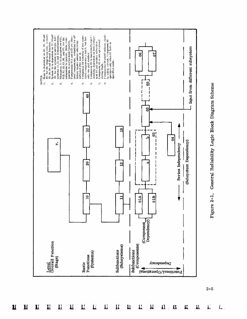
Construct a reliability logic block diagram of the system to be ana-
lyzed, similar to that shown in Figure 2-1, for each equipment con- figuration involved in the system's use.
The diagrams are developed starting at the top level of the system and extending downward to the lowest level of system definition at the time of analysis. These reliability logic block diagrams are not descriptive block diagrams of the system that show the interconnec- tion of equipments. The reliability logic block diagrams used for an FMEA show the functional interdependencies between the system
components so that the effects of a functional failure may be readily traced through the system.
All redundancies or other means for preventing failure effects should be shown as functional blocks or notes.
Where certain functions a re not required in an operational time
phase, the information may be shown by a dotted block as in the case of component 05 in Figure 2-1 or by other suitable means.
c . At the lowest level of system definition, as developed from the top down, analyze each failure mode of the system component and its effect on the system. Where system functional definition has not reached the level of identification of the system functions with the specific type of hardware that will perform these functions , the FMEA should be based upon failure of the system functions giving the general type of hardware envisioned as the basis for system
design.
Four basic conditions of component o r functional failure should be
considered: Premature operation.
0 Failure during operation.
Failure to operate at a prescribed time. Failure to cease operation a t a prescribed time.
The FMEA assumes that only the failure under consideration has occurred. When redundancy or other means have been provided in the system to prevent undesired effects of a particular failure, the redundant element is considered operational and the failure effects terminate at this point in the system. When the effects of a failure
propagate to the top level of a system and cause the system to fail, the failure is defined as a critical failure in the system.
When an FMEA is being performed on an already-built system, the analyst may find cases where redundancies or other means of pre- venting failure effects do little to improve the failure situation o r where the redundancies may actually worsen it. These cases should
be reported for the next higher level. Where the scope of the FMEA
program permits, the redundancy or other failure effects preventive means should not halt the continuation of the failure effects analy- sis toward the top level of the system.
d. Document each potential failure mode of each system component and
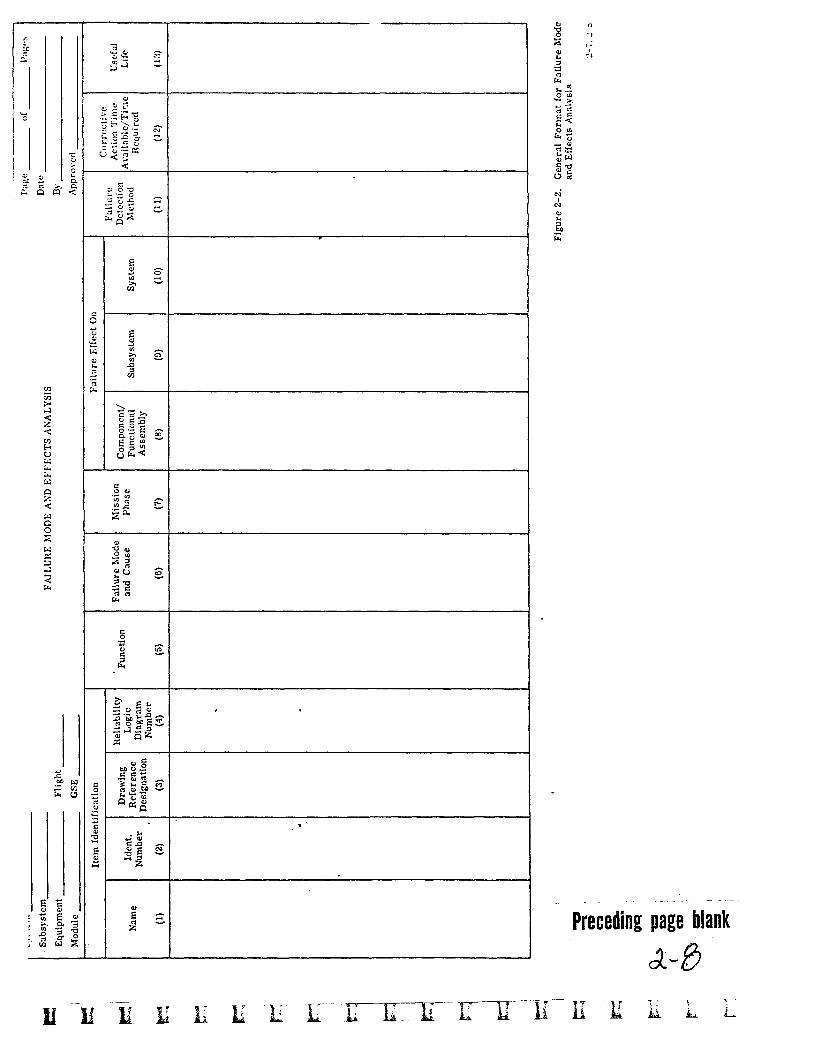
the effects of each failure mode on the system by completing an FMEA format similar to that shown in Figure 2-2. Instructions for
filling out the FMEA format a re given on pages 2-6 through 2-10.
2-2
L e
2.1.2 DOCUMENTATION
The following documentation is representative of the information required for
system definition and analysis :
2.1.2.1 System Technical Development Plans
To define what constitutes and contributes to the various types of system failure, the technical development plans for the system should be studied. The plans will normally state the system objectives and specify design requirements for opera- tions, maintenance, test, and activation. Detailed information in the plans will normally provide a mission o r operational profile and a functional flow block dia- gram showing the gross functions that the system must perform. Time diagrams and charts used to describe system functional sequence will aid the analyst to de- termine the time feasibility of various means of failure detection and correction in the operating system. Also required is a definition of the operational and en-
vironmental stresses that the system is expected to undergo and a list of the ac- ceptable conditions of functional failure under these stresses.
2.1.2.2 Trade-off Study Reports
To determine the possible and more probable failure modes and causes in the system, trade-off study reports should identify the areas of marginal design and should explain the design compromises and operating conditions agreed upon.
2.1.2.3 System Description and Specifications
The descriptions and specifications of the system's internal and interface func- tions, starting at the highest system level and progressing to the lowest level of
system development to be analyzed, are required for construction of the FMEA reliability logic block diagrams. A reliability logic block diagram as used in the FMEA and as described in paragraph 2.1.1.6 shows the functional interdependen- cies within the system and permits the effects of a failure to be traced. System
descriptions and specifications usually include either o r both functional and equip- ment block diagrams that facilitate the construction of the reliability logic block diagrams required for the FMEA. In addition, the system descriptions and spec-
ifications give the limits of acceptable performance under specified operating and environmental conditions.
2- 3
2 . 1 . 2 . 4
Equipment design data and drawings identify the equipment configuration perform-
ing each of the system functions.
Equipment Design Data and Drawings
Where functions shown on a reliability functional block diagram depend on a re- placeable module in the system, a separate FMEA may be performed on the in- ternal functions of the module. The effects of possible component failure modes in the module on module inputs and outputs then describe the failure modes of the module when it is viewed as a system cow-ponent.
2 . 1 . 2 . 5 Coding Systems
For consistent identification of system functions and equipment, an approved cod- ing system should be adhered to during the analysis. Use of coding systems com-
mon to the overall program are preferable.
2 . 1 . 2 . 6 Test Results
Tests run on the specific equipment under the identical conditions of use a re de-
sired. When such test data are not available, the analyst should collect and analyze
the data obtained from studies and tests performed during current and past pro- grams on equipment similar to those in the system andunder similar use conditions.
2 . 2 RELIABILITY LOGIC BLOCK DIAGRAM
The next step of the FMEA procedure is the construction of a reliability logic block diagram of the system to be analyzed. The general reliability logic block diagram scheme for a system is shown in Figure 2-1. This example system is for a space vehicle stage, and the notes given explain the functional dependencies of the stage components.
A system component at any level in the stage system may be treated as a system and may be diagrammed in like manner for failure mode and effects analysis.
The results of the component's FMEA would define the failure modes critical to the component's operation, i. e. , those that cause loss of component inputs o r outputs. These failure modes will then be used to accomplish the FMEA at the
2-4
3
2- 5

next higher system level. This procedure ultimately leads to an FMEA for the stage, the space vehicle, and space system.
All system redundancies o r other means for preventing failure effects are shown in the reliability logic block diagram. This is because in single failure analysis, when a means exists to prevent the effects of a failure, the failure cannot be criti- cal above the system level where the preventive means is effective.
2 . 3 FAILURE MODE AND EFFECTS ANALYSIS
The FMEA and its documentation a re the next steps of the procedure. These a re accomplished by completing the columns of an FMEA format similar to that given
in Figure 2-2 as follows :
Column Number Explanation or Description of Entries
Name of system function o r component under analysis for failure modes and effects. Breakdown of a system for analysis should normally be down to the lowest prac- ticable level at the time of the FMEA. In special cases such as electronic systems using integral modular units as system building blocks, &e modules may be listed rather than listing its parts.
(1)
(3)
(4)
Drawing number by which the contractor identifies and describes each component o r module. These drawings should include configuration, mechanical, and electrical characteristics.
Reference designation used by manufacturer to identify the component o r module on the schematic. Applicable schematic and wiring drawing numbers should also be listed.
Identification number of FMEA reliability logic block diagram and of the function.
Concise statement of the function performed.
Give the specific failure mode after considering the four basic failure conditions :
Premature operation. 0
0 Failure during operation.
Failure to operate at a prescribed time. Failure to cease operation at a prescribed time.
I
__ . .. . _ _
Preceding page blank
Column Number Explanation o r Description of Entries
(6 ) (Cont.) For each applicable failure mode, describe the cause including operational and environmental stress factors , if known.
Phase of mission in which critical failure occurs, e. g. , Prelaunch: checkout, countdown; Flight: boost phase , earth orbit, translunar , lunar landing, etc. Where the subphase, event, or time can be defined from approved operational o r flight profiles, the most definitive timing information should also be entered for the assumed time of critical failure occurrence. The most definitive time information that can be determined should also be given for the failure effects under the columns titled "Failure Effects On.
A brief statement describing the ultimate effect of the failure on the function or component being analyzed. Examples of such statements a r e component rendered useless , component's usefulness marginal, or struc- turally weakened to unacceptable reliability level. Tim- ing information as described under (7) should be given.
A brief description of the effect of the failure on the next higher assembly. Timing information as described un- der (7) should be given as to time of failure effect.
A description of the effect of the component failure on the system. For the major systems of the overall space system, these effects a re divided into failures affecting mission success and failures affectin, 0' crew safety. Examples of failures affecting mission success a r e abort, limited mission, degrade mission objectives , and vehicle loss, scrub, or hold, etc. Examples of failures affecting crew safety a re total loss of crew, partial loss of crew, and loss of redundancy. Forlower level systems where effects on the overall space system are unknown, the effects of a failure on the system un- der analysis may be described as loss of system inputs o r outputs. Examples of such effects are loss of signal output, loss of output pcessure, and shortedpower input. Timing information as described under (7) should be given.
A description of the methods by which,the failure could be detected. Identify which of the following categories the failure detection means falls under:
0 On-board visual/audible warning devices. 0 Automatic abort-sensing devices. 0 Ground operational support system failure-
sensing instrumentation.
2-9
Column Number
(11) (Cont.)
Explanation or Description of Entries
0
0 None.
Flight telemetry, ground support equipment con- sole display, etc.
Timing information as described under (7) should be given with respect to the reaction time available between time of component failure, time of detection, and time of critical failure effect.
A description of what corrective actions that the flight crew and the ground crew could take to circumvent the failure. If applicable, the time available for effective action and the time required should be noted.
State the useful life of item under given environmental conditions.
2-10
1;: C t
SECTION 3
PROCEDURE FOR CRITICALITY ANALYSIS
3.1 CRITICALITY PROCEDURE
The Criticality Analysis (CA) is reliability procedure which determines a system component's magnitude of criticality to system operational success .
The CA is performed in two steps:
a. Identify critical failure modes of all components in the FMEA for each
equipment configuration in accordance with the categories listed in
paragraph 3 . 2 . For FMEA's of lower level systems where the effect of failure modes on mission success or crew safety cannot be deter- mined, the critical failure modes will be those that cause failure of one or more of the system's inputs or outputs.
The specific type of system failure is expressed as a unique loss state- ment. For major Apollo systems, example loss statements a re crew loss, abort, and vehicle scrub. For lower level systems, exampleloss statements a re output signal loss, input power shorted, and loss of output pressure.
b. Compute Critical Numbers (C,) for each system component with criti- cal failure modes. The method is given in paragraph 3 .3 , and a for- mat for the data is shown in Figure 3-1.
The C for a system component is the number of system failures of a specific type expected per million missions due to the component's
critical failures modes.
r
Where the factors involved in the calculation of system component criti-
cality numbers vary with mission time, the mission is dividedinto mis-
sion phases such that the change in the factors a re negligible. A criti-
cality number is computed for each mission phase for a given loss statement.

The analyst responsible for the CA at the next higher system level con-
tinues the analysis using lower level CA's. Where the loss of an input or output of a lower level equipment is critical to equipment operational
success at his system level, action should be taken to design the criti- cality out of the system o r to reduce its criticality to an acceptable
level by improvements in basic reliability, redundancy, o r other means,
3.2 CRITICAL FAILURE MODE IDENTIFICATION
The first step of CA is the identification of critical failure modes fromthe FMEA's on the system.
Critical failure modes at higher levels in the overall space system should be identified according to approved nonambiguous loss statements.
ing categories, according to Reference 5, Appendix A, paragraph 3.3.3, may be used:
The follow-
HARDWARE CRITICALITY CATEGORIES FOR FLIGHT HARDWARE
Category 1-Hardware, failure of which results in loss of life of any crew mem- ber. This includes normally passive systems, i. e. , emergency de- tection system, launch escape system, etc.
Category 2-Hardware, failure of which results in abort of mission but does not cause loss of life.
Category 3-Hardware, failure of which will not result in abort of mission nor cause loss of life.
HARDWARE CRITICALITY FOR GROUND SUPPORT EQUIPMENT
CategoryA-Hardware, failure of which results in the loss of life of any crew member or ground crew member.
Category B-Hardware, failure of which results in abort of mission but does not cause loss of life.
Category C-Hardware, failure of which will not result in abort of mission nor cause loss of life.
At the lower system level where it is not possible to identify critical failure modes according to loss statements under the six categories above, approved loss state- ments based upon loss of system inputs o r outputs should be used (See para-
graph 3.la.). Kennedy Space Center loss statements can be found in Reference 9
of Appendix A. Marshall Space Flight Center loss statements can be found in Reference 8 of Appendix A.
The loss statement used to identify a critical failure mode in a system should be prefixed with the word "actual, " "probable, " "possible, " or "none'' which repre- sents the analyst's judgment as to the conditional probability that the loss will oc-
cur given that the failure mode has occurred.
3 . 3 CRITICALITY NUMBER CALCULATION
The second step of the CA procedure is the calculation of Criticality Numbers (C,)
for the system components with critical failure modes.
A Cr for a system component is the number of system failures of a specific type expected per million missions due to the component's critical failure modes.
The specific type of system failure is expressed by the critical failure mode loss statement discussed in paragraph 3 . 2 .
For a particular loss statement and mission phase, the C for a system compo- nent with critical failure modes is calculated with the following formula:
r
n 'r n = l
n = l , 2, 3, ..., j
where :
Cr = Criticality number for the system component.
j = Total number of critical failure modes in the system component un- der loss statement.
p = Conditional probability that the failure effects of the critical failure mode occur given that the critical failure mode has occurred.
Q! = Fraction of all failures (or h ~ ) experienced by a component and that a r e due to the particular failure mode under consideration.
3-3
KE = Environmental factor which adjusts h~ for difference between envi- ronmental stresses when hG was measured and the environmental stresses under which the component is going to be used.
KA = Operational factor which adjusts h~ for the difference between oper- ating stresses when hG was measured and the operating stresses under which the component is going to be used.
hG = Generic failure rate of the component in failures per hour or cycle.
t = Operating time in hours o r number of operating cycles of the component.
n = An index of summation for critical failure modes in the system com- ponent that fall under a particular loss statement.
The factor /3 is the probability of loss discussed in paragraph 3 . 1 , and should be limited to the following values :
Failure Effects
Actual Loss Probable Loss Possible Loss None
Value of Beta
100 Percent > 10 Percent to < 100 Percent 0 Percent to 10 Percent 0 Percent
The expression (PcvKEKAhGt - lo6) is the portion of Cr for the component due to one of its critical failure modes under a particular loss statement. After calcu- lation of the part of Cr due to each of the component's critical failure mode under the loss statement, these parts a re summed for all critical failure modes as indi- cated by
, t . n = l
A failure mode failure rate is represented in the formula for Cr by the product of
the terms Q! , KE , KA, and AG. These terms should be replaced by actual failure
mode failure rates determined from the test program as they become available.
A sample calculation is given on the following page.
3.3.1 Cr CALCULATION EXAMPLE
For a given mission phase:
Given: System component with hG = 0.05 failures per lo6 operating hours,
KA = 10, KE = 50,
a = 0.30 for one critical failure mode under loss statement, and
a = 0.20 for the second critical failure mode under the same loss stat em ent .
Let p = 0.50 and t = 1 0 hours
Find: Cr for this system component during this mission phase.
Solution:
For the first critical failure mode, i. e. , for n = 1
(PaKEKAAGt lo6.)
For the second critical failure mode; i .e. , for n = 2
(/3aKEKAhGt - lo6) = (0.50) (0.20) (50) (10) (0.05 X (10) (lo6) = 25
j = 2 and
= (0.50) (0.30) (50) (10) (0.05 X lom6) (10) (lo6) = 38 1
2
(/3aKEKAhGt * lo6) = 38 + 25 = 63 n ‘r
n = l
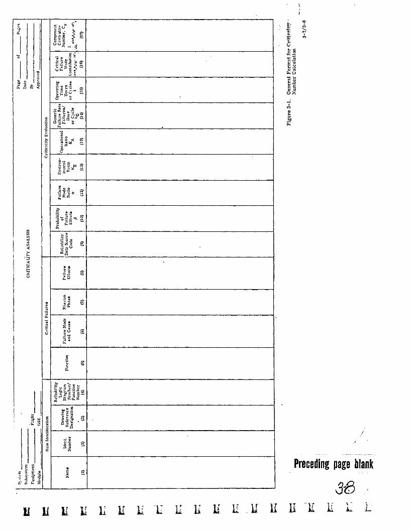
3.3.2 FORMAT FOR Cr CALCULATION
The columns of the format for C calculations shown in Figure 3-1 should be filled out as follows:
r
Column Number Explanation or Description of Entries
(1) - (7) These columns duplicate the information given in the same columns of the FMEA format shown in Figure 2-2 and are explained in paragraph 2.3.
3-5

Column Number Explanation or Description of Entry
Failure effects given for the highest system level on the FMEA.
(8)
The source of reliability information used for each cal- culation should be identified in this column.
(9)
(10) - (16) Enter the information required for the calculation of the portion of the component's criticality number due to each of its critical failure modes.
(17) Enter the component's criticality numbers in this col- umn. This is the sum of the portions of the criticality number entered in column (16) due to a particular mis- sion phase and loss statement.
I
Preceding page blank

SECTION 4
SUMMAKY OF FMEA AND CA
4.1 PREPARATION OF FMECA SUMMARY
The procedure is a method for combining the criticality values by mission phase
to develop an overall summary.
Preparation of the FMECA summary is developed from the FMEA and CA anal-
ysis discussed in Sections 2 and 3 and is accomplished by completing a form
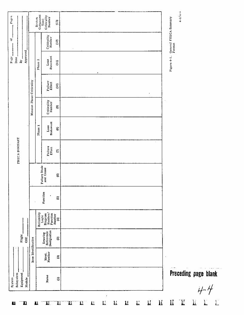
similar to that given in Figure 4-1. Instructions for completing the form are given below.
A criticality list is prepared. Crit ical system components a re grouped accord- ing to loss statement and a re listed in the groups in descending order according to the magnitude of their total criticality number for the particular loss state- ment. A system component's total criticality number for a particular loss state- ment is computed from the FMECA summary information. Examples of ground rules for this are given below.
A general FMECA summary form is shown in Figure 4-1. The columns are
completed as follows : Column Number Explanation or Description of Entries
Identification and function of the system component with critical failure modes is the same as are those for the FMEA format in Figure 2-1 which is described in paragraph 2.3.
For each system component, enter its critical failure modes and, if known, their cause.
If the critical failure mode has an effect during Phase I of the mission, its effect on the system is given in col- umn (7) with mission time or event. The approved loss statement for the effect is given in column (8). The portion of the total criticality number calculated for the critical failure mode according to the example given in paragraph 3.3.1 is entered in column (9).
4-1
Column Number Explanation or Description of Entries
(10) - (12) Where the critical failure mode has an effect during Phase 2 of the mission, columns (10)-(12) are completed in the same manner as in columns (7)-(9). This format should be extended to include all mission phases.
4.2 CRITICALITY LIST
A total criticality number may be computed for each system component according to approved ground rules. An example of ground rules is as follows:
a. Each criticality number in the mission phase columns shall be multiplied by an approved importance weighting factor for its particular loss statement.
Example for stage/module level FMECA: Kills Crew = 1.0, Causes abort = 0 . 5 , Launch scrub = 0.4, Launch delay = 0.3.
Example for subsystem level FMECA: Loss of critical output or input which could lead to crew loss = 1.0, Loss of noncritical input or output = 0.2, Annoyance failure = 0.1. These examples are given only to convey the intent. A lengthy list of statements of actual loss may be ranked in relative importance by this means. A given critical failure mode in a system com- ponent shall occur only once during the mission; therefore, the largest weighted criticality num- ber for a critical failure mode will be selected from among the mission phase columns for calculation of the component's total criticality number. A component's total criticality number for a particular loss statement shall be the sum of the weighted criticality numbers with the same loss statement selected from the mission phase col- umns according to ground rule b, preceding. Each total criticality number with loss statement for a system component as calculated by ground rule c. above shall be entered in column (13) of the FMECA summary format.
b.
c.
d.
The last step of the FMECA is the preparation of the criticality list. Critical
system components are grouped according to loss statement and are listed in the groups in descending order according to magnitude of their total criticality number
4-2
I
I
Preceding page blank
for the loss statement. A system component may appear in more than one of
the groups. Appropriate supporting information and recommendations should
be given for each of the listed components.
APPENDIX A
REFERENCE DOCUMENTS
1.
2.
3.
4.
5.
6.
7.
8.
9.
10.
11.
12.
13.
NASA Reliability Publication NPC 250-1, July 1963, "Reliability Program Provisions for Space System Contractors, I t paragraph 3.4.
NASA Quality Publication NPC 200-2, April 1962, "Quality Program Pro- visions for Space System Contractors, f' paragraph 4.3.1.
NASA Publication M-D MA 500, MA (301.000-1, January 1966, ltApollo Program Development Plan, If paragraphs 10.5.3 and 10.5.4.
NASA Publication NHB 5300.1, October 1965, l!Apollo Reliability and Qual- ity Assurance Program Plan,"paragraphs 2.2.3.d, 2.2.4.8, 4.1.a, 4.2.b.(5), 4.7, 5.2.2, 5.2.4, 5.3.1, 5.4, and5.5.
NASA Publication NPC 500-10, 20 May 1964, *fApollo Test Requirements, 1 f
paragraphs 3.3.3, 3.4.1, 3.5.4.2.c (3), 3.6.2.1.n, and4.4.1.
NASA Publication NHB 5320.2, October 1965, "Manual for Evaluating Apollo Contractor Reliability Plans and Performance, * I Activity Area 3.4.
NASA Apollo Program Directive No. 6, Office of Manned Space Flight, 12 August 1965, Y3equence and Flow of Hardware Development and Key In- spection, Review and Certification Checkpoints. If
NASA Marshall Space Flight Center Drawing No. 10M30111, Revision A, 26 June 1964, '!Procedure for Performing Systems Design Analysis. * I
NASA Kennedy Space Center Publication KSC-STD-l18(D), 3 February 1965 !!Failure Effect Analysis of Ground Support Equipment.
NASA Kennedy Space Center document TR-4-49-3-D, Revised 1 July 1964, "Determination of Criticality Numbers for Saturn I, Block Vehicle Ground Equipment (Launch Complex 37B). If
NASA Publication RA 006-007-1, June 1966 , "Apollo Reliability Estimation Guidelinesrf.
NASA Publication SP-7 , "Dictionary of Technical Terminology for Aero- space User1, 1st Edition 1965.
NASA Publication SP-600 1 , rfApollo Terminology, I * August 1963.
APPENDIX B
DE FINITIONS
These definitions, as given below, have been taken from:
a. NASA Publication SP-7, "Dictionary of Technical Terminology for Aerospace Use, 'I 1st Edition, 1965.
NASA Publication SP-6001, "Apollo Terminology, " August 1963. b.
APOLLO-A term generally used to describe the NASA Manned Lunar Landing Program but specifically used to describe the effort devoted to the development test and operation of the space vehicle for long duration, Earth orbit, circum- lunar, and lunar landing flights,
ABORT-1. To cut short or break off an action, operation, or procedure with an aircraft, space vehicle, or the like, especially because of equipment failure; as to abort a mission, the launching was aborted. 2. An aircraft, space vehicle, or the like that aborts. 3. An act or instance of aborting.
ASSEMBLY-A number of parts or subassemblies or any combination thereof joined together to perform a specific function.
CHECKOUT(C/O)-A test or procedure for determining whether a person or de- vice is capable of performing a required operation or function. When used in connection with equipment, a checkout usually consists of the application of a series of operational and calibrational tests in a certain sequence, with the re- quirement that the response of the device to each of these tests be within a pre- determined tolerance. For personnel, the term checkout is sometimes used in the sense of a briefing or explanation to the person involved, rather than a test of that person's capability.
COMPONENT-An article which is a self-contained element of a complete opera- ting unit and which performs a function necessary to the operation of that unit.
COMPONENT AND PART RELLABILITY-A component or part is reliable when it will operate to a predetermined level of probability under the maximum rat- ings at most severe combination of environments for which it was designed and for the length of time or number of cycles specified.
COMPONENT STRESS-The stresses on component parts are those factors of usage or test which tend to affect the failure rate of these parts. This includes voltage, power, temperature, frequency, rise time, etc; however, the principal
* stress, other than electrical, is usually the thermal-environmental stress.
COUNTDOWN-1. A step-by-step process that culminates in a climactic event, each step being performed in accordance with a schedule marked by a count in inverse numerical order; specifically, this process is used in leading up to the
B- 1
launchof a large or complicated rocket vehicle, o r in leading up to a captive test, a readiness firing, a mock firing, or other firing test. 2. The act of counting inversely during this process.
In sense 2, the countdown ends with T-time; thus, T minus 60 minutes indicates there are 60 minutes left except for holds and recycling. The countdown may be hours, minutes, or seconds. At the end, itnarrowsdownto seconds, 4-3-2-1-0.
CREW-A group of ground and flight specialists who perform simultaneous and se- quential duties and tasks involved in the accomplishment of an assigned operation.
CREW SAFETY-Safe return of all three flight crew members whether or not the mission is completed.
CREW SAFETY PROBABILITY-The probability of flight crew return without ex- ceeding prescribed emergency limits.
CREW SAFETY SYSTEM (CSS)-Consists of the necessary sensors, test equip- ment, and displays, aboard the spacecraft to detect and diagnose malfunctions and to allow the crew to make a reasonable assessment of the contingency. For emergency conditions , the CSS is capable of initiating an abort automatically.
CRITICAL DEFECT-A defect that judgment and experience indicate could result inhazardous or unsafe conditions for individuals using or maintaining the product o r could result in failure in accomplishment of the ultimate objective.
CRITICALITY-Assignment of relative importance to hardware o r systems.
CRITICALITY PARTS LIST-A listing of those parts whose failure would cause a degradation in mission success or c rew safety.
DESIGN REVIEW-A progressive review, starting after the design study and con- tinuing through the prototype stage. Provides an assessment of reliability and reliability trends by use of applicable tests and prediction techniques.
ENVIRONMENT-The aggregate of all the conditions and influence which affect the operation of equipments and components.
EQUIPMENT-One or more assemblies, o r a combination of items, capable of independently performing a complete function.
EQUIPMENT FAILURE-When an equipment no longer meets the minimum ac- ceptable specified performance and cannot be restored through operator adjust- ment of controls.
FAILURE-The inability of a system, subsystem, component, o r part to perform its required function.
FAILURE MECHANISM-The physical process which results in a part or equip- ment failure.
FAILURE M0D.E-The physical description of the manner in which a failure occurs, the operating Gondition of the equipment at the time of the failure.
B-2
FAILURE RATE-Rate at which failures occur as a function of time. If the fail- ure rate is constant, it is frequently expressed as the reciprocal of mean-time- between-failure (MTBF) . FEASIBILITY STUDY-The phase during which studies are made of a proposed item or technique to determine the degree to which it is practicable, advisable, and adaptable for the intended purpose.
FLIGHT-1. The movement of an object through the atmosphere or through space, sustained by aerodynamic, aerostatic, or reaction forces, o r by orbital speed; especially, the movement of a man-operated or man-controlled device, such as a rocket, a space probe, a space vehicle, o r aircraft. 2. An instance of such a movement.
FLIGHT CREW-The Apollo flight crew consists of three men who are cross- trained to be capable of manning any of the Command Module (CM) duty stations. The three crewmen are designated commander, navigator, and systems manager. The CM commander is also the Lunar Excursion Module (LEM) commander.
FLIGHT MISSION-Within a project, the specific technical o r scientific objective to be accomplished by a given launching of a space vehicle or launch vehicle.
GROUND OPERATIONAL SUPPORT SYSTEM (G0SS)-Those equipments , exclud- the launch vehicle, spacecraft, and launch complex, required to be in operation for direct support of the mission being accomplished. These equipments shall include those used to provide or support mission control, guidance and navigation, track- ing, telemetry, communications, logistics, and recovery operations.
GROUND SUPPORT EQUIPMENT (GSE)-That equipment on the ground, including all implements, tools, and devices (mobile o r fixed) required to inspect, test, adjust, calibrate, appraise, gage, measure, repair, overhaul, assemble, dis- assemble, transport, safeguard, record, store, o r otherwise function in support of a rocket, space vehicle, o r the like, either in the research and development phase o r in an operational pahse, or in support of the guidance system used with the missile, vehicle, o r the like.
The GSE is not considered to include land or buildings; nor does it include the guidance-station equipment itself , but it does include the test and checkout equip- ment required for operation of the guidance-station equipment.
- HOLD-During a countdown, to stop counting and to wait until an impediment has been removed so that the countdown can be resumed, as in T minus 40 and holding.
INTERFACE-1. A common boundary between two parts of a system, whether material o r nonmaterial. anical assembly, a common boundary between two components.
2 . Specifically, in a rocket vehicle o r other mech- .
LAUNCH-1. The action taken in launching a rocket from the surface. 2. The resultant of this action, i. e. , the transition from static repose to dynamic flight by the rocket. 3. The time at which this takes place. 4. The action of sending forth a rocket, probe, or other object from a moving vehicle, such as an air- craft or spacecraft.
B-3
MAINTENANCE-The function of retaining material in or restoring it to a ser- viceable condition.
MISSION-The objective, task, o r purpose which clearly indicates the action to be taken.
MISSION ANALYSIS-A comprehensive evaluation of all the parameters which affect the events of a mission.
MISSION PROFILE-A graphic or tabular presentation of the flight plan of a spacecraft showing all pertinent events scheduled to occur.
MISSION SUCCESS-The attainment of all o r a major part of the scientific ob- jectives of the flight with no crew injury or loss of life. It has sometimes been defined as the safe return of all three astronauts from a completed lunar landing mission.
MJSSION TASK-The specified purpose for which a device must perform.
MODULE-1. A self-contained unit of a launch vehicle or spacecraft whichserves as a building block for the overall structure. The module is usually designated by its primary function as command module, lunar landing module, etc. 2. A one-package assembly of functionally associated electronic parts, usually a plug- in unit, so arranged as to function as a system or subsystem; a block box. 3. The size of some one part of a rocket o r other structure, as the semidiameter of a rocket's base, taken as a unit of measure for the proportional design and con- struction of component parts.
OPERATING TIME-The time period between turn-on and turn-off of a system, subsystem, compment or part during which time operation is as specified. Total operating time is the summation of all operating time periods.
- PART-1. One of the constituents into which a thing may be divided. Applicable to a major assembly, subassembly, or the smallest individual piece in a given thing. 2. Restrictive. The lease subdivision of a thing; a piece that functions in interaction with other elements of a thing but is itself not ordinarily subject to disassembly.
PRELAUNCH-The phase of operations, beginning with the arrival of space vehicle elements at the launch site and ending with the start of the launch countdown.
REDUNDANCY-The existence of more than one means for accomplishing a given task where all means must fail before there is an overall failure to the system. (NPC 250-1)
Parallel redundancy applies to systems where both means are working at the same time to accomplish the task and when either of the systems is capable of handling the job itself in case of failure of the other system. Standby redundancy applies to a system where there is an alternative means of accomplishing the task that is switched in by a malfunction sensing devicewhen the primary system fails.
RELIABILITY-Of a piece of equipment or a system, the probability of specified performance for a given period of time when used in the specified manner.
RELIABILITY ASSESSMENT-An analytical determination of numerical reliability of a system o r portion thereof without actual demonstration testing. Such assess- ments usually employ mathematical modeling, use of available test results, and some use of estimated reliability figures.
SCRUB-To cancel a scheduled firing either before or during countdown.
SPACE SYSTEM-A system consisting of launch vehicle , spacecraft, ground sup- port equipment, and test hardware used in launching, operating, and maintaining the vehicle o r craft in space.
SUBSYSTEM-A major functional subassembly or grouping of items or equipment which is essential to operational completeness of a system.
SYSTEM-1. Any organized arrangement in which each component part acts, re- acts, or interacts in accordance with an overall design inherent in the arrange- ment. 2. Specifically, a major component of a givenvehicle such as a propulsion system or a guidance system. Usually called a major system to distinguish it from the systems subordinate or auxiliary to it.
The system of sense 1 may become organized by a process of evolution, as in the solar system, or by deliberate action imposed by the designer, as in a missile system or an electrical system.
In sense 2, the system embraces all its own subsystems including checkout equip- ment, servicing equipment, and associated technicians and attendants. When the term is preceded by such designating nouns as propulsion or guidance, it clearly refers to a major component of the missile. Without the designating noun, the term may become ambiguous. When modified by the word major, however, it loses its ambiguity and refers to a major component of the missile.
TEST-1. A procedure or action taken to determine under real or simulated con- ditions the capabilities , limitations , characteristics, effectiveness , reliability, or suitability of a material, device, system, or method. 2. A similar procedure or action taken to determine the reactions, limitations, abilities, or skills of a person, other animal, o r organism.
B-5
L t