nace sp 0294-2006.pdf
TRANSCRIPT
006 -94) 063
Standard Practice
Design, Fabrication, and Inspection of Storage Tank Systems for Concentrated Fresh and Process Sulfuric Acid and Oleum
at Ambient Temperatures
This NACE International standard represents a consensus of those individual members who have reviewed this document, its scope, and provisions. Its acceptance does not in any respect preclude anyone, whether he or she has adopted the standard or not, from manufacturing, marketing, purchasing, or using products, processes, or procedures not in conformance with this standard. Nothing contained in this NACE International standard is to be construed as granting any right, by implication or otherwise, to manufacture, sell, or use in connection with any method, apparatus, or product covered by Letters Patent, or as indemnifying or protecting anyone against liability for infringement of Letters Patent. This standard represents minimum requirements and should in no way be interpreted as a restriction on the use of better procedures or materials. Neither is this standard intended to apply in all cases relating to the subject. Unpredictable circumstances may negate the usefulness of this standard in specific instances. NACE International assumes no responsibility for the interpretation or use of this standard by other parties and accepts responsibility for only those official NACE International interpretations issued by NACE International in accordance with its governing procedures and policies which preclude the issuance of interpretations by individual volunteers.
Users of this NACE International standard are responsible for reviewing appropriate health, safety, environmental, and regulatory documents and for determining their applicability in relation to this standard prior to its use. This NACE International standard may not necessarily address all potential health and safety problems or environmental hazards associated with the use of materials, equipment, and/or operations detailed or referred to within this standard.Users of this NACE International standard are also responsible for establishing appropriate health, safety, and environmental protection practices, in consultation with appropriate regulatory authorities if necessary, to achieve compliance with any existing applicable regulatory requirements prior to the use of this standard.
CAUTIONARY NOTICE: NACE International standards are subject to periodic review, and may be revised or withdrawn at any time in accordance with NACE technical committee procedures. NACE International requires that action be taken to reaffirm, revise, or withdraw this standard no later than five years from the date of initial publication. The user is cautioned to obtain the latest edition. Purchasers of NACE International standards may receive current information on all standards and other NACE International publications by contacting the NACE International FirstService Department, 1440 South Creek Drive, Houston, Texas 77084-4906 (telephone +1 [281] 228-6200).
Approved 2006-12-01
NACE International 1440 South Creek Drive
Houston, Texas 77084-4906 +1 281/228-6200
ISBN 1-57590-209-5
©2006, NACE International
NACE SP0294-2(formerly RP0294
Item No. 21
Licensed to Eric Kuraitis. ANSI order X_23835. Downloaded 10/10/2007 10:56 AM. Single user license only. Copying and networking prohibited.
SP0294-2006
NAC
_______________________________________________________________________________
Foreword
Sulfuric acid (H2SO4) is the largest-volume corrosive in use today and is generally considered the most important industrial chemical. Large storage tanks containing sulfuric acid or oleum are located in many areas.
Carbon steel corrodes moderately when in contact with concentrated sulfuric acid or oleum. If properly designed and adequately maintained, use of this material is an economical option for storage of these acids at moderate ambient temperatures. However, accelerated corrosion can occur in various forms, and several catastrophic failures that have focused attention on the hazards associated with undetected corrosion have occurred.
Large vertical sulfuric acid storage tanks are usually built to API(1) Standard 650,1 and horizontal cylindrical tanks are built to the ASME(2) Boiler and Pressure Vessel Code (BPVC), Section VIII, Division 1.2 While these standards/codes provide for sufficient material strength and toughness, they do not address the peculiarities of corrosion by sulfuric acid and oleum. Corrosion allowances and the design for corrosion control in these standards/codes are left to the individual designer, owner, or operator of the tank. This standard provides recommended design, fabrication, and inspection practices for maintaining the mechanical integrity and minimizing the potential occurrence of undetected corrosion in concentrated fresh sulfuric acid tanks, process sulfuric acid tanks, or oleum storage tanks at atmospheric and low pressure. Inspection guidelines that aid in detecting and monitoring corrosion are presented, with the overall aim being to avert catastrophic failures. This standard is intended for use by sulfuric acid manufacturers and end users that have stationary sulfuric acid storage tank systems. Rail tank cars, tank trailers, barges, and portable tote containers for sulfuric acid are not within the scope of this standard. The standard may be used by personnel in many types of roles, including inspectors, plant maintenance personnel, plant engineers, consulting engineers, contract services personnel, etc. A wide variety of industries use sulfuric acid including, but not limited to, the chemical processing, agricultural, pharmaceutical, and hydrocarbon processing industries.
This standard was originally prepared by NACE International Task Group T-5A-18, a component of Unit Committee T-5A on Corrosion in Chemical Processes, in 1994. It was technically revised in 2006 by Task Group (TG) 217. This Task Group was administered by Specific Technology Group (STG) 36 on Process Industry—Chemicals, and is also sponsored by STG 03 on Protective Coatings and Linings—Immersion/Buried. This standard is issued by NACE International under the auspices of STG 36.
In NACE standards, the terms shall, must, should, and may are used in accordance with the definitions of these terms in the NACE Publications Style Manual, 4th ed., Paragraph 7.4.1.9. Shall and must are used to state mandatory requirements. The term should is used to state something considered good and is recommended but is not mandatory. The term may is used to state something considered optional.
________________________________________________________________________ ________________________________
(1)American Petroleum Institute (API), 1220 L St. NW, Washington, DC 20005-4070. (2)ASME International (ASME), Three Park Ave., New York, NY 10016-5990.
E International i
Licensed to Eric Kuraitis. ANSI order X_23835. Downloaded 10/10/2007 10:56 AM. Single user license only. Copying and networking prohibited.
SP0294-2006
________________________________________________________________________
NACE International Standard Practice
Design, Fabrication, and Inspection of Storage Tank Systems for Concentrated Fresh and Process Sulfuric Acid and Oleum at
Ambient Temperatures
Contents
1. General.......................................................................................................................... 1 2. Tank Design Criteria ..................................................................................................... 2 3. Tank Design Details ...................................................................................................... 5 4. Fabrication and Erection ............................................................................................... 9 5. Inspection and Maintenance ....................................................................................... 10 6. Safety and Environmental Concerns........................................................................... 16 References........................................................................................................................ 17 Bibliography ...................................................................................................................... 19 Appendix A: Physical Properties of Concentrated Sulfuric Acid and Oleum.................... 20 Appendix B: Corrosion-Resistant Alloys .......................................................................... 22 Appendix C: Illustrations of Recommended Design ........................................................ 26 Appendix D: Radiographic Acceptance Standard for Welded Equipment in Corrosive
Service ........................................................................................................................ 36 FIGURES Figure A1: Specific Weight .............................................................................................. 20 Figure A2: Boiling and Freezing Point.............................................................................. 21 Figure B1: Steel Corrosion by Fresh, Stagnant Sulfuric Acid as a Function of
Concentration and Temperature ................................................................................. 25 Figure C1: Vertical Tank—Side Outlet Area .................................................................... 26 Figure C2: Side Manway.................................................................................................. 27 Figure C3: Horizontal Tank .............................................................................................. 28 Figure C4: Vertical Tank .................................................................................................. 29 Figure C5: Pattern of Side Wall Attack and Ultrasonic Thickness Testing Close to Top
Inlet Nozzle.................................................................................................................. 30 Figure C6a: Top Inlet Nozzle ........................................................................................... 31 Figure C6b: Alternate Top Inlet Nozzle with Reinforcing Pad (based on API 650, Section
3) ................................................................................................................................. 32 Figure C7: Typical Roof-to-Shell Joints ........................................................................... 33 Figure C8: Bottom Outlet Nozzle—Alloy Construction..................................................... 34 Figure C9: Bottom Outlet Elbow Alternative—Alloy Construction .................................... 35 Figure D1: Typical Number and Size of Indications Permitted in Any 150-mm (6.0-in.)
Length of Weld Plate Thickness 3.2 mm (0.13 in.) to 13 mm (0.50 in.)...................... 38 Figure D2: Typical Number and Size of Indications Permitted in Any 150-mm (6.0-in.)
Length of Weld Plate Thickness 19 mm (0.75 in.) to 31.8 mm (1.25 in.).................... 39
________________________________________________________________________
ii NACE International
Licensed to Eric Kuraitis. ANSI order X_23835. Downloaded 10/10/2007 10:56 AM. Single user license only. Copying and networking prohibited.
SP0294-2006
________________________________________________________________________
Section 1: General
1.1 This standard provides recommended design, fabrication, and inspection practices for maintaining the mechanical integrity of and minimizing the potential for the occurrence of undetected corrosion in concentrated fresh sulfuric acid tanks, process sulfuric acid tanks, or oleum storage tanks at atmospheric and low pressure. Inspection guidelines that aid in detecting and monitoring corrosion are presented, with the overall aim being to avert catastrophic failures. This standard is intended for use by sulfuric acid manufacturers and end users that have stationary sulfuric acid storage tank systems. 1.2 This standard covers the storage of fresh and process sulfuric acids and oleum that may be handled in carbon steel equipment. Typical fresh acid concentrations are 93% and 98% sulfuric acid. Process acid is sulfuric acid between 65% and 99.5% concentration that is recycled, purified, and/or concentrated in process units as part of a manufacturing process. Fresh acid and process acid may be referred to collectively in this standard as concentrated acid. Typical oleum concentrations range up to 65%. 1.3 This standard is intended for bulk acid at ambient temperatures. Situations in which the inlet stream is hotter than 40°C (104°F), the tank has heaters, or the geographical location results in a metal temperature greater than 40°C (104°F) require special consideration. In these cases, a materials engineer should be consulted to determine the materials of construction and corrosion allowance (see Paragraphs 2.6 and 2.7 for materials of construction and corrosion allowance considerations, respectively). 1.4 This standard covers vertical tanks for atmospheric pressure and low pressure built in accordance with API Standard 650 and API Standard 620,3 respectively. API 650 covers atmospheric pressure tanks and API 620 covers tanks up to a gauge pressure of 100 kPa (15 psig). This standard covers horizontal tanks built in accordance with ASME Boiler and Pressure Vessel Code (BPVC), Section VIII, Division 1. Vessels pressurized to transfer acid to other vessels without a pump are not in the scope of this standard. 1.5 Spent sulfuric acids from alkylation units and chemical processes can have significantly different corrosion rates from fresh and process sulfuric acid. In addition, there is a potential for deflagration in the vapor space of alkylation and chemical spent sulfuric acid tanks. Therefore, alkylation and chemical spent sulfuric acids are not within the scope this standard. See NACE Standard RP02054 for information on storing alkylation unit spent sulfuric acid. 1.6 Fresh acid typically has very low contaminant levels that do not impact corrosion performance. Sometimes, low levels of hydrogen sulfide (H2S), hydrogen cyanide (HCN), or arsenic (As) may be present in fresh acid, depending on
NACE International
Licensed to Eric Kuraitis. ANSI order X_23835. Downloaded 10/10/2007 1
the origin of the raw materials and the manufacturing method. For example, fresh sulfuric acid manufactured with smelter sulfur may contain As. Process sulfuric acid may contain H2S, HCN, or As because of the way it is used in a manufacturing process. Therefore, the potential effects of H2S, HCN, and As on the corrosion performance of fresh acid and process acid are addressed in this standard. 1.7 This standard is based on good engineering practice. The underlying philosophy is that major failures can be avoided and minor incidents reduced to a minimum by ensuring a high degree of storage tank system integrity through good design and construction, followed by adequate and periodic inspection and maintenance. The end user should refer to this standard for guidance, but in all cases, the end user should: • Prepare a tank specification that includes design,
materials of construction, fabrication, inspection, and testing. Major acid suppliers can assist by providing examples of their specifications.
• Select an experienced and qualified designer and tank fabrication and erection contractor.
• Arrange for inspection during all stages of fabrication
and construction to ensure the specification is being followed.
• Operate the tank within design limits. • Monitor and maintain the condition of the tank in
service through periodic inspection and maintenance. 1.8 This standard applies to all stationary sulfuric acid storage tank systems that contain fresh or process sulfuric acid or oleum at conditions within the scope of this standard. The sulfuric acid storage tank system is defined as the tank and piping internal to the tank and immediately adjacent to the tank, including acid recirculation pump piping loops associated with the tank. Piping up to the first safety device, double block and bleed valves, and appurtenances (e.g., vent goosenecks) are part of the sulfuric acid storage tank system. The sulfuric acid storage tank system also includes the berms, diking, and some tank siting issues. Rail tank cars, tank trailers, barges, and portable tote containers for sulfuric acid are not within the scope of this standard. 1.9 The symbol % is used throughout this standard to indicate the mass ratio of sulfuric acid to the total mass for sulfuric acid-water mixtures only. 1.10 Appendixes
1.10.1 Appendix A: Physical Properties of Concentrated Sulfuric Acid and Oleum
1
0:56 AM. Single user license only. Copying and networking prohibited.
SP0294-2006
2
2 AresresresccthASds 2 Tliq 2 Wp 2 HatathAakh 2 VaaAs 2
(3
1.10.2 Appendix B: Corrosion-Resistant Alloys 1.10.3 Appendix C: Illustrations of Recommended Design
________________________________________
Section 2: Tank Des
.1 Scope
PI 620 and API 650 contain new tank construction quirements. The design criteria in Sections 2 and 3 of this
tandard contain additional requirements and commendations for fresh and process sulfuric acid
torage tanks intended to supplement the general tank quirements in API 620 and API 650. Existing tanks
hould be checked for compliance with this standard. In the ase of notable differences, upgrades should be onsidered. For existing tanks with designs that differ from is standard, risk-based inspection (RBI) using API 510,5 PI RP 579,6 API RP 580,7 API Publication 581,8 and API tandard 653,9 or equivalent methods, should be used for etermining inspection intervals and suitability for continued ervice.
.2 Design Pressure
he design pressure shall not be less than the maximum uid height plus pressure drop through the vent system.
.3 Heating System
hen freezing is a concern, a suitable heating system and roper insulation shall be used (see Paragraph 3.9).
.4 Horizontal Tanks
orizontal tanks shall be designed and fabricated in ccordance with the ASME BPVC, Section VIII, Division 1, king into account the lowest operating temperature and e specific weight of sulfuric acid (see Appendix A, Figures 1 and A2). The corrosion allowance shall be in ccordance with Paragraph 2.7. A design pressure of 345 Pa (50 psig) is common for horizontal tanks even though orizontal tanks typically operate below 100 kPa (15 psig).
.5 Vertical Tanks
ertical tanks shall be designed in accordance with API 620 nd/or API 650 and as appropriate for the specific weight nd the lowest operating temperature of sulfuric acid (see ppendix A, Figures A1 and A2). The corrosion allowance hall be in accordance with Paragraph 2.7.
.6 Materials of Construction
2.6.1 Carbon steel is the most widely used construction material for the storage of sulfuric acid
___________________________ ) International Organization for Standardization (ISO), Case Postale 56, Ge
Licensed to Eric Kuraitis. ANSI order X_23835. Downloaded 10/10/2007 10:56
1.10.4 Appendix D: Radiographic Acceptance Standard for Welded Equipment in Corrosive Service
NACE International
________________________________
ign Criteria
within the concentration and temperature ranges covered by this standard10-14 (see Paragraph 2.6.4). Only carbon steel that meets the following toughness requirements shall be used. Mechanical properties of selected materials, welds, and heat-affected zones (HAZs) must comply with applicable codes (e.g., ASME BPVC, Section VIII, Division 1) or standards (e.g., API 650, Section 2 [Materials] or API 620 Section 4 [Materials]) to ensure adequate toughness in worst-case service conditions. Additionally, the materials of construction shall be suitable for use at the minimum design metal temperature (MDMT) in accordance with API 650, Section 2 (Materials); API 620, Section 4 (Materials); or ASME BPVC, Section VIII, Division 1, Paragraph UCS-66. 2.6.2 Carbon steel with a specified maximum tensile strength exceeding 620 MPa (90 ksi) should not be used because of the potential for hydrogen embrittlement. For those environments with conditions that could promote hydrogen embrittlement, the end user should take appropriate steps to ensure that the tank materials and fabrication details are adequate to resist hydrogen embrittlement. Refer to NACE Standard RP047215 for further information on the potential effects of cathodic poisons like H2S, HCN, and As. The end user shall have appropriate quality control procedures for the plate and tank fabrication to minimize the potential for damage from hydrogen embrittlement. Hardness values of welds and HAZs shall be reviewed. Weld HAZs that exceed a hardness of 22 HRC (approximately 248 HV microhardness, or 237 HBW hardness) may be more susceptible to hydrogen embrittlement; see NACE Standard MR0175/ISO(3) 1515616 and NACE Standard MR0103.17 The maximum acceptable hardness criterion is a matter of agreement between the end user and the tank fabricator. The hardness criteria should be based on the expected H2S concentration in the tank contents, the possibility of moisture being present on the inside metal surface, the tensile strength, and the hardness characteristics of the base metal and weld metal (see API 620 and API 650 for additional information). 2.6.3 Low-alloy steels shall not be used as tank materials for new construction. Components made of gray cast iron should not be used in oleum service because this material can suffer cracking if exposed to oleum.
neva CH-1211, Switzerland.
AM. Single user license only. Copying and networking prohibited.
SP0294-2006
NACE International 3
2.6.4 In sulfuric acid concentration ranges of 80 to 88% and 99.5 to 100.5%, the increased corrosion rate may limit the use of carbon steel. Therefore, use of corrosion-resistant alloys (solid or integrally bonded clad) should be considered (see Appendix B). Stainless steel grades such as UNS(4) S30400 and UNS S31600 have been used successfully in the 99.5 to 100.5% range and are normally preferred for economic reasons. See Appendix B for corrosion-resistant alloys that have performed satisfactorily in sulfuric acid service within the 80 to 88% concentration range. 2.6.5 At sulfuric acid concentrations below 70%, the corrosion of carbon steel increases significantly, accompanied by a rapid evolution of hydrogen. All efforts must be made to prevent entry of water into the tank, which could lower the sulfuric acid concentration into this more corrosive range. 2.6.6 High-temperature baked phenolic linings and epoxy novolac linings are commonly used in small carbon steel storage tanks if iron contamination is a concern for sulfuric acids in the 90 to 98% concentration range. Tanks that are being considered for lining should be small enough that the lining can be baked. Tank fabrication, surface finish, and design shall comply with NACE Standard RP0178.18 Proper application and curing must be ensured to achieve the long service life normally experienced in sulfuric acid service up to 98% concentration. At acid concentrations above 98%, high-baked phenolic linings have a short service life (see NACE Publication TPC #219 and NACE Standard RP018820). Alternative lining materials are available in addition to high-temperature baked phenolic and epoxy novalac linings. A coating supplier should be contacted for further information. NACE Standard SP059221 and NACE No. 11/SSPC(5)
PA 822 contain information relevant to sulfuric acid tanks on the topics of surface preparation, coating selection, application, curing, inspection, and testing. 2.6.7 Corrosion-resistant alloys should be used only for the items in the scope of this standard, including but not limited to, valves, inlet and outlet pipes, and wear plates. Table B1 contains a selection of applicable corrosion-resistant alloys and the concentrations of sulfuric acid in which they may be used. Table B2 lists the composition of these corrosion-resistant alloys. 2.6.8 Anodic protection has been reported to decrease the corrosion rate of carbon steel. Anodic protection may be a cost-effective choice for larger tanks (greater than 190 m3 [50,000 U.S. gal]). A recognized supplier of anodic protection equipment should be consulted to provide detailed plans for installing and operating instructions for such equipment. 2.6.9 Filled polytetrafluoroethylene (PTFE) and 100% expanded PTFE are suitable gasket materials. The gasket manufacturer should be consulted about specific gasket selection because some filled PTFE gaskets are not suitable for all grades of fresh sulfuric acid, process sulfuric acid, or oleum.
2.7 Corrosion Allowance
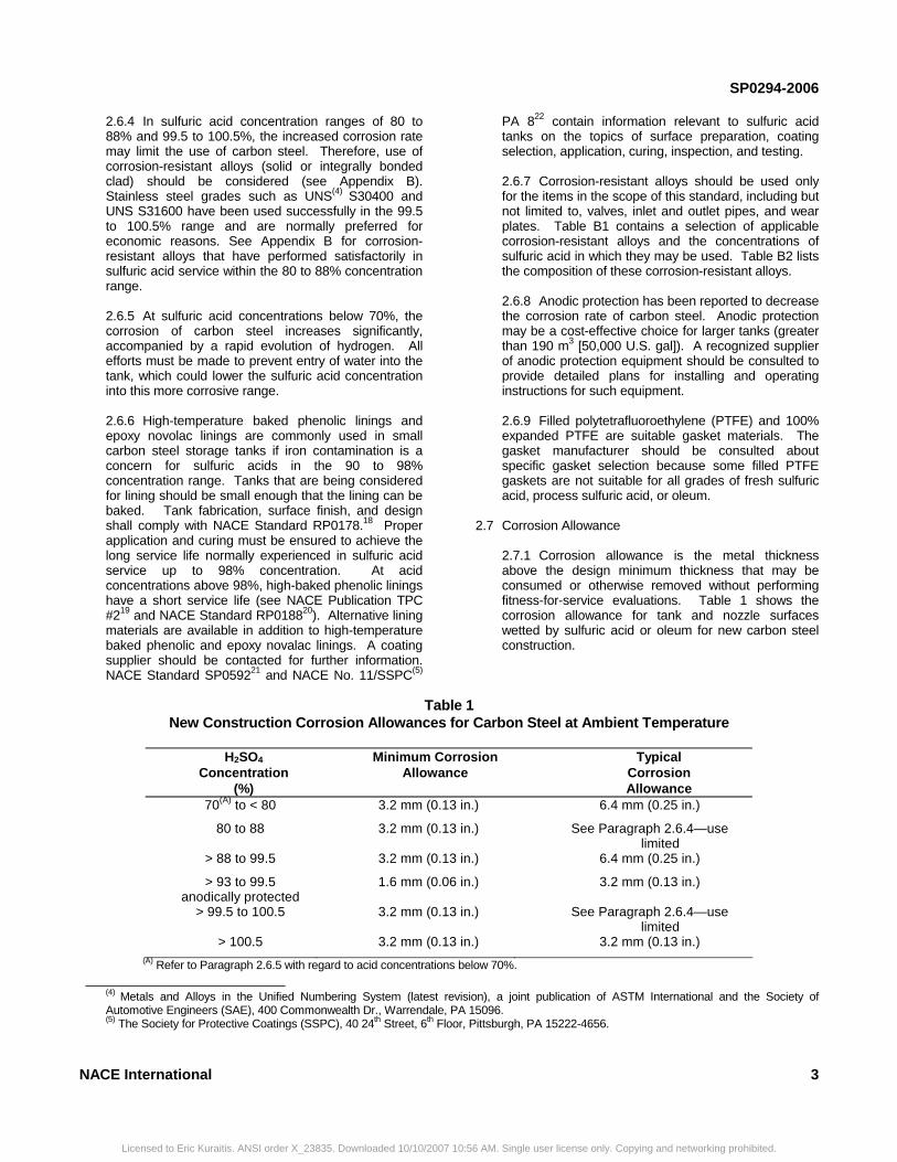
2.7.1 Corrosion allowance is the metal thickness above the design minimum thickness that may be consumed or otherwise removed without performing fitness-for-service evaluations. Table 1 shows the corrosion allowance for tank and nozzle surfaces wetted by sulfuric acid or oleum for new carbon steel construction.
Table 1 New Construction Corrosion Allowances for Carbon Steel at Ambient Temperature
H2SO4
Concentration (%)
Minimum Corrosion Allowance
Typical Corrosion Allowance
70(A) to < 80 3.2 mm (0.13 in.) 6.4 mm (0.25 in.)
80 to 88 3.2 mm (0.13 in.) See Paragraph 2.6.4—use limited
> 88 to 99.5 3.2 mm (0.13 in.) 6.4 mm (0.25 in.)
> 93 to 99.5 anodically protected
1.6 mm (0.06 in.) 3.2 mm (0.13 in.)
> 99.5 to 100.5 3.2 mm (0.13 in.) See Paragraph 2.6.4—use limited
> 100.5 3.2 mm (0.13 in.) 3.2 mm (0.13 in.) (A) Refer to Paragraph 2.6.5 with regard to acid concentrations below 70%.
___________________________ (4) Metals and Alloys in the Unified Numbering System (latest revision), a joint publication of ASTM International and the Society of Automotive Engineers (SAE), 400 Commonwealth Dr., Warrendale, PA 15096. (5) The Society for Protective Coatings (SSPC), 40 24th Street, 6th Floor, Pittsburgh, PA 15222-4656.
Licensed to Eric Kuraitis. ANSI order X_23835. Downloaded 10/10/2007 10:56 AM. Single user license only. Copying and networking prohibited.
SP0294-2006
The corrosion allowance shall adequately address the concentration, temperature (normal and excursion), and design life. Figure B1 provides a reference point for corrosion in fresh, stagnant sulfuric acid. The corrosion rate will be greatly accelerated under flowing, turbulent conditions. A number of other factors influence specification of the corrosion allowance. For example, at a given temperature and acid concentration, the corrosion rate depends on the amount of impurities in the acid and the flow conditions adjacent to the steel surface (acid movement in the tank); therefore, data found in the literature can only serve as a guideline. If the corrosion rate is expected to exceed 0.25 mm/y (10 mpy), a materials engineer should be consulted when selecting materials and specifying the corrosion allowance. Because impurities can lead to accelerated corrosion, a materials engineer should be consulted if dealing with contaminated acid or acids of various concentrations stored in the same tank (see Paragraph 1.6). 2.7.2 If a baked phenolic lining or anodic protection is used for internal protection, the corrosion allowance may be reduced. Baked phenolic linings isolate the metal from the acid, thereby preventing corrosion of the steel so long as the lining is undamaged. Using baked phenolic linings to reduce the corrosion allowance assumes that the coating meets the requirement of NACE Standard RP0592 of less than 1 holiday/10 m2 (1 holiday/100 ft2). 2.7.3 Corrosion test coupons installed in critical tank locations can provide valuable quantitative data on types of attack prevailing in the specific locations at which the coupons are installed. Electrically isolated and unisolated corrosion coupons are valuable in evaluating the performance of anodic protection systems. 2.7.4 Acid tanks handling 93 to 99.5% sulfuric acid expected to run at low levels may use 3.2 mm (0.13 in.) corrosion allowance for the shell courses normally above the liquid level. 2.7.5 Additional information about the roof corrosion allowance is provided in Paragraph 3.7.4.
2.8 Corrosion Phenomena of Unlined Carbon Steel Tanks
The service life of sulfuric acid tanks may be reduced considerably by internal and external corrosion phenomena.
2.8.1 Internal Corrosion The corrosion resistance of carbon steel contacted by sulfuric acid results from the protective iron sulfate film formed during the initial contact period. Any service condition causing a deterioration of the protective film is likely to lead to accelerated corrosion. Examples of deteriorating conditions are high flow velocities, acid dilution, or excessive temperatures. The following types of phenomena are chiefly responsible for
4
Licensed to Eric Kuraitis. ANSI order X_23835. Downloaded 10/10/2007 10:56 A
accelerated corrosion of carbon steel in sulfuric acid service:
2.8.1.1 Dilute sulfuric acid causes rapid attack of carbon steel. Dilute acid can be formed by absorption of moisture from the outside air, entry of rainwater, or improper cleaning. Entry of moisture from the outside should be controlled by proper venting and by minimizing air movement caused by natural convection. Taking measures to dry the air entering the tank reduces the risk of sulfuric acid dilution. Desiccant systems used for drying incoming air shall be properly maintained to ensure that vents are not inadvertently obstructed with desiccant. Vent obstruction can result in serious damage to a tank. In geographic locations where high humidity can create problems, a dry nitrogen or dry air pad (also known as a blanket) should be considered. 2.8.1.2 One type of preferential weld attack is attributed to acid retained in welding flaws. Examples of welding flaws include (but are not limited to) arc strikes, pits, gouges, and undercut. The acid retained in the welding flaws can be subsequently diluted by contact with moist air. The dilute acid can cause accelerated corrosion. To remove such flaws, the weld should be lightly ground (see Paragraph 4.2.2) and repaired if necessary. 2.8.1.3 Mill scale left on the steel surface promotes corrosion. Mill scale should be removed from the steel surface to be exposed to the sulfuric acid before placing the tank in service. Grit blasting to remove mill scale should be considered. 2.8.1.4 Hydrogen grooving may occur especially along the top at the 12 o’clock position of horizontal manways and nozzles, in the top half of horizontal manways, horizontal side nozzles, horizontal tanks, inwardly inclined walls, horizontal or inclined piping, or in horizontal welds with excess reinforcement. Hydrogen bubbles form as a result of corrosion; as the bubbles rise, they remove the protective film, exposing fresh steel surface and thereby initiating high rates of localized corrosion. In areas of the tank that are susceptible to hydrogen grooving, corrosion-resistant alloys should be used instead of carbon steel (see Appendix B, Table B1 for corrosion-resistant alloys; Appendix C, Figures C1 and C2 for illustrations of recommended design; and Paragraphs 3.5.2 and 3.5.3 for additional information). 2.8.1.5 Inlet and outlet velocity-accelerated corrosion (or erosion-corrosion) can lead to extensive attack. Measures to prevent this type of attack include appropriate design illustrated in
NACE International
M. Single user license only. Copying and networking prohibited.
SP0294-2006
Appendix C and suitable selection of corrosion-resistant alloys from Table B1.
2.8.1.5.1 Acid velocity is an important consideration. Velocity-accelerated corrosion may result if acid velocity exceeds 0.9 m/s (3 ft/s) on carbon steel and 1.8 m/s (6.0 ft/s) on stainless steel. Refer to NACE Standard RP0391 for further information on velocity limitations for specific materials. 2.8.1.5.2 If the top inlet nozzle is located too close to the tank side wall, turbulence in the acid can result in excessive corrosion, severe wall thinning, and loss of containment (see Paragraph 3.2.2). The top inlet nozzle should be at least 1.8 m (6.0 ft) from the tank side wall, if the tank size permits. The top inlet nozzle should incorporate a dip tube.
2.8.1.6 Corrosion products can wedge apart carbon steel components if acid gets between components. For example, wear plates can be wedged apart if acid gets between the wear plate and tank bottom.
2.8.1.7 Localized corrosion can result from an improperly designed, installed, and operated external heating system. See Paragragh 3.9 for further considerations about external heating systems.
2.8.1.8 A deformed compression ring detail (see Figure C7, Type III) can trap acid.
2.8.2 External Corrosion For external corrosion of carbon steel tanks, consideration should be given to the following areas:
NACE International
_______________________________________
Section 3: Tank De 3.1 Support
3.1.1 The following loads shall be in the design basis of supporting structure for all tanks:
3.1.1.1 Static loads during erection plus expected wind, ice, and snow loads during the erection.
3.1.1.2 Static loads during hydrotesting plus 25% of the wind, ice, and snow loads. 3.1.1.3 Static loads during operation (including the load due to fireproofing) plus applicable combinations of wind, ice, snow, and earthquake loads.
Licensed to Eric Kuraitis. ANSI order X_23835. Downloaded 10/10/2007 10:5
2.8.2.1 If the tank foundation and the area drainage are not properly designed and installed to prevent rainwater or ground water from wetting the underside of the tank floor, localized corrosive attack may occur. 2.8.2.2 If the tank is supported on steel I-beams (also called piers or dunnage), rainwater or acid spillage may collect between the I-beam surface and the tank bottom, resulting in local crevice corrosion of the tank bottom. I-beam size is typically selected based on tank loads. However, the next larger I-beam size should be selected to provide corrosion allowance for the I-beams. Application of a coating should also be considered as a method to reduce I-beam corrosion. 2.8.2.3 Insulated tanks that do not have a suitable surface protection system can corrode under the insulation due to ingress of moisture. Roof and shell attachments, insulation support rings, nozzles, manways, and shell-to-bottom joints are highly susceptible to this type of attack because of water and scale retention. See NACE Standard RP019823 for further information. 2.8.2.4 External corrosion of the roof can occur due to water pooling at structural support attachments, lap-welded roof plates, and deformed roof-to-shell compression ring angle (water can be trapped on the external portion of the Figure C7, Type III roof detail if this is deformed).
2.9 External Coating White coatings should be applied to external surfaces of uninsulated tanks to minimize radiant heating from the sun and keep the metal temperature as low as possible (see considerations in Paragraph 1.3).
5
_________________________________
sign Details
3.1.1.4 Loads resulting from the expansion and contraction of the tank due to internal pressure and temperature changes.
3.1.1.5 Loads from differential settlement across the supporting structures and foundations. Questions about support and foundations should be reviewed with an experienced civil engineer. 3.1.1.6 Static and dynamic loads during maintenance and operations.
3.1.2 Connecting pipes shall be of sufficient flexibility to avoid imposing excessive stress on the tank nozzles and associated piping as a result of tank movement.
6 AM. Single user license only. Copying and networking prohibited.
SP0294-2006
6 NACE International
3.1.3 Horizontal tanks (see Figure C3) shall be provided with steel saddles and/or concrete supports.(6)
3.1.3.1 Two or more piers shall be used to support a horizontal tank. 3.1.3.2 Consideration shall be given to the placement of supports to obtain the most desirable stress distribution in the tank shell. 3.1.3.3 The shape of the saddles shall conform to the fabricated shape of the tank or to the steel pad attached to the tank. 3.1.3.4 Doublers or reinforcing pads (repads) shall be installed between the tank and support. The repad shall be continuously welded to the tank shell after any free moisture is removed from under the plates. A threaded weep hole shall be provided at the low point of each plate; the weep hole shall be plugged with silicone grease to prevent the ingress of moisture. The doublers or repads shall extend beyond the limits of the supporting saddles to aid in distributing the support loads. The thickness of doublers or repad plates shall not be included in calculating the stress at the horn of the saddle.
3.1.4 For vertical tanks (see Figure C4), one of the two alternatives presented in Paragraphs 3.1.4.1 and 3.1.4.2 should be used, depending on tank diameter.
3.1.4.1 For tanks up to 12 m (40 ft) in diameter, there are two options for tank support. (a) Tanks may be supported on a raised, reinforced concrete slab foundation that is sloped and grooved to drain any water or leakage. (b) Tanks may be supported on steel I-beams for improved leak detection. The beams are frequently set on concrete piers (see Paragraph 2.8.2.2). Users should be aware that supporting a tank on beams could contribute to tank contents freezing, and insulating the floor would negate the leak detection feature. 3.1.4.2 For larger tanks, a concrete ring wall foundation with compacted granular fill and clean, washed sand topping may be used. Larger tanks may be installed on dunnage (steel beams). It may be more economical to use compacted granular fill with clean, washed sand instead of installing the tank on dunnage. 3.1.4.3 For tanks on concrete foundations, a suitable skirt may be considered to prevent water from running under the bottom plate.
3.1.4.4 Caulking between the tank bottom and foundation can interfere with drainage. Any such caulking must be carefully designed and applied to avoid external corrosion of the tank.
3.2 Inlet
3.2.1 Tanks shall be fitted with a top inlet nozzle (see Figures C6a and C6b) protruding at least 150 mm (6.0 in.) into the tank if a dip tube is not used. If a dip tube is used, the top inlet nozzle may protrude only 25 mm (1.0 in) into the tank. 3.2.2 For vertical tanks, the top inlet nozzle should be as close to the center of the tank roof (see Figure C4) as practical to reduce side wall attack (see Figure C5). For all tanks less than 6 m (20 ft) in diameter, the top inlet nozzle should be placed as close as possible to the vent in the center of the tank roof. The top inlet nozzle should be at least 1.8 m (6.0 ft) away from the side wall, if tank diameter permits. The top inlet nozzle may include a dip tube. If a dip tube is used, it must be supported by guides attached to the shell (see Figure C4) or a bracket welded to the floor. The dip tube should be located as far away as practical from the side wall, fitted to within approximately 1 m (3 ft) of the bottom (ensure that there is a wear plate on the tank bottom; see Figure C1), and the dip tube should contain a siphon break hole pointing toward the tank center (see Figure C6a). 3.2.3 Velocity criteria in NACE Standard RP0391 shall be considered when sizing the inlet (also see Paragraph 2.8.1.5.1). 3.2.4 Corrosion-resistant alloy construction should be considered for inlets on new construction or retrofit construction. 3.2.5 Alternatively, a 76-mm (3.0-in.) tubular guide for the dip tube with the guide welded to the tank floor may be used.
3.3 Outlet
3.3.1 Tanks may have a bottom or side outlet (see Figures C1, C4, C8, and C9). 3.3.2 Internal plug valves are sometimes chosen for sulfuric acid tanks with the intent of positive shut-off capability regardless of internal corrosion. They also are not subject to failure from external damage. However, experience has shown that internal plug valves are often unreliable in long-term service. The following measures should be taken when using internal plug valves:
__________________________________________
(6) The design of horizontal tanks supported by saddles or supports shall provide a safety margin equal to or greater than that provided by the L.P. Zick Method.24
Licensed to Eric Kuraitis. ANSI order X_23835. Downloaded 10/10/2007 10:56 AM. Single user license only. Copying and networking prohibited.
SP0294-2006
NACE International 7
3.3.2.1 Tanks should be designed with at least two outlets if internal plug valves are to be used. This will minimize problems resulting from a valve failing in the closed position. verify the operability and tightness of shut-off capability of these valves. 3.3.2.2 To ensure a tight shut-off, the design should include a second shut-off valve in the piping downstream from the internal plug valve. 3.3.2.3 Scheduled periodic testing of internal plug valve operation should be performed to verify the operability and tightness of shut-off capability of these valves. 3.3.2.4 End users may address the limitations of internal plug valves in their safety procedures and incorporate additional designs to compensate for a leaking valve.
3.3.3 The external outlet valve should be fitted as close to the tank as practical. If it is necessary to provide an outlet elbow before the valve, it shall be of long-radius type with an extra-heavy wall. The outlet and elbow should have the same inside diameter. As a guideline, the wall thickness of the elbow should be a minimum of 3.2 mm (0.13 in.) greater than the piping installed downstream from the outlet valve (see Figure C4). Corrosion-resistant alloy construction is often used for piping and elbows between the tank outlet nozzle and the first valve. Cast iron shall not be used for piping between a tank nozzle and the first valve below the liquid level. 3.3.4 Velocity criteria in NACE Standard RP0391 shall be considered when sizing the outlet (also see Paragraph 2.8.1.5.1). 3.3.5 Outlet piping should be protected from mechanical damage that could impact the tank system integrity. 3.3.6 Outlet nozzles, piping, and valves should be high quality. Suitable corrosion-resistant alloys listed in Table B1 should be considered for all nozzles, piping, and valves below the liquid level.
3.4 Vents
3.4.1 Vents should be mounted near the high point in the center of the tank to prevent hydrogen buildup and thereby avoid any potential safety problem with a hydrogen buildup. 3.4.2 Vents should have drip lips to keep any moisture drips away from the tank roof or side wall (see Figure C6b). Moisture drips into the center of the tank typically dissolve in the acid before contacting the side wall. Larger tanks have less of a problem than smaller
day tanks that change level more often and have vents closer to the side wall. 3.4.3 Consideration must be given to the advantages and disadvantages of desiccator vents compared with open vents. 3.4.4 Vents shall be designed to minimize moisture ingress. 3.4.5 A nitrogen pad (blanket) with conservation venting for environmental protection and moisture ingress prevention should be considered. 3.4.6 In the case of tanks containing oleum, off-gases must be dealt with according to applicable regulations. 3.4.7 Vents should be inspected periodically to ensure that they are not blocked (see also Paragraphs 2.8.1.1 and 5.7.3.3 (i). 3.4.8 Vent design for oleum tanks has a very different basis from the vent design for concentrated sulfuric acid tanks. These differences must be accounted for in the respective vent designs. Oleum vent system design and materials are not part of this standard.
3.5 Manways and Side Nozzles
3.5.1 Suitable access manways shall be provided (see Figure C2; also see Figure C4 for vertical tanks and Figure C3 for horizontal tanks). 3.5.2 In vertical tanks, manways and side nozzles shall be flush with the shell internal surface on the bottom 180° and should have a minimum 25-mm (1.0-in.) visor on the top 180° to force any hydrogen bubbles away from the side wall (see Figures C1 and C2).
3.5.3 Solid corrosion-resistant alloy or corrosion-resistant alloy-clad steel side nozzles and manways should be used. There has been mixed performance with loose liners(7) in sulfuric acid service. For side nozzles and manways, a corrosion-resistant alloy lining, weld overlay, or clad plate projecting a minimum of 25 mm (1.0 in.) into the tank may be provided for protection against hydrogen grooving (see Figures C1 and C2, and Paragraph 2.8.1.4). All horizontal side nozzles shall be flush with the tank steel on the bottom 180°. For corrosion-resistant alloy-clad steel and weld-overlaid carbon steel nozzles, the edge of the nozzle projecting inside the tank should be overlaid for corrosion protection (to prevent end-grain attack). 3.5.4 Lap-joint and slip-on flanges may be used for corrosion-resistant alloy nozzles, but long weld neck flanges are preferred for nozzles smaller than 150 mm (6.0 in.) in diameter.
__________________________________________
(7)The term loose liner refers to an alloy plate attached to the carbon steel by a limited number of seal welds and/or plug welds.
Licensed to Eric Kuraitis. ANSI order X_23835. Downloaded 10/10/2007 10:56 AM. Single user license only. Copying and networking prohibited.
SP0294-2006 3.6 Wear Plate
3.6.1 For vertical tanks, a wear plate of sufficient size and thickness shall be seal welded to the bottom of the tank directly beneath the inlet and outlet pipes (see Figures C1 and C4). The perimeter of the wear plate shall be completely welded to avoid crevices. 3.6.2 A vent hole is part of the common installation practice for wear pads to prevent porosity of the seal weld. After the entire perimeter of the wear plate has been seal welded, the vent hole shall be welded closed or a threaded plug shall be installed in the vent hole and then the threaded plug shall be seal welded.
3.7 Roof of Vertical Tanks
3.7.1 The roof should be sloped and self-supporting. Roof support girders should be installed externally. 3.7.2 For large-diameter tanks, internal support columns are acceptable. Adequate corrosion allowance shall be provided for the internal support columns. Tanks with fuming acid (oleum service) shall have the appropriate corrosion allowance including all components in the vapor area. Open section columns are preferred over tubular sections for safety reasons during internal inspection. 3.7.3 A tank designed with a roof-to-shell connection similar to Type III in Figure C7 may be used to ensure that a rupture initiates at the top connection if the tank is overpressurized. See API 650 for frangible roof design. 3.7.4 Consideration should be given to adding a corrosion allowance of 3.2 to 4.8 mm (0.13 to 0.19 in.) to the roof plate.
3.8 Level Control 3.8.1 Tanks shall be fitted with a suitable level indicator and overflow protection. Special care must be taken to minimize moisture ingress from the atmosphere. Consideration should be given to installing an alarm with a high signal, a high-high signal, and an automatic shutoff to prevent overflow. 3.8.2 Oleum overflow protection may also include a hydraulic seal with suitable sealing fluid (consult the oleum supplier). 3.8.3 Consideration should be given to conservation vents because no sealing fluid is required. Side outlet overflow nozzles may be considered. Vents that protrude into the tank should be oriented to keep the moisture away from the tank wall.
3.9 Heating Systems
3.9.1 In areas where acid-freezing temperatures are possible (see Figure A2), a suitable heating system and proper insulation should be included in the tank design. Similarly for piping, if there is a risk of acid freezing, a suitable heat-tracing design should be used. Electrical heat tracing requires designing for the possibility of power loss and needs for thawing lines. 3.9.2 Heating the tank contents by circulation through an external heater has been used for warming both acid and oleum. Insulation, without tracing, has been used to prevent freezing of 98 to 100% acid and some concentrations of oleum. 3.9.3 Tank insulation combined with noncontact low-pressure steam coils under the tank has been used for oleum service. Electrical tracing, with controlled temperature to keep the metal below the corrosion design temperature,(8) has been used for the storage tank system as defined in Paragraph 1.8. If not properly designed, monitored, and controlled, external heating coils can lead to localized corrosion. 3.9.4 Heating systems for tanks shall be designed to ensure that operation is below the corrosion design temperature. This is especially important for the tank metal near the heaters. To minimize local corrosion, care should be taken to discharge steam traps away from the tank wall and bottom.
3.9.5 Acid temperature affects the tank inspection interval. Often, the inspection interval is based on the corrosion rate related to the acid inlet temperature. The corrosion rate can increase sharply if the heating system elevates the bulk temperature above the average acid inlet temperature. The bulk acid temperature shall be monitored when using heating systems. The inspection interval may require adjustment if the bulk acid temperature exceeds the inlet acid temperature. The metal temperature near the heater elements also should be monitored to determine whether the inspection interval has to be adjusted. 3.9.6 When insulation is used, the tanks may be protected with a suitable coating system under the insulation. The use of insulation materials suitable to prevent retention of moisture (e.g., of the perlite-silicate or cellular glass type) should be considered. See NACE Standard RP0198 for further information.
3.10 Bottom Plate Thickness
3.10.1 For vertical tanks, the minimum thickness of the bottom plate shall be 13 mm (0.50 in.), including corrosion allowance and taking into consideration Paragraphs 2.5 and 2.7.
__________________________________________
(8) Specifying the corrosion allowance should account for the influence of temperature, concentration, velocity, normal process conditions, excursion conditions, risk tolerance, economic considerations, and other factors. The temperature used to determine the corrosion allowance is called the corrosion design temperature.
8 NACE International
Licensed to Eric Kuraitis. ANSI order X_23835. Downloaded 10/10/2007 10:56 AM. Single user license only. Copying and networking prohibited.
SP0294-2006
NACE International
________________________________________________________________________
Licensed to Eric Kuraitis. ANSI orde
Section 4: Fabrication and Erection
4.1 Verification Procedure The user/fabricator should have a positive material identification (PMI) procedure to verify that the chemical composition of each component is consistent with the specified material. The user/fabricator may choose to use the relevant sections in API RP 57825 for this purpose. 4.2 Surface Preparation4.2.1 All areas to be welded should be cleaned and prepared in accordance with the applicable standards. 4.2.2 Before the tank is placed in service, all mill scale, weld slag, and weld spatter should be removed from the internal surface by appropriate methods. 4.2.3 All clips for scaffolds, bulldogs, rigging, and all other construction and erection attachments must be removed prior to putting the tank in service. Surrounding areas must be ground smooth and inspected. 4.2.4 Care must be taken so that grinding does not reduce the parent metal to less than the minimum acceptable wall thickness.
4.3 Welding Requirements
4.3.1 Weld procedures and filler materials shall comply with applicable codes and governing standards. 4.3.2 All butt welds shall be full-penetration with 100% fusion through the full thickness of metal. When practical, double-welded butt joints shall be used. See Appendix D, Section D3 for weld acceptance criteria. 4.3.3 With regard to surfaces to be coated or lined, weld surface finish shall be in accordance with NACE Standard RP0178 (unless the end user has surface preparation standards more stringent than NACE Standard RP0178). 4.3.4 Lap welds should be confined to roof construction of vertical tanks (see Paragraph 4.4.3). The minimum thickness of lap welds shall be the thickness of the thinnest plate joined. For oleum tanks, internal lap joints should be completely seal welded (not skip welded) to avoid vapor space crevices and minimize the potential for roof leaks. Tanks with 99.5% and lower acid concentration do not have a significant vapor pressure and open laps on the inside are not a major issue if they are designed to drain.
4.4 Specific Components
r X_23835. Downloaded 10/10/2007 1
4.4.1 All nozzle neck and manway neck welds to the shell shall be full-penetration welds welded from both sides. 4.4.2 The welds for vertical tank bottoms shall be butt welds. Lap welding shall not be used for bottom fabrication. 4.4.3 Roofs of vertical tanks may be butt or lap welded (see Paragraph 4.3.4). 4.4.4 The shell-to-bottom joint shall be a full-penetration weld and welded from both sides with reinforcing fillets.
4.5 Internal Welds Below Liquid Level
4.5.1 All welds shall be full-penetration, except for components with low strength requirements such as slip-on flanges, nozzle liners, and reinforcement pads. Slip-on or socket welds should not be used unless special precaution is taken for localized washout effect. Special precautions include, but are not limited to, increasing thickness, reducing inspection intervals, and applying weld buildup. 4.5.2 All manual full-penetration welds greater than 6.4 mm (0.25 in.) shall have at least three layers of weld metal (weld passes) to reduce the risk of leakage. Welds should be thoroughly cleaned between passes to avoid slag entrapment (see Paragraph 4.2.1).
4.6 Nondestructive Inspection for New Construction
4.6.1 API 620 and API 650 contain additional considerations for fabrication inspection documentation. Some of the considerations in the API standards are different from the considerations needed for sulfuric acid storage tanks. See Section 5 for more information on inspection intervals of in-service tanks. Interpretations of the codes and standards for new construction should be discussed with an experienced pressure vessel/tank engineer, materials engineer, and/or a knowledgeable person who has experience with sulfuric acid storage tanks. 4.6.2 A certified inspection shall be performed and test results shall be documented before placing the tank in service (see Section 5). The inspector shall have an API 653 certification for vertical tanks and an API 510 or NB(9) NBIC (also called National Boiler Inspection Code Publication NB-23)26 certification for horizontal tanks.
___________________________ (9)The National Board of Boiler and Pressure Vessel Inspectors (NB), 1055 Crupper Ave., Columbus, OH 43229.
9
0:56 AM. Single user license only. Copying and networking prohibited.
SP0294-2006
1
4.6.3 Techniques and documentation of inspection shall meet the requirements of the applicable code or standard (see Paragraph 4.6.1), this standard, and the purchase specification. 4.6.4 Results of inspections shall comply with requirements of the applicable code or standard (see Paragraph 4.7.1). 4.6.5 For future reference, the material thickness of the tank should be measured in identifiable locations such as near appurtenances (inlets, outlets, nozzles, and manways). The measurements on the shell just below the appurtenance attachment and just above the appurtenance attachment) should especially be compared. The measurements should be taken to serve as reference data for comparison with future thickness measurements. See Paragraphs 5.5.3 and 5.5.4 for further recommendations on thickness measurement locations. 4.6.6 The internal surface of all welds below the liquid level shall be tested by wet fluorescent magnetic particle (high sensitivity), magnetic particle (intermediate sensitivity), or liquid penetrant inspection (least sensitive of the inspection techniques listed in this paragraph) after fabrication and before placing the tank in service.
0
________________________________________
Licensed to Eric Kuraitis. ANSI order X_23835. Downloaded 10/10/2007 10:56
4.6.7 If the tank bottom is welded in an elevated condition, 100% radiographic testing should be performed. Acceptance guidelines are provided in Appendix D. 4.6.8 One-hundred percent of all vertical seam welds of the bottom two courses (rings) should be tested by radiography. For vertical seams of all other rings, at least one random test shall be performed. All horizontal-vertical weld intersections of the shell shall be radiographed. Acceptance guidelines are provided in Appendix D. Consideration should be given to leak testing welds with a vacuum box. Paragraph 3.10 contains additional information on vertical weld joint efficiencies. 4.6.9 Defect repairs and reinspections shall be in accordance with the original code or standard of construction, this standard, and the purchasing specification. The location of any indication repairs should be documented for future reference. 4.6.10 Random hardness tests should be performed on major tank seams on the inside surface and on nozzle welds by agreement between the purchaser and vendor (see Paragraph 2.6.2). To address concerns about adequate preheating, repair welds should have hardness measurements.
________________________________
Section 5: Inspection and Maintenance
5.1 Scope and Inspection Interval5.1.1 This section provides guidelines to ensure that storage tanks containing concentrated sulfuric acid and oleum are maintained in a safe condition. The user has discretion for inspection intervals and details. The following are considered to be minimum requirements. 5.1.2 General Inspection Procedures and Personnel Qualification
5.1.2.1 All carbon steel tanks shall be subjected to four forms of inspection that correspond with API 653 inspection guidelines. The requirements in this standard shall be followed in addition to the API 653 requirements. These inspections are described as: • Routine in-service inspection—see Paragraph
5.4.
• External visual inspection—see Paragraph 5.5.
• External ultrasonic thickness (UT) inspection—see Paragraph 5.6.
• Internal inspection—see Paragraph 5.7.
AM
Because of the complex nature of sulfuric acid corrosion, the external visual, external UT, and internal inspections shall be supervised by an API 653 authorized inspector (for vertical tanks), an API 510 authorized inspector (for horizontal and API 620 tanks), or an NBIC authorized inspector (for horizontal tanks) experienced in sulfuric acid tank inspection. If the inspector is not experienced in sulfuric acid tank inspection, the inspector shall consult a materials engineer or an inspector with such experience. A detailed checklist, prepared prior to the inspection, should guide the inspection program. In some cases the inspector may need to consult with knowledgeable and experienced materials, civil, mechanical, inspection, and process engineers. The following discussion on inspection intervals assumes the tank is made from carbon steel. 5.1.2.2 Tanks made totally from stainless steel should be inspected in accordance with API 653, API 510, and/or NBIC requirements.
5.1.3 Before placing a new or used tank in sulfuric acid or oleum service, the operating company must certify its fitness for service. If the tank service is being changed to sulfuric acid or oleum service from a previous service, it shall be evaluated using API 653 or
NACE International
. Single user license only. Copying and networking prohibited.
SP0294-2006
API 510 and this standard. The initial inspection interval shall be established based on known corrosion rates in similar service and the guidance of this standard, but should not exceed the intervals summarized in Table 2 and discussed below. This interval should be reevaluated if the tank has been subjected to operational abuse or mishaps. After each external UT inspection the tank must receive a fitness-for-service engineering evaluation by knowledgeable engineers and qualified inspectors, and the interval until the next internal inspection and thickness testing should be evaluated. An engineering review of the operating history, available corrosion allowance, external visual examinations, and inspection history may indicate that the maximum inspection intervals described below should be decreased.
5.1.3.1 New or used tanks in sulfuric acid service not designed, fabricated, and inspected in accordance with the minimum requirements of this standard shall receive external visual and UT inspections in accordance with Paragraphs 5.5 and 5.6 within 2 years after initially being placed in sulfuric acid service, and an internal inspection in accordance with Paragraph 5.7 within 4 years after being placed in sulfuric acid service. Linear UT scans(10) shall be used if bathtub-ring corrosion or erosion-corrosion is suspected. The results of the external visual and UT inspections in accordance with Paragraphs 5.5 and 5.6 may indicate that internal inspection should be performed sooner. Tanks experiencing leakage should be inspected internally and repaired within 3 months after the leakage was first noticed and mitigated.
5.1.3.2 New or used tanks in sulfuric acid service designed, fabricated, and inspected in accordance with this standard shall receive external visual and UT inspections in accordance with Paragraphs 5.5 and 5.6 within 3 years after being placed in service, and an internal inspection in accordance with Paragraph 5.7 within 6 years after being placed in service. The internal inspection interval may be based on the results of a RBI evaluation. The RBI internal inspection interval may differ from the internal inspection interval set forth in this paragraph and Table 2. Linear UT scans shall be used if bathtub-ring corrosion or erosion-corrosion is suspected. The results of the external visual and UT inspections in accordance with Paragraphs 5.5 and 5.6 may indicate the internal inspection should be performed sooner. Tanks
NACE International
___________________________
Licensed to Eric Kuraitis. ANSI order X_23835. Downloaded 10/10/2007 10:56 A
experiencing leakage should be inspected internally and repaired within 3 months after leakage was first discovered and mitigated. 5.1.3.3 New or used tanks for oleum service not designed, fabricated, and inspected in accordance with this standard shall receive external visual and UT inspections in accordance with Paragraphs 5.5 and 5.6 within 3 years after being place in service and an internal inspection in accordance with Paragraph 5.7 within 6 years after being placed in service. The results of the external visual and UT inspections in accordance with Paragraphs 5.5 and 5.6 may indicate that the internal inspection should be performed sooner. Tanks experiencing leakage from the liquid phase shall be taken out of service and repaired as soon as is practical to do so, but not more than 1 month after the leakage was first discovered and mitigated. 5.1.3.4 New or used tanks for oleum service designed, fabricated, and inspected in accordance with this standard shall receive external visual and UT inspections in accordance with Paragraphs 5.5 and 5.6 within 3 years after being placed in service and every 3 years thereafter. An internal inspection in accordance with Paragraph 5.7 shall be performed within 6 years after being placed in service. The internal inspection interval may be based on the results of a RBI evaluation. The RBI internal inspection interval may differ from the internal inspection interval set forth in this paragraph and Table 2. The results of the routine in-service inspections in accordance with Paragraph 5.4 and external visual and UT inspections in accordance with Paragraphs 5.5 and 5.6 may indicate that the internal inspection should be performed sooner. Tanks experiencing leakage shall be internally inspected and repaired as soon as is practical to do so, but not more than 1 month after the leakage was first discovered and mitigated.
5.1.4 After the first internal inspection of sulfuric acid or oleum tanks in accordance with Paragraph 5.1.3 have been completed, the dates for the next external and internal inspections shall be determined by an API 653 authorized inspector (API 510 or NBIC authorized inspector for horizontal tanks and API 620 tanks). A condition-based or risk-based approach, in accordance with API 510 or API 653, as appropriate, should be used to determine the next inspection intervals.
(10) Linear UT scans—Linear ultrasonic thickness scans are much more likely to detect bathtub-ring corrosion and local erosion-corrosion than spot UT measurements. UT scans are continuous thickness measurements (B-scans) along a straight path conducted manually or with a magnetic crawler. At least four vertical scans, each spaced 90 degrees around the tank circumference, and two circumferential scans for each plate course within 3 m (10 ft) of the inlet or dip pipe or within 1 m (3 ft) of the bubbler shall be made on vertical tanks. The vertical scans should start as close to the tank bottom as possible and end just below the roof. Horizontal tanks shall have at least three circumferential scans equally spaced around the side walls of the tank and vertical scans at both heads starting from the 6 o'clock position to the 12 o'clock position. In addition, horizontal tanks shall have at least two horizontal scans on each side of the tank below the acid inlet nozzle; the location and length of these scans shall be such that side wall erosion-corrosion can be detected. Additional linear scans may be necessary depending on the tank design, operation, and the results of inspections and thickness measurements.
11
M. Single user license only. Copying and networking prohibited.
SP0294-2006
If condition-based inspection methods are used to determine the inspection intervals, the maximum intervals shall be as summarized in Table 3 and discussed below:• External UT inspection in accordance with Paragraph 5.6—3 years;
• Internal inspection in accordance with Paragraph
5.7—6 years.
12
Licensed to Eric Kuraitis. ANSI order X_23835. Downloaded 10/10/2007 10:5
If risk-based methodology is used to determine inspection intervals, as allowed in API 653 and API 510, and recommended by this standard, the maximum intervals shall be as summarized in Table 3 and discussed below:
• External UT inspection in accordance with
Paragraph 5.6—As proposed by the RBI model up to the API 653 maximum.
• Internal inspection in accordance with Paragraph 5.7—As proposed by the RBI model.
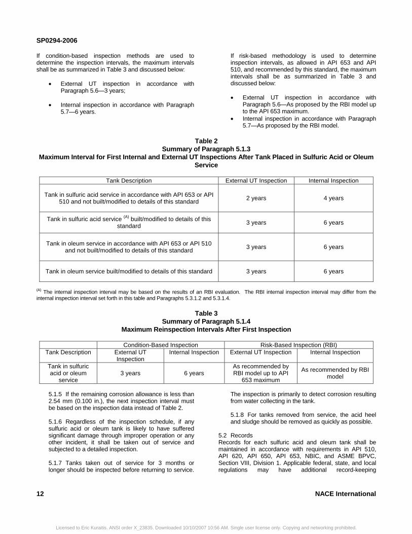
Table 2 Summary of Paragraph 5.1.3
Maximum Interval for First Internal and External UT Inspections After Tank Placed in Sulfuric Acid or Oleum Service
Tank Description External UT Inspection Internal Inspection
Tank in sulfuric acid service in accordance with API 653 or API
510 and not built/modified to details of this standard
2 years 4 years
Tank in sulfuric acid service (A) built/modified to details of this standard 3 years
6 years
Tank in oleum service in accordance with API 653 or API 510 and not built/modified to details of this standard
3 years
6 years
Tank in oleum service built/modified to details of this standard
3 years
6 years
(A) The internal inspection interval may be based on the results of an RBI evaluation. The RBI internal inspection interval may differ from the internal inspection interval set forth in this table and Paragraphs 5.3.1.2 and 5.3.1.4.
Table 3 Summary of Paragraph 5.1.4
Maximum Reinspection Intervals After First Inspection
Condition-Based Inspection Risk-Based Inspection (RBI) Tank Description External UT
Inspection Internal Inspection External UT Inspection Internal Inspection
Tank in sulfuric acid or oleum
service 3 years
6 years
As recommended by RBI model up to API
653 maximum
As recommended by RBI model
5.1.5 If the remaining corrosion allowance is less than 2.54 mm (0.100 in.), the next inspection interval must be based on the inspection data instead of Table 2. 5.1.6 Regardless of the inspection schedule, if any sulfuric acid or oleum tank is likely to have suffered significant damage through improper operation or any other incident, it shall be taken out of service and subjected to a detailed inspection. 5.1.7 Tanks taken out of service for 3 months or longer should be inspected before returning to service.
6
The inspection is primarily to detect corrosion resulting from water collecting in the tank. 5.1.8 For tanks removed from service, the acid heel and sludge should be removed as quickly as possible.
5.2 Records Records for each sulfuric acid and oleum tank shall be maintained in accordance with requirements in API 510, API 620, API 650, API 653, NBIC, and ASME BPVC, Section VIII, Division 1. Applicable federal, state, and local regulations may have additional record-keeping
NACE International
AM. Single user license only. Copying and networking prohibited.
SP0294-2006
requirements. At a minimum, documentation should include the following:(a) Tank description • Tank reference number • Tank size • Tank capacity • Year commissioned • Tank data sheet
(b) Tank design and construction details
• Drawing • Design calculations • Purchase specification • Materials specifications including linings, plates,
and welds • Minimum required thickness • Corrosion allowance • Original design scope and fabrication quality
control documentation (c) Components (all components up to and including first valve)
• Valves • Piping • Flange details • Gaskets, material of construction
(d) Tank contents
• Acid concentration and temperature conditions for which the tank was designed
• Actual acid concentration and temperature conditions
• Service history (e) Civil engineering details (e.g., support, soil) (f) Heating and insulation details, including protective coating if applicable (g) Venting system used and its design basis (h) Modifications to the original design concept (for example, a change in contained fluid to one of higher specific gravity could result in lowering the maximum allowable liquid level or reducing available corrosion allowance) (i) Inspection intervals and the scheduled maintenance program set by the provisions of this standard (j) Results of all inspections, maintenance, and repair work, including a written description for the scope of repairs
• Details of any incidents that have occurred (k) For lined tanks
• Date the lining was applied
NACE International
Licensed to Eric Kuraitis. ANSI order X_23835. Downloaded 10/10/2007 10
• Generic or proprietary name of the lining material used
• Identification of the applicator • Lining inspection records
5.3 Tank Cleaning
5.3.1 The following items should be considered when preparing a cleaning procedure for unlined carbon steel sulfuric acid tanks for internal inspection.
5.3.1.1 Empty the tank of sulfuric acid. 5.3.1.2 Verify that vapor phase conditions are not explosive before doing any hot work. Be aware that hydrogen, elemental sulfur, and hydrogen sulfide can be trapped in the sludge. Appropriate caution should be exercised when removing sludge. See Paragraph 1.6 for discussion of impurities in sulfuric acid. 5.3.1.3 Take the necessary precautions to ensure that the sludge is kept in suspension in the acid during acid removal. As much sludge as possible should be removed without introducing water (e.g., by using a vacuum truck). The sludge is easier to remove with the acid that remains in the tank. Sludge can harden if all the acid is removed prior to trying to remove the sludge. 5.3.1.4 Wash any remaining sludge through bottom outlets or sludge manways with copious quantities of inhibited water. To minimize corrosion and the buildup of a high concentration of hydrogen in the tank, dilute sulfuric acid must not be allowed to remain in the tank for any significant period. The tank metal temperature should be closely monitored to prevent personnel exposure to hot metal. Because hydrogen may be present, precautions must be taken to eliminate any kind of fire or spark near the tank when washing the tank interior. Cleaning contractors that specialize in rotating-head cleaning service may be commissioned. Also, vacuum trucks/equipment used to remove the sludge must not contain hydrocarbon sludge or organics that may react, sometimes violently, with sulfuric acid. 5.3.1.5 When the sludge and standing acid have been removed, the tank interior should be flushed with water and drained completely to eliminate residual sulfuric acid on the floors, shell, and roof. This must be done rapidly as corrosion rates of steel in dilute sulfuric acid can be as high as 6.0 mm (0.25 in.) per day. Water washing should continue until the pH of the residual liquid on the floor and shell is greater than 7. In some instances, the end user may want to perform a neutralizing wash with basic/alkali materials (pH >7). There are a number of ways to accomplish a neutralizing wash and each method has certain merits and considerations. Whether the end user
13
:56 AM. Single user license only. Copying and networking prohibited.
SP0294-2006
performs a water wash and/or neutralizing wash, he/she should use existing company tank cleaning procedures or develop a tank cleaning procedure with an experienced tank cleaning contractor. 5.3.1.6 Empty the tank and check for entry conditions (see Paragraph 6.5). 5.3.1.7 If necessary, grit blast the internal tank surfaces after cleaning to achieve a surface condition conducive to inspection. 5.3.1.8 Take preventive measures to prevent acid from being trapped for extended times in confined spaces such as between closed block valves. Hydrogen generated from corrosion of the trapped acid can rupture piping and valves; see NACE Standard RP0391 for more information. Note: Serious damage may occur if cleaning is carried out incorrectly.
5.3.2 The following modifications of the items outlined in Paragraph 5.3.1 should be employed when preparing for inspection of a sulfuric acid tank with a baked phenolic lining.
5.3.2.1 Great care must be taken to ensure that the tools used to clean the tank do not cause mechanical damage to the tank lining. Scraping or scouring tools must be used with caution. 5.3.2.2 Neutralizing rinses using alkaline chemicals should be conducted only after discussion with a materials engineer, the coating manufacturer, and/or the lining applicator.
5.3.3 Before beginning any work on the tank, the safety of the atmosphere in the tank shall be ensured. Safety experts shall be consulted for detailed procedures and requirements. Caution: Tanks or associated piping, connections, etc., shall not be allowed to remain in contact with dilute sulfuric acid for any significant period of time.
5.4 Routine In-Service Inspections Periodic external visual inspections shall be performed to check for external corrosion of the tank, supports, foundation, and components. In most plants, this inspection is carried out by operators in the plant area, but there may be storage facilities where special arrangements are necessary because of a lack of onsite personnel. In such cases, an external visual inspection should be scheduled at least once per week and documented. Refer to API 653. 5.5 External Visual Inspection
5.5.1 An external visual inspection shall be conducted, as applicable, in accordance with Paragraphs 5.1.3.1 to 5.1.3.4 (summarized in Tables 2 and 3). API 653
14
Licensed to Eric Kuraitis. ANSI order X_23835. Downloaded 10/10/2007 10:5
provides a useful external visual checklist. Inspection should be performed by an API 653, API 510, or NBIC authorized inspector. Previous inspection reports should be reviewed for any items that require additional emphasis. 5.5.2 Adapting the API 653 external inspection checklist for use with sulfuric acid storage tanks should be considered. For both horizontal and vertical tanks, external visual inspection should include the following: (a) Welds; (b) General shell condition, including coating and insulation. Check for signs of wet insulation. It may be necessary to remove additional insulation to determine the extent of corrosion; (c) Acid inlet and outlet, overflow nozzle, manways, and adjacent shell plates; (d) Piping up to the first valve, gaskets, flange bolting, and venting system (see Paragraph 1.8 for a definition of the storage tank system);
(e) UT measurement of piping up to the first valve, especially in areas with a potential for hydrogen grooving (see Paragraph 1.8 for a definition of the storage tank system); (f) Valves; (g) Heating systems; (h) Anodic protection system;
(i) Condition of foundation; and
(j) Roof-to-shell joints where there is potential for water pooling. If any of the above items of inspection show defects such as uniform or local corrosion or cracks, engineering evaluation and remedial action should be performed without delay. 5.5.3 All weep holes, especially those associated with repads (doublers), should be inspected for evidence of leakage. Weep holes on external components shall not be plugged. Silicon grease is commonly used to prevent water ingress into the weephole.
5.6 External UT Inspection
5.6.1 Previous reports should be reviewed for any items that require emphasis. 5.6.2 External UT inspections shall consist of UT measurements, emphasizing critical areas as specified in the following paragraphs. If horizontal (bathtub-ring) grooving is suspected, UT scanning should be used. The anodic protection system, if present, should also
NACE International
6 AM. Single user license only. Copying and networking prohibited.
SP0294-2006
be checked to ensure it is in working order. If the tank is insulated, the insulation shall be stripped in test areas. The inspector must ensure that the materials and corrosion allowance are appropriate for the sulfuric acid temperature of the tank. This testing may be done while the tank is in service. Provided the tank interior is sufficiently smooth, this UT testing may be done from the inside of the tank during internal inspections. 5.6.3 Vertical tank UT measurements should be made at the following locations:
5.6.3.1 If the top inlet nozzle is less than 1.8 m (6.0 ft) away from the side wall, the UT testing should be performed on a 300-mm (1-ft) grid to determine the corroded area (see Figure C5). For top inlet nozzles at a distance of more than 1.8 m (6.0 ft) from the side wall, a larger grid may be used. A magnetic crawler may be used for measurements in the specified area. 5.6.3.2 The side wall around the tank circumference should be tested. UT test spacing of approximately 1 m (3 ft) should be used. 5.6.3.3 Areas below and above inlets, outlets, nozzles, and manways should be UT tested on a grid pattern. 5.6.3.4 All nozzle necks should be thoroughly checked. 5.6.3.5 Special attention should be given to any areas where corrosion has occurred because of acid dilution. 5.6.3.6 See Paragraph 4.6.5 for additional recommended UT measurement locations.
5.6.4 Horizontal tank UT measurements should be made at the following locations:
5.6.4.1 The shell should be UT tested at 300-mm (1-ft) intervals on a circumferential line running every 1.2 m (4.0 ft) along the tank. In general, the grid used for UT measurements and the number of readings taken should be a function of the results obtained. If UT measurements indicate unexpected results such as increased attack, additional UT measurements may be necessary to define the extent and magnitude of corrosion (e.g., closer grid spacing, expanded test area). 5.6.4.2 All openings, inlets, internal supports, and tank supports should be thoroughly tested. 5.6.4.3 See Paragraph 4.6.5 for additional recommended UT measurement locations.
5.7 Internal Inspection
NACE International
Licensed to Eric Kuraitis. ANSI order X_23835. Downloaded 10/10/2007 10:56
5.7.1 Previous inspection reports should be reviewed for any items that require additional emphasis. 5.7.2 Most tank leaks are caused by localized effects on the acid-contacted surface, such as inadvertent dilution, excessive turbulence, or localized overheating from improper heating system operation. Such areas are almost impossible to locate with certainty by external inspection. Therefore, internal inspection shall be performed at the interval determined in Paragraph 5.1. 5.7.3 All welds located below the maximum liquid level shall be cleaned for inspection. Welds shall be closely inspected visually for defects such as cracks, porosity, and excessive corrosion. The inspector may employ more sensitive nondestructive testing techniques such as liquid penetrant or magnetic particle testing to confirm results of the visual inspection. An internal inspection of unlined tanks should include the following:
5.7.3.1 Side wall shadowing with a flashlight to indicate local attack. 5.7.3.2 UT survey of all critical areas of tank roof, walls, and floor, with particular attention to the side wall area close to the acid inlet nozzles. On pier-supported tanks (i.e., dunnage) the floor should be checked along the lines of support members. UT measurements may be made from the inside or outside surfaces. A 100% scan of the floor interior surface should be considered for tanks on concrete or ring walls (when the entire tank floor is accessible). Special attention should be given to external corrosion of the bottoms of vertical tanks. 5.7.3.3 A thorough visual inspection that includes: (a) All welds exposed to sulfuric acid or oleum; (b) Valves; (c) Tank nozzle necks; (d) Roof support beams and columns; (e) Areas adjacent to any manway; (f) Level gauge assembly; (g) Heating systems; (h) Accessible gasket surfaces; (i) All vents to ensure that they are not blocked; (j) Any other areas where corrosion might occur due to sulfuric acid dilution; (k) Anodic protection system (if installed); and
15
AM. Single user license only. Copying and networking prohibited.

SP0294-2006
(l) Liner (if present). 5.7.3.4 Visual inspection for hydrogen grooving. If areas of interest are not visually accessible, use radiographic or UT inspection of piping and nozzles in critical areas to locate hydrogen grooving.
5.7.4 Repairs, alterations, and reratings shall be in accordance with API 510 or NBIC (horizontal tanks), API 653 (vertical tanks), and this standard, as applicable. 5.7.5 If the tank has an internal nonmetallic protective coating or lining (a high-temperature baked phenolic), it should be inspected for damage and repaired as required in accordance with NACE TPC #2.
5.8 Fitness-for-Service Evaluation 5.8.1 The responsible person/engineer shall review each visual external and internal inspection report, UT measurement data, and the recommendations made by the authorized inspector and decide on the appropriate action(s) before the tank is returned to service or allowed to continue in service. Repairs may be necessary, in which case the scope and details of these shall be defined. These evaluations shall be completed in a timely manner and documented.
16
________________________________________
Licensed to Eric Kuraitis. ANSI order X_23835. Downloaded 10/10/2007 10:56
5.8.2 The tank condition must be assessed and all necessary repairs must be completed before an out-of-service tank is returned to service or an unfit tank is allowed to continue in service. 5.8.3 It may be necessary to recheck the tank structural design, in which case an engineer experienced and qualified in tank design shall conduct the analysis. In general, the design provisions of the appropriate new construction code and/or standard shall apply, taking into account the higher specific weight of sulfuric acid and the specific corrosion problems related to the acid. (See API 653.) 5.8.4 In the case of older tanks, it may be necessary to specify additional nondestructive testing, and/or to employ fitness-for-service evaluations. This may include a fracture mechanics analysis to assess the ability of the tank materials to resist brittle fracture at the geographic location, and to establish safe tank working levels. This particularly applies if the tank materials do not meet the requirements of the latest edition of the construction code and/or standard to which the tank was originally constructed. (See API 510, API 579, API 653, and NBIC.) 5.8.5 This fitness-for-service evaluation shall include a review of the date and scope of the next inspection recommended by the authorized inspector.
________________________________
Section 6: Safety and Environmental Concerns
6.1 Sulfuric acid and oleum storage tank systems must conform to all applicable federal, state, and local regulations and requirements. Federal, state, and local laws and regulations prevail over the guidelines in this standard. 6.2 Leak Detection Depending on the foundation design, consideration should be given to installing acid detection probes or other detection devices. See API Publication 33427 and API Publication 340.28 6.3 Containment Areas The area around sulfuric acid and oleum storage tank systems should be arranged such that any spillage goes to an appropriate containment and neutralization system. NACE Publication 6G197/SSPC-TU 229 contains information on coating systems for containment areas. See NFPA(11) 30,30 OSHA(12) 29 CFR 1910 (j),31 and U.S.EPA(13) 40 CFR 112 Subparts A, B, and D.326.4 Protection from Collision Damage Suitable barriers should protect sulfuric acid and oleum storage tank systems located near roadways or in other areas where they may suffer impact damage from vehicles. 6.5 Diking
6.5.1 For environmental pollution control, individual diking capacity must meet all applicable regulations and requirements. Dike design and capacity is outside the scope of this standard. Diking is required by regulations in some locations. The advantages and disadvantages of diking must be carefully considered. Requirements may vary according to specific applicable regulations; therefore, end users are referred to their local, state, and federal regulations for the dike design capacity. When dikes are required, the dike floor should be sloped to a sump for rainwater removal. Care should be taken that no water remains standing in the diked area.
__________________________________________
(11) National Fire Protection Association (NFPA), 1 Batterymarch Park, Quincy, MA 02169-7471. (12) Occupational Safety and Health Administration (OSHA), 200 Constitution Ave. NW, Washington, DC 20210. (13) U.S. Environmental protection Agency (U.S. EPA), Ariel Rios Bldg., 12000 Pennsylvania Ave. NW, Washington, DC 20460.
NACE International
AM. Single user license only. Copying and networking prohibited.
SP0294-2006
N
6.5.2 Care should be taken if any pipe penetrates the dike wall to ensure that the pipe is able to withstand the stresses due to expansion and contraction. Long suction lines should be avoided. If piping is allowed to penetrate the dike, uneven settlement or expansion may result in line cracking or fracture. Refer to Paragraph 6.5.6 for additional information on pipes intersecting dike walls. 6.5.3 Safe access to and escape routes from the diked area must be provided. 6.5.4 Care shall be taken to pump out accumulated water in any diked area. Tank leakage or spillage results in the formation of dilute sulfuric acid that attacks tanks, pipes, and foundations and also results in hydrogen evolution. Tank leakage can also cause violent boiling and spattering if the acid comes into contact with standing water. 6.5.5 Some sulfuric acid storage tank systems use extensive liners on the ground to collect acid spills and direct the spills to a sump. If a single type of containment is used, diking is preferred over using only liners. Liners may be used in conjunction with diking. 6.5.6 Some existing sulfuric acid storage tank systems are located in a manner that makes secondary containment difficult to install. If regulations allow, alternatives for secondary containment may be considered for containing leaks from these tanks. However, users should consider installing secondary containment instead of developing alternatives for spill containment. 6.5.7 See also NFPA 30, 29 CFR 1910.119, and 40 CFR 112 for further information about diking.
ACE International
_______________________________________
Licensed to Eric Kuraitis. ANSI order X_23835. Downloaded 10/10/2007 10:5
6.6 Safety Requirements This section provides only general safety guidelines. For detailed requirements, safety experts should be consulted.
6.6.1 Existing regulations and guidelines for tank entry must be followed. See API RP 2009,33 API RP 2216,34 API Standard 2217A,35 API Standard 2015,36 API RP 2016,37 API RP 2021,38 OSHA 29 CFR 1910,39 and U.S. EPA 40 CFR 112, Subpart D, Appendix F.40 6.6.2 Safety showers and eyewash facilities shall be provided in such places and in sufficient numbers to allow easy access for anyone working in the vicinity of the sulfuric acid and oleum tanks. An adequate water supply for washing must always be available. 6.6.3 Suitable personal protective equipment (PPE) must be worn when carrying out operations within a sulfuric acid or oleum storage tank system.
6.6.4 If a dike has been provided, the following additional precautions must be taken:
6.6.4.1 Appropriate PPE must be worn for entry into the restricted or contaminated area. 6.6.4.2 A breathing apparatus and rescue harness must be readily available for use by anyone working in a contaminated area.
6.6.5 End users should contact their sulfuric acid and oleum suppliers for recommendations and guidelines for safe handling of sulfuric acid and oleum.
_________________________________
References
1. API Standard 650 (latest revision), “Welded Steel Tanks for Oil Storage” (Washington, DC: API). 2. ASME Boiler and Pressure Vessel Code (BPVC), Section VIII, Division 1 (latest revision), “Rules for Construction of Pressure Vessels” (New York, NY: ASME). 3. API Standard 620 (latest revision), “Design and Construction of Large, Welded, Low-Pressure Storage Tanks” (Washington DC: API). 4. NACE Standard RP0205 (latest revision), “Recommended Practice for the Design, Fabrication, and Inspection of Tanks for the Storage of Petroleum Refining Alkylation Unit Spent Sulfuric Acid at Ambient Temperatures” (Houston TX: NACE).
5. API 510 (latest revision), “Pressure Vessel Inspection Code: Maintenance Inspection, Rating, Repair, and Alteration” (Washington, DC: API). 6. API Recommended Practice 579 (latest revision), “Fitness-for-Service” (Washington, DC: API). 7. API Recommended Practice 580 (latest revision), “Risk-Based Inspection” (Washington, DC: API). 8. API Publication 581 (latest revision), “Risk-Based Inspection Base Resource Document” (Washington, DC: API). 9. API Standard 653 (latest revision), “Tank Inspection, Repair, Alteration, and Reconstruction” (Washington, DC: API).
17
6 AM. Single user license only. Copying and networking prohibited.
SP0294-2006
10. NACE Standard RP0391 (latest revision), “Materials for the Handling and Storage of Commercial Concentrated (90 to 100%) Sulfuric Acid at Ambient Temperatures” (Houston, TX: NACE). 11. C.P. Dillon, W.I. Pollock, eds., Materials Selector for Hazardous Chemicals, Vol. 1: Concentrated Sulfuric Acid and Oleum, MTI(14) Publication MS-1 (St. Louis, MO: MTI, 1997). 12. M. Davies, ed., Materials Selector for Hazardous Chemicals, Vol. 1: Sulfuric Acid, 2nd ed, MTI Publication MS-1 (St. Louis, MO: MTI, 2005). 13. D. Fyfe, et al., “Corrosion in Sulfuric Acid Storage Tanks,” Chemical Engineering Progress 73, 3 (1977): p. 65. 14. S.W. Dean, G.D. Grab, “Corrosion of Carbon Steel Tanks in Concentrated Sulfuric Acid Service,” Materials Performance 25, 7 (1986): pp. 48-52. 15. NACE Standard RP0472 (latest revision), “Methods and Controls to Prevent In-Service Environmental Cracking of Carbon Steel Weldments in Corrosive Petroleum Refining Environments” (Houston, TX: NACE). 16. NACE MR0175/ISO 15156 (latest revision), “Petroleum and natural gas industries—Materials for use in H2S-containing environments in oil and gas production” (Houston, TX: NACE and Geneva, Switzerland: ISO). 17. NACE MR0103 (latest revision), “Materials Resistant to Sulfide Stress Cracking in Corrosive Petroleum Refining Environments” (Houston, TX: NACE). 18. NACE Standard RP0178 (latest revision), “Fabrication Details, Surface Finish Requirements, and Proper Design Considerations for Tanks and Vessels to Be Lined for Immersion Service” (Houston, TX: NACE). 19. NACE Publication TPC #2 (latest revision), “Coatings and Linings for Immersion Service” (Houston, TX: NACE). 20. NACE Standard RP0188 (latest revision), “Discontinuity (Holiday) Testing of New Protective Coatings on Conductive Substrates” (Houston, TX: NACE). 21. NACE Standard SP0592 (latest revision), “Application of a Coating System to Interior Surfaces of New and Used Rail Tank Cars in Concentrated (90 to 98%) Sulfuric Acid Service” (Houston, TX: NACE). 22. NACE No. 11/SSPC-PA 8 (latest revision), “Thin-Film Organic Linings Applied in New Carbon Steel Process Vessels” (Houston, TX: NACE and Pittsburgh, PA: SSPC). 23. NACE Standard RP0198 (latest revision), “The Control of Corrosion Under Thermal Insulation and Fireproofing Materials—A Systems Approach” (Houston, TX: NACE).18
__________________________________________
Licensed to Eric Kuraitis. ANSI order X_23835. Downloaded 10/10/2007 10:56
24. L.P. Zick, “Stresses in Large Cylinder Pressure Vessels on Two Saddle Supports,” in Pressure Vessels and Piping: Design and Analysis, A Decade of Progress, Vol. 2 (New York, NY: ASME, 1972), p. 959. 25. API Recommended Practice 578 (latest revision), “Material Verification Program for New and Existing Alloy Piping Systems” (Washington DC: API). 26. ANSI(15)/NB NBIC (latest revision), “National Board Inspection Code” (also named Publication NB-23), (Columbus, OH: National Board of Boiler and Pressure Vessel Inspectors). 27. API Publication 334 (latest revision), “Guide to Leak Detection for Aboveground Storage Tanks” (Washington DC: API). 28. API Publication 340 (latest revision), “Liquid Release Prevention and Detection Measures for Aboveground Storage Facilities” (Washington DC: API). 29. NACE Publication 6G197/SSPC-TU 2, (latest revision) “Design, Installation, and Maintenance of Coating Systems for Concrete Used in Secondary Containment” (Houston, TX: NACE and Pittsburgh, PA: SSPC). 30. NFPA 30 (latest revision), “Flammable and Combustible Liquids Code” (Quincy, MA: NFPA). 31. OSHA Title 29 CFR Part 1910, Subpart J (latest revision), “General Environmental Controls” (Washington DC: OSHA). 32. U.S. EPA Title 40 CFR Part 112, Subparts A, B, and D, (latest revision), “Oil Pollution Prevention and Response; Non-Transportation-Related Onshore and Offshore Facilities” (Washington DC: EPA). 33. API Recommended Practice 2009 (latest revision), “Safe Welding, Cutting, and Hot Work Practices in the Petroleum and Petrochemical Industries” (Washington DC: API). 34. API Recommended Practice 2216 (latest revision), “Ignition Risk of Hydrocarbon Liquids and Vapors by Hot Surfaces in the Open Air” (Washington DC: API). 35. API Standard 2217A (latest revision), “Guidelines for Safe Work in Inert Confined Spaces in the Petroleum and Petrochemical Industries” (Washington DC: API). 36. API Standard 2015 (latest revision), “Safe Entry and Cleaning of Petroleum Storage Tanks” (Washington DC: API).
(14) Materials Technology Institute (MTI), 1215 Fern Ridge Parkway, Suite 206, St. Louis, MO 63141-4405. 15) American National Standards Institute (ANSI), 1819 L St., NW, 6th Floor, Washington, DC 20036.
NACE International
AM. Single user license only. Copying and networking prohibited.

SP0294-2006
37. API Recommended Practice 2016 (latest revision), “Guidelines and Procedures for Entering and Cleaning Petroleum Storage Tanks” (Washington DC: API). 38. API Recommended Practice 2021 (latest revision), “Management of Atmospheric Storage Tank Fires” (Washington DC: API). 39. OSHA Title 29 CFR Part 1910 (latest revision), “Occupational Safety and Health Standards” (Washington DC: OSHA).NACE International
_____________________________________
Licensed to Eric Kuraitis. ANSI order X_23835. Downloaded 10/10/2007
40. U.S. EPA Title 40 CFR Part 112, Subpart D, Appendix F, (latest revision), “Oil Pollution Prevention and Response; Non-Transportation-Related Onshore and Offshore Facilities–Response Requirements - Facility Specific Response Plan” (Washington DC: EPA). 41. ASME Boiler and Pressure Vessel Code, Section II, Part C, SFA 5.9 (latest revision), “Specification for Bare Stainless Steel Welding Electrodes and Rods” (New York, NY: ASME).
___________________________________
Bibliography
M. Tiivel, et al., “Carbon Steel Sulfuric Acid Storage Tank—Inspection Guidelines,” (North York, Ontario, Canada: Marsulex Inc.,1986). Available as a full addendum in MTI Publication MS-1 (see reference 11).
19
10:56 AM. Single user license only. Copying and networking prohibited.
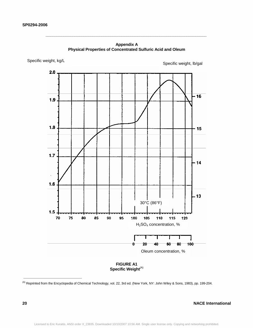
SP0294-2006
________________________________________________________________________
Appendix A Physical Properties of Concentrated Sulfuric Acid and Oleum
FIGURE A1 Specific Weight(A)
__________________________________________
(A) Reprinted from the Encyclopedia of Chemical Technology, vol. 22, 3rd ed. (New York, NY: John Wiley & Sons, 1983), pp. 199-204.
Specific weight, kg/L Specific weight, lb/gal
30°C (86°F)
H2SO4 concentration, %
Oleum concentration, %
20 NACE International
Licensed to Eric Kuraitis. ANSI order X_23835. Downloaded 10/10/2007 10:56 AM. Single user license only. Copying and networking prohibited.
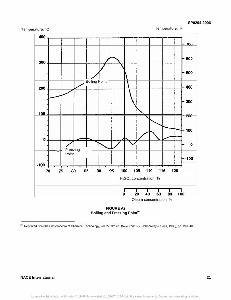
SP0294-2006
FIGURE A2 Boiling and Freezing Point(A)
__________________________________________
(A) Reprinted from the Encyclopedia of Chemical Technology, vol. 22, 3rd ed. (New York, NY: John Wiley & Sons, 1983), pp. 199-204.
Temperature, °F
Oleum concentration, %
H2SO4 concentration, %
Freezing Point
Boiling Point
Temperature, °C
NACE International 21
Licensed to Eric Kuraitis. ANSI order X_23835. Downloaded 10/10/2007 10:56 AM. Single user license only. Copying and networking prohibited.
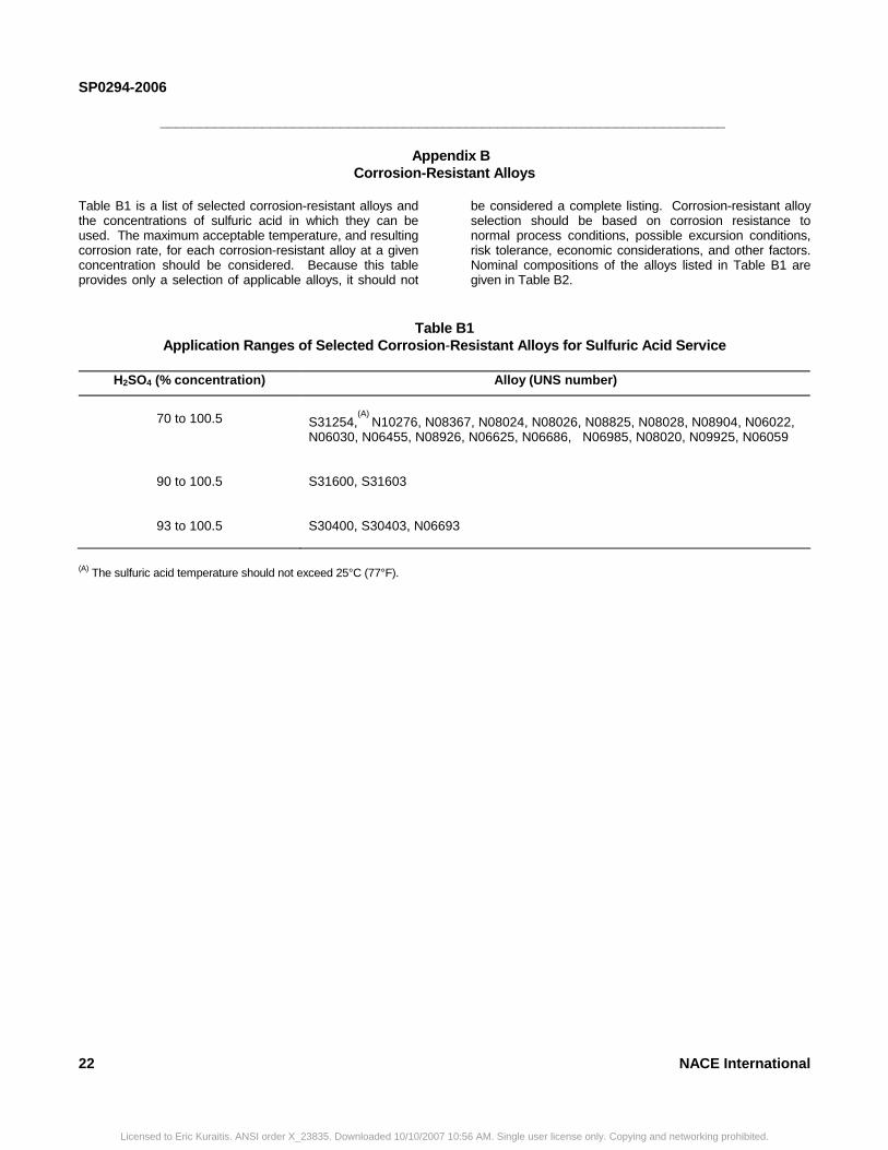
SP0294-2006
________________________________________________________________________
Appendix B Corrosion-Resistant Alloys
Table B1 is a list of selected corrosion-resistant alloys and the concentrations of sulfuric acid in which they can be used. The maximum acceptable temperature, and resulting corrosion rate, for each corrosion-resistant alloy at a given concentration should be considered. Because this table provides only a selection of applicable alloys, it should not
be considered a complete listing. Corrosion-resistant alloy selection should be based on corrosion resistance to normal process conditions, possible excursion conditions, risk tolerance, economic considerations, and other factors. Nominal compositions of the alloys listed in Table B1 are given in Table B2.
Table B1 Application Ranges of Selected Corrosion-Resistant Alloys for Sulfuric Acid Service
H2SO4 (% concentration) Alloy (UNS number)
70 to 100.5
S31254,
(A) N10276, N08367, N08024, N08026, N08825, N08028, N08904, N06022, N06030, N06455, N08926, N06625, N06686, N06985, N08020, N09925, N06059
90 to 100.5 S31600, S31603
93 to 100.5
S30400, S30403, N06693
(A) The sulfuric acid temperature should not exceed 25°C (77°F).
22 NACE International
Licensed to Eric Kuraitis. ANSI order X_23835. Downloaded 10/10/2007 10:56 AM. Single user license only. Copying and networking prohibited.
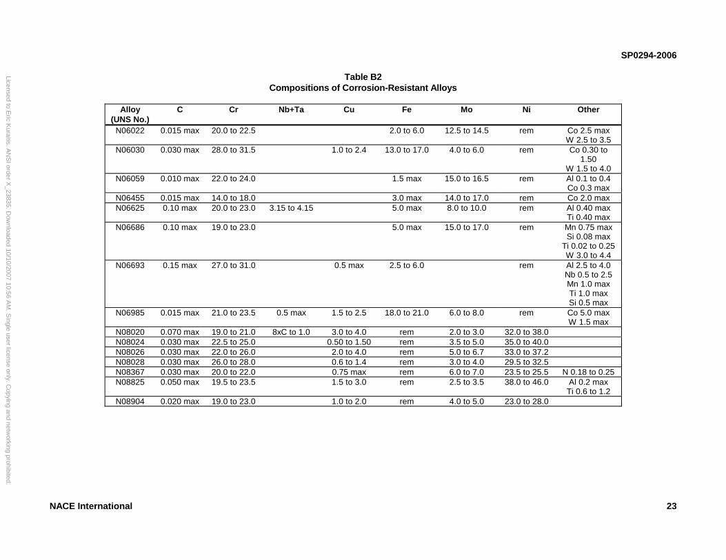
SP0294-2006
23
t Alloys
Mo Ni Other
12.5 to 14.5 rem Co 2.5 max W 2.5 to 3.5
.0 4.0 to 6.0 rem Co 0.30 to 1.50
W 1.5 to 4.0 15.0 to 16.5 rem Al 0.1 to 0.4
Co 0.3 max 14.0 to 17.0 rem Co 2.0 max 8.0 to 10.0 rem Al 0.40 max
Ti 0.40 max 15.0 to 17.0 rem Mn 0.75 max
Si 0.08 max Ti 0.02 to 0.25 W 3.0 to 4.4
rem Al 2.5 to 4.0 Nb 0.5 to 2.5 Mn 1.0 max Ti 1.0 max Si 0.5 max
.0 6.0 to 8.0 rem Co 5.0 max W 1.5 max
2.0 to 3.0 32.0 to 38.0 3.5 to 5.0 35.0 to 40.0 5.0 to 6.7 33.0 to 37.2 3.0 to 4.0 29.5 to 32.5 6.0 to 7.0 23.5 to 25.5 N 0.18 to 0.25 2.5 to 3.5 38.0 to 46.0 Al 0.2 max
Ti 0.6 to 1.2 4.0 to 5.0 23.0 to 28.0
Licensed to Eric K
uraitis. AN
SI order X
_23835. Dow
nloaded 10/10/2007 10:56 AM
. Single user license only. C
opying and networking prohibited.
NACE International
Table B2 Compositions of Corrosion-Resistan
Alloy
(UNS No.) C Cr Nb+Ta Cu Fe
N06022 0.015 max 20.0 to 22.5 2.0 to 6.0
N06030 0.030 max 28.0 to 31.5 1.0 to 2.4 13.0 to 17
N06059 0.010 max 22.0 to 24.0 1.5 max
N06455 0.015 max 14.0 to 18.0 3.0 maxN06625 0.10 max 20.0 to 23.0 3.15 to 4.15 5.0 max
N06686 0.10 max 19.0 to 23.0 5.0 max
N06693 0.15 max 27.0 to 31.0 0.5 max 2.5 to 6.0
N06985 0.015 max 21.0 to 23.5 0.5 max 1.5 to 2.5 18.0 to 21
N08020 0.070 max 19.0 to 21.0 8xC to 1.0 3.0 to 4.0 rem N08024 0.030 max 22.5 to 25.0 0.50 to 1.50 rem N08026 0.030 max 22.0 to 26.0 2.0 to 4.0 rem N08028 0.030 max 26.0 to 28.0 0.6 to 1.4 rem N08367 0.030 max 20.0 to 22.0 0.75 max rem N08825 0.050 max 19.5 to 23.5 1.5 to 3.0 rem
N08904 0.020 max 19.0 to 23.0 1.0 to 2.0 rem
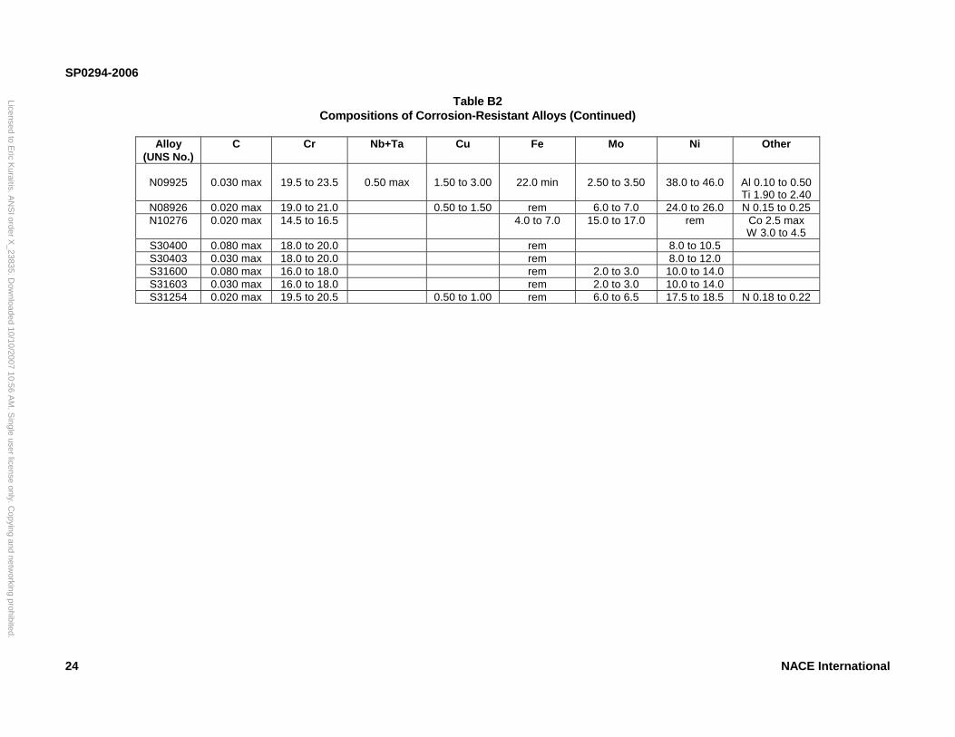
SP0294-2006
24 NACE International
Table B2 positions of Corrosion-Resistant Alloys (Continued)
Nb+Ta Cu Fe Mo Ni Other
0.50 max
1.50 to 3.00
22.0 min
2.50 to 3.50
38.0 to 46.0
Al 0.10 to 0.50 Ti 1.90 to 2.40
0.50 to 1.50 rem 6.0 to 7.0 24.0 to 26.0 N 0.15 to 0.25 4.0 to 7.0 15.0 to 17.0 rem Co 2.5 max
W 3.0 to 4.5 rem 8.0 to 10.5 rem 8.0 to 12.0 rem 2.0 to 3.0 10.0 to 14.0 rem 2.0 to 3.0 10.0 to 14.0 0.50 to 1.00 rem 6.0 to 6.5 17.5 to 18.5 N 0.18 to 0.22
Licensed to Eric K
uraitis. AN
SI order X
_23835. Dow
nloaded 10/10/2007 10:56 AM
. Single user license only. C
opying and networking prohibited.
Com
Alloy (UNS No.)
C Cr
N09925
0.030 max
19.5 to 23.5
N08926 0.020 max 19.0 to 21.0N10276 0.020 max 14.5 to 16.5
S30400 0.080 max 18.0 to 20.0S30403 0.030 max 18.0 to 20.0S31600 0.080 max 16.0 to 18.0S31603 0.030 max 16.0 to 18.0S31254 0.020 max 19.5 to 20.5
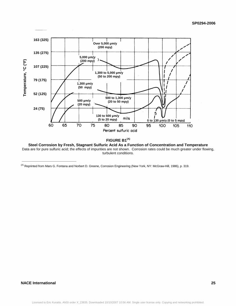
SP0294-2006
FIGURE B1(A) Steel Corrosion by Fresh, Stagnant Sulfuric Acid As a Function of Concentration and Temperature
Data are for pure sulfuric acid; the effects of impurities are not shown. Corrosion rates could be much greater under flowing, turbulent conditions.
__________________________________________
(A) Reprinted from Mars G. Fontana and Norbert D. Greene, Corrosion Engineering (New York, NY: McGraw-Hill, 1986), p. 319.
163 (325) 135 (275)
107 (225) 79 (175)
52 (125)
24 (75)
Tem
per
atu
re, °
C (
°F)
1,300 to 5,000 µm/y (50 to 200 mpy)
500 to 1,300 µm/y (20 to 50 mpy)
130 to 500 µm/y (5 to 20 mpy) 0 to 130 µm/y (0 to 5 mpy)
Over 5,000 µm/y (200 mpy)
5,000 µm/y (200 mpy)
1,300 µm/y (50 mpy)
500 µm/y (20 mpy)
NACE International 25
Licensed to Eric Kuraitis. ANSI order X_23835. Downloaded 10/10/2007 10:56 AM. Single user license only. Copying and networking prohibited.
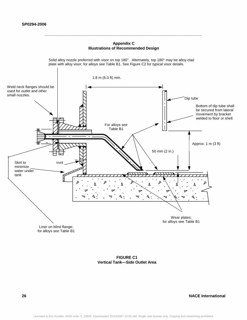
SP0294-2006
26 NACE International
________________________________________________________________________
Appendix C Illustrations of Recommended Design
Weld neck flanges should be used for outlet and other small nozzles.
Solid alloy nozzle preferred with visor on top 180°. Alternately, top 180° may be alloy-clad plate with alloy visor; for alloys see Table B1. See Figure C2 for typical visor details.
1.8 m (6.0 ft) min.
Dip tube
Bottom of dip tube shall be secured from lateral movement by bracket welded to floor or shell. For alloys see
Table B1
Approx. 1 m (3 ft)
Vent Skirt to minimize water under tank
Liner on blind flange; for alloys see Table B1
FIGURE C1 Vertical Tank—Side Outlet Area
Wear plates; for alloys see Table B1
50 mm (2 in.)
Licensed to Eric Kuraitis. ANSI order X_23835. Downloaded 10/10/2007 10:56 AM. Single user license only. Copying and networking prohibited.
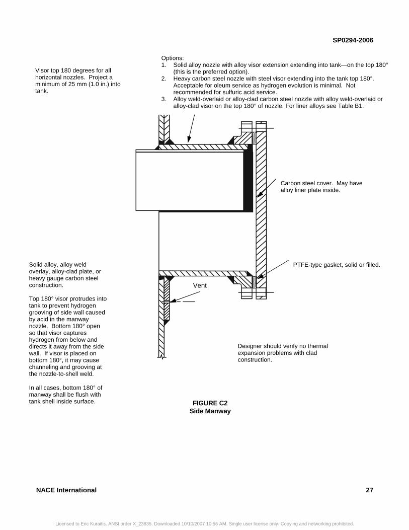
SP0294-2006
NACE International 27
Options: 1. Solid alloy nozzle with alloy visor extension extending into tank—on the top 180°
(this is the preferred option). 2. Heavy carbon steel nozzle with steel visor extending into the tank top 180°.
Acceptable for oleum service as hydrogen evolution is minimal. Not recommended for sulfuric acid service.
3. Alloy weld-overlaid or alloy-clad carbon steel nozzle with alloy weld-overlaid or alloy-clad visor on the top 180° of nozzle. For liner alloys see Table B1.
Visor top 180 degrees for all horizontal nozzles. Project a minimum of 25 mm (1.0 in.) into tank.
Solid alloy, alloy weld overlay, alloy-clad plate, or heavy gauge carbon steel construction. Top 180° visor protrudes into tank to prevent hydrogen grooving of side wall caused by acid in the manway nozzle. Bottom 180° open so that visor captures hydrogen from below and directs it away from the side wall. If visor is placed on bottom 180°, it may cause channeling and grooving at the nozzle-to-shell weld. In all cases, bottom 180° of manway shall be flush with tank shell inside surface.
Vent
Carbon steel cover. May have alloy liner plate inside.
PTFE-type gasket, solid or filled.
FIGURE C2 Side Manway
Designer should verify no thermal expansion problems with clad construction.
Licensed to Eric Kuraitis. ANSI order X_23835. Downloaded 10/10/2007 10:56 AM. Single user license only. Copying and networking prohibited.
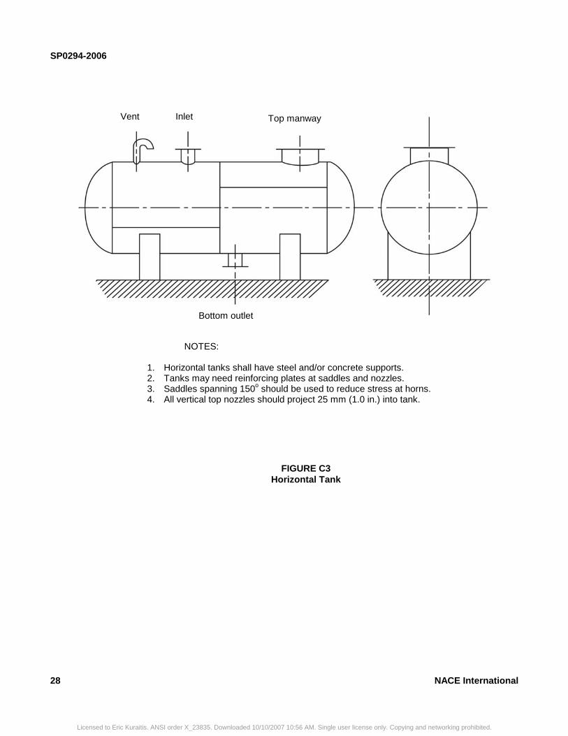
SP0294-2006
28 NACE International
FIGURE C3 Horizontal Tank
Top manway Inlet Vent
Bottom outlet
NOTES:
1. Horizontal tanks shall have steel and/or concrete supports. 2. Tanks may need reinforcing plates at saddles and nozzles. 3. Saddles spanning 150o should be used to reduce stress at horns. 4. All vertical top nozzles should project 25 mm (1.0 in.) into tank.
Licensed to Eric Kuraitis. ANSI order X_23835. Downloaded 10/10/2007 10:56 AM. Single user license only. Copying and networking prohibited.
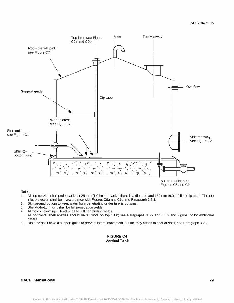
SP0294-2006
NACE International 29
Notes: 1. All top nozzles shall project at least 25 mm (1.0 in) into tank if there is a dip tube and 150 mm (6.0 in.) if no dip tube. The top
inlet projection shall be in accordance with Figures C6a and C6b and Paragraph 3.2.1. 2. Skirt around bottom to keep water from penetrating under tank is optional. 3. Shell-to-bottom joint shall be full penetration welds. 4. All welds below liquid level shall be full penetration welds. 5. All horizontal shell nozzles should have visors on top 180°; see Paragraphs 3.5.2 and 3.5.3 and Figure C2 for additional
details. 6. Dip tube shall have a support guide to prevent lateral movement. Guide may attach to floor or shell, see Paragraph 3.2.2.
FIGURE C4 Vertical Tank
Vent Top inlet; see Figure C6a and C6b
Roof-to-shell joint; see Figure C7
Overflow
Side manway See Figure C2
Dip tube
Support guide
Side outlet; see Figure C1
Wear plates; see Figure C1
Shell-to-bottom joint
Bottom outlet; see Figures C8 and C9
Top Manway
Licensed to Eric Kuraitis. ANSI order X_23835. Downloaded 10/10/2007 10:56 AM. Single user license only. Copying and networking prohibited.
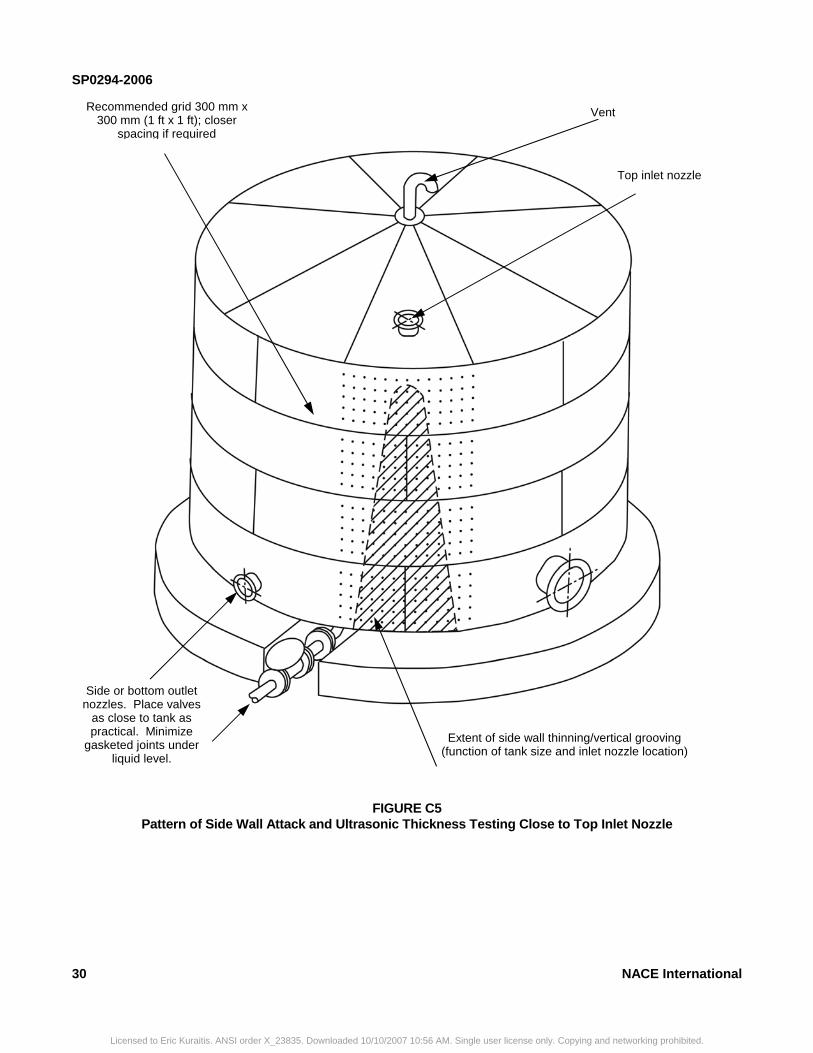
SP0294-2006
30 NACE International
FIGURE C5 Pattern of Side Wall Attack and Ultrasonic Thickness Testing Close to Top Inlet Nozzle
Recommended grid 300 mm x 300 mm (1 ft x 1 ft); closer
spacing if required
Vent
Top inlet nozzle
Side or bottom outlet nozzles. Place valves
as close to tank as practical. Minimize
gasketed joints under liquid level.
Extent of side wall thinning/vertical grooving (function of tank size and inlet nozzle location)
Licensed to Eric Kuraitis. ANSI order X_23835. Downloaded 10/10/2007 10:56 AM. Single user license only. Copying and networking prohibited.
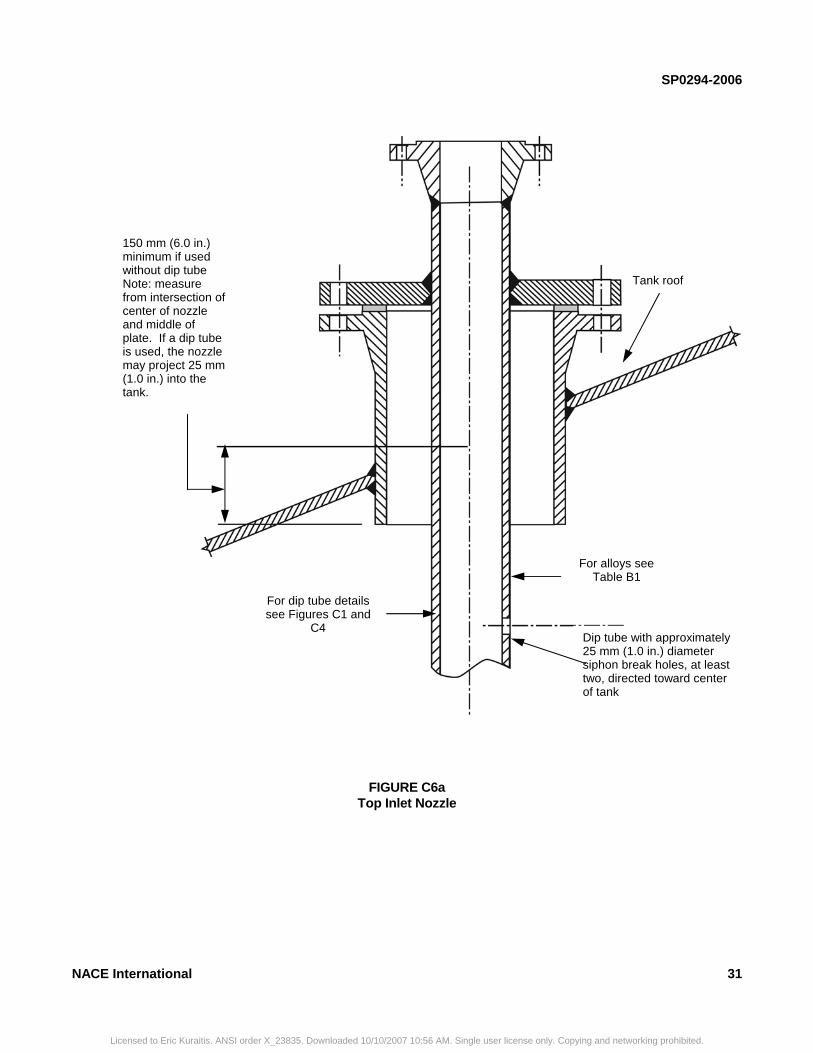
SP0294-2006
NACE International 31
FIGURE C6a Top Inlet Nozzle
150 mm (6.0 in.) minimum if used without dip tube Note: measure from intersection of center of nozzle and middle of plate. If a dip tube is used, the nozzle may project 25 mm (1.0 in.) into the tank.
Tank roof
For alloys see Table B1
Dip tube with approximately 25 mm (1.0 in.) diameter siphon break holes, at least two, directed toward center of tank
For dip tube details see Figures C1 and
C4
Licensed to Eric Kuraitis. ANSI order X_23835. Downloaded 10/10/2007 10:56 AM. Single user license only. Copying and networking prohibited.
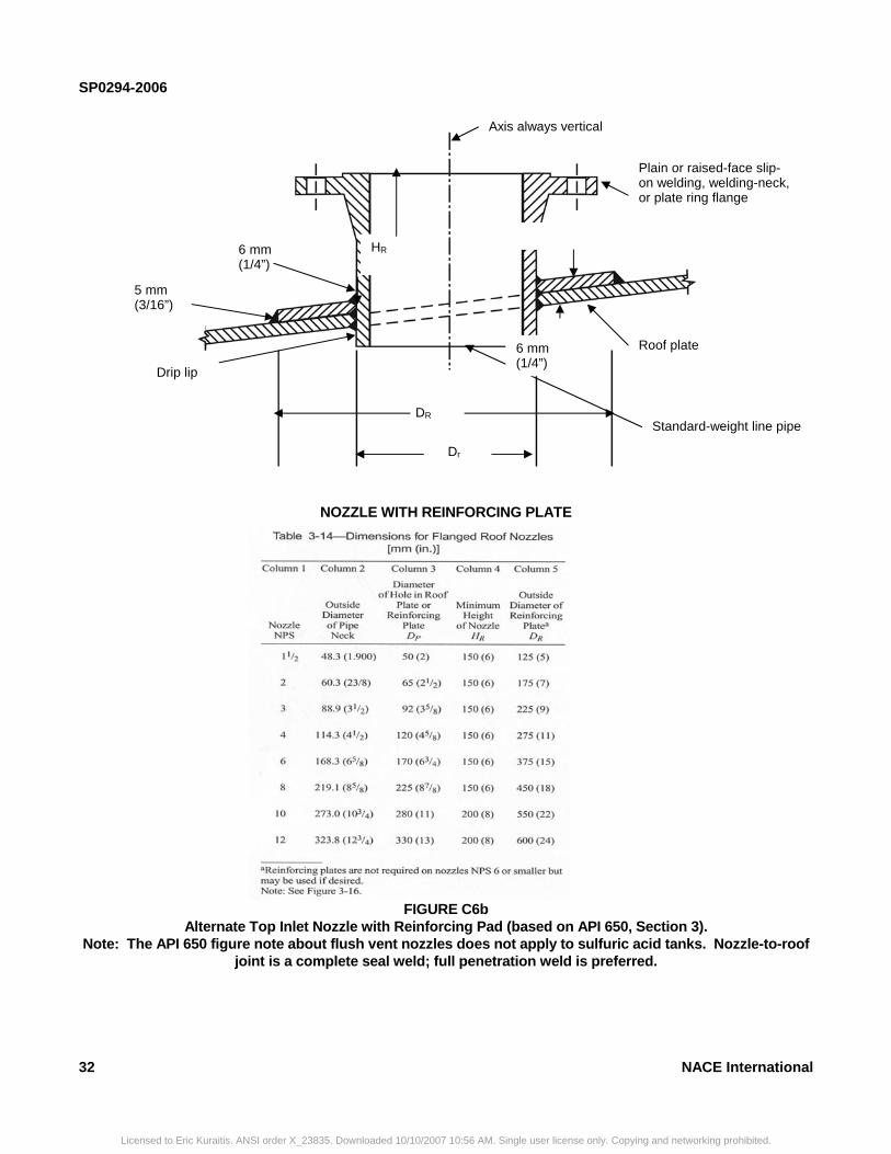
SP0294-2006
32 NACE International
NOZZLE WITH REINFORCING PLATE
FIGURE C6b Alternate Top Inlet Nozzle with Reinforcing Pad (based on API 650, Section 3).
Note: The API 650 figure note about flush vent nozzles does not apply to sulfuric acid tanks. Nozzle-to-roof joint is a complete seal weld; full penetration weld is preferred.
Axis always vertical
Plain or raised-face slip-on welding, welding-neck, or plate ring flange
5 mm (3/16”)
Roof plate
Drip lip
6 mm (1/4”)
Standard-weight line pipe
HR
6 mm (1/4”)
DR
Dr
Licensed to Eric Kuraitis. ANSI order X_23835. Downloaded 10/10/2007 10:56 AM. Single user license only. Copying and networking prohibited.
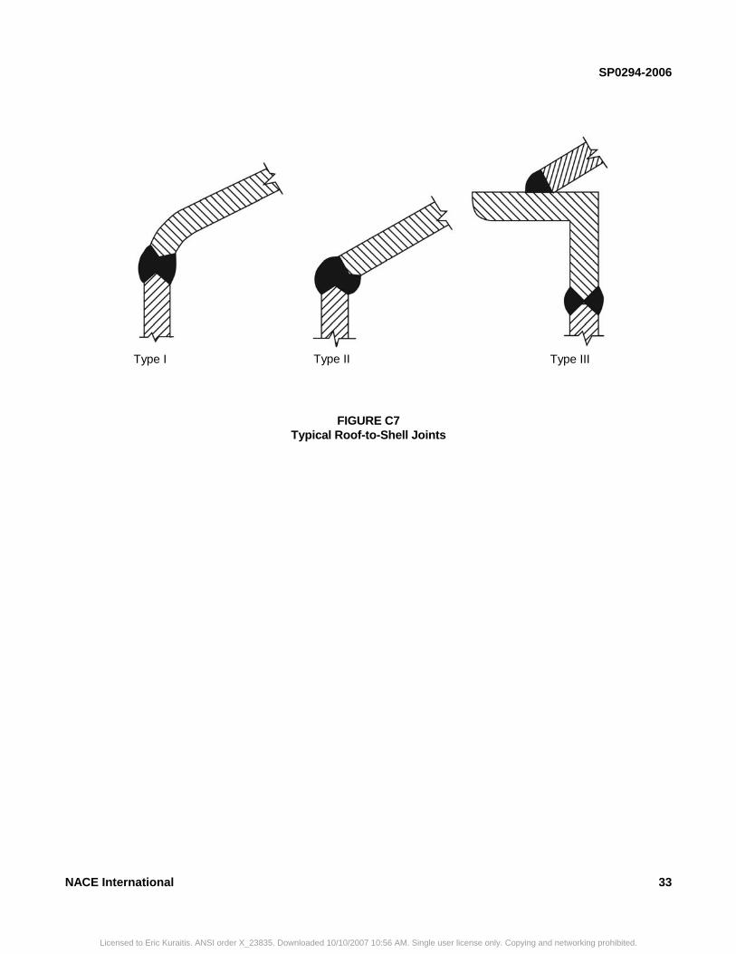
SP0294-2006
NACE International 33
FIGURE C7 Typical Roof-to-Shell Joints
Type I Type II Type III
Licensed to Eric Kuraitis. ANSI order X_23835. Downloaded 10/10/2007 10:56 AM. Single user license only. Copying and networking prohibited.

SP0294-2006
34 NACE International
FIGURE C8 Bottom Outlet Nozzle—Alloy Construction
480 mm (19 in.) minimum
Schedule 80S alloy pipe; UNS N08020, N08024, N08026 preferred.
6.4 mm (0.25 in.) NPT telltale hole, filled with silicon grease after tank painting.
Solid alloy construction preferred, clad construction optional; for material alloys see Table B1.
Licensed to Eric Kuraitis. ANSI order X_23835. Downloaded 10/10/2007 10:56 AM. Single user license only. Copying and networking prohibited.
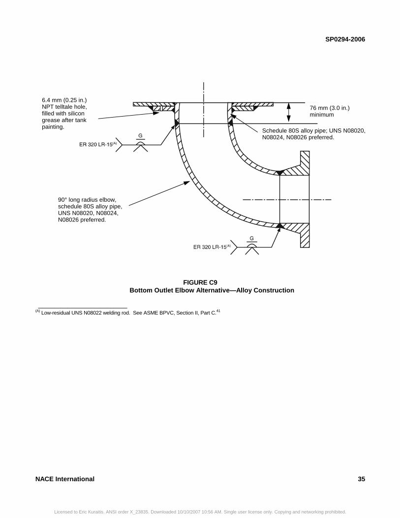
SP0294-2006
FIGURE C9 Bottom Outlet Elbow Alternative—Alloy Construction
___________________________
(A) Low-residual UNS N08022 welding rod. See ASME BPVC, Section II, Part C.41
6.4 mm (0.25 in.) NPT telltale hole, filled with silicon grease after tank painting.
90° long radius elbow, schedule 80S alloy pipe, UNS N08020, N08024, N08026 preferred.
Schedule 80S alloy pipe; UNS N08020, N08024, N08026 preferred.
76 mm (3.0 in.) minimum
NACE International 35
Licensed to Eric Kuraitis. ANSI order X_23835. Downloaded 10/10/2007 10:56 AM. Single user license only. Copying and networking prohibited.
SP0294-2006
36
________________________________________________________________________
Appendix D Radiographic Acceptance Standard for Welded Equipment in Corrosive Service
________________________________________________________________________
Section D1: Scope
D1.1 This appendix provides recommended acceptance levels for radiographic inspection of butt welds in corrosive service for tanks constructed of carbon steel or corrosion-resistant alloys. The following guidelines on allowable
levels and sizes of defects are more stringent than those allowed in applicable codes and standards. Most applicable codes and standards are directed at noncorrosive environments only.
________________________________________________________________________
Section D2: Terminology
D2.1 Rounded indications—Indications with a maximum length of three times the width. These may be circular, elliptical, conical, or irregular in shape and may have tails. When evaluating the size of an indication, the tail shall be included. The indications may be from any source in the weld such as porosity, slag, or tungsten. D2.2 Elongated indications—Indications with a length of more than three times the width.
______________________________________
Licensed to Eric Kuraitis. ANSI order X_23835. Downloaded 10/10/2007 1
D2.3 Aligned indications—A sequence of four or more rounded indications shall be considered to be aligned when they touch a line drawn through the center of the two outer rounded indications. D2.4 Relevant indications—Only those indications on the radiograph with a maximum dimension greater than 0.3 mm (0.01 in.) shall be considered relevant.
__________________________________
Section D3: Acceptance Criteria
D3.1 Sections of welds that are shown by radiography to have any of the following types of imperfections shall be judged unacceptable:
D3.1.1 Any type of crack or zone of incomplete fusion or penetration, regardless of its length. D3.1.2 Any elongated slag inclusion, regardless of its length. Slag inclusions in the form of rounded indications shall be acceptable only within the limitations of Paragraph D3.1.3.
0:56 A
D3.1.3 Rounded indications greater than those shown in Table D1. The minimum distance between any two rounded indications shall be 6.4 mm (0.25 in.) or 1/3 thickness, whichever is greater. Examples of assorted indications are shown in Figures D1 and D2. D3.1.4 Aligned, rounded indications. NOTE: Image density of the indications may vary and is not a criterion for acceptance or rejection.
NACE International
M. Single user license only. Copying and networking prohibited.
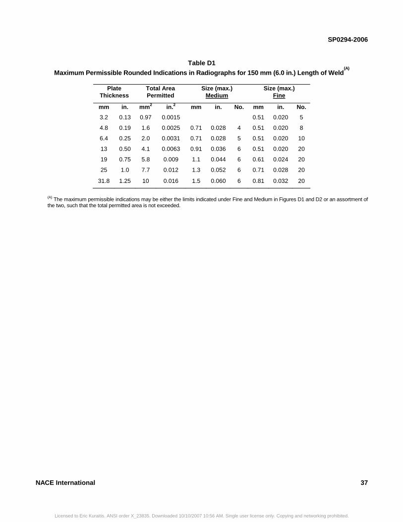
SP0294-2006
Table D1
Maximum Permissible Rounded Indications in Radiographs for 150 mm (6.0 in.) Length of Weld(A)
Plate Thickness
Total Area Permitted
Size (max.) Medium
Size (max.) Fine
mm in. mm2 in.2 mm in. No. mm in. No.
3.2 0.13 0.97 0.0015 0.51 0.020 5
4.8 0.19 1.6 0.0025 0.71 0.028 4 0.51 0.020 8
6.4 0.25 2.0 0.0031 0.71 0.028 5 0.51 0.020 10
13 0.50 4.1 0.0063 0.91 0.036 6 0.51 0.020 20
19 0.75 5.8 0.009 1.1 0.044 6 0.61 0.024 20
25 1.0 7.7 0.012 1.3 0.052 6 0.71 0.028 20
31.8 1.25 10 0.016 1.5 0.060 6 0.81 0.032 20
(A) The maximum permissible indications may be either the limits indicated under Fine and Medium in Figures D1 and D2 or an assortment of the two, such that the total permitted area is not exceeded.
NACE International 37
Licensed to Eric Kuraitis. ANSI order X_23835. Downloaded 10/10/2007 10:56 AM. Single user license only. Copying and networking prohibited.
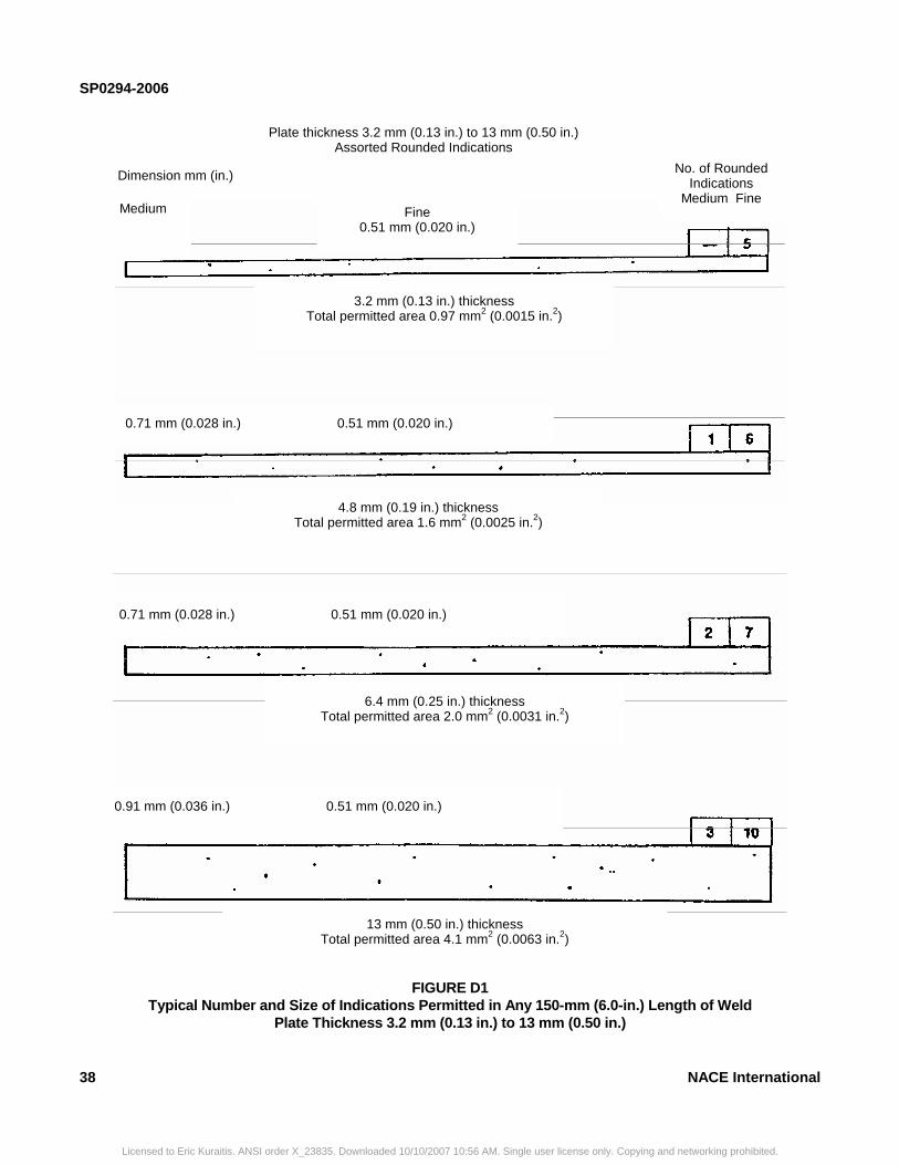
SP0294-2006
FIGURE D1 Typical Number and Size of Indications Permitted in Any 150-mm (6.0-in.) Length of Weld
Plate Thickness 3.2 mm (0.13 in.) to 13 mm (0.50 in.)
Plate thickness 3.2 mm (0.13 in.) to 13 mm (0.50 in.) Assorted Rounded Indications
Dimension mm (in.)
Medium —
Fine 0.51 mm (0.020 in.)
No. of Rounded Indications
Medium Fine
4.8 mm (0.19 in.) thickness Total permitted area 1.6 mm2 (0.0025 in.2)
0.71 mm (0.028 in.) 0.51 mm (0.020 in.)
0.71 mm (0.028 in.) 0.51 mm (0.020 in.)
6.4 mm (0.25 in.) thickness Total permitted area 2.0 mm2 (0.0031 in.2)
0.91 mm (0.036 in.) 0.51 mm (0.020 in.)
13 mm (0.50 in.) thickness Total permitted area 4.1 mm2 (0.0063 in.2)
3.2 mm (0.13 in.) thickness Total permitted area 0.97 mm2 (0.0015 in.2)
Medium —
Medium —
Medium
38 NACE International
Licensed to Eric Kuraitis. ANSI order X_23835. Downloaded 10/10/2007 10:56 AM. Single user license only. Copying and networking prohibited.
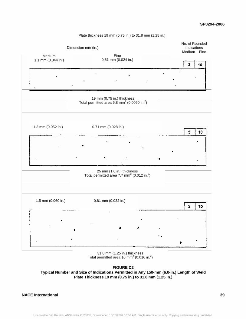
SP0294-2006
FIGURE D2 Typical Number and Size of Indications Permitted in Any 150-mm (6.0-in.) Length of Weld
Plate Thickness 19 mm (0.75 in.) to 31.8 mm (1.25 in.)
1.3 mm (0.052 in.) 0.71 mm (0.028 in.)
25 mm (1.0 in.) thickness Total permitted area 7.7 mm2 (0.012 in.2)
1.5 mm (0.060 in.) 0.81 mm (0.032 in.)
31.8 mm (1.25 in.) thickness Total permitted area 10 mm2 (0.016 in.2)
Dimension mm (in.)
Plate thickness 19 mm (0.75 in.) to 31.8 mm (1.25 in.)
19 mm (0.75 in.) thickness Total permitted area 5.8 mm2 (0.0090 in.2)
Medium 1.1 mm (0.044 in.)
Fine 0.61 mm (0.024 in.)
No. of Rounded Indications
Medium Fine
NACE International 39
Licensed to Eric Kuraitis. ANSI order X_23835. Downloaded 10/10/2007 10:56 AM. Single user license only. Copying and networking prohibited.