n7ve battery status indicator (bsi) - qrp kits - pacific ... 0.pdfn7ve battery status indicator v1...
TRANSCRIPT
N7VE Battery Status Indicator v1 .0 Page 1 of 24
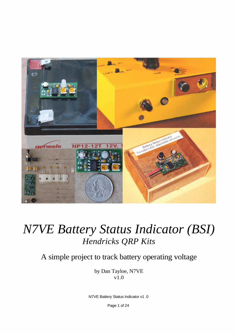
N7VE Battery Status Indicator (BSI) Hendricks QRP Kits
A simple project to track battery operating voltage
by Dan Tayloe, N7VE v1.0

Table of Contents
Acknowledgements ..........................................................................................................................................3 Kit Parts .................................................................................................................................................................... 4 Specifications...........................................................................................................................................................5 Building the Battery Status Indicator (B SI).......................................................................................................... 6
Common parts assembly............................................................................................................................................7 Final part placement for the flat mounted configuration ........................................................................ 10 Final assembly of the panel mount configuration ................................................................................... 12
Initial DC tests................................................................................................................................................ 15 Calibration and Usage of the BSI.........................................................................................................................16
Two cases with the BSI on all the time ...........................................................................................................17 The large battery case...................................................................................................................................17 Low voltage only configuration ..................................................................................................................17
Mounting the panel mount configuration to a PFR-3........................................................................................17 Schematic ...............................................................................................................................................................19 Appendix A. Battery Specifications....................................................................................................................20
1 2v Gell Cell....................................................................................................................................................................20 NiMH batteries...........................................................................................................................................21 NiCad batteries ..................................................................................................................................................22 Lithium-Ion Rechargeables...............................................................................................................................23 Alkaline Non-rechargables................................................................................................................................24
List of Figures
Figure 1. Kit bag of parts right out of the box.................................................................................................4 Figure 2. Contents of the bag identified...........................................................................................................4 Figure 3. Flat Mount Configuration...................................................................................................................... 6 Figure 4. Panel Mount Configuration ...................................................................................................................7 Figure 5. Mounting location of C1, C2, C3, and C4...........................................................................................7 Figure 6. Lead forming for C1 – C4. .................................................................................................................... 8 Figure 7. Capacitors need to be mounted close to the board with short leads...............................................8 Figure 8. Lead forming for the four resistors. Bend lead tight to the top.....................................................9 Figure 9. Mounting locations of R3, R4, R5, and R6. Note tight bends, with resistor mounted close to
the board..........................................................................................................................................................9 Figure 10. IC1, D1, and D2 mounted. Note the band directions on D1 and D2! ......................................10 Figure 11. Example of the BSI mounted to the top of a gell cell. ......................................................... 10 Figure 12. LED leads must be raised just off the surface of the PC board............................................ 11 Figure 13. Location of the LED, two trim pots, and push button switch............................................... 11 Figure 14. BSI panel mount configuration installed in a PFR-3..................................................................12 Figure 15. The trim pots are mounted to the bottom side of the board........................................................12 Figure 16. Panel mount push button before and after rework of the switch leads ................................ 13 Figure 17. Mechanical drawing of the switch and LED installation on to the PC board...................... 13 Figure 18. LED Notch location shown...............................................................................................................14 Figure 19. Power connections shown. Red and green LED threshold trim pots identified .................. 15
N7VE Battery Status Indicator v1 .0

N7VE Battery Status Indicator v1 .0 Page 3 of 24
Page 2 of 24
Figure 20. Example calibration thresholds for a 12v gell cell battery ................................................... 16 Figure 21. 100% active, minimum current consumption arrangement .......................................................17 Figure 22. Mechanical drawing for hole position and drill sizes for attaching to a PFR-3........................18 Figure 23. Inside look of a BSI installed in a PFR-3. Back side location of trim pots allow adjustment
when installed......................................................................................................................................... 19 Figure 24. Voltage discharge rating for a 12v, 9 AH gell cell battery (Power Sonic PS-1282S)..............20 Figure 25. Voltage discharge curve for a 1 .2v AA NiMH battery. Curve shown is a 2500 mAH
Energizer NH15-2500 .................................................................................................................................21 Figure 26. Voltage discharge curve for a 1.2v AA NiCad battery. Curve is a 1000 mAH GP Batteries
GP100AAKC .........................................................................................................................................22 Figure 27. Voltage discharge curve for a 3.7v Lithium-Ion battery. Curve is a 1800 mAH Ultralife
UBBP01 .........................................................................................................................................................23 Figure 28. Voltage discharge curve for a 1.5v AA alkaline battery. Curve is a Energizer EN91............24
Acknowledgements
All mechanical drawings and all pictures of the BSI mounted in a PFR-3 were produced by Ken LoCasale, WA4MNT. Ken was a great help in doing the mechanical engineering that set up the general location of specific parts on the PC board such as the switch, the LED, the trim pots and the over all board dimensions so that the PC board would fit inside the PFR-3 without interference to other parts in the transceiver.
N7VE Battery Status Indicator v1 .0 Page 5 of 24
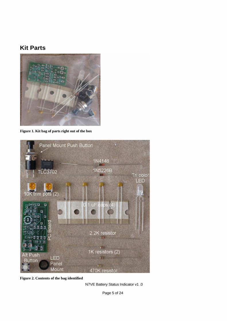
Kit Parts
Figure 2. Contents of the bag identified
Figure 1. Kit bag of parts right out of the box
N7VE Battery Status Indicator v1 .0 Page 6 of 24
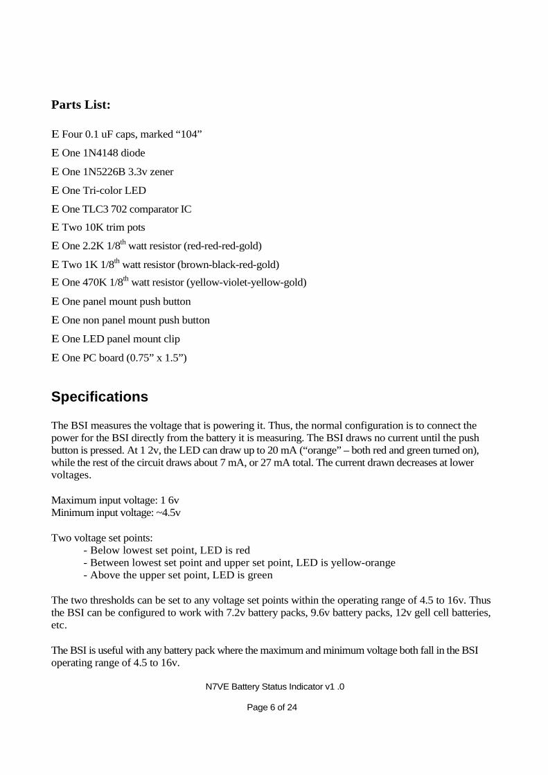
Parts List:
E Four 0.1 uF caps, marked “104”
E One 1N4148 diode
E One 1N5226B 3.3v zener
E One Tri-color LED
E One TLC3 702 comparator IC
E Two 10K trim pots
E One 2.2K 1/8th watt resistor (red-red-red-gold)
E Two 1K 1/8th watt resistor (brown-black-red-gold)
E One 470K 1/8th watt resistor (yellow-violet-yellow-gold)
E One panel mount push button
E One non panel mount push button
E One LED panel mount clip
E One PC board (0.75” x 1.5”)
Specifications
The BSI measures the voltage that is powering it. Thus, the normal configuration is to connect the power for the BSI directly from the battery it is measuring. The BSI draws no current until the push button is pressed. At 1 2v, the LED can draw up to 20 mA (“orange” – both red and green turned on), while the rest of the circuit draws about 7 mA, or 27 mA total. The current drawn decreases at lower voltages.
Maximum input voltage: 1 6v Minimum input voltage: ~4.5v
Two voltage set points: - Below lowest set point, LED is red - Between lowest set point and upper set point, LED is yellow-orange - Above the upper set point, LED is green
The two thresholds can be set to any voltage set points within the operating range of 4.5 to 16v. Thus the BSI can be configured to work with 7.2v battery packs, 9.6v battery packs, 12v gell cell batteries, etc.
The BSI is useful with any battery pack where the maximum and minimum voltage both fall in the BSI operating range of 4.5 to 16v.
N7VE Battery Status Indicator v1 .0 Page 7 of 24
Building the Battery Status Indicator (BSI)
Note: There are two different kit configurations! - One for a panel mount such as inside a rig - One for a flat mount such as on top of a battery pack
Note: Order is important: LED, Switch, and Trim Pot mounting depends on the kit configuration (flat or panel mount)!
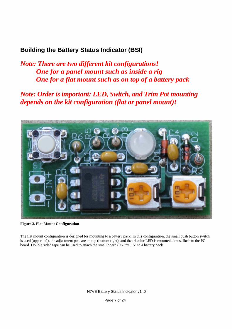
Figure 3. Flat Mount Configuration
The flat mount configuration is designed for mounting to a battery pack. In this configuration, the small push button switch is used (upper left), the adjustment pots are on top (bottom right), and the tri color LED is mounted almost flush to the PC board. Double sided tape can be used to attach the small board (0.75”x 1.5” to a battery pack.
N7VE Battery Status Indicator v1 .0 Page 8 of 24
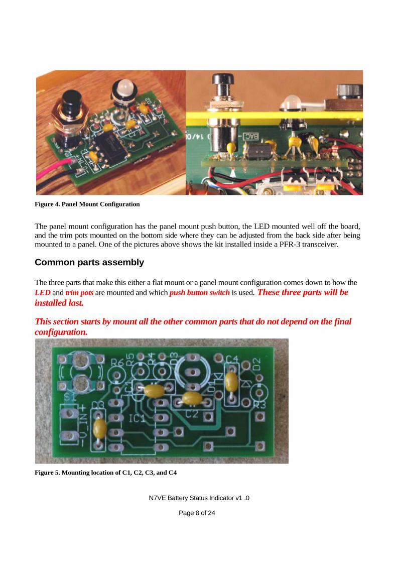
Figure 4. Panel Mount Configuration
The panel mount configuration has the panel mount push button, the LED mounted well off the board, and the trim pots mounted on the bottom side where they can be adjusted from the back side after being mounted to a panel. One of the pictures above shows the kit installed inside a PFR-3 transceiver.
Common parts assembly
The three parts that make this either a flat mount or a panel mount configuration comes down to how the LED and trim pots are mounted and which push button switch is used. These three parts will be installed last.
This section starts by mount all the other common parts that do not depend on the final configuration.
Figure 5. Mounting location of C1, C2, C3, and C4
N7VE Battery Status Indicator v1 .0 Page 9 of 24
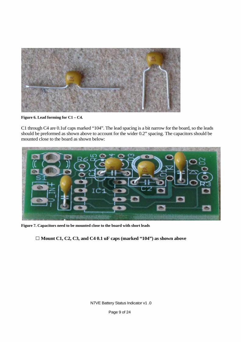
Figure 6. Lead forming for C1 – C4.
C1 through C4 are 0.1uf caps marked “104”. The lead spacing is a bit narrow for the board, so the leads should be preformed as shown above to account for the wider 0.2” spacing. The capacitors should be mounted close to the board as shown below:
Figure 7. Capacitors need to be mounted close to the board with short leads
□ Mount C1, C2, C3, and C4 0.1 uF caps (marked “104”) as shown above
N7VE Battery Status Indicator v1 .0 Page 10 of 24
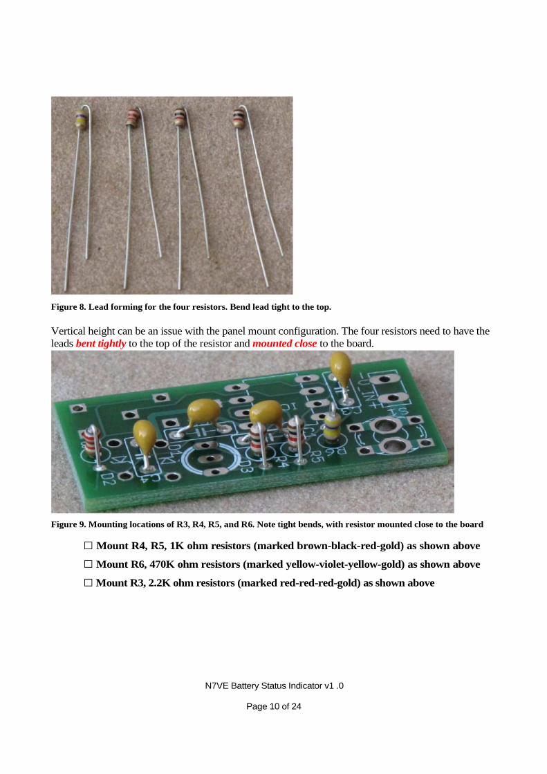
Figure 8. Lead forming for the four resistors. Bend lead tight to the top.
Vertical height can be an issue with the panel mount configuration. The four resistors need to have the leads bent tightly to the top of the resistor and mounted close to the board.
Figure 9. Mounting locations of R3, R4, R5, and R6. Note tight bends, with resistor mounted close to the board
□ Mount R4, R5, 1K ohm resistors (marked brown-black-red-gold) as shown above
□ Mount R6, 470K ohm resistors (marked yellow-violet-yellow-gold) as shown above
□ Mount R3, 2.2K ohm resistors (marked red-red-red-gold) as shown above
N7VE Battery Status Indicator v1 .0 Page 7 of 24
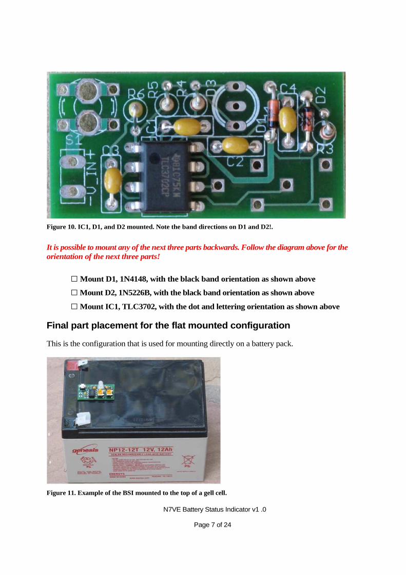
Figure 10. IC1, D1, and D2 mounted. Note the band directions on D1 and D2!.
It is possible to mount any of the next three parts backwards. Follow the diagram above for the orientation of the next three parts!
□ Mount D1, 1N4148, with the black band orientation as shown above
□ Mount D2, 1N5226B, with the black band orientation as shown above
□ Mount IC1, TLC3702, with the dot and lettering orientation as shown above
Final part placement for the flat mounted configuration
This is the configuration that is used for mounting directly on a battery pack.
Figure 11. Example of the BSI mounted to the top of a gell cell.

N7VE Battery Status Indicator v1 .0 Page 8 of 24
Figure 13. Location of the LED, two trim pots, and push button switch
□ Mount D3, the tri-color LED with the notch orientation as shown above, lifted a bit off the board as shown above.
□ Mount S1, using the low profile push button switch as shown above
□ Mount R1 and R2, the two 10K pots as shown above on the top side of the board
The build of the flat mounted configuration is now complete. Skip over to the alignment section. The tall push button switch and the LED panel mount hardware will not be needed.
Figure 12. LED leads must be raised just off the surface of the PC board.
N7VE Battery Status Indicator v1 .0 Page 9 of 24
Final assembly of the panel mount configuration
The panel mount version is designed for installation inside a rig. Specific instructions are included here for installing this kit into a PFR-3, but this kit can readily be used for other rigs or battery powered projects.
Figure 14. BSI panel mount configuration installed in a PFR-3
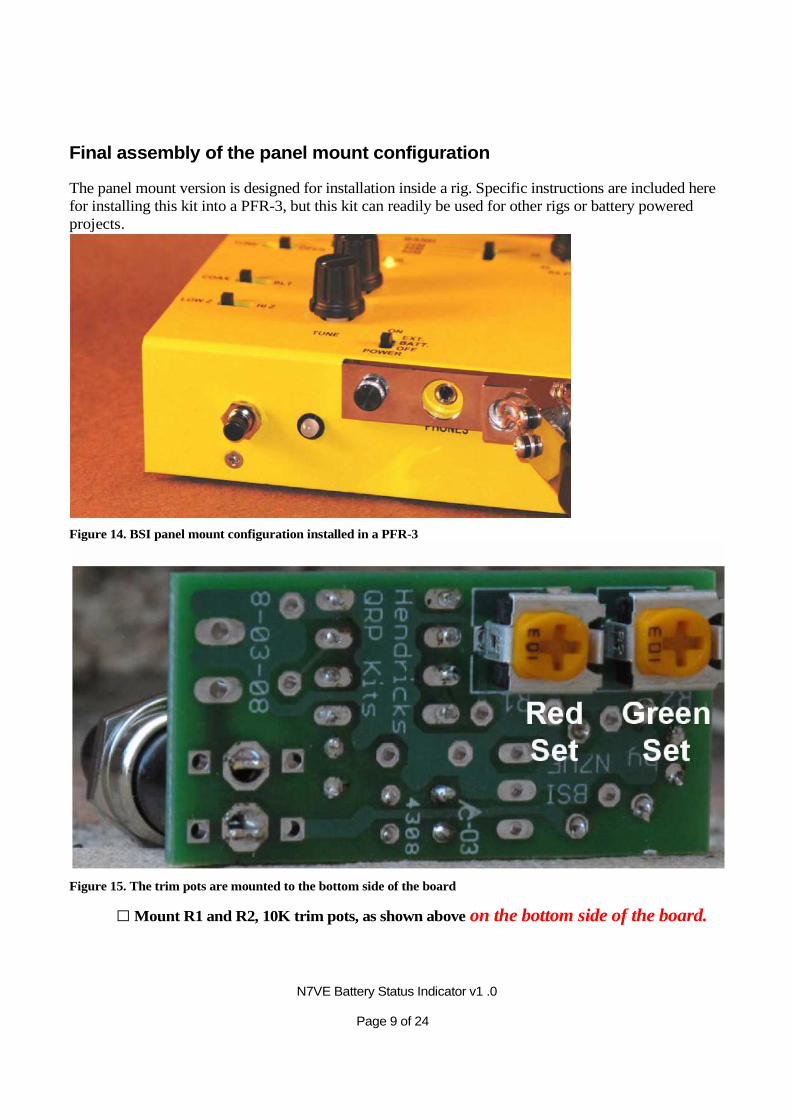
Figure 15. The trim pots are mounted to the bottom side of the board
□ Mount R1 and R2, 10K trim pots, as shown above on the bottom side of the board.
N7VE Battery Status Indicator v1 .0 Page 10 of 24
The switch that is used in this version is the taller, panel mount push button switch. Since the BSI was designed, the specifications of the push button have changed, and the leads of the current style push button switch are too large for the holes on the PCB. Thus, the leads need to be slimmed down a bit to fit the holes of the board.
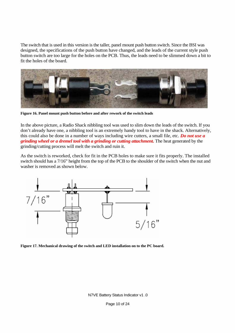
Figure 16. Panel mount push button before and after rework of the switch leads
In the above picture, a Radio Shack nibbling tool was used to slim down the leads of the switch. If you don’t already have one, a nibbling tool is an extremely handy tool to have in the shack. Alternatively, this could also be done in a number of ways including wire cutters, a small file, etc. Do not use a grinding wheel or a dremel tool with a grinding or cutting attachment. The heat generated by the grinding/cutting process will melt the switch and ruin it.
As the switch is reworked, check for fit in the PCB holes to make sure it fits properly. The installed switch should has a 7/16” height from the top of the PCB to the shoulder of the switch when the nut and washer is removed as shown below.
Figure 17. Mechanical drawing of the switch and LED installation on to the PC board.
N7VE Battery Status Indicator v1 .0 Page 11 of 24
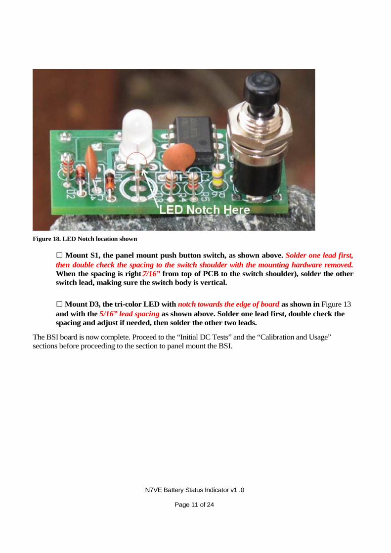
Figure 18. LED Notch location shown
□ Mount S1, the panel mount push button switch, as shown above. Solder one lead first, then double check the spacing to the switch shoulder with the mounting hardware removed. When the spacing is right (7/16” from top of PCB to the switch shoulder), solder the other switch lead, making sure the switch body is vertical.
□ Mount D3, the tri-color LED with notch towards the edge of board, as shown in Figure 13 and with the 5/16” lead spacing as shown above. Solder one lead first, double check the spacing and adjust if needed, then solder the other two leads.
The BSI board is now complete. Proceed to the “Initial DC Tests” and the “Calibration and Usage” sections before proceeding to the section to panel mount the BSI.
N7VE Battery Status Indicator v1 .0 Page 12 of 24
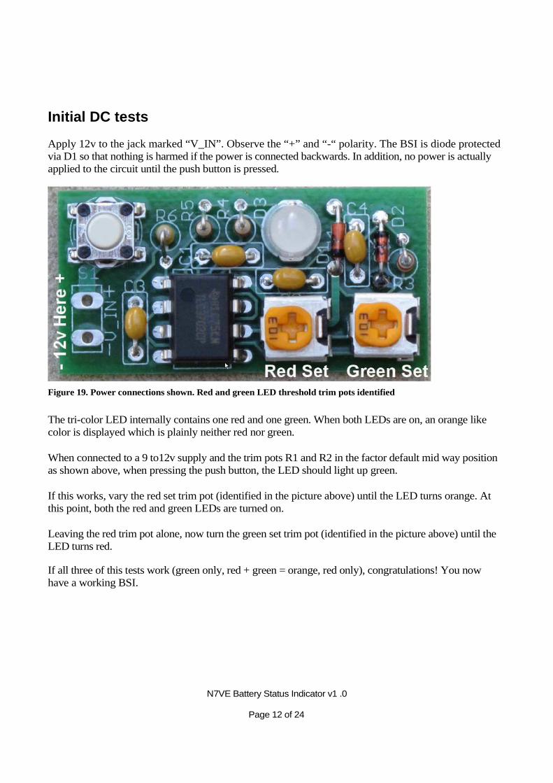
Initial DC tests
Apply 12v to the jack marked “V_IN”. Observe the “+” and “-“ polarity. The BSI is diode protected via D1 so that nothing is harmed if the power is connected backwards. In addition, no power is actually applied to the circuit until the push button is pressed.
Figure 19. Power connections shown. Red and green LED threshold trim pots identified
The tri-color LED internally contains one red and one green. When both LEDs are on, an orange like color is displayed which is plainly neither red nor green.
When connected to a 9 to12v supply and the trim pots R1 and R2 in the factor default mid way position as shown above, when pressing the push button, the LED should light up green.
If this works, vary the red set trim pot (identified in the picture above) until the LED turns orange. At this point, both the red and green LEDs are turned on.
Leaving the red trim pot alone, now turn the green set trim pot (identified in the picture above) until the LED turns red.
If all three of this tests work (green only, red + green = orange, red only), congratulations! You now have a working BSI.

N7VE Battery Status Indicator v1 .0 Page 13 of 24
Calibration and Usage of the BSI
The simplest way of calibrating the BSR is using a variable voltage power supply. Caution! Do not let the input voltage exceed 16v!
Figure 20. Example calibration thresholds for a 12v gell cell battery
The above figure shows the calibration points for a 12v gell cell battery. The color voltage thresholds will change for other battery types, but the basic concept will stay the same. The green LED will turn on for any voltage greater than its trigger point. The red LED will turn on for any voltage less than its trigger point. These trigger points are deliberately set up to overlap so that three different voltage regions can be indicated.
If a variable voltage supply is used, and the BSI is being set as above for a 12v gell cell battery, set the variable supply to 11v and adjust the red set trim pot so that the red just turns on (producing either red or orange) just below 11v. Next set the supply voltage to 10v and adjust the green set pot so that it just turns off (changing color from orange to red) just below 1 0v.
In the above example of a 12v gell cell, the voltage range of the orange color is a bit subjective. The goal is to set this range so that the operator will have sufficient warning that the battery is getting low given how often the battery might get checked.
A real life curve for a 12v, 9AH gell cell battery shows end of service at ~ 10.5v with an upper orange threshold of 11.3v rather than the simple 10v and 11v thresholds used in the above simple illustration. See appendix A for more details.
If you do not have a variable voltage power supply, then you may have to use the slower method of attaching the BSR to a battery and gradually discharging the battery using something like a rig or a resistive load. As the battery discharges, and the battery voltage passes a desired set point, the set points on the BSR can be set up using the red set and green set trim pots as listed above, thus calibrating the BSR with a slower process.
Appendix A gives battery discharge curves for a number of different battery chemistries and appropriate voltage thresholds are suggested.
N7VE Battery Status Indicator v1 .0 Page 14 of 24
Two cases with the BSI on all the time
The large battery case
In the above cases, the BSI is checked occasionally by manually pressing the push button. This is the normal operation since the LED current drawn can be a significant drain on smaller QRP type batteries (up to 25 mA at 12v with both red and green LEDs on). However, if the BSI is connected to a very large battery such as one or more car batteries in parallel, this level of current drain might be insignificant. In such a case, the switch could be bypassed with a small wire short under the board, so that the status could be tracked continuously.
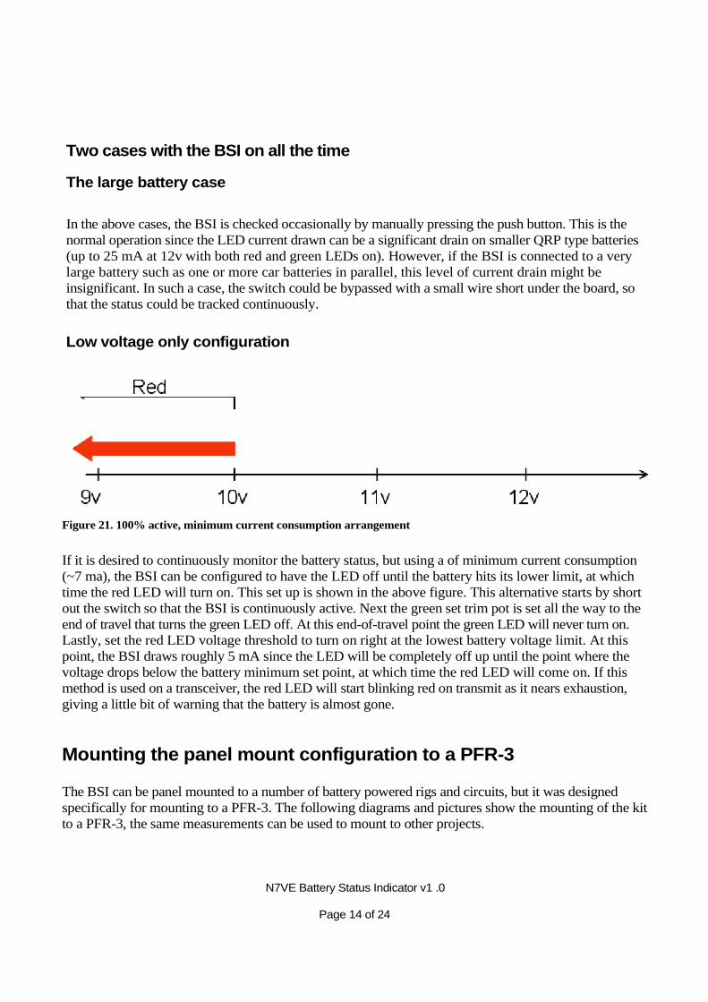
Low voltage only configuration
Figure 21. 100% active, minimum current consumption arrangement
If it is desired to continuously monitor the battery status, but using a of minimum current consumption (~7 ma), the BSI can be configured to have the LED off until the battery hits its lower limit, at which time the red LED will turn on. This set up is shown in the above figure. This alternative starts by short out the switch so that the BSI is continuously active. Next the green set trim pot is set all the way to the end of travel that turns the green LED off. At this end-of-travel point the green LED will never turn on. Lastly, set the red LED voltage threshold to turn on right at the lowest battery voltage limit. At this point, the BSI draws roughly 5 mA since the LED will be completely off up until the point where the voltage drops below the battery minimum set point, at which time the red LED will come on. If this method is used on a transceiver, the red LED will start blinking red on transmit as it nears exhaustion, giving a little bit of warning that the battery is almost gone.
Mounting the panel mount configuration to a PFR-3
The BSI can be panel mounted to a number of battery powered rigs and circuits, but it was designed specifically for mounting to a PFR-3. The following diagrams and pictures show the mounting of the kit to a PFR-3, the same measurements can be used to mount to other projects.
N7VE Battery Status Indicator v1 .0 Page 15 of 24
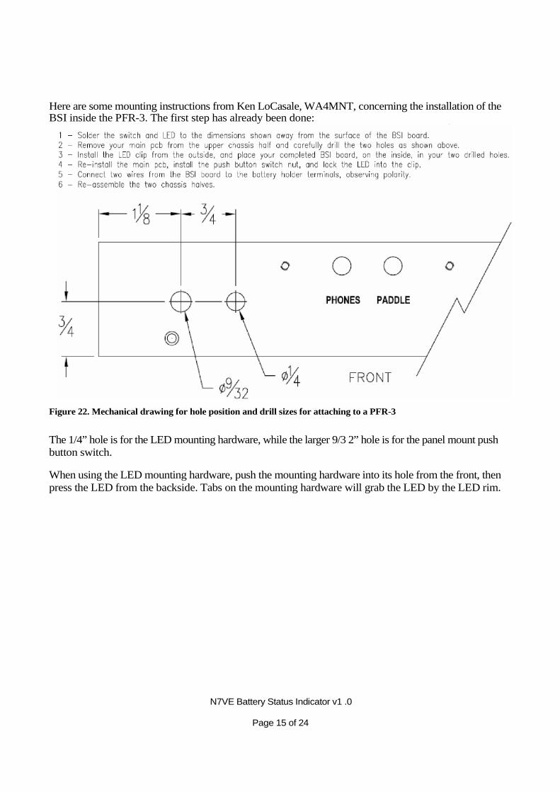
Here are some mounting instructions from Ken LoCasale, WA4MNT, concerning the installation of the BSI inside the PFR-3. The first step has already been done:
Figure 22. Mechanical drawing for hole position and drill sizes for attaching to a PFR-3
The 1/4” hole is for the LED mounting hardware, while the larger 9/3 2” hole is for the panel mount push button switch.
When using the LED mounting hardware, push the mounting hardware into its hole from the front, then press the LED from the backside. Tabs on the mounting hardware will grab the LED by the LED rim.
N7VE Battery Status Indicator v1 .0 Page 16 of 24
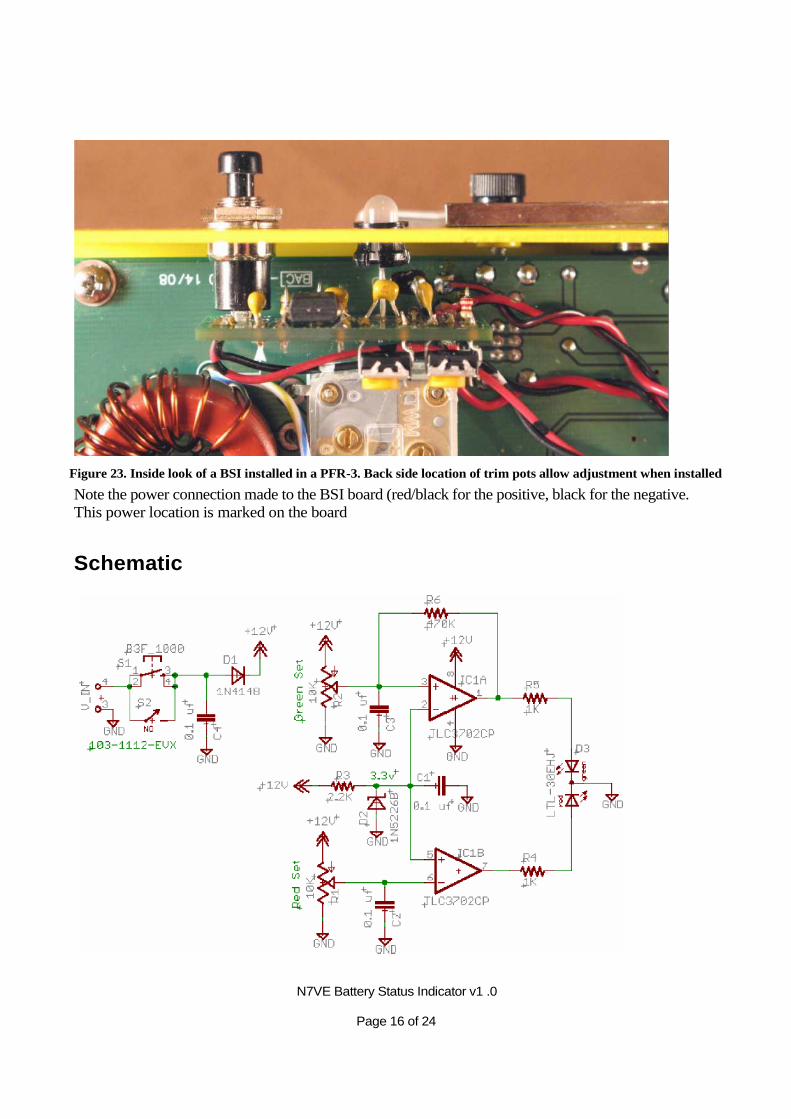
Figure 23. Inside look of a BSI installed in a PFR-3. Back side location of trim pots allow adjustment when installed
Note the power connection made to the BSI board (red/black for the positive, black for the negative. This power location is marked on the board
Schematic
N7VE Battery Status Indicator v1 .0 Page 17 of 24
Appendix A. Battery Specifications
These discharge curves were found by searching the Mouser web sight for particular battery types. Many of the listed batteries have a data sheet that gives these sample discharge curves. If there is a particular battery chemistry that is not listed in this appendix, simply go to either Mouser or Digikey, search for the specific battery type, and pull up a data sheet.
In many cases, a battery pack will be made up of a number of cells such as 6, 8, or 10 AA batteries. Once the “per cell” voltage thresholds are known, these thresholds can be multiplied by 6, 8, or 10 to fit the size of your particular battery pack.
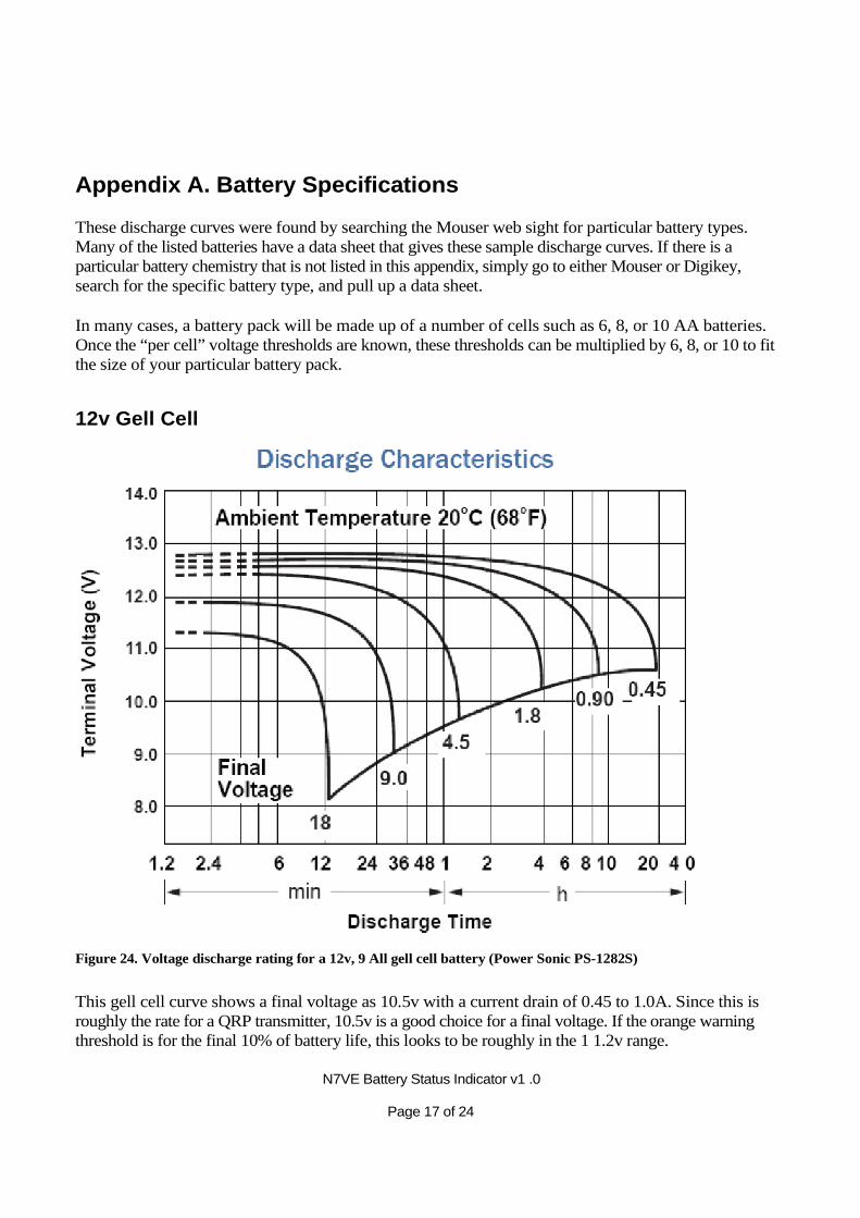
12v Gell Cell
Figure 24. Voltage discharge rating for a 12v, 9 All gell cell battery (Power Sonic PS-1282S)
This gell cell curve shows a final voltage as 10.5v with a current drain of 0.45 to 1.0A. Since this is roughly the rate for a QRP transmitter, 10.5v is a good choice for a final voltage. If the orange warning threshold is for the final 10% of battery life, this looks to be roughly in the 1 1.2v range.
N7VE Battery Status Indicator v1 .0 Page 18 of 24
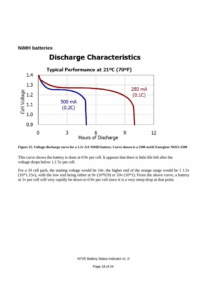
NiMH batteries
Figure 25. Voltage discharge curve for a 1.2v AA NiMH battery. Curve shown is a 2500 mAH Energizer NH15-2500
This curve shows the battery is done at 0.9v per cell. It appears that there is little life left after the voltage drops below 1.1 5v per cell.
For a 10 cell pack, the starting voltage would be 14v, the higher end of the orange range would be 1 1.5v (10*1.15v), with the low end being either at 9v (10*0.9) or 10v (10*1). From the above curve, a battery at 1v per cell will very rapidly be down to 0.9v per cell since it is a very steep drop at that point.
N7VE Battery Status Indicator v1 .0 Page 19 of 24
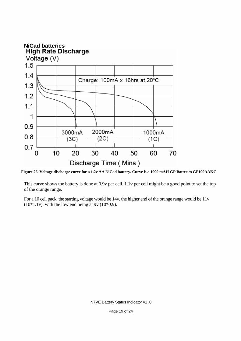
NiCad batteries
Figure 26. Voltage discharge curve for a 1.2v AA NiCad battery. Curve is a 1000 mAH GP Batteries GP100AAKC
This curve shows the battery is done at 0.9v per cell. 1.1v per cell might be a good point to set the top of the orange range.
For a 10 cell pack, the starting voltage would be 14v, the higher end of the orange range would be 11v (10*1.1v), with the low end being at 9v (10*0.9).
N7VE Battery Status Indicator v1 .0 Page 20 of 24
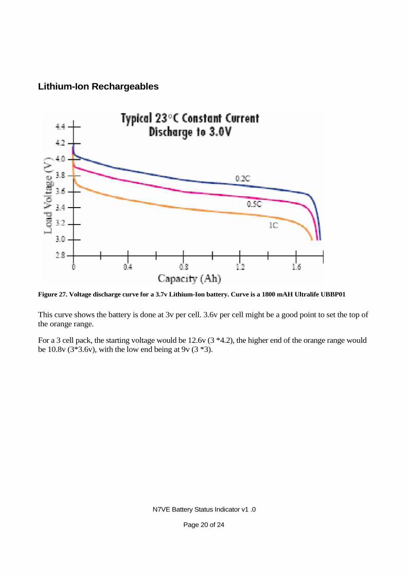
Lithium-Ion Rechargeables
Figure 27. Voltage discharge curve for a 3.7v Lithium-Ion battery. Curve is a 1800 mAH Ultralife UBBP01
This curve shows the battery is done at 3v per cell. 3.6v per cell might be a good point to set the top of the orange range.
For a 3 cell pack, the starting voltage would be 12.6v (3 *4.2), the higher end of the orange range would be 10.8v (3*3.6v), with the low end being at 9v (3 *3).

N7VE Battery Status Indicator v1 .0 Page 21 of 24
Alkaline Non-rechargables
Figure 28. Voltage discharge curve for a 1.5v AA alkaline battery. Curve is a Energizer EN91.
This curve shows the battery is done at 0.8 to 0.9v per cell. 1. 1v per cell might be a good point to set the top of the orange range.
For a 10 cell pack, the starting voltage would be 15v, the higher end of the orange range would be 11v (10*1.1v), with the low end being at 9v (10*0.9) or 8v (10*0.8v).