my opinion this report is sufficient from the perspective...
TRANSCRIPT

I admit that I have read this report and in my opinion this report is sufficient from the
perspective of the scope and quality for award.ing purposes Bachelor of Mechanical
Engineering (Thermal Fluid)
Signature
Supervisor Name
Date

TO IDENTIFY ON THERMODYNAMIC STEAM TRAP F AlLURE
MECHANISM ON HORIZONTAL INSTALLATION.
MOHD NOR HAKIM BlN MOHD TAffi
This report project is submitted to
Faculty of Mechanical Engineering
In partial fulfillment for
Bachelor of Mechanical Engineering (lbermal Fluid)
Faculty of Mechanical Engineering
Kolej Universiti Teknikal Kebangsaan Malaysia
November 2005

I hereby declare that the word or the sentences in this thesis is of my own except for
quotations and summarize which have been acknowledge.
Signature
Writer Name
Date
: .. }.5!:::. .......... . : Mohd Nor Hakim bin Mohd Taib
: /l.f I> J S~J.tl't .).(n !"
II

Ill
ACKNOWLEDGEMENT
ln the name of Allah, The Most Gracious, The Most Merciful. First and
foremost, I thank to Allah for giving me the opportunity to complete my thesis
successfully.
I would like to take this opportunity to express my deepest gratitude towards
Faculty of Mechanical Engineering, Kolej Universiti Teknikal Kebangsaan Malaysia
(KUTKM) and Petronas Penapisan Melaka Sdn. Bhd. (PPMSB) for giving me the
guidance and chance to finish my thesis. Special thanks to Faculty of Mechanical
Engineering Dean, Professor Dr Md Razali b Ayub for his concern and guidance
over student thesis
and
Mr. Mohd lzzat b Mohd Khazar, Mechanical Engineer, Operational
Performance Improvement Unit in PPMSB for his consistent supervision, guidance,
support and encouragement throughout this project
and
Mr Yusmady b Mohamed Arifin, my KUTK.M supervisor who had given his full
commitment and support towards the project
Last but not least, I would like to express my appreciation to my family, all
lecturers, technicians and anybody who get involved during my project for their
continuous patience in supporting and helping me, sharing experience and also the
encouragement throughout this project.

iv
ABSTRACT
After finishing the industrial training in Petronas Penapisan Melaka Sdn Bhd
(PPMSB), writer found that steam trap is a very important device used in steam
system. Steam trap population in PPMSB is approximately 5800 plus. Great numbers
of steam trap used in plant but small in size, make them as though they were
neglected. Steam traps frequently fail but they were not noticed except when they are
leaking. Different brands and types of steam trap being used by different units and
areas in PPMSB plant. For industrial use, every steam trap was designed for
designated reasons but usually being replaced blindly when they failed. Steam traps
affect steam balance, product's temperatures and reduce of water hammering risk.
Due to steam trap failures, PPMSB are losing more than I 00 tonnes per day of steam,
hence losing more than RMIOO,OOO per month. For that reason, deep research should . be done to identify the steam trap failure and try to find the solution because from the
research result, it can help industrial especially have an involvement with steam
generation to increase their profit and reduce operation cost in providing steam.ln
order to do that, early study and literature review of the related field is needed in
order to accomplish this goal. After this step is done, we have to learn how the
internal part of steam trap fail and make comparison the failure of actual steam trap
and simulation sample of steam ttap using CFX 5 Simulation Softwate. This
software is one of the frequently used software in research industry for
Computational Fluid Dynamic (CFD). In addition, we have to fmd a solution how to
overcome this failure by doing the analysis and give a suitable recommendation.
v
ABSTRAK
Setelab menjalani latiban industri di Petronas Penapisan Melaka Sdn Bhd,
penulis mendapati bahawa perangkap stim adalah satu peraJatan yang amat penting
digunakan di dalam sistem stim. Populasi untuk perangk:ap stim di PPMSB
menjangkau sehingga lebih 5800 buah. Satujumlah yang begitu banyak digunakan di
dalam loji tetapi sering diabaikan kerana saiznya yang kecil. Perangkap stim juga
sering mengalami kerosakan tetapi tidak diketahui melainkan setelah ianya
bocor.Pelbagai jenama dan jenis perangkap stim digunakan di dalam pelbagai unit
dan kawasan loji PPMSB. Setiap perangk:ap stim direka bentuk dengan fungsi
tersendiri tetapi apabila ia mengalami kerosakan, selalunya diganti dengan begitu
sahaja tanpa meneliti keadaan sistem yang digunakan. Perangkap stim juga
mempengaruhi keseimbangan stim di dalam sistem, suhu produk dan juga . menurunkan risiko penukul air.Disebabkan oleh kegagalan perangkap stim, PPMSB
mengalami kehilangan stim sehingga 100 tan sehari menyebabkan kerugian
menjangkau sehingga RM I 00,000 sebulan.Oleh sebab itu, kajian yang Jebih
mendalarn perlu dijalankan untuk mengenal pasti punca sebenar kegagalan
perangkap stim dan mencari langk:ah yang sesuai untuk mengatasinya kerana dengan
hasil kajian yang diperolehi ianya dapat membantu pelbagai pihak terutamanya yang
terlibat di dalarn penjanaan stim untuk meningkatkan keuntungan syarikat dan
menurunkan kos operasi menghasilkan stim.Untuk melaksanakannya, pencarian
mak:Jumat terhadap bidang yg berkaitan perlu dilakukan. Setelah itu, kajian
bagaimana perangk:ap stim rosak perlu dilakukan dan membuat perbandingan antara
contoh sebenar perangkap stim dengan contoh simulasi dengan menggunakan
perisian simulasi CFX 5. Perisian ini merupakan perisisian yang sering digunakan di
dalam bidang Dinarnik Bendalir Berkomputer. Selain itu, kita juga perlu mencari
penyelesaian untuk mengatasi masalah ini dan memberikan cadangan yang sesuai.

VI
LIST OF CONTENT
CHAPTER TITLE PAGE
I INTRODUCTION 1
1.1 Introduction ofProject
1.2 Purpose of the Study 2
1.3 Problem Statement 2
1.4 Focus 3
1.5 Objectives 3
1.6 Scope 3
1.7 Outline Thesis 4
2 LITERATURE REVIEW 5
2.1 Introduction of Steam System 5
2.2 Types of Steam 6
2.3 Steam System Operation 7
2.4 The Need for Steam Trap in Steam System 10
2.5 The Classification of Steam Trap 12
2.6 Operating Conditions of Steam Trap 19
2.7 Introduction to Thermodynamic Steam Trap 24

vii
3 METHODOLOGY 26
3.1 Steam Trap Test Equipment 26
3.2 Test Preparation 27
3.3 Flow Chart of Methodology 28
4 RESULTS AND DISCUSSIONS 29
4.1 Definition of Critical Point 29
4.2 Actual Sample of Steam Trap 31
4.3 Steam Trap Modeling 36
4.4 Simulation Result of Steam Trap for Open Disc 37
4.5 Simulation Result of Steam Trap for Close Disc 43
5 CONCLUSION AND RECOMMENDATIONS 50
6 REFERENCES 53
7 APPENDICES 55

USTOFTABLE
TABLE NO. TITLE
1-1 Types of Steam
2-1 Different Trap Types and Their Classifications
PAGE
7
18
Vlll

IX
UST OF FIGURE
FIGURE NO TITLE PAGE
2-1 Steam System Schematic 10
2-2 Inverted Bucket Steam Trap 13
2-3 Bimetallic Steam Trap 14
2-4 Bellows Steam Trap 15
2-5 Float and Thermostatic Steam Trap 16
2-6 Disc Steam Trap 17
2-7 Common Steam Trap Arrangement 20
4-1 Internal View of Thermodynamic Steam Trap 30
4-2 Actual Sample ofThennodynamic Steam Trap . (Side View) 31
4-3 Top View of Actual Steam Trap in
Good Condition 34
4-4 Top View of Actual Steam Trap in
Bad Condition ( 1 ). 35
4-5 Top View of Actual Steam Trap in
Bad Condition (2). 35
4-6 Steam Trap Sample
(Assembly of Body, Cap and Strainer Cap) 36
4-7 Side View of Simulation Sample
(Disc Open) for Velocity 37
4-8 Isometric View of Simulation Sample
(Disc Open) for Velocity 38

X
4-9 Side View of Simulation Sample
(Disc Open) for Pressure 39
4-10 Isometric View of Simulation Sample
(Disc Open) for Pressure 40
4-11 Isometric View of Critical Point in Steam Trap
(Disc Open) 41
4-12 Side View of Critical Point in Steam Trap
(Disc Open) 42
4-13 Side View of Simulation Sample
(Disc Close) for Velocity 43
4-14 Isometric View of Simu.lation Sample
(Disc Close) for Velocity 44
4-15 Side View of Simulation Sample
(Disc Close) for Pressure 45
4-16 Isometric View of Simu.lation Sample
(Disc Close) for Pressure 46
4-17 Isometric View of Critical Point in Steam Trap
(Disc Close) 47
4-18 Side View of Critical Point in Steam Trap
(Disc Close) 48

NOMENCLATURE
HP
MP
LP
LLP
PERMATA
CFD
OK
FO
FC
FOP
OS
OFF
UNK
N/A
PPMSB
LIST OF NOMENCLATURE
DEFINITION
High Pressure
Medium Pressure
Low Pressure
Low Low Pressure
Petronas Management Training
Computational Fluid Dynamic
Normally Operating
Failed Open
Failed Close
Failed Open Partial
Out of Service
Off
Unknown
Not Accessible
Petronas Penapisan Melaka Sdn Bhd
xi

APPENDICES
A
B
c
LIST OF APPENDICES
TITLE PAGE
Figure of Wave Profile of Water Hammering 55
CFX 5 Simulation Software Detail Information 57
Detail Drawing of Steam Trap 70
XII

CHAPTER!
INTRODUCTION
1.1 Introduction of Project
Condensate is formed whenever steam gives up its enthalpy of evaporation
(latent heat). The proper removal of condensate from steam plant of all types is vitaJ
if the plant is to work efficiently and this operation is commonly performed by a
steam trap.
Frequent causes bf unsatisfactory condensate drainage include the choice of
the wrong type of steam trap for the application, the use of a trap that is incorrectly
sized for the load and pressure conditions and bad installation. Because any of these
factors can seriously reduce plant output, it is worth spending some time studying
how steam traps work and their application.
A steam trap is a self-contained automatic valve which automatically drains
the condensate from a steam-containing enclosure while remaining closed to live
steam. Some traps pass live steam at a controlled rate. Most traps also pass air and
other non condensate gases while remaining closed to live steam.
The difference between condensate and steam is sensed in several ways. One
group of traps detects the difference in density, another group reacts to a difference
in temperature, and a third relies on the difference in flow characteristics.

2
Efforts and methods implementation needs to be considered are; study on the
steam trap characteristics, design and how it works in real application in industry.
The methodology uses are theoretical and simulation. The role of theoretical method
in this study is to get the beginning data of steam system used in industry, frequent
used of steam trap in industry and also type of failure happen on steam trap in
industry. Meanwhile, the simulation method is to see the change and to compare
result with theoretical method. The type of simulation use is CFX-5 to get the
beginning result.
1.2 Purpose of the Study
The purpose of this study is to learn how the internal parts of thermodynamic steam
trap fail. CFX-5 simulation software is used in order to implement the task. Steam
trap internal part needed to be emphasis with perfect sizing to investigate the part
that gives an effect on steam trap efficiency.
1.3 Problem Statement
Thermodynamic steam trap have a frequent failure in the horizontal position. This
failure applies to ali type of pressure; High Pressure Steam (HP Steam), Mediwn
Pressure Steam (MP Steam) and Low Pressure Steam (LP Steam).

3
1.4 Focus
The focus of this study is at the internal part of thermodynamic steam trap.
The component need to be emphasis is when steam flow into inlet of thermodynamic
steam trap and moving around the steam trap, critical point of steam trap should be
analyzed in order to increase its efficiency.
1.5 Objectives
The objectives of this study are as follows:
l. To learn how the steam traps functioning and operate in steam system.
2. To learn how the internal parts of thermodynamic steam trap fail
3. To compare the failure of actual sample and simulation sample of steam trap
4. To find a solution how to overcome the failure of steam trap.
In order to comJllete the task, need to study on thermodynamic steam trap
internal part and doing simulation by using CFX-5 Simulation Software. It is
intended to know the involved basic principle such as principle of steam trap, how it
works and early study on steam system used in industry.
1.6 Scope
The scope of this thesis is to learn how steam trap functioning and operational
in steam system. To do that, early study and literature review of the related field is
needed in order to accomplish this thesis. After this step is done, we have to learn
how the internal part of steam trap fail and make comparison the failure of actual
steam trap and simulation sample of steam trap using CFX 5 Simulation Software.
This software is one of the frequently used software in research industry for

4
Computational Fluid Dynamic (CFD). In addition, we have to find a solution how to
overcome this failure by doing the analysis and give a suitable recommendation.
1. 7 Outline Thesis
In chapter 2, it is explained about the literature review that has been done.
There are many title of thesis by earlier researcher on how to improve the
performance of steam trap. Within this research, there are many factors that influence
the steam trap efficiency such as quality of steam used, maintenance of steam trap
and type of steam trap used in industry.
In chapter 3, this part explains about method used in order to solve the
problem that involve in this research. Simulator program is used to get the result on
the experiment. The type of simulator used is CFX-5. Meanwhile, steam trap used is
thermodynamic steam trap and the research is on the internal part of thermodynamic
steam trap. It also expla.ins about expected resuJt that can be achieved. The result
possibility is the critical point in internal part of steam trap when steam is flowing
through it can be found.
[n chapter 4, the result and discussion of overaU simulation will be explained
in full detail about the main founding during simulation.
[n chapter 5, the conclusion and recommendations of this thesis will be
explained in order to finalize this thesis. As a conclusion, this research will give big
impact to industry that is using steam trap in order to increase the profit of company
and reduce of steam loss.

5
CHAPTER2
LITERATURE REVIEW
2.1 Introduction of Steam System
There are three principal fonns of energy used in industrial processes:
electricity, direct-fired heat, and steam. Electricity is used in many different ways,
including mechanical drive, heating, and electrochemical reactions. Direct-frred
energy directly transfers the heat of fuel combustion to a process. Steam provides
process heating, pressure control, mechanical drive, component separation, and is a
source of water for many, process reactions.
Steam has many performance advantages that make it an indispensable means
of delivering energy. These advantages include low toxicity, ease of transportability,
high efficiency, high heat capacity, and low cost with respect to the other
alternatives. Steam holds a significant amount of energy on a unit mass basis
(between 1,000 and 1,250 Btu/lb) that can be extracted as mechanical work through a
turbine or as heat for process use. Since most ofthe heat content of steam is stored as
latent heat, large quantities of heat can be transferred efficiently at a constant
temperature, which is a useful attribute in many process heating applications.
Steam is also used in many direct contact applications. For example, steam is
used as a source of hydrogen in steam ethane reforming, which is an important
process for many chemical and petroleum refining applications. Steam is also used to

6
control the pressures and temperatures of many chemical processes. Other significant
applications of steam are to strip contaminants from a process fluid, to facilitate the
fractionation of hydrocarbon components, and to dry all types of paper products.
(Bioom.D. et al, 2001),
2.2 Types of Steam
There are four types of steam systems:
1. High Pressure Steam (HP)
2. Medium Pressure Steam (MP)
3. Low Pressure Steam (LP)
4. Low Low Pressure Steam (LLP)

7
[TYPE DESCRIPTION
~Steam • Generated by boilers
Used to drive steam turbines
• Provide heat for Heat Exchangers
• Temperature range 375-395 degree C
IMP Steam • Produced by passing the HP steam through Desuperheater
• Temperature range 207-220 degree C
• Used by Reboilers
ILP Steam . Produced by flashing condensate from Reboilers that used MP steam
Used in other Reboilers, Deaerator and cold flare stack
~LP Steam • Produced by flashing condensate from Reboilers that used LP steam
• Used in different heaters, vaporizer and other Reboilers
Table l-2: Types of Steam
(Table is courtesy ofPERMA TA (2002), Basic Utilities Operation)
2.3 Steam System Operation
Four important categories need to be discussing in steam system components
and ways to enhance steam system performance: generation, distribution, end use,
and recovery. These four areas follow the path of steam as it leaves the boiler and
returns via the condensate return system. (Marina L.D. et al, 2002)

8
2.3.1 Generation
Steam is generated in a boiler or a heat recovery steam generator by
transferring the heat of combustion gases to water. When water absorbs enough heat,
it changes phase from liquid to steam. [n some boilers; a superheater further
increases the energy content of the steam. Under pressure, the steam then flows from
the boiler or steam generator and into the distribution system. (Bloom D. et al, 2001)
2.3.2 Distribution
The distribution system carries steam from the boiler or generator to the
points of end use. Many distribution systems have several take-off lines that operate
at different pressures. These distribution lines are separated by various types of
isolation valves, pressure regulating valves, and, sometimes, backpressure turbines.
A properly performing distribution system delivers sufficient quantities of high
quality steam at the right pressures and temperatures to the end uses. Effective
distribution system performance requires proper steam pressure balance, good
condensate drainage, adequate insulation, and effective pressure regulation. (Bloom
D. et al, 2001)
2.3.3 End Use
There are many different end uses of steam. Examples of steam's diverse uses
include process heating, mechanical drive, moderation of chemical reactions, and
fractionation of hydrocarbon components. Common steam system end-use equipment
includes heat exchangers, turbines, fractionating towers, strippers, and chemical
reaction vessels. In a heat exchanger, the steam transfers its latent heat to a process
fluid . The steam is held in the heat exchanger by a steam trap until it condenses, at

9
which point the trap passes the condensate into the condensate return system. In a
turbine, the steam transforms its energy to mechanical work to drive rotating
machinery such as pumps, compressors, or electric generators. In fractionating
towers, steam facilitates the separation of various components of a process fluid. In
stripping applications, the steam pulls contaminants out of a process fluid. Steam is
also used as a source of water for certain chemical reactions. In steam methane
reforming, steam is a source of hydrogen. (Bloom D. et al, 2001)
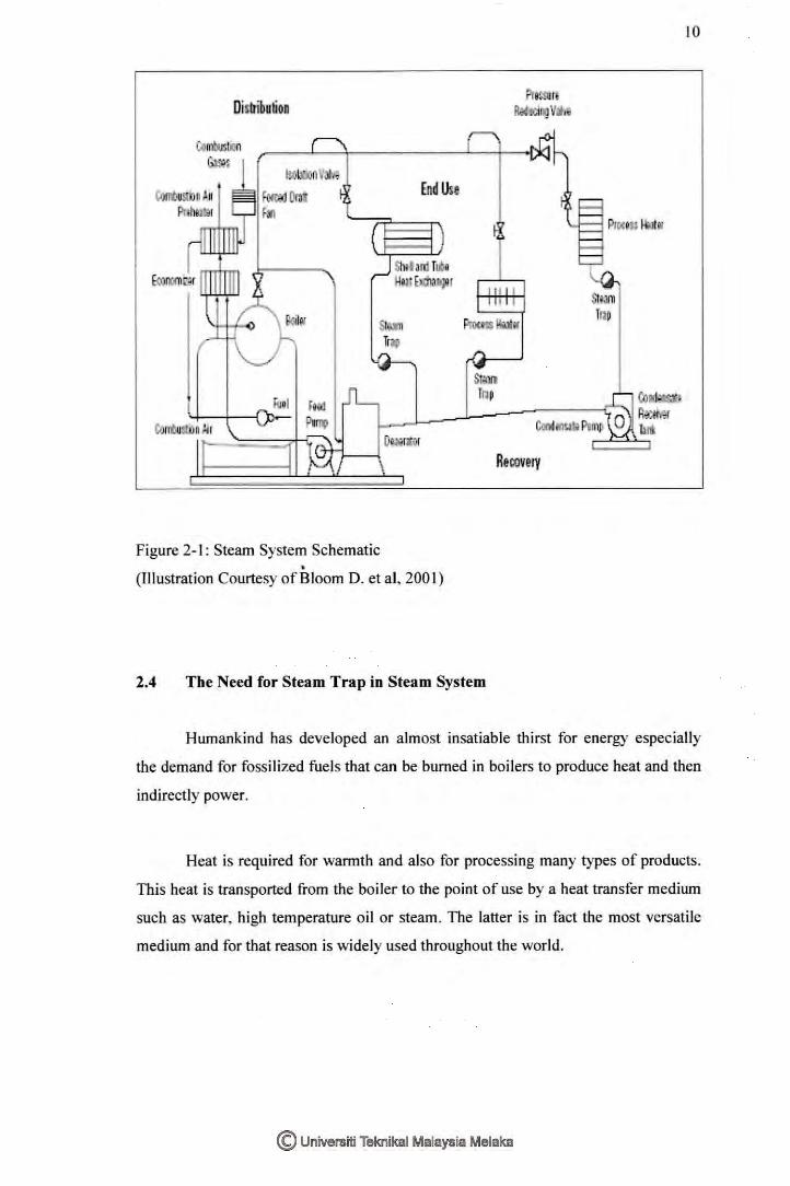
2.3.4 Recovery
The condensate return system sends the condensate back to the boiler. The
condensate is returned to a collection tank. Sometimes the makeup water and
chemicals are added here while other times this is done in the deaerator. From the
collection tank the condensate is pumped to the deaerator, which strips oxygen and
non-condensable gases. The boiler feed pumps increase the feed water pressure to
above boiler pressure and inject it into the boiler to complete the cycle. Figure 2-1 . provides a general schematic description of the four principal areas of a steam
system. (Bloom D. et al,2001)
Distribution
End Use
Stm Trap
Contu::W II ) II
Recovery
Figure 2-1: Steam System Schematic I
(TIIustration Courtesy of Bloom D. et al, 200 I)
2.4 The Need for Steam Trap in Steam System
Stm Tnp
10
Humankind has developed an almost insatiable thirst for energy especially
the demand for fossilized fuel s that can be burned in boilers to produce heat and then
indirectly power.
Heat is required for warmth and also for processing many types of products.
This heat is transported from the boiler to the point of use by a heat transfer medium
such as water, high temperature oil or steam. The latter is in fact the most versatile
medium and for that reason is widely used throughout the world.

11
Steam is generated in the boiler and conveyed through piping to the steam
using equipment. However in spite of the fact that the steam pipe work is usually
well insulated to prevent the loss of heat, some heat will be radiated from the piping.
Steam traveling along the pipe work will transfer some of the heat is carrying to the
wall of the pipe to make up the losses due to radiation and in so doing some of the
system will condense forming condensate (hot water) in the bottom of the pipe.
If this condensate were allowed to remain in the pipe, it would both extract
more heat from the steam and also gradually fill up the pipe, blocking the passage of
steam with disastrous consequences. What is therefore required is a simple automatic
device that will allow such condensate to drain from the pipe without allowing steam
to escape.
Such a device is known as a steam trap and its importance in maintaining the
safety and efficiency of the steam system should not be underestimated. Similarly
when steam finally enters the equipments, heat is transferred through the wall to the
fluid or product being h~ated. As the steam is gives up its heat it condenses, the
condensate so formed beginning to collect within the steam space of the equipment.
Like the steam pipe work, this condensate should not be allowed to remain,
otherwise the process of heat transfer would slow down and eventually cease
altogether.
Once again, therefore, the simple automatic steam trap must be used to drain
away the condensate without any steam escaping. Steam traps are however required
to carry out one further function that is not at first apparent. When a steam system is
shut down air enters the pipe work to occupy the space left by the condensing steam.
Upon start up this air is pushed ahead of the steam to the far point of the pipe work
system and also into the steam using equipment. It therefore reaches the drain outlets
to which the steam traps are connected. Steam trap must also then be capable of
discharging air and non-condensable gases for otherwise if these were allowed to