mxb-360 360,000 btu boiler - lanair · mxb-360 360,000 btu boiler installation and operating...
TRANSCRIPT
MXB-360360,000 BTU BOILER
Installation and Operating Instructions
®
Lanair Waste Oil Heaters & Boilers4109 Capital Circle
Janesville, Wisconsin 53546608-752-1601
www.lanair.com
®BEFORE YOU BEGIN INSTALLATION...
Read and understand this manual completely before beginning installation.
Code Requirements
Installation must comply with all state, local and utility codes, laws, regulations and ordinances and CSA standardB139. When required, installations must conform to A.S.M.E. safety code for controls and safety devices for automatically fired boilers No. CSD-1.
All electrical wiring must be done by a licensed electrician in accordance with the National Electrical codes latestedition and all state and local codes.
Rules for Safe Installation and Operation
1. This boiler is for commercial and industrial use only. This unit is not intended for residential use.
2. This boiler must be installed by a licensed HVAC/Hydronic contractor. Installer should be trained and thoroughlyfamiliar with the installation and operation of oil-fired boilers.
3. Read this owner's manual and the rules for safe operation carefully. Failure to follow the rules of safe operationand the instructions could cause a malfunction of the boiler and result in death, serious bodily injury, and/orproperty damage.
4. Locate the boiler as close to the chimney as practical. Observe the minimum clearances outlined in Fig. 1,page 8. Remember to allow room for the boiler door to open with the burner mounted.
5. Make sure that the surface on which the boiler is to be installed is capable of supporting the weight of the boil-er, burner, and all other equipment supported by that surface.
6. A boiler pad is strongly recommended . This pad is to be made of poured concrete. It should be at least 4 inchesthick and should cover the entire area underneath the boiler (not just the legs).
7. Make sure the location chosen for the boiler will provide adequate air for combustion and ventilation (see Fig. 2,page 9). Also make sure that fuel and electrical requirements can be satisfied at the boiler location chosen.
8. The heating system design shall not permit the boiler's return water temperature to be lower than 130˚F for asignificant period of time. This will prevent fire side corrosion and insure a long life expectancy for your boiler.
9. Check to make sure you have all the required components needed for proper installation and operation.
10. Check each component for visible damage. If you find a damaged component, contact a Lanair ServiceRepresentative for a replacement. Do not install broken or damaged parts.
11. This boiler is designed to provide economically and environmentally friendly disposal of waste oil. Due to thenature of the fuel used, this boiler should not be relied upon as the sole source of heat.
12. Read and understand the warranty. Fill out the enclosed warranty card and return within 10 days of purchase.
QUESTIONS?... Contact Customer Service at 1-800-753-1601 M-F 8:00 am- 4:30 pm CST2
MXB 360360,000 BTU BOILERInstallation and Operating Instructions
Table of Contents:Code Requirements and Rules For Safe Installation and Operation . . . . . . . . . . . . . . . . page 2
Sec. 1 General Specifications . . . . . . . . . . . . . . . . . . . . . . . . . . . . . . . . . . . . . . . . . . . . . . . . . . . . . . . . . . . . . . . . . . . page 4
Sec. 2 Typical Boiler Room Layout . . . . . . . . . . . . . . . . . . . . . . . . . . . . . . . . . . . . . . . . . . . . . . . . . . . . . . . . . . . . . page 8
Sec. 3 Boiler Room Air Requirements . . . . . . . . . . . . . . . . . . . . . . . . . . . . . . . . . . . . . . . . . . . . . . . . . . . . . . . . . . page 8
Sec. 4 Chimney/Vent System . . . . . . . . . . . . . . . . . . . . . . . . . . . . . . . . . . . . . . . . . . . . . . . . . . . . . . . . . . . . . . . . . . . page 10
Sec. 5 Draft . . . . . . . . . . . . . . . . . . . . . . . . . . . . . . . . . . . . . . . . . . . . . . . . . . . . . . . . . . . . . . . . . . . . . . . . . . . . . . . . . . . . . . . page 11
Sec. 6 Fuel Supply Tank Piping Installation . . . . . . . . . . . . . . . . . . . . . . . . . . . . . . . . . . . . . . . . . . . . . . . . . . . . page 12
Sec. 7 Fuel Supply Pump/Piping . . . . . . . . . . . . . . . . . . . . . . . . . . . . . . . . . . . . . . . . . . . . . . . . . . . . . . . . . . . . . . . page 13
Sec. 8 Typical Boiler Piping . . . . . . . . . . . . . . . . . . . . . . . . . . . . . . . . . . . . . . . . . . . . . . . . . . . . . . . . . . . . . . . . . . . . . . page 15
Sec. 9 Boiler Installation . . . . . . . . . . . . . . . . . . . . . . . . . . . . . . . . . . . . . . . . . . . . . . . . . . . . . . . . . . . . . . . . . . . . . . . . . page 16
Sec. 10 Boiler Controls and Accessory Location . . . . . . . . . . . . . . . . . . . . . . . . . . . . . . . . . . . . . . . . . . . . . . . . page 20
Sec. 11 Burner Installation . . . . . . . . . . . . . . . . . . . . . . . . . . . . . . . . . . . . . . . . . . . . . . . . . . . . . . . . . . . . . . . . . . . . . . . . page 21
Sec. 12 Electrical Connections/Wiring Diagram . . . . . . . . . . . . . . . . . . . . . . . . . . . . . . . . . . . . . . . . . . . . . . . . page 22
Sec.13 Compressed Air Installation . . . . . . . . . . . . . . . . . . . . . . . . . . . . . . . . . . . . . . . . . . . . . . . . . . . . . . . . . . . . . page 24
Sec.14 Controls . . . . . . . . . . . . . . . . . . . . . . . . . . . . . . . . . . . . . . . . . . . . . . . . . . . . . . . . . . . . . . . . . . . . . . . . . . . . . . . . . . . page 25
Sec.15 Start Up Procedure . . . . . . . . . . . . . . . . . . . . . . . . . . . . . . . . . . . . . . . . . . . . . . . . . . . . . . . . . . . . . . . . . . . . . . . page 26
Sec.16 Priming Fuel Pump . . . . . . . . . . . . . . . . . . . . . . . . . . . . . . . . . . . . . . . . . . . . . . . . . . . . . . . . . . . . . . . . . . . . . . . page 28
Sec.17 Flame Adjustment . . . . . . . . . . . . . . . . . . . . . . . . . . . . . . . . . . . . . . . . . . . . . . . . . . . . . . . . . . . . . . . . . . . . . . . page 29
Sec.18 Maintenance Schedule / Service Adjustments . . . . . . . . . . . . . . . . . . . . . . . . . . . . . . . . . . . . . . . . page 31
Sec.19 Troubleshooting . . . . . . . . . . . . . . . . . . . . . . . . . . . . . . . . . . . . . . . . . . . . . . . . . . . . . . . . . . . . . . . . . . . . . . . . . . page 40
Sec.20 Warranty Certificate . . . . . . . . . . . . . . . . . . . . . . . . . . . . . . . . . . . . . . . . . . . . . . . . . . . . . . . . . . . . . . . . . . . . . . page 42
Sec.21 Burner Reference Diagram . . . . . . . . . . . . . . . . . . . . . . . . . . . . . . . . . . . . . . . . . . . . . . . . . . . . . . . . . . . . . . page 43
Visit our website at: www.lanair.com
QUESTIONS?... Contact Customer Service at 1-800-753-1601 M-F 8:00 am- 4:30 pm CST4
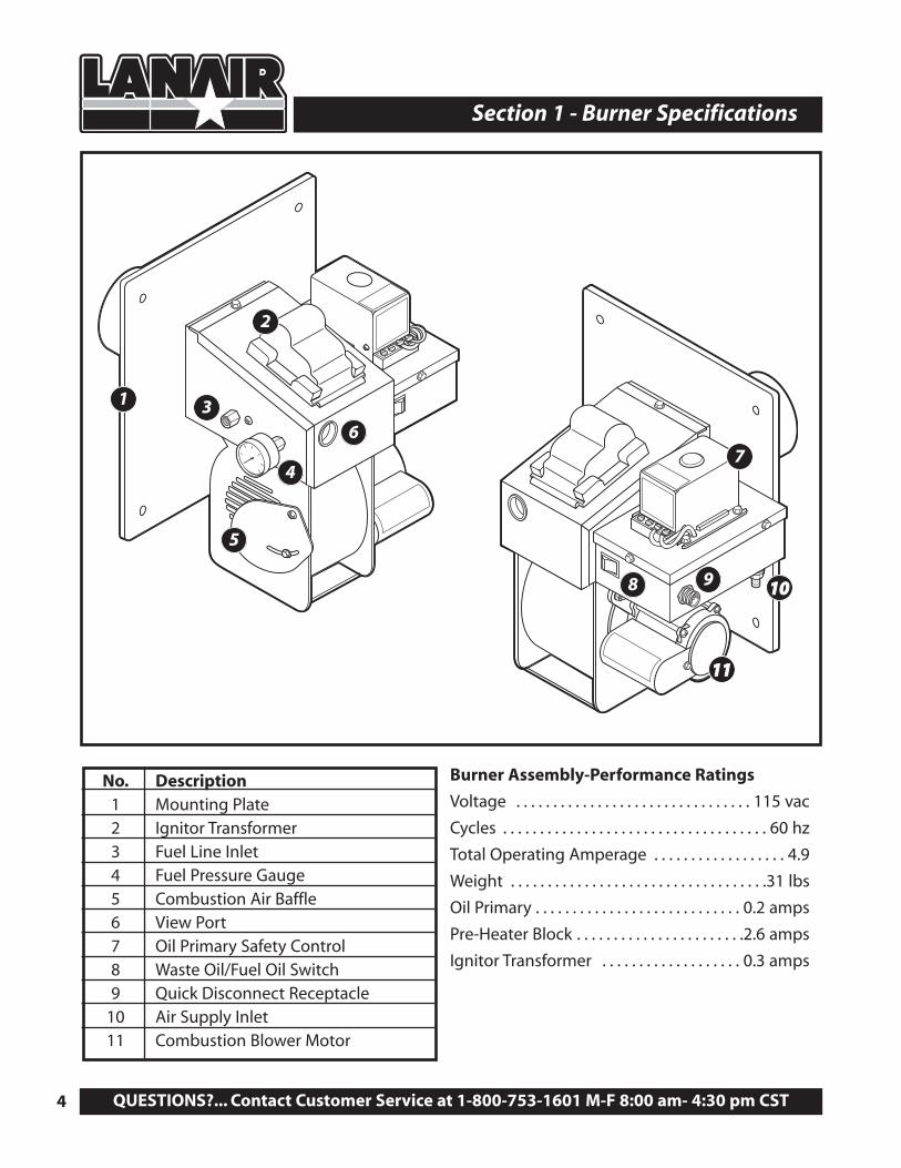
Section 1 - Burner Specifications
1 3
4
2
6
5
8 9 1010
7
1111
No. Description1 Mounting Plate2 Ignitor Transformer3 Fuel Line Inlet4 Fuel Pressure Gauge5 Combustion Air Baffle6 View Port7 Oil Primary Safety Control8 Waste Oil/Fuel Oil Switch9 Quick Disconnect Receptacle
10 Air Supply Inlet11 Combustion Blower Motor
Burner Assembly-Performance Ratings
Voltage . . . . . . . . . . . . . . . . . . . . . . . . . . . . . . . . 115 vac
Cycles . . . . . . . . . . . . . . . . . . . . . . . . . . . . . . . . . . . . 60 hz
Total Operating Amperage . . . . . . . . . . . . . . . . . . 4.9
Weight . . . . . . . . . . . . . . . . . . . . . . . . . . . . . . . . . . .31 lbs
Oil Primary . . . . . . . . . . . . . . . . . . . . . . . . . . . . 0.2 amps
Pre-Heater Block . . . . . . . . . . . . . . . . . . . . . . .2.6 amps
Ignitor Transformer . . . . . . . . . . . . . . . . . . . 0.3 amps
Visit our website at: www.lanair.com 5
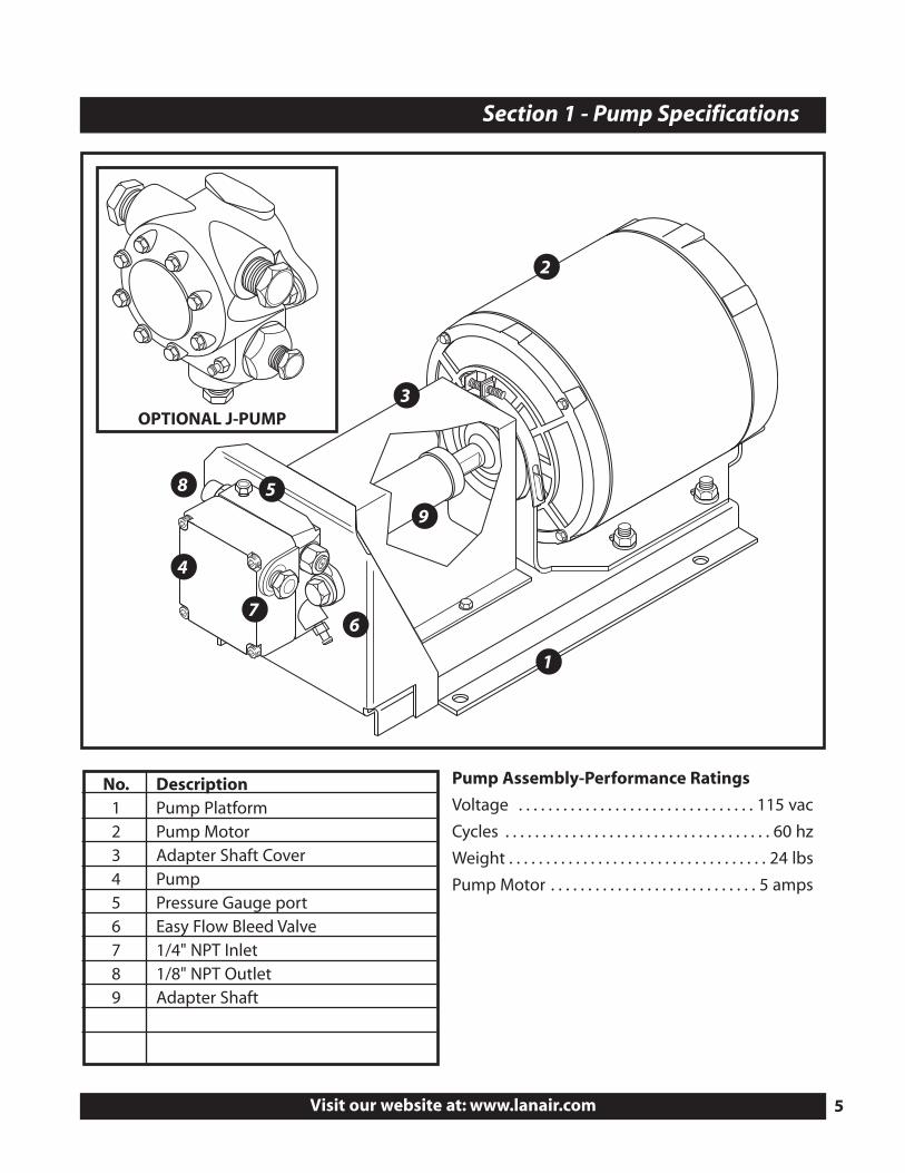
Section 1 - Pump Specifications
No. Description1 Pump Platform2 Pump Motor3 Adapter Shaft Cover4 Pump5 Pressure Gauge port6 Easy Flow Bleed Valve7 1/4" NPT Inlet8 1/8" NPT Outlet9 Adapter Shaft
Pump Assembly-Performance Ratings
Voltage . . . . . . . . . . . . . . . . . . . . . . . . . . . . . . . . 115 vac
Cycles . . . . . . . . . . . . . . . . . . . . . . . . . . . . . . . . . . . . 60 hz
Weight . . . . . . . . . . . . . . . . . . . . . . . . . . . . . . . . . . . 24 lbs
Pump Motor . . . . . . . . . . . . . . . . . . . . . . . . . . . . 5 amps
2
1
3
4
5
6
8
9
7
OPTIONAL J-PUMP
QUESTIONS?... Contact Customer Service at 1-800-753-1601 M-F 8:00 am- 4:30 pm CST6
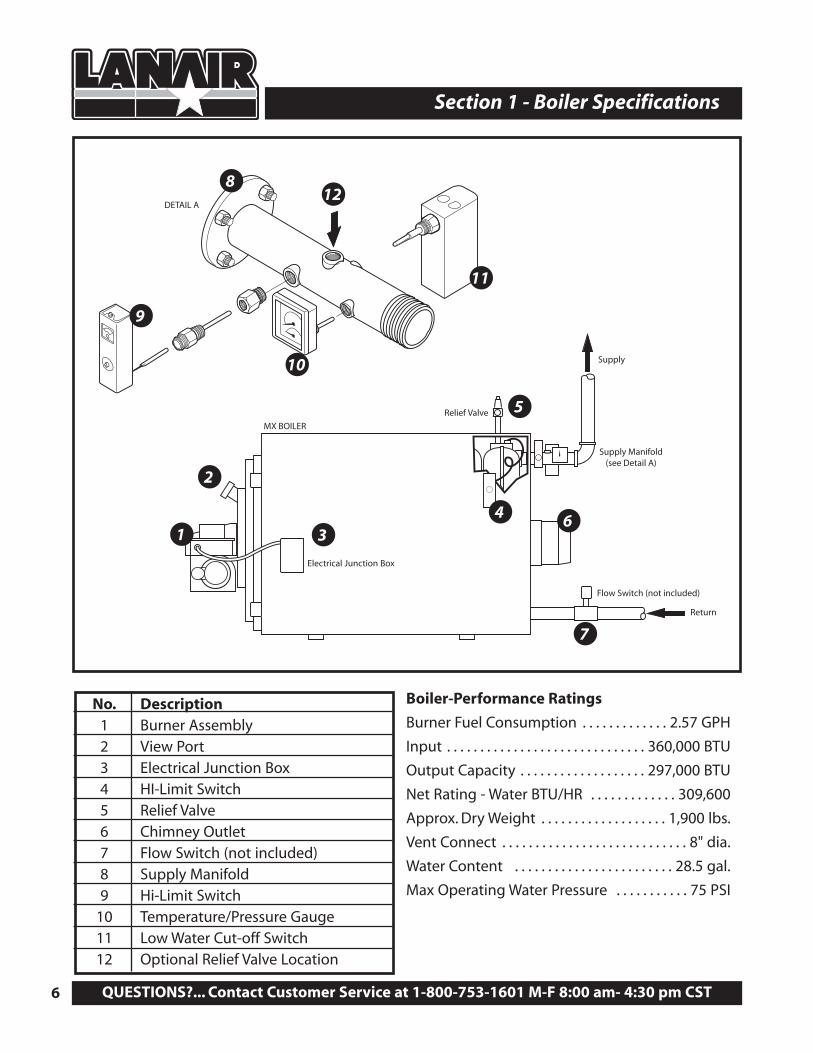
Section 1 - Boiler Specifications
Supply
Relief Valve
Flow Switch (not included)
Return
Supply Manifold(see Detail A)
MX BOILER
DETAIL A
No. Description1 Burner Assembly2 View Port3 Electrical Junction Box4 HI-Limit Switch5 Relief Valve6 Chimney Outlet7 Flow Switch (not included)8 Supply Manifold9 Hi-Limit Switch
10 Temperature/Pressure Gauge11 Low Water Cut-off Switch12 Optional Relief Valve Location
Boiler-Performance Ratings
Burner Fuel Consumption . . . . . . . . . . . . . 2.57 GPH
Input . . . . . . . . . . . . . . . . . . . . . . . . . . . . . . 360,000 BTU
Output Capacity . . . . . . . . . . . . . . . . . . . 297,000 BTU
Net Rating - Water BTU/HR . . . . . . . . . . . . . 309,600
Approx. Dry Weight . . . . . . . . . . . . . . . . . . . 1,900 lbs.
Vent Connect . . . . . . . . . . . . . . . . . . . . . . . . . . . . 8" dia.
Water Content . . . . . . . . . . . . . . . . . . . . . . . . 28.5 gal.
Max Operating Water Pressure . . . . . . . . . . . 75 PSI
1 34
5
6
7
11
8
9
10
12
2
Electrical Junction Box
Visit our website at: www.lanair.com 7
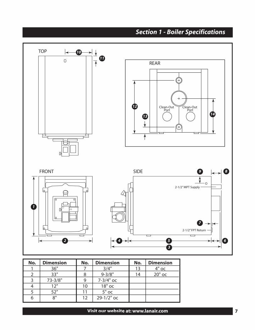
Section 1 - Boiler Specifications
2-1/2” MPT Supply
2-1/2” FPT Return
Clean-Out Port
Clean-Out Port
1
2
3
54 6
7
9 8
13
12
14
10
11
FRONT SIDE
REAR
TOP
No. Dimension1 36"2 33"3 73-3/8"4 12"5 52"6 8"
No. Dimension7 3/4"8 9-3/8"9 7-3/4" oc
10 18" oc11 5" oc12 29-1/2" oc
No. Dimension13 4" oc14 20" oc
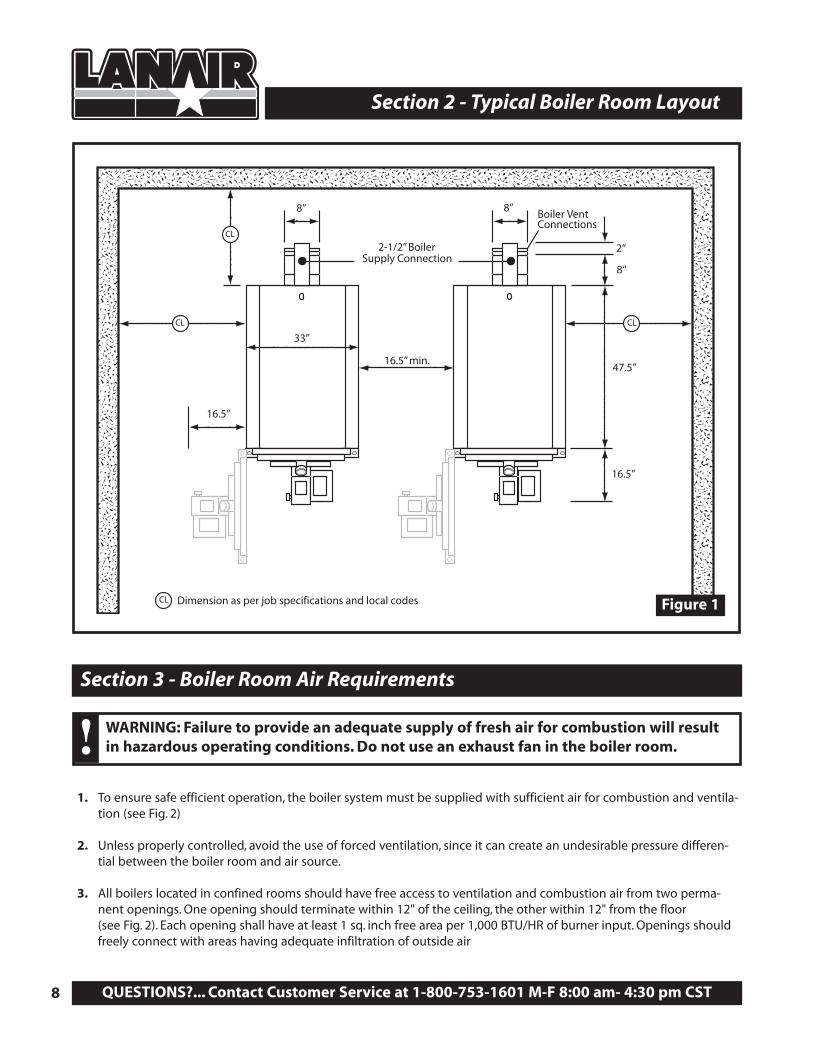
2-1/2” BoilerSupply Connection
CLCL
CL
8“
2“
16.5”
16.5” min.
8” 8”
16.5”
33”
47.5”
CL Dimension as per job specifications and local codes
Boiler VentConnections
QUESTIONS?... Contact Customer Service at 1-800-753-1601 M-F 8:00 am- 4:30 pm CST8
Section 2 - Typical Boiler Room Layout
Section 3 - Boiler Room Air Requirements
Figure 1
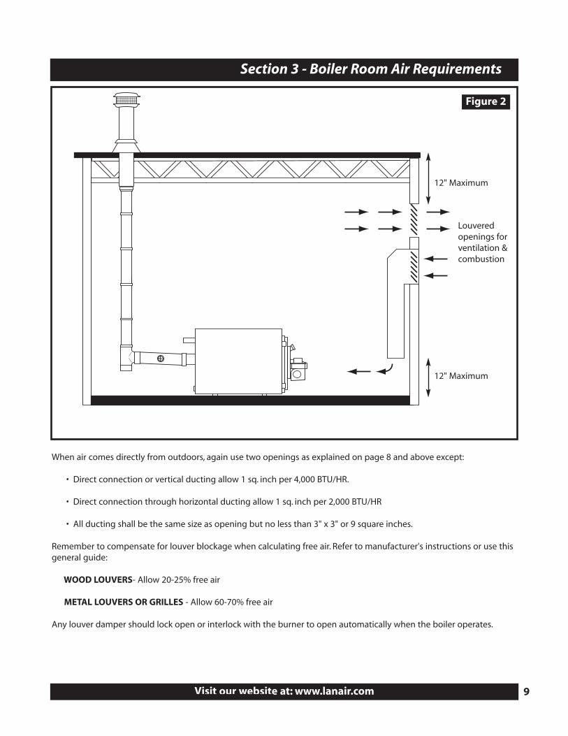
1. To ensure safe efficient operation, the boiler system must be supplied with sufficient air for combustion and ventila-tion (see Fig. 2)
2. Unless properly controlled, avoid the use of forced ventilation, since it can create an undesirable pressure differen-tial between the boiler room and air source.
3. All boilers located in confined rooms should have free access to ventilation and combustion air from two perma-nent openings. One opening should terminate within 12" of the ceiling, the other within 12" from the floor (see Fig. 2). Each opening shall have at least 1 sq. inch free area per 1,000 BTU/HR of burner input. Openings shouldfreely connect with areas having adequate infiltration of outside air
WARNING: Failure to provide an adequate supply of fresh air for combustion will resultin hazardous operating conditions. Do not use an exhaust fan in the boiler room.!
Visit our website at: www.lanair.com 9
Section 3 - Boiler Room Air Requirements
Figure 2
When air comes directly from outdoors, again use two openings as explained on page 8 and above except:
• Direct connection or vertical ducting allow 1 sq. inch per 4,000 BTU/HR.
• Direct connection through horizontal ducting allow 1 sq. inch per 2,000 BTU/HR
• All ducting shall be the same size as opening but no less than 3" x 3" or 9 square inches.
Remember to compensate for louver blockage when calculating free air. Refer to manufacturer's instructions or use thisgeneral guide:
WOOD LOUVERS- Allow 20-25% free air
METAL LOUVERS OR GRILLES - Allow 60-70% free air
Any louver damper should lock open or interlock with the burner to open automatically when the boiler operates.
12" Maximum
Louveredopenings forventilation &combustion
12" Maximum
QUESTIONS?... Contact Customer Service at 1-800-753-1601 M-F 8:00 am- 4:30 pm CST10
Section 4 - Chimney or Vent System
Figure 3
8" Class "A" Chimney
Capped Clean-out Tee
NOTE: Horizontal pipemust have a 1/4" riseper foot of length
NOTE: Chimneyadapter is included.
P/N 4799
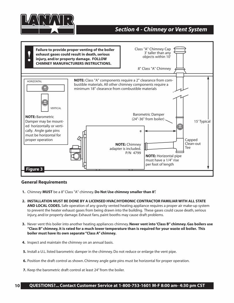
NOTE: Class "A" components require a 2" clearance from com-bustible materials. All other chimney components require aminimum 18" clearance from combustible materials
Class "A" Chimney Cap3' taller than any
objects within 10'
Barometric Damper(24"-36" from boiler)
15' Typical
Failure to provide proper venting of the boilerexhaust gases could result in death, seriousinjury, and/or property damage. FOLLOWCHIMNEY MANUFACTURERS INSTRUCTIONS.
!
General Requirements
1. Chimney MUST be a 8” Class "A" chimney. Do Not Use chimney smaller than 8”.
2. INSTALLATION MUST BE DONE BY A LICENSED HVAC/HYDRONIC CONTRACTOR FAMILIAR WITH ALL STATEAND LOCAL CODES. Safe operation of any gravity vented heating appliance requires a proper air make-up systemto prevent the heater exhaust gases from being drawn into the building. These gases could cause death, seriousinjury, and/or property damage. Exhaust fans, paint booths may cause draft problems.
3. Never vent this boiler into another heating appliances chimney. Never vent into ‘Class B” chimney. Gas boilers use“Class B” chimney, it is rated for a much lower temperature than is required for your waste oil boiler. Thisboiler must have its own separate “Class A” chimney.
4. Inspect and maintain the chimney on an annual basis.
5. Install a U.L. listed barometric damper in the chimney. Do not reduce or enlarge the vent pipe.
6. Position the draft control as shown. Chimney angle gate pins must be horizontal for proper operation.
7. Keep the barometric draft control at least 24” from the boiler.
NOTE: BarometricDamper may be mount-ed horizontally or verti-cally. Angle gate pinsmust be horizontal forproper operation
HORIZONTAL
VERTICAL
8. Do not use more than one 90° elbow. Each 90° elbow equals a 10’ run of chimney. The maximum run for the chimneyconnector is 30’.
9. Secure all connections in the chimney connector with 3 screws per joint.
10. The chimney connector clearance to any combustible material is 18”. The Class "A” chimney clearance to any com-bustible is 2”. FOLLOW THE CHIMNEY MANUFACTURER’S INSTRUCTIONS.
11. Do not install heat re-claimers, manual draft controls, or any other type of restrictive control in the chimney.
12. Install a 8” diameter clean out tee with a cap, at the transition of the chimney.FOLLOW CHIMNEY MANUFACTURER’S INSTRUCTIONS.
13. Use a 8” inside diameter “Class A” insulated chimney pipe to vent exhaust gases through wall, ceilings, attics, roofs,combustibles, etc..
14. Vent chimney at least 3 feet above the roof and at least 3 feet higher than any portion of the building, roof, orobstruction within 10 feet of the chimney.
15. The chimney cap should be at least 3’ above the roof exit.
16. Do not use a rotating chimney cap. Use a non-restrictive “Class A” cap made for the type of “Class A” chimney you areusing. FOLLOW CHIMNEY MANUFACTURER’S INSTRUCTIONS.
17. The chimney must be capable of producing a negative -.02 W.C. draft when cold and -.06 W.C. draft when hot. Referto Section 5 Draft Instructions.
18. If you are unable to attain the proper draft, check for exhaust fans in the building. To test if there is a problem, openan overhead door and see if you now have the proper draft. You may have to add one or more sections of “Class A”chimney to the roof to get the proper draft.
19. The boiler and chimney must be installed in accordance with all state and local codes. The boiler must beinstalled by a licensed HVAC/Hydronics contractor in accordance with the specifications listed in this manual.The chimney must be installed per the chimney manufacturers instruction. Use “Class A” chimney only.
Visit our website at: www.lanair.com 11
Section 4 - Chimney or Vent System
Section 5 - Draft
The boiler should have a (negative) -.02 draft reading when cold, and a (negative) -.06 when hot. Check the boiler when itis running after 45 minutes. If the reading is not what it should be, adjust the barometric damper according to theinstructions provided with the damper. The draft reading should be taken with a manometer. Consult your heating con-tractor, or manometers can be purchased from the Lanair Customer Service Department 800-753-1601.
WARNING: FOLLOW THE CHIMNEY MANUFACTURER’S INSTALLATION INSTRUCTIONS ASWELL AS STATE AND LOCAL FIRE CODES.!
Section 6 - Fuel Supply Tank Installation
QUESTIONS?... Contact Customer Service at 1-800-753-1601 M-F 8:00 am- 4:30 pm CST12
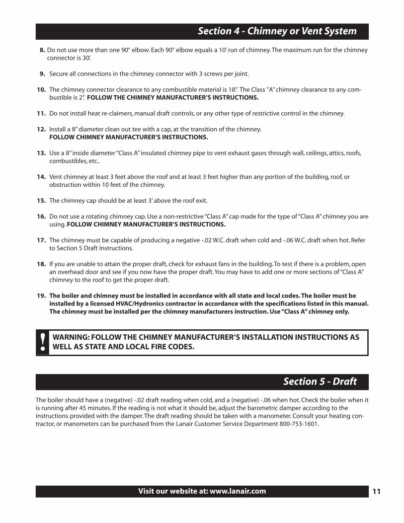
Fuel Regulator Assembly(see page 14)
Vacuum Gauge P/N 83981/2” x 1/4” x 1/4” TeeP/N 9412
Primary StrainerP/N 9807
PUMPASSEMBLY
Check Valve P/N 8662(inside tank)
Strainer Suction Line P/N 8748
PUMPASSEMBLY
TOP VIEW
3/8” Copper Tube P/N 9182
3/8” Fuel Line To Burner (not included)
STORAGETANK
STORAGETANK
1/2” pick-up tube(not included)
3/8” Fuel Line To Burner (not included)
6“ from bottom of tank
Vent
Fill
1“ x 1/2” bushing P/N 8904
1“ x 1/2” bushing P/N 8904
1/4” Nipple P/N 86471/4” x 1/2” Coupling P/N 8558
Figure 4
Visit our website at: www.lanair.com 13
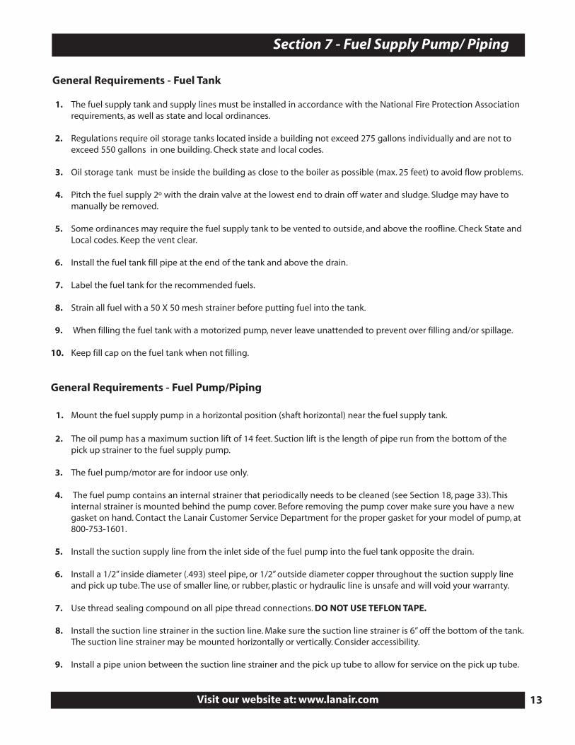
Section 7 - Fuel Supply Pump/ Piping
General Requirements - Fuel Tank
1. The fuel supply tank and supply lines must be installed in accordance with the National Fire Protection Associationrequirements, as well as state and local ordinances.
2. Regulations require oil storage tanks located inside a building not exceed 275 gallons individually and are not toexceed 550 gallons in one building. Check state and local codes.
3. Oil storage tank must be inside the building as close to the boiler as possible (max. 25 feet) to avoid flow problems.
4. Pitch the fuel supply 2º with the drain valve at the lowest end to drain off water and sludge. Sludge may have tomanually be removed.
5. Some ordinances may require the fuel supply tank to be vented to outside, and above the roofline. Check State andLocal codes. Keep the vent clear.
6. Install the fuel tank fill pipe at the end of the tank and above the drain.
7. Label the fuel tank for the recommended fuels.
8. Strain all fuel with a 50 X 50 mesh strainer before putting fuel into the tank.
9. When filling the fuel tank with a motorized pump, never leave unattended to prevent over filling and/or spillage.
10. Keep fill cap on the fuel tank when not filling.
General Requirements - Fuel Pump/Piping
1. Mount the fuel supply pump in a horizontal position (shaft horizontal) near the fuel supply tank.
2. The oil pump has a maximum suction lift of 14 feet. Suction lift is the length of pipe run from the bottom of thepick up strainer to the fuel supply pump.
3. The fuel pump/motor are for indoor use only.
4. The fuel pump contains an internal strainer that periodically needs to be cleaned (see Section 18, page 33). Thisinternal strainer is mounted behind the pump cover. Before removing the pump cover make sure you have a newgasket on hand. Contact the Lanair Customer Service Department for the proper gasket for your model of pump, at800-753-1601.
5. Install the suction supply line from the inlet side of the fuel pump into the fuel tank opposite the drain.
6. Install a 1/2” inside diameter (.493) steel pipe, or 1/2” outside diameter copper throughout the suction supply lineand pick up tube. The use of smaller line, or rubber, plastic or hydraulic line is unsafe and will void your warranty.
7. Use thread sealing compound on all pipe thread connections. DO NOT USE TEFLON TAPE.
8. Install the suction line strainer in the suction line. Make sure the suction line strainer is 6” off the bottom of the tank.The suction line strainer may be mounted horizontally or vertically. Consider accessibility.
9. Install a pipe union between the suction line strainer and the pick up tube to allow for service on the pick up tube.
Section 7 - Fuel Supply Pump/ Piping
QUESTIONS?... Contact Customer Service at 1-800-753-1601 M-F 8:00 am- 4:30 pm CST14
10. Install the check valve (arrow facing towards the pump) on the bottom of the pick up tube.
11. Install a vacuum gauge (included, P/N 8398) in the suction line. This gauge will indicate when service is needed onthe strainer, pump, connections, or fuel level.
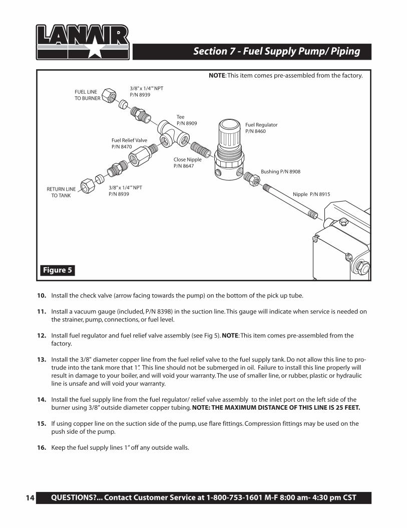
12. Install fuel regulator and fuel relief valve assembly (see Fig 5). NOTE: This item comes pre-assembled from the factory.
13. Install the 3/8" diameter copper line from the fuel relief valve to the fuel supply tank. Do not allow this line to pro-trude into the tank more that 1”. This line should not be submerged in oil. Failure to install this line properly willresult in damage to your boiler, and will void your warranty. The use of smaller line, or rubber, plastic or hydraulicline is unsafe and will void your warranty.
14. Install the fuel supply line from the fuel regulator/ relief valve assembly to the inlet port on the left side of theburner using 3/8” outside diameter copper tubing. NOTE: THE MAXIMUM DISTANCE OF THIS LINE IS 25 FEET.
15. If using copper line on the suction side of the pump, use flare fittings. Compression fittings may be used on thepush side of the pump.
16. Keep the fuel supply lines 1” off any outside walls.
Fuel Relief ValveP/N 8470
Fuel RegulatorP/N 8460
Bushing P/N 8908
Nipple P/N 8915
TeeP/N 8909
Close NippleP/N 8647
3/8” x 1/4’” NPTP/N 8939
3/8” x 1/4’” NPTP/N 8939
FUEL LINETO BURNER
RETURN LINETO TANK
Figure 5
NOTE: This item comes pre-assembled from the factory.

System Return
CheckValve
BlendPump
System Supply
Pressure Reduction Valve
Backflow Preventer
System Circulator
Amtrol #720Air Eliminator
or Equal
From City Water Supply
ExpansionTank
Air Separator
*
Figure 6
ATTENTION: Heating system design and burner oper-ation must incorporate interlock to prevent burnerfrom firing when boiler has no system water flow.!
*16.3 GPM Blend Pump should be used
Visit our website at: www.lanair.com 15
Section 8 - Typical Boiler Piping
System Supply
System Return
Pressure Reduction Valve
Backflow Preventer
System Circulator
Amtrol #720Air Eliminator
or Equal
From City Water Supply
ExpansionTank
Air Separator
CheckValve
BlendPump
CheckValve
BlendPump
12” Max.
12” Max.
NOTES:• Size secondary Pump GPM at gross boiler output
for a 20” drop.
• When calculating pump head, the maximum boiler resistance for any boiler will not exceed 14” in W.C. of head
Single Boiler Piping with Blend Pump
Figure 6B Single or Multiple Boiler Piping for Primary/Secondary Pumping
QUESTIONS?... Contact Customer Service at 1-800-753-1601 M-F 8:00 am- 4:30 pm CST16
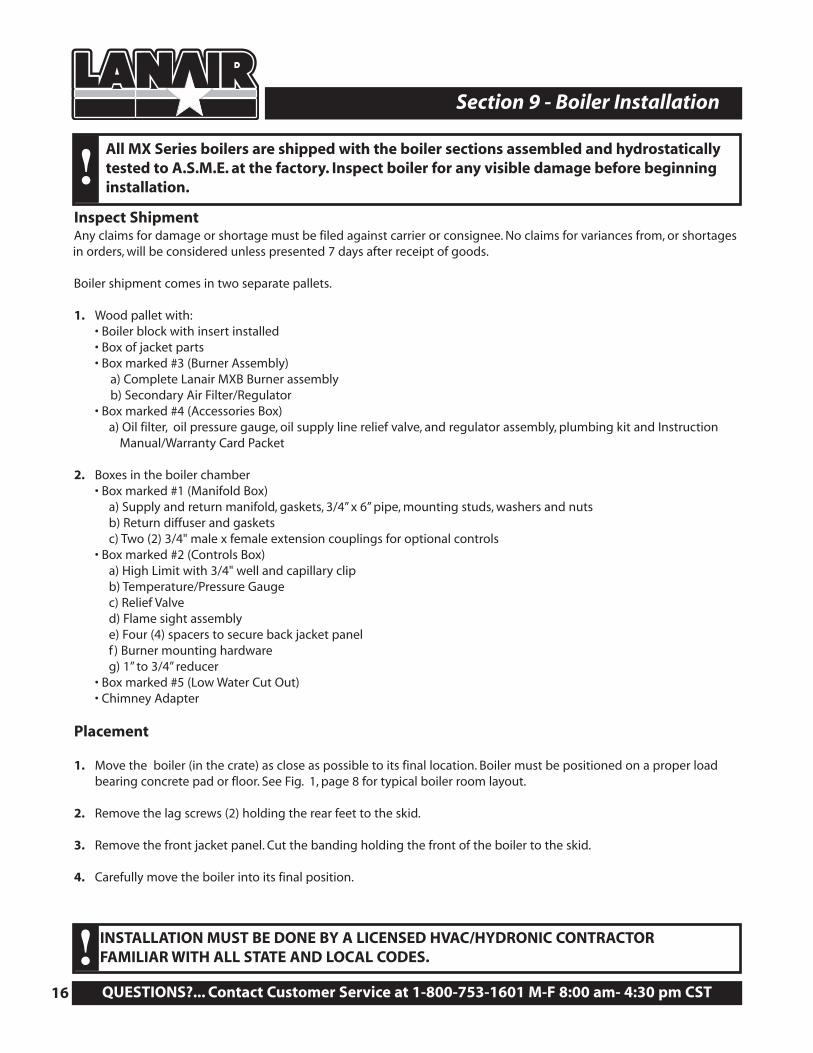
Section 9 - Boiler Installation
Inspect ShipmentAny claims for damage or shortage must be filed against carrier or consignee. No claims for variances from, or shortagesin orders, will be considered unless presented 7 days after receipt of goods.
Boiler shipment comes in two separate pallets.
1. Wood pallet with:• Boiler block with insert installed• Box of jacket parts• Box marked #3 (Burner Assembly)
a) Complete Lanair MXB Burner assemblyb) Secondary Air Filter/Regulator
• Box marked #4 (Accessories Box)a) Oil filter, oil pressure gauge, oil supply line relief valve, and regulator assembly, plumbing kit and Instruction
Manual/Warranty Card Packet
2. Boxes in the boiler chamber• Box marked #1 (Manifold Box)
a) Supply and return manifold, gaskets, 3/4” x 6” pipe, mounting studs, washers and nutsb) Return diffuser and gasketsc) Two (2) 3/4" male x female extension couplings for optional controls
• Box marked #2 (Controls Box)a) High Limit with 3/4" well and capillary clipb) Temperature/Pressure Gaugec) Relief Valved) Flame sight assemblye) Four (4) spacers to secure back jacket panelf ) Burner mounting hardwareg) 1” to 3/4” reducer
• Box marked #5 (Low Water Cut Out)• Chimney Adapter
Placement
1. Move the boiler (in the crate) as close as possible to its final location. Boiler must be positioned on a proper loadbearing concrete pad or floor. See Fig. 1, page 8 for typical boiler room layout.
2. Remove the lag screws (2) holding the rear feet to the skid.
3. Remove the front jacket panel. Cut the banding holding the front of the boiler to the skid.
4. Carefully move the boiler into its final position.
All MX Series boilers are shipped with the boiler sections assembled and hydrostaticallytested to A.S.M.E. at the factory. Inspect boiler for any visible damage before beginninginstallation.!
INSTALLATION MUST BE DONE BY A LICENSED HVAC/HYDRONIC CONTRACTOR FAMILIAR WITH ALL STATE AND LOCAL CODES.!
Visit our website at: www.lanair.com 17
Section 9 - Boiler Installation
Figure 7
Figure 8
(4) 12mm x 50mm studs
(4) 12mm x 50mm studs
(4) 12mm washers
(4) 12mm washers
(4) 12mm nut
(4) 12mm nut
Supply Manifold
Return Flange
Gasket
Gasket
Gasket
Diffuser
TOP OF BOILER
BOTTOM OF BOILER
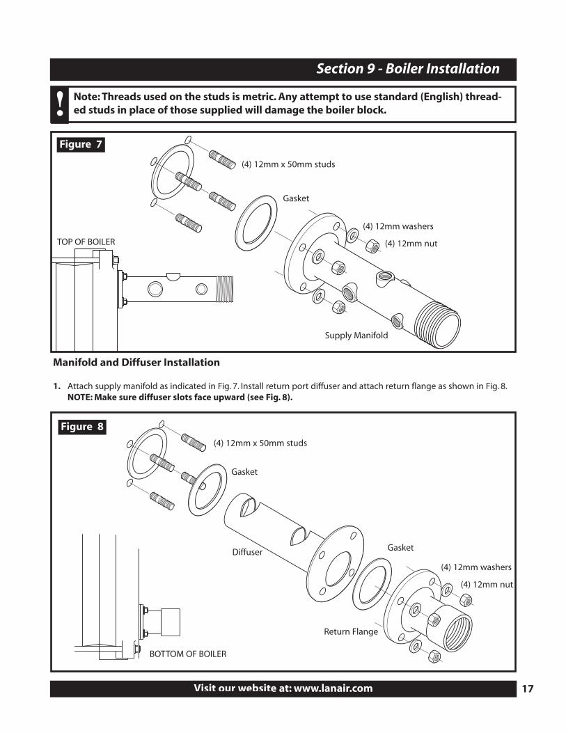
Note: Threads used on the studs is metric. Any attempt to use standard (English) thread-ed studs in place of those supplied will damage the boiler block.!
Manifold and Diffuser Installation
1. Attach supply manifold as indicated in Fig. 7. Install return port diffuser and attach return flange as shown in Fig. 8.NOTE: Make sure diffuser slots face upward (see Fig. 8).
QUESTIONS?... Contact Customer Service at 1-800-753-1601 M-F 8:00 am- 4:30 pm CST18
Section 9 - Boiler Installation
Figure 9
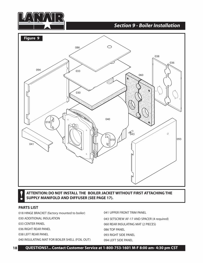
ATTENTION: DO NOT INSTALL THE BOILER JACKET WITHOUT FIRST ATTACHING THESUPPLY MANIFOLD AND DIFFUSER (SEE PAGE 17).!
PARTS LIST018 HINGE BRACKET (factory mounted to boiler)
030 ADDITIONAL INSULATION
033 CENTER PANEL
036 RIGHT REAR PANEL
038 LEFT REAR PANEL
040 INSULATING MAT FOR BOILER SHELL (FOIL OUT)
041 UPPER FRONT TRIM PANEL
043 SETSCREW AF-17 AND SPACER (4 required)
060 REAR INSULATING MAT (2 PIECES)
086 TOP PANEL
093 RIGHT SIDE PANEL
094 LEFT SIDE PANEL
094
086
060
038
036
093
043
040
018
018
041
033
030
Visit our website at: www.lanair.com 19
Section 9 - Boiler Installation
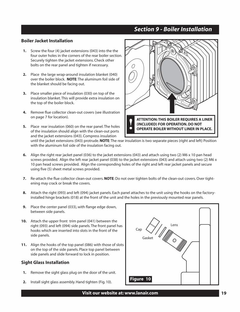
Boiler Jacket Installation
1. Screw the four (4) jacket extensions (043) into the thefour outer holes in the corners of the rear boiler section.Securely tighten the jacket extensions. Check otherbolts on the rear panel and tighten if necessary.
2. Place the large wrap-around insulation blanket (040)over the boiler block. NOTE: The aluminum foil side ofthe blanket should be facing out.
3. Place smaller piece of insulation (030) on top of theinsulation blanket. This will provide extra insulation onthe top of the boiler block.
4. Remove flue collector clean-out covers (see illustrationon page 7 for location).
5. Place rear insulation (060) on the rear panel. The holesof the insulation should align with the clean-out portsand the jacket extensions (043). Compress insulationuntil the jacket extensions (043) protrude. NOTE: The rear insulation is two separate pieces (right and left) Positionwith the aluminum foil side of the insulation facing out.
6. Align the right rear jacket panel (036) to the jacket extensions (043) and attach using two (2) M6 x 10 pan headscrews provided. Align the left rear jacket panel (038) to the jacket extensions (043) and attach using two (2) M6 x10 pan head screws provided. Align the corresponding holes of the right and left rear jacket panels and secureusing five (5) sheet metal screws provided.
7. Re-attach the flue collector clean-out covers. NOTE: Do not over tighten bolts of the clean-out covers. Over tight-ening may crack or break the covers.
8. Attach the right (093) and left (094) jacket panels. Each panel attaches to the unit using the hooks on the factory-installed hinge brackets (018) at the front of the unit and the holes in the previously mounted rear panels.
9. Place the center panel (033), with flange edge down,between side panels.
10. Attach the upper front trim panel (041) between theright (093) and left (094) side panels. The front panel hashooks which are inserted into slots in the front of theside panels.
11. Align the hooks of the top panel (086) with those of slotson the top of the side panels. Place top panel betweenside panels and slide forward to lock in position.
Cap
Gasket
Lens
Sight Glass Installation
1. Remove the sight glass plug on the door of the unit.
2. Install sight glass assembly. Hand tighten (Fig. 10).Figure 10
ATTENTION: THIS BOILER REQUIRES A LINER(INCLUDED) FOR OPERATION. DO NOTOPERATE BOILER WITHOUT LINER IN PLACE.!
QUESTIONS?... Contact Customer Service at 1-800-753-1601 M-F 8:00 am- 4:30 pm CST20
Section 10 - Boiler Controls and Accessory Location
Burner Service Switch
MX BOILER
Figure 11
Figure 12Boiler Controls and Accessory Location
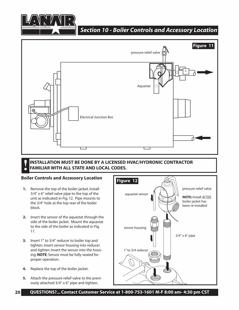
1. Remove the top of the boiler jacket. Install3/4" x 6" relief valve pipe to the top of theunit as indicated in Fig. 12. Pipe mounts tothe 3/4" hole at the top rear of the boilerblock.
2. Insert the sensor of the aquastat through theside of the boiler jacket. Mount the aquastatto the side of the boiler as indicated in Fig.11.
3. Insert 1" to 3/4" reducer to boiler top andtighten. Insert sensor housing into reducerand tighten. Insert the sensor into the hous-ing. NOTE: Sensor must be fully seated forproper operation.
4. Replace the top of the boiler jacket.
5. Attach the pressure relief valve to the previ-ously attached 3/4" x 6" pipe and tighten.
pressure relief valve
NOTE: Install AFTERboiler jacket hasbeen re-installed
aquastat sensor
sensor housing
1” to 3/4 reducer
3/4" x 6" pipe
Aquastat
pressure relief valve
Electrical Junction Box
INSTALLATION MUST BE DONE BY A LICENSED HVAC/HYDRONIC CONTRACTOR FAMILIAR WITH ALL STATE AND LOCAL CODES.!
Visit our website at: www.lanair.com 21
Section 10 - Boiler Controls and Accessory Location
Section 11 - Burner Installation
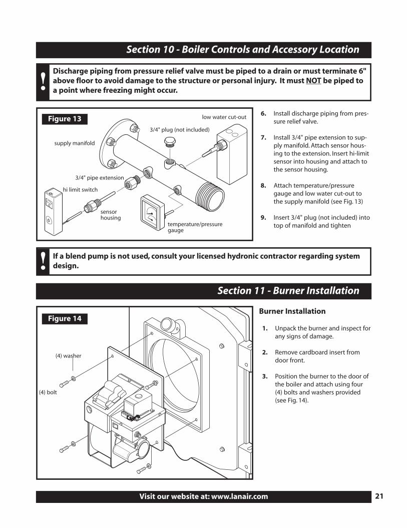
6. Install discharge piping from pres-sure relief valve.
7. Install 3/4" pipe extension to sup-ply manifold. Attach sensor hous-ing to the extension. Insert hi-limitsensor into housing and attach tothe sensor housing.
8. Attach temperature/pressuregauge and low water cut-out tothe supply manifold (see Fig. 13)
9. Insert 3/4" plug (not included) intotop of manifold and tighten
Burner Installation
1. Unpack the burner and inspect forany signs of damage.
2. Remove cardboard insert fromdoor front.
3. Position the burner to the door ofthe boiler and attach using four(4) bolts and washers provided(see Fig. 14).
Discharge piping from pressure relief valve must be piped to a drain or must terminate 6"above floor to avoid damage to the structure or personal injury. It must NOT be piped toa point where freezing might occur.!
If a blend pump is not used, consult your licensed hydronic contractor regarding systemdesign.!
Figure 13
hi limit switch
temperature/pressuregauge
low water cut-out
3/4" plug (not included)
supply manifold
3/4" pipe extension
sensorhousing
Figure 14
(4) bolt
(4) washer
QUESTIONS?... Contact Customer Service at 1-800-753-1601 M-F 8:00 am- 4:30 pm CST22
Section 12 - Electrical Connections
Main Electrical Installation
1. All wiring must comply with the National Electrical Code. State and Local Ordinances, and be wired by a qualifiedelectrician.
2. Electrical service MUST be connected to a separate 20 AMP, 115 VAC, 60 HZ single phase circuit.
3. Electrical service connections are made in the electrical junction box on side of the boiler.
4. The boiler must have a safety equipment ground from the main electrical service, stranded 12 GA minimum.
5. The electrical conductors for electrical service to the heater MUST be stranded 12 GA minimum.
6. Install a manual service disconnect near the heater, and label its function.
7. The supply voltage must be maintained at a minimum 110 VAC.
8. The electrical conductors from the main electrical service must be within approved conduit.
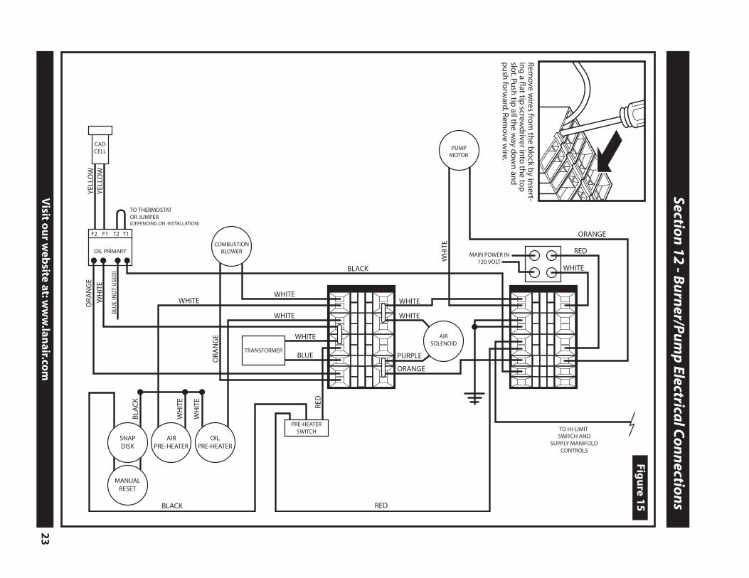
9. Keep all electrical conductors and conduit away from the chimney connector as well as any other hot surfaces. Referto Figure 15, Wiring Diagram for color code, etc. Keep the power off until the heater is ready to be started. Refer toSection 13 Start Up Procedure.
Fuel Supply Pump Electrical Installation1. All wiring must comply with the National Electrical Code, State and Local Ordinances, and be wired by a qualified
electrician.
2. The electrical conductors to the fuel pump motor MUST be stranded 14 GA minimum.
3. The electrical service connections for the fuel pump motor are made in the electrical junction box on the side of theboiler.
4. The pump motor MUST have a safety equipment ground from the main electrical service, stranded 12 GA minimum.
5. The electrical conductors from the electrical junction box to the pump motor must be within approved conduit.
6. Keep all electrical conductors and conduit away from the chimney connector as well as any other hot surfaces. Referto Figure 15 Wiring Diagram for color code, etc. Keep the power off until the boiler is ready to be started. Refer toSection 13 Start Up Procedure.
Hi-Limit Switch and Manifold Controls Electrical Installation
All wiring must comply with the National Electrical Code. State and Local Ordinances, and be wired by a qualifiedelectrician.
CAUTION: HAZARD OF ELECTRICAL SHOCK!!
ATTENTION! DUE TO VARYING SYSTEM DESIGNS, ONLY A CERTIFIED HVAC/HYDRONICSINSTALLER CAN DETERMINE THE PROPER WIRING OF THESE COMPONENTS.!
Visit o
ur w
ebsite at:w
ww
.lanair.co
m
23
Section
12 - Bu
rner/P
um
p Electrica
l Co
nn
ection
s
CADCELL
YEL
LOW
YEL
LOW
WHITE
BLUE
ORA
NG
E
WHITE
WHITE
PURPLE
WHITE
ORANGE
RED
WHITE
WHITE
BLA
CK
WH
ITE
WH
ITE
SNAPDISK
TRANSFORMER
COMBUSTIONBLOWER
PRE-HEATERSWITCH
AIRSOLENOID
OIL PRIMARY
F2 F1 T2 T1
AIRPRE-HEATER
OILPRE-HEATER
WH
ITE
ORA
NG
E
BLACK
BLACK
PUMPMOTOR
WHITE
RED
ORANGE
RED
WH
ITE
MANUALRESET
BLU
E (N
OT
USE
D)
MAIN POWER IN120 VOLT
TO HI-LIMIT SWITCH AND
SUPPLY MANIFOLDCONTROLS
TO THERMOSTAT OR JUMPER(DEPENDING ON INSTALLATION)
Figu
re 15
Remove w
ires from
the b
lock b
y insert-
ing
a flat tip screw
driver in
to th
e top
slot.Pu
sh tip
all the w
ay do
wn
and
pu
sh fo
rward
.Remove w
ire.
QUESTIONS?... Contact Customer Service at 1-800-753-1601 M-F 8:00 am- 4:30 pm CST24
Section 13 - Compressed Air Installation
Compressed Air Supply Installation
1. Install an air pressure supply line connection to the air filter/regulator.
2. The air supply source must be capable of producing 1.0 CFM @ 100 PSI.
3. Install a shut off valve in the air supply line for service.
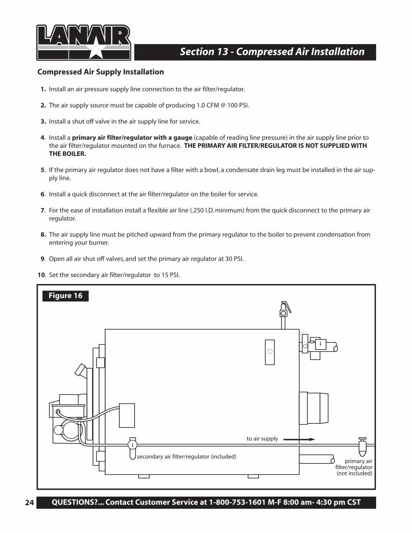
4. Install a primary air filter/regulator with a gauge (capable of reading line pressure) in the air supply line prior tothe air filter/regulator mounted on the furnace. THE PRIMARY AIR FILTER/REGULATOR IS NOT SUPPLIED WITHTHE BOILER.
5. If the primary air regulator does not have a filter with a bowl, a condensate drain leg must be installed in the air sup-ply line.
6. Install a quick disconnect at the air filter/regulator on the boiler for service.
7. For the ease of installation install a flexible air line (.250 I.D. minimum) from the quick disconnect to the primary airregulator.
8. The air supply line must be pitched upward from the primary regulator to the boiler to prevent condensation fromentering your burner.
9. Open all air shut off valves, and set the primary air regulator at 30 PSI.
10. Set the secondary air filter/regulator to 15 PSI.
Figure 16
secondary air filter/regulator (included)primary air
filter/regulator(not included)
to air supply
Visit our website at: www.lanair.com 25
Section 14 - Controls
Burner Controls and Operation
• Oil Primary Safety Control/Cad Cell:The oil primary control is mounted on top of the burner’s electrical box. When the thermostat calls for heat the oilprimary control starts the burner by switching on the air solenoid valve, ignition transformer, combustion air blower,and the fuel pump. The oil primary control works in conjunction with the cadmium sulfide cell (cad cell). The cad cellis mounted inside the burner cover, and faces the flame. The cad cell monitors the light level inside the combustionchamber to insure there is a flame present. If there is a loss of flame the primary control will go into its recyclemode. After 1-2 minutes the primary control will restart the burner. When this happens if there is a flame present,the burner will continue to function. If on start up no flame is established in 30 seconds the primary control will lockout. CAUTION: Do not press the reset button more than twice. If the burner fails to start refer to Section 19, TroubleShooting.
• Barometric Draft Control:The Barometric Draft Control automatically maintains a pre-set chimney draft, and is located in the chimney connec-tor (see page 10, Fig. 3). NOTE: The draft must be set/checked using a manometer.
• Air Filter/Regulator:The Air Filter/Regulator performs two functions: 1. It removes condensation and dirt from the air. 2. It controls theamount of air pressure reaching the nozzle and air operated fuel valve. The Air/Filter Regulator is mounted on thecabinet near the burner.
• Electric Air Solenoid Valve:The Electric Air Solenoid Valve is controlled by the Oil Primary Control. It acts as a shut-off valve, (it’s open duringoperation, and closed when the burner is off ). The Electric Air Solenoid Valve is located inside of the burner’s electri-cal box.
• Air Operated Fuel Valve:The Air Operated Fuel Valve controls fuel flow to the nozzle. When the Electric Air Solenoid Valve opens and air pres-sure pushes on the fuel valve diaphragm, the plunger moves off the nozzle seat allowing fuel to enter the nozzle.The Air Operated Fuel Valve is located on the back of the air pre-heater.
• Air/Oil Pre-heater:The Air/Oil pre-heater is an assembly that preheats the atomizing air and fuel to a predetermined temperature toproperly combust used oil. The Air/Oil pre-heater is located in the burner.
• Snap Disc Assembly:The Snap Disc accurately controls the temperature of the air/oil pre-heater assembly with two resistance type car-tridge-heating elements. The Snap Disc is mounted on the oil pre-heater inside the burner.
• Nozzle:The Nozzle uses air pressure to help pull fuel through its small orifice, and to atomize the fuel for proper combus-tion. The Nozzle is located on the end of the air pre-heater opposite the fuel valve. Replace the Nozzle annually, asthey are prone to wear by contaminants in waste oil/used oil.
Fuel Pump Controls and Operation
• Fuel Supply Pump:The Fuel Supply Pump pumps fuel from your oil storage tank to the burner. The Fuel Supply Pump should be locat-ed as close to the fuel supply tank as possible. The Fuel Supply Pump must be mounted horizontally (Shaft). Seepage 12, Fig. 4.
QUESTIONS?... Contact Customer Service at 1-800-753-1601 M-F 8:00 am- 4:30 pm CST26
Section 14 - Controls
Fuel Pump Controls and Operation
• Fuel Regulator:A Fuel regulator is used to adjust the fuel pressure of waste oil to the burner.
• Fuel Relief Valve:The fuel relief valve prevents excess pressure build-up in the fuel line upon burner shut-down.
Boiler Controls and Operation
• Hi-Limit Switch:Hi-limit switches are immersion type devices for regulating the temperature of liquids in a boiler where temperaturecontrol is required. The Hi-limit switch is mounted to the supply manifold at the rear of the boiler (see page 21 fordetails).
• Low Water Cut-Out:The low water cut-out switch is located on the supply manifold at the rear of the boiler. This device will turn the sys-tem off if it senses low water levels or pressure. The low water cut-out switch is mounted to the manifold at the rearof the boiler (see page 21 for details).
• Aquastat The aquastat is an immersion type device for limiting the temperature of liquids in a boiler. The aquastat is mountedto the cabinet and the sensor is installed at the rear of the boiler next to the pressure relief valve (see page 20)
• Pressure Relief Valve:The Pressure Relief Valve is mounted to the top of the boiler near the rear. This valve is used to automatically ormanually release excess pressure which may be present in the boiler. See page 20.
• Temperature/Pressure Gauge:This dual purpose gauge monitors supply temperature and pressure. The temperature/pressure gauge is mountedto the supply manifold at the rear of the boiler (see page 21).
Section 15 - Start-Up Procedures
Boiler Start-Up - Fill System
1. Fill boiler and system according to job specifications. System pressure should be set to have 5 PSI pressure at thehighest point in the heating system. Boiler pressure gauge will indicate pressure relative to the height of water col-umn from the boiler to the highest point, plus the additional 5 PSI.
Example: To calculate cold fill pressure: Highest point in system is 40’; 40 ÷ 2.31 = 17.32 (1 PSI = 2.31 ft w.c.)Add 5 PSI to 17.32 = 22.32 PSI; boiler pressure gauge will indicate 22.32 PSI (cold fill pressure)
2. Purge air from boiler and system . WARNING: Never purge system while boiler is in operation or fill a hot/emptyboiler with cold water
The expansion tank must be properly sized to system requirements. An undersized expansion tank willcause system water to be lost through the relief valve and make-up water to be introduced through the fillvalve eventually causing mineral build-up in the boiler sections which could lead to eventual section failure.!
Visit our website at: www.lanair.com 27
Section 15 - Start-Up Procedures
Waste Oil Burner Start-Up
1. Make sure the main electrical service for the heater is turned off, and locked out.
2. Fill the oil supply tank with an approved fuel to a level that is above the pick-up tube check valve.
3. Check for proper draft in the chimney. The draft must read -.02 W.C. cold.
4. Make sure there is air pressure at the heaters air filter/regulator, set it at 12 PSI. Set the primary regulator on the airsupply line to 30 PSI.
5. Set the fan/limit control slide switch to automatic.
6. Check the combustion air adjustment baffle for proper setting. Refer to Section 17, Flame Adjustment.
7. Set the room thermostat below room temperature (if applicable).
8. Turn the main electrical service ON.
9. Push the reset button on the oil primary control for 3 seconds.
10. Flip the lighted rocker switch for preheating on the burner electrical box to the ON position (pre-heater OFF thelight is off, pre-heater ON the light is on.).
11. Prime the fuel supply pump. Refer to Section 16, Priming the Fuel Supply Pump.
12. If using waste10W-50W oil or automatic transmission fluid for fuel, flip the pre-heater rocker switch on (light ON, andwait 5-7 minutes for the pre-heater assembly to reach operating temperature. Leave the pre-heater switch OFF ifusing No. 1 or No. 2 fuel oil.
13. Turn the room thermostat up above the room temperature (if applicable). The burner will now fire, check the sightglass on the rear of the burner also inspect the flame through the inspection port. Refer to section 17, FlameAdjustment pages 29-30.
14. Adjust the burner air filter/regulator to 12 PSI, and the primary air regulator to 30 PSI. NOTE: 12 PSI on the airfilter/regulator is the starting point, you may need to adjust from there when setting the flame. See pages 29-30.
15. Adjust the fuel pressure gauge on the left side of the burner to read 7lbs.. NOTE: Adjust the knob on the fuel regula-tor clockwise to increase pressure, and counter clockwise to decrease pressure to the burner. The oil pressures listedabove are a starting point, you may need to adjust from there when setting the flame. Refer to section 17, FlameAdjustment pages 29-30.
16. Adjust the barometric damper to obtain a draft of -.06 W.C. while the heater is hot and operating. NOTE: It is VERYIMPORTANT that the barometric damper is set to the required settings to ensure the natural draft of exhaust gases.See Section 5, Draft , page 11.
17. Depending on the type of fuel used, the elevation, temperature, and oil viscosity, the combustion air baffle will needto be adjusted for optimum performance. Refer to section 17, Flame Adjustment pages 29-30.
The combustion air baffle is NOT factory set!
QUESTIONS?... Contact Customer Service at 1-800-753-1601 M-F 8:00 am- 4:30 pm CST28
Section 16 - Priming the Fuel Pump
1. The fuel level in the supply tank must be above the check valveon the pick-up tube. Fill suction line with oil.
2. Remove the bowl of the suction line strainer, and fill with cleanfuel. Replace the strainer bowl.
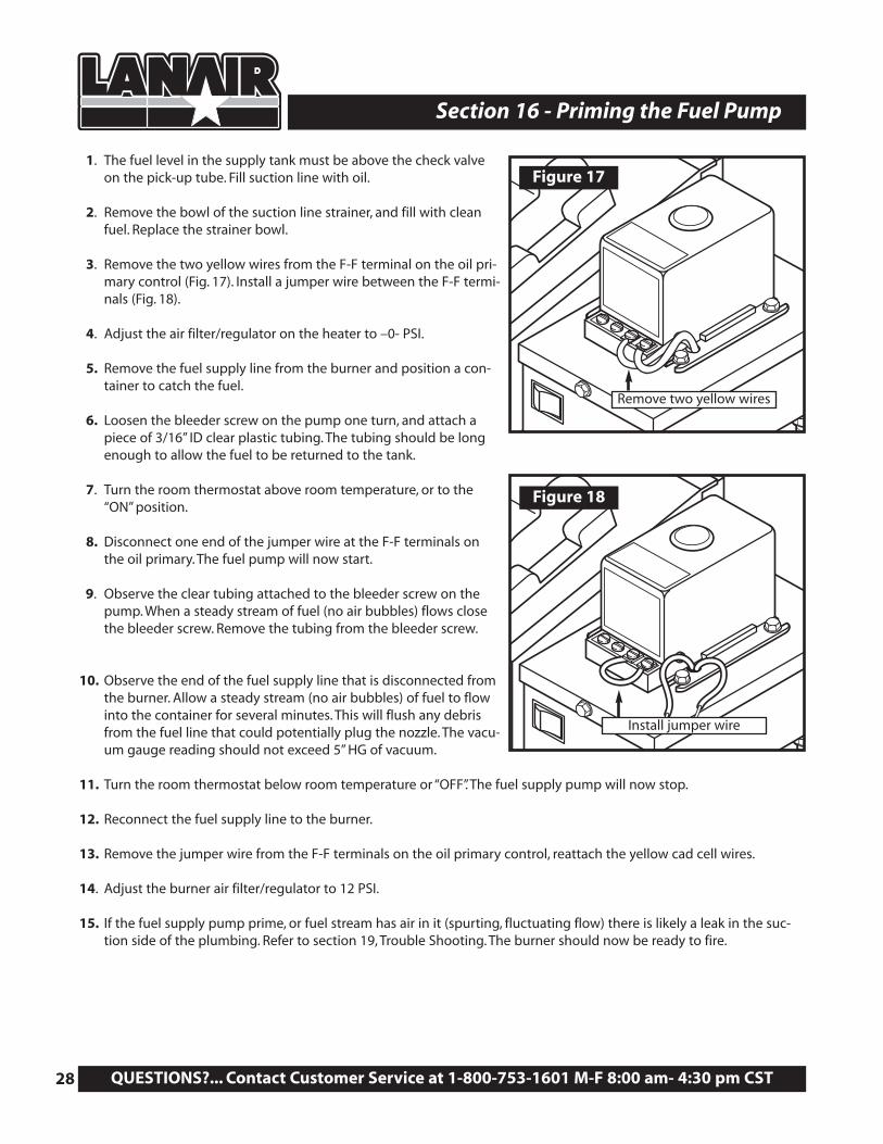
3. Remove the two yellow wires from the F-F terminal on the oil pri-mary control (Fig. 17). Install a jumper wire between the F-F termi-nals (Fig. 18).
4. Adjust the air filter/regulator on the heater to –0- PSI.
5. Remove the fuel supply line from the burner and position a con-tainer to catch the fuel.
6. Loosen the bleeder screw on the pump one turn, and attach apiece of 3/16” ID clear plastic tubing. The tubing should be longenough to allow the fuel to be returned to the tank.
7. Turn the room thermostat above room temperature, or to the“ON” position.
8. Disconnect one end of the jumper wire at the F-F terminals onthe oil primary. The fuel pump will now start.
9. Observe the clear tubing attached to the bleeder screw on thepump. When a steady stream of fuel (no air bubbles) flows closethe bleeder screw. Remove the tubing from the bleeder screw.
10. Observe the end of the fuel supply line that is disconnected fromthe burner. Allow a steady stream (no air bubbles) of fuel to flowinto the container for several minutes. This will flush any debrisfrom the fuel line that could potentially plug the nozzle. The vacu-um gauge reading should not exceed 5” HG of vacuum.
11. Turn the room thermostat below room temperature or “OFF”. The fuel supply pump will now stop.
12. Reconnect the fuel supply line to the burner.
13. Remove the jumper wire from the F-F terminals on the oil primary control, reattach the yellow cad cell wires.
14. Adjust the burner air filter/regulator to 12 PSI.
15. If the fuel supply pump prime, or fuel stream has air in it (spurting, fluctuating flow) there is likely a leak in the suc-tion side of the plumbing. Refer to section 19, Trouble Shooting. The burner should now be ready to fire.
Figure 17
Figure 18
Remove two yellow wires
Install jumper wire
Visit our website at: www.lanair.com 29
Section 17 - Flame Adjustment
Flame Adjustment
1. Start boiler, let it run for at least 45 minutes to reach operating temperature before proceeding.
2. Check chimney draft, set the barometric damper to -.06 WC when hot and running.
3. Check the atomizing air pressure, set the air filter/regulator on the heater to 15 PSI as a starting point.
4. Check the fuel pressure gauge on the burner, set to: 7 LBS.
Adjust the screw on the fuel regulator. Lock into position. The flame should extend no more than 3/4 of the way intothe chamber.
NOTE: The above pressure is a starting point, depending on your installation you may need further adjustment.
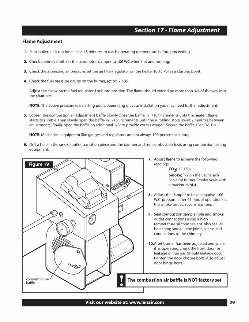
5. Loosen the combustion air adjustment baffle, slowly close the baffle in 1/16” increments until the heater (flame)starts to rumble. Then slowly open the baffle in 1/16” increments until the rumbling stops, (wait 2 minutes betweenadjustments) finally open the baffle an additional 1/8” to provide excess oxygen. Secure the baffle, (See Fig 19).
NOTE: Mechanical equipment like gauges and regulators are not always 100 percent accurate,
6. Drill a hole in the smoke outlet transition piece and the damper and run combustion tests using combustion testingequipment.
7. Adjust flame to achieve the following readings:
CO2; 12-15%
Smoke; 1-2 on the Bacharach Scale Oil Burner Smoke Scale with a maximum of 4.
8. Adjust the damper to have negative -.06 W.C. pressure (after 45 min. of operation) atthe smoke outlet. Secure damper.
9. Seal combustion sample hole and smoke outlet connections using a high temperature silicone sealant. Also seal all breeching smoke pipe joints, seams and connections to the chimney.
10.After burner has been adjusted and while it is operating, check the front door for leakage of flue gas. Should leakage occur,tighten the door closure bolts. Also adjust door hinge bolts.
Figure 19
combustion airbaffle
The combustion air baffle is NOT factory set!
QUESTIONS?... Contact Customer Service at 1-800-753-1601 M-F 8:00 am- 4:30 pm CST30
Section 17 - Flame Adjustment
Flame Adjustment - Visual
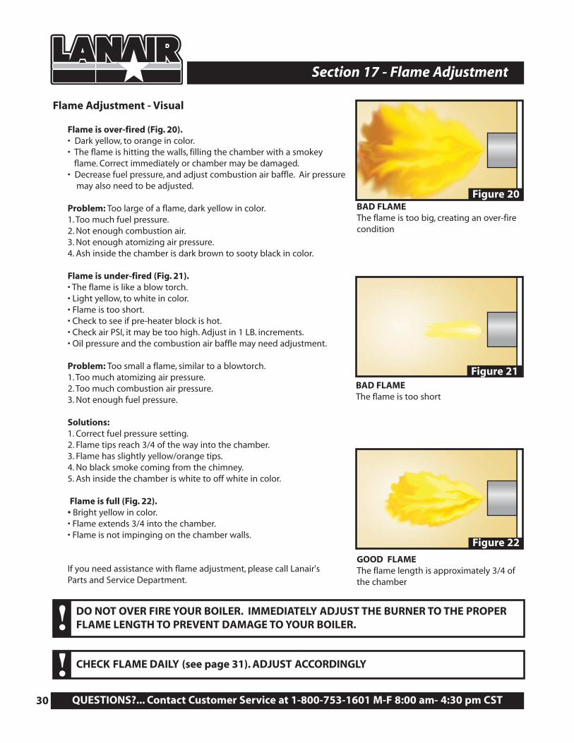
Flame is over-fired (Fig. 20).• Dark yellow, to orange in color.• The flame is hitting the walls, filling the chamber with a smokey
flame. Correct immediately or chamber may be damaged.• Decrease fuel pressure, and adjust combustion air baffle. Air pressure
may also need to be adjusted.
Problem: Too large of a flame, dark yellow in color.1. Too much fuel pressure.2. Not enough combustion air.3. Not enough atomizing air pressure.4. Ash inside the chamber is dark brown to sooty black in color.
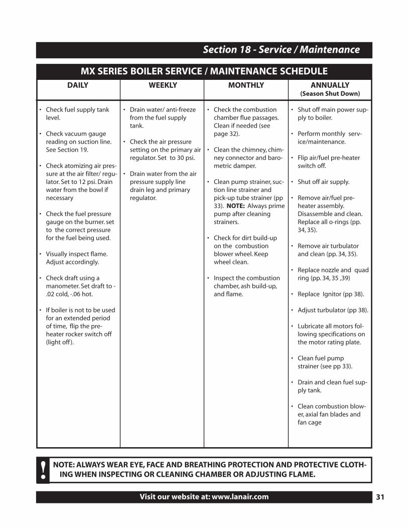
Flame is under-fired (Fig. 21).• The flame is like a blow torch.• Light yellow, to white in color.• Flame is too short.• Check to see if pre-heater block is hot.• Check air PSI, it may be too high. Adjust in 1 LB. increments.• Oil pressure and the combustion air baffle may need adjustment.
Problem: Too small a flame, similar to a blowtorch.1. Too much atomizing air pressure.2. Too much combustion air pressure.3. Not enough fuel pressure.
Solutions:1. Correct fuel pressure setting.2. Flame tips reach 3/4 of the way into the chamber.3. Flame has slightly yellow/orange tips.4. No black smoke coming from the chimney.5. Ash inside the chamber is white to off white in color.
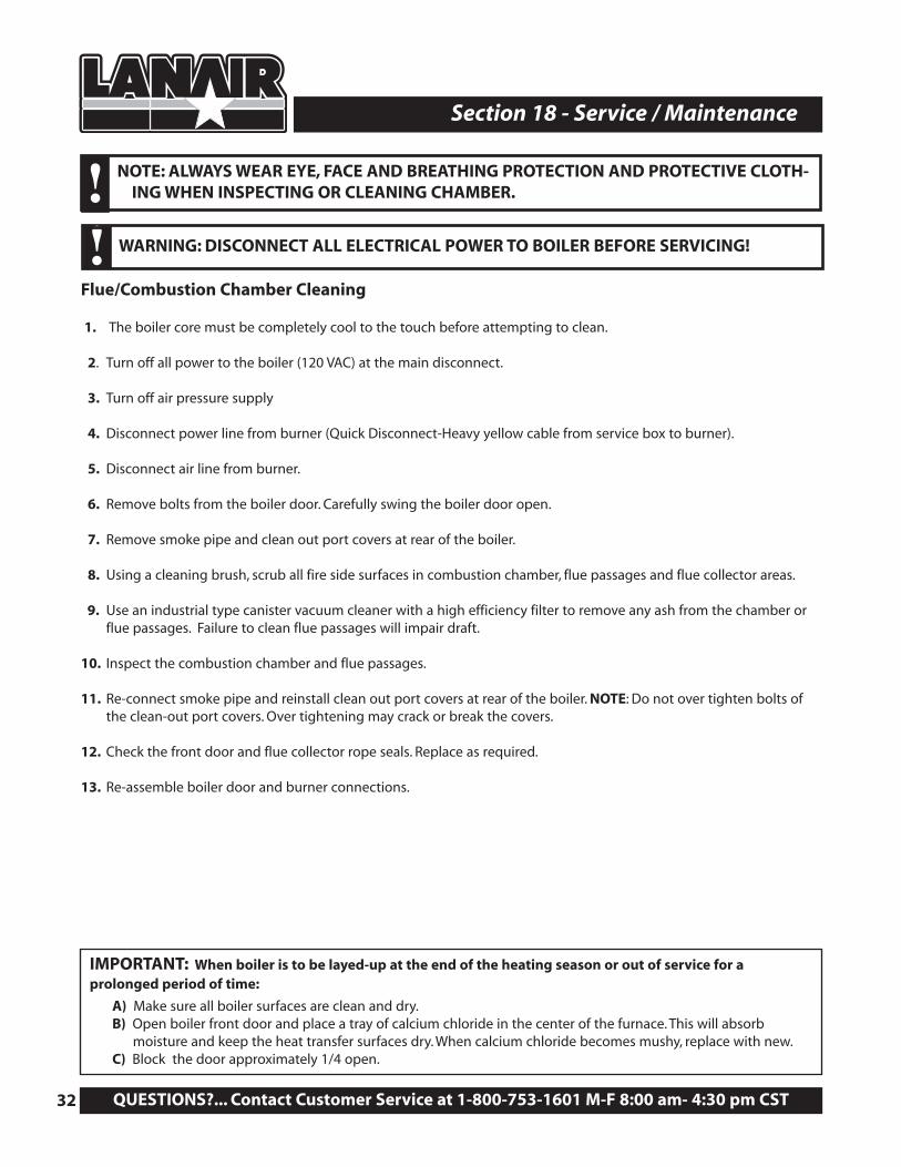
Flame is full (Fig. 22).• Bright yellow in color.• Flame extends 3/4 into the chamber.• Flame is not impinging on the chamber walls.
If you need assistance with flame adjustment, please call Lanair's Parts and Service Department.
CHECK FLAME DAILY (see page 31). ADJUST ACCORDINGLY!
DO NOT OVER FIRE YOUR BOILER. IMMEDIATELY ADJUST THE BURNER TO THE PROPER FLAME LENGTH TO PREVENT DAMAGE TO YOUR BOILER.!
Figure 20
Figure 21
Figure 22
BAD FLAMEThe flame is too big, creating an over-firecondition
BAD FLAMEThe flame is too short
GOOD FLAMEThe flame length is approximately 3/4 ofthe chamber
Visit our website at: www.lanair.com 31
Section 18 - Service / Maintenance
DAILY
• Check fuel supply tanklevel.
• Check vacuum gaugereading on suction line.See Section 19.
• Check atomizing air pres-sure at the air filter/ regu-lator. Set to 12 psi. Drainwater from the bowl ifnecessary
• Check the fuel pressuregauge on the burner. setto the correct pressurefor the fuel being used.
• Visually inspect flame.Adjust accordingly.
• Check draft using amanometer. Set draft to -.02 cold, -.06 hot.
• If boiler is not to be usedfor an extended periodof time, flip the pre-heater rocker switch off(light off ).
WEEKLY
• Drain water/ anti-freezefrom the fuel supplytank.
• Check the air pressuresetting on the primary airregulator. Set to 30 psi.
• Drain water from the airpressure supply linedrain leg and primaryregulator.
MONTHLY
• Check the combustionchamber flue passages.Clean if needed (seepage 32).
• Clean the chimney, chim-ney connector and baro-metric damper.
• Clean pump strainer, suc-tion line strainer andpick-up tube strainer (pp33). NOTE: Always primepump after cleaningstrainers.
• Check for dirt build-upon the combustionblower wheel. Keepwheel clean.
• Inspect the combustionchamber, ash build-up,and flame.
ANNUALLY (Season Shut Down)
• Shut off main power sup-ply to boiler.
• Perform monthly serv-ice/maintenance.
• Flip air/fuel pre-heaterswitch off.
• Shut off air supply.
• Remove air/fuel pre-heater assembly.Disassemble and clean.Replace all o-rings (pp.34, 35).
• Remove air turbulatorand clean (pp. 34, 35).
• Replace nozzle and quadring (pp. 34, 35 ,39)
• Replace Ignitor (pp 38).
• Adjust turbulator (pp 38).
• Lubricate all motors fol-lowing specifications onthe motor rating plate.
• Clean fuel pump strainer (see pp 33).
• Drain and clean fuel sup-ply tank.
• Clean combustion blow-er, axial fan blades andfan cage
NOTE: ALWAYS WEAR EYE, FACE AND BREATHING PROTECTION AND PROTECTIVE CLOTH-ING WHEN INSPECTING OR CLEANING CHAMBER OR ADJUSTING FLAME.!
MX SERIES BOILER SERVICE / MAINTENANCE SCHEDULE
QUESTIONS?... Contact Customer Service at 1-800-753-1601 M-F 8:00 am- 4:30 pm CST32
Section 18 - Service / Maintenance
Flue/Combustion Chamber Cleaning
1. The boiler core must be completely cool to the touch before attempting to clean.
2. Turn off all power to the boiler (120 VAC) at the main disconnect.
3. Turn off air pressure supply
4. Disconnect power line from burner (Quick Disconnect-Heavy yellow cable from service box to burner).
5. Disconnect air line from burner.
6. Remove bolts from the boiler door. Carefully swing the boiler door open.
7. Remove smoke pipe and clean out port covers at rear of the boiler.
8. Using a cleaning brush, scrub all fire side surfaces in combustion chamber, flue passages and flue collector areas.
9. Use an industrial type canister vacuum cleaner with a high efficiency filter to remove any ash from the chamber orflue passages. Failure to clean flue passages will impair draft.
10. Inspect the combustion chamber and flue passages.
11. Re-connect smoke pipe and reinstall clean out port covers at rear of the boiler. NOTE: Do not over tighten bolts ofthe clean-out port covers. Over tightening may crack or break the covers.
12. Check the front door and flue collector rope seals. Replace as required.
13. Re-assemble boiler door and burner connections.
NOTE: ALWAYS WEAR EYE, FACE AND BREATHING PROTECTION AND PROTECTIVE CLOTH-ING WHEN INSPECTING OR CLEANING CHAMBER.!
WARNING: DISCONNECT ALL ELECTRICAL POWER TO BOILER BEFORE SERVICING! !
IMPORTANT: When boiler is to be layed-up at the end of the heating season or out of service for a prolonged period of time:
A) Make sure all boiler surfaces are clean and dry.B) Open boiler front door and place a tray of calcium chloride in the center of the furnace. This will absorb
moisture and keep the heat transfer surfaces dry. When calcium chloride becomes mushy, replace with new.C) Block the door approximately 1/4 open.
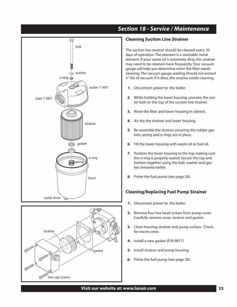
Cleaning Suction Line Strainer
The suction line strainer should be cleaned every 30 days of operation. The element is a washable metal element. If your waste oil is extremely dirty, this strainermay need to be cleaned more frequently. Your vacuumgauge will help you determine when the filter needs cleaning. The vacuum gauge reading should not exceed5" HG of vacuum. If it does, the strainer needs cleaning.
1. Disconnect power to the boiler.
2. While holding the lower housing, unscrew the cen-ter bolt on the top of the suction line strainer.
3. Rinse the filter and lower housing in solvent.
4. Air dry the strainer and lower housing.
5. Re-assemble the strainer, ensuring the rubber gas-kets, spring and o-rings are in place.
6. Fill the lower housing with waste oil or fuel oil.
7. Position the lower housing to the top making surethe o-ring is properly seated. Secure the top andbottom together using the bolt, washer and gas-ket removed earlier.
8. Prime the fuel pump (see page 28).
Cleaning/Replacing Fuel Pump Strainer
1. Disconnect power to the boiler.
2. Remove four hex head screws from pump cover.Carefully remove cover, strainer and gasket.
3. Clean housing, strainer and pump surface. Checkfor excess wear.
4. Install a new gasket (P/N 9817).
5. Install strainer and pump housing.
6. Prime the fuel pump (see page 28).
Visit our website at: www.lanair.com 33
Section 18 - Service / Maintenance
bolt
washer
o-ring
inlet 1” NPT
outlet 1” NPT
strainer
strainer
hex cap screws
gasket
gasket
o-ringspring
bowl
water drain
QU
ESTION
S?...Co
ntact C
usto
mer Service at 1
-80
0-7
53
-16
01
M-F 8
:00
am- 4
:30
pm
CST
34
Section
18 - Service / Ma
inten
an
ce1
2
3
4
5
6
7
913
14
15
18
19
20
12
17
1611
10
8
22
See pages 36-37 for requiredannual oil block maintenance
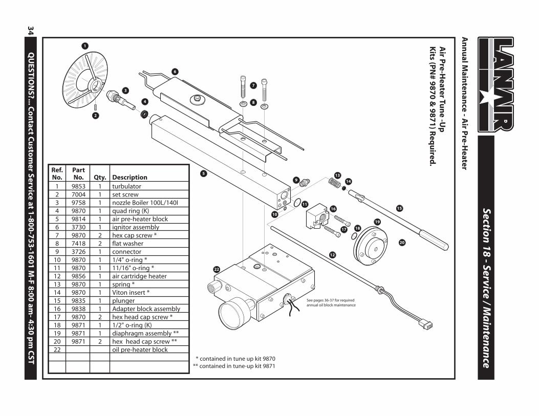
Ref. PartNo. No. Qty. Description
1 9853 1 turbulator2 7004 1 set screw3 9758 1 nozzle Boiler 100L/140I4 9870 1 quad ring (K)5 9814 1 air pre-heater block6 3730 1 ignitor assembly7 9870 2 hex cap screw *8 7418 2 flat washer9 3726 1 connector
10 9870 1 1/4" o-ring *11 9870 1 11/16" o-ring *12 9856 1 air cartridge heater13 9870 1 spring *14 9870 1 Viton insert *15 9835 1 plunger16 9838 1 Adapter block assembly17 9870 2 hex head cap screw *18 9871 1 1/2" o-ring (K)19 9871 1 diaphragm assembly **20 9871 2 hex head cap screw **22 oil pre-heater block
An
nu
al Main
tenan
ce - Air P
re-Heater
Air P
re-Heater Tu
ne -U
p
Kits (P
N# 9
87
0 &
98
71
) Req
uired
.
* contained in tune up kit 9870** contained in tune-up kit 9871
1. Remove Pre-Heater Assembly• Disconnect the air line from the brass fitting on the air pre-heater and then from
the air solenoid and remove.• Disconnect wiring from the oil pre-heater cartridge, air pre-heater cartridge and
snap disc assembly in the wiring junction box.• Disconnect fuel line and fitting (6) from the oil block (5).• Disconnect fuel pressure gauge (8) and fitting from the oil block (5).• Remove button hex screw (14) and washer (11).• Lift pre-heater assembly and carefully pull straight back. Remove entire assembly
from the burner.• Remove ignitor assembly (6).
2. Remove Diaphragm Assembly from Air Pre-Heater• Carefully place pre-heater assembly in a vice. NOTE: Do not damage pre-heater.• Unscrew diaphragm assembly (19) from air pre-heater and set aside. Remove o-ring
and discard.
3. Remove Adapter Assembly• Remove hex cap screws (17) and set adapter assembly aside.
4. Remove Plunger , Spring and Cartridge Heater• Remove spring (13) from plunger (15) and discard.• Using a hook or screwdriver, carefully remove Viton insert (14) and discard.• Remove and discard 1/4" o-ring (10) and 11/16" o-ring (11).• Loosen and remove cartridge heater and set aside.
5. Remove Nozzle Assembly and Quad Ring• Remove nozzle assembly (3) using a 9/16" wrench.• If quad ring (4) does not come out with nozzle, carefully remove it and discard.
6. Clean all parts using a parts washer• All passages must be thoroughly cleaned with a brush.
7. Replace Nozzle Assembly and Quad Ring• After cleaning air pre-heater assembly, blow dry.• Install new quad ring (4). Before inserting quad ring in air pre-heater block, a light coat of oil should be
applied. NOTE: Make sure quad ring is properly seated in block before proceeding (see page 39 for clarification).• Apply a light coat of oil to the shaft of the new nozzle assembly (3). Carefully insert new nozzle assembly (3)
through the quad ring and into the block. Hand tighten until snug.• Check alignment of ignitors and adjust if necessary (see page 38).
8. Replace O-rings and Plunger• Insert a new 1/4" o-ring (10) and a new 11/16" o-ring (11) into the air pre-heater block (5).• Insert new Viton insert (14) into the end of the plunger (15) and place new spring (13) on the end of the
plunger. Insert plunger into air pre-heater block spring end first.
9. Replace Cartridge Heater• Apply pipe dope to cartridge heater threads. Insert cartridge heater into air pre-heater block and tighten.
10. Replace Adapter Assembly• Align the holes of the adapter assembly (16) with those on the air pre-heater block (5). NOTE: Make
sure the small end of the adapter pin is facing toward the air pre-heater block.• Attach the Adapter assembly (16) to the block using two hex cap screws (17). Tighten screws.
11. Replace Diaphragm • Replace diaphragm, o-ring and spring (see page 39) Re-attach diaphragm assembly and hand tighten.
NOTE: Do not over tighten.
12. Replace Ignitor Assembly (see page 39)
13. Service Oil Pre-Heater (see pages 36-37 for Annual Maintenance Instructions)
Visit our website at: www.lanair.com 35
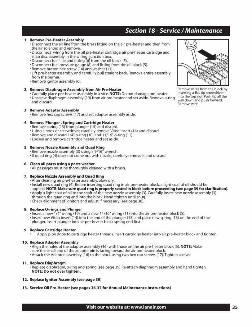
Section 18 - Service / Maintenance
Remove wires from the block byinserting a flat tip screwdriverinto the top slot. Push tip all theway down and push forward.Remove wire.
QUESTIONS?... Contact Customer Service at 1-800-753-1601 M-F 8:00 am- 4:30 pm CST36
Section 18 - Service / Maintenance
6
8
12
7
9
5
2
3
1
4
6
7
12
10
12
13
14
11
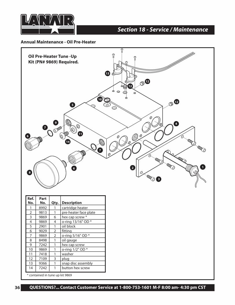
Ref. PartNo. No. Qty. Description
1 8992 1 cartridge heater2 9813 1 pre-heater face plate3 9869 6 hex cap screw *4 9869 4 o-ring 13/16" OD *5 2901 1 oil block6 9029 2 fitting7 9869 2 o-ring 5/16" OD *8 8498 1 oil gauge9 7242 1 hex cap screw
10 9869 1 o-ring 1/2" OD *11 7418 1 washer12 7109 3 plug13 9366 1 snap disc assembly14 7242 1 button hex screw
Annual Maintenance - Oil Pre-Heater
Oil Pre-Heater Tune -Up Kit (PN# 9869) Required.
* contained in tune up kit 9869
1. Separate Air Pre-Heater from Oil Pre-Heater• Remove o-ring and discard(10).
2. Disassemble Oil Pre-Heater• Remove o-ring and discard(10).• Remove six hex cap screws (3) from face plate (2) and discard.• Remove oil cartridge heater (1).• Remove four 13/16"OD o-rings and discard(4).• Remove three plugs (12) from oil block (5)• Remove hex cap screw (9) from inside oil pre-heater block and clean. NOTE: Do not discard (5).
3. Clean Oil Pre-Heater Block• Clean oil pre-heater block using a parts washer and brush. NOTE: Make sure all passages are clean.• Blow dry the oil pre-heater block. inspect ALL passages making sure they are clear and clean.
4. Reassemble Oil Pre-Heater• Replace four 13/16" OD o-rings (4) with new.• Replace cartridge heater. NOTE: Do not over-tighten.• Re-attach face plate (2) using six new hex cap screws (3) provided with tune-up kit (P/N 7240).• Apply loc-tite to three block plugs (12) and replace.• Replace hex cap screw (9) inside oil pre-heater block (5).• Replace o-ring (10) with new.
5. Attach Air Pre-Heater Assembly• Align the holes of the ignitor assembly and air pre-heater with those of the oil pre-heater (see page 34).• Attach air pre-heater assembly to the oil pre-heater block (5) using two hex cap screws. Tighten securely.
6. Re-install Pre-Heater Assembly• Place the air/oil pre-heater assembly into the burner body.• Align the holes of the pre-heater assembly with those in the burner body.• Secure the assembly to the body by re-installing the button hex screw (14) and washer (11). NOTE:Do not tighten
this screw at this time.• Replace the o-rings (7) on the PSI gauge and the oil line fittings (6) with new. NOTE:Do not tighten these fittings at
this time.• Adjust the pre-heater assembly for proper setting. The end of the turbulator should be recessed approximately 1/4"
into the burner tube (see page 38 for turbulator adjustment).• Once adjusted tighten button hex screw (14) and fittings (6)securely.
7. Re-connect Electrical• Re-connect all wires previously disconnected in the electrical junction box (refer to wiring diagram, page 23 and
the burner reference diagram, page 43).
8. Reconnect PSI Gauge, Fuel Line and Air Line• Reconnect the PSI gauge (8) to the fitting (6) and tighten securely.• Reconnect the fuel line to the fitting (6) and tighten securely.• Reconnect the air line by connecting the one end of the air line to the air solenoid and the other end to the
air fitting (see page 34).
9. Test Operation• Follow start-up procedure, page 26.
Visit our website at: www.lanair.com 37
Section 18 - Service / Maintenance
QUESTIONS?... Contact Customer Service at 1-800-753-1601 M-F 8:00 am- 4:30 pm CST38
Section 18 - Service / Maintenance
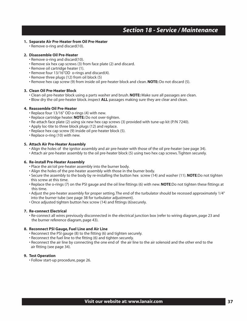
Turbulator 1/4” max. fromend of the tube
Pre-heater Assemblyadjustment screw
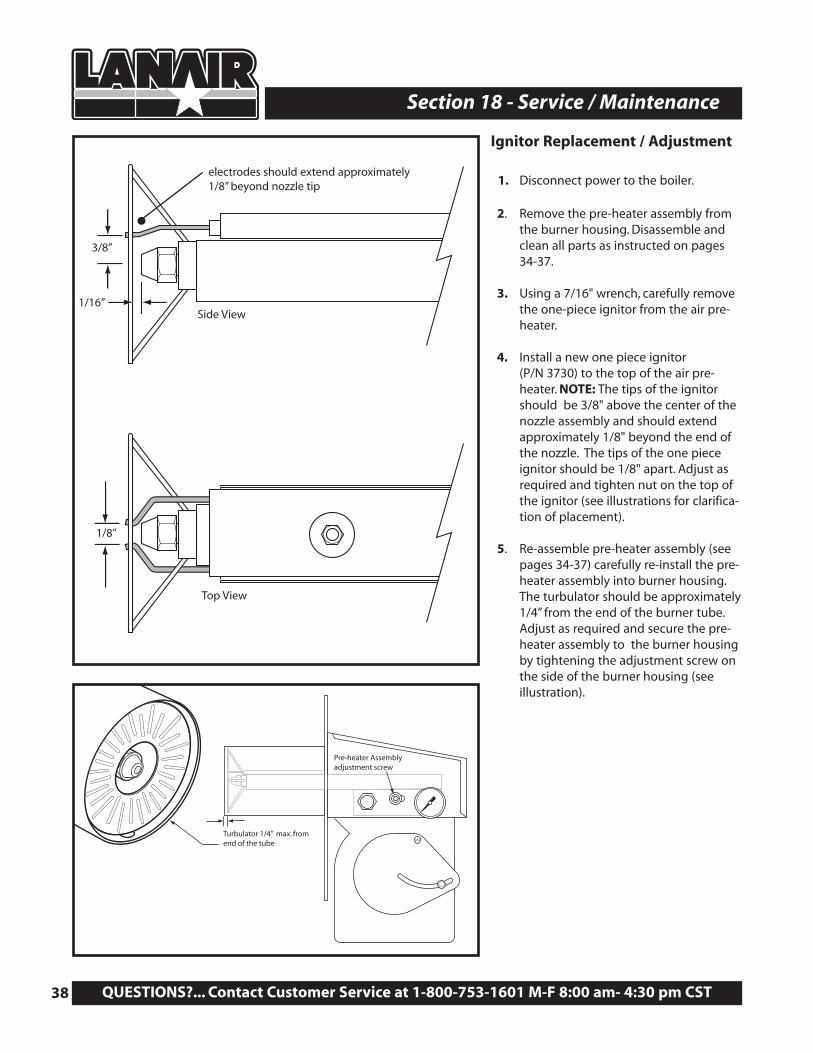
Ignitor Replacement / Adjustment
1. Disconnect power to the boiler.
2. Remove the pre-heater assembly fromthe burner housing. Disassemble andclean all parts as instructed on pages 34-37.
3. Using a 7/16" wrench, carefully removethe one-piece ignitor from the air pre-heater.
4. Install a new one piece ignitor (P/N 3730) to the top of the air pre-heater. NOTE: The tips of the ignitorshould be 3/8" above the center of thenozzle assembly and should extendapproximately 1/8" beyond the end ofthe nozzle. The tips of the one pieceignitor should be 1/8" apart. Adjust asrequired and tighten nut on the top ofthe ignitor (see illustrations for clarifica-tion of placement).
5. Re-assemble pre-heater assembly (seepages 34-37) carefully re-install the pre-heater assembly into burner housing.The turbulator should be approximately1/4” from the end of the burner tube.Adjust as required and secure the pre-heater assembly to the burner housingby tightening the adjustment screw onthe side of the burner housing (seeillustration).
electrodes should extend approximately1/8” beyond nozzle tip
3/8”
1/16”Side View
Top View
1/8”
Visit our website at: www.lanair.com 39
Section 18 - Service / Maintenance
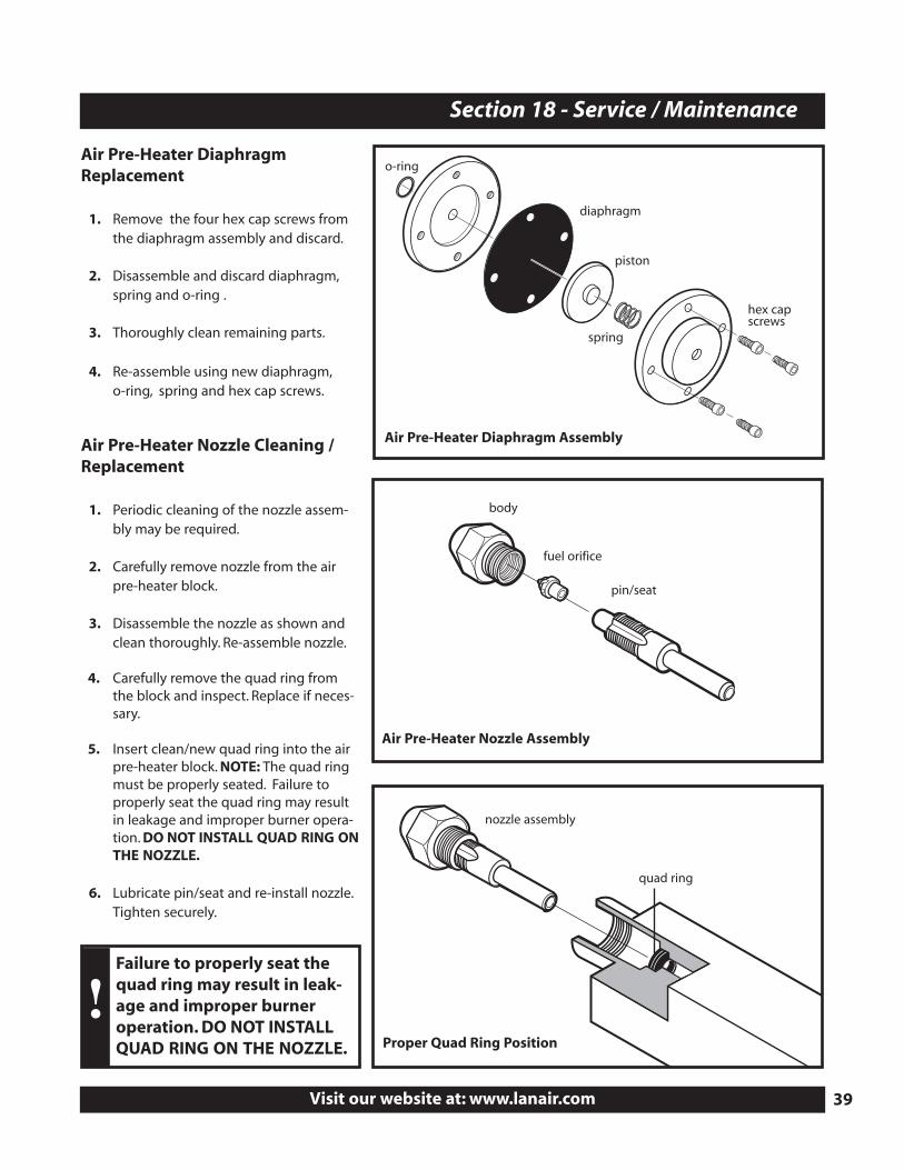
Air Pre-Heater DiaphragmReplacement
1. Remove the four hex cap screws fromthe diaphragm assembly and discard.
2. Disassemble and discard diaphragm,spring and o-ring .
3. Thoroughly clean remaining parts.
4. Re-assemble using new diaphragm,o-ring, spring and hex cap screws.
Air Pre-Heater Nozzle Cleaning /Replacement
1. Periodic cleaning of the nozzle assem-bly may be required.
2. Carefully remove nozzle from the airpre-heater block.
3. Disassemble the nozzle as shown andclean thoroughly. Re-assemble nozzle.
4. Carefully remove the quad ring fromthe block and inspect. Replace if neces-sary.
5. Insert clean/new quad ring into the airpre-heater block. NOTE: The quad ringmust be properly seated. Failure toproperly seat the quad ring may resultin leakage and improper burner opera-tion. DO NOT INSTALL QUAD RING ONTHE NOZZLE.
6. Lubricate pin/seat and re-install nozzle.Tighten securely.
Air Pre-Heater Diaphragm Assembly
Air Pre-Heater Nozzle Assembly
Proper Quad Ring Position
diaphragm
fuel orifice
body
pin/seat
nozzle assembly
quad ring
piston
spring
hex capscrews
o-ring
!Failure to properly seat thequad ring may result in leak-age and improper burneroperation. DO NOT INSTALLQUAD RING ON THE NOZZLE.
QUESTIONS?... Contact Customer Service at 1-800-753-1601 M-F 8:00 am- 4:30 pm CST40
Section 19 - Troubleshooting
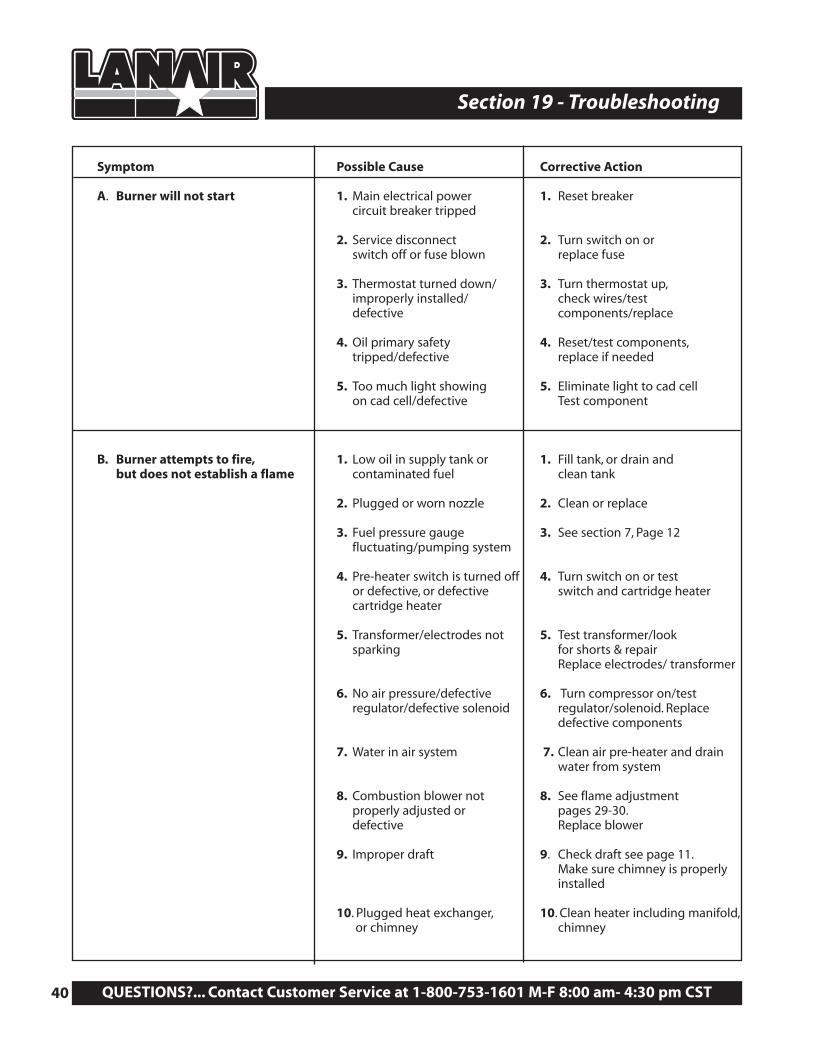
Symptom Possible Cause Corrective Action
A. Burner will not start 1. Main electrical power 1. Reset breakercircuit breaker tripped
2. Service disconnect 2. Turn switch on or switch off or fuse blown replace fuse
3. Thermostat turned down/ 3. Turn thermostat up,improperly installed/ check wires/test defective components/replace
4. Oil primary safety 4. Reset/test components,tripped/defective replace if needed
5. Too much light showing 5. Eliminate light to cad cellon cad cell/defective Test component
B. Burner attempts to fire, 1. Low oil in supply tank or 1. Fill tank, or drain and but does not establish a flame contaminated fuel clean tank
2. Plugged or worn nozzle 2. Clean or replace
3. Fuel pressure gauge 3. See section 7, Page 12fluctuating/pumping system
4. Pre-heater switch is turned off 4. Turn switch on or test or defective, or defective switch and cartridge heater cartridge heater
5. Transformer/electrodes not 5. Test transformer/look sparking for shorts & repair
Replace electrodes/ transformer
6. No air pressure/defective 6. Turn compressor on/test regulator/defective solenoid regulator/solenoid. Replace
defective components
7. Water in air system 7. Clean air pre-heater and drain water from system
8. Combustion blower not 8. See flame adjustment properly adjusted or pages 29-30.defective Replace blower
9. Improper draft 9. Check draft see page 11.Make sure chimney is properly installed
10. Plugged heat exchanger, 10. Clean heater including manifold,or chimney chimney
Visit our website at: www.lanair.com 41
Section 19 - Trouble-Shooting
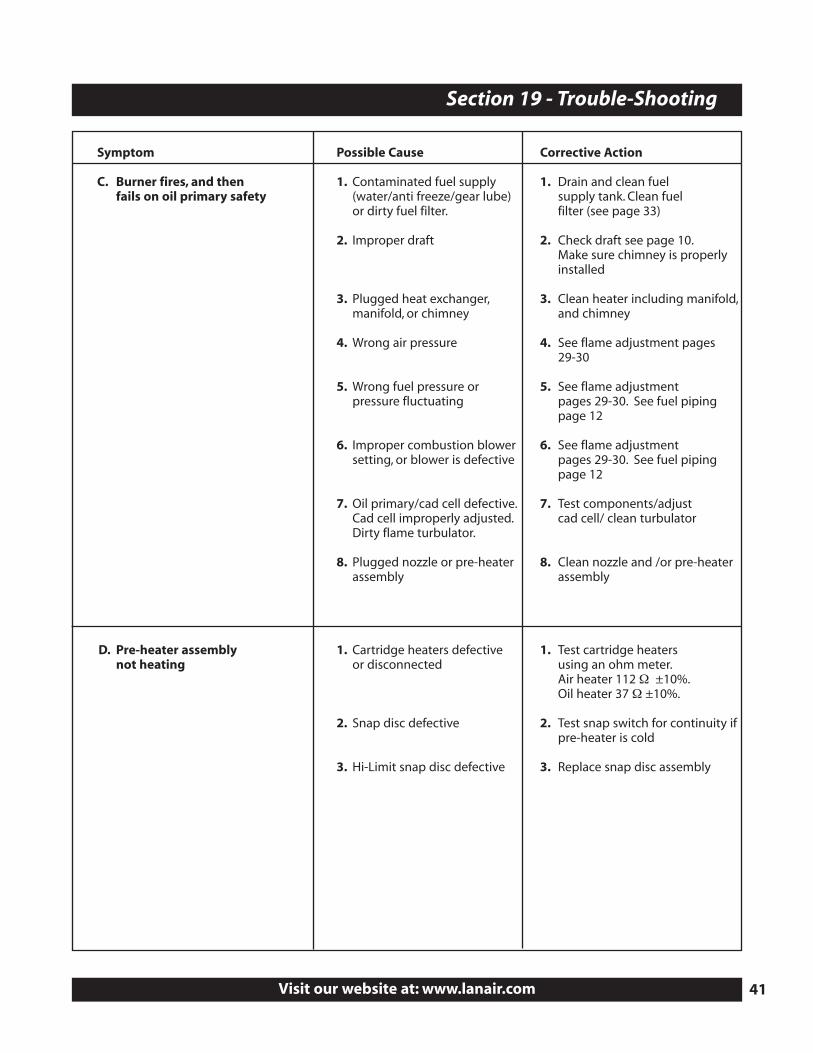
Symptom Possible Cause Corrective Action
C. Burner fires, and then 1. Contaminated fuel supply 1. Drain and clean fuel fails on oil primary safety (water/anti freeze/gear lube) supply tank. Clean fuel
or dirty fuel filter. filter (see page 33)
2. Improper draft 2. Check draft see page 10.Make sure chimney is properly installed
3. Plugged heat exchanger, 3. Clean heater including manifold,manifold, or chimney and chimney
4. Wrong air pressure 4. See flame adjustment pages 29-30
5. Wrong fuel pressure or 5. See flame adjustment pressure fluctuating pages 29-30. See fuel piping
page 12
6. Improper combustion blower 6. See flame adjustment setting, or blower is defective pages 29-30. See fuel piping
page 12
7. Oil primary/cad cell defective. 7. Test components/adjust Cad cell improperly adjusted. cad cell/ clean turbulatorDirty flame turbulator.
8. Plugged nozzle or pre-heater 8. Clean nozzle and /or pre-heaterassembly assembly
D. Pre-heater assembly 1. Cartridge heaters defective 1. Test cartridge heaters not heating or disconnected using an ohm meter.
Air heater 112 Ω ±10%.Oil heater 37 Ω ±10%.
2. Snap disc defective 2. Test snap switch for continuity if pre-heater is cold
3. Hi-Limit snap disc defective 3. Replace snap disc assembly
QUESTIONS?... Contact Customer Service at 1-800-753-1601 M-F 8:00 am- 4:30 pm CST42
Section 20 - Warranty
Items Not Covered Under Warranty
Conditions That Will Void Warranty
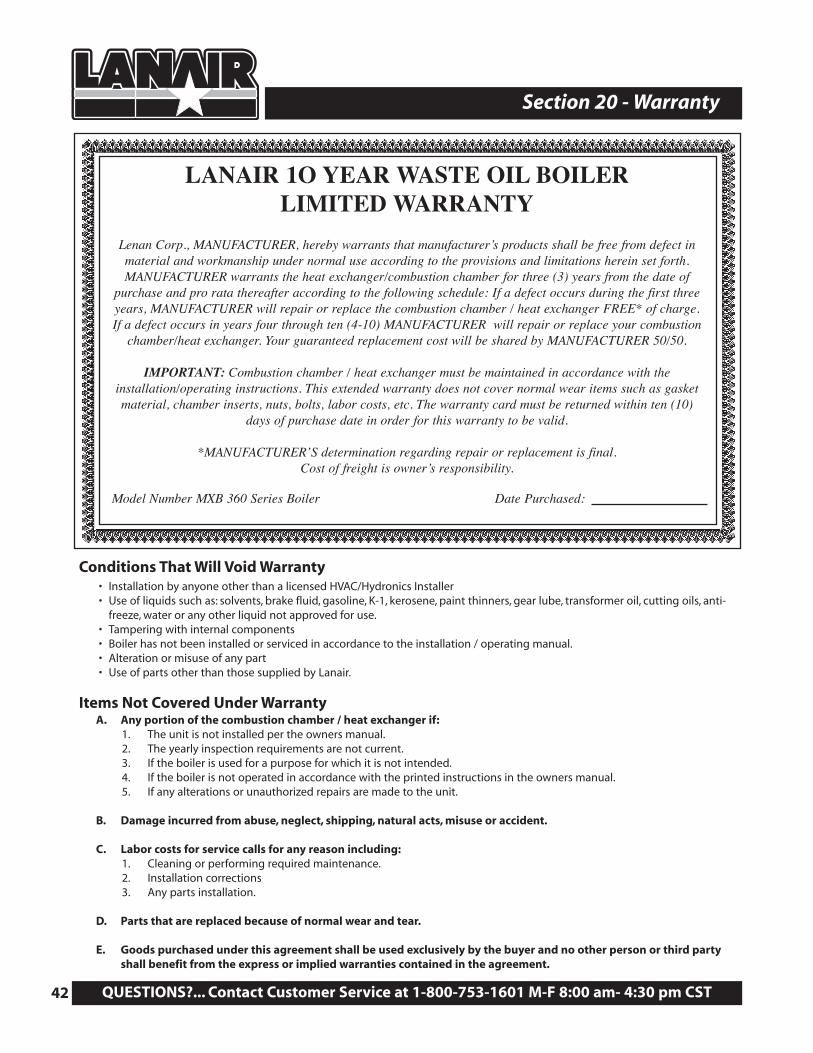
LANAIR 1O YEAR WASTE OIL BOILERLIMITED WARRANTY
Lenan Corp., MANUFACTURER, hereby warrants that manufacturer’s products shall be free from defect in material and workmanship under normal use according to the provisions and limitations herein set forth. MANUFACTURER warrants the heat exchanger/combustion chamber for three (3) years from the date of
purchase and pro rata thereafter according to the following schedule: If a defect occurs during the first threeyears, MANUFACTURER will repair or replace the combustion chamber / heat exchanger FREE* of charge.If a defect occurs in years four through ten (4-10) MANUFACTURER will repair or replace your combustion
chamber/heat exchanger. Your guaranteed replacement cost will be shared by MANUFACTURER 50/50.
IMPORTANT: Combustion chamber / heat exchanger must be maintained in accordance with the installation/operating instructions. This extended warranty does not cover normal wear items such as gasket material, chamber inserts, nuts, bolts, labor costs, etc. The warranty card must be returned within ten (10)
days of purchase date in order for this warranty to be valid.
*MANUFACTURER’S determination regarding repair or replacement is final. Cost of freight is owner’s responsibility.
Model Number MXB 360 Series Boiler Date Purchased:
A. Any portion of the combustion chamber / heat exchanger if:1. The unit is not installed per the owners manual.2. The yearly inspection requirements are not current.3. If the boiler is used for a purpose for which it is not intended.4. If the boiler is not operated in accordance with the printed instructions in the owners manual.5. If any alterations or unauthorized repairs are made to the unit.
B. Damage incurred from abuse, neglect, shipping, natural acts, misuse or accident.
C. Labor costs for service calls for any reason including:1. Cleaning or performing required maintenance.2. Installation corrections3. Any parts installation.
D. Parts that are replaced because of normal wear and tear.
E. Goods purchased under this agreement shall be used exclusively by the buyer and no other person or third partyshall benefit from the express or implied warranties contained in the agreement.
• Installation by anyone other than a licensed HVAC/Hydronics Installer• Use of liquids such as: solvents, brake fluid, gasoline, K-1, kerosene, paint thinners, gear lube, transformer oil, cutting oils, anti-
freeze, water or any other liquid not approved for use.• Tampering with internal components• Boiler has not been installed or serviced in accordance to the installation / operating manual.• Alteration or misuse of any part• Use of parts other than those supplied by Lanair.
Visit our website at: www.lanair.com
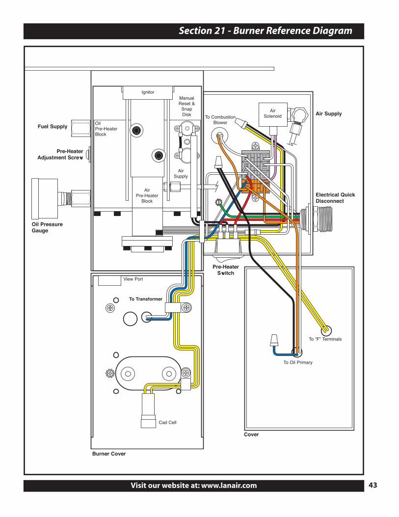
Section 21 - Burner Reference Diagram
Oil PressureGauge
ManualReset &
SnapDisk
Fuel Supply
Pre-HeaterAdjustment Screw
To CombustionBlower
Pre-HeaterSwitch
Air Supply
AirSupply
AirSolenoid
Ignitor
Oil Pre-HeaterBlock
Air Pre-Heater
Block
To Oil Primary
To “F” Terminals
To Transformer
Cover
Burner Cover
View Port
Cad Cell
Electrical QuickDisconnect
43
®
Lanair Waste Oil Heaters & Boilers4109 Capital Circle
Janesville, Wisconsin 53546608-752-1601
www.lanair.com
© 2004 Martrade LLC Lanair is a registered trademark of Martrade LLC P/N 5050