mwm catalogo 2015 1 - mwm freni e frizioni · mwm cat 2015_1 copertina 7-10-2014 12:17 pagina 1...
TRANSCRIPT
MWM cat 2015_1 copertina 7-10-2014 12:17 Pagina 1
Colori compositi
C M Y CM MY CY CMY K
FRENIFRIZIONIINNESTI A DENTIGIUNTI LIMITATORI DI COPPIAA COMANDO OLEODINAMICO E PNEUMATICO
BRAKESCLUTCHES
TOOTH-TYPE COUPLINGSTORQUE LIMITING COUPLINGS
HYDRAULICALLY AND PNEUMATICALLY CONTROLLED
CATALOGO 2015.1MWM FRENI FRIZIONI S.r.l.20148 MILANO (ITALY) - VIA CACCIALEPORI, 18Tel. 02.40.07.08.45 - 02.48.70.60.44 - Fax 02.40.78.041
CATA
LO
GO
201
5.1
MWM produce:
• Giunti limitatori di coppia • Freni • Frizioni• Innesti • Unità combinate
a comando:• meccanico • pneumatico • oleodinamico
• elettromagnetico
prodotti di serie e ad-hoc.
MWM produces:
• Torque limiting joints • Brakes • Clutches• Couplings • Combined units
actuated by:• hand (mechanical) • air (pneumatic)
• oil (hydraulic) • voltage (electromagnetic)
by catalogue or made ad-hoc.
Richiedi i nostri cataloghiAsk for our catalogues
1
Anni di esperienza nel settore ci hanno con-sentito di conseguire considerevoli risultati,sia nelle normali costruzioni, che nelleapplicazioni appositamente elaborate dalnostro Ufficio Tecnico allo scopo di risolve-re particolari problemi e di soddisfare esi-genze complesse.Siamo pertanto in grado di fornire anchegruppi completi monoblocco - cambi divelocità - invertitori - prese di forza, oltreche costruire innesti a frizione aventi carat-teristiche diverse da quelle riportate dalletabelle del presente catalogo.
Our many years of experience in this fieldhas permitted us to obtain considerableresults, both as regards standard construc-tions and the applications that have beenspecially designed by our EngineeringDept. for solving particular problems andsatisfaying complex requirements.We are therefore in a position to also fur-nish complete units - such as gearboxes,inverters and power grips, as well as frictioncouplings having different characteristicsfrom those shown in the present catalogue.
MWM FRENI-FRIZIONI S.R.L.
GIUNTI LIMITATORI DI COPPIAFRENI, FRIZIONI MONODISCO E MULTIDISCOINNESTI A DENTIPOSITIVI E A PRESSIONE DI MOLLEA COMANDO OLEODINAMICO E PNEUMATICO
TORQUE LIMITING COUPLINGSBRAKES AND CLUTCHES SINGLE-PLATE AND MULTI-DISK,TOOTH-TYPE COUPLINGSSPRING RELEASED AND SPRING APPLIEDHYDRAULICALLY AND PNEUMATICALLY CONTROLLED
GIUNTI LIMITATORI DI COPPIAFRENI, FRIZIONI MONODISCO E MULTIDISCOINNESTI A DENTIPOSITIVI E A PRESSIONE DI MOLLEA COMANDO OLEODINAMICO E PNEUMATICO
TORQUE LIMITING COUPLINGSBRAKES AND CLUTCHES SINGLE-PLATE AND MULTI-DISK,TOOTH-TYPE COUPLINGSSPRING RELEASED AND SPRING-APPLIEDHYDRAULICALLY AND PNEUMATICALLY CONTROLLED
CATALOGO GENERALE2015.1
MASTER CATALOGUE
MWM FRENI FRIZIONI S.R.L.I-20148 MILANO - VIA CACCIALEPORI, 18 - TEL. 02.40.07.08.45 r.a. FAX 02.40.78.041
2
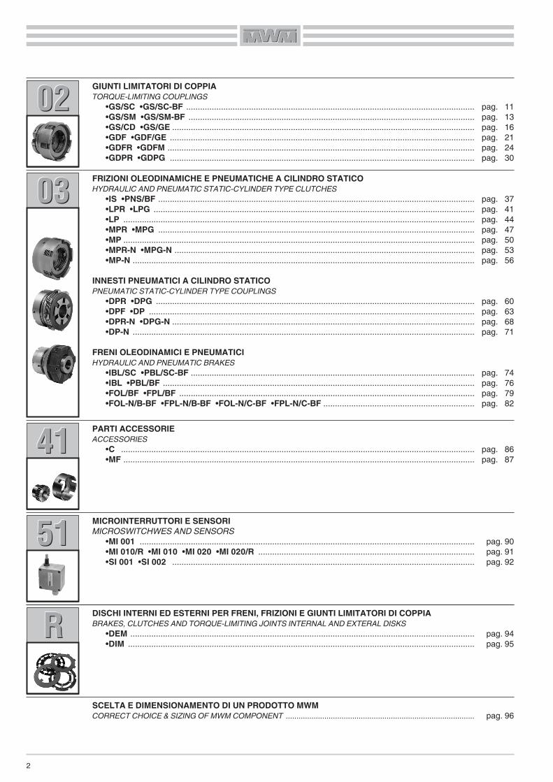
GIUNTI LIMITATORI DI COPPIATORQUE-LIMITING COUPLINGS
•GS/SC •GS/SC-BF ............................................................................................................................•GS/SM •GS/SM-BF ...........................................................................................................................•GS/CD •GS/GE ..................................................................................................................................•GDF •GDF/GE ...................................................................................................................................•GDFR •GDFM ....................................................................................................................................•GDPR •GDPG ...................................................................................................................................
pag. 11pag. 13pag. 16pag. 21pag. 24pag. 30
020202
FRIZIONI OLEODINAMICHE E PNEUMATICHE A CILINDRO STATICOHYDRAULIC AND PNEUMATIC STATIC-CYLINDER TYPE CLUTCHES
•IS •PNS/BF ........................................................................................................................................•LPR •LPG ..........................................................................................................................................•LP .......................................................................................................................................................•MPR •MPG ........................................................................................................................................•MP .......................................................................................................................................................•MPR-N •MPG-N .................................................................................................................................•MP-N ...................................................................................................................................................
INNESTI PNEUMATICI A CILINDRO STATICOPNEUMATIC STATIC-CYLINDER TYPE COUPLINGS
•DPR •DPG .........................................................................................................................................•DPF •DP ............................................................................................................................................•DPR-N •DPG-N ..................................................................................................................................•DP-N ...................................................................................................................................................
FRENI OLEODINAMICI E PNEUMATICIHYDRAULIC AND PNEUMATIC BRAKES
•IBL/SC •PBL/SC-BF ..........................................................................................................................•IBL •PBL/BF ......................................................................................................................................•FOL/BF •FPL/BF ...............................................................................................................................•FOL-N/B-BF •FPL-N/B-BF •FOL-N/C-BF •FPL-N/C-BF .................................................................
pag. 37pag. 41pag. 44pag. 47pag. 50pag. 53pag. 56
pag. 60pag. 63pag. 68pag. 71
pag. 74pag. 76pag. 79pag. 82
030303
PARTI ACCESSORIEACCESSORIES
•C ........................................................................................................................................................•MF .......................................................................................................................................................
pag. 86pag. 87
414141
DISCHI INTERNI ED ESTERNI PER FRENI, FRIZIONI E GIUNTI LIMITATORI DI COPPIABRAKES, CLUTCHES AND TORQUE-LIMITING JOINTS INTERNAL AND EXTERAL DISKS
•DEM ....................................................................................................................................................•DIM .....................................................................................................................................................
pag. 94pag. 95
RRR
SCELTA E DIMENSIONAMENTO DI UN PRODOTTO MWMCORRECT CHOICE & SIZING OF MWM COMPONENT ........................................................................................ pag. 96
MICROINTERRUTTORI E SENSORIMICROSWITCHWES AND SENSORS
•MI 001 ................................................................................................................................................•MI 010/R •MI 010 •MI 020 •MI 020/R .............................................................................................•SI 001 •SI 002 ..................................................................................................................................
pag. 90pag. 91pag. 92
515151

3
INTRODUZIONENella nostra produzione, distinguiamo gli organi di trasmissionein base alla modalità di trasmissione della coppia:
– trasmissione per attrito (frizioni)– trasmissione a dentini frontali (innesti)
I giunti limitatori di coppia, essendo disponibili con modelli siamultidisco o con guarnizioni d’attrito, sia con modelli a dentini,rientrano in entrambe le categorie.Le frizioni possono essere comandate oleodinamicamente opneumaticamente e sono in grado di accoppiare due cinemati-smi rotanti con velocità relative diverse (accoppiamenti dinamici)Gli innesti a dentini possono essere comandati come le frizionied anche loro servono a collegare due cinematismi meccanicirotanti con velocità sincrona oppure con minima differenza divelocità, meglio se da fermo.Nelle applicazioni dove è previsto per le frizioni un elevato riscal-damento , dovuto ad un eccessivo lavoro dinamico oppure adun’elevata frequenza di manovre, è consigliabile il funzionamen-to con lubrificazione, in modo da ottenere rapidamente lo smalti-mento del calore prodotto.Quando, per ragioni di sicurezza, sono necessari interventi inassenza di pressione, possono essere impiegati freni, frizioni edinnesti a pressione di molle, nelle versioni per funzionamento asecco o con lubrificazione.Per garantire il collegamento di due cinematismi in una posizio-ne fissa, si devono usare innesti a dentini con una o più fasi.
INTRODUCTIONIn our production, we distinguish transmission componentsaccording to torque transmission method:– torque transmitted by means of friction (clutches)– torque transmitted by toothing (tooth-type couplings)
Because they are available either in multi-disk and with frictionring either in tooth-type variants, torque limiting couplingsbelong to both categories.Clutches can be controlled hydraulically or pneumatically andthe rotating parts being coupled can also have relative motionbetween them (dynamic coupling)Tooth-type couplings can be controlled in the same manner ofclutches, but in this case, velocity of the two coupled parts has tobe synchronous or kept to a minimum, best of all if the couplingoccurs at rest.In all those applications where clutches, brakes and laminar cou-plings are subjected to excessive dynamic loads or high operat-ing frequencies, lubrication is recommended to rapidly dissipatethe generated heat.
For safety reasons, when operations must be performed withoutcommands, the thrust-spring type of brake, clutch or coupling isrecommended, either in the dry or lubricated version.
To assure connection at a precise fixed point between two rotat-ing parts, coupling unit with one or more phases must be used.
SCELTADovendo applicare un freno, una frizione o un innesto debbonoessere tenuti ben presenti i seguenti fattori:
1. Tipo di macchina2. Applicazione in scatola chiusa, con lubrificazione o a secco3. Tipo di comando disponibile, a seconda del tipo di macchina
o cinematismo4. Spazio a disposizione5. Grandezza di massima della potenza da trasmettere6. Numero degli interventi
La conoscenza dei dati sopra citati permetterà di scegliere il tipodi freno, frizione o innesto più adatto ad assolvere nel migliormodo alla funzione richiesta.A questo punto si dovrà calcolare la grandezza e per questo sarànecessario conoscere i seguenti dati tecnici:– Tipo di motore– Potenza motore in kW– Numero giri/minuto dell’albero freno o frizione o innesto– Numero interventi/ora ad intervalli costanti, oppure numero
interventi massimi al minuto e precisione richiesta– Momento d’inerzia J delle masse– Tempi d’accelerazione o di decelerazione
SELECTIONIn any application involving a brake, clutch or coupling unit, thefollowing important factors must be considered:
1. Type of machine2. If the application is enclosed, with or without lubrication.3. Type of controls available, according to the type of machine
or mechanical action.4. Available space.5. Overall maximum power to be transmitted.6. Number of work phases.
When all these data are obtained, the right type of brake, clutchor coupling unit can be selected.Then, proceeding with the size calculation, the following techni-cal data have to be obtained:– Type of motor– Motor power in kW– R.P.M. of the brake, clutch or coupling unit.– Regular interventions per hour (or maximum interventions perminute) and degree of required precision.
– Moment of inertia J– Acceleration or braking times
4
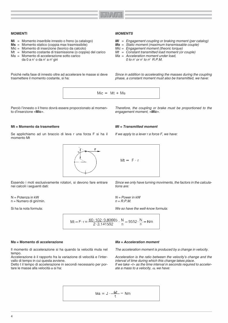
MOMENTIMi = Momento inseribile innesto o freno (a catalogo)Ms = Momento statico (coppia max trasmissibile)Mic = Momento di inserzione (teorico da calcolo)Mt = Momento costante di trasmissione (o coppia) del caricoMa = Momento di accelerazione sotto carico
da 0 a n1 o da n1 a n2 giri
Poichè nella fase di innesto oltre ad accelerare le masse si devetrasmettere il momento costante, si ha:
Perciò l’innesto o il freno dovrà essere proporzionato al momen-to d’inserzione «Mic».
Mt = Momento da trasmettereSe applichiamo ad un braccio di leva r una forza F si ha ilmomento Mt
Essendo i moti esclusivamente rotatori, si devono fare entrarenei calcoli i seguenti dati:
N = Potenza in kWn = Numero di giri/min.Si ha la nota formula:
Ma = Momento di accelerazioneIl momento di accelerazione si ha quando la velocità muta neltempo.Accelerazione è il rapporto fra la variazione di velocità e l’inter-vallo di tempo in cui questa avviene.Detto t il tempo di accelerazione in secondi necessario per por-tare le masse alla velocità ω si ha:
MOMENTSMi = Engagement coupling or braking moment (per catalog)Ms = Static moment (maximum transmissable couple)Mic = Engagement moment (theoric torque)Mt = Constant transmitted load moment (or couple)Ma = Acceleration moment under load,
0 to n1 or n1 to n2 R.P.M.
Since in addition to accelerating the masses during the couplingphase, a constant moment must also be transmitted, we have:
Therefore, the coupling or brake must be proportioned to theengagement moment, «Mic».
Mt = Transmitted momentIf we apply to a lever r a force F, we have:
Since we only have turning moviments, the factors in the calcula-tions are:
N = Power in kWn = R.P.M.We so have the well-know formula:
Ma = Acceleration momentThe acceleration moment is produced by a change in velocity.Acceleration is the ratio between the velocity’s change and theinterval of time during which this change takes place.If we take «t» as the time interval in seconds required to acceler-ate a mass to a velocity, ω, we have:
5
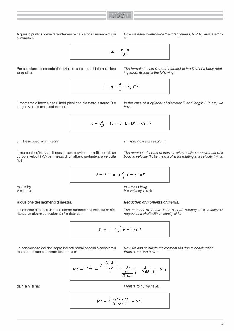
A questo punto si deve fare intervenire nei calcoli il numero di girial minuto n.
Per calcolare il momento d’inerzia J di corpi rotanti intorno al loroasse si ha:
Il momento d’inerzia per cilindri pieni con diametro esterno D elunghezza L in cm si ottiene con:
v = Peso specifico in g/cm3
Il momento d’inerzia di masse con movimento rettilineo di uncorpo a velocità (V) per mezzo di un albero ruotante alla velocitàn, è
m = in kgV = in m/s
Riduzione dei momenti d’inerzia.Il momento d’inerzia J2 su un albero ruotante alla velocità n2 rife-rito ad un albero con velocità n1 è dato da:
La conoscenza dei dati sopra indicati rende possibile calcolare ilmomento d’accelerazione Ma da 0 a n1
da n1 a n2 si ha:
Now we have to introduce the rotary speed, R.P.M., indicated byn.
The formula to calculate the moment of inertia J of a body rotat-ing about its axis is the following:
In the case of a cylinder of diameter D and length L in cm, wehave:
v = specific weight in g/cm3
The moment of inertia of masses with rectilinear movement of abody at velocity (V) by means of shaft rotating at a velocity (n), is:
m = mass in kgV = velocity in m/s
Reduction of moments of inertia.The moment of inertia J2 on a shaft rotating at a velocity n2
respect to a shaft with a velocity n1 is:
Now we can calculate the moment Ma due to acceleration.From 0 to n1 we have:
From n1 to n2, we have:

6
Riassumendo:
il cui valore non deve mai essere superiore al valore Mi indicatonelle tabelle tecniche per ogni grandezza
Calcolo del tempo di accelerazione o decelerazione:
Da 0 a n1 si ha:
da n1 a n2 si ha:
Mi = Momento inseribile innesto o freno (a catalogo)Mic = Momento dovuto al carico (da calcolo)Mi – Mic per accelerazioneMi + Mic per decelerazione
Se l’innesto avviene a vuoto o con un carico trascurabile si ha:
Essendo a volte difficile conoscere esattamente tutti questi dati,è sufficiente determinare la coppia «Mt» con la seguente formu-la:
dove: Mt = Momento del carico in (Nm)P = Potenza motore in kWn = Numero giri/min. dell’albero innesto o freno
N.B.: Il valore dato da questa formula è un valore nominale eperciò insufficiente a stabilire la grandezza dell’innesto o delfreno. La nostra esperienza ci ha portato a stabilire dei valori dimaggiorazione, in modo da consentire un margine di sicurezza.
Mt di sicurezza = Mt nominale per K.
K = Coefficente di maggiorazione, che varia come segue:
In conclusion:
which value must never exceed the value of Mi indicated in tech-nical tables.
Calculation of acceleration or deceleration time:
From 0 to n1, we have:
From n1 to n2, we have:
Mi = Engageable coupling or braking moment (per catalog)Mic = Moment due to the load (as calculated)Mi – Mic due to accelerationMi + Mic due to deceleration
If coupling occurs under little or no load, we have:
Sometimes exact values are difficult to obtain, so you can usethis formula in order to determinate the «Mt»:
where: Mt = Moment due to the load (Nm)P = Motor power in kWn = R.P.M. of coupling or brake shaft
NOTE: This formula gives a nominal value, which is insufficientto establish the coupling or brake size. Based on our experience,we have made these values higher to provide an adequate safe-ty factor.
Mt with safety factor = Mt nominal value times K.
The different values of the safety factor K are shown in the fol-lowing table.

7
Il valore del momento Mt dato dalla formula:
non deve essere superiore al momento inseribile «Mi» dato dallafrizione o dal freno a catalogo.
The moment’s value Mt calculated from the formula:
must not be higher than engageable moment, «Mi», given by theclutch or brake, as shown in the catalogue.
Azionamento - Driver Max innesti/h - Max couplings/h «K»
Motore elettricoElectric motor
1 ÷ 40 1,25 ÷ 1,540 ÷ 200 1,5 ÷ 1,75
200 ÷ 600 1,75 ÷ 2600 ÷ 1800 2 ÷ 2,5
1800 ÷ 3600 2,5 ÷ 33600 ÷ 6000 3 ÷ 3,5
Motore idraulicoHydraulic motor
1 ÷ 40 1,75 ÷ 240 ÷ 200 2 ÷ 2,5
200 ÷ 600 2,5 ÷ 3600 ÷ 1800 3 ÷ 3,5
Motore dieselDiesel engine
1 ÷ 40 3 ÷ 3,2540 ÷ 200 3,25 ÷ 3,5
200 ÷ 600 3,5 ÷ 4Comando compressore a pistoni
Piston compressor control – 4 ÷ 5
TABELLA OLIIPer giunti limitatori di coppia, frizioni e freni oleodinamici sonoconsigliati i seguenti:
DIMENSIONI FORI E CHIAVETTE - Secondo DIN 6885 foglio 2
All’ordine specificare sempre:– Dimensione foro o albero– Dimensione cava per chiavetta
OIL TABLEThe recommended oils for torque-limiting joints and hydraulicclutches and brakes are as follows:
HOLE AND KEY DIMENSIONS - According DIN 6885 Sheet 2
With all orders, please specify:– Hole or shaft dimensions– Key-slot dimensions
D >10 >12 >17 >22 >30 >38 >44 >50 >58 >65 >75 >85 >95 >110 >130 >150÷12 ÷17 ÷22 ÷30 ÷38 ÷44 ÷50 ÷58 ÷65 ÷75 ÷85 ÷95 ÷110 ÷130 ÷150 ÷170
B 4 5 6 8 10 12 14 16 18 20 22 25 28 32 36 40H 4 5 6 7 8 8 9 10 11 12 14 14 16 18 20 22
T1 3 3,8 4,4 5,4 6 6 6,5 7,5 8 8 10 10 11 13 13,7 14
T2 1,1 1,3 1,7 1,7 2,1 2,1 2,6 2,6 3,1 4,1 4,1 4,1 5,1 5,2 6,5 8,2
AGIP OTE 46 3,9 °E a 50° CESSO TERESSO 46 3,9 °E a 50° CSHELL TURBO 46 3,9 °E a 50° CCASTROL PERFECTO T46 3,8 °E a 50° CMOBIL DTE Medium 3,8 °E a 50° C
8
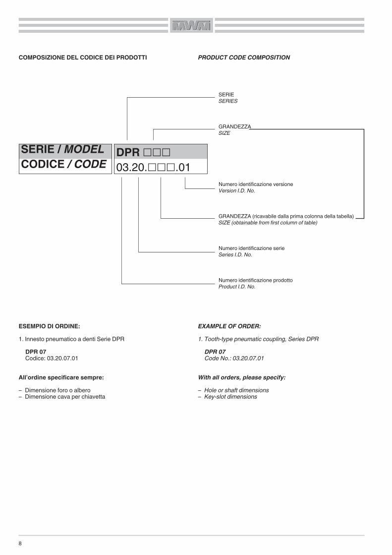
COMPOSIZIONE DEL CODICE DEI PRODOTTI
ESEMPIO DI ORDINE:1. Innesto pneumatico a denti Serie DPRDPR 07Codice: 03.20.07.01
All’ordine specificare sempre:– Dimensione foro o albero– Dimensione cava per chiavetta
PRODUCT CODE COMPOSITION
EXAMPLE OF ORDER:1. Tooth-type pneumatic coupling, Series DPRDPR 07Code No.: 03.20.07.01
With all orders, please specify:– Hole or shaft dimensions– Key-slot dimensions
SERIE / MODELCODICE / CODE
DPR ���03.20.���.01
SERIESERIES
GRANDEZZASIZE
Numero identificazione versioneVersion I.D. No.
GRANDEZZA (ricavabile dalla prima colonna della tabella)SIZE (obtainable from first column of table)
Numero identificazione serieSeries I.D. No.
Numero identificazione prodottoProduct I.D. No.

9
020202GIUNTI LIMITATORI DI COPPIA
TORQUE-LIMITING COUPLINGS
10
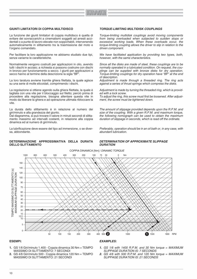
GIUNTI LIMITATORI DI COPPIA MULTIDISCOLa funzione dei giunti limitatori di coppia multidisco è quella dievitare dei sovraccarichi a cinematismi soggetti ad arresti acci-dentali o a punte di lavoro elevate non sopportabili, intervenendoautomaticamente in slittamento tra la trasmissione del moto el’organo comandato.Per facilitare la loro applicazione ne abbiamo studiato due tipi,senza variarne le caratteristiche.Normalmente vengono costruiti per applicazioni in olio, avendotutti i dischi in acciaio; a richiesta si possono costruire con dischiin bronzo per funzionamento a secco. I giunti per applicazioni asecco hanno al termine della descrizione la sigla “BF”.La loro taratura avviene tramite ghiera filettata, la quale agiscesu una serie di molle elicoidali, comprimendo i dischi.La regolazione si ottiene agendo sulla ghiera filettata, la quale ètagliata con una vite per il bloccaggio sul filetto; perciò prima diprocedere alla regolazione, bisogna allentare questa vite inmodo da liberare la ghiera e ad operazione ultimata ribloccare lavite.La durata dello slittamento è in relazione al numero deigiri/minuto e alla grandezza del giunto.Dal diagramma, si può trovare il valore in minuti secondi di slitta-mento massimo ad intervalli costanti, in relazione alla coppiadinamica ed al numero di giri/minuto.La lubrificazione deve essere del tipo ad immersione, o se diver-sa, abbondante.
DETERMINAZIONE APPROSSIMATIVA DELLA DURATADELLO SLITTAMENTO
ESEMPI:1. GS 1/6 Giri/minuto 1.400 - Coppia dinamica 30 Nm = TEMPO
MASSIMO DI SLITTAMENTO: 7 SECONDI2. GS 4/6 Giri/minuto 500 - Coppia dinamica 120 Nm = TEMPO
MASSIMO DI SLITTAMENTO: 21 SECONDI
TORQUE-LIMITING MULTIDISK COUPLINGSTorque-limiting multidisk couplings avoid moving componentsfrom being overloaded when subjected to sudden stops orexcessive working loads. When these overloads occur, thetorque-limiting coupling allows the driver to slip in relation to thedriven component.We have facilitated application by providing two types, both,however, with the same characteristics.Since all the disks are made of steel, these couplings are to benormally operated in a lubricated condition. On request, the cou-plings can be supplied with bronze disks for dry operation.Torque-limiting couplings for dry operation have “BF” at the endof description.Adjustment is made through a threaded ring. The ring actsagainst a series of thrust springs which compress the disks.Adjustment is made by turning the threaded ring, which is provid-ed with a lock screw.To adjust the ring, this screw must first be loosened. After adjust-ment, the screw must be tightened down.
The amount of slippage provided depends upon the R.P.M. andsize of the coupling. With a given R.P.M. and maximum torque,the following nomograph can be used to obtain the maximumduration of slippage in seconds, which is read off the ordinate.
Preferably, operation should be in an oil bath or, in any case, withabundant lubrication.
DETERMINATION OF APPROXIMATE SLIPPAGEDURATION
EXAMPLES:1. GS 1/6 with 1400 R.P.M. and 30 Nm torque = MAXIMUM
SLIPPAGE DURATION IS: 7 SECONDS2. GS 4/6 with 500 R.P.M. and 120 Nm torque = MAXIMUM
SLIPPAGE DURATION IS: 21 SECONDS
160
140
120
105
90
75
60
50
40
30
25
20
1512,5
10
5
0
1000 800 600 500 400 300 200 100 75 50 0 Nm
50 100 150 200 300 400 500 1000 1500 1800 RPM
TEMP
OMA
SSIM
ODI
SLITT
AMEN
TO[s]
MAXIMU
MSL
IPPA
GEDU
RATIO
N
COPPIA DINAMICA [Nm] / DINAMIC TORQUE
��

11
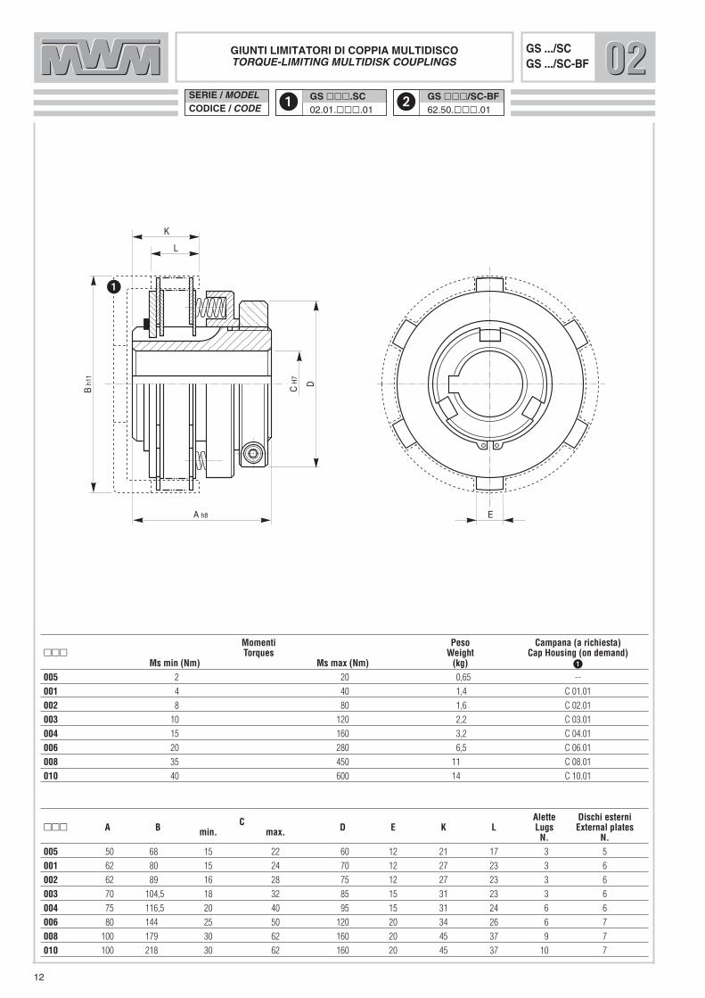
DISTINTA PARTICOLARI1. MOZZO CENTRALE2. GHIERA DI REGOLAZIONE3. MOLLA ELICOIDALE4. ANELLO DI SPINTA5. PIATTELLO DI TESTA6. DISCO ESTERNO7. DISCO INTERNO8. VITE DI BLOCCAGGIO GHIERA9. ANELLO DI SICUREZZA
10. CAMPANA (A RICHIESTA)
GS/SCGS/SC
PARTS LIST1. CENTRAL HUB2. ADJUSTMENT RING3. SPRING4. THRUST RING5. HEAD PLATE6. OUTER DISK7. INNER DISK8. RING LOCK SCREW9. SAFETY RING
10. CUP HOUSING (ON DEMAND)
GS/SC GS/SC-BFESEMPI DI MONTAGGIO EXAMPLES OF MOUNTING
10 9 5 6 7 3 4 2 1
8
GS/SC-BF ASECCO - DRY APPLICATIONGS/SC-BF
��SERIE / MODELCODICE / CODE
GS ���.SC02.01.���.01
GS ���/SC-BF62.50.���.01
GIUNTI LIMITATORI DI COPPIA MULTIDISCOTORQUE-LIMITING MULTIDISK COUPLINGS
GS .../SCGS .../SC-BF 020202
C Alette Dischi esterni��� A B min. max. D E K L Lugs External plates
N. N.005 50 68 15 22 60 12 21 17 3 5
001 62 80 15 24 70 12 27 23 3 6
002 62 89 16 28 75 12 27 23 3 6
003 70 104,5 18 32 85 15 31 23 3 6
004 75 116,5 20 40 95 15 31 24 6 6
006 80 144 25 50 120 20 34 26 6 7
008 100 179 30 62 160 20 45 37 9 7
010 100 218 30 62 160 20 45 37 10 7
Momenti Peso Campana (a richiesta)��� Torques Weight Cap Housing (on demand)
Ms min (Nm) Ms max (Nm) (kg) �
005 2 20 0,65 --
001 4 40 1,4 C 01.01
002 8 80 1,6 C 02.01
003 10 120 2,2 C 03.01
004 15 160 3,2 C 04.01
006 20 280 6,5 C 06.01
008 35 450 11 C 08.01
010 40 600 14 C 10.01
12
L
A h8
CH
7
Bh1
1
D
K
E

13
DISTINTA PARTICOLARI1. CAMPANA2. GHIERA DI REGOLAZIONE3. ANELLO DI SPINTA4. MOLLA ELICOIDALE5. VITE DI BLOCCAGGIO GHIERA6. DISCO INTERNO7. DISCO ESTERNO8. ANELLO DI SICUREZZA9. MOZZO (A RICHIESTA)
GS/SMGS/SM
PARTS LIST1. CUP HOUSING2. ADJUSTMENT RING3. THRUST RING4. SPRING5. RING LOCK SCREW6. INNER DISK7. OUTER DISK8. SAFETY RING9. HUB (ON DEMAND)
GS/SMESEMPI DI MONTAGGIO EXAMPLES OF MOUNTING
1 2 3 4 6 7 8 9
5
GS/SM-BF ASECCO - DRY APPLICATIONGS/SM-BF
GS/SM-BF

SERIE / MODELCODICE / CODE
E
A h8
CH
7
Bh1
1
D
H
GF h8
GIUNTI LIMITATORI DI COPPIA MULTIDISCOTORQUE-LIMITING MULTIDISK COUPLINGS
GS .../SMGS .../SM-BF
C Alette Dischi interni��� A B min. max. D E F G H Lugs Internal plates
N. N.05/5 50 68 15 24 54 37 28 5 6 3 5
1/6 70 82 16 28 70 43 38 5 9 3 6
2/6 70 93 16 28 75 47 40 5 9 3 6
3/6 85 108 18 35 89 55 48 8 9 3 6
4/6 85 118 20 48 104 66 48 6 12 3 6
6/6 100 145 25 58 120 86 58 6 14 3 7
8/7 120 180 30 62 130 100 70 7 12 6 7
10/7 140 220 30 72 140 100 84 8 12 6 7
Momenti Peso Mozzo (a richiesta)��� Torques Weight Hub (on demand)
Ms min (Nm) Ms max (Nm) (kg) �
05/5 2 20 0,9 MF 05
1/6 4 40 1,5 MF 1
2/6 8 80 1,9 MF 2
3/6 10 120 3 MF 3
4/6 15 160 4,2 MF 4
6/6 20 280 6,3 MF 6
8/7 35 450 12 MF 8/10
10/7 40 600 18 MF 8/10
020202
14
�� GS ���/SM02.02.���.01
GS ���/SM-BF62.60.���.01
15
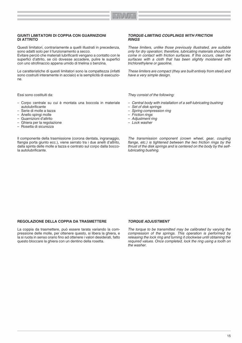
GIUNTI LIMITATORI DI COPPIA CON GUARNIZIONIDI ATTRITOQuesti limitatori, contrariamente a quelli illustrati in precedenza,sono adatti solo per il funzionamento a secco.Evitare perciò che materiali lubrificanti vengano a contatto con lesuperfici d’attrito, se ciò dovesse accadere, pulire le superficicon uno strofinaccio appena umido di trielina o benzina.Le caratteristiche di questi limitatori sono la compattezza (infattisono costruiti interamente in acciaio) e la semplicità di esecuzio-ne.
Essi sono costituiti da:– Corpo centrale su cui è montata una boccola in materiale
autolubrificante– Serie di molle a tazza– Anello spingi molle– Guarnizioni d’attrito– Ghiera per la regolazione– Rosetta di sicurezza
Il componente della trasmissione (corona dentata, ingranaggio,flangia porta giunto ecc.), viene serrato tra i due anelli d’attrito,dalla spinta delle molle a tazza e centrato sul corpo dalla bocco-la autolubrificante.
REGOLAZIONE DELLA COPPIA DA TRASMETTERELa coppia da trasmettere, può essere tarata variando la com-pressione delle molle, per ottenere questo, si libera la ghiera, ela si ruota in senso orario fino ad ottenere i valori desiderati, fattoquesto bloccare la ghiera con un dentino della rosetta.
TORQUE-LIMITING COUPLINGS WITH FRICTIONRINGSThese limiters, unlike those previously illustrated, are suitableonly for dry operation; therefore, lubricating materials should notcome in contact with friction surfaces. If this occurs, clean thesurfaces with a cloth that has been slightly moistened withtrichlorethylene or gasoline.These limiters are compact (they are built entirely from steel) andhave a very simple design.
They consist of the following:– Central body with installation of a self-lubricating bushing– Set of disk springs– Spring compression ring– Friction rings– Adjustment ring– Lock washer
The transmission component (crown wheel, gear, couplingflange, etc.) is tightened between the two friction rings by thethrust of the disk springs and is centered on the body by the self-lubricating bushing.
TORQUE ADJUSTMENTThe torque to be transmitted may be calibrated by varying thecompression of the springs. This operation is performed byreleasing the lock ring and turning it clockwise until obtaining therequired values. Once completed, lock the ring using a tooth onthe washer.

DISTINTA PARTICOLARI1. MOZZO2. GUARNIZIONE D’ATTRITO3. ANELLO DI SPINTA4. MOLLA A TAZZA5. ROSETTA DI SICUREZZA6. GHIERA DI REGOLAZIONE7. BRONZINA8. FLANGIA PER GIUNTO9. GIUNTO ELASTICO
GS/CDGS/CD
PARTS LIST1. HUB2. FRICTION RING3. THRUST RING4. DISK SPRING5. LOCKWASHER6. ADJUSTMENT RING7. BUSHING8. COUPLING FLANGE9. FLEXIBLE COUPLING
GS/CDESEMPI DI MONTAGGIO EXAMPLES OF MOUNTING
GS/GE
1 2 7 3 4
5
2
6
GS/GEGS/GE1 2
7 3 4
5
2
6
9 8
16
17
Dh8
F
A h8
CH
7
Bh1
1
G
H
E
J K
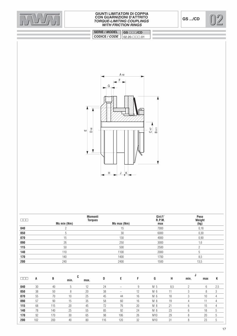
GIUNTI LIMITATORI DI COPPIACON GUARNIZIONI D’ATTRITOTORQUE-LIMITING COUPLINGS
WITH FRICTION RINGSGS .../CD
C J��� A B min. max. D E F G H min. max K
040 30 40 5 12 24 – 9 M 5 8,5 2 6 2,5
050 38 50 8 20 38 – 12 M 6 11 3 8 3
070 55 70 10 25 45 44 16 M 6 18 3 10 4
090 57 90 15 35 58 60 16 M 8 19 4 11 4
115 68 115 20 45 72 76 20 M 8 21 6 15 4
140 78 140 25 55 85 92 24 M 8 23 6 18 5
170 92 170 30 65 98 106 26 M10 29 8 20 5
200 102 200 40 80 116 120 32 M10 31 8 23 5
Momenti Giri/1’ Peso��� Torques R.P.M. Weight
Ms min (Nm) Ms max (Nm) max (kg)040 2 15 7000 0,18
050 5 30 6000 0,30
070 15 130 4000 0,90
090 26 250 3000 1,6
115 50 500 2500 2
140 110 1100 2000 5
170 140 1400 1700 8,5
200 240 2400 1500 13,5
020202SERIE / MODELCODICE / CODE
GS ���/CD02.20.���.01
X
Y
A h8
EH
7
Fh1
1
H
B
J
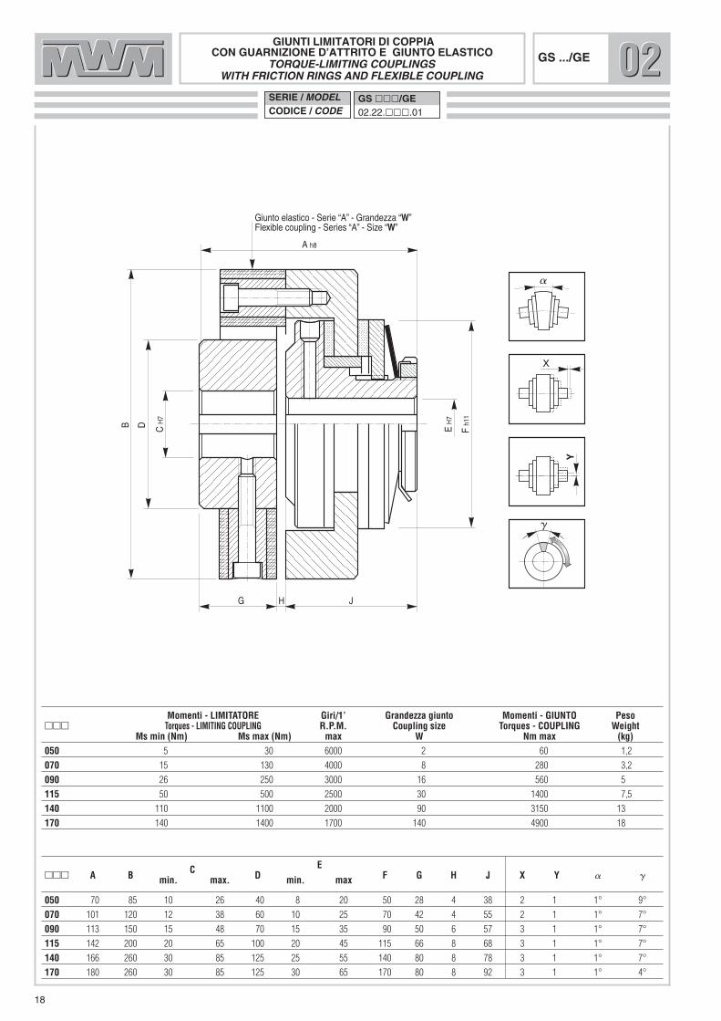
Giunto elastico - Serie “A” - Grandezza “W”Flexible coupling - Series “A” - Size “W”
CH
7
D
G
GIUNTI LIMITATORI DI COPPIACON GUARNIZIONE D’ATTRITO E GIUNTO ELASTICO
TORQUE-LIMITING COUPLINGSWITH FRICTION RINGS AND FLEXIBLE COUPLING
GS .../GE
C E��� A B min. max. D min. max F G H J X Y � �
050 70 85 10 26 40 8 20 50 28 4 38 2 1 1° 9°
070 101 120 12 38 60 10 25 70 42 4 55 2 1 1° 7°
090 113 150 15 48 70 15 35 90 50 6 57 3 1 1° 7°
115 142 200 20 65 100 20 45 115 66 8 68 3 1 1° 7°
140 166 260 30 85 125 25 55 140 80 8 78 3 1 1° 7°
170 180 260 30 85 125 30 65 170 80 8 92 3 1 1° 4°
Momenti - LIMITATORE Giri/1’ Grandezza giunto Momenti - GIUNTO Peso��� Torques - LIMITING COUPLING R.P.M. Coupling size Torques - COUPLING Weight
Ms min (Nm) Ms max (Nm) max W Nm max (kg)050 5 30 6000 2 60 1,2
070 15 130 4000 8 280 3,2
090 26 250 3000 16 560 5
115 50 500 2500 30 1400 7,5
140 110 1100 2000 90 3150 13
170 140 1400 1700 140 4900 18
020202SERIE / MODELCODICE / CODE
GS ���/GE02.22.���.01
18

19
LIMITATORI DI COPPIA MECCANICI A DENTIA SCORRIMENTO ASSIALE
La funzione di questi limitatori, è quella di proteggere ed even-tualmente far arrestare la trasmissione, in presenza di carichieccessivi o blocchi accidentali che possano provocare rotture omalfunzionamenti nella trasmissione stessa.Essi sono costruiti con materiali selezionati, e le parti soggette aslittamento, (dentature), sono trattate in modo tale da poter sop-portare, senza danneggiarsi, slittamenti di breve durata.La trasmissione del moto è garantita dalla spinta assiale eserci-tata da una serie di molle elicoidali che, opportunamente carica-te o scaricate provocano l’aumento o la diminuzione della coppia(vedi regolazione della coppia).
UTILIZZO DEL MICROINTERRUTTORESul corpo esterno del limitatore, è ricavata una gola per l’allog-giamento dell’astina di un microinterruttore, che permette la tara-tura del microinterruttore stesso, cioè la possibilità, avvicinando-lo o allontanandolo, di variarne la sensibilità di intervento,partendo da un minimo accenno di slittamento (le dentature ten-dono ad allontanarsi), fino ad un completo slittamento del limita-tore.Ove si renda necessario, si può collegare il microinterruttore conun freno di sicurezza, si potrà avere così l’arresto immediatodella trasmissione, qualora subentrino carichi pericolosi.
MECHANICAL TOOTH-TYPE TORQUE LIMITERS WITHAXIAL SLIPPAGE
These limiters are designed to protect and even stop the trans-mission when excessive loads or accidental jams occur whichmay lead to break down or malfunctions in the transmissionitself.They are built with carefully selected materials and the compo-nents subject to slippage (toothing) are treated to withstand briefslippage without damage.The motion is transmitted by the axial thrust provided by a set ofhelical springs which, properly compressed or released,increase or decrease the torque (see torque adjustment).
MICROSWITCH SETTINGA slot on the external casing of the limiter houses themicroswitch rod. This rod is used to calibrate the microswitch,i.e. it is possible, by moving the rod in or out, to vary the operat-ing sensitivity, from minimum slippage (the teeth tend to moveaway from each other) to complete limiter slippage.
If necessary, the microswitch can be connected with a safetybrake. This means that the transmission can be immediatelystopped when dangerous loads occur.
20
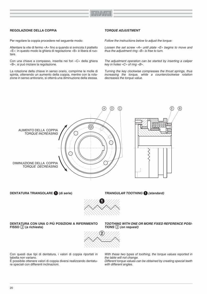
REGOLAZIONE DELLA COPPIA
Per regolare la coppia procedere nel seguente modo:Allentare la vite di fermo «A» fino a quando si svincola il piattello«E»: in questo modo la ghiera di regolazione «B» è libera di ruo-tare.Con una chiave a compasso, inserita nei fori «C» della ghiera«B», si può iniziare la regolazione.La rotazione della chiave in senso orario, comprime le molle dispinta, ottenendo un aumento della coppia, mentre con la rota-zione in senso antiorario, si otterrà una diminuzione della stessa.
DENTATURA TRIANGOLARE � (di serie)
DENTATURA CON UNA O PIÙ POSIZIONI A RIFERIMENTOFISSO � (a richiesta)
Con questi due tipi di dentatura, i valori di coppia riportati intabella non variano.È possibile ottenere valori di coppia diversi realizzando dentatu-re speciali con differenti inclinazioni.
TORQUE ADJUSTMENT
Follow the instructions below to adjust the torque:Loosen the set screw «A» until plate «E» begins to move andthus the adjustment ring «B» is free to turn.
The adjustment operation can be started by inserting a caliperkey in holes «C» of ring «B».Turning the key clockwise compresses the thrust springs, thusincreasing the torque, while a counterclockwise rotationdecreases the torque value.
TRIANGULAR TOOTHING � (standard)
TOOTHINGWITH ONE OR MORE FIXED REFERENCE POSI-TIONS � (on request)
With these two types of toothing, the torque values reported inthe table will not change.Different torque values can be obtained by creating special teethwith different angles.
A D C E B
1
2
AUMENTO DELLA COPPIATORQUE INCREASING
DIMINUIZIONE DELLA COPPIATORQUE DECREASING
21
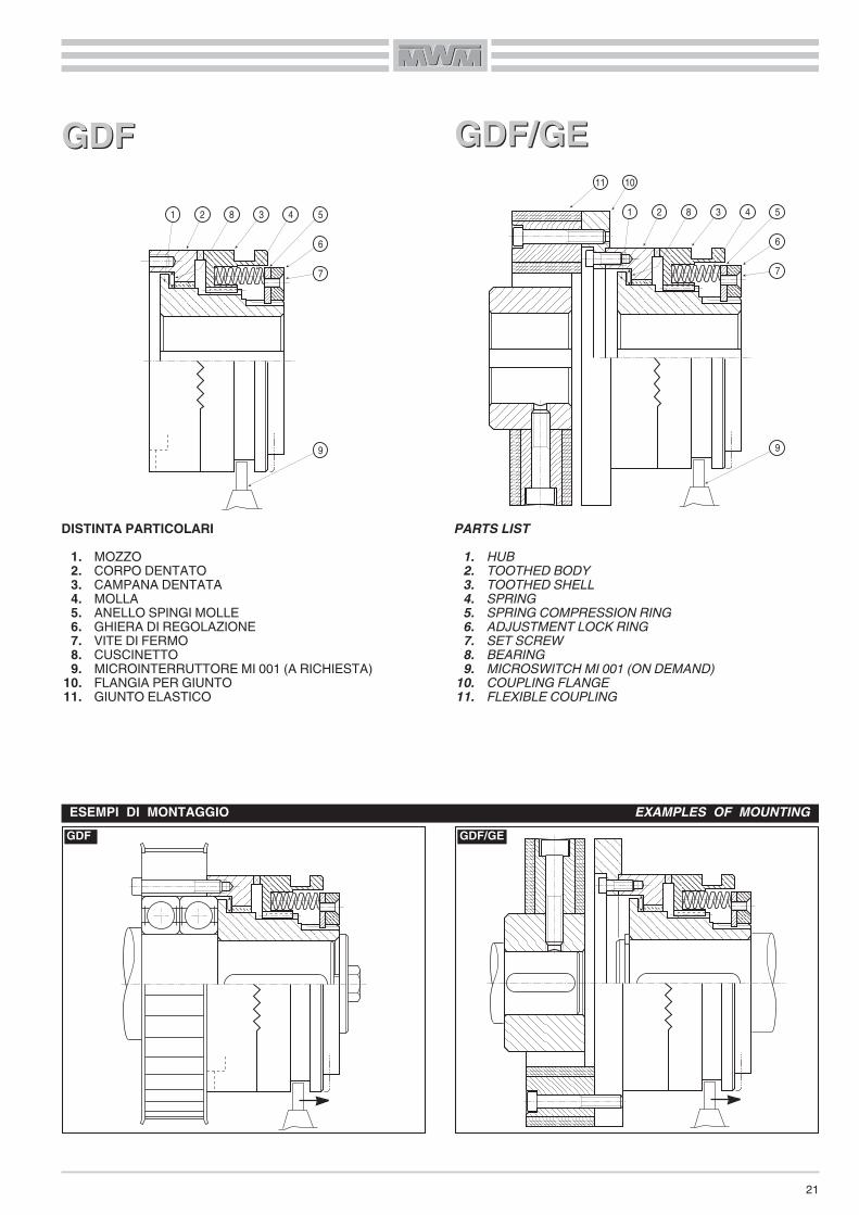
DISTINTA PARTICOLARI1. MOZZO2. CORPO DENTATO3. CAMPANA DENTATA4. MOLLA5. ANELLO SPINGI MOLLE6. GHIERA DI REGOLAZIONE7. VITE DI FERMO8. CUSCINETTO9. MICROINTERRUTTORE MI 001 (A RICHIESTA)
10. FLANGIA PER GIUNTO11. GIUNTO ELASTICO
GDFGDF
PARTS LIST1. HUB2. TOOTHED BODY3. TOOTHED SHELL4. SPRING5. SPRING COMPRESSION RING6. ADJUSTMENT LOCK RING7. SET SCREW8. BEARING9. MICROSWITCH MI 001 (ON DEMAND)
10. COUPLING FLANGE11. FLEXIBLE COUPLING
GDFESEMPI DI MONTAGGIO EXAMPLES OF MOUNTING
GDF/GE
1 2 8 3 4 5
6
7
9
1 2 8 3 4 5
6
7
9
11 10
GDF/GEGDF/GE
22
E FH
8
N P
CH
7
D
Bh1
1
K J H
A h8
L Q
G x n°
M
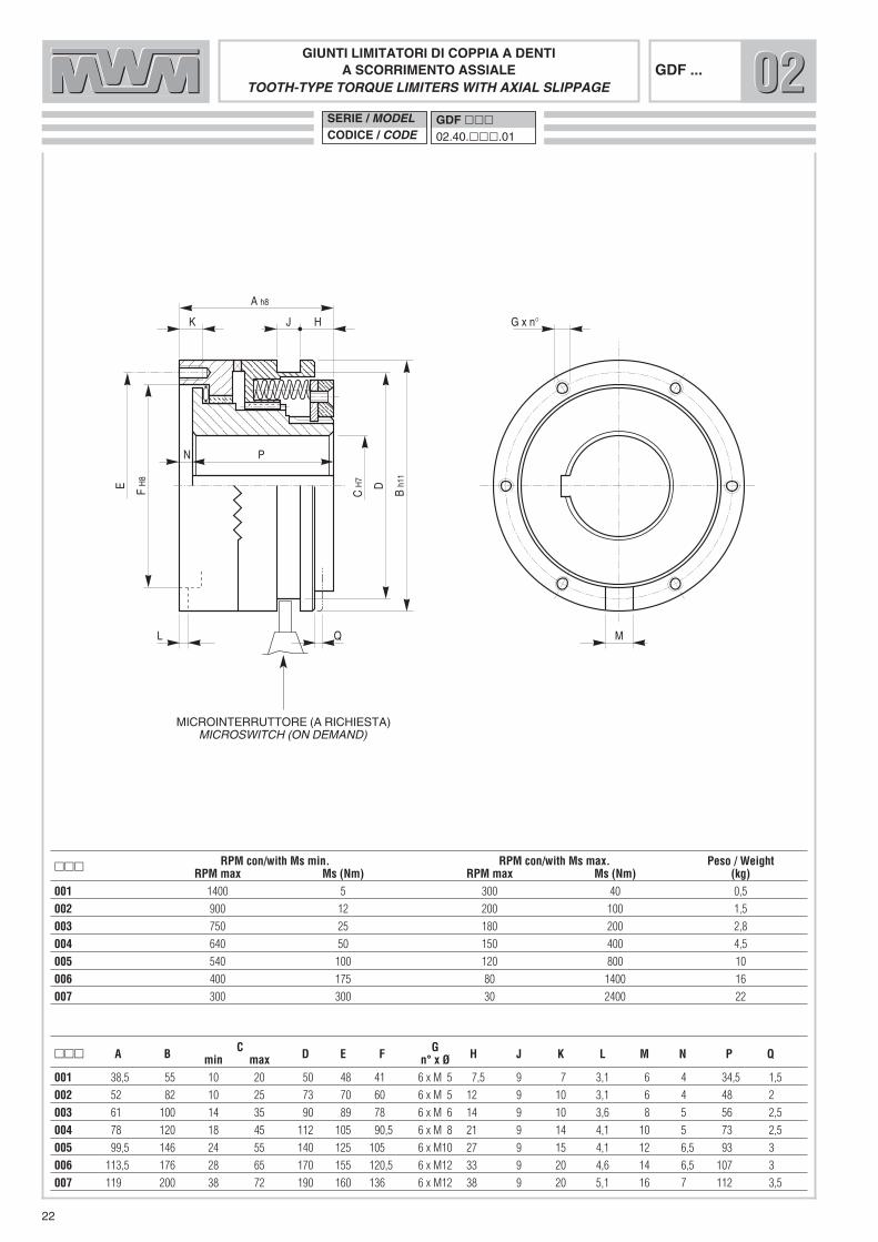
GIUNTI LIMITATORI DI COPPIA A DENTIA SCORRIMENTO ASSIALE
TOOTH-TYPE TORQUE LIMITERS WITH AXIAL SLIPPAGEGDF ...
��� A B C D E F G H J K L M N P Qmin max n° x Ø001 38,5 55 10 20 50 48 41 6 x M 5 7,5 9 7 3,1 6 4 34,5 1,5
002 52 82 10 25 73 70 60 6 x M 5 12 9 10 3,1 6 4 48 2
003 61 100 14 35 90 89 78 6 x M 6 14 9 10 3,6 8 5 56 2,5
004 78 120 18 45 112 105 90,5 6 x M 8 21 9 14 4,1 10 5 73 2,5
005 99,5 146 24 55 140 125 105 6 x M10 27 9 15 4,1 12 6,5 93 3
006 113,5 176 28 65 170 155 120,5 6 x M12 33 9 20 4,6 14 6,5 107 3
007 119 200 38 72 190 160 136 6 x M12 38 9 20 5,1 16 7 112 3,5
��� RPM con/with Ms min. RPM con/with Ms max. Peso / WeightRPM max Ms (Nm) RPM max Ms (Nm) (kg)
001 1400 5 300 40 0,5
002 900 12 200 100 1,5
003 750 25 180 200 2,8
004 640 50 150 400 4,5
005 540 100 120 800 10
006 400 175 80 1400 16
007 300 300 30 2400 22
020202SERIE / MODELCODICE / CODE
GDF ���02.40.���.01
MICROINTERRUTTORE (A RICHIESTA)MICROSWITCH (ON DEMAND)

23
X
Y
G F
P
CH
7
D
Bh1
1
J H
Q
Giunto elastico - Serie “A” - Grandezza “W”Flexible coupling - Series “A” - Size “W”
LKM
A
EH
7
GIUNTI LIMITATORI DI COPPIAA DENTI CON GIUNTO ELASTICO
TOOTH-TYPE TORQUE LIMITERS WITH FLEXIBLE COUPLINGGDF .../GE
��� A B C D E F G H J K L M P Q X Y α γmin. max min. max001 70,5 55 10 20 50 10 26 40 85 7,5 9 4 38,5 28 34,5 1,5 2 1 1° 9°
002 113 82 10 25 73 12 38 60 120 12 9 4 67 42 48 2 2 1 1° 7°
003 122 100 14 35 90 12 38 60 122 14 9 4 76 42 56 2,5 2 1 1° 4°
004 154 120 18 45 112 15 48 70 150 21 9 6 98 50 73 2,5 3 1 1° 4°
005 198 146 24 55 140 20 65 100 200 27 9 8 124 66 93 3 3 1 1° 7°
006 213 176 28 65 170 20 65 100 205 33 9 4 143 66 107 3 2 1 1° 4°
006 234 200 38 72 190 30 85 125 260 38 9 8 146 80 112 3,5 3 1 1° 7°
RPM con / with Ms min RPM con / with Ms max. Grandezza giunto Momenti - Giunto Peso��� Coupling size Torques - Coupling Weight
RPM max Ms Nm) RPM max. Ms (Nm) W Nm max (kg)001 1400 5 300 40 2 60 1
002 900 12 200 100 8 280 3,1
003 750 25 180 200 12 360 5
004 640 50 150 400 22 750 8,7
005 540 100 120 800 30 1400 19,3
006 400 175 80 1400 80 2100 26,9
007 300 300 30 2400 90 3150 40,5
020202SERIE / MODELCODICE / CODE
GDF ���/GE02.42.���.01
MICROINTERRUTTORE (A RICHIESTA)MICROSWITCH (ON DEMAND)
GDFRGDFR
GDFRESEMPI DI MONTAGGIO EXAMPLES OF MOUNTING
GDFM
1 9 8 2 8 3 4 5 6
7
10
24
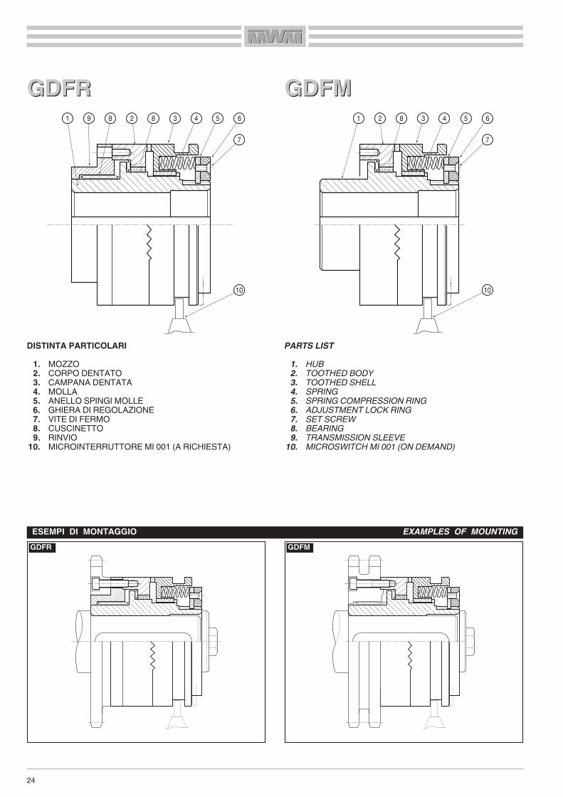
DISTINTA PARTICOLARI1. MOZZO2. CORPO DENTATO3. CAMPANA DENTATA4. MOLLA5. ANELLO SPINGI MOLLE6. GHIERA DI REGOLAZIONE7. VITE DI FERMO8. CUSCINETTO9. RINVIO
10. MICROINTERRUTTORE MI 001 (A RICHIESTA)
PARTS LIST1. HUB2. TOOTHED BODY3. TOOTHED SHELL4. SPRING5. SPRING COMPRESSION RING6. ADJUSTMENT LOCK RING7. SET SCREW8. BEARING9. TRANSMISSION SLEEVE
10. MICROSWITCH MI 001 (ON DEMAND)
GDFMGDFM1 2 8 3 4 5 6
7
10

25
GIUNTI LIMITATORI DI COPPIA A DENTIA SCORRIMENTO ASSIALE
TOOTH-TYPE TORQUE LIMITERS WITH AXIAL SLIPPAGEGDFR ...
SERIE / MODELCODICE / CODE
GDFR ���02.44.���.01
Sf7
U
T D
Bh1
1
K J H
A h8
Q
G x n°
CH
7
R
E
��� A B C D E G H J K Q R S T Umin max n° x Ø001 51 55 10 20 50 48 6 x M 5 7,5 9 11 1,5 8 38 21 15
002 70 82 10 25 73 70 6 x M 5 12 9 16 2 10 50 26 20
003 78 100 14 35 90 89 6 x M 6 14 9 15 2,5 12 60 36 25
004 96 120 18 45 112 105 6 x M 8 21 9 18 2,5 12 80 46 30
005 124 146 24 55 140 125 6 x M10 27 9 23,5 3 16 100 56 30
006 140 176 28 65 170 155 6 x M12 33 9 25,5 3 18 120 66 30
007 150 200 38 72 190 160 6 x M12 38 9 30 3,5 20 130 76 25
��� RPM con/with Ms min. RPM con/with Ms max. Peso / WeightRPM max Ms (Nm) RPM max Ms (Nm) (kg)
001 1400 5 300 40 0,7
002 900 12 200 100 2
003 750 25 180 200 3
004 640 50 150 400 6
005 540 100 120 800 12
006 400 175 80 1400 20
007 300 300 30 2400 26
020202
MICROINTERRUTTORE (A RICHIESTA)MICROSWITCH (ON DEMAND)

GIUNTI LIMITATORI DI COPPIA A DENTIA SCORRIMENTO ASSIALE
TOOTH-TYPE TORQUE LIMITERS WITH AXIAL SLIPPAGEGDFM ...
SERIE / MODELCODICE / CODE
GDFM ���02.46.���.01
26
MICROINTERRUTTORE (A RICHIESTA)MICROSWITCH (ON DEMAND)
020202
��� A B C D E F G H J K L M N Q R S T Umin max n° x Ø001 66 55 10 20 50 48 41 6 x M 5 7,5 9 7 3,1 6 4 1,5 27,5 28 21 25
002 85 82 10 25 73 70 60 6 x M 5 12 9 10 3,1 6 4 2 33 38 26 35
003 100 100 14 35 90 89 78 6 x M 6 14 9 10 3,6 8 5 2,5 39 52 36 45
004 125 120 18 45 112 105 90,5 6 x M 8 21 9 14 4,1 10 5 2,5 47 65 46 60
005 152 146 24 55 140 125 105 6 x M10 27 9 15 4,1 12 6,5 3 52,5 78 56 60
006 171 176 28 65 170 155 120,5 6 x M12 33 9 20 4,6 14 6,5 3 57,5 90 66 60
007 183 200 38 72 190 160 136 6 x M12 38 9 20 5,1 16 7 3,5 64 108 76 55
��� RPM con/with Ms min. RPM con/with Ms max. Peso / WeightRPM max Ms (Nm) RPM max Ms (Nm) (kg)
001 1400 5 300 40 0,6
002 900 12 200 100 1,8
003 750 25 180 200 3,2
004 640 50 150 400 6
005 540 100 120 800 12
006 400 175 80 1400 19
007 300 300 30 2400 25
Sf7
N U
T D
Bh1
1
K J H
A h8
L Q
G x n°
M
CH
7
FH
8
R
E
27
LIMITATORI DI COPPIA PNEUMATICI A DENTI CONSEGNALE ELETTRICO
Questi limitatori sono particolarmente adatti per quelle trasmis-sioni dove, in fase di avvio, necessita la massima potenza. Que-sto lo si può ottenere con una variazione di pressione: massimaall’inizio, poi raggiunto il regime voluto, la si può diminuire, finoad arrivare alla coppia di lavoro richiesta.Essi sono costruiti con materiali selezionati, e le parti soggette aslittamento (dentature), sono trattate in modo tale da poter sop-portare senza danneggiarsi, slittamenti di breve durata.La trasmissione del moto, avviene solo in presenza di una pres-sione di alimentazione, che agendo sul pistone lo fa avanzareprovocando così l’innesto delle dentature.Una serie di molle elicoidali contrapposte alla pressione di ali-mentazione, fanno in modo che, qualora si verifichi un calo o lamancanza totale di pressione, avvenga lo svincolo completo trale dentature di trascinamento, rendendo così indipendenti leparti della trasmissione.Perciò questi tipi di limitatori, all’occorrenza possono essereusati tranquillamente anche come innesti a denti.
• ALIMENTAZIONEPer il buon funzionamento del limitatore, e per una maggioresicurezza della trasmissione, è necessario che la pressione dialimentazione sia mantenuta ad un valore costante; si consigliaperciò l’utilizzo di un polmone che possa compensare eventualivariazioni di pressione.La valvola di comando deve essere montata il più vicino possibi-le al foro di alimentazione posto sul cilindro, ed inoltre dovràavere lo scarico rapido, cosicchè qualora subentrassero carichipericolosi, l’intervento del micro interruttore faccia in modo chequesta scarichi repentinamente la pressione, provocando così losvincolo completo dei componenti la trasmissione, salvaguar-dandone il buon funzionamento.
PNEUMATIC TOOTH-TYPE TORQUE LIMITERSWITH ELEC-TRIC SIGNAL
These limiters are particularly suitable for those transmissionswhich require maximum power during start-up. This powerrequirement can be met by varying the pressure; maximum atthe start and, once the required speed is obtained, it can bedecreased, until reaching the needed operating torque.They are built with carefully selected materials and the compo-nents subject to slippage (toothing) are treated to withstand briefslippage without damage.The motion is transmitted only with supply pressure, which byadvancing the piston engages the toothing.
A set of helical springs which counter the supply pressure areused to completely release the entrainment toothing during areduction or complete loss of pressure, and thus transmissioncomponents are made independent.
Therefore, if necessary, these types of limiters may also be usedas tooth-type couplings.
• SUPPLYTo ensure that the limiter operates correctly and to enhancetransmission safety, the supply pressure must always be con-stant; therefore, an accumulation tank should be used to com-pensate for any pressure changes.
The control valve must be mounted as close as possible to thesupply hole located on the cylinder and it must also be equippedwith a blow-off device so that if dangerous loads occur, themicroswitch will trip and immediately discharge the pressure,thus completely releasing the transmission components, andprotecting the unit.
28
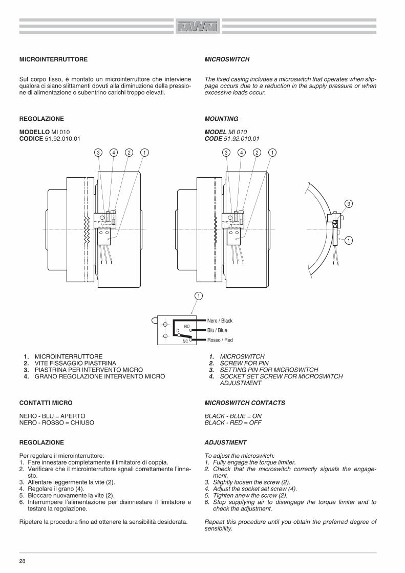
MICROINTERRUTTORE
Sul corpo fisso, è montato un microinterruttore che intervienequalora ci siano slittamenti dovuti alla diminuzione della pressio-ne di alimentazione o subentrino carichi troppo elevati.
REGOLAZIONEMODELLO MI 010CODICE 51.92.010.01
1. MICROINTERRUTTORE2. VITE FISSAGGIO PIASTRINA3. PIASTRINA PER INTERVENTO MICRO4. GRANO REGOLAZIONE INTERVENTO MICRO
CONTATTI MICRONERO - BLU = APERTONERO - ROSSO = CHIUSO
REGOLAZIONEPer regolare il microinterruttore:1. Fare innestare completamente il limitatore di coppia.2. Verificare che il microinterruttore sgnali correttamente l’inne-
sto.3. Allentare leggermente la vite (2).4. Regolare il grano (4).5. Bloccare nuovamente la vite (2).6. Interrompere l’alimentazione per disinnestare il limitatore e
testare la regolazione.Ripetere la procedura fino ad ottenere la sensibilità desiderata.
MICROSWITCH
The fixed casing includes a microswitch that operates when slip-page occurs due to a reduction in the supply pressure or whenexcessive loads occur.
MOUNTINGMODEL MI 010CODE 51.92.010.01
1. MICROSWITCH2. SCREW FOR PIN3. SETTING PIN FOR MICROSWITCH4. SOCKET SET SCREW FOR MICROSWITCH
ADJUSTMENT
MICROSWITCH CONTACTSBLACK - BLUE = ONBLACK - RED = OFF
ADJUSTMENTTo adjust the microswitch:1. Fully engage the torque limiter.2. Check that the microswitch correctly signals the engage-
ment.3. Slightly loosen the screw (2).4. Adjust the socket set screw (4).5. Tighten anew the screw (2).6. Stop supplying air to disengage the torque limiter and to
check the adjustment.Repeat this procedure until you obtain the preferred degree ofsensibility.
Nero / Black
Blu / Blue
Rosso / Red
NOC
NC
3 4 2 1 3 4 2 1
1
1
3
29
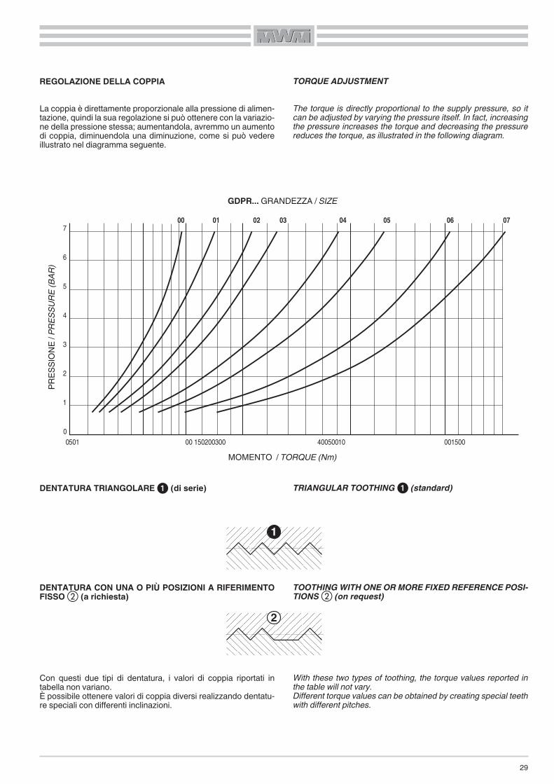
REGOLAZIONE DELLA COPPIA
La coppia è direttamente proporzionale alla pressione di alimen-tazione, quindi la sua regolazione si può ottenere con la variazio-ne della pressione stessa; aumentandola, avremmo un aumentodi coppia, diminuendola una diminuzione, come si può vedereillustrato nel diagramma seguente.
DENTATURA TRIANGOLARE � (di serie)
DENTATURA CON UNA O PIÙ POSIZIONI A RIFERIMENTOFISSO � (a richiesta)
Con questi due tipi di dentatura, i valori di coppia riportati intabella non variano.È possibile ottenere valori di coppia diversi realizzando dentatu-re speciali con differenti inclinazioni.
TORQUE ADJUSTMENT
The torque is directly proportional to the supply pressure, so itcan be adjusted by varying the pressure itself. In fact, increasingthe pressure increases the torque and decreasing the pressurereduces the torque, as illustrated in the following diagram.
TRIANGULAR TOOTHING � (standard)
TOOTHINGWITH ONE OR MORE FIXED REFERENCE POSI-TIONS � (on request)
With these two types of toothing, the torque values reported inthe table will not vary.Different torque values can be obtained by creating special teethwith different pitches.
1
2
3
4
5
6
7
00501 00 150200300 40050010 00 1500
00 01 02 03 04 05 06 07
1
2
PRES
SION
E/P
RESS
URE(BAR
)
GDPR... GRANDEZZA / SIZE
MOMENTO / TORQUE (Nm)

DISTINTA PARTICOLARI1. MOZZO CENTRALE2. CILINDRO3. PISTONE4. ANELLO DENTATO5. CANNOTTO DI RINVIO6. ANELLO PREMI MOLLE7. GUARNIZIONE DI TENUTA8. CUSCINETTO PISTONE9. CUSCINETTO RINVIO
10. CUSCINETTO MOZZO11. MOLLA12. MICROINTERRUTTORE13. FLANGIA PER GIUNTO ELASTICO14. GIUNTO ELASTICO
GDPRGDPR
PARTS LIST1. CENTRAL HUB2. CYLINDER3. PISTON4. TOOTHED RING5. TRANSMISSION SLEEVE6. SPRING COMPRESSION RING7. SEAL RING8. PISTON BEARING9. SLEEVE BEARING
10. HUB BEARING11. SPRING12. MICROSWITCH13. COUPLING FLANGE14. FLEXIBLE COUPLING
GDPRESEMPI DI MONTAGGIO EXAMPLES OF MOUNTING
GDPG
5 9 6 11 4 3 12 8 2
7
10
1
30
GDPGGDPG5 9
6 11 4 3 12 8 2
7
10
1
1314
31
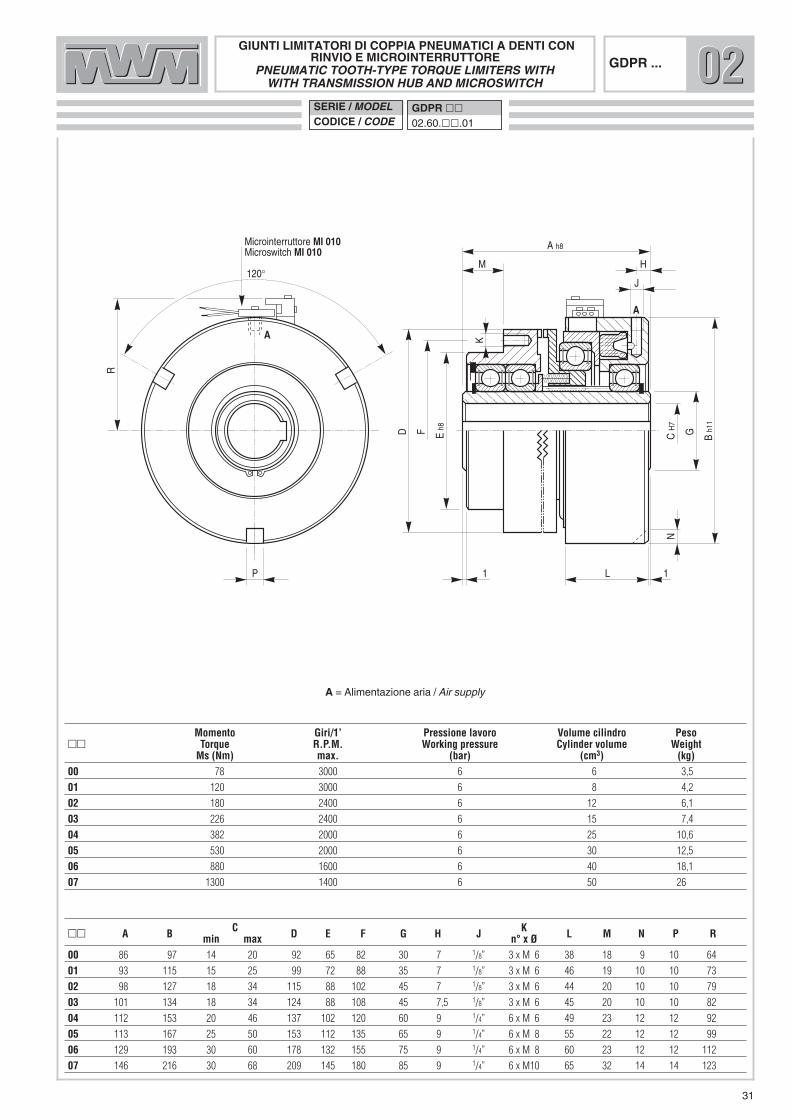
A = Alimentazione aria / Air supply
D Eh8
M
A h8
CH
7
Bh1
1
H
J
1 L 1
F G
N
R
P
K
120°
A
A
Microinterruttore MI 010Microswitch MI 010
GIUNTI LIMITATORI DI COPPIA PNEUMATICI A DENTI CONRINVIO E MICROINTERRUTTORE
PNEUMATIC TOOTH-TYPE TORQUE LIMITERS WITHWITH TRANSMISSION HUB AND MICROSWITCH
GDPR ...
�� A B C D E F G H J K L M N P Rmin max n° x Ø00 86 97 14 20 92 65 82 30 7 1/8” 3 x M 6 38 18 9 10 64
01 93 115 15 25 99 72 88 35 7 1/8” 3 x M 6 46 19 10 10 73
02 98 127 18 34 115 88 102 45 7 1/8” 3 x M 6 44 20 10 10 79
03 101 134 18 34 124 88 108 45 7,5 1/8” 3 x M 6 45 20 10 10 82
04 112 153 20 46 137 102 120 60 9 1/4” 6 x M 6 49 23 12 12 92
05 113 167 25 50 153 112 135 65 9 1/4” 6 x M 8 55 22 12 12 99
06 129 193 30 60 178 132 155 75 9 1/4” 6 x M 8 60 23 12 12 112
07 146 216 30 68 209 145 180 85 9 1/4” 6 x M10 65 32 14 14 123
Momento Giri/1’ Pressione lavoro Volume cilindro Peso�� Torque R.P.M. Working pressure Cylinder volume Weight
Ms (Nm) max. (bar) (cm3) (kg)00 78 3000 6 6 3,5
01 120 3000 6 8 4,2
02 180 2400 6 12 6,1
03 226 2400 6 15 7,4
04 382 2000 6 25 10,6
05 530 2000 6 30 12,5
06 880 1600 6 40 18,1
07 1300 1400 6 50 26
020202SERIE / MODELCODICE / CODE
GDPR ��02.60.��.01

D E F CH
7
B
H
J
K 1
G
P
A
R
x Q - 3 a 120°
N h8ML
A
Microinterruttore MI 010Microswitch MI 010
X
Y
Giunto elastico - Serie “A” - Grandezza “W”Flexible coupling - Series “A” - Size “W”
GIUNTI LIMITATORI DI COPPIA PNEUMATICI A DENTICON GIUNTO ELASTICO E MICROINTERRUTTOREPNEUMATIC TOOTH-TYPE TORQUE LIMITERS WITH
FLEXIBLE COUPLING AND MICROSWITCHGDPG...
�� A B C D E F G H J K L M N PxQ R X Y α γγmin. max min. max00 132 97 14 20 120 60 12 38 30 7 1/8” 38 42 4 86 9x10 64 2 1 1° 7°
01 139 115 15 25 120 60 12 38 35 7 1/8” 46 42 4 93 10x10 73 2 1 1° 7°
02 144 127 18 34 122 60 12 38 45 7 1/8” 44 42 4 98 10x10 79 2 1 1° 4°
03 157 134 18 34 150 70 15 48 45 7,5 1/8” 45 50 6 101 10x10 82 2 1 1° 4°
04 168 153 20 46 150 70 15 48 60 9 1/4” 49 50 6 112 12x12 92 3 1 1° 4°
05 174 167 25 50 170 85 15 55 65 9 1/4” 55 55 6 113 12x12 99 3 1 1° 4°
06 203 193 30 60 200 100 20 65 75 9 1/4” 60 66 8 129 12x12 112 3 1 1° 4°
07 234 216 30 68 260 125 30 85 85 9 1/4” 65 80 8 146 14x14 123 3 1 1° 7°
Momento - LIMITATORE Giri/1’ Pressione lavoro Volume cilindro Grandezza giunto Peso�� Torque - LIMITING COUPLING R.P.M. Working pressure Cylinder volume Coupling size Weight
Ms (Nm) max. (bar) (cm3) W (kg)00 78 3000 6 6 8 6,2
01 120 3000 6 8 8 6,4
02 180 2400 6 12 12 8,3
03 226 2400 6 15 16 11,3
04 382 2000 6 25 22 14,7
05 530 2000 6 30 28 18,3
06 880 1600 6 40 50 27,1
07 1300 1400 6 50 90 45,0
020202SERIE / MODELCODICE / CODE
GDPG ��02.62.��.01
32
A = Alimentazione aria / Air supply
33
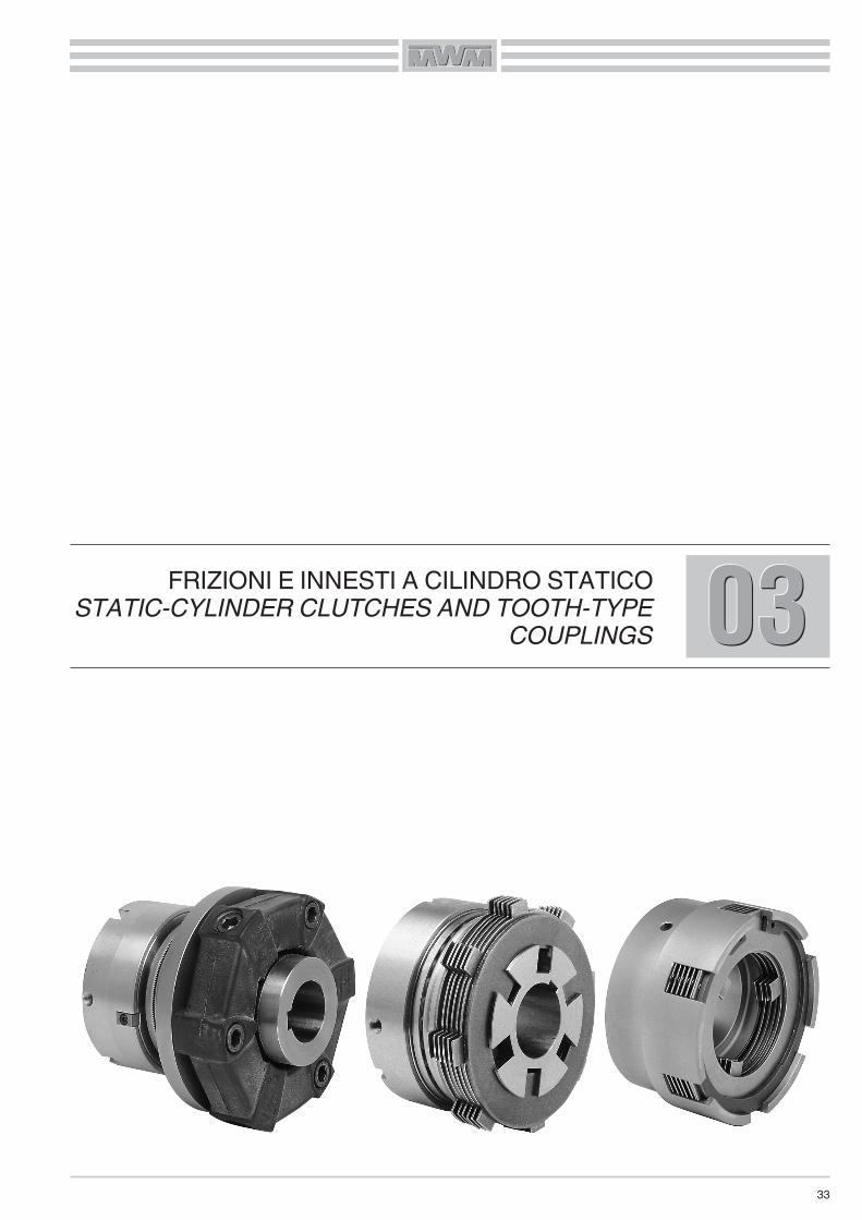
030303FRIZIONI E INNESTI A CILINDRO STATICOSTATIC-CYLINDER CLUTCHES AND TOOTH-TYPE
COUPLINGS

34
FRIZIONI PNEUMATICHE / OLEODINAMICHE MULTIDISCOA CILINDRO STATICO
Queste frizioni hanno trovato largo impiego in tutto il settoremeccanico industriale, per le loro ottime caratteristiche tecniche,costruttive e di funzionamento.Sono composte da un mozzo centrale, un pacco dischi, duecuscinetti assiali e da un pistone con un cilindro di lavoro fisso.L’adduzione dell’olio/aria in pressione avviene attraverso il foro«A» sul diametro esterno del cilindro, soluzione che permette dievitare complicati percorsi e dà la possibilità di montare più fri-zioni sullo stesso albero.Il cilindro di lavoro, non essendo in rotazione, ha il vantaggio dinon creare forze centrifughe nell’olio in pressione, permettendoinnesti e soprattutto disinnesti più rapidi, così migliorando la fre-quenza degli interventi.Una serie di molle elicoidali genera una forza di pressione assia-le tale da consentire il ritorno rapido del pistone in posizione diriposo, influendo con valori minimi sulla spinta di lavoro.Il pistone fisso trasmette la sua forza di spinta ai dischi in rotazio-ne attraverso un robusto cuscinetto assiale.La corsa del pistone e le molle elicoidali permettono il recuperodell’usura dei dischi, escludendo la necessità di registrazione.Queste frizioni, sono costruite per applicazioni in olio o in pre-senza di nebbia d’olio avendo due cuscinetti assiali e tutti i dischiin acciaio.Solo in quelle applicazioni dove il numero di giri/minuto non èmolto elevato e la frequenza degli innesti è molto bassa si pos-sono impiegare per funzionamento a secco.L’impiego di queste frizioni è ideale in unità operatrici con circuitioleodinamici, essendo costruite per funzionare ad olio in pres-sione.Vengono realizzate anche per funzionare ad aria compressa;quest’ultima costruzione varia dalla precedente perchè monta, alposto delle due guarnizioni in gomma speciale, un’unica guarni-zione, consentendo la tenuta dell’aria compressa nel cilindro.Per evitare qualsiasi trascinamento in posizione di riposo, arichiesta montiamo tra i dischi interni, speciali molle staccadisco.Questa soluzione è particolarmente adatta dove l’applicazionedella frizione è verticale, o in presenza di cinematismi molto sen-sibili, oppure per ottenere una maggiore precisione nel disinne-sto.
PNEUMATIC / HYDRAULIC STATIC-CYLINDER MULTI-DISKCLUTCH
The excellent technical, construction and operating characteris-tics of these clutches have resulted in a wide number of applica-tions through the manufacturing industry. Their simple design includes a central hub, a disk pack, two axialbearings and a fixed cylinder with a working piston.Oil/air under pressure enters through external port «A», a solu-tion which permits the elimination of complicated channeling andallows several clutches to be mounted on the same shaft.
Since the cylinder does not rotate, no centrifugal forces aredeveloped in the pressurized oil, thus permitting more rapid cou-pling and, in particular, uncoupling, which improves interventionfrequency.A series of high-spring-rate thrust springs returns the pistonrapidly to its neutral position and have little effect on the workingthrust.The fixed piston transmits its thrust to the rotating disks througha rugged axial bearing.The stroke of the piston and thrust springs permit disk-wear take-up, thus eliminating the need for adjustment.Since these clutches have all-steel disks and axial bearings,they must operate in an oil bath or under oil-mist conditions.The only situation where they could be operated dry is when theR.P.M. are not very high and the intervention frequency is verylow.
Since these clutches are designed for operation with oil underpressure, they are ideal for applications on equipment usinghydraulics. On request, these clutches are also available foroperation with compressed air.The compressed-air versions have a special single seal insteadof the two rubber seals used in the oil clutches, which allowscompressed-air sealing in the cylinder.
In order to avoid any dragging in the neutral position, we cansupply, on request, units provided with special disk-separatingsprings. This feature is particularly useful where the clutch ismounted vertically or in the presence of very sensitive movingparts or when greater uncoupling precision is required.

35
MONTAGGIO
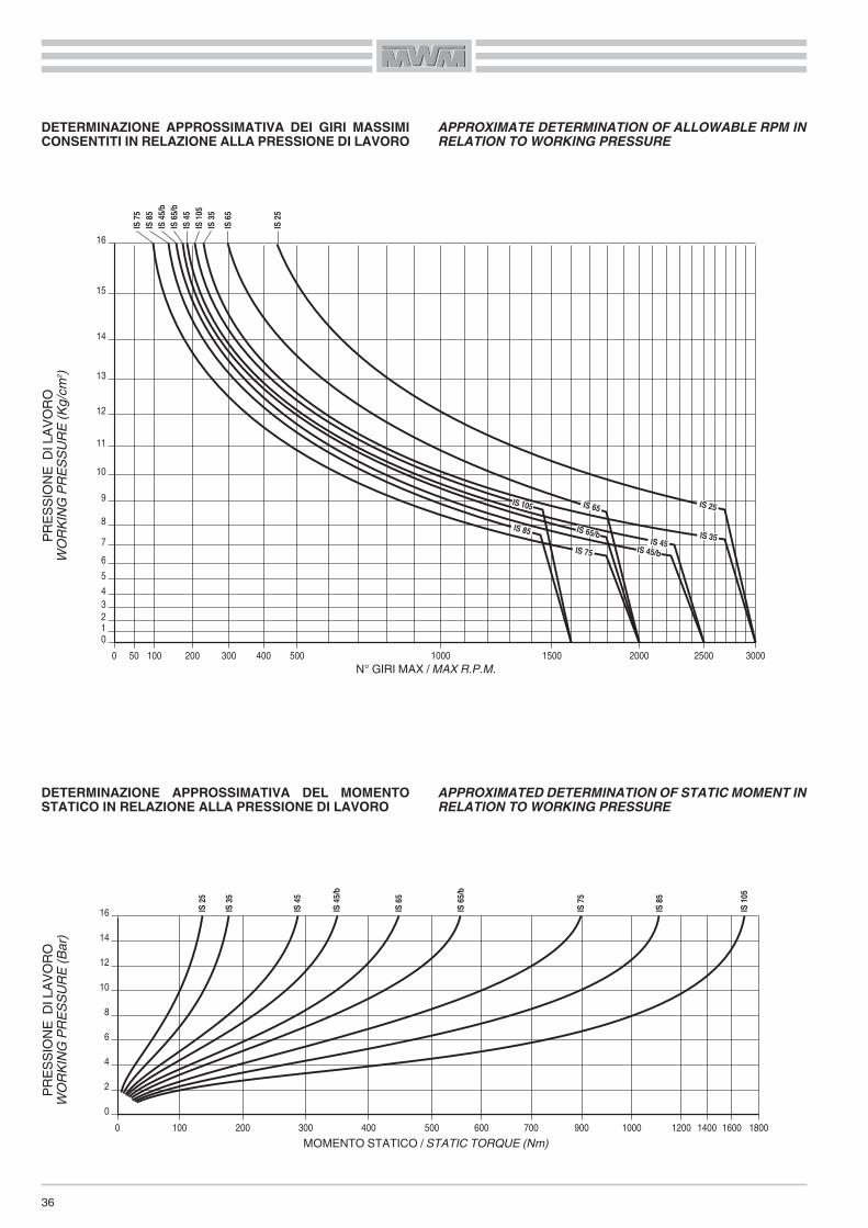
Per il montaggio seguire le istruzioni e gli esempi da noi proposti.Il cilindro di lavoro deve essere ancorato in modo non rigido tra-mite una staffa messa in corrispondenza di una delle tre fresatu-re a 120° ricavate sullo stesso; la staffa si aggancerà alla fresa-tura più comoda, in relazione al foro di adduzione dell’olio,tenendo bene presente che il cilindro di lavoro dovrà avere unleggero giuoco sia assiale che radiale.Per l’adduzione dell’olio/aria si deve usare un tubo flessibile;questo serve ad evitare quelle tensioni assiali e radiali della stes-sa importanza delle precedenti, le quali andrebbero a disturbareil buon funzionamento dei cuscinetti, causando delle rotture ed ilcattivo funzionamento della frizione.Le tubazioni per l’adduzione dell’olio/aria non devono presentarecurve troppo strette, strozzature da riduzioni, oppure percorsilunghi; simili ostacoli rallenterebbero l’afflusso e il deflusso del-l’olio/aria danneggiando la frizione.La lubrificazione ha un ruolo importante e a volte può determina-re la durata della frizione, è bene utilizzare una forte lubrificazio-ne del tipo a pioggia, o meglio del tipo forzato.Per il tipo di olio da impiegare, consigliamo di consultare il Forni-tore, tenendo presente che è importante usare olii con viscositànon superiore ai 5°E/50°C.Il valore delle coppie riportato dalle tabelle è da considerare talesolo alla pressione d’esercizio da noi consigliata. Variando lapressione d’esercizio si ottengono coppie più alte o più basse inrapporto alla variazione della pressione, ESSENDO DIRETTA-MENTE PROPORZIONALI.Variando la pressione d’esercizio varia il numero di giri/minutomassimo ammissibile della frizione, vedi diagramma alla paginaseguente,
MOUNTING
When mounting, please follow our instructions and examples.The work cylinder must be anchored, but not fixed rigidly,between a bracket located at one of the three 120° milled spotson the work cylinder. The bracket is to be hooked onto the mostconvenient milled spot, in relation to the oil filler hole, makingsure the work cylinder has some axial and radial play.
Use a flexible oil/air line, so as to avoid creating axial and radialtensions which, if excessive, could upset the proper workingcharacteristics of the bearings and thus cause poor operationand eventual clutch failure.
The oil/air line should not be too long and should not have anytight bends, kinks or any alternation that could impede free flow,the lack of which could lead to clutch damage. If the clutch is to have a maximum service life, it needs to be welllubricated, such as by splashing or, better yet, by using forcedlubrication.We suggest the supplier be contacted for recommendationsregarding the type of oil to use. In any case, the oil viscosityshould not exceed 5°E/50°C.The torque values given in the graph are only valid for our rec-ommended working pressures. Pressure changes will producePROPORTIONAL increases or decreases in torque: i.e., torqueis proportional to working pressure.
As the working pressure changes, the maximum allowableclutch R.P.M. will change, as shown in the diagram on the nextpage.
36
DETERMINAZIONE APPROSSIMATIVA DEI GIRI MASSIMICONSENTITI IN RELAZIONE ALLA PRESSIONE DI LAVORO
DETERMINAZIONE APPROSSIMATIVA DEL MOMENTOSTATICO IN RELAZIONE ALLA PRESSIONE DI LAVORO
APPROXIMATE DETERMINATION OF ALLOWABLE RPM INRELATION TO WORKING PRESSURE
APPROXIMATED DETERMINATION OF STATIC MOMENT INRELATION TO WORKING PRESSURE
01234
5
6
7
8
9
10
11
12
13
14
15
16
0 50 100 200 300 400 500 1000 1500 2000 2500 3000
IS 75
IS 85
IS 105
IS 65/bIS 45/b
IS 45
IS 65
IS 35
IS 25
IS 75
IS 85
IS 45
/bIS
65/b
IS 45
IS 10
5IS
35IS
65
IS 25
0
0
2
4
6
8
10
12
14
16
100 200 300 400 500 600 700 900 1000 1200 1400 1600 1800
IS75
IS85
IS45
/b
IS65
/b
IS45
IS10
5
IS35
IS65
IS25
01234
5
6
7
8
9
10
11
12
13
14
15
16
0 50 100 200 300 400 500 1000 1500 2000 2500 3000
IS 75
IS 85
IS 105
IS 65/bIS 45/b
IS 45
IS 65
IS 35
IS 25
IS75
IS85
IS45
/bIS
65/b
IS45
IS10
5IS
35IS
65
IS25
0
0
2
4
6
8
10
12
14
16
100 200 300 400 500 600 700 900 1000 1200 1400 1600 1800
IS 75
IS 85
IS 45
/b
IS 65
/b
IS 45
IS 10
5
IS 35
IS 65
IS 25
PRES
SION
E D
I LAV
ORO
WOR
KING
PRES
SURE
(Kg/c
m2)
N° GIRI MAX / MAX R.P.M.
MOMENTO STATICO / STATIC TORQUE (Nm)
PRES
SION
E D
I LAV
ORO
WOR
KING
PRES
SURE
(Bar)

37
ISESEMPI DI MONTAGGIO EXAMPLES OF MOUNTING
IS OLEODINAMICA / HYDRAULICIS8 9 4 13 11 12 2
5
10
14
7
15
6
1
3
PNS/BF PNEUMATICA / PNEUMATICPNS/BF8 9 4 13 2
5
10
14
7
15
6
1
3 11
DISTINTA PARTICOLARI1. MOZZO CENTRALE2. CILINDRO3. PISTONE4. CUSCINETTO PISTONE5. CUSCINETTO MOZZO6. PIATTELLO DI TESTA7. DISCO INTERNO8. DISCO ESTERNO9. PIATTELLO DI SPINTA
10. ROSETTA DI FERMO11. GUARNIZIONE DI TENUTA12. GUARNIZIONE DI TENUTA13. BRONZINA14. ANELLO DI SICUREZZA15. CAMPANA (A RICHIESTA)
PARTS LIST1. CENTRAL HUB2. CYLINDER3. PISTON4. PISTON BEARING5. HUB BEARING6. HEAD PLATE7. INNER DISK8. OUTER DISK9. THRUST PLATE
10. LOCK WASHER11. SEAL RING12. SEAL RING13. BRONZE BUSHING14. SAFETY RING15. CUP HOUSING (ON DEMAND)
PNS/BF

H
A h8
C H
7
F h1
1
E
P
45°
L
K
120°
120°
GN
D
B h1
1
J
A
L
FRIZIONE OLEODINAMICA MULTIDISCO A CILINDRO STATICOHYDRAULIC STATIC-CYLINDER MULTI-DISK CLUTCH
IS ...
Alette��� A B C D E F G H J K L N P Lugsmin max N.025 69 97 16 30 59 40 98 6 1/8” 4 8 12 24 22 6
035 69 108,5 18 36 72 45 108 7 1/8” 4 8 12,5 25 22 8
045 75 116,5 20 40 72 50 112 6 1/8” 5 8 15 29 25 6
045/b 75 120 20 40 72 50 112 6 1/8” 5 8 16 29 25 8
065 90 145 25 46 92 60 130 7 1/8” 6 10 16 33 30 8
065/b 98 145 25 48 92 60 138 7 1/8” 6 10 16 36 32 8
075 105 145 30 44 92 55 158 8 1/4” 7 10 16 41 37 8
085 115 179 30 58 70 75 180 25 1/4” 8 10 20 35 26 9
105 165 218 30 58 70 75 235 24 1/4” 10 12 20 43 34 10
Momenti Pressione lavoro Volume cilindro Peso Dischi esterni Campana��� ������� Torques Working pressure Cylinder volume Weight External plates Cap Housing
a richiesta/on demandMi (Nm) Ms (Nm) (bar) (cm3) (kg) N. �
025 45 80 8 8 2,5 5 C 03.02
035 65 110 8 10 3,2 5 --
045 100 180 8 11 3,8 6 C 04.01
045/b 125 220 8 12 4,2 6 C 05.01
065 160 280 8 19 7 6 C 06.02
065/b 200 350 8 25 7,5 7 C 06.02
075 300 500 8 40 10,5 8 --
085 400 700 8 46 16 5 C 08.01
105 600 1050 8 86 25 6 C 10.01
030303SERIE / MODELCODICE / CODE
IS ���03.01.���.01
38
A = Alimentazione olio / Oil supplyL = Lubrificazione / Lubrication

H
A h8
C H
7
F h1
1
E
P
45°
L
K
120°
120°
GN
D
B h1
1
J
A
L
FRIZIONE PNEUMATICA MULTIDISCO A CILINDRO STATICOPNEUMATIC STATIC-CYLINDER MULTI-DISK CLUTCH
PNS ...
Alette��� A B C D E F G H J K L N P Lugsmin max N.025 69 97 16 30 59 40 98 6 1/8” 4 8 12 24 22 6
045 75 116,5 20 40 72 50 112 6 1/8” 5 8 15 29 25 6
065 90 145 25 46 92 60 130 7 1/8” 6 10 16 33 30 8
Momenti Pressione lavoro Volume cilindro Peso Dischi esterni Campana��� ������� Torques Working pressure Cylinder volume Weight External plates Cap Housing
a richiesta/on demandMi (Nm) Ms (Nm) (bar) (cm3) (kg) N. �
025 30 55 6 8 2,5 5 C 03.02
045 70 130 6 11 3,8 6 C 04.01
065 115 200 6 19 7 6 C 06.02
030303SERIE / MODELCODICE / CODE
PNS ���03.02.���.01
39
A = Alimentazione aria / Air supplyL = Lubrificazione / Lubrication
40
FRIZIONI PNEUMATICHE MULTIDISCOA CILINDRO STATICO
Questo tipo di frizione ha trovato largo impiego in tutto il settoremeccanico industriale, per le sue ottime caratteristiche tecniche,costruttive e di funzionamento.Di semplice costruzione, risulta composta da un mozzo centrale,un pacco dischi, due cuscinetti radiali e un attuatore pneumaticofisso.L’adduzione dell’aria in pressione, attraverso il foro «A» sul dia-metro esterno del cilindro, permette di evitare complicati percor-si di alimentazione e dà la possibilità di montare più frizioni sullostesso albero.Una serie di molle genera una forza assiale tale da consentire ilritorno rapido del pistone in posizione di riposo, influendo convalori minimi sulla spinta di lavoro. Il pistone fisso trasmette la sua forza di spinta ai dischi in rotazio-ne attraverso un robusto cuscinetto radiale.La corsa del pistone e le molle permettono il recupero dell’usuradei dischi, escludendo la necessità di registrazione. Inoltre, ilmontaggio delle molle stesse tra i dischi evita trascinamenti ariposo, consentendo l’installazione della frizione in posizioneverticale, in presenza di cinematismi molto sensibili o laddovesia richiesta una maggiore precisione nel disinnesto.Questa serie di frizioni pneumatiche multidisco è stata progetta-ta per il funzionamento a secco, grazie alla scelta di utilizzaredischi in bronzo/acciaio e cuscinetti con guarnizioni strisciantiche di fatto consentono di operare in assenza di lubrificazione.Le versioni dotate di rinvio (LPR) e di giunto elastico (LPG)estendono ulteriormente la già notevole gamma di applicazionipossibili per queste frizioni.Per il buon funzionamento della frizione è necessario che lapressione di alimentazione sia sempre mantenuta ad un valorecostante: si consiglia perciò l’utilizzo di un polmone, che possacompensare eventuali variazioni di pressione.La valvola di comando, inoltre, deve essere montata il più vicinopossibile al foro di alimentazione posto sul cilindro e dovrà esse-re dotata di scarico rapido per permettere lo svuotamento dell’at-tuatore con il conseguente disinnesto rapido della trasmissione.
MONTAGGIO
Per il montaggio, seguire le istruzioni e gli esempi da noi propo-sti. L’attuatore deve essere ancorato in modo non rigido tramiteuna staffa posta in corrispondenza di una delle tre fresature a120° ricavate sullo stesso; la staffa si aggancerà alla fresaturapiù comoda, in relazione al foro di adduzione dell’aria, tenendoben presente che l’attuatore dovrà avere un leggero giuoco siaassiale che radiale.
PNEUMATIC STATIC-CYLINDER MULTI-DISK CLUTCHES
The excellent technical, construction and operating characteris-tics of this type of clutch have resulted in a wide range of appli-cations in the manufacturing industry.Its simple design includes a center hub, a disk pack, two radialbearings and a fixed cylinder with a working piston
Air under pressure enters through the external bore «A», a solu-tion which permits the elimination of complicated channeling andallows several clutches to be mounted on the same shaft.
A series of disk separating springs, generates sufficient axialpressure to allow the quick return of the piston to its neutral posi-tion, impacting minimally on the working thrust.The fixed piston transmits its power to push the rotating disksthrough a rugged radial bearing.The stroke of the piston and the thrust springs allow disk-weartake-up , thus eliminating the need for adjustment. Furthermore,mounting of the springs between the disks prevents most of thedragging when in the neutral position, allowing the installation ofthe clutch in a vertical position, in the presence of very sensitivekinematic or where greater uncoupling precision is required.This series of pneumatic multi-disk clutches has been engi-neered to run dry, thanks to the choice of using a combination ofbronze/steel disks and sealed bearings that actually allow you towork without lubrication.Variants with transmission sleeve (LPR) and elastic coupling(LPG) further extend the already impressive range of possibleapplications for these clutches.To ensure that the clutch operates correctly, the supply pressuremust always remain constant: so, it would be better to provide foran accumulation tank, in order to compensate any pressurechanges.Also, the control valve must be mounted as close as possible tothe supply bore located on the cylinder and must be equippedwith a blow-off device to discharge the piston and, as a result, toquickly disengage the transmission
MOUNTING
When mounting, please follow our instructions and examples.The working cylinder must be anchored, but not blocked, bymeans of a bracket or pin engaged on one of the three 120°milled spots on the working cylinder itself; this bracket is to behooked onto the most convenient milled spot, in relation to theair supply bore, making sure that the working cylinder has someradial and axial play.

41
DISTINTA PARTICOLARI1. MOZZO CENTRALE2. CILINDRO3. PISTONE4. ANELLO DI SPINTA5. RINVIO6. DISCO ESTERNO7. DISCO INTERNO8. GUARNIZIONE DI TENUTA9. CUSCINETTO MOZZO
10. CUSCINETTO PISTONE11. CUSCINETTO RINVIO12. MOLLA STACCA DISCHI13. SPINA GUIDA MOLLA14. ANELLO DI SICUREZZA ESTERNO15. ANELLO DI SICUREZZA INTERNO16. GIUNTO ELASTICO
LPRLPR
PARTS LIST1. CENTRAL HUB2. CYLINDER3. PISTON4. THRUST RING5. TRANSMISSION HUB6. OUTER DISK7. INNER DISK8. SEAL RING9. HUB BEARING
10. PISTON BEARING11. TRANSMISSION HUB BEARING12. DISK SEPARATING SPRING13. SPRING GUIDE PIN14. OUTER SAFETY RING15. INNER SAFETY RING16. FLEXIBLE COUPLING
LPRESEMPI DI MONTAGGIO EXAMPLES OF MOUNTING
LPG
7 6 4 10 3 8
2
9
1
5 11 13 12
14
15
14
14
15
LPGLPG
2
9
1
14
14
15
11 12 7 6 4 10 3 8516 1315
14

C H
7
B h1
1
F
K
L M
E h8D
A h8
G
H
A
J
120°
A
R max
45°
I
N
P
1
FRIZIONE PNEUMATICA MULTIDISCO CON RINVIOPNEUMATIC MULTIDISK CLUTCH WITH TRANSMISSION HUB
LPR...
��� A B C D E F G H I J x K L M N P Rmin. max. n° x Ø max.
002 100 97 12 22 89 62 30 7 1/8” 80 10 x 9 38 1 3 x M 6 22 11
003 110 115 16 26 104 70 35 7 1/8” 88 10 x 10 46 1 3 x M 6 23,5 11
004 118 127 18 34 116 84 45 7 1/8” 102 10 x 10 44 1 6 x M 6 28 10
006 130 153 20 46 145 105 60 9,5 1/4” 130 12 x 12 49 1,5 6 x M 6 34 10
008 150 167 25 50 179 112 65 9 1/4” 140 12 x 12 55 1 6 x M 8 36 12
010 175 216 30 68 218 145 85 9 1/4” 190 14 x 14 65 1 6 x M10 37 15
Momenti Pressione lavoro Volume cilindro Giri/1’ Peso Dischi interni��� Torques Working pressure Cylinder volume R.P.M. limit Weight Internal plates
Mi (Nm) Ms (Nm) (bar) (cm3) max (kg) N. 002 44 65 6 4 3000 3,2 4
003 75 114 6 6 2800 4,9 4
004 140 210 6 10 2400 6,2 5
006 330 460 6 16 2000 10,5 5
008 590 830 6 30 1800 16,1 6
010 1200 1700 6 50 1400 31 6
SERIE / MODELCODICE / CODE
LPR ���03.06.���.01
42
030303
A = Alimentazione aria / Air supply
X
Y
x J - 3 a 120°
45°Giunto elastico - Serie “A” - Grandezza “W”Flexible coupling - Series “A” - Size “W”
C H
7
B h1
1
F
K
L M
I H7
E
D h
11
N h8
G
H
A
P
A
Q
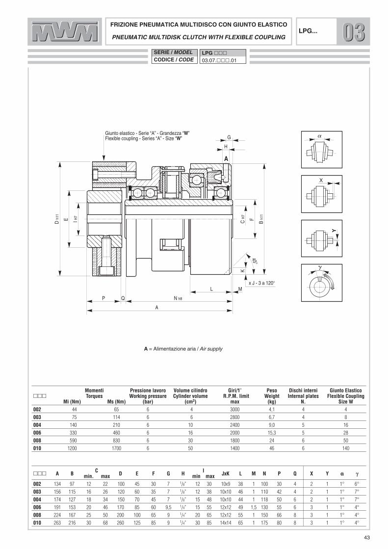
FRIZIONE PNEUMATICA MULTIDISCO CON GIUNTO ELASTICOPNEUMATIC MULTIDISK CLUTCH WITH FLEXIBLE COUPLING
��� A B C D E F G H I JxK L M N P Q X Y α γγmin. max min max002 134 97 12 22 100 45 30 7 1/8” 12 30 10x9 38 1 100 30 4 2 1 1° 6°
003 156 115 16 26 120 60 35 7 1/8” 12 38 10x10 46 1 110 42 4 2 1 1° 7°
004 174 127 18 34 150 70 45 7 1/8” 15 48 10x10 44 1 118 50 6 2 1 1° 7°
006 191 153 20 46 170 85 60 9,5 1/4” 15 55 12x12 49 1,5 130 55 6 3 1 1° 4°
008 224 167 25 50 200 100 65 9 1/4” 20 65 12x12 55 1 150 66 8 3 1 1° 4°
010 263 216 30 68 260 125 85 9 1/4” 30 85 14x14 65 1 175 80 8 3 1 1° 4°
Momenti Pressione lavoro Volume cilindro Giri/1’ Peso Dischi interni Giunto Elastico��� Torques Working pressure Cylinder volume R.P.M. limit Weight Internal plates Flexible Coupling
Mi (Nm) Ms (Nm) (bar) (cm3) max (kg) N. Size W002 44 65 6 4 3000 4,1 4 4
003 75 114 6 6 2800 6,7 4 8
004 140 210 6 10 2400 9,0 5 16
006 330 460 6 16 2000 15,3 5 28
008 590 830 6 30 1800 24 6 50
010 1200 1700 6 50 1400 46 6 140
SERIE / MODELCODICE / CODE
LPG ���03.07.���.01
43
LPG... 030303
A = Alimentazione aria / Air supply
44
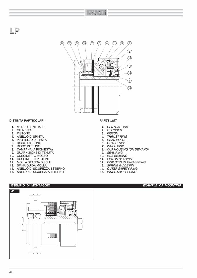
DISTINTA PARTICOLARI1. MOZZO CENTRALE2. CILINDRO3. PISTONE4. ANELLO DI SPINTA5. PIATTELLO DI TESTA6. DISCO ESTERNO7. DISCO INTERNO8. CAMPANA (A RICHIESTA)9. GUARNIZIONE DI TENUTA
10. CUSCINETTO MOZZO11. CUSCINETTO PISTONE12. MOLLA STACCA DISCHI13. SPINA GUIDA MOLLA14. ANELLO DI SICUREZZA ESTERNO15. ANELLO DI SICUREZZA INTERNO
LPLP
PARTS LIST1. CENTRAL HUB2. CYLINDER3. PISTON4. THRUST RING5. HEAD PLATE6. OUTER DISK7. INNER DISK8. CUP HOUSING (ON DEMAND)9. SEAL RING
10. HUB BEARING11. PISTON BEARING12. DISK SEPARATING SPRING13. SPRING GUIDE PIN14. OUTER SAFETY RING15. INNER SAFETY RING
LPESEMPIO DI MONTAGGIO EXAMPLE OF MOUNTING
1
14
14
15
12 5 7 6 4 11 3 98
2
10
13

C H
7
B h1
1
F
K
L M
E
D h
11
N
A h8
G
H
A
J
120°
A
P
45°
FRIZIONE PNEUMATICA MULTIDISCOPNEUMATIC MULTIDISK CLUTCH
��� A B C D E F G H J x K L M N Pmin. max.
002 70 97 12 22 89 49,5 30 7 1/8” 10 x 9 38 1 23 20
003 78 115 16 26 104,5 59 35 7 1/8” 10 x 10 46 1 23 20
004 83 127 18 34 116,5 72 45 7 1/8” 10 x 10 44 1 27 24
006 90 153 20 46 142,5 60 60 9,5 1/4” 12 x 12 49 1,5 28,5 24,5
008 104 167 25 50 179,5 65 65 9 1/4” 12 x 12 55 1 37 30
010 128 216 30 68 218,5 85 85 9 1/4” 14 x 14 65 1 40 33
Momenti Pressione lavoro Volume cilindro Giri/1’ Dischi esterni Peso N° Tagli Campana (a richiesta)��� Torques Working pressure Cylinder volume R.P.M. limit External plates Weight N° Lugs Cup Housing
Mi (Nm) Ms (Nm) (bar) (cm3) max N. (kg) (On demand)002 44 65 6 4 3000 4 2,8 3 C 02.02
003 75 114 6 6 2800 4 4,5 3 C 03.03
004 140 210 6 10 2400 5 5,5 6 C 04.02
006 330 460 6 16 2000 5 9,3 6 C 06.03
008 590 830 6 30 1800 6 12 9 C 08.02
010 1200 1700 6 50 1400 6 25 9 C 10.03
SERIE / MODELCODICE / CODE
LP ���03.08.���.01
45
LP... 030303
A = Alimentazione aria / Air supply

46
FRIZIONI PNEUMATICHE MONODISCOA CILINDRO STATICO
Queste frizioni sono adatte per il solo funzionamento a secco,evitare quindi che la guarnizione d’attrito venga a contatto conmateriali lubrificanti, compromettendo così la coppia di trasmis-sione. Se ciò dovesse accadere, pulire le superfici d’attrito conuno strofinaccio appena umido di trielina o benzina.La caratteristica di queste frizioni è che la coppia è direttamenteproporzionale alla pressione di alimentazione; perciò, al variaredella pressione in più o in meno, si avrà una corrispondentevariazione della coppia.Nel caso in cui la pressione di alimentazione venga a mancare,una serie di molle elicoidali ad essa contrapposte garantisce ilcompleto disinnesto, evitando così trascinamenti.Per il buon funzionamento della frizione, e quindi della trasmis-sione, è necessario che la pressione di alimentazione sia sem-pre mantenuta ad un valore costante; si consiglia, perciò l’utiliz-zo di un polmone che possa compensare eventuali variazioni dipressione.La valvola di comando, deve essere montata il più vicino possi-bile al foro di alimentazione posto sul cilindro, ed inoltre dovràavere lo scarico rapido, per permettere lo svuotamento del pisto-ne e, di conseguenza, il disinnesto veloce della trasmissione.
MONTAGGIO
Per il montaggio, seguire le istruzioni e gli esempi da noi propo-sti. L’attuatore deve essere ancorato in modo non rigido tramiteuna staffa posta in corrispondenza di una delle tre fresature a120° ricavate sullo stesso; la staffa si aggancerà alla fresaturapiù comoda, in relazione al foro di adduzione dell’aria, tenendoben presente che l’attuatore dovrà avere un leggero giuoco siaassiale che radiale.È molto importante, nella fase di montaggio, controllare attenta-mente il traferro (Q) in 3 punti a 120° con uno spessimetro (vedimisura nelle apposite tabelle)
PNEUMATIC SINGLE-PLATE CLUTCHES WITH STATICCYLINDER
These clutches are suitable only for dry operation and thereforethe friction surfaces should not come in contact with lubricatingmaterials, thus affecting the transmission torque. If this occurs,clean them with a cloth slightly moistened with trichlorethylene orgasoline.The main feature of these clutches is that the torque is directlyproportional to the supply pressure; therefore, the torque willvary increasing or decreasing the pressure.
A set of helical springs, to counter the supply pressure, com-pletely disengage the transmission during a total pressure loss,thus avoiding entrainment. To ensure that the coupling, and therefore the transmission,operates correctly, the supply pressure must always remain con-stant; therefore, an accumulation tank should be used to com-pensate for any pressure changes.
The control valve must be mounted as close as possible to thesupply hole located on the cylinder and it must also be equippedwith a blow-off device to discharge the piston and, as a conse-quence, to quickly disengage the transmission.
MOUNTING
When mounting, please follow our instructions and examples.The working cylinder must be anchored, but not blocked, bymeans of a bracket or pin engaged on one of the three 120°milled spots on the working cylinder itself; this bracket is to behooked onto the most convenient milled spot, in relation to theair supply bore, making sure that the working cylinder has someradial and axial play.During the assembly phase, it is very important to check the airgap (Q) at 3 points a 120° with a thickness gauge; it should be asspecified in the relevant tables.
Q
MPGrandezza
SizeTraferro «Q» Air Gap
mm00 0,20 0,3001 0,25 0,3502 0,30 0,4503 0,30 0,4504 0,35 0,5005 0,35 0,5006 0,40 0,6007 0,50 0,70

47
DISTINTA PARTICOLARI1. MOZZO CENTRALE2. CILINDRO3. PISTONE4. ANELLO DI SPINTA5. GUARNIZIONE D’ATTRITO6. ANELLO PREMI MOLLA7. MOLLA8. GUARNIZIONE DI TENUTA9. RINVIO
10. CUSCINETTO PISTONE11. CUSCINETTO MOZZO12. CUSCINETTO RINVIO13. ANELLO DI SICUREZZA ESTERNO14. ANELLO DI SICUREZZA INTERNO15. GIUNTO ELASTICO
PARTS LIST1. CENTRAL HUB2. CYLINDER3. PISTON4. THRUST RING5. FRICTION RING6. SPRING COMPRESSION RING7. SPRING8. SEAL RING9. TRANSMISSION HUB
10. PISTON BEARING11. HUB BEARING12. SLEEVE BEARING13. OUTER SAFETY RING14. INNER SAFETY RING15. FLEXIBLE COUPLING
MPRESEMPI DI MONTAGGIO EXAMPLES OF MOUNTING
MPG
MPRMPR MPGMPG 6 7 5 4 3 10 2 8 11
1
12
9
1314
13
14
6 7 5 4 3 10 2 812915 11
1
13
14
13
14
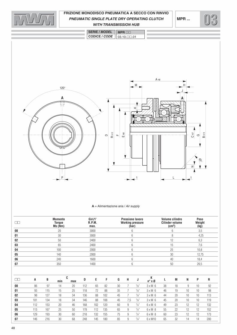
E h8
M
A h8
C H
7
B h1
1
H
J
1 L 1
F G
N
P
K
120°
A A
D R h
11
45°
FRIZIONE MONODISCO PNEUMATICA A SECCO CON RINVIOPNEUMATIC SINGLE PLATE DRY OPERATING CLUTCH
WITH TRANSMISSION HUBMPR ...
�� A B C D E F G H J K L M N P Rmin max n° x Ø00 86 97 14 20 112 65 82 30 7 1/8” 3 x M 6 38 18 9 10 92
01 93 115 15 25 118 72 88 35 7 1/8” 3 x M 6 46 19 10 10 98
02 98 127 18 34 136 88 102 45 7 1/8” 3 x M 6 44 20 10 10 113
03 101 134 18 34 146 88 108 45 7,5 1/8” 3 x M 6 45 20 10 10 119
04 112 153 20 46 168 102 120 60 9 1/4” 6 x M 6 49 23 12 12 132
05 113 167 25 50 178 112 135 65 9 1/4” 6 x M 8 55 22 12 12 152
06 129 193 30 60 218 132 155 75 9 1/4” 6 x M 8 60 23 12 12 173
07 146 216 30 68 248 145 180 85 9 1/4” 6 x M10 65 32 14 14 200
Momento Giri/1’ Pressione lavoro Volume cilindro Peso�� Torque R.P.M. Working pressure Cilinder volume Weight
Ms (Nm) max. (bar) (cm3) (kg)00 20 3000 6 6 3,5
01 30 3000 6 8 4,25
02 50 2400 6 12 6,3
03 65 2400 6 15 7,6
04 100 2000 6 25 10,8
05 140 2000 6 30 12,75
06 240 1600 6 40 18,4
07 350 1400 6 50 26,5
SERIE / MODELCODICE / CODE
MPR ��03.10.��.01
48
A = Alimentazione aria / Air supply
030303
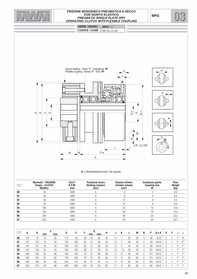
x R - 3 a 120°
P h8
C H
7
B h1
1
K
J
N
L 1
H
Q
A
D E F G
M
A
X
Y
Giunto elastico - Serie “A” - Grandezza “W”Flexible coupling - Series “A” - Size “W”
45°
FRIZIONE MONODISCO PNEUMATICA A SECCOCON GIUNTO ELASTICO
PNEUMATIC SINGLE-PLATE DRYOPERATING CLUTCH WITH FLEXIBLE COUPLING
MPG
�� A B C D E F G H J K L M N P Q x R X Y � �min max min. max00 118 97 14 20 112 85 40 10 26 30 1/8” 7 38 28 4 86 9x10 2 1 1° 9°
01 127 115 15 25 118 100 45 12 30 35 1/8” 7 46 30 4 93 10x10 2 1 1° 6°
02 144 127 18 34 136 120 60 12 38 45 1/8” 7 44 42 4 98 10x10 2 1 1° 7°
03 147 134 18 34 146 120 60 12 38 45 1/8” 7,5 45 42 4 101 10x10 2 1 1° 7°
04 168 153 20 46 168 150 70 15 48 60 1/4” 9 49 50 6 112 12x12 3 1 1° 7°
05 169 167 25 50 178 150 70 15 48 65 1/4” 9 55 50 6 113 12x12 3 1 1° 7°
06 190 193 30 60 218 170 85 15 55 75 1/4” 9 60 55 6 129 12x12 3 1 1° 7°
07 220 216 30 68 248 200 100 20 65 85 1/4” 9 65 66 8 146 14x14 3 1 1° 7°
Momento - FRIZIONE Giri/1’ Pressione lavoro Volume cilindro Grandezza giunto Peso�� Torque - CLUTCH R.P.M. Working ìressure Cilinder volume Coupling size Weight
Ms(Nm) max (bar) (cm3) W (kg)00 20 3000 6 6 2 4,6
01 30 3000 6 8 4 6,5
02 50 2400 6 12 8 8,4
03 65 2400 6 15 8 9,8
04 100 2000 6 25 16 13,6
05 140 2000 6 30 16 15,5
06 240 1600 6 40 25 23,2
07 350 1400 6 50 30 32,7
SERIE / MODELCODICE / CODE
MPG ��03.12.��.01
49
030303
A = Alimentazione aria / Air supply

50
DISTINTA PARTICOLARI1. MOZZO CENTRALE2. CILINDRO3. PISTONE4. ANELLO DI SPINTA5. GUARNIZIONE D’ATTRITO6. ANELLO PREMI MOLLA7. MOLLA8. GUARNIZIONE DI TENUTA9. CUSCINETTO PISTONE
10. CUSCINETTO MOZZO11. ANELLO DI SICUREZZA ESTERNO12. ANELLO DI SICUREZZA INTERNO
� Non è ammesso assolutamente nessun disassamento trale due parti.
MPMP
PARTS LIST1. CENTRAL HUB2. CYLINDER3. PISTON4. THRUST RING5. FRICTION RING6. SPRING COMPRESSION RING7. SPRING8. SEAL RING9. PISTON BEARING
10. HUB BEARING11. OUTER SAFETY RING12. INNER SAFETY RING
� There must never be any disalignment between the twoparts.
MPESEMPIO DI MONTAGGIO EXAMPLE OF MOUNTING
6 7 5 4 3 9 2 8 10
1
11
11 12
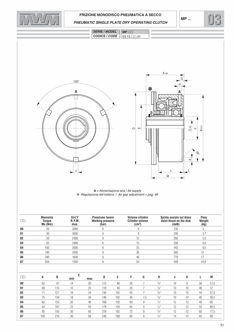
E
A h8
C H
7
B h1
1
G
H
L 1
F
K
J
120°
A A
D
M
45°
FRIZIONE MONODISCO PNEUMATICA A SECCO
PNEUMATIC SINGLE PLATE DRY OPERATING CLUTCH
�� A B C D E F G H J K L Mmin max00 62 97 14 20 112 80 30 7 1/8” 19 9 38 51,5
01 68 115 15 25 118 84 35 7 1/8” 10 10 46 57
02 71 127 18 34 136 102 45 7 1/8” 10 10 44 57,5
03 75 134 18 34 146 102 45 7,5 1/8” 10 10 45 58,5
04 82 153 20 46 168 120 60 9 1/4” 12 12 49 66
05 84 167 25 50 178 126 65 9 1/4” 12 12 55 66,5
06 95 193 30 60 218 162 75 9 1/4” 12 12 60 77,5
07 109 216 30 68 248 188 85 9 1/4” 14 14 65 88
Momento Giri/1’ Pressione lavoro Volume cilindro Spinta assiale sul disco Peso�� Torque R.P.M. Working pressure Cilinder volume Axial thrust on the disk Weight
Ms (Nm) max. (bar) (cm3) (daN) (kg)00 20 3000 6 6 136 3
01 30 3000 6 8 200 3,7
02 50 2400 6 12 260 5,5
03 65 2400 6 15 288 6,6
04 100 2000 6 25 442 9,5
05 140 2000 6 30 560 12
06 240 1600 6 40 778 17
07 350 1400 6 50 948 24,8
SERIE / MODELCODICE / CODE
MP ��03.15.��.01
51
MP ... 030303
A = Alimentazione aria / Air supply�� Regolazione del traferro / Air gap adjustment = pag. 46

52
FRIZIONI PNEUMATICHE MONODISCO A PRESSIONE DIMOLLE A CILINDRO STATICO
Queste frizioni sono adatte solamente per il funzionamento asecco; evitare quindi che la guarnizione d’attrito venga a contat-to con materiali lubrificanti, compromettendo così la coppia ditrasmissione. Se ciò dovesse accadere, pulire le superfici d’attri-to con uno strofinaccio appena inumidito di trielina o benzina.In condizioni operative, questa tipologia di frizione viene mante-nuta innestata da molle elicoidali, che garantiscono la coppia ditrasmissione. Il disinnesto avviene adducendo aria al cilindro dilavoro attraverso il foro di alimentazione «A» posto sul diametroesterno dello stesso e grazie all’azione di una seconda serie dimolle elicoidali.Perché il disinnesto avvenga in maniera completa, è necessariogarantire la pressione di apertura indicata a catalogo; si consi-glia inoltre di montare la valvola di comando, dotata di scaricorapido, il più possibile vicino al cilindro di lavoro, allo scopo diconsentire un innesto veloce e preciso della trasmissione.
MONTAGGIO
Per il montaggio, seguire le istruzioni e gli esempi da noi propo-sti. L’attuatore deve essere ancorato in modo non rigido tramiteuna staffa messa in corrispondenza di una delle fresature ricava-te sullo stesso; la staffa si aggancerà alla fresatura più comoda,in relazione al foro di adduzione dell’aria, tenendo ben presenteche l’attuatore dovrà avere un leggero giuoco sia assiale cheradiale.È molto importante, nella fase di montaggio, controllare attenta-mente il traferro (Q) in 3 punti a 120° con uno spessimetro (vedimisura nelle apposite tabelle).– Montare la frizione.– Aprire la frizione, alimentandola.– Controllare il traferro.
PNEUMATIC SINGLE-PLATE SPRING APPLIED CLUTCHESWITH STATIC CYLINDER
These clutches are suitable only for dry operation and thereforethe friction surfaces should not come in contact with lubricatingmaterials, thus affecting the transmission of torque. If thisoccurs, clean them with a cloth slightly moistened withtrichloroethylene or gasoline.In working conditions, this type of clutch is engaged by the actionof thrust springs, which guarantee the nominal torque. The dis-engagement occurs when air under pressure is supplied to theworking cylinder through the supply bore «A» located on theexternal diameter of the working cylinder itself and by the actionof a second series of thrust springs.In order to obtain a complete disengagement of the clutch, youmust guarantee the release pressure suggested on this cata-logue; we also suggest to mount the command valve, whichmust be equipped with a blow-off device, as close as possible tothe working cylinder, to quickly and precisely engage the trans-mission.
MOUNTING
When mounting, please follow our instructions and examples.The working cylinder must be anchored, but not blocked, bymeans of a bracket or pin engaged on one of the milled spots onthe working cylinder itself; this bracket is to be hooked onto themost convenient milled spot, in relation to the air supply bore,making sure that the working cylinder has some radial and axialplay.During the assembly phase, it is very important to check the airgap (Q) at 3 points at 120° with a thickness gauge; it should beas specified in the relevant tables.– Mount the clutch.– Disengage the clutch feeding air to the cylinder.– Check the air gap.
Q
MP-NGrandezza
SizeTraferro «Q» Air Gap
mm00 0,20 0,3001 0,25 0,3502 0,30 0,4503 0,30 0,4504 0,35 0,5005 0,35 0,5006 0,40 0,6007 0,50 0,70
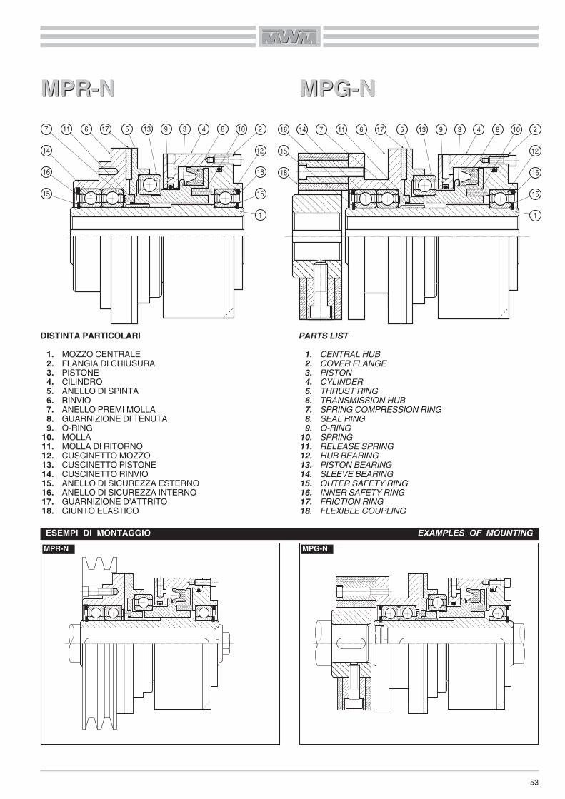
53
DISTINTA PARTICOLARI1. MOZZO CENTRALE2. FLANGIA DI CHIUSURA3. PISTONE4. CILINDRO5. ANELLO DI SPINTA6. RINVIO7. ANELLO PREMI MOLLA8. GUARNIZIONE DI TENUTA9. O-RING
10. MOLLA11. MOLLA DI RITORNO12. CUSCINETTO MOZZO13. CUSCINETTO PISTONE14. CUSCINETTO RINVIO15. ANELLO DI SICUREZZA ESTERNO16. ANELLO DI SICUREZZA INTERNO17. GUARNIZIONE D’ATTRITO18. GIUNTO ELASTICO
PARTS LIST1. CENTRAL HUB2. COVER FLANGE3. PISTON4. CYLINDER5. THRUST RING6. TRANSMISSION HUB7. SPRING COMPRESSION RING8. SEAL RING9. O-RING
10. SPRING11. RELEASE SPRING12. HUB BEARING13. PISTON BEARING14. SLEEVE BEARING15. OUTER SAFETY RING16. INNER SAFETY RING17. FRICTION RING18. FLEXIBLE COUPLING
MPR-NESEMPI DI MONTAGGIO EXAMPLES OF MOUNTING
MPG-N
MPR-NMPR-N MPG-NMPG-N 7 11 17 5 13 3 4 8
12
1
10
15
16
296
14
16
15
7 11 17 5 13 3 4 8
12
1
10
15
16
296
15
16 14
18
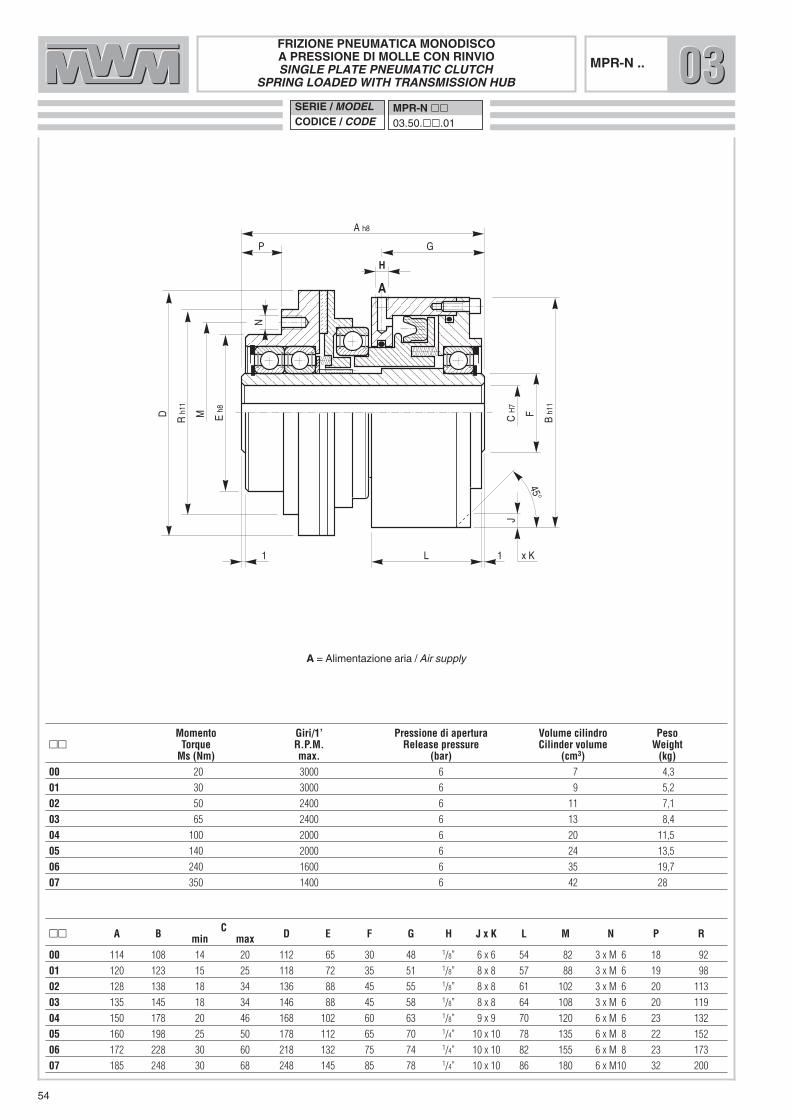
54
E h8
P
A h8
C H
7
B h1
1
G
H
1 L 1
M F
J
N
A
D R h
11
x K
45°
�� A B C D E F G H J x K L M N P Rmin max00 114 108 14 20 112 65 30 48 1/8” 6 x 6 54 82 3 x M 6 18 92
01 120 123 15 25 118 72 35 51 1/8” 8 x 8 57 88 3 x M 6 19 98
02 128 138 18 34 136 88 45 55 1/8” 8 x 8 61 102 3 x M 6 20 113
03 135 145 18 34 146 88 45 58 1/8” 8 x 8 64 108 3 x M 6 20 119
04 150 178 20 46 168 102 60 63 1/8” 9 x 9 70 120 6 x M 6 23 132
05 160 198 25 50 178 112 65 70 1/4” 10 x 10 78 135 6 x M 8 22 152
06 172 228 30 60 218 132 75 74 1/4” 10 x 10 82 155 6 x M 8 23 173
07 185 248 30 68 248 145 85 78 1/4” 10 x 10 86 180 6 x M10 32 200
Momento Giri/1’ Pressione di apertura Volume cilindro Peso�� Torque R.P.M. Release pressure Cilinder volume Weight
Ms (Nm) max. (bar) (cm3) (kg)00 20 3000 6 7 4,3
01 30 3000 6 9 5,2
02 50 2400 6 11 7,1
03 65 2400 6 13 8,4
04 100 2000 6 20 11,5
05 140 2000 6 24 13,5
06 240 1600 6 35 19,7
07 350 1400 6 42 28
A = Alimentazione aria / Air supply
FRIZIONE PNEUMATICA MONODISCOA PRESSIONE DI MOLLE CON RINVIOSINGLE PLATE PNEUMATIC CLUTCH
SPRING LOADED WITH TRANSMISSION HUBSERIE / MODELCODICE / CODE
MPR-N ��03.50.��.01
MPR-N .. 030303

55
Giunto elastico - Serie “A” - Grandezza “W”Flexible coupling - Series “A” - Size “W”
N h8
C H
7
B h1
1
G
H
Q
L 1F
J
A
R E
P
A
X
Y
45°
M H
7
D h
11
x K - n° = S
�� A B C D E F G H J x K L M N P Q R S X Y � �min max min max00 146 108 14 20 85 40 30 48 1/8” 6x6 54 10 26 114 28 4 112 3 2 1 1° 9°
01 154 123 15 25 100 45 35 51 1/8” 8x8 57 12 30 120 30 4 118 3 2 1 1° 6°
02 174 138 18 34 120 60 45 55 1/8” 8x8 61 12 38 128 42 4 136 3 2 1 1° 7°
03 181 145 18 34 120 60 45 58 1/8” 8x8 64 12 38 135 42 4 146 3 2 1 1° 7°
04 206 178 20 46 150 70 60 63 1/8” 9x9 70 15 48 150 50 6 168 3 3 1 1° 7°
05 216 198 25 50 150 70 65 70 1/4” 10x10 78 15 48 160 50 6 178 3 3 1 1° 7°
06 233 228 30 60 170 85 75 74 1/4” 10x10 82 15 55 172 55 6 218 4 3 1 1° 7°
07 259 248 30 68 200 100 85 78 1/4” 10x10 86 20 65 185 66 8 248 4 3 1 1° 7°
Momento Giri/1’ Pressione di apertura Volume cilindro Grandezza giunto Peso�� Torque R.P.M. Release pressure Cilinder volume Coupling size Weight
Ms (Nm) max (bar) (cm3) W (kg)00 20 3000 6 7 2 5,2
01 30 3000 6 9 4 7,6
02 50 2400 6 11 8 9,7
03 65 2400 6 13 8 11,8
04 100 2000 6 20 16 18,5
05 140 2000 6 24 16 23,2
06 240 1600 6 35 25 33,9
07 350 1400 6 42 30 46,4
A = Alimentazione aria / Air supply
FRIZIONE PNEUMATICA MONODISCOA PRESSIONE DI MOLLE CON GIUNTO ELASTICO
SINGLE PLATE PNEUMATIC CLUTCHSPRING LOADED WITH FLEXIBLE COUPLING
SERIE / MODELCODICE / CODE
MPG-N ��03.52.��.01
MPG-N .. 030303

56
DISTINTA PARTICOLARI1. MOZZO CENTRALE2. FLANGIA DI CHIUSURA3. PISTONE4. CILINDRO5. ANELLO DI SPINTA6. ANELLO PREMI MOLLA7. GUARNIZIONE DI TENUTA8. O-RING9. MOLLA
10. MOLLA DI RITORNO11. CUSCINETTO MOZZO12. CUSCINETTO PISTONE13. ANELLO DI SICUREZZA ESTERNO14. ANELLO DI SICUREZZA INTERNO15. GUARNIZIONE D’ATTRITO
MP-NMP-N
PARTS LIST1. CENTRAL HUB2. COVER FLANGE3. PISTON4. CYLINDER5. THRUST RING6. SPRING COMPRESSION RING7. SEAL RING8. O-RING9. SPRING
10. RELEASE SPRING11. HUB BEARING12. PISTON BEARING13. OUTER SAFETY RING14. INNER SAFETY RING15. FRICTION RING
MP-NESEMPIO DI MONTAGGIO EXAMPLE OF MOUNTING
13
6
15 5 12 3 4 7
11
1
9
13
14
2810

57
E
N
C H
7
B h1
1
G
H
L 1
F
J
A
D
A
45°
x K - n° = M
�� A B C D E F G H J x K L M Nmin max00 88 108 14 20 112 80 30 48 1/8” 6 x 6 54 3 80
01 92 123 15 25 118 84 35 51 1/8” 8 x 8 57 3 84,5
02 96 138 18 34 136 102 45 55 1/8” 8 x 8 61 3 88
03 103 145 18 34 146 102 45 58 1/8” 8 x 8 64 3 94
04 114 178 20 46 168 120 60 63 1/8” 9 x 9 70 3 104,5
05 124 198 25 50 178 126 65 70 1/4” 10 x 10 78 3 114
06 132 228 30 60 218 162 75 74 1/4” 10 x 10 82 4 121
07 141 248 30 68 248 188 85 78 1/4” 10 x 10 86 4 128
Momento Giri/1’ Pressione di apertura Volume cilindro Spinta assiale sul disco Peso�� Torque R.P.M. Release pressure Cilinder volume Axial thrust on the disk Weight
Ms (Nm) max (bar) (cm3) daN (kg)00 20 3000 6 7 136 3,7
01 30 3000 6 9 200 5,0
02 50 2400 6 11 260 6,3
03 65 2400 6 13 288 8,3
04 100 2000 6 20 442 12,5
05 140 2000 6 24 560 16,9
06 240 1600 6 35 778 24,3
07 350 1400 6 42 948 31,6
A = Alimentazione aria / Air supply�� Regolazione del traferro / Air gap adjustment = pag. 52
FRIZIONE PNEUMATICA MONODISCO A PRESSIONE DI MOLLE
SINGLE PLATE PNEUMATICCLUTCH SPRING LOADED
SERIE / MODELCODICE / CODE
MP ��03.53.��.01
MP-N ... 030303

58
INNESTI PNEUMATICI A DENTI A CILINDRO STATICO
Le caratteristiche di funzionamento di questi innesti differisconoda quelle delle frizioni solo per la parte di trascinamento: infattinegli innesti la trasmissione del moto è ottenuta mediante denta-tura.Anche negli innesti la coppia è direttamente proporzionale allapressione di alimentazione.Una serie di molle elicoidali, come nelle frizioni, garantisce ilcompleto disinnesto della dentatura di trascinamento, liberandola trasmissione qualora venisse a mancare la pressione di ali-mentazione.Per il buon funzionamento dell’innesto e quindi della trasmissio-ne, è necessario che la pressione di alimentazione sia sempremantenuta ad un valore costante; si consiglia, perciò, l’uso di unpolmone che possa compensare eventuali variazioni della pres-sione.La valvola di comando deve essere montata il più vicino possibi-le al foro di alimentazione posto sul cilindro ed inoltre dovràavere lo scarico rapido, per permettere lo svuotamento del pisto-ne e, di conseguenza, il disinnesto veloce della trasmissione.
MONTAGGIO E REGOLAZIONE DEL TRAFERRO
Per il montaggio, seguire le istruzioni e gli esempi da noi propo-sti. L’attuatore deve essere ancorato in modo non rigido tramiteuna staffa posta in corrispondenza di una delle tre fresature a120° ricavate sullo stesso; la staffa si aggancerà alla fresaturapiù comoda, in relazione al foro di adduzione dell’aria, tenendoben presente che l’attuatore dovrà avere un leggero giuoco siaassiale che radiale.È molto importante, nella fase di montaggio, controllare attenta-mente il traferro (Q) in 3 punti a 120° con uno spessimetro (vedimisura nelle apposite tabelle)
PNEUMATIC TOOTH-TYPE COUPLINGS WITH STATICCYLINDERThese devices differ from clutch couplings only for what con-cerns the entrainment component. In fact, in couplings motion istransmitted through toothing.
In couplings, the torque is also directly proportional to the supplypressureJust like with clutches, a set of helical springs completely disen-gages the entrainment toothing, thus releasing the transmissionduring a total pressure loss.
To ensure that the coupling, and therefore the transmission,operates correctly, the supply pressure must always remain con-stant; therefore, an accumulation tank should be used to com-pensate for any pressure changes.
The control valve must be mounted as close as possible to thesupply hole located on the cylinder and it must also be equippedwith a blow-off device to discharge the piston and, as a conse-quence, to quickly disengage the transmission.
MOUNTING AND AIR GAP ADJUSTMENT
When mounting, please follow our instructions and examples.The working cylinder must be anchored, but not blocked, bymeans of a bracket or pin engaged on one of the three 120°milled spots on the working cylinder itself; this bracket is to behooked onto the most convenient milled spot, in relation to theair supply bore, making sure that the working cylinder has someradial and axial play.During the assembly phase, it is very important to check the airgap (Q) at 3 points at 120° with a thickness gauge; it should beas specified in the relevant tables.
Q
DP Grandezza
SizeTraferro «Q» Air Gap
mm00 0,20 0,3001 0,25 0,3502 0,30 0,4503 0,30 0,4504 0,35 0,5005 0,35 0,5006 0,40 0,6007 0,50 0,70

59
Le dentature possono essere costruite con diverse forme comesegue.
Dentatura triangolare senza gioco � (di serie)Questo tipo di dentatura senza gioco laterale rende possibile l’in-serimento solo da fermo o a velocità sincrona.
Dentatura trapezoidale con gioco laterale �Questo tipo di dentatura rende possibile l’inserimento a velocitàsincrona, oppure ad un numero di giri molto basso.Le soluzioni possibili (a richiesta) sono le seguenti:trascinamento nel solo senso orario o antiorario con una denta-tura a sega � �; possibilità di una o più posizioni a riferimentofisso con dentatura speciale .
The teeth can have any one of a number of designs.
Triangular teeth without play � (standard)This type has no lateral play and only permits engagement whenthere is no movement or when the velocites are synchronous.
Trapezoidal teeth with lateral play �
This type permits engagement when the velocities are synchro-nous, or at a very low R.P.M.On request, the following features are available: dragging inonly one direction (clockwise or counterclockwise), saw-tootheddesign � �; one or more fixed points of reference, specialtooth design .
1 2 3 4 5
3 43 4

60
DISTINTA PARTICOLARI1. MOZZO CENTRALE2. CILINDRO3. PISTONE4. ANELLO DENTATO5. MOLLA6. ANELLO PREMI MOLLA7. RINVIO8. GUARNIZIONE DI TENUTA9. CUSCINETTO RINVIO
10. CUSCINETTO PISTONE11. CUSCINETTO MOZZO12. ANELLO DI SICUREZZA ESTERNO13. ANELLO DI SICUREZZA INTERNO14. FLANGIA PER GIUNTO15. GIUNTO ELASTICO
DPRDPR DPGDPG
PARTS LIST1. CENTRAL HUB2. CYLINDER3. PISTON4. TOOTHED RING5. SPRING6. SPRING COMPRESSION RING7. TRANSMISSION HUB8. SEAL RING9. SLEEVE BEARING
10. PISTON BEARING11. HUB BEARING12. OUTER SAFETY RING13. INNER SAFETY RING14. COUPLING FLANGE15. FLEXIBLE COUPLING
DPRESEMPI DI MONTAGGIO EXAMPLES OF MOUNTING
DPG
9 6 7 5 4 3 10 2 8
11
1
12
13
12
13
9 6 7
5 4 3 10 2 8
11
1
1415
12
13
12
13

D E h8
P
A h8
C H
7
B h1
1
G
H
1 L 1
M F
K
J
N
120°
A A
45°
INNESTO PNEUMATICO A DENTI CON RINVIOTOOTH-TYPE PNEUMATIC COUPLING
WITH TRANSMISSION HUB
�� A B C D E F G H J K L M N Pmin max n° x Ø00 86 97 14 20 92 65 30 7 1/8” 10 9 38 82 3 x M 6 18
01 93 115 15 25 99 72 35 7 1/8” 10 10 46 88 3 x M 6 19
02 98 127 18 34 115 88 45 7 1/8” 10 10 44 102 3 x M 6 20
03 101 134 18 34 124 88 45 7,5 1/8” 10 10 45 108 3 x M 6 20
04 112 153 20 46 137 102 60 9 1/4” 12 12 49 120 6 x M 6 23
05 113 167 25 50 153 112 65 9 1/4” 12 12 55 135 6 x M 8 22
06 129 193 30 60 178 132 75 9 1/4” 12 12 60 155 6 x M 8 23
07 146 216 30 68 209 145 85 9 1/4” 14 14 65 180 6 x M10 32
Momento Giri/1’ Pressione lavoro Volume cilindro Peso�� Torque R.P.M. Working pressure Cilinder volume Weight
Ms (Nm) max. (bar) (cm3) (kg)00 110 3000 6 6 3,4
01 160 3000 6 8 4,1
02 260 2400 6 12 6
03 350 2400 6 15 7,3
04 550 2000 6 25 10,5
05 750 2000 6 30 12,4
06 1300 1600 6 40 18
07 2100 1400 6 50 26
SERIE / MODELCODICE / CODE
DPR ��03.20.��.01
61
DPR .. 030303
A = Alimentazione aria / Air supply
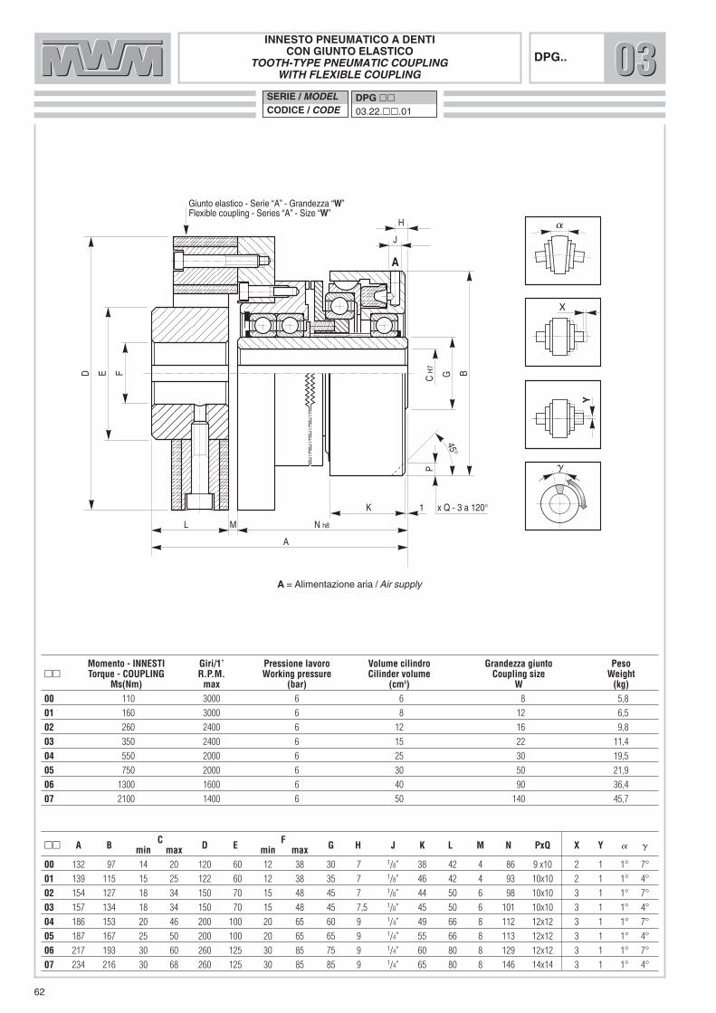
INNESTO PNEUMATICO A DENTICON GIUNTO ELASTICO
TOOTH-TYPE PNEUMATIC COUPLINGWITH FLEXIBLE COUPLING
SERIE / MODELCODICE / CODE
DPG ��03.22.��.01
62
C H
7
B
H
J
L
K 1
G
P
A
D E F
N h8M
A
X
Y
Giunto elastico - Serie “A” - Grandezza “W”Flexible coupling - Series “A” - Size “W”
x Q - 3 a 120°
45°
DPG..
�� A B C D E F G H J K L M N PxQ X Y � �min max min max00 132 97 14 20 120 60 12 38 30 7 1/8” 38 42 4 86 9 x10 2 1 1° 7°
01 139 115 15 25 122 60 12 38 35 7 1/8” 46 42 4 93 10x10 2 1 1° 4°
02 154 127 18 34 150 70 15 48 45 7 1/8” 44 50 6 98 10x10 3 1 1° 7°
03 157 134 18 34 150 70 15 48 45 7,5 1/8” 45 50 6 101 10x10 3 1 1° 4°
04 186 153 20 46 200 100 20 65 60 9 1/4” 49 66 8 112 12x12 3 1 1° 7°
05 187 167 25 50 200 100 20 65 65 9 1/4” 55 66 8 113 12x12 3 1 1° 4°
06 217 193 30 60 260 125 30 85 75 9 1/4” 60 80 8 129 12x12 3 1 1° 7°
07 234 216 30 68 260 125 30 85 85 9 1/4” 65 80 8 146 14x14 3 1 1° 4°
Momento - INNESTI Giri/1’ Pressione lavoro Volume cilindro Grandezza giunto Peso�� Torque - COUPLING R.P.M. Working pressure Cilinder volume Coupling size Weight
Ms(Nm) max (bar) (cm3) W (kg)00 110 3000 6 6 8 5,8
01 160 3000 6 8 12 6,5
02 260 2400 6 12 16 9,8
03 350 2400 6 15 22 11,4
04 550 2000 6 25 30 19,5
05 750 2000 6 30 50 21,9
06 1300 1600 6 40 90 36,4
07 2100 1400 6 50 140 45,7
030303
A = Alimentazione aria / Air supply

63
DISTINTA PARTICOLARI1. MOZZO CENTRALE2. CILINDRO3. PISTONE4. ANELLO DENTATO5. MOLLA6. ANELLO PREMI MOLLA7. CAMPANA DENTATA8. FLANGIA DENTATA9. GUARNIZIONE DI TENUTA
10. CUSCINETTO FLANGIA11. CUSCINETTO PISTONE12. CUSCINETTO MOZZO13. ANELLO DI SICUREZZA ESTERNO14. ANELLO DI SICUREZZA INTERNO
� Non è ammesso assolutamente nessun disassamento trale due parti.
DPFDPF DPDP
PARTS LIST1. CENTRAL HUB2. CYLINDER3. PISTON4. TOOTHED RING5. SPRING6. SPRING COMPRESSION RING7. TOOTHED CUP8. TRANSMISSION FLANGE9. SEAL RING
10. FLANGE BEARING11. PISTON BEARING12. SLEEVE BEARING13. OUTER SAFETY RING14. INNER SAFETY RING
� There must never be any disalignment between the twoparts.
DPFESEMPI DI MONTAGGIO EXAMPLES OF MOUNTING
DP
8 6 5 4 3 11 2 9 12
1
10
14
13
13
14
6 7 5 4 3 11 2 9 12
1
13
14

INNESTO PNEUMATICO A DENTI CON FLANGIATOOTH-TYPE PNEUMATIC COUPLING WITH FLANGE
SERIE / MODELCODICE / CODE
DPF ��03.24.��.01
64
E H
6
P
A h8
C H
7
B h1
1
G
H
1 L 1
M F
J
N*
A
R
D h
8
Q
K
120°
A
45°
DPF ..
�� A B C D E F G H J K L M N* P Q Rmin max n° x Ø00 73 97 14 20 98 55 30 7 1/8” 9 10 38 86 M 6 3 72 11
01 79 115 15 25 111 62 35 7 1/8” 10 10 46 90 M 6 3 78 13
02 82 127 18 34 124 75 45 7 1/8” 10 10 44 110 M 6 3 81 14
03 85 134 18 34 136 75 45 7,5 1/8” 10 10 45 120 M 6 3 84 14
04 93 153 20 46 149 95 60 9 1/4” 12 12 49 130 M 6 3 92 14
05 95 167 25 50 162 100 65 9 1/4” 12 12 55 140 M 8 3 94 17
06 108 193 30 60 194 115 75 9 1/4” 12 12 60 170 M 8 3 107 17
07 123 216 30 68 213 130 85 9 1/4” 14 14 65 190 M10 7 122 21
Momento Giri/1’ Pressione lavoro Volume cilindro Peso�� Torque R.P.M. Working pressure Cilinder volume Weight
Ms (Nm) max. (bar) (cm3) (kg)00 110 3000 6 6 3,4
01 160 3000 6 8 4,1
02 260 2400 6 12 6
03 350 2400 6 15 7,3
04 550 2000 6 25 10,5
05 750 2000 6 30 12,4
06 1300 1600 6 40 18
07 2100 1400 6 50 26
030303
A = Alimentazione aria / Air supply
* FORATURA FLANGIA / FLANGE DRILLING:
SI POSSONO USARE / YOU CAN USE: DPF 00 ÷ 03 = n° 3 a 120° or n° 4 a 90°DPF 04 ÷ 07 = n° 4 a 90° or n° 6 a 60°
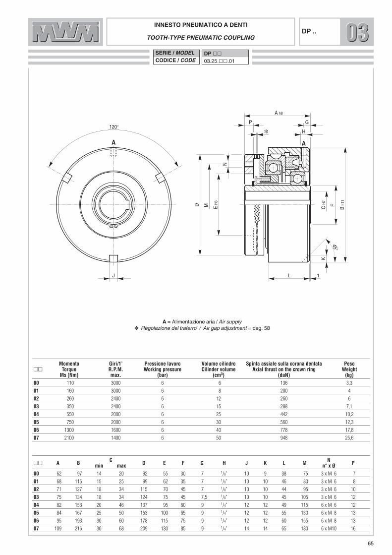
INNESTO PNEUMATICO A DENTITOOTH-TYPE PNEUMATIC COUPLING
SERIE / MODELCODICE / CODE
DP ��03.25.��.01
65
E H
6
A h8
C H
7
B h1
1
G
H
L 1
M F
K
N
A
P
D
J
120°
A
45°
DP ..
�� A B C D E F G H J K L M N Pmin max n° x Ø00 62 97 14 20 92 55 30 7 1/8” 10 9 38 75 3 x M 6 7
01 68 115 15 25 99 62 35 7 1/8” 10 10 46 80 3 x M 6 8
02 71 127 18 34 115 70 45 7 1/8” 10 10 44 95 3 x M 6 10
03 75 134 18 34 124 75 45 7,5 1/8” 10 10 45 105 3 x M 6 12
04 82 153 20 46 137 95 60 9 1/4” 12 12 49 115 6 x M 6 12
05 84 167 25 50 153 100 65 9 1/4” 12 12 55 130 6 x M 8 13
06 95 193 30 60 178 115 75 9 1/4” 12 12 60 155 6 x M 8 13
07 109 216 30 68 209 130 85 9 1/4” 14 14 65 180 6 x M10 16
Momento Giri/1’ Pressione lavoro Volume cilindro Spinta assiale sulla corona dentata Peso�� Torque R.P.M. Working pressure Cilinder volume Axial thrust on the crown ring Weight
Ms (Nm) max. (bar) (cm3) (daN) (kg)00 110 3000 6 6 136 3,3
01 160 3000 6 8 200 4
02 260 2400 6 12 260 6
03 350 2400 6 15 288 7,1
04 550 2000 6 25 442 10,2
05 750 2000 6 30 560 12,3
06 1300 1600 6 40 778 17,8
07 2100 1400 6 50 948 25,6
030303
A = Alimentazione aria / Air supply�� Regolazione del traferro / Air gap adjustment = pag. 58

66
INNESTI PNEUMATICI A DENTI A PRESSIONE DI MOLLE A CILINDRO STATICO
A differenza di quelli positivi, in condizioni operative questi inne-sti vengono mantenuti ingranati da una serie di molle elicoidali,che garantiscono la coppia di trasmissione.Il disinnesto avviene adducendo aria al cilindro di lavoro attra-verso il foro di alimentazione «A» posto sul diametro esternodello stesso.Perché il disinnesto avvenga in maniera completa, è necessariogarantire la pressione di apertura indicata a catalogo; si consi-glia inoltre di montare la valvola di comando, dotata di scaricorapido, il più possibile vicino al cilindro di lavoro, allo scopo diconsentire un innesto veloce e preciso della trasmissione
MONTAGGIO E REGOLAZIONE DEL TRAFERRO
Per il montaggio, seguire le istruzioni e gli esempi da noi propo-sti. L’attuatore deve essere ancorato in modo non rigido tramiteuna staffa posta in corrispondenza di una delle fresature ricava-te sullo stesso; la staffa si aggancerà alla fresatura più comoda,in relazione al foro di adduzione dell’aria, tenendo ben presenteche l’attuatore dovrà avere un leggero giuoco sia assiale cheradiale.È molto importante, nella fase di montaggio, controllare attenta-mente il traferro (Q) in 3 punti a 120° con uno spessimetro (vedimisura nelle apposite tabelle)– Montare l’innesto a dentini.– Innestare la dentatura.– Aprire l’innesto alimentandolo.– Controllare il traferro.
PNEUMATIC SPRING APPLIED TOOTH-TYPE COUPLINGSWITH STATIC CYLINDER
Contrary to the spring released ones, in working conditionsthese couplings are engaged by the action of thrust springs,which guarantee the nominal torque.The disengagement occurs when air under pressure is suppliedto the working cylinder through the supply bore «A» located onthe external diameter of the working cylinder itself.In order to obtain a complete disengagement of the coupling,you must guarantee the release pressure suggested on this cat-alogue; we also suggest to mount the command valve, whichmust be equipped with a blow-off device, as close as possible tothe working cylinder, to quickly and precisely engage the trans-mission.
MOUNTING AND AIR GAP ADJUSTMENT
When mounting, please follow our instructions and examples.The working cylinder must be anchored, but not blocked, bymeans of a bracket or pin engaged on one of the three 120°milled spots on the working cylinder itself; this bracket is to behooked onto the most convenient milled spot, in relation to theair supply bore, making sure that the working cylinder has someradial and axial play.During the assembly phase, it is very important to check the airgap (Q) at 3 points at 120° with a thickness gauge; it should beas specified in the relevant tables.– Mount the tooth-type coupling.– The toothing has to be engaged.– Disengage the coupling feeding air to the cylinder.– Check the air gap.
Q
DP-N Grandezza
SizeTraferro «Q» Air Gap
mm00 0,20 0,3001 0,25 0,3502 0,30 0,4503 0,30 0,4504 0,35 0,5005 0,35 0,5006 0,40 0,6007 0,50 0,70

67
Le dentature possono essere costruite con diverse forme comesegue.
Dentatura triangolare senza gioco � (di serie)Questo tipo di dentatura senza gioco laterale rende possibile l’in-serimento solo da fermo o a velocità sincrona.
Dentatura trapezoidale con gioco laterale �Questo tipo di dentatura rende possibile l’inserimento a velocitàsincrona, oppure ad un numero di giri molto basso.Le soluzioni possibili (a richiesta) sono le seguenti:trascinamento nel solo senso orario o antiorario con una denta-tura a sega � �; possibilità di una o più posizioni a riferimentofisso con dentatura speciale .
The teeth can have any one of a number of designs.
Triangular teeth without play � (standard)This type has no lateral play and only permits engagement whenthere is no movement or when the velocites are synchronous.
Trapezoidal teeth with lateral play �
This type permits engagement when the velocities are synchro-nous, or at a very low R.P.M.On request, the following features are available: dragging inonly one direction (clockwise or counterclockwise), saw-tootheddesign � �; one or more fixed points of reference, specialtooth design .
1 2 3 4 5
3 43 4

68
DISTINTA PARTICOLARI1. MOZZO CENTRALE2. FLANGIA DI CHIUSURA3. PISTONE4. CILINDRO5. ANELLO DENTATO6. RINVIO7. ANELLO PREMI MOLLA8. GUARNIZIONE DI TENUTA9. O-RING
10. MOLLA11. MOLLA DI RITORNO12. CUSCINETTO MOZZO13. CUSCINETTO PISTONE14. CUSCINETTO RINVIO15. ANELLO DI SICUREZZA ESTERNO16. ANELLO DI SICUREZZA INTERNO17. FLANGIA PORTA GIUNTO18. GIUNTO ELASTICO
DPR-NDPR-N DPG-NDPG-N
PARTS LIST1. CENTRAL HUB2. COVER FLANGE3. PISTON4. CYLINDER5. TOOTHED RING6. TRANSMISSION HUB7. SPRING COMPRESSION RING8. SEAL RING9. O-RING
10. SPRING11. RELEASE SPRING12. HUB BEARING13. PISTON BEARING14. SLEEVE BEARING15. OUTER SAFETY RING16. INNER SAFETY RING17. FLEXIBLE COUPLING FLANGE18. FLEXIBLE COUPLING
ESEMPI DI MONTAGGIO EXAMPLES OF MOUNTINGDPG-NDPR-N
7 6 11 5 13 3 4 8 2
1
14
109
16
15
16
15
12
7 6 11 5 13 3 4 8 2
1
14 109
16
15
16
15 12
18
17

69
INNESTO PNEUMATICO A DENTIA PRESSIONE DI MOLLE CON RINVIO
TOOTH-TYPE PNEUMATIC COUPLING SPRING LOADEDWITH TRANSMISSION HUB
SERIE / MODELCODICE / CODE
DPR-N ��03.60.��.01
45°
x K - n° = M
E h8RD C
H7
B h1
1
F
J1 L 1
P
A h8
G
H
NA
DPR-N..
�� A B C D E F G H J x K L M N P Rmin max00 114 108 14 20 92 65 30 48 1/8” 6 x 6 54 3 3 x M6 18 82
01 120 123 15 25 99 72 35 51 1/8” 8 x 8 57 3 3 x M6 19 88
02 128 138 18 34 115 88 45 55 1/8” 8 x 8 61 3 3 x M6 20 102
03 135 145 18 34 124 88 45 58 1/8” 8 x 8 64 3 3 x M6 20 108
04 150 178 20 46 137 102 60 63 1/8” 9 x 9 70 3 6 x M6 23 120
05 160 198 25 50 153 112 65 70 1/4” 10 x 10 78 3 6 x M8 22 135
06 172 228 30 60 178 132 75 74 1/4” 10 x 10 82 4 6 x M8 23 155
07 185 248 30 68 209 145 85 78 1/4” 10 x 10 86 4 6 x M10 32 180
Momento Giri/1’ Pressione di apertura Volume cilindro Peso�� Torque R.P.M. Release pressure Cilinder volume Weight
Ms(Nm) max (bar) (cm3) (kg)00 110 3000 6 8 4,3
01 160 3000 6 12 5,2
02 260 2400 6 17 7,1
03 350 2400 6 18 8,4
04 550 2000 6 38 11,5
05 750 2000 6 45 13,5
06 1300 1600 6 63 19,7
07 2100 1400 6 73 28
030303
A = Alimentazione aria / Air supply

INNESTO PNEUMATICO A DENTIA PRESSIONE DI MOLLE CON GIUNTO ELASTICO
TOOTH-TYPE PNEUMATIC COUPLING SPRING LOADEDWITH FLEXIBLE COUPLING
DPG-N.. 030303SERIE / MODELCODICE / CODE
DPG-N ��03.62.��.01
70
C H
7
B h1
1
G
H
Q
L 1
F
J
A
D E R
N h8P
A
X
Y
Giunto elastico - Serie “A” - Grandezza “W”Flexible coupling - Series “A” - Size “W”
45°
x K - n° = M
�� A B C D E F G H J x K L M N P Q R X Y � �min max min max00 160 108 14 20 120 60 30 48 1/8” 6 x 6 54 3 114 42 4 12 38 2 1 1° 7°
01 166 123 15 25 122 60 35 51 1/8” 8 x 8 57 3 120 42 4 12 38 2 1 1° 4°
02 184 138 18 34 150 70 45 55 1/8” 8 x 8 61 3 128 50 6 15 48 3 1 1° 7°
03 191 145 18 34 150 70 45 58 1/8” 8 x 8 64 3 135 50 6 15 48 3 1 1° 4°
04 224 178 20 46 200 100 60 63 1/8” 9 x 9 70 3 150 66 8 20 65 3 1 1° 7°
05 234 198 25 50 200 100 65 70 1/4” 10 x 10 78 3 160 66 8 20 65 3 1 1° 4°
06 260 228 30 60 260 125 75 74 1/4” 10 x 10 82 4 172 80 8 30 85 3 1 1° 7°
07 273 248 30 68 260 125 85 78 1/4” 10 x 10 86 4 185 80 8 30 85 3 1 1° 4°
Momento Giri/1’ Volume cilindro Grandezza giunto Peso�� Torque R.P.M. Cilinder volume Coupling size Weight
Ms(Nm) max (cm3) W (kg)00 110 3000 8 8 7,0
01 160 3000 12 12 8,4
02 260 2400 17 16 11,8
03 350 2400 18 22 14,4
04 550 2000 38 30 23,9
05 750 2000 45 50 29,6
06 1300 1600 63 90 47,5
07 2100 1400 73 140 57,6
A = Alimentazione aria / Air supply

71
DISTINTA PARTICOLARI1. MOZZO CENTRALE2. FLANGIA DI CHIUSURA3. PISTONE4. CILINDRO5. ANELLO DENTATO6. CAMPANA DENTATA7. ANELLO PREMI MOLLA8. GUARNIZIONE DI TENUTA9. O-RING
10. MOLLA11. MOLLA DI RITORNO12. CUSCINETTO MOZZO13. CUSCINETTO PISTONE14. ANELLO DI SICUREZZA ESTERNO15. ANELLO DI SICUREZZA INTERNO
� Non è ammesso assolutamente nessun disassamento trale due parti.
DP-NDP-N
PARTS LIST1. CENTRAL HUB2. COVER FLANGE3. PISTON4. CYLINDER5. TOOTHED RING6. TOOTHED HUB7. SPRING COMPRESSION RING8. SEAL RING9. O-RING
10. SPRING11. RELEASE SPRING12. HUB BEARING13. PISTON BEARING14. OUTER SAFETY RING15. INNER SAFETY RING
� There must never be any disalignment between the twoparts.
ESEMPI DI MONTAGGIO EXAMPLES OF MOUNTINGDP-N
7
6 11 5 13 3 4 8 2
1
14
109
15
14
12
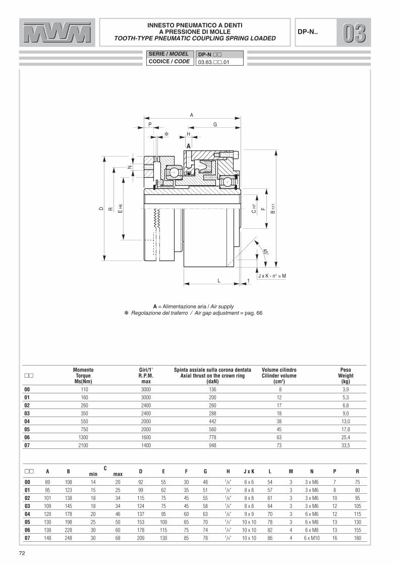
72
INNESTO PNEUMATICO A DENTIA PRESSIONE DI MOLLE
TOOTH-TYPE PNEUMATIC COUPLING SPRING LOADED
SERIE / MODELCODICE / CODE
DP-N ��03.63.��.01
E H
6A
C H
7
B h1
1
G
H
L 1
R F
N
A
P
D
45°
J x K - n° = M
DP-N..
�� A B C D E F G H J x K L M N P Rmin max00 89 108 14 20 92 55 30 48 1/8” 6 x 6 54 3 3 x M6 7 75
01 95 123 15 25 99 62 35 51 1/8” 8 x 8 57 3 3 x M6 8 80
02 101 138 18 34 115 75 45 55 1/8” 8 x 8 61 3 3 x M6 10 95
03 109 145 18 34 124 75 45 58 1/8” 8 x 8 64 3 3 x M6 12 105
04 120 178 20 46 137 95 60 63 1/8” 9 x 9 70 3 6 x M6 12 115
05 130 198 25 50 153 100 65 70 1/4” 10 x 10 78 3 6 x M8 13 130
06 138 228 30 60 178 115 75 74 1/4” 10 x 10 82 4 6 x M8 13 155
07 148 248 30 68 209 130 85 78 1/4” 10 x 10 86 4 6 x M10 16 180
Momento Giri/1’ Spinta assiale sulla corona dentata Volume cilindro Peso�� Torque R.P.M. Axial thrust on the crown ring Cilinder volume Weight
Ms(Nm) max (daN) (cm3) (kg)00 110 3000 136 8 3,9
01 160 3000 200 12 5,3
02 260 2400 260 17 6,8
03 350 2400 288 18 9,0
04 550 2000 442 38 13,0
05 750 2000 560 45 17,8
06 1300 1600 778 63 25,4
07 2100 1400 948 73 33,5
030303
A = Alimentazione aria / Air supply�� Regolazione del traferro / Air gap adjustment = pag. 66

73
FRENI PNEUMATICI/OLEODINAMICI MULTIDISCO
Per facilitare la loro applicazione, questi freni vengono prodotti indue versioni, che differiscono principalmente dal punto di vistacostruttivo e di montaggio ma che possiedono le stesse caratte-ristiche tecniche. La prima (IBL/SC e PBL-BF/SC) si applica montando il freno sudi un albero fisso, sul quale andrà successivamente montata inmodo libero una campana, fresata da un lato per ancorare idischi esterni del freno; sull’altro lato della stessa si fisserà ilcinematismo che si vuole frenare.La seconda (IBL e PBL-BF) si applica fissando il freno a parete emontando sull’albero rotante un mozzo fresato che va ad impe-gnare le alette dei dischi interni.In entrambe le versioni, i cilindri di lavoro sono statici, con tutti ivantaggi che sono stati ampiamente descritti nell’introduzionealle frizioni a cilindro statico.Per applicazioni in bagno d’olio o in presenza di nebbia d’olio(IBL e IBL/SC), i freni vengono realizzati con dischi tutti inacciaio. Per applicazioni a secco (PBL-BF e PBL/SC-BF), invece, i freni vengono realizzati con dischi misti in bronzo e acciaio.Per l’alimentazione dei modelli oleodinamici l’olio da usare è lostesso consigliato per le frizioni.
DETERMINAZIONE APPROSSIMATIVA DEL MOMENTOSTATICO IN RELAZIONE ALLA PRESSIONE DI LAVORO
PNEUMATIC/HYDRAULIC MULTIDISK BRAKES
To make as easy as possible their application, two variants ofthese brakes are available, which differ from each other substan-tially from a point of view of construction and application, butboth of them with the same technical characteristics.The first type (IBL/SC and PBL-BF/SC) has to be keyed to afixed shaft, to which is then freely mounted a cup housing: onone side, this cup housing is milled to anchoring the outer disksof the brake. The moving components to be braked are fixed onthe other side.The second type (IBL and PBL-BF) has to be fixed to a wall anda milled hub has to be mounted on the rotating shaft; this hub willinserts into the fins of the inner disks.Both types have fixed cylinders with working pistons, the advan-tages of which are fully described in the introduction regardingstatic-cylinder clutches.For usage in an oil bath or in the presence of an oil mist (IBL andIBL/SC), the brake disks are all made of steel.
For dry application (PBL-BF and PBL/SC-BF), a combination of bronze and steel brake disks is used.For the hydraulic model, the recommended type of oil is thesame recommended for clutches
APPROXIMATED DETERMINATION OF STATIC MOMENT INRELATION TO WORKING PRESSURE.
IBL 2/
SC
0
0
2
4
6
8
10
12
1415
50 100 150 200 300 400 500 600 700 900 100 1100800
IBL 3
IBL 4
/LIB
L 4IBL
4/SC
IBL 6
IBL 6/
SC
IBL 1
0/SC
MOMENTO / TORQUE (Nm)
PRES
SION
E D
I LAV
ORO
WOR
KING
PRE
SSUR
E (Bar)

74
DISTINTA PARTICOLARI1. MOZZO CENTRALE2. CILINDRO3. PISTONE4. GUARNIZIONE DI TENUTA5. PIATTELLO DI TESTA6. DISCO INTERNO7. DISCO ESTERNO8. ANELLO DI SICUREZZA9. ANELLO DI SICUREZZA
10. CAMPANA (A RICHIESTA)
IBL/SCIBL/SC
PARTS LIST1. CENTRAL HUB2. CYLINDER3. PISTON4. SEAL RING5. HEAD PLATE6. INNER DISK7. OUTER DISK8. SAFETY RING9. SAFETY RING
10. CUP HOUSING (ON DEMAND)
ESEMPIO DI MONTAGGIO EXAMPLE OF MOUNTING
5 7 6 3 4 2 9 1
8
10
PBL/SC-BF PBL/SC-BF
IBL/SC PBL/SC-BF
PNEUMATICA A SECCO /PNEUMATIC DRY APPLICATION
OLEODINAMICA A OLIOHYDRAULIC IN OIL BATH

75
��
FRENO OLEODINAMICO/PNEUMATICO MULTIDISCOA CILINDRO STATICO
HYDRAULIC/PNEUMATIC STATIC CYLINDERMULKTIDISK BRAKE
SERIE / MODELCODICE / CODE
IBL ��/SC03.03.��.01
PBL ��/SC-BF03.03.��.51
H
G F
P
A h8
C H
7
B h1
1
N
J
E h1
1
D
IBL .../SCPBL .../SC-BF
C Alette�� A B min. max D E F G H J N P Lugs
N.02 71 89 16 26 33 88 0,5 7 1/8” 12 27,5 21,5 3
04 85 120 20 40 46 112 1 6 1/8” 16 31 25 8
06 99 145 25 48 58 130 1 9 1/4” 16 46 37 8
10 115 218 30 58 70 180 2 10 1/4” 20 63 50 10
Momenti Pressione lavoro Volume cilindro Giri/1’ Peso Dischi esterni Campana�� Torques Working pressure Cylinder volume R.P.M. limit Weight External plates Cap Housing
a richiesta/on demandMi (Nm) Ms (Nm) (bar) (cm3) max (kg) N. �
02 40 70 8 7 3600 2,2 5 C 02.01
04 90 160 8 13 3200 4,5 6 C 05.01
06 180 340 8 16 2800 8,5 8 C 06.01
10 450 750 8 42 2200 18 6 C 10.02
030303
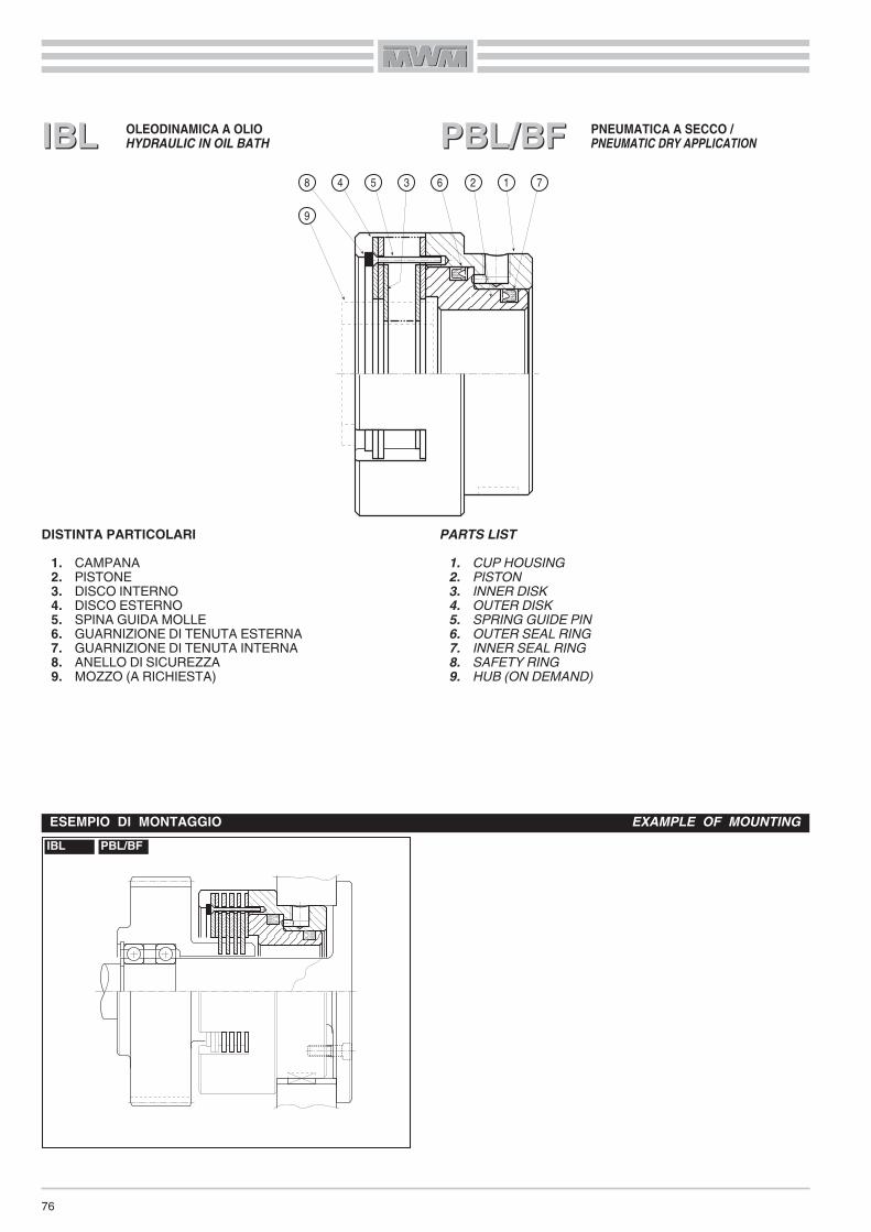
PBL/BF
76
DISTINTA PARTICOLARI1. CAMPANA2. PISTONE3. DISCO INTERNO4. DISCO ESTERNO5. SPINA GUIDA MOLLE6. GUARNIZIONE DI TENUTA ESTERNA7. GUARNIZIONE DI TENUTA INTERNA8. ANELLO DI SICUREZZA9. MOZZO (A RICHIESTA)
IBLIBL PBL/BF
PARTS LIST1. CUP HOUSING2. PISTON3. INNER DISK4. OUTER DISK5. SPRING GUIDE PIN6. OUTER SEAL RING7. INNER SEAL RING8. SAFETY RING9. HUB (ON DEMAND)
ESEMPIO DI MONTAGGIO EXAMPLE OF MOUNTINGIBL PBL/BF
8 4 5 3 6 2 1 7
9
PNEUMATICA A SECCO /PNEUMATIC DRY APPLICATION
OLEODINAMICA A OLIOHYDRAULIC IN OIL BATH
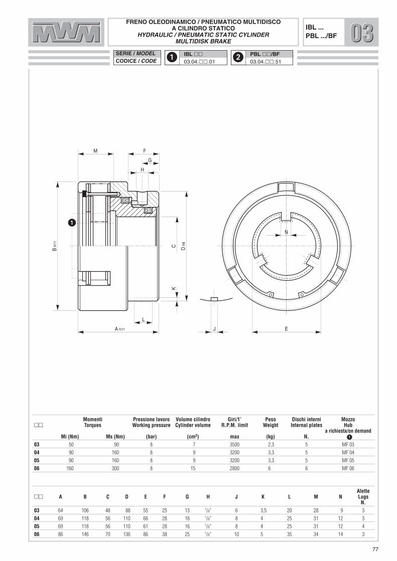
77
��
FRENO OLEODINAMICO / PNEUMATICO MULTIDISCOA CILINDRO STATICO
HYDRAULIC / PNEUMATIC STATIC CYLINDERMULTIDISK BRAKE
SERIE / MODELCODICE / CODE
IBL ��03.04.��.01
PBL ��/BF03.04.��.51
A h11
C
B h1
1
M
E
D h
6
H
G
F
N
J
K
L
IBL ...PBL .../BF
Alette�� A B C D E F G H J K L M N Lugs
N.03 64 106 48 88 55 25 13 1/8” 6 3,5 20 28 9 3
04 69 118 56 110 66 28 16 1/8” 8 4 25 31 12 3
05 69 118 56 110 61 28 16 1/8” 8 4 25 31 12 4
06 86 146 70 136 86 38 25 1/8” 10 5 35 34 14 3
Momenti Pressione lavoro Volume cilindro Giri/1’ Peso Dischi interni Mozzo�� Torques Working pressure Cylinder volume R.P.M. limit Weight Internal plates Hub
a richiesta/on demandMi (Nm) Ms (Nm) (bar) (cm3) max (kg) N. �
03 50 90 8 7 3500 2,3 5 MF 03
04 90 160 8 9 3200 3,3 5 MF 04
05 90 160 8 9 3200 3,3 5 MF 05
06 160 300 8 15 2800 6 6 MF 06
030303
78
FRENI PNEUMATICI/OLEODINAMICI MULTIDISCO POSITIVI
Robusti ed affidabili, questi freni si propongono per tutte quelleapplicazioni che richiedono potenza e precisione nella frenata.Di semplice costruzione, risultano composti da un pacco dischi,da una campana e da un pistone che insieme costituiscono l’at-tuatore pneumatico/oleodinamico fisso.L’adduzione dell’aria/olio in pressione, attraverso il foro «A» suldiametro esterno del cilindro, permette di evitare complicati per-corsi di alimentazione e dà la possibilità di montare più freni sullostesso albero.Il pistone viene riportato in posizione di riposo da una serie dimolle, le quali generano una forza di pressione assiale che influi-sce con valori minimi sulla spinta di lavoro. La corsa del pistone e le molle permettono il recupero dell’usuradei dischi, escludendo la necessità di registrazione. Inoltre, ilmontaggio delle molle stesse tra i dischi evita trascinamenti ariposo, consentendo l’installazione del freno in posizione vertica-le (in presenza di cinematismi molto sensibili o laddove siarichiesta una maggiore precisione nel disinnesto.)
Per il funzionamento a secco, questa tipologia di freni si avvaledi un pacco dischi in bronzo/acciaio che di fatto consente di ope-rare in assenza di lubrificazione.Per ottenere la coppia frenante nominale, è necessario garantireil valore di pressione indicato. La valvola di comando, inoltre,deve essere montata il più vicino possibile al foro di alimentazio-ne posto sul cilindro e dovrà essere dotata di scarico rapido perpermettere lo svuotamento dell’attuatore con la conseguenteapertura veloce del freno.
MONTAGGIO
Questi freni vanno montati bloccando con viti o bulloni il corpoesterno sulla carcassa della macchina o su di un altro supportofisso e montando sull’albero rotante il mozzo fresato (a richie-sta) che va ad inserirsi nelle alette dei dischi interni (vedi esem-pio di montaggio).
PNEUMATICALLY/HYDRAULICALLY APPLIED MULTI-DISKBRAKES
Strong and reliable, these brakes are perfect for those applica-tions where power and precision in braking are required.Their simple design includes a disk pack, a cup housing and apiston which together form the fixed pneumatic/hydraulic actua-tor.Air/oil under pressure enters through external bore «A», a solu-tion which permits the elimination of complicated channeling andallows several brakes to be mounted on the same shaft.
A series of disk separating springs, generates sufficient axialpressure to allow the quick return of the piston to its neutral posi-tion, impacting minimally on the working thrust.Piston stroke and the thrust springs allow disk-wear take-up ,thus eliminating the need of adjustment. Furthermore, mountingof the springs between the disks prevents most of the draggingwhen the brake is in the neutral position, allowing its installationin a vertical position ( in the presence of very sensitive kinematicor where greater uncoupling precision is required.)
For dry applications, this series of multi-disc brakes makes useof a combination of bronze/steel disks that actually allows you towork without lubrication.To obtain the nominal brake torque, you must guarantee theworking pressure value suggested on this catalogue. We alsosuggest to mount the command valve, which must be equippedwith a blow-off device, as close as possible to the working cylin-der, to quickly and precisely disengage the brake.
MOUNTING
These brakes must be mounted locking their external body tothat of the machinery or any other fixed support with screws orbolts; subsequently, you have to mount the milled hub (ondemand) on the rotating shaft. The hub inserts into the fins of theinside disks (see mounting examples).

79
DISTINTA PARTICOLARI1. CAMPANA2. PISTONE3. DISCO INTERNO4. DISCO ESTERNO5. SPINA GUIDA MOLLE6. MOLLA STACCA DISCHI7. ANELLO DI SICUREZZA INTERNO8. GUARNIZIONE DI TENUTA ESTERNA9. GUARNIZIONE DI TENUTA INTERNA
10. MOZZO (A RICHIESTA)
PARTS LIST1. CUP HOUSING2. PISTON3. INNER DISK4. OUTER DISK5. SPRING GUIDE PIN6. DISK SEPARATING SPRING7. INSIDE SAFETY RING8. OUTER SEAL RING9. INNER SEAL RING
10. HUB (ON DEMAND)
FPL/BF FOL/BFESEMPIO DI MONTAGGIO EXAMPLE OF MOUNTING
FOL/BFFPL/BFFPL/BF FOL/BF7 6 5 3 4 2 8 9
10 1
OLEODINAMICA A SECCOHYDRAULIC DRY APPLICATION
PNEUMATICA A SECCOPNEUMATIC DRY APPLICATION
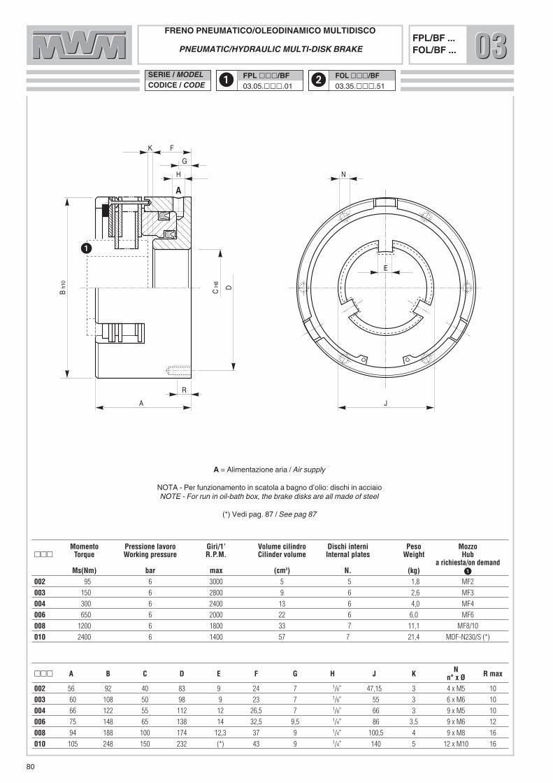
A
B h1
0
F
J
D
H
G
E
R
N
A
C H
8
K
80
��
FRENO PNEUMATICO/OLEODINAMICO MULTIDISCOPNEUMATIC/HYDRAULIC MULTI-DISK BRAKE
SERIE / MODELCODICE / CODE
FPL ���/BF03.05.���.01
FOL ���/BF03.35.���.51
FPL/BF ...FOL/BF ... 030303
A = Alimentazione aria / Air supply
NOTA - Per funzionamento in scatola a bagno d’olio: dischi in acciaioNOTE - For run in oil-bath box, the brake disks are all made of steel
(*) Vedi pag. 87 / See pag 87
Momento Pressione lavoro Giri/1’ Volume cilindro Dischi interni Peso Mozzo��� Torque Working pressure R.P.M. Cilinder volume Internal plates Weight Hub
a richiesta/on demandMs(Nm) bar max (cm3) N. (kg) �
002 95 6 3000 5 5 1,8 MF2
003 150 6 2800 9 6 2,6 MF3
004 300 6 2400 13 6 4,0 MF4
006 650 6 2000 22 6 6,0 MF6
008 1200 6 1800 33 7 11,1 MF8/10
010 2400 6 1400 57 7 21,4 MDF-N230/S (*)
��� A B C D E F G H J K N R maxn° x Ø002 56 92 40 83 9 24 7 1/8” 47,15 3 4 x M5 10
003 60 108 50 98 9 23 7 1/8” 55 3 6 x M6 10
004 66 122 55 112 12 26,5 7 1/8” 66 3 9 x M5 10
006 75 148 65 138 14 32,5 9,5 1/4” 86 3,5 9 x M6 12
008 94 188 100 174 12,3 37 9 1/4” 100,5 4 9 x M8 16
010 105 248 150 232 (*) 43 9 1/4” 140 5 12 x M10 16

81
FRENI PNEUMATICI/OLEODINAMICI MULTIDISCOA PRESSIONE DI MOLLE
I freni a pressione di molle sono realizzati per ottenere il bloccag-gio istantaneo di una macchina o di parte della stessa in caso diemergenza, semplicemente togliendo pressione all’attuatore.Possono essere inoltre utilizzati come freni di stazionamento, inoccasione di arresti macchina programmati o per manutenzione.Questa tipologia di freno, in condizioni di lavoro, viene mantenu-ta innestata da molle elicoidali, che garantiscono la coppia di fre-nata. Il rilascio avviene adducendo aria/olio in pressione al cilindro dilavoro attraverso il foro di alimentazione «A» posto sul diametroesterno dello stesso.Per il funzionamento a secco, questa tipologia di freni si avvaledi un pacco dischi in bronzo/acciaio che di fatto consente di ope-rare in assenza di lubrificazione.Per assicurare la completa apertura del freno, è necessariogarantire la pressione di rilascio indicata. Inoltre, la valvola dicomando, dotata di scarico rapido, deve essere montata il piùvicino possibile al foro di alimentazione posto sul cilindro perpermettere lo svuotamento dell’attuatore con la conseguenteapertura veloce del freno.
MONTAGGIO
Questo tipo di freno viene prodotto in due diverse versioni:– FPL-N/B-BF, FOL-N/B-BF, senza flangia di montaggio;
per questo modello, è necessario predisporre un centraggiopreciso sulla macchina, rispettando le quote indicate nellascheda tecnica. Per il montaggio, prestare particolare atten-zione alla quota “J”, molto importante ai fini di un corretto fun-zionamento del prodotto.
– FPL-N/C-BF, FOL-N/C-BF: in questo caso, la procedura dimontaggio consiste nel predisporre la foratura per fissare laflangia del freno sulla carcassa della macchina o su di un qual-siasi altro supporto fisso mediante bulloni o viti. È importantecentrare correttamente la flangia di fissaggio.
In ambedue i casi occorre poi montare un mozzo fresato (arichiesta) sull’albero rotante. Le fresature del mozzo andrannoad ingaggiare le alette presenti sui dischi interni.Fare riferimento agli esempi di montaggio
SPRING-APPLIED, PNEUMATICALLY/HYDRAULICALLYRELEASED MULTI-DISK BRAKES
Spring-applied brakes are realized to instantaneously lock amachinery or part of it in an emergency, simply cutting off pres-sure supplied to the brake actuator. They also may be used as parking brakes during scheduledstops or for maintenance.
In working conditions, this type of brake is engaged by the actionof thrust springs, which guarantee the nominal braking torque. Releasing of the brake occurs when air/oil under pressure is sup-plied to the working cylinder through the supply bore «A» locatedon the external diameter of the working cylinder itself.For dry applications, this series of multi-disc brakes makes useof a combination of bronze/steel disks that actually allows you towork without lubrication.In order to obtain a complete disengagement of the brake, youmust guarantee the release pressure suggested on this cata-logue; we also suggest to mount the command valve, whichmust be equipped with a blow-off device, as close as possible tothe working cylinder, to quickly and precisely disengage thebrake.
MOUNTING
This brake is made in two variants:– FPL-N/B-BF,FOL-N/B-BF, without mounting flange: forthis model, a precise centering support must be provided,minding the dimensions reported on the technical sheet. Tomount the brake, pay special attention to dimension ”J”, whichis very important to ensure the correct functioning of the prod-uct
– FPL-N/C-BF, FOL-N/C-BF: in this case, mounting procedureconsists in drilling the proper number of threaded holes to fixthe brake mounting flange to the machinery or other fixed sup-port by means of screws or bolts. To center correctly themounting flange upon the machinery is very important.
In both cases you have to mount a milled hub (on demand) to therotating shaft; this hub inserts into the fins of the inner disks.Please, always refer to mounting examples
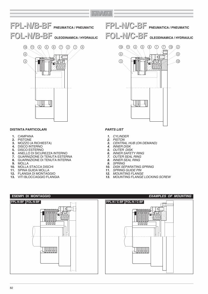
82
DISTINTA PARTICOLARI1. CAMPANA2. PISTONE3. MOZZO (A RICHIESTA)4. DISCO INTERNO5. DISCO ESTERNO6. ANELLO DI SICUREZZA INTERNO7. GUARNIZIONE DI TENUTA ESTERNA8. GUARNIZIONE DI TENUTA INTERNA9. MOLLA
10. MOLLA STACCA DISCHI11. SPINA GUIDA MOLLA12. FLANGIA DI MONTAGGIO13. VITI BLOCCAGGIO FLANGIA
FPL-N/B-BF PNEUMATICA / PNEUMATIC
FOL-N/B-BF OLEODINAMICA / HYDRAULIC
FPL-N/B-BFFOL-N/B-BF
FPL-N/C-BF PNEUMATICA / PNEUMATIC
FOL-N/C-BF OLEODINAMICA / HYDRAULIC
FPL-N/C-BFFOL-N/C-BF
PARTS LIST1. CYLINDER2. PISTON3. CENTRAL HUB (ON DEMAND)4. INNER DISK5. OUTER DISK6. INNER SAFETY RING7. OUTER SEAL RING8. INNER SEAL RING9. SPRING
10. DISK SEPARATING SPRING11. SPRING GUIDE PIN12. MOUNTING FLANGE13. MOUNTING FLANGE LOCKING SCREW
FPL-N-BF FOL-N-BFESEMPI DI MONTAGGIO EXAMPLES OF MOUNTING
FPL-N / C-BF FOL-N / C-BF
6
10 11 4 5 8 7 2
3
1 9
6
10 11 4 5 8 1 7
3
13 2
9
12

A
R
M
DB h8
C H
8
K h8 L
E
N
P
F
H
G
A
J**
��SERIE / MODELCODICE / CODE
FPL-N ��� /B-BF03.40.���.01
FOL-N ��� /B-BF03.70.���.01
FRENO PNEUMATICO/OLEODINAMICOMULTIDISCO A PRESSIONE DI MOLLE
PNEUMATIC/HYDRAULIC SPRING LOADEDMULTI-DISK BRAKES
FPL-N/..B-BFFOL-N/..B-BF 030303
83
��� A B C D E F G H J K L M max N P R maxn° x Ø002 59,5 118 48 92 9 32 24 1/8” 1,5 100 108 33,5 6 x M6 47,15 12
003 67,5 135 57 108 9 32 24 1/8” 1,5 115 125 35,5 6 x M6 55 12
004 73 155 70 118 12 37 26 1/8” 2 135 145 40 8 x M6 66 13
006 92,5 192 87 148 14 42 31,5 1/4” 2 170 181 63 8 x M8 86 16
008 109,5 235 102 188 12,3 50,5 35 1/4” 3 205 220 59 12 x M8 100,5 18
010 116 280 150 248 (*) 58 42 1/4” 3,5 250 265 62 12 x M10 140 20
Momento Pressione di apertura Giri/1’ Volume cilindro Dischi interni Peso Mozzo��� Torque Release pressure R.P.M. Cilinder volume Internal plates Weight Hub
a richiesta/on demandMs(Nm) bar max (cm3) N. (kg) �
002 95 6 3000 14 5 2,7 MF2
003 150 6 2800 18 6 3,7 MF3
004 300 6 2400 35 6 4,9 MF46
006 650 6 2000 41 6 9,5 MF6
008 1200 6 1800 77 6 18.2 MF8/10
010 2400 6 1400 135 7 27,1 MDF-N230/S (*)
A = Alimentazione aria / Air supply
NOTA - Per funzionamento in scatola a bagno d’olio: dischi in acciaioNOTE - For run in oil-bath box, the brke disks are all made of steel
(*) Vedi pag. 87 / See page 87(**) Quota importante per il montaggio / Important dimension for mounting

84
S
QA
DB h8
C H
8
P
N
R
F
H
G
A
K H
7
M
E
L
��SERIE / MODELCODICE / CODE
FPL-N ��� /C-BF03.40.���.02
FOL-N ��� /C-BF03.70.���.02
FRENO PNEUMATICO/OLEODINAMICOMULTIDISCO A PRESSIONE DI MOLLE
PNEUMATIC/HYDRAULIC SPRING LOADEDMULTI-DISK BRAKES
FPL-N/..C-BFFOL-N/..C-BF 030303
��� A B C D E F G H K L M max N P Q R Sn° x Ø002 59,5 118 48 92 9 32 24 1/8” 50 130 33,5 6 x 6,5 142 10 47,15 69,5
003 67,5 135 57 108 9 32 24 1/8” 58 147 35,5 6 x 6,5 159 10 55 77,5
004 73 155 70 118 12 37 26 1/8” 72 168 40 8 x 6,5 184 10 66 83
006 92,5 192 87 148 14 42 31,5 1/4” 89 207 63 8 x 8,5 222 14 86 106,5
008 109,5 235 102 188 12,3 50,5 35 1/4” 110 250 59 12 x 8,5 265 14 100,5 123,5
010 116 280 150 248 (*) 58 42 1/4” 150 298 62 12 x 10,5 316 15,5 140 131,5
Momento Pressione di apertura Giri/1’ Volume cilindro Dischi interni Peso Mozzo��� Torque Release pressure R.P.M. Cilinder volume Internal plates Weight Hub
a richiesta/on demandMs(Nm) bar max (cm3) N. (kg) �
002 95 6 3000 14 5 3,9 MF2
003 150 6 2800 18 6 5,3 MF3
004 300 6 2400 35 6 6,7 MF46
006 650 6 2000 41 6 13,5 MF6
008 1200 6 1800 77 6 23,7 MF8/10
010 2400 6 1400 135 7 35,4 MDF-N230/S (*)
A = Alimentazione aria / Air supply
NOTA - Per funzionamento in scatola a bagno d’olio: dischi in acciaioNOTE - For run in oil-bath box, the brke disks are all made of steel
(*) Vedi pag. 87 / See pag 87
85
414141PARTI ACCESSORIE
ACCESSORIES
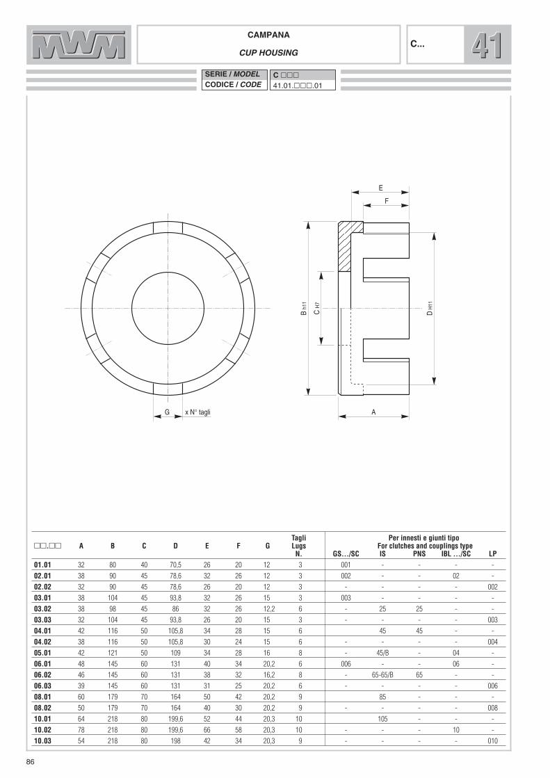
C H
7
AG
D H
11
F
E
B h1
1
x N° tagli
CAMPANACUP HOUSING
C... 414141SERIE / MODELCODICE / CODE
C ���41.01.���.01
86
Tagli Per innesti e giunti tipo��.�� A B C D E F G Lugs For clutches and couplings type
N. GS.../SC IS PNS IBL .../SC LP01.01 32 80 40 70,5 26 20 12 3 001 - - - -
02.01 38 90 45 78,6 32 26 12 3 002 - - 02 -
02.02 32 90 45 78,6 26 20 12 3 - - - - 002
03.01 38 104 45 93,8 32 26 15 3 003 - - - -
03.02 38 98 45 86 32 26 12,2 6 - 25 25 - -
03.03 32 104 45 93,8 26 20 15 3 - - - - 003
04.01 42 116 50 105,8 34 28 15 6 45 45 - -
04.02 38 116 50 105,8 30 24 15 6 - - - - 004
05.01 42 121 50 109 34 28 16 8 - 45/B - 04 -
06.01 48 145 60 131 40 34 20,2 6 006 - - 06 -
06.02 46 145 60 131 38 32 16,2 8 - 65-65/B 65 - -
06.03 39 145 60 131 31 25 20,2 6 - - - - 006
08.01 60 179 70 164 50 42 20,2 9 85 - - -
08.02 50 179 70 164 40 30 20,2 9 - - - - 008
10.01 64 218 80 199,6 52 44 20,3 10 105 - - -
10.02 78 218 80 199,6 66 58 20,3 10 - - - 10 -
10.03 54 218 80 198 42 34 20,3 9 - - - - 010
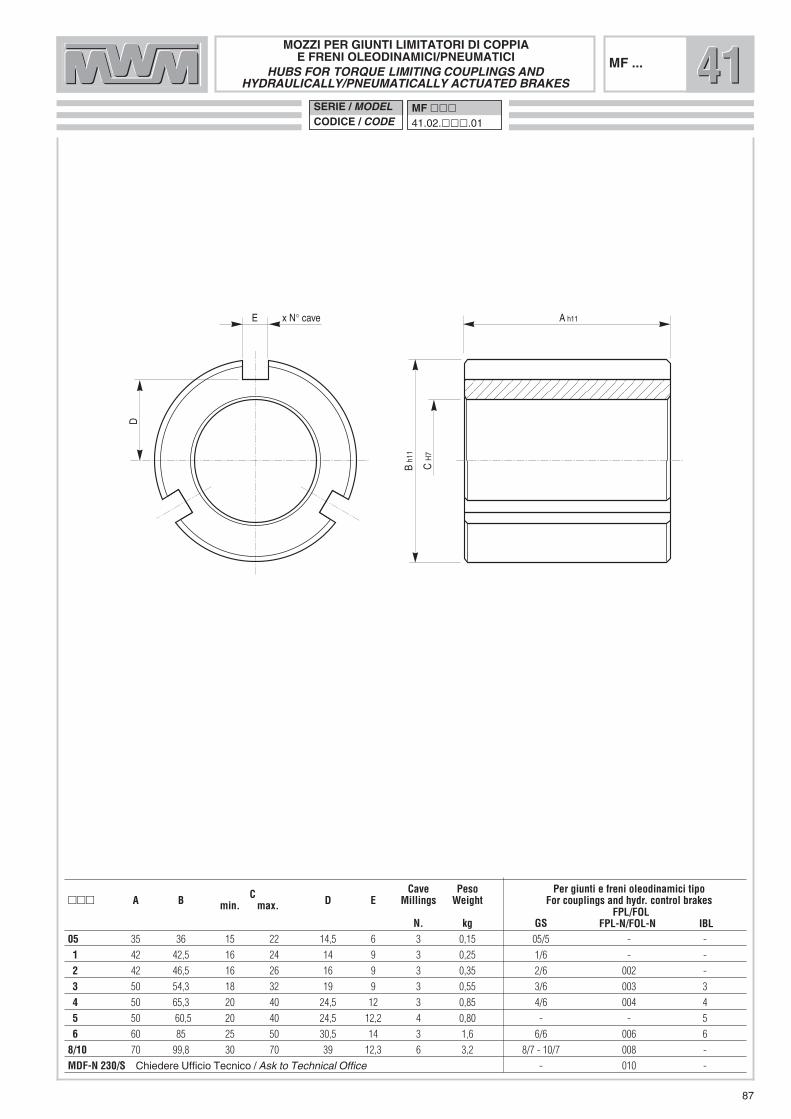
87
C H
7
A h11E
B h1
1
x N° cave
D
MOZZI PER GIUNTI LIMITATORI DI COPPIAE FRENI OLEODINAMICI/PNEUMATICI
HUBS FOR TORQUE LIMITING COUPLINGS ANDHYDRAULICALLY/PNEUMATICALLY ACTUATED BRAKES
MF ...
C Cave Peso Per giunti e freni oleodinamici tipo��� A B min. max. D E Millings Weight For couplings and hydr. control brakes
N. kg GSFPL/FOL
FPL-N/FOL-N IBL05 35 36 15 22 14,5 6 3 0,15 05/5 - -
1 42 42,5 16 24 14 9 3 0,25 1/6 - -
2 42 46,5 16 26 16 9 3 0,35 2/6 002 -
3 50 54,3 18 32 19 9 3 0,55 3/6 003 3
4 50 65,3 20 40 24,5 12 3 0,85 4/6 004 4
5 50 60,5 20 40 24,5 12,2 4 0,80 - - 5
6 60 85 25 50 30,5 14 3 1,6 6/6 006 6
8/10 70 99,8 30 70 39 12,3 6 3,2 8/7 - 10/7 008 -
MDF-N 230/S Chiedere Ufficio Tecnico / Ask to Technical Office - 010 -
SERIE / MODELCODICE / CODE
MF ���41.02.���.01
414141

88

89
MICROINTERRUTTORI E SENSORI
MICROSWITCHES AND SENSORS 515151
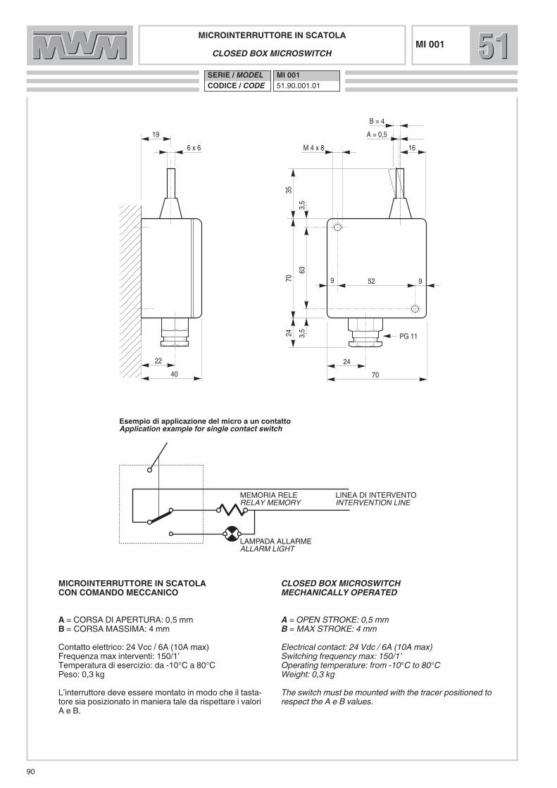
MICROINTERRUTTORE IN SCATOLACLOSED BOX MICROSWITCH
SERIE / MODELCODICE / CODE
MI 00151.90.001.01
90
19
6 x 6
A = 0,5
16M 4 x 8
52 99
24
70
22
40
2470
35
3,5
633,
5
PG 11
B = 4
MEMORIA RELERELAY MEMORY
LINEA DI INTERVENTOINTERVENTION LINE
LAMPADA ALLARMEALLARM LIGHT
Esempio di applicazione del micro a un contattoApplication example for single contact switch
MI 001 515151
CLOSED BOX MICROSWITCH MECHANICALLY OPERATED
A = OPEN STROKE: 0,5 mmB = MAX STROKE: 4 mmElectrical contact: 24 Vdc / 6A (10A max)Switching frequency max: 150/1’Operating temperature: from -10°C to 80°CWeight: 0,3 kgThe switch must be mounted with the tracer positioned torespect the A e B values.
MICROINTERRUTTORE IN SCATOLACON COMANDO MECCANICO
A = CORSA DI APERTURA: 0,5 mmB = CORSA MASSIMA: 4 mmContatto elettrico: 24 Vcc / 6A (10A max)Frequenza max interventi: 150/1’Temperatura di esercizio: da -10°C a 80°CPeso: 0,3 kgL’interruttore deve essere montato in modo che il tasta -tore sia posizionato in maniera tale da rispettare i valoriA e B.

4,8
12,7
3,95 3,950,
6 m
ax8,
1 ±0
,3
8,7 15
,3
Ø 2,35
NCNOCOM
300 mm
5,34,8
12,7
3,95 3,95
19,3
max
8,7 15
,3
Ø 2,35
NCNOCOM
300 mm
5,3
2,2
9,5
21,2
5,85 5,85
0,6
max
8,4
±0,3
9,2
16,9
Ø 2,35
NC
NO
COM
300 mm
6,4
3,2
9,5
21,2
5,85 5,85
19,3
max
9,2
16,9
Ø 2,35
NC
NO
COM
300 mm
6,4
NC (Rosso / Red)
NO (Blu / Blue)
COM (Nero / Black)
Contatti microMicroswitch contacts
��SERIE / MODELCODICE / CODE
MI01051.92.001.01
MI010-R51.92.001.02 � MI020
51.92.002.01 �
� �
� �
MI020-R51.92.002.02
MICROINTERRUTTOREMICROSWITCH
MI010 - /RMI020 - /R
91
Degree of protection: IP 67To obtain other technical information, contact the TechnicalOffice
Grado di protezione: IP 67Per ulteriori informazioni, contattare l’Ufficio Tecnico
515151

��SERIE / MODELCODICE / CODE
SI 001 51.98.001.01
SI 002 51.98.001.02
92
SENSORI INDUTTIVIINDUCTIVE SENSORS
SI 001SI 002 515151
M8x
1
Ø 6
,5
35
28
0,5 - 1,4*
M8x
1
55,50,5 - 1,9*
2000 mm3000 mm
� �
Degree of protection: IP 67* Distances stated above refer to the sensor sensibility onsteel.To obtain other technical information, contact the TechnicalOffice
Grado di protezione: IP 67* Le distanze indicate si riferiscono alla sensibilità delsensore su acciaio.Per ulteriori informazioni, contattare l’Ufficio Tecnico

93
RRRDISCHI FRIZIONE, FRENO E GIUNTI
BRAKE AND CLUTCH DISKS

��
DISCHI ESTERNI PER FRENI, FRIZIONI E GIUNTI
OUTER DISK FOR BRAKES, CLUTCHES AND COUPLINGS
SERIE / MODELCODICE / CODE
DEM ���R311.01.01.���.01
DEM ���/BFR320.01.01.���.01
94
ED x N° alette
C
A
B
DEM...
Alette��� A B C D E* Lugs
N.05 68 57 37 11,85 0,6 3
1 81 70,4 44 11,75 1,5 3
2 89 78,5 48 11,7 1,5 3
2/a 92,5 81,25 48 14,5 1,5 3
3 104,5 93,4 56 14,6 1,5 3
3/b 97 85,65 56 11,85 1,5 6
3/d 100,5 88,45 56 15,6 1,5 6
4 116,25 105,35 67 14,5 1,5 6
4/b 108,75 97,8 67 12,15 1,5 8
5/b 120,35 108,45 67 15,75 1,5 8
5/d 135,5 117,25 67 19,75 1,5 6
6 143,6 130,35 87 19,65 1,5 6
6/b 144,6 129,85 87 16 1,5 8
167 166 148,85 106 12 1,5 8
8 179,5 163,5 102,5 19,85 2 9
10 218,5 198,6 102,5 20 2 10
RRR
* Altri spessori a richiesta / Other thicknesses can be supplied on request
*

DISCHI INTERNI PER FRENI, FRIZIONI E GIUNTI
INNER DISK FOR BRAKES, CLUTCHES AND COUPLINGS
SERIE / MODELCODICE / CODE
DIM ���R331.01.01.���.01
95
E
D x N° alette
C
B
A
DIM...
Alette��� A B C D E* Lugs
N.05 57 37,15 30 5,95 1,5 3
1 69,35 43 29 8,85 1,5 3
2 78,2 47,15 33 8,75 1,5 3
3 92,3 55 39,5 8,7 1,5 3
3/b 84,2 55,25 40 8,8 1,5 3
4 104,25 66 50,25 9,75 1,5 3
4/b 97,35 66 50,25 9,75 1,5 3
4/IBL/b 96,15 61,15 49,75 12,15 1,5 4
4/IS 104,25 66 50,25 11,95 1,5 3
5 115,5 66 48 9,75 1,5 3
6 128,5 86 64 11,75 1,5 3
6/IS 128,5 86 64 13,85 1,5 3
8/IS 160,25 100,5 80,4 11,95 2 6
10 196 100,5 80,4 11,95 2 6
� Altri spessori a richiesta / Other thicknesses can be supplied on request
RRR
* Altri spessori a richiesta / Other thicknesses can be supplied on request
*
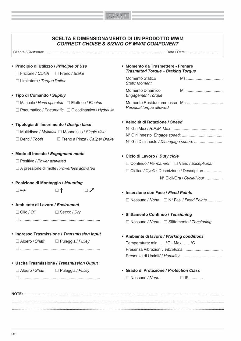
96
• Principio di Utilizzo / Principle of UseFrizione / Clutch Freno / BrakeLimitatore / Torque limiter
• Tipo di Comando / SupplyManuale / Hand operated Elettrico / ElectricPneumatico / Pneumatic Oleodinamico / Hydraulic
• Tipologia di Inserimento / Design baseMultidisco / Multidisc Monodisco / Single discDenti / Tooth Freno a Pinza / Caliper Brake
• Modo di Innesto / Engagment modePositivo / Power activatedA pressione di molle / Powerless activated
• Posizione di Montaggio / Mounting
• Ambiente di Lavoro / EnviromentOlio / Oil Secco / Dry.......................................................................
• Ingresso Trasmissione / Transmission InputAlbero / Shaft Puleggia / Pulley.......................................................................
• Uscita Trasmissione / Transmission OuputAlbero / Shaft Puleggia / Pulley.......................................................................
• Momento da Trasmettere - FrenareTrasmitted Torque – Braking Torque Momento Statico Ms: ...............................Static MomentMomento Dinamico Mi: ................................Engagement TorqueMomento Residuo ammesso Mr: ................................Residual torque allowed
• Velocità di Rotazione / Speed N° Giri Max / R.P.M. Max: ............................................N° Giri Innesto Engage speed: ....................................N° Giri Disinnesto / Disengage speed: .........................
• Ciclo di Lavoro / Duty cicleContinuo / Permanent Vario / Exceptional Ciclico / Cyclic: Descrizione / Description ….......….
N° Cicli/Ora / Cycle/Hour …............
• Inserzione con Fase / Fixed PointsNessuna / None N° Fasi / Fixed Points .............
• Slittamento Continuo / TensioningNessuno / None Slittamento / Tensioning
• Ambiente di lavoro / Working conditionsTemperature: min .…..°C - Max ……°C Presenza Vibrazioni / Vibrations: ..................................Presenza di Umidità/ Humidity: ...................................
• Grado di Protezione / Protection ClassNessuno / None IP ............
SCELTA E DIMENSIONAMENTO DI UN PRODOTTO MWMCORRECT CHOISE & SIZING OF MWM COMPONENT
Cliente / Customer: ....................................................................................................................... Data / Date: ................................
NOTE: .......................................................................................................................................................................................................................................................................................................................................................................................................................................................................................................................................................................................................................................