mwm catalogo 2011 1:mwm catalogo 2011 1 - ringspann.ch · dalla frizione o dal freno a catalogo....
TRANSCRIPT

Schaltbare Kupplungen und Bremsen

6
INTRODUZIONE
Negli innesti, viene fatta distinzione nella trasmissione dellacoppia torcente e cioè: per attrito (frizione), a dentini frontali(innesti).
Le frizioni comandate elettromagneticamente sono in grado diaccoppiare due cinematismi meccanici rotanti con velocitàrelative diverse (accoppiamenti dinamici).
Gli innesti a dentini, possono essere comandati come le frizio-ni, ed anche loro servono a collegare due cinematismi mecca-nici rotanti con velocità sincrona oppure con una minima diffe-renza di velocità.
In tutte quelle applicazioni di frizioni e freni lamellari, dove siprevede un eccessivo lavoro dinamico o elevate frequenze dimanovra, si consiglia il funzionamento con lubrificazione, inmodo da ottenere rapidamente lo smaltimento del calore chepotrebbe prodursi.
Quando, per ragioni di sicurezza, sono necessari interventi inassenza di corrente, possono essere impiegati freni, frizioni edinnesti a pressione di molle, nelle versioni per funzionamento asecco o con lubrificazione.
I freni di blocco a pressione di molle senza gioco, per funziona-mento a secco, soddisfano esigenze di precisione nei posizio-namenti, in particolare sui motori comando, bracci manipolato-ri dei robot, e su viti a circolazione di sfere, per la traslazione diassi su macchine utensili a CNC.
Per garantire il collegamento di due cinematismi in una posizio-ne fissa, si devono usare innesti a dentini con fase.
INTRODUCTION
A distinction is made between the friction-plate type and mesh-ing-tooth type coupling.
Electromagnetically controlled clutches can couple two rotatingmechanical kinematic motion devices with different relativespeeds (dynamic coupling).
In the case of the tooth-type coupling, the relative motion hasto be kept to a minimum.
In all those applications with disk-type clutches and brakes,where excessive dynamic work or high operating frequenciesare involved, it is recommended to use lubrication to rapidlyeliminate any generated heat.
If unexpected electrical power loss is possible, the thrust-springtype of brake, clutch or coupling is recommended, either in thedry or lubricated version.
The dry-operating, zero-play, thrust-spring brakes are very suit-able for precision positioning, particularly with motor-actuatedrobot arms and circulating-ball screws for translational axialmovement on CNC tool machinery.
To assure connection at a precise fixed point between tworotating parts, a tooth-type, phase coupling unit must be used.
SCELTA
Dovendo applicare un freno, una frizione o un innesto debbonoessere tenuti ben presenti i seguenti fattori:
1. Tipo macchina2. Applicazione in scatola chiusa, con lubrificazione o a secco3. Tipo di comando disponibile, a seconda del tipo di macchi-
na o cinematismo4. Spazio a disposizione5. Grandezza di massima della potenza da trasmettere6. Numero degli interventi
La conoscenza dei dati sopra citati permetterà di scegliere iltipo di freno o frizione o innesto più adatto ad assolvere nelmiglior modo alla funzione richiesta.A questo punto si dovrà calcolare la grandezza e per questosarà necessario conoscere i seguenti dati tecnici:
– Tipo motore– Potenza motore in kW– Numero giri/minuto dell’albero freno o frizione o innesto– Numero interventi ora ad intervalli costanti, oppure numero
interventi massimi al minuto e precisione richiesta– Momento d’inerzia J delle masse– Tempi d’accelerazione
SELECTION
In any application involving a brake, clutch or coupling unit, thefollowing important factors must be considered:
1. Type of machine2. If the application is enclosed, with or without lubrication.3. Type of controls available, according to the type of machine
or mechanical action.4. Available space.5. Overall maximum power to be transmitted.6. Number of work phases.
When all these data are obtained, the right type of brake, clutchor coupling unit can be selected. Then, proceeding with the sizecalculation, the following technical data have to be obtained:
– Type of motor– Motor power in kW– R.P.M. of the brake, clutch or coupling unit.– Regular interventions per hour (or maximum interventions per
minute) and degree of required precision.– Moment of inertia J – Acceleration or braking times

7
MOMENTI
Mi = Momento inseribile innesto o freno (a catalogo)Ms = Momento statico (coppia max trasmissibile)Mic = Momento di inserzione (teorico da calcolo)Mt = Momento costante di trasmissione (o coppia) del caricoMa = Momento di accelerazione sotto carico
da 0 a n1 o da n1 a n2 giri
Poichè nella fase di innesto oltre ad accelerare le masse si devetrasmettere il momento costante, si ha:
Perciò l’innesto o il freno dovrà essere proporzionato almomento d’inserzione «Mic».
Mt = Momento da trasmettere
Se applichiamo ad un braccio di leva r una forza F si ha ilmomento Mt
Essendo i moti esclusivamente rotatori, si devono fare entrarenei calcoli i seguenti dati:
N = Potenza in kWn = Numeri in giri/min.
Si ha la nota formula:
Ma = Momento di accelerazione
Il momento di accelerazione si quando la velocità muta neltempo. Accelerazione è il rapporto fra la variazione di velocità e l’inter-vallo di tempo in cui questa avviene.Detto t il tempo di accelerazione in secondi necessario per por-tare le masse alla velocità ω si ha:
MOMENTS
Mi = Engagement coupling or braking moment (per catalog)Ms = Static moment (maximum transmissable couple)Mic = Engagement moment (theoric torque)Mt = Constant transmitted load moment (or couple)Ma = Acceleration moment under load,
0 to n1 or n1 to n2 R.P.M.
Since in addition to accelerating the masses during the cou-pling phase, a constant moment must also be transmitted, wehave:
Therefore, the coupling or brake must be proportioned to theengagement moment, «Mic».
Mt = Transmitted moment
If we apply to a lever r a force F, we have:
Since we only have turning moviments, the factors in the calcu-lations are:
N = Power in kWn = R.P.M.
We so have the well-know formula:
Ma = Acceleration moment
The acceleration moment is produced by a change in velocity.
Acceleration is the ratio between the velocity’s change and theinterval of time duting which this change takes place.If we take «t» as the time interval in seconds required to accel-erate a mass to a velocity, ω, we have:

8
A questo punto si deve fare intervenire nei calcoli il numero digiri al minuto n.
Per calcolare il momento d’inerzia J di corpi rotanti intorno alloro asse si ha:
Il momento d’inerzia per cilindri pieni con diametro esterno D elunghezza L in cm si ottiene con:
v = Peso specifico in g/cm2
m = in kgV = in m/s
Il momento d’inerzia di masse con movimento rettilineo di uncorpo a velocità (V) per mezzo di un albero ruotante alla velo-cità n, è:
Riduzione dei momenti d’inerzia.
Un momento d’inerzia J2 su un albero ruotante alla velocità n2
riferito ad un albero con velocità n1 si ha:
La conoscenza dei dati sopra indicati rende possibile calcolareil momento d’accelerazione Ma da 0 a n1
da n1 a n2 si ha:
Now we have to introduce the rotary speed, R.P.M., indicatedby n.
The formula to calculate the moment of inertia J of a body rotat-ing about its axis is the following:
In the case of a cylinder of diameter D and length L, we have:
v = specific weight in g/cm2
m = mass in kgV = velocity in m/s
The moment of inertia of masses with rectilinear movement of abody at velocity (V) by means of shaft rotating at a velocity (n),is:
Reduction of moments of inertia.
The moment of inertia J2 on a shaft rotating at a velocity n2
respect to a shaft with a velocity n1 is:
Now we can now calculate the moment Ma due to acceleration.From 0 to n1 we have:
From n1 to n2, we have:

9
Riassumendo:
il cui valore non deve mai essere superiore al valore Mi indicatonelle tabelle tecniche per ogni grandezza
Calcolo del tempo di accelerazione o decelerazione:
Da 0 a n1 si ha:
da n1 a n2 si ha:
Mi = Momento inseribile innesto o freno (a catalogo)Mic = Momento dovuto al carico (da calcolo)Mi – Mic per accelerazioneMi + Mic per decelerazione
Se l’innesto avviene a vuoto o con un carico trascurabile si ha:
Essendo a volte difficile conoscere esattamente tutti questidati, è sufficiente determinare la coppia «Mt» con la seguenteformula:
dove: Mt = Momento del carico in (Nm)P = Potenza motore in kWn = Numero giri/min. dell’albe ro innesto o freno
N.B.: Il valore dato da questa formula è un valore nominale eperciò insufficiente a stabilire la grandezza dell’innesto o delfreno. La nostra esperienza ci ha portato a stabilire dei valori dimaggiorazione, in modo da consentire un margine di sicurezza.
Mt di sicurezza = Mt nominale per K.
K = Coefficente di maggiorazione, che varia come segue:
In conclusion:
which value must never exceed the value of Mi indicated intechnical tables.
Calculation of acceleration or deceleration time:
From 0 to n1, we have:
From n1 to n2, we have:
Mi = Engageable coupling or braking moment (per catalog)Mic = Moment due to the load (as calculated)Mi – Mic due to accelerationMi + Mic due to deceleration
If coupling occurs under little or no load, we have:
Sometimes exact values are difficult to obtain, so you can usethis formula in order to determinate the «Mt»:
where: Mt = Moment due to the load (Nm)P = Motor power in kWn = R.P.M. of coupling or brake shaft
NOTE: This formula gives a nominal value, which is insufficientto establish the coupling or brake size. Based on our experi-ence, we have made these values higher to provide an ade-quate safety factor.
Mt with safety factor = Mt nominal value times K.
The different values of the safety factor K are shown in the fol-lowing table.
10
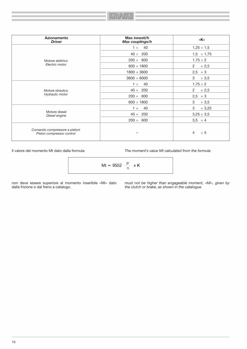
Il valore del momento Mt dato dalla formula:
non deve essere superiore al momento inseribile «Mi» datodalla frizione o dal freno a catalogo.
The moment’s value Mt calculated from the formula:
must not be higher than engageable moment, «Mi», given bythe clutch or brake, as shown in the catalogue.
Azionamento Max innesti/hDriver Max couplings/h «K»
1 ÷ 40 1,25 ÷ 1,5
40 ÷ 200 1,5 ÷ 1,75
200 ÷ 600 1,75 ÷ 2
600 ÷ 1800 2 ÷ 2,5
1800 ÷ 3600 2,5 ÷ 3
3600 ÷ 6000 3 ÷ 3,5
1 ÷ 40 1,75 ÷ 2
40 ÷ 200 2 ÷ 2,5
200 ÷ 600 2,5 ÷ 3
600 ÷ 1800 3 ÷ 3,5
1 ÷ 40 3 ÷ 3,25
40 ÷ 200 3,25 ÷ 3,5
200 ÷ 600 3,5 ÷ 4
– 4 ÷ 5
Motore elettricoElectric motor
Motore idraulicoHydraulic motor
Motore dieselDiesel engine
Comando compressore a pistoniPiston compressor control

11
TABELLA OLII
Per frizioni elettromagnetiche lamellari la tipolgia consigliata è:
DIMENSIONI FORI E CHIAVETTE
Secondo DIN 6885 foglio 2
All’ordinazione specificare sempre:
— Dimensione foro o albero— Dimensione cava per chiavetta (se diversa dalla tabella)
OIL TABLE
For electromagnetic disk-type clutches oil type reccomended is:
HOLE AND KEY DIMENSIONS
According DIN 6885 Sheet 2
With all orders, please specify:
— Hole or shaft dimensions— Key-slot dimensions (if different from as shown in table)
D >10 >12 >17 >22 >30 >38 >44 >50 >58 >65 >75 >85 >95 >110 >130 >150÷12 ÷17 ÷22 ÷30 ÷38 ÷44 ÷50 ÷58 ÷65 ÷75 ÷85 ÷95 ÷110 ÷130 ÷150 ÷170
B 4 5 6 8 10 12 14 16 18 20 22 25 28 32 36 40H 4 5 6 7 8 8 9 10 11 12 14 14 16 18 20 22T1 3 3,8 4,4 5,4 6 6 6,5 7,5 8 8 10 10 11 13 13,7 14T2 1,1 1,3 1,7 1,7 2,1 2,1 2,6 2,6 3,1 4,1 4,1 4,1 5,1 5,2 6,5 8,2
AGIP OTE 32 2,9 °E a 50° CESSO TERESSO 32 3,1 °E a 50° CSHELL TURBO 32 3 °E a 50° CCASTROL PERFECTO 32 2,8 °E a 50° CMOBIL DTE Light 2,9 °E a 50° C
12
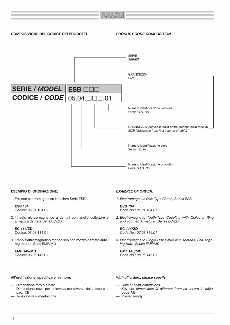
COMPOSIZIONE DEL CODICE DEI PRODOTTI
ESEMPIO DI ORDINAZIONE:
1. Frizione elettromagnetica lamellare Serie ESB
ESB 134Codice: 05.04.134.01
2. Innesto elettromagnetico a dentini con anello collettore earmatura dentata Serie EC/ZD
EC 114/ZDCodice: 07.03.114.01
3. Freno elettromagnetico monodisco con mozzo dentato auto-registrante Serie EMF/MD
EMF 145/MDCodice: 08.05.145.01
All’ordinazione specificare sempre:
— Dimensione foro o albero— Dimensione cava per chiavetta (se diversa dalla tabella a
pag. 13)— Tensione di alimentazione
PRODUCT CODE COMPOSITION
EXAMPLE OF ORDER:
1. Electromagnetic Disk-Type Clutch, Series ESB
ESB 134Code No.: 05.04.134.01
2. Electromagnetic Tooth-Type Coupling with Collector Ringand Toothed Armature, Series EC/ZD
EC 114/ZDCode No.: 07.03.114.01
3. Electromagnetic Single-Disk Brake with Toothed, Self-Align-ing Hub, Series EMF/MD
EMF 145/MDCode No.: 08.05.145.01
With all orders, please specify:
— Hole or shaft dimensions— Key-slot dimensions (if different from as shown in table,
page 13)— Power supply
SERIE / MODELCODICE / CODE
ESB ���05.04.���.01
SERIESERIES
GRANDEZZASIZE
Numero identificazione versioneVersion I.D. No.
GRANDEZZA (ricavabile dalla prima colonna della tabella)SIZE (obtainable from first column of table)
Numero identificazione serieSeries I.D. No.
Numero identificazione prodottoProduct I.D. No.
33
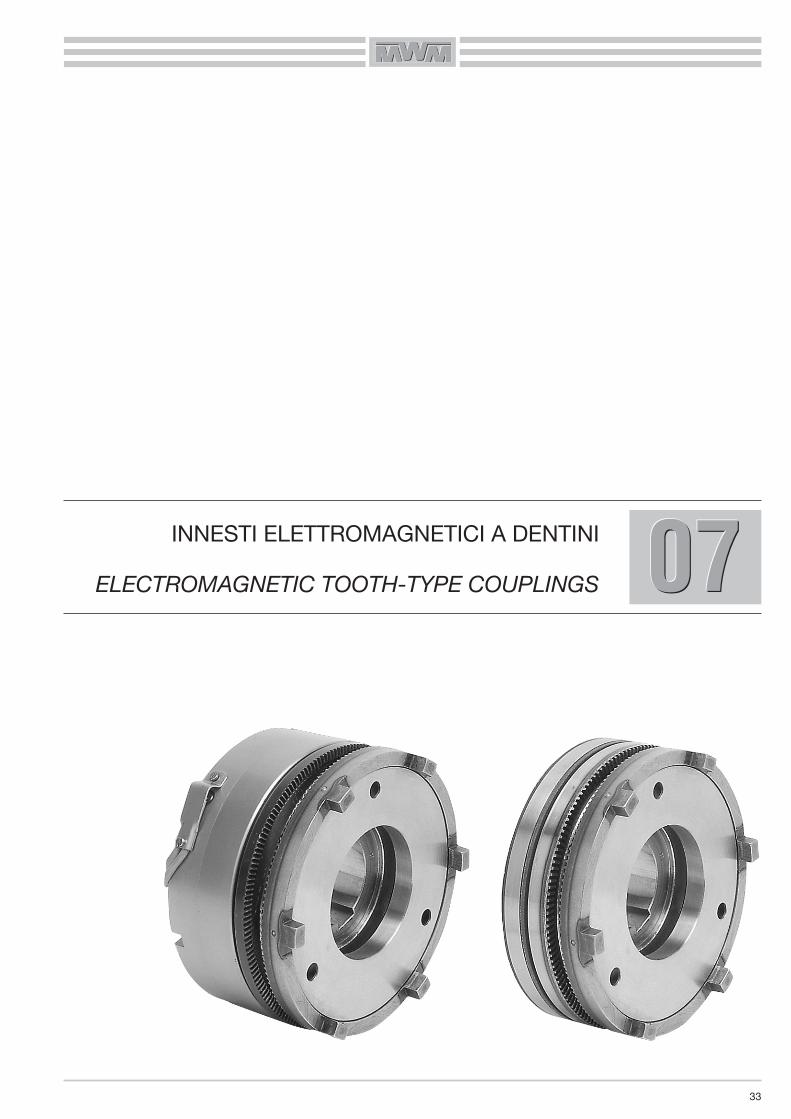
070707INNESTI ELETTROMAGNETICI A DENTINI
ELECTROMAGNETIC TOOTH-TYPE COUPLINGS
34
INNESTI ELETTROMAGNETICI A DENTINI
Questi innesti sono stati realizzati per garantire notevoli coppietrasmissibili con dimensioni contenute.Particolari vantaggi sono la possibilità di funzionare in presenzadi lubrificazione, oppure a secco nonchè l’assenza assoluta ditrascinamento in posizione di folle.
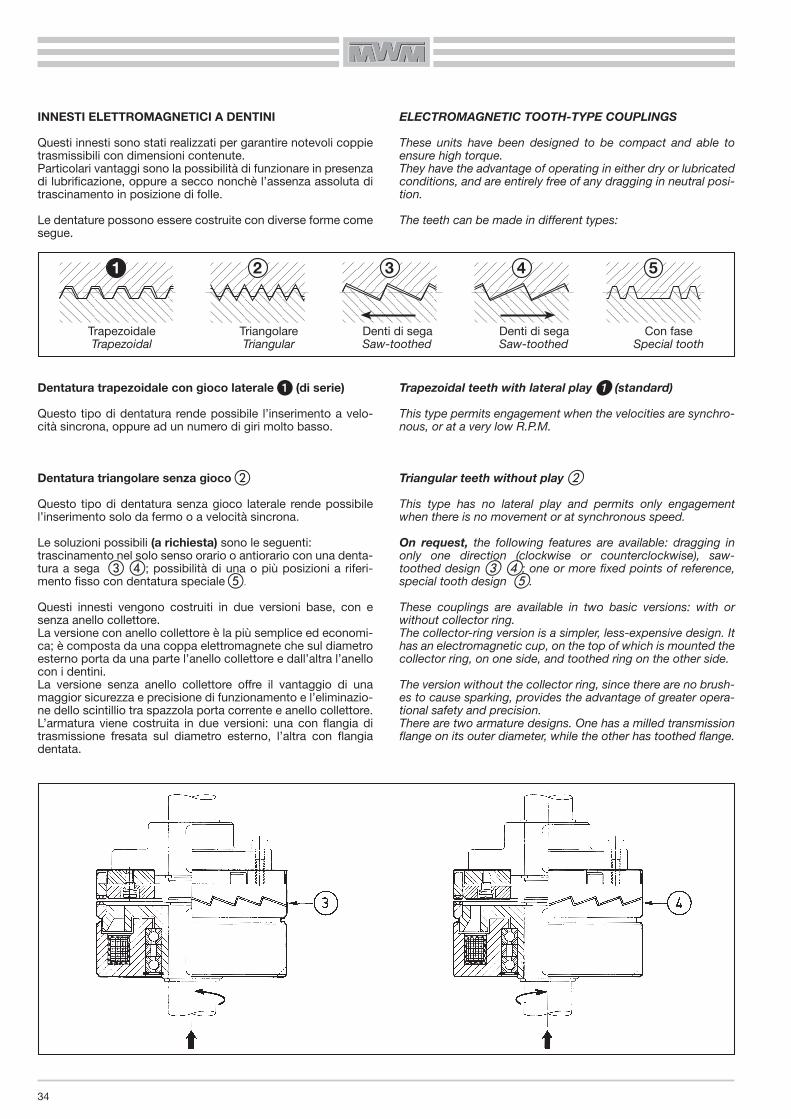
Le dentature possono essere costruite con diverse forme comesegue.
Dentatura trapezoidale con gioco laterale � (di serie)
Questo tipo di dentatura rende possibile l’inserimento a velo-cità sincrona, oppure ad un numero di giri molto basso.
Dentatura triangolare senza gioco �
Questo tipo di dentatura senza gioco laterale rende possibilel’inserimento solo da fermo o a velocità sincrona.
Le soluzioni possibili (a richiesta) sono le seguenti:trascinamento nel solo senso orario o antiorario con una denta-tura a sega � �; possibilità di una o più posizioni a riferi-mento fisso con dentatura speciale �.
Questi innesti vengono costruiti in due versioni base, con esenza anello collettore.La versione con anello collettore è la più semplice ed economi-ca; è composta da una coppa elettromagnete che sul diametroesterno porta da una parte l’anello collettore e dall’altra l’anellocon i dentini.La versione senza anello collettore offre il vantaggio di unamaggior sicurezza e precisione di funzionamento e l’eliminazio-ne dello scintillio tra spazzola porta corrente e anello collettore.L’armatura viene costruita in due versioni: una con flangia ditrasmissione fresata sul diametro esterno, l’altra con flangiadentata.
ELECTROMAGNETIC TOOTH-TYPE COUPLINGS
These units have been designed to be compact and able toensure high torque.They have the advantage of operating in either dry or lubricatedconditions, and are entirely free of any dragging in neutral posi-tion.
The teeth can be made in different types:
Trapezoidal teeth with lateral play � (standard)
This type permits engagement when the velocities are synchro-nous, or at a very low R.P.M.
Triangular teeth without play �
This type has no lateral play and permits only engagementwhen there is no movement or at synchronous speed.
On request, the following features are available: dragging inonly one direction (clockwise or counterclockwise), saw-toothed design � �; one or more fixed points of reference,special tooth design �.
These couplings are available in two basic versions: with orwithout collector ring.The collector-ring version is a simpler, less-expensive design. Ithas an electromagnetic cup, on the top of which is mounted thecollector ring, on one side, and toothed ring on the other side.
The version without the collector ring, since there are no brush-es to cause sparking, provides the advantage of greater opera-tional safety and precision.There are two armature designs. One has a milled transmissionflange on its outer diameter, while the other has toothed flange.
Trapezoidale Triangolare Denti di sega Denti di sega Con fase Trapezoidal Triangular Saw-toothed Saw-toothed Special tooth

35
COMANDO ELETTROMAGNETICO
Gli innesti sono conformi alle NORME VDE 0580.
ALIMENTAZIONE
La tensione di alimentazione è di 24 V cc. -0 +15%.Su richiesta è possibile avere tensioni diverse.
MONTAGGIO E REGOLAZIONE DEL TRAFERRO
Per il montaggio seguire le istruzioni e gli esempi da noi propo-sti.
Negli innesti senza anello collettore tener bene presente chel’elettromagnete deve essere ancorato contro la rotazione, uti-lizzando una delle tre fresature a 120° ricavate sull’elettroma-gnete, evitando in modo assoluto che l’accoppiamento risultirigido o forzato, al fine di non compremettere la durata deicuscinetti radiali di supporto.
• È molto importante nella fase di montaggio controllare atten-tamente il traferro (G) tra i dentini (vedi misura nelle appositetabelle).
ELECTROMAGNETIC CONTROL
The couplings conform to the VDE 0580 NORMS.
POWER SUPPLY
The couplings operate on 24 V DC -0 +15%.On request, different voltages are available.
MOUNTING AND AIR GAP ADJUSTMENT
For mounting, please follow the instructions and examplesgiven.
The electromagnet on the couplings without the collector ringhas to be anchored counter-rotation, using one of the three120° milled spots on the electromagnet. In order to avoid cut-ting down the service life of the radial support bearings, caremust be taken to avoid any rigidity or forcing when making thecoupling.
• During the assembly phase, it is very important to check tosee that the gap between the teeth (G) is as specified in thespecial table.
��� Traferro G Air gapmin. max.
60 0,20 0,30
70 0,20 0,30
82 0,20 0,40
95 0,25 0,45
114 0,30 0,50
134 0,35 0,55
140 0,35 0,55
166 0,40 0,60
195 0,40 0,60
210 0,40 0,70
240 0,40 0,70
260 0,45 0,75
295 0,50 0,80
325 0,55 0,85

REGOLAZIONE DEL TRAFERRO
– Montare l’innesto a dentini.– Innestare la dentatura.– Applicare una forza in direzione F o F1.
Controllare il traferro in 3 punti (120°) conuno spessimetro; il valore deve essere quelloindicato nelle relative tabelle.
AIR GAP ADJUSMENT
– Mount the toothe-type coupling.– The toothing has to be engaged.– Make force in the direction F or F1.
Check the size of the air gap at 3 points(120°) with a thickness gauge; it shoul be asindicated in the relevant tables.
46
DISTINTA PARTICOLARI
1. COPPA MAGNETE2. ARMATURA DENTATA3. CAMPANA DENTATA4. MOZZO DENTATO 5. MOLLA6. BOBINA 7. ANELLO COLLETTORE8. CHIAVETTA 9. ANELLO DI SICUREZZA
10. ANELLO DI SICUREZZA
EC-N/ZEC-N/Z
PARTS LIST
1. MAGNET CUP2. TOOTHED ARMATURE3. TOOTHED COVER4. TOOTHED HUB5. SPRING6. COIL7. COLLECTOR RING8. KEY9. SAFETY RING
10. SAFETY RING
EC-N/Z
ESEMPIO DI MONTAGGIO EXAMPLE OF MOUNTING
5 2 47 10
8
9
36
1
F F1
*
*
*

INNESTI A DENTINI A PRESSIONE DI MOLLE
TOOTHE-TYPE SPRING LOADED COUPLINGSEC-N .../Z
��� A B C D E F G H J K L M N P Q R S Tmax n° x Ø n° x Ø max n° x Ø082 82 40 18 46 56 65 82 54 4xM5 4x4,5 2 40 8 0,8 2 47 2x 4 6090 90 46 25 53 64 75 92 54 4xM4 4x5,5 2 31,5 10 0,9 2 40 2x 5 6105 105 52 28 65 75 85 105 62 4xM5 4x5,5 2 36 10 0,9 2 44 2x 5 6115 115 58 32 70 85 100 114 68 4xM6 4x6,5 2,5 38,5 12 1 2 50 2x 6 6125 125 62 35 75 90 105 125 72 4xM6 4x6,5 2,5 44,5 12 1 2,5 58 2x 8 6140 140 70 42 85 100 115 140 80 4xM6 4x6,5 2,5 54,5 15 1,1 2,5 67 3x 8 7160 166 78 45 95 115 130 165 90 4xM8 6x8,5 3 59 15 1,2 3 75 3x 8 8185 185 84 50 115 135 155 185 106 6xM8 6x8,5 3 68 15 1,2 3 85 3x10 8215 210 96 60 130 155 180 215 124 6xM8 6x8,5 3 81 15 1,4 4 100 3x10 8
Momento Giri/1’ Spinta assiale sulla corona dentata Peso��� Torque R.P.M. limit WATT Axial thrust on the crown ring Weight
Ms (Nm) max 20° 120° daN kg082 25 4500 30 18 22 1,8090 35 4500 38 26 30 2105 70 4000 45 33 51 2,7115 100 3500 50 37 67 3,5125 160 3300 65 46 100 4,4140 250 3000 85 64 140 6,3160 400 2500 96 68 190 9185 650 2200 115 81 270 14215 1050 2000 135 95 370 20
SERIE / MODELCODICE / CODE
EC-N ���/Z07.50.���.01
47
070707
* P = Regolazione traferro (vedi pag. 46) - Air gap adjustment (see page 46)

48
DISTINTA PARTICOLARI
1. COPPA MAGNETE2. ARMATURA DENTATA3. ROTORE4. CAMPANA DENTATA5. MOZZO6. ANELLI DISTANZIALI7. ANELLO DI SICUREZZA8. ANELLO DI SICUREZZA9. ANELLO DI SICUREZZA
10. CHIAVETTA DI FERMO11.12.
ESB-N/ZESB-N/Z
PARTS LIST
1. MAGNET CUP2. TOOTHED ARMATURE3. ROTOR4. TOOTHED CUP HOUSING5. HUB6. SPACER RINGS7. SAFETY RING8. SAFETY RING9. SAFETY RING
10. LOCK KEY11.12.
ESB-N/Z
ESEMPIO DI MONTAGGIO EXAMPLE OF MOUNTING
12 10 3 9
4
1
7
112
6
5
8
13
REGOLAZIONE DEL TRAFERRO
– Montare l’innesto a dentini.– Innestare la dentatura.– Applicare una forza in direzione F o F1.
Controllare il traferro * in 3 punti (120°) conuno spessimetro; il valore deve essere quelloindicato nelle relative tabelle.
AIR GAP ADJUSMENT
– Mount the toothe-type coupling.– The toothing has to be engaged.– Make force in the direction F or F1.
Check the size of the air gap * at 3 points(120°) with a thickness gauge; it shoul be asindicated in the relevant tables.
F F1
*
13. BOBINA 13. COILMOLLACUSCINETTI
SPRINGBEARINGS

49
INNESTI A DENTINI A PRESSIONE DI MOLLE
TOOTHE-TYPE SPRING LOADED COUPLINGSESB-N .../Z
��� A C D E F G H J K L M N Qmin. max n° x Ø min. max090 100 58 16 30 51 20 5 0,8 1 4 x M 6 68 40 58 10 4105 114 63 20 38 55 21 6 0,9 1 4 x M 6 82 40 70 10 4115 125 65 20 42 57 23 6 1 1 6 x M 6 92 50 80 10 4140 154 80 25 55 71 25 7 1,1 1 6 x M 8 110 65 95 10 5185 205 100 30 75 90 30 8 1,2 1 6 x M10 148 100 130 10 6215 245 145 40 80 130 48 12 1,4 15 6 x M12 175 110 153 12 7265 290 165 55 95 160 55 15 1,8 15 12 x M12 240 215 16 8320 350 200 75 110 196 65 20 2 22 12 x M14 290 260 18 10385 425 245 90 130 240 78 25 2,5 27 12 x M16 355 315 20 12
Momento Giri/1’ WATT Spinta assiale sulla corona dentata Peso��� Torque R.P.M. limit Axial thrust on the crown ring Weight
Ms (Nm) max. 20° 120° daN kg090 50 4300 50 36 30 2,5105 100 3600 78 58 45 3,5115 200 3300 84 61 65 4,3140 400 2700 135 95 115 8185 800 2100 150 110 180 18215 1600 1800 175 128 330 33,5265 3200 1450 280 205 900 55320 6400 1200 400 310 1500 98385 12800 1000 540 430 2200 178
070707SERIE / MODELCODICE / CODE
ESB-N ���/Z07.80.���.01
* H = Regolazione traferro (vedi pag. 48) - Air gap adjustment (see page 48)

50
DISTINTA PARTICOLARI
1. COPPA MAGNETE2. ARMATURA DENTATA3. ROTORE4. RINVIO5. MOZZO6. BOBINA7. ANELLI DI SICUREZZA ESTERNI8. ANELLI DI SICUREZZA INTERNI9. ANELLI DISTANZIATORI
10. CHIAVETTA DI FERMO11. CUSCINETTI INNESTO12. CUSCINETTI RINVIO13. MOLLA14. GIUNTO ELASTICO
ESBR-N/ZESBR-N/Z
PARTS LIST
1. MAGNET CUP2. TOOTHED ARMATURE3. ROTOR4. TRANSMISSION HUB5. HUB6. COIL7. OUTER SAFETY RING8. INNER SAFETY RING9. SPACER RINGS
10. LOCK KEY11. COUPLING BEARINGS12. TRANSMISSION BEARINGS13. SPRING14. FLEXIBLE COUPLING
ESBR-N/Z
ESEMPI DI MONTAGGIO EXAMPLES OF MOUNTING
ESBG-N/Z
13 10 3 14 112 6
5
98
12
9
7
8
ESBG-N/ZESBG-N/Z13 10 39 14 112
5
9
8129
7
9
14
6 8
F h8 HC H7B
G
D
P
K L
A
M
45°
500 mm
E B
N
Q
J
30° 30°
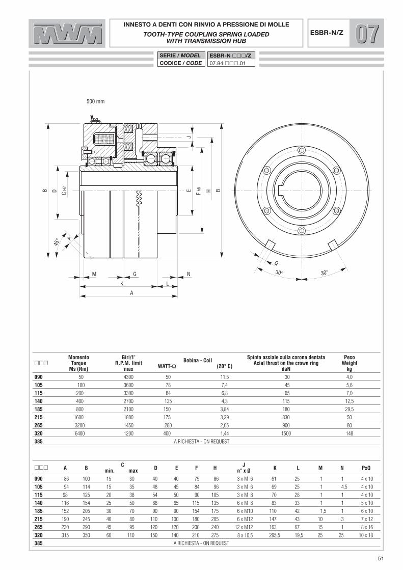
INNESTO A DENTI CON RINVIO A PRESSIONE DI MOLLE
TOOTH-TYPE COUPLING SPRING LOADEDWITH TRANSMISSION HUB
ESBR-N/Z
��� A B C D E F H J K L M N PxQmin. max n° x Ø090 86 100 15 30 40 40 75 86 3 x M 6 61 25 1 1 4 x 10105 94 114 15 35 48 45 84 96 3 x M 6 69 25 1 4,5 4 x 10115 98 125 20 38 54 50 90 105 3 x M 8 70 28 1 1 4 x 10140 116 154 25 50 68 65 115 135 6 x M 8 83 33 1 1 5 x 10185 152 205 30 70 90 90 154 175 6 x M10 110 42 1,5 1 6 x 10215 190 245 40 80 110 100 180 205 6 x M12 147 43 10 3 7 x 12265 230 290 45 95 120 120 200 240 12 x M12 163 67 15 1 8 x 16320 315 350 60 110 150 140 210 275 295,5 19,5 25 25 10 x 18385
Momento Giri/1’ Spinta assiale sulla corona dentata Peso��� Torque R.P.M. limit Bobina - Coil Axial thrust on the crown ring Weight
Ms (Nm) max WATT-Ω (20° C) daN kg090 50 4300 50 11,5 30 4,0105 100 3600 78 7,4 45 5,6115 200 3300 84 6,8 65 7,0140 400 2700 135 4,3 115 12,5185 800 2100 150 3,84 180 29,5215 1600 1800 175 3,29 330 50265 3200 1450 280 2,05 900 80320 6400 1200 400 1,44 1500 148385
SERIE / MODELCODICE / CODE
ESBR-N ���/Z07.84.���.01
51
070707
A RICHI TA - ON REQUESTES
A RICHI TA - ON REQUESTES
x 10,58

HF
Giunto elastico - Serie “A” - Grandezza “W”Flexible coupling - Series “A” - Size “W”
C H7B
G
D
K L M
A
X
α
Y
γ
J
45°
500 mm
E H7
P x Q
INNESTO A DENTI CON GIUNTO A PRESSIONE DI MOLLE
TOOTH-TYPE COUPLING SPRING LOADED WITH FLEXIBLE COUPLING
ESBG-N/Z
��� A B C D E F H J K L M PxQ X Y α γmin. max min. max090 120 100 15 30 40 15 30 45 100 1 86 4 30 4 x 10 2 1,5 3° 17°105 140 114 20 35 55 15 38 60 120 1 94 4 42 4 x 10 4 2 3° 14°115 154 125 20 38 54 15 48 70 150 1 98 6 50 4 x 10 5 2 3° 14°140 190 154 25 50 68 20 65 100 200 1 116 8 66 5 x 10 5 2 2° 14°185 226 205 30 70 90 25 65 100 200 1 152 8 66 6 x 10 5 2 3° 7,5°215 278 245 40 80 110 30 83 125 260 10 190 8 80 7 x 12 5 2 3° 14°265 339 290 45 95 120 40 100 145 275 15 225 14,5 82 10 x 18 Vedi scheda tecnica/See technical sheet320 480 350 50 110 150 50 100 145 275 25 315 23 142 20 x 12 Vedi scheda tecnica/See technical sheet385
Momento Giri/1’ Spinta assiale su dentatura Grandezza giunto Peso ��� Torque R.P.M. Axial force on teeth Bobina - Coil Coupling size Weight
Ms (Nm) max daN WATT-Ω (20° C) W kg090 50 4300 30 50 11,5 4 5,8105 100 3600 45 78 7,4 8 7,5115 200 3300 65 84 6,8 16 10140 400 2700 115 135 4,3 30 19185 800 2100 180 150 3,84 50 37215 1600 1800 330 175 3,29 90 93265 3200 1450 900 280 2,05 8,0 12320 6400 1200 400 1,44 8,0 22385
SERIE / MODELCODICE / CODE
ESBG-N ���/Z07.86.���.01
52
070707
A RICHI TA - ON REQUESTES
A RICHI TA - ON REQUESTES
1 050

��
PORTASPAZZOLE PER FRIZIONI ELETTROMAGNETICHE LAMELLARI
BRUSH HOLDERS FOR MULTIDISCS ELECTROMAGNETIC CLUTCHES
KO...KS...
PORTASPAZZOLA PER FUNZIONAMENTO A SECCOBRUSH HOLDER FOR DRY RUNNING
C E HL Peso Corrente
��� A B D F G J K esagono M N P Weight Currentmax. min. min. hexagon kg Amp maxF 555 KS/06 57 44 27 41 13 14 12 1 8 35 19 6 — M16x1,5 0,05 3F 556 KS/06 68 48 38 45 20 18 19 1 8 35 22 6 — M18 x1,5 0,06 3F 560 KS/08 78 56 46 53 22 24 20 2 14 35 22 8 — M18 x1,5 0,06 5
PORTASPAZZOLA PER FUNZIONAMENTO IN BAGNO D’OLIOBRUSH HOLDER FOR WET RUNNING
C E HL Peso Corrente
��� A B D F G J K esagono M N P Weight Currentmax. min. min. hexagon kg Amp maxF 554 K0/14 60,5 46 24 43 14,5 9,5 11,5 3 7,5 35 17 4 6 M14x1,5 0,04 0,5F 555 K0/14 59 45 34 42 14 20 11 3 8 35 19 4 6 M16x1,5 0,05 1,5F 556 K0/22 78 56 45 52 22 23 20 2 14 35 22 4,5 8 M18x1,5 0,06 2,5
SERIE / MODELCODICE / CODE
KO ���45.01.F���
KS ���45.02.F���
116
�
�
454545