mutnovsky geothermal power complex in kamchatka
TRANSCRIPT
MUTNOVSKY GEOTHERMALPOWER COMPLEX IN KAMCHATKA
*Britvin O.V., *Povarov O.A., **Klochkov E.F., ***Tomarov G.V., **Luzin V.E.
* SC “Geotherm”, p/b 60, E-250 Moscow, 111250 Russia, tel.: (7-095) 918-1561, Fax: (7-095) 918-1560,E-mail: [email protected];
** SC “Geotherm”, 50 Stepnaya st., Petropavlovsk-Kamchatsky, 683008 Russia, tel.: (7-41500) 76-033,Fax: (7-41500) 76-043; E-mail: [email protected];
*** SC “Geotherm-M”, p/b 60, E-250 Moscow, 111250 Russia, tel.: (7-095) 918-1996, Fax: (7-095) 918-1560; E-mail: [email protected];
Key Words: Kamchatka, Mutnovsky, combined cycle, binary
1. INTRODUCTION
Modern development of energy in Russia is characterised by anabrupt increase in requirements for fuel and materials, andcorrespondingly electric power.
The greatest increased cost of energy takes place in remotearea of the Far East, Kamchatka and the Kurils Islands, whichuse mostly imported fuel. Recently the cost of 1 kWh ofelectric power in these areas exceeds world prices and reaches0.1-0.25 dollars USA for 1 kW/h.
Russia has a unique reserve of geothermal energy inKamchatka. This region may secure itself with energyindependence by generating energy at the warm Earth’sexpense.
Russia has a rich experience in mastering geothermal resourceswith many explored Russian geothermal fields. There areabout 1000 drilled geothermal wells within Russia. Today inEurope and throughout the world the intensive utilisation ofnon-traditional renewable types of energy is observed. Inparticular, the use of geothermal energy in Russia is part of astrategic plan of moving whole regions to securing themcheaper and ecologically clean geothermal energy. This plan isbeing realised for the first time in Kamchatka.
2. GEOTHERMAL RESOURCES IN MUTNOVSKOYEThe volcanic regions of Kamchatka have various types ofgeothermal resources. An available potential of the high-temperature (more than 150°C) geothermal fields inKamchatka area totals about 1130 MWe and potential of low-temperature fields (temperature lower 150°C) equals 1345MWt for a period of 100 years [1,2]. Currently, more than 20geothermal fields in Kamchatka have been explored.
The Mutnovsky geothermal field is the most significant amongthe well-studied ones. Mutnovsky reserves were estimated andmeasured in 1988 and 1990, and now the field is completelyready for industrial use.
The Mutnovskoye site is located 70km Southwest fromPetropavlovsk-Kamchatsky. About 60 wells have been drilledat this site, and one third of them are production wells.Reserves of geothermal fluids are capable to drive geothermalpower plants with capacity of more than 250 MW.
Geothermal production from the Mutnovskoye site is both dryand wet steam with temperature up to 240°C and enthalpy upto 660 kcal/kg. Chemical composition of Mutnovskoye
steam/water thermal sources is characterised as chloride,chloride-sulphate, and sulphate-chloride anions with the maincations being sodium and calcium [3].Gas composition of the noncondensibles mainly consists ofcarbonic acid (up to 70% vol. CO2). In addition, there ishydrogen sulphide, nitrogen, oxygen, methane, and hydrogen.Volume content of hydrogen sulphide is 10% on average.
3. UTILIZATION EXPERIENCE OF GEOTHERMALRESOURCES IN KAMCHATKA
The first power generation experience on a base of geothermalresources was in the Paratunsky geothermal field, Kamchatka,Russia, in 1967, where the first of the experimental binarypower plants, with capacity of about 600 kW was constructed[4].
The first industrial geothermal power plant in Russia was alsoconstructed in 1967 in the Pauzetsky field, Kamchatka. Theinstalled capacity of the first phase of the plant was 5 MW.After installation of the second phase of the plant in 1982, thetotal capacity was increased up to 11 MW [5]. Anexperimental back-pressure turbine was installed in theMutnovsky field in 1987, and it produced about 300 kW ofelectricity.The low-temperature geothermal resources are mainly used fordistrict heating and health resorts (Paratunka, Esso, Anagvai)as well for greenhouses (Termalny, Ozernoye), and for fishfarming (Malki, Paratunka).Recently, in Russia, there is an active development ofgeothermal energy utilisation, which is realised within theframes of RF Ministry of Science projects (Department ofScience of Russia), in a structure of GNTPR “Environmentallypure power” [5].
4. VERKHNE-MUTNOVSKY GEOTHERMALPOWER PLANT
More recently, in order to solve energy problems usinggeothermal resources of the Mutnovsky deposit in Kamchatka,“Geotherm” SC with participation of RAO “UES of Russia”,Kamchatka Administration, “Kamchatskenergo” SC, and“Nauka” SC was founded [1,7].
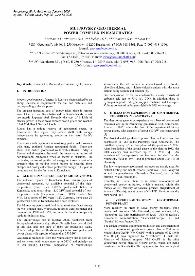
The design, creation, equipment production and construction ofthe first multi-module geothermal power plant – Verkhne –Mutnovskaya GeoPP (VM GeoPP) with a capacity of 12 (3x4)MW (Fig.1) was organised by “Geotherm” SC with RFMinistry of Science support. VM GeoPP is the pilotgeothermal power plant of GeoPP series, which are beingconstructed in Kamchatka. The equipment for this power plant
3139
has been manufactured at “Kaluga Turbine Works” SC (“KTZ”SC), “Podolsky Mashinostroitelny Plant” SC, etc. [8]
The creation of VM GeoPP was based on new approaches topower plant construction:
1. Modular steam preparation system manufacturedcompletely assembled was introduced.
2. GeoPP, also modular (Fig. 1) with 100% factory assemblyof major units-modules (turbogenerators, electrotechnicalequipment, main control panel and etc.) was introduced.
3. Ecologically clean cycle of geothermal fluid utilisationwith an air condenser that prevents direct contact of theworking medium with the environment was incorporated.
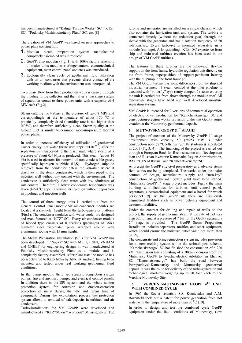
Two phase flow from three production wells is carried throughthe pipeline to the collector and then after a two stage systemof separation comes to three power units with a capacity of 4MW each (Fig.2)
Steam entering the turbine at the pressure of p0=0.8 MPa andcorrespondingly at the temperature of about 170 0C ispractically completely dried (humidity rate is not higher than0.05%) and therefore sufficiently clean. Steam quality at theturbine inlet is similar to common, medium-pressure thermalpower plants.
In order to increase efficiency of utilisation of geothermalcarrier energy, hot water (brine with appr. t=170 0C) after theseparators is transported to the flash unit, where steam at apressure of about 0.4 Mpa is produced. This steam (about 10t/h) is used in ejectors for removal of non-condensable gases,specifically hydrogen sulphide (H2S). Hydrogen sulphideremoved from the condenser enters the adsorber where itdissolves in the steam condensate, which is then piped to theinjection well without any contact with the environment. Thecondensate is sufficiently clean water with low admixture ofsalt content. Therefore, a lower condensate temperature wastaken (t=50 0C appr.) allowing its injection without depositionin pipelines and injection wells.
The control of three energy units is carried out from theGeneral Control Panel module.Six air condenser modules arelocated at a six-meter height from the turbo-generator platform(Fig.1). The condenser modules with water-cooler are designedand manufactured at “KTZ” SC. Every air condenser moduleof hipped type consists of 8 sections (packages) of 38X3diameter steel zinc-plated pipes wrapped around withaluminium ribbing with 15 mm height.
The Steam Preparation Installation (SPI) for VM GeoPP hasbeen developed in “Nauka” SC with MPEI, ENIN, VNIIAMand CNIIEP for engineering design. It was manufactured atPodolsky Mashinostroitelny Plant as a module, and iscompletely factory assembled. After plant tests the module hasbeen delivered to Kamchatka by AN-124 airplane, having beenmounted and tested under real working geothermal fluidconditions.
In the pump module there are separate reinjection systempumps, fire and auxiliary pumps, and electrical control panels.In addition there is the SPI system and the whole stationprotection system for corrosion and erosion-corrosionprotection of metal during the idle and repair time ofequipment. During the exploitation process the protectionsystem allows to removal of salt deposits in turbines and aircondensers.Turbo-installations for VM GeoPP were developed andmanufactured at “KTZ”SC on “Geotherm” SC assignment. The
turbine and generator are installed on a single chassis, whichalso contains the lubrication tank and system. The turbine isconnected directly (without the reduction gear) through thesleeve with the generator and has a rotation frequency of 50rotations/sec. Every turbo-set is mounted separately in amodule (carriage). A longstanding “KTZ” SC experience fromship and industrial turbines creation has been used in thedesign of VM GeoPP turbines.
The features of these turbines are the following: flexiblesupport on the front frame, hydraulic regulation unit directly onthe front frame, superposition of support-persistent bearingwith the oil pump in the front frame [6].The VM GeoPP turbine has some differences from the ship andindustrial turbines: 1) steam control at the inlet pipeline isexecuted with “butterfly” type rotary damper, 2) steam enteringthe unit is carried out from above through the module roof. Allten-turbine stages have band and well developed moistureseparation system.
VM GeoPP is intended for 2 versions of commercial operationof electric power production for “Kamchatskenergo” SC andconstruction-erection works provision under the GeoPP seriescreation at the Mutnovsky geothermal deposit.
5. MUTNOVSKY GEOPP (1ST STAGE)The project of creation of the Mutnovsky GeoPP 1st stagedevelopment with capacity 50 (2x25) MW is underconstruction now by “Geotherm” SC. Its start–up is scheduledin 2001 (Fig.3, 4). The financing of the project is carried outthrough a European Bank for Reconstruction and Developmentloan and Russian investors: Kamchatka Region Administration,RAO “UES of Russia” and “Kamchatskenergo”SC.
At present the GeoPP site civil preparatory and advance steamfield works are being completed. The works under the majorcontract of design, manufacture, supply and “turn-key”construction of geothermal power plant have been started.Mutnovsky GeoPP 1st stage project includes (Fig.5): the mainbuilding with facilities for turbines, unit control panel,separators, electrotechnical equipment and a hostel for watchpersonnel [9]. At the GeoPP site there are also civil-engineered facilities such as power delivery equipment andtreatment facilities.
Under the contract for drilling and repair of wells on theproject, the supply of geothermal steam at the rate of not lessthan 320 t/h and at a pressure of 7 bar for the GeoPP separators2nd stage is provided. The GeoPP Steam PreparationInstallation includes separators, muffler, and other equipment,which should ensure the moisture outlet value not more than0.05%.The condensate and brine reinjection system includes provisionfor a snow melting system within the technological scheme.“Kamchatskenergo” SC has finished the construction of a 220kV transmission line consisting of a 70km extension from theMutnovsky GeoPP to Avacha electric substation in Elizovo.SC “Kamchatskenergo” has built the road betweenPetropavlovsk-Kamchatsky and Mutnovsky geothermaldeposit. It was the route for delivery of the turbo-generator andtechnological modules weighing up to 50 tone each to theVerchne-Mutnovsky Site.
6. VERCHNE-MUTNOVSKY GEOPP 4TH UNITWITH COMBINED CYCLE
In 1965 the Soviet scientists S.S. Kutateladze and A.M.Rozenfeld took out a patent for power generation from hotwater with the temperature of more than 80 0C [10].In order to design and test the combined cycle GeoPPequipment under the field conditions of Mutnovsky, (low
3140
temperatures, high snowfall up to 12 m, frequent and strongwind, and seismicity factor of 9 according to the MSK-64scale), “Geotherm” SC started the work on the 4th unit for theVerchnye-Mutnovsky GeoPP. The combined cycle 4th unitconstruction is now being commissioned [11].From the existing wells surplus two-phase fluid not used by thefirst three power units will be transported to the 4th power unitof Verchnye-Mutnovsky GeoPP. At the upper part of the cyclea modular back-pressure steam turbine with the capacity of 3MW will be used. Such turbines are manufactured by "KalugaTurbine Works" SC.Geothermal two phase fluid (steam-water mixture) passes twostages of separation. Separated steam is transported to thesteam turbine. Wet steam exiting the turbine condenses andcondensate additionally cools in condenser-evaporator tubes.Exhaust pressure of the steam turbine is within the range of0.11-0.03 MPa; i.e. a back-pressure turbine is used.
The scheme of a combined power unit providing GeoPPoperation during wintertime was developed and patented(Fig.6) [11]. Turbines, generators, and heat exchangeequipment are mounted on a five-meter high platform and areenclosed for protection from snow. The panels of the aircondenser are outward inclined preventing snow collection andicing of heat transfer surfaces. Exhaust fans and drivingelectomotors will be located in the flow of already preheatedair. Electrotechnical equipment and devices of automatedcontrol system will be located in a heated enclosure.Total capacity of the power unit will be 9 MW. The binaryinstallation will be designed, constructed and tested undernominal capacity of 6.8 MW, as a pilot model of serial binarypower modules. These power modules will be used in futurecombined power units of the second stage of MutnovskyGeoPP, and for the extensive application of binary GeoPP withthe capacity of 6 and 12 MW for other new projects.
Under design, construction and testing of the combined powerunits several scientific-technical problems are addressed.These include: selection of optimal low-boiling medium,determination of the minimal temperature of brine cooling toprevent silica depositions, optimal method of non-condensablegases disposal from the condenser-evaporator and finally,taking into account the necessity of meeting the environmentalrequirements for hydrogen sulphide disposal.The climatic conditions of the Mutnovsky area are ratherunique due to the location in a northern region at a substantialelevation above the sea level. The average annual airtemperature is -1.5 0C. The average temperature over theduration of eight months (from October till May) is lower at -50C. This low ambient temperature allows reducing the designcondensate temperature in the power cycle to 10-20 0C yieldingconsiderable power output increase (by 20-40%) compared toGeoPP located in hot or moderate climate.
Another advantage of low condensate temperature is that onlya minimal reduction of a power plant output would result fromany future decline of wellhead pressure of production wells.Utilisation of only turbines using geothermal steam is notprofitable because of the required considerable steam flowrates and the height of blades of last turbine stages. There isalso considerable power expense for gas removal from thecondenser under pressure of water saturation corresponding thetemperature of 10-20 0C. Application of a combined cycleeliminates these imperfections.
The working medium of the binary power unit has a lowfreezing temperature that ensures normal operation inwintertime and prevents freezing under emergency stops.
7. COMBINED POWER UNITS FORMUTNOVSKY GEOPP 2ND STAGE
In accordance with the Geothermal Energy DevelopmentProgram in Kamchatka [12] the next phase implementation –(2X30) 60.0 MW Mutnovsky GeoPP 2nd stage has alreadybegun. The construction of a 3rd stage with a capacity of up to100 MW is also planned.
Planning for 2nd and 3rd stage expansions became a mostimportant matter since the Mutnovsky deposit reserves are wellstudied and sufficient, the road and transmission line areavailable, and with the experimental-industrial Verchne-Mutnovskaya GeoPP in operation, electrical power is availableto the GeoPP construction sites during these expansion stages.As to the preliminary data, Mutnovsky GeoPP 2nd stage willconsist of two combined power units with total steamconsumption of 320 t/h and brine of 640 t/h.
“Geoterm” SC has already completed the feasibility study ofMutnovsky GeoPP construction with combined cycle of appr.60 MWe capacity. This feasibility study has been approved bythe European Bank for Reconstruction and Development(EBRD) and has been confirmed by international experts. [9]Every power unit contains a back-pressured steam turbine witha capacity of about 12 MW and three binary power modules of6 MW. Total capacity of the combined power unit shall be, atleast, 20% higher than that of the 1st stage condensation unitsand correspondingly the economic indexes will be improved.The transfer of Kamchatka to geothermal power supply willallow saving annually approximately 900 thousand tones ofconditional fuel.
8. REFERENCES1. Britvin O.V., Povarov O.A., Klochkov E.F., et al. Verchne-
Mutnovskaya Geothermal Power Plant/ Teploenergetica, No2, 1999, pp.2-8.
2. Sugrobov V. Utilisation of geothermal resources ofKamchatka, prognostic assessment and future development.Proceedings of the World Geothermal Congress, Florence,Italy, May 1995. V.3, pp.1549-1554.
3. Povarov O.A., Tomarov G.V. Geothermal Power plants forElectricity Generation and Heating Purposes from Russia.Proceedings of the World Geothermal Congress, Florence,Italy, May 1995. V.3, pp.2115-2118.
4. Moskvicheva, Popov A.E. Geothermal Power Plant onParatunka River, Geothermics, Vol. 2, pp.1561-1571.
5. Povarov O.A., Tomarov G.V., Koshkin N.A. The conditionsand prospect of geothermal power development in Russia.Teploenergetica, 1994, 2, pp.15-22.
6. Dobrokhotov V.I. The program “Environmentally purepower”, Teploenergetica, 1992, 8, pp.4-9.
7. Povarov O.A. Geothermal Power Plant in Kamchatkatoday/IGA News, vol.35, pp.6-8.
8. Povarov O.A., Lukashenko Yu.L. Turbines and separatorsfor Geothermal Power Stations. Thermal Engineering,1997, v.44, no 1.
9. Mutnovsky Independent Geothermal power plant/TenderDocumentation, 1998, 280 p.
10. Kutateladze S.S., Rozenfeld L.M./Patent No 941517/24-6,February 1965.
11. Britvin O.V., Povarov O.A., Klochkov E.F., et al.Combined power plant with combined cycle/ CertificateNo 6205 of 18 November, 1996, application No96122157.
12. Delnov Y. Geothermal Energy as the basis for StructuralReconstruction of the Energy Production in Kamchatka.Proceedings of the World Geothermal Congress, Florence,Italy, May 1995, pp.599-600.
3141
Fig.1. Verhnye-Mutnovsky power plant with a capacity of 12 (3x4) MW:1 – geothermal heat-carrier supply; 2 – steam preparation unit; 3 – turbogenerator modules; 4 – air condensers; 5 – fire protection tanks;6 – UTP
Fig.2. Flow diagram of Verchnye-Mutnovsky GeoPP
SEPARATOR OF THE1 STAGE
st
SEPARATOR OF THE2 STAGEnd
REINJECTIONWELL
SILENCER
FLASHER
HEATSUPPLY,SNOWMELTING
OF THE HEATING-SYSTEM WATER
PRODUCTIONWELLS
ì
ì
ìEJECTORCOOLER OF THE
1 STAGEst
EJECTORCOOLER OF THE
2 STAGEnd
EJECTOROF THE 2 STAGEnd
EJECTOROF THE 1 STAGEs t
CONDENSER
ABSORBER
TURBO-GENERATOR ¹1
4,0 MW TO TURBOGENERATORS ¹ 2, 3
CONDENSATECOLLECTOR
REINJECTIONWELL
AIR-COOLER
ì
OIL-COOLER,AIR-COOLER
OF THE GENERATOR
To atmosphere
To atmosphere
3142
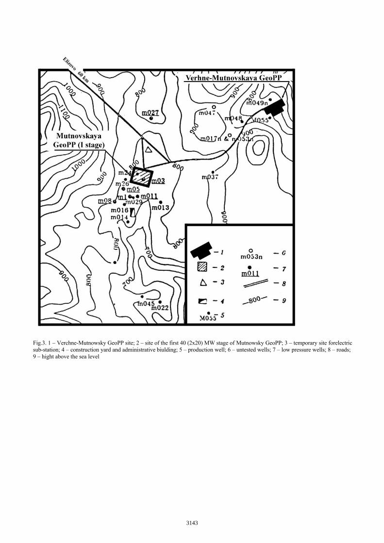
Fig.3. 1 – Verchne-Mutnowsky GeoPP site; 2 – site of the first 40 (2x20) MW stage of Mutnowsky GeoPP; 3 – temporary site forelectricsub-station; 4 – construction yard and administrative biulding; 5 – production well; 6 – untested wells; 7 – low pressure wells; 8 – roads;9 – hight above the sea level
3143
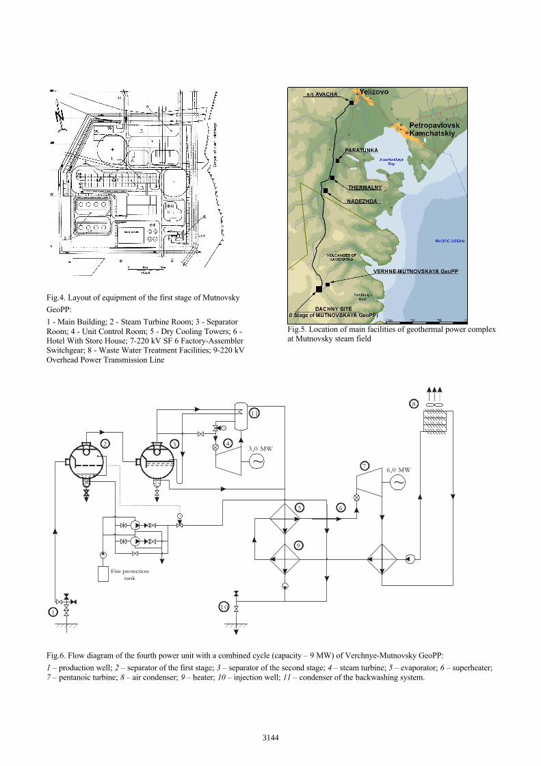
Fig.4. Layout of equipment of the first stage of Mutnovsky
GeoPP:
1 - Main Building; 2 - Steam Turbine Room; 3 - SeparatorRoom; 4 - Unit Control Room; 5 - Dry Cooling Towers; 6 -Hotel With Store House; 7-220 kV SF 6 Factory-AssemblerSwitchgear; 8 - Waste Water Treatment Facilities; 9-220 kVOverhead Power Transmission Line
Fig.5. Location of main facilities of geothermal power complexat Mutnovsky steam field
Fig.6. Flow diagram of the fourth power unit with a combined cycle (capacity – 9 MW) of Verchnye-Mutnovsky GeoPP:
1 – production well; 2 – separator of the first stage; 3 – separator of the second stage; 4 – steam turbine; 5 – evaporator; 6 – superheater;7 – pentanoic turbine; 8 – air condenser; 9 – heater; 10 – injection well; 11 – condenser of the backwashing system.
1
2 3 4
7
8
5
10
11
6
9
Fire protectiontank
~
~
~~
3,0 MW
6,0 MW
3144