mute rail for grand pianos - pianodisc muterail on… · mute rail installation guide for grand...
TRANSCRIPT
PianoDiscMute Rail for Grand Pianos
InstallationGuide
PianoDiscMute Rail Installation Guide for Grand Pianos
Version 5.0 February 2017
4111 North Freeway Blvd.Sacramento, CA 95834
Phone 916.567.9999 Fax 916.567.1941WWW.PianoDisc.Com
2016 by PianoDisc® and Burgett, Inc. All Rights ReservedPianoDisc and Burgett, Inc. reserve the right to change product design and
specifications at any time without prior notice.
Table of Contents
Introduction I
illustration list II
Step 1 Gathering tools 1
Step 2 Disassemble the piano 1
Step 3 Measure the piano 1
Step 4 Mute rail construction 5
Step 5 Mute rail assembly without horn 6
Step 6 Mute rail installation for pianos with horn 8
Step 7 Determining horn hole location 8
Step 8 Installation of Cable Assembly 11
Step 9 Mute rail shimming and foam cushion 12
Step 10 Mute rail fine adjustment 13
I
Introduction
Adding a mute rail…..
A mute rail is a mechanical configuration of parts that will mechanically silence your piano.The hammer motion is stopped just before hitting the stings. A small modification to let-offmay be necessary.
Intention of this manual…..
This installation manual will guide you though the process of fitting the PianoDisc mute railon most all grand piano. Along with any training seminar you might attend, this guideshould be an invaluable resource.
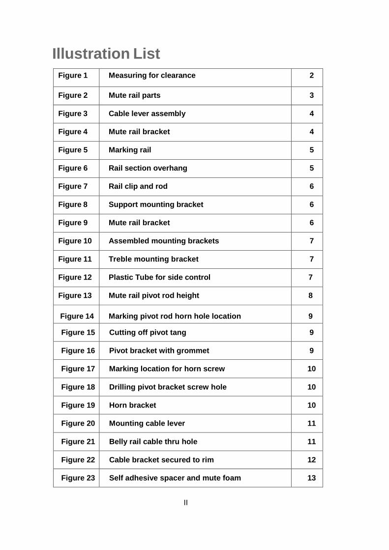
Illustration List
Figure 1 Measuring for clearance 2
Figure 2 Mute rail parts 3
Figure 3 Cable lever assembly 4
Figure 4 Mute rail bracket 4
Figure 5 Marking rail 5
Figure 6 Rail section overhang 5
Figure 7 Rail clip and rod 6
Figure 8 Support mounting bracket 6
Figure 9 Mute rail bracket 6
Figure 10 Assembled mounting brackets 7
Figure 11 Treble mounting bracket 7
Figure 12 Plastic Tube for side control 7
Figure 13 Mute rail pivot rod height 8
Figure 14 Marking pivot rod horn hole location 9
Figure 15 Cutting off pivot tang 9
Figure 16 Pivot bracket with grommet 9
Figure 17 Marking location for horn screw 10
Figure 18 Drilling pivot bracket screw hole 10
Figure 19 Horn bracket 10
Figure 20 Mounting cable lever 11
Figure 21 Belly rail cable thru hole 11
Figure 22 Cable bracket secured to rim 12
Figure 23 Self adhesive spacer and mute foam 13
II
1
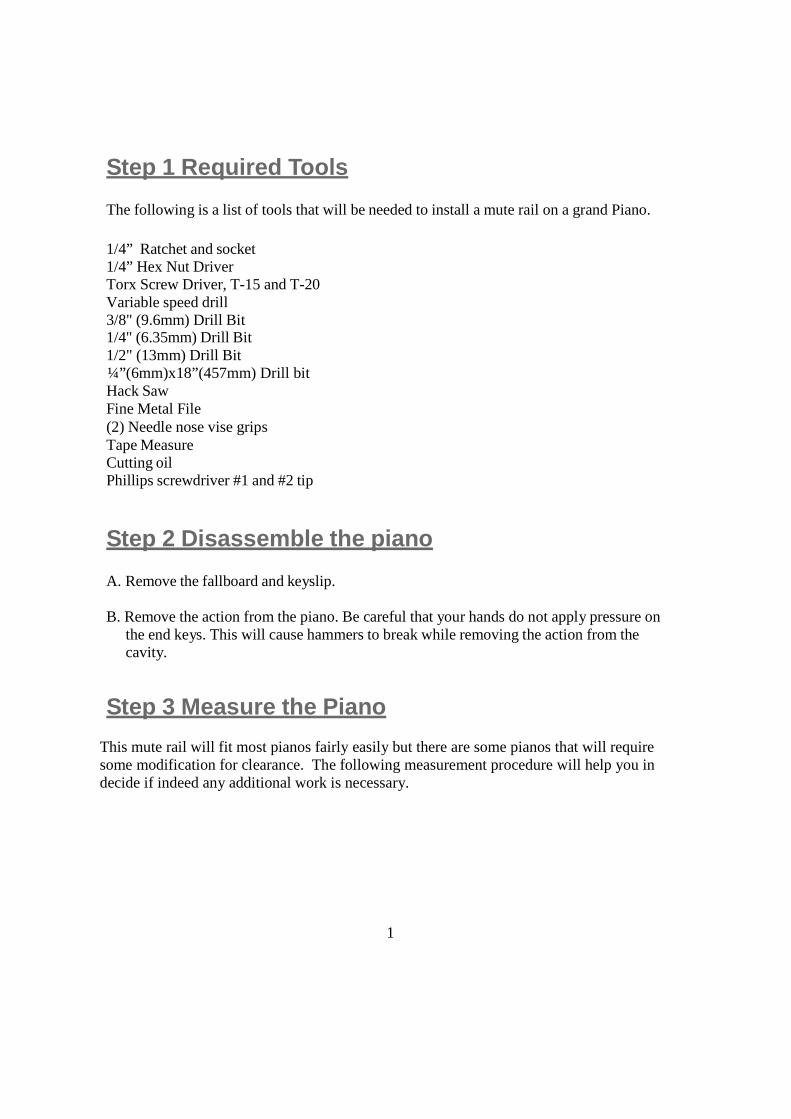
Step 1 Required Tools
The following is a list of tools that will be needed to install a mute rail on a grand Piano.
1/4” Ratchet and socket1/4” Hex Nut DriverTorx Screw Driver, T-15 and T-20Variable speed drill3/8" (9.6mm) Drill Bit1/4" (6.35mm) Drill Bit1/2" (13mm) Drill Bit¼”(6mm)x18”(457mm) Drill bitHack SawFine Metal File(2) Needle nose vise gripsTape MeasureCutting oilPhillips screwdriver #1 and #2 tip
Step 2 Disassemble the piano
A. Remove the fallboard and keyslip.
B. Remove the action from the piano. Be careful that your hands do not apply pressure onthe end keys. This will cause hammers to break while removing the action from thecavity.
Step 3 Measure the Piano
This mute rail will fit most pianos fairly easily but there are some pianos that will requiresome modification for clearance. The following measurement procedure will help you indecide if indeed any additional work is necessary.
2
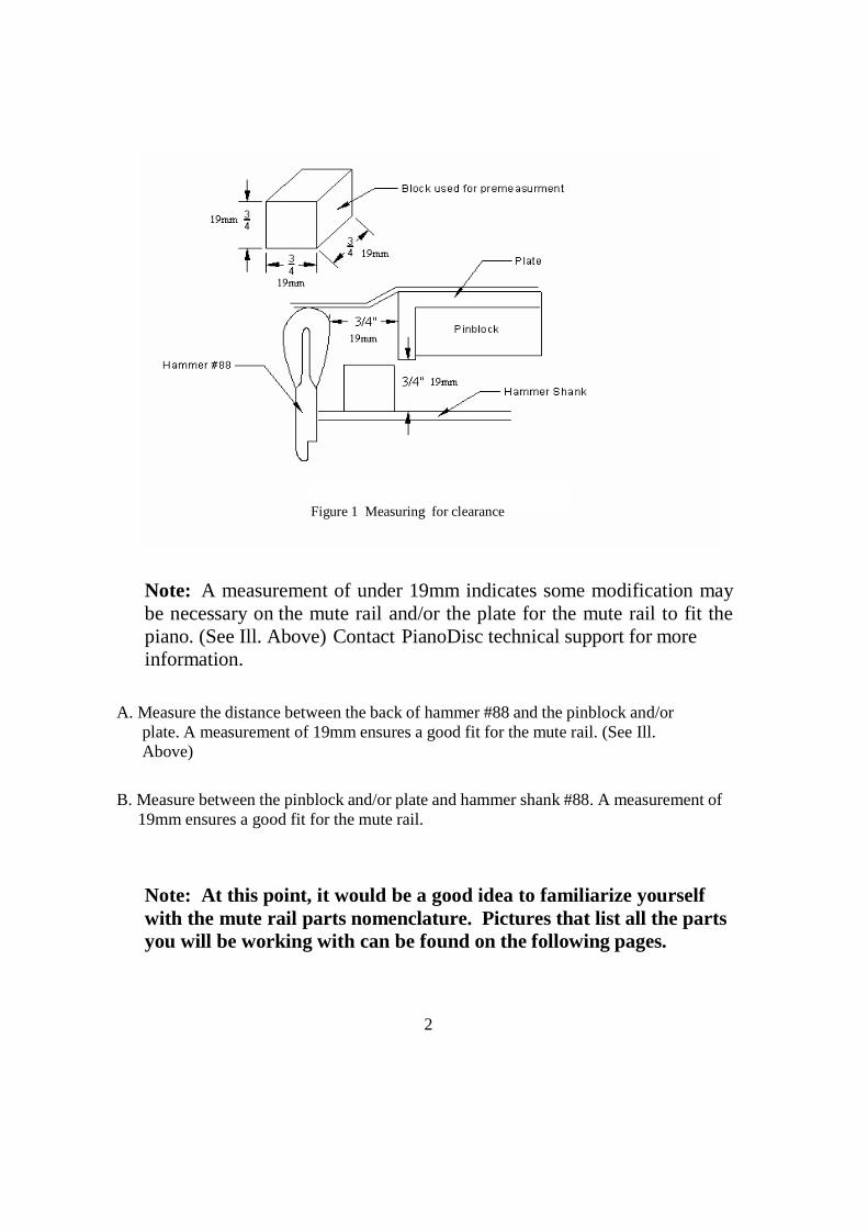
Figure 1 Measuring for clearance
Note: A measurement of under 19mm indicates some modification maybe necessary on the mute rail and/or the plate for the mute rail to fit thepiano. (See Ill. Above) Contact PianoDisc technical support for moreinformation.
A. Measure the distance between the back of hammer #88 and the pinblock and/orplate. A measurement of 19mm ensures a good fit for the mute rail. (See Ill.Above)
B. Measure between the pinblock and/or plate and hammer shank #88. A measurement of19mm ensures a good fit for the mute rail.
Note: At this point, it would be a good idea to familiarize yourselfwith the mute rail parts nomenclature. Pictures that list all the partsyou will be working with can be found on the following pages.
3
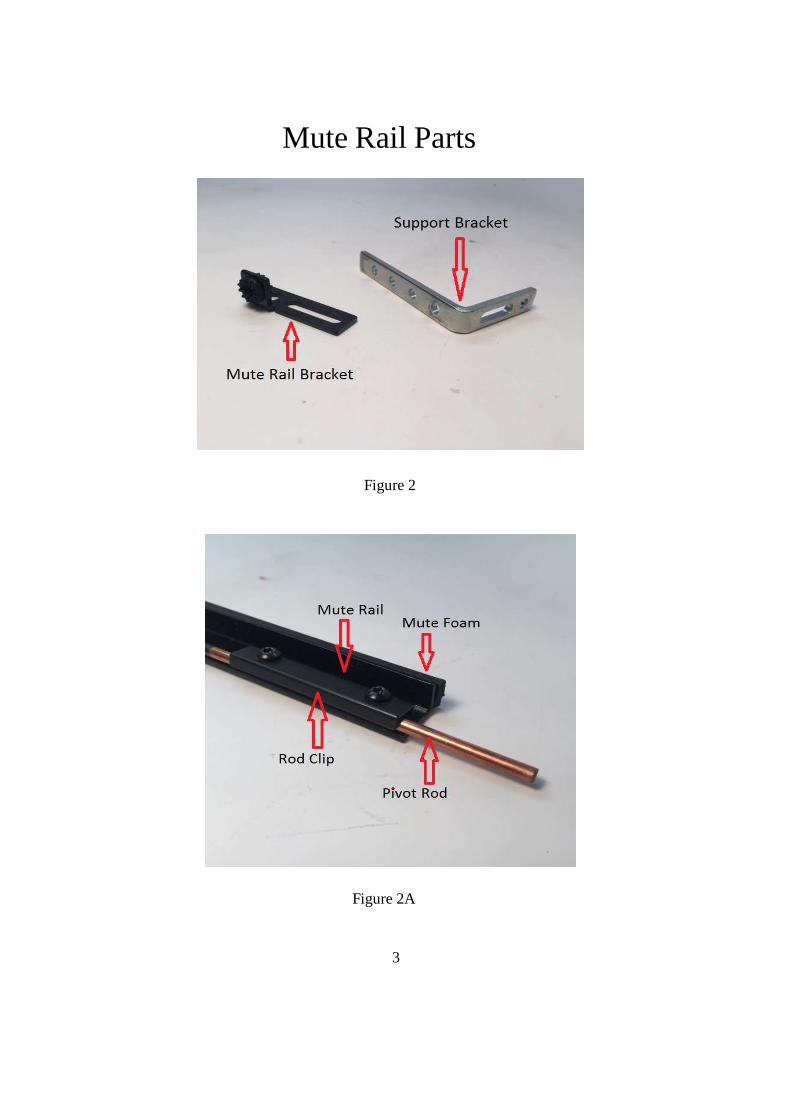
Mute Rail Parts
Figure 2
Figure 2A
4
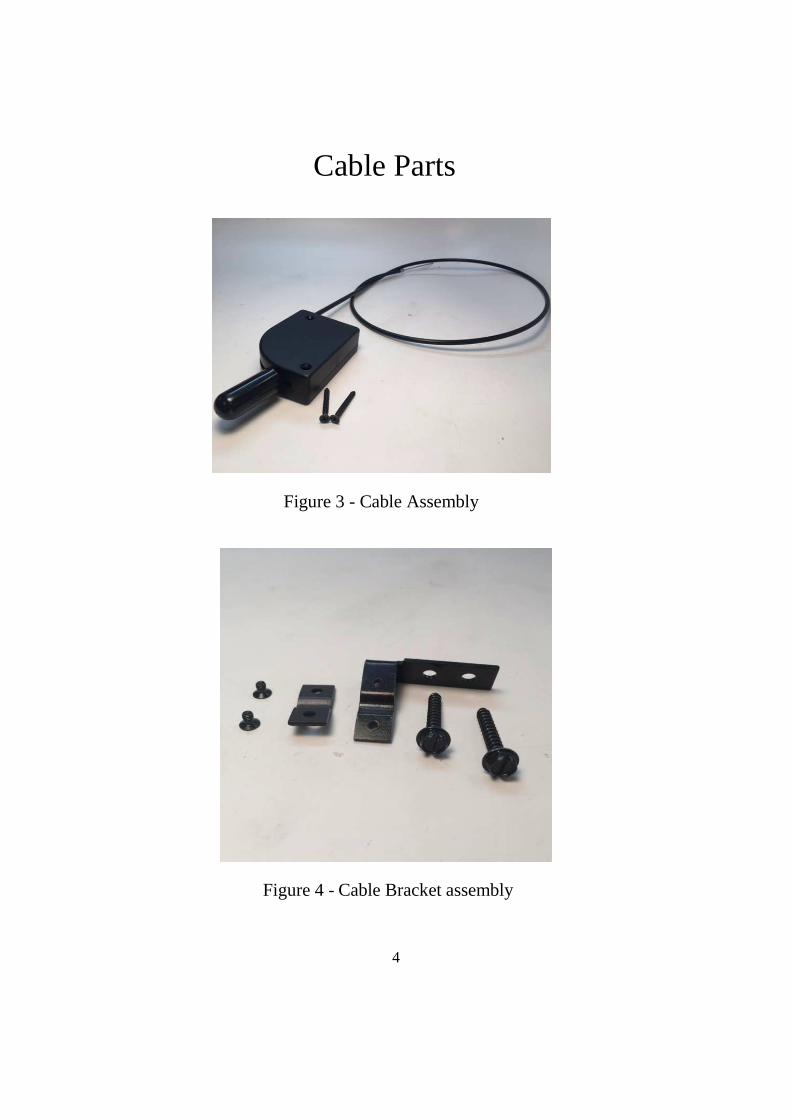
Cable Parts
Figure 3 - Cable Assembly
Figure 4 - Cable Bracket assembly
5
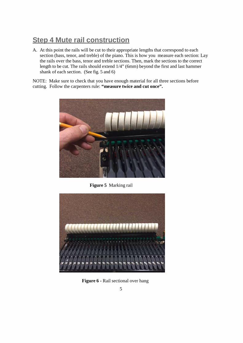
Step 4 Mute rail construction
A. At this point the rails will be cut to their appropriate lengths that correspond to eachsection (bass, tenor, and treble) of the piano. This is how you measure each section: Laythe rails over the bass, tenor and treble sections. Then, mark the sections to the correctlength to be cut. The rails should extend 1/4” (6mm) beyond the first and last hammershank of each section. (See fig. 5 and 6)
NOTE: Make sure to check that you have enough material for all three sections beforecutting. Follow the carpenters rule: “measure twice and cut once”.
Figure 5 Marking rail
Figure 6 - Rail sectional over hang
6
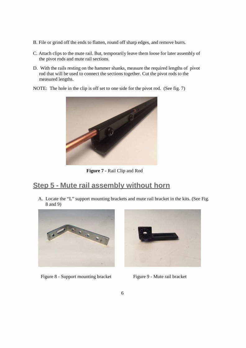
B. File or grind off the ends to flatten, round off sharp edges, and remove burrs.
C. Attach clips to the mute rail. But, temporarily leave them loose for later assembly ofthe pivot rods and mute rail sections.
D. With the rails resting on the hammer shanks, measure the required lengths of pivotrod that will be used to connect the sections together. Cut the pivot rods to themeasured lengths.
NOTE: The hole in the clip is off set to one side for the pivot rod. (See fig. 7)
Figure 7 - Rail Clip and Rod
Step 5 - Mute rail assembly without horn
A. Locate the “L” support mounting brackets and mute rail bracket in the kits. (See Fig.8 and 9)
Figure 8 - Support mounting bracket Figure 9 - Mute rail bracket
7
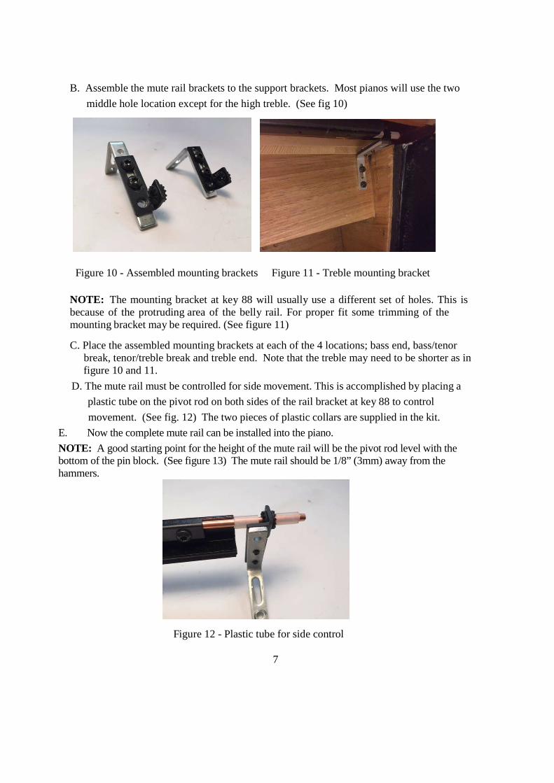
B. Assemble the mute rail brackets to the support brackets. Most pianos will use the two
middle hole location except for the high treble. (See fig 10)
Figure 10 - Assembled mounting brackets Figure 11 - Treble mounting bracket
NOTE: The mounting bracket at key 88 will usually use a different set of holes. This isbecause of the protruding area of the belly rail. For proper fit some trimming of themounting bracket may be required. (See figure 11)
C. Place the assembled mounting brackets at each of the 4 locations; bass end, bass/tenorbreak, tenor/treble break and treble end. Note that the treble may need to be shorter as infigure 10 and 11.
D. The mute rail must be controlled for side movement. This is accomplished by placing a
plastic tube on the pivot rod on both sides of the rail bracket at key 88 to control
movement. (See fig. 12) The two pieces of plastic collars are supplied in the kit.
E. Now the complete mute rail can be installed into the piano.
NOTE: A good starting point for the height of the mute rail will be the pivot rod level with thebottom of the pin block. (See figure 13) The mute rail should be 1/8” (3mm) away from thehammers.
Figure 12 - Plastic tube for side control
8
For pianos without a horn, skip steps 6, 7. Continue to step 8.
Step 6 Mute rail installation for pianos with horn
The horn of the piano can be described as a downward projecting part of the plate that ex-tends to the belly rail at the cross point of the bass and tenor sections. If the piano has a horn,most likely the horn will be in the way of the mute rail. If this is the case it will be necessaryto drill an access hole through the plate horn.
Note: For determining horn hole location it will be necessary to assemble the bass muterail first and mount into the piano to determine the hole location thru the horn.
Step 7 Determining horn hole location
NOTE: Years ago we supplied a “Dummy Mute Rail” for locating the hole location thruthe plate horn at the bass/tenor location, but this was not necessary as the bass mute railsection can be used for the same purpose.
A. Mount the bass mute rail (with cushion foam attached to rail) into the bass section.
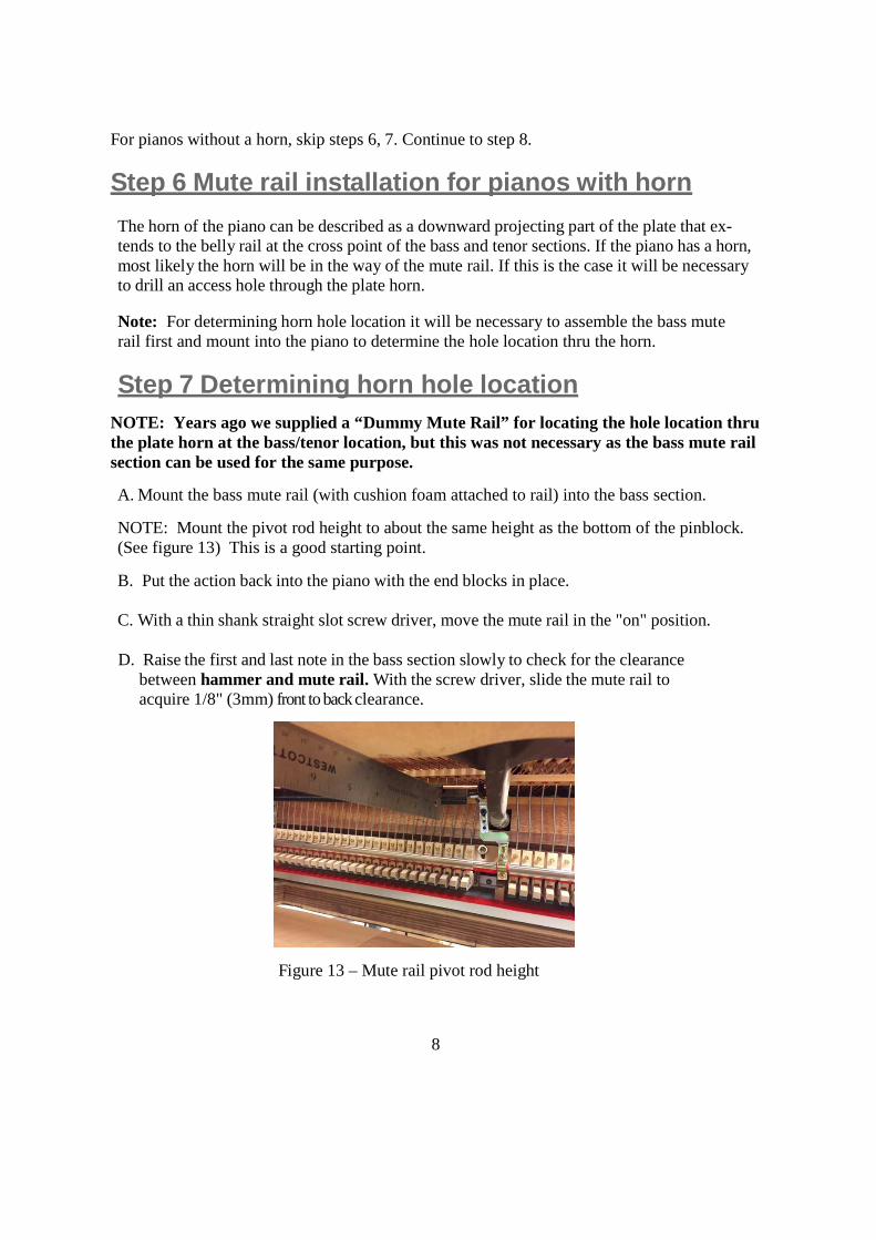
NOTE: Mount the pivot rod height to about the same height as the bottom of the pinblock.(See figure 13) This is a good starting point.
B. Put the action back into the piano with the end blocks in place.
C. With a thin shank straight slot screw driver, move the mute rail in the "on" position.
D. Raise the first and last note in the bass section slowly to check for the clearancebetween hammer and mute rail. With the screw driver, slide the mute rail toacquire 1/8" (3mm) front to backclearance.
Figure 13 – Mute rail pivot rod height
9
E. While playing the last bass note (next to the horn) with a medium blow, bend thebracket up to where you hear the hammer is hitting the string. Then bend the bracketdown slightly to keep the hammer from hitting the string. The rail should be in theapproximate area of letoff position. This is the ideal place to drill the hole thru thehorn.
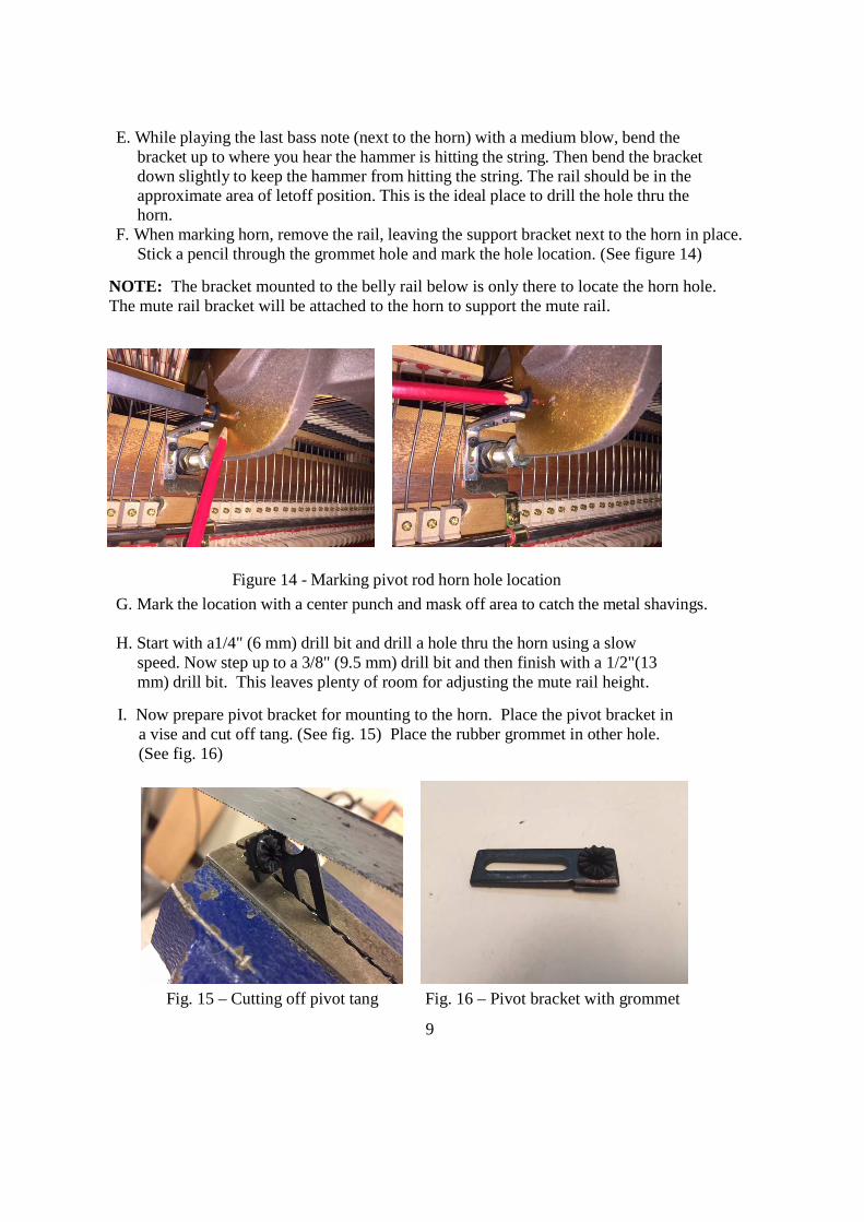
F. When marking horn, remove the rail, leaving the support bracket next to the horn in place.Stick a pencil through the grommet hole and mark the hole location. (See figure 14)
NOTE: The bracket mounted to the belly rail below is only there to locate the horn hole.The mute rail bracket will be attached to the horn to support the mute rail.
Figure 14 - Marking pivot rod horn hole location
G. Mark the location with a center punch and mask off area to catch the metal shavings.
H. Start with a1/4" (6 mm) drill bit and drill a hole thru the horn using a slowspeed. Now step up to a 3/8" (9.5 mm) drill bit and then finish with a 1/2"(13mm) drill bit. This leaves plenty of room for adjusting the mute rail height.
I. Now prepare pivot bracket for mounting to the horn. Place the pivot bracket ina vise and cut off tang. (See fig. 15) Place the rubber grommet in other hole.(See fig. 16)
Fig. 15 – Cutting off pivot tang Fig. 16 – Pivot bracket with grommet
10
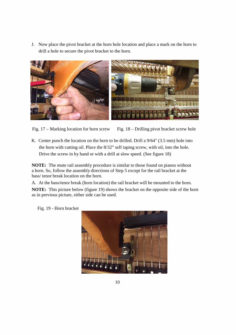
J. Now place the pivot bracket at the horn hole location and place a mark on the horn to
drill a hole to secure the pivot bracket to the horn.
Fig. 17 – Marking location for horn screw Fig. 18 – Drilling pivot bracket screw hole
K. Center punch the location on the horn to be drilled. Drill a 9/64" (3.5 mm) hole into
the horn with cutting oil. Place the 8/32” self taping screw, with oil, into the hole.
Drive the screw in by hand or with a drill at slow speed. (See figure 18)
NOTE: The mute rail assembly procedure is similar to those found on pianos withouta horn. So, follow the assembly directions of Step 5 except for the rail bracket at thebass/ tenor break location on the horn.
A. At the bass/tenor break (horn location) the rail bracket will be mounted to the horn.
NOTE: This picture below (figure 19) shows the bracket on the opposite side of the hornas in previous picture, either side can be used.
Fig. 19 - Horn bracket
11
Step 8 Installation of cable assembly
Note: The cable lever can be mounted on either side of the piano under the keybed.Normally the left hand side is used.
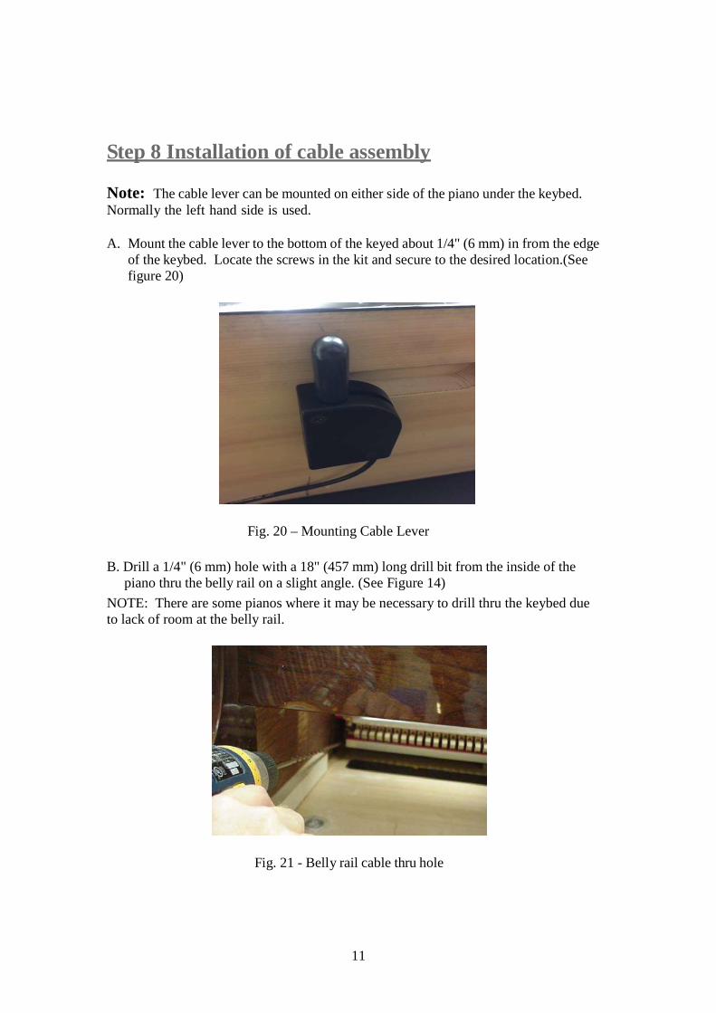
A. Mount the cable lever to the bottom of the keyed about 1/4" (6 mm) in from the edgeof the keybed. Locate the screws in the kit and secure to the desired location.(Seefigure 20)
Fig. 20 – Mounting Cable Lever
B. Drill a 1/4" (6 mm) hole with a 18" (457 mm) long drill bit from the inside of thepiano thru the belly rail on a slight angle. (See Figure 14)
NOTE: There are some pianos where it may be necessary to drill thru the keybed dueto lack of room at the belly rail.
Fig. 21 - Belly rail cable thru hole
12
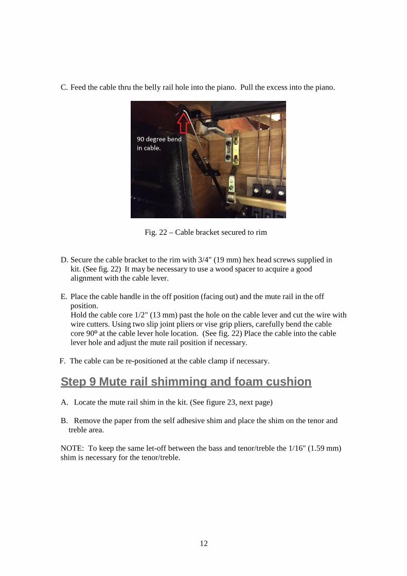
C. Feed the cable thru the belly rail hole into the piano. Pull the excess into the piano.
Fig. 22 – Cable bracket secured to rim
D. Secure the cable bracket to the rim with 3/4" (19 mm) hex head screws supplied inkit. (See fig. 22) It may be necessary to use a wood spacer to acquire a goodalignment with the cable lever.
E. Place the cable handle in the off position (facing out) and the mute rail in the offposition.Hold the cable core 1/2" (13 mm) past the hole on the cable lever and cut the wire withwire cutters. Using two slip joint pliers or vise grip pliers, carefully bend the cablecore 90º at the cable lever hole location. (See fig. 22) Place the cable into the cablelever hole and adjust the mute rail position if necessary.
F. The cable can be re-positioned at the cable clamp if necessary.
Step 9 Mute rail shimming and foam cushion
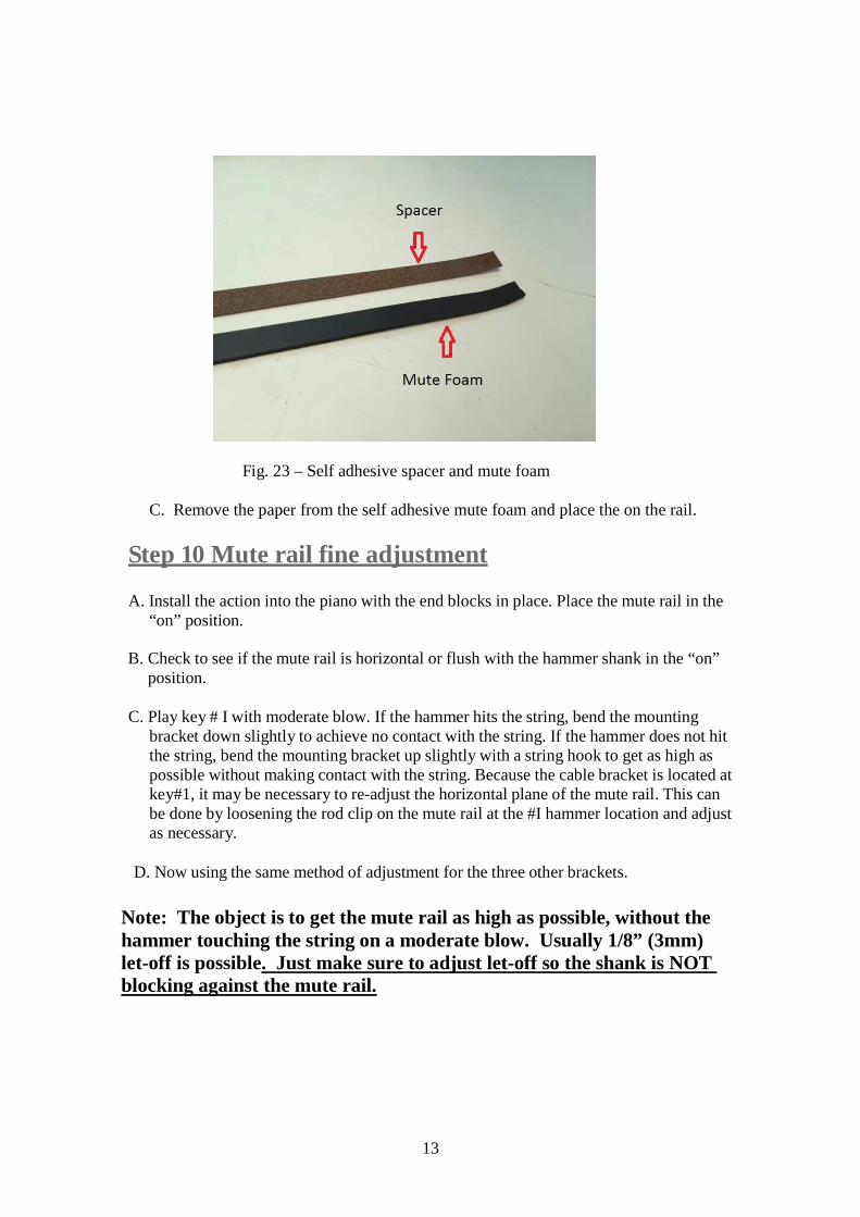
A. Locate the mute rail shim in the kit. (See figure 23, next page)
B. Remove the paper from the self adhesive shim and place the shim on the tenor andtreble area.
NOTE: To keep the same let-off between the bass and tenor/treble the 1/16" (1.59 mm)shim is necessary for the tenor/treble.
13
Fig. 23 – Self adhesive spacer and mute foam
C. Remove the paper from the self adhesive mute foam and place the on the rail.
Step 10 Mute rail fine adjustment
A. Install the action into the piano with the end blocks in place. Place the mute rail in the“on” position.
B. Check to see if the mute rail is horizontal or flush with the hammer shank in the “on”position.
C. Play key # I with moderate blow. If the hammer hits the string, bend the mountingbracket down slightly to achieve no contact with the string. If the hammer does not hitthe string, bend the mounting bracket up slightly with a string hook to get as high aspossible without making contact with the string. Because the cable bracket is located atkey#1, it may be necessary to re-adjust the horizontal plane of the mute rail. This canbe done by loosening the rod clip on the mute rail at the #I hammer location and adjustas necessary.
D. Now using the same method of adjustment for the three other brackets.
Note: The object is to get the mute rail as high as possible, without thehammer touching the string on a moderate blow. Usually 1/8” (3mm)let-off is possible. Just make sure to adjust let-off so the shank is NOTblocking against the mute rail.