multivariable model predictive control - distillation ... · multivariable model predictive control...
TRANSCRIPT

Applications for Process Automation
Multivariable Model Predictive Control - Distillation Column as an Application Example
Application Note

Warranty, Liability and Support
MPC 37361208
Version V1.0 July 9, 2009 2/36
Cop
yrig
ht ©
Sie
men
s A
G 2
009
All
right
s re
serv
ed
Note The application examples are not binding and do not claim to be com-plete regarding the circuits shown, equipment and possibilities. The soft-ware samples do not represent a customer-specific solution. They only serve as a support for typical applications. You are responsible for ensur-ing that the described products are used correctly. These application ex-amples do not release you from your own responsibility regarding profes-sional usage, installation, operation and maintenance of the plant. When using these application examples, you acknowledge that Siemens cannot be made liable for any damage/claims beyond the scope described in the liability clause. We reserve the right to make changes to these application examples at any time without prior notice. If there are any deviations be-tween the recommendations provided in these application examples and other Siemens publications – e.g. catalogs – then the contents of the o-ther documents have priority.
Warranty, Liability and Support We accept no liability for information contained in this document.
Any claims against us – based on whatever legal reason – resulting from the use of the examples, information, programs, engineering and perform-ance data etc., described in this application example shall be excluded. Such an exclusion shall not apply in the case of mandatory liability, e.g. un-der the German Product Liability Act (“Produkthaftungsgesetz”), in case of intent, gross negligence, or injury of life, body or health, guarantee for the quality of a product, fraudulent concealment of a deficiency or breach of a condition which goes to the root of the contract (“wesentliche Ver-tragspflichten”). The damages for a breach of a substantial contractual obli-gation are, however, limited to the foreseeable damage, typical for the type of contract, except in the event of intent or gross negligence or injury to life, body or health. The above provisions do not imply a change in the burden of proof to the detriment of the orderer.
Copyright© 2009 Siemens Industry Sector IA. These application ex-amples or extracts from them must not be transferred or copied with-out the approval of Siemens. For questions about this document please use the following e-mail address:
mailto:[email protected]

Preface
MPC 37361208
Version V1.0 July 9, 2009 3/36
Cop
yrig
ht ©
Sie
men
s A
G 2
009
All
right
s re
serv
ed
Preface
Objective of the Application The objective is fast and tight control of processes with several interacting in- and outputs. In the accompanying example the MPC controls two sub-ordinated PID controllers in a cascade structure. This demonstration with two manipulated and two control variables is only an application example. The procedure to configure an MPC with more or less than two manipu-lated variables is the same.
This application note is intended for non experienced users in MPC tech-nology; special cases and complex applications are not considered here.
The application example considered here shows the enhancement of a ba-sically automated distillation column with a MPC based temperature con-trol.
Main Contents of this Application Note The following issues are discussed in this application:
• How to create an instance of the process tag type
• How to collect the necessary measurement data for the MPC
• Configuration using the MPC configurator
• How to handle more than one measurable disturbance variable
• Benchmark simulations with and without MPC, to show the potential benefits
Validity … valid for PCS 7 V7.1, in principal transferable to V7.0.
Reference to Automation and Drives Service & Support This article is from the internet application portal of the Industry Automation and Drives Technologies Service & Support. Clicking the link below directly displays the download page of this document.
http://support.automation.siemens.com/WW/view/en/37361208

Table of Contents
MPC 37361208
Version V1.0 July 9, 2009 4/36
Cop
yrig
ht ©
Sie
men
s A
G 2
009
All
right
s re
serv
ed
Table of Contents
Table of Contents ......................................................................................................... 4
1 Basic Principles of Model Predictive Control .............................................. 5
2 Implementation of the MPC ........................................................................... 6 2.1 Installation......................................................................................................... 6 2.2 Configuration: Creating an Instance of the Process Tag Type (CFC Template)6
3 Generation of Measurement Data for the Identification............................ 13
4 Configuration and Implementation of the MPC.......................................... 17 4.1 MPC Configurator ........................................................................................... 17 4.2 Integration of Control Parameters................................................................... 23 4.3 Parameterization during Operation................................................................. 24
5 Model Predictive Control with more than one Measureable Disturbance25
6 Simulation Example...................................................................................... 27 6.1 Distillation Column .......................................................................................... 27 6.2 Conventional Single-Input Single-Output Control ........................................... 28 6.3 Control via MPC.............................................................................................. 31
7 Conclusion .................................................................................................... 34
8 History ........................................................................................................... 36
9 Literature ....................................................................................................... 36

Basic Principles of Model Predictive Control
MPC 37361208
Version V1.0 July 9, 2009 5/36
Cop
yrig
ht ©
Sie
men
s A
G 2
009
All
right
s re
serv
ed
1 Basic Principles of Model Predictive Control
A general overview of model predictive control is provided by the White Pa-per “How to improve the Performance of your Plant using the appropriate tools of SIMATIC PCS 7 APC-Portfolio?”
https://pcs.khe.siemens.com/efiles/pcs7/support/marktstudien/WP_PCS7_APC_EN.pdf
PCS 7 embedded MPC: Method of Operation und Area of Application The ModPreCon block is used for multivariable control of dynamic proc-esses (see the online help “Description of ModPreCon”). It can handle up to four dependent manipulated and controlled variables as well as one meas-urable disturbance variable.
In special situations, the ModPreCon block can also be used for SISO (sin-gle-input single-output) controls with particularly difficult dynamics. It per-forms better than a PID controller, for example, in systems with non-minimum phase or a strongly oscillating response.
The ModPreCon algorithm only works for stable processes with a step re-sponse that settles to a fixed value in a finite time. If the process is unstable or includes an integrator (tank level control for example), the corresponding partial transfer function must be stabilized with a secondary controller.
Note The run time of the multivariable controller is basically longer than that for PID controllers, because large matrices have to be multiplied in the algo-rithm. The run time is also determined by number of process and manipu-lated variables in the control algorithm. This is why the multivariable con-troller is unsuited for rapid control and is usually applied for slow, com-plex control tasks. The computation time required on the CPU is com-pensated by the fact that very slow sample times of > 20s are used for the typical ModPreCon applications (see Advanced control templates). The ModPreCon is then typically running in OB30 and can be interrupted by faster OBs.

Implementation of the MPC
MPC 37361208
Version V1.0 July 9, 2009 6/36
Cop
yrig
ht ©
Sie
men
s A
G 2
009
All
right
s re
serv
ed
2 Implementation of the MPC
The principal approach to configure a model predictive controller is very similar to the computer-based commissioning of a PID controller. Due to the matrix form of the control parameters within the MPC, the interaction between control block and configurator is organised differently. The con-figuration is done in several steps (see the online help of ModPreCon block) as it is explained in the next chapters:
• Excite the process with the controller in manual mode by applying a se-ries of manipulated variable step changes.
• Record the measured data with the CFC trend display and export it to an archive file.
• Using the MPC configurator, create an SCL source code for the user data block (DB). It contains the models and matrices required for a ModPreCon instance.
• Compile the SCL source code in the engineering system and download it to the AS.
2.1 Installation
The installation of the PCS 7 Advanced Process Library is performed automatically by the PCS 7 master setup V7.1.
Note There is a MPC process tag type named “MPC_CTRL” already available in the PCS 7 APC Library V7.0 SP1. Although the Advanced Process Library of PCS 7 V7.1 is used in this Application Note, the principal pro-cedure is also applicable to the APC library of PCS 7 V7.0 SP1.
2.2 Configuration: Creating an Instance of the Process Tag Type (CFC Template)
The following steps are carried out for the MPC in the same way as for any other process tag types (CFC templates).
1. Please open PCS 7 Advanced Process Library V71 with the menu “File > Open > Libraries” in SIMATIC Manager.

Implementation of the MPC
MPC 37361208
Version V1.0 July 9, 2009 7/36
Cop
yrig
ht ©
Sie
men
s A
G 2
009
All
right
s re
serv
ed
Figure 2-1: Open the PCS 7 AP Library V71
2. Copy the process tag type “ModPreCon“ from the subfolder “Templates“ into the master data library of your PCS 7 multiproject.
3. Modify it if this is necessary according to your general application re-quirements.

Implementation of the MPC
MPC 37361208
Version V1.0 July 9, 2009 8/36
Cop
yrig
ht ©
Sie
men
s A
G 2
009
All
right
s re
serv
ed
Figure 2-2: Selection of the process tag type
4. Copy the process tag type from the master data library to the target folder (Process cell > unit etc.) in the plant view. You obtain an instance of the process tag type i.e. a CFC chart, which indicates its origin by its symbolic representation.
5. Rename the new CFC chart and check if the cyclic interrupt OB is cor-rect (in the CFC chart “Edit > Open run sequence”).
6. Open the CFC chart and implement the following connections:
• Control variables: Connect the analog input drivers “Pcs7AnIn” for both control variables “CV1“ and “CV2“ (see figure Figure 2-3, num-ber 1) with the symbolic names of the corresponding peripheral sig-nals from the hardware configuration. The units of the signals can be adjusted at the input “PV_InUni“.
• Disturbance variable: The measureable disturbance variable (if available) has to be linked to the input “DV1” of the MPC block (ModPreCon) (see figure Figure 2-3, number 2). If more than one measureable disturbance variable is affecting the process the addi-tional signals can be considered too (see chapter 5).
• Manipulated variables: Both manipulated variables “MV1“ and “MV2“ have to be connected to the periphery via the analog output drivers “Pcs7AnOu” (see figure Figure 2-3, number 3 for the original process tag type). For using the manipulated variables as external set points for the slave PID controllers (as it is done in this example) the connections must be different. The outputs “MV1” and MV2” of the MPC block must be connected directly to the inputs “SP_Ext” (external set point) of the corresponding PID controllers (see figure

Implementation of the MPC
MPC 37361208
Version V1.0 July 9, 2009 9/36
Cop
yrig
ht ©
Sie
men
s A
G 2
009
All
right
s re
serv
ed
Figure 2-4, number 3 for the cascade control). The inputs “MV1Trk“ and “MV2Trk“ of the MPC block (see figure Figure 2-3, number 4 and figure Figure 2-4, number 4) must be connected to the corre-sponding process values of the PID controllers to provide the infor-mation of the process values achieved by the PID controllers to the MPC. Therefore, the existing connections from the outputs “MV1” and “MV2” to the inputs “MV1Trk” and “MV2Trk” of the MPC block must be deleted. The units of the signals can be adjusted at the in-put “PV_InUni” of the analog output drivers “Pcs7AnOu” for the original process tag type (no cascade control) and via the units of the process variables of the slave control loops for cascade control.
• Monitoring: A further logical OR-block must be inserted for each cascade to monitor the connection inside the cascade. The first in-put of these OR-blocks has to be connected to the output of the block “CV_Bad” (see figure Figure 2-4, number 5) to monitor the process values of the MPC. The second input must be connected to the output “CascaCut” of the related slave PID controller. The out-puts of the OR-blocks must be connected to the inputs “MV1TrkOn” and “MV2TrkOn” of the MPC block.

Implementation of the MPC
MPC 37361208 Figure 2-3: Important connections of the original measurement tag type with direct access to the actuator
Version V1.0 July 9, 2009 10/36
Cop
yrig
ht ©
Sie
men
s A
G 2
009
All
right
s re
serv
ed
1 1
2
3
4
5

Implementation of the MPC
MPC 37361208
Figure 2-4: Important connections of the measurement tag type with cascade control
Version V1.0 July 9, 2009 11/36
Cop
yrig
ht ©
Sie
men
s A
G 2
009
All
right
s re
serv
ed
1 1
2
3
4
5
…/P
ID/S
P_Ex
t
…/P
ID/S
P_Ex
t

Implementation of the MPC
MPC 37361208
Version V1.0 July 9, 2009 12/36
Cop
yrig
ht ©
Sie
men
s A
G 2
009
All
right
s re
serv
ed
Hinweis As long as the controller is not adapted to the process (no user data block for the underlying application is generated and loaded) it can only be run in manual mode.
7. Compile and download your changes to the AS. Compile the OS again to include the MPC faceplate in your runtime application.
Now you have successfully integrated the MPC to your process. In the next step the MPC must be configured to match your plant behaviour. Therefore, measurement data must be generated to identify the sub process of inter-est.

Generation of Measurement Data for the Identification
MPC 37361208
3 Generation of Measurement Data for the Identification
Excitation of Process and Recording of Training Data The process is excited with stepwise changes of the manipulated and if possible of the disturbance variables in manual mode of the MPC. These measurement data is collected with the CFC trend display and exported to an archive file.
1. Select “Trend Display“ in the menu “View“ in the CFC to open the trend display.
Figure 3-1: CFC trend display
Version V1.0 July 9, 2009 13/36
Cop
yrig
ht ©
Sie
men
s A
G 2
009
All
right
s re
serv
ed

Generation of Measurement Data for the Identification
MPC 37361208
2. Generate a new trend display and specify several parameters with the “Change” button:
• The number of collected measured values;
• The acquisition cycle: It must be an integer multiple of the related inter-rupt OB and should be large enough to collect sufficient step re-sponses. The rule of thumb says that the shortest transient effect (step response) should be collected within approximately 200 measured val-ues. The maximal time range captured with these settings results from the multiplication of the number of measured values and the acquisition cycle.
Figure 3-2: Settings for the recording
Version V1.0 July 9, 2009 14/36
Cop
yrig
ht ©
Sie
men
s A
G 2
009
All
right
s re
serv
ed
3. In the next step the variables (manipulated, controlled and disturbance variables) to be captured must be selected. Move the corresponding signals via drag&drop from the CFC of the MPC to the trend display.
4. Select the value part of the data structure and apply it to a free channel.

Generation of Measurement Data for the Identification
MPC 37361208
Version V1.0 July 9, 2009 15/36
Cop
yrig
ht ©
Sie
men
s A
G 2
009
All
right
s re
serv
ed
5. Move your process to its operating point and wait for a steady state. Now you can start with the recording of measurement data. Be sure to decide which step changes to the manipulated and disturbance vari-ables you want to apply before starting the recording. Some notes on this topic are given in the following: The measurement data should be symmetrical to the operating point for a successful identification. There-fore, a single step response is not adequate. Another point is that the dynamic of the process should be excited completely. As an example of a possible excitation step responses of the first manipulated variable could be executed first while in-between two changes steady state must be reached. Afterwards the same scenario with the other manipulated and disturbance variables can be carried out. Figure Figure 3-3 shows an example.
Hinweis Additional remarks to the choice of excitation are given in the online help of the MPC configurator (“The individual design steps in detail > Re-cording the measurement series”).
6. Before starting with the recording be sure to activate the external set points of the slave PID controllers (“SP_ExtOp=1” for “SP_LiOp=0” (de-fault value) or “SP_ExtLi=1” for “SP_LiOp=1”).
7. Switch on the test mode of the CFC and start the recording with the trend display. Apply your decided step changes to the manipulated and the disturbance variables successively.

Generation of Measurement Data for the Identification
MPC 37361208 Figure 3-3: Recording of measurement data (clipped in time)
Version V1.0 July 9, 2009 16/36
Cop
yrig
ht ©
Sie
men
s A
G 2
009
All
right
s re
serv
ed
8. If all step changes are finished and the process is in steady state again, the recording can be stopped.
9. Export the measurement data to a csv-file via the “Export” button. Please keep the predefined settings.
10. If a validation of the identified model during the MPC configuration is desired, you have to generate an additional measurement data set in the same way as for the identification, but with a different excitation sig-nal.

Configuration and Implementation of the MPC
MPC 37361208
4 Configuration and Implementation of the MPC
Version V1.0 July 9, 2009 17/36
Cop
yrig
ht ©
Sie
men
s A
G 2
009
All
right
s re
serv
ed
4.1 MPC Configurator
The configuration is done with the MPC configurator. Select the MPC block in the CFC and start the configurator via the menu “Edit > Configure MPC”. Figure 4-1: Start window of the MPC configurator
1. Select your recorded measurement data via “load data“. Thereupon all captured variables are displayed in the window.

Configuration and Implementation of the MPC
MPC 37361208
Version V1.0 July 9, 2009 18/36
Cop
yrig
ht ©
Sie
men
s A
G 2
009
All
right
s re
serv
ed
Figure 4-2: Settings for the measurement data
2. Assign its role to each variable and specify if it is a manipulated, con-trolled or disturbance variable or if it is not relevant.
3. In the lower part of the window the time range of the measurement data can be adjusted. If your process has dead times, mark the appropriate tick mark. Moreover it is possible to smooth the measurements with a noise filter and to downsample the data to reduce the amount of data.
It is possible to load several different data sets, or equal data sets with dif-ferent time ranges. All loaded data is considered for the identification.
4. Right click on the name of the corresponding file in the data selection to remove a data set from the identification.

Configuration and Implementation of the MPC
MPC 37361208
5. The identification can be started via the “Identify“ button. The results of the identification are shown in a new window (see figure Figure 4-3).
Version V1.0 July 9, 2009 19/36
Cop
yrig
ht ©
Sie
men
s A
G 2
009
All
right
s re
serv
ed
Figure 4-3: Results of the identification
6. Evaluate these results carefully and decide if this model has the ade-quate accuracy for the MPC design.
• The Bode diagrams can be analysed by clicking on the step responses.
• A click on the control variables shows a comparison of measured and calculated data of the model as can be seen in figure Figure 4-4.
• Altogether the model accuracy should be as high as possible but more than 50%, the dynamic should be covered adequately and the step re-sponses should be stable.

Configuration and Implementation of the MPC
MPC 37361208
Version V1.0 July 9, 2009 20/36
Cop
yrig
ht ©
Sie
men
s A
G 2
009
All
right
s re
serv
ed
Figure 4-4: Accuracy of the model (Model qualities of 99% can only be achieved with simu-lated data.)
If the model identification is finished, the design of the MPC can be started. The MPC algorithm is based on a quality criterion of control error and movement of manipulated variables:
( ) ( ) uQuywRywJTT
Δ⋅⋅Δ+−⋅⋅−= .
The diagonal weighting matrices R and Q affect the intensity of the control-ler action.

Configuration and Implementation of the MPC
MPC 37361208
Version V1.0 July 9, 2009 21/36
Cop
yrig
ht ©
Sie
men
s A
G 2
009
All
right
s re
serv
ed
Controller parameterization In figure Figure 4-3 some settings can be specified to parameterize the controller:
• Weighting of the controlled variables: These are the diagonal ele-ments of matrix R corresponding to the related controlled variable over the whole prediction horizon. The weighting indicates the im-portance of each controlled variable. E.g. higher weighting of con-trolled variable 1 than controlled variable 2 leads to a faster and more accurate reduction of the control error for the first controlled variable than for the second one.
• Penalization of the manipulated variable: These are the diagonal elements of matrix Q corresponding to the moves of the related ma-nipulated variable over the whole control horizon. If you increase the weighting, the changes in the manipulated variable are penalized more strongly and the controller moves its manipulated variable more cautiously resulting in a slower but more robust control action.
• Controller sample time: The MPC configurator recommends a suit-able value for the sample time based on the identified model to cover the slowest step response within at most 100 samples. In general these recommendations should not be changed. Move the CFC runtime group of the MPC measurement tag type in the inter-rupt OB with the recommended sample time. If the controller sample time is displayed in red, you will need to install the function block in OB30 although the controller sample time is higher than 20 s. The function block is then called every 20 s but the controller is activated with the displayed sample time only due to an internal downsam-pling.
• DB no.: The data block number relating to this parameterization has to be set manually. Please choose a DB number not used in the project before to avoid overwriting of an already existing block.
After selecting all settings the MPC matrices can be calculated via the but-ton “Design Controller“ (Figure 4-3).

Configuration and Implementation of the MPC
MPC 37361208
Controller design
1. The window for the validation of the model and the controller is opened automatically. In the upper part of the window the recorded measure-ment data for the validation of the model can be loaded. A comparison between the measurement data and the simulation results of the corre-sponding model is done automatically.
2. The results can be seen in more detail by clicking on the plot.
Abbildung 4-5: Validation
Version V1.0 July 9, 2009 22/36
Cop
yrig
ht ©
Sie
men
s A
G 2
009
All
right
s re
serv
ed
3. In the middle part of the window the controller can be simulated in closed loop via the “Simulate control loop” button.
4. Clicking on the right plot provides the results.
5. If the model as well as the controller shows an adequate behaviour, the user DB for the MPC can be exported via the “Export SCL code” button.

Configuration and Implementation of the MPC
MPC 37361208 4.2 Integration of Control Parameters
In a first step the SCL source generated by the MPC configurator must be imported. 1. Therefore, use the component view of the SIMATIC Manager as can be
seen in figure Figure 4-6. Select the folder “Source” of the S7 programs in your CPU.
2. Select the desired SCL source via “Insert new object > External source” of the context menu.
Version V1.0 July 9, 2009 23/36
Cop
yrig
ht ©
Sie
men
s A
G 2
009
All
right
s re
serv
ed
Figure 4-6: Import the SCL source
3. Compile the source code via the context menu of the inserted SCL source.
4. Afterwards the new DB can be downloaded to the AS directly from the SCL editor.

Configuration and Implementation of the MPC
MPC 37361208
Version V1.0 July 9, 2009 24/36
Cop
yrig
ht ©
Sie
men
s A
G 2
009
All
right
s re
serv
ed
5. Parameterize the correct DB number at the input “DB_No” of the MPC block in the CFC chart to assign the correct parameters to the MPC. The contents of the new or modified DB are loaded by initializing the controller. Therefore, set the input “Restart” of the MPC block in the online mode.
6. The last step is to select the correct setpoints for the MPC and to change into automatic mode.
4.3 Parameterization during Operation
The behaviour of the MPC can be slowed down by a setpoint filter, if the controller is too aggressive. Step changes in the setpoint are replaced by an asymptotical trajectory. It can be parameterized by a time constant (in-put “PreFilt” of the MPC block), which corresponds to the desired settling time of the corresponding control variable after a step change in the set-point.

Model Predictive Control with more than one
Measureable Disturbance
MPC 37361208
5 Model Predictive Control with more than one Measure-able Disturbance
If there is more than one measureable disturbance variable and not all four possible manipulated variables of the ModPreCon block are used, you can “rededicate” the first manipulated variable channel that is not used.
Example (see figure Figure 5-1): 1. You currently apply only two manipulated variables “MV1” and “MV2”.
2. The additional measureable disturbance “DV2” can be connected to the input “MV3Trk” of the MPC block and the corresponding parameter must be set to “MV3TrkOn=1”.
Figure 5-1: CFC with an additional disturbance variable connected to input “MV3Trk”
Version V1.0 July 9, 2009 25/36
Cop
yrig
ht ©
Sie
men
s A
G 2
009
All
right
s re
serv
ed

Model Predictive Control with more than one
Measureable Disturbance
MPC 37361208
Version V1.0 July 9, 2009 26/36
Cop
yrig
ht ©
Sie
men
s A
G 2
009
All
right
s re
serv
ed
3. Assign ”MV3Trk“ as the third manipulated variable during the recording of the measurement data for the MPC and additionally capture this vari-able with the CFC trend display.
4. Identify a model of the process with the MPC configurator, which also describes the impact of “MV3=DV2”.
5. The penalty of changes in manipulated variables has to be much higher for “MV3” (e.g. factor 100) than for the two real “MVs” (MV1 and MV2) in the controller design within the MPC configurator. Due to this param-eterization “MV3” will hardly be moved by the controller. In fact a chang-ing of “MV3” by the controller is not possible at all, as “MV3” is an ex-ternal disturbance.
The impact of changes in the disturbance “DV2” are considered in the pre-diction of the future process behaviour via the input “MV3Trk” in automatic mode of the controller and can be compensated foresightedly. The quality of this disturbance compensation is exactly as high as using the standard feedforward compensation via the input “DV” and “DV_On=1”.
The disturbance compensation with the rededicated manipulated variable “MV3” can be deactivated during operation via the connection of the input “MV3Trk” with a selector block “SelS02In”. Switching to a constant zero in-stead of the “DV2” measurement as input “MV3Trk”, the influence of “MV3” on the prediction is disabled (“MV3Trk” has to be always “true” to prevent the controller from moving “MV3”).

Simulation Example
MPC 37361208
6 Simulation Example
6.1 Distillation Column
Figure Figure 6-1 shows a basically automated distillation column as it is used in the following. More information about the control of a distillation column can be found in [1.] .
Figure 6-1: A basically automated distillation column
Version V1.0 July 9, 2009 27/36
Cop
yrig
ht ©
Sie
men
s A
G 2
009
All
right
s re
serv
ed
The enhancement of this system by feedback control of the distillate tem-perature will be the topic. Due to the correlation between temperature and concentration during phase equilibrium (vapor and fluid), the temperature control provides control of concentration (quality control) for the separation of substances during the distillation. Therefore, a cascade control with a slave PID controller for the reflux is used. In a first step the master tem-

Simulation Example
MPC 37361208
perature controller is realized by a single PID controller. Afterwards the in-teraction between the temperature of the distillate and the temperature of the bottom as well as the perturbation by the feed load are considered by application of MPC. Both versions are compared in a simulation with two test scenarios: a step change in the setpoint and in the disturbance.
6.2 Conventional Single-Input Single-Output Control
The extension of the basic system from figure Figure 6-1 with a master PID controller can be seen in the following figure.
Figure 6-2: Automation with PID master controller for head temperature
Version V1.0 July 9, 2009 28/36
Cop
yrig
ht ©
Sie
men
s A
G 2
009
All
right
s re
serv
ed
Based on the measured temperature of the distillate, the PID controller cal-culates the external setpoint for the slave flow controller. The temperature controller was designed with PID tuner for good tracking behaviour.
Simulation Example
MPC 37361208
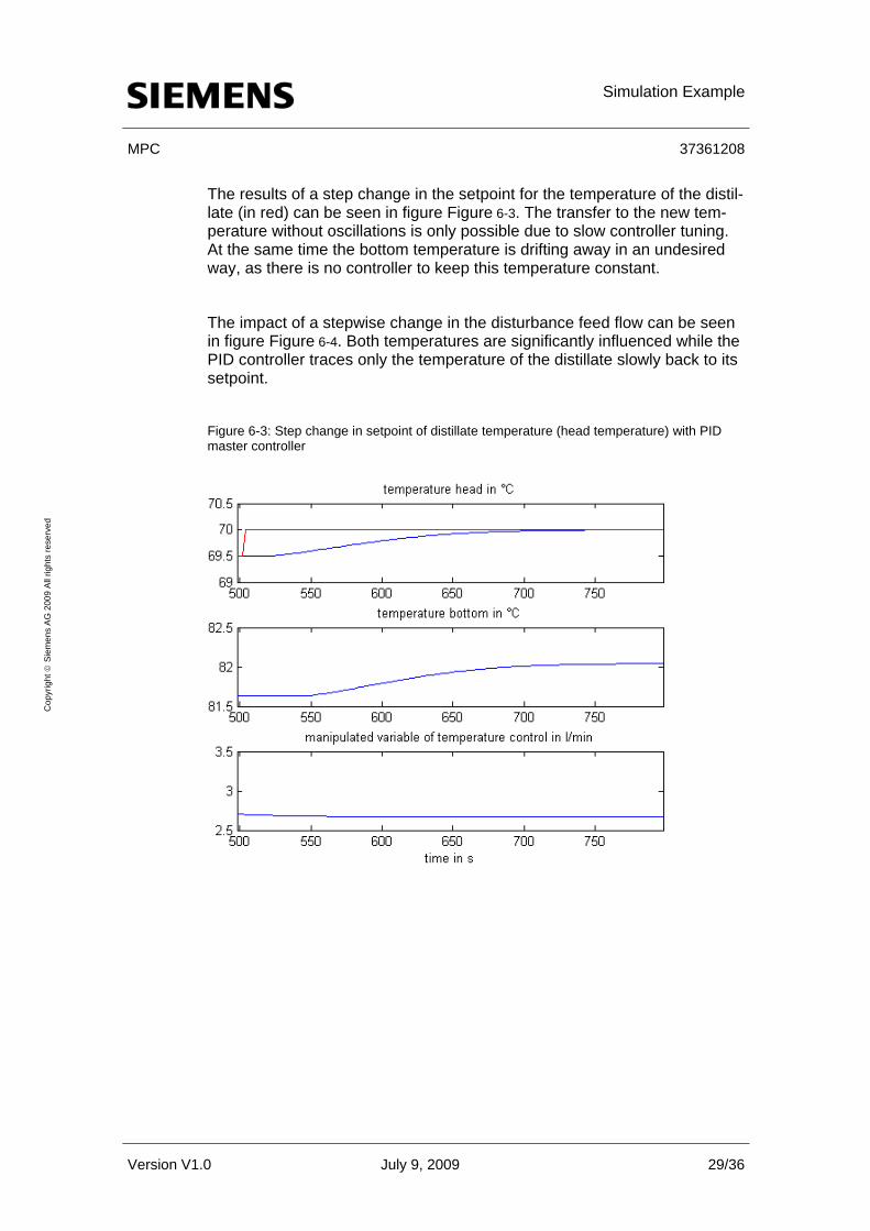
The results of a step change in the setpoint for the temperature of the distil-late (in red) can be seen in figure Figure 6-3. The transfer to the new tem-perature without oscillations is only possible due to slow controller tuning. At the same time the bottom temperature is drifting away in an undesired way, as there is no controller to keep this temperature constant.
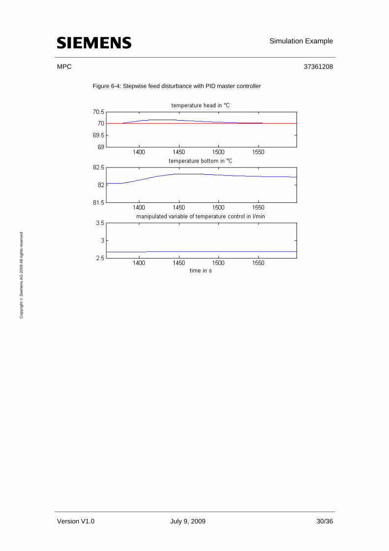
The impact of a stepwise change in the disturbance feed flow can be seen in figure Figure 6-4. Both temperatures are significantly influenced while the PID controller traces only the temperature of the distillate slowly back to its setpoint.
Figure 6-3: Step change in setpoint of distillate temperature (head temperature) with PID master controller
Version V1.0 July 9, 2009 29/36
Cop
yrig
ht ©
Sie
men
s A
G 2
009
All
right
s re
serv
ed
Simulation Example
MPC 37361208
Figure 6-4: Stepwise feed disturbance with PID master controller
Version V1.0 July 9, 2009 30/36
Cop
yrig
ht ©
Sie
men
s A
G 2
009
All
right
s re
serv
ed

Simulation Example
MPC 37361208
6.3 Control via MPC
In the following temperature control via MPC is considered.
Figure 6-5: Automation with MPC
Version V1.0 July 9, 2009 31/36
Cop
yrig
ht ©
Sie
men
s A
G 2
009
All
right
s re
serv
ed
Based on the measured temperatures of head and bottom and the known perturbation by feed flow the MPC calculates external setpoints for two slave PID controllers, which control the reflux and the heating vapor flow.
The results during a setpoint step change in the head temperature using the MPC are shown in figure Figure 6-6. The distillate temperature is ad-justed rapidly and without oscillation while the bottom temperature remains at its original level.

Simulation Example
MPC 37361208
Figure 6-6: Step changes in head temperature setpoint of using MPC
Version V1.0 July 9, 2009 32/36
Cop
yrig
ht ©
Sie
men
s A
G 2
009
All
right
s re
serv
ed
The same disturbance scenario as before using the PID controller is done with the MPC too. The results are shown in figure Figure 6-7. The distur-bance is compensated almost ideally with nearly no drift in the temperature signals.
Note For easy comparison, the ordinate scale and the length of the abscissa are the same in all diagrams.

Simulation Example
MPC 37361208
Figure 6-7: Stepwise feed disturbance using the MPC
Version V1.0 July 9, 2009 33/36
Cop
yrig
ht ©
Sie
men
s A
G 2
009
All
right
s re
serv
ed
The advantages of the MPC compared to the PID master controller can be seen clearly. By considering the multivariable case the thermodynamic in-teraction between head and bottom of the column is taken into account. Due to the feedforward of the measureable disturbance the perturbing in-fluence of the feed load can be compensated. The present example is based on a process with dead times and therefore the MPC can reach its goals faster (without oscillations) than the PID controller.
Conclusion
MPC 37361208
Version V1.0 July 9, 2009 34/36
Cop
yrig
ht ©
Sie
men
s A
G 2
009
All
right
s re
serv
ed
7 Conclusion
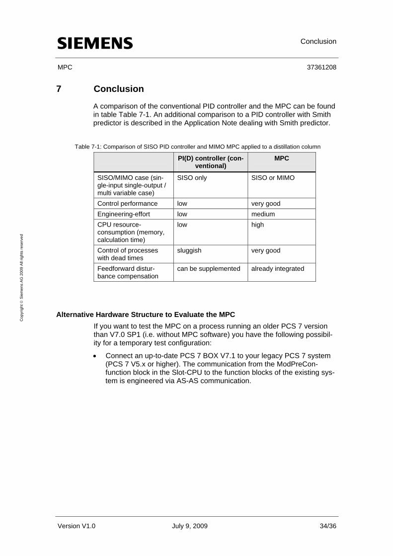
A comparison of the conventional PID controller and the MPC can be found in table Table 7-1. An additional comparison to a PID controller with Smith predictor is described in the Application Note dealing with Smith predictor.
Table 7-1: Comparison of SISO PID controller and MIMO MPC applied to a distillation column
PI(D) controller (con-ventional)
MPC
SISO/MIMO case (sin-gle-input single-output / multi variable case)
SISO only SISO or MIMO
Control performance low very good Engineering-effort low medium CPU resource-consumption (memory, calculation time)
low high
Control of processes with dead times
sluggish very good
Feedforward distur-bance compensation
can be supplemented already integrated
Alternative Hardware Structure to Evaluate the MPC If you want to test the MPC on a process running an older PCS 7 version than V7.0 SP1 (i.e. without MPC software) you have the following possibil-ity for a temporary test configuration:
• Connect an up-to-date PCS 7 BOX V7.1 to your legacy PCS 7 system (PCS 7 V5.x or higher). The communication from the ModPreCon-function block in the Slot-CPU to the function blocks of the existing sys-tem is engineered via AS-AS communication.

Conclusion
MPC 37361208
Figure 7-1: Test configuration for temporary evaluation of APC functionalities
Version V1.0 July 9, 2009 35/36
Cop
yrig
ht ©
Sie
men
s A
G 2
009
All
right
s re
serv
ed
PCS 7 OS ClientsPCS 7Engineering Station
PCS 7OS-Server (redundant)
PCS 7ControllerAS 414FHAS 417FH
ET 200M(Safety)
ET 200M
DP/PA-Link
PCS 7ControllerAS 414AS 416AS 417
ET 200M
ET 200M
Profibus PA
Prof
ibus
DP
Prof
ibus
DP
PCS 7 BOX(V7.1)
APC(MPC)
Legacy system SIMATIC PCS 7 (older than version V7.0 SP1)
Legacy system SIMATIC PCS 7 (older than version V7.0 SP1)
SIMATIC PCS 7 BOX (version V7.1) as „APC-
extension“
SIMATIC PCS 7 BOX (version V7.1) as „APC-
extension“
AS-AS CommunicationAS-AS Communication

History
MPC 37361208
Version V1.0 July 9, 2009 36/36
Cop
yrig
ht ©
Sie
men
s A
G 2
009
All
right
s re
serv
ed
8 History Table 8-1 History
Version Date Modification
V1.0 July 2009 1st release
9 Literature
[1.] Pfeiffer, B.-M., Lorenz, O.: Unit-orientierte Musterlösungen für Ad-vanced Control (Unit-oriented solution templates for advanced control) – Beispiel Destillationskolonne (Example distillation column). Automati-on 2008, Baden-Baden. VDI-Berichte 2032, S. 11-14, VDI-Verlag, Düs-seldorf.