multistage amplifiers - ee.hacettepe.edu.trusezen/ele315/multistage-1p.pdf · ac coupled multistage...
TRANSCRIPT
Multistage Amplifiers
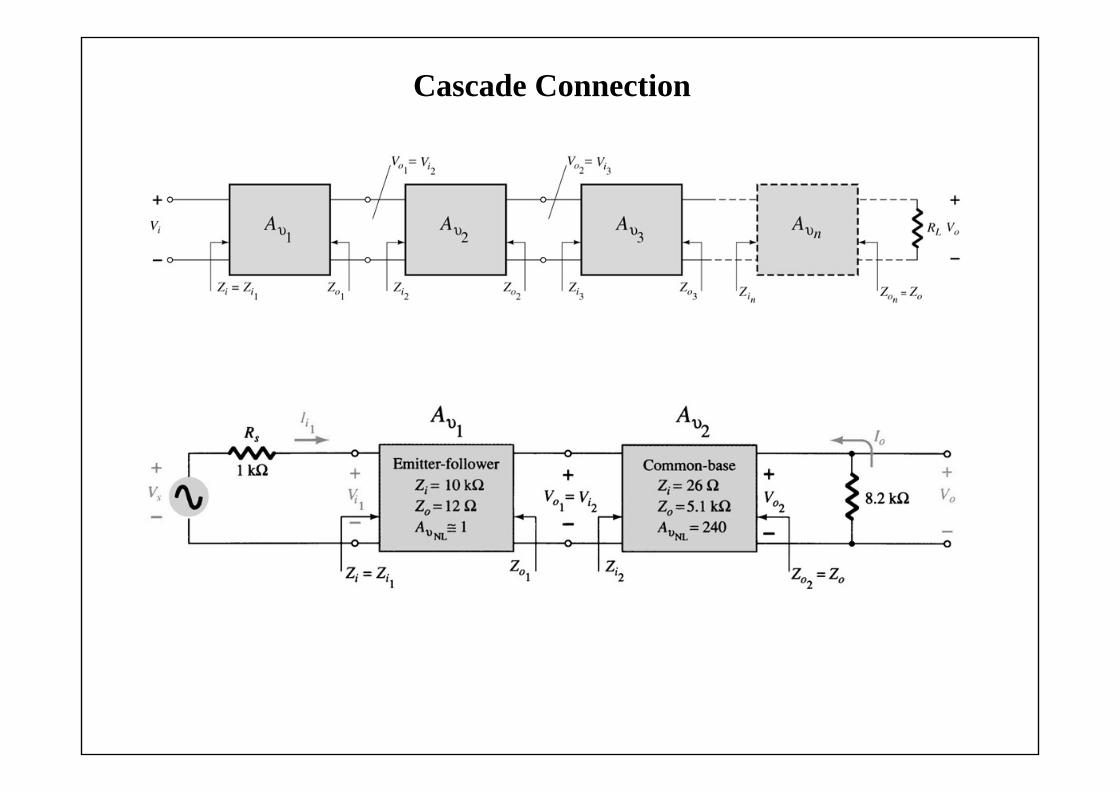
Cascade Connection

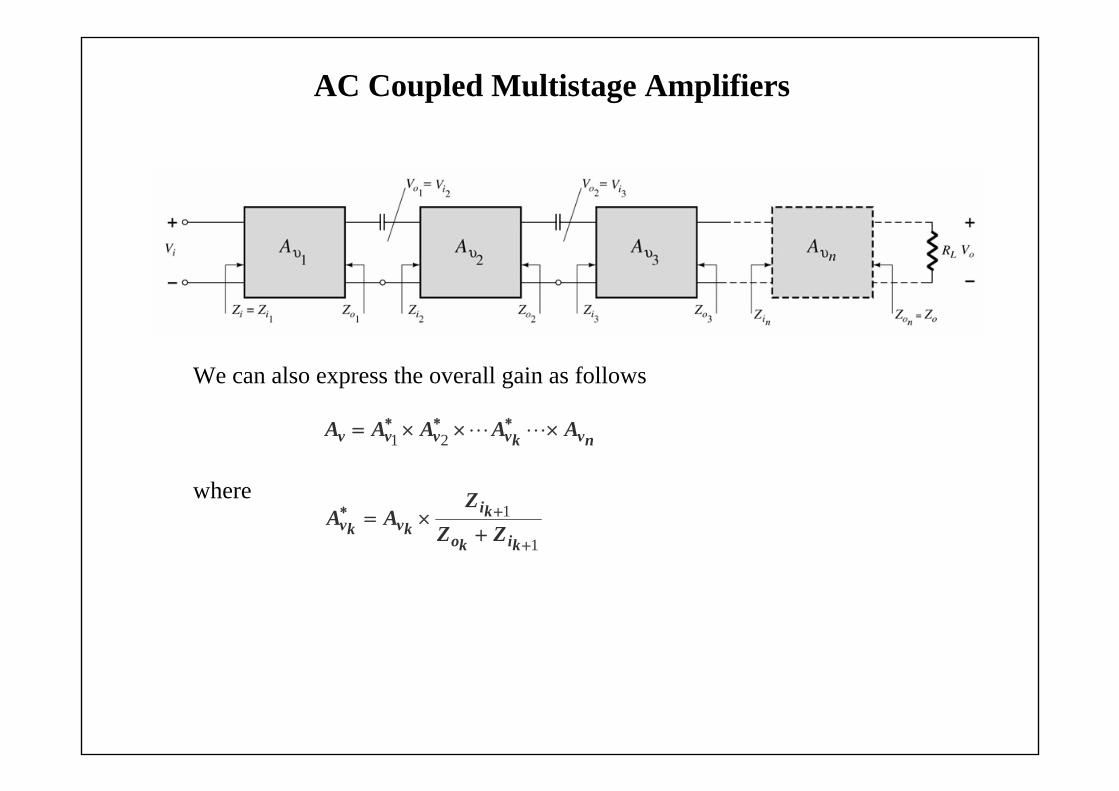
AC Coupled Multistage Amplifiers
The output of one amplifier is the input to the next amplifier.
Note the DC bias circuits are isolated from each other by the coupling capacitors.
The DC calculations are independent of the cascading. The AC calculations for gain and impedance are interdependent.
The overall gain:
with and 1ii ZZ
nvnino
nikv
kiko
kiv
io
ivv A
ZZZ
AZZ
ZA
ZZZ
AA
11
221
21
noo ZZ
AC Coupled Multistage Amplifiers
We can also express the overall gain as follows
where
1
1
kiko
kikvkv ZZ
ZAA
nvkvvvv AAAAA 21
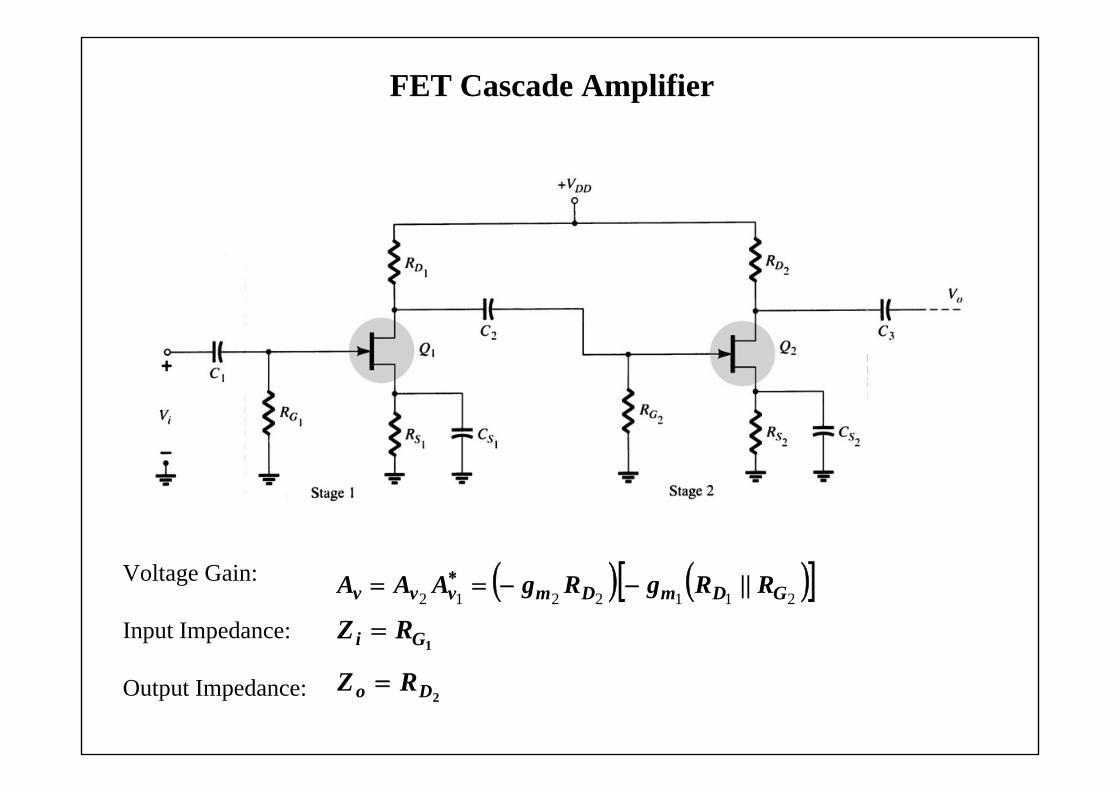
FET Cascade Amplifier
Voltage Gain:
Input Impedance:
Output Impedance:
2112212
GDmDmvvv RRgRgAAA ||
1Gi RZ
2Do RZ
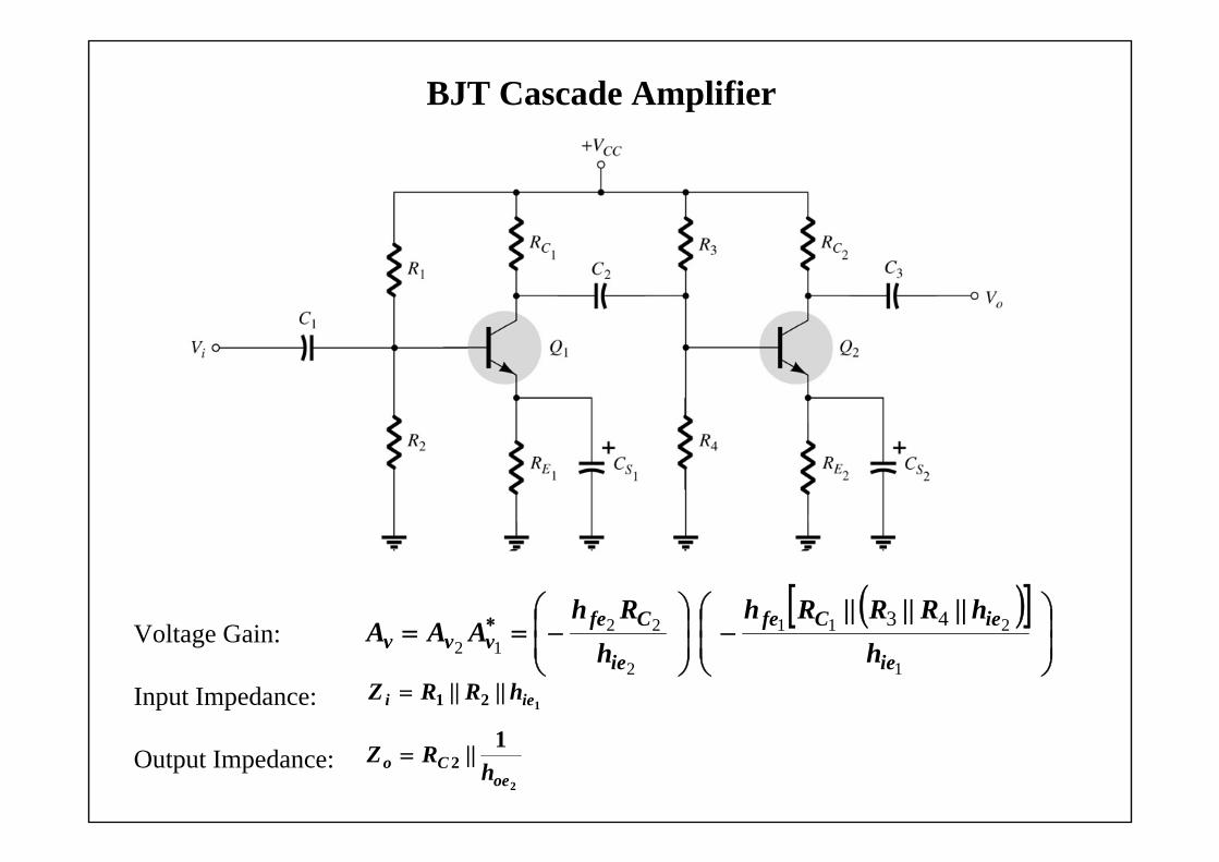
BJT Cascade Amplifier
Voltage Gain:
Input Impedance:
Output Impedance:
1
211
2
2212
43
ie
ieCfe
ie
Cfevvv h
h||R||R||Rhh
RhAAA
1 21 iei h||R||RZ
2
1 2oe
Co h||RZ
Combination of FET and BJT Cascade
A FET-BJT cascade is calculated in a similar fashion as a FET-FET or a BJT-BJT cascade.
This combination provides a high gain from the BJT with the high input impedance from the FET.
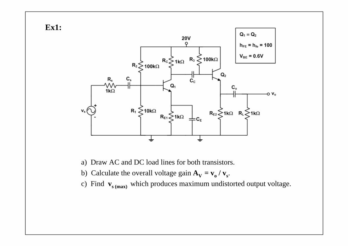
Ex1:
a) Draw AC and DC load lines for both transistors.b) Calculate the overall voltage gain AV = vo / vs. c) Find vs (max) which produces maximum undistorted output voltage.
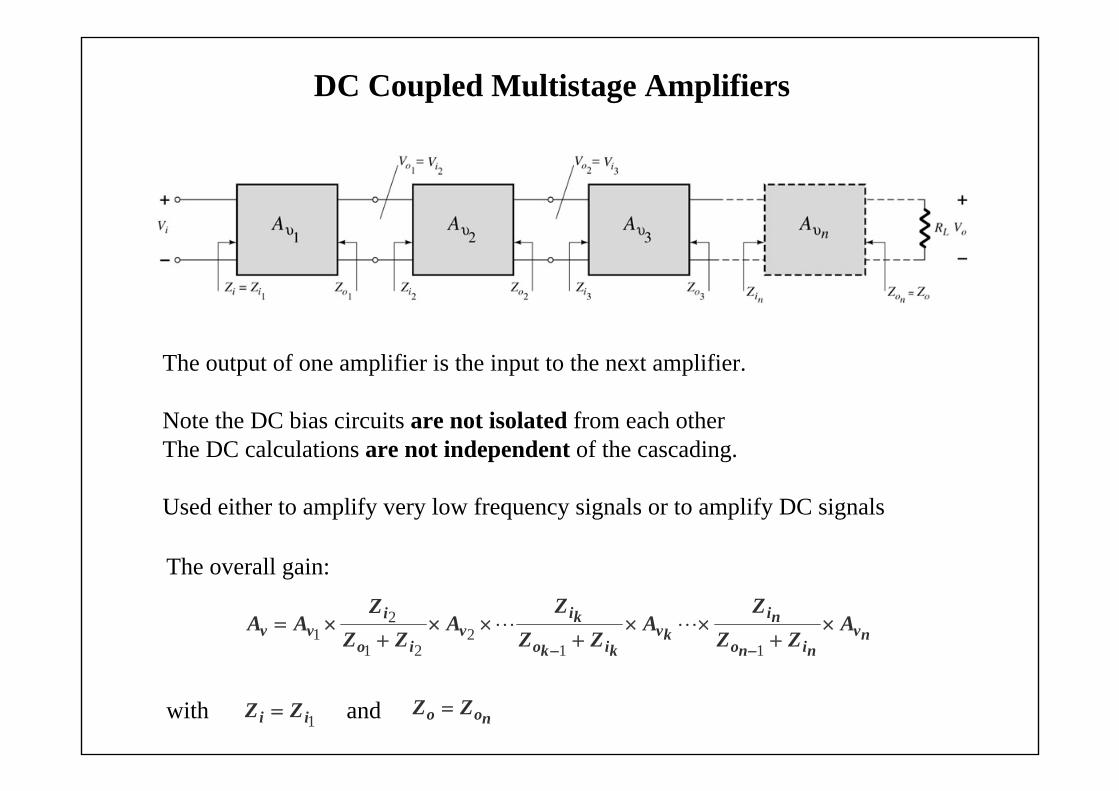
DC Coupled Multistage Amplifiers
The output of one amplifier is the input to the next amplifier.
Note the DC bias circuits are not isolated from each other The DC calculations are not independent of the cascading.
Used either to amplify very low frequency signals or to amplify DC signals
The overall gain:
with and 1ii ZZ
nvnino
nikv
kiko
kiv
io
ivv A
ZZZ
AZZ
ZA
ZZZ
AA
11
221
21
noo ZZ
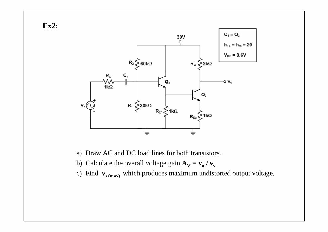
Ex2:
a) Draw AC and DC load lines for both transistors.b) Calculate the overall voltage gain AV = vo / vs. c) Find vs (max) which produces maximum undistorted output voltage.
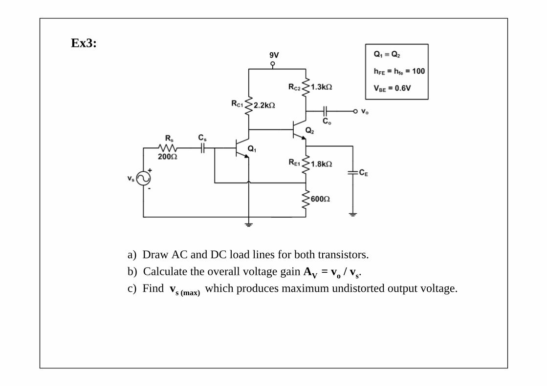
Ex3:
a) Draw AC and DC load lines for both transistors.b) Calculate the overall voltage gain AV = vo / vs. c) Find vs (max) which produces maximum undistorted output voltage.
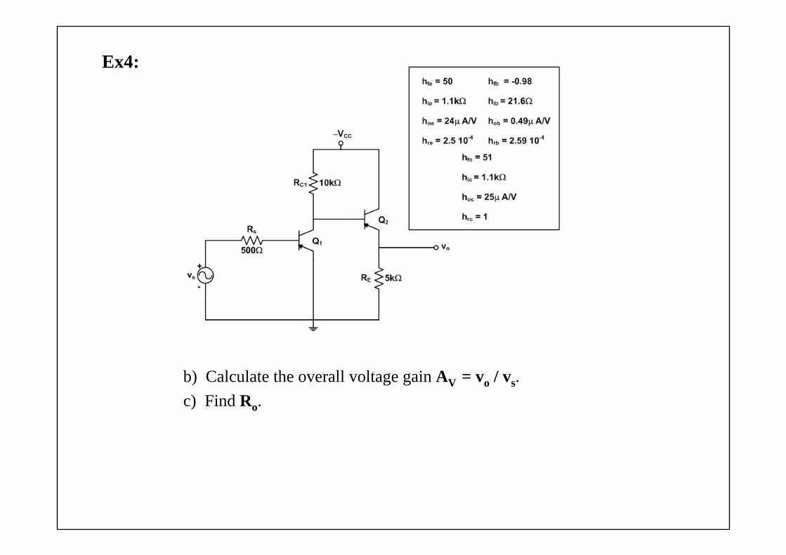
Ex4:
b) Calculate the overall voltage gain AV = vo / vs. c) Find Ro.
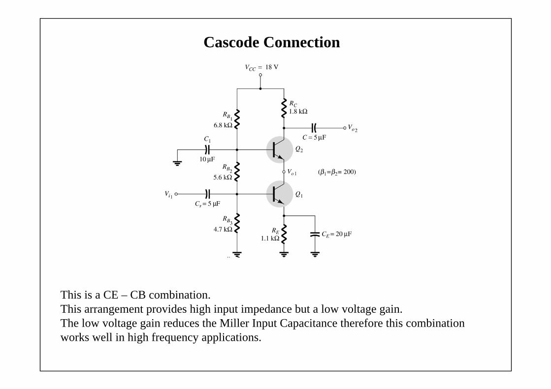
Cascode Connection
This is a CE – CB combination. This arrangement provides high input impedance but a low voltage gain.The low voltage gain reduces the Miller Input Capacitance therefore this combination works well in high frequency applications.
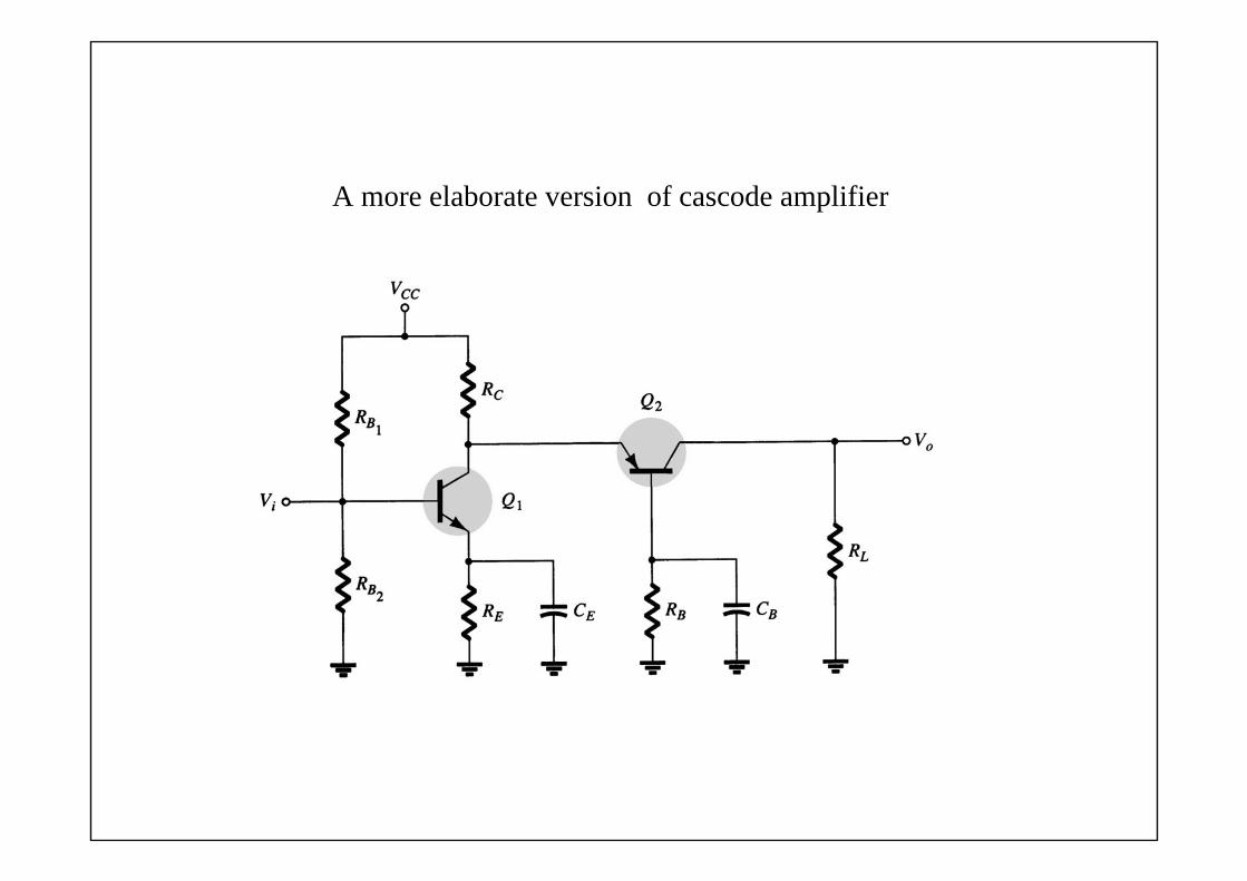
A more elaborate version of cascode amplifier
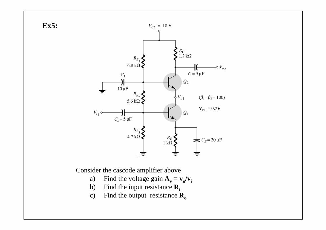
Consider the cascode amplifier abovea) Find the voltage gain Av = vo/vib) Find the input resistance Ric) Find the output resistance Ro
VBE = 0.7V
Ex5:
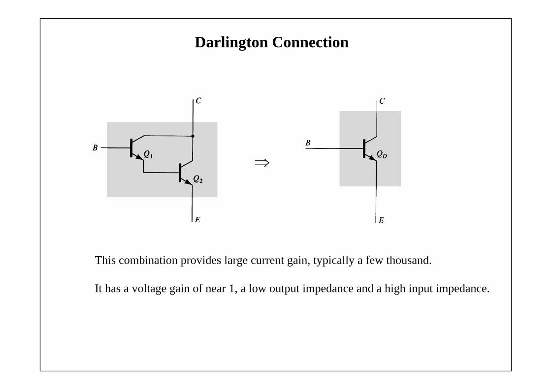
Darlington Connection
This combination provides large current gain, typically a few thousand.
It has a voltage gain of near 1, a low output impedance and a high input impedance.

Feedback Pair
This is a two-transistor circuit that operates like a Darlington pair.It has similar characteristics: high current gain, voltage gain of near 1, low output impedance and high input impedance.Note: it is not the Darlington configuration:
Darlington: 2 npn BJTsFeedback Pair: pnp driving an npn BJT