multiscale moment-based painterly rendering -...
TRANSCRIPT

Multiscale Moment-Based Painterly Rendering
Diego Nehab1 Luiz Velho2
1PUC-Rio – Pontifıcia Universidade Catolica, Rio de Janeiro2IMPA – Instituto de Matematica Pura e Aplicada
[email protected] [email protected]
Abstract
In this paper we present a new method for painterly rendering ofimages. Our method extends the image-moment stroke placementalgorithm in two ways: we employ a multiscale scheme for com-puting strokes and we provide a parametrized mechanism for con-trolling stroke distribution. In addition, we introduce a flexible im-plementation framework based on the extension language Lua.
Keywords: Non-photoralistic rendering, Painting, Dithering, Lua
1 Introduction
The evolution of computer graphics led naturally to the develop-ment of different types of visualization techniques. Initially, thefocus was on photorealistic rendering, where the goal is to gen-erate synthetic images that are indistinguishable from real pho-tographs [17]. More recently, there has been a growing interest innon-photorealistic rendering techniques that emphasize the expres-sive depiction of visual information [3].
Non-photorealistic rendering is, by definition, a very broad areaof research that encompasses many rendering styles in various ap-plication contexts. Two useful criteria for classification of non-photorealistic rendering techniques are: the type of source data;and the nature of the simulated process.
Techniques are classified according to source data into object-space methods that use the 3D model of a scene to create the ren-dered image [11, 14], and image-space methods that work directlyon the 2D image [4, 5]. Hybrid methods take advantage of both 3Dand 2D data to produce the final result [9].
Most non-photorealistic techniques are inspired in traditional vi-sual art forms, such as painting (oil [5], watercolor [1, 18]), drawing(pen-and-ink [7, 2, 22], pencil [19, 21], charcoal [23]), and printing(etching, engraving [12, 13]). Here, both the physical process andthe medium provide a paradigm for computation and interaction.
In this paper we present a new method for painterly rendering ofimages that improves upon previous work in the area.
1.1 Related Work
Painterly rendering simulates the appearance of painted images.The basic primitive in this technique is a brush stroke. Images aregenerated by applying a sequence of brush strokes to a 2D canvas.A brush stroke has various attributes, such as position, shape andcolor [20].
In object-space methods, brush strokes are first associated withthe 3D geometry of objects in a scene, and then projected to the im-age plane defined by a virtual camera [11]. In image-space meth-ods, brush strokes are placed on the output image, based on 2Dinformation derived from input images [4].
Interactive methods allow the user to guide the rendering pro-cess in a manual or semi-automatic manner, by indicating wherestrokes should placed [4]. Non-interactive methods render the im-age automatically based on input parameters and data analysis [5].
Some methods process a sequence of images exploiting temporalcoherence [10, 6].
The technique described in this paper is a non-interactive, image-space method. It is based on the image moment-based strokeplacement algorithm [15, 16]. The main original contributions inour work are: a multiscale scheme for computing the strokes, aparametrized mechanism for controlling stroke distribution, an im-age abstraction specially optimized for the algorithm, and a flex-ible implementation framework based on the extension languageLua [8].
1.2 Overview
This paper is organized as follows. Section 2 reviews the moment-based painterly rendering method. Section 3 describes the additionsproposed in the new method. Section 4 shows some results of usingthe method. Section 5 concludes with final remarks and a discus-sion of ongoing work.
2 Review of the image-moment basedpainterly rendering
Given a source image and a stroke template image, the painterlyrendering algorithm outputs a painted version of the source image.The method proceeds as an artist who progressively strokes a can-vas trying to reproduce the source image on it.
In this paper, we use gray-scale images, but the method presentedextends naturally to color images.
------------------------------------------------------------------------ Painterly renders an image-- Input-- Source: source image-- Stroke: stroke template image-- S: neighborhood size-- Output-- painted version of source image----------------------------------------------------------------------function PainterlyRender(Source, Stroke, S)
local List = ComputeStrokeList(Source, S)local w, h = GetWidth(Source), GetHeight(Source)return PaintStrokeList(Stroke, List, Canvas(w, h))
end
Program 1: Painterly rendering algorithm.
The process can be divided into two phases: analysis and syn-thesis. In the analysis phase, a list of strokes is calculated from thesource image. In the synthesis phase, the strokes are painted over ablank canvas. Both phases can be seen in Program 1.
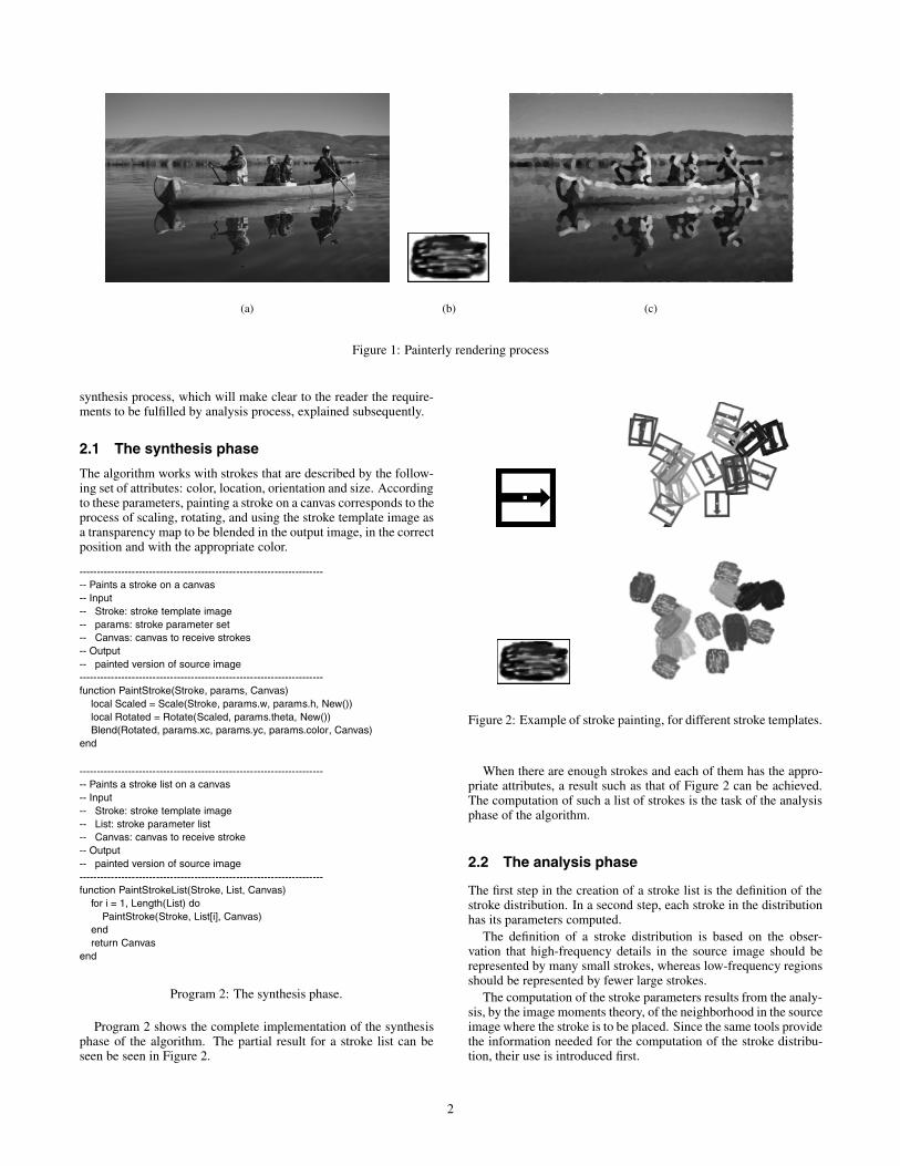
The algorithm outlined above, and detailed in the following sec-tions, generates images similar to that shown in Figure 1, and is theresult of previous work [16]. We proceed with the description of the
(a) (b) (c)
Figure 1: Painterly rendering process
synthesis process, which will make clear to the reader the require-ments to be fulfilled by analysis process, explained subsequently.
2.1 The synthesis phase
The algorithm works with strokes that are described by the follow-ing set of attributes: color, location, orientation and size. Accordingto these parameters, painting a stroke on a canvas corresponds to theprocess of scaling, rotating, and using the stroke template image asa transparency map to be blended in the output image, in the correctposition and with the appropriate color.
------------------------------------------------------------------------ Paints a stroke on a canvas-- Input-- Stroke: stroke template image-- params: stroke parameter set-- Canvas: canvas to receive strokes-- Output-- painted version of source image----------------------------------------------------------------------function PaintStroke(Stroke, params, Canvas)
local Scaled = Scale(Stroke, params.w, params.h, New())local Rotated = Rotate(Scaled, params.theta, New())Blend(Rotated, params.xc, params.yc, params.color, Canvas)
end
------------------------------------------------------------------------ Paints a stroke list on a canvas-- Input-- Stroke: stroke template image-- List: stroke parameter list-- Canvas: canvas to receive stroke-- Output-- painted version of source image----------------------------------------------------------------------function PaintStrokeList(Stroke, List, Canvas)
for i = 1, Length(List) doPaintStroke(Stroke, List[i], Canvas)
endreturn Canvas
end
Program 2: The synthesis phase.
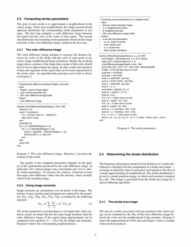
Program 2 shows the complete implementation of the synthesisphase of the algorithm. The partial result for a stroke list can beseen be seen in Figure 2.
Figure 2: Example of stroke painting, for different stroke templates.
When there are enough strokes and each of them has the appro-priate attributes, a result such as that of Figure 2 can be achieved.The computation of such a list of strokes is the task of the analysisphase of the algorithm.
2.2 The analysis phase
The first step in the creation of a stroke list is the definition of thestroke distribution. In a second step, each stroke in the distributionhas its parameters computed.
The definition of a stroke distribution is based on the obser-vation that high-frequency details in the source image should berepresented by many small strokes, whereas low-frequency regionsshould be represented by fewer large strokes.
The computation of the stroke parameters results from the analy-sis, by the image moments theory, of the neighborhood in the sourceimage where the stroke is to be placed. Since the same tools providethe information needed for the computation of the stroke distribu-tion, their use is introduced first.
2
2.3 Computing stroke parameters
The goal of each stroke is to approximate a neighborhood of thesource image. From each neighborhood, the image-moment basedapproach determines the corresponding stroke parameters in twosteps. The first step computes a color difference image betweenthe region and the color at the center of that region. The secondstep determines the remaining stroke parameters based on the imagemoments of the color difference image created in the first step.
2.3.1 The color difference image
The color difference image attempts to measure the distance be-tween the color of the stroke and the color of each point in thesource image neighborhood being considered. Ideally, the resultingimage shows a picture of the shape that a stroke of that color shouldhave if was to approximate the region. In other words, the operationisolates the segments of the region that can be better represented inthe stroke color. An algorithm that generates such result is shownin Program 3.
------------------------------------------------------------------------ Computes the difference between Region and color-- Input-- Region: source image region-- color: stroke parameter list-- Diff: color difference image buffer-- Output-- color difference image----------------------------------------------------------------------function ColorDifferenceImage(Region, color, Diff)
local d0 = 0.2local f = function(d)
if d < d0 then return (1 - (d/d0)ˆ2)ˆ2else return 0 end
endClear(Diff, 0)for x = 0, GetWidth(Region)-1 do
for y = 0, GetHeight(Region)-1 dolocal d = abs(color - GetColor(Region, x, y))SetColor(Diff, x, y, f(d)) end
endendreturn Diff
end
Program 3: The color difference image. Function f increases thecontrast of the result.
The quality of the computed parameters depends on the qual-ity of the segmentation produced by the color difference image. Inparticular, low contrast images may consistently give rise to simi-lar stroke parameters. To increase the contrast, a function is usedthat maps color difference values into the intensity values actuallystored in the resulting image.
2.3.2 Using image moments
Image moments are summations over all pixels of the image. Thenotions of area, position and orientation are captured by the quanti-ties M00, M01, M10, M11, M20, M02 , as defined by the followingequation:
Mim =
X
x
X
y
xlymI(x; y) (1)
The stroke parameters corresponding to a rectangle that, when ren-dered, creates an image that has the same image moments than thecolor difference image of the region being approximated can becomputed from equation (1) — See [16] for details and formulas.Program 4 shows the corresponding implementation.
------------------------------------------------------------------------ Computes stroke parameters for a neighborhood-- Input-- Source: stroke template image-- x, y: neighborhood center-- S: neighborhood size-- Diff: color difference image buffer-- Output-- a set with the parameters:-- xc, yc: center of stroke-- color: stroke color-- w, h: stroke size-- theta: stroke orientation----------------------------------------------------------------------function StrokeParameters(Source, x, y, S, Diff)
local Region = Share(Source, x, y, S, S, New())local color = GetColor(Source, x, y)ColorDifferenceImage(Region, color, Diff)local m00, m01, m10, m11, m02, m20 = Moments(Diff)if m00 < S*S/100 then return nil endlocal dxc = m10/m00;local dyc = m01/m00;local a = m20/m00 - dxc*dxc;local b = 2*(m11/m00 - dxc*dyc);local c = m02/m00 - dyc*dyc;local t1 = a - clocal theta = atan2(b, t1) / 2;local t2 = sqrt(b*b + t1*t1);local t3 = a+cif t3 + t2 < 0 then return nil endlocal w = sqrt(6 * (t3 + t2));if t3 - t2 < 0 then return nil endlocal h = sqrt(6 * (t3 - t2));local xc = x + floor(dxc - S/2 + 0.5);local yc = y + floor(dyc - S/2 + 0.5);if w < 1 or h < 1 then return nil endreturn f xc = xc, yc = yc, w = w, h = h, theta = theta, color = color g
end
Program 4: The stroke parameters.
2.4 Determining the stroke distribution
The frequency information needed for the definition of a stroke dis-tribution is obtained with the computation of a stroke area image —an image in which the value of each pixel corresponds to the area ofa stroke approximating its neighborhood. The stroke distribution isgiven by a stroke positions image, in which each position is markedby a dot. This image is generated from the stroke area image by aspecial dithering algorithm.
2.4.1 The stroke area image
The area of a stroke associated with any position in the source im-age can be estimated by the M00 of the color difference image be-tween the color and the neighborhood of the position. Program 5shows the implementation of this idea and Figure 3 shows a sampleof the result it produces.
3

------------------------------------------------------------------------ Computes the stroke area image-- Input-- Source: source image-- S: neighborhood size-- Output-- stroke are image----------------------------------------------------------------------function StrokeAreaImage(Source, S)
local w, h = GetWidth(Source), GetHeight(Source)local Output = BlankCanvas(w, h)local Diff = BlankCanvas(S, S)local Region = New()for y = 0, h-1 do
for x = 0, w-1 doShare(Source, x, y, S, S, Region)local wr, hr = GetWidth(Region), GetHeight(Region)ColorDifferenceImage(Region, GetColor(Source, x, y), Diff)SetColor(Output, x, y, Moment00(Diff, wr, hr)/(wr*hr))
endendreturn Output
end
Program 5: The stroke area image.
Figure 3: Example of stroke area image.
2.4.2 The stroke positions image
The stroke positions image is a monochrome dithered version ofthe stroke area image. The algorithm used to create the stroke dis-tribution must be designed to concentrate strokes around the darkregions of the stroke area image, and to avoid large regions with-out strokes. To this end, the original study used a modified versionof a space-filling curve dithering algorithm, in which the accumu-lated intensity values were inversely proportional to the area of thestroke.
Figure 4: Example of stroke positions image.
Figure 4 shows an example of how the stroke positions imageshould look. This image was created from the stroke area image ofFigure 3 by our own parametrized dithering algorithm. This newalgorithm will be explained in due time, in Section 3.
2.4.3 Computing the stroke list
Completing the implementation of the painterly rendering algo-rithm, Program 6 shows the procedure used to compute the strokelist. The only addition to what was previously discussed is that, be-fore being returned to the caller, the stroke list is sorted by strokearea. This is to prevent fine details, represented by small strokes,from being overwritten by larger strokes.
------------------------------------------------------------------------ Returns a list of strokes-- Input-- Source: stroke template image-- S: neighborhood size-- Output-- a list with strokes, sorted by order----------------------------------------------------------------------function ComputeStrokeList(Source, S)
local List = fglocal w, h = GetWidth(Source), GetHeight(Source)local Area = StrokeAreaImage(Source, S)local Position = Dither(Area, S)local Diff = Alloc(S, S, New())for y = 0, h-1 do
for x = 0, w-1 doif GetColor(Position, x, y) == 0 then
Append(List, StrokeParameters(Source, x, y, S, Diff))end
endendSort(List, function(a,b) return a.w*a.h > b.w*b.h end)return List
end
Program 6: The stroke list.
3 Original contributions to the algorithm
The ideas presented so far describe a complex process to createimages that resembles human hand painting, as seen in Figure 1.Some aspects of the process can be improved, other parts can beimplemented in a way that deserves documentation. This sessiondescribes what was added by our research.
3.1 Multi-resolution analysis
As expected, the stroke parameters, computed with the aid of thecolor difference images and the image moments theory, correctlyapproximate local source image neighborhoods. Unfortunately, al-though small details can be captured within a neighborhood, fea-tures that ocupy more than the size of a single neighborhood cannot,and must therefore be represented by a group of smaller strokes.Unless the used stroke template image has a low opacity overall,this composition becomes evident. Furthermore, a needlessly largeamount of small strokes must be used to represent what could beapproximated by fewer large strokes.
In order to capture strokes over a wider range of sizes, we usea multi-resolution approach during the analysis phase of the algo-rithm. Stroke lists are collected for each resolution in a pyramidbuilt from the source image. The painted result at each level is ob-tained by blending its strokes over the result of the lower resolutionlevel. Program 7 shows the implementation of these ideas.
4

(a) Level 1 (b) Level 2
(c) Level 3 (d) Level 4
Figure 5: Strokes at different resolution levels.
------------------------------------------------------------------------ Painterly renders an image, with multi-resolution-- Input-- Source: source image-- Stroke: stroke template image-- S: neighborhood size-- L: number of levels-- Output-- painted version of source image----------------------------------------------------------------------function MultiResolutionPainterlyRender(Source, Stroke, S, L)
local Pyramid = Sourcelocal l = 2while l < = L do
local w, h = GetWidth(Pyramid[l-1])/2, GetHeight(Pyramid[l-1])/2Pyramid[l] = Copy(Scale(Pyramid[l-1], w, h, New()), New())l = l + 1
endlocal Canvas = BlankCanvas(GetWidth(Pyramid[L])/2,
GetHeight(Pyramid[L])/2)l = Lwhile l >= 1 do
local w, h = GetWidth(Pyramid[l]), GetHeight(Pyramid[l])Canvas = Copy(Scale(Canvas, w, h, New()), New())local Sp, E = Spread(S, L, l), Enhance(S, L, l)local List = ExtendedStrokeList(Pyramid[l], S, Sp, E)Canvas = PaintStrokeList(Stroke, List, Canvas)l = l - 1
endreturn Canvas
end
Program 7: The multi-resolution painter algorithm.
(a) Level 6
Figure 6: Composition of strokes at different resolution levels.
Figure 6 shows an example of painterly rendered image cre-ated by the multi-resolution method. Figures 5(a) to (d) depict thestrokes at each resolution level that are composed together to cre-ate the final image in Figure 6. The strokes were generated fromblurred images coming from the multiresolution pyramid. The im-ages are shown scaled to the same resolution to simplify compari-son, and to illustrate the steps followed by the algorithm.
5
(a) s: 6, e: 3 (b) s: 6, e: 6 (c) s: 6, e: 9
(d) s: 14, e: 5 (e) s: 14, e: 11 (f) s: 14, e: 14
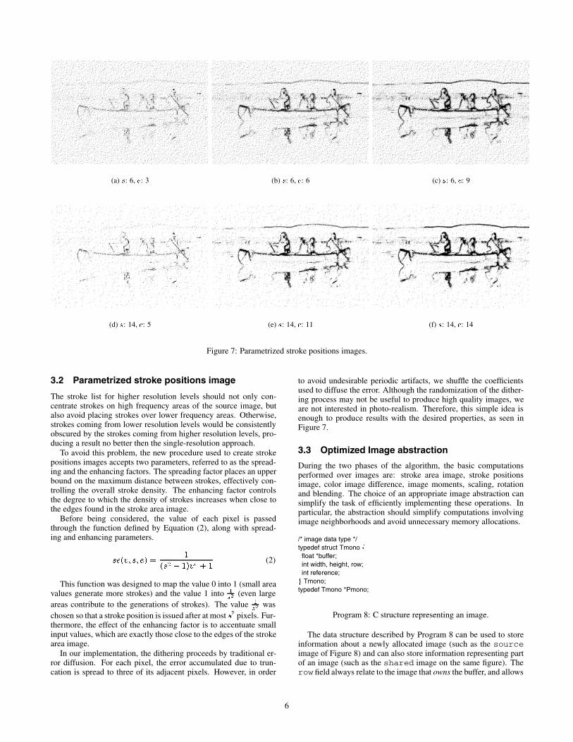
Figure 7: Parametrized stroke positions images.
3.2 Parametrized stroke positions image
The stroke list for higher resolution levels should not only con-centrate strokes on high frequency areas of the source image, butalso avoid placing strokes over lower frequency areas. Otherwise,strokes coming from lower resolution levels would be consistentlyobscured by the strokes coming from higher resolution levels, pro-ducing a result no better then the single-resolution approach.
To avoid this problem, the new procedure used to create strokepositions images accepts two parameters, referred to as the spread-ing and the enhancing factors. The spreading factor places an upperbound on the maximum distance between strokes, effectively con-trolling the overall stroke density. The enhancing factor controlsthe degree to which the density of strokes increases when close tothe edges found in the stroke area image.
Before being considered, the value of each pixel is passedthrough the function defined by Equation (2), along with spread-ing and enhancing parameters.
se(v; s; e) =1
(s2 � 1)ve + 1(2)
This function was designed to map the value 0 into 1 (small areavalues generate more strokes) and the value 1 into 1
s2(even large
areas contribute to the generations of strokes). The value 1
s2was
chosen so that a stroke position is issued after at most s2 pixels. Fur-thermore, the effect of the enhancing factor is to accentuate smallinput values, which are exactly those close to the edges of the strokearea image.
In our implementation, the dithering proceeds by traditional er-ror diffusion. For each pixel, the error accumulated due to trun-cation is spread to three of its adjacent pixels. However, in order
to avoid undesirable periodic artifacts, we shuffle the coefficientsused to diffuse the error. Although the randomization of the dither-ing process may not be useful to produce high quality images, weare not interested in photo-realism. Therefore, this simple idea isenough to produce results with the desired properties, as seen inFigure 7.
3.3 Optimized Image abstraction
During the two phases of the algorithm, the basic computationsperformed over images are: stroke area image, stroke positionsimage, color image difference, image moments, scaling, rotationand blending. The choice of an appropriate image abstraction cansimplify the task of efficiently implementing these operations. Inparticular, the abstraction should simplify computations involvingimage neighborhoods and avoid unnecessary memory allocations.
/* image data type */typedef struct Tmono ffloat *buffer;int width, height, row;int reference;g Tmono;typedef Tmono *Pmono;
Program 8: C structure representing an image.
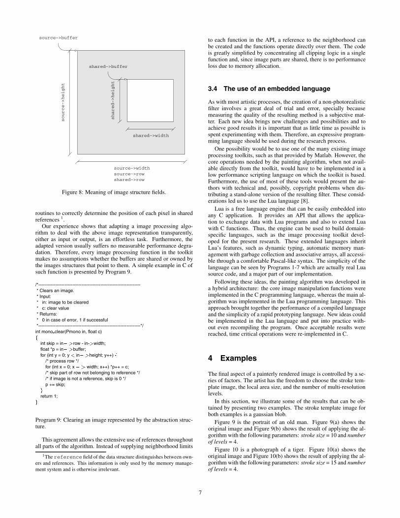
The data structure described by Program 8 can be used to storeinformation about a newly allocated image (such as the sourceimage of Figure 8) and can also store information representing partof an image (such as the shared image on the same figure). Therow field always relate to the image that owns the buffer, and allows
6
source−>widthsource−>rowshared−>row
source−>height
shared−>width
source−>buffer
shared−>buffer
shared−>height
Figure 8: Meaning of image structure fields.
routines to correctly determine the position of each pixel in sharedreferences 1.
Our experience shows that adapting a image processing algo-rithm to deal with the above image representation transparently,either as input or output, is an effortless task. Furthermore, theadapted version usually suffers no measurable performance degra-dation. Therefore, every image processing function in the toolkitmakes no assumptions whether the buffers are shared or owned bythe images structures that point to them. A simple example in C ofsuch function is presented by Program 9.
/*------------------------------------------------------------------* Clears an image.* Input:* in: image to be cleared* c: clear value* Returns:* 0 in case of error, 1 if successful*------------------------------------------------------------------*/int mono clear(Pmono in, float c)f
int skip = in� >row - in->width;float *p = in� >buffer;for (int y = 0; y < in� >height; y++) f
/* process row */for (int x = 0; x � > width; x++) *p++ = c;/* skip part of row not belonging to reference *//* if image is not a reference, skip is 0 */p += skip;
g
return 1;g
Program 9: Clearing an image represented by the abstraction struc-ture.
This agreement allows the extensive use of references throughoutall parts of the algorithm. Instead of supplying neighborhood limits
1The reference field of the data structure distinguishes between own-ers and references. This information is only used by the memory manage-ment system and is otherwise irrelevant.
to each function in the API, a reference to the neighborhood canbe created and the functions operate directly over them. The codeis greatly simplified by concentrating all clipping logic in a singlefunction and, since image parts are shared, there is no performanceloss due to memory allocation.
3.4 The use of an embedded language
As with most artistic processes, the creation of a non-photorealisticfilter involves a great deal of trial and error, specially becausemeasuring the quality of the resulting method is a subjective mat-ter. Each new idea brings new challenges and possibilities and toachieve good results it is important that as little time as possible isspent experimenting with them. Therefore, an expressive program-ming language should be used during the research process.
One possibility would be to use one of the many existing imageprocessing toolkits, such as that provided by Matlab. However, thecore operations needed by the painting algorithm, when not avail-able directly from the toolkit, would have to be implemented in alow performance scripting language on which the toolkit is based.Furthermore, the use of most of these tools would present the au-thors with technical and, possibly, copyright problems when dis-tributing a stand-alone version of the resulting filter. These consid-erations led us to use the Lua language [8].
Lua is a free language engine that can be easily embedded intoany C application. It provides an API that allows the applica-tion to exchange data with Lua programs and also to extend Luawith C functions. Thus, the engine can be used to build domain-specific languages, such as the image processing toolkit devel-oped for the present research. These extended languages inheritLua’s features, such as dynamic typing, automatic memory man-agement with garbage collection and associative arrays, all accessi-ble through a comfortable Pascal-like syntax. The simplicity of thelanguage can be seen by Programs 1-7 which are actually real Luasource code, and a major part of our implementation.
Following these ideas, the painting algorithm was developed ina hybrid architecture: the core image manipulation functions wereimplemented in the C programming language, whereas the main al-gorithm was implemented in the Lua programming language. Thisapproach brought together the performance of a compiled languageand the simplicity of a rapid prototyping language. New ideas couldbe implemented in the Lua language and put into practice with-out even recompiling the program. Once acceptable results werereached, time critical operations were re-implemented in C.
4 Examples
The final aspect of a painterly rendered image is controlled by a se-ries of factors. The artist has the freedom to choose the stroke tem-plate image, the local area size, and the number of multi-resolutionlevels.
In this section, we illustrate some of the results that can be ob-tained by presenting two examples. The stroke template image forboth examples is a gaussian blob.
Figure 9 is the portrait of an old man. Figure 9(a) shows theoriginal image and Figure 9(b) shows the result of applying the al-gorithm with the following parameters: stroke size = 10 and numberof levels = 4.
Figure 10 is a photograph of a tiger. Figure 10(a) shows theoriginal image and Figure 10(b) shows the result of applying the al-gorithm with the following parameters: stroke size = 15 and numberof levels = 4.
7

5 Conclusions
In this work, we introduced a multi-resolution approach to thepainterly rendering by local source image approximation method.The development of the research gave rise to a parametrized strokedistribution algorithm, easily implemented. The use of a high-levelprogramming language presented a satisfactory framework to speedup the development process. Finally, a specially designed imageabstraction simplified and optimized the implementation.
5.1 Future work
The image moment theory provides a powerful tool in the creationof local source image approximations. The quality of these approx-imations, however, is strongly dependent on the quality of the localcolor difference images. In a future work, we intend to investigatealternatives to the color difference images, attempting to producebetter controllable results.
The encoding and storage of stroke lists will also be studied. Bycompacting the information provided by the lists, it is possible torepresent painterly rendered images in a space efficient way. If thenew segmentation techniques lead to substantial improvements, itmay even be possible to encode photo-realistic images, transform-ing the scheme into an image compression algorithm.
Acknowledgments
This work was developed at the VISGRAF Laboratory of IMPA andTECGRAF of PUC-Rio.
We would like to thank Danilo Tuler de Oliveira and DiogoVieira Andrade who participate in the early stages of this research.
The authors are partially supported by research grants from theBrazilian Council for Scientific and Technological Development(CNPq) and Rio de Janeiro Research Foundation (FAPERJ).
References
[1] Cassidy J. Curtis, Sean E. Anderson, Joshua E. Seims,Kurt W. Fleischer, and David H. Salesin. Computer-generatedwatercolor. Proceedings of SIGGRAPH 97, pages pages 421–430, August 1997.
[2] Gershon Elber. Line Art Illustrations of Parametric and Im-plicit Forms. IEEE Transactions on Visualization and Com-puter Graphics, 4(1), January – March 1998. ISSN 1077-2626.
[3] Stuart Green, David Salesin, Simon Schofield, Aaron Hertz-mann, Peter Litwinowicz, Amy Gooch, Cassidy Curtis, andBruce Gooch. Non-Photorealistic Rendering. SIGGRAPH’99 Non-Photorealistic Rendering Course Notes, 1999.
[4] Paul E. Haeberli. Paint by numbers: Abstract image repre-sentations. Proceedings of SIGGRAPH 90, 24(4):207–214,August 1990.
[5] Aaron Hertzmann. Painterly rendering with curved brushstrokes of multiple sizes. Proceedings of SIGGRAPH 98,pages 453–460, July 1998. ISBN 0-89791-999-8. Held in Or-lando, Florida.
[6] Aaron Hertzmann and Ken Perlin. Painterly rendering forvideo and interaction. NPAR 2000 : First InternationalSymposium on Non Photorealistic Animation and Rendering,pages 7–12, June 2000.
[7] Aaron Hertzmann and Denis Zorin. Illustrating smooth sur-faces. Proceedings of SIGGRAPH 2000, July 2000. Held inNew Orleans, Louisianna.
[8] Roberto Ierusalimschy, Luiz Henrique de Figueiredo, andWaldemar Celes. Lua: an extensible extension language. Soft-ware: Practice & Experience, 26(6):635–652, 1996.
[9] Allison W. Klein, Wilmot W. Li, Michael M. Kazhdan, Wag-ner T. Correa, Adam Finkelstein, and Thomas A. Funkhouser.Non-photorealistic virtual environments. Proceedings of SIG-GRAPH 2000, pages 527–534, July 2000. ISBN 1-58113-208-5.
[10] Peter Litwinowicz. Processing images and video for an im-pressionist effect. Proceedings of SIGGRAPH 97, pages 407–414, August 1997. ISBN 0-89791-896-7. Held in Los Ange-les, California.
[11] Barbara J. Meier. Painterly rendering for animation. Proceed-ings of SIGGRAPH 96, pages 477–484, August 1996. ISBN0-201-94800-1. Held in New Orleans, Louisiana.
[12] Victor Ostromoukhov. Digital facial engraving. Proceedingsof SIGGRAPH 99, pages 417–424, August 1999. ISBN 0-20148-560-5. Held in Los Angeles, California.
[13] Yachin Pnueli and Alfred M. Bruckstein. Digdurer - a digitalengraving system. In The Visual Computer, volume 10, pages277–292, August 1994.
[14] Emil Praun, Hugues Hoppe, Matthew Webb, and AdamFinkelstein. Real-time hatching. Proceedings of SIGGRAPH2001, pages 579–584, August 2001. ISBN 1-58113-292-1.
[15] Michio Shiraishi and Yasushi Yamaguchi. Image moment-based stroke placement. Technical Report skapps3794, Uni-versity of Tokyo, Tokyo Japan, May 1999.
[16] Michio Shiraishi and Yasushi Yamaguchi. An algorithm forautomatic painterly rendering based on local source image ap-proximation. NPAR 2000 : First International Symposium onNon Photorealistic Animation and Rendering, pages 53–58,June 2000.
[17] Francois X. Sillion. The state of the art in physically-basedrendering and its impact on future applications. Second Eu-rographics Workshop on Rendering (Photorealistic Renderingin Computer Graphics), pages 1–10, 1994. Held in New York.
[18] David Small. Simulating watercolor by modeling diffusion,pigment, and paper fibers. Proceedings of SPIE ’91, February1991.
[19] Mario Costa Sousa and John W. Buchanan. Observationalmodels of graphite pencil materials. Computer Graphics Fo-rum, 19(1):27–49, March 2000. ISSN 1067-7055.
[20] Steve Strassmann. Hairy brushes. Siggraph, 20(4):225–232,August 1986.
[21] Saeko Takagi, Masayuki Nakajima, and Issei Fujishiro. Volu-metric modeling of colored pencil drawing. Pacific Graphics’99, October 1999. Held in Seoul, Korea.
[22] Georges Winkenbach and David H. Salesin. Computer-generated pen-and-ink illustration. Proceedings of SIG-GRAPH 94, pages 91–100, July 1994. ISBN 0-89791-667-0.Held in Orlando, Florida.
[23] Eric Wong. Artistic rendering of portrait photographs. Mas-ter’s thesis, Cornell University, 1999.
8
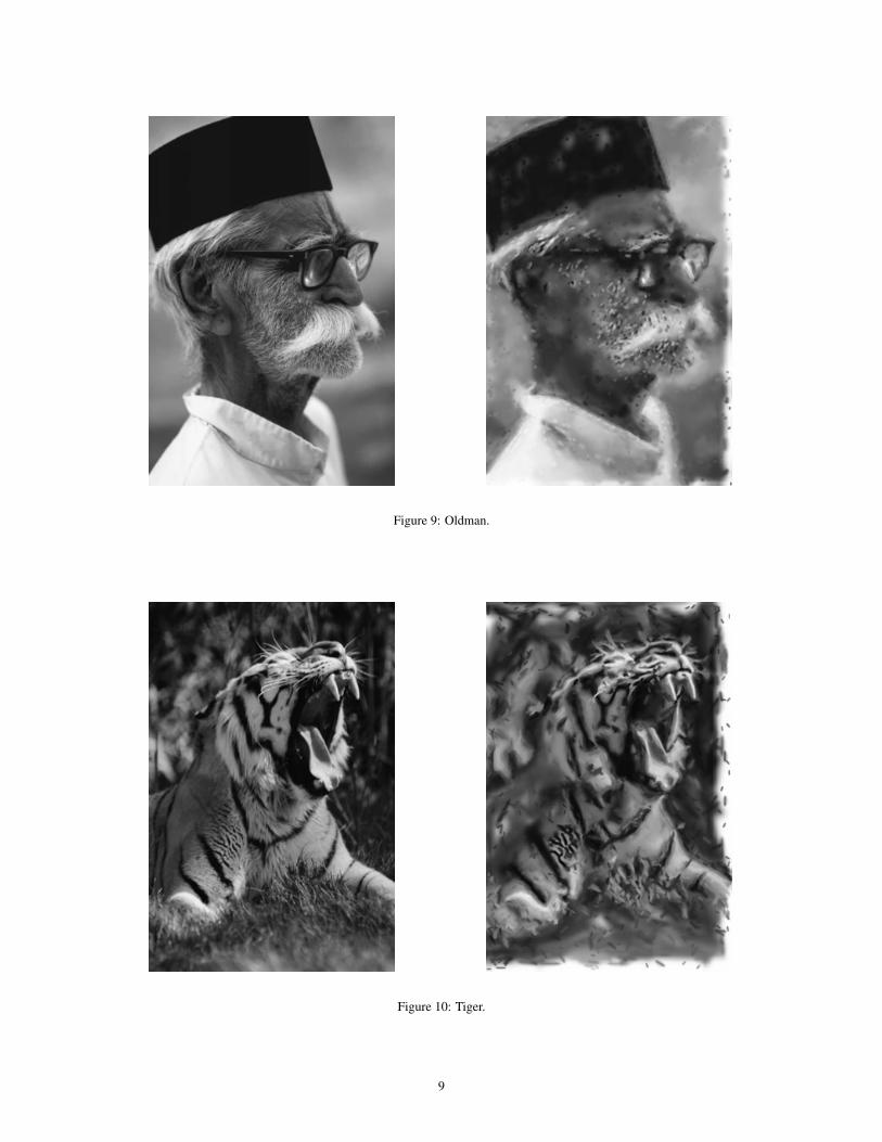
Figure 9: Oldman.
Figure 10: Tiger.
9